THALES ELECTRON DEVICES - CAPP Main · THALES ELECTRON DEVICES For now three months , THOMSON-CSF...
24
THALES ELECTRON DEVICES THALES ELECTRON DEVICES
Transcript of THALES ELECTRON DEVICES - CAPP Main · THALES ELECTRON DEVICES For now three months , THOMSON-CSF...
T H A L E S E L E C T R O N D E V I C E S
T H A L E S E L E C T R O N DEV ICES
T H A L E S E L E C T R O N D E V I C E S
For now three months ,THOMSON-CSF
changed its name for THALES
THOMSON TUBES ELECTRONIQUESis now
THALES ELECTRON DEVICES
T H A L E S E L E C T R O N D E V I C E S
RF High Power CW Sources for the VLLC Project
Philippe J. GUIDEEMarketing for Scientific Applications
THALES ELECTRON DEVICES ( TED )
-----------------------with the contribution of
the R&D teams of the Microwave and Gridded tubes
TED Strategic Business Units--------------------------------
IIT - Chicago - March 9 - 11 , 2001
T H A L E S E L E C T R O N D E V I C E S
RF Sources for VLLC - Design criteria (1)
• Large RF power facilities require a precise analysis of the
Life Cycle Cost ( LCC )
for giving the most advantageous balance of technical performances
vs overall price .
• Fundamental RF criteria for design at optimized cost are :
- the unit RF power
- the efficiency
- the reliability
- the possibility to feed several RF sources with the same HVPS
- the VSWR withstanding .
T H A L E S E L E C T R O N D E V I C E S
RF Sources for VLLC - Design criteria (2)
• Other important criteria are :- the RF frequency : standard or specific
- the beam parameters ( i.e. cathode voltage & current ) - the gain of the end power stage
- the flexibility of operation
• RF power transmission to the accelerator ( length & size of the
lines , transmission losses ,circulator , RF window , RF coupler
limitations and so on ) is another major design factor .
T H A L E S E L E C T R O N D E V I C E S
RF Sources for VLLC - Possible candidates
• Klystron
• Multi-Beam Klystron ( MBK )
• Inductive Output Tube ( IOT )
T H A L E S E L E C T R O N D E V I C E S
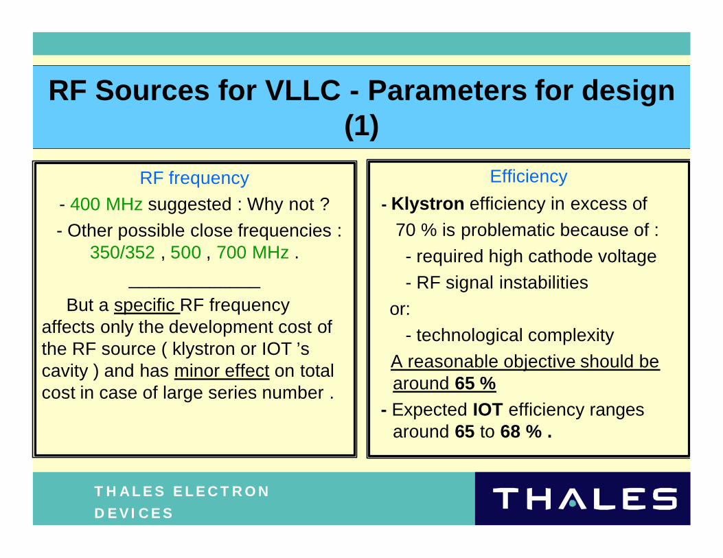
RF Sources for VLLC - Parameters for design (1)
RF frequency
- 400 MHz suggested : Why not ?
- Other possible close frequencies : 350/352 , 500 , 700 MHz .
_____________
But a specific RF frequencyaffects only the development cost of the RF source ( klystron or IOT ’s cavity ) and has minor effect on total cost in case of large series number .
Efficiency
- Klystron efficiency in excess of
70 % is problematic because of :
- required high cathode voltage
- RF signal instabilities
or:
- technological complexity
A reasonable objective should be around 65 %
- Expected IOT efficiency rangesaround 65 to 68 % .
T H A L E S E L E C T R O N D E V I C E S
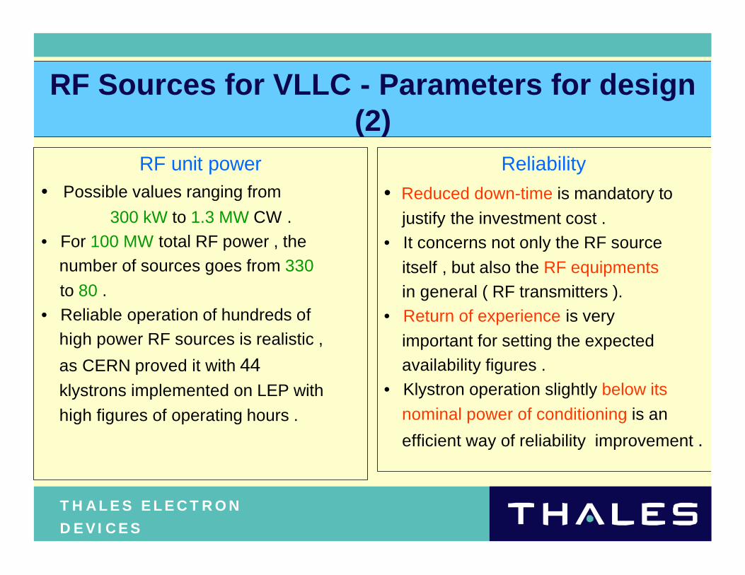
RF Sources for VLLC - Parameters for design (2)
RF unit power• Possible values ranging from
300 kW to 1.3 MW CW .
• For 100 MW total RF power , the
number of sources goes from 330
to 80 .
• Reliable operation of hundreds of
high power RF sources is realistic ,
as CERN proved it with 44 klystrons implemented on LEP with
high figures of operating hours .
Reliability
• Reduced down-time is mandatory to
justify the investment cost .
• It concerns not only the RF source
itself , but also the RF equipments
in general ( RF transmitters ).
• Return of experience is very
important for setting the expected
availability figures .
• Klystron operation slightly below its
nominal power of conditioning is an
efficient way of reliability improvement .
T H A L E S E L E C T R O N D E V I C E S
RF Sources for VLLC - Klystron option (1)
à Well known device with proven feasility
à Coverage of the whole frequency-power range
à Its size explains its high reliability
Really a conservative option for the peace of mind of a project leader .
T H A L E S E L E C T R O N D E V I C E S
RF Sources for VLLC - Klystron option (2)
Reliability operational data - TH 2089 at CERN
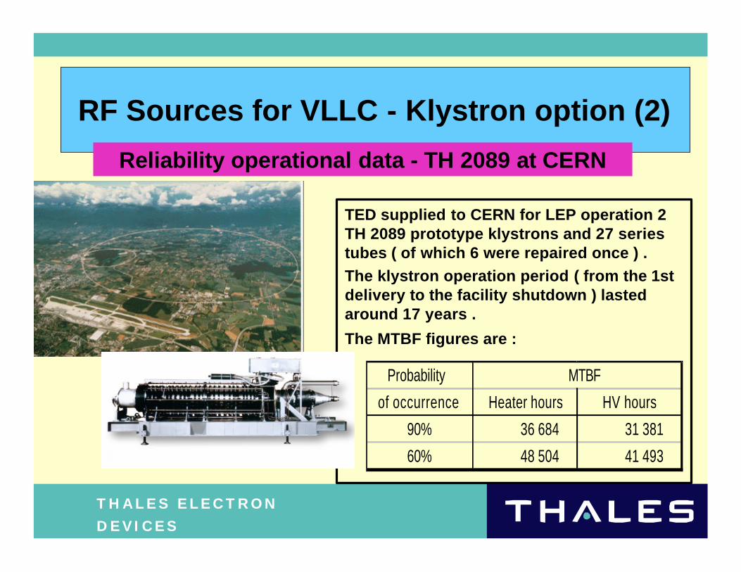
TED supplied to CERN for LEP operation 2 TH 2089 prototype klystrons and 27 series tubes ( of which 6 were repaired once ) .
The klystron operation period ( from the 1st delivery to the facility shutdown ) lasted around 17 years .
The MTBF figures are :
Probability MTBF
of occurrence Heater hours HV hours
90% 36 684 31 381
60% 48 504 41 493
T H A L E S E L E C T R O N D E V I C E S
RF Sources for VLLC - Klystron option (3)
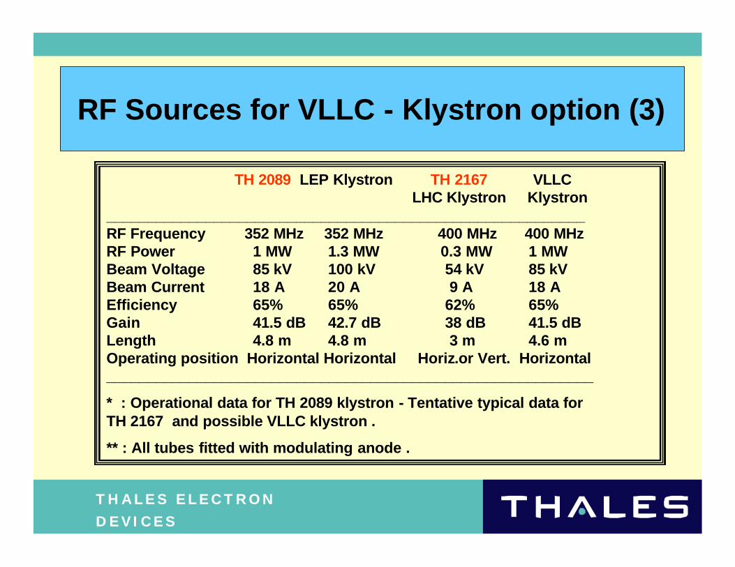
TH 2089 LEP Klystron TH 2167 VLLCLHC Klystron Klystron
__________________________________________________________RF Frequency 352 MHz 352 MHz 400 MHz 400 MHzRF Power 1 MW 1.3 MW 0.3 MW 1 MWBeam Voltage 85 kV 100 kV 54 kV 85 kVBeam Current 18 A 20 A 9 A 18 AEfficiency 65% 65% 62% 65%Gain 41.5 dB 42.7 dB 38 dB 41.5 dB Length 4.8 m 4.8 m 3 m 4.6 mOperating position Horizontal Horizontal Horiz.or Vert. Horizontal___________________________________________________________
* : Operational data for TH 2089 klystron - Tentative typical data for TH 2167 and possible VLLC klystron .
** : All tubes fitted with modulating anode .
T H A L E S E L E C T R O N D E V I C E S
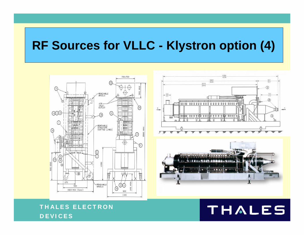
RF Sources for VLLC - Klystron option (4)
T H A L E S E L E C T R O N D E V I C E S
RF Sources for VLLC - MBK option (1)
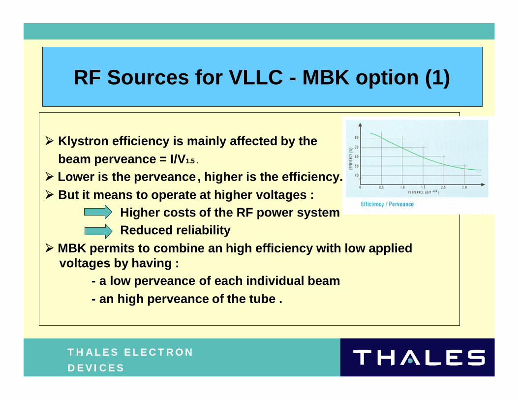
ØØ Klystron efficiency is mainly affected by the beam perveance = I/V1.5 .
ØØ Lower is the perveance, higher is the efficiency.ØØ But it means to operate at higher voltages :
Higher costs of the RF power systemReduced reliability
ØØ MBK permits to combine an high efficiency with low applied voltages by having :
- a low perveance of each individual beam - an high perveance of the tube .
T H A L E S E L E C T R O N D E V I C E S
RF Sources for VLLC - MBK option (2)
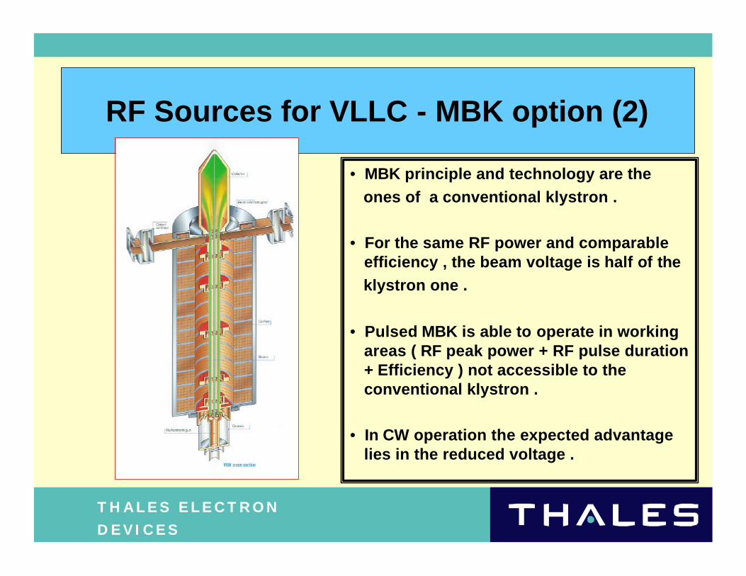
• MBK principle and technology are the
ones of a conventional klystron .
• For the same RF power and comparable efficiency , the beam voltage is half of the
klystron one .
• Pulsed MBK is able to operate in working areas ( RF peak power + RF pulse duration + Efficiency ) not accessible to the conventional klystron .
• In CW operation the expected advantage lies in the reduced voltage .
T H A L E S E L E C T R O N D E V I C E S
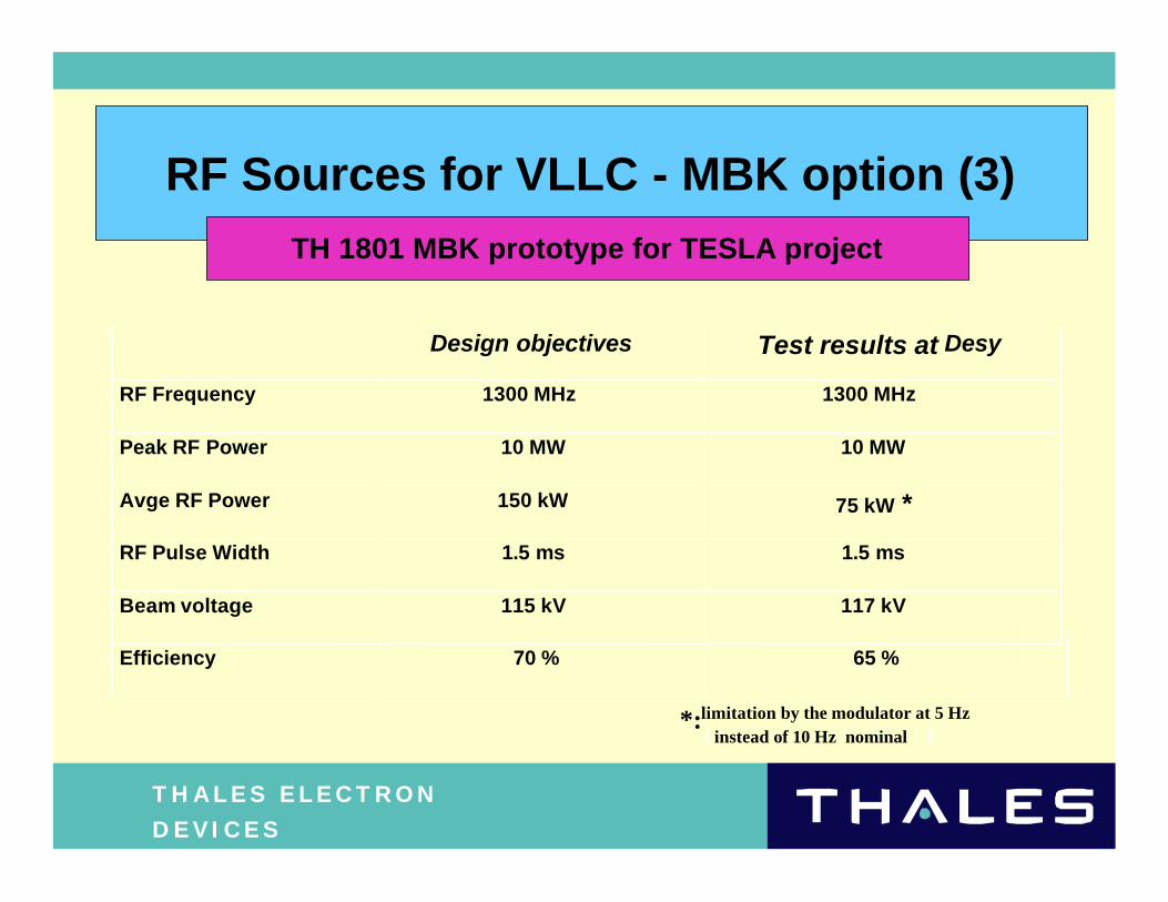
RF Sources for VLLC - MBK option (3)TH 1801 MBK prototype for TESLA project
Design objectives Test results at Desy
RF Frequency 1300 MHz 1300 MHz
Peak RF Power 10 MW 10 MW
Avge RF Power 150 kW 75 kW *
RF Pulse Width 1.5 ms 1.5 ms
Beam voltage 115 kV 117 kV
Efficiency 70 % 65 %
*:limitation by the modulator at 5 Hz( instead of 10 Hz nominal )
T H A L E S E L E C T R O N D E V I C E S
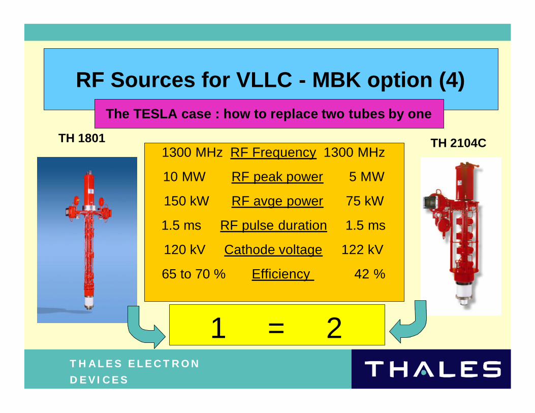
RF Sources for VLLC - MBK option (4)The TESLA case : how to replace two tubes by one
TH 1801 TH 2104C1300 MHz RF Frequency 1300 MHz
10 MW RF peak power 5 MW
150 kW RF avge power 75 kW
1.5 ms RF pulse duration 1.5 ms
120 kV Cathode voltage 122 kV
65 to 70 % Efficiency 42 %
1 = 2
T H A L E S E L E C T R O N D E V I C E S
RF Sources for VLLC - MBK option (5)
Conclusions
ÄThe feasibility of high peak power MBKs is now proven with the tube developed for TESLA project .
ÄThe 1.3 GHz RF frequency of TESLA was a real challenge for design .
Ä In this respect , the 350 to 700 MHz frequency range is much more accessible to MBK .
ÄThe MBK requires additional development work for a completetechnical benchmarking versus conventional klystron .
ÄThe ideal case is the possibility to replace two tubes by one : all accelerator designs don ’t permit it .
T H A L E S E L E C T R O N D E V I C E S
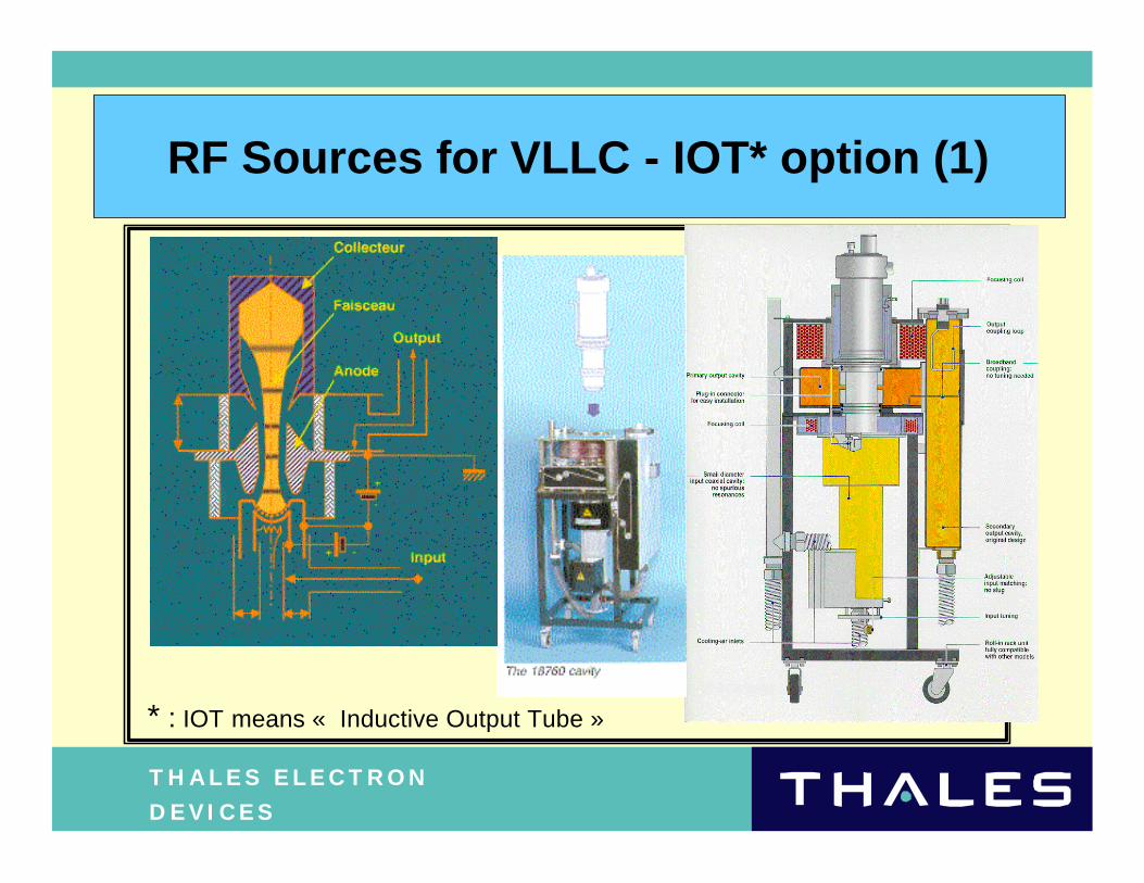
RF Sources for VLLC - IOT* option (1)
* : IOT means « Inductive Output Tube »
T H A L E S E L E C T R O N D E V I C E S
RF Sources for VLLC - IOT option (2)
• Return of experience from the TV application :
- in CW operation
- at lower power level ( tens of kW ) .
• 3OO-kW IOT seems feasible but requires a development effort to become an operational solution
• Some critical issues have to be addressed
• IOT offers attractive features ( high efficiency , compact size ) but its reliability at high power , i.e. hundreds of kW , is not proven .
T H A L E S E L E C T R O N D E V I C E S
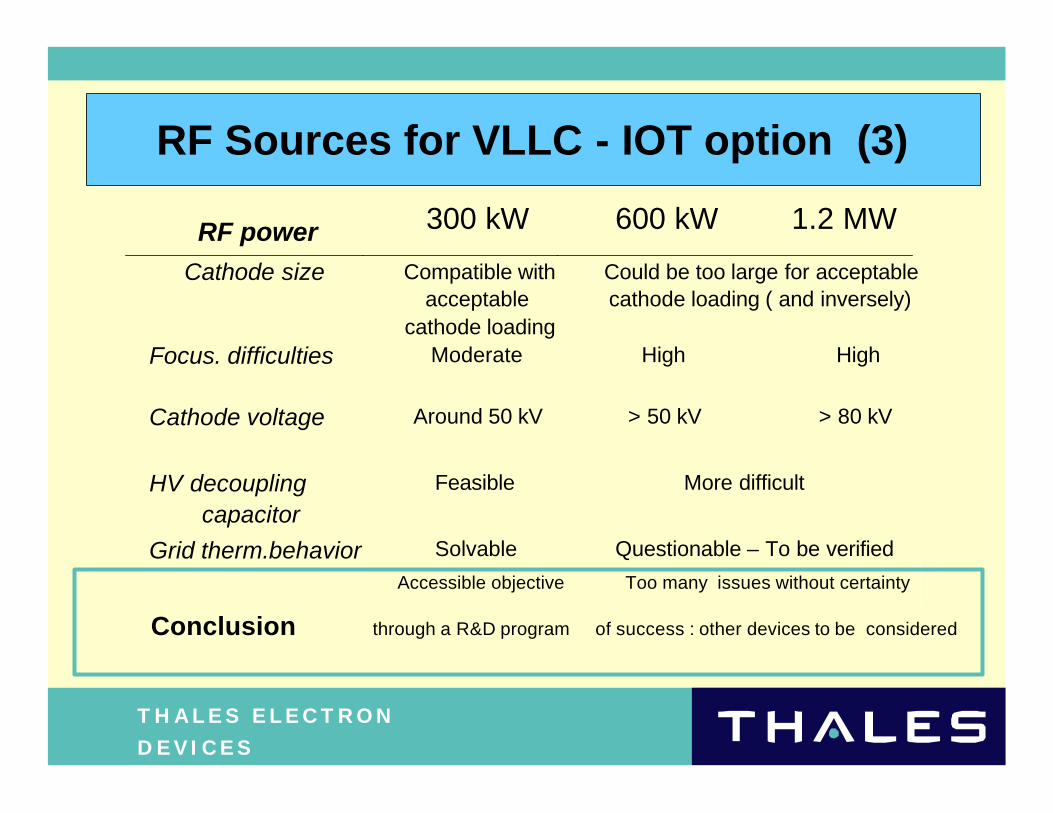
RF Sources for VLLC - IOT option (3)
300 kW 600 kW 1.2 MW
Cathode size Compatible withacceptable
cathode loading
Could be too large for acceptablecathode loading ( and inversely)
Focus. difficulties Moderate High High
Cathode voltage Around 50 kV > 50 kV > 80 kV
HV decouplingcapacitor
Feasible More difficult
Grid therm.behavior Solvable Questionable – To be verified
Accessible objective Too many issues without certainty
Conclusion through a R&D program of success : other devices to be considered
RF power
T H A L E S E L E C T R O N D E V I C E S
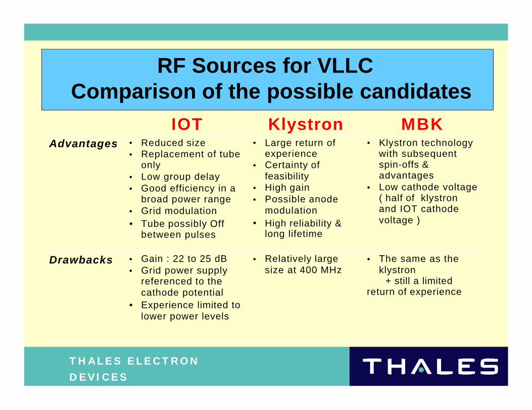
RF Sources for VLLCComparison of the possible candidates
IOT Klystron MBKAdvantages • Reduced size
• Replacement of tubeonly
• Low group delay• Good efficiency in a
broad power range• Grid modulation• Tube possibly Off
between pulses
• Large return ofexperience
• Certainty offeasibility
• High gain• Possible anode
modulation• High reliability &
long lifetime
• Klystron technologywith subsequentspin-offs &advantages
• Low cathode voltage( half of klystronand IOT cathodevoltage )
Drawbacks • Gain : 22 to 25 dB• Grid power supply
referenced to thecathode potential
• Experience limited tolower power levels
• Relatively largesize at 400 MHz
• The same as theklystron
+ still a limitedreturn of experience
T H A L E S E L E C T R O N D E V I C E S
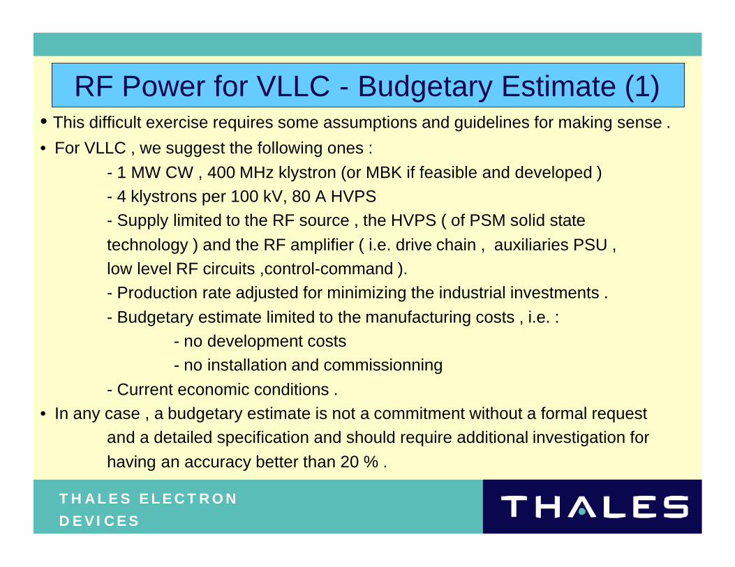
RF Power for VLLC - Budgetary Estimate (1)• This difficult exercise requires some assumptions and guidelines for making sense .
• For VLLC , we suggest the following ones :
- 1 MW CW , 400 MHz klystron (or MBK if feasible and developed )
- 4 klystrons per 100 kV, 80 A HVPS
- Supply limited to the RF source , the HVPS ( of PSM solid state
technology ) and the RF amplifier ( i.e. drive chain , auxiliaries PSU ,
low level RF circuits ,control-command ).
- Production rate adjusted for minimizing the industrial investments .
- Budgetary estimate limited to the manufacturing costs , i.e. :
- no development costs
- no installation and commissionning
- Current economic conditions .
• In any case , a budgetary estimate is not a commitment without a formal request
and a detailed specification and should require additional investigation for
having an accuracy better than 20 % .
T H A L E S E L E C T R O N D E V I C E S
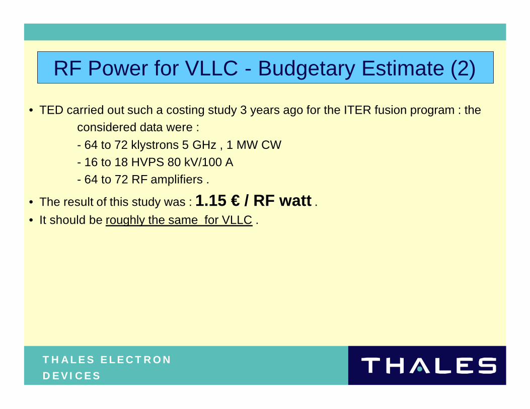
RF Power for VLLC - Budgetary Estimate (2)
• TED carried out such a costing study 3 years ago for the ITER fusion program : the
considered data were :
- 64 to 72 klystrons 5 GHz , 1 MW CW
- 16 to 18 HVPS 80 kV/100 A
- 64 to 72 RF amplifiers .
• The result of this study was : 1.15 € / RF watt .
• It should be roughly the same for VLLC .
T H A L E S E L E C T R O N D E V I C E S
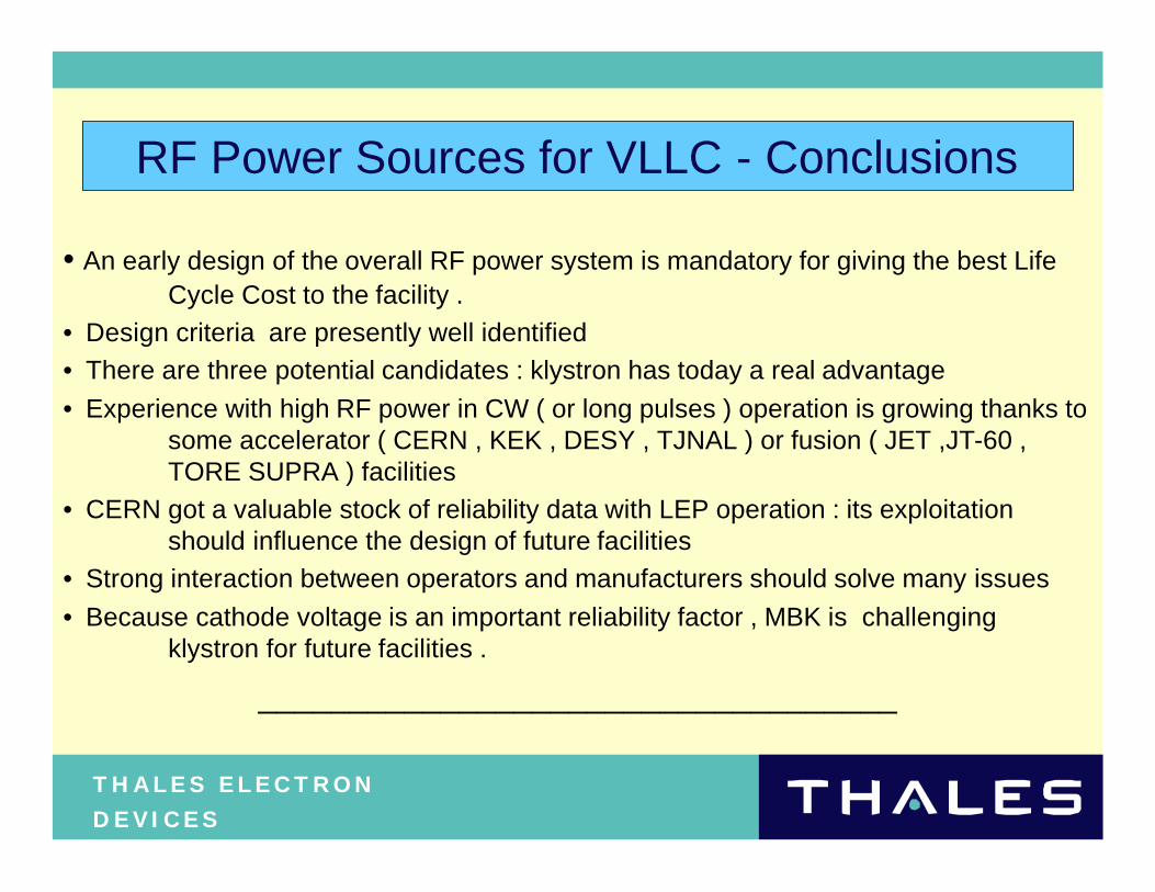
RF Power Sources for VLLC - Conclusions
• An early design of the overall RF power system is mandatory for giving the best Life Cycle Cost to the facility .
• Design criteria are presently well identified
• There are three potential candidates : klystron has today a real advantage
• Experience with high RF power in CW ( or long pulses ) operation is growing thanks to some accelerator ( CERN , KEK , DESY , TJNAL ) or fusion ( JET ,JT-60 , TORE SUPRA ) facilities
• CERN got a valuable stock of reliability data with LEP operation : its exploitation should influence the design of future facilities
• Strong interaction between operators and manufacturers should solve many issues
• Because cathode voltage is an important reliability factor , MBK is challenging klystron for future facilities .
___________________________________