
Test Planning Guide for High Speed Wind Tunnels · 27.04.2005 · Test Planning Guide for High...
129
Wind Tunnel Operations Division Test Planning Guide for High Speed Wind Tunnels A027-9391-XB2 Revision 5 April 27, 2005 This is a controlled document. Printed copies are for reference only. The official version of this document is at http://ao.arc.nasa.gov. Prepared by the Technical Publications Group for The Wind Tunnel Operations Division, Ames Research Center, Moffett Field, California
Transcript of Test Planning Guide for High Speed Wind Tunnels · 27.04.2005 · Test Planning Guide for High...

Wind Tunnel Operations Division
Test Planning Guidefor
High Speed Wind Tunnels
A027-9391-XB2
Revision 5April 27, 2005
This is a controlled document. Printed copies are for reference only.The official version of this document is at http://ao.arc.nasa.gov.
Prepared by the Technical Publications Group forThe Wind Tunnel Operations Division,
Ames Research Center,Moffett Field, California

Test Planning Guide for High Speed Wind Tunnels
A027-9391-XB2 i Revision 5
Record of Changes
Change Date Entered Description Initiated by
Change A 4/98 CR 1408 A. Crozier
Revision 2 4/99 CR 1565 A. Crozier
Revision 3 11/99 CR 1633, Deleted 8x7ft and 14ft. J. Campbell
Revision 4 4/00 CR 1688, Deleted PSCL. J. Campbell
Revision 5 1/14/03 CR 2879, Changed FOW and FOF to FOO F. Kmak
Revision 5a
9/8/03 CR 2902, Changed 11 Foot and 9x7Operating Characteristics. Updated Balance inventory. Note: New revision numbers are noted on the changed pages.
F. Kmak
Revision 5b
4/27/05 CR 3039, Chapter 4.0 Environment, Health and Safety was extensively revised and replaced in its entirety. New revision numbers are noted on the changed pages.
S. Nikodym

Test Planning Guide for High Speed Wind Tunnels
A027-9391-XB2 ii Revision 5
Table of Contents
Paragraph Paragraph PageNumber Title Number
1.0 Introduction........................................................................................................1-1Purpose of This Test Planning Guide..................................................................1-1Wind Tunnel Availability ......................................................................................1-1List of Facilities....................................................................................................1-1Inquiries...............................................................................................................1-1Document Control................................................................................................1-2
2.0 Pretest Requirements........................................................................................2-1Initial Requests....................................................................................................2-1Requesting Tunnel Time .....................................................................................2-1
2.1 Test Obectives Meeting.......................................................................................2-1Purpose ...............................................................................................................2-1Scheduling the Meeting.......................................................................................2-1Typical Meeting Agenda......................................................................................2-2Test Acceptance..................................................................................................2-2
2.2 Initial Test Planning Meeting and Test Requirements Document (TRD).............2-2Purpose ...............................................................................................................2-2Test Requirements Document.............................................................................2-2Description of Test Objectives.............................................................................2-3Model Hardware ..................................................................................................2-3Instrumentation Requirements ............................................................................2-3Data Processing Requirements...........................................................................2-3Security Requirements (if applicable)..................................................................2-3
2.3 Customer Agreement...........................................................................................2-32.4 Model and Equipment Delivery............................................................................2-5
Timely Arrival.......................................................................................................2-5Preassembly Requirements ................................................................................2-5Shipping Information............................................................................................2-5Identification or Unsuitability of Customer Equipment.........................................2-5
3.0 General Information...........................................................................................3-1Primary Point of Contact......................................................................................3-1Communications..................................................................................................3-1Cafeteria Hours ...................................................................................................3-1Office Space........................................................................................................3-1Visitor Control......................................................................................................3-1
3.1 Security................................................................................................................3-1Advance Notification Requirements ....................................................................3-1Secret or Confidential Clearances.......................................................................3-2Badges ................................................................................................................3-2Signing In.............................................................................................................3-2

Test Planning Guide for High Speed Wind Tunnels
A027-9391-XB2 iii Revision 5
Table of Contents
Paragraph Paragraph PageNumber Title Number3.2 Planning...............................................................................................................3-2
Normal Operating Hours......................................................................................3-2Off-Shift Coverage...............................................................................................3-2Test Safety Meeting and Test Debriefing ............................................................3-2Charges for Test Time.........................................................................................3-3Computation of Test Time ...................................................................................3-3
3.3 Support ................................................................................................................3-4Requests for Assistance......................................................................................3-4Model Buildup......................................................................................................3-4Customer Responsibility......................................................................................3-4Government Equipment.......................................................................................3-4Shop Services .....................................................................................................3-5Photographic Services.........................................................................................3-5Balance Availability and Calibration ....................................................................3-5Time Estimates....................................................................................................3-6
4.0 Environment, Health and Safety.......................................................................4-1Description...........................................................................................................4-1
4.1 Emergency Information........................................................................................4-1Emergencies........................................................................................................4-1Evacuation...........................................................................................................4-1Fire ......................................................................................................................4-1Earthquake ..........................................................................................................4-1Injuries and Treatment.........................................................................................4-2Personal Illness ...................................................................................................4-2
4.2 Wind Tunnel Hazards ..........................................................................................4-2General................................................................................................................4-2Aerial Lifts............................................................................................................4-2Confined Spaces .................................................................................................4-2Cranes/ Lifting Devices........................................................................................4-2Electrical..............................................................................................................4-2Ergonomics..........................................................................................................4-2Fall Protection......................................................................................................4-3High Pressure......................................................................................................4-3Lead.....................................................................................................................4-3Lock-out/Tag-out .................................................................................................4-3Mechanical ..........................................................................................................4-3Noise ...................................................................................................................4-3Sharp edges ........................................................................................................4-3Trips, Bumps, and Falls.......................................................................................4-4Wind Tunnel Entry...............................................................................................4-4

Test Planning Guide for High Speed Wind Tunnels
A027-9391-XB2 iv Revision 5
Table of Contents
Paragraph Paragraph PageNumber Title Number
Working Alone .....................................................................................................4-44.3 Hazardous Materials............................................................................................4-5
Definition..............................................................................................................4-5Berylium Alloys....................................................................................................4-5Material Safety Data Sheets................................................................................4-5Hazardous Material Approval Process ................................................................4-5Labels..................................................................................................................4-5Operations Involving Hazardous Materials..........................................................4-5Customer-Generated Hazardous Waste .............................................................4-6Spills....................................................................................................................4-6
4.4 Protective Equipment...........................................................................................4-6General................................................................................................................4-6
4.5 Personnel Training................................................................................................4-6General................................................................................................................4-6
4.6 Laser Safety..........................................................................................................4-7Safety Standards.................................................................................................4-7Approval Authority ...............................................................................................4-7Authorized Laser Customers...............................................................................4-7Safety Eye Wear..................................................................................................4-7Required Ophthalmologic Exam..........................................................................4-7
4.7 Other Safety Guidelines........................................................................................4-7Bloodborne Pathogens........................................................................................4-7Equipment ...........................................................................................................4-7Housekeeping......................................................................................................4-7Permits ................................................................................................................4-8Postings...............................................................................................................4-8Storm Drains........................................................................................................4-8Vehicles...............................................................................................................4-8
4.8 References ...........................................................................................................4-85.0 Risk Assessment and Safety Review Requirements...........................................5-1
Introduction..........................................................................................................5-15.1 Risk Assessment .................................................................................................5-1
Overview..............................................................................................................5-1Hazard severity....................................................................................................5-2Hazard probability................................................................................................5-2Risk Assessment Approval..................................................................................5-3Hazard Controls...................................................................................................5-3
5.2 Model Safety Requirements ................................................................................5-4Stress Report.......................................................................................................5-4Stress Report Changes .......................................................................................5-4

Test Planning Guide for High Speed Wind Tunnels
A027-9391-XB2 v Revision 5
Table of Contents
Paragraph Paragraph PageNumber Title Number
Stress Report Contents Overview .......................................................................5-4Other Requirements ............................................................................................5-5Formal Design Review ........................................................................................5-5
5.3 Design Criteria.....................................................................................................5-5Overview..............................................................................................................5-5
Stress Analysis........................................................................................................5-5Stress Analysis Overview....................................................................................5-5Stresses or Loads................................................................................................5-6Forces and Moments...........................................................................................5-6General Equations...............................................................................................5-6Air-Loaded Surfaces............................................................................................5-6Section Properties ...............................................................................................5-6Air Loads .............................................................................................................5-7Static Test Instead of Stress Analysis .................................................................5-7Gauged Components with Stress Analysis .........................................................5-7Reduced Requirements.......................................................................................5-7Previously Tested Components...........................................................................5-7
Material Selection....................................................................................................5-8Materials Standards.............................................................................................5-8Mechanical Properties Corrections......................................................................5-8
Allowable Strength ..................................................................................................5-8Safety Factors .....................................................................................................5-8Shear Stresses....................................................................................................5-8Thermal Stresses ................................................................................................5-8Material Properties ..............................................................................................5-8Buckling Stress....................................................................................................5-8Oscillating Stresses.............................................................................................5-9Impact Strength ...................................................................................................5-9
Structural Joints.......................................................................................................5-9Fastener Quality Standards.................................................................................5-9Fastener Assembly..............................................................................................5-9Structural Joint Drawings.....................................................................................5-9Mil Spec Standards for Joints............................................................................5-10Welded Joints....................................................................................................5-10Shear Loads (bolted joints)................................................................................5-10Bolt Preload.......................................................................................................5-10Thread Engagements........................................................................................5-10Countersinks, Counterbores and Spot Faces....................................................5-10Small Screws.....................................................................................................5-11Screw Joints ......................................................................................................5-11

Test Planning Guide for High Speed Wind Tunnels
A027-9391-XB2 vi Revision 5
Table of Contents
Paragraph Paragraph PageNumber Title Number
Bolted Joints......................................................................................................5-11Fastener Locking...............................................................................................5-11
Pressure Systems .................................................................................................5-11High-pressure Air Availability.............................................................................5-11Pressure-Relief Devices....................................................................................5-11Pressure System Codes....................................................................................5-12Pressure System Components..........................................................................5-12Pressure Vessel ................................................................................................5-13Pressure Piping .................................................................................................5-13
Electrical Equipment..............................................................................................5-14General..............................................................................................................5-14Material Criteria .................................................................................................5-14Fuses and Shielded Wires.................................................................................5-14User-Furnished Electrical Materials...................................................................5-14
Model Support Systems ........................................................................................5-15Specification ......................................................................................................5-15Aerodynamic Interference .................................................................................5-15Model Support Hardware...................................................................................5-15
5.4 Model Fabrication Requirements.......................................................................5-16General..............................................................................................................5-16Model Assembly ................................................................................................5-16
5.5 Model Acceptance Criteria.................................................................................5-17Model Acceptance.............................................................................................5-17Inspections ........................................................................................................5-17Structural Reports..............................................................................................5-17Waivers..............................................................................................................5-17
6.0 General Test Support Systems ........................................................................6-16.1 High-Pressure Air ................................................................................................6-1
Air Pumping and Storage Capacities...................................................................6-1Air Heaters...........................................................................................................6-1Low Air Heater Flows ..........................................................................................6-1Facilities Available for Heater Setup....................................................................6-2
6.2 Hydraulic Systems...............................................................................................6-2Portable Systems ................................................................................................6-2Unitary Model Prep Rooms .................................................................................6-2
6.3 Separation Support System.................................................................................6-2Angular Displacement .........................................................................................6-2Available Facilities...............................................................................................6-3Maximum Displacement Capability .....................................................................6-3

Test Planning Guide for High Speed Wind Tunnels
A027-9391-XB2 vii Revision 5
Table of Contents
Paragraph Paragraph PageNumber Title Number
Load Limits ..........................................................................................................6-36.4 Roll Adapters .......................................................................................................6-3
Available Facilities...............................................................................................6-3Capacities............................................................................................................6-4
7.0 Description of Test Facilities............................................................................7-1Facilities...............................................................................................................7-1Unitary Plan Wind Tunnels..................................................................................7-1Other Tunnels......................................................................................................7-1
7.1 11ft Transonic Wind Tunnel.................................................................................7-1Description...........................................................................................................7-1Operating Characteristics....................................................................................7-1Test Section Dimensions.....................................................................................7-3Model Installation Diagram..................................................................................7-4Forward and Aft Limits.........................................................................................7-4Forces and Moments...........................................................................................7-5Load Compensation ............................................................................................7-5Turntable Model Support.....................................................................................7-5Semispan Testing................................................................................................7-6Installation and Personnel Access.......................................................................7-6Flow Visualization................................................................................................7-6High-Pressure Air ................................................................................................7-6
7.2 9x7ft Supersonic Wind Tunnel.............................................................................7-6Description...........................................................................................................7-6Operating Characteristics....................................................................................7-6Test Section Dimensions.....................................................................................7-8Model Installation Diagram...................................................................................79Model Support System ........................................................................................7-9Forces and Moments.........................................................................................7-10Flow Visualization..............................................................................................7-10High-Pressure Air ..............................................................................................7-10Reflected Shock Waves ....................................................................................7-10Starting Loads ...................................................................................................7-10
7.3 12ft Pressure Wind Tunnel ................................................................................7-12Facility Description ............................................................................................7-12Operating Characteristics..................................................................................7-12Airflow................................................................................................................7-13Settling Chamber...............................................................................................7-14Test Section.......................................................................................................7-14Test Section Isolation System ...........................................................................7-14

Test Planning Guide for High Speed Wind Tunnels
A027-9391-XB2 viii Revision 5
Table of Contents
Paragraph Paragraph PageNumber Title Number
Model Support Systems ....................................................................................7-15Control Room Features .....................................................................................7-16Tunnel Operating Modes...................................................................................7-17Features of Model Preparation Rooms..............................................................7-17
Appendix A Checking Taper Fits...........................................................................A-1Taper Fits ........................................................................................................... A-1 Taper Fit Procedures......................................................................................... A-1
Appendix B List of Sting Hardware in Ames Inventory.......................................B-1Table Legend...................................................................................................... B-1Examples............................................................................................................ B-1Sting Hardware Table......................................................................................... B-3
Appendix C Summary of Customer Actions and Deliverables...........................C-1C.1 General Checklist...............................................................................................C-1C.2 Test Request Form.............................................................................................C-2C.3 Initial Test Planning Meeting Guide ...................................................................C-6
C.4 Test Requirements Document Outline......................................................C-9
Appendix D 12ft PWT, Instrumentation, Data Acquisition, and Data Reduction ..........................................................................D-1
Introduction.........................................................................................................D-1Sensors ..............................................................................................................D-1Instrumentation Wiring, pneumatics, And Fiber Optics ......................................D-1Control Room .....................................................................................................D-2Model Preparation Sites .....................................................................................D-2
D.1 Sensors Available at Ames ................................................................................D-3Force Balances...................................................................................................D-3Pressure Measurements ....................................................................................D-5Tilt Sensors.........................................................................................................D-6
D.2 Institutional (Instrumentation) Cables, Pneumatics, and Fiber Optics ...............D-7Description..........................................................................................................D-7
D.3 Data Acquisition ...............................................................................................D-12Functional Subsystems ....................................................................................D-12Force Balances.................................................................................................D-13General Purpose Digital Input ..........................................................................D-14Temperatures ...................................................................................................D-14General Purpose Analog Inputs .......................................................................D-15Tunnel Conditions and Model Support Positions..............................................D-15Wall Interference Correction System (WICS)...................................................D-16
Test Planning Guide for High Speed Wind Tunnels
A027-9391-XB2 ix Revision 5
Table of Contents
Paragraph Paragraph PageNumber Title Number
D.4 Image Plane Pressure Instrumentation............................................................D-16D.5 Subsystem Management Processor ................................................................D-17
Description........................................................................................................D-17D.6 Data Reduction ................................................................................................D-18
General.............................................................................................................D-18D.7 Available Processes.........................................................................................D-19
Real Time Displays...........................................................................................D-19Graphics ...........................................................................................................D-19Standard Computations....................................................................................D-20Test Specific Computations..............................................................................D-20Output...............................................................................................................D-20
D.8 Deliverables .....................................................................................................D-21Data Transmittal ...............................................................................................D-21Security.............................................................................................................D-21

Test Planning Guide for High Speed Wind Tunnels
A027-9391-XB2 x Revision 5
List of Figures
Figure Figure PageNumber Title NumberFigure 7-1: 11ft Transonic Wind Tunnel Operating Characteristics...................... 7-2Figure 7-2: 11ft Transonic Wind Tunnel Test Section Dimensions....................... 7-3Figure 7-3: 11ft Transonic Wind Tunnel Sting Installation .................................... 7-4Figure 7-4: 9x7ft Supersonic Wind Tunnel Performance Characteristics ............. 7-7Figure 7-5: 9x7ft Supersonic Wind Tunnel Test Section Dimensions................... 7-8Figure 7-6: 9x7ft Supersonic Wind Tunnel Modcel Installation............................. 7-9Figure 7-7: 9x7ft Supersonic Wind Tunnel Load Locations ................................ 7-11Figure 7-8: 9x7ft Supersonic Wind Tunnel Starting Loads ................................. 7-11Figure 7-9: 12ft Pressure Wind Tunnel General Layout ..................................... 7-12Figure 7-10: 12ft Pressure Wind Tunnel Operating Characteristics ..................... 7-13Figure 7-11: 12ft Pressure Wind Tunnel Control Room Layout............................ 7-17Figure 7-12: N206 First Floor Plan View............................................................... 7-18Figure C-1: Test Request Form (Sheet 1 of 3)...................................................... C-3Figure C-2: Initial Test Planning Meeting Guide (Sheet 1 of 2)............................. C-7Figure C-3: Test Requirements Document Outline (Sheet 1 of 2)....................... C-10Figure D-1: Block Diagram for 12ft PWT Institutional Wiring................................. D-8Figure D-2: Block Diagram for Inputs to the Standardized
Data System (SDS) .......................................................................... D-13
Test Planning Guide for High Speed Wind Tunnels
A027-9391-XB2 xi Revision 5
List of Tables
Table Table PageNumber Title NumberTable 3-1: Advance Notice Requirements........................................................... 3-1Table 3-2: Task Completion Times...................................................................... 3-6Table 5-1: Hazard-Severity Categories ............................................................... 5-2Table 5-2: Hazard-Probability Levels................................................................... 5-2Table 5-3: Risk Assessment Approval levels....................................................... 5-3Table 7-1: 11ft Transonic Wind Tunnel Model Location Limits............................ 7-4Table 7-2: 12ft Pressure Wind Tunnel Turntable Design Characteristics.......... 7-15Table 7-3: 12ft Pressure Wind Tunnel Bipod Design Characteristics................ 7-15Table 7-4: 12ft Pressure Wind Tunnel High Angle Of Attack Design
Characteristics.................................................................................. 7-16Table 7-5: 12ft Pressure Wind Tunnel Rear Sting Design Characteristics........ 7-16Table B-1: Adapters ............................................................................................. B-3Table B-2: Extensions.......................................................................................... B-8Table B-3: Extension/Adapter .............................................................................. B-9Table B-4: Pivot Arms ........................................................................................ B-10Table B-5: Primary Adapters.............................................................................. B-12Table B-6: Primary Adapter/Stings..................................................................... B-13Table B-7: Pylon Fittings.................................................................................... B-14Table B-8: Roll Mechanism/Extensions ............................................................. B-14Table B-9: Stings................................................................................................ B-14Table B-10: Sting/Adapters.................................................................................. B-20Table B-11: Turnbuckle Arm ............................................................................... B-21Table C-1: Customer Supplied Items Checklist.................................................... C-1Table D-1: Six-Component Internal Sting Balances (Task-Able) ......................... D-3Table D-2: Five-component Floor Balance........................................................... D-5Table D-3: Specialty Balances ............................................................................. D-5Table D-4: PSI Pressure Scanner Ranges........................................................... D-6Table D-5: Examples of discrete pressure transducers available ........................ D-6Table D-6: Tilt Sensors Available......................................................................... D-6Table D-7: Turntable Model Support (TRN) ......................................................... D-8Table D-8: Bi-Pod Model Support (BMS) to Control Room.................................. D-9Table D-9: High Angle of Attack Model Support (HAA) to Control Room........... D-10Table D-10: Rear Sting Support, (RSS) ............................................................... D-11Table D-11: Camera Strobe Cables..................................................................... D-12Table D-12: Compatible Temperature Signal Types............................................ D-14Table D-13: Measured Tunnel Parameters......................................................... D-15Table D-14: Model Attitude Data......................................................................... D-16

Test Planning Guide for High Speed Wind Tunnels
A027-9391-XB2 xii Revision 5
List of Acronyms and Abbreviations
Term Definition
AEDNS Ames Engineering Document Number System
AHB Ames Handbook
AMM Ames Management Manual
ANSI American National Standards Institute
ARC Ames Research Center
CAD Computer Aided Design
CAM Computer Aided Manufacturing
CCB Configuration Control Board
CDR Critical Design Review
CM Configuration Management
CMP Configuration Management Plan
CR Change Request
CSI Construction Specification Institute
DSA Document Submittal Authorization
ECO Engineering Change Order
EDC Engineering Documentation Center
FFC Fast Field Change
FMM Facilities Management Manual
IST Integrated System Test
NASA National Aeronautics and Space Administration
NHB NASA Handbook
NMI NASA Management Instruction
ORR Operational Readiness Review
PCA Physical Configuration Audit
PDR Preliminary Design Review
PLC Programmable Logic Controller
PR Peer Review
QA Quality Assurance
SME Subject Matter Expert
SOP Standard Operating Procedures
SDS Standardized Data System

Test Planning Guide for High Speed Wind Tunnels
A027-9391-XB2 xiii Revision 5
TWT Transonic Wind Tunnel
WT Wind Tunnel
Term Definition

Test Planning Guide for High Speed Wind Tunnels
A027-9391-XB2 1-1 Revision 5
1.0 Introduction
Purpose of This Test Planning Guide
The purpose of this guide is to acquaint customers with the requirements for conducting tests in any of the Wind Tunnel Operations Division’s high-speed test facilities at Ames Research Center. It includes available services and capabilities of these facilities and standard practices/procedures to enable customers to achieve their test objectives.
Wind Tunnel Availability
The Wind Tunnel Operations Division high speed wind tunnels are available for Government sponsored and commercial customers. Approval to conduct test programs must be justified on the basis of technical merit, national priority, and the capability of the Ames facilities to meet the test requirements.
Results from all tests are in the public domain and available for general distribution unless the data is proprietary by fee basis or classified by a Government sponsor.
List of Facilities
The Wind Tunnel Operations Division is responsible for the operation of the following high-speed facilities located at the Ames Research Center. • 9x7ft Supersonic Wind Tunnel • 11ft Transonic Wind Tunnel• 12ft Pressure Wind Tunnel
Inquiries
Inquiries regarding the use of these facilities should be directed to:Wind Tunnel Operations DivisionChief Wind Tunnel Operations BranchMail Stop 227-3Ames Research Center Moffett Field, CA 94035Phone: (415) 604- 6698

Test Planning Guide for High Speed Wind Tunnels
A027-9391-XB2 1-2 Revision 5
Document Control
This manual is a controlled document. Any changes must be in accordance with the Wind Tunnel Operations Division Configuration Management Procedures, A027-9391-XB4. Only authorized reproduction or distribution is permitted. All or part of this manual may be printed from the Master Controlled Document located on the Division Web Server. It is the users responsibility to verify that any printout or paper copy of this manual, or part thereof, matches the Master Document on the server. If it does not match, this manual
may not be used.

Test Planning Guide for High Speed Wind Tunnels
A027-9391-XB2 2-1 Revision 5
2.0 Pretest Requirements
Initial Requests
The initial contact to request a wind tunnel test is Chief, Wind Tunnel Opera;tions Branch. The contact should be made during the early stages of test program development (7 to 12 months before tunnel entry date) to discuss projected schedules and general requirements and concerns for tests in Ames Research Center tunnels.
Early notification will allow personnel to review the proposed test and to ensure that test requirements are compatible with the requested test facility and that schedule constraints can be addressed.
Requesting Tunnel Time
The following sequence of events should begin well before the desired test dates (7 months in requested) to be included in the wind tunnel test schedule:• The test sponser/customer contacts the Wind tunnel
Operations Branch Chief.• The customer completes and submits a Test Request form.
See Appendix C for a copy of this form. It is also available electronically in Microsoft® Word. Upon receipt of the Test Request at Ames, a process to accommodate the test begins.
• A Test Objectives Meeting is scheduled to discuss the overall test requirements and the Ames facilities capablilities to meet these requirements.
2.1 Test Objectives Meeting
Purpose
The purpose of the Test Objectives Meeting is for the customer (or test sponsor) to discuss the subject test requirements with Ames/Wind Tunnel Operations Division personnel to determine if the Ames facilities can meet the test objectives. When the required facility is heavily booked, the customer will be required to provide information supporting the urgency of the test.
Scheduling the Meeting
The Test Objectives Meeting will be held as soon as possible after the initial request and preferably 6 months prior to the proposed test start date.

Test Planning Guide for High Speed Wind Tunnels
A027-9391-XB2 2-2 Revision 5
Typical Meeting Agenda
The Test Objectives Meeting covers:• purpose, scope, and criticality of test.• test objectives.• initial instrumentation requirements.• initial controls requirements.• initial data reduction software requirements.• estimated test run matrix.• any special or unusual test requirements.• hardware fabrication requirements.• security requirements.
Test Acceptance
When the test program is accepted:• the customer is notified• a test date is scheduled• a Test Manager is assigned, who functions as the principal
point of contact between the customer and NASA• a Initial Test Planning Meeting is scheduled• resources are committed to support the test• a space act agreement may be required
2.2 Initial Test Planning Meeting and Test Requirements Document (TRD)
Purpose
The purpose of the Initial Test Planning Meeting is to discuss details regarding test requirements. The Test Manager and customer develop detailed plans together, and then management is briefed. The meeting is held nominally 12 weeks prior to the test. See Appendix C for recommended guidelines for the Initial Test Planning Meeting.
Test Requirements Document
The Test Manager must receive a complete TRD from the customer at least one week prior to the Initial Test Planning Meeting. See Appendix C for an outline of the TRD. The document covers the following areas:• Description of Test Objectives• Model Hardware Requirements• Instrumentation Requirements• Data Processing Requirements• Security Requirements (if applicable)

Test Planning Guide for High Speed Wind Tunnels
A027-9391-XB2 2-3 Revision 5
Description of Test Objectives
As part of the TRD, NASA requires a clear statement of the test objectives and techniques to achieve those objectives. Any special techniques or procedures should be explained. The customer must provide a prioritized run schedule compatible with the objectives and allotted test time.
Model Hardware
The TRD must provide drawings of the model, installation, and appropriate hardware to adapt the customer-supplied model to the tunnel or existing Ames equipment. Gauges or jigs can be made available to the customer and they will be sent on request. The customer is to return them within three weeks of receipt. All models tested require a supporting stress analysis. See Section 5.2 for details.
Instrumentation Requirements
The TRD must provide instrumentation requirements and demonstrate how the customer will adapt customer-supplied instrumentation to the wind tunnel data system. Ames will specify the required type of plugs, connectors, etc.
Data Processing Requirements
Data reduction information (data inputs, equations in engineering language, data output format complete with units and scaling for accuracy and resolution) must be submitted to the Test Manager.
Customers must request subsequent changes to these data requirements in writing to the Test Manager for review and approval.
Security Requirements (if applicable)
The TRD must address in specific detail security requirements for model prep room, test section, control room, model access, photography/video, data acquisition, and data processing.
2.3 Customer Agreement
Description
At the conclusion of the Initial Test Planning Meeting or as soon as possible thereafter, the NASA Test Manager will develop a detailed Customer Agreement. This document describes the Division’s and Customer’s deliverables with appropriate milestones and dates identified. The document will address the following items as appropriate:
• Introduction and background of test

Test Planning Guide for High Speed Wind Tunnels
A027-9391-XB2 2-4 Revision 5
• Test milestone dates • Estimate of time required to accomplish test matrix and
objectives• Goals and objectives of test • Customer and division points of contact (Initial Test Planning
Meeting attendees) • Overall requirements (model, model support, facility,
instrumentation, computing) • Test conditions and type(s) of data required• Design reviews /additional requirements meetings• Deliverables/due dates prior to test dates• What the customer will provide in support of the test and when
• equipment, hardware, fabrication • labor resources • analyses • model • any unique requirements for verification, storage, or
maintenance of customer supplied products• What the Division will provide in support of the test and when
• equipment, hardware, fabrication • labor resources • analyses• facility dependent model hardware
The Customer Agreement will be signed by the Division and Customer representatives, distributed to all affected parties, and the original will be archived within the Division.
If during further test preparations significant changes in the Division’s or Customer’s responsibilities, deliverables, or milestones are deemed necessary, these changes will be managed according to the Test Change Control Process as defined in the Wind Tunnel Operations Division Test Process Manual. The Test Manager and Customer representative will agree on the changes, the Test Manager will determine the appropriate level of Division Management involvement, and an addendum to the Customer Agreement will be created and signed by both the test Manager and the Customer representative.
Test Planning Guide for High Speed Wind Tunnels
A027-9391-XB2 2-5 Revision 5
2.4 Model and Equipment Delivery
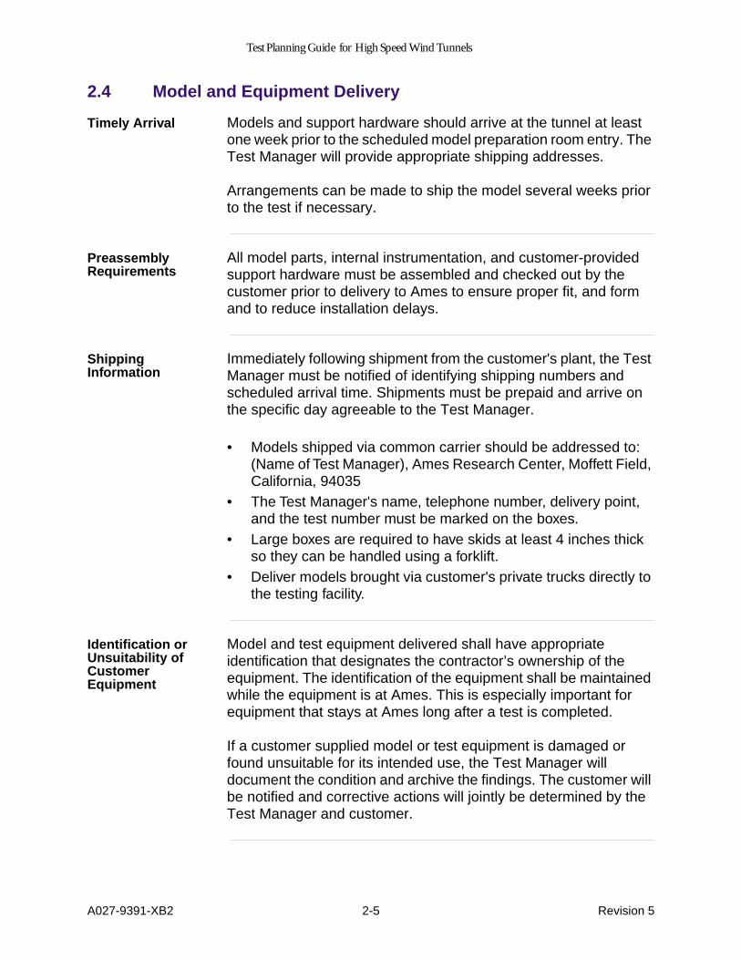
Timely Arrival
Models and support hardware should arrive at the tunnel at least one week prior to the scheduled model preparation room entry. The Test Manager will provide appropriate shipping addresses.
Arrangements can be made to ship the model several weeks prior to the test if necessary.
Preassembly Requirements
All model parts, internal instrumentation, and customer-provided support hardware must be assembled and checked out by the customer prior to delivery to Ames to ensure proper fit, and form and to reduce installation delays.
Shipping Information
Immediately following shipment from the customer's plant, the Test Manager must be notified of identifying shipping numbers and scheduled arrival time. Shipments must be prepaid and arrive on the specific day agreeable to the Test Manager.
• Models shipped via common carrier should be addressed to: (Name of Test Manager), Ames Research Center, Moffett Field, California, 94035
• The Test Manager's name, telephone number, delivery point, and the test number must be marked on the boxes.
• Large boxes are required to have skids at least 4 inches thick so they can be handled using a forklift.
• Deliver models brought via customer's private trucks directly to the testing facility.
Identification or Unsuitability of Customer Equipment
Model and test equipment delivered shall have appropriate identification that designates the contractor’s ownership of the equipment. The identification of the equipment shall be maintained while the equipment is at Ames. This is especially important for equipment that stays at Ames long after a test is completed.
If a customer supplied model or test equipment is damaged or found unsuitable for its intended use, the Test Manager will document the condition and archive the findings. The customer will be notified and corrective actions will jointly be determined by the Test Manager and customer.

Test Planning Guide for High Speed Wind Tunnels
A027-9391-XB2 3-1 Revision 5
3.0 General Information
Primary Point of Contact
The Test Manager functions as the primary point of contact to facilitate requests, requirements, services, and standard procedures for the customer while at Ames Research Center.
Communications
Telephones, FAX machines, and Internet access are available.
Cafeteria Hours
The Ames cafeteria is open from 6:00 a.m. until 2:00 p.m. Monday through Friday.
Office Space
Private office space is not available in the control room but desk and filing space are provided. During preparation and testing, desk space may be available in the model buildup area.
Visitor Control
Visitor Control is located in Building 26, which is located on the right side of the Moffett Boulevard Main Gate. Business hours are from 7:00 a.m. to 4:30 p.m., Monday through Friday. All Ames visitors are required to obtain temporary badges at Visitor Control. Arrivals other than normal business hours must make special arrangements through the Test Manager.
3.1 Security
Advance Notification Requirements
The customer must provide the Test Manager with a list of names and citizenship of all customer personnel who will require entry into Ames for the duration of the test. The times below are the advance notification requirements.
Table 3-1: Advance Notice Requirements
Category of Visitor Advance Notice Required
U. S. Citizen None
Non-U.S. Citizen (nontechnical) 10 days
Non-U.S. Citizen (technical) 5 weeks
Non-U.S. Citizen (employment) (contracts, grants, etc.)
9 weeks; Must have a valid passport and visa in his/her possession
Classified visit 10 days

Test Planning Guide for High Speed Wind Tunnels
A027-9391-XB2 3-2 Revision 5
If these lead times are not adhered to, delays, inconveniences and test stoppage can result.
Secret or Confidential Clearances
If the visit is Secret or Confidential, visitors are required to have their security clearances sent in advance to:
NASA/Ames Research Center Attn: M/S 253-1, Visitor Control Moffett Field, CA 94035-1000(415) 604- 5590
Badges
While at Ames, all customer personnel are required to wear badges as issued by Visitor Control. The Test Manager is responsible for coordinating with the customer how and when to obtain badges and their applicable requirements (i.e. for second and third shifts, etc.).
Signing In
Upon arrival, all customers are requested to sign in with the assigned Test Manager. They are to provide local addresses and telephone numbers so calls and correspondence may be directed to the proper place.
3.2 Planning
Normal Operating Hours
Test facilities are operated on a normal five-day week beginning 11:30pm Sunday until midnight Friday. Consult the Test Manager regarding the specific shift hours because they vary between test facilities.
Off-Shift Coverage
Access to the test facility on shifts other than operating shifts must be coordinated through the Test Manager. Customer personnel are not permitted to work in the facility without facility personnel present.
Test Safety Review and Test Debriefing
A test safety review is held just prior to beginning test operations to review operations and safety aspects of the test and facility. This includes test objectives, run schedule, instrumentation, hardware, and stress limitations.
Just prior to the completion of the test, the customer's senior Test Manager will meet with NASA management for the purpose of evaluating the quality of the test support received by the customer.

Test Planning Guide for High Speed Wind Tunnels
A027-9391-XB2 3-3 Revision 5
The Test Manager will make the arrangements for this meeting.
Charges for Test Time
The occupancy time charged to the customer starts at the beginning of the installation of the test hardware in the test section and concludes with the restoration of the facility to its pretest configuration. The customer's equipment must be crated and ready for shipment at the completion of the test period.
Schedule extensions can only be made by the Assistant Division Chief for Wind Tunnels at the request of the Test Manager.
Computation of Test Time
The time required for installation and test run, or test-run series, is dependent on several factors:
• the quality of test preparation• the specific model• the time to complete model changes• test facility• test conditions• number of runs required• number of data points • and conditions changed between data points
Customers should consult the Test Manager about the time required to complete a test program. See also Table 3-2.

Test Planning Guide for High Speed Wind Tunnels
A027-9391-XB2 3-4 Revision 5
3.3 Support
Requests for Assistance
All requests for assistance or services must be made to the Test Manager or shift engineer.
As a customer, please provide Test Managers with clear, complete, and timely requirements to ensure adequate and effective test support can be provided.
Model Buildup
Final details of model preparation and Ames support required during buildup must be established with the Test Manager at least one week prior to the customer's scheduled arrival.
Some of the wind tunnels have no designated buildup area, so the customer may be required to build up in a remote location with little or no shop facilities. In this case, the customer must come fully equipped with tools and supplies to function without outside assistance. All fabrication and subassembly of the model must be done prior to arrival at Ames.
Customer Responsibility
Customers provide their own mechanics to perform model changes. All tools, spare parts (including certified fasteners), and supplies necessary for personnel to work on the model and any special equipment not available at the particular tunnel are supplied by the customer. A competent aerodynamicist familiar with the model and test objectives must be accessible during the test. The customers may request the use of NASA personnel to assist in model changes.
Government Equipment
Customer personnel are not to operate government-furnished equipment or to make connections to this equipment. Such equipment includes, but is not limited to,
• instrumentation• data processing and recording equipment• facility control equipment• pressure regulating and measuring equipment• electrical and pressure disconnect panels• overhead cranes

Test Planning Guide for High Speed Wind Tunnels
A027-9391-XB2 3-5 Revision 5
Shop Services
Ames shop services are available to the customers and must be requested through the Test Manager.
Photographic Services
Photographs of the model and installation are taken to the extent necessary to document the test. Additional photographic requirements should be discussed with the Test Manager prior to the test.
Balance Availability and Calibration
The Division Balance Calibration Laboratory has a Sandberg- Serrell balance calibration semiautomatic loading machine capable of calibrating balances between 2 and 4 inches in diameter. The machine can load a single gauge or a combination of up to six gauges. The lab staff also performs balance hand-loading.
To assist with scheduling and to ensure availability, customers must consult the Test Manager during the initial test planning meeting if planning to use an Ames balance or if requesting calibration for a customer balance.

Test Planning Guide for High Speed Wind Tunnels
A027-9391-XB2 3-6 Revision 5
Time Estimates
The following table lists some typical times (in minutes) for how long it takes to complete various tasks.
*
Only necessary when continuous purging system is not functioning
Table 3-2: Task Completion Times
Wind TunnelActivity 11ft 9x7ft 12ft
Close Tunnel (Prior to Drive Start) 10 10 10Pump Tunnel to Limit Pressure from 1 Atmosphere 30 20 plenum 4
circuit 60Pump to Tunnel Limit Vacuum from 1 Atmosphere 30 15 plenum 4
circuit 20Dry Tunnel Air
*
45 30 —Start Tunnel Drive 5 5 5Set Initial Tunnel Conditions 10 10 10Time for Typical Data Point 2 1 1Change Test Conditions (M, Pt, rpm, m, IGV angle, etc.)
5 10 5
Stop Tunnel Drive 5 5 5Blow Down to Atmosphere from Tunnel Limit Pressure
10 10 plenum 4circuit 10
Model Configuration Changes function of the model and change requiredStart-of-Operating Period Inspections and Activities 120 120 daily 30
weekly 90Post Operating Period Inspections and Activities 30 30 30Drive Compressor Blade Insp. (every 25 hrs. of running time)
120 — 90
Rotate Flow Diversion Valves — 60 —Uncouple/Couple Drive Motors 45 45 —Plant Equipment Warm-Up 120 240 20Plant Equipment Cool-Down 120 240 —

Test Planning Guide for High Speed Wind Tunnels
A027-9391-XB2 4-1 Revision 5b
4.0 Environment, Health and Safety
Description This section acquaints the Customer with the Wind Tunnelexpectations concerning emergencies, safety, and hazards.Procedures, controls, and guidelines are described to ensure theCustomer understands what is required to protect personal safety, thefacility and environment, and to reduce associated risks to acceptablelevels. The Test Manager, or in their absence the Shift Engineer, hasthe responsibility for and authority to take all steps that are necessaryduring test planning, preparation, execution, and closeout to ensurethe safety of personnel, equipment, and the facility.
4.1 Emergency Information
Emergencies For any emergency, dial 911 from a site phone or 650-604-5555 froma cellular or off-site phone, to reach the Ames Dispatch. Report thenature and location of the incident, and stay on the line. Appropriateresponse personnel will be dispatched immediately. The Ames TestManager will discuss specific emergency and evacuation procedureswith Customer personnel at the beginning of the test.
Evacuation When the evacuation alarm sounds (a very loud buzzer), all personsshall leave the building immediately through the nearest safe exit in anorderly manner. After evacuating the building, report to your AmesTest Manager or Shift Engineer at the designated assembly area anddo not leave unless authorized to do so. Evacuation maps are postedon each floor of every building.
Customers must advise the Test Manager of special needs for anyplanned visitor who is disabled before they arrive on site. This willensure that appropriate actions are taken in advance to ensure theirsafety during their visit to Ames.
Fire Evacuate immediately. Fire alarm pull stations are strategically locatedfor emergency use. Call 911 from a safe location. Do not useelevators. If possible, close doors to slow spread of fire and limitsmoke damage. If heavy smoke is present, stay low. Fireextinguishers are available for small fires in all work areas, but do notuse one unless you have first called 911 and have been trained to useit.
Earthquake Should an earthquake occur, choose a safe place (under a sturdydesk or table, and away from glass, machinery, and chemicals), drop,cover, and hold on. Do not run out of the building. Once the shakinghas stopped, proceed with caution to your assembly area and beprepared for aftershocks.

Test Planning Guide for High Speed Wind Tunnels
A027-9391-XB2 4-2 Revision 5b
Injuries andTreatment
Dial 911 (or 650-604-5555 from cellular) for emergency treatment ofinjuries occurring at Ames Research Center. The closest emergencyfacility is the El Camino Hospital emergency room at 2500 Grant Roadin Mountain View. During the day shift, first aid treatment is availableat the Ames Health Unit located across the street from the northentrance to the cafeteria. First-aid kits can be found at many strategiclocations in the work areas.
Personal Illness Treatment for personal illness must be obtained at medical facilities inone of the local communities. El Camino Hospital (650-940-7000) inMountain View offers a referral service.
4.2 Wind Tunnel Hazards
General The Test manager will discuss the hazards peculiar to the facility andthe particular test with all personnel, at the beginning of the test.
Aerial Lifts Only authorized and trained persons shall operate any aerial lift onsite. Proper fall protection equipment shall be used during operation.
Confined Spaces Many of the work locations within the wind tunnel meet the OSHAdefinition of non-permit or permit-required confined spaces (permit-required will be labeled as such). All entries into a confined space willfollow the Wind Tunnel Confined Space Program and the Wind TunnelEntry Procedures contained in the SOP. The Test Manager will brieftest personnel on any special entry requirements at the beginning ofthe test.
Cranes/ LiftingDevices
Due to Ames training and certification requirements Customerpersonnel may not operate facility overhead cranes and hoists unlessthey are specifically authorized to do so by Wind Tunnel OperationsDivision Management. Personnel shall keep a safe distance awayfrom lifting operations.
Electrical At the Wind Tunnels there is medium voltage at ground floor andpower service panels (480, 220, 120, 120/208 volts). The wind tunneltest section, plenums, and air stream circuit are completely groundedwith many metal surfaces which increase the potential for electricshock. To minimize this risk only electric cords and equipment that arein good physical and working condition will be allowed in the facility. Inaddition, equipment shall be powered through Ground-Fault CircuitInterrupter (GFCI) protected electrical outlets, or through the use of in-line GFCI devices.
Ergonomics Avoid repetitive motions and heavy lifting. Get help or mechanical aidfor heavy lifts. Adjust the work station to your physical needs to reducestrains and injuries.
Test Planning Guide for High Speed Wind Tunnels
A027-9391-XB2 4-3 Revision 5b
strains and injuries.
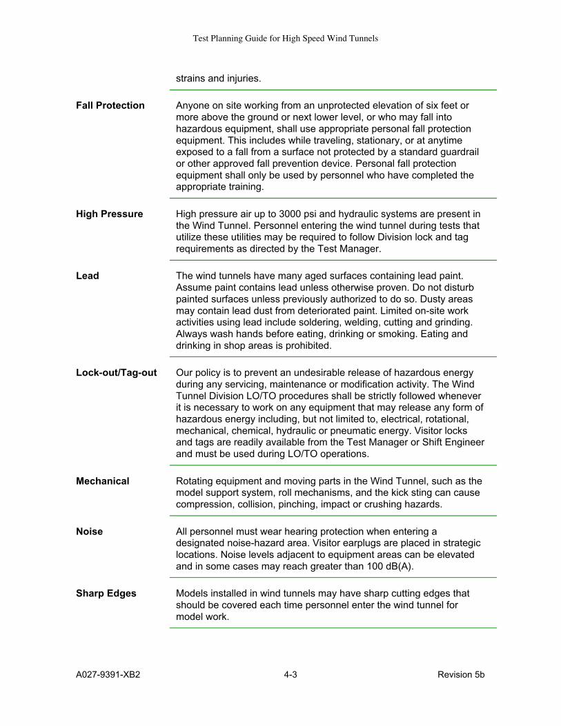
Fall Protection Anyone on site working from an unprotected elevation of six feet ormore above the ground or next lower level, or who may fall intohazardous equipment, shall use appropriate personal fall protectionequipment. This includes while traveling, stationary, or at anytimeexposed to a fall from a surface not protected by a standard guardrailor other approved fall prevention device. Personal fall protectionequipment shall only be used by personnel who have completed theappropriate training.
High Pressure High pressure air up to 3000 psi and hydraulic systems are present inthe Wind Tunnel. Personnel entering the wind tunnel during tests thatutilize these utilities may be required to follow Division lock and tagrequirements as directed by the Test Manager.
Lead The wind tunnels have many aged surfaces containing lead paint.Assume paint contains lead unless otherwise proven. Do not disturbpainted surfaces unless previously authorized to do so. Dusty areasmay contain lead dust from deteriorated paint. Limited on-site workactivities using lead include soldering, welding, cutting and grinding.Always wash hands before eating, drinking or smoking. Eating anddrinking in shop areas is prohibited.
Lock-out/Tag-out Our policy is to prevent an undesirable release of hazardous energyduring any servicing, maintenance or modification activity. The WindTunnel Division LO/TO procedures shall be strictly followed wheneverit is necessary to work on any equipment that may release any form ofhazardous energy including, but not limited to, electrical, rotational,mechanical, chemical, hydraulic or pneumatic energy. Visitor locksand tags are readily available from the Test Manager or Shift Engineerand must be used during LO/TO operations.
Mechanical Rotating equipment and moving parts in the Wind Tunnel, such as themodel support system, roll mechanisms, and the kick sting can causecompression, collision, pinching, impact or crushing hazards.
Noise All personnel must wear hearing protection when entering adesignated noise-hazard area. Visitor earplugs are placed in strategiclocations. Noise levels adjacent to equipment areas can be elevatedand in some cases may reach greater than 100 dB(A).
Sharp Edges Models installed in wind tunnels may have sharp cutting edges thatshould be covered each time personnel enter the wind tunnel formodel work.

Test Planning Guide for High Speed Wind Tunnels
A027-9391-XB2 4-4 Revision 5b
Trips, Bumps, andFalls
The Wind Tunnels have high numbers of cords, cables, conduit, pipingand other obstructive structures. Take special care when maneuveringthrough close quarters and areas with equipment.
Wind Tunnel Entry Most portions of the wind tunnels including the test section, windtunnel circuit, and test section plenums, etc. meet the OSHA definitionof confined spaces, therefore, all entries into the wind tunnel arecontrolled by facility personnel. Access to the test section is usuallyallowed without special controls; however, access to other areasgenerally requires the application of locks or tags to secure the facility,equipment, or systems in a safe configuration. Work activities withinthe wind tunnel beyond the test section must be coordinated with andapproved by the Test Manager before work commences.
Working Alone The term "working alone" means that an individual is in a worklocation, environment, or situation that will prevent others fromobserving and communicating verbally with them unless steps aretaken to establish a means of remote communication. The primary riskof concern for those working alone is that they will become injured or illand will not be able to perform a self-rescue, or be able to summonrequired assistance. It is not practical or desirable to eliminate allinstances of working alone. For example, single individuals on flexibleschedules may work alone in offices or control rooms before or afterregular business hours, and craftsmen may conduct rounds whilealone on swing or grave shifts. However, steps must be taken in allinstances to ensure that Customer and facility personnel identify therisks posed by working alone, and manage them to an acceptablelevel. Personnel may not work alone when the activities they will beperforming or the environment they will be performing them in posehigher than normal risks. Examples of such activities include:
• Entering permit-required confined spaces.• Entering the wind tunnel plenums.• Entering the wind tunnel circuits.• Working in any wind tunnel test section.• Breaking connections on, or pressure testing hydraulic or
pneumatic systems with operational pressures exceeding 15-psig, excluding shop air and instrument air up to 140 psig inlines and not exceeding 1-inch in diameter.
• Conducting work where an individual may come in contact withun-insulated, energized electrical equipment or componentshaving a potential greater than 50-volts.
• Operating or conducting maintenance on unguardedequipment that poses mechanical, point of operation, ormechanical power transmission hazards, such as adjusting orperforming functional tests.
• Conducting work requiring the use of life-saving safetyequipment, such as personal fall-arrest or restraint equipmentand supplied air respirators.

Test Planning Guide for High Speed Wind Tunnels
A027-9391-XB2 4-5 Revision 5b
and supplied air respirators.• Using or working around unenclosed Class IV lasers.• Working with dangerous quantities of hazardous materials.
All instances requiring working alone shall be discussed with andapproved by the Test Manager.
4.3 Hazardous Materials
Definition Hazardous materials are defined as any materials having propertiesthat may result in risk or injury to health, destruction of life or facilities,or harm to the environment. Hazardous materials, as defined, include,but are not limited to, toxic, flammable, combustible, corrosive,asphyxiating, reactive, and explosive materials. Other hazardousmaterial examples are compressed gases, oxidizers, reproductivetoxins, carcinogens, irritants, and sensitizers.
Beryllium Alloys The machining, filing, sanding, and polishing of metal alloys containingBeryllium is strictly prohibited in all NASA Ames facilities.
Material SafetyData Sheets
The Customer must provide the Material Safety Data Sheets (MSDS)for all Customer-supplied hazardous material, regardless of quantity,at least 4 weeks prior to test date.
HazardousMaterial ApprovalProcess
The Test Manager shall provide the Division Safety Office with theCustomer’s proposed MSDSs 4 weeks prior to test date. The WindTunnel Division Safety Office shall approve proposed hazardousmaterials operations and procedures before work begins. The AmesSafety Office will be notified when a material that may present a hazardto persons or has the potential to harm the environment will beintroduced into the workplace. After approval, MSDSs shall bemaintained at the worksite during the duration of tests.
Labels As a minimum, all hazardous material containers must be legiblylabeled with the name of the chemical or product that it contains andthe hazards the material poses to personnel (such as toxic, corrosive,flammable, etc).
OperationsInvolvingHazardousMaterials
The basic premise for ensuring safety during any operation involvinghazardous materials is that the individuals involved have an adequateunderstanding of the specific:
• Hazards, warning signs, and symptoms• Precautions to be taken• Procedures for handling emergencies
Gaining this understanding must be accomplished before startingoperations and should be an important consideration in planning thework. This means that every operation must be thoroughly screenedfor safety, and all personnel must be made aware of the hazards,precautions, and procedures for handling hazardous materials andresponding to accidents and other emergencies before the proposedactivities begin.

Test Planning Guide for High Speed Wind Tunnels
A027-9391-XB2 4-6 Revision 5b
operations and should be an important consideration in planning thework. This means that every operation must be thoroughly screenedfor safety, and all personnel must be made aware of the hazards,precautions, and procedures for handling hazardous materials andresponding to accidents and other emergencies before the proposedactivities begin.
Customer-GeneratedHazardous Waste
Any waste generated by the Customer must be stored and labeledappropriately. The Customer shall remove their generated hazardouswaste from Ames unless prior arrangements are made with Ameswaste operations.
Spills Notify the Test Manager of any hazardous material spills immediately.If appropriate, 911 will be alerted for any reportable spill (potential riskto health or environment). Assist in evacuation and deny entry toaffected area. Small spills that are not reportable (no potential risk tohealth or environment) can be controlled without external assistance ifspill response materials and PPE are available and persons aretrained. Do not go beyond your level of competence.
4.4 Protective Equipment
General Customer personnel must be equipped with hearing protection, safetyglasses, safety shoes, appropriate gloves, and any other protectiveequipment justified by the nature of the work. Emergency eyewashfountains are located at each facility. The Customer shall providetraining necessary to perform their work with the protective equipmentin a safe manner.
4.5 Personnel Training
General Customer personnel are responsible for having the necessary trainingand knowledge to understand the job hazards and their controls. Priorto arrival, they shall be trained in all tasks involved in the Wind Tunnelproposed operations in which they may participate. Such training mayinclude Hazard Communication, Confined Space Entry, LOTO, FallProtection, Cranes, Aerial Lifts, Forklift, Lead Awareness, PPE, BackInjury Prevention, Laser, UV, and/or Electrical Safety. The WindTunnel Division Health & Safety Manual and the Ames Health & SafetyManual are excellent sources for additional information on trainingrequirements at this Facility.

Test Planning Guide for High Speed Wind Tunnels
A027-9391-XB2 4-7 Revision 5b
4.6 Laser Safety
Safety Standards The use of lasers at Ames is governed by the "Standard AmericanNational Standards Institute (ANSI) Z136.1 for the Safe Use of Lasers"and the Ames Health and Safety Manual, Chapter 8. The TestManager coordinate with Center personnel as required to assistCustomer personnel in meeting the requirements contained in thesedocuments.
ApprovalAuthority
The Ames Laser Safety Officer (LSO) must evaluate and approve alllaser installations and operations. Approval must be coordinatedthrough the Test Manager.
Authorized LaserCustomers
Authorized Laser Customers are responsible for compliance withsafety regulations in the operation of their equipment, and:• Are responsible for ensuring that personnel using lasers under
their supervision are properly instructed and trained (within thelast 2 years).
• Must establish and maintain a current list of all personnelauthorized to operate specific types of Class III and IV lasersunder their direction.
Safety Eye Wear Safety eye wear designed to filter out the specific wavelengthcharacteristic of the laser affords adequate protection only if properlyprescribed and utilized. Safety eye wear should be evaluatedperiodically to ensure its integrity. There should be assurance that eyewear designed for protection from specific lasers is not mistakenlyused with lasers of different wavelengths. The specific optical densityat appropriate laser wavelengths of the filter plate should be printed onthe eye wear.
RequiredOphthalmologicExam
All authorized personnel who work with Class 3b and Class 4 lasersshall have a base-line eye examination for visual acuity prior tobeginning work with a laser system.
4.7 Other Safety Guidelines
BloodbornePathogens
Be aware that if any injury or accident occurs, do not clean up bloodsince there may be a potential exposure to bloodborne pathogens.Notify your Test Manager or Shift Engineer immediately for assistance.
Equipment All equipment will be inspected prior to operation and tagged out ifdamaged.
Housekeeping There shall be no hazardous accumulations of combustible trash anddebris. Access must be maintained for all exits, electrical panels, andfire protection panels. Corridors and stairways shall be kept clear ofobstacles. Equipment and material will be stored in a stableconfiguration. Working and walking surfaces must be dry, smooth, andfree of clutter.

Test Planning Guide for High Speed Wind Tunnels
A027-9391-XB2 4-8 Revision 5b
fire protection panels. Corridors and stairways shall be kept clear ofobstacles. Equipment and material will be stored in a stableconfiguration. Working and walking surfaces must be dry, smooth, andfree of clutter.
Permits Any activities involving hot work (e.g., welding, cutting, burning,brazing), generating solvent vapors into the air, entering a confinedspace, or disposing of industrial waste water, must be permitted priorto activities. Contact the Test Manager for more information.
Postings All visitors shall abide by area signs and postings.
Storm Drains Nothing is allowed to pass through the storm drains but rain water.
Vehicles The speed limit on the Ames Facility is 25 mph unless otherwiseposted. Ames Security is responsible for enforcing federal and statedriving laws. Vehicles shall be parked only in authorized parkingspaces.
4.8 References
The following Ames documents contain further information onenvironmental, health and safety issues.
• SOPs—Each wind tunnel has documented Standard OperatingProcedures that contain safety and emergency shutdown procedures
• Division and Branch Safety Plans—General safety procedures andguidelines
• Division Environmental SOP—Environmental procedures and policy• Building Emergency Actions Plan (BEAP) for the building being
occupied located in each lobby• Division Health & Safety Manual is available through the Division’s
external web page at http://windtunnels.arc.nasa.gov• Ames Health and Safety Manual (APR 1700.1)—Center parent
document on all safety issues at http://q.arc.nasa.gov/safetymanual/• "Standard American National Standards Institute (ANSI) Z136.1 for
the Safe Use of Lasers
Test Planning Guide for High Speed Wind Tunnels
A027-9391-XB2 5-1 Revision 5
5.0 Risk Assessment and Safety Review Requirements
Introduction
Wind tunnel testing inherently involves potential hazards that could affect personnel, equipment, or test progress.
Controlling these hazards is essential to ensuring personnel, equipment, and test operations are protected from harm and that the facilities operate to their fullest capacity. Therefore, model and associated equipment design and operation must incorporate safety principles presented in this document.
The Ames Health and Safety Manual describes procedures used to ensure equipment and systems are designed and operated safely.
5.1 Risk Assessment
Overview
The risk associated with conducting a test is a function of the hazard’s severity and the likelihood or probability that the hazard will actually be encountered.
The Ames Health and Safety Manual describes in general terms how the risk of hazards should be identified and mitigated. The Wind Tunnel Operations Division has further refined that process and adapted it to wind tunnel testing and operations as described in the following paragraphs.
The Customer is responsible for preparing the Risk Assessment, following guidelines presented in this document, and presenting the results of the assessment at the Initial Test Planning Meeting.
The Division may request, based on the Risk Assessment, that a Hazards Analysis be performed. This may be done by the customer or by the Division’s System Safety Analyst or a combination.
First, hazard severity is assessed, then probability, then these factors are considered together to determine the final risk. Finally, hazard controls are implemented to decrease or control the risk.

Test Planning Guide for High Speed Wind Tunnels
A027-9391-XB2 5-2 Revision 5
Hazard severity
There are four hazard-severity categories as described in the following table.
Hazard probability
There are four hazard-probability levels as described in the following table.
Table 5-1: Hazard-Severity Categories
Category Definition
I Catastrophic • Death or permanent debilitating injury• Possible tunnel down time in excess of three months• Possible equipment or facility damage above $500,000• Definite serious violation of operational criteria if test objectives
are to be met; waiver required
II Critical • Disfiguring injury or lost time greater than three months• Possible tunnel down time between one and three months• Possible equipment or facility damage between $50,000 and
$500,000• Possible serious violation of operational criteria if test objectives
are to be met
III Marginal • Lost-time injury greater than one day• Possible tunnel down time of less than one month• Possible equipment or facility damage between $10,000 and
$50,000• Operational criteria compromised in a minor way
IV Safe • No lost-time injuries• Tunnel down time less than one week• Possible equipment or facility damage less than $10,000• No violations of any operational criteria
Table 5-2: Hazard-Probability Levels
Level Description Probability of occurrence
A Probable—Likely to occur several times during the life of the system or test period
0.1 to 1.0
B Remote—Likely to occur once during the life of the system or test period
0.01 to 0.1
C Improbable—Not likely to occur during the life of the system or test period
0.001 to 0.01
D Highly improbable—Occurrence is considered to be extremely unlikely during the life of the system or test period
0.0 to 0.001

Test Planning Guide for High Speed Wind Tunnels
A027-9391-XB2 5-3 Revision 5
These risk severity categories and probabilities must be considered together to determine the final risk evaluation. Different levels of risk require different management approval, as described next.
Risk Assessment Approval
The matrix below shows who is responsible for authorizing the risk acceptance for each combination of severity and probability. These sign-off authority requirements apply to Test Readiness Reviews (TRRs), Operational Readiness Reviews (ORRs), and Hazard Reports that result from system safety analyses of test installations and facility modifications.
Hazard Controls
The Ames Health and Safety Manual describes the order of preference for controlling hazards. The Wind Tunnel Operations Division also implements controls for facility and test hazards following this order of preference, summarized as follows.
1. Design for Minimum Hazards—Provide inherent system safety by selecting appropriate design features and qualified components.
2. Incorporate Safety Devices—Includes mechanical barriers or inhibiting mechanisms. Conduct periodic functional checks of such safety devices.
3. Incorporate Protective Systems—Includes fire suppression systems, radiation shielding, flash shields, containment, etc.
4. Incorporate Warning Devices—Includes signals, lights, signs, horns, etc., and include requirements for training to ensure a proper and timely response to warning devices.
5. Institute Special Procedures—Include emergency procedures that effectively limit initiating a hazardous sequence. Includes caution and warning statements in normal operating procedures. A formal Operational Hazards Analysis will be required for all
Table 5-3: Risk Assessment Approval levels
Probability Level
A B C D
Hazard Category
Probable Remote Improbable Highly improbable
I Catastrophic Center DirectorII Critical
III Marginal FO Division
IV Safe FOO Branch

Test Planning Guide for High Speed Wind Tunnels
A027-9391-XB2 5-4 Revision 5
deviations from the Standard Operating Procedure (SOP) Manual for each facility.
5.2 Model Safety Requirements
Stress Report
A stress report is normally required for all models to be tested in the WInd Tunnel Operations Division facilities. See Section 5.3, Design Criteria-Reduced Requirements, and Section 5.5, Model Acceptance Criteria-Waivers, for limited exceptions to this requirement. The stress report establishes that the model has met all structural requirements. It should be complete and sufficiently comprehensive to preclude further explanation.
The Test Manager and customer personnel negotiate the delivery schedule for the stress report and other documentation at the Initial Test Planning Meeting. The report is due no later than 6 weeks prior to the tunnel entry date.
Stress Report Changes
Design evolution could dictate changing stress report content after decisions made at the Initial Test Planning Meeting. Negotiate changes with the Test Manager.
Stress Report Contents Overview
In the following order, the report must contain (as a minimum):
1. A table of contents.2. Documentation of load envelopes. Steady-state aerodynamic
loads and thermal loads for extremes of test conditions. Include starting loads for the 9x7ft wind tunnel.
3. A summary of the expected stresses and safety factors.4. A discussion of the sources of design loads and the methods
used to determine them.5. The stress analysis (see next section). 6. Drawings of the model configuration, support components, and
the model as installed in the tunnel.7. Quality-inspection reports to validate the integrity of the
completed model.8. Documentation of stability requirements (see section 5.3, Design
Criteria, for details on the stress analysis).9. Frequencies and estimated dynamic loads on model for dynamic
and transient testing.

Test Planning Guide for High Speed Wind Tunnels
A027-9391-XB2 5-5 Revision 5
Other Requirements
Ames might
also require other items such as:
• material certification• calibration data• dimensional certification• operator certification• detailed design drawings to validate the integrity of the
completed model• weld certification
These items are normally requested at the Initial Test Planning Meeting, if required.
Formal Design Review
Formal design reviews are not normally required of models to be tested in the Ames facilities. The Test Manager can, however, require design reviews for those designs that are especially complicated and potentially hazardous.
5.3 Design Criteria
Overview
This section describes design criteria, specifically:• Stress Analysis• Material Selection• Allowable Strength• Structural Joints• Pressure Systems• Electrical Equipment• Model Support Systems
Stress Analysis
Stress Analysis Overview
The stress analysis
must include, but is not limited to, the following elements:• An analysis showing that all models, including mountings and
emergency restraint systems, are statically and dynamically stable and free from divergence throughout the model test envelope (refer to Model Support Systems near the end of section 5.3).
• Aerodynamic derivatives used in the analysis, their source, and a discussion of the consideration given to effects of Reynolds number, Mach number, surface condition, etc.

Test Planning Guide for High Speed Wind Tunnels
A027-9391-XB2 5-6 Revision 5
• Source and range of mass and inertia parameters, including cross-coupling terms such as I
xz
and support-system stiffness coefficients.
• Parametric variations of significant design variables; i.e., tension-to-weight ratio, center-of-gravity location, pulley locations, etc., to establish sensitivity.
Stresses or Loads
Allowable stresses are the lessor of the material ultimate stress divided by a safety factor of 4, or the material yield stress divided by a safety factor of 3.
The stress analysis is to show that allowable stresses or loads are not exceeded for the worst load case, including but not limited to: • Dynamic factors that could result from separated flows in
wakes, on model surfaces or components, etc. • Thermal stresses due to factors such as cold or preheated air
used in some propulsion tests• Stress concentration factors• Wind tunnel starting loads• Maximum operating loads
Forces and Moments
Each detailed analysis section should contain a sketch showing forces and moments acting on the part and a statement of: • Assumptions • Approximations • Section properties • Type and heat treat condition of the material • Pertinent drawing number
General Equations
In all calculations, the general equations and their source must be given before substituting numerical values.
Air-Loaded Surfaces
Give shear and moment distribution diagrams resulting from worst-case pressure distribution.
Section Properties
Define section properties of the structural member for shear, axial load, bending, and torsion at an adequate number of stations to facilitate a check on the location of the designated critical sections.

Test Planning Guide for High Speed Wind Tunnels
A027-9391-XB2 5-7 Revision 5
Air Loads
All parts with lifting surfaces (such as vertical stabilizers, pylons, and struts) that are designed for operating only at zero angle of attack must be checked for air loads of ±2 degrees.
Static Test Instead of Stress Analysis
Static tests may be accepted in lieu of a stress analysis under the following conditions:
• If the load on the component in question can be directly and continuously monitored, the stress tests will be carried to twice the predicted operating load, and measured deflections must not indicate a permanent deformation. These tests must be witnessed by facility personnel.
• If the load on the component in question cannot be directly and continuously monitored (for example slats, ailerons, elevators, rudders, flaps), the static test must be carried to three times the predicted load without permanent set.
• Following static testing, nondestructive inspection techniques are required to validate the structural integrity of the component.
Gauged Components with Stress Analysis
If the load on the component in question can be directly and continuously monitored, a safety factor of three (3) or greater, calculated using the allowable tensile stress (F
tu
), is required in the stress analysis.
Reduced Requirements
If the model safety factors cannot be met (4.0 for ultimate and 3.0 for yield), contact the Test Manager to discuss the possibility of reducing (waiving) these requirements. Examples include tests of actual flight components, dynamically similar models, or aeroelastic models. Compensation for the safety factor reduction could include additional instrumentation, closely monitoring critical areas, provision of safety catches, or special proof loadings.
The provisions of this paragraph can only be implemented by waiver approval. See also section 5.5, Model Acceptance Criteria.
Previously Tested Components
Stress analysis must be submitted for all components to be tested in Ames facilities, even if they have been tested at Ames before. The customer must revise previous stress reports of previously tested models to incorporate any new worst-case loads for each component.

Test Planning Guide for High Speed Wind Tunnels
A027-9391-XB2 5-8 Revision 5
Material Selection
Materials Standards
Where applicable, materials are to be selected using mechanical properties and other specifications in the latest issue of one of the following standards:• ASTM Specifications• MIL-HDBK-5, Metallic Materials and Elements for Aerospace
Vehicle Structures. • MIL-HDBK-17, Plastics for Flight Vehicles
Mechanical Properties Corrections
All mechanical properties used must be suitably corrected for• Temperature • Pressure • Other environmental effects that might be present when the
material is under stress
Allowable Strength
Safety Factors
Except for gauged elements (previously discussed), safety factors of 4.0 on ultimate and 3.0 on yield must be maintained on parts and hardware. Plastic bending analysis is not accepted.
Refer to the Ames fastener guidelines later in this section. Also, if desired, contact the Test Manager for a current copy of the NASA Ames Research Center Fastener Supplier list.
Shear Stresses
If the shear ultimate strength of the material is unknown, calculate it as 60 percent of the tensile ultimate strength.
Thermal Stresses
Any thermal stresses that could occur must be algebraically subtracted from ultimate tensile and tensile yield strength of materials before the factors for allowable stresses are applied.
Material Properties
Material stress properties should reflect the expected minimums that will occur within the expected temperature range.
Buckling Stress
The allowable compressive stress in columns and skins must be equal to or less than one-third of the critical buckling stress.
Test Planning Guide for High Speed Wind Tunnels
A027-9391-XB2 5-9 Revision 5
Oscillating Stresses
Allowable oscillating stresses caused by oscillating loads with or without accompanying steady-state loads must be computed as follows:• The mean stress, if any, must be applied to the proper Modified
Goodman Diagram to which a safety factor of four (4.0) has been applied.
• The gross allowable oscillating stress must then be obtained from this diagram.
• The allowable oscillating stress must be obtained by dividing the gross oscillating stress by the appropriate stress concentration factor, if any.
Impact Strength
All material must have a minimum Charpy V impact strength of 15 foot-pounds at test conditions.
Structural Joints
Fastener Quality Standards
The models tested in theWind Tunnel Operations Division wind tunnels must be assembled using high-quality fasteners of SAE grade 5 or more.
Ames requires using certified fasteners; if used exclusively and proof of certification is supplied to the Ames Test Manager in the form of a Certified Material Test Reports (CMTR), no further checking will be required. If a CMTR cannot be provided, then all noncertified critical bolts will be removed from the model for examination and Rockwell hardness verification during test installation.
Fastener Assembly
Critical fasteners must be assembled using a calibrated torque wrench. The fastener manufacturer's torque specification will be used if the full-rated strength of the fastener is required to maintain Ames required safety factors.
Structural Joint Drawings
Drawings for all structural connections must list the following:• Strength and quality of fasteners• Torque values for tightening screws and nuts• All welded, soldered, brazed, bonded, or other nonbolted,
structural-connection techniques must be listed, showing locations on drawings and exact fabrication specifications, as well as analyzed in the stress report

Test Planning Guide for High Speed Wind Tunnels
A027-9391-XB2 5-10 Revision 5
Mil Spec Standards for Joints
Joining components (including tubing) by methods other than welding, soldering, or bonding is to be accomplished as appropriate in compliance with military specification standards.
All joints must be inspected using the appropriate nondestructive inspection technique decided upon by the customer and Ames personnel.
At NASA's discretion certain joint designs located at critical load-carrying sections might not be permitted. Soft-soldered joints are not acceptable. Silver-soldered joints might be acceptable, depending on application.
Welded Joints
All welded joints must be designed and fabricated in compliance with the code of the American Welding Society. All welds must be verified by appropriate inspection techniques such as, but not limited to, magnetic particle inspection, X-ray, or dye penetrant methods.
Critical welds (those whose failure would result in model or facility damage) must be analyzed in the stress report. Include inspection certification as an addendum to the stress report.
Shear Loads (bolted joints)
Shear loads must be transmitted by keys, pins, pilots, or shoulders.
Bolt Preload
For bolt preload in bolted structural joints: • Use manufacturer’s recommended value.• Avoid oscillating stresses in threads.
Thread Engagements
Critical fastener thread engagement with nuts and/or tapped holes must be sufficient to develop strength equal to the fastener or to the application design load with the appropriate safety factors applied.
Countersinks, Counterbores and Spot Faces
Model countersinks will be inspected during the test installation period to ensure that they are cut concentric to the threaded hole, have the proper countersink angle, and the fastener heads seat properly in the countersinks.
Counterbores and spot faces will likewise be inspected to verify that the contact surface does not bend or pry on the fastener body when

Test Planning Guide for High Speed Wind Tunnels
A027-9391-XB2 5-11 Revision 5
it is tightened.
Small Screws
Fasteners of size #4 or less that are removed during a model change must be replaced with a new fastener.
Screw Joints
To assure tight joints between parts joined by screws, screws and threaded connectors must be sufficiently torqued to provide loads greater than the expected maximum separating forces.
Bolted Joints
Bolted joints with the primary function of transmitting moments must be designed in such a manner that the bolt preload divided by the joint contact area is at least 1.25 times the applied moment divided by the section modulus of the contact area.
Any bolt torque values that are different from the published vendor data must be derived in the stress analysis.
Fastener Locking
All structural bolted or screwed connections must be provided with positive mechanical locks such as
:
• Locking inserts • Self-locking-type nuts • Safety wiring (drilled heads must be provided)• Fastener adhesive such as Loctite (within rated temperature)
All bolted and screwed connections must meet these requirements, even if the connection is to be repeatedly disassembled during testing (e.g., changes in flap deflections).
Pressure Systems
High-pressure Air Availability
Most Wind Tunnel Operations Division facilities can supply up to 3,000 psi heated air with various burst disk capacities.
Pressure-Relief Devices
Relief devices are required in the system (but not necessarily in the model) and must be capable of discharging the full flow of the pressure source under all conditions including those resulting from malfunctions.
Users are to inform the Test Manager on the requirements of the

Test Planning Guide for High Speed Wind Tunnels
A027-9391-XB2 5-12 Revision 5
maximum and minimum pressures the model can withstand to determine system burst disk pressures. Users must provide pressure relief devices appropriate to the model as required. If rapid air discharge constitutes a noise hazard, mufflers are required on discharge lines.
Users should check with the Test Manager to verify the appropriate burst disks are available; otherwise customers must supply their own.
Pressure System Codes
Models, support equipment, and test equipment using hydraulic, pneumatic, propulsion, or other systems with operating pressures above 15 psig are to be designed, fabricated, inspected, tested, and installed to comply with the following codes and definitions:• ASME Boiler and Pressure Vessel Code• ASME B31.1 Power Piping Code• ASA Codes as sponsored by ASME• Department of Transportation Regulations
Pressure System Components
Definition
The components of a pressure system include• vessel• relief devices• piping
Testing/Storage
Pressure components that have been proof-tested must be stored in a clean, dry, sealed condition with controlled accessibility.
Identification
All pressure system components (including piping) are to be indelibly marked in a conspicuous place with sufficient information to determine: • Part number • Proof test pressure • Working pressure • Date of proof test • Volumes and temperature range
Certification
All pressure system components must have current certification

Test Planning Guide for High Speed Wind Tunnels
A027-9391-XB2 5-13 Revision 5
(valid throughout the test). Certifications are required annually. A certification report must be submitted for all tested systems.
Pressure Vessel
Definition
All shells, test chambers, tanks, and model parts designed for internal pressures greater than 15 psig are considered pressure vessels.
Design
Pressure vessels must be designed in compliance with the latest edition of the ASME Boiler and Pressure Code, Section VIII or Section III.
Welding
Pressure-vessel welding must be in compliance with the ASME Boiler and Pressure Code as follows:
• Section IX for welding qualifications• Section V for welding inspection
Pressure Piping
All piping must be designed, fabricated, inspected, tested, and installed in compliance with the latest edition of the ANSI Standard Code for Pressure Piping.
Tubing to Powered Models
For powered models, the internal supply tubing is considered pressure piping.
Piping in Pressure Vessels
Pressure vessels fabricated from standard pipe, standard pipe fittings, and standard flanges are also considered pressure piping. They are defined as those covered by these ANSI dimensional standards
:
• Pipe: B.36.10 and B.36.19• Fittings: B.16.9• Flanges: B.16.5
WeldingWelders, welding operations, and welding procedures are to be qualified in compliance with Section IX, ASME Boiler and Pressure Vessel Code, except as modified by the applicable section of the Piping Code.

Test Planning Guide for High Speed Wind Tunnels
A027-9391-XB2 5-14 Revision 5
ThreadingAllowances must be made as required or recommended by the Piping Code for pipe threading, corrosion, and wall thinning due to pipe bending.
Threaded Pipe JointsThreaded joints, flange joints, and seal welding of threaded joints must be in compliance with the requirements and recommendations of the Piping Code.
Tube FittingsTube fittings must be in compliance with the latest issue of applicable Military Standards.
Service Line IdentificationAll service lines must be properly identified for working pressures, flow direction (in or out), and fluid or gas carried.
Electrical Equipment
General All electrical devices and wires used in the test section must be capable of withstanding the test section environment.
Material Criteria Use only qualified hardware or equipment and material conforming to the National Electrical Code. Wires and cable require good abrasive resistance. All wiring is to be identified in accordance with schematic and wiring diagrams by using color coding, bands, tags, etc.
Fuses and Shielded Wires
Protect electric circuits with proper fuses. Pressure transducers, strain gauges, vibration pickups, and other low-voltage devices should have each set of wires shielded. Also use shielded wiring with high-voltage and AC devices. Determine the required size, type, and length of wiring at the pretest conference.
User-Furnished Electrical Materials
The customer should provide the following electrical devices as discussed at the Initial Test Planning Meeting and required by the test. • Control panels and/or control boxes required to operate model
components.• Control panel leads of sufficient length to make proper
connections in the respective control rooms.

Test Planning Guide for High Speed Wind Tunnels
A027-9391-XB2 5-15 Revision 5
• Mating electrical connectors for any customer-furnished equipment requiring connectors at interfaces located at control boxes in and/or at the model.
• Electrical schematics, wiring diagrams, and hookup sheets for model and control panels with the model design drawings in compliance with documentation requirements.
Documentation should be provided to the Test Manager 4 weeks before the start of the test.
Model Support Systems
Specification An adequate margin of bending and torsional stability must be shown for models and model support systems and must meet the following divergence criteria:
For all test conditions and configurations, the ratio of model airload increase due to a change in angle of attack (dN/dα) to the support system restoring force generated by such an angle change (dFss/dΘ) must not exceed one-half.
Aerodynamic Interference
The customer, after consulting the Test Manager, is responsible for providing a design that reduces aerodynamic interference to minimum acceptable limits, including models to be tested on Ames-furnished stings.
Model Support Hardware
Any customer-supplied hardware must be fit-checked and forwarded to Ames for verification at least 6 weeks before the test date. Taper fits must have at least 80 percent evenly distributed contact on each land. A report of fit-check results must accompany the hardware (see Appendices A, B and C). Taper fits will be verified at Ames using the fluorescent oil technique described in Appendix A.
If customer hardware is to match with Ames gauges, the gauge(s) will be provided at the customer's request by the Ames Test Manager.
dN/dαdFss/dΘ <1/2

Test Planning Guide for High Speed Wind Tunnels
A027-9391-XB2 5-16 Revision 5
An inventory of model support hardware available at Ames is listed in Appendix B.
5.4 Model Fabrication Requirements
General The customer is responsible for having models fabricated and assembled in compliance with:• Design drawings and specifications• Model safety requirements (see section 5.2)• Design Criteria (see Section 5.3)• Inspection and tests established by the Test Manager (see
Section 5.5)
Model Assembly Models are to be completely assembled for all test configurations at the manufacturer's plant and discrepancies corrected before shipment to ensure that:• All model parts fit properly.• Model loading fixtures have proper fit and have been certified
for the required loads.• All remote-controlled model components function properly.• All position indicators can be calibrated.• Sufficient clearances are provided for differential deflections
due to air loads.• All leads are identified.• All pressure lines are clean, free of oil and debris, and are leak-
checked at operating pressures.• All required inspections and certifications have been performed
and documented (welds, concentricity, etc.).

Test Planning Guide for High Speed Wind Tunnels
A027-9391-XB2 5-17 Revision 5
5.5 Model Acceptance Criteria
Model Acceptance Model acceptance for testing in the Wind Tunnel Operations Division facilities is contingent upon satisfaction of the requirements presented in section 5.2 through section 5.4, in addition to the requirements listed below.
Inspections The customer must be prepared to provide inspection reports (records, inspection reports, and test results) for defining and verifying the quality of the model throughout all operations, including:• Procurement • Fabrication • Test • Delivery
The inspection report requirements are set by the Test Manager and will be provided for the customer at the Initial Test Planning Meeting. Typical reports required include the results of non-destructive weld examiniations and fastener/material certifications.
Structural Reports The customer must provide:• Any reports of inspections and tests of all materials by
chemical or physical means to verify compliance with applicable drawings and specifications.
• Any written procedures, or other controls, over processes used to assure uniform quality of articles or materials..
• Documentation of all articles and materials that do not conform to applicable drawings, specifications, or other requirements.
Waivers Requests for deviations from the requirements outlined in this document must be submitted in writing at the earliest possible time. The preferred time for waiver submission is at the Initial Test Planning Meeting. However, events in the model fabrication process may move the submittal of a waiver closer to the actual test time.
The Deviation Waiver request should include:• Full justification for the waiver with supporting data and
analysis.• Previous test data of the same model in other facilities if
applicable.

Test Planning Guide for High Speed Wind Tunnels
A027-9391-XB2 5-18 Revision 5
The following process is used for waiver approval:• The Test Manager is responsible for the disposition of all
submitted waiver requests.• Waivers will be processed within four weeks of submittal to the
Test Manager.• The waiver will be analyzed and reviewed at a specially called
Test Safety Review (A detailed explanation of Test Safety Reviews can be found in the Wind Tunnel Operations Division Test Process Manual.
• The customer will be apprised of the results of the Test Safety Review which will include acceptance, rejection, or required modifications to the waiver.
Test Planning Guide for High Speed Wind Tunnels
A027-9391-XB2 6-1 Revision 5
6.0 General Test Support Systems
Description
This section discusses these available test support systems:• High-Pressure Air• Hydraulic System• Separation Support System• Roll Adapter
6.1 High-Pressure Air
Description
High-pressure air (3,000 psi) is available at most of the Wind Tunnel Operations Division facilities.
In the 9x7ft, 11ft, and 12ft wind tunnels, a digital-valve system is installed for high-pressure air. Flow rates can be set in increments of 0.01 pounds per second and is repeatable to 0.02 pounds per second. An outlet pressure control mode is also available with a tolerance of ±2% of set point.
See section 7 for more details on the available mass flow for the other facilities.
Air Pumping and Storage Capacities
The pumping plant consists of three compressor systems having capacities of 8, 8, and 10 pounds per second, respectively, for a combined capacity of 26 pounds per second at 3,000 psi. The current storage capacity consists of 7.8 million standard cubic feet at 3,000 psi.
Air Heaters
Electric heaters (rated at 1.0 megawatt each) are available for heating high-pressure air. The heaters are made of four, equal-capacity resistive elements and are rated for 3,000 psi. The maximum heater outlet temperature is 400° F.
Low Air Heater Flows
The air heater controls may prohibit heater operation at very low air flows (below 0.5 lb/sec). For tests requiring low air flows or when preheated air lines are desired, it might be necessary to consult with a Test Manager for a particular facility.

Test Planning Guide for High Speed Wind Tunnels
A027-9391-XB2 6-2 Revision 5
Facilities Available for Heater Setup
Each of the following Wind Tunnel Operations Division facilities are set up for installation of heaters. • 9x7ft Supersonic Wind Tunnel • 11ft Transonic Wind Tunnel • 12ft Pressure Wind Tunnel
Propulsion Simulator Calibration Laboratory
The Propulsion Simulator Calibration Laboratory has its own set of four banks of heaters that are rated at 225 kilowatts each. The maximum operating pressure is 3000 psi, and maximum output temperature is 400˚ F.
6.2 Hydraulic Systems
Portable Systems
Three portable hydraulic systems are available for use in any of theWind Tunnel Operations facilities. The supply capabilities of each system are as follows.
• 10.4 gallons per minute at 5,000 psi• 10.7 gallons per minute at 3,000 psi• 15.0 gallons per minute at 1,500 psi
Unitary Model Prep Rooms
The model preparation rooms in the Unitary Plan Wind Tunnels are equipped with permanent hydraulic systems capable of supplying 100 gallons per minute at 3,000 psi. All systems use MIL-H-5606 or DTE 25 oil.
6.3 Separation Support System
Angular Displacement
The system allows testing of two separating models. Angular displacement of the separation support system in the vertical and horizontal planes is provided by the respective wind tunnel support system. The separation support system provides displacement of the secondary model relative to the primary model.

Test Planning Guide for High Speed Wind Tunnels
A027-9391-XB2 6-3 Revision 5
Available Facilities
The manually controlled separation support system adapts to the tunnel strut system in the following facilities (also refer to section 7): • 9x7ft Supersonic Wind Tunnel • 11ft Transonic Wind Tunnel
Maximum Displacement Capability
The maximum displacement capability of the system is:
Contact the Test Manager for any additional needs.
Load Limits
The load limits for both the primary and secondary models are 78,000 inch-pounds about the attachment of the stings to the separation support system.
6.4 Roll Adapters
Available Facilities
Two electrically driven, remotely controlled roll adapters are available for tests in the following facilities: • 8x7ft Supersonic Wind Tunnel • 9x7ft Supersonic Wind Tunnel • 11ft Transonic Wind Tunnel
Availability and use of either of these adapters must be coordinated with the Test Manager.
The 12ft Pressure Wind Tunnel has its own roll mechanism system. See section 7.4.
Axial displacement 9 inches
Horizontal displacement 10 inches
Vertical displacement 14 inches
Vertical angle displacement ±16 degrees
Lateral angle displacement ±6 degrees

Test Planning Guide for High Speed Wind Tunnels
A027-9391-XB2 6-4 Revision 5
Capacities
The roll adapters are 40 inches long and adapt to the primary strut support system in each of the above wind tunnels. The adapters are capable of 357 degrees of roll. The rolling moment is ±25,000 in-lbs.
The roll mechanism is capable of handling the loads and moments of the model support system. See section 7 for more information on individual model support systems.

Test Planning Guide for High Speed Wind Tunnels
A027-9391-XB2 7-1 Revision 5a
7.0 Description of Test Facilities
Facilities The facilities discussed herein are under the jurisdiction of the Wind Tunnel Operations Division of Ames Research Center. These facilities consist of three, closed-circuit, continuous-flow, wind tunnels.
Unitary Plan Wind Tunnels
The Unitary Plan Wind Tunnels are a set of three interconnected tunnels that share a central main drive system that can be used to drive either a transonic leg or a supersonic leg. The Unitary Plan Wind Tunnels are as follows.• 11-by 11-Foot Transonic Wind Tunnel • 9-by 7-Foot Supersonic Wind Tunnel
Other Tunnels The other high speed wind tunnel facility is the 12-Foot Pressure Wind Tunnel.
7.1 11ft Transonic Wind Tunnel
Description The 11-by 11-Foot Transonic Wind Tunnel is a closed-return, variable-density tunnel with a fixed-geometry, ventilated test section, and a dual-jack flexible nozzle.
The test section has 5.6 percent porosity consisting of evenly distributed slots on all four walls.
Air flow is produced by a three-stage, axial-flow compressor powered by four, wound-rotor, variable-speed, induction motors.
Operating Characteristics
The operating characteristics of the 11-by 11-Foot Transonic Wind Tunnel are presented in the following graph. The ranges of the pertinent performance characteristics are:
Mach number (continuously variable) 0.20 to 1.50
Stagnation pressure 3.0 to 32.0 psia
Reynolds number 0.3x10⁶ to 9.6x10⁶/ft
Maximum stagnation temperature 610°R
Strut angle of attack range nominally ± 15°

Test Planning Guide for High Speed Wind Tunnels
A027-9391-XB2 7-2 Revision 5a
Figure 7-1: 11ft Transonic Wind Tunnel Operating Characteristics

Test Planning Guide for High Speed Wind Tunnels
A027-9391-XB2 7-3 Revision 5
Test Section Dimensions
Pertinent test section dimensions are:
Figure 7-2: 11ft Transonic Wind Tunnel Test Section Dimensions
Height 11.0 ft
Width 11.0 ft
Length 22.0 ft
Access hatch, top: 11.0 x 22.0 ft
Side doors: 3.0 x 4.9 ft
AIR FLOW
14.00 ft
3.00ft
TRAVERSING STRUT
α RANGE + 15°
END OF TEST SECTION
2.99 ft10.52ft
L
TEST REGION
100 165 220 264 TEST SECTION STATIONS IN INCHES
0.30 ft
WINDOWS IN PRESSURE SHELLAND TUNNEL SIDE WALL
TYPICAL TRAVELOF MODEL CENTER OF ROTATION
8.17 ft
for β = 0 °
3.96 ft
CENTER OF ROTATION
4.16 ft
11.00 ft INS
IDE

Test Planning Guide for High Speed Wind Tunnels
A027-9391-XB2 7-4 Revision 5
Model Installation Diagram
This diagram shows a sting installed with a 40-inch extension.
Figure 7-3: 11ft Transonic Wind Tunnel Sting Installation
Forward and Aft Limits
The forward and aft limits of the model location in the test section are dependent on the Mach number and the type of data required. As identified by tunnel station:
Consult the Test Manager for any deviations from these limits.
Location ofTop Hatch
Recommended Most Aft Locationof Model (See Section 9.1.3)
Sta175
264
Tunnel Ceiling
82.85
Optional40 in. Ext.
Center of Rotation
Vertical Strut
End of Test Section
Sta165
126.24
Tunnel Floor
Load Comp.Cable Positions
49.9
Distance From Model Support C.R.
Tunnel Station, in.
NOTE: All dimmensions are in inches
180 160 140 120 100 80 60 40 20 0
180160140120100 200 220 240 260 280
CL Of Windows
Table 7-1: 11ft Transonic Wind Tunnel Model Location Limits
Station Limit
175 Aft limit for subsonic drag performance testing
193 Aft limit for subsonic static stability and control testing
220 Aft limit for supersonic static stability and control testing
60 Forward limit for subsonic testing
100 Forward limit for supersonic testing

Test Planning Guide for High Speed Wind Tunnels
A027-9391-XB2 7-5 Revision 5a
Forces and Moments
A traversing strut downstream of the test section can be programmed to translate vertically to maintain a desired point of model-pitch rotation throughout the vertical plane angle-range. The model support center-of-rotation in the horizontal plane is 4.8 inches aft of the strut leading edge. These angles are continuously variable and are determined by the relative positions of a knuckle and sleeve inside the support body.
The model support system can position the model at attitudes circumscribed by a 15-degree half-angle cone. Bent primary adapters of 5, 10, 12.5, and 20 degrees are available to alter the range of model angles. Forces and moments about the model support center of rotation are limited to:
Load Compensation A load compensation system capable of exerting a downward force of up to 8,000 lbs over a vertical travel range of 51 inches is available at tunnel stations 215.8 or 239.4. This system is used to offset high-lift forces which would otherwise exceed the design-load limits of the strut.
Turntable Model Support
A subfloor-mounted turntable model support, used primarily for semispan model testing, is located at tunnel station 106. This support system can be rotated ±180 degrees and forces and moments are limited to:
Vertical ±8,000 lbs
Lateral ±4,000 lbs
Axial ±3,000 lbs
Rolling moment ±104,000 in-lbs
Combined vertical and lateral bending moment
±800,000 in-lbs
Lateral force (at a height of up to 24 inches above the floor):
±50,000 lbs
Torque (about axis of turntable): ±500,000 in-lbs

Test Planning Guide for High Speed Wind Tunnels
A027-9391-XB2 7-6 Revision 5a
Semispan Testing Provisions are available for sealing the slots in the test section floor to provide a solid image plane for semispan testing.
Installation and Personnel Access
Models can be installed through a hatch in the top of the test section. Personnel gain access to the test section through doors in the diffuser sidewalls downstream of the model support strut.
Flow Visualization Flow visualization techniques are available through multiple, optical-quality windows in the tunnel sidewalls. Optical-quality windows are also available in the test section ceiling and floor.
High-Pressure Air High-pressure air (3,000 psi) is available at weight flows to 80 pounds per second through dual, independently regulated lines ending within the support strut. A one-megawatt, moveable heater can preheat air from one of these lines. Preheated air at 60 pounds per second is available at the turntable.
7.2 9-by 7-Foot Supersonic Wind Tunnel
Description The 9-by 7-Foot Supersonic Wind Tunnel is a closed-return, variable-density tunnel equipped with an asymmetric, sliding block nozzle.
The test section Mach number can be varied by translating, in the streamwise direction, the fixed contour block that forms the floor of the nozzle.
Airflow is produced by an 11-stage, axial-flow compressor powered by four variable-speed, wound-rotor, induction motors.
Operating Characteristics
Pertinent performance characteristics are:
Mach number (continuously variable)
1.54 to 2.56
Stagnation pressure 4.4 to 29.5 psia
Reynolds number 0.9x10⁶ to 6.5x10⁶/ft
Maximum stagnation temperature
600°R

Test Planning Guide for High Speed Wind Tunnels
A027-9391-XB2 7-7 Revision 5a
Figure 7-4: 9x7ft Supersonic Wind Tunnel Performance Characteristics

Test Planning Guide for High Speed Wind Tunnels
A027-9391-XB2 7-8 Revision 5
Test Section Dimensions
Pertinent test section dimensions are:
Figure 7-5: 9x7ft Supersonic Wind Tunnel Test Section Dimensions
Height 7.0 ft
Width 9.0 ft
Length 18.0 ft
Access Hatches
Removable Ceiling Panel: 6.0x9.0 ft
Side door: 3.0x6.5 ft
Traversing Strut
2.333
2.042
9.00 ftInside
Sting Body
PLAN VIEW
Range ±15For = 0
αβ
1.25
3000-psi Air Outlets2-1/2 in. NPT (both sides)
28.2 diam Schlieren Windows
7.00 ftInside
Areas Covered by Rotatable Windows 50.8 Diameter
Range ±15For = 0α
β
ELEVATION VIEW
Model SupportCenter of Rotation
63.766.0
NOTE: All dimensions are in inches unless otherwise noted

Test Planning Guide for High Speed Wind Tunnels
A027-9391-XB2 7-9 Revision 5
Model Installation Diagram
Model installation is normally accomplished through a 3x6.5-foot door in the north wall of the diffuser. Under special circumstances the model may be installed through the 6x9ft ceiling panel.
Figure 7-6: 9x7ft Supersonic Wind Tunnel Model Installation
Model Support System
A traversing strut downstream of the test section can be programmed to translate horizontally to maintain a desired point of rotation throughout the horizontal-plane angle-range, generally angle-of-attack.
The center of rotation in the vertical plane is 5.3 inches aft of the strut leading edge. The horizontal and vertical plane angles are continuously variable and are determined by the relative positions of a knuckle and sleeve inside the support body. The model support system can position the model at attitudes circumscribed by a 15-degree half-angle cone.
Bent primary adapters of 5, 10, 12.5, and 20 degrees are available to alter the range of model angles.
84
80 60 140 120 00 0 0 0 20
6 63.75
72
OCATION OFTOP HATCH
26.87
41.84
CENTER of ROTATION
28.2clearview)
80 160 40 120 00 80 0 0 20
0.003.75129.75
TUNNEL STATION, in.
ALL DIMENSIONS ARE IN INCHES
or and α β

Test Planning Guide for High Speed Wind Tunnels
A027-9391-XB2 7-10 Revision 5
Forces and Moments
Forces and moments about the model support center of rotation are limited to:
Flow Visualization
Schlieren and other flow visualization techniques can be obtained by appropriately positioning 2.35-foot diameter optical-quality windows in the test section sidewalls.
High-Pressure Air
High-pressure air (3,000 psi) is available at weight flows up to a total of 80 pounds per second through dual, independently regulated lines. Air from one of these lines can be preheated using a one megawatt moveable heater.
Reflected Shock Waves
Shock waves reflecting on the model from the solid test section walls can have a significant effect on the model forces and pressures. To calculate the location of this reflected wave, assume it is reflected at the Mach angle from a 4-inch thick wall boundary layer.
Starting Loads
The design of models to be tested in the 9x7ft Supersonic Wind Tunnel must allow for additional critical conditions associated with blockage (the ratio of model-projected frontal area to test section cross-sectional area) and transient starting loads. Large model blockages provide a potential to “unstart” the airflow, allowing a strong shock wave to pass through the test section resulting in possible damage to the model, sting and balance.
Normal procedure is to reduce the tunnel pressure and position the model for minimum loads before beginning the acceleration to, or deceleration from, supersonic conditions.
However, significant transient loads are still generated by the swirling, subsonic, separated flows preceding the establishment of sonic velocity in the upstream throat. To ensure that a model, sting
Lateral ±8,000 lbs
Vertical ±4,000 lbs
Axial ±3,000 lbs
Rolling moment ±104,000 in-lbs
Combined vertical and lateral bending moment
±800,000 in-lbs

Test Planning Guide for High Speed Wind Tunnels
A027-9391-XB2 7-11 Revision 5
and balance will withstand these transients, they must be designed to withstand the empirically derived starting loads indicated in the following charts.
Figure 7-7: 9x7ft Supersonic Wind Tunnel Load Locations
Figure 7-8: 9x7ft Supersonic Wind Tunnel Starting Loads
∂
STARTING LOADS APPLY IF1.25 IS NOT EXCEEDED∂
∂ = DISTANCE BETWEEN SIDE FORCE GAUGES
FS
FN
x
SIDE AREA = 1.91 ft2
PLANFORM AREA = 3.05 ft2
APPLY BALANCE GAUGE LOADSDIRECTLY OVER EACH GAUGE
USE THE CENTROID OF PROJECTEDPLANFORM AREA FOR THE RESULTANTLOAD LOCATION FOR BOTH VERTICALAND HORIZONTAL MOUNTING
EXAMPLE 1. MODEL MOUNTED VERTICALLY
MODEL AND STING LOAD
SIDE FORCE LOAD
NORMAL FORCE LOAD,
NF = (175)(3.05) = 534 lb
MOMENT, Mx = NS2 2F F+ x = 783 x
INDIVIDUAL BALANCE GAUGE LOAD
NORMAL FORCE LOAD, EACH GAUGE
SIDE FORCE LOAD, EACH GAUGE,
SF = (375)(1.91) = 716 lb
NF = (210)(3.05) = 641 lb
SF = (300)(1.91) = 573 lb
EXAMPLE 1. MODEL MOUNTED HORIZONTALLY
MODEL AND STING LOAD
SIDE FORCE LOAD
NORMAL FORCE LOAD,
=
INDIVIDUAL BALANCE GAUGE LOAD
NORMAL FORCE LOAD, EACH GAUGE,
SIDE FORCE LOAD, EACH GAUGE,
MOMENT, Mx NS2 2F F+ x = 626 x
NF = (280)(3.05) = 854 lb
SF = (90)(1.91) = 172 lb
NF = (200)(3.05) = 610 lb
SF = (75)(11.91) = 143 lb
STARTING LOADS
MODEL ORIENTATION
VERTICAL PRIMARY LIFTING SURFACES:
SIDE FORCE (VERTICAL DIRECTION)NORMAL FORCE (HORIZONTAL DIRECTION)
HORIZONTAL PRIMARY LIFTING SURFACES:
SIDE FORCE (HORIZONTAL DIRECTION)NORMAL FORCE (VERTICAL DIRECTION)
MODEL AND STINGLOADS, lb/ft2
INDIVIDUAL BALANCE
GAUGE LOADS, lb/ft 2
WINGEDMODELS
BODYALONE
BODYALONE
WINGEDMODELS
75 150 90 150200 200 280 200
300 200 375 200175 150 210 150

Test Planning Guide for High Speed Wind Tunnels
A027-9391-XB2 7-12 Revision 5
7.3 12ft Pressure Wind Tunnel
Facility Description
The 12ft Pressure Wind Tunnel is a closed-return, variable-density, low-turbulence, subsonic wind tunnel.
Customers can test models on four different support systems with duplicates of these systems in two model preparation rooms to expedite model build-up, check-out, and installation.
Figure 7-9: 12ft Pressure Wind Tunnel General Layout
Operating Characteristics
The ranges of pertinent performance characteristics are as follows.
Continuous Airspeed: Mach No. 0.05 to 0.55Total Pressure: 0.2 to 6.0 atmospheres, absoluteCore Flow Quality (tunnel empty):
Integrated flow angularity
≤
0.02°Longitudinal turbulence
≤
0.05%Lateral turbulence
≤
0.2%
NASA Ames Research CenterAccess Mode
Inlet Guide Vane
Fan Blades
Exit Guide Vanes Motor15,000 HP
Wide Angle Diffuser Screens
Heat ExchangerTurbulence Reduction Screens
Test Section
Access Valve
Model Support
Isolation Valve
Run Mode
NASA Ames Research Center
Make-Up AirCompressor
12ft Pressure Wind Tunnel
Personnel Door

Test Planning Guide for High Speed Wind Tunnels
A027-9391-XB2 7-13 Revision 5
Temperature variation less than 1°F across test section
Figure 7-10: 12ft Pressure Wind Tunnel Operating Characteristics
Airflow
Airflow is produced by a single-stage fan powered by a 15,000-hp, variable-speed synchronous motor with a solid-state, variable-frequency speed controller.
The single-stage main-drive fan has 20 fixed-pitch aluminum

Test Planning Guide for High Speed Wind Tunnels
A027-9391-XB2 7-14 Revision 5
blades, 19 variable-camber inlet guide vanes with 50%-chord trailing edge flaps, and 15 fixed-camber exit guide vanes.
Settling Chamber
The settling chamber is designed to provide a very low-turbulence airstream. It contains a fin/tube heat exchanger (four tubes deep), one coarse-mesh screen (three 0.080" diameter wires per inch) and five fine-mesh screens (ten 0.020" diameter wires per inch). The area contraction ratio between the settling chamber and the test section is 21:1.
Test Section
The test section has a circular cross section with four 4-foot-wide flat surfaces centered about the horizontal and vertical centerlines. The width and height is 11.3 feet (between the flats), and the length is 28 feet.
Three 2x4ft optical-quality windows are available for wall and ceiling areas. Plastic (Lexan)or ultraviolet transparent acrylic windows or steel blanking plates are available for the remaining window spaces.
Test Section Isolation System
For efficient operation, the test section design permits access while the circuit is pressurized. The entire test section is mounted in a plenum on a carousel that rotates 90° about the vertical axis between the run and access positions.
While running, the test section is aligned with the tunnel circuit. When model access becomes necessary with the circuit pressurized, operators rotate the carousel 90°. The two circuit-to-plenum isolation valves are then locked in place and the plenum can be depressurized to atmosphere. Test section entry is through either the large plenum-access valve or the smaller personnel doors. It takes approximately 10 minutes to access the test section when the circuit is at 6 atmospheres.

Test Planning Guide for High Speed Wind Tunnels
A027-9391-XB2 7-15 Revision 5
Model Support Systems
Four model support systems are available:
Turntable Model Support (TRN)
The TRN is a variable-yaw support mounted in the floor of the test section. The TRN includes a lift platform for mounting the bipod (BMS) and a sector-type carriage and track for mounting the high angle- of-attack (HAA) strut. The TRN can also be adapted for semispan model testing.
Bipod Model Support (BMS)
The BMS is a vertical pylon-type support mounted to the TRN lift platform. The BMS provides variable-pitch capability, which can be combined with the vertical-translation capability of the TRN lift platform and the variable-yaw capability of the TRN.
High Angle of Attack (HAA)
The HAA model support is a variable pitch and roll system mounted to the TRN and uses the variable-yaw capability of the TRN. The pitch range is achieved in two steps: from -5° to 65° and from +25° to +95°. Roll changes are made at reduced wind speeds.
Table 7-2: 12ft Pressure Wind Tunnel Turntable Design Characteristics
Operating Limits
Design Loads
Yaw +166.5°-191.4°
Normal (crossstream)
±40,000lbs P. Mom. (about vertical axis)
±300,000 in-lbs
Axial (streamwise)
±10,000lbs R. Mom. (about horizontal axis)
±2,280,000 in-lbs
Table 7-3: 12ft Pressure Wind Tunnel Bipod Design Characteristics
Operating Limits Design Loads
Pitch -15° to +45° Normal ±12,000lbs P. Mom. ±84,000 in-lbs
Yaw +166.5°-191.4°
Axial ±3,000lbs Y. Mom. ±42,000 in-lbs
Vertical ±20 in. Side ±6,000lbs R. Mom. ±30,000 in-lbs

Test Planning Guide for High Speed Wind Tunnels
A027-9391-XB2 7-16 Revision 5
* Yaw limits vary depending on sting configuration.
Rear Sting Model Support (RSS)
The RSS mounts at the downstream end of the test section. It provides variable pitch, roll (with the optional roll pod), and heave (vertical translation) capabilities, with coordinated motions to achieve a variable virtual center of rotation. The RSS is not currently installed in the test section but can be made available based on test requirements.
Control Room Features
The control room, located on the second floor, has workstations for the tunnel operator, test engineer, and data and instrument technicians.
The area also provides:• interfacing equipment for the Standard Data System (SDS)• space for customer personnel and equipment • overhead cable trays, instrumentation power, shop air, and
vacuum
Table 7-4: 12ft Pressure Wind Tunnel High Angle Of Attack Design Characteristics
Operating Limits Design Loads
Pitch -5° to +65° +25° to +95°
Normal ±6,000lbs P. Mom. ±56,000 in-lbs
Yaw* ± 15° Axial ±1,500lbs Y. Mom. ±24,000 in-lbs
Roll +185° -170° Side ±3,500lbs R. Mom. ±30,000 in-lbs
Table 7-5: 12ft Pressure Wind Tunnel Rear Sting Design Characteristics
Operating Limits Design Loads
Pitch -20° to +30° Normal ±10,000lbs P. Mom. ±70,000 in-lbs
Roll +185° -170° Axial ±5,000lbs Y. Mom. ±30,000 in-lbs
Heave ±46 in Side ±5,000lbs R. Mom ±30,000 in-lbs
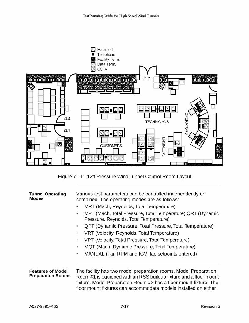
Test Planning Guide for High Speed Wind Tunnels
A027-9391-XB2 7-17 Revision 5
Figure 7-11: 12ft Pressure Wind Tunnel Control Room Layout
Tunnel Operating Modes
Various test parameters can be controlled independently or combined. The operating modes are as follows:• MRT (Mach, Reynolds, Total Temperature)• MPT (Mach, Total Pressure, Total Temperature) QRT (Dynamic
Pressure, Reynolds, Total Temperature)• QPT (Dynamic Pressure, Total Pressure, Total Temperature)• VRT (Velocity, Reynolds, Total Temperature)• VPT (Velocity, Total Pressure, Total Temperature)• MQT (Mach, Dynamic Pressure, Total Temperature)• MANUAL (Fan RPM and IGV flap setpoints entered)
Features of Model Preparation Rooms
The facility has two model preparation rooms. Model Preparation Room #1 is equipped with an RSS buildup fixture and a floor mount fixture. Model Preparation Room #2 has a floor mount fixture. The floor mount fixtures can accommodate models installed on either
CUSTOMERS
OP
ER
ATO
RS
TECHNICIANS
MacintoshTelephoneFacility Term.Data Term.CCTV
EN
GIN
EE
RS
213
214
212
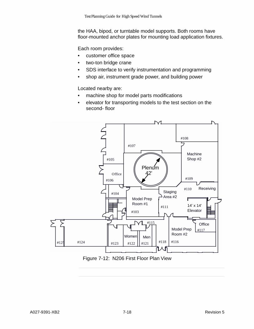
Test Planning Guide for High Speed Wind Tunnels
A027-9391-XB2 7-18 Revision 5
the HAA, bipod, or turntable model supports. Both rooms have floor-mounted anchor plates for mounting load application fixtures.
Each room provides:• customer office space• two-ton bridge crane• SDS interface to verify instrumentation and programming• shop air, instrument grade power, and building power
Located nearby are:• machine shop for model parts modifications• elevator for transporting models to the test section on the
second- floor
Figure 7-12: N206 First Floor Plan View
#105
#107
#106
#104
#103
#118#121
#108
#109
#110
#111
#117
#115
#116#122#123#124#125
MachineShop #2
Model PrepRoom #1
Model PrepRoom #2
Office
Office
ReceivingStagingArea #2
Women Men
14' x 14'Elevator
42'Plenum

Test Planning Guide for High Speed Wind Tunnels
A027-9391-XB2 A-1 Revision 5
Appendix A Checking Taper Fits
Taper Fits
Wind tunnel models at Ames are supported by stings or wall-mounted assemblies that have mated, tapered joints. The contact between the male and female tapers must be accurate to assume full and even transfer of loads.
Customers who make tapers to mate with Ames’ equipment can obtain the appropriate male or female taper gauge by contacting the Test Manager. Customers are responsible for fitting their taper to the gauge, and all customer-supplied taper joints, with not less than 80% contact area that is evenly distributed on the contacting surfaces.
The approved technique is to use fluorescent penetrant. Other techniques may be used, but please first submit procedures to and receive approval from the Test Manager.
Taper Fit Procedures
The procedures for performing taper fits are found in the Standard Operating Procedures for Sting Assembly and Storage Facility.
Customers may request a copy of these procedures from the Test Manager.

Test Planning Guide for High Speed Wind Tunnels
A027-9391-XB2 B-1 Revision 5
Appendix B List of Sting Hardware in Ames Inventory
Description This appendix contains a list of model support (sting) hardware that Ames has available as of October, 1994.
Table Legend The sting hardware table legend is shown below.
Examples Hardware items in the following examples are identified by “sting room” number (SR #). The following examples illustrate properties for two types of hardware.
Example One —
SR # Sting Assembly and Storage Facility Inventory Number
FTS Front (upstream) Taper Size (inches)
FG Front Taper Gender (M=male, F=female)
RTS Rear (downstream) Taper Size (inches)
RG Rear Taper Gender (M=male, F=female)
Bα Bend Angle (degrees)
MB Minimum Bore Diameter Through Sting (inches)
L1 Axis 1 Length (inches) Rear Taper Not Included
L2 Axis 2 Length (inches)
VO Vertical Offset (inches)
W Weight (pounds)
RC Rockwell C Hardness
D2
L2
D1
Bend Angle(°)L1
Forward
SR - 13
Minimum bore

Test Planning Guide for High Speed Wind Tunnels
A027-9391-XB2 B-2 Revision 5
Adapter SR-13
Example Two—
Primary Adapter SR-13
SR # FTS FG Front Taper Type
RTS RG Rear Taper Type
B
α
MB L1 L2 VO W Rc
13 4.5 F Cornell 4.5" 4.5 M Ames 4.5 Threaded, Push-on/off
10 1.5 1.364
6.78
0 50
45
SR - 42
Primary Adapter SR-42
SR # FTS FG Front Taper Type
RTS RG Rear Taper Type
B
α
MB L1 L2 VO W Rc
42 4.5 F Ames 4.5" Threaded
8.3 F Ames 8.3" Standard
10 4 14.69
10.613
0 405
26

Test Planning Guide for High Speed Wind Tunnels
A027-9391-XB2 B-3 Revision 5
Sting Hardware Table
The table is divided into the following categories:
Adapters Extensions
Extension/Adapters Pivot Arms
Primary Adapters Primary Adapter/Stings
Pylon Fittings Roll Mechanism/Extensions
Stings Sting/Adapters
Turnbuckle Arm
Table B-1: Adapters
SR # FTS FG Front Taper Type
RTS RG Rear Taper Type
B
α
MB L1 L2 VO W RC
1 2.75 F ? 4.5 M Ames 4.5 Threaded, Push-on/off
0 1.25
7.38
0 1.25
63 45
2 4.0 M 4.0 M 5 1.5 0 0 0 40 44
3 4.5 M Ames 4.5" Push-on/off
4.5 M Ames 4.5" Push-on/off
15 1.75
0 0 0 55 43
5 3.25 F Task 4.0 Mk II, gauge# 300400
3.25 M Task 4.0 Mk II, gauge# 300400
5 1.25
30.3
-20.2
0 52 45
6 3.0 F Sleeve 4.5 M Ames 4.5" Threaded
0 1.5 0 0 0 20 46
8 1.44 F Task 2.0 gauge# 300300(300231)
3.25 M Task 4.0 Mk II, gauge# 300400
0 1 10.75
6 0 25 33
11 4.5 F Cornell 4.5" 4.5 M Ames 4.5 Threaded, Push-on/off
0 1.5 5.59
0 0 50 45
12 4.5 F Cornell 4.5" 4.5 M Ames 4.5 Threaded, Push-on/off
0 1.25
6.38
5.25
0 65 44
13 4.5 F Cornell 4.5" 4.5 M Ames 4.5 Threaded, Push-on/off
10 1.5 1.364
6.78
0 50 45
18 4.5 M Ames 4.5" Push-on/off
4.5 M Ames 4.5" Push-on/off
5 1.75
0 0 0 55 40

Test Planning Guide for High Speed Wind Tunnels
A027-9391-XB2 B-4 Revision 5
19 3.0 M Langley 4.5 M Ames 4.5" Push-on/off
0 1 18.5
0 0 55 35
20 3.25L
F Task 4.0 Mk IV, gauge# 4626
4.5 F Ames 4.5" Push-on/off
0 1.75
17.75
0 0 50 44
35 F Press Fit Bolt On
4.5 M Ames 4.5" Push-on/off
0 0 12.38
47.25
33.5
510
38
94 2.0L F Task 2.5 MkXX, gauge#3340, 2.5L
3.25 M Task 4.0 Mk II, gauge# 300400
25 1.38
0.25
21 0 40 43
96 1.44 F Task 2.0 gauge# 300300(300231)
2.0 M Task 2.5 Mk III, gauge# 300373
49 0 7.32
13.81
0 25 41
106 3.25 F Task 4.0 Mk II, gauge# 300400
3.25 M Task 4.0 Mk II, gauge# 300400
13 0.68
7 0 0 30 43
126 2.875
F Ames 2.875" Standard(6X6)
Bolt On 0 0 9 0 0 30 -11
127 4.5 F Ames 4.5" Push-on/off
2.875
M Ames 2.875" Standard(6X6)
0 0.75
9 0 0 35 43
140 2.0 F Task 2.5 Mk III, gauge# 300373
Bolt On 0 1.8 3.88
0 0 7 38
141 1.05 F Task 1.5 Mk II, gauge# 300366
Bolt On 0 0.9 2.19
0 0 3 34
143 2.0 F Task 2.5 Mk III, gauge# 300373
1.44 M Task 2.0 gauge# 300300(300231)
0 0.44
3.25
0 0 3 37
145 2.0 F Task 2.5 Mk III, gauge# 300373
2.0L M Task 2.5 MkXX, gauge#3340, 2.5L
0 0.63
4.25
0 0 5 39
Table B-1: Adapters
SR # FTS FG Front Taper Type
RTS RG Rear Taper Type
B
α
MB L1 L2 VO W RC

Test Planning Guide for High Speed Wind Tunnels
A027-9391-XB2 B-5 Revision 5
146 2.0 F Task 2.5 Mk III, gauge# 300373
2.0L M Task 2.5 MkXX, gauge#3340, 2.5L
5 0.75
4 0 0 7 50
149 1.44 F Task 2.0 gauge# 300300(300231)
2.0 M Task 2.5 Mk III, gauge# 300373
55 0.5 0 0 0 12 36
150 1.44 F Task 2.0 gauge# 300300(300231)
1.125
F Fork 0 0.75
3.75
8.25
0 5 37
165.1 3.25L
F Task 4.0 Mk IV, gauge# 4626
Bolt On 0 0 15.25
0 0 40 47
165.2 2.0 F Task 2.5 Mk III, gauge# 300373
Bolt On 0 0 11.25
0 0 10 43
165.3 Bolt On Bolt On 0 0 7.63
2.75
1 5 31
169.1 5.50 F ? 4.875
F ? 0 0 6 0 7 80 36
169.2 4.875
M ? 4.5 M Ames 4.5 Threaded, Push-on/off
0 0 0 0 0 55 41
170 4.5 F Ames 4.5" Push-on/off
0 4.1 9.75
0 0 50 47
171 5.0 F ? 0 0 24 0 0 125
31
174.9 1.00 F Pinned Bolt On 0 0 23.3
0 0 325
-12
183 2.875
F Ames 2.875" Standard(6X6)
Bolt On 0 1.75
8.25
0 0 30 37
184 1.44 F Task 2.0 gauge# 300300(300231)
2.0 M Task 2.5 Mk III, gauge# 300373
0 0.63
3.88
0 0 10 42
Table B-1: Adapters
SR # FTS FG Front Taper Type
RTS RG Rear Taper Type
Bα MB L1 L2 VO W RC
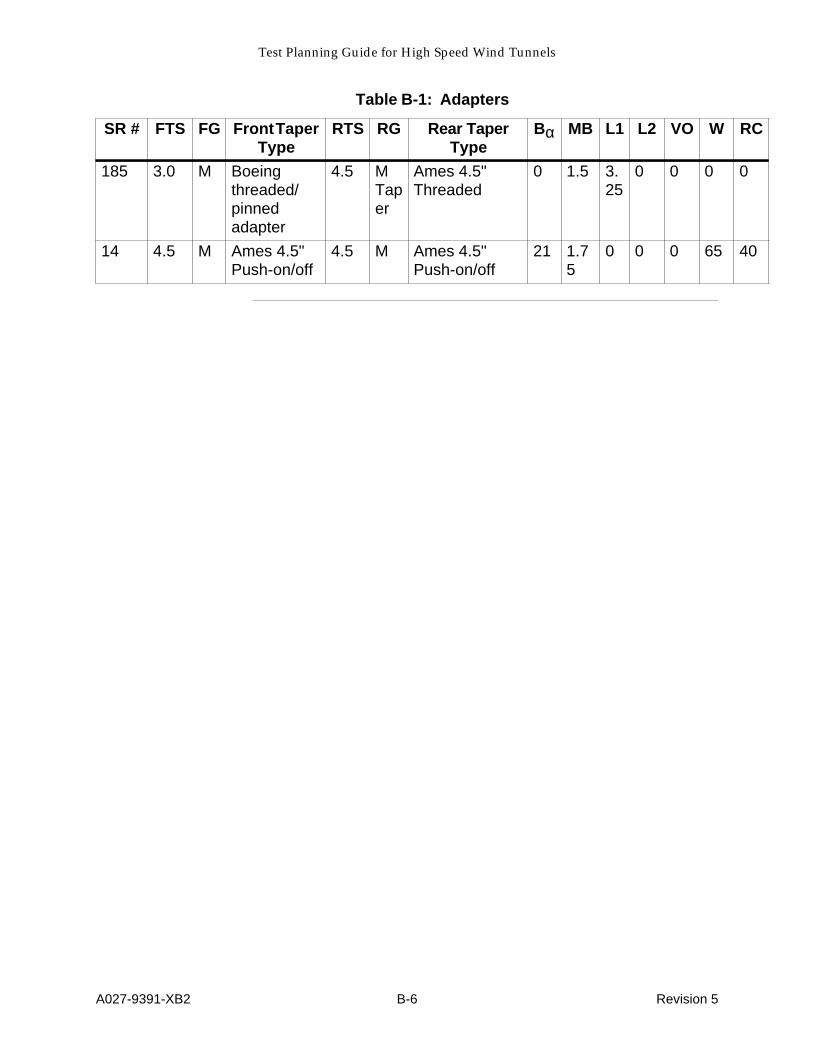
Test Planning Guide for High Speed Wind Tunnels
A027-9391-XB2 B-6 Revision 5
185 3.0 M Boeing threaded/pinned adapter
4.5 M Taper
Ames 4.5" Threaded
0 1.5 3.25
0 0 0 0
14 4.5 M Ames 4.5" Push-on/off
4.5 M Ames 4.5" Push-on/off
21 1.75
0 0 0 65 40
Table B-1: Adapters
SR # FTS FG Front Taper Type
RTS RG Rear Taper Type
Bα MB L1 L2 VO W RC

Test Planning Guide for High Speed Wind Tunnels
A027-9391-XB2 B-7 Revision 5
Blank Page

Test Planning Guide for High Speed Wind Tunnels
A027-9391-XB2 B-8 Revision 5
Table B-2: Extensions
SR # FTS FG Front Taper Type
RTS RG Rear Taper Type
B
α
MB L1 L2 VO W RC
27 4.5 F Ames 4.5" Push-on/off
4.5 M Ames 4.5 Threaded, Push-on/off
0 2 30 10 0 275
39
28 4.5 F Ames 4.5" Push-on/off
4.5 M Ames 4.5 Threaded, Push-on/off
0 1.5 27.3
10 0 270
36
29 4.5 F Ames 4.5" Push-on/off
4.5 M Ames 4.5 Threaded, Push-on/off
0 2 30 10 0 280
36
30 4.5 F Ames 4.5" Push-on/off
4.5 M Ames 4.5 Threaded, Push-on/off
0 2 30 10 0 280
44
34 4.5 F Ames 4.5" Push-on/off
4.5 M Ames 4.5" Threaded
0 1.5 22.5
10 0 160
46
64 4.5 F Ames 4.5" Push-on/off
4.5 M Ames 4.5 Threaded, Push-on/off
0 2 50 9.75
0 470
46
75 2.875
F Ames 2.875" Standard(6X6)
2.875
M Ames 2.875" Standard(6X6)
0 0.75
30 0 0 100
30
159 8.3 M Ames 8.3" Standard
8.3 F Ames 8.3" Ringless
0 2 40.69
0 0 1640
34
163 8.3 M Ames 8.3" Standard
8.3 F Ames 8.3" Standard
0 2 20 0 0 730
41
167 2.875
F Ames 2.875" Standard(6X6)
2.875
M Ames 2.875" Standard(6X6)
0 1 64.7
0 0 210
-5
168 2.875
F Ames 2.875" Standard(6X6)
2.875
M Ames 2.875" Standard(6X6)
0 1 13.7
0 0 45 26
182 2.875
F Ames 2.875" Standard(6X6)
2.875
M Ames 2.875" Standard(6X6)
0 1 15.6
0 0 50 26

Test Planning Guide for High Speed Wind Tunnels
A027-9391-XB2 B-9 Revision 5
Table B-3: Extension/Adapter
SR # FTS FG Front Taper Type
RTS RG Rear Taper Type
B
α
MB L1 L2 VO W RC
4 2.875
F Ames 2.875" Standard(6X6)
4.5 M Ames 4.5" Threaded
0 2 14.57
0 0 70 35
7 2.0 F Task 2.5 Mk III, gauge# 300373
4.5 M Ames 4.5" Threaded
0 1.5 15.38
0 0 75 42
9 4.0 F Co-op gage H580
3.25L
F 0 1.53
22.18
0 0 85 41
15 2.875
F Ames 2.875" Standard(6X6)
4.5 M Ames 4.5 Threaded, Push-on/off
0 2 15.57
0 0 75 33
22 2.5 M Langley 4.5 M Ames 4.5" Threaded
0 0 23.5
0 0 170
39
23 2.875
F Ames 2.875" Standard(6X6)
4.5 M Ames 4.5 Threaded, Push-on/off
0 1.5 30.37
0 0 130
37
24 3.25 M Langley 4.5 F Ames 4.5" Threaded
0 1.12
16.81
0 0 190
40
33 2.875
F Ames 2.875" Standard(6X6)
4.5 M Ames 4.5 Threaded, Push-on/off
0 2 30 0 0 130
33
63 2.875
F Ames 2.875" Standard(6X6)
4.5 M Ames 4.5 Threaded, Push-on/off
0 1.75
47.08
0 0 310
38
74 4.0 M Taper
Co-op gage H580
4.5 M Ames 4.5 Threaded, Push-on/off
12 1.5 16.87
0 0 130
43

Test Planning Guide for High Speed Wind Tunnels
A027-9391-XB2 B-10 Revision 5
80 2.875
F Ames 2.875" Standard(6X6)
4.5 M Ames 4.5" Threaded
0 1 28.38
0 0 110
35
153 1.05 F Task 1.5 Mk II, gauge# 300366
2.875
M Ames 2.875" Standard(6X6)
0 0.38
55.5
79 0 125
32
154 1.875
F Sleeve 2.875
M Ames 2.875" Standard(6X6)
45 0 0 0 0 80 31
155 4.0 F Specific to the W1148 Parts Series
4.5 M Ames 4.5 Threaded, Push-on/off
0 1.5 27.39
0 0 145
42
158 2.875
F Ames 2.875" Standard(6X6)
4.5 M Ames 4.5" Threaded
0 2 14.38
0 0 70 34
44 4.5 F Ames 4.5" Push-on/off
8.3 F Ames 8.3" Standard
0 1.75
46.38
0 0 570
31
Table B-3: Extension/Adapter
SR # FTS FG Front Taper Type
RTS RG Rear Taper Type
B
α
MB L1 L2 VO W RC
Table B-4: Pivot Arms
SR # FTS FG Front Taper Type
RTS RG Rear Taper Type
B
α
MB L1 L2 VO W RC
164.3 4.5 F Ames 4.5 Threaded, Push-on/off
1.5 F Pinned 0 4.1 8.25
9 0 60 36
174.1 Pinned Bolt On 0 0 9.25
7.75
0 40 44
174.2 Bolt On Pivot Arm Sting 0 0 22.75
0 0 45 44
174.3 Bolt On Pivot Arm Sting 0 0 22.75
0 0 55 41

Test Planning Guide for High Speed Wind Tunnels
A027-9391-XB2 B-11 Revision 5
174.4 2.0 F Task 2.5 Mk III, gauge# 300373
Pivot Arm Sting 0 0 27.5
0 0 45 34
174.7 2.0 F Task 2.5 Mk III, gauge# 300373
Pivot Arm Sting 0 0 44.5
0 0 75 35
174.8 2.875
F Ames 2.875" Standard(6X6)
Pivot Arm Sting 0 0 0 0 0 45 39
Table B-4: Pivot Arms
SR # FTS FG Front Taper Type
RTS RG Rear Taper Type
B
α
MB L1 L2 VO W RC

Test Planning Guide for High Speed Wind Tunnels
A027-9391-XB2 B-12 Revision 5
Table B-5: Primary Adapters
SR # FTS FG Front Taper Type
RTS RG Rear Taper Type
B
α
MB L1 L2 VO W RC
36 4.5 F Ames 4.5" Threaded
8.3 F Ames 8.3" Standard
0 4.5 25.38
0 0 370
26
37 4.5 F Ames 4.5" Threaded
8.3 F Ames 8.3" Standard
10 4 14.69
10.61
0 405
23
38 4.5 F Ames 4.5" Threaded
8.3 F Ames 8.3" Standard
0 4.38
25.38
0 0 360
35
40 4.5 F Ames 4.5" Threaded
8.3 F Ames 8.3" Standard
20 4.1 15.81
10.61
0 400
32
41 4.5 F Ames 4.5" Threaded
8.3 F Ames 8.3" Standard
12.5
4 14.69
9.90
0 405
32
42 4.5 F Ames 4.5" Threaded
8.3 F Ames 8.3" Standard
10 4 14.69
10.613
0 405
26
43 4.5 F Ames 4.5" Threaded
8.3 F Ames 8.3" Standard
0 4.38
25.38
0 0 370
27
45 6.9 F Grumman 6.9"
8.3 F Ames 8.3" Standard
5 6 26 0 0 360
11
46 4.5 F Ames 4.5" Threaded
8.3 F Ames 8.3" Standard
5 4 14.69
10 0 375
38
47 4.5 F Ames 4.5" Threaded
8.3 F Ames 8.3" Standard
0 4 25.38
0 0 375
35
48 4.5 F Ames 4.5" Threaded
8.3 F Ames 8.3" Standard
0 4.1 25.38
0 0 380
28
49 Bolt-On 8.3 F Ames 8.3" Standard
0 2 47.73
26.22
0 755
47
161 Northrop Model 403
8.3 F Ames 8.3" Standard
0 4 55.21
0 0 1880
33

Test Planning Guide for High Speed Wind Tunnels
A027-9391-XB2 B-13 Revision 5
162 6.0 M Langley 8.3 F Ames 8.3" Standard
0 0 38.5
0 0 870
44
164 F Fork 8.3 F Ames 8.3" Standard
0 2 38 0 0 410
24
175 9.2 M Clamp 8.3 F Ames 8.3" Standard
0 7.2 17.88
0 0 295
34
59 2.875
F Ames 2.875" Standard(6X6)
8.3 F Ames 8.3" Standard
0 1.5 59 0 0 900
29
Table B-6: Primary Adapter/Stings
SR # FTS FG Front Taper Type
RTS RG Rear Taper Type
B
α
MB L1 L2 VO W RC
50 3.25L
F Task 4.0 Mk IV, gauge# 4626
8.3 F Ames 8.3" Standard
0 2 111.6
0 0 885
27
51 3.25 F Task 4.0 Mk II, gauge# 300400
8.3 F Ames 8.3" Standard
0 2 115.6
0 0 890
33
52 3.25L
F Task Mk IVA 4.0 Bal
8.3 F 0 2 89.5
0 10 905
33
53 4.0 F Task 4.0 Mk IV, gauge# 4626
8.3 F Ames 8.3" Standard
12 2 48.8
67.519
0 0 0
57 4.5 F Ames 4.5" Push-on/off
8.3 F Ames 8.3" Standard
0 1.75
66.38
0 0 665
44
Table B-5: Primary Adapters
SR # FTS FG Front Taper Type
RTS RG Rear Taper Type
B
α
MB L1 L2 VO W RC

Test Planning Guide for High Speed Wind Tunnels
A027-9391-XB2 B-14 Revision 5
Table B-7: Pylon Fittings
SR # FTS FG Front Taper Type
RTS RG Rear Taper Type
B
α
MB L1 L2 VO W RC
164.1 Pinned Bolt On 0 0 8.25
0 0 70 12
164.2 Pinned Bolt On 0 0 11.38
0 0 70 34
Table B-8: Roll Mechanism/Extensions
SR # FTS FG Front Taper Type
RTS RG Rear Taper Type
B
α
MB L1 L2 VO W RC
21 1.625
Square
Unknown 2.875
M Ames 2.875" Standard(6X6)
0 0 34 0 0 210
21
188 8.3 M Ames 8.3" Standard
8.3 F Ames 8.3" Standard
0 0 40 0 0 1380
0
189 8.3 M Ames 8.3" Standard
8.3 F Ames 8.3" Standard
0 0 40 0 0 1410
0
Table B-9: Stings
SR # FTS FG Front Taper Type
RTS RG Rear Taper Type
B
α
MB L1 L2 VO W RC
25 2.5 F Sliding fit w/D111-2
4.5 M Taper
Ames 4.5" Threaded
13 2 9.88
19.25
0 85 26
26 3.25L
F Task 4.0 Mk IV, gauge# 4626
4.5 M Ames 4.5 Threaded, Push-on/off
15 1.38
0 30.38
0 130
43
31 1.25 F Fork 4.5 M Ames 4.5 Threaded, Push-on/off
0 1 35.75
0 0 270
45
54 2.5 M Langley 4.5 M Ames 4.5 Threaded, Push-on/off
0 1.5 69.75
0 0 365
43
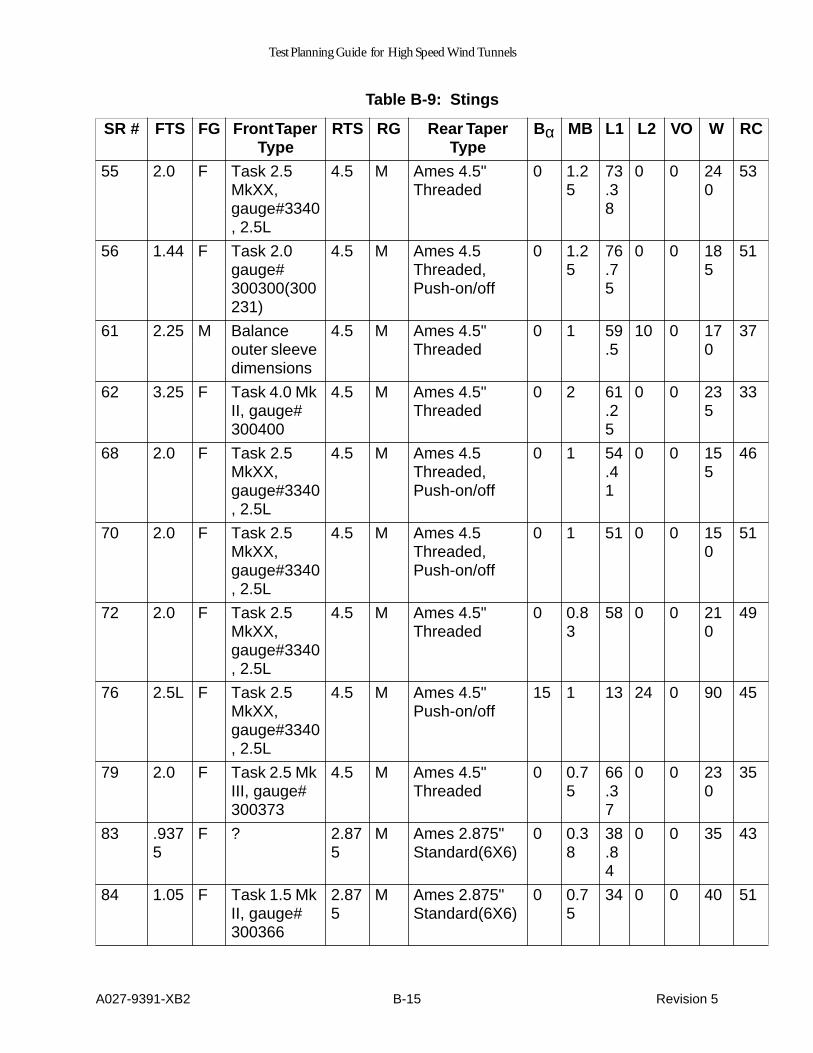
Test Planning Guide for High Speed Wind Tunnels
A027-9391-XB2 B-15 Revision 5
55 2.0 F Task 2.5 MkXX, gauge#3340, 2.5L
4.5 M Ames 4.5" Threaded
0 1.25
73.38
0 0 240
53
56 1.44 F Task 2.0 gauge# 300300(300231)
4.5 M Ames 4.5 Threaded, Push-on/off
0 1.25
76.75
0 0 185
51
61 2.25 M Balance outer sleeve dimensions
4.5 M Ames 4.5" Threaded
0 1 59.5
10 0 170
37
62 3.25 F Task 4.0 Mk II, gauge# 300400
4.5 M Ames 4.5" Threaded
0 2 61.25
0 0 235
33
68 2.0 F Task 2.5 MkXX, gauge#3340, 2.5L
4.5 M Ames 4.5 Threaded, Push-on/off
0 1 54.41
0 0 155
46
70 2.0 F Task 2.5 MkXX, gauge#3340, 2.5L
4.5 M Ames 4.5 Threaded, Push-on/off
0 1 51 0 0 150
51
72 2.0 F Task 2.5 MkXX, gauge#3340, 2.5L
4.5 M Ames 4.5" Threaded
0 0.83
58 0 0 210
49
76 2.5L F Task 2.5 MkXX, gauge#3340, 2.5L
4.5 M Ames 4.5" Push-on/off
15 1 13 24 0 90 45
79 2.0 F Task 2.5 Mk III, gauge# 300373
4.5 M Ames 4.5" Threaded
0 0.75
66.37
0 0 230
35
83 .9375
F ? 2.875
M Ames 2.875" Standard(6X6)
0 0.38
38.84
0 0 35 43
84 1.05 F Task 1.5 Mk II, gauge# 300366
2.875
M Ames 2.875" Standard(6X6)
0 0.75
34 0 0 40 51
Table B-9: Stings
SR # FTS FG Front Taper Type
RTS RG Rear Taper Type
B
α
MB L1 L2 VO W RC

Test Planning Guide for High Speed Wind Tunnels
A027-9391-XB2 B-16 Revision 5
85 .75 F Task 1.0 MkVI & XIV, gauge#6674
2.875
M Ames 2.875" Standard(6X6)
0 1 40.75
0 0 30 53
86 1.44 F Task 2.0 gauge# 300300(300231)
2.875
M Ames 2.875" Standard(6X6)
0 0.781
32.59
0 0 40 35
87 1.44 F Task 2.0 gauge# 300300(300231)
2.875
M Ames 2.875" Standard(6X6)
0 1 38.9
0 0 40 26
88 1.44 F ? 2.875
M Ames 2.875" Standard(6X6)
0 0.75
35.5
0 0 50 36
89 1.05 F 2.875
M Ames 2.875" Standard(6X6)
0 0.75
39.38
0 0 40 44
90 2.0 F Task 2.5 Mk III, gauge# 300373
2.875
M Ames 2.875" Standard(6X6)
0 0.79
17.88
0 0 30 35
91 2.0 F Task 2.5 Mk III, gauge# 300373
2.875
M Ames 2.875" Standard(6X6)
0 0.781
17.75
0 0 30 33
92 1.5 M Balance outer sleeve dimensions
2.875
M Ames 2.875" Standard(6X6)
0 1.25
23.25
0 0 20 40
93 .75 F Task 1.0 MkVI & XIV, gauge#6674
2.875
M Ames 2.875" Standard(6X6)
0 1 23.13
0 0 20 44
97.2 1.75 F Fork 2.0 M Pivot Arm Sting 0 0.75
24 1 0 80 36
97.3 1.05 F Task 1.5 Mk II, gauge# 300366
1.75 M Pivot Arm Sting 0 0.75
15.5
1 0 10 34
101 1.30 F Task 1.75 Mk I, gauge# 10191
2.875
M Ames 2.875" Standard(6X6)
0 0.75
12.5
0 0 20 32
Table B-9: Stings
SR # FTS FG Front Taper Type
RTS RG Rear Taper Type
B
α
MB L1 L2 VO W RC

Test Planning Guide for High Speed Wind Tunnels
A027-9391-XB2 B-17 Revision 5
107 2.0 F 2.875
M Ames 2.875" Standard(6X6)
0 1 37.63
0 0 45 44
108 2.0 F Task 2.5 Mk III, gauge# 300373
2.875
M Ames 2.875" Standard(6X6)
5 0.78
37.69
0 0 70 28
109 2.0 F Task 2.5 Mk III, gauge# 300373
2.875
M Ames 2.875" Standard(6X6)
0 0.78
37.69
0 0 55 19
110 1.44 F Task 2.0 gauge# 300300(300231)
2.875
M Ames 2.875" Standard(6X6)
0 0.75
33 0 0 45 54
111 2.0 F Task 2.5 Mk III, gauge# 300373
2.875
M Ames 2.875" Standard(6X6)
5 0.78
33.25
0 0 0 20
112 2.0 F Task 2.5 Mk III, gauge# 300373
2.875
M Ames 2.875" Standard(6X6)
0 1 37.69
0 0 60 29
113 2.0 F Task 2.5 Mk III, gauge# 300373
3.25 M Task 4.0 Mk II, gauge# 300400
0 0.75
21 0 0 60 44
114 1.44 F Task 2.0 gauge# 300300(300231)
2.875
M Ames 2.875" Standard(6X6)
15 1 14.75
13 0 55 32
115 1.05 F Task 1.5 Mk II, gauge# 300366
2.875
M Ames 2.875" Standard(6X6)
0 0 22.5
0 8 40 43
116 ? 2.875
M Ames 2.875" Standard(6X6)
0 0 23.5
0 0 55 11
117 2.0 F Task 2.5 Mk III, gauge# 300373
3.25 M Task 4.0 Mk II, gauge# 300400
36 1.38
0.65
17.5
0 35 44
118 1.44 F Task 2.0 gauge# 300300(300231)
2.875
M Ames 2.875" Standard(6X6)
0 0.78
32.59
0 0 40 33
Table B-9: Stings
SR # FTS FG Front Taper Type
RTS RG Rear Taper Type
B
α
MB L1 L2 VO W RC

Test Planning Guide for High Speed Wind Tunnels
A027-9391-XB2 B-18 Revision 5
119 1.44 F Task 2.0 gauge# 300300(300231)
2.875
M Ames 2.875" Standard(6X6)
4 0.75
13.1
3.2 0 20 38
123 .613 F 1.44 M Task 2.0 gauge# 300300(300231)
0 0.38
0 0 0 5 40
124 1.05 F Task 1.5 Mk II, gauge# 300366
2.0 M Task 2.5 Mk III, gauge# 300373
0 0.38
16.63
0 0 15 40
125 2.0 F Task 2.0 gauge# 300300(300231)
2 LAND SLEEVE
0 0 0 0 0 15 32
128 2.0 F Task 2.5 Mk III, gauge# 300373
2.875
M Ames 2.875" Standard(6X6)
0 0.75
32.63
0 0 60 35
129 1.05 F Task 1.5 Mk II, gauge# 300366
2.875
M Ames 2.875" Standard(6X6)
0 0.78
37.69
0 0 40 26
130 1.44 F Task 2.0 gauge# 300300(300231)
2.875
M Ames 2.875" Standard(6X6)
0 0.78
36.88
0 0 45 35
131 1.05 F Task 1.5 Mk II, gauge# 300366
2.875
M Ames 2.875" Standard(6X6)
0 0.75
37.75
0 0 40 37
132 1.44 F Task 2.0 gauge# 300300(300231)
2.875
M Ames 2.875" Standard(6X6)
0 0.78
32.59
0 0 30 37
133 .938 F ? 2.875
M Ames 2.875" Standard(6X6)
0 0.75
0 0 0 35 41
134 1.44 F Task 2.0 gauge# 300300(300231)
2.875
M Ames 2.875" Standard(6X6)
0 0.75
32 0 10 65 38
Table B-9: Stings
SR # FTS FG Front Taper Type
RTS RG Rear Taper Type
B
α
MB L1 L2 VO W RC

Test Planning Guide for High Speed Wind Tunnels
A027-9391-XB2 B-19 Revision 5
135 1.05 F Task 1.5 Mk II, gauge# 300366
2.875
M Ames 2.875" Standard(6X6)
0 0.75
37.75
0 0 30 41
136 1.05 F Task 1.5 Mk II, gauge# 300366
2.875
M Ames 2.875" Standard(6X6)
30 0.75
0 0 0 30 36
137 1.0 F Task 1.5 Mk II, gauge# 300366
2.875
M Ames 2.875" Standard(6X6)
0 0.75
37.75
0 0 35 40
138 1.44 F Task 2.0 gauge# 300300(300231)
2.875
M Ames 2.875" Standard(6X6)
0 0.78
32.63
0 0 40 30
139 1.05 F Task 1.5 Mk II, gauge# 300366
2.875
M Ames 2.875" Standard(6X6)
0 0.38
34.63
0 0 30 43
144 1.44 F Task 2.0 gauge# 300300(300231)
1.44 M Task 2.0 gauge# 300300(300231)
6 0.5 0 0 0 3 38
151 2.0 F Task 2.5 MkXX, gauge#3340, 2.5L
4.5 M Cornell 4.5" 0 0.75
42.78
0 0 100
46
152 1.44 F Task 2.0 gauge# 300300(300231)
4.5 M Cornell 4.5" 0 0.75
43 2.56
0 120
40
157 2.0L F Task 2.5 MkXX, gauge#3340, 2.5L
4.5 M Ames 4.5" Push-on/off
0 1 39.75
0 3 140
0
160 3.25 F Task 4.0 Mk II, gauge# 300400
4.5 M Ames 4.5 Threaded, Push-on/off
0 2 29 0 0 105
38
165 Bolt On 4.5 M Ames 4.5 Threaded, Push-on/off
0 0 98 0 0 545
43
Table B-9: Stings
SR # FTS FG Front Taper Type
RTS RG Rear Taper Type
B
α
MB L1 L2 VO W RC

Test Planning Guide for High Speed Wind Tunnels
A027-9391-XB2 B-20 Revision 5
166 3.25 F Task 4.0 Mk II, gauge# 300400
6.9 M Grumman 303 0 0 93 0 0 640
41
169 Bolt On 5.50 M ? 0 0 75 0 0 275
41
172 2.0 F Task 2.5 MkXX, gauge#3340, 2.5L
4.5 M Ames 4.5 Threaded, Push-on/off
0 1.25
66.38
0 0 255
41
173 Balance outer sleeve dimensions
Pivot Arm Sting 0 0 0 0 0 510
46
176 1.44 F Task 2.0 gauge# 300300(300231)
4.5 M Cornell 4.5" 0 0.75
44.5
2.56
0 120
46
178 3.25 F Task 4.0 Mk II, gauge# 300400
4.5 M Cornell 4.5" 0 1 40.75
0 0 165
47
181 2.0 F Task 2.5 Mk III, gauge# 300373
2.875
M Ames 2.875" Standard(6X6)
0 0.785
36 0 0 55 39
186 F Socket
0 F Socket
0 1 50.21
0 0 0 0
187 2.0 F Task 2.5 Mk III, gauge# 300373
2.875
M Ames 2.875" Standard(6X6)
0 0.78
40.41
0 0 0 0
Table B-9: Stings
SR # FTS FG Front Taper Type
RTS RG Rear Taper Type
B
α
MB L1 L2 VO W RC
Table B-10: Sting/Adapters
SR # FTS FG Front Taper Type
RTS RG Rear Taper Type
B
α
MB L1 L2 VO W RC
69 1.44 F Task 2.0 gauge# 300300(300231)
3.25 F Langley? 0 0.75
62.25
0 0 105
41

Test Planning Guide for High Speed Wind Tunnels
A027-9391-XB2 B-21 Revision 5
’
71 3.0 F ? 4.5 M Ames 4.5" Threaded
0 2 47.13
0 0 215
40
97.1 2.0 F Fork 2.875
M Ames 2.875" Standard(6X6)
0 0.75
6 1 0 30 36
174 1.375
F Pivot Arm Sting
4.5 M Ames 4.5 Threaded, Push-on/off
0 0 33 0 0 230
38
174.5 1.313
F ? Bolt On 0 0 15.63
0 0 10 33
174.6 1.375
F ? Bolt On 0 0 15 0 0 20 44
177 ? 4.5 M Cornell 4.5" 0 0 45.75
0 0 165
41
Table B-10: Sting/Adapters
SR # FTS FG Front Taper Type
RTS RG Rear Taper Type
B
α
MB L1 L2 VO W RC
Table B-11: Turnbuckle Arm
SR # FTS FG Front Taper Type
RTS RG Rear Taper Type
B
α
MB L1 L2 VO W RC
164.4 1.00 F Pinned 1.00 F Pinned 0 0 52 0 0 60 19

Test Planning Guide for High Speed Wind Tunnels
A027-9391-XB2 C-1 Revision 5
Appendix C Summary of Customer Actions and Deliverables
C.1 General Checklist
Description
The following table is a checklist of items expected from customers in the time frames shown.
Table C-1: Customer Supplied Items Checklist
Item Recommended. no. of weeks prior to
test
Test Justification Meeting 26
Initial Test Planning Meeting 12
Test Objective Document 13
Request for use of general support systems contained in Section 6.0
8
Request for use of instrumentation items contained in Appendix D.
8
Data-plotting requests 8
Drawings of model support systems and installations
6
Customer data-reduction equations 6
Customer balance if calibration required 6
Customer-supplied model support hardware (stings) 6
Stress report 6
Model assembly, installation, and change procedures
6
Model cross-sectional area distribution 4
Finalized run schedule 4
Details of Customer-furnished equipment 4
Customer-supplied constants for the data-reduction program
4
Customer-supplied calibrations 4
MSDS sheets for all Customer-supplied chemicals 4
Personnel arrival information See sec. 3
Model and support equipment 1

Test Planning Guide for High Speed Wind Tunnels
A027-9391-XB2 C-2 Revision 5
C.2 Test Request Form
Description
This form is filled out by the customer to inform the Wind Tunnel and Aerodynamics group of the services needed. A blank form is shown in Figure C-1. This form may be copied for use by a Customer. It is also available electronically on Microsoft® Word.

Test Planning Guide for High Speed Wind Tunnels
A027-9391-XB2 C-3 Revision 5
Figure C-1: Test Request Form (Sheet 1 of 3)
TEST REQUEST FORMTest Title:
Requestor Information:
Organization: Contact:
(Include name and title)
Address:Telephone: Voice: Fax:E-mail:
Sponsor Information:
Organization:
(Principle sponsor such as NASA, DoD, Air Force, Navy, Company, etc.)
Contact:
(Include name and titled
Address:Telephone: Voice: Fax:E-mail:
Other Organizations Supporting the Test:
(Secondary organizations that will be supporting the test and what that support is: staffing, money, equipment, etc. For example provide company name, number of researchers, number of test managers, and number of model technicians)
Program Affiliation:
Program Office:Airframe Systems High Speed ResearchCivil Transports Advanced Subsonic TechnologyHigh Performance Aircraft RotorcraftFundamental Concepts & Methods Space TransportationOther
Schedule
:Requested Test Section Occupancy Entry Date (M/D/Y)Estimated (Test section occupancy hours)Earliest date model can be delivered to facility (M/D/Y)Latest date for test completion (M/DN)
Facility Preference (if known)
General Description of the Test:

Test Planning Guide for High Speed Wind Tunnels
A027-9391-XB2 C-4 Revision 5
Figure C-1: Test Request Form (Sheet 2 of 3)
Specific Test Objectives:
Model/Test Hardware:
Designation: Scale:Description:Size (key dimensions such as, wing area, span, length, blockage area, weight, etc.Minimum possible scale should also be included):
Current Status: Concept definition Design Fabrication Ready for testPreviously Tested
Where tested When tested
Type of Test (Circle all that apply):
Aircraft/missile performance InletAircraft/missile stability and control 2-D AirfoilRotorcraft STOVLForced oscillation Ground EffectsFree flight AcousticPropulsionBurning propulsion system Propulsion/airframe integr. testNozzle testHGIFuels required (please list)Other test type -describe:
Model/Configuration Changes:Total number of changes
Percent - Remove and reinstall model Percent - Major model component change Percent - Control surface change
Estimate of average time required to make changes if knownRemove and reinstall model Major model component change Control surface change
Indicate time required for any changes that are significantly longer than the average.

Test Planning Guide for High Speed Wind Tunnels
A027-9391-XB2 C-5 Revision 5
Figure C-1: Test Request Form (Sheet 3 of 3)
Type of Data Required:
Force and moment No. of data points Strain gaugePressures (ESP) Approx. No. of orifices No. of data points Model DeformationDynamic No. of data points Pressure sensitive paint No. of data points Temperature sensitive paint No. of data points Acoustic No. of data points
Flow visualizationType: Surface flow Off-bodyDescribe requirement:
Other data requirements:
Classification requirements
Test Conditions:
Mach number schedule: Reynolds number scheduleDynamic Pressure(s) Angle of attack scheduleAngle of side slip schedule Nozzle pressure ratio scheduleWeight flow schedule (inlet)
Other: Include detailed test matrix as enclosure if known
Instrumentation Requirements
Facility supplied
User supplied
Special Requirements
High pressure air pressure level and mass flow rate), exhaust (vacuum level and mass flow rate), cooling (temperature, water or air with mass flow rates), heating requirements, unique systems, additional space, remote access control room, hydraulics, (pressure level and flows), steam special data reduction requirements (plotting, format, etc.), know facility modifications required to accommodate test apparatus, etc.
Request Submitted: (Date M/D/Y)

Test Planning Guide for High Speed Wind Tunnels
A027-9391-XB2 C-6 Revision 5
C.3 Initial Test Planning Meeting Guide
Description
This guide is used by both the Customer and the Test Manager to set the agenda for the Initial Test Planning meeting. An example is shown in Figure C-2.

Test Planning Guide for High Speed Wind Tunnels
A027-9391-XB2 C-7 Revision 5
Figure C-2: Initial Test Planning Meeting Guide (Sheet 1 of 2)
INITIAL TEST PLANNING MEETING GUIDE
(Address specific concerns & issues during appropriate sections)
I.OPENING (Test Manager) 1. Introduction of user representatives. 2. Introduce key Ames personnel. 3. Explain Ames' role regarding this test. (Including staffing) 4. State test date, prep room availability, 8 occupancy hours/shifts per day. 5. Restate required/updated dates for stress, program, stings, model.
II.TEST OVERVIEW&OBJECTIVES [Customer representative(s)] - Three copies of the pretest report provided one week prior to the meeting. - No questions from the field on other matters allowed! Only clarifications. 1. Test program overview and objectives.2. Ames specific objectives & requirements. (Drag, S&C, pressure/loads...) 3. Sponsoring agency/Co-op & security classifications, if any. 4. Review present run schedule. (stream, high Rn, bridging, expected loads) - What are the real alpha schedule requirements-angles or increments?
III. MODEL HARDWARE DESCRIPTION [Customer representative(s)]1. Support system:- Whose stings & adapters. (what is total length & tunnel stations)- Status/locations of pieces and tapers. (are gauges needed?, time frames)- Has aerodynamic interference been investigated?2. Model description:- Scale, blockage, & pertinent dimensions. (Include drawing if appropriate)- High pressure air & hydraulics requirements.- Control surface inputs/requirements. (Manual or remote)(Cover remote surface power/signal specs in section IV)- Level plate specifics. (Size, weight, good at phi = 0, 90, 180 deg. as app.)- Special fixtures for check loading etc.- Boundary trip kind, sizing & application pattern. How long to apply?3. Overall stress requirement satisfaction: (Receive preliminary section 5.0).- What conditions are loads based on; theoretical or previous data?- Model & sting assembly: (what parts have S.F. < 4 & 3 on ult. & yield?)- Any exposed welds that are not otherwise bolted in. (inspect. req'd)- Screw/bolt/pin certification. (unopened boxes plus lot inspections)- Hardness checks/requirements.

Test Planning Guide for High Speed Wind Tunnels
A027-9391-XB2 C-8 Revision 5
Figure C-2: Initial Test Planning Meeting Guide (Sheet 2 of 2)
- Countersinks (inspections at Ames)- Support system: Will any stings/adapters need special inspections?- Balance inner rod safety factor. (catastrophic > 3.0)- Proof loading requirements.- We need estimated sting assy deflection & lift curve slopes, & ref area.
IV. INSTRUMENTATION (Test Manager or instrument engineer)1. Balance: How was it sized? (supplier & backup)
- Calibration (by who, load range, delivery format for Ames....)- Status of internal thermocouples.- State
our realtime, BLAMS & Oscillograph monitoring capabilities.2. Angle of attack: Sources (how many, main, supplier, conditioning....)3. Pressures: PSl's or individual transducers. (who will supply, size, kind....)- Location (model or strut) (how are base & cavity read?)- Reference, monitor requirements, port assignments etc.- Tubing: Number, size, kind, supplier...4. Thermocouples. (additionals & type if applicable)5. Position indicators. (if applicable)6. Buffet gauges, accelerometers, RMS system, & other unique reqm'nts.7. Photo/video requirements.- Flow visualization requirements. (Schlieren, oil flow, sublimation, etc.)8. Cable routing, (internal or external to sting assembly) & length.
V. DATA PROCESSING (Test Manager or DPG representative)1. Equations & corrections: Test equations supplied by NASA or Customer?- Base, cavity, duct, mass flow, pressure integrations, RMS, etc....- Stream angle, wall, buoyancy, Mach table & blockage corrections.- Coeff axes, output (line printer) format-if any.- Display &/or monitoring requirements.- Sampling rates & duration. (frequency response required)2. Plotting requirements: DPS3. User computer: Kind and link type. (Decnet or TCP/IP, address)- Data flow format (CDDMS) and frequency.- Final transmittal medium and format (End of test & at 2 weeks post)
Vl.SECURITY (Test Manager or security representative)1. Classification: Computed & raw data, DGP, model, pictures, etc....2. Facility lock up, padlocks, combinations, main entrance, guards.....3. Access list, changes, escorting, data storage.4. Data cleansing requirements (test directory only, or entire disk pack)
Vll. SUMMARY & ACTION ITEMS (Test Manager)1. Review & summarize all action items and dates due.- Schedule, hardware, instrumentation, data reduction.

Test Planning Guide for High Speed Wind Tunnels
A027-9391-XB2 C-9 Revision 5
C.4 Test Requirements Document Outline
Description
This outline is used by both the Customer and the Test Manager to delineate the requirements and objectives of the Customer. An example is shown in Figure C-3.

Test Planning Guide for High Speed Wind Tunnels
A027-9391-XB2 C-10 Revision 5
Figure C-3: Test Requirements Document Outline (Sheet 1 of 2)
TEST REQUIREMENTS DOCUMENT
I TEST PROGRAM OVERVIEW a) Program objectives b) Program schedule
II TEST OBJECTIVES at AMES a) Contractor Requirements b) Drag, Stability & Control c) Pressure Information d) Run Schedule - Priorities, Procedures, Configuration Codes e) Test Support, Contacts, Addresses & Phone Numbers
III MODEL & HARDWARE DESCRIPTION a) Sting Hardware Assembly & Distortion b) Model Sizing c) Control Surfaces d) Area Distributions e) Parts/Drawings list f) Loads Sources & Estimates g) Boundary Trip Sizing, Application & Philosophy h) Model Instrumentation and tap locations
IV INSTRUMENTATION a) Balance - Description, Capacity, Calibration, Backup, pin hole b) Angle of Attack source(s) and locations c) Pressure Instrumentation, Kinds, and Port Assignments d) Thermocouples, Position pots, Strain Gauges & Others e) Flow Visualization, Photo & Video
V DATA PROCESSING a) Ames Corrections - Base, Cavity, Buoyancy, Stream, wall, etc.b) User Corrections - to be applied by Ames computing software c) Nomenclature used and Required d) Parameters - comprehensive e) Accuracies, Repeatability & Tolerances f) Computer Hookups, Data Flow Format g) Output Formatting & Plotting

Test Planning Guide for High Speed Wind Tunnels
A027-9391-XB2 C-11 Revision 5
Figure C-3: Test Requirements Document Outline (Sheet 2 of 2)
Vl SECURITY (if applicable) a) Facility - Tunnel & Prep Room b) Model, Photographs, Video c) Computed, Real-time & Raw Data
Drawings, Charts & Tables may be included in the text or as Appendices.

Test Planning Guide for High Speed Wind Tunnels
A027-9391-XB2 D-1 Revision 5
Appendix D 12ft PWT, Instrumentation, Data Acquisition, and Data Reduction
Introduction
Ames can provide sensors, instrumentation, data systems, and the necessary engineering and technician personnel for obtaining tunnel conditions, forces, pressures, temperatures, flow visualization, and model attitude data. This section describes standard sensors, instrumentation and data systems available for supporting both test preparation and testing at the 12ft PWT.
Sensors
All Ames supplied sensors must be reserved well in advance of the actual test. Customers should address their needs at the initial test planning meeting so requirements for measurements can be clearly identified.
If the available standard instrumentation resident at the facility is insufficient to meet the objectives of a specific test, the Ames Test Manager shall be notified before the initial test planning meeting of special requirements. Existing resident systems can be expanded or modified, and special instrumentation can be added.
It is important for customers to be aware that customer supplied equipment placed inside the pressure vessel (test section and plenum) of the 12ft PWT will be subjected to pressures from sub-atmosphere to six atmospheres and will be exposed to rapid changes in pressure and temperature during pressurization and depressurization of the test section.
Instrumentation Wiring, pneumatics, And Fiber Optics
A dedicated control room is located adjacent to the Wind Tunnel Test Section. The control room is linked to the various model support systems inside the test section pressure vessel area with a limited amount of test dependent instrumentation wiring, plumbing, and fiber optics terminated in patch panels in the control room and inside the pressure vessel. Even though the physical distance between the test section and the control room is relatively short, the physical path followed by the test dependent instrumentation wiring, plumbing and fiber optics is substantially longer in order to accommodate the test section rotation capability. Customer supplied signal conditioning will need to be compatible with these long line lengths.

Test Planning Guide for High Speed Wind Tunnels
A027-9391-XB2 D-2 Revision 5
Control Room
The 12ft PWT control room is equipped with a standard set of instrumentation, data acquisition, and data analysis equipment optimized for production, pitch/pause force and moment testing in conjunction with simultaneous steady state surface pressure measurements. A portion of the control room is reserved for customer supplied equipment and customer personnel to participate with the Ames supplied personnel in the conduct of the test. The control room data system is intended for acquisition, data recording, data display, and a limited amount of data analysis. The data system has no capabilities for test dependent model controls and is not suited for dynamic data acquisition needs.
The control room is equipped with a closed circuit video system for observing the test article during running. A limited amount of video and photographic recording equipment is available. Customers should address their needs at the initial test planning meeting.
The control room data system is linked to a local Wind Tunnel network not accessible from the Internet. Remote access to the data system can be made through the use of the NASA Aeronet limited access network. Access to the Internet for customer supplied computers is available in the control room. Access to the control room data system from customer supplied analysis computers is also available. However, connection of customer computers to both the Internet and the control room data system is not allowed. Control room space utilization, interfaces with the 12ft PWT standard equipment, and network interfaces required by the customer should be addressed at the initial test planning meeting. Use of the remote access capability will require special coordination to meet all security needs.
Model Preparation Sites
Two fully equipped Model preparation sites are available to customers of the 12ft PWT facility. Equipment at these sites allow complete model/balance/model support configurations to be assembled and all model based sensor, instrumentation, and control systems to be verified prior to test section occupancy. Each model preparation site has an identical data acquisition system available in the control room. The model preparation areas are equipped with wiring, plumbing, and optical interfaces which emulate the services available in the control room and test section. Each model preparation site is equipped with a customer office. Customer supplied data analysis systems and model control systems can be interfaced and tested with the model preparation site resources. Network services and restrictions are similar to those for the control room. Test dependent wiring can be

Test Planning Guide for High Speed Wind Tunnels
A027-9391-XB2 D-3 Revision 5
assembled in the model prep rooms. Prep rooms are stocked with basic parts, tools, and materials. Tasks and required resources for model buildup should be addressed at the initial test planning meeting.
D.1 Sensors Available at Ames
Force Balances
Ames has six-component multi-piece internal strain-gage balances with normal force capacities from 5 to 6,000 pounds, five-component balances for semispan testing with normal force capacities from 6,000 to 40,000 pounds, and a small number of specialty balances. Balances are listed in Table D-1, Table D-2, and Table D-3.
Requests and reservations for use of these balances must be established at the initial test planning meeting to minimize conflicts in scheduling and calibrations. Ames can also calibrate customer balances.
Table D-1: Six-Component Internal Sting Balances (Task-Able)
Gauge capacities
Balance (diameter, inches)
N1(lbs)
N2(lbs)
S1(lbs)
S2(lbs)
A(lbs)
RM(in-lbs)
T-0.75 XIIA,B 5 5 2.5 2.5 10 10
T-0.75 XVA 100 100 50 50 30 100
T-0.75 XVIIIA 100 100 50 50 60 60
T-0.75 XXA,B,C 25 25 12.5 12.5 50 25
T-0.75 XXIXA 167 167 83.3 83.3 83.3 25
T-0.75 XXIXB 167 167 83.3 83.3 25 25
T-0.75 XXXIIA,B 5 5 5 5 10 10
T-0.75 XXXIIIA 100 100 50 50 20 60
T-0.75 XXXIVA 100 100 50 50 20 60
T-0.75 XLIA 100 100 50 50 30 100
T-1.00 IVA 125 125 125 125 250 250
T-1.00 VA 200 200 200 200 200 200
T-1.00 VIA 400 400 200 200 40 100
T-1.00 XIVA,B,C 400 400 200 200 100 250
T-1.50 IIB,D 500 500 250 250 300 800

Test Planning Guide for High Speed Wind Tunnels
A027-9391-XB2 D-4 Revision 5
T-1.50 IIC,E 500 500 250 250 100 800
T-1.50 XIIA 500 500 250 250 300 800
T-1.50 XIIIA 1000 1000 500 500 2000 500
T-1.50 XIXA 400 400 50 50 250 50
T-1.50 XXVIA 1000 1000 800 800 2000 700
T-1.75 IB 2000 2000 2000 2000 3000 1000
T-2.00 IA 900 900 450 450 160 1000
T-2.00 IIIC 900 900 450 450 500 1000
T-2.00 IIIE,F 900 900 450 450 160 1000
T-2.00 IXA 900 900 450 450 500 1000
T-2.00 XIIA 1500 1500 800 800 200 2000
T-2.00 XIVA 1500 1500 800 800 300 2000
T-2.00 XXIXA,B 2100 2100 700 700 350 3800
T-2.50 IIIA,B,D 1400 1400 700 700 280 2000
T-2.50 IVA,B 1400 1400 700 700 200 2000
T.2-50 XIA 1700 1700 700 700 1000 2000
T-2.50 XIVA 3600 3600 1800 1800 4000 1600
T-2.50 XVA 2000 2000 1000 1000 800 2000
T-2.50 XVIA 2400 2400 1200 1200 1500 4000
T-2.50 XXA,B 3000 3000 1500 1500 600 4000
T-2.50 XXXIIA 3000 3000 1500 1500 250 3000
T-2.50 XXXIVA,B 3500 3500 1800 1800 400 5000
T-2.50 XLA 3500 3500 2500 2500 400 8000
T-4.00 IIA 4000 4000 2000 2000 1000 16000
T-4.00 IIB 4000 4000 2000 2000 400 10000
T-4.00 IIC 4000 4000 2000 2000 1000 16000
T-4.00 IVA 6000 6000 3000 3000 2500 16000
Table D-1: Six-Component Internal Sting Balances (Task-Able)
Gauge capacities
Balance (diameter, inches)
N1(lbs)
N2(lbs)
S1(lbs)
S2(lbs)
A(lbs)
RM(in-lbs)
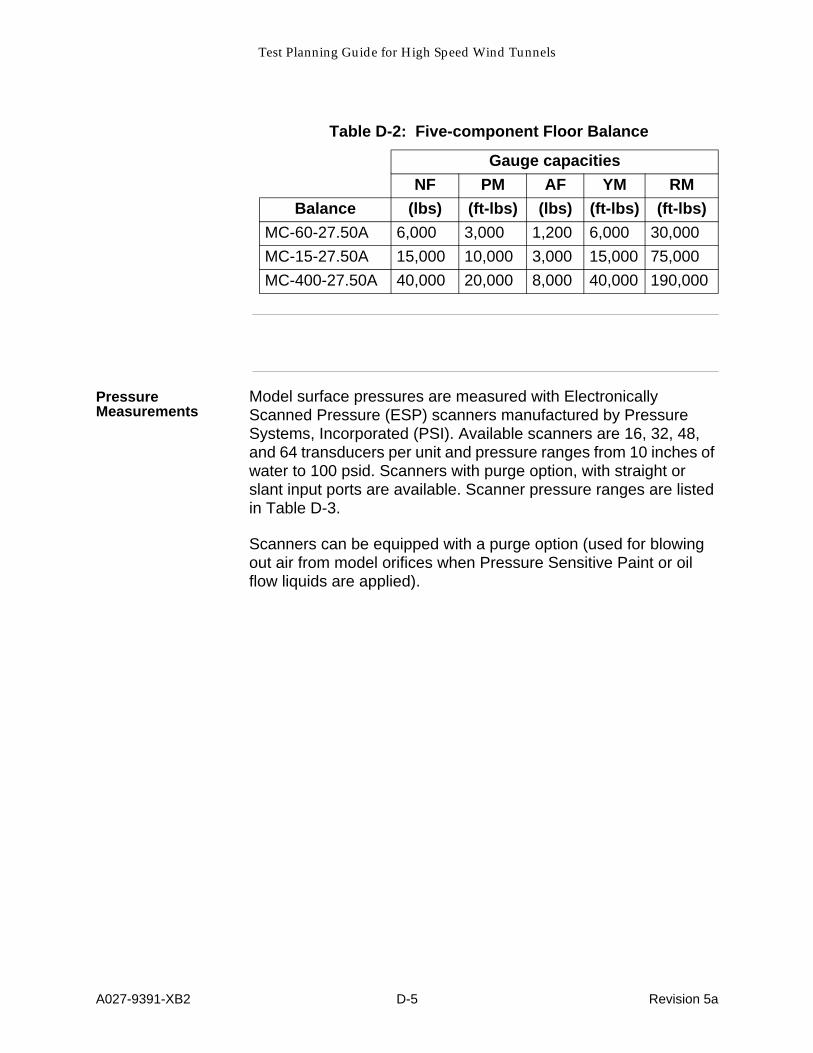
Test Planning Guide for High Speed Wind Tunnels
A027-9391-XB2 D-5 Revision 5a
Pressure Measurements
Model surface pressures are measured with Electronically Scanned Pressure (ESP) scanners manufactured by Pressure Systems, Incorporated (PSI). Available scanners are 16, 32, 48, and 64 transducers per unit and pressure ranges from 10 inches of water to 100 psid. Scanners with purge option, with straight or slant input ports are available. Scanner pressure ranges are listed in Table D-3.
Scanners can be equipped with a purge option (used for blowing out air from model orifices when Pressure Sensitive Paint or oil flow liquids are applied).
Table D-2: Five-component Floor Balance
Gauge capacities
NF PM AF YM RM
Balance (lbs) (ft-lbs) (lbs) (ft-lbs) (ft-lbs)
MC-60-27.50A 6,000 3,000 1,200 6,000 30,000
MC-15-27.50A 15,000 10,000 3,000 15,000 75,000
MC-400-27.50A 40,000 20,000 8,000 40,000 190,000

Test Planning Guide for High Speed Wind Tunnels
A027-9391-XB2 D-6 Revision 5a
As shown in Table D-4, a limited number of discrete pressure trans-ducers are available.
Tilt Sensors Ames has gravity-based tilt sensors available for angle of attack measurements. These are summarized in Table D-5 below.
Table D-3: PSI Pressure Scanner Ranges
PSI Scanners
10" H2O
20" H2O
1 psid
2.5 psid
5 psid
30 psid
50 psid
100 psid
Table D-4: Examples of discrete pressure transducers available
Type Pressure Range, psia or psid
%FS Accuracy
Output
Paroscientific Model 1000 3000, 100, 45, 23 psia. 18, 6, 3 psid.
0.01 RS232
Bourns Model ST4140 500, 1000, 1500, 2000, 3000 psia
0.25 0 to 5 vdc
Setra Model 205-2 50, 100 psia 0.10 0 to 5 vdc
Table D-5: Tilt Sensors Available
Type Angle Range, degrees
Output
Schaevitz LSCV-1556 ±14.5, ±30 ±5 vdc
Columbia SI-111311 ±15 ±5 vdc
Spectron L210R-557A w/ MUPI2 ±1, ±30 ±5 vdc

Test Planning Guide for High Speed Wind Tunnels
A027-9391-XB2 D-7 Revision 5
D.2 Institutional (Instrumentation) Cables, Pneumatics, and Fiber Optics
Description
The institutional wiring runs from the control room into termination cabinets inside the tunnel plenum. The two main sets of instrumentation lines are Turntable (TRN) and Rear Sting Support (RSS). The instrumentation lines for the TRN split to two different instrumentation cabinets that are the Bi-Pod Model Support (BMS) and the High Angle of Attack Model Support (HAA). All of the wiring available from the control room can be connected all the way to the BMS. However, only a portion of the control room to TRN wiring can be extended to the HAA model support (see Figure D-1).
Table D-7 through Table D-11 show the instrumentation capabilities of the various model support systems. Figure D-1 shows the block diagram of the locations.

Test Planning Guide for High Speed Wind Tunnels
A027-9391-XB2 D-8 Revision 5
Figure D-1
:
Block Diagram for 12ft PWT Institutional Wiring
Pressure Patch Panel
20 Pneumatic, 120 ft
20 Pneumatic, 120 ft
Control RoomPatch Panels
RSS Instrumentation Patch Panel
240 Analog, 125 ft
20 Type J Thermocouple, 125 ft
18 RG58 & 4 RG59 Coax, 230 ft
2 Triax, 125 ft
30 16-AWG, 245 ft
5 High Voltage Coax, 165 ft
24 Fiber Optic, 125 ft
240 Analog, 80 ft
20 Type J Thermocouple, 80 ft
18 RG58 & 4 RG59 Coax, 80 ft
30 16-AWG, 80 ft
20 Pneumatic, 80 ft
TRN Instrumentation Patch Panel
Control Room Patch Panels
240 Analog, 140 ft
20 Type J Thermocouple, 140 ft
26 RG58 & 4 RG59 Coax, 140 ft
51 16-AWG, 170 ft
24 Fiber Optic, 140 ft
240 Analog, 20 ft
20 Type J Thermocouple, 30 ft
26 RG58 & 4 RG59 Coax, 30 ft
51 16-AWG, 30 ft
20 Pneumatic, 30 ft
BMSPatch Panels
HAAPatch Panels
120 Analog, 80 ft
20 Type J Thermocouple, 80 ft
26 16-AWG, 80 ft
26 RG58 & 4 RG59 Coax, 80 ft
20 Pneumatic, 30 ft
(pigtails coiled in plastic bag in plenum below
where RSS was located)
Controls P:atchPanels (inside)
Controls PatchPanels (outside)
12 7-conductor Camera Strobe Cables, 165ft
Table D-7: Turntable Model Support (TRN)
Class Qty Type Mfg P/N
(length in feet)
Tunnel Patch Panel Receptacle
Mate(Receptacle P/N)
Control Room Receptacle Mate(Receptacle P/N)
Analog Signals 240(40 are used
for PSI)120 to BMS, 120 to HAA
4-cond 22 AWG shld
Belden 8723 (outside),length: 90
Belden 83349 (inside)lengths:
BMS: 70, HAA: 130
Taper pinAMP 41666
(60 position taper pin block
AMP 3-582521)
Circular connector MS3474A12-10P(MS3474L12-10S)

Test Planning Guide for High Speed Wind Tunnels
A027-9391-XB2 D-9 Revision 5
Thermocouple 20qtys can be
distributed to BMS or HAA
Type J 20 AWG T/C
shld
Belden 1000 (outside),length: 90
Belden 83950 (inside)lengths:
BMS: 70, HAA: 130
Strip wire & insert(Phoenix Contact Terminal Blocks MTKD-FE/CUNI
Type J)
(3 prong T/C jack, Omega 19TJP-1-
20-J)
Heavy Gage Wires for Mod-el Motors and
Control
51 conduc-tors (6 are
used for PSI, 21 are used
for other functions)
2-cond 16 AWG shld
Belden 9952lengths:
BMS: 200, HAA: 250
Strip wire & insertPhoenix Contact Terminal Blocks
Strip wire & insertPhoenix Contact Terminal Blocks
Pneumatic Tubing
20 (6 are used for PSI)qtys can be
distributed to BMS or HAA
1/4 inch dia nylon pneu-matic tub-
ing
Freelin-Wadelengths:
BMS: 120, HAA: 170
1/4 inch dia Swagelok Bulk-head Union SS-
400-61
1/4 inch dia Swagelok Bulk-head Union SS-
400-61
RG58 Coax 26(12 are used)qtys can be
distributed to BMS or HAA
RG58 50-ohm coax
Belden 9203lengths:
BMS: 170, HAA: 220(BNC coax con-nector, Phoenix Contact BNC-V
50)
(BNC coax con-nector, Phoenix Contact BNC-V
50)
RG59 Coax 4qtys can be
distributed to BMS or HAA
RG59 75-ohm coax
Belden 9259lengths:
BMS: 170, HAA: 220(BNC coax con-nector, Phoenix Contact BNC-V
75)
(BNC coax con-nector, Phoenix Contact BNC-V
75)
Fiber Optic 24 fibers Fiber Op-tic, 50 mi-
cron
Belden 227304length: 140
Terminates in cabi-net before BMS
and HAA cabinetsType ST
Connectors
Type ST Connectors
Table D-8: Bi-Pod Model Support (BMS) to Control Room
Class Qty Type Mfg P/N
(length in feet)
Tunnel Patch Panel Receptacle
Mate(Receptacle P/N)
Control Room Receptacle Mate(Receptacle P/N)
Analog Signals 240(40 are used
for PSI)120 to BMS120 to HAA
4-cond 22 AWG shld
Belden 8723 (outside),length: 90
Belden 83349 (inside)length: 70
Taper pinAMP 41666
(60 position taper pin block
AMP 3-582521)
Circular connec-tor MS3474A12-
10P(MS3474L12-
10S)
Thermocouple 20 Type J 20 AWG T/C shld
Belden 1000 (outside),length: 90
Belden 83950 (inside)length: 70
Strip wire & insert(Phoenix Contact Terminal Blocks MTKD-FE/CUNI
Type J)
(3 prong T/C jack, Omega 19TJP-1-
20-J)
Table D-7: Turntable Model Support (TRN)
Class Qty Type Mfg P/N
(length in feet)
Tunnel Patch Panel Receptacle
Mate(Receptacle P/N)
Control Room Receptacle Mate(Receptacle P/N)

Test Planning Guide for High Speed Wind Tunnels
A027-9391-XB2 D-10 Revision 5
Heavy Gage Wires for Model
Motors and Control
51 conductors (6 are used
for PSI, 21 are used for other
functions)
2-cond 16 AWG shld
Belden 9952length: 200
Strip wire & insertPhoenix Contact Terminal Blocks
Strip wire & insertPhoenix Contact Terminal Blocks
Pneumatic Tub-ing
20 (6 are used for PSI)
1/4 inch dia polyurethane
pneumatic tubing
Freelin-Wade 1B-025-27
length: 120
1/4 inch dia Swagelok Bulk-head Union SS-
400-61
1/4 inch dia Swagelok Bulk-head Union SS-
400-61
RG58 Coax 26(12 are used)
RG58 50-ohm coax
Belden 9203length: 170 (BNC coax con-
nector, Phoenix Contact BNC-V
50)
(BNC coax con-nector, Phoenix Contact BNC-V
50)
RG59 Coax 4 RG59 75-ohm coax
Belden 9259length: 170 (BNC coax con-
nector, Phoenix Contact BNC-V
75)
(BNC coax con-nector, Phoenix Contact BNC-V
75)
Table D-8: Bi-Pod Model Support (BMS) to Control Room
Class Qty Type Mfg P/N
(length in feet)
Tunnel Patch Panel Receptacle
Mate(Receptacle P/N)
Control Room Receptacle Mate(Receptacle P/N)
Table D-9: High Angle of Attack Model Support (HAA) to Control Room
Class Qty Type Mfg P/N
(length in feet)
Tunnel Patch Panel Receptacle
Mate(Receptacle P/N)
Control Room Receptacle Mate(Receptacle P/N)
Analog Signals 120(40 are used for
PSI)
4-cond 22 AWG shld
Belden 8723 (outside),length: 90
Belden 83349 (inside)length: 130
Taper pinAMP 41666
(60 position taper pin block
AMP 3-582521)
Circular connec-tor MS3474A12-
10P(MS3474L12-
10S)
Thermocouple 20 Type J 20 AWG T/C
shld
Belden 1000 (outside),length: 90
Belden 83950 (inside)length: 130
Strip wire & insert(Phoenix Contact Terminal Blocks MTKD-FE/CUNI
Type J)
(3 prong T/C jack, Omega 19TJP-1-
20-J)
Heavy Gage Wires for Mod-el Motors and
Control
26 conductors 2-cond 16 AWG shld
Belden 9952length: 250
Strip wire & insertPhoenix Contact Terminal Blocks
Strip wire & insertPhoenix Contact Terminal Blocks
Pneumatic Tubing
20 (6 are used for PSI)
1/4 inch dia polyurethane
pneumatic tubing
Freelin-Wade 1B-025-27
length: 170
1/4 inch dia Swagelok Bulk-head Union SS-
400-61
1/4 inch dia Swagelok Bulk-head Union SS-
400-61

Test Planning Guide for High Speed Wind Tunnels
A027-9391-XB2 D-11 Revision 5
NOTE
The RSS is not currently in place but the wiring and tubing can be used for items that are plenum-based.
RG58 Coax 26(12 are used)
RG58 50-ohm coax
Belden 9203length: 220 (BNC coax con-
nector, Phoenix Contact BNC-V
50)
(BNC coax con-nector, Phoenix Contact BNC-V
50)
RG59 Coax 4 RG59 75-ohm coax
Belden 9259length: 220 (BNC coax con-
nector, Phoenix Contact BNC-V
75)
(BNC coax con-nector, Phoenix Contact BNC-V
75)
Table D-9: High Angle of Attack Model Support (HAA) to Control Room
Class Qty Type Mfg P/N
(length in feet)
Tunnel Patch Panel Receptacle
Mate(Receptacle P/N)
Control Room Receptacle Mate(Receptacle P/N)
Table D-10: Rear Sting Support, (RSS)
Class Qty Type Mfg P/N
(length in feet)
Tunnel Patch Pan-el Receptacle
Mate(Receptacle P/N)
Control Room Receptacle Mate(Receptacle P/N)
Analog Signals 240(62 are used for
PSI and dis-crete pressure measurements)
4-cond 22 AWG shld
Belden 8723 (outside),length: 75
Belden 83349 (inside)length: 130
(pigtails coiled in plastic bag in ple-
num)
Circular connector MS3474A12-10P(MS3474L12-10S)
Thermocouple 20 (4 are used for PSI scanner temperatures)
Type J 20 AWG T/C
shld
Belden 1000 (outside),length: 75
Belden 83950 (inside)length: 130
(pigtails coiled in plastic bag in ple-
num)(3 prong T/C jack, Omega 19TJP-1-
20-J)
Heavy Gage Wires for Mod-el Motors and
Control
30 conductors (6 are used for
PSI)
2-cond 16 AWG shld
Belden 9952length: 245
Strip wire & insertPhoenix Contact Terminal Blocks
Strip wire & insertPhoenix Contact Terminal Blocks
Pneumatic Tubing
20 (6 are used for PSI)
1/4 inch dia polyurethane
pneumatic tubing
Freelin-Wade 1B-025-27
length: 195
1/4 inch dia Swagelok Bulkhead Union SS-400-61
1/4 inch dia Swagelok Bulk-head Union SS-
400-61
RG58 Coax 18 RG58 50-ohm coax
Belden 9203length: 230 (BNC coax connec-
tor)(BNC coax con-nector, Phoenix Contact BNC-V
50)

Test Planning Guide for High Speed Wind Tunnels
A027-9391-XB2 D-12 Revision 5
D.3 Data Acquisition
Functional Subsystems
Seven different Functional Subsystems are used as the front ends for data acquisition of the Standardized Data System (SDS). The Functional Subsystems are signal conditioning and digitizers controlled by a PC. The seven functional classes associated are (refer to Figure D-2):• Force balances• Steady-state surface pressures (PSI 8400)• General purpose digital input (under construction)• Temperatures
RG59 Coax 4 RG59 75-ohm coax
Belden 9259length: 230 (BNC coax connec-
tor)(BNC coax con-nector, Phoenix Contact BNC-V
75)
Double-Shield-ed Coax
2 75-ohm triax-ial double shld cable
Belden 9248length: 150
Trompeter triax connector UBJ28 w/ UPL-20-4 cable
plugs
Trompeter triax connector UBJ28 w/ UPL-20-4 cable
plugs
Fiber Optic 24 Fiber OpticV1-
Belden 227304length: 150
MA COM LCS, ST Style Multimode Fi-ber Optic Connec-
tor,P/N
3STMM125LCS
MA COM LCS, ST Style Multimode Fiber Optic Con-
nector,P/N
3STMM125LCS
High Voltage Coax
5 High Voltage Coax
Belden 8261length: 165
Kings HV Coax Connector 1705-7
Kings HV Coax Connector 1705-7(terminates at Ple-num Utilities Ter-mination Cabinet
Table D-10: Rear Sting Support, (RSS)
Class Qty Type Mfg P/N
(length in feet)
Tunnel Patch Pan-el Receptacle
Mate(Receptacle P/N)
Control Room Receptacle Mate(Receptacle P/N)
Table D-11: Camera Strobe Cables
Class Qty Type Mfg P/N
(length in feet)
Tunnel Patch Pan-el Receptacle
Mate(Receptacle P/N)
Control Room Receptacle Mate(Receptacle P/N)
Heavy Gage Cables for Camera Strobes
12 7-cond16 AWG
cable
Belden 85107length: 165
Strip wire & insertPhoenix Contact Terminal Blocks
Strip wire & insertPhoenix Contact Terminal Blocks

Test Planning Guide for High Speed Wind Tunnels
A027-9391-XB2 D-13 Revision 5
• General purpose analog inputs• Tunnel conditions and model attitude support positions• Wall Interference Correction System (WICS)
Figure D-2
:
Block Diagram for Inputs to the Standardized Data System (SDS)
Force Balances
Up to 32 channels of balance strain gages can be measured by the signal conditioning amplifiers of Functional Subsystem #1. The amplifiers provide up to 10 volts DC excitation and gains from 1 to 1024. Cutoff frequencies for filtering are 1, 10, 30, 100, 1000, 2000, 20000 Hz, and wideband. All filters are 4 pole Butterworth. All functions are computer controlled
Balance dynamics are displayed realtime on the Balance Loads Alarm Monitor System (BLAMS). The purpose of the BLAMS is to protect the delicate and expensive wind tunnel balances used at
Functional Subsystem Model Instrumentation:
Wall InterferenceCorrection System
Main Power, MUA Power, RPM, IGV PositionFacility Control System
Pressure Transmitters
Pressure Transmitters
Tunnel Total Pressure
Tunnel Static PressureModel Position Resolver Data
Model Support Resolver Display
RTD TransmittersTunnel Temperaturefrom RTD Sensors Current Loop Repeaters
Tunnel Instrumentation:
Balance
Surface Pressures SurfacePressures
Image Plane Surface Pressures
To Facility Control System
Delta Pressure Probes below Image Plane
Delta Pressure Probes on Test Section Ceiling
Balance
Digital I/O
General Purpose Analog Signals
Temperature Signals
Tunnel Conditions & Model Attitude
Signals
Sensors with Analog Output
Temperature Sensors
Sensors and/or Systems with Digital I/O SubsystemManager
UserInterfaces
Wall Pressures

Test Planning Guide Wind Tunnel Operations Division High Speed Wind Tunnels
A027-9391-XB2 D-14 Revision 5
Ames. In the 12ft PWT, it is programmed to zero the model angle-of-attack mechanism if any channel exceeds its limits for a pre-determined percentage of a variable time interval. The control room is equipped with a BLAMS unit to monitor up to eight balance channels.
General Purpose Digital Input
Under construction
Temperatures
Functional Subsystem #4 uses a VXI-based scanning A/D card for temperature signal inputs from a variety of thermocouple, RTDs, and thermistors as listed in Table D-12.
20 type J (Iron Constantan) thermocouples can be measured using the facility institutional thermocouple wiring.
An additional 47 thermocouple sensors of any standard type can be connected to a remote reference junction box inside the 12ft PWT plenum. The signals can then be routed to the control room using the institutional instrumentation wiring. These signals would then be patched to the temperature subsystem with the scanning A/D card. The reference thermistor for the scanning A/D card supporting these additional 47 thermocouples is on the reference junction box inside the plenum.
Up to 24 channels of a combination of 4-wire RTDs and 4-wire thermistors can be routed to Functional Subsystem #4 in the control room using the institutional instrumentation wiring. These signals would then be patched to the Functional Subsystem #4 chassis with the scanning A/D cards.
Table D-12: Compatible Temperature Signal Types
Thermocouple RTD, 4-wire Thermistor, 4-wire
E 100 ohm Type 85 2252 ohm
E ext 100 ohm Type 92 5Kohm
J 10Kohm

Test Planning Guide for High Speed Wind Tunnels
A027-9391-XB2 D-15 Revision 5
General Purpose Analog Inputs
The 12ft PWT analog conditioning system can accommodate 48 channels of a variety of customer-supplied analog signals such as position pots, discrete transducers, strain gages, or outputs from customer amplifiers. The analog system can provide excitation, amplification, and filtering for each channel.
The general analog amplifier racks provide up to 10 volts DC excitation and accepts inputs ±10 volt DC maximum. Discrete power supplies provide excitations up to 24 VDC.
The gain of each channel is programmable from 1 to 1024. Cutoff frequencies for filtering are 1, 10, 30, 100, 1000, 2000, 20000 Hz, and wideband. All filters are 4 pole Butterworth.
Tunnel Conditions and Model Support Positions
Tunnel Conditions—
Table D-13 shows the measurable parameters in the 12ft PWT.
* Each of these measurements have redundant sensors.
Model Attitude—
The four model support systems are:• Turn Table Model Support (TRN) for Semispan floor-mount
models.• Bi-pod Model Support (BMS) in lift, yaw, and pitch.• High Angle of Attack Model Support (HAA) in roll, pitch, and
yaw.• Rear Sting Support (RSS), not currently installed.
Table D-13: Measured Tunnel Parameters
Parameter
Total Pressure*
Total minus Static Pressure*
Total Temperature*
240 Test Section Wall Pressures
Compressor RPM
Tunnel Main Power
Tunnel Inlet Guide Vane Position
Tunnel Make Up Air Power

Test Planning Guide for High Speed Wind Tunnels
A027-9391-XB2 D-16 Revision 5
Table D-14 delineates the model attitude data.
Each model support is equipped with a primary and redundant resolver for each degree of motion. The resolver signals are processed by a multi-channel resolver-to-digital converter system. These digitized resolver readings are then distributed to both the FCS and the SDS system (10 times per second) through independent RS-232 data streams.
An alternate source of angle of attack measurements can be made with, such as, gravity-based tilt sensors.
Wall Interference Correction System (WICS)
Functional Subsystem #7 is the Wall Interference Correction System at the 12 Foot PWT. It measures pressures from 240 wall orifices arranged in 8 rows of 30 pressures each oriented around the test section. Pressures are recorded and stored with the rest of the test dependent data. During the post-test period, these pressures are used along with a simplified representation of the model in terms of singularities, model lift force and pitching moment and previously acquired wind tunnel calibration data to determine a Mach number, dynamic pressure, and angle of attack correction to the SDS model data.
Wall pressures are measured with Electronically Scanned Pressure (EPS) scanners manufactured by Pressure Systems, Incorporated (PSI). The pressure range of the scanners are ±5-psid.
D.4 Image Plane Pressure Instrumentation
Description
A platform called the Image Plane, which also serves as the surface for semi-span models, can be placed on the floor of the 12ft PWT test section. There are approximately 240 surface pressure taps across the Image Plane. Two delta pressure (total
Table D-14: Model Attitude Data
PARAMETER RSS BMS HAA TRN
Roll X X
Pitch X X X
Yaw (pitch for TRN) X X X
Lift (up/down) X X X

Test Planning Guide for High Speed Wind Tunnels
A027-9391-XB2 D-17 Revision 5
minus static) probes, DP Probes, are mounted below the Image Plane. Two additional DP Probes, mounted on the ceiling inside the test section, are also used with the Image Plane.
D.5 Subsystem Management Processor
Description
The Subsystem Management Processor (SMP) is a UNIX based computer (SUN Sparc 10 for model preparation rooms and SUN Enterprise 3000 for the facility control room). Each SMP is equipped with removable disk drives, a CD ROM, and an 8mm 2GByte tape drive. The control room system is also equipped with a 14GByte DLT tape drive.
The SMP serves as the main executive to:• collect the data from the FSPs• set the time duration for recording of data• perform data reduction• serve as the primary customer interface• provide hard copy output• provide alpha-numeric and graphic displays on X-terminals• provide tools that enable customers to trouble-shoot
computations of both standard and customer supplied (test specific) equations
• network results to the customers computers• download parameters and initial conditions to the Facility
Control System (FCS)• store the data, with parameters and final results in the data
base
The SMP receives the signal to acquire data from the Facility Control System (FCS) or customer commanded input.
The SMP resides on a private, dedicated wind tunnel network. This network may be isolated to function only within the control room. The SMP is also on a second, separate network used to communicate with the FCS. This network leaves a path outside the control room to the adjacent auxiliary building. Security issues regarding secure tests are handled on a case-by-case basis.

Test Planning Guide for High Speed Wind Tunnels
A027-9391-XB2 D-18 Revision 5
D.6 Data Reduction
General
Data reduction is performed on the SMP computer and is defined as the process of producing engineering unit results from raw input data and the computational parameters. The SMP processes the data, stores the data received from the FSPs and computed results in the database, and outputs results to laser printers, real time displays, and other customer computers permitted on the system.
Data reduction requirements are determined by the computing specifications provided to the Wind Tunnel Systems staff by the Test Manager. These specifications define the test particulars required in order to set up and initialize all of the systems prior to either model prep room or control section entry.
The Test Manager must translate customer requirements into the SDS framework and submit a complete specification with sufficient lead time (which are a function of test complexity) to meet anticipated first use of the software. This requires the customer to provide all necessary information to meet these lead time requirements. The customer will be provided with the deadlines for submitting the test requirements at either the test justification or initial test planning meeting.

Test Planning Guide for High Speed Wind Tunnels
A027-9391-XB2 D-19 Revision 5
D.7 Available Processes
Real Time Displays
The SDS real time displays are available on X-terminals and are capable of updating two times per second, even while data recording is in progress. Any acquired raw data statistic (mean, min, max, etc.) from a sensor and computed result may be displayed. Displays are in the form of a name followed by its value. A maximum of 60 values are available on one window. Generic templates are provided for displaying items such as pressures from the electrically scanned pressure modules.
Customers may define and simultaneously view any number of real time displays.
Graphics
The Display Processor Subsystem (DPS) is used to provide near-time, interactive graphics support. Graphic functionality for the SDS system is supplied through X-terminals served by the SMP. Current plotting capability is limited to the generic x-y plots (i.e., no contour plotting) with various curve fairing options.
The primary purpose of the graphics support is for verification that all components of the instrumentation and data system are functioning properly, that the data are accurate and contain minimal scatter, and to provide some support for data analysis. It is not the intent of the graphics system to provide large numbers of report quality plots.
Data may be plotted in various ways. The two most commonly used are categorized as “Run” or “Point” type. A run-type plot produces one curve for the entire run, with up to 10 runs permitted per plot. A point-type plot produces a complete curve for every data point that is plotted. An example of a run-type plot is lift versus angle of attack. An example of a point-type plot is pressure coefficient versus chord station. Up to four different graphs may be plotted in the same X-terminal window.
Plotting may be done in what is termed “Near time mode”. When plotting in near term mode, the system will automatically plot the point as soon as it has been computed on the SMP. This mode of operation is useful to determine if sufficient data has been acquired to determine an effect, such as repeatability, and thus terminate the run to save time. Another useful feature is to determine if some piece of hardware on the model has unexpectedly changed angle, such as an aileron, so that the facility may be shut down.

Test Planning Guide for High Speed Wind Tunnels
A027-9391-XB2 D-20 Revision 5
Standard Computations
“Standard Computations” refers to those computations that do not have to be coded for each test entering the facility. These computations are defined in the Division document “Standard Data System Wind Tunnel Data Reduction Equations, High Speed Facilities”. Standard computations are:• Conversions from raw data (mean) to engineering units• Tunnel conditions• Balance loads, including weight tare corrections• Angles in balance and body coordinates• Coefficients in balance, body, stability, corrected body and
wind axis systems• Pressures in the form of engineering units, static pressure
ratios, total pressure ratios, and coefficients• Wall interference corrections using the method of Sivells and
Salami and classical blockage correction using the method of NACA TR 995.
Test Specific Computations
Test specific (non-standard) computations are those not contained in the SDS standard computations package. Test specific computations must be programmed and verified for each test. Examples of non-standard computations are such things as mass flow, hinge moment coefficients, etc. Generally, as the number of test specific computations increase the lead time for submitting test requirements increases.
Output
Hard copy output is available in A/B format from black and white laser printers. Hard copy output is available for dumps of the real time display screen, plots from the graphics display system, and customer defined formatted data outputs.

Test Planning Guide for High Speed Wind Tunnels
A027-9391-XB2 D-21 Revision 5
D.8 Deliverables
Data Transmittal
Data written on electronically readable media are normally provided after the data have been certified by the Test Manager. Data transmittal is typically in the Ames standard format, but custom formats can be provided. The use of custom formats will take longer than the Ames standard, unless the customer has provided the specifics of the format prior to the start of the test.
The customer must supply the output format required (file structure), whether the transmittal should be on 4mm or 8mm tape, or by DLT 4000. Tapes will be written in TAR format.
Only data transmitted with an accompanying NASA letter head are considered the official, certified-correct version. This is also true for any data which might be transmitted to the customers computer in the control room or to a remote site over a network. This insures that the customer has data that are identical with that residing on the Ames Archive.
Security
The customer must specify the security nature of the data, both raw (mean) and computed results. Disposition of the data, both magnetic and paper must also be detailed. The Division takes every precaution to protect the proprietary nature of customer data. Only personnel having need have access to the data. Security requirements which must be provided are elements such as network security, shredding and burning of paper output, cleansing of the disk, disposition of backup media, etc.
The wind tunnel network is a private, dedicated network with no access to the Ames center-wide network. Communications outside the building may be disabled, except for the link between the SDS and the FCS. Network security issues should be addressed at the initial test planning meeting.