Tunnel engineering - libvolume3.xyzlibvolume3.xyz/.../tunnels/tunnelstutorial1.pdf · Immersed...
44
Tunnel engineering
-
Upload
nguyencong -
Category
Documents
-
view
250 -
download
4
Transcript of Tunnel engineering - libvolume3.xyzlibvolume3.xyz/.../tunnels/tunnelstutorial1.pdf · Immersed...

Tunnel engineering

COWI A/SCOWI A/S is a leading international consulting company founded in 1930. COWI is privately owned and entirely independent of any manu-facturer, supplier or contractor.
The COWIfonden (COWI Foundation) is the majority shareholder. The foundation supports research and development in various fields of consulting activities.
The head office is located in Kongens Lyngby, a suburb about 12 km north of Denmark’s capital Copenhagen.
COWI is a highly versatile and multidiscipli-nary company which provide services of the highest quality in the fields of engineering, en-vironmental science and economics.
COWI employs around 6,000 staff, of which 3,600 are based outside Denmark in subsidiar-ies, branch offices or project offices. 4,500 em-ployees are professionals holding PhD, MSc or BSc degrees in civil, structural, geotechnical, mechanical or electrical engineering and other academic areas such as geology, hydrology, chemistry, biology, agronomy, sociology, eco-nomics and planning.
The annual turnover is at present (2009) EUR 537 million. More than half of the turnover of the company is generated outside Denmark in more than 175 countries around the world.
TransportationCOWI has more than 75 years of experience in transportation consultancy covering all phases of infrastructure projects from initial planning and feasibility studies over design, construction and commissioning to maintenance manage-ment and rehabilitation.
More than 8,000 kilometres of roads and railway lines including bridges and tunnels of all types and sizes have been constructed in ac-cordance with COWI’s designs.
Tunnel consultancyCOWI has provided cost-effective designs of tunnels for more than 50 years for clients all over the world.
COWI is currently involved in some 20-30 tunnel projects worldwide and the consulting activities occupy more than 100 engineers and other professionals and generate an annual turnover of EUR 12 million.
COWI’s consulting services
Nature• naturalresourcesmanagement• environmentalpolicyandregulation• environmentalprotection• coastalengineering.
Society• welfareeconomicsandservices• publicadministration• socialdevelopmentandHRD• urbanandregionaldevelopment• developmentassistance• cadastreandlandadministration• geographicalinformationsystemsandITmapping.
Transport• transportplanningandmanage-ment
• roads• airports• railwaysandmetros• tunnels• bridges• portsandmarinestructures.
Buildings• residentialbuildings• educationalbuildings• hospitalsandhealthbuildings• culturalandsportsbuildings• commercialbuildings.
Industry• industrialbuildings• productionandprocessingplants• oilandgas• health,safetyandenvironment• environmentalandsocialduedili-gence.
Utilities• municipalandhazardouswaste• waterandwastewater• energyplanningandsystems• telecommunication.
Illustrations: Mediafarm

Tunnel consultancy
Working with tunnelsCOWI’s longstanding experience with all phases of tunnel design and construction en-sures the development of individual and opti-mal tunnel solutions with a long and efficient service life.
Our experience includes a number of world-class tunnel projects such as the TBM bored 8 km long railway tunnel for the Great Belt fixed link in Denmark with rails 75 me-tres below sea level and the 4 km long im-mersed tunnel for a 4-lane motorway for the Busan-Geoje fixed link in Korea with a road 50 metres below sea level.
Tunnel projectsCOWI has been involved in tunnel projects all over the world. Our experience covers all types of tunnels including bored tunnels, im-mersed tunnels, cut and cover tunnels, rock and SCL tunnels.
Services and expertiseCOWI’s services cover the whole life cycle of a project from the early ideas to the opera-tion phase and rehabilitation or decommis-sioning.
Our services range from professional advice on a specific problem to comprehensive planning and total engineering design and implementation of large-scale projects.
Our involvement in complex and de-manding tunnel projects over the years has led to the development of particular in-house knowledge for which we are interna-tionally renowned. TBM tunnelling under high water pressure and in soft ground, longterm durability of structures, tunnel ventilation and safety systems can be men-tioned.
CustomersCOWI works for tunnel owners as well as for contractors. We advocate a close dia-logue with the contractor (BOT and design-build projects) in order to optimise design and construction. This knowledge is reused when we design for tunnel owners.
Quality managementCOWI has established an internal quality assurance system, which is ISO 9001 certi-fied. All design activities are carried out in accordance with individual project quality plans tailored to meet the specific require-ments of each project.
Main types of tunnels and areas of use
TBM bored tunnels
• tunnelsincongestedcitiesforroad,railorutilities
• subaqueoustunnelsforthecross-ingofdeepwaterways
• longtunnelsundermountains.
Immersed tunnels
• tunnelsforthecrossingofwatersoflimiteddepthsuchasrivers,channelsandharbourbasins
• alternativestobridgecrossingstoensureunobstructednavigation.
Cut and cover tunnels
• shallowtunnelsinurbanareaswithmoderatesurfaceconstraints
• approachestoboredorimmersedtunnels.
Rock and SCL tunnels
• tunnelswithirregularorvaryingcross-sectionshape
• shorttunnelsundermountainsordeepwaterswherethecostofaTBMmakesTBMconstructionprohibitive.
Consultancy services and expertises covering all project phases:
Feasibility phase• generationandevaluationofideas• feasibilitystudies• studiesofinfrastructureneeds• alignmentstudies• costestimation(consideringuncertainties)• constructionandprocurementscheduling• environmentalimpactassessment.
Design phase
• designmanagement• establishmentofthedesignbasis• firesafetyandevacuationanalyses• naturalhazardanalyses(stormwater,flooding,seismicactionetc.)
• durabilitydesign• civilandstructuraldesign• mechanicalandelectrical(M&E)installations• operationalriskassessment• relocationofutilitiesfromconstructionarea.
Authority and public phase• authorityapprovalmanagement• propertyconsultancy• landacquisitionmanagement• archaeologicalconsultancy• publicconsultation.
Tender phase• developmentoftenderdesignanddossiers• managementoftenderprocedures• biddesign• valueengineering• preparationofcontractforconstruction.
Construction phase• constructionmanagement• quality,environmentalandsafetymanagement• constructionriskassessment• buildingdamagesurveyandmonitoring• interfacecoordination• programmeandbudgetcontrol• sitesupervision• contractandclaimsmanagement.
Operation and maintenance (O&M)• O&Mmanagementsystem• inspectionofstructuresandinstallations• rankingofmaintenanceandreinvestmentneeds• repairandstrengtheningdesign.
3

The construction of tunnels under wide and deep water-ways requires special consid-eration to the design as well as to the execution. COWI
has many years of experience in designing for the particular technical and practical challenges associated with subsea tunnels.
For both immersed and bored tunnels the per-manent design and particularly watertightness and durability are challenging due to extraor-dinary conditions with regard to outside pres-sure and chemical attack.
The overall concepts of subsea tunnels often require special safety and ventilation considera-tions as they are often long and without any possibility for intermediate ventilation or evac-uation shafts between the portals.
Great BeltThe Great Belt tunnel is to date the world’s deepest tunnel in soft soil conditions and under the sea.
The challenge was to design the tunnel lining for extraordinary conditions with regard to outside pressure and chemical aggressivity and also to design joints to be resistant to the ambi-ent water pressure (8 bar).
During construction the problems were re-lated to the TBM performance in the soft and permeable glacial strata in combination with the high water pressure, ground treatments in-cluding ground freezing (with nitrogen and brine) as well as various grouting methods and methods for groundwater control.
As a matter of interest, it can be mentioned that the only subsea dewatering system known in the world was established as a method for reducing the pore pressure at tunnel horizon in order to facilitate tunnelling.
The Hallandsås tunnelAlthough not a subsea tunnel, the Hallandsås tunnel is located in extremely permeable zones with strict dewatering limitations to minimise the impact on groundwater during construc-tion and in the permanent state.
The TBM is required to operate in open or closed mode in extremely variable geological and hydrogeological conditions with water pressures corresponding to 130 metres head of water. As such, the TBM was designed to be able to excavate short distances at up to 13 bar pressure.
The Busan-Geoje tunnelThe challenge for the Busan-Geoje tunnel de-sign was the difficult foundation and high wa-ter pressure.
These conditions in combination with seis-mic loads led to particular challenges for the element joints, where the extreme conditions
Underwater tunnels
Halsskov1:1000 / 1:10000
Sprogø Temporary Peninsula
80
60
40
20
LimestoneSUMP Limestone
Marl
Marl
Upper Till
Lower Till Lower Till
Upper Till
Cut and CoverTunnel
Cut and CoverTunnel Bored Tunnel Bored TunnelOpen Ramp and Portal Open Ramp and Portal
Longitudinal Profile, Great Belt Tunnel Denmark
4

resulted in extreme joint openings. In coopera-tion with the producers of gaskets (GINA), we developed an innovative joint solution.
As the tunnel is the deepest concrete segment tunnel in the world, all the marine operations and solutions constituted different challenges. For instance, the excavation of the tunnel trench took place at 50 m depth with extreme requirements to excavation accuracy.
Pho
to: S
teen
Bro
gaar
d
Illu
stra
tion
: Med
iefa
rm
5
6

Tunnels in soft soil are often constructed as bored tunnels, when the use of cut and cover tunnel techniques is not possi-ble or too costly an option.
Bored tunnelling techniques cover both tunnels constructed by the use of a Tunnel Boring Ma-chine (TBM) and tunnels constructed by hand tools and machines, using an observational ap-proach with temporary support of the excava-tion. The latter is often called sprayed concrete lined (SCL) tunnels.
Tunnel boring machinesTwo typical TBM types are the earth pressure balance (EPB) machine and the slurry machine. During construction, the former is able to counterbalance the ground and water pressures in front of the TBM by the use of one or two screws between the cutterhead and the con-veyer belt. The latter uses a technique where bentonite slurry is pumped into the cutterhead and mixed with the excavated material. The mixed slurry is then pumped out of the tunnel where the bentonite and the excavated material are separated again. This system also provides stability in front of the TBM during tunnel construction.
During recent years is has become possible to build larger diameter TBM bored tunnels, mainly due to improved technology and the de-velopment of larger diameter TBMs. This has opened the market for bored road tunnels sig-
nificantly, as road tunnels often require a greater cross-section than e.g. rail tunnels, but also bi-directional rail tunnels are now possible to construct. The large diameter tunnels in-volve large challenges during construction in terms of TBM operation, risk of settlements etc., due to the larger volumes of ground being excavated, but also ring building, with the very large concrete lining segments, is an extra chal-lenge.
TBM bored tunnelsTunnels constructed by a TBM are typically circular and used in soft ground for long tun-nels. TBM tunnels are used both in urban and non-urban areas in soft soil and in a sub-aque-ous environment. Compared to SCL tunnels,
TBM bored tunnels can be constructed in less competent ground and where water pressures are high or impossible to drain.TBM bored tunnels are typically lined with a prefabricated segmental concrete lining.
SCL bored tunnelsSCL bored tunnels are often used for construc-tion of non-circular tunnels or shorter tunnels in relative competent ground conditions, where the ground can be drained during construction.
The SCL cross-section can be excavated in sections to suit the actual conditions, and exca-vations are temporarily lined with a primary lining consisting of shotcrete. The permanent secondary internal lining is built as an in-situ cast concrete lining.
Soft soil tunneling
7

Ventilation is one of the most important features when pro-viding a functional, comforta-ble and safe tunnel environment for road tunnels as well as railway tunnels.
Tunnel ventilation methodsThe methods for providing the required venti-lation during normal, congested or emergency operation depend on the actual conditions (tunnel length, alignment, cross-section, traffic conditions, intermediate ventilation shafts etc.).
Normally, for road tunnels longer than 4-5 km the longitudinal ventilation method may not be feasible, and therefore transverse or semi-trans-verse ventilation systems need to be intro-duced. For longer tunnels the feasibility of using longitudinal ventilation depends on the actual conditions. The capability of the various systems and the choice of system depend on the fresh air requirement calculations, which are based on the estimated traffic conditions, emis-sion from vehicles, local standards and require-ments for the pollution level in the exhaust air to protect the neighbouring environment. The development of new vehicles and strict emis-sion standards tend to increase the length of tunnels for which the longitudinal ventilation method is feasible.
For railway systems the ventilation method is normally determined by emergency scenarios to control smoke during a fire. This leads to longitudinal ventilation provided by a push-pull concept using ventilation plants at adja-cent stations or intermediate shafts, sometimes combined with exhaust from large caverns as, for example, cross-overs or bifurcations.
Ventilation system – cross-sectionLongitudinal ventilation can be installed by us-ing jet fans in the tunnel cross-section or axial fans in either shafts along the tunnel or in plant rooms at the tunnel portals. It is possible to lo-cate jet fans in niches to reduce the tunnel cross-section.
For long tunnels a full or semi-transverse ventilation concept could be introduced to sup-ply fresh air and extract polluted air at certain points.
Tunnel design flowVentilation calculations such as aerodynamics, thermodynamics and fire simulations are car-ried out during the various design phases.
The best tunnel ventilation concept should be chosen considering safety, functionality, pro-tection of the environment, construction and operation costs.
The simulation technique computational fluid dynamics, CFD, can be used for the dynamic analysis of fluid flow in three dimensions.
CFD is a powerful tool to analyse environ-mental conditions during operation. It is also used to assess safety in critical situations, for example, smoke stratification and spread along the tunnel length and visibility in case of fire. Especially these analyses are commonly used in railway and metro systems where stations and tunnel caverns are of great concern.
Ventilation systems for long tunnels
8

Risk management is essen-tial in tunnel design and construction.
There is a potential for major accidents in tunnels both while the tunnels are being constructed and dur-
ing operation of the completed tunnel. The ma-jor accidents which have occurred in recent years merely emphasise this. Thus, it is impor-tant that systematic risk management is imple-mented in tunnel projects in order to ensure an adequate level of safety in a cost-efficient way.
COWI has many years of experience in risk management. At one point, COWI led a work-group of the International Tunnelling Associa-tion, ITA, which established a guideline for tunnelling risk management.
Safety policyThe safety policy describes the overall safety goals for the tunnel owner or tunnel project. This policy should be established as the start-ing point for the risk management activities.
Safety planThe safety plan describes the framework of the risk management process including project or-ganisation, safety responsibilities and the activ-ities required to document that the safety goals have been met.
Safety conceptThe safety concept is a description of the main features of tunnel design and operation to be implemented to ensure adequate safety during operation of the completed tunnel. The concept should be developed early in the design process to serve as the basis for initial project approval and for the detailed design.
Risk assessment, operational riskAn overall risk assessment should be carried out in order to identify all types of risk during operation of the tunnel. For significant hazards detailed risk assessments should be carried out as a basis for the design decisions. This may include simulations of fire development and smoke spread as well as simulations of evacua-tion scenarios.
Risk assessment, construction riskAn overall risk assessment should be carried out in order to identify all types of risk during the construction of the tunnel. Design and con-struction methods should be re-evaluated for significant hazards, and risk mitigations should be considered in order to reduce risks to an ac-ceptable level.
Risk management of tunnels
9

20
40
60
service life: design value : 100 years real value : 15 years
Nominal value
Real value
Penetration of carbonation or chlorides
2 5 10 15 25 50 100
Concrete cover, mm
years
CO
H O
O
Cl
80
2
2
2
-
The modern, relia-bility-based service life design is imple-mented in most new designs, in re-
designs of existing tunnels and in the strategic planning of maintenance and repair.
Tunnels are usually now to be designed for 100, 120 or even 200 years’ service life. This surpasses, by far, the design life assumed ac-cording to most codes and standards.
COWI is spearheading the international developmentCOWI’s recognised leading position in durabil-ity design and concrete technology is based on more than 50 years of worldwide experience in the design, operation and maintenance of ex-posed reinforced concrete structures.
COWI has been spearheading the interna-tional research and technical development of the rational service life design of concrete structures. Selected positions have been the ini-tiation and management of the European re-search projects DuraCrete, DuraNet and DARTS.
Sustainability achieved through reliability-based service life designInternationally, COWI provides the only avail-able reliability-based service life design meth-odology against chloride- and carbonation- induced reinforcement corrosion.
All uncertainties regarding environmental ex-posure, material properties and deterioration modelling are taken into account.
Thus, service life designs based on functional requirements can be carried out by following the same load-and-resistance factor design con-cept as known from structural designs.
Service life design of tunnels
10

An optimised maintenance strategy is based on a systematic condition assessment from thor-ough field investigations.
If maintenance or repair work is needed a cost evaluation including road-user costs must be performed considering the best time for exe-cution and taking into account durability and lifetime aspects.
Operation and maintenance works in tunnels will most often have an adverse effect on the traffic in the tunnel. Hence, it is essential to plan operation and maintenance works ration-ally and effectively.
The planning and the budgeting of mainte-nance and repair works are becoming more and more essential to tunnel owners and opera-tors in order to minimise the impact on the day-to-day traffic and to ensure cost effective-ness at all times.
COWI has much experience in this field from working for road and rail authorities in coun-tries all over the world.
COWI also offers consultancy services to evaluate the cost effectiveness of current tunnel maintenance strategies.
Optimised operation and maintenance of tunnels
Services
• operationmanagementsystems
• principalinspectionandconditionassessmentofstructuresandinstallations
• specialinspectionofstructuresandinstallations
• maintenancestrategiesandoptimisationofcosts
• costestimationofoperationandmaintenanceworks
• planningofoperationandmaintenanceworks
• short-andlongtermbudgeting
• designofrepairandrehabilitationworks
• preparationoftenderdocuments
• supervisionofrepairandrehabilitationworks
• structuralmonitoring.
11

For a tunnel or an underground project the type of structure is a direct consequence of the
selected construction method and is therefore of crucial importance to the economic and timely completion of the project.
Our engineers possess extensive expertise in tunnel and underground construction engineer-ing and we provide the required assistance throughout the construction process from ini-tial planning of the project to supervision dur-ing construction.
Tunnelling and excavation methodsDepending on the constraints of each project location and the time available for the con-struction process, the construction methods used have an important influence on the suc-cess of the project.
In COWI we have accumulated know-how concerning tunnelling and excavation methods which have been used for the construction of tunnels and underground structures under complex conditions both on land and under sea.
PlanningThe planning and logistics of the tunnel and underground structure is an important issue for constructing of the structure.
We provide know-how concerning the plan-ning and layout of the construction schemes in the following areas:
Construction engineering
12

• Immersedtunnels:Pre-castingyardforele-ment construction, casting methods for water tightness of elements (segmental, monolithic or sandwich types), mooring facilities and transportation routes, sequence of immersion and connections to land structures.
•Boredtunnels:Locationofstart,exitandemergency shafts, types and numbers of TBMs, progress rates of TBM related to ge-ology, segment layout and types, joint details fitted for erection and connection between tunnels and shafts.
•Undergroundstructures:Temporaryandper-manent types of soil-retaining walls (secant wall, diaphragm wall, steelsheet piles), SCL methods, exeavation sequence, bracing and/or ground anchors.
In combination with the construction engineer-ing we can also provide knowledge about eco-nomical and environmental issues related with the planning and construction of tunnels and underground structures.
Construction sequenceDuring the construction of tunnels and under-ground structures, each step of the process needs to be controlled carefully to obtain the required distribution of forces and geometry.Either with our in-house developed computer programme IBDAS or other commercially available programmes (FLAC, PLAXIS and ABAQUS) COWI provides step-by-step calcu-lations for the construction of the tunnel and all necessary follow-up services.
The effects of cast-in stresses and deformation, creep and shrinkage of concrete and construc-tion tolerances are included and assessed with the programme.
Temporary structuresThe construction of a tunnel or other under-ground structure calls for interim structures to support the soil or the tunnel itself during the construction stages or to assist in the construc-tion, and very often they are custom-made fa-cilities.
We can provide conceptual and detailed de-signs of a variety of temporary structures, methods and equipments.
For immersed tunnels• temporarysupportstructures•bulkheadandballasttanks• towers,bollardsandguides•hydraulicmodellingofforcesonelement• foundationlayer(sandfloworgravelbed).
For bored tunnels • facilitiesforfabricationandhandlingsegments• temporarysupportstructures•TBMfactorytest,siteassemblyandcommis-
sioning.
For underground structures• soilretainingstructureswithloadingse-
quence•bracingstructuresand/orgroundanchors•circularshaftswithoutbracing• secuenceofSCLconstruction.
13

Being a multidisciplinary consult-ant COWI offers technical and economic feasibility studies of the pros and cons of tunnels compared to other solutions such
as suspension, cable-stayed, girder or bascule bridges. The range of such feasibility studies could also be a comparison between a bored tunnel versus an immersed tunnel or a cut and cover tunnel.
TrafficInfrastructure projects often start by defining needs based on a traffic prognosis. COWI’s traffic planning department is experienced with advanced traffic modelling and simulations.
Site investigationsStudies can initially be based on desk studies of the factors that decide the feasibility of the project. This goes for topics as topography, bathymetry, soil conditions/geology and na-ture.
Concept and outline designOn the basis of the collected information – the project basis – various solutions for the project can be developed. Initially, a wide selection of
Feasibility studies
FrederikssundThe investigation of a new road crossing of Roskilde Fjord has included differ-ent alignment with bascule bridges, high level bridges, immersed tunnels and bored tunnels. A viable so-lution in the sensitive ar-eas has been a main goal.
Illu
stra
tion
: Cla
us B
jarr
um A
rkit
ekte
rIl
lust
rati
on: C
laus
Bja
rrum
Ark
itek
ter
14

solutions is gradually narrowed down. Con-cepts and sketches are prepared by COWI’s ex-perts in structural engineering, ventilation, safety, roads, railways and other relevant areas.
Environmental impactInfrastructure projects have an impact on the environment during construction and when in operation. Assessments of the environmental impact, possible better alternatives and reme-dial actions for the environment are part of the studies.
Cost estimateMost often, the cost is a decisive factor in the comparison of alternative solutions in a feasi-bility study. Cost estimates can be developed based on COWI’s global experience.
Selection of solutionCOWI offers advice in selecting the solution that should be developed into a construction project. Meetings and seminars can be ar-ranged with the client’s decision-makers and other parties. The decision process can also be supported by computer-based tools for deci-sion-modelling.
The Fehmarn Belt linkFor the Fehmarn Belt road and railway link various bridge and tunnel variants were investigated including a bored tunnel and an immersed tunnel.
The Doha Bay linkThe Doha Bay link is a planned subsea motorway connecting three parts of Doha. The study included bridges, bored tunnels and im-mersed tunnels, and the im-mersed tunnels turned out to be the preferred solution.
15

The Busan–Geoje fixed link involves the construction of an 8.2 km motorway connect-ing Busan to the island of Ge-oje. The connection includes a 3,240 metre immersed tunnel
– one of the longest and deepest in the world – and two cable-stayed bridges, each 2 km in length. Both tunnel and bridges are designed by COWI.
The total length of the tunnel is 3.6 km with two 170 metre long cut and cover sections at both ends.
Tunnel designThe design of the immersed tunnel includes the structural design of tunnel elements, joints,
foundations and tunnel protection, west ap-proach cut and cover structure, east approach cut and cover structure, ventilation buildingsand all related mechanical, electrical and com-munication systems.
The immersed tunnel is designed for two-lane traffic with emergency and crawler lane where appropriate. The central gallery in the tunnel, between the motorway lanes, will con-tain utilities and an escape route.
The immersed tunnel consists of 18 pre-cast tunnel elements placed in a dredged trench at a maximum water depth of 50 metres – the first time a concrete segment immersed tunnel is constructed at such depth. The outer dimen-sions of the elements are 180 metres long, 26.5 metres wide and 10.0 metres high. The maxi-
mum gradient is 5%. The design life of the tunnel is 100 years.
Due to soft soils the tunnel foundation in-cludes soil-improvement (sand compaction piles and cement deep mixing). Towards the western landfall the tunnel elements are placed inside a subsea embankment above the existing seabed. Hydraulic model testing was carried out to establish stone sizes on the tunnel roof and to study the overall stability of the tunnel during a typhoon event. The design of the tun-nel protection at the eastern portal includes a risk analysis of ship impact.
Tunnel constructionThe tunnel elements were constructed in a cast-ing basin, up to 5 elements in each batch. The
Busan–Geoje immersed tunnel, Korea
16

120m
80m
40m
0m
-40m
Geoje GadukJeo Jungjuk
Daejuk
Services by COWI - DEC JV
• basicdesign
• detaileddesignfortunnels
• detaileddesignformechanicalandelectricalworks
• constructionengineering
• follow-upduringconstruction.
Project period
2003-2010
Client
DaewooEngineering&ConstructionCo.Ltd.
Construction costs
ApproximatelyUSD1billion
elements are cast in segments of 22.5 metres. One element consists of 8 segments and was tied together longitudinally before float-up by a number of post-tensioning cables. The cables are cut when the element is placed in the final position.
After flooding of the casting basin the ele-ments were towed to a mooring area for tem-porary storage. Transportation of the elements, 36 km under sheltered conditions, took place just before immersion. The immersion site is offshore.
The foundation methods and temporary works for immersion were developed in coop-eration with the contractors, taking into ac-count the actual soil conditions and the severe wave conditions on site during immersion. Ex-
tensive physical testing and numerical models were carried out to determine sea-conditions under which safe immersion would be able to take place. The tunnel elements were placed di-rectly on a levelled gravel bed and, in some cases, grouted underneath. Optimisation of methods and temporary works was carried out during construction with input from the de-signer.
17

The new Cityringen on the Copenhagen Metro is approx-imately 15.2 km long, all underground with 17 under-ground stations and 3 emer-gency and ventilation shafts. Cityringen forms a circle line
around the centre of Copenhagen and will be connected to the existing metro stations Kon-
gens Nytorv and Frederiksberg by transfer tunnels. Furthermore, transfer facilities will be provided that connect to the existing railway stations of the Copenhagen Cen-tral station, Østerport station and Nørrebro station.Via a bifurcation, twin-bored tunnels will connect to the control and maintenance centre which will be located at ground level. Cityringen will be a driver-less system.
StationsThe concept for the Cityringen un-derground stations is developed in cooperation with the client on the basis of the station concept for the
existing metro. 13 of the 17 stations are deep underground stations and typically cut and cover box structures. Deep retaining walls of secant piles or diaphragm walls are foreseen.
Christiansborg station, is located partly below the canal Slotsholmskanalen close to the Dan-ish parliament. This station requires a unique architectural layout and special construction methods. Kongens Nytorv station, is situated close to an existing metro station and construc-tion works will be carried out just above the existing metro tunnels in operation. Mar-morkirken station is located next to and partly below the old marble church (Frederiks Kirke) and requires a special structural and architec-tural concept due to the limited space on the site.
Many of the stations are located in the centre of Copenhagen very close to existing buildings. The existing buildings are often two or three hundred years old and founded on timber piles. The construction requirements prompt for the general use of watertight and rigid retaining walls.
TunnelThe TBM construction will primarily go through the Copenhagen limestone, but in the northern part of the alignment the TBM tunnel will also drive through the overlying quater-nary soil. The TBMs are expected to be earth pressure balance (EPB) machines for the sec-tions to be constructed in the limestone. For the northern part of the alignment, slurry type TBMs may be used.
Copenhagen Metro, Cityringen, Denmark
Components
Lenght:15km
Numberofstations:17
Stationboxsize:65metreslongx20metreswidex19metresdeep
TBMtunnel:14km(twintunnels)
TBMinternaldiameter:4.9metres
Tunneldepth:20-35metres
SCLtunnels:0.6km
Cutandcovertunnelandramps:0.3km
Numberofemergencyandventilationshafts:3
Numberoftemporaryshafts:1Copenhagen Metro first phase
In1994-2007COWIperformedthetenderdesign,thesupervisionandtheconstructionmanagementfortheEUR0.8billionCopenhagenMetrofirstphasewith22kmMetroofwhich9kmastwinTBMtunnelsand8undergroundstations.
The design for the SCL tunnels is based on us-ing the sequential excavation method and the use of shotcrete, rock bolts, lattice girders, grouted steel spiles, soil grouting and freezing in various combinations to provide initial sup-port for the tunnel.
M&E installationsThe stations, shafts and tunnels are equipped with mechanical and electrical installations in order to provide safety and comfort for passen-gers and operation and maintenance personnel as well as to secure well-conditioned technical rooms to provide for well-functioning, reliable and long-life installations.
Pho
to: U
lrik
Jan
tzen
18

Services
CivilworkandarchitectureprovidedbytheCOWI-Arup-SystraJVfor
• developmentofconceptdesign
• tenderdesignandtenderdocuments
• tenderevaluationandnegotiation.
Project period
Duration:Tenderdesign2007-2010Construction:2010-2018
Client
MetroselskabetI/S
Construction costs
EUR2billion
Pho
to:
Ren
e St
rand
byga
ard
19

20

The Söderströmstunneln is part of theCitybanan project in central Stockholm. The project comprises an approximately 6 km long tunnel with two railway tracks and three new underground stations. When finalised the new line will double the capacity for rail traffic through the centre of Stockholm.
Söderströmstunneln is approximately 340 metres long and situated in the eastern part of Riddarfjärden between Riddarholmen and Sö-dermalm.
Söderströmstunneln consists of two short cut and cover tunnels at both ends, a joint house and a 300 metre long immersed tunnel in the central part.
The immersed tunnel consists of three pre-fabricated tunnel elements. The tunnel has a rectangular cross-section of approximately 10 metres height by 20 metres width. The tunnel is divided into two tubes, with a 12 metre wide railway tube for two tracks and a 5 metre wide tube for service and rescue purposes.
Due to lack of construction sites in the area and limited water depth the immersed tunnel is constructed as a composite tunnel with an ex-ternal steel shell used as a permanent mem-brane and as a floating casting yard. After immersion the tunnel elements are cast together
and fixed to the southern end with a free northern end at the joint house where move-ments take place. The tunnel is placed partly above the existing seabed on 4 pile groups due to soft soil above the bed rock. The foundation depth of the tunnel varies from 14 metres to 24 metres.
COWI has been responsible for the design of the immersed tunnel and joint house through-out all phases of the project, from the begin-ning with the winning tender design to the final approval of the detailed design by the authorities.
Söderströmstunnel, Sweden
Services
• tenderdesign
• basicdesign
• detaileddesign
• constructionfollow-up.
Project period
2006-2013
Client
JVSSöderströmstunnelnHBOwner:Banverket
Construction cost
EUR150million(contract9525only)
21

The new citytunnel under the central part of Malmö forms the final part of the Öresund link between Malmö and Co-penhagen. It links the exist-
ing railway network from the central station to the Øresund link. The project consists of a 17 kilometre double-track railway line and three stations of which 6 kilometres and two stations are underground.
TunnelsThe underground section consists of 4.6 kilo-metres twin-bored tunnels and 360 metres cut and cover tunnels at the southern end and 1.6 km cut and cover tunnel and station at the noethern end. The bored tunnels were exca-vated with two earth pressure balance TBMs
with external diameters of 8.9 metres. The tun-nels were excavated in Copenhagen and Bryo-zoan limestone which is fractured and, in places, highly permeable and contains layers or noddles of flint with un-axial compressive strength of up to 200 MPa. The TBMs were each equipped with 55 disc cutters which had to be frequently inspected and changed.
The tunnels are lined with precast concrete rings of an internal diameter of 7.9 metres. Each ring consists of 7 segments plus a key. One segment is 1800 mm wide and 350 mm thick.
Thirteen cross-passages connect the two main tunnels every 300-400 metres, and they serve as emergency routes for passengers and house electrical and mechanical installations. Two of the cross-passages will be combined with access shafts for rescue personnel.
Triangeln StationThe Triangeln station is a mined station. It has cut and cover boxes at each end where escala-tors, lifts and equipment are installed. The main part of the station is a 250 metre long cavern, 28 metres wide and 14.5 metres high. The cen-tral platform is 14.5 metres wide with central support columns. The station is 25 metres be-low ground level with a 10 metre cover of lime-stone. The construction is close to St. Johannes Church and other buildings. Groundwater is controlled by a dewatering and re-charging sys-tem in combination with a grout curtain sur-rounding the station cavern and boxes. The excavation was carried out in stages with a cen-tral audit where the central station columns were cast prior to excavating the side audits. Excavation of the larger side audits were carried out with a top heading, bench and invert.
Malmö Citytunnel, Sweden
Pho
to: K
las
And
erso
n
22

Services by SWECO-COWI JV
• conceptualstudies
• environmentalhearing
• client’sdesignoftunnelsandsta-tionstructures
• detaileddesignofstationinternalsandfinishes
• follow-upduringconstruction.
Project period
1999-2011
Client
Banverket
Construction Cost
USD0.85billion
Pho
to: K
las
And
erso
n
23

The Hong Kong-Zhuhai-Macao Link (HZM Link) is a three-lane high-speed connec-
tion crossing the Pearl River delta between Hong Kong and the city of Zhuhai (mainland China) and Macao on the western side. The link consists of an immersed tunnel, low bridges and two man-made islands. The top of the tunnel is placed 28 metres below the water level making the tunnel very deep. The feasibil-ity study included a comparison of an im-mersed tunnel solution and a bored tunnel solution as well as an environmental impact as-sessment, construction risk and operational safety etc.
Hong Kong-Zhuhai-Macao, China
Services
• feasibilitystudy
• preliminarydesign.
Project period
2008-2017Feasibilitystudy:2008Preliminarydesign:2009
Client
HighwayPlanandDesignInstitute(HPDI)
Owner
ProjectofficeofHongKong-Zhuhai-MacaoBridge
Construction cost
RMB9billion(tunnelonly)
1.5% 1.5%
Jet fan 710
Duct area = 16 m2
Electric smoke vent
Cross section arrangement
The immersed tunnel is 5.4 km long making it the world’s longest immersed tunnel. In the conceptual design the cross-section was estab-lished based on operation requirements such as space for traffic, ventilation and other electrical and mechanical equipment. The external tun-nel width is 40 metres and the height is 10 me-tres. The foundations at the shallow part of the immersed tunnel are in very soft soil which makes it necessary to combine soil-improve-ment, piles and direct foundations. The con-ceptual design was also used as the technical part of the bidding proposal for winning the design contract of the preliminary design.
24

The Marieholmstunnel is an ap-proximately 500 metres long im-mersed tunnel crossing the Göta river which connects the city of Gothenburg to the island of
Hissingen. The tunnel houses two tubes, each with three road lanes. The tunnel will also house a central ser vice gallery. The outer di-mensions of the tunnel cross-section are 30 me-tres wide and 10 metres high. The tunnel connects to ramps at the ends that total 300 metres. The tunnel will be founded on clay.
The tunnel will be located 600 metres north of the existing Tingstadstunnel. Due to the clay
Marieholmstunnel, Sweden
Services
• conceptualdesignanddesigner’sproductionplanning
• preliminarydesign
• tenderdocuments
• riskassessments
• tenderevaluation
• constructionfollow-up.
Project period
2009-2016
Client
Vägverket,theSwedishroadadministration
Construction cost
SEK2.8billion
and continuous sedimentation from the river special attention must be given to the construc-tion process. The cut and cover tunnel and ramps are planned to be installed on concrete piles in order to limit settlements and heave.
ServicesIn addition to the immersed tunnel design, COWI’s services comprise the design of a tem-porary dry dock, new harbour basins near the tunnel crossing and installations in the tunnel such as lighting, ventilation fire protection and ITS.
25

26

Limerick immersed tunnel, IrelandThe Limerick southern ring road will provide an east-west bypass of Limerick City for both regional and local traffic. The ring road will pass the River Shannon and allow unrestrictedshipping traffic to the Ted Russel Dock in Lim-erick. A number of crossing options (low-level bascule bridge, high-level fixed bridge and im-mersed tunnel) have been considered withdue consideration of environmental andaesthetic constraints and soil conditions.
Immersed tunnelThe preferred option is a tunnel comprising a dual-tube immersed concrete tunnel with a length of approximately 700 metres including adjoining cut and cover tunnels at each end.
The open ramp on the northern bank was tem-porarily drained and used as a construction dock for the tunnel elements. On the southern bank the ramp will combine with an embank-ment across Bunlicky Lake.
The works entailed major excavations/dredg-ing and foundation of structures in very soft, organic clays and very hard limestone.
Public-private partnershipThe tunnel and adjoining roads and bridges will be designed, built, financed and operated as a public-private partnership (PPP) scheme.
The tunnel is to be operated by the PPP concessionaire for a period of 30 years. Con-struction works started after award of the con-cession contract in 2006. Four years after the tunnel was opened for traffic in June 2010.
Services 2006 - 2010
• contractmonitoringandadministration
• reviewofthepreliminarydesign,detaileddesignandmethodstatements
• assistancetositepersonnelwithregardstospecialcon-structionissues
• recommendationonvariationstotherequirements
• studyconcerningrestrictionstoroutingofhazardousgoodsthroughthetunnel,applyingtheOECD/DIARLriskmodel
• assistancetoO&Mproceduresandactivities
• monitoringandadviceregard-ingM&E,ITSandtollingsystem.
Project period
2006-2010
Client
NationalRoadsAuthority
Services 1999 - 2006
• constraintsstudy
• feasibilitystudy
• routeselectionstudy
• financialstudy
• environmentalimpactstudy
• operationandfireriskassess-ments
• constructionriskassessment
• geotechnicalinvestigations
• preliminarydesign
• constructionandO&Mcostestimates
• tenderdocumentsincludingrequirementsfordesign,con-structionandO&M
• consultationprocessduringtendering
• tenderevaluation.
Project period
1999-2006
Client
LimerickCountyCouncil
27

As part of a modernisation project the district heating production company, Energi E2, de-cided to move production in Copenhagen from two old production plants to a completely new production block located at the Amagerværket plant.
In order to connect the new plant with the existing distribution network KE decided to build a tunnel for the pipes. The project com-prised 4 km of bored tunnels and three shafts in total.
TunnelThe heating pipes in the tunnel convey either hot water or steam. The steam pipes are built as steel in steel pipes with vacuum between the outer and the inner pipe. Despite of this insula-tion, the surface temperature of the steam heat-ing pipes reach 100°C and ventilation is required to keep a uniform operation tempera-ture of around 50°C in the tunnel. Prior to maintenance, the ventilation can be increased to further reduce the temperature to around 35°C.
These conditions are quite demanding to the structural design. The solutions must be able to resist the expansions resulting from the tem-perature rise during operation, and also the chemical reactions associated with detrimental processes tend to run much faster at elevated temperatures.
Consequently, it was decided to design the segmental lining without traditional reinforce-ment and use steel fibre-reinforced concrete (SFRC) instead. The advantage of the SFRC is that it reinforces the surface zone during con-struction, and even if it corrodes in the surface zone the associated volume changes will not damage the concrete due to the small size of the steel fibres.
ShaftsThe shafts were designed with retaining walls of secant piles penetrating well into the lime-stone. From the feet of the piles down, the re-taining structure was made by sprayed concrete lining (SCL) technique, which was also used for the TBM launch and receipt chambers at the bottom of the shafts.
To avoid decomposition of the wooden piles forming the foundation for numerous historic buildings groundwater tables were not lowered during the works.
PartneringThe project was tendered as a ‘late partnering’ project, and shortly after the civil works con-tract was signed with the joint venture MT Højgaard–Hochtief JV, a partnering agreement between the client, the contractor and the con-sultant was signed. The agreement included a definition of joint success criteria, responsibili-ties, day-to-day organisational set-up, a conflict handling model, milestones and associated bo-nuses as well as a target maximum total price.
The late partnering was intended to best ben-efit the combined knowledge of all the parties to find optimal solutions for the project and thereby avoid the budget overruns. This inten-tion was fully met, and the project was final-ised on time and approximately 5% below the maximum target price.
Copenhagen district heating tunnel, Denmark
Pho
to: H
enri
k P
yndt
Sør
ense
n
28

Services
• feasibilitystudy
• conceptualdesign
• tenderdesign
• detaileddesign
• assistancetoKEregardingtenderdesignforthepipecontract
• sitemanagement
• supervision.
Project period
2002-2010
Client
KEA/S(CopenhagenEnergy)
Construction cost
DKK750million(2004)
Pho
to: H
enri
k P
yndt
Sør
ense
n
29

The Bjørvika tunnel inter-connects two existing rock tunnels in the centre of Oslo. The tunnel passes un-der the bays of Bjørvika and Bispevika and relieves the centre of the city of 120,000 vehicles per day when open-ing in 2010. The new con-
nection is about 900 metres long and include a 676 metre long immersed tunnel. The im-mersed tunnel is made of six tunnel elements. Each 112.5 metre long element is subdivided into 5 segments. The elements are between 28 metres and 43 metres wide and 9.3 metres to 10.6 metres tall. The watertightness of the tun-nel is ensured by the use of watertight concrete without any waterproofing membrane and ap-propriate double-seals at the movement joints.
The tunnel elements were constructed in an existing dry dock in Bergen on the west coast of Norway, about 800 km north of Oslo. Two elements were constructed simultaneously. When completed the elements were closed by bulkheads at the ends and floated to Oslo over five days. In Oslo the elements were initially placed in a mooring area, and during the au-tumn of 2008 all six elements were immersed into the excavated tunnel trench.
Bjørvika immersed tunnel, Norway
Services
• reviewofdesignforimmersedtun-nelandcutandcovertunnels
• reviewofriskanalysis
• reviewofdesignforshipimpactbarrier
• reviewofearthquakedesignoftunnel
• constructionsupervision.
Project period
2000-2010
Client
StatensVegvesen,(NorwegianRoadDirectorate)
Construction cost
EUR200million
30

The Hallandsås tunnel is part of the upgrading of the Swedish west coast railway. This upgrade is the respon-sibility of Banverket, the
Swedish railway administration, and involves the creation of a twin-track system capable of increasing the current rail capacity by 8 times. One of the main bottlenecks remaining is the Hallandsås or the Hallands Ridge. With its ex-tremely complex geology combined with highly permeable rock with groundwater pressures up to 13 bar, tunnelling through the ridge has been ongoing since the early 1990s with the first two contracts ending due to problems con-trolling the water inflows and environmental
problems. When the work recommenced in 2002 COWI was awarded key positions for the supervision of the tunnelling by tunnel boring machine (TBM) and the concrete tunnel lining production. The two single-track tunnels will each be 8600 metres long with connecting tun-nels at 500 metres intervals. The main tunnel production is being carried out by a dual-mode TBM capable of operating in open mode or closed mode and designed to be able to operate short distances at up to 13 bar.
Pre-treatment by ground freezing and grout-ing is being used to prepare the most unstable and permeable section along the TBM drive. The freezing has been carried out in one stage over a length of 100 metres.
Hallandsås tunnel, Sweden
Services
• supervisiontunnelboringmachines
• supervisionsegmentallining.
Project period
2002-2012
Client
Banverket(SwedishNationalRailwayAdministration)
Construction cost
EUR700million
31

The project “Projektlos 2 - Spreebogen” is part of a general strengthening of the infrastructure of Ber-lin’s “central area”. The central construction scheme comprises cut and cover tunnels under the River Spree to the front of the Reichstag.
The project is approximately 500 metres long and consists of three tunnels, constructed as cut and cover tunnels. The eastern tunnel is a two-track metro ending in an underground sta-tion close to the Reichstag. The central tunnel contains tracks for the ICE railway starting with eight tracks at the northern end and nar-rowing down to four tracks at the southern end of the project. The western tunnel is a four-lane highway.
Construction pitThe construction pit was divided into four sec-tions surrounded by diaphragm walls with one level of ground anchors and a free standing height of 20 metres. After construction of the diaphragm walls and installation of the ground anchors the pit was excavated wet. When the excavation was completed, vertical tension piles shaped as H-piles were installed and un-derwater concrete was placed. Finally, the pit was emptied for water. This special construc-
tion method was implemented, as groundwater lowering was not permitted.
For construction under the river Spree it was necessary temporarily to divert the river. Meas-ures were taken to protect the construction pit from impact from the river barges.
On shore the construction pit for the metro was separated from the pit for highway and railway by a diaphragm wall. As the metro is founded higher, the underwater concrete was replaced by deep jet grouting to seal the pit from intruding groundwater.
Tunnel constructionThe ICE railway tunnel varies in width from 69 metres at the north end under the river Spree to 24 metres at the south end. Under the river Spree the tunnel is tied to the vertical ten-sion piles used for the underwater concrete in order to ensure properly against uplift. The piles work as permanent tension anchors of the tunnel.
The highway tunnel (road B96) has a con-stant width of 24 metres and the cross-section is divided into two tubes with two lanes in each.
The metro tunnel was constructed as a cross-section with two tubes and a constant overall width of 15 metres. The cross-section was di-vided into two independent tunnels close to the underground station to make room for a cen-tral platform in the station area.
Road, rail and subway tunnelsby the Reichstag, Berlin, Germany
32

Services
• planningandmanage-mentofdesignwork
• designoftemporaryworks
• detaileddesignofper-manentstructures.
Project period
1995-2000
Client
SpieBatignollesGmbH
33

The Great Belt tunnel is a subsea tunnel con-structed in soft soil with a waterbearing pres-sure of up to 8 bar. The tunnels consist of 7,410 metres twin-bored tunnel, with 250 me-tres cut and cover tunnels at each end. The tunnels are connected with 31 cross-passages which house electrical and mechanical equip-ment for the operation of the tunnels. The in-ternal diameter of the tunnel is 7.7 metres. At the deepest point the rails are 75 metres below sea level.
Alignment and geologyThe tunnels was constructed in adverse and difficult ground conditions. The TBMs had to be started in glacial deposits of clay till, sand till and silt with sand and gravel lenses and lay-ers. The sand layers are often hydraulically connected forming extensive aquifers. The stand up time for the glacial deposits was very short, so compressed air had to be used when-ever the cutterhead was inspected. Due to the abrasiveness of the sand bodies in the glacial deposits frequent inspections and maintenance to the cutterhead was required. The glacial de-posits also house a high number of granite boulders, which the TBM had to cope with.
Below the glacial deposits a Selandian marl is present. The marl is a homogeneous material with a compressive strength of 3-20 MPa. The marl is fissured with hydraulic pressures of up to 8 bar.
Bored tunnelThe tunnels were constructed by four tunnel boring machines (TBMs) of 8.75 metres exter-nal diameter. The TBMs were earth pressure balance machines and it required a double screw conveyor to balance the maximum pres-sure of 8 bar. The tunnels are lined with bolted segmental linings of 1,650 mm width and 400 mm thickness. Each ring consists of 6 segments plus a key. The segment steel reinforcement had to be epoxy coated to ensure 100 years’ durability with the high content of chlorides and sulphates in the groundwater.
Subsea dewatering project In order to ease manned intervention into the cutterhead a concept of reducing the pore wa-ter pressures to manageable limits by dewater-ing wells from the seabed was implemented. The objective was to reduce the water pressure to less than 3 bar at the tunnel axis by dewa-tering in the marl. The wells were arranged in six groups, three on each side of the 58 metre deep central shipping channel. The wells were generally located every 125 metres along the alignment and altering 35 metres to one or the other side. They were drilled from jack-up rigs with 300 mm diameter steel casing in the tills and without casing in the marl, but with slot-ted PVC screens at the pumps. Over the area of influence the reduction of pressure at the tunnel axis varied from about 3.3 bar in the marls to 1-2 bar in the tills.
Cross-passagesAt each 250 metres cross-passages are located connecting the two tunnels. The cross-passages were constructed using spheroidal graphite cast iron (SGI) rings, each 600 mm wide consisting of 18 elements. This size made it possible to handle them by hand. In order to construct the cross-passage under high water pressure and in soft ground a combination of dewatering, ground treatment by grouting and freezing was adopted.
Great Belt tunnel, Denmark
34

Services by COWI-MHAI JV
• tenderdesign
• tenderevaluation
• detaileddesignofstructuresandme-chanicalinstallations
• designfollow-upduringconstruction
• sitesupervision.
Project period
1987-1997
Client
A/SStorebælt
Construction cost
EUR700mio
35

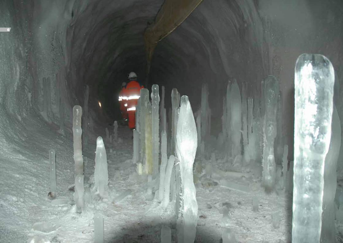
The project consists of a 152 metre cut and cover tunnel on the Aktio side, a 909 metre im-mersed tunnel under the strait and a 509 metre cut and cover tunnel on the Preveza side.
The immersed tunnel is de-signed for two lanes of traffic within a box cross-sectional profile of 10.6 metres internal width. The outer dimensions of the immersed tunnel are 12.6 metres wide by 8.75 metres high.
The eight prefabricated tunnel elements of 59.2 metres to 134.5 metres length were con-structed in a casting basin connected to the strait by an approximately 150 metre long channel. From the casting basin the elements were floated to their final position. The ele-
ments were then installed in a pre-dredged trench.
Before excavation of the trench, 0.6 metres diameter stone columns were constructed in order to prevent liquefaction under possible earthquake loadings.
Flexible joints are provided between the tun-nel elements. The watertightness of the joints is ensured by rubber gaskets. The tunnel elements are further encased in a watertight membrane in order to avoid potential leakage.
The tunnels were designed to withstand se-vere seismic loadings. In comparison to normal immersed tunnels, the shear keys at the joints between the tunnel elements were strength-ened. Furthermore, prestressing cables were placed across the joints in order to limit differ-ential movements during seismic events.
Preveza-Aktio immersed tunnel, Greece
Services
• tenderdesign
• detaileddesign
• constructionfollow-up.
Project period
1993-2002
Client and contractor
JointVenturebetweenChristiani&NielsenLtd.(UK)andTechnicalCompanyofGeneralConstructionsSA(Greece).
36
37

Selected references
Brenner Eisenbahn tunnels, Austria
Description:33kmoftunnelsofanewBrennerfeederrailwayintheInnValley.
Expectedcompletion:2010
Client:BrennerEisenbahnGesellschaft,Austria
ServicesbyCOWI:Vibrationandnoisemeasurementsasabasisforthedesignofdampingmeasuresoftherailwaytracks.
Lyon-Turin rail connection, France/Italy
Description:53kmbasetunnel,a1kmbridgeandanothertunnelof12kmtoreplacetheexistingModane-Frejusmountainline.
Completed:2009
Client:CommissionDG-TREN
ServicesbyCOWI:Independentprojectreview.
Waitemata harbour crossing, New Zealand
Description:1.7kmlongdouble-tube2x3laneimmersedroadtunnel.
WaitemataharbourcrossingfeasibilitystudyofpossibleimmersedtunnelcrossingtheWaitemataharbourinAuckland.
Completed:2004
Client:OpusInternationalConsultantsLtd
ServicesbyCOWI:Specialistassistancetofeasibilitystudy.
Nanjing Yangtze River tunnel project, China
Description:Twin3kmsubseatunnelsinsoftriverdepositsconstructedusingtwo14.5mdiameterslurryTBMs.
Completed:2009
Client:ChinaRailway14thEngineeringCorporationLtd.
ServicesbyCOWI:PreparationofTBMspecification,supervisionofTBMmanufacturing,supervisionofTBMfabricassemblyandtesting,supervisionofsiteassemblyandcommissioningtests,technicalassistanceandsupportduringstartup.
Kaunas Railway Tunnel, Lithuania
Description:1250metrearchtunnelfrom1862rehabilitatedbyinstallingnewconcreteliningwithmembrane,wideningoftheexistingtunnelata100metresection,newdrainagesystem,newballastedtracksandnewrailwaysysteminstallations.
Completed:2009
Client:JSCKelvista
ServicesbyCOWI:Expertassistanceregardingtunneldesignandconstruction.
SR 520 crossing of Lake Washington, Seattle, USA
Description:ImmersedandcutandcovertunneloptionsforpartsofnewcrossingofLakeWashington.
Completed:2009
Client:TheKeystoneCenter,MediatorappointedbyWashingtonState
ServicesbyOCC(COWI):Feasibilitystudy,conceptualdesign,experts’review,constructioncostsestimateandlife-cyclecostsanalysis.
38

Highway overpass
Yedýkule tube tunnel station
Yenýkapi TCDD transfer station
Sýrkecý stationÜsküdar station
Assumed existing ground profileYenýkapi tube tunnel station
Bored tunnel Bored tunnelIMT
0 m
-10 m
-20 m
-30 m
-40 m
-50 m
+10 m
Gevingåsen railway tunnel, Norway
Description:4.4km,64m2single-linerailwaytunnelinCaledoniengreenstoneandschist.ThetunnelwillbeexcavatedbyD&Btechnology.
Expectedcompletion:2011
Client:Jernbaneverket(TheNorwegianRailwayAdministration)
ServicesbyCOWI:Projectmanagerforthedesignandtenderphase.Designandsafetymanagerforthetotalproject.
Lærdal Tunnel, Norway
Description:A24.5kmlongroadtunnel-theworld’slongest.Thetunnelisbi-directionalandisprovidedwith15turningpointsand48breakdownlay-byes.
Completed:2000
Client:NorwegianRoadDirectorate
ServicesbyCOWI:Detaileddesignofelectricalinstallations(electricalpowersystems,controlsystemsandemergencyphonesystemandelectricaldesignofthetunnelventilationsystem).
Fehmarn Belt crossing, Denmark/Germany
Description:Initialphaseoftechnicalandenvironmentalfeasibilitystudyof18.5kmmotorwayandrailwayconnectioncrossingtheFehmarnBelt.
Completed:2008
Client:Sund&BæltA/S
ServicesbyCOWI:Environmentalfeasibilitystudyforatunnelandabridge,respectively.
Coatzacoalcos immersed tunnel, Mexico
Description:Immersedtunnelof830metreswhichcrossestheCoatzacoalcosriver.Thetunnelisatwobytwo-laneroadtunnel.
Expectedcompletion:2010
Client:CalyMayoryAsociados
ServicesbyCOWI:Reviewofdesignandconstruction.
Bosporus crossing, Turkey
Description:13.3kmnewundergroundrailwaylinewith4stationsconsistingof8.2kmboredtunnel,1.8kmcutandcoversectionsand1.8kmimmersedtunnel.
Client:HPYGJV:Hazama(Japan),Penta-Ocean(Japan),Yüksel(Turkey)andGüris(Turkey).
Completed:2004
ServicesbyCOWI:Tenderdesignprogrammemanagement.
Budapest Metro line 4, Hungary
Description:10.5kmtwin-tubetunnelsand14undergroundstationswith11mainconstructioncontracts.
Completed:2007
Client:HungarianCoordinationCentreforTransportDevelopmentIntermediateBody
ServicesbyCOWI:Performatechnicalauditoftheprojectincludinganassessmentoftheprojectorganisation,thecontractmanagement,theconstructioncontracts,thetimescheduleandtheconstructionbudget.
Pho
to:
JW L
uftf
oto
39

Selected referencesGreen Heart Tunnel, The Netherlands
Description:14.5metrediameter,8kmlongboredtunnelthroughthewaterloggedpeatsandsandsofthecentralNetherlands.
Completed:2005
Client:HSL-Zuid-DutchMinistryofTransportandPublicWorks
ServicesbyCOWI:Reviewofdesignandconstructiondocumentationfortheproduction,erectionandrepairoftheprecastsegmentalliningandTBMoperation.
Guldborgsund road tunnel, Denmark
Description:460metresimmersedroadtunnelwithtwolanesanddrainedrampsunderthestraitofGuldborgsund.
Completed:1988
Client:DanishMinistryofPublicRoads,RoadDirectorate
ServicesbyCOWI:Conceptualdesign,tenderdesign,detaileddesignandsupervision.
Shanghai Chongming Yangtze River tunnel project, China
Description:8.3kmtwin-tubeboredroadtunneltobebuiltinsoftriverdepositsusingaworld-recordslurryTBMwitha15.2metrediameter.
Completed:2004
Client:ShanghaiHuchongCrossRiverInvestmentandDevelopmentCo.Ltd.
ServicesbyCOWI:Preliminarydesignincludingsegmentalliningdesign,durabilitydesign,adviseontunnellingmethodsinsoftclayconditions,ventilationandfire-fightingdesign. Lötschberg base tunnel, Switzerland
Description:34.6kmlongtwin-tunnelaspartoftheSwisscross-alpinerailtunnelsfromFrutigentoRaron.Rocktemperaturesofupto45°Careexpected.
Completed:2007
Client:BundesamtfürVerkehr,Switzerland
ServicesbyCOWI:Reviewoftunnelventilationstrategyandconceptdesignreportforemergencyventilation.Suggestionsonalternativedesignandventilationmethods.
Baoshan-Longling expressway, China
Description:Fifteentunnelsvaryingbetween125and2920metresinlength.Thetotaltunnellengthis18.7km.ThetunnelsareSCLtypetunnelsinweatheredrock.
Client:YunnanBaolongExpresswayCo.Ltd.andtheAsianDevelopmentBank
Completed:2008
ServicesbyCOWI:Constructionmanagementassistance,designreviewandinspectionofconstructionmethods.
STEP Deep sewer tunnel, Abu Dhabi
Description:ContractsT-02andT-03oftheSTEPprojectincludesa26kmsewertunnelwithadiameterupto6.3metresandtenshaftswithadepthofmax.75metres,alltotransportwastewatertotreatmentplantsinthearea.
Expectedcompletion:2013
Client:ImpregiloS.p.A.
ServicesbyCOWI:Tenderdesign,detaileddesignandconstructionsupervision.
40

Cut & cover
+20
0
-20
-40
-60
Helsingborg
Trough Cut & coverBored tunnel
0 1 2 3 4 5 6
StationStation
25 ‰
25 ‰
2,5 ‰25 ‰
Elsinore
Upper and middle JurassicLower Jurassic
Postglacial sandPostglacial clayGlacial deposits Water
Fill
Melt water depositsLimestone
Taiwan high-speed rail project, Taiwan
Description:The326kmlongrailwaylinerunsthroughtunnelsandcuts,onembankmentsandonbridgesandviaducts.
Completed:2005
Client:LotC240:Hyundai-ChungLinJV,LotC250:Hochtief-BallastNedam-PanAsiaJV
ServicesbyCOWI:IndependentdesigncheckeroflotsC240andC250.
Copenhagen airport and the Sydhavnsgade tunnel, Denmark
Description:600metrelongcutandcoverstationandapproximately4kmcutandcovertunnelsintotalontheØresundlinkrailwaylinebetweentheCopenhagencentralstationandCopenhagenairport.
Completed:2001
Client:ØresundA/S
ServicesbyCOWI:Forvariouspartsoftheworks:tenderdocuments,detaileddesign,designcheck,constructionmanagement,technicalsupportandsitesupervision.
Fourth Victoria Harbour immersed tunnel, Hong Kong
Description:ImmersedtunnelaspartofanewmetrolineShaTin-CentralLinkwithatotallengthof18kmand11newstations.
Completed:2009
Client:Kowloon-CantonRailwayCorporation
ServicesbyCOWI:Initialdesign,schemedesign,tenderdesign,posttenderassistance.
Lyon line B extension
Description:300metresimmersedtunnelcrossingtheRhôneriver:Onetube,9.6metreswideand6.0metreshigh.
Completed:2008
Client:SYTRAL(asasubconsultanttoEgisRail)
ServicesbyCOWI:Feasibilitystudy,conceptualdesign,costestimate,riskassessments,tenderdocuments,tenderevaluationofimmersedtunnelsolution.
Conwy estuary tunnel, Wales
Description:Dualtwo-lanehighwaytunnelwitha710metrelongimmersedsectionunderthe5-12metresdeepConwyestuary,320metreslongin-situsectionand610metreslongrampsinalluvialsandsandclays.
Completed:1991
Client:TheWelshOffice,TransportationandHighwaysGroup
ServicesbyCOWI:Tenderdesign,detaileddesignandsupervisioninjointventurewithTraversMorgan.
Helsingør-Helsingborg tunnel, Denmark-Sweden
Description:5kmsubsearailwaytunnelbetweenDenmarkandSwedenperformedasatwin-boredtunnel,animmersedtunneloracombinedboredandimmersedtunnel.
Completed:1998
Client:MunicipalitiesofHelsingørandHelsingborg
ServicesbyCOWI:FeasibilitystudyinjointventurewithSCC.
41

Selected referencesChengdu Metro, Sichuan Province, China
Description:TheChengdumetrosystemisplannedtoconsistofseverallines.Thefirstphaseis16kmlongandhas15stations.
Expectedcompletion:2010
Client:ChengduLeadingGroupofMetroConstructionandKreditanstaltfürWiederafbau
ServicesbyCOWI:Specialistadviceregardingundergrounddesign.
Odense small river, Denmark
Description:Asewerageprojecttointerceptoverflowduringrainfromtheoldcombinedsewagesystemtoharbourbasinstoreducepollutionandunpleasantconditionsintheharbour.
Completed:2007
Client:OdenseWaterLtd.
ServicesbyCOWI:Detaileddesign,constructionmanagementandsitesupervision.
George Massey tunnel, Canada
Description:AnengineeringassessmentandsubsequentretrofitprojectwasinitiatedtoincreasethesurvivabilityoftheGeorgeMasseytunnelintheeventofasignificantearthquake.
Completed:2002
Client:MinistryofTransportationandHighways,BritishColumbia,Canada
ServicesbyBuckland&TaylorLtd.andBenC.GerwickInc.(COWI):Seismicretrofitdesign.
The Øresund Link, immersed tunnel, Denmark-Sweden
Desciption:18kmcombinedroadandrailwaylinkacrossthesoundbetweenDenmarkandSwedenincludinga4kmimmersedtunnelsectioninfissuredlimestonetocrossthemainnavigationchannel.
Client:Skanska(SE),MTHøjgaard(DK)andHochtief(D)
Completed:2000
ServicesbyCOWI:Tenderdesign.
Copenhagen airport railway station, Denmark
Description:TheCopenhagenairportrailwaystationcomprisesa600metrerailwaystationandadjoiningtunnelsforadouble-trackedrailway.TheconsultingserviceswereperformedinajointventurewithCOWIasleadpartner.
Completed:1999
Client:ØresundA/S
ServicesbyCOWI:Detaileddesign,constructionmanagementandsitesupervision.
2nd Coen tunnel project, The Netherlands
Description:ImmersedtunneltobeconstructedadjacenttoexistingimmersedtunnelundertheharbourofAmsterdam
Completed:2008
Client:GATEWEST,groupofDutchcontractorsincludingStructon
ServicesbyCOWI:Planningofmethodstoensureexistingtunnelintegrityduringnewtunnelconstruction,renovation,designanddurabilityassessmentofexistingtunnel,andoperationandmaintenancecostestimate.
42

COWI key tunnel staff
AntonPetersenSeniorVicePresident,Bridge,[email protected]
MichaelBindseilSeniorProjectDirectorTunnelandUndergroundStructuresmhb@cowi.com
KnudRené[email protected]
ChristaKjæ[email protected]
EgonA.Sø[email protected]
CasperPaludan-Mü[email protected]
TorstenMø[email protected]
Pho
to: T
hier
ry W
iele
man
fot
ogra
fi
43

021-1700-020e-10b
PrintedinDenmarkbyKailow
COWI tunnel offices
Denmark, head officeCOWIA/SParallelvej2DK-2800KongensLyngbyDenmarkTel. +4545972211www.cowi.com
ChinaCOWIConsultingCo.,Ltd.Suite2010SunflowerTower37MaiZiDianStreet,ChaoYangDistrictBeijing100125P.R.Chinawww.cowi.cn
@www.cowi.com
CanadaBuckland&TaylorLtd.101-788HarboursideDriveNorthVancouverBCV7P3R7Canadawww.b-t.com
KoreaCOWIKoreaCo.,Ltd.711AmigoTower358-2Yatap-dong,Bundang-gu,Seongnam-si,Gyeonggi-do,Koreawww.cowi.co.kr
NorwayCOWIASGrenseveien880605OsloNorwaywww.cowi.no
SwedenCOWIABSkärgårdsgatan1S-41458GöteborgSwedenwww.cowi.se
United KingdomFlint&NeillLimitedBridgeHouse4BoroughHighStreetLondonSE19QQUnitedKingdomwww.flintneill.com
USAOceanandCoastalConsultantsInc.35CorporateDriveTrumbull,CT06611,USAwww.ocean-coastal.com
USABenC.Gerwick,Inc.1300ClayStreet7thFloorOakland,CA94612UnitedStateswww.gerwick.com
Middle EastCOWIGulfA/SReemasBuildingOfficeMF-10AlQuoz1Dubai,UAEwww.cowi.ae