GE-02-502 Geotechnical and Structural Instrumentatino for ... Geotechnical... · and-cover tunnels,...
50
PDH-Pro.com 396 Washington Street, Suite 159, Wellesley, MA 02481 Telephone – (508) 298-4787 www.PDH-Pro.com This document is the course text. You may review this material at your leisure before or after you purchase the course. In order to obtain credit for this course, complete the following steps: 1) Log in to My Account and purchase the course. If you don’t have an account, go to New User to create an account. 2) After the course has been purchased, complete the quiz at your convenience. 3) A Certificate of Completion is available once you pass the exam (70% or greater). If a passing grade is not obtained, you may take the quiz as many times as necessary until a passing grade is obtained (up to one year from the purchase date). If you have any questions or technical difficulties, please call (508) 298-4787 or email us at [email protected]. Geotechnical and Structural Instrumentation for Road Tunnels Course Number: GE-02-502 PDH: 4 Approved for: AK, AL, AR, GA, IA, IL, IN, KS, KY, MD, ME, MI, MN, MO, MS, MT, NC, ND, NE, NH, NJ, NM, NV, OH, OK, OR, PA, SC, SD, TN, TX, UT, VA, WI, WV, and WY New Jersey Professional Competency Approval #24GP00025600 North Carolina Approved Sponsor #S-0695
Transcript of GE-02-502 Geotechnical and Structural Instrumentatino for ... Geotechnical... · and-cover tunnels,...

PDH-Procom
396 Washington Street Suite 159 Wellesley MA 02481 Telephone ndash (508) 298-4787 wwwPDH-Procom
This document is the course text You may review this material at your leisure before or after you purchase the course In order to obtain credit for this course complete the following steps 1) Log in to My Account and purchase the course If you donrsquot have an account go to New User to create an account 2) After the course has been purchased complete the quiz at your convenience 3) A Certificate of Completion is available once you pass the exam (70 or greater) If a passing grade is not obtained you may take the quiz as many times as necessary until a passing grade is obtained (up to one year from the purchase date) If you have any questions or technical difficulties please call (508) 298-4787 or email us at adminPDH-Procom
Geotechnical and Structural Instrumentation for Road Tunnels
Course Number GE-02-502
PDH 4
Approved for AK AL AR GA IA IL IN KS KY MD ME MI MN MO MS MT NC ND NE NH NJ NM NV OH OK OR PA SC SD TN TX UT VA WI WV and WY
New Jersey Professional Competency Approval 24GP00025600 North Carolina Approved Sponsor S-0695
US Department of Transportation Publication No FHWA-NHI-10-034 Federal Highway Administration December 2009
Technical Manual for Design and Construction of Road Tunnels mdash Civil Elements
NOTICE
The contents of this report reflect the views of the authors who are responsible for the facts and the accuracy of the data presented herein The contents do not
necessarily reflect policy of the Department of Transportation This report does not constitute a standard specification or regulation The United States Government
does not endorse products or manufacturers Trade or manufacturers names appear herein only because they are considered essential to the objective of this
document
Technical Report Documentation Page 1 Report No
FHWA-NHI-10-034
2 Government Accession No 3 Recipientrsquos Catalog No
4 Title and Subtitle
TECHNICAL MANUAL FOR
DESIGN AND CONSTRUCTION OF ROAD TUNNELS ndash CIVIL ELEMENTS
5 Report Date
December 2009 6 Performing Organization Code
7 Author(s)
Principal Investigators C Jeremy Hung PE James Monsees PhD PE Nasri Munfah PE and John Wisniewski PE
8 Performing Organization Report No
9 Performing Organization Name and Address
Parsons Brinckerhoff Inc One Penn Plaza New York NY 10119
10 Work Unit No (TRAIS)
11 Contract or Grant No
DTFH61-06-T-07-001
12 Sponsoring Agency Name and Address
National Highway Institute US Department of Transportation Federal Highway Administration Washington DC 20590
13 Type of Report and Period Covered
14 Sponsoring Agency Code
15 Supplementary Notes
FHWA COTR ndash Louisa Ward Larry Jones FHWA Task Manager ndash Firas I Sheikh Ibrahim PhD PE FHWA Technical Reviewers ndash Jesuacutes M Rohena y Correa PE Jerry A DiMaggio PE Steven Ernst
PE and Peter Osborn PE See Acknowledgement for List of Authors and Additional Technical Reviewers 16 Abstract
The increased use of underground space for transportation systems and the increasing complexity and constraints of constructing and maintaining above ground transportation infrastructure have prompted the need to develop this technical manual This FHWA manual is intended to be a single-source technical manual providing guidelines for planning design construction and rehabilitation of road tunnels and encompasses various types of road tunnels including mined bored cut-and-cover immersed and jacked box tunnels The scope of the manual is primarily limited to the civil elements of road tunnels
The development of this technical manual has been funded by the National Highway Institute and supported by Parsons Brinckerhoff as well as numerous authors and reviewers
17 Key Words
Road tunnel highway tunnel geotechnical investigation geotechnical baseline report cut-and-cover tunnel drill-and-blast mined tunnel bored tunnel rock tunneling soft ground tunneling sequential excavation method (SEM) immersed tunnel jacked box tunnel seismic consideration instrumentation risk management rehabilitation
18 Distribution Statement
No restrictions
19 Security Classif (of this report)
UNCLASSIFIED
20 Security Classif (of this page)
UNCLASSIFIED
21 No of Pages
702
22 Price
Form DOT F 17007(8-72) Reproduction of completed page authorized
CONVERSION FACTORS
Approximate Conversions to SI Units Approximate Conversions from SI Units
When you know Multiply by To find When you know Multiply by To find
(a) Length inch 254 millimeter millimeter 0039 inch foot 0305 meter meter 328 foot
yard mile
0914 161
meter kilometer
meter kilometer
109 0621
yardmile
(b) Area square inches
square feet acres
6452 0093 0405
square millimeters square meters
hectares
square millimeters square meters
hectares
00016 10764
247
square inches square feet
acres square miles 259 square kilometers square kilometers 0386 square miles
(c) Volume fluid ounces 2957 milliliters milliliters 0034 fluid ounces
gallons cubic feet
3785 0028
liters cubic meters
liters cubic meters
0264 3532
gallonscubic feet
cubic yards 0765 cubic meters cubic meters 1308 cubic yards
(d) Mass
ounces pounds
short tons (2000 lb)
2835 0454 0907
grams kilograms
megagrams (tonne)
grams kilograms
megagrams (tonne)
0035 2205 1102
ounces pounds
short tons (2000 lb)
(e) Force pound 4448 Newton Newton 02248 pound
(f) Pressure Stress Modulus of Elasticity pounds per square foot pounds per square inch
4788 6895
Pascals kiloPascals
Pascals kiloPascals
0021 0145
pounds per square foot pounds per square inch
(g) Density
pounds per cubic foot 16019 kilograms per cubic meter kilograms per cubic meter 00624 pounds per cubic feet
(h) Temperature Fahrenheit temperature(oF) 59(oF- 32) Celsius temperature(oC) Celsius temperature(oC) 95(oC)+ 32 Fahrenheit temperature(oF) Notes 1) The primary metric (SI) units used in civil engineering are meter (m) kilogram (kg) second(s) newton (N) and pascal (Pa=Nm2) 2) In a soft conversion an English measurement is mathematically converted to its exact metric equivalent 3) In a hard conversion a new rounded metric number is created that is convenient to work with and remember
FOREWORD The FHWA Technical Manual for Design and Construction of Road Tunnels ndash Civil Elements has been published to provide guidelines and recommendations for planning design construction and structural rehabilitation and repair of the civil elements of road tunnels including cut-and-cover tunnels mined and bored tunnels immersed tunnels and jacked box tunnels The latest edition of the AASHTO LRFD Bridge Design and Construction Specifications are used to the greatest extent applicable in the design examples This manual focuses primarily on the civil elements of design and construction of road tunnels It is the intent of FHWA to collaborate with AASHTO to further develop manuals for the design and construction of other key tunnel elements such as ventilation lighting fire life safety mechanical electrical and control systems FHWA intends to work with road tunnel owners in developing a manual on the maintenance operation and inspection of road tunnels This manual is expected to expand on the two currently available FHWA publications (1) Highway and Rail Transit Tunnel Inspection Manual and (2) Highway and Rail Transit Tunnel Maintenance and Rehabilitation Manual
M Myint Lwin Director Office of Bridge Technology
CHAPTER 15 GEOTECHNICAL AND STRUCTURAL INSTRUMENTATION
151 INTRODUCTION In the context of this manual the primary purpose of geotechnical and structural instrumentation is to monitor the performance of the underground construction process in order to avoid or mitigate problems If such monitoring also serves a scientific function or leads to advancement in design procedures that is a bonus rather than a primary reason for its implementation A few decades ago monitoring was not a particularly easy task because the tools were few and some not so well developed Monitoring was generally performed manually and the refining of data to a state of usability from the raw readings often required long hours of ldquonumber crunchingrdquo with relatively crude calculators and more long hours of plotting charts and graphs by hand The world of the early 21st century is very different for those who pursue the art of determining what ongoing construction is doing to its surroundings or even to itself Advanced and refined types of instrumentation abound and electronics coupled with computers has made remote monitoring even from half a world away practically an everyday affair It is common for even medium sized projects to run a computerized database that reduces raw readings to usable data and can report on any combination of instruments and data plots within minutes It can also inform interested parties any time of the day or night if movements or stresses have reached pre-set trigger levels that demand some kind of mitigative action The possibilities have not gone unnoticed by project Owners and comprehensive instrumentation and monitoring programs are becoming the norm rather than the exception This is perhaps especially true in the world of tunneling where even small mis-steps can result in damage that may lead to lawsuits or the shutting down of operations Readers should be aware that much of the instrumentation described herein may not lend itself particularly well to rural highway tunnels especially those located in hilly or mountainous terrain that may limit the need for instrumentation if great tunnel depth minimizes ground settlement at the surface and if lack of surface development minimizes the number of third-party abutters who could be affected by construction Also even if a tunnel does require monitoring for whatever reason great depth may minimize possibilities for damage to surface installations and push designers and constructors toward more in-tunnel installations The amazingly large number of instrument types available to tunnelers means that this chapter can do little more than ldquobroad brushrdquo the subject The most common andor most promising types of instrument will be covered but readers will have to turn to the references to see what else is available A few types will be covered to some degree in other chapters for example earth pressure cells that are commonly used by those who specialize in Sequential Excavation Method (SEM) tunneling (Chapter 9) but are not so much used by those who work in other types of underground construction Although vibration monitoring will be covered herein the monitoring of noise will not be covered because it is normally considered an environmental rather than a structural or geotechnical concern Some instruments such as those used to determine in-situ ground stresses prior to tunneling will not be covered because they more rightly belong in the category of site investigation instrumentation And finally there will not be space to delve deeply into the theory of operation of the various instruments discussed so readers will again have to turn to the referenced publications for more details
FHWA-NHI-09-010 15- Instrumentation Road Tunnel Manual 15-1 March 2009
The first few sections of this chapter will discuss the types of measurements typically made bull Ground Movement away from the tunnel bull Building Movement for structures within the zone of influence bull Tunnel movement of the tunnel being constructed or adjacent tubes bull Dynamic Ground Movement from Drill amp Blast bull Groundwater Movement and Pressure due to changes in the water percolation pattern The first three items comprise quasi-static changes in position and the last is also concerned with long-term effects In contrast Dynamic Ground Movement covers response due to vibration caused by the shock waves generated by explosive charges used to excavate rock All of the monitoring needs to be coordinated to fit with the tunnel construction schedule and to establish the actions that must be taken in response to the instrumentation findings These topics are discussed in the final section of this chapter
152 GROUND MOVEMENTS ndash VERTICAL amp LATERAL DEFORMATIONS
1521 Purpose of Monitoring The primary purpose for monitoring ground movements is to detect them while they are still small and to modify construction procedures before the movements grow large enough to constitute a real problem by affecting either the advancing excavation or some contiguous existing facility For the advancing excavation ground support has to be based on conditions encountered monitoring either confirms the adequacy of the support or indicates whether more or different support may be required Existing facilities may be at the ground surface ndash roads railroads buildings and the like ndash or they may be below ground in the form of utilities or other transportation tunnels such as subways The first line of defense against potentially damaging movements is to detect them at depth in the ground immediately surrounding the advancing tunnel and take mitigative action before those movements can ldquopercolaterdquo upward toward the surface This kind of monitoring can provide an indication of whether ground treatment such as grouting is effectively limiting movements that might otherwise result in troublesome settlements Ground can of course move upward as well as downward in the form of heave from unloading that can destabilize the invert of the tunnel under construction and as a side effect lead to lateral possibly damaging deformations as the ground moves toward the excavation to take up the slack In addition to helping control the ground the data developed can be used (and this may be said of all monitoring discussed in succeeding paragraphs) to verify design assumptions and to evaluate claims by construction contractors and third-party abutters
1522 Equipment Applications Limitations Several types of instrumentation are used to monitor ground movement bull Deep Benchmarks bull Survey Points bull Borros Points bull Probe Extensometers bull Fixed Borehole Extensometers either measured from the surface or during advance of the tunnel bull Telltales or Roof Monitors bull Heave Gages
FHWA-NHI-09-010 15- Instrumentation Road Tunnel Manual 15-2 March 2009
bull Conventional Inclinometers bull In-place Inclinometers bull Convergence Gages
15221 Deep Benchmarks Deep Benchmarks (Figure 15-1) are steel pipescasings drilled into stable strata ndash preferably sound bedrock ndash outside the advancing tunnelrsquos zone of influence They are used when existing benchmarks such as those installed by the USGS are not available and it is important to know actual elevation changes of other instruments meant to detect movements If installed close to the construction deep benchmarks need to be carried below invert They must be absolutely stable in spite of any ground movements that are occurring because it is the surface level collars of these devices that become the unmoving points from which locations and elevations of other instruments can be determined by surveying A major complication in the installation of benchmarks can be the difficulty of installing them in a location andor to a depth that absolutely guarantees no movement as tunneling proceeds In this regard the lowering of groundwater in a soft ground environment can contribute to ground settlements well outside the immediate projected footprint of the advancing tunnel so the instrument has to be well placed to guard against this eventuality In cases of very large projects or overlapping projects that cause the water table to be drawn down across a large area benchmarks have been known to settle even when founded in bedrock because some rock types can be dependent to a degree on pore water pressure for their ability to carry load
Figure 15-1 Deep Benchmark
FHWA-NHI-09-010 15- Instrumentation Road Tunnel Manual 15-3 March 2009
15222 Survey Points
Survey Points are used to detect ground movements at the surface or a few feet below the surface They may be as simple as wooden stakes driven into the ground and their elevations surveyed through backsighting to a deep benchmark (Figure 15-2) Penetration needs to be at least a foot or so to guard against dislodgment and the tops should not extend high enough to interfere with mowing machines if they are in a grassy area that requires routine maintenance A survey point may also be somewhat more sophisticated and take the form of a steel rod with a rounded reference head driven several feet into the ground for better avoidance of possible dislodgment and surface effects such as frost heave (See Figure 15-3) This type of point needs to be protected at the surface by a small utility type roadbox with a secured cover so there is no disturbance to the rounded head A rounded head is considered best because a surveyor can then always find the high point that has been surveyed in the past for good continuity in the readings Because there is no hard connection between the rod and the roadbox ndash the one sort of ldquofloatsrdquo inside the other ndash the survey point is also protected from being pushed down in case of the passage of a heavy vehicle The major concerns with any type of survey point is the need to keep it out of the way of other users of the area and also protected against damage that may require replacement and lead to loss of continuity between the latest reading and the string of readings taken in the past
Figure 15-2 Survey Point
FHWA-NHI-09-010 15- Instrumentation Road Tunnel Manual 15-4 March 2009
Figure 15-3 Survey Point in Rigid Pavement Surface
15223 Borros Points A Borros Point is basically an anchor at the lower end of a driven pipe (See Figure 15-4) The anchor consists of three steel prongs housed within a short length of steel pipe with points emerging from slots in a conical drive point Installation is achieved by advancing a borehole in soft ground to a few feet above the planned anchor depth and the anchor inserted by attaching extension lengths of riser pipe and outer pipe When the point reaches the bottom of the hole it is driven deeper by driving on the top of the outer pipe The prongs are then ejected by driving on the riser while the prongs are released and the outer pipe bumped back a short distance to achieve a positive anchorage Such installations are useful for determining the amount of settlement at one precise depth with more certainty than the simple driven steel rod described above and they are relatively simple and economical The amount of anchor movement is determined by surveying or otherwise measuring the movement of the inner riser pipe at the ground surface One disadvantage with such movement detection (and this can be said of most instruments whose data depends on movements measured in a surface mounted reference head) is that if settlement is great enough to have affected the surface at reading time then the whole instrument may be moving downward by a certain amount while the anchor is moving downward by a greater amount Absolute anchor movement may then be difficult to judge unless ground elevation surveys are undertaken at that time and the changes added to the apparent anchor movement
FHWA-NHI-09-010 15- Instrumentation Road Tunnel Manual 15-5 March 2009
Figure 15-4 Schematic of Borros Point (After Dunnicliff 1988 1993)
15224 Probe Extensometers Probe Extensometers are used to measure the change in distance between two or more points within a drilled hole in soft ground through use of a portable probe containing an electrical transducer As shown in Figure 15-5 the probe which contains a reed switch is inserted into a casing in the drill hole in which the reference points each of which contains an array of bar magnets have been fixed in a way to surround the casing on the outside In the most common type of installation the reference points are held in place by spring loaded anchors ndash leaf springs ndash that rdquobiterdquo into the ground The points are free to move with the ground because the outer support casing will have been removed and replaced by grout The probe detects the depth of the reference points for an indication of whether the soil at those depths is settling due to disturbance from construction A probe extensometer can thus measure the settlements at a much larger number of depths than can a Borros Point Probe extensometers are generally drilled to a depth below any potential zone of influence near a cut-and-cover or mined tunnel The bottom reference point then becomes the unmoving reference from which the movements of the shallower points are judged In a typical situation near a mined tunnel it is likely that the lowest moving point will exhibit the most settlement and that settlements will prove to be less as the probe moves up the casing to where the settlement trough is widening One problem with probe extensometers is that collection of data can be operator sensitive as the instrument reader strains to detect the exact location of the probe at each reference point depth by listening for the electronic ldquobeeprdquo to ensure readings at precisely the same spot time after time Another concern may be the time required for monitoring especially if a large number of reference points have been installed because the probe does have to be lowered to the bottom of the casing and then readings collected as it is slowly winched back to the surface
FHWA-NHI-09-010 15- Instrumentation Road Tunnel Manual 15-6 March 2009
Figure 15-5 Schematic of Probe Extensometer with MagnetReed Switch Tansducer Installed in a Borehole (After Dunnicliff 1988 1993)
15225 Fixed Borehole Extensometers Installed from Ground Surface Fixed Borehole Extensometers installed from ground surface may be used in soft ground or rock and may be Single Position (SPBX) for settlement measurements at one specific elevation or Multiple Position (MPBX) for measurements at several elevations Figure 15-6 illustrates a schematic of an MPBX The anchors of a borehole extensometer are grouted into the ground commonly at various distances above the crown of an advancing tunnel and connected to surface mounted reference heads by small diameter rods of steel or fiberglass By detecting movement of the tops of the rods at the surface one can tell how much each anchor ndash and hence its increment of soil or rock ndash is moving in response to excavation and so take steps to mitigate developing problems Manual readings can be taken in a matter of minutes assuming there is no problem with access to the instrument collar However automatic readings with an electrical transducer and datalogger ndash which can be salvagedmoved for use on other instruments ndash are relatively inexpensive and can provide real time data that feeds directly and quickly into a computer for fast analysis and databasing Although extensometers oriented vertically over mined tunnel crowns are the most common installations two others may prove useful in particular situations (a) instruments angled in toward tunnel crowns or haunches from sidewalks where vertical installations are precluded by heavily travelled roads and (b) instruments installed along the sidewalls of mined tunnels or cut-and-cover excavations where a knowledge of the vertical component of overall ground movement may be advantageous A common problem with manually read instruments is the one of operator sensitivity and if more than one reader is employed they need to practice together to make certain they can monitor with good consistency Remote monitoring leads to the concern that data collectors and analyzers may without themselves personally having an eye on the construction operation be unaware of the type and scheduling of activities that are affecting the data Hence it may be necessary to make arrangements for construction progress reports to be delivered on a tighter schedule than otherwise might be necessary
FHWA-NHI-09-010 15- Instrumentation Road Tunnel Manual 15-7 March 2009
Figure 15-6 Multiple Position Borehole Extensometer Installed from Ground Surface
15226 Fixed Borehole Extensometers Installed from Advancing Excavations Fixed Borehole Extensometers installed from advancing excavations are a fairly obvious need if sidewall movements are required for a cut-and-cover excavation Such horizontal installations are common and the drillinginstalling operation has to mesh with the construction so that the larger operation is not overly impacted by what may appear to be a peripheral activity (Note ldquoHorizontalrdquo installations are seldom truly horizontal because angling downward by 10 or 15 degrees makes it much easier to manage the grouting of the anchors) The installation of extensometers oriented from the vertical to the horizontal ndash including all angles in between ndash from inside advancing mined rock tunnels may be mandated by the lack of access from the ground surface (Figure 15-7) If possible they are normally installed just behind a tunnel working face or the tail shield of a TBM In this position they can provide data on incipient fallouts or more subtle rock movements toward the opening If installed where a small tunnel is to be enlarged to greater size at a later time the instrument heads can be recessed beyond the initial excavation outline and saved for use in monitoring the larger excavation In this way they provide an almost
FHWA-NHI-09-010 15- Instrumentation Road Tunnel Manual 15-8 March 2009
complete history of rock movements from the earliest to the latest point in time Another way to use these instruments is to install them from a first driven tunnel toward the location of a following twin tunnel Readings then indicate whether the pillar between the two tunnels is loosening so that steps can be taken to mitigate the problem
Figure 15-7 Horizontal Borehole Extensometer Installed from Advancing Excavation
Complications for these in-tunnel instruments are more numerous than for those installed from somewhere outside the excavation As noted the installation has to be meshed with the construction operation a particularly tricky proposition in the confines of a small mined tunnel where constructor complaints of interference are extremely common Even the collection of data if it is performed manually may be obtrusive especially if cessation of tunneling use of ladders or help from constructor personnel are involved Remote monitoring is also possible but then there is electrical wiring to be run and the need to find a place for the datalogger(s) to be out of the way By whatever method the in-tunnel instruments are monitored the reference heads need to be protected often by countersinking them in the tunnel wall and perhaps through installation of protective covers This is especially true where there is going to be more blasting in the vicinity but also true even where blasting is not involved Miners tend to have little reverence for objects whose importance is not obvious to them so vandalism and theft of instrument accoutrements has to be guarded against Finally there is the fact that an in-tunnel instrument is almost always installed after the tunneled ground has started to relax so the initial readings are seldom true zero points from which to compute follow-on movements The instrumentation specialistrsquos only recourse is to continually press the constructor for access to install instruments at the earliest possible opportunity
15227 Telltales or Roof Monitors Telltales or Roof Monitors (Figure 15-8) are other devices that can be installed from inside an advancing rock tunnel They are designed to be installed with anchors in stable rock beyond the tips of rock bolts in tunnel roofs to provide fast feedback on stability The immediate safety of the minerstunnelers is the primary reason for the instrumentrsquos use The devices were pioneered in French coal mines in the 1970s and further refined by the British and others in succeeding years The first ones were steel rods with a single anchor and visual movement indicators in the tunnel roof that could be seen by miners as they worked Simple and installable by rock bolting crews they proved vulnerable to shearing due to movement of rock blocks and were eventually replaced by more flexible steel wires that are less prone to failure Modern versions have as many as three anchors and can be wired for remote reading by a trained person watching the data on a laptop computer Roof monitors are widely used around much of the world and are gaining acceptance in the US where they deserve to join the ranks of commonly used FHWA-NHI-09-010 15- Instrumentation Road Tunnel Manual 15-9 March 2009
instruments They are now used in civil as well as mine construction and also in rock other than flat lying sedimentaries commonly associated with coal seams As of this writing the primary factor in considering use of roof monitors in the US may be the need to educate tunnel designers and constructors in their efficacy and ease of use
Figure 15-8 Triple Height Telltale or Roof Monitor
15228 Heave Gages Heave Gages are most commonly used when excavating for open cut or cut-and-cover in soft clay where there is potential for the bottom to fail by heaving as overburden load is removed There are several instruments with which heave can be detected and measured but almost all either suffer from lack of accuracy or are prone to damage or malfunction Interestingly the magnetreed switch gage packaged as for a probe extensometer is probably the best alternative (Figure 15-9) In this type of installation the user measures increasing rather than decreasing distances between spider magnets and a fixed bottom anchor With care taken to make certain the bottom anchor is well below any expected zone of movement the installation is made inside the cofferdam prior to start of excavation After initial readings are taken the access pipe is sealed 5 to 10 feet below the ground surface through use of an expanding plug set with an insertion tool and the pipe is cut with an internal cutting tool just above the plug A good fix is made on the plan location of the instrument and just before the excavation reaches the plug the pipe is located a reading made and the pipe again sealed and cut The procedure is repeated until excavation is complete The concern with such installations ndash a concern not overcome with alternative installation types ndash is that any large excavation is made by means of heavy equipment and operators are not prone to watching and caring for things as small as a heave gage pipe It is common for the gages to be damaged beyond use
FHWA-NHI-09-010 15- Instrumentation Road Tunnel Manual 15-10 March 2009
and their protection can be assured only through some forceful construction management and sometimes the levying of penalties for instruments damaged as a result of contractor carelessness
Figure 15-9 Heave Cage
15229 Conventional Inclinometers As shown in Figure 15-10 conventional Inclinometers are aluminum or plastic casings drilled vertically to below the level of construction into a stable stratum and used to determine whether the surrounding ground either rock or unconsolidated material is moving laterally toward the excavation Each casing has tracking grooves to guide the sensing probe for orientation both parallel to and at right angles to the axis of the excavation The probe which contains tilt sensors is lowered on a graduated cable to the bottom of the hole and winched upward with stops at 2-foot intervals for collection of inclination data by means of a readout unit at the ground surface An iterative process of tilt calculations from the unmoving bottom of the casing permits plotting of a profile that fixes each measured increment of casing in space in relation to the excavation An initial set of inclination readings is taken before excavation begins and each set of readings thereafter during construction provides data on how the ground is moving when the user plots the newer movement curves against the initial pre-construction curves The inclinometers are normally situated a few feet from the excavation periphery of open cut or cut-and-cover excavations but may also be installed just outside a mined tunnel where lateral movement data may be combined with vertical movement data from the extensometers discussed above The term ldquoconventional inclinometerrdquo is used herein to distinguish the manually read instrument from the ldquoin-placerdquo instruments described below The major concern with a conventional inclinometer is the time consumed in the monitoring process Readings are performed twice in each monitoring visit once with the probe inserted in the ldquoArdquo direction tracking grooves then again with the probe in the ldquoBrdquo direction A ldquocheck sumrdquo procedure is carried out by examining the sum of the two readings at the same depth 180 degrees apart in order to remove any long term drift of the transducers from the calculations It commonly requires 45 or so minutes for a reader to collect data from a 100-foot deep instrument and that is assuming no indication of
FHWA-NHI-09-010 15- Instrumentation Road Tunnel Manual 15-11 March 2009
excessive movements which if discovered may require another set of readings for confirmation that the movements are real and not due to a reading error or instrument malfunction
Figure 15-10 Principal of Conventional Inclinometer Operation (After Dunnicliff 1988 1993)
152210 In-Place Inclinometers In-Place Inclinometers are typically used for monitoring subsurface deformations around excavations when rapid monitoring is required or when instrumented locations are difficult to access for continued manual readings The sensors are computer driven gravity-sensing transducers joined in a string by articulated rods and they can be installed equidistantly in the casing or concentrated in zones of expected movement (Figure 15-11) With the in-place instrument as many as ten or twelve sensors are mounted in the casing and left semi-permanently in place A larger number of sensors would be difficult to install in a standard size drill hole because each sensor has its own set of signal wires that take up space and a very large number of sensors could result in the need for an uneconomically large diameter drill hole Signals are fed to a datalogger at the surface and can be collected as often as required or even fed by telephone line to the database computer for something close to real time monitoring Compared with conventional instruments the in-place inclinometer hardware is expensive and complex This can sometimes be compensated to a degree by removing sensors from a bypassed instrument and installing them in a new location as the excavation progresses A not-so-easily-overcome disadvantage of the in-place instrument lies in the fact that if there is any long term drift in any of the sensors it cannot be overcome through the check sums procedure described above It is also true that the somewhat limited number of sensors in a standard in-place installation leads to a less smooth plot of movements compared with what can be achieved with the conventional inclinometer
FHWA-NHI-09-010 15- Instrumentation Road Tunnel Manual 15-12 March 2009
Figure 15-11 In-Place Inclinometer
152211 Convergence Gages Convergence Gages may be used for monitoring closure of the ground across either open excavations or mined tunnels In the first instance they perform a function similar to an inclinometer although with many fewer data points to give a full picture of movements In the second function they detect the load redistribution during and after excavation and the extent to which resulting structureground interaction affects the tunnel shape and the lining Until now the typical gage has been a Tape Extensometer which includes a steel tape with holes punched at 50 mm intervals (see Figure 15-12) Anchors that define monitoring points consist of eyelets on the ends of grouted rebar sections that extend into the ground for a foot or so (Figure 15-13) The tension in the tape is controlled by a compression spring and standardization of tension is achieved by rotating the collar until scribed lines are in alignment After attachment of the extensometer to the anchors and standardization of the tension readings of distances are made by adding the dial indicator reading to the tape reading In a typical mined tunnel the pattern of anchors includes one in each sidewall at springline level and one as close as possible to the center of tunnel crown Three readings are taken in a tent shaped pattern and the results indicate whether the tunnel support is behaving in a predictable way For very large tunnels the patterns may be more like trapezoids or overlapping triangles which requires the installation of additional anchors Such readings are only relative readings and if absolute elevation changes are needed this is usually accomplished by surveying the anchor that is in the crown (Installation directly in the high point of the crown is seldom possible because of the presence of the ventilation and other lines)
FHWA-NHI-09-010 15- Instrumentation Road Tunnel Manual 15-13 March 2009
Figure 15-12 Tape Extensometer Typical Detail
Figure 15-13 Typical Convergence Bolt Installation Arrangement
Whether the tunnel is conventionally mined or excavated by TBM it is important to install anchors and begin readings at the earliest practicable time before the ground has begun to ldquoworkrdquo Unfortunately this cannot always be accomplished especially in a TBM tunnel because even if the anchors can be installed in a timely manner there are scores or even hundreds of feet of trailing gear that make the stretching of a tape extensometer essentially impossible This means that measurements may not begin until the machine is a long way past the monitoring point and knowledge of total from-the-beginning movements cannot be obtained For this reason it seems likely that an alternative to the tape extensometer is going to be the best choice for future monitoring of tunnel convergence and it will be in the form of a distometer The device is small hand held and can be used to very accurately determine distances to a target by emitting a laser or infrared beam that is reflected from the target and detected by the same device By installing brackets or bolts that also include targets at the places where tape extensometer eyelets would normally be placed monitoring personnel can detect the changing shape of a tunnel without having to stretch a physical connection between points There remains the problem that a physical object ndash such as TBM trailing gear ndash between targets will interfere with the distometer lines of sight and still not permit
FHWA-NHI-09-010 15- Instrumentation Road Tunnel Manual 15-14 March 2009
measurements in the standard tent shape By judicious placement of additional brackets and targets at monitoring sections it should be possible to gather data by working around the trailing gear in a TBM tunnel with patterns of measurements more like the afore mentioned trapezoids or overlapping triangles
153 MONITORING OF EXISTING STRUCTURES
1531 Purpose of Monitoring If the different parts of a structure should move uniformly by even large amounts damage could be minimal maybe non-existent except perhaps for penetrating utilities such as water pipes that might not be able to accommodate themselves to such movements However most structures affected by construction react by exhibiting more movement of the parts closest to the excavation than of the parts that are further away This differential movement is the principal cause of construction related damages because the affected structure may be subjected to forces it was not designed for A building for example whose footings are settling on one side while the other side settles less or not at all will suffer tilting of some walls and the racking that ensues may cause cracking or spalling of some architectural features freezing of doors and windows or in the worst case failure of one or more of the structural members A bridge whose footings are subjected to differential movements may undergo extensions that literally tear it apart In general the detection of settlements is the first line of defense in the protection of existing facilities whether they be surface (roadways buildings bridges) or subsurface (utilities transit tunnels other highway tunnels) The detection of tilting can also be useful and has become more common as the development of monitoring devices has proceeded in the direction of increased automation The simplest kind of monitoring involves the detection and the tracking of joint separations and crack propagation in structural concrete or architectural finishes The ideal is to detect and mitigate some or all of these movements before they have become severe enough to cause serious damage or perhaps constitute a hazard
1532 Equipment Applications Limitations As with ground movement instrumentation there are a number of choices of instrumentation bull Deformation Monitoring Points bull Structural Monitoring Points bull Robotic Total Stations bull Tiltmeters bull Utility Monitoring Points bull Horizontal Inclinometers bull Liquid Level Gages bull Tilt Sensors on Beams bull Crack Gages
15321 Deformation Monitoring Points Deformation monitoring points on roads streets or sidewalks can be as simple as paint marks that get surveyed on a routine basis However paint has the disadvantage that it can be visually obtrusive may wear off with time and may not display a single spot that surveyors can return to time after time for good
FHWA-NHI-09-010 15- Instrumentation Road Tunnel Manual 15-15 March 2009
data continuity A better alternative is a small bolt-like devise set in an expansion sleeve that can be installed in a small hole drilled in concrete or asphalt as shown in Figure 5-14 The point should have a slightly protruding rounded head with a consistent high point that is always findable by a surveyor as he or she searches for the same unchanging spot on which to set the stadia rod It is important that the point not protrude too much because it might then become a tripping hazard or be vulnerable to damage from equipment such as snow plows Although they are inexpensive to purchase and install the ultimate cost of deformation monitoring points can grow to become relatively high if data collection becomes intensive because it depends upon the mobilization of survey crews Also such monitoring is not always foolproof because surveyors are not necessarily attuned to the need for that high degree of accuracy that is sought by instrumentation specialists It is very common for data thus generated to exhibit a fair amount of ldquoflutterrdquo ie apparent up-down movements that are not real but are only the result of inconsistencies in the survey process Such inconsistencies may result from the too-often changing of personnel in survey crews changes that happen commonly due to the nature of the business Luckily extreme accuracy is not required in much of this paved surface monitoring so if the surveyors can reliably detect changes of one-quarter inch or so that is often good enough
Figure 15-14 Deformation Monitoring Point in Masonry or Concrete Slab
15322 Structural Monitoring Points Structural Monitoring Points are survey points that are placed directly on the structures of concern most often being installed on a vertical wall of a building or a structural element of a bridge (See Figure 15-15) Except for buildings most structures can accommodate the monitoring point likely to do the best job and the ldquopointsrdquo may take several forms The simplest is a tiny scratch mark that can be easily found on each monitoring visit by a survey crew A similar point is a stick-on decal target which is a bit more obtrusive but easily removable once it is no longer needed A problem with such surface treatments is that for buildings particularly the monitoring point may be only on a facade that moves independently of the underlying structural elements whose movements it is important to detect This may be overcome by the installation of a bolt-like device that penetrates to the underlying structure for a truer indication of the FHWA-NHI-09-010 15- Instrumentation Road Tunnel Manual 15-16 March 2009
movements taking place The choice of monitoring points will often depend on the wishes of owners or managers of buildings who may object to the visual obtrusiveness or potential for damage from whatever may be installed Possible damage can extend to the post-construction period when the monitoring point may have to be removed and patched something that is often insisted on by the party who permitted its installation Thus it may be necessary to repair the scars left by the removal which may entail the use of solvents infilling spackling polishing painting or replacement for satisfactory restoration
Figure 15-15 Structure Monitoring Point in Vertical Masonry or Concrete Surface
A large consideration in the use of structural monitoring points is the need to depend upon surveyors for the collection of data Compared with roads and sidewalks most structures have tight specifications on permissible movements (a lower mitigation-triggering level of 14 inch being not unusual) so surveying generally needs to be of a somewhat higher order not necessarily as stringent as Class I but at least done with additional care One way to achieve this is to hold briefings in which the importance of great accuracy is instilled in the surveyors who will do the work Another (if it is possible in the economic climate of the day) is to write and enforce the survey contract so that each group of structures is always monitored by the same crew using exactly the same equipment In this way the ldquoflutterrdquo may be reduced so as to minimize the need for instrumentation interpreters to average the peaks and valleys in determining if settlements are real or only apparent
15323 Robotic Total Stations Robotic Total Stations are used for obtaining almost real time data on movements in three dimensions when it is not feasible to continually mobilize survey crews to collect data The operation of a Total Station instrument (theodolite) is based on an electronic distance meter (EDM) which uses electromagnetic energy to determine distances and angles with a small computer built directly into the
FHWA-NHI-09-010 15- Instrumentation Road Tunnel Manual 15-17 March 2009
instrument Accuracy is generally much greater than that achievable with the use of classical optical surveying Moreover the equipment based on EDMs is capable of detecting target movements along all three possible plotting axes the x the y and the z Total stations used in geotechnical and structural monitoring are electro-optical and use either lasers or infrared light as the signal generator
Robotic (also called automated motorized) total stations are configured to sit atop small electric motors and to rotate about their axes As shown in Figure 15-16 they are mounted semi-permanently and at preshydetermined intervals automatically ldquowake uprdquo to aim themselves at arrays of special glass target prisms (Figure 15-17) that can provide good return signals from a variety of angles The target prisms which are 2 to 3 inches in diameter are installed on structures of concern and the total station instruments installed on other structures as much as 300 feet away It is best to have the total stations installed outside the expected zone of influence for absolute certainty of measuring target movements with accuracy However it is standard practice to install some of the prisms definitely outside the influence zone so that they become reference points from which the total station can determine its own position and calculate the positions of the other prisms that may be subject to movement Clear lines of sight from total station to target prisms are a requirement so that careful planning is required for proper placement Data is recorded by means of the total stationrsquos own computer and may be fed to a centralized database computer by means of telephone lines or radio signal
A major aspect of robotic total station use is the front end expense incurred Depending upon the number purchased the cost of top quality target prisms can range from $80 to $200 each in 2009 dollars The total stations can cost from 30 to $40 thousand each and they generally require the services of a specialist for the installation and maintenance Nevertheless for many projects where almost real time data on structural movements is necessary this may be the only monitoring system capable of meeting all requirements
Figure 15-16 Robotic Total Station Instrument
FHWA-NHI-09-010 15- Instrumentation Road Tunnel Manual 15-18 March 2009
Figure 15-17 Target Prism for Robotic Total Station
15324 Tiltmeters Tiltmeters are used to measure the change in inclination of structural members such as floors walls support columns abutments and the like which may tilt when the ground beneath is being lost into an advancing excavation Manual tiltmeters generally consist of reference points on plates attached to the surface of interest and monitored by means of a portable readout unit the functioning of which is based on an accelerometer transducer Because such an arrangement can be operator sensitive and reading is somewhat labor intensive especially where continued access is not easy it is becoming more common to collect data remotely by means of electrically powered tiltmeters whose sensing elements may consist of accelerometer or electrolytic level transducers placed in housings that can be attached to the element to be monitored If only one direction of movement is expected the chosen instrument may be uni-axial but if there is a possibility of combinations of movement the bi-axial instrument would need to be used Figure 15-18 illustrates a biaxial tiltmeter Because tiltmeters can inform users only about rotational components of movement data must be combined with that from other instruments to determine levels of settlement that may be affecting the structure The most difficult tiltmeter installations are those required for structural elements somewhere inside a building that is occupied Even the manually read instrument with a flat 6 to 8-inch diameter plate being the part attached is somewhat visually obtrusive and may be objected to by a building manager Remotely read tiltmeters are even more obtrusive because they need to be wired for electric power and connected to a powered datalogger that will probably need to have telephone connections if true real time data is needed There is some controversy within the monitoring community about the best installation height for these instruments with some opting for lower floors and some for higher floors where absolute wall movement ndash though perhaps not tilt per se ndash will be greater The argument is often laid to rest by a building manager who will permit such installations only in basement levels to better keep them out of the way
FHWA-NHI-09-010 15- Instrumentation Road Tunnel Manual 15-19 March 2009
Figure 15-18 Biaxial Tiltmeter
15325 Utility Monitoring Points Utility Monitoring Points are very simple instruments used to determine whether an existing utility such as a water line is settling in response to an excavation proceeding nearby or underneath The device consists of a small pipe with a rounded survey point or arrangement for use of a feeler gage at the upper end This pipe is situated inside a larger piece of casing attached to a road box for surface protection The lower end of the small pipe is attached to the top of the utility to be monitored and data collected by determining whether the top seems to be moving downward Unfortunately such an instrument works well only if the monitored utility is exposed in a trench and the inner pipe of the instrument attached before the utility is re-covered with backfill When such an installation is attempted with a utility that is not exposed one of two things may happen (a) because the location of utilities is seldom known with absolute certainty there is danger that the installing drillers may penetrate the utility leading to a larger problem than the new tunnel under construction would have created and (b) in the confines of a small drill hole it is extremely difficult to actually attach the monitoring pipe to the top of the utility so it is possible for the utility to settle without there being an indication from the instrument of the movementrsquos true severity In a case such as this the best fallback position is to install a Borros Point (Figure 15-4) or an SPBX beside and to invert depth of the utility If ground movement is observed at that location it may be an indication that excavation procedures need to be modified to contain a problem Depending upon its size and stiffness a utility may be able to bridge over a zone of disturbance and so be in no immediate danger but ground settlement of a certain magnitude can be an indication that the movement needs to be arrested before it does become serious
15326 Horizontal Inclinometers Horizontal Inclinometers are simply inclinometers turned on their sides and the transducers in the probe (conventional instrument) or sensors (in-place instrument) mounted such that the sensitive axes are
FHWA-NHI-09-010 15- Instrumentation Road Tunnel Manual 15-20 March 2009
perpendicular to the length of the pipe (Figure 15-19) In this way an inclinometer is measuring the vertical rather than the lateral movements of the instrumented structure One use for a horizontal inclinometer is in the determination of settlement of a utility along a reach that requires continuous data not producible by the utility monitoring points or extensometers described above Due to difficulty of continuous access for monitoring such an inclinometer installation is more likely to entail an in-place instrument that can be remotely read but even here access may pose at least a minor challenge If the utility is large and the flow of contained liquids can be controlled then inclinometer casing may be strung and attached to the roof inside the instrumented structure If the utility is too small for entry or the liquids cannot be controlled then it would need to be exposed in a trench for instrument attachment to the outside and then backfilled In either case arrangements would be made for wiring to be run to a datalogger for essentially real time monitoring Difficulty of access for installation is an obvious drawback but when the need for monitoring is over it should always be possible to salvage the expensive sensors for re-use
If entry into the utility were possible for installation then it should also be possible for recovery efforts If the instrument were installed and then covered over by backfill a small manhole will have been provided for access to the reference head and the wiring and it is from here that the sensors and their attached wires can be removed
Figure 15-19 Horizontal In-Place Inclinometer
15327 Liquid Level Gages Liquid Level Gages are systems of sensors installed in an array that measures the height of a column of water within each gage as shown in Figure 15-20 Sensor gages are connected by small 14 to 1-inch diameter tubes or pipes to a reference gage outside the zone of influence The reference gage is actually a reservoir with its contained liquid generally kept under pressure to avoid the undesirable effects of barometric changes The liquid completely fills all of the tubes throughout the array of components none of the liquid is exposed to outside atmosphere and so it is referred to as a closed pressurized system With the liquid always at the same elevation settlements of the instrumented locations are indicated as the heights of the columns of water within the gages change in relation to the gage housings which are moving Signal outputs are most commonly driven by LVDTs (see description under electrical crack gages below) or vibrating wire (see surface mounted strain gages under 1542) force transducers The FHWA-NHI-09-010 15- Instrumentation Road Tunnel Manual 15-21 March 2009
closed systems are small and flexible and can be configured to fit into the convoluted layouts of many instrumented structures Readings are collected remotely through wiring of the system to a datalogger Such systems are commonly installed in or on a structure where continuous settlement measurement to an accuracy of several millimeters is needed and where continued access for maintenance is not a large problem
Figure 15-20 Multipoint Closed Liquid Level System
Maintenance visits are a must with these systems and so the issue of access has to be taken seriously During installation which must be performed with great care the system has to be charged with de-aired water and then purged to make certain no air bubbles have intruded to remain within it This is one reason most installations utilize some kind of semi transparent plastic tubing it permits visual detection of bubbles and makes purging them easier This is critical because air bubbles will migrate to high points in the tubing or to the sensors themselves and can cause readings to be very inaccurate or can even shut down the system altogether Then during operation it is very common for bubbles to appear in spite of careful installation This may occur due to leakage from the outside tiny amounts of air coming out of solution and accumulating etc Interestingly the pressurization of the system can inhibit the emergence of bubbles but never stop it entirely No closed system is immune to this problem and maintenance visits may be required for purging and de-airing as often as every 6 to 8 weeks This is why continued access can be so important to the closed pressurized systemrsquos functionality The maintenance problem can be largely overcome through the use of an open channel system which consists of sensors connected by pipes that are only half filled with water as shown in Figure 15-21 Open to the atmosphere neither the liquid nor the sensors are affected by the problem of air bubbles They can be installed to lengths of several thousand feet operate for many months with hardly any maintenance and still detect movements to sub-millimeter accuracy However such systems are large heavy (due to the piping) sometimes difficult to install in structures with complicated layouts and are much higher in front end costs than the smaller closed systems At present only a few open channel systems have been installed in the US and only one or two corporate entities have expertise in their manufacture and installation It seems likely that they will have a much larger presence in the future if downsizing of the components can lower purchase prices and make installations faster and easier
FHWA-NHI-09-010 15- Instrumentation Road Tunnel Manual 15-22 March 2009
Figure 15-21 Open Channel Liquid Level System
15328 Tilt Sensors on Beams Tilt Sensors on Beams when packaged to monitor elevation changes rather than tilt per se consist of sensors attached to metallic rods or beams with the beams linked together with pivots (Figure 15-22) By monitoring changing tilt of each sensor and knowing the length of each +- 5-foot long beam users can calculate elevation changes of each pivot with respect to the datum The relative tilt of each sensor and beam is set in the field and elevation change data determined by making an initial scan of readings called the reference set and mathematically subtracting readings in that scan from each subsequent scan All elevation change data is referenced to one end of the system defined as the datum Ideally the datum is in a stable area not likely to move and its absolute elevation is generally determined by an initial optical survey Integrating the data is an iterative process as settlements are computed from sensor to sensor Readings are collected by having the system connected with a datalogger for almost real time monitoring
FHWA-NHI-09-010 15- Instrumentation Road Tunnel Manual 15-23 March 2009
Figure 15-22 Schematic of Electrolytic Level Tilt Sensor (After Dunnicliff 1988 1993)
Such installations can work on bridges the balustrades of buildings the walls or safety walks of existing tunnels or even railroad tracks However they do depend upon sensing of the mechanical movements of a string of components and the components need to be as free from interference as possible If installed where workers or moving equipment may be present they have to be protected by installation of metallic housings or half rounds of heavy plastic casing Another potential problem stems from changing temperatures especially in the outdoors where there may be exposure to severe or very changeable weather Although the sensors may fare as well as they would in any other type of installation such as in a tiltmeter housing the beams and the pivots are metal and subject to thermal effects with the potential to skew the data in unexpected ways Users need to be aware that if even one sensor or sensorbeam combination fails for any reason and requires replacement the whole string of sensors and beams will need to be reinitialized
15329 Crack Gages Crack Gages (also sometimes called Jointmeters) as installed on structures are typically used for monitoring cracks in concrete or plaster or for determining whether movement across joints is exceeding a structurersquos design limits The first appearance of cracks can be an indication of structural distress and their growth either in width or length can be an indication that stress is increasing as can the continued widening of an expansion joint There are several ways of measuring these movements only the two most common can be covered herein As shown in Figure 15-23 a Grid Crack Gage consists of two overlapping transparent plastic plates one installed on each side of the discontinuity and held in place with epoxy or mounting screws Crossed cursor lines on the upper plate overlay a graduated grid on the lower plate Movement is determined by observing the position of the cross on the upper plate with respect to the grid Data is kept in notebooks and has to be keypunched into a computer if needed for an electronic database Such gages are inexpensive to purchase and install but readings may vary with changes in monitoring personnel and this has to be guarded against There are three circumstances in which such simple devices may prove inadequate (a) where cracks are too narrow or are widening too slowly for the human eye to detect their FHWA-NHI-09-010 15- Instrumentation Road Tunnel Manual 15-24 March 2009
growth (b) where continued physical access is very difficult and remote monitoring is required and (c) where something close to real time monitoring is required Such difficulties may be overcome through the selection and installation of Electrical Crack Gages as shown in Figure 15-24
Figure 15-23 Grid Crack Gauge
Figure 15-24 Electrical Crack Gauge
There are a number of electrical gage types but most are based on an arrangement of pins attached on opposite sides of a joint or crack with the pins connected by sliding extension rods whose differential movements are detected by a built-in transducer The most common transducer is the linear variable displacement transformer (LVDT) that consists of a movable magnetic core passing through one primary and two secondary coils Data readouts depend upon detection and measurement of differences between voltages generated in the secondary coils magnitudes of which depend on the proximity of the moving magnetic core to the secondary coils Users may prefer to pick up the gage signals by using a small low power radio transmitter installed at the instrument location to avoid the transmission of alternating currents through long lead wires that can introduce output-degrading cable effects
154 TUNNEL DEFORMATION
1541 Purpose of Monitoring When the temporary or permanent structural support for a tunnel is being designed calculations are performed to predict the kinds of movements and stresses the support can safely be subjected to before FHWA-NHI-09-010 15- Instrumentation Road Tunnel Manual 15-25 March 2009
there is danger of failure It is the job of instrumentation specialists to track those movements and stresses and provide guidance on whether the support or the construction process needs to be modified to ensure short term safety and long term stability of the completed tunnel For braced excavations it is standard practice to measure the loads on some of the support members and often to combine these with measurements of the support member deflections if the measurement of ground movements outside the support system are not sufficient to present a complete picture of support performance It is possible to thus monitor the significant performance related behavior of soldier piles slurry walls struts tiebacks and other elements of open cut or cut-and-cover excavations In mined tunnels it is generally more common to use deflection measurements as a first line of defense against adverse developments because the eccentricities in the movements of many support members such as steel ribs make stress and load measurements much more complicated and prone to varying interpretation than they are for braced excavations
1542 Equipment Applications Limitations Monitoring of the tunnel itself is similar to ground movement monitoring using the following instrumentation bull Deformation Monitoring Points bull Inclinometers in Slurry Walls bull Surface Mounted Strain Gages bull Load Cells bull Convergence Gages bull Robotic Total Stations
15421 Deformation Monitoring Points Deformation Monitoring Points (DMP) on support elements take several forms but all have one thing in common they are semi-permanent points to which a surveyor can return again and again and be certain of monitoring exactly the same point A DMP may consist of a short bolt inside an expandable sleeve if mounted in a small drilled hole in concrete such as a slurry wall (Figure 15-25) or may be the head of a bolt that is tack welded to a steel surface such as the top of a soldier pile A DMP can be surveyed for both lateral and vertical movements to help determine whether the upper reaches of support may be ldquokicking inrdquo or perhaps settling downward as the ground moves If mounted in or on a vertical surface the bolt head must have enough stick-out to permit a stadia rod to be rested on it If mounted in or on a horizontal surface the bolt head must be rounded especially if it is to be used for determining vertical movements for the same reason that a round head DMP is important in the monitoring of roads and streets If the DMP were simply a flat plate it would be too easy for the rod person to set up on a slightly different spot with each survey especially if the monitored support element were bending inward and this could result in cumulative errors in the elevation data plots For support elements it is desirable that elevation surveys be carried out to an accuracy of as little as 14 or even 116 inch and every effort should be expended to make this as easy for the surveyors as possible The largest problem for this type of monitoring is the same as was previously discussed in ensuring survey accuracy except that the difficulties may be greater in this instance because the surveyors are more likely to be working in the middle of heavy construction activity hence more rushed andor more distracted
FHWA-NHI-09-010 15- Instrumentation Road Tunnel Manual 15-26 March 2009
Figure 15-25 Deformation Monitoring Point in Vertical Masonry or Concrete Surface
15422 Inclinometers in Slurry Walls Inclinometers in slurry walls are very similar to those previously described for ground installations except that drilling is not generally required (Figure 15-26) Installation is accomplished by fastening the instrument casing inside the wall panelrsquos rebar cage as that element is being fabricated As the cage is lowered into the slurry trench the inclinometer casing goes with it and remains in place as the slurry is displaced during the introduction of concrete Because the slurry wall will have been designed to penetrate below any zone of expected movement the bottom of the inclinometer casing is the presumed unmoving reference from which tilting of shallower points along the casing are calculated Monitoring is accomplished by the instrumentation specialist lowering a probe to the bottom of the casing and collecting readings as it is winched back to the surface The biggest problem with an inclinometer in such an installation is the essential impossibility of repair if anything has gone seriously wrong Also one cannot replace the instrument by simply drilling a new casing into reinforced concrete a foot or two away If the instrument is considered absolutely essential it might be feasible to drill a new one into the ground just in back of the wall but long drill holes tend to wander away from the vertical ndash perhaps in a direction away from the slurry wall ndash and chances are not good that the replacement instrument would truly indicate what the slurry wall itself is doing This possibility of damage is one argument against the installation of in-place inclinometers in this type of support Depending on the seriousness and the depth of any damage to the casing some or most of the expensive sensors could be stuck and impossible to recover
FHWA-NHI-09-010 15- Instrumentation Road Tunnel Manual 15-27 March 2009
Figure 15-26 Inclinometer Casing in Slurry Wall
15423 Surface Mounted Strain Gages Surface Mounted Strain Gages are most commonly used to determine stresses and loads in struts across braced excavations Although many kinds are available the vibrating wire type finds the widest application because of a stable output that is in the form of signal frequency rather than magnitude Figure 15-27 shows a schematic of the vibrating wire type strain gage In this instrumentrsquos packaging a length of steel wire is clamped at its ends inside a small housing and tensioned so that it is free to vibrate at its natural frequency The frequency varies with the tension which depends upon the amount of compression or extension of the instrumented strut to which the gage has been attached by spot welding or bolting The wire is magnetically plucked by a readout device and the frequency changes measured and translated into strain which can in turn be translated into stresses and loads on the instrumented member from a knowledge of the materialrsquos modulus The point of the measurements is that designers will have calculated the permissible loads in the struts and the instrumentation specialist is collecting data to determine if the struts may be approaching their design limits Gages are typically mounted 2 to 3 strut widthsdiameters from the ends in order to avoid the ldquoend effectsrdquo that degrade accuracy Because a strut will bend downward from forces of gravity even when not under load creating compression at the top and extension at the bottom it is necessary to install several gages arranged in patterns around the neutral axis and average the readings for the closest possible approximation of maximum stress
FHWA-NHI-09-010 15- Instrumentation Road Tunnel Manual 15-28 March 2009
Figure 15-27 Surface Mounted Vibrating Wire Strain Gauge
Many things can go wrong with such installations and they need to be undertaken with the greatest of care by experts with good experience However as noted in the introduction the greatest problem with these types of measurements can reside in the agendas of the various parties who may need to understand the data and perhaps take action to mitigate apparent problems Measurements of ground and structure movements are in general understood by most people associated with tunneling However stresses and strains require a certain amount of sophistication to comprehend and even among those with the sophistication interpretations of what the data mean can vary wildly It is very common for constructors and their consultants to believe instruments are faulty that data has not been properly collected or data has not been properly reduced to good engineering values if taking mitigative action is going to interfere with the field operations Also as previously noted this is why use of strain gages can be fraught with complications if used on the steel ribs in mined tunnels Compared with struts in braced excavations ribs under load can bend and twist in many unanticipated ways and placing strain gages in the best configurations just where they need to be placed can be difficult
15424 Load Cells Load Cells are in general arrays of strain gages embedded in housings which are placed in instrumented tunnels under construction in such a way that loading forces pass through the cells For the reasons stated in the strain gage description above very stable vibrating wire transducers are the data collecting elements on which most load cell configurations are based As shown in Figure 15-28 the load cell is a ldquodonutrdquo of steel or aluminum with several transducers mounted inside in a way to be read separately and averaged in the readout device Transducers are oriented so that half of them measure tangential strains and half of them measure axial strains Integration of the individual strain outputs helps reduce errors that might result from load misalignment or off center loading Although load cells may be installed on
FHWA-NHI-09-010 15- Instrumentation Road Tunnel Manual 15-29 March 2009
tensioned rockbolts in mined tunnels their more common use is in non-braced open excavations Here the cell is installed on a tieback near the rock face and locked down with thick bearing plates washers and a large steel nut In most cases the instrument will be wired for electrical remote reading because it will be left in place for a considerable amount of time and direct access for data collection will often not be available once the excavation has passed below the tiebackrsquos level If a load cell seems to be producing questionable data the most likely cause is misalignment of the instrument on the shaft of the tieback For the most part tiebacks are angled downward rather than being installed horizontally and careful placement of bearing plates and washers of the correct thickness is essential
Figure 15-28 Schematic of Electrical Resistance Load Cell (After Dunnicliff 1988 1993)
15425 Convergence Gages Convergence Gages may be used on tunnel supports just as they are in monitoring of tunneled ground as described in 1522 above For the most part it is best to monitor the ground itself because that gives the best from-the-beginning measurements that constitute good initial movement readings However if it is necessary for whatever reason similar anchors eyelets cradles and survey targets can also be installed on steel supports shotcrete linings and final concrete linings As in the earlier discussion it appears that distometers should be the chosen replacement for the older tape extensometers when measuring the distortions In modern mining there are situations which do not lend themselves to easy measurement of ground movements from the tunnel itself because of the chosen method of ground support The most common of these situations results from the use of a TBM where pre-cast concrete segments are erected after each push to form another 4 or 5 feet of completed tunnel ring directly behind the shield These theoretically perfect circles can distort as ground loads or other pressures ndash as from a contiguous tunnel also under construction ndash begin to exert themselves The tunnel lining may ldquoovalrdquo with long axis vertical from high side pressures or oval with long axis horizontal from high vertical pressures or low side pressures (the
FHWA-NHI-09-010 15- Instrumentation Road Tunnel Manual 15-30 March 2009
contiguous tunnel again) Most instrumentation specifications call for deformation measurements to begin as soon as possible and for them to be taken as often as once or twice per day at first with monitoring schedules tapering off as the TBM recedes from individual measurement sections As with monitoring of ground movements the most common problem with these measurements of lining distortion is the difficulty of getting good lines of sight directly behind the machine in order to achieve a true zero movement initial reading
15426 Robotic Total Stations Robotic Total Stations as described for existing structures in 1532 above can also be used to monitor the opening that is under construction However there are possibly more limitations on underground installations than on installations associated with inhabited buildings above A total station instrument sitting atop its motorized support platform has a footprint of at least one square foot its height is a bit greater and the platform may protrude from the tunnel wall as much as 18 inches The package would hardly fit well into a small tunnel and would be constantly on the move as the tunnel advanced Hence the most logical place for such monitoring of active construction would be within a large mined chamber or perhaps a large open excavation Even here however the uses might be more restricted than is at first obvious The average construction site is a hostile environment and the decision to install such an expensive piece of equipment cannot be taken lightly The dust alone on some construction sites might be enough to force heavy maintenance procedures on the part of users Even in the outdoors target prisms have to undergo regular maintenance because signals can be so degraded by the accumulating dust from the atmosphere The interior of a construction site is much worse maintenance of the expensive instrument itself would be more onerous than usual and many target prisms would likely be at a height that requires use of a manlift for access It seems probable that the best use for robotic total stations would be found in an advanced stage of large construction where most of the final concreting has been accomplished and the structure needs to be monitored in something close to real time as the finish stage of construction proceeds
155 DYNAMIC GROUND MOVEMENT ndash VIBRATIONS
1551 Purpose of Monitoring As opposed to the measurements discussed earlier which concerned long-term effects of the construction of a tunnel on the gross movement of either the ground or buildings adjacent to the tunnel these measurements are taken to establish the potential impact of drill and blast excavation on structures Use of explosives often causes concern on the part of stakeholders in the neighborhood of a tunnel excavation Aside from the images generated by blasting there is real concern due to the sudden (and sometimes perceptible) motion generated by the explosive energy that is not used in fragmenting rock but that propagates away from the blast site The usual method of monitoring these motions is based upon research studies that correlate the potential for damage from blast vibrations with the motion of the ground
1552 Equipment Applications Limitations There are two general types of equipment used for monitoring the Dynamic Ground Movement induced by blasting bull Blast Seismographs
FHWA-NHI-09-010 15- Instrumentation Road Tunnel Manual 15-31 March 2009
bull Dynamic Strain Gages Blast seismographs are used to monitor ground motion at structures within the zone of influence Dynamic strain gages are used to monitor the actual strain (or relative displacement) of structural elements of such structures Both of these instruments monitor data during the actual blast event though for convenience they may be set to monitor before the actual blasting
15521 Blast Seismographs The standard blast monitoring equipment has been blast seismographs These instruments measure the vibration waves generated by blasting then propagate through ground soil and structures This is the dynamic measurement of a wave that is extended in time and space therefore there is no single value that totally describes a blast wave Through many years of research it has been determined that the single most descriptive value that can be associated with the potential for structural damage is ldquoPeak Particle Velocityrdquo or PPV As a blast vibration wave travels it is analogous to waves on water If one imagines a bobber on the water the velocity of the bobber moving as the wave passes is the particle velocity The peak particle velocity is the highest value of velocity during that wave passage This value is expressed (in the US) in inches per second Blast seismographs measure three components of ground motion vertical longitudinal (horizontal along the direction from the blast) and transverse (perpendicular to that direction) The highest of these three values is used as a vibration criterion There is typically a fourth channel used for above-ground blasting that monitors air overpressure or airblast but this channel is generally not used when blasting in tunnels since there is no direct exposure to surface structures As mentioned criteria for blasting have been developed based upon occurrences of damage Most of the studies done have concentrated on typical residential wood frame structures Because structures respond in many ways to vibrations that are imposed at the base of the structure in most cases the vibration is monitored on the ground outside of the structures The potential for damage is then inferred from the association of the PPV with the potential for damage of a particular structure type Sometimes the frequency of the vibration is also incorporated in the criteria but this is not always the case Criteria are usually adjusted upwards when the structure type is more substantial or engineered relative to the criteria used for residential structures
15522 Dynamic Strain Gages Because there is so little accumulated damage data for some structures an alternative method for monitoring using dynamic strain gages has been adopted recently For engineered structures and infrastructure elements actual failure criteria can be developed that are independent of the mode of excitation In this case a level of strain which is a dimensionless measure of relative motion is used as a criterion for avoidance of damage Strain ε is defined asε = Δl l where Δl is the change in length of an element and this is divided by the length of the element Measurement on a small length of a structural element may then represent the deformation of the entire element when the total structural configuration is known Dynamic strain gages are traditionally thin foil resistance gages which are connected to other gages in what is called a Wheatstone bridge The gages change resistance when they are deformed This arrangement of gages will then produce a voltage output that is monitored during the blasting process The foil gages have been in use for over a half a century initially in static strain environments such as those described in 15423 above Though it is a mature technology there are sometimes problems when
FHWA-NHI-09-010 15- Instrumentation Road Tunnel Manual 15-32 March 2009
the gages are in electrically noisy environments or where there are temperature fluctuations Although they have only been used recently piezoelectric and fiber optic strain gages are not susceptible to as many problems as are the foil gages Dynamic strain gages since they measure strain on a particular element that is of concern must be carefully located to obtain the values that can be associated with potential failure of the element Strain gage mounting must be carefully chosen on a representative location and a measurement on the ground surface (as is done with blast seismographs) is NOT appropriate There is not as much background documentation in associating damage with strain from blasting however the fundamentals of strain-based failure criteria have been used for many years The use of strain gages is limited to where there is a sound understanding of the actual limiting strain values that can be accepted as safe based upon engineering documentation
156 GROUNDWATER BEHAVIOR
1561 Purpose of Monitoring In a landmark 1984 study titled Geotechnical Site Investigations for Underground Projects the National Academy of Sciences catalogued problems associated with the construction of 84 mined tunnels in the US and Canada and stated bluntly in its conclusion ldquoThe presence of water accounts either directly or indirectly for the majority of construction problemsrdquo Thus even if groundwater does not flow into an advancing excavation in huge quantities to become a primary problem it may still alter the ground in a way to make its behavior worse than it would otherwise be and so become a serious secondary problem For example seemingly solid rock may be destabilized by the presence of water if the liquid carries binding particles out of otherwise closed joints or lubricates the joint faces to decrease frictional forces that hold rock blocks in place Soft ground fares even worse in the presence of water as seepage forces may carry materials into the excavation thus exacerbating the loss of ground or perhaps causing subsidence above simply due to the pumping of water if the overlying soils are compressible Most tunneling experts know that somewhat controllable ldquorunning groundrdquo may become much-harder-toshycontrol ldquoflowing groundrdquo if water is present and its effects are not checked It is a given that in most soft ground mined or cut-and-cover excavations where the water table is high some kind of dewatering will need to be carried out to keep the headings safe It is also a given that even if formal pre-construction dewatering is not carried out the excavation will probably cause a decrease in the level of the groundwater as intruding water is pumped out to create dry workable conditions Interestingly even the drying up of the ground to make tunneling easier can have its own unwanted side effects if there are abutting facilities that depend upon the water table staying close to its original elevation for them to maintain their functionality
1562 Equipment Applications Limitations Three standard types of instrumentation are used to determine the effect of tunnel construction on groundwater movements and pressures bull Observation Wells bull Open Standpipe Piezometers bull Diaphragm Piezometers
FHWA-NHI-09-010 15- Instrumentation Road Tunnel Manual 15-33 March 2009
15621 Observation Wells
Observation Wells are the simplest and least expensive instruments in the list of devices used to determine groundwater pressures A well consists of a perforated section of pipe attached to a riser pipe installed in a borehole filled with filter material generally sand or pea gravel (Figure 15-29) The filter prevents fines from migrating in with the water and clogging the well The filter may extend to only a few feet above the perforated section or may go almost to the ground surface but the well must have a mortar seal near the top of the riser pipe to prevent surface runoff from entering the hole Also a vent is required in the top cap so that water is free to rise and fall in the pipe The height of the groundwater table is generally measured by lowering an electrical probe at the end of a graduated cable until it touches the top of the water A circuit is then completed and so indicated by the flicker of an indicator light or sound of a buzzer at the upper end of the cable Such wells are installed in tunneled ground where it is assumed that the ground is continuously permeable and groundwater pressures will increase uniformly with depth Tunnel designers try to gain an understanding of the groundwater regime as design proceeds and often will specify the level to which the water must be pulled down by a dewatering program before construction is permitted to proceed too far It is common to require dewatering to a level a few feet below final invert for either a soft ground mined tunnel or braced excavation An observation well would then be installed to two or three feet below that drawdown level to be certain of detecting the new during-construction top of water table The most common problem with observation wells is that they may not be the instrument appropriate for the situation because the complexity of geologic stratification is actually greater than anticipated If readings seem inexplicable it may be because the water level corresponds to the head in the most permeable zone rather than to a straight line correlation with depth from the ground surface It is possible that the wells may need to be supplemented with other instruments such as piezometers
Figure 15-29 Schematic of Observation Well (After Dunnicliff 1988 1993)
FHWA-NHI-09-010 15- Instrumentation Road Tunnel Manual 15-34 March 2009
15622 Open Standpipe Piezometers Open Standpipe Piezometers are very similar in construction to observation wells with one major difference as defined by Dunnicliff the porous filter element is sealed with bentonitic grout into a particular permeable stratum so the instrument responds to groundwater pressure only at that level and not to pressures at other elevations (Figure 15-30) Such a piezometer may be installed in soil strata or in bedrock and will function as long as the porus intake and filter are sealed in a zone that permits water to flow In soil the instrument will be measuring pore water pressure in rock it will generally be measuring joint water pressure The instrument creates little or no vertical hydraulic connection between strata and in contrast to simple observation wells readings will be more accurate If stratification is somewhat complex several piezometers installed at different depths in the same small area would probably reveal more than one level of pressures as in the case of a perched water table above a clay stratum exhibiting pressures different from those in a permeable stratum below the layer of clay In construction monitoring it is usual to install the porus intakes at the critical levels only as in just below the inverts to where the water table needs to be lowered Another common depth for the intakes would be at the boundary between an upper layer of sand and a lower layer of impervious clay in which the excavation bottoms out In the latter situation the dewatering subcontractor would probably be able to pull the water table down only to a few feet above the clay and that is the elevation that would need to be monitored Lack of expected response from an open standpipe piezometer is sometimes caused by clogging of the filter due to repeated water inflow and outflow This may be remedied by high pressure flushing something readily accomplished if the drill rig used during installation is still in the area A more serious problem would result from the porous intake having been installed in a relatively impermeable silt or clay stratum because the borehole was not properly logged prior to installation The only solution would probably be to install another instrument ndash perhaps another type of instrument ndash at the same plan location with more attention being paid to good geologic logging and placement of the porous intake
Figure 15-30 Schematic of Open Standpipe Piezometer Installed in Borehole (After Dunnicliff 1988 1993)
FHWA-NHI-09-010 15- Instrumentation Road Tunnel Manual 15-35 March 2009
15623 Diaphragm Piezometers ndash Fully Grouted Type As noted earlier a piezometer is a device that is sealed within the ground so that it responds only to groundwater pressure around itself and not to groundwater pressures at other elevations There are several situations that point to the need for a device that is more sophisticated than the simple open standpipe instrument 1 Need to measure pore water or joint water pressure in a stratum of very low permeability The
hydrodynamic time lag for an open standpipe instrument is large meaning that it responds slowly to changes in piezometric head because a significant volume of water must flow to register a change This cannot happen in materials of low permeability such as clay or massive bedrock with few joints
2 Some situations make it undesirable to have a rigid standpipe connecting with the surface especially in the midst of heavy construction
3 Repeated water flow reversals can cause the sand or pea gravel filter to clog 4 In very cold climates there is a chance of freeze-up and resultant loss of opportunity to collect data 5 A large number of readings andor something close to real time monitoring may be required but the
open standpipe instrument does not lend itself readily to this type of data collection Thus there are times when monitoring personnel are forced to choose a type of piezometer consisting of a unit that is pre-manufactured to interpose a diaphragm between the transducer and the pressure source Pneumatic electrical resistance and vibrating wire are the three most common type of such instrument The vibrating wire type us usually chosen because it operates with a short time lag offers little interference to construction and the lead wires can easily be connected to a surface readout unit or to a datalogger for real time monitoring Even these instruments however have always suffered from a major shortcoming the assumed need to place filters around the sensing units and granular bentonitecement grout seals and backfilling in the boreholes around and above the monitored elevation Bridging and material stickiness can make proper emplacement difficult and may lead to degradation of data accuracy or outright instrument malfunction This emplacement difficulty particularly complicates the installation of multiple piezometers in one borehole so if readings from various elevations are required it may mandate the drilling of a separate hole for each elevation that requires measurement An obvious way around these difficulties would seemingly have been to forgo the filters and encase diaphragm piezometers and their accoutrements in a cement-bentonite mix seal all the way to the surface in fully-grouted installations However prevailing opinion for many years was that the grout around the sensing unit might have extremes of permeability that would prevent an instrument from responding accurately to changes in pressures But from work that began in 1990 it has now been shown that this does not have to be the case A diaphragm piezometer generally requires only a small flow to respond to water pressure changes and the grout is able to transmit this small volume over the short distance that separates the sensing unit from the ground in a standard size borehole The response can be enhanced if the installer minimizes this distance which can be accomplished through the use of an expandable assembly that lessens the distance between sensor and borehole wall thus reducing the thickness of the grout between sensor and ground Studies have shown that accuracy of pressure measurements will be good not only when the permeability of the grout is lower than that of the surrounding ground (which had been assumed all along) but also when the permeability of the mix is up to three orders of magnitude greater than that of the surrounding ground Obviously every situation requires that some work be done to formulate a grout mix of an appropriate permeability to be effective at the site being monitored Fully-grouted piezometers can be emplaced by loose attachment then detachment from a sacrificial plastic pipe that is withdrawn (along with any support casing) as the grout is tremied in from the bottom up It is
FHWA-NHI-09-010 15- Instrumentation Road Tunnel Manual 15-36 March 2009
relatively easy to install more than one instrument in the same hole for water pressure measurements at several elevations As many as ten in holes penetrating to 500 ft depths have been successfully installed
Good experience in a greater than 15-year time frame prior to 2009 has shown that most diaphragm piezometers need to be installed as fully-grouted types for the sake of increased simplicity and the collection of much more data at lower cost than had been the case with older methods
Figure 15-31 Schematic of Multiple Fully-Grouted Diaphragm Piezometer
A continuing use for piezometers and observation wells depends upon their being left in place after construction is complete because of the effects the permanent structure may have on the groundwater regime For example if the water table remains depressed due to leakage into the new tunnels a continuation in monitoring may indicate whether attention needs to be paid to protection of wood support piles that remain exposed to air or perhaps to wells or ponds that have been wholly or partially dried up An opposite problem may stem from the mounding up of groundwater because itrsquos normal gradient is interrupted by the presence of the new tunnel which may result in situations such as once dry basements that are now prone to flooding Although leaving the instruments in place may result in increased maintenance costs they can prove to be valuable sources of data when certain long term problems are being investigated
FHWA-NHI-09-010 15- Instrumentation Road Tunnel Manual 15-37 March 2009
157 INSTRUMENTATION MANAGEMENT
1571 Objectives As noted in the introduction to this chapter the primary function of most instrumentation programs is to monitor performance of the construction process in order to avoid or mitigate problems There are of course other related purposes and proper management of the program will include decisions on which of the following deserve primary consideration and which may be considered of lesser importance 1 To prevent or minimize damage to existing structures and the structure under construction by
providing data to determine the source and magnitude of ground movements 2 To assess the safety of all works by comparing the observed response of ground and structures with
the predicted response and allowable deformations of disturbance levels 3 To develop protective and preventive measures for existing and new structures 4 To select appropriate remedial measures where required 5 To evaluate critical design assumptions where significant uncertainty exists 6 To determine adequacy of the Contractorrsquos methods procedures and equipment 7 To monitor the effectiveness of protective remedial and mitigative measures 8 To assess the Contractorrsquos performance Contractor-initiated design changes change orders changed
conditions and disputes 9 To provide feedback to the Contractor on its performance 10 To provide documentation for assessing damages sustained to adjacent structures allegedly resulting
from ground deformations and other construction related activities 11 To advance the state of the art by providing performance data to help improve future designs
An overriding factor in considering what is important about instrumentation may spring from new demands being made by insurance and bonding companies In many parts of Europe they already have the power to require that every tunneling project prior to construction undergo a process of Risk Analysis or Risk Assessment Then during construction periodic audits are conducted to determine whether a project is successfully practicing Risk Management A low score on this point could result in the cancellation of insurance and the possible termination of the project Although not yet to such an advanced stage the tunneling industry in the US is becoming very attuned to the necessity of Risk Analysis and Management and a good instrumentation program can help to reduce the possibility of major problems It can be shown to the satisfaction of most observers that a good monitoring program has the potential to pay for itself many times over through the monies saved from incidents that were prevented from happening In other words Risk Management backed up by good instrumentation and monitoring can be very cost effective
1572 Planning of the Program Much of the following material is predicated on the assumption that any particular project will follow the standard US Design-Bid-Build method of services procurement Where an alternative method such as Design-Build may be a possibility we will try to point out how this could affect the instrumentation program under consideration As noted by Dunnicliff (1988 1993) the steps in planning an instrumentation program should proceed in the following order 1 Predict mechanisms that control behavior of the tunneling medium 2 Define the geotechnical questions that need to be answered
FHWA-NHI-09-010 15- Instrumentation Road Tunnel Manual 15-38 March 2009
3 Define the purpose of the instrumentation 4 Select the parameters to be monitored 5 Predict magnitudes of change 6 Devise remedial action 7 Assign tasks for design construction and operation phases 8 Select Instruments 9 Select instrument locations 10 Plan recording of factors that may influence measured data 11 Establish procedures for ensuring reading correctness 12 List the specific purpose of each instrument 13 Prepare a budget 14 Write instrument procurement specifications 15 Plan installation 16 Plan regular calibration and maintenance 17 Plan data collection processing presentation interpretation reporting and implementation 18 Write contractual arrangements for field instrumentation services 19 Update budget Many of these points will be covered in more detail in the following pages but no 2 deserves special emphasis here Dunnicliff stated it in the following terms Every instrument on a project should be selected and placed to assist in answering a specific question if there is no question there should be no instrumentation The basic point can also be stated as ldquoDo not do something just because it is possible or because it might result in something that would be nice to knowrdquo Movement in that direction can result in wasted monies and the proliferation of excess ndash perhaps even conflicting ndash data that leads to confusion Serious work on planning an instrumentation program will probably not begin until some time after the 30-percent design level has been completed because only then will such aspects of the project as geology tunnel alignment structural design and probable methods of construction be coming into good focus Program design should be carried out by geotechnical engineers and geologists who have a good knowledge of instrumentation assisted as necessary by the structural engineers with the most knowledge of how the new and existing structures are likely to react to the changing forces to which they will be subjected
1573 Guidelines for Selection of Instrument Types Numbers Locations Due to the large number of permutations and combinations of highway tunnel types sizes depths and geographicgeologic locales it would be very difficult to list truly useful guidelines in the space allotted herein A few of the authorsrsquo thoughts on the subject can be found in preceding sections 153 through 156 but even those 20 or so pages can only begin to suggest what can or should be done But in addition to space limitations there is also a danger in the listing of specific guidelines in a manual such as this because it can lead to a userrsquos thinking of the materials as a ldquocookbookrdquo in which the solutions to most problems are contained and for which no further thought needs to be given Instrumentation and monitoring is too large a subject for this kind of treatment and readers are urged to absorb the contents of as many of the listed references as possible in order to knowledgably compile their own project-specific guidelines for the undertaking at hand That suggested task is summarized in nos 8 and 9 in section 1572 above
FHWA-NHI-09-010 15- Instrumentation Road Tunnel Manual 15-39 March 2009
1574 Remote (Automated) versus Manual Monitoring As noted in the introduction the automation of many perhaps most types of instrumentation is now possible and in some cases even relatively easy This does not mean that it should always be done because increasing sophistication may also mean an increase in front end costs maintenance costs and in the number of things that can go wrong Some of these considerations were covered briefly in preceding paragraphs but without any large generalizations or guidelines having been promulgated It is easy to lose sight of one of the advantages of hands-on manual monitoring namely that it puts the data collecting technician or engineer on the job site where he or she can observe the construction operations that are influencing the readings This can be a huge advantage because the interpretation of instrumentation data requires the comparison of one instrument type with another for mutual confirmation of correctness and then seeing if the data plots match up with known construction activities such as the removal of a strut or the increased depth of an excavation Without such information being provided by the geotech field personnel the instrumentation interpreter has to spend time digging out construction inspectorsrsquo reports or talking with various other people who may have knowledge of daily occurrences at the site Valuable time can thus be lost a serious consideration if adverse circumstances are developing fast However if data interpreters are depending upon their field personnel to provide feedback those personnel need to have at least some minimal training in construction terminology and methods For example it is not helpful if monitoring personnel do not have the vocabulary to note whether they are observing the installation of a strut or a whaler Following are some of the most important reasons for choosing automation over manual monitoring of instruments 1 When there is a requirement for data to be available in real time or something close to real time 2 When easy andor continued access to a monitored location is not assured 3 When there is uncertainty about the continued availability of monitoring personnel 4 When manual readings are subject to ldquooperator sensitivityrdquo and the same person or crew cannot
always be available to monitor an instrument time after time 5 When manual monitoring would unduly interfere with construction operations 6 When manual monitoring would be too time consuming eg the several-times-per-day reading of
conventional inclinometers 7 When data needs to be turned around quickly and distributed to multiple parties located in different
offices
1575 Establishment of WarningAction Levels At one time it was common for instrumentation program designers to write specifications on equipment types and installation procedures but then leave up to construction contractors and field instrumentation specialists the decisions on whether allowable movements (or other parameters) were about to be exceeded This can lead to endless arguments on whether mitigative action needs to be taken and whether the Contractor deserves extra payment for directed actions he may not have forseen when submitting a bid price Such problems can be alleviated to a degree by specifying the instrument reading levels which call for some action to be taken Depending on a project Ownerrsquos preferred wording the action triggering levels may be called instrument Response Levels comprised of Review and Alert Levels or Response Values comprised of Threshold and Limiting Values
FHWA-NHI-09-010 15- Instrumentation Road Tunnel Manual 15-40 March 2009
The actions are generally specified in the following manner A If a Review LevelThreshold Value is reached the Contractor is to meet with the Construction
Manager to discuss response actions If the CM so decides the Contractor is to submit a plan of action and follow up within a given time frame so that the Alert LevelLimiting Value is not reached The CM may also call for the installation of additional instruments
B If in spite of all efforts the Alert LevelLimiting Value is reached the Contractor is to stop work and again meet with the CM If the CM so decides the Contractor is to submit another plan of action and follow up within a given time frame so that the Alert LevelLimiting Value is not exceeded Again the CM may also call for the installation of additional instruments
Such wordsmithing is easy compared with the effort involved in actually deciding what kind of levelsvalues to specify because it may entail much time spent in structural and geotechnical analysis It is not uncommon for specifications to stipulate only the actions required when settlements of any existing structure have reached a certain magnitude or when the vibrations from blasting have exceeded a certain peak particle velocity However there are many other parameters that may deserve attention Following is a partial list of what may be appropriate to consider for inclusion in specifications bull Depth to which groundwater level must be lowered or depth to which it may be permitted to rise bull Allowable vertical movements of anchors or sensors located at various depths in the ground bull Allowable lateral deflections from the vertical as stated in relation to the depth of any sensing point in
an inclinometer bull Allowable deformations of ground or linings in the tunnel under construction bull Allowable settlements for individual existing structures (as opposed to one set of figures applying to
all structures equally) bull Allowable tilting of the walls in individual existing structures bull Allowable differential settlements and angular distortions for existing structures bull Allowable increases in widths of structural cracks or expansion joints bull Allowable load increases in braced excavation struts or tiebacks in non-braced excavations bull Rate of change of any of the above in addition to the absolute magnitude In the interest of good risk management it is recommended that designers of instrumentation and monitoring programs include what they consider the most important of the parameters in the specified action-triggering levels As these levels are being set designers should guard against one pitfall the assignment of readings that are beyond the sensing capabilities of the instrument For instance if a lower action-triggering level of frac14 inch has been specified for a settlement point one must be assured that the survey procedures used to collect data can reliably detect settlements down to 116 inch for otherwise construction managers may be constantly responding to apparent emergencies that are not real but are only a result of survey ldquoflutterrdquo Likewise the higher action-triggering levels must be set a realistic distance above the lower ones to avoid similar problems In the noted example a lower level of frac14 inch perhaps should not be matched with an upper level of 38 inch because that is an increase of only 116 inch still pushing the level of probable surveying accuracy Again one might end up responding to apparent emergencies that are not real
FHWA-NHI-09-010 15- Instrumentation Road Tunnel Manual 15-41 March 2009
15751 Criteria
It is not within the scope of this document to establish criteria for tunneling projects however any monitoring program that is developed to protect adjacent properties must be consistent with both the types of measurements as well as the actual limiting values that are consistent with standard industry practice
Criteria may be set either by regulations (Federal State andor Local) or by specifications
Measurement Category Instrumentation Type of Reading Units Ground Movement Survey Point Displacement Inches Dynamic Ground Movement Blast Seismograph Peak Particle Velocity Inchessecond Dynamic Ground Movement Strain Gage Strain Microstrain
1576 Division of Responsibility
15761 Tasks or Actions Tasks or Actions required for an instrumentation and monitoring program can be summarized as follows 1 Lay out design specify 2 Procurefurnish 3 Interface with abutters for permission to install 4 Install 5 Maintain 6 Monitor 7 Reduce data 8 Maintain database 9 Distribute reduced data 10 Interpretanalyze data 11 Take mitigative action as required 12 Remove instruments when need for them is ended Potential Performing Entities include the following four any of whom may be assisted by a specialist consultant or subcontractor bull The Owner bull The Design Engineer (not a separate entity in cases where the state ndash the Owner ndash is also the designer) bull The Construction Manager bull The Construction Contractor
In the case of Design-Build contracting it is essentially a given that the Construction Contractor will be responsible for all of the listed tasks This entity will probably be assisted by a consulting engineering firm to carry out the general design and by an instrumentation specialist to attend to the matters related to instrument procurement installation and monitoring but it is the Contractor who takes the overall responsibility for the project In the more general (for the US) case of Design-Bid-Build contracting decisions have to be made by the Owner on how to assign the various responsibilities Ideally the Owner or the Ownerrsquos designer or
FHWA-NHI-09-010 15- Instrumentation Road Tunnel Manual 15-42 March 2009
Construction Manager should be responsible for all of the 12 listed tasks except for nos 3 and 11 Since the Contractor is not even aboard at the time of instrumentation program development the tasks related to no1 have to be undertaken by the designers of the project The Contractor could perform no 3 and must be the one to perform no 11 (More will be said shortly about task no 10) In the real world it is a fact that most owners prefer to relegate to contractors the responsibility for furnishing installing maintaining and removing instrumentation often because it as a result of being included in a competitive low bid process seems to provide equipment and services at the lowest possible cost However monies that seem to be saved by this decision may be less than they at first appear because low-bidding contractors will seldom opt for the highest quality instruments and will probably be constantly pushing for alternative instrument types for their own convenience rather than for the good of the project Such contractor responsibilities can be considered acceptable only if the following rules are adhered to (a) specifications must require the services of properly qualified instrumentation specialists (b) specifications must be very detailed in the requirements for instrumentation hardware and installation methods especially if the project is broken up into multiple contracts where consistency from contract to contract has to be assured and (c) the CMrsquos staff must make every effort to diligently review contractor submittals and to inspect the field work as installations proceed If these rules are followed it may be acceptable to turn over tasks 2 4 5 and 12 to a construction contractor but one thing must be borne in mind the Contractorrsquos primary job is to construct Instrumentation related activities are peripheral to that job they will probably be viewed by the Contractor as a nuisance at best and possibly as deleterious to progress The CM needs to be cognizent of this attitude and thus to exercise the oversight necessary to ensure that unacceptable shortcuts are not taken One other aspect of low bid construction work can make relegation of these tasks to the constructor at least acceptable if not exactly desirable When instrument installation is carried out by forces directly responsible to the Owner there are many instances where the Contractor will have to provide assistance perhaps even going so far as to shut down operations for a time This can lead to endless friction with the CM and very likely to many claims for extras as the Contractor perceives too much interference in the construction process Some of this conflict can be avoided if the actions of the instrument installation personnel are more under the control of the party responsible for progressing the primary job of excavation and support ie the Contractor It can never be good policy however to turn the instrumentation monitoring databasing and data distribution over to the party whose actions are being ldquopolicedrdquo through use of that data Data collection and related tasks must be the responsibility of someone answering directly to the Owner and that would normally be the Construction Manager However along with the responsibility for monitoring must go the responsibility not just for distributing the reduced data but also distributing it within a useful time frame This normally means the morning after the day on which the data is collected but in the modern world it may be much faster With many instruments being monitored electronically in real time and the data fed directly to the Projectrsquos main computer much data can be delivered around the clock and alerts can be issued to users of cellphones and laptops when there is indication that action trigger levels have been reached or exceeded Regarding the interpretation of instrumentation data (task no 10 above) the CMrsquos forces will have to do it as a matter of course to ensure that construction operations are proceeding according to specification However it is not incumbent on the CM to immediately deliver interpretations to the Contractor along with the data The Contractor is still the party with primary responsibility for safety of the job and therefore he must also have responsibility for performing an independent interpretation of what the
FHWA-NHI-09-010 15- Instrumentation Road Tunnel Manual 15-43 March 2009
monitoring data means and stand ready to pursue whatever mitigating actions seem indicated Otherwise the Owner will have bought into a part of the responsibility for safety that by right belongs elsewhere
1577 Instrumentation and Monitoring for SEM Tunneling As discussed in Chapter 9 instrumentation and monitoring is an integral part of the SEM tunneling for the verification of design assumptions made regarding the interaction between the ground and initial support as a response to the excavation process by means of in-situ monitoring It aims at a detailed and systematic measurement of deflection and stress of the initial lining Monitoring data are collected thoroughly and systematically Readers are referred to Chapter 9 ldquoSEM Tunnelingrdquo for discussions about monitoring management for SEM application
FHWA-NHI-09-010 15- Instrumentation Road Tunnel Manual 15-44 March 2009
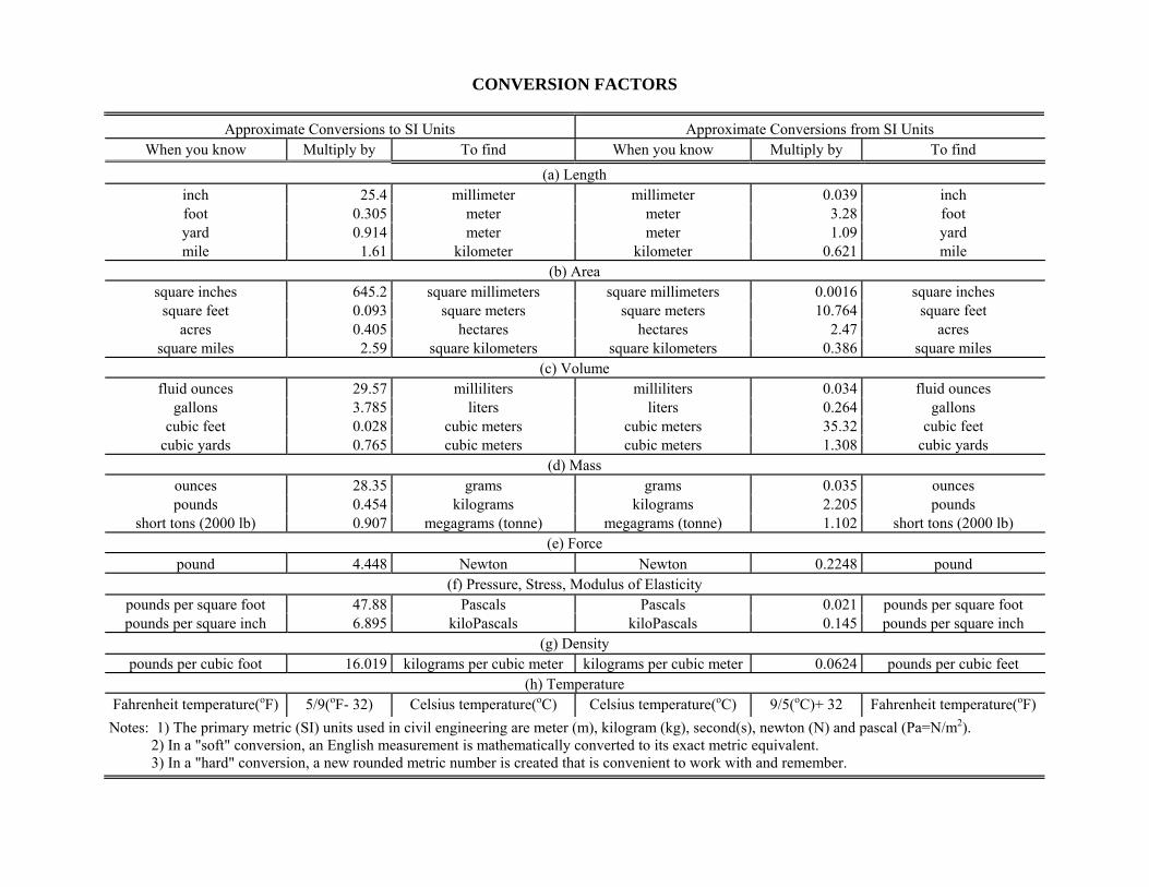
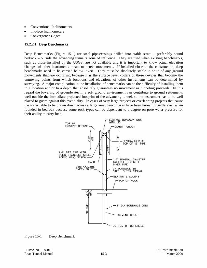
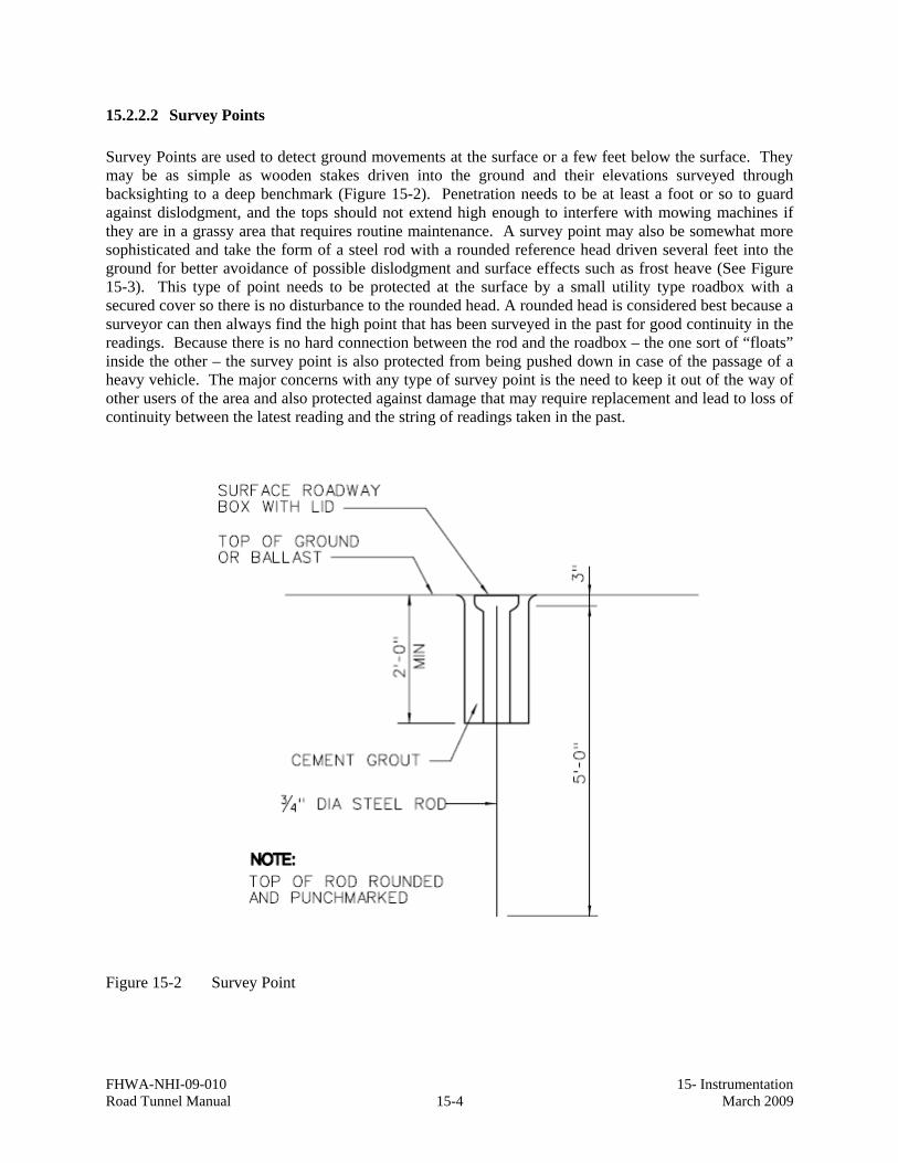
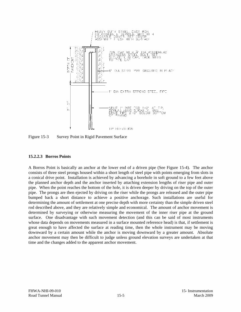
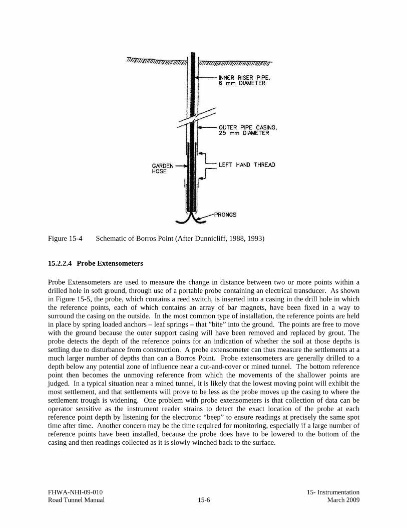
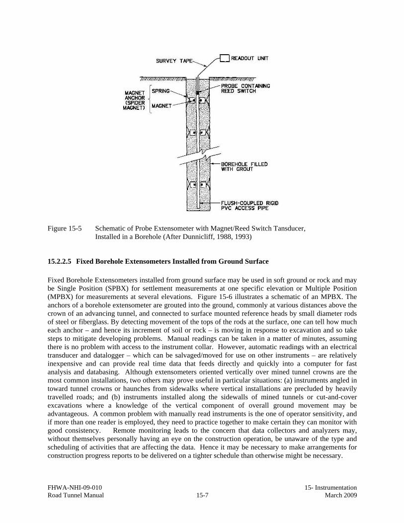
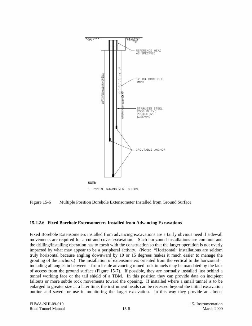
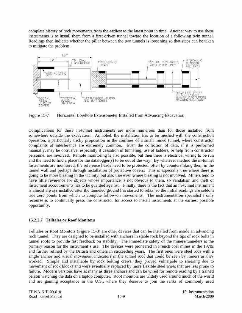
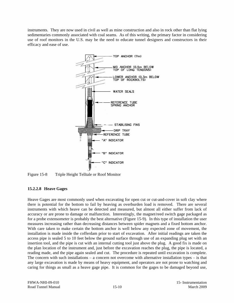
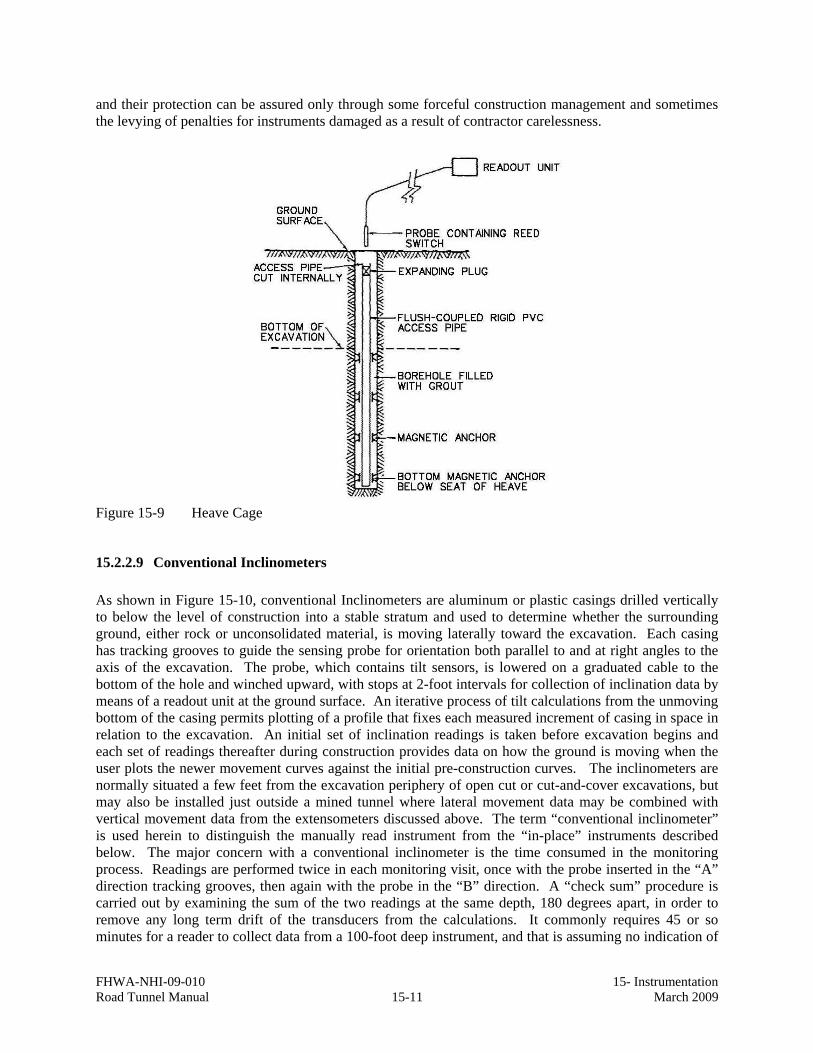
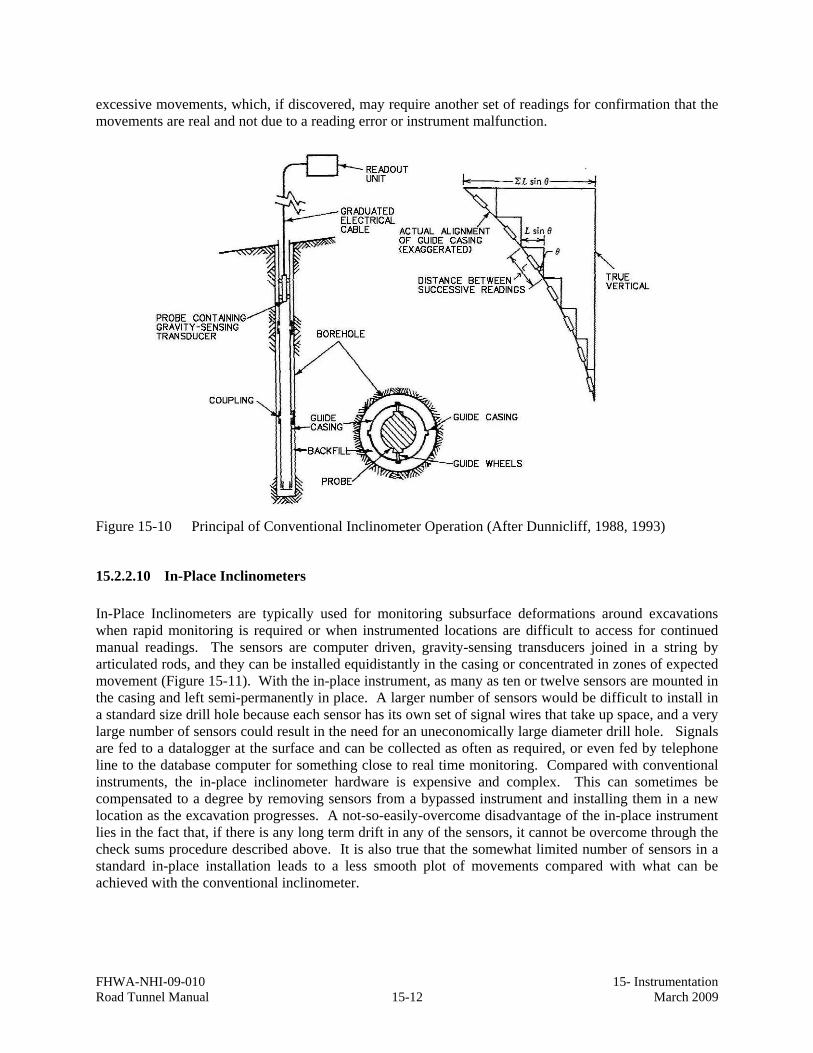
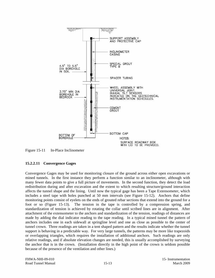
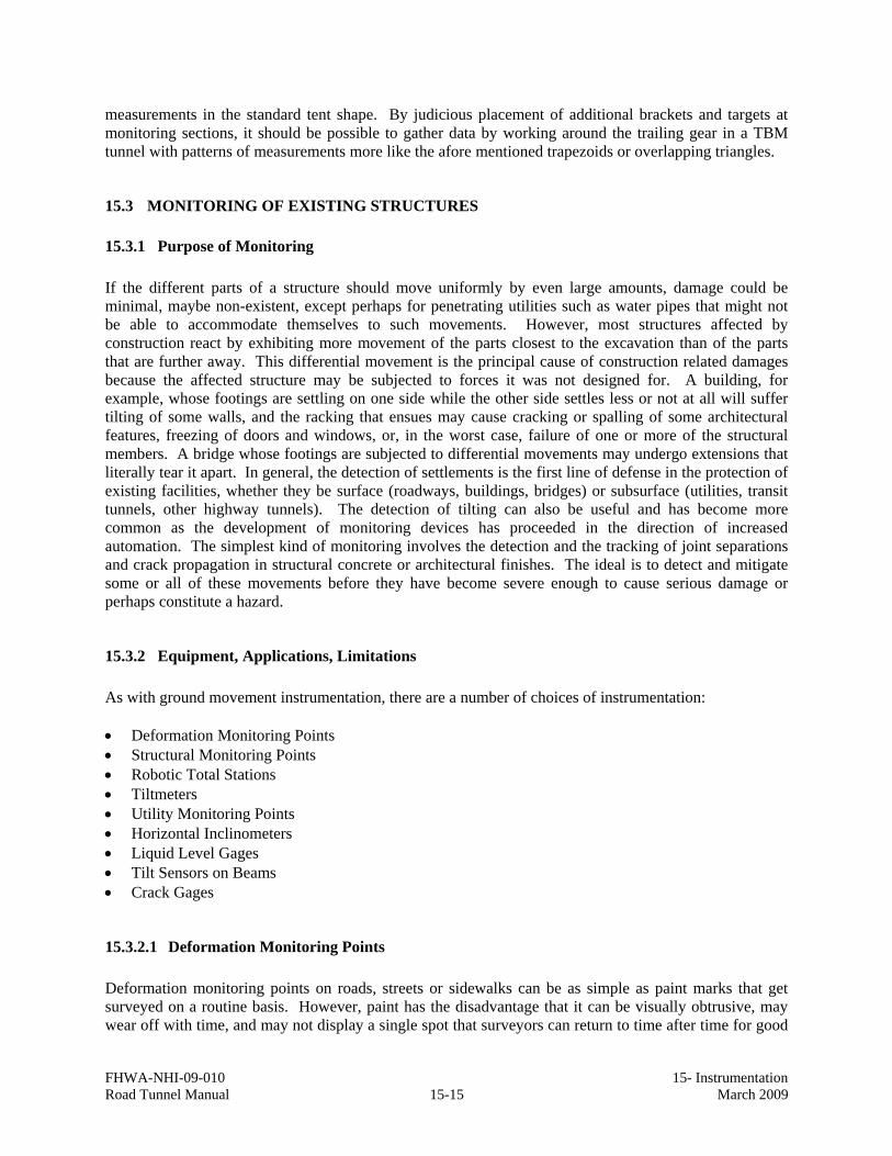
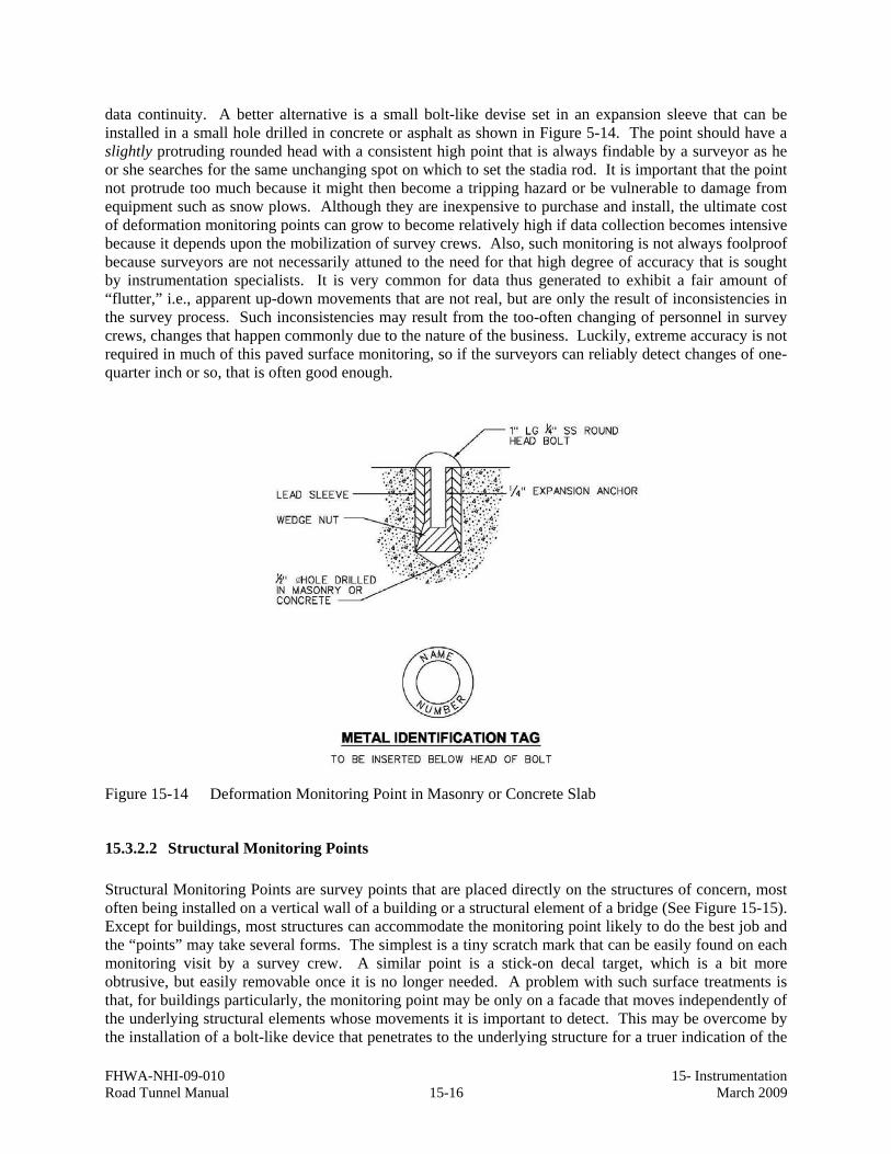
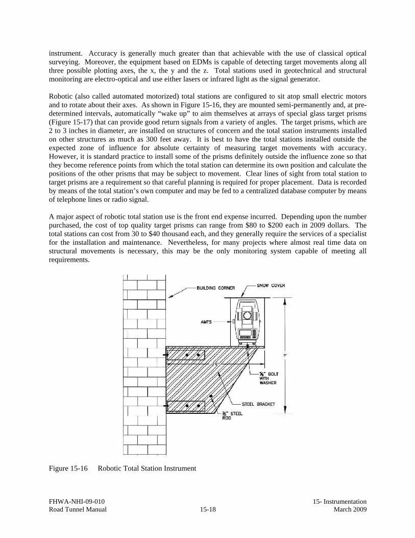
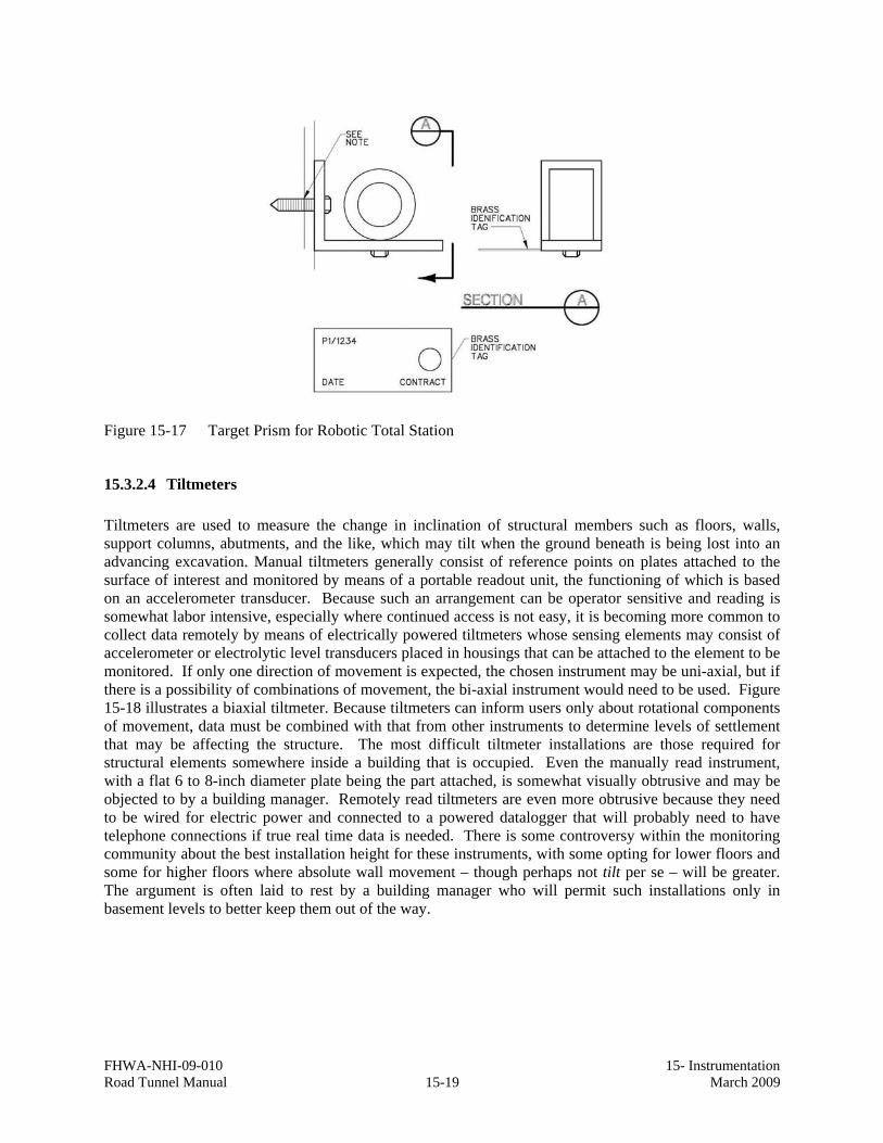
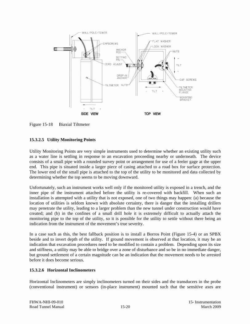
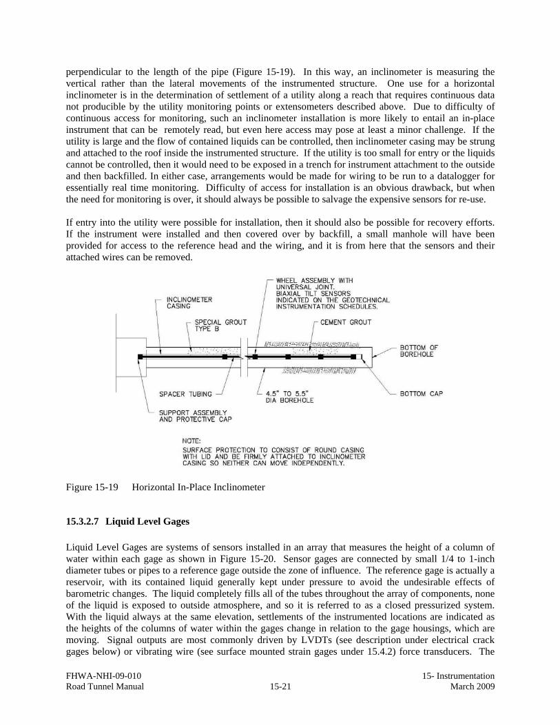
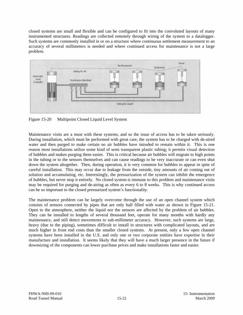
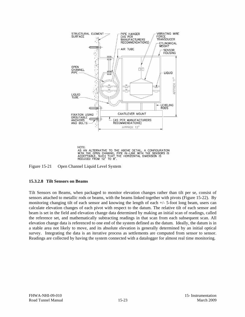
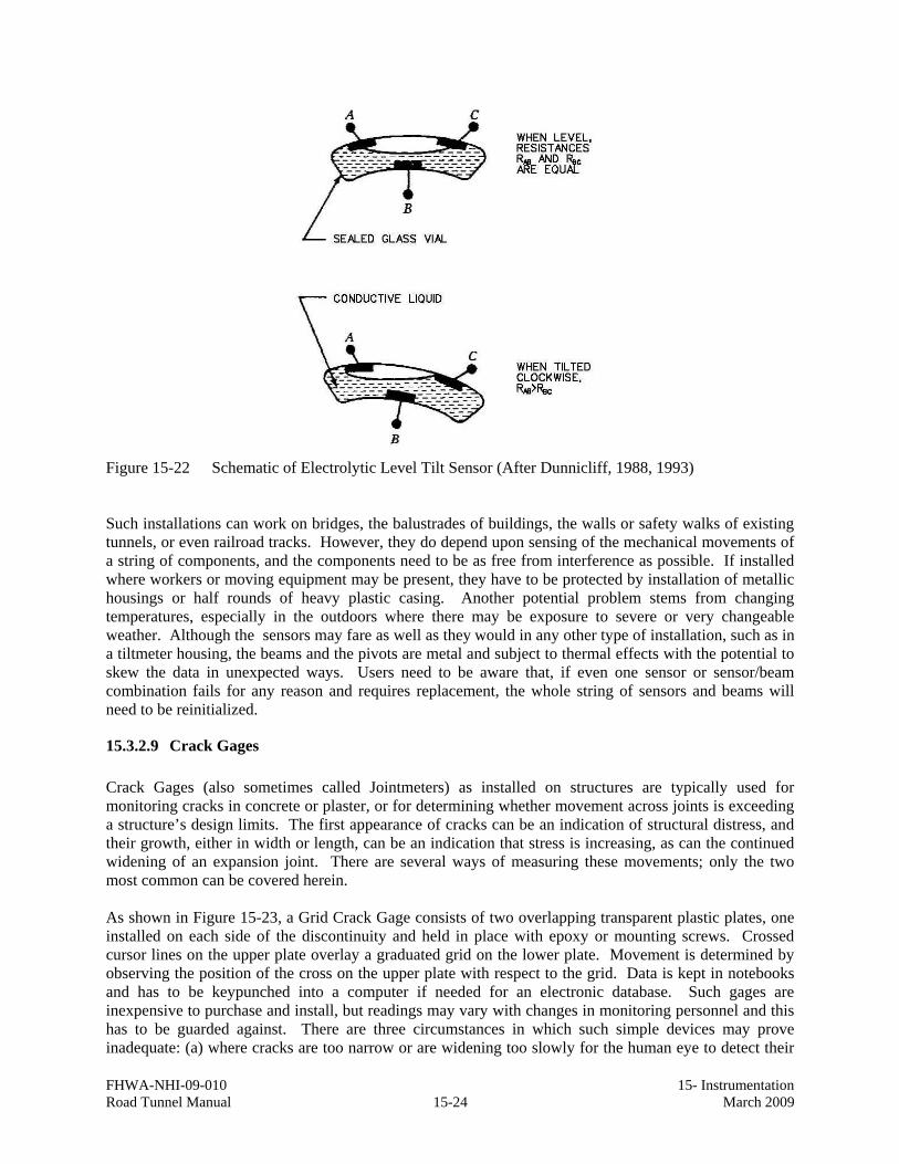
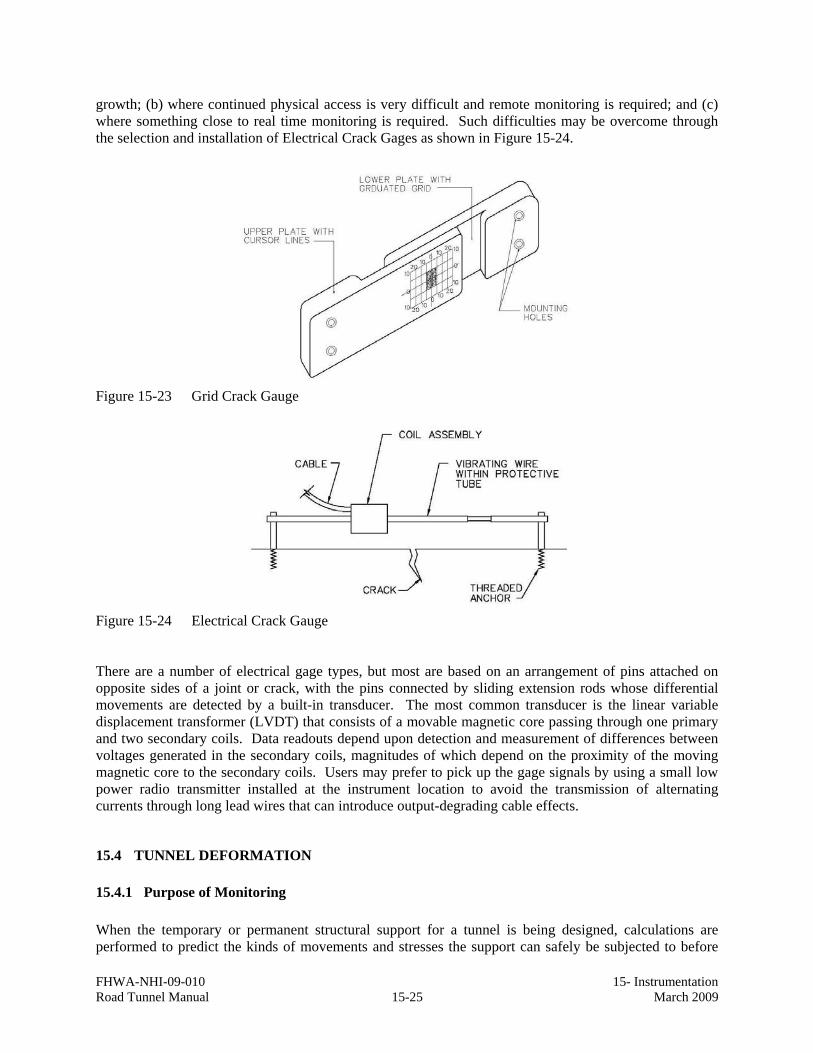
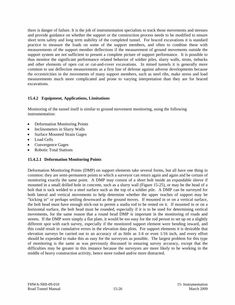
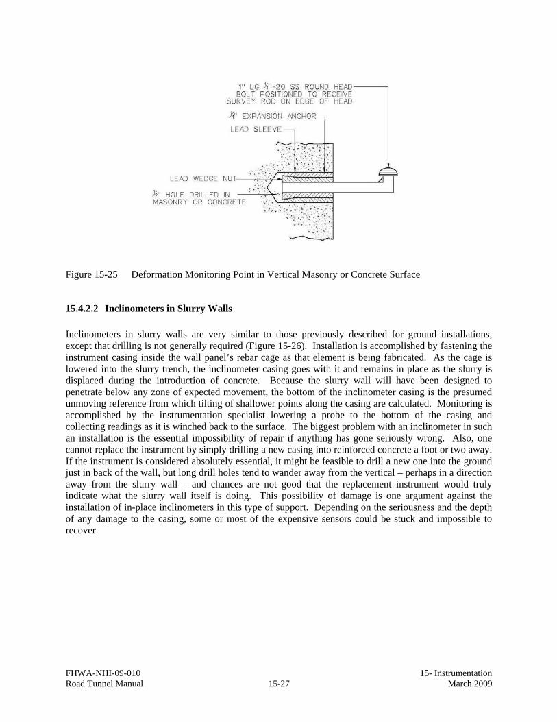
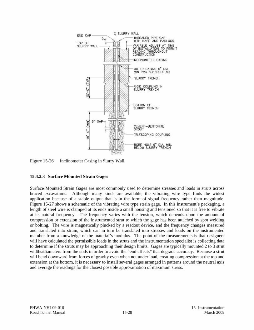
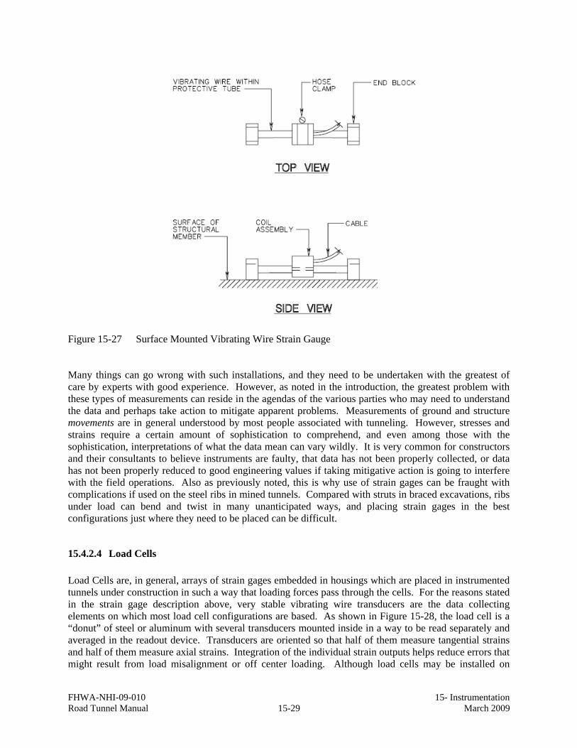
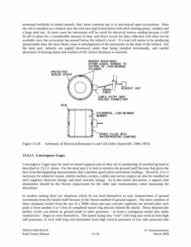
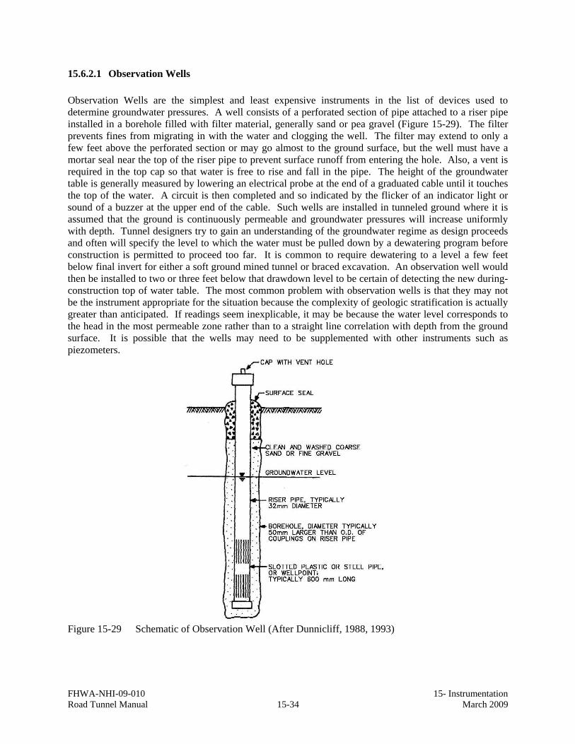
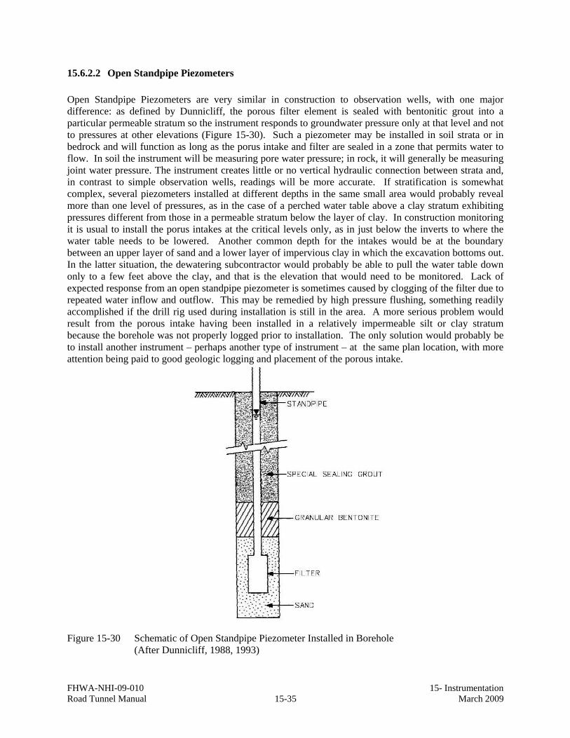
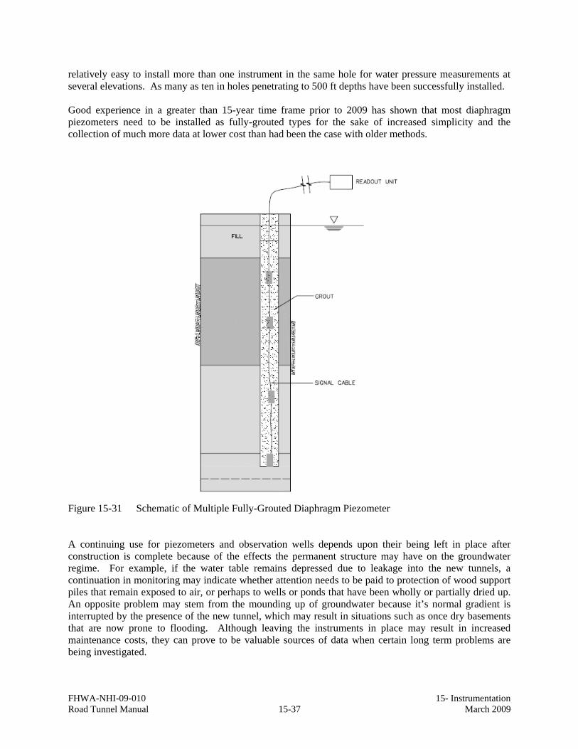