TEST & MEASURING INSTRUMENTS - TradeIndiaimg.tradeindia.com/fm/6199153/product-list.pdf · TEST &...
48
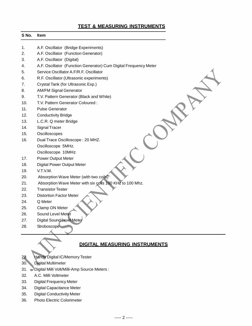
----- 2 ----- TEST & MEASURING INSTRUMENTS S No. Item 1. A.F. Oscillator (Bridge Experiments) 2. A.F. Oscillator (Function Generator) 3. A.F. Oscillator (Digital) 4. A.F. Oscillator (Function Generator) Cum Digital Frequency Meter 5. Service Oscillator A.F/R.F. Oscillator 6. R.F. Oscillator (Ultrasonic experiments) 7. Crystal Tank (for Ultrasonic Exp.) 8. AM/FM Signal Generator 9. T.V. Pattern Generator (Black and White) 10. T.V. Pattern Generator Coloured : 11. Pulse Generator 12. Conductivity Bridge 13. L.C.R. Q meter Bridge 14. Signal Tracer 15. Oscilloscopes 16. Dual Trace Oscilloscope : 20 MHZ. Oscilloscope 5MHz. Oscilloscope 10MHz. 17. Power Output Meter 18. Digital Power Output Meter 19. V.T.V.M. 20. Absorption Wave Meter (with two coils) 21. Absorption Wave Meter with six coils 100 KHz to 100 Mhz. 22. Transistor Tester 23. Distortion Factor Meter 24. Q Meter 25. Clamp ON Meter 26. Sound Level Meter 27. Digital Sound Level Meter 28. Stroboscope DIGITAL MEASURING INSTRUMENTS 29. Handy Digital IC/Memory Tester 30. Digital Multimeter 31. Digital Milli Volt/Milli-Amp Source Meters : 32. A.C. Milli Voltmeter 33. Digital Frequency Meter 34. Digital Capacitance Meter 35. Digital Conductivity Meter 36. Photo Electric Colorimeter
-
Upload
nguyenlien -
Category
Documents
-
view
226 -
download
4
Transcript of TEST & MEASURING INSTRUMENTS - TradeIndiaimg.tradeindia.com/fm/6199153/product-list.pdf · TEST &...
----- 2 -----
TEST & MEASURING INSTRUMENTS
S No. Item
1.
A.F. Oscillator (Bridge Experiments)
2. A.F. Oscillator (Function Generator)
3. A.F. Oscillator (Digital)
4. A.F. Oscillator (Function Generator) Cum Digital Frequency Meter
5. Service Oscillator A.F/R.F. Oscillator
6. R.F. Oscillator (Ultrasonic experiments)
7. Crystal Tank (for Ultrasonic Exp.)
8. AM/FM Signal Generator
9. T.V. Pattern Generator (Black and White)
10. T.V. Pattern Generator Coloured :
11. Pulse Generator
12. Conductivity Bridge
13. L.C.R. Q meter Bridge
14. Signal Tracer
15. Oscilloscopes
16. Dual Trace Oscilloscope : 20 MHZ.
Oscilloscope 5MHz.
Oscilloscope 10MHz.
17. Power Output Meter
18. Digital Power Output Meter
19. V.T.V.M.
20. Absorption Wave Meter (with two coils)
21. Absorption Wave Meter with six coils 100 KHz to 100 Mhz.
22. Transistor Tester
23. Distortion Factor Meter
24. Q Meter
25. Clamp ON Meter
26. Sound Level Meter
27. Digital Sound Level Meter
28. Stroboscope
DIGITAL MEASURING INSTRUMENTS
29. Handy Digital IC/Memory Tester
30. Digital Multimeter
31. Digital Milli Volt/Milli-Amp Source Meters :
32. A.C. Milli Voltmeter
33. Digital Frequency Meter
34. Digital Capacitance Meter
35. Digital Conductivity Meter
36. Photo Electric Colorimeter

----- 3 -----
37.
Digital Mains Frequency Meter :
38. Digital Lux Meter :
39. Digital pH/mV Meter :
40. Digital FLUX METER (Gauss Meter) :
41. Digital L.C.R. Meter :
42. Digital L.C.R. Meter Hand Held
43. Digital Potentiometer
44. Digital R.P.M. Meter
45.
NUCLEAR PHYSICS
G. M. Counter Digital
46. Radio Active Source (in Lead Container)
a. Beta Source
b. Gamma Source
c. Alfa Source
47. Scientillation Counter
48. Radiation survey meter with display(Hand Held GM Counter)
49. Radiation survey meter with buzzer
50.
OPTO ELECTRONIC DEVICES
Photo Electric Cell Mounted on Base
51. Plank's Constant Apparatus
52. App. to determine Inverse Square Law in Photo Cell
53. App. to draw Spectral Azimuthal Angle & Stopping Potential of
given Photo Voltic Cell.
54. LDR Characteristics Apparatus
55. Photoelectric Relay Apparatus
56. LED Characteristics Apparatus
57. Characteristics of OPTO Electronic Devices Kit
58. Photodiode Characteristics Apparatus
59. Photo Transistor Characteristics Apparatus
60. Mercury Vapour Lamp (Hg) for use above Photo Voltaic Cell
61. Solar Cell Mounted
62. Solar Cell Characteristics Apparatus with wooden bench.
63. Plank's Constant Apparatus using Solar Cell
64. Photo Multiplier Tube 931 with Housing
MICROPROCESSORS
65. 8085 Microprocessor Training Kit
Note : We have complete range of microcontroller / microprocessor Kits
e/m APPARATUS
For measuring the ratio of charge to the mass of an electron
66. e/m By Thomson (Bar Magnet Method)
----- 4 -----
67.
e/m by Helical Method (Long Solenoid Method)
68. Millikan's Oil Drop Apparatus WITH POWER SUPPLY.
69. Power Supply for Millikan's Oil Drop App.
70. e/m by Short Solenoid Method (Megnatron Methods)
71 . e/m by Magnetic Focusing Method
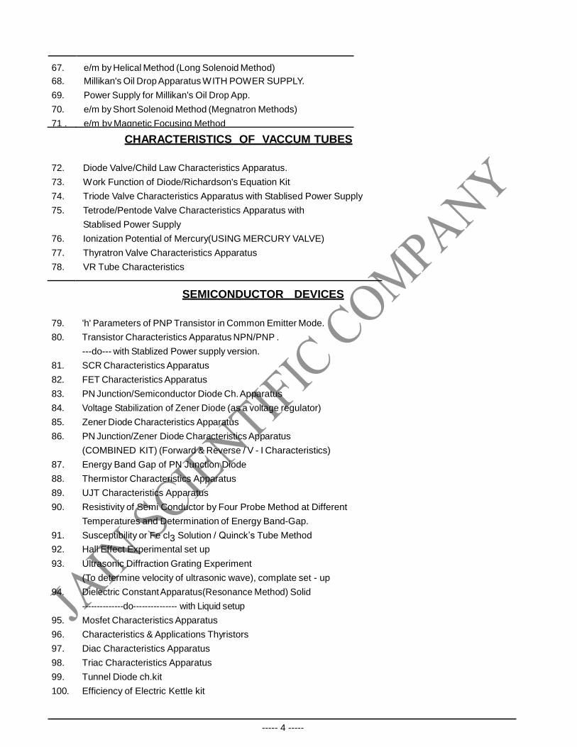
CHARACTERISTICS OF VACCUM TUBES
72. Diode Valve/Child Law Characteristics Apparatus.
73. Work Function of Diode/Richardson's Equation Kit
74. Triode Valve Characteristics Apparatus with Stablised Power Supply
75. Tetrode/Pentode Valve Characteristics Apparatus with
Stablised Power Supply
76. Ionization Potential of Mercury(USING MERCURY VALVE)
77. Thyratron Valve Characteristics Apparatus
78. VR Tube Characteristics
SEMICONDUCTOR DEVICES
79. 'h' Parameters of PNP Transistor in Common Emitter Mode.
80. Transistor Characteristics Apparatus NPN/PNP .
---do--- with Stablized Power supply version.
81. SCR Characteristics Apparatus
82. FET Characteristics Apparatus
83. PN Junction/Semiconductor Diode Ch. Apparatus
84. Voltage Stabilization of Zener Diode (as a voltage regulator)
85. Zener Diode Characteristics Apparatus
86. PN Junction/Zener Diode Characteristics Apparatus
(COMBINED KIT) (Forward & Reverse / V - I Characteristics)
87. Energy Band Gap of PN Junction Diode
88. Thermistor Characteristics Apparatus
89. UJT Characteristics Apparatus
90. Resistivity of Semi Conductor by Four Probe Method at Different
Temperatures and Determination of Energy Band-Gap.
91. Susceptibility or Fe cl3 Solution / Quinck’s Tube Method
92. Hall Effect Experimental set up
93. Ultrasonic Diffraction Grating Experiment
(To determine velocity of ultrasonic wave), complate set - up
94. Dielectric Constant Apparatus(Resonance Method) Solid
--------------do--------------- with Liquid setup
95. Mosfet Characteristics Apparatus
96. Characteristics & Applications Thyristors
97. Diac Characteristics Apparatus
98. Triac Characteristics Apparatus
99. Tunnel Diode ch.kit
100. Efficiency of Electric Kettle kit
----- 5 -----
LASER EXPERIMENT
101. Helium Neon Laser(He.Ne. Laser)2mW with inbuilt power supply
He.Ne. Laser 5mW with inbuilt Power supply
102 Laser (Semiconductor) 5mW.with power supply
Laser Accessories
(a) Low Line Diffraction Grating for Laser wave Length
(b). Young's double Slit
(c). Hand Micrometer
(d). Grating Stand
(e). Laser Filter
(f). Set of 13 (Demo Kit) Single Slit, Taper Slit, Holes A, B, C, D,
Gray Filter, Multiple slit,Circular Opaque spot,Mesh,Multiple Slit 5,
Grid Pattern, Multiple Slit
103 Laser Power Meter.
Note : We have complete range of Lasers & its Accessories. i. e. Laser Diode/He.Ne.
10mW ,25mW Laser googles etc.
104. MICHALSON’S INTERFEROMETER with diode Laser inbuilt
VERIFICATION OF VARIOUS LAWS & CONVERSION OF SIGNAL
105
Measurement of Peak, Average & RMS Value of a AC Signal
106. Resistance in Series & Parallel Apparatus
107. Ohm's Law Apparatus
108 Charging & Discharging of condenser
109. Flashing & Quenching of Neon
110. BH Curve Apparatus (with Different Material)
111. Conversion of Galvanometer into a Voltmeter and Current Meter
112. LCR Resonance Apparatus Series & parallel)
LCR Resonance Apparatus (Series & Parallel) Complete App.
113.. LCR Impedance Circuit
114 RC Circuit (Transient Response)
115. Clipping & Clamping Circuit Apparatus
116. Half Wave/Full Wave /Bridge Rectifier App.
117. Study of STEFAN’S LAW
DEMONSTRATION MODELS
118. Demonstration Television (Coloured)
119. Demonstration Model of Transistor Cassette
Player/Recorder Trainer Kit (Two in One)
120. Demonstration Model for Experiments of MW Radio Circuits
121 Demonstration Cathode Ray Oscilloscope (5MHz CRO)
----- 6 -----
AMPLIFIERS KITS
122. Study of Transistor Amplifier Circuits (C.E.AMPLIFIER)
123 Study the effect of negative feed back of transistor amplifier
124. Push Pull Amplifier :
125 FET Common Source Amplifier
126. Biasing of Transistor (BJT)
127. R.C. Coupled Amplifier (Two Stage)
128. RC Coupled with Inbuilt Two AC Millivoltmeter (VTVM)
VERIFICATION OF NETWORK THEOREMS
129. Verification of Network Theorems
130. Verification of Super Position Theorem
131. Verification of Norton’s Theorem
132. Verification of Thevinin’s Theorem
133. Verification of Norton's & Thevinin's Theorems.
134. Verification of Reciprocity Theorem
135. Verification of Maximum Power Transfer Theorem in DC Circuits
CHARACTERISTICS OPERATIONAL AMPLIFIERS
136. Operational Amplifier as Inverting & Non Inverting Amplifier
137. Study of Operational Amplifier
138. Study of Characteristics of Operational Amplifier
139. Operational Amplifier kit (BREAD BOARD TYPE)
140. Study Operational Amplifier as Adder, Subtractor, Integrator and
Differentiator
141. Study of Operational Amplifier as Differentiator & Integrator.
142. Study of Operational Amplifier as Schmitt Trigger.
143. Study of Operational Amplifier as Sine to Square Wave Convertor.
144. Study of Operational Amplifier as Square to Triangular & Trinagular
145. Study of Operational Amplifier as Clipping and Clamping Circuit
146. Study of Operational Amplifier as Voltage Comparator
147. Study of Operational Amplifier as V to I & I to V Convertor
148. Study of Operational Amplifier as Voltage and Current
Feed Back Amplifier
149. Study of Instrumentation Amplifier
150. Study of Logarithmic Amplifier
STUDY OF MULTIVIBRATORS
All the Multivibrators Kits are with DC Power Supply, Circuit Diagram Printed
& Components mounted on front Panel. Kits require CRO as Accessories.
151. Monostable Multivibrator using IC 555
152 Application of IC 555

----- 7 -----
153. Astable Multivibrator using IC 555
154. Astable Multivibrator using Transistors.
155 Bistable Multivibrator using IC 555.
156. Bistable Multivibrator using Transistors.
157. Monostable & Free Running Multivibrators using IC 555.
158. Monostable & Free Running Multivibrators using Transistors.
159. Astable, Monostable & Bistable Multivibrator using Transistor
OSCILLATORS
160. Hartley Oscillator
Hartley Oscillator with inbuilt DIGITAL Frequency Counter
161. Colpitt Oscillator
162. Phase Shift Oscillator
163. Wein Bridge Oscillator using Operational Amplifier IC 741
DIGITAL ELECTRONIC EXPERIMENTS
(Computer Principles)
164. Logic Gates Experiment Kit
Logic Gates Experiment with separate I.Cs (each Gate)
165. Verification of Booleon Identities & Demorgan's Theorems
166. Verification of Logic Gates & Demorgan's Theorems using
TTL logic Gates (For All demorgan’s experiments)
167. Verification of truth tables of Logic gates using NAND Gate
168. Study of 4 Bit Adder and Subtractor
169. Digital Kit Verify Adders & Subtractors , Half / Full Adder
170. Digital Trainer to Verify Half Adder using OR, EX-OR & AND gates.
171. Digital Trainer to Verify Half Subtractor using OR, EX-OR & AND gates.
172. Digital Trainer to Verify Full Adder using OR, EX-OR & AND gates.
173. Digital Trainer to Verify Full Subtractor using OR, EX-OR & AND gates.
174. Digital Trainer to Verify Adders & Subtractor using NAND gates,
175. Study of 4 Bit Binary to Gray Code Convertor
176 Study of 4 Bit Ripple Counter (Forward & Reverse)
177. Study of 4 Bit BCD Counter/Decimal to Binary Encoder using IC 7490
178. Study of 4 Bit BCD Counter/Decimal to Binary Encoder using
NAND gates
179.. To study truth table of 4 bit Up & Down counter using IC 74193
180. Study of Left, Right & Programmable Shift Register
181. BCD to Decimal Decoder Using IC. 7492
182. Study of Encoder & Decoder Circuits (Decimal to BCD Encoder &
BCD to 7-segment Decoder)
183. Digital Trainer to study & verify truth tables of Flip Flops
184 Digital Trainer to study 'RS' Type, 'JK' & 'T' Type flip-flop
185. Study & Verify Truth tables of 'RS'&'D' Type flip flop using NANDgates

----- 8 -----
186.
Study & Verify Truth tables of 'JK' & 'JK Master Slave' flip flop.
187. Study 8-1 line (four input & one output) Multiplexer using IC 74153
188. Study of 2-1 Multiplexer using AND, OR & NOT gates.
189. Study 16-1(Sixteen input & one output)Multiplexer using IC-74150
190. Study of One input/.Four output Demultiplexer using IC 74155
191. Study 4-16(One input/Sixteen output)Demultiplexer using IC 74154
192. Study of RAM (Random Access Memory) Circuit
193. Analog/Digital Trainer (Bread Board Type)
194. Logic Gate Circuit Trainer/Digital Computer-II[Bread Board Model]
195. Logic Gate Circuit Trainer using TTL IC's
196. To Verify Switch Debouncer
197. To Measure the Clock Pulse I.C. 7400
198. Analog to Digital (A/D) Converter
199. Digital to Analog (D/A) Convertor using R-2R Network
200. Digital to Analog (D/A) Convertor using Weighted Register Network
TRAINING KITS FOR COMMUNICATION LAB
201.
Study of Transmitter & Receiver using Fiber Optics Cable
202. Study of Amplitude Modulation & Demodulation
203. Study of Frequency Modulation & Demodulation
204. Study of Frequency Modulation
205. Study of Pulse Amplitude Modulation & Demodulation
206. Study of Pulse Position Modulation & Demodulation
207. Study of Pulse Position & Pulse Width Modulation
208. Study of Phase Locked Loop (PLL) Circuit using IC
POWER SUPPLIES & TRANSFORMERS
209.
Power Supplies for Diode Valve Experiment
210. Power Supply For Electrophoresis VARIPACK
211. Power Supply for Triode Valve Experiment
212. Power Supply for Electrophoresis With Analogue Meter
Power Supply for Electrophoresis With Digital Meters
213. Power Supply for Tetrode/Pentode Valve
214. Fixed Voltage I.C. Regulated Power Supplies 500 mA
Fixed Voltage I.C. Regulated Power Supplies 1 Amp.
215. Fixed Voltage I.C. Regulated Dual Power Supplies 500 mA
216. Regulated Power Supply, Fixed ± 5v & ± 12v.
217. Digital Regulated Power Supply.
218. High Voltage Power Supply.
219. Dual Power Supply ±0-30 Volt 1 Amp.
220. Power Supply 0-30 Volt 2 Amp.
221. Dual Power Supply ±15 Volt 500mA.
222. Power Supply 0-30 Volts 3Amp.
223. Battery Chargers

----- 9 -----
224. Battery Eliminators cum
Step-Down Transformer
225. Transformers FOR SODIUM LAMP 35 WATTS
----------------------DO ------------------- 55 WATTS
226. Dimmerstate/ Variac/Auto Transformer
SWITCHBOARD PANEL AMMETERS AND VOLTMETERS
227.
Micro Ammeters :
228. Ammeters :
229. Voltmeters :
230. Galvanometers :
AC RECTIFIER TYPE VOLTMETER
(Moving Coil Type)
231. VOLTMETER & AMP. METER
232. Digital Panel Meters
233. EXTERNAL SHUNTS WITH 50 mV or 75 mV Drop
234. Power Factor Meter
235. Portable Meter
236. Cell Tester
237. High Meg Resistance Box
238. Demonstration Joint Meter
239. Power Factor Meter
240. Frequency Meter
241. D’ Arsonal Galvanometer
242. Ballistic Galvanometer Reflecting
243. Spot Reflecting Galvanometer
244. Insulation Tester
----- 10 -----
Resistance Max. Current Accuracy
(in ohms) (in Amperes) (in %)
A 0.001 10 0.05
B 0.01 10 0.05
C 01 5 0.05
500 0-100M. Ohms ±5%.
1000 0-200M. Ohms ±5%.
245. Ohms Meter
0-100 Ohms, 0-250 Ohms
0-500 Ohms, 0-1000 Ohms
246. High Voltage Insulation Break Down Tester
247. Low Ohms Meter
DECADE BOX
248. Decade Inductance Box
Single Dial.1 H to 1 H.
2 Dials.01, H to 1.1 H.
3 Dials.01 H to 11.1 H.
4 Dials.001 H to 11.1 H.
249.
Fixed inductance 100 mH, 1H, 10H, 20H.
Decade Capacitance Box
Single Dial.1 mfd to 1 mfd.
2 Dials.01 mfed to 1.1 mfd.
3 Dials.001 mfd to 1.11 mfd.
4 Dials.001 mfd to 11.11 mfd.
250.
Fixed capacitance (in Bekalite Box)
Decade Resistance Box
Single Dial1K Ohms to 10K Ohm
2 Dials10 Ohms to 1000 Ohms.
3 Dials1 Ohms to 1000 Ohms.
4 Dials1 Ohms to 10000 Ohms.
Fixed Resistance Box (in Bekalite Box)
251. Slide Wire Rheostats
252. Resistance Coil.
Any one single range from 0.1O to 500
253. Standard Resistance
Standard resistances of 0.1, 0.01 and 0.001 ohm are provided with 4 terminals
while those of 1, 10, 100, 1000 ohms are provided with 2 terminals only.

----- 11 -----
D 1 3 0.01
E 10 1 0.005
F 100 0.5 0.005
G 1000 0.2 0.005
254. Dial Type Resistance Boxes
Post Office Box Dial Pattern
255. Post Office Box 3-Dials (Constantan Coil)
256. Post Office Box 4-Dials (Manganin Coil)
257. Super Sensitive Galvanometer
258. Different type of 4 Arms Bridges (with Fix frequency Oscillator & Headphone)
(1) Anderson Bridge
(2) Weins Bridge
(3) Desauty Bridge
(4) Schering Bridge
(5) Maxwell Bridge
(6) Hey's Bridge
(7) Owen's Bridge
259 WHEATSTONE’S BRIDGE
M O I S T U R E M E T E R P R I C E L I S T
1. Universal Moisture Meter Digital.
Universal Moisture Meter Digital (Thumbwheel model).
2. Digital Moisture Meter.
Digital Moisture Meter (Thumwheel model).
3. Infrared Moisture Balance.
4. Digital Infrared Moisture System.
5. Digital Seed Counter.
Digital Seed Counter (Microcontroller based).
6. Soil Meter Analogue.
7. Digital Soil Meter.
8. Moisture Meter For Wood.
9. Digital Moisture Meter For Wood.
----- 12 -----
CONTACT: JAIN SCIENTIFIC COMPNAY 141,CANARA APART. , SECTOR-13, ROHINI, DELHI-110085 EMAIL- [email protected], [email protected] WEBSITE- jainscientific.com RAHUL JAIN :09999576452 ASHISH SHARMA :08802449320
1
Website: www.jainscientific.com
METROLOGY INSTRUMENTS
01. Precision Autocollimator
Single axis
Dual axes
Common Features of Precision Auto –Collimator:
Objective focal length : 500 mm
Objective clear aperture : 45 mm
Eyepiece magnification : 10X
Telescope specification : 20X
Range of measurements : ±20′
Working distance up to 5 meters. For full range of measurement : ±16′
Working distance up to 10 meters. For full range of measurement : ±8′
Number of division on micrometer : 60
Least count of micrometer : 2″
Precision of setting : 1″
Accuracy over full range of measurement : 2″ * Reflecting Mirror with base
Specification:
Material: Optical glass BSC / BK-7
Front surface coated mirror. Coating material: Al. with protective coat of SiO.
Dia. 50 mm; Thickness: 10 mm; Clear aperture: 45 mm.
Front surface optically flat; Surface flatness: λ/4; other face: fine ground. Foot span of base: 110 mm; Width: 62 mm . Bottom and sides are optically ground.
Mirror is mounted on the base at 90° ±2′.
2
02. Precision Angle Dekkor (Dual axes)
Specification:
Direct reading on knob : 3″ (Least count of Angle Dekkor)
Maximum reading on graticule : ±50′X & ±50′Y
Graduation on graticule :1′ each division
Accuracy over 1′ range : 6″
Accuracy over full range : 30″ Measurement axis : Dual
Range of measurement : ±50′X & ±50′Y
Magnification : 16X
Field of view : 100′ Clear
aperture : 26 mm Max.
working distance : 3.5 meters
Illumination : 2W, 6V
* Reflecting Mirror with base
Specification:
Material: Optical glass BSC / BK-7
Front surface coated mirror. Coating material: Al. with protective coat of SiO
Dia. 50 mm; Thickness: 10 mm; Clear aperture: 45 mm
Front surface optically flat; Surface flatness: λ/4; other face: fine ground
Foot span of base: 65 mm; Width: 62 mm
Bottom and sides are optically ground.
Mirror is mounted on the base at 90° ±2′
Optional Accessories for Auto-Collimator and Angle Dekkor: (i) Glass Cube (Material: Optical glass BSC/BK-7)
Specification:
Size: 40 mm x 40 mm x 40 mm
Surface flatness of all the faced faces: λ/4
Angular accuracy between faces 90° ±5″. Top and bottom are fine ground.
(ii) Cube Corner Prism (Material: Optical glass BSC / BK-7 Specification:
Dia of refracting face: 38 mm; Height: 28.8 mm
Surface flatness of polished face: λ/4 Uncoated.
Deviation: 180° ±2″ (iii) Penta Prism (Material: Optical glass BSC / BK-7)
Optical face at 90°: 40 mm x 40 mm
Surface flatness of polished face: λ/4; accuracy at 90° ±10″ (iv) Right Angle Prism (Material: Optical glass BSC / BK-7)
Optical face: 40 mm x 40 mm
Optical faces are flat to λ/4; Angle accuracy at 90° ±10″
(v) Plane-Parallel (Material: Optical glass BSC / BK-7)
Specification:
Dia.: 50 mm; Thickness: 12 mm approx.
Surface figure, i.e., surface flatness of both faces: λ/10
Out ness from parallelism between faces less than 5″

3
03. (a) Profile Projector
For accurate magnification, maximum luminosity, great contrast, uniform
resolution to the edge of the screen, freedom from distortion of the image. These
are the prominent features of profile projector. It is supplied with standard lenses
with magnification 25X and 50X for contour projection. The maximum visible
part of the object on the screen is 112 mm and 56 mm respectively. The screen
size is 330mmx380mm. The maximum diameter and length of work
accommodated on the stage are 40 mm and 150 mm respectively. It is having
wooden storing cabinet with lock and key for safe custody of lenses etc. The
height and weight of the instrument is approx. 1448 mm and 68 Kg.
(b) Senior Profile Projector
All the specifications are same as mentioned above but having micrometer
measuring system.
(c) Profile Projector
It is a bench type profile projector suitable for all types of measurements and
inspections at industries and institutions. Its multi-layer coated projection lenses
provide high transmission and optimum contrast suitable for contour and surface
in dimensional measurements and surface inspections. Its unique rigid pedestal
system facilities vibration frees handling of components. Wide choice of
accessories enhances the scope of applications in various fields.
It incorporates both Epi and Disscopic illuminators designed on halogen bulb
system to ensure brilliant projection of 300 mm dia fine ground glass screen
rotatable through 360º with vernier reading to 1 minute of an arc. The screen has
cross and detachable clips to hold comparator charts. Its precision micrometer
measuring stage is fitted with rotary measuring stage is mounted on the table,
circular graduated scale divided into 360º in steps of 1° with vernier reading to 6′
on both sides. It operates on ball bearing guides fine micrometer reading to 0.01mm. Lifelong smooth movement is assured by the incorporation of hard steel rolling balls both in longitudinal and transverse slides. The basic instrument is supplied with 10X, a multi element coated projection lens. The projection accuracy ±0.1% in case of contour and ±0.15% in case of surface is provided. Specification: Magnification: 10X; Field of view: 30 mm
Working distance: Contour – 65 mm; Surface – 22 mm
Illumination:
Contour and Surface illuminator 24V 150W halogen brightness adjustable
through solid-state variable control knobs power supply 220V/50Hz.
Cooling: Built-in noiseless and vibration free fan motor
Cross Travel Stage: Size: 150 mm x 150 mm. Table travel up to 50 mm x 50 mm
with the use of Gauge blocks.
Stage glass – dia 70 mm
Optional Accessories for Profile Projector:
(i) Center Holding Device with angular movement up to 10º on either side for
checking angular measurement.
(ii) ‘V’ Block
Set of two numbers with clamp of size 24 mm x 16 mm.
(iii) ‘VEE’ Support
4
With spring clamps for inspection of parts without centers or counter bores.
(iv) 10X magnification for ‘C’
(v) Optional magnification: 20Xor25Xor50X for ‘C’
(vi) Digital micrometer – L.C.: 0.001 mm for ‘C’
(vii) DRO system with micrometer for ‘C’
04. Tool Maker’s Microscope. Model 900
It is an ideal measuring instrument for simplifying inspection and precision
measurement of diameter, forming tool, gauges as well as template checking of thread
and angles.
Standard Specification :
Total magnification : 30X
Objective : 2X
Eyepiece : 15X
Working distance : 65 mm
Field of view : 6 mm
Observation Tube: Monocular inclined at 30° stand. Large and heavy base provides extra overall rigidity to the instrument. Measuring Stage: 150 mm x 150 mm assembled on ball bearing guides to provide accurate and smooth travel up to 50 mm in each direction with the use of gauge blocks having micro-head standard 0-25 mm, least count 0.01 mm.
ROTARY STAGE: Circular stage is fitted on measuring stage, graduated into 360°
with vernier and lock.
Eye Piece Protractor: Graduated in 360° with adjustable vernier reading to 6′ is coupled with monocular ocular tube for smooth angle measurement. Illumination: Sub-stage lamp provides transmitted light from a bottom source providing collimated green filter halogen light. Oblique illuminator with adjustable inclination for surface illumination of sample with relief structure is also provided. Three separate knobs for different illumination are provided with variable light control on the front panel.
05. Tool Maker’s Microscope. Model -500 It is an ideal measuring instrument for simplifying inspection and precision
measurement of diameter, forming tool, gauges as well as template checking of
thread and angles.
Technical Specifications:
Eyepieces: WF10X (with cross) H10X (with micrometer) & H15X
Objectives: 1X – 3X – 5X
Field of View: 10 mm – 3.5 mm – 2 mm
Magnifications: 10X – 15X – 30X – 45X – 50X and 75X
Measuring Stage: 125 mm x 125 mm with interchangeable inter mediate table to
receive different optional accessories. Equipped with micrometer head 0-25 mm
reading 0.01 mm, life long smooth movement is assured by the incorporation of hard
steel rolling balls both in longitudinal and transverse slides. Rotary measuring stage
dia 130 mm is mounted on the table with 55 mm glass aperture, circular graduated
scale is divided into 360° with both side vernier reading 5′.
Observation Tube: Monocular inclined at 45° fitted with Gonio-metric head
graduated 360°.
Illuminations: Two possible range of illuminating systems are provided with standard equipments to meet every application, operated through 6V solid-state variable light
control built-in transformer.

5
Sub-stage transmitted light from a bottom source providing collimated green filtered
halogen light for viewing contours and transparent objects.
Surface incident illuminator for high power examination of opaque objects.
Optional Accessories for Tool Maker’s Microscope :
(i) Centre Holding Device :With angular movement up to 10º on either side for
checking angular measurement.
(ii) ‘V’ Block
Set of two numbers with clamp of size 24 mm x 16 mm.
(iii) ‘VEE’ Support
With spring clamps for inspection of parts without centers or counter bores.
(iv) Projection Attachment – It is comprising of a projection screen dia. 90 mm,
to be placed on the viewing eyepiece, inclined at 30° for getting a sharp
focused image on the projection screen ready for measurement with a high intensity 6V/20W halogen illumination system
Accessories for Model -500 :
Twin Spot Light/Illumination–with adjustable inclination for surface lighting of
samples.
Depthoscope Attachment – It can be provided with the microscope. It is useful for
depth measurement by optical means without physical contact with the specimen with
the specimen. Dial gauge mechanism is coupled with the fine focus control of the
microscope.
Projection Attachment – It is comprising of a projection screen dia. 100 mm to be
placed directly at the place of vertical lamp. Screen at 90° having built-in eyepiece to
give a sharp focused projected image, for simultaneous observation through eyepiece
and on projection screen.
06. Fizeau Test Window / Source of monochromatic light namely Sodium vapour lamp
(35 watt) enclosed in a box (10″ x 10″ x 20″ approx.) with choke to run the sodium
lamp, along-with standard / master optical flat (Dia.: 10 mm, 25 mm, surface flatness
λ/10, parallelism within 10″)
SOURCE OF LIGHT 07. He-Ne Laser (Red) with power supply, wavelength: 633 nm
Output power: 1.0 mW to 10 mW
Specification of laser:
Type : Helium-Neon; hermetically sealed; hemispherical resonator
Wavelength : 632.8 nm; intense red light
Polarization : Randomly polarized
Beam divergence : 1.5 milli radian
Beam parameter : TEMoo
Current : 5.0 mA; Current limit: 5.2 mA Voltage : 1100V ± 50V; Discharge voltage: 6 kV approx.
Discharge time : < 1 second
Life span : > 5000 hrs., typical 20,000 hrs.
Specification of power supply:
Input voltage : 220V ± 5%; 50 Hz
Input power : 15 watt approx.
Discharge voltage : Till 8 kV approx.
08. Diode laser (Red) with power pack, wavelength: 650 nm

6
Output power from 3.0 mW to 50.0 mW
09. Diode laser (Green) with power pack, wavelength: 535 nm
Output power from 5.0 mW to 50.0 mW
10. Sodium vapour lamp with choke and enclosure (Enclosure is provided with 3-slots of
6″ x ½″ at three sides of the rectangular wooden box) Output power: 35 watt and 55 watt
11. Mercury vapour lamp (High pressure) with choke and enclosure (Enclosure is
provided with 3-slots of 6″ x ½″ at three sides of the rectangular wooden box)
Output power: 85 watt and 125 watt
12. Mercury vapour lamp (Low pressure) with power supply, clamp to hold it and stand
Output power: 170 watt
LASER HARDWARE COMPONENTS 13. (i) Translation stage (1-axes, 2-axes, 3-axes)
Total travel: 25 mm; Top size: 70 mm x 70 mm; Least count: 0.01 mm
Drive in x and y direction by micrometer and z by gear
(ii) Translation stage (x, y and z stages with angular rotation for z)
Rotation: 360°; least count: 0.01° Drive in x and y direction by micrometer and z by gear and tangential torque using micrometer for rotation.
14. Rotation stages, Dia.: 110 mm
Graduated in 360°; least count: 6′; Fine rotation by gear Load carrying capacity: 10 kg.
15. Collimator. Clear aperture: 25 mm to 75 mm
16. Spatial filter assembly
17. Beam steering device
It consists of 2 nos. of orthogonal mirror mounts with casing to hold the front surface
coated mirrors.
Dia. 50 mm; Thickness: 10-12 mm
The mirrors are being hold at 45º, Total height of beam steering device: 350 mm
Heavy base is provided for stability.
Variable distance for the mirror in vertical plane
Pillar dia: ~ 50 mm ; Base plate dia: 150 mm; Hole matrix: M6
18. Kinematics mounts for orthogonal tilt arrangement for front surface coated mirrors,
beam splitters and lenses
19. Vibration Isolation Table / Honeycomb breadboard
Top and bottom are made of ferromagnetic material.
Sheet thickness: ~ 5 mm; Hole matrix: 25 mm x 25 mm with M6 tapped hole
Top is mechanically flat with smooth finish having mate grey color
Available in different sizes and thickness
OPTICAL COMPONENTS 20. (a) Prisms: Equilateral prism (µ - 1.51, 1.58, 1.61, 1.65 and 1.71)
Optical face: 25 mm x 25 mm, 32 mm x 32 mm, 38 mm x 38 mm
Surface flatness: λ/2 to λ/4 of optically worked polished faces
Angle accuracy at 60° ±10′
1010
(b) Right Angle Prism available in various sizes
Surface flatness of optically worked polished faces: λ/2 to λ/10
Angle accuracy at 90° ±5″
(c) Constant Deviation Prism (µ - 1.65 and 1.71); Height: 25 mm to 40 mm
Longest arm: 45 mm to 85 mm
Three faces are optically worked to surface finish λ/4 to λ/10
Angle accuracy at 4 corners: better than 10′
(d) Penta Prism / Optical Square (Material: Optical glass BSC / BK-7)
Optical face at 90°: 40 mm x 40 mm
Surface flatness of polished face: λ/4; Accuracy at 90° ±10″ Available in various sizes.
(e) Corner cube Prism from 10.0mm to 25.0mm Aperture.
Angle accuracy at vertex ±2″
Outness from parallelism: ±5″ between incoming and outgoing beam.
(f) Narrow Angle Prisms & Wedges are available in various sizes as per requirement
(g) Bi-prism, size: 40 mm x 32 mm and 50 mm x 40mm; Angle at vertex: 188.5° ±10′
(h) Calcite Prism, equilateral with optic axis parallel to refracting edge or base of
sizes: 15mm x 15mm; 18mm x 18mm; 25mm x 25mm.
21. (a) Optical Flats (Flatness λ/2 to λ/10): Dia.: from 10 mm to 100 mm at various
Thickness and flatness.
(b) Front Surface Coated Mirror (Flatness: λ to λ/10) of dia. 10 mm to 150 mm (c) Plane-Parallel, Dia.: 10 mm to 100 mm
Out ness of parallelism less than 5″. (d)
Spherical Mirror (Concave / Convex)
Dia.: 25 mm to 200 mm; Focal length: 50 mm to 1000 mm (e) Parabolic Mirror (On-axes / Off-axes))
Dia.: 100 mm to 150 mm; Focal length: 200 mm to 1000 mm
22. Plane Transmission and Reflection type diffraction grating
600 lines per mm, 300 lines per mm, 200 lines per mm and 100 lines per mm
23. Optical Machines- Glass Slitting/ Cutting Machine, Heavy duty Polishing Machine,
Pedal Polishing Machine, Single Spindle Rougher, Roughing Machine, Single
Spindle & Grinding Machine, Trappening Machine, Centering/ edging Machine,
Curve Generation Machine, Lens Making Machine etc.
GENERAL ITEMS 24. Indicating unit/Power meter to the measure the power of laser beam
Measuring range: microwatt to 20 milli watt
25. Fabry-Perot Etalon. Glass plate dia.: 35 mm (semi reflecting); Clear aperture: 25 mm
26. Edser-Butler Plate. Glass plate dia.: 35 mm (semi reflecting); Clear aperture: 25 mm
The Glass plates for Fabry-Perot Etalon & Edser-Butler Plate are mounted in a
metallic mount with base having three leveling screws.
27. Spectrometer (College type)
Scale dia. 5.0″ ; Vernier least count reading to 1 minute
Scale dia. 6.0″ ; Vernier least count reading to 1 minute
Scale dia. 7.0″ ; Vernier least count reading to 1 minute
Scale dia. 7.0″ ; Vernier least count reading to 30 seconds
Scale dia. 9.0″ ; Vernier least count reading to 30 seconds
1111
Spectrometer read by two opposite verniers, reading to 60 seconds of the arc. The
objective used in telescope and collimator are achromatic and provided with rack and
pinion focusing arrangement. Telescope arm and prism table are provided with fine
and coarse adjustments. The prism table is provided with three leveling screws and is
engraved with concentric rings and lines. The scale is machined divided. Cover
plates protect the scale from dust and carries two transparent windows for verniers. It
is provided with prism clamping device and diffraction grating stand.
28. Research Spectrometer
Scale dia. 9″ ; Vernier least count reading to 10 seconds
Scale dia. 10″ ; Vernier least count reading to 10 seconds
29. Polarizer and Analyzer set – polarizer made of polaroid sheet mounted in a Graduated
Rotator. Dia.: 75 mm; Graduation in 360°; Least count: 1° 30. Research Optical Bench
Bed length: 200 cms; graduated length: 170 cms; Graduation in mm
4 nos. of uprights provided with radial motion, Transverse movement by drum
Drum graduation in 100 divisions; Least count: 0.01 mm
Post dia.: 12 mm; length: 150 mm; up & down movement by gear drive
Height adjustment up to 25 mm
31. (a) Travelling Microscope (T-shape)
Model with horizontal & vertical scales. The bed is of cast iron and accurately
machined. The horizontal carriage is machined and inter-ground on the guide-
ways of horizontal bed. The carriage is fitted with vertical brass pillar carrying a
microscope tube on a ground fitted vertical carriage. The base is fitted with two
leveling screws. Horizontal scale is 18 cms. and vertical 16 cms. long. Both the
horizontal scale and vertical carriages are provided with slow motions, which
travels app. 3 cms. in one traverse. Microscope tube is provided with rack and
pinion. A milky white perspex platform is provided on the horizontal bed.
Vernier constant 0.001 cms.
(b) Traveling Microscope (3-motion)
All the specification is the same as mentioned above but having transverse
motion, i.e., horizontal, vertical and transverse motion
32. Co-ordinate Measuring Microscope ( Verniers scale Least count: 0.001 mm)
Travel in X-direction: 150 mm; Y-direction: 100 mm
Main screw length: 200 mm; Pitch: 1 mm for travel in X-direction.
Screw in Y-direction – threaded length: 140 mm; pitch: 1 mm
33. Lummer-Brodhum Photometer – to compare the intensities of two light sources
It is consisting of optical bench (2-bar type), one L.B. photometer and two light
sources.
34. Astronomical Telescope with stand
35. Digital Gauss Meter – to measure the magnetic field strength between the poles.
Measuring range: Microwatt to milli watt
36. Fixed Frequency Audio Oscillator
Frequency range: 200 Hz to 5 KHz
37. Fixed Frequency Audio Oscillator (Sine / Square)
Frequency range: 20 Hz to 200 KHz in 4-decade steps
38. R.F. Oscillator
Frequency range: 3 MHz to 8 MHz
39. AF-RF Signal Generator
Frequency range: 100 KHz to 30 MHz
1212
40. Hartley Oscillator: Frequency range: 500 MHz to 10 MHz
41. Function Generator (Sine, Square & Triangle)
Frequency range: 0.1 Hz to 1 MHz in 6 ranges
42. Oscilloscope (5 MHz)
Bandwidth: 10 Hz
Vertical sensitivity: 10 mV p/p divisions in three step of X1, X10, X100.
Horizontal attenuator: in three steps of X1, X10, and X100
Time base / Sweep frequency: 10 Hz to 1 MHz in 6 steps with vernier
43. General Purpose Oscilloscope (10 Hz to 2 MHz)
Bandwidth: 10 Hz to 2 MHz
Vertical sensitivity: 20 mV p/p divisions in three steps of X1, X10, and X100 with
Vernier. Time base / Sweep frequency: 10 Hz to 100 KHz in 5 steps with vernier
44. 10 MHz Oscilloscope
Frequency bandwidth: Vertical DC to 10 Hz
Sensitivity: 10 mV/cm maximum; Input impedance: 1 M ohm
Triggering: Internal from vertical amplifier or external
Sweep time factor: 0.1 us/div – 0.1 s/div ±5%
45. 20 MHz Dual Trace Oscilloscope Frequency
bandwidth: DC – 20 Hz Deflection factor: 5
mV/div – 10V x div x 5
Sweep factor: 0.2 s – 0.1 s/div ± 5%
Trigger synchronization: lnt, Alt, Line, Ext. TV
Vertical type: CH1, CH2, Alt, Chop
Sweep mode: Auto, Trigger, Single time
LIGHT
INTERFEROMETERS 46. Michelson Interferometer
a. To determine the wavelength of monochromatic light and thickness of mica sheet.
Essential Accessories: (i) Short focal length telescope to observe the fringes Optional Accessories:
(ii) Attachment to convert Michelson Interferometer into Fabry-Perot Interferometer
&vise versa
(i) Sodium vapour lamp (35 watt) with choke and enclosure. (ii). Table Lamp.
b. Michelson Interferometer with Diode laser (λ = 635nm)
( To Measure the wave length of diode laser)
Output Power 3.5mW; along with screen with base to observe the fringes.
c. Michelson Interferometer with He-Ne Laser(λ = 633nm)
Output Power 1.0mW with Collimator of 25mm aperture
Mount for He-Ne laser having provision to align laser beam in horizontal direction
Screen with base to observe the fringes.
47. Fabry-Perot Interferometer
To determine the wavelength of monochromatic light.
Essential Accessories:
(i) Short focal length telescope to observe the fringes
1313
Optional Accessories:
(i) Sodium vapour lamp (35 watt) with choke and enclosure
(ii) Attachment to convert Fabry-Perot Interferometer into Michelson Interferometer
&vise versa
48. Digital Michelson Interferometer (Microprocessor based)
It is consisting of the following items: -
Michelson Interferometer 1 No.
He-Ne laser with power supply 1 No.
Stepper motor with micro controller system 1 No.
Photo detector 1 No.
Fringe counting unit 1 No.
49.Jamin Interferometer .
for determination of change in refractive index in liquid and gases of the order of 10-6
Instrument is provided with compensating plates for working with monochromatic
and white light source.
Essential Accessories:
a. Plane-Parallel optical glass cell with mechanical mounts.
b. A pair of gas cell with plane-parallel widows with mechanical mount.
c. Telescope to observe the fringes.
d. Stethoscope to measure the pressure difference while looking at the shift of
number of fringes with respect to change in pressure of the gas column
Optional accessories:
a. Sodium vapor lamp(35w) with choke and enclosure. b. Table Lamp. 50. Rayleigh Interferometer Interferometer for determination of change in
refractive index in liquid and gases of the order of 10-6
. Essential Accessories:
a. Plane-Parallel optical glass cell with mechanical mounts.
b. A pair of gas cell with plane-parallel widows with mechanical mount.
c. Stethoscope to measure the pressure difference while looking at the shift of
number of fringes in respect to change in pressure of the gas column.
Optional accessories:
a. Sodium vapor lamp(35w) with choke and enclosure.
51. a. Fizeau Interferometer (Lens type) – To check the flatness of optical flat.
To check the flatness of optical specimen upto 3.0” dia. i.e. 75 mm
It offers a rapid and accurate method for the optical measurement of surface flatness
and has the distinct advantage of non-contact between the reference flat which has
flatness of λ/20 and the surface under test.
PRINCIPLE:
It operates on the principle of optical interference where fringes are caused by
interference of the reflections between the two surfaces with an air space between
them. The unit produces a contour map or interferogram with an accurate
representation of the surface being examined.
SPECIFICATIONS:
Fringes spacing : Equivalent to 0.316 microns.
Illuminations : 0.5mW He-Ne Laser
Aperture : 75mm (3.0”)
Reference flat : Flatness: λ/20
Parallelism : 20 ± 5 minute of arc minus positive wedge.
Maximum sample size : 75mm (3.0”)
Power supply : 220V A.C., 50 Hz.
1414
b. Fizeau Interferometer ( Reflecting Type)
Mirror dia : 150mm (without source)
Optional Accessories:
Sodium vapor lamp(35w) with choke and enclosure
c. Fizeau Interferometer (Reflecting Type) (with source i.e. Low Pressure Mercury Arc Lamp with D.C Generator to run the mercury arc lamp)
52. Twyman-Green Interferometer – It is used for testing optical components
like flat surface, wedge plate, prisms and lenses, etc.
53. Mach-Zehnder Interferometer – It is mainly used for measuring difference
between refractive indices such as caused by density fluctuations in compressible
gas flows or in hot gases and is particularly useful for homogeneity measurements
in wind tunnels. It is also suitable for Schlieren investigations and photo elastic
measurements in optical bodies.
54. Shearing Interferometer - to investigate the optical surface of lens.
55. Ultrasonic Interferometer setup
a. Single Frequency, Lab Model
Frequency Range : 2MHz
Accuracy of measurements : ± 0.3%
b. Single Frequency
Frequency Range : 2MHz
Accuracy of Measurements : 0.03%
c. Multi Frequency Ultrasonic Interferometer
Frequency Range : 1, 3 & 5 MHz
Accuracy of Measurements : 0.03%
56. Measurement of ultrasonic velocity and attenuation measurements with
improved accuracy using Pulse Echo setup. It consist of 10MHz RF Oscillator, Pulse Repetition Frequency generator(PRF), Gate with controller, Voltage amplifier, Circulator, Cell with transducer, RF
Differential amplifier, Active Detector, Voltage Amplifier and Buffer Amplifier etc.
EXPERIMENTS BASED ON INTERFEROMETRY (FOR UNDER GRADUATE STUDIES)
57. Wavelength of light using Bi-prism assembly
The assembly consists of the following items: -
(i) Optical bench (2-bar type) with uprights. Length: 1.5 meter 1 No.
(ii) Bi-prism holder with bi-prism 1 No.
(iii) Lens holder with lens 1 No.
(iv) Optical slit with post 1 No.
(v) Micrometer eyepiece 1 No.
Optional Accessories: (i) Sodium vapour lamp (35 watt) with choke and enclosure
58. Newton’s ring apparatus:- It consists of :
(i) Newton’s ring microscope 1 No. (ii)
Newton’s ring apparatus 1 No. Optional
Accessories: Sodium vapour lamp (35 watt) with choke and enclosure
59. Lloyd’s Mirror Experiment to demonstrate Phase change of Π on reflection.
The Apparatus consist of Diode laser( λ= 635nm), Microscope objective( 40x)
On adjustable mount, Lloyd’s Mirror with mount, screen and 2 bar type optical
bench of 1.5 meter length.

1515
SPECTROSCOPIC INSTRUMENTS 60. (a) Constant deviation spectrograph (long arm) C.D.S.
(b) Constant deviation spectrograph prism. Optional Accessories: (a) Micrometer eyepiece. Travel: 25 mm; L.C.: 0.01 mm
(b) Quarter size plate camera
(c) Attachment to convert C.D.S. into monochromator
(d) Fabry-Perot etalon
(e) Edser-Butler plate (f) Discharge tubes (He, Ne, H2 – choose any one or more) (g) High voltage transformer to run the above discharge tube (h) Arc and Spark lamp (i ) Power supply for above lamp (j) Comparator (Photo-measuring microscope) Total travel: 150 mm; L.C.: 0.001 mm
(k) High pressure mercury lamp (Spectroscopic Quality) with choke and enclosure
61. To determine the value of Rydberg’s constant with the Diffraction grating and H2 tub
The experimental set up consists of spectrometer (scale dia.;7.0″ vernier reading: 1′
Hydrogen discharge tube, High voltage transformer, Condensing lens with mount and Diffraction grating ( Transmission type)
62. To study Raman’s effect
The experimental set up consists of
1. Diode laser of 50 mW output with power pack; Wavelength λ: 532nm.
2. Glass container (rectangular in shape) – made of optically worked plane parallel
optical glass plates
3. Metallic Enclosure for the above container.
4. Cylindrical Condensing lens with mount.
5. Constant deviation spectrograph of high resolution; L.C of calibration: 1nm.
(CDS drum is calibrated within visible range i.e. 400 nm to 700nm)
6. CDS prism is made of optical glass EDEF having µ= 1.71.
7. Quarter size plate camera with cut film packet (photographic film packet) of
high resolution. Developer and fixer, set of trays to wash the film.
8. Photo Measuring Microscope i.e. Optical Comparator to determine the wavelength
of Stoke lines and Antistoke lines.
63. To study Absorption spectrum of iodine vapour and to determine energy level
diagram of Iodine molecule
It is comprises of
1. Spectrometer (Scale dia. 7″, vernier reading to 1 minute) 2. Condensing lens with mount. 3. Transmission grating 600 lines per mm
4. Glass tube of about 500mm length & 32mm diameter.
5. Table Lamp.
Note: Above experiment can be preformed using CDS and CDS prism.
64. Resolving power of a telescope
The experiment set up consists of the following items: -
(i) Telescope with stand & base
(ii) A rectangular adjustable slit with micrometer screw
(iii) A black cardboard with narrow white strips on it (iv) A meter scale (wooden)

1616
Optional Accessories: (i) Sodium vapour lamp (35 watt) with choke and enclosure
65. Resolving power of a grating
The experimental set up consists of the following items: -
(i) A plane Transmission diffraction grating, 15000LPI 1 No.
(ii) A rectangular aperture of adjustable width 1 No.
(iii) Spectrometer (Scale dia. 7″ ; Vernier reading to 1 minute) 1 No.
(iv) Reading lens. Dia.: 50 mm 1 No.
Optional Accessories: (i) Sodium vapour lamp (35 watt) with choke and enclosure 66. Resolving power of Microscope
The set up consists of the following items: -(i) A Travelling microscope (2-motion)
(ii) Table lamp (iii) Microscope objective(iv) Ramsden eyepiece
67. Determine the wavelength of mercury light using Grating / Prism
The experiment consists of the following items: -
(i) A plane diffraction grating, 15000LPI 1 No.
(ii) Mercury lamp (125W) with choke & its enclosure 1 No.
(iii) Spectrometer (Scale dia ;. 7″ Vernier reading to 1′ 1 No.
(iv) Prism (size: 32 mm x 32 mm, RI: 1.71) 1 No.
(v) Reading lens. Dia.: 50 mm 1 No.
68. Abbe’s Refractometer
Permits measurement of refractive indices of liquids, transparent and translucent
solutions and solids.
Measurable range extends from 1.300 to 1.700
Accuracy 0.001 by direct reading and 0.0001 by estimation
Finely marked glass translucent arc scale
Permits measurements of dispersion
Water jacketed prism box: allows measurement of index of refraction at the desired
temperature.
Compensator consisting of Amici Prism : Allows to compensate for dispersion thus
making it possible to have a fine critical line.
Optional Accessories: Table Lamp.
EXPERIMENTS BASED ON POLARISATION 69. (a) Polarimeter using Laurent’s half shade device to determine specific rotation of
optically active crystals such as sugar crystals.
The experimental set up consists of Polarimeter (half shade device)-
Polarizer & Analyzer made of polaroid sheet, a physical balance with millgram
and gram weights, Measuring Cylinder and Beaker
Optional Accessories: (i) Sodium vapour lamp (35 watt) with choke & enclosure
(b) Specific rotation using Bi-quartz polarimeter
The experimental set up consists of biquartz polarimeter, Polarizer
& Analyzer made of Polaroid sheet, a balance, measuring cylinder beaker
and Table lamp.
70. To analyze elliptically plane polarized light by means of Babinet compensator.
Apparatus consist of Polarizer and Analyzer made of Polaroid sheet mounted in a
rotators graduated in 360°.Least count of rotation: 1°
A Rectangular box with micrometer head having one quartz wedge mounted on a
running slide and other quartz is fixed with its body.
Quarter wave plate mounted in a rotator graduated in 360°. Least count of rotation: 1°
Optional Accessories: (i) Sodium Vapour Lamp (35 watt) with choke and enclosure
1717
(ii) Table lamp
71. Determine Brewster’s angle for a glass surface and hence to determine the refractive
index of glass. The apparatus is consists of: -
(i) Spectrometer (Scale dia.: 7″; Vernier reading to 1′) 1 No.
(ii) Prism (size: 32 mm x 32 mm, RI: 1.71) 1 No.
(iii) Polaroid mounted in rotators attached to telescope objective 1 No.
Optional Accessories:
(i) Sodium vapour lamp (35 watt) with choke and enclosure
72. To verify the cosine law (Malus law) for plane polarized light with the help of a
Photo voltaic cell
The experiment is consists of the following items: -
(i) Optical bench (2-bar type) with uprights 1 No.
(ii) Photo voltaic cell mounted 1 No.
(iii) Moving coil galvanometer 1 No.
(iv) Lamp & scale arrangement 1 No.
(v) Convex lens. Dia.: 50 mm 1 No.
(vi) Polarizer & Analyzer 1 pair
Optional Accessories: (i) Sodium Vapour Lamp (35 watt) with choke and enclosure
73. To determine Verdict’s constant using Faraday effect.
The set up consists of the following items: -
(i) Diode laser with power pack 1 No.
Output power: 5.0 mW; Wavelength: 650 nm
(ii) Optical bench with 4-uprights, Graduated length: 1.5 meter; 1 No.
L.C.: 1 mm, Width between the bars (center to center): 90 mm. It
has two metallic rods of different lengths duly chrome plated. One
of the two rods is graduated in mms. The rods are held firmly in
two cast iron stands with leveling screws. Four heavy cast metallic
riders are provided, two of them with lateral motion.
Rods dia. 18mm. A third support rod is also provided.
(iii) A pair of Polarizer & Analyzer mounted in rotatable mount
graduated in 360º with least count 1º 1 No.
(iv) Solenoid with variable power supply (0-3A) 1 No.
(v) Modulator, i.e., a dense flint glass rod (Length: 60 mm; Dia.: 6mm)
to be inserted in the core of solenoid 1 No.
(vi) Photo detector with BNC chord alongwith Indicating unit with digital readout
Measuring range: Microwatt to 10 milli watts 1 No.
LASER BASED EXPERIMENT 74. To determine the parameters of He-Ne laser.
The experimental set up consists of the following items: -
(i) He-Ne laser with power supply 1 No. Output power: 2.0 mW; Wavelength: 632.8 nm; Mode: TEMoo
(ii) Mount for above laser 1 No.
(iii) Optical bench (2-bar type) with 4-uprights; Length: 1.5 meter 1 No.
(iv) Knife-edge mounted on a micro-positioner 1 No.
(v) Photo-detector with BNC cable, mount and post 1 No.
(vi) Indicating unit with digital readout (upto 10 mW) 1 No.
1818
(vii) Viewing screen with post 1 No.
75. To Demonstrate Coherence of Laser Beam
The Apparatus consists of Laser/Diode laser, variable double slit/ number of
double slits with different separation with viewing screen with post and post holder
preferably with optical bench 2 bar type to mount the above components.
76. To determine the wavelength of light( Diode Laser/ He-Ne laser) using Plane
Diffraction Transmission Grating.
Apparatus consist of Laser source ( Diode/ He-Ne Laser) Mount for laser source
With post and post holder along with base, Grating mounted on a base with post and
Post holder and viewing screen pasted with graph paper and a meter scale.
77. Surface Plasmon Resonance System
The apparatus consist of He-Ne Laser with power supply and mount with post and
post holder along with heavy base. Total Refracting Prism with of which
hypotenuse is coated with thin gold layer, turn table to mount the prism, stepper
motor with microprocessor to rotate the prism table precisely, Detector with power
meter. Resolution of rotation: milli degree.
78. Laser based Micro-Pulse Lidar System
System consists of He-Ne Laser, Mount for laser with sturdy base , Collimator, PMT
with Photons counting system and Data Analyzer etc.
FEW MORE LIGHT EXPERIMENTS 79. Ultrasonic diffraction unit
To determine the ultrasonic wave’s velocity in a liquid medium.
The experimental set up consists of the following items: -
(i) Spectrometer (scale dia 9″ Vernier reading to 1 minute) 1 No.
(ii) R.F. Oscillator. Measuring range: 3.5 MHz to 8.0 MHz 1 No.
(iii) Liquid container made of optically worked glass plate 1 No.
(iv) Crystal with holder 1 No.
Optional Accessories: (i) Sodium vapour lamp (35 watt) with choke & enclosure
80. Determination of Elastic constants by Cornu’s method
The apparatus consists of the following items: -
(i) Coordinate measuring microscope 1 No.
Movement in ‘x’ direction: 125 mm & ‘y’ direction: 70 mm
Least count: 0.01 mm; Microscope magnification: 50X
(ii) A glass plate of 350 mm length & thickness 2 mm 1 No.
(iii) Optically worked glass plate of 70 mm x 70 mm x 5 mm 1 No.
(iv) Wooden box (Base size: 100 mm x 100 mm) having a glass
sheet mounted at 45° 1 No. (v)
Knife-edge is placed at a distance of 80 mm 2 Nos. (vi)
Set of weight with hanger (50 gm x 10) 1 set Optional
Accessories: (i) Sodium vapour lamp (35 watt) with choke & enclosure
81. Nodal Slide Assembly
It consists of Optical bench (2-bar type) with uprights, Optical screen, Lamp housing,
Plane uprights and Nodal assembly
82. To study Thermal expansion of a crystal by Optical interference method
It consists of the following items:
(i) Oven with auto cut power supply 1 No.
(ii) Quartz Crystal 1 No.
(iii) Large focal length lens 1 No.
(iv) Thermometer (0-100º C) 1 No.
1919
(v) Microscope to observe the fringes 1 No.
83. Radius of curvature of a convex mirror by convex lens
The experimental set up consists of Optical bench (2-bar type) with uprights, convex
mirror with holder and convex lens with holder
84. Measurement for height and altitudes by Sextant
It comprises of sextant with stand and measuring tape
85. Focal length of combination of lens magnification method
It comprises of optical bench (2-bar type) with 4-uprights, optical Screen, lamp
housing, plain Mirror, nodal upright and two convex lenses
86. Magnifying power of a telescope using microscope
The experimental set up consists of optical bench with uprights, Objective of
telescope with mount and eyepiece with post & post holder
87. To verify Hartman’s formula using a prism spectrometer
The set up consists of spectrometer (scale dia 7″ Vernier reading to 1 minute), prism and reading lens Optional Accessories: (i) Mercury vapour lamp (125 watt) with choke & enclosure (enclosure
is provided with 3-slots of 6″ x ½″ at three sides of the rectangular wooden box)
88. Refractive index of liquid by traveling microscope
The experimental set up consists of traveling microscope (3-motion), 45° wooden
stand, a plano convex lens (φ: 50 mm; F.L.: 200 cms) and flat glass plate (thickness:
6-7 mm; surface optically flat to λ) Optional Accessories: (i) Sodium vapour lamp (35 watt) with choke & enclosure (enclosure
is provided with 3-slots of 6″ x ½″ at three sides of the rectangular wooden box)
89. To verify the Inverse Square law between Distance & Intensity of Light using Solar
cell/ Photo Voltic Cell.
The experimental set up consists of optical bench with uprights, solar cell /photo
voltaic cell mounted, lamp house for illumination of light, power supply with meters
and connection s leads.
90. Coefficient viscosity of water by Poiseuille’s method
The experimental set up consists of a capillary tube of uniform bore and a constant
level reservoir fitted on a board, a manometer, traveling microscope, stop watch and
graduated jar
91. Refractive index of material of the prism using spectrometer
The experimental set up consists of spectrometer(Scale dia. 7″ Vernier reading to 1′) given equilateral prism and a reading lens Optional Accessories:
(i) Mercury vapour lamp (125 watt) with choke & enclosure
92. Wavelength of prominent lines mercury light by diffraction grating
The experimental set up consists of spectrometer (Scale dia. 7″; Vernier reading to 1′)
A diffraction grating and reading lens
Optional Accessories:
(i) Mercury Vapour Lamp (125 watt) with choke & enclosure
93. Wavelength of sodium light by Newton’s ring
The experimental set up consists of optical arrangement for Newton’s ring, 45° wooden stand and Newton’s ring microscope (bridge type) Optional Accessories:
2020
(i) Sodium lamp (35 watt) with choke & enclosure
94. Dispersive power of the material of prism for violet & yellow colors
of mercury light.
The experimental set up consists of spectrometer(Scale dia. 7″; Vernier reading to 1′) equilateral prism and a reading lens Optional Accessories:
Mercury Vapour Lamp (125 watt) with choke & enclosure
95. To determine the wavelength of laser light using single slit
The experimental set up comprises of Optical bench (2-bar type)
With uprights, He-Ne laser (output power: 1.0 mW) with power supply, Laser mount,
Single slit with post, Screen with post, Photo detector and Indicating unit
96. Polarization by Reflection of light using Laser
The experimental set up comprises of Diode laser (output power: 5.0 mW) with
power pack, Polarizer made of polaroid sheet mounted in graduated rotator (φ: 75mm,
Graduation: 360°, Least count: 1°), Graduated turn table (Graduation 360°, Least
count: 6 minute) and Photo Detector and Indicating unit
97. To study the variation of refractive index of the material of the prism with Wavelength and to verify Cauchy’s dispersion formula
The experimental set up is consists of spectrometer (Scale dia. 7″; Vernier reading to
1 minute), Prism and Reading lens
Optional Accessories:
(i) Mercury Vapour Lamp (125 watt) with choke & enclosure
98. Determination of Velocity of Light with a Periodic light signal at small distances
The set up is consisting of the following items: -
Light and transmitter and receiver 1 set
Lens (Dia.: 50 mm; Focal length: 150 mm) 1 No.
Post and post holders 2 Nos.
Two Channel Oscilloscope 1 No.
Metal scale (1 meter long) 1 No.
FIBER OPTICS EXPERIMENTS 99. Optical Fiber kit
It comprises of Breadboard (size: 600x300 mm), Diode laser (Output power: 3.0 mW)
with power supply, Laser mount, Translation stage with detector, Detector with O/P
unit, Bending loss apparatus, Fiber chuck holder, Laser fiber coupler, Fiber samples
Experiment possible with the set up: -
(i) To determine the numerical aperture of an optical fiber from far field measurements.
(ii) Determination of bending loss in multi mode fibers.
(iii) Determination of fiber attenuation by cut back method.
110. Optical Fiber Communication kit
It comprises of Fiber optic transmitter and receiver, optical fiber, LED fiber coupler,
detector fiber coupler, wires & accessories for experiments set up, LED and detectors
From the Above Kit Following Experiments can be done:
Fiber optic voice communication through fiber. Time division Multiplexing through
fiber. Modulated signal transmission through fiber. Digital signal Transmission
through fiber.
PC-PC communication through fiber. Bandwidth measurement of optical fiber.

2121
HOLOGRAPHY
100. Holography set up (For lab level holography)
It is comprised of the following items:
(i) Honeycomb/Vibrational isolation table Size: 6′ x 4′ x 8″ 1 No.
Top and bottom are made of ferromagnetic material.
Sheet thickness: ~ 5 mm; Hole matrix: 25 mm x 25 mm with M6 tapped hole
Top is mechanically flat with smooth finish having mate gray color
NOTE: Honeycomb table / Vibrational isolation table are also available in
different sizes and thickness as required by the user
(ii) Set of 4 legs for above table 1 Set
Height: 2 ½′; Dimension: 8″ x 8″ (iii) Front surface coated mirror (Mat.: Optical glass BK-7) 8 Nos.
Dia.: 50 mm; Thickness: 10-12 mm
Surface flatness: λ/4
Coating material: Aluminium with protective coat of SiO
(iv) Beam Splitter (Material: Optical glass BK-7) 2 Nos.
Dia.: 50 mm; Thickness: 10-12 mm
Both Surface figure: λ/4
Coating material: Aluminium R/T ratio: 50/50 ±5%
(v) Precision mount (Kinematics type) 10 Nos.
Having orthogonal tilt arrangement in x and y planes to hold
Mirror / beam splitter
(vi) Magnetic Base to hold above precision mount 10 Nos.
(vii) Spatial filter assembly 2 Nos.
Having tilt arrangement to adjust pinhole in x and y direction
by means of micrometer screw
Traverse: 5 mm; Least count: 0.01 mm
(viii) Collimator. Clear aperture: 40 mm 2 Nos.
(ix) Holography film plate (Kodak) 1 Box
Size: 4″ x 5″
A box contains 36 films.
(x) In-situ processing Unit 1 No.
For developing and fixing the holography plate
(xi) Developer and Fixer 5 litre each
(xii) He-Ne Laser with S.M. power supply.
Output power: 5.0 mW; Wavelength: 632.8 nm Mode: TEMoo; Beam dia.: 1.4 milli radians approx.
(xiii) Laser mount 1 No.
To hold the laser at suitable height from the base with a provision
for height adjustment. Also it is provided with a mechanism to
align the laser head in vertical and horizontal plane.
11
ELECTRONICS 101.(a) ‘e/m’ by Zeeman’s Effect Apparatus
The apparatus consists of the following items: -
(i) Constant deviation spectrograph 1 No.
Calibration range: 4000 Å – 7000 Å, ± 10 Å
(ii) Constant deviation spectrograph prism (µ= 1.71) 1 No.
(iii) Fabry-Perot Etalon. Clear aperture: 25 mm 1 No.
(iv) Micrometer eyepiece. Range: 25 mm 1 No.
(v) Electromagnet having field strength 10 kilo Gauss at 10 mm
gap between its pole 1 No.
(vi) Power supply for above electromagnet 1 No.
(vii) Neon discharge tubes 2 Nos.
(viii) Wooden stand with clamp for holding discharge tube 1 No.
(ix) High voltage transformer to run the above discharge tubes 1 No.
(x) Digital Gauss meter with probe 1 No.
(b) ‘e/m’ by Zeeman’s Effect Apparatus by using CCD camera.
Specification of Camera:
Sensor -: CCD
Resolution -: 5 MP
Pixel size -: 2.2 Micron x 2.2 Micron
Scanning -: Progressive
SNR -: 50 dB; C-Mount; Lens size 1/1.25"
SYSTEM REQUIREMENT:
1. Windows XP2/VISTA
2. Pentium 4, 2.4 MHz or Higher. and 17″ color screen
3. 100 MB free hard drive space for program installation
4. 2 GB DDR RAM recommended
5. VGA Card or Multimedia card is recommended for good results
6. 16-bit color display at 800x600 (32 MB video memory with DirectX 3D support
recommended)
7. DirectX 8.1 or higher (Note: Other items are common in a & b).
102. ‘e/m’ Thompson method Complete with power supply, cathode ray tube, Graduated wooden scales (2 Nos.), Compass box and a pair of bar magnet
103. ‘e/m’ by Helical method The set up consists of Power supply with high resistance voltmeter for cathode
voltage to CRT, Cathode ray tube mounted to moveable inner side of the standard
solenoid and standard solenoid fitted on wooden base
104. ‘e/m’ by Magnetron method
The set up consists of Low voltage power supply with filament voltage, Meters are
provided for anode voltage and solenoid current, one solenoid mounted so that
Magnetron valve can slide in solenoid pipe and magnetron valve
105. ‘e/m’ by Magnetic focusing method
Kit comprises of high voltage power supply, meters are provided for acceleration
voltage and solenoid current controls, one 3″ CRT mounted on teak wood stand and
a ring type solenoid slides over the CRT.
22
106. ‘e/m’ by Millikon’s oil drop method
The principal elements of the assembly are specially designed condenser, a light
source and a measuring microscope. All are mounted on a common support.
Consisting of a heavy cast iron base which is mounted on a steel pillar that carries
the microscope and the lamp house. The microscope can be adjusted smoothly by
slow motion screws in the horizontal as well as in the vertical direction. Automizer
is also fitted on the same carriage. The apparatus does not need any critical
adjustment and the oil drops appear in microscope within seconds. Microscope is
provided with micrometer scale.
107. Solar cell characteristics : To draw V and I characteristics of solar cell.
The apparatus is consists of Optical bench (2-bar type) with uprights, Solar cell
mounted, Lamp house with power supply and moving coil meters on the panel for
voltage& current measurement
108. Plank’s Constant using solar cell: The set up consists of Power supply with meters,
Lamp house with power supply, Solar cell mounted, Optical bench (2-bar type) with
uprights and three colored glass filters.
109. Plank’s Constant Apparatus using photocell
The set up consists of Power supply with meters, Lamp house with power supply, A
vacuum type photo cell mounted in housing along with three colored glass filters and
Optical bench (2-bar type)
110. Leacher wire experiment set up
Complete with Leacher wire on board, power supply, valve & bulb type detector
111. PN Junction diode characteristic apparatus
To study forward & reverse characteristics of PN Junction diode.
Instrument comprises of DC power supplies 0-50V/2mA, 0-1V/200µ A two dual
range meters for voltage & current measurement, PN junction diode mounted
112. Transistor characteristics apparatus
Input & Output characteristics of Common base PNP & NPN transistors
Input & Output characteristics of Common emitter PNP & NPN transistors
Instrument consists of two dc regulated power supplies 0-10VDC/500µ A/50mA & 0-
1VDC/ 30mA, four meters round for voltage & current measurement, One PNP &
NPN transistor mounted behind the panel.
113. Energy band gap of PN Junction diode
To plot reverse saturation current Vs temperature in reverse biased PN junction diode.
Instrument consists of DC regulated power supply 0-1VDC/500µ A, meters for
voltage & current measurement, One PN junction diode is in oven, 100 º C
thermometers provided with temperature control system.
114. Four probe – Resistivity measurements
A set up to measure the resistivity of semiconductor at different temperatures by four
probe method and to determine the band gap of semiconductor.
The set up is consists of the following items: -
(i) Four probe arrangement 1 No.
(ii) Sample: Ge crystal mounted 1 No.
(iii) Oven (up to 300°C) with power supply 1 No.
(iv) (v)
Thermometer (0-300°C) Digital Constant current power supplies
1 No. 1 No.
Accuracy: ±0.1% of the reading ± 1 digit, Load regulation: 0.03% for no load to full load, Display: 3 ½ digit 7 segments LED (12.5 mm height) with Auto polarity and decimal indication
33
115. Triode valve characteristics apparatus
V-I characteristics of triode valve various grid voltages. The set up is consists of DC
regulated power supply 0-300 VDC / 50 mA & 0-25 VDC, 6.3 VAC / 1 A, three
meters for voltage & current measurement
116. To draw a graph between temperature and thermo e.m.f. using a potentiometer
The experimental set up is consists of potentiometer (10 wire), standard Cadmium
cell, battery, a copper-iron thermocouple, high resistance box, High resistance
rheostat, one-way key and two way key
117. Ionization potential of Gas filled Thyratron apparatus
The apparatus comprises of a thyratron tube 884, two grid bias supplies (0-30V), two
voltmeters (0-30V), a micro-ammeter & Potentiometer
118 Ionization potential of mercury
To draw V-I characteristics of mercury valve and to drive ionization
potential of DC power supply 0-30VDC / 1A with L.T. AC 6.3V,
Meters for voltage & current measurement and valve mounted on base with terminal
119. Dielectric constant apparatus
To calculate the dielectric constant of solids and liquid.
It is consisting of high frequency R.F. oscillator, test capacitor, liquid cell and set of
dielectric plates.
FEW MORE EXPERIMENTS BASED ON ADVANCE ELECTRONICS 120. Digital Multimeter trainer 121. Digital Fiber Optic Trainer with built in power supply
SPECIFICATION:
Fiber optic digital Transmitter / Receiver module
600 nm or 850 nm SMA connectorised FO LED
RS 232C driver using MAX 232
Optical to electrical & electrical to Optical converter
SMA connectorised FO photo transistor
1 Meter PMMA SMA FO cable
RS 232C cables for communication with PC
122. Analog Fiber Optic Trainer with built in power supply
SPECIFICATION:
Fiber optic Analog Transmitter / Receiver
600 nm or 850 nm SMA connectorised FO LED
Optical to Electrical & Electrical to Optical converter
SMA connectorised FO photo transistor
1 Meter PMMA (960 / 1000 u) SMA FO Cable
OPTIONAL ACCESSORIES:
(i) Audio Amplifier with MIC
123. Function generator trainer with LCD display
Frequency range: 1 Hz to 100 KHz in decade steps; Functions: Sine, Square &
Triangle, TTL (SYNC) pulse output; Amplitude: 20V into open circuit
124. C.R.O. Demonstrator (20 MHz dual Channel)
Bandwidth: 20 MHz dual trace and X-Y mode
Time base: Time coefficient 18 calibrated steps in 1-2-5 squence
0.5 µs/cm to 0.2 s/cm with variable to 0.2 µs/cm
CAL status should be indicated by LED; Accuracy: + 3%
Trigger: Auto or Normal (LED indication)
Source: CH1, Chii, Alt, Line, Ext
Coupling: AC, DC, HF, LF, LINE
44
Vertical deflection: 12 calibrated steps in 1-2-5 sequence 5 mV/cm to 20 V/cm
Accuracy: ± 3%; Input impedance: 1 M ohm
Max. Input Voltage: 400V (DC + Peak AC)
Input coupling: AC, DC, GND; Rise time: 17.5 n sec.
CRT: 118 mm x 98 mm, quick heating
10 x 8 cm CRT shielding phosphor P31
125. Computer interfacing trainer
SPECIFICATIONS
(A) Computer System
1. CPU with fan : Intel Pentium IV 2.0 GHz
2. Mother Board : 800 MHZ FSB
3. Memory (RAM) : 256 MB DDRAM
4. Display Adaptor card : On Board AGP 8 MB
5. Hard Disk : 80 GB
6. Floppy Disk Drive : 1.44 MB
7. Monitor : 15" Color SVGA
8. Key board : 104 Keys Keyboard
9. Mouse : Optical Mouse with pad
10. SMPS : 200 Watts ATX
All parts are soldered on single pin TAGS on single PCB
of size 24" x20" with complete circuit diagram Screen-
printed in multi color.
(B) Training Packages
1. Trainer PCB Board with fault creating facilities
2. Training Package with 50 Experiments
(Software CDs, Manuals, Charts)
125. Pulse Width Modulation & Demodulation
SPECIFICATION:
(i) Power supply requirement: 230V AC, 50 Hz.
(ii) Built in IC based power supply.
(iii) On Board AF Modulating signal generator - Sine wave
Frequency Range: 1KHz; Amplitude: 0 to 2 Vpp.
(iv) On Board Sampling Pulse signal generator.
Frequency Range: 2 KHz to 32 KHz; Pulse width : Variable.
(v) Modulator Sections: Comparator.
Demodulator Sections: Comparator & Low Pass Filter
EXPERIMENTS on Modulation and Demodulation 1. To study theory of Pulse Width Modulation & Demodulation. 2. To generate PWM signal
3. To demodulate PWM signal
4. To prove Nyquist's Sampling Theorem.
126. Pulse Code Modulation & Demodulation
SPECIFICATION:
(i) Power supply requirement: 230V AC, 50 Hz.
(ii) Built in IC based power supply.
(iii) On board Sine wave generator: 1KHz.
(iv) On Board Sampling Pulse signal generator.
Frequency Range - Fast Mode: 1.2 to 1.4 MHz
Frequency Range - Slow Mode: 0.8 Hz to 1.2 HZ
55
(v) LED indicators for PCM output bits.
(vi) Modulator Sections: Ramp Generator, Comparator, Parallel to serial converter.
(vii) Demodulator Sections: Serial to parallel converter, Latch, D/A converter and
Low Pass Filter.
EXPERIMENTS
1. To study theory of Pulse Code Modulation & Demodulation.
2. To generate and demodulate PCM signal
3. To see the effect on PCM demodulated output by changing bit pulse either 3 bits or
4 bits.
127. Pulse Amplitude Modulation & Demodulation
SPECIFICATION:
(i) Power supply requirement: 230V AC, 50 Hz.
(ii) Built in IC based power supply.
(iii) On Board AF Modulating signal generator - Sine wave
Frequency Range: 1 Khz; Amplitude: 0 to 2 Vpp.
(iv) On Board Sampling Pulse signal generator.
Frequency Range: 2 KHz to 32 KHz; Pulse width: Variable.
(v) Modulator Sections: Sample and Hold using multiplexer.
(vi) Demodulator Sections: Low Pass Filter
EXPERIMENTS
(i). To study theory of Pulse Amplitude Modulation & Demodulation.
(ii). To generate PAM signal
(iii). To demodulate PAM signal
(iv). To vary frequency of Sampling pulse generator and see aliasing effect.
(v). To prove Nyquist's Sampling Theorem.
128. PULSE POSITION MODULATION/ DEMODULATION TRAINER
SPECIFICATIONS
1. Power supply requirement: 230V AC, 50 Hz.
2. Built in IC based power supply.
3. On Board AF Modulating signal generator - Sine wave
Frequency Range: 1 Khz
Amplitude: 0 to 2 Vpp.
4. On Board Sampling Pulse signal generator.
Frequency Range : 2 KHz to 32 KHz.
Pulse width: Variable.
5. Modulator Sections: Comparator.
6. Demodulator Sections: Comparator, Frequency Divider & Low Pass Filter
EXPERIMENTS
1. To study theory of Pulse Position Modulation & Demodulation.
2. To generate PPM signal
3. To demodulate PPM signal
129. FREQUENCY MODULATION/ DEMODULATION TRAINER
SPECIFICATIONS
1. Power supply requirement: 230V AC, 50 Hz.
2. Built in IC based power supply.
3. On Board AF Modulating signal generator - Sine wave
Frequency Range: 1KHz
Amplitude: 0 - 2 V-pp.
4. On Board RF carrier signal generator.
Frequency: 455KHz.
66
5. Modulator Type : Reactance and Varactor diode modulator
6. Demodulator Type : Phase lock loop (PLL) detector.
7. All parts are soldered on single pin TAGS on single PCB of size 12" x 9” with
complete circuit diagram screen-printed.
8. To see the effect of DC signal on PCM modulation.
130. Study the amplitude modulation and demodulation
SPECIFICATIONS
1. Power supply requirement: 230V AC, 50 Hz.
2. Built in IC based power supply.
3. On Board AF Modulating signal generator - Sine wave
Frequency Range: 1KHz
Amplitude: 0 to 2 Vpp.
4. On Board RF carrier signal generator.
Frequency Range: 200 KHz to 1 MHz.
Amplitude: 0 to 10 Vpp.
5. Modulator Type: Balanced modulator.
6. Demodulator Type: Envelope Detector (Diode detector).
7. All parts are soldered on single pin TAGS on single PCB of size 12" x 9”
with complete circuit diagram screen printed.
EXPERIMENTS
1. To generate AM signal using Double Balanced Modulator.
2. To measure modulation index of AM signal.
3. To demodulate AM signal using Diode detector (Envelope detector)
and to see the effect of different RC time constant on demodulated
output i.e. Diagonal clipping and negative clipping.
4. To see the effect on AM modulated output by varying the amplitude
and frequency of modulating signal.
131. Phase Modulation/ Demodulation Trainer
SPECIFICATIONS
1. Power supply requirement: 230V AC, 50 Hz.
2. Built in IC based power supply.
3. On Board Modulating Digital Data signal generator.
4. Modulator Type : Balanced Modulator as Phase Modulator.
5. Demodulator Type : Balanced Modulators, Squarer.
6. All parts are soldered on single pin TAGS on single PCB of size
12" x 9" with complete circuit diagram Screen-printed.
EXPERIMENTS
1. To generate Phase signal using two balanced modulators.
2. To demodulate Phase signal using balanced modulators and squarer circuit
132. PAM/PPM/PWM/ Modulation & Demodulation
SPECIFICATION:
(i) Pulse Modulation Techniques: Pulse Width Modulation,
Pulse Position Modulation, Pulse Position modulation
(ii) Sampling Pulse Frequencies: 2 KHz to 64 KHz
(iii) Sine wave Generator: 1 KHz, 2KHz (Gain adjustable)
(iv) Low Pass Filter: 4th order BW Filter
(v) Sampling technique: Natural & Flat top sampling
(vi) Voice Communication
(vii) Duty Cycle: 50 %
133. Digital Storage oscilloscope (60 MHz), Mono LCD display

77
134. Digital storage oscilloscope (100 MHz), Mono LCD display
135. Measurement of wavelength of mercury light by Hartmann’s formula
It consists of the Spectrometer (scale dia. 7″ Vernier reading to 1 minute),
Equilateral prism (size: 32 mm x 32 mm; µ: 1.65), Mercury lamp (125 watt)
with choke & enclosure (Enclosure is provided with 3-slots of 6″ x ½″ at three sides of the rectangular wooden box)
136. 8085 Microprocessor Training kit with inbuilt power supply SPECIFICATION:
Based on 085 CPU operating at 6.144 MHz crystal frequency
8K bytes of EPROM loaded with powerful monitor program
8K bytes of RAM available to user
Total on board memory expansion up-to 64K bytes using
2732/2764/27128/6264/62256 with 1 socket of 28 pin
Memory mapping definable by the user
16 bit programmable TIMER/COUNTER using 8253
24 programmable I/O lines provided through 8255
RS 232C interface through SID/SOD Lines with auto baud rate
Two modes of command
Hex key pad mode
All address, data & control lines are buffered and made
available at the edge connector as per STD bus configuration
Serial mode
Facility for downloading/Uploading files from/to PC
137. 8086 Microprocessor Training kit with inbuilt power supply
SPECIFICATION:
Based on Intel’s 8086/8088 CPU operating at 2.5/5 MHz
16K bytes of RAM available to user using 6264
16K bytes of EPROM loaded with powerful monitor program
Total on board memory capacity of 128KB of RAM & 128KB of EPROM
Battery backup provided for RAM area
48 I/O lines through 2 Nos. of 8255
16 bit Timer/Counter through 8253
RS 232C for CRT terminal through 8251 baud rate selection through DIP switch
from 110-19200 baud
25/28 keys hexadecimal keyboard and eight seven segment display
Resident monitor with two modes of operation
Keyboard mode; serial mode
Facility for downloading/Uploading files from/to PC
All address, data & control signals are buffered and available at the FRC
connector available at the edge connector as per STD bus configuration
138. 8051 Micro controller Training kit with inbuilt power supply
SPECIFICATION
Based on 8031/8051/8751 operating at 10/12 MHz
On board 8K RAM
Battery backup for RAM area
8/16K bytes of EPROM with powerful monitor program
Total memory expandable up-to 128K bytes using four 28 pin sockets
48 I/O lines using 2 nos. of 8255
Two external interrupts INT0 & INT1
88
28 keys hexadecimal keyboard and six seven segment displays
RS 232C interface using 8251
Auxiliary RS 232C using serial pins of 80C31
All address, data & control signals (TTL compatible) available at FRC connector
Facility for downloading/Uploading files from PC in Intel Hex format
139. To study the characteristic of microphone & Loudspeaker
140. PERSONAL COMPUTER TRAINER
MODEL-PC100: This trainer provides training of hardware and software theory
of a Computer with more than 100 Hands-on experiments.
FEATURES
1. The different circuit boards of PC/AT Computer are exposed on a PCB of size
24" x20".
2. Section wise different colored screen printed circuit on the PCB for easy
understanding of
functions of Different sections.
3. Explanation, Observation and adjustment of Jumpers and Switches setting are
possible at a glance.
4. Troubleshooting and fault finding procedure explained in detail.
5. Artificial Fault creation facilities are provided by switches and by software
commands.
6. About more than 25 faults can be demonstrated on this trainer.
7. Easy identification of different parts of Computer at a glance.
8. Easy measurement of voltages and Observation of Waveforms. The typical
voltages and waveforms are provided.
9. An Exhaustive and skilled oriented comprehensive instructional manual complete
with theory explaining Hardware and software concepts having more than 50
practical is provided with this trainer.
SPECIFICATIONS
(A) Computer System
1. CPU with fan : Intel Pentium IV 2.0 GHz
2. Mother Board : 800 MHZ FSB
3. Memory (RAM) : 256 MB DDRAM
4. Display Adaptor card : On Board AGP 8 MB
5. Hard Disk : 80 GB
6. Floppy Disk Drive :1.44 MB
7. Monitor : 15" Color SVGA
8. Key board : 104 Keys Keyboard
9. Mouse : Optical Mouse with pad
10. SMPS : 200 Watts ATX
(All parts are soldered on single pin TAGS on single PCB of size 24" x20" with
complete circuit diagram Screen-printed in multi color.)
(B) Training Packages
1. Trainer PCB Board with fault creating facilities
2. Training Package with 50 Experiments
(Software CDs, Manuals, Charts)

3030
MAGNETISM 141. Determination of M and H by magnetometers
The experimental set up is consists of Deflection magnetometer, Vibration
magnetometer, given magnet, Stopwatch and a Rectangular brass rod
142. Hall Effect Experiment set up : It consists of the following items: -
(i) Hall probe (Ge crystal) 1 No.
(ii) Hall probe stand (Wooden) 1 No.
(iii) Hall effect set up 1 No.
(iv) Electromagnet with its power supply. 1 No.
(v) Digital gauss meter. 1 No.
143. Measurement of Susceptibility of solid material by Guoy’s method
The apparatus is consists of the following items: -
i. Aluminium rod hooked with pan of Physical balance 1 No.
(The rod is suspended between poles of electromagnet)
ii. Electromagnet having field strength of 5.0 KG at one-centimeter gap
between its pole. 1 No. iii. Constant current power supply for above electromagnet 1 No.
Range: 0-100V / 6 amps. iv. Digital gauss meter. Range: 0-20 KG 1 No.
v. Physical balance with weight box having weights in gram and
milli gram 1 No.
Capacity: 200 gms; Sensitivity of the order of milligram 144. To determine Magnetic Susceptibility of a given liquid by Quinck’s tube method
The experimental set up is consists of Quinck’s tube with stand, Sample: FeCl3, Traveling microscope (2-motion), Electromagnet with Power Supply and Digital Gauss meter
145. To plot graph showing the variation of magnetic field with distance The experiment is consists of tangent galvanometer of Stewart & Gee’s type, a
strong battery and a potentiometer.
146. Electromagnet having field strength of 5 kilo gauss at one centimeter gap between
its pole with power supply.
147. Electromagnet having field strength of 10 kilo gauss at one centimeter gap between
its pole with power supply.
148. Electromagnet having field strength of 20 kilo gauss at one centimeter gap between
its pole with power supply.
MECHANICS 149. ‘g’ by Compound pendulum (bar with holes)
The experimental set up is consists of Bar pendulum (iron), Stop watch, knife edges
fixed to a rigid support and meter scale
150. ‘g’ by Kater’s reversible pendulum
The experimental set up is consists of Kater’s pendulum with stand, Stop watch,
Sharp knife edges.
151. Moment of inertia of a flywheel
The experimental set up is consists of Flywheel (8”), Meter scale, Vernier caliper,
Stop watch, Set of weights and a pan
152. Rigidity of a wire by Maxwell’s needle
The experimental set up is consists of Maxwell needle, Screw gauge,
given wire, Meter scale, Stop watch, Physical balance and weight box

3131
153. Young’s modulus of a wire by Searle’s dynamical method
The experimental apparatus is consists of two identical bars, Given
wire, Stop watch, screw gauge, Vernier caliper, balance, candle and Matchbox
ELECTRICITY 154. Specific resistance by post office box
The experimental set up is consists of Cary Foster bridge, Decimal ohm box,
Leclanche cell, Galvanometer, thick copper strip, plug key, Sliding rheostat of small
resistance, Jockey and Given wire.
155. Resistance of a galvanometer by Kelvin’s method
The experimental set up is consists of Post office box (plug type), given
Galvanometer, Variable high resistance, Leclanche cell
156. Low resistance by Kelvin’s double bridge
The experimental set up is consists of Kelvin’s double bridge, Battery and Sensitive
Galvanometer.
157. To determine the value of self inductance by Anderson Bridge
It consists of Anderson’s Bridge, Battery, Galvanometer, A.C. source of 1KHz,
Headphones, Standard capacities and the inductance coil.
158. Weins Bridge
It consists of the Bridge, A.C. source 1KHz, Headphones or null detector and keys.
159. To find the value of capacitance by De Saunty’s Bridge
It consists of the Bridge, unknown in capacity, A.C., D.C. sources, A.C. D.C.
detectors (Headphones) Galvanometer and keys.
160. Determination of the valve of low capacitance Schering Bridge.
It consists of a low Capacitance, the Bridge, A.C. source, A.C. detector or a
Crystal rectifier with Micro ammeter.
SOUND 161. To Determine the frequency of tuning fork with the help of Sonometer.
It consists of Sonometer, Given tuning fork and slotted weights in KGs
162. To determine the velocity of sound in air at room temperature with Kundt’s tube.
It consists of the following items:-
(i) Kundt’s tube 1 No.
(ii) Lycopodium powder 1 No.
(iii) Resined leather or Piece of wet cloth 1 No.
(iv) Meter scale 1 No.
163. To determine the frequency of electrically maintained tuning fork by
Melde’s Method using
(i) Transverse arrangement
(ii) Longitudinal arrangement
Apparatus consist of Electrically maintained tuning fork, accumulator, Frictions less
pully, Rheostat, Scale pan, set of weights, chemical balance and meter scale.
3232
HEAT 164. Determination of Stefan’s constant
It consists of hollow metal hemisphere & placed inside a wooden box lined with tin
which serves as a steam-chamber. The temperature is measured with the help of the
thermometer. The hemisphere rests on the wooden board provided with a small hole
in the middle. The heat radiated by the black body is received by a small silver disc,
blackened on its top surface. This disc can be fitted for taken out from the hole. One
junction of silver Constantan thermocouple is soldered to the lower surface disc,
while the other is placed in a water bath , a galvanometer with high resistance in
series is introduced in the thermometer circuit . A shutter is provided to shut the
center hall.
165. To study of Stefan’s law
To verify Stefan’s law using electric bulb having one 6V bulb, volt and current meter
and inbuilt variable power supply
166. To determine the temperature coefficient of resistance for Platinum
The experimental set up is consists of Callender and Griffith’s bridge,
Platinum resistance thermometer, galvanometer and Cell
NUCLEAR PHYSICS 167. (a) G.M. Counter with β source
(b) –do- with β and γ source, i.e., two source
Following Items are common for (a) & (b): -
(i) 6 digit G.M. Counter with built-in power supply 1 No.
(ii) End Window G.M. detector (halogen quenched) 1 No.
(iii) Stand for End Window G.M. detector 1 No.
(iv) Aluminium absorber disc set 1 set
(v) Digital multimeter to read the voltage of G.M. tube 1 No.
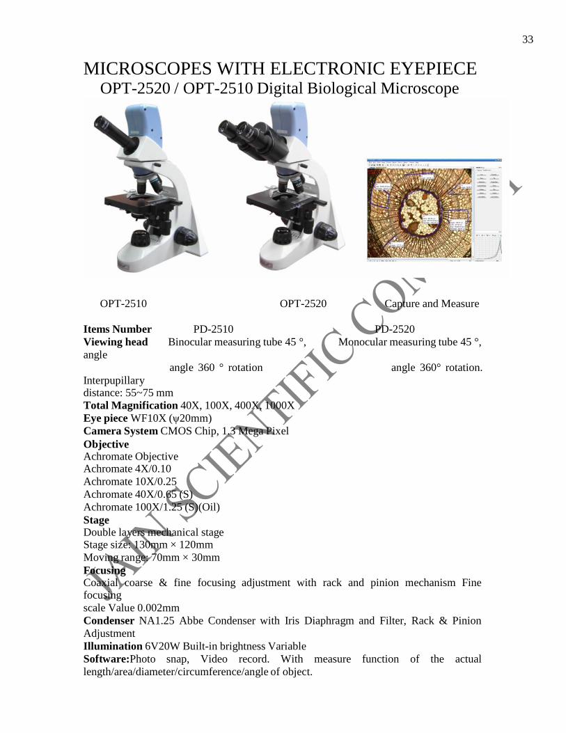
3333
MICROSCOPES WITH ELECTRONIC EYEPIECE OPT-2520 / OPT-2510 Digital Biological Microscope
OPT-2510 OPT-2520 Capture and Measure
Items Number PD-2510 PD-2520
Viewing head Binocular measuring tube 45 °, Monocular measuring tube 45 °,
angle
Interpupillary
angle 360 ° rotation angle 360° rotation.
distance: 55~75 mm
Total Magnification 40X, 100X, 400X, 1000X
Eye piece WF10X (ψ20mm)
Camera System CMOS Chip, 1.3 Mega Pixel
Objective Achromate Objective Achromate 4X/0.10
Achromate 10X/0.25
Achromate 40X/0.65 (S)
Achromate 100X/1.25 (S)(Oil)
Stage Double layers mechanical stage Stage size: 130mm × 120mm
Moving range: 70mm × 30mm
Focusing Coaxial coarse & fine focusing adjustment with rack and pinion mechanism Fine focusing
scale Value 0.002mm
Condenser NA1.25 Abbe Condenser with Iris Diaphragm and Filter, Rack & Pinion
Adjustment
Illumination 6V20W Built-in brightness Variable
Software:Photo snap, Video record. With measure function of the actual
length/area/diameter/circumference/angle of object.
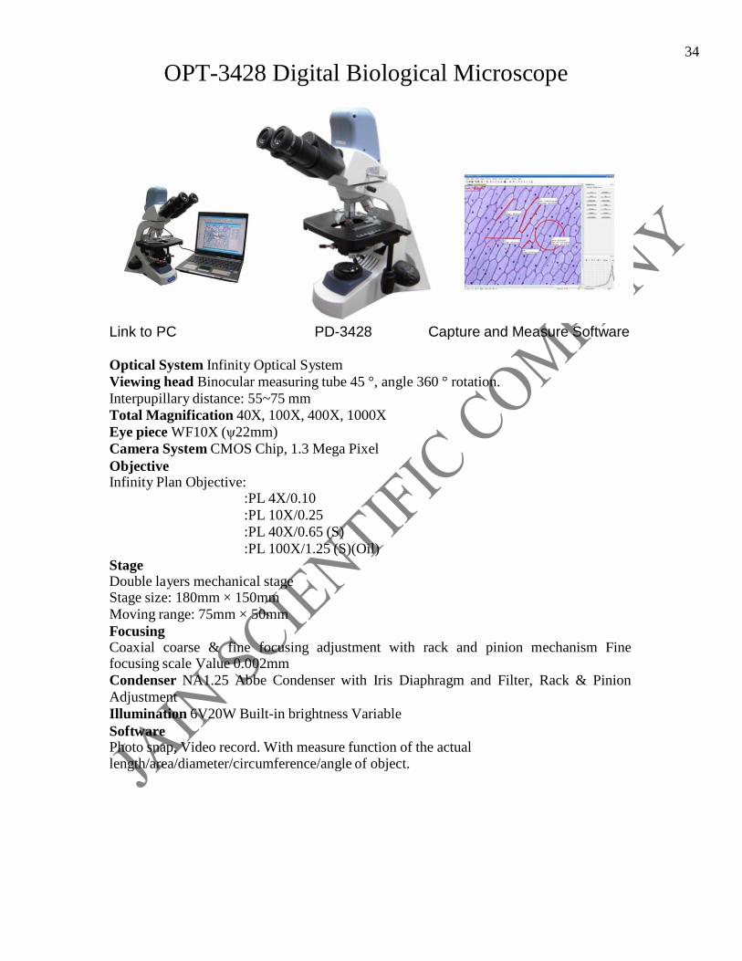
3434
OPT-3428 Digital Biological Microscope
Link to PC PD-3428 Capture and Measure Software
Optical System Infinity Optical System
Viewing head Binocular measuring tube 45 °, angle 360 ° rotation.
Interpupillary distance: 55~75 mm
Total Magnification 40X, 100X, 400X, 1000X
Eye piece WF10X (ψ22mm)
Camera System CMOS Chip, 1.3 Mega Pixel
Objective Infinity Plan Objective:
:PL 4X/0.10
:PL 10X/0.25
:PL 40X/0.65 (S)
:PL 100X/1.25 (S)(Oil)
Stage Double layers mechanical stage Stage size: 180mm × 150mm
Moving range: 75mm × 50mm
Focusing Coaxial coarse & fine focusing adjustment with rack and pinion mechanism Fine focusing scale Value 0.002mm
Condenser NA1.25 Abbe Condenser with Iris Diaphragm and Filter, Rack & Pinion
Adjustment
Illumination 6V20W Built-in brightness Variable
Software Photo snap, Video record. With measure function of the actual length/area/diameter/circumference/angle of object.

3535
OPT-60 LCD Digital Microscope
Portable Case OPT-60 Accessories
Viewing Head Monocular tube, inclined at 45°, with built-in 3.6” LCD Microscope Camera, can switch to WF
10X/16X eyepiece.
Camera System LCD: 3.6” TFT LCD Sensor: 2.0 Mega Pixel CMOS
Function: Live viewing, Photograph(JPEG), Video recording (AVI)
Memory Card: S.D.
Optical Magnification / Digital Zoom: 10X/8X
Language Option: English, Chinese, Japanese, Spanish, German, French, Italian,
Portuguese
Output: TV (PAL and NTSC), PC(USB 2.0)
Eyepiece WF10X, WF16X
Objective Achromate Objective: 4X, 10X, 40X(S)
Stage Metal stage with horizontal slide clip, X-Y moving range 50mm X 30mm
Filter 6 Colors Wheel filter: Blue, Yellow, Green, Light Green, Purple, and
Transparency
Illumination High brightness Vertical and transmitted LED light, brightness variable
Power AC 100V~240V or Two AA Batteries
Accessories 1. Microtome 2. Slide Storage Box included 5 prepared slide specimens and 5 slides.
3. Specimen Hatchery
4. Four vials of Sea Sault, Shrimp eggs, Yeast and Gum.
5. Metal Forces
6. Two AA Batteries
7. Power Adapter
8. Dust Cover
9. Portable Microscope Case

3636
Model MD130 MD-300
Total Pixel 1.3 Mega Pixel 3.0 Mega pixel
Size of Sensor ½” CMOS ½”CMOS
Resolution SXGA 1280x1024 2048x1536(7.5fps)1024x768(20fps) VGA 640x480 1024x150(30fps)1024x190(78fps)
Pixel Size 5.2um x 5.2um 3.18um x 3.18 um
Frame Rate 1280x1024(15 fps), 2048x1536(7.5 fps),1024x768(20 fps) 640x480(30 fps) 1024x510(30 fps),1024x190(78 fps)
Image Format JPG/BMP/WMV/MPG JPG/BMP/WMV/MPG
Exposure Manual/Auto Exposure Manual/Auto Exposure
SNR 54 dB 46 dB
Out port USB2.0 USB2.0
ELECTRONIC EYEPIECE MD series electronic eyepiece, adopting CMOS imaging chips with resolutions of 35 to 300 Mega Pixels, can be applied to various typical types of
Biological, Stereo, Metallurgical, Fluorescence, and Polarizing Microscopes.
FEATURES:
1. Watch live image on your computer from your microscope. Easy to take a picture
and record a video via MD software.
2. Capture clear, bright images with resolution up to 2048x1536 pixels via the USB 2.0 port.
Auto brightness and fine focus.
NOTE: Electronic Eyepiece for Telescopic systems is also available.
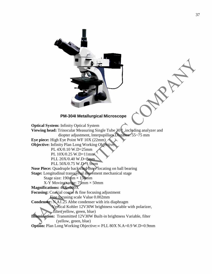
3737
PM-304I Metallurgical Microscope Optical System: Infinity Optical System
Viewing head: Trinocular Measuring Single Tube 30 ° ,including analyzer and
diopter adjustment, lnterpupillary Distance: 55~75 mm
Eye piece: High Eye Point WF 10X (22mm)
Objective: Infinity Plan Long Working Objective:
PL 4X/0.10 W.D=25mm
PL 10X/0.25 W.D=11mm
PLL 20X/0.40 W.D=8mm
PLL 50X/0.75 W.D=1.9mm
Nose Piece: Quadruple backward inner locating on ball bearing
Stage: Longitudinal transversal movement mechanical stage
Stage size: 190mm × 150mm
X-Y Moving range: 75mm × 50mm
Magnifications: 40X~500X
Focusing: Coaxial coarse & fine focusing adjustment
Fine focusing scale Value 0.002mm
Condenser: N.A1.25 Abbe condenser with iris diaphragm
Vertical Kohler 12V30W brightness variable with polarizer,
filter(yellow, green, blue)
Illumination: Transmitted 12V30W Built-in brightness Variable, filter
(yellow, green, blue)
Option: Plan Long Working Objective:∞ PLL 80X N.A=0.9 W.D=0.9mm

3838
PT-7030 Polarizing microscope
Viewing head: Trinocular, inclination at 30°,100% image light for photography capable
Eye piece: WF10X (1 pair)
10X cross eyepiece (1 piece)
10X graduation eyepiece (1 piece)
Objective: Strain-Free Achromatic DIN 4X/0.12
Strain-Free Achromatic DIN 10X/0.25
Strain-Free Achromatic DIN 40X/0.60(Spring)
Strain-Free Achromatic DIN 63X/0.75(Spring)
Nose Piece: Quadruple forward inner locating on ball bearing
Stage: Rotatable stage, Diameter Φ160mm, 360° graduated (in 1° increments), minimum
retardation resolution 6' center adjustable and with tightener
Magnifications: 40~630X
Focusing: Coaxial coarse/fine focus system, with tension adjustable and limit stopper,
minimum division of fine focusing: 2µm.
Condenser: N.A1.25 Abbe condenser with iris diaphragm
Polarizer: 360° rotatable, with four scale: 0°,90°,180°, 270°
Illumination: Upper and Down illumination: Halogen bulb 6V/30W, AC85V-230V,
with polarizer adjustable brightness
Collector: For illumination with halogen lamp With field diaphragm
Intermediate attachment: Built-in analyzer, can switch to normal observe or polarizing
observe , 90° rotatable with scale, minimum retardation
resolution 12' Bertrand lens, impellent style, center adjustable
Gypsum 1λ Compensator
Mica λ/4 Compensator
Quartz wedge compensator
Option: Strain-Free Achromatic DIN 25X/0.25, Quintuple Nosepiece
Stress-free Infinity Plan Objectives: 4×,10×,20×,40×(s),60×(s)
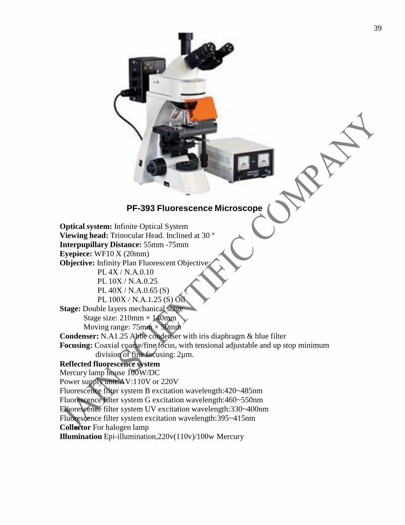
3939
PF-393 Fluorescence Microscope
Optical system: Infinite Optical System
Viewing head: Trinocular Head. Inclined at 30 °
Interpupillary Distance: 55mm -75mm
Eyepiece: WF10 X (20mm)
Objective: Infinity Plan Fluorescent Objective:
PL 4X / N.A.0.10
PL 10X / N.A.0.25
PL 40X / N.A.0.65 (S)
PL 100X / N.A.1.25 (S) Oil
Stage: Double layers mechanical stage
Stage size: 210mm × 140mm
Moving range: 75mm × 50mm
Condenser: N.A1.25 Abbe condenser with iris diaphragm & blue filter
Focusing: Coaxial coarse/fine focus, with tensional adjustable and up stop minimum
division of fine focusing: 2µm.
Reflected fluorescence system Mercury lamp house 100W/DC Power supply unit:AV:110V or 220V
Fluorescence filter system B excitation wavelength:420~485nm
Fluorescence filter system G excitation wavelength:460~550nm
Fluorescence filter system UV excitation wavelength:330~400nm
Fluorescence filter system excitation wavelength:395~415nm
Collector For halogen lamp
Illumination Epi-illumination,220v(110v)/100w Mercury

4040
CONTACT: JAIN SCIENTIFIC COMPNAY 141,CANARA APART. , SECTOR-13, ROHINI, DELHI-110085 EMAIL- [email protected], [email protected] WEBSITE- jainscientific.com RAHUL JAIN :09999576452 ASHISH SHARMA :08802449320