Test Fixture Design Presentation ICT & FCT Test...
38
IPC Presentation Test Fixture Design Presentation ICT & FCT Test Fixtures
Transcript of Test Fixture Design Presentation ICT & FCT Test...
IPC Presentation
Test Fixture Design Presentation
ICT & FCT Test Fixtures
Introduction
www.rns-usa.com 2
Quality Control is essential in production processes. In the PCB Assembly process there are several Quality Control steps or
options. The most popular tests are the electrical (In-Circuit or ICT) and the function (functional or FCT/FVT) test.
ICT test fixtures are standardized and there are several major test platforms available which are industry standards.
For FCT applications there are many more variations possible due to the vast number of testers and interface approaches
unique to each customer; also due to an endless list of applications which fall under the category of Functional Test (RF,
High Current, LED test, Leak test etc.)
Test Probes are a very important part in ICT as well as in FCT applications. If the wrong test probe (type, spring force, tip style etc.) is
used, the test fixture will not work as intended. In addition the test probe must be installed correctly in order to work properly.
This presentation will show general information and some guidelines for a proper Test Fixture design to assure the most
efficient production.
In-circuit Test for High Volume Production is nowadays almost 100% located in cheap-labor countries like China and Mexico. Only a
few products are still made in the US and most times it is only Low Volume Production with a few exceptions.
However, Functional Test has a larger market share in the US than ICT has. Some EMS Companies have their ICT equipment build in
the USA and transferred to the appropriate manufacturing site located in Asia, Mexico etc.
With this fact in mind, the existing ICT demand in the US market needs to be served professionally and in highest possible quality and
cost efficiency.
In the past 2 or 3 years FCT demand increased about 50% and at RNS the shares is about 65 : 35 (FCT : ICT).
Functional applications are more time consuming and can be even higher in cost if more special components are involved like certain
Electronic equipment or highly complex mechanical features. In the application sector FCT or FVT (Functional Verification Test) we
include HiPot, RF (High Frequency), High Current, Leak Test, ISP Programming, Test Rack, Interconnect Solutions (Connector blocks
…) etc., everything which is not 100% ICT falls under the category FCT/FVT.
There is no clear answer if ICT or FCT is higher in cost. The most important fact is to rather spend some more dollars on a
high quality test equipment for highest efficiency in PCB-Manufacturing than to just go with the cheapest price and have then
a lot of down-times on the production line because of not proper working test equipment.
Agenda
1. Introduction
2. Test Probes Basics – Terminology
3. The most common Tip Styles
4. Test Probes Life Expectancy
5. Bead Probe Technology
6. Aggressive Tip Styles
7. Passive Tip Styles
8. Common Question
9. Fixture Overview
10. Fixture Types
11. ICT vs. FCT
12. Hold Down Mechanism
13. Difficulties in Fixture Manufacturing vs. Board Design
www.rns-usa.com 3
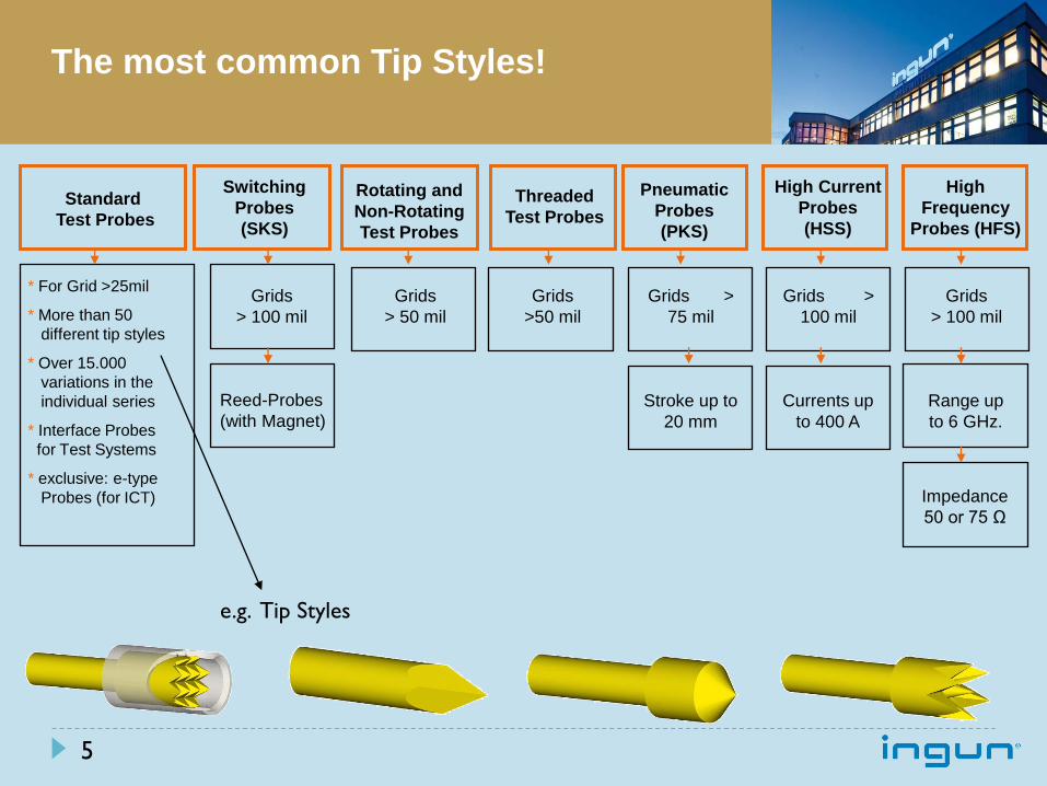
The most common Tip Styles!
* For Grid >25mil
* More than 50
different tip styles
* Over 15.000
variations in the
individual series
* Interface Probes
for Test Systems
* exclusive: e-type
Probes (for ICT)
Switching
Probes
(SKS)
Rotating and
Non-Rotating
Test Probes
Threaded
Test Probes
Pneumatic
Probes
(PKS)
High Current
Probes
(HSS)
High
Frequency
Probes (HFS)
Grids
> 100 mil
Grids
> 50 mil
Grids
>50 mil
Grids >
75 mil
Grids >
100 mil
Grids
> 100 mil
Reed-Probes
(with Magnet) Stroke up to
20 mm
Currents up
to 400 A
Impedance
50 or 75 Ω
Standard
Test Probes
e.g. Tip Styles
Range up
to 6 GHz.
5
Bead Probe Technology
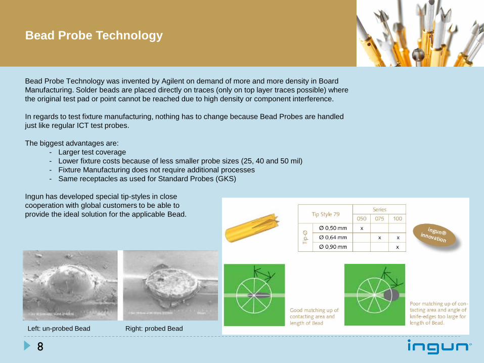
Bead Probe Technology was invented by Agilent on demand of more and more density in Board
Manufacturing. Solder beads are placed directly on traces (only on top layer traces possible) where
the original test pad or point cannot be reached due to high density or component interference.
In regards to test fixture manufacturing, nothing has to change because Bead Probes are handled
just like regular ICT test probes.
The biggest advantages are:
- Larger test coverage
- Lower fixture costs because of less smaller probe sizes (25, 40 and 50 mil)
- Fixture Manufacturing does not require additional processes
- Same receptacles as used for Standard Probes (GKS)
Ingun has developed special tip-styles in close
cooperation with global customers to be able to
provide the ideal solution for the applicable Bead.
Left: un-probed Bead Right: probed Bead
8
Bead Probe Technology
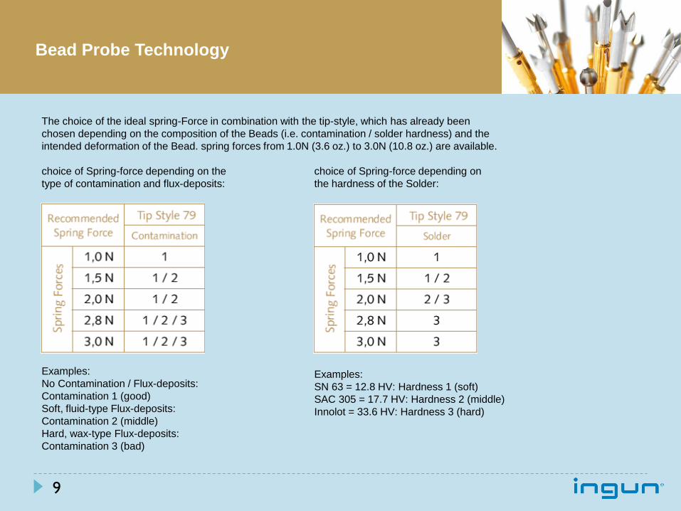
The choice of the ideal spring-Force in combination with the tip-style, which has already been
chosen depending on the composition of the Beads (i.e. contamination / solder hardness) and the
intended deformation of the Bead. spring forces from 1.0N (3.6 oz.) to 3.0N (10.8 oz.) are available.
choice of Spring-force depending on the choice of Spring-force depending on
type of contamination and flux-deposits: the hardness of the Solder:
Examples:
No Contamination / Flux-deposits:
Contamination 1 (good)
Soft, fluid-type Flux-deposits:
Contamination 2 (middle)
Hard, wax-type Flux-deposits:
Contamination 3 (bad)
Examples:
SN 63 = 12.8 HV: Hardness 1 (soft)
SAC 305 = 17.7 HV: Hardness 2 (middle)
Innolot = 33.6 HV: Hardness 3 (hard)
9
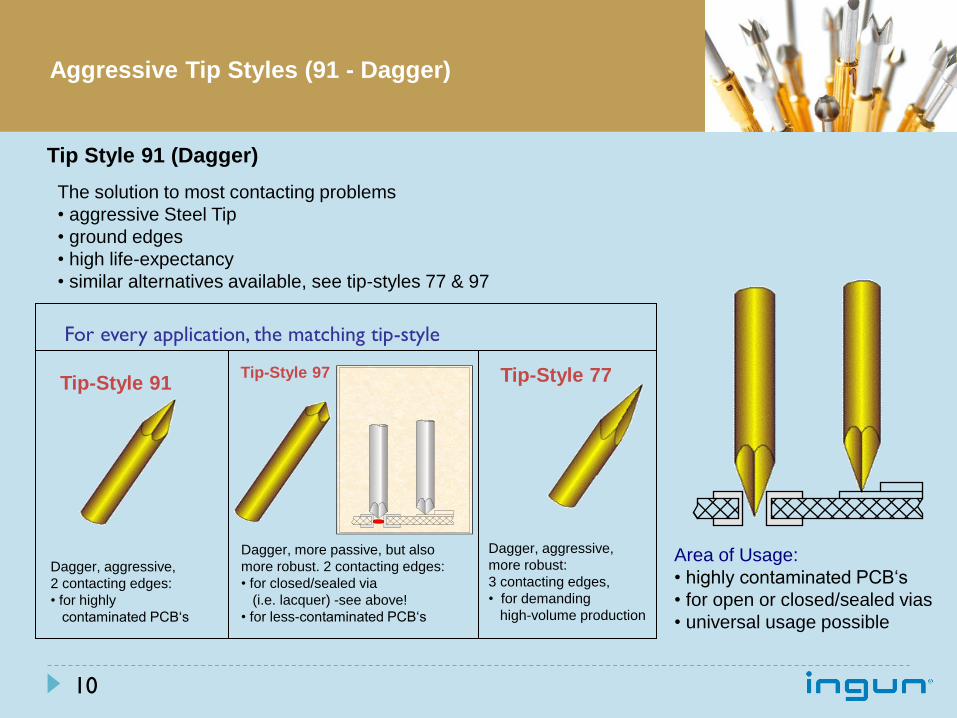
The solution to most contacting problems
• aggressive Steel Tip
• ground edges
• high life-expectancy
• similar alternatives available, see tip-styles 77 & 97
Area of Usage:
• highly contaminated PCB‘s
• for open or closed/sealed vias
• universal usage possible
Dagger, aggressive,
2 contacting edges:
• for highly
contaminated PCB‘s
Dagger, aggressive,
more robust:
3 contacting edges,
• for demanding
high-volume production
Dagger, more passive, but also
more robust. 2 contacting edges:
• for closed/sealed via
(i.e. lacquer) -see above!
• for less-contaminated PCB‘s
For every application, the matching tip-style
Tip-Style 91 Tip-Style 97 Tip-Style 77
Tip Style 91 (Dagger)
10
Aggressive Tip Styles (91 - Dagger)
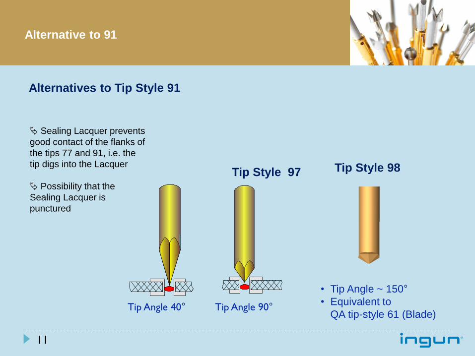
Sealing Lacquer prevents
good contact of the flanks of
the tips 77 and 91, i.e. the
tip digs into the Lacquer
Possibility that the
Sealing Lacquer is
punctured
Tip Angle 40° Tip Angle 90°
Alternatives to Tip Style 91
Tip Style 97 Tip Style 98
• Tip Angle ~ 150°
• Equivalent to
QA tip-style 61 (Blade)
11
Alternative to 91
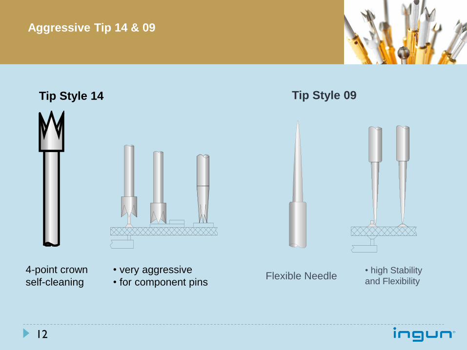
4-point crown
self-cleaning
• very aggressive
• for component pins
• high Stability
and Flexibility Flexible Needle
Tip Style 09
12
Tip Style 14
Aggressive Tip 14 & 09
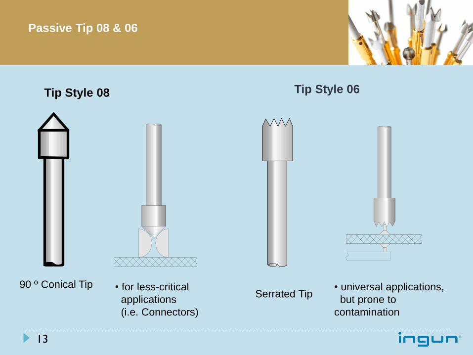
90 º Conical Tip • for less-critical
applications
(i.e. Connectors)
Serrated Tip • universal applications,
but prone to
contamination
Tip Style 06
13
Tip Style 08
Passive Tip 08 & 06
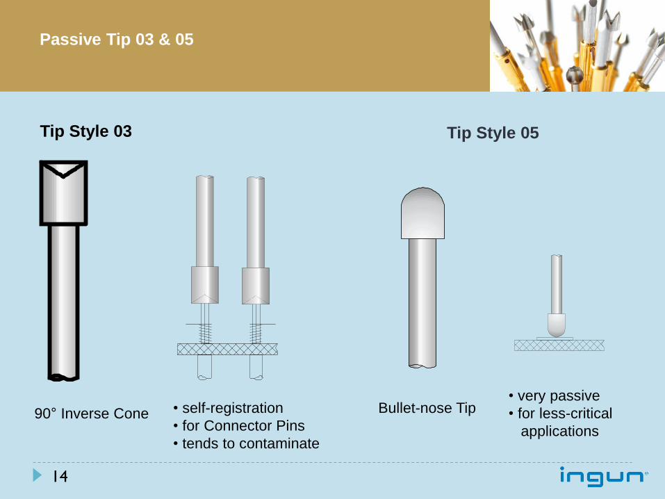
90° Inverse Cone • self-registration
• for Connector Pins
• tends to contaminate
Bullet-nose Tip • very passive
• for less-critical
applications
Tip Style 05
14
Tip Style 03
Passive Tip 03 & 05
Probe Plate Material (e.g. CEM1, FR4, Delrin etc.)
Feed of drill
Speed of drill
Grid (smaller holes are critical)
Quality of the Drilling Machine
Quality of the drill bit
Question:
What are the guidelines for the probe hole size?
Answer:
The Hole-ø and Drill-ø depends on:
For standard series INGUN have laid down drilling parameters for CEM1 und FR4
materials, however, sample drilling is unavoidable!
At RNS specific drill procedures and state-of-the-art CNC drill equipment assures
highest accuracy even on 50, 40 and 25 Mil test probes.
15
Common Question

Fixture Overview
www.rns-usa.com 16
ID Component Name
1 Cover
2 Backer Gate Frame
3 Push Plate
4 Push Tees
5 PCB (UUT)
6 Standoff (Board Stop)
7 Top Plate
8 Registration Pin
9 Probe Plate Rail
10 Probe Support Plate
11 Probe Plate
12 Vacuum Dam
13 Support Plate
14 Ground Plane
15 Test Probes / Receptacles
16 Vacuum Port
17 Fixture Pan
18 Interface cutout
19 Counter
19
1
7
18
4
17 15
10
2
3 5
11 13 16 14
6 9 12
8
Fixture Types The industry uses several standard tester platforms
HP307x, GenRad 227x, Zenthel, Spectrum …
Most common Fixture actuations
Vacuum: In ICT application Vacuum actuation is the most used technic
Pneumatic: For fixtures with a very large amount of probes pneumatic actuation is used.
Mechanical: Mostly used in Functional applications.
Most common hold-down mechanisms or Fixture Types are
Backer Gate
Vacuum Cover (Box)
ZSK – Clamshell
Mechanical/Linear Fixture
Wired and Wireless (no wires) Fixtures
Traditional ICT Fixtures are wired from Test Probes to the Interface Panel.
Sometimes a ICT Fixture is required in Wireless-Technology which means no wires are involved for
transferring signals from the test points to the Tester. In this case there are double-ended test probes
utilized in conjunction with a Transfer Board or Translator Board. The fixture stack-up is different to a
traditionally wired fixture. There is no fixture pan involved like with a wired fixture.
www.rns-usa.com 17
www.rns-usa.com 18
ICT vs. FCT
ICT is board level test (component placement and value)
Lot of test probes
Most board failures can be repaired
In-circuit Test detects:
Missing components
Disorientation of components
Improper value
FCT is a functional test (performance test)
Less test probes
After board assembly is completed
If performed without ICT, board failures can result in loss of complete assembly
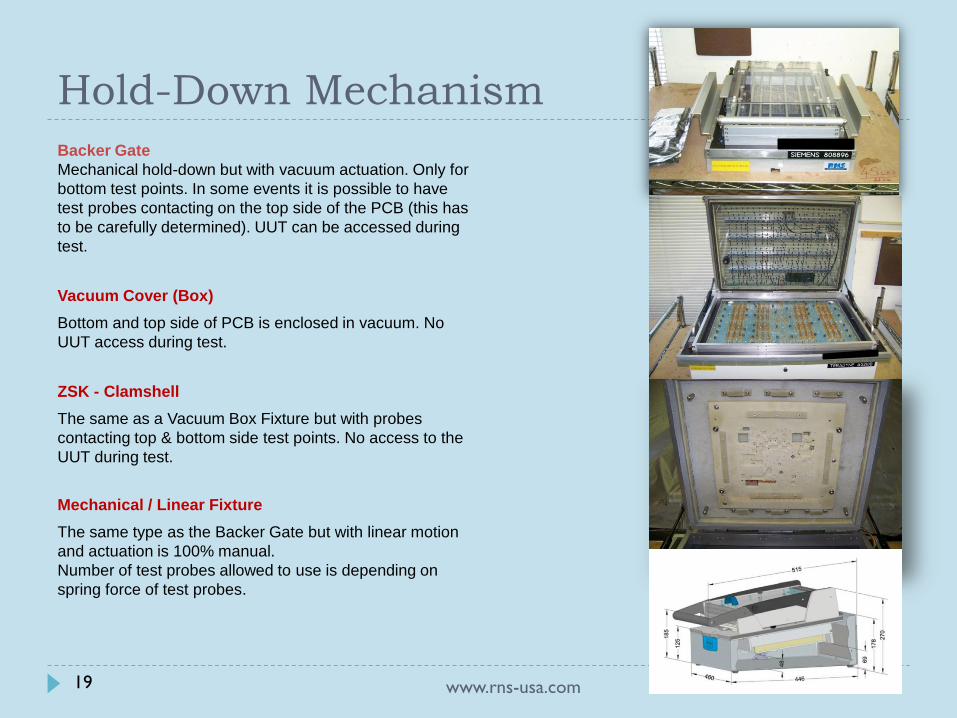
Hold-Down Mechanism
Backer Gate
Mechanical hold-down but with vacuum actuation. Only for
bottom test points. In some events it is possible to have
test probes contacting on the top side of the PCB (this has
to be carefully determined). UUT can be accessed during
test.
Vacuum Cover (Box)
Bottom and top side of PCB is enclosed in vacuum. No
UUT access during test.
ZSK - Clamshell
The same as a Vacuum Box Fixture but with probes
contacting top & bottom side test points. No access to the
UUT during test.
Mechanical / Linear Fixture
The same type as the Backer Gate but with linear motion
and actuation is 100% manual.
Number of test probes allowed to use is depending on
spring force of test probes.
www.rns-usa.com 19
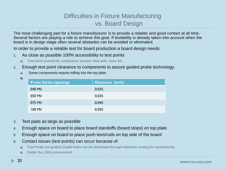
Difficulties in Fixture Manufacturing
vs. Board Design
The most challenging part for a fixture manufacturer is to provide a reliable and good contact at all time. Several factors are playing a role to achieve this goal. If testability is already taken into account when the board is in design stage often several obstacles can be avoided or eliminated.
In order to provide a reliable test for board production a board design needs:
1. As close as possible 100% accessibility to test points
a) Test point covered by component, bracket, heat sink, cover etc.
2. Enough test point clearance to components to assure guided probe technology.
a) Some components require milling into the top plate
b)
3. Test pads as large as possible
4. Enough space on board to place board standoffs (board stops) on top plate
5. Enough space on board to place push tees/rods on top side of the board
6. Contact issues (test points) can occur because of:
a) Test Probe not guided (Guide holes can be eliminated through extensive routing for components)
b) Solder flux, Dirty environment
www.rns-usa.com 20
Probe Series (spacing) Distances (inch)
040 Mil 0.035
050 Mil 0.035
075 Mil 0.045
100 Mil 0.055
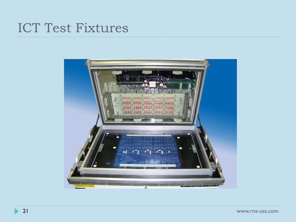
ICT Test Fixtures
www.rns-usa.com 21
Test Points Fixture Kit Size
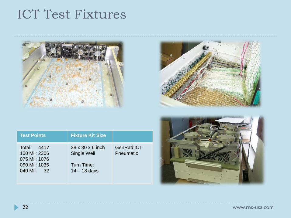
Total: 4417
100 Mil: 2306
075 Mil: 1076
050 Mil: 1035
040 Mil: 32
28 x 30 x 6 inch
Single Well
Turn Time:
14 – 18 days
GenRad ICT
Pneumatic
www.rns-usa.com
ICT Test Fixtures
22
www.rns-usa.com
Test Points Features
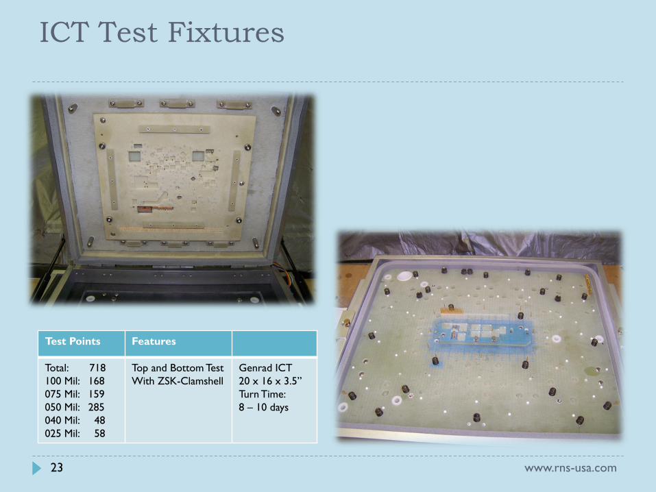
Total: 718
100 Mil: 168
075 Mil: 159
050 Mil: 285
040 Mil: 48
025 Mil: 58
Top and Bottom Test
With ZSK-Clamshell
Genrad ICT
20 x 16 x 3.5”
Turn Time:
8 – 10 days
ICT Test Fixtures
23

Test Points Fixture Kit Size
Total: 4417
100 Mil: 2306
075 Mil: 1076
050 Mil: 1035
040 Mil: 32
28 x 30 x 6 inch
Single Well
Turn Time:
14 – 18 days
GenRad ICT
Pneumatic
www.rns-usa.com 24
ICT Test Fixtures
Test Points Features
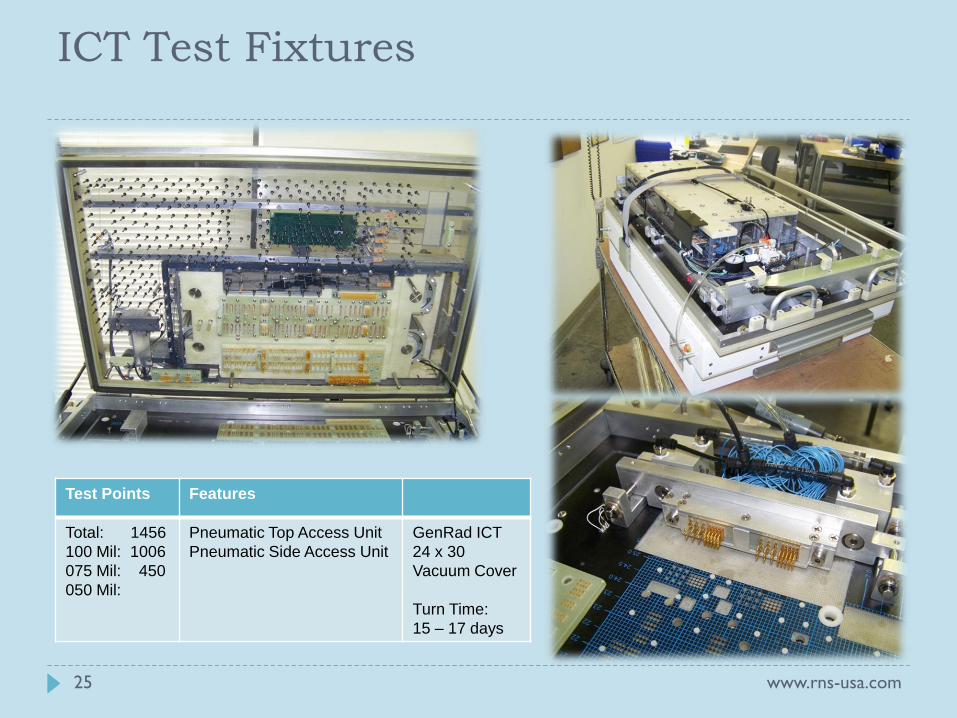
Total: 1456
100 Mil: 1006
075 Mil: 450
050 Mil:
Pneumatic Top Access Unit
Pneumatic Side Access Unit
GenRad ICT
24 x 30
Vacuum Cover
Turn Time:
15 – 17 days
www.rns-usa.com 25
ICT Test Fixtures
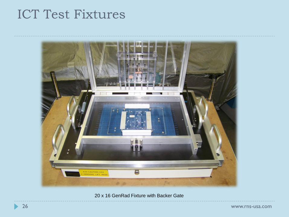
20 x 16 GenRad Fixture with Backer Gate
www.rns-usa.com 26
ICT Test Fixtures
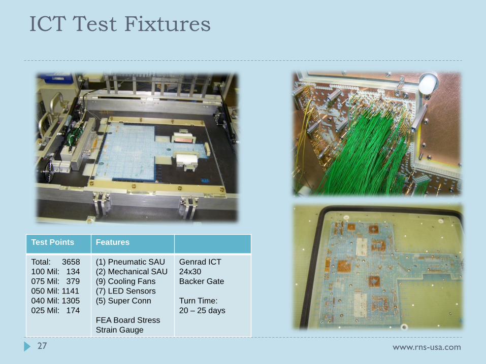
Test Points Features
Total: 3658
100 Mil: 134
075 Mil: 379
050 Mil: 1141
040 Mil: 1305
025 Mil: 174
(1) Pneumatic SAU
(2) Mechanical SAU
(9) Cooling Fans
(7) LED Sensors
(5) Super Conn
FEA Board Stress
Strain Gauge
Genrad ICT
24x30
Backer Gate
Turn Time:
20 – 25 days
www.rns-usa.com 27
ICT Test Fixtures
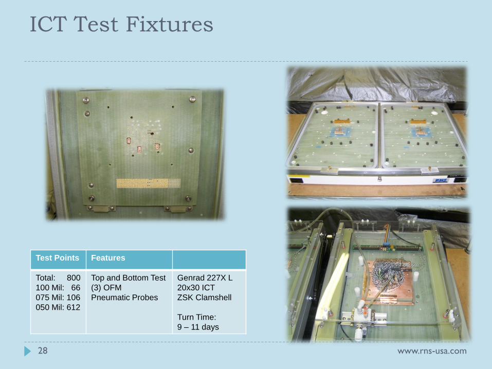
Test Points Features
Total: 800
100 Mil: 66
075 Mil: 106
050 Mil: 612
Top and Bottom Test
(3) OFM
Pneumatic Probes
Genrad 227X L
20x30 ICT
ZSK Clamshell
Turn Time:
9 – 11 days
www.rns-usa.com 28
ICT Test Fixtures
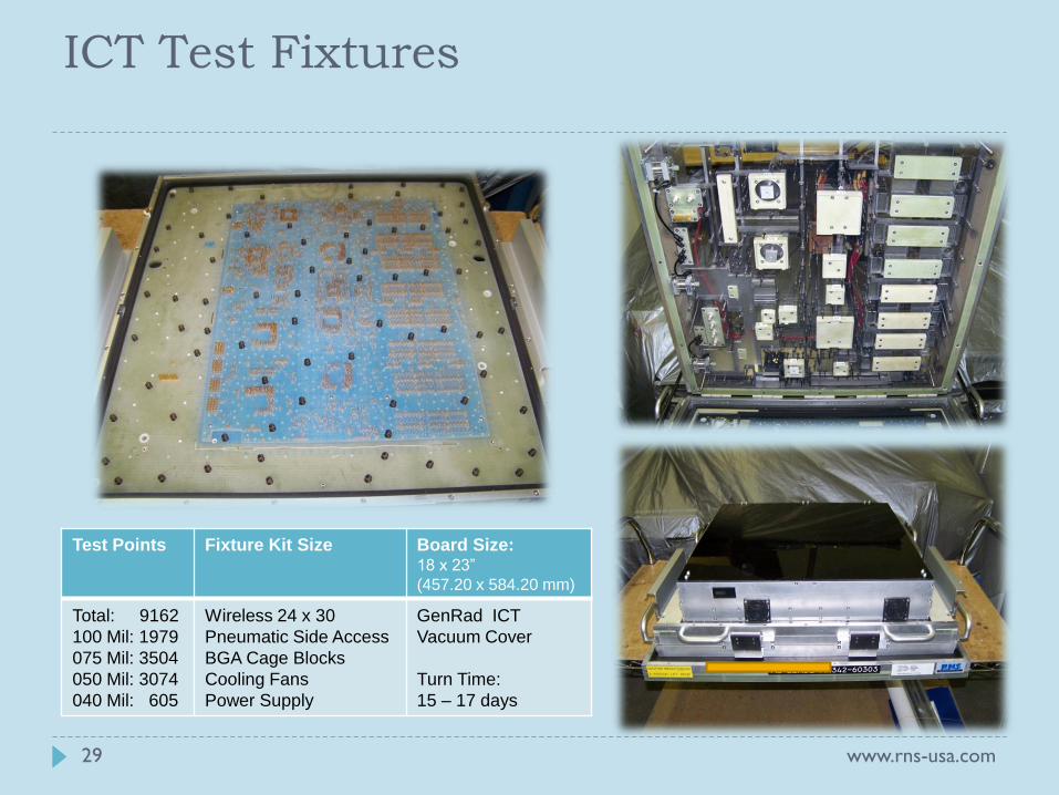
Test Points Fixture Kit Size Board Size: 18 x 23”
(457.20 x 584.20 mm)
Total: 9162
100 Mil: 1979
075 Mil: 3504
050 Mil: 3074
040 Mil: 605
Wireless 24 x 30
Pneumatic Side Access
BGA Cage Blocks
Cooling Fans
Power Supply
GenRad ICT
Vacuum Cover
Turn Time:
15 – 17 days
www.rns-usa.com 29
ICT Test Fixtures
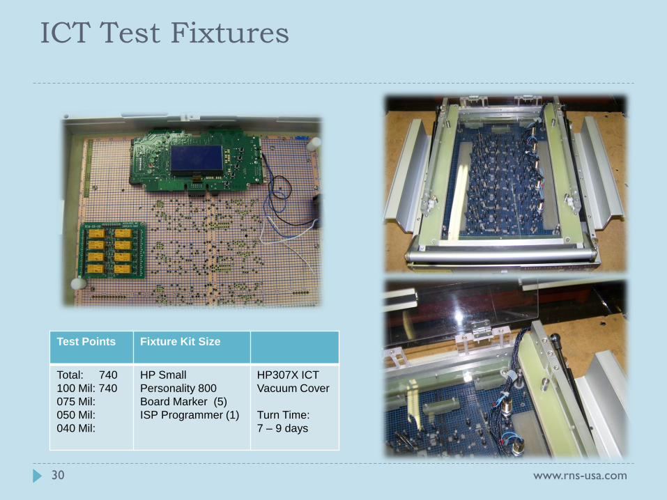
Test Points
Fixture Kit Size
Total: 740
100 Mil: 740
075 Mil:
050 Mil:
040 Mil:
HP Small
Personality 800
Board Marker (5)
ISP Programmer (1)
HP307X ICT
Vacuum Cover
Turn Time:
7 – 9 days
www.rns-usa.com 30
ICT Test Fixtures
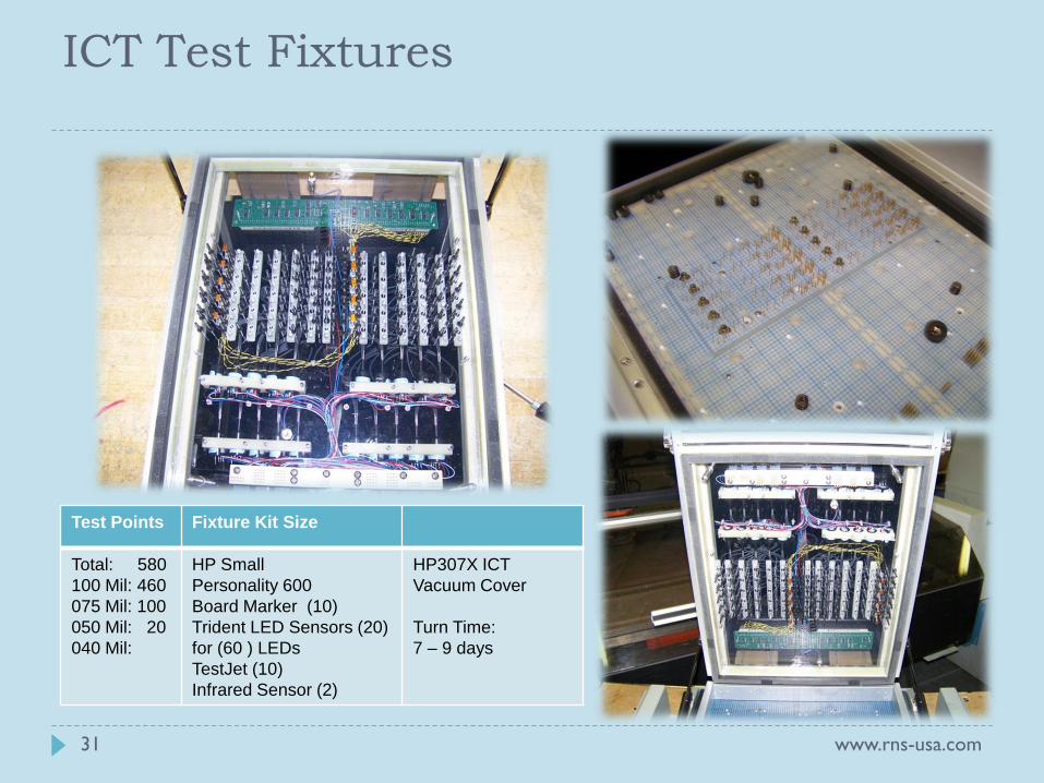
Test Points Fixture Kit Size
Total: 580
100 Mil: 460
075 Mil: 100
050 Mil: 20
040 Mil:
HP Small
Personality 600
Board Marker (10)
Trident LED Sensors (20)
for (60 ) LEDs
TestJet (10)
Infrared Sensor (2)
HP307X ICT
Vacuum Cover
Turn Time:
7 – 9 days
www.rns-usa.com 31
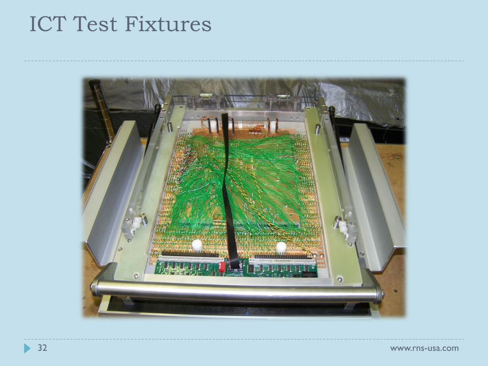
ICT Test Fixtures
www.rns-usa.com 32
ICT Test Fixtures
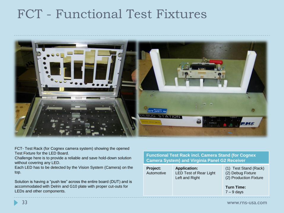
FCT- Test Rack (for Cognex camera system) showing the opened
Test Fixture for the LED Board.
Challenge here is to provide a reliable and save hold-down solution
without covering any LED.
Each LED has to be detected by the Vision System (Camera) on the
top.
Solution is having a “push tee” across the entire board (DUT) and is
accommodated with Delrin and G10 plate with proper cut-outs for
LEDs and other components.
www.rns-usa.com 33
Functional Test Rack incl. Camera Stand (for Cognex
Camera System) and Virginia Panel G2 Receiver
Project:
Automotive
Application:
LED Test of Rear Light
Left and Right
(1) Test Stand (Rack)
(2) Debug Fixture
(2) Production Fixture
Turn Time:
7 – 9 days
FCT - Functional Test Fixtures
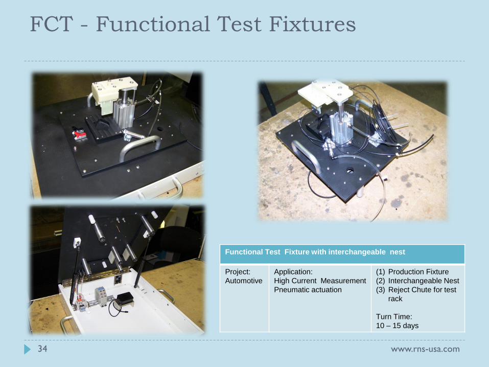
Functional Test Fixture with interchangeable nest
Project:
Automotive
Application:
High Current Measurement
Pneumatic actuation
(1) Production Fixture
(2) Interchangeable Nest
(3) Reject Chute for test
rack
Turn Time:
10 – 15 days
www.rns-usa.com 34
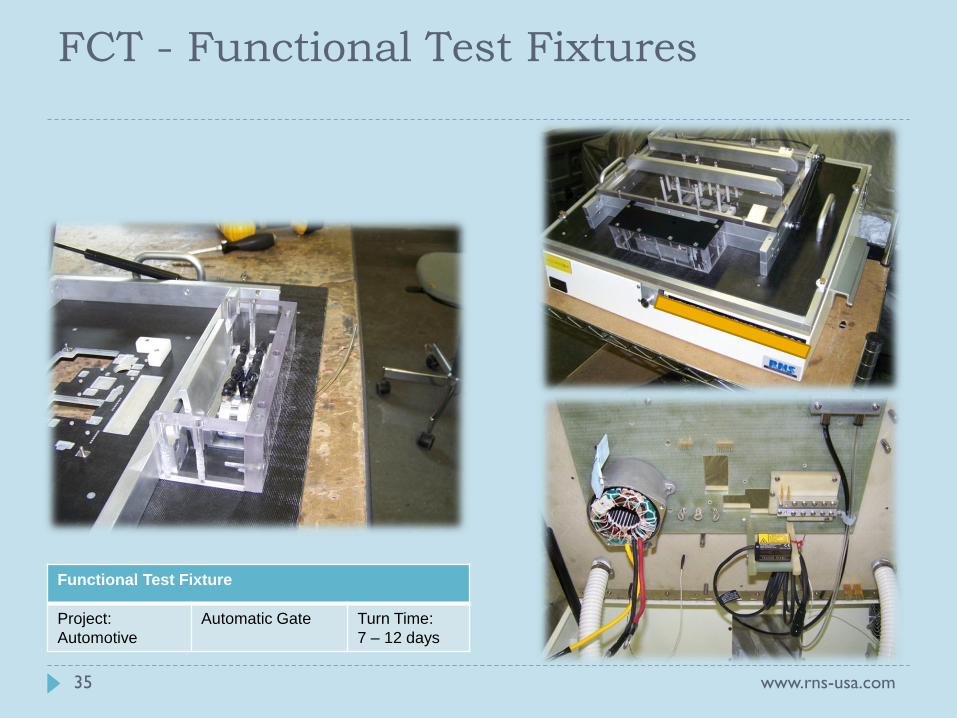
FCT - Functional Test Fixtures
www.rns-usa.com 35
Functional Test Fixture
Project:
Automotive
Automatic Gate Turn Time:
7 – 12 days
FCT - Functional Test Fixtures
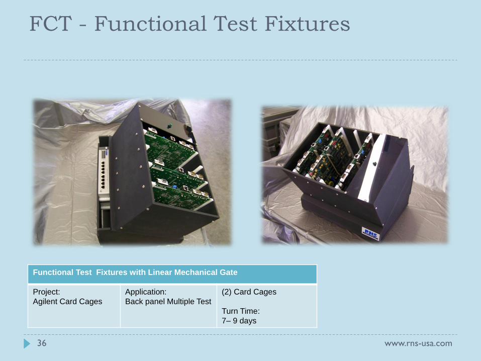
Functional Test Fixtures with Linear Mechanical Gate
Project:
Agilent Card Cages
Application:
Back panel Multiple Test
(2) Card Cages
Turn Time:
7– 9 days
www.rns-usa.com 36
FCT - Functional Test Fixtures
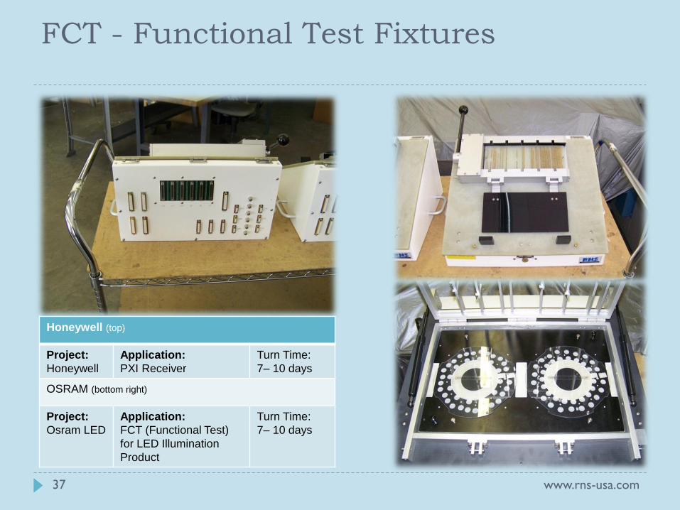
Honeywell (top)
Project:
Honeywell
Application:
PXI Receiver
Turn Time:
7– 10 days
OSRAM (bottom right)
Project:
Osram LED
Application:
FCT (Functional Test)
for LED Illumination
Product
Turn Time:
7– 10 days
www.rns-usa.com 37
FCT - Functional Test Fixtures
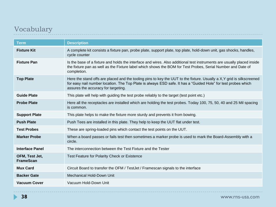
Vocabulary
Term Description
Fixture Kit A complete kit consists a fixture pan, probe plate, support plate, top plate, hold-down unit, gas shocks, handles,
cycle counter
Fixture Pan Is the base of a fixture and holds the interface and wires. Also additional test instruments are usually placed inside
the fixture pan as well as the Fixture label which shows the BOM for Test Probes, Serial Number and Date of
completion.
Top Plate Here the stand offs are placed and the tooling pins to key the UUT to the fixture. Usually a X,Y grid is silkscreened
for easy nail number location. The Top Plate is always ESD safe. It has a “Guided Hole” for test probes which
assures the accuracy for targeting.
Guide Plate This plate will help with guiding the test probe reliably to the target (test point etc.)
Probe Plate Here all the receptacles are installed which are holding the test probes. Today 100, 75, 50, 40 and 25 Mil spacing
is common.
Support Plate This plate helps to make the fixture more sturdy and prevents it from bowing.
Push Plate Push Tees are installed in this plate. They help to keep the UUT flat under test.
Test Probes These are spring-loaded pins which contact the test points on the UUT.
Marker Probe When a board passes or fails test then sometimes a marker probe is used to mark the Board-Assembly with a
circle.
Interface Panel The interconnection between the Test Fixture and the Tester
OFM, Test Jet,
FrameScan
Test Feature for Polarity Check or Existence
Mux Card Circuit Board to transfer the OFM / TestJet / Framescan signals to the interface
Backer Gate Mechanical Hold-Down Unit
Vacuum Cover Vacuum Hold-Down Unit
38 www.rns-usa.com
Term Description
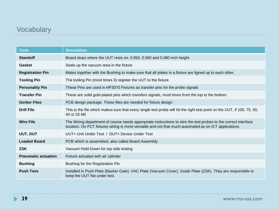
Standoff Board stops where the UUT rests on. 0.050, 0.060 and 0.080 inch height
Gasket Seals up the vacuum area in the fixture
Registration Pin Mates together with the Bushing to make sure that all plates in a fixture are ligned up to each other.
Tooling Pin The tooling Pin (most times 3) register the UUT to the fixture.
Personality Pin These Pins are used in HP3070 Fixtures as transfer pins for the probe signals
Transfer Pin These are solid gold-plated pins which transfers signals, most times from the top to the bottom.
Gerber Files PCB design package. These files are needed for fixture design
Drill File This is the file which makes sure that every single test probe will hit the right test point on the UUT, if 100, 75, 50,
40 or 25 Mil
Wire File The Wiring department of course needs appropriate instructions to wire the test probes to the correct interface
location. On FCT fixtures wiring is more versatile and not that much automated as on ICT applications.
UUT, DUT UUT= Unit Under Test / DUT= Device Under Test
Loaded Board PCB which is assembled, also called Board Assembly
ZSK Vacuum Hold-Down for top side testing
Pneumatic actuation Fixture actuated with air cylinder
Bushing Bushing for the Registration Pin
Push Tees Installed in Push Plate (Backer Gate), VAC Plate (Vacuum Cover), Guide Plate (ZSK). They are responsible to
keep the UUT flat under test.
Vocabulary
39 www.rns-usa.com
Vocabulary
40 www.rns-usa.com
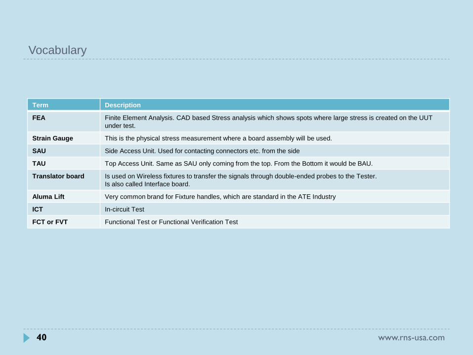
Term Description
FEA Finite Element Analysis. CAD based Stress analysis which shows spots where large stress is created on the UUT
under test.
Strain Gauge This is the physical stress measurement where a board assembly will be used.
SAU Side Access Unit. Used for contacting connectors etc. from the side
TAU Top Access Unit. Same as SAU only coming from the top. From the Bottom it would be BAU.
Translator board Is used on Wireless fixtures to transfer the signals through double-ended probes to the Tester.
Is also called Interface board.
Aluma Lift Very common brand for Fixture handles, which are standard in the ATE Industry
ICT In-circuit Test
FCT or FVT Functional Test or Functional Verification Test
More Information Also see Fixture References for example projects (see CD)
www.rns-usa.com/cms
For Technical questions and Support please contact: Greg Dorsey: [email protected] Sven F. Nocher: [email protected]
Test Equipment ICT/FCT • Test Probes • Interconnect Solutions
ISP Programming • LED Digital Analyzer • Color Sensors
Test Plugs • Engineering Services
Precision CNC Machining • Assembly Services
RNS International, Inc. 5001 Sirus Lane Ph (704) 329 0444 [email protected] Charlotte, NC 28208 Fax (704) 329 0404 [email protected]
www.rns-usa.com
www.rns-usa.com 41