TELECOM CABLES (COPPER)
62
TELECOM CABLES
Transcript of TELECOM CABLES (COPPER)

TELECOM CABLES

CABLE
UNDER GROUND
ETHERNET SWITCH BOARD
OVER HEAD
OUTDOOR INDOOR
STP
UTP
DROP WIRE FIELD
SERVICE CABLE
OFC PIJF

STP CABLE
Shielded Twisted Pair
Protected Against Electrical Interference
More Cost than UTP

UTP CABLE
• Unshielded Twisted Pair
• Unprotected against electrical interference
• Cheaper than STP

DROP WIRE
• Conductor Dia: 0.5mm,
• Type : Single Pair
• Size : 100m , 200m, 500m
• Insulation : PVC
• Joint : Direct pair to pair ,
use sleeve or electric tape
• Used for providing single pair circuit like ADM phone etc from nearest distribution point (DP)

FIELD SERVICE CABLE(D-8) • Used for temporary extension of a circuit
during emergencies like accident, flood etc.
• Supplied in drums of 500m, 1000m
• Contains 4 strands of copper for conductivity and 3 strands of steel for strength( dia 0.375mm).
• Jointing is done straight copper to copper and steel to steel, sleeve or electric tape are used.

How Cross-talk Is Eliminated in Twisted Pair
7
3v
2v
2v
3v 3v
2v 2v
L1
L2
L1=3+2+3+2= 10V L2=2+3+2+3= 10V
Net induced voltages on L1&L2 are the same, no potential
difference, no current flow at telephone and no cross-talk from
adjacent Circuits.
ADJACENT CIRCUIT
Span-2 Span-1 span-3 Span-4

SWITCH BOARD CABLE • Used for extension of circuits inside a building or
between equipment located indoors.
• Rip cord is provided inside to remove PVC sheath easily.
• Comes with 3p, 5p, 10p, 20p, 50p, 100p
• Comes in size of 100m,200m,500m
• Conductor dia is 0.4mm/0.5mm/0.6mm
• After termination of cable pairs soldering shall be done other than krone and wago CTBs.
• Can be UTP or STP type.
Dia Loop
resistance/km
0.4 mm 286 ohm
0.5mm 184 ohm
0.6 mm 128 ohm

SWITCH BOARD CABLE COLOUR CODE(Scheme-1) 20 PAIR
1) BLUE -WHITE
2) ORANGE- WHITE
3) GREEN - WHITE
4) BROWN -WHITE
5) SLATE -WHITE
6) BLUE WHITE- WHITE
7) ORANGE WHITE- WHITE
8) GREEN WHITE- WHITE
9) BROWN WHITE- WHITE
10) SLATE WHITE- WHITE
11)BLUE ORANGE-WHITE
12)BLUE GREEN -WHITE
13)BLUE BROWN -WHITE
14)BLUE SLATE –WHITE
15)ORANGE GREEN – WHITE
16)ORANGE BROWN- WHITE
17)ORANGE SLATE-WHITE
18)GREEN BROWN-WHITE
19)GREEN SLATE – WHITE
20)BROWN SLATE -WHITE

M
A
I
N
C
O
L
O
U
R
M A T E C O L O U R S
B L U E
O R A N G E
G R E E N
B R O W N
S L A T E
W H I T E R E D B L A C K Y E L L O W
P A I R 1
P A I R 2
P A I R 3
P A I R 4
P A I R 5
P A I R 6 P A I R 1 1 P A I R 1 6
P A I R 7 P A I R 1 2 P A I R 1 7
P A I R 8 P A I R 1 3 P A I R 1 8
P A I R 9 P A I R 1 4 P A I R 1 9
P A I R 1 0 P A I R 1 5 P A I R 2 0
SWITCH BOARD CABLE COLOUR CODE(Scheme-2)

50 pair Switch board and PIJF cable colour code
B L U E
O R A N G E
G R E E N
B R O W N
S L A T E
W H I T E R E D
P A I R 1
P A I R 2
P A I R 3
P A I R 4
P A I R 5
P A I R 6
P A I R 7
P A I R 8
P A I R 9
P A I R 1 0
P a i r
P a i r - 1 1 t o 2 0
P a i r - 2 1 t o 3 0
P a i r - 3 1 t o 4 0
P a i r - 4 1 t o 5 0
B i n d e r
P a i r - 1 t o 1 0
P A I R N O 3 2 B R O W N B i n d e r
O R A N G E W H I T E

P a i r
P a i r - 2 1 t o 4 0
P a i r - 4 1 t o 6 0
P a i r - 6 1 t o 8 0
P a i r - 8 1 t o 1 0 0
B i n d e r
P a i r - 1 t o 2 0
P A I R N O 5 7 G R E E N B i n d e r
O R A N G E Y E L L O W
100 pair Switch board and PIJF cable colour code

TESTING OF SWITCH BOARD CABLE
• ALL cables to be tested( end to end) once in year. and record the parameters.
• Insulation resistance value should be more than 50M ohm/km.
• Loop resistance should be tested, value should be in accordance to dia.

Data Cables


PIJF(Polythene Insulated Jelly Filled) Cable • Advantages
1) Counting of Pair is easy and human errors are avoided.
2) Failures are less.
3) Entry of water is prevented by jelly.
4) Cable can be directly terminated to MDF/CTB/Tag block/equipment thus avoiding number of joints.
5) Cable life is more.
6) Cable is not delicate therefore less chances of damage due to rodent attack.

PIJF CABLE(Paired) Application Telephone connection to subscribers, Local lead/
last mile connectivity for voice and data circuits.
Conductor dia 0.5mm , 0.63mm
Pairs 5p, 10p, 20p, 50p, 100p
Drum length 500 m, 1000m
Loop resistance 184 ohm(0.5mm dia), 128 ohm(0.63mm dia)
Insulation 5000 Mega ohm per km
Characteristic Impedance 600 Ohm
Minimum Bending Radius
15 X cable dia

PIJF CABLE CONSTRUCTION(Paired)

Polythene Outer jacket Protects cable armour from chemical reactions/rusting, external temperature
Galvanized Steel Tape Mechanical protection from jerks
Polythene Tape Isolation between armour and inner sheath
Polythene Inner sheath Protection of Poly-Al laminated sheath
Poly-Al-Laminated Tape Protection from electromagnetic induction, also prevents moisture to enter
Core wrapping (Polyester) tape
For filling up petroleum jelly
Polythene Insulated Copper Conductor
For conduction (colour of insulation are for pair identification)

QUAD CABLES
• “STAR QUAD” is Four conductor balanced cable, four wires form a tighter, more consistent pack then two wires can and can resist even more noise.
20

• Blue and white wires are vertically opposite and form a pair of wires
• Red and Slate wires are vertically opposite and form another pair.
• Same amount of interference reaches to blue and white wires but slightly different amount to Red and Slate wires, but as all 4 wires are twisted together combined induction will be same for all 4 wires.
QUAD CABLES

22
where
R-is the resistance per unit length, L- is the inductance per unit length, G- is the conductance of the
dielectric per unit length, C-is the capacitance per unit length,
For no attenuation RC=LG
Value of RC is greater in cable, therefore to achieve RC=LG , inductor(loading coils) of value
118 mH are connected in series with each pair. The distance between two consecutive
loading coils is called loading section and it is 2000 m. However it is seldom used now as
Quad cable is not being used for long distance circuits.
Schematic representation of the elementary
components of a transmission Line.

UNLOADED QUAD CABLE IMPORTANT POINTS
1) Conductor Dia - 0.9mm
2) Loop Resistance : 56 Ohm/km
3) Transmission Loss: 0.63dB/ km at 800Hz, 1.2dB/km at 2kHz(for axle counter) , must not exceed 30dB for a block section
4) Insulation Resistance: 10M ohm for block section
20 M ohm for block section (For axle counter)
5) Characteristic Impedance: 470 ohms

COLOUR CODE & QUAD ALLOCATION of 6 QUAD CABLE
QUAD
No
COLOUR OF INSULATION CIRCUIT
A-Wire B-Wire C-Wire D-Wire With OFC Without OFC
1 Orange White Red Grey Block Instrument Block Instrument
2 Blue White Red Grey Spare for Block Section Control
3 Brown White Red Grey E.C CKT E.C CKT
4 Green White Red Grey 4/1-LC GATE
4/2- BPAC
4/1-BPAC
4/2--LC GATE
5 Yellow White Red Grey BPAC(Block Proving
by axle counter)
BPAC
6 Black White Red Grey TAWS(Train
automatic warning
system)
TAWS
24

1. Loop Resistance Test Monthly
2. Checking Attenuation Monthly
3. Checking Cross Talk Level Quarterly
4. Checking Noise Level Quarterly
5. Insulation Resistance Test Yearly
6. Earth Resistance measurement- Half yearly
Test should be carried out when proper disconnection is accepted by control
25
Schedule of Testing & Measurements in Quad Cable

CONDUCTION TEST a) Purpose : to measure the
loop resistance of conductors
which indicates the condition
of joints.
b) Measuring instrument used:
Ohm meter or Multimeter
c) Periodicity: Monthly
d) Standard value: 56Ω/km
26

TRANSMISSION LOSS TEST a) Purpose : To measure the dB loss of
the system (cable).
b) Instrument used: TMS
(Transmission measuring set).
c) Periodicity: Monthly
d) Standard Value: 0.63dB/km at 800Hz
1.2dB/km at 2kHz
27
Osc
o/p
Level meter
i/p
Osc
o/p
Level meter
i/p

INSULATION RESISTANCE TEST
a) Purpose : To know the proper insulation of the conductor.
b) Instrument used: 100V DC meggar
c) Periodicity: Annual
d) Standard Value: 10 MΩ for block section
20 MΩ for block section
( for axle counter)
Note : All other conductors of the cable shall be shorted with armour(Earth) during test
28

Checking Cross Talk Level
A) Purpose : To Check Crosstalk From Other Pair
B)Meter Used: Oscillator And Level Meter
C) Periodicity: Quarterly
D) Standard Value: Better Than -55 dB
For NEXT And FEXT
Checking Noise Level
A) Purpose : To Check Level Of Noise
B) Meter Used: Psophometer
C) Periodicity: Quarterly
D) Standard Value: Less Than 2mili Volt
Earth Resistance at Armour : Shall be less than 1 Ohm

CONSTRUCTION OF 6Q CABLE 1. Conductor
2. Petroleum jelly
3. Dummy tube
4. Binder
5. Polyester tape
6. Poly aluminum tape
7. PVC inner jacket
8. Aluminum wire screen
9. Woven tape(yellow color)
10. PVC intermediate jacket
11. G.I. Steel armour
12. PVC outer jacket
30

Induced Voltage in RE area • In RE area induced voltage in Quad cable due to electrostatic and
electromagnetic coupling from 25kv catenary can be very high(approx. 87.5V/km). This voltage adds up with increase in length.
• To reduce this; Armour, Al screen and Poly aluminum tape all three must be earthed ( < 1 ohm) at both ends(stations). This reduces the induced voltage to 8.75V/km making quad cable safe for working. Continuity of Armour, Al screen and Poly aluminum tape must be ensured at all joints.
• Continuity should be checked during routine cable test.
Note : Any fault/negligence will buildup high voltage up to several hundred volts which is fatal for workmen and equipments.

Cable Markers
RCC cable markers shall normally be provided at a distance of every 50 meters on the cable route, at derivations and also to be provided at all types of cable joints. They should be of standard RCC with letters " IR / 6 QUAD CABLE " and logo engraved and painted. They shall be painted with green when placed at joint locations and painted with red for normal indication.

Typical 6 Quad cable failures & their causes
1. Cable burnt at joint due to lightning and all circuits failed- Armour connectivity at joint is given up.
2. Cable is noisy while train passing in the section BPAC circuit frequently failing- improper earthing of cable armour.
3. Cable cuts and thefts- Ensure the cable laid with in Railway Boundary, avoid the exposing of cable, implement the Railway Board JPO for Earth Digging works by Engg. Dept, Update the cable route diagrams and upload to web page for easy access to concerned dept.
4. Codal life of Cable- Plan for replacement of cable with in codal life(20 years).
33

Marking on Cable
a) Name/Trade mark of the manufacturer
b) IRS Specification number
c) Year of manufacture
d) Length (Sequential marking)
e) Cable drum number
f) No. of pairs/conductor size (Example: 20 pairs/0.63mm)
This marking exists throughout the length at intervals of one metre.

Connectors used for Cable Termination

Krone type connector

Wago

Tag Block

CT box for Quad cable

OFC(Optical Fiber Cable) It is a method of transmitting information from one place to another by sending light through hair thin optical fiber, generally made of silica, using the principle of Total Internal Reflection.
The process of communicating using fiber-optics involves the following basic steps:
Creating the optical signal using a transmitter(Laser diode or LED)
Transmitting the signal along the fiber.
Receiving the optical signal and converting it into an electrical signal(Photo Transistor)

Merits of OFC Huge Bandwidth
No Electromagnetic and Electrostatic interference
Low attenuation ( 0.25 db/km at 1550 nm)
Self healing rings under NMS control
No cross talk
Safety and Signal security
Less chance of theft
Flexibility in system upgradation

Demerits of OFC Difficulty in Jointing ( splicing )
Highly skilled staff would be required for maintenance
Precision and costly instruments are required
Tapping for emergency and gate communication is difficult.
Negligible resale value
Special interface equipments required for Block working

Application OF OFC IN RAILWAYS
All data communication networks( PRS & UTS,FOIS)
Railnet
Trunk connectivity
Control communication
Vital signaling circuits (Axle counter, UFSBI, Data logger)

DESIGN OF OFC

Works on the Principal of Total Internal Reflection.
Angle of incidence > critical angle
Refractive index of Core is more than Cladding as core is denser medium and clad is rarer medium.


Difference between Single (SM) &multimode(MM) fiber SM MM
Core dia= 8-10 µm Core dia= 50-62.5 µm
Clad dia= 125 µm Clad dia= 125 µm
Signal quality higher
Signal quality lower
Bandwidth higher
Bandwidth lower
Step index only
Step & graded index both
Smaller core diameter
Larger core diameter
Suitable for long distance
Suitable for shorter distance
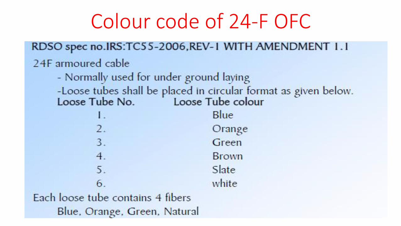
Colour code of 24-F OFC

Colour code of 24-F OFC Tube Colour
1-Blue 1-Blue 2-org 3-green 4-Natural
2-Orange 5-Blue 6-org 7-green 8-Natural
3-Green 9-Blue 10-org 11-green 12-Natural
4-Brown 13-Blue 14-org 15-green 16-Natural
5-Slate 17-Blue 18-org 19-green 20-Natural
6-White 21-Blue 22-org 23-green 24-Natural


Transmission Loss in OFC At 1310 nm wavelength: 0.35dB/km
At 1550nm wavelength: 0.25dB/km
Attenuation in OFC is Caused by
Scattering : Due to impurities or irregularities present in the physical construction of Fiber light rays scatter in various directions.
Absorption : Hydroxyl ions (OH- ions, water) in the silica absorb energy of the transmitted signal
Macrobending loss: Caused by the bending of entire fiber axis. ( To avoid Bending radius should be more than 30 X dia of cable)
Microbending loss : Due to micro deformation in fiber axis
Dispersion : Spreading of transmitted light , unit is picosecond/nm-km

Splicing
Max. permitted splice loss in case of fusion splicing is 0.1dB.

Steps for Fusion Splicing Remove Outer jacket, Armor and sheath using slitter.
Clean loose tubes using cotton.
Remove loose tubes using stripper.
Remove Primary coating using stripper.
Clean the fibers using isopropyl and tissue paper.
Cut fibers at 90 degrees using cleaver.
Put sleeve on individual fibers.
Place and align fibers between electrodes of splicing machine.
Using Splicing machine Fuse the fibers with electric arc ensure loss below 0.1dB if not then break the joint and repeat the process of splicing.
Cover spliced portion with sleeve and apply heat in heat chamber.
Arrange the fibers in tray.

Tools for fusion splicing

Tools for cable preparation for fusion splicing

Measurements in OFC Optical light source and Optical Power meter

OTDR(Optical Time Domain Reflectometer)
Used to evaluate parameters such as splice losses, fiber attenuation etc.
Works on the principle of Fresnel reflection and Rayleigh backscatter .
Gives very accurate location of cable cut/fiber break or defective joints.


OFC Connectors Attenuators

FDMS(Fiber Distribution and management System)

THANKS