Technical Requirements for MV Power Cables with Rated Voltage ...
34
Specification – Technical Requirements for MV Power Cables with Rated Voltage from 3.81/6.6(7.2) kV to 19/33(36) kV Standard Number: HPC-8DJ-03-0004-2013
Transcript of Technical Requirements for MV Power Cables with Rated Voltage ...
Specification – Technical Requirements for MV Power Cables with Rated Voltage from 3.81/6.6(7.2) kV to 19/33(36) kV
Standard Number: HPC-8DJ-03-0004-2013
CS10#1759243 Page 2 of 34 Print Date 15/04/2016
© Horizon Power Corporation – Document Number: HPC-8DJ-03-0004-2013
Uncontrolled document when printed. Printed copy expires one week from print date. Refer to Document No. for current version.
Document Control
Author Name: Viswa Easwaran
Position: Standards Engineer
(on file)
Author (Revision 1) Name: Anthony Seneviratne
Position: Standards Engineer
Reviewer Name: Adrian Barnes
Position: Standards Engineer
Document Owner
(May also be the Process Owner)
Name: Paul Savig
Position: Senior Standards Engineer
Approved By * Name: Justin Murphy
Position: Manager Asset Management Services
Date Created/Last Updated April 2016
Review Frequency ** 3 yearly
Next Review Date ** April 2019
* Shall be the Process Owner and is the person assigned authority and responsibility for managing the whole process, end-to-end, which may extend across more than one division and/or functions, in order to deliver agreed business results.
** Frequency period is dependent upon circumstances– maximum is 5 years from last issue, review, or revision whichever is the latest. If left blank, the default shall be 1 year unless otherwise specified.
Revision Control
Revision Date Description
0 28/05/2013 First Issue
1 17/02/2016 Cypermethrin residue limit added
STAKEHOLDERS The following positions shall be consulted if an update or review is required:
Manager Engineering & Project Services Regional Asset Managers
Manager Capacity Management Services
Manager Asset Management Services

CS10#1759243 Page 3 of 34 Print Date 15/04/2016
© Horizon Power Corporation – Document Number: HPC-8DJ-03-0004-2013
Uncontrolled document when printed. Printed copy expires one week from print date. Refer to Document No. for current version.
TABLE OF CONTENTS
1 SCOPE ......................................................................................................... 5
2 NORMATIVE REFERENCES ....................................................................... 5
2.1 Standards ............................................................................................................... 5
2.2 Definitions and Abbreviations ................................................................................. 6
2.2.1 Definitions ............................................................................................................................... 6
2.2.2 Abbreviations .......................................................................................................................... 7
2.3 Drawings ................................................................................................................ 7
3 REQUIREMENTS ......................................................................................... 7
3.1 Power System Particulars ....................................................................................... 7
3.1.1 Rated Voltages ....................................................................................................................... 7
3.1.2 Fault Rating ............................................................................................................................. 7
3.1.3 Maximum Conductor Temperatures ....................................................................................... 8
3.1.4 Nominal System Frequency .................................................................................................... 8
3.1.5 System Insulation Levels ........................................................................................................ 8
3.2 Service Conditions .................................................................................................. 8
3.2.1 Environmental Conditions ....................................................................................................... 8
3.2.2 Operating Conditions .............................................................................................................. 8
3.3 Description of Cable ............................................................................................... 9
3.4 Materials and Construction ..................................................................................... 9
3.4.1 General ................................................................................................................................... 9
3.4.2 Cable Construction ................................................................................................................. 9
3.4.3 Conductor ............................................................................................................................... 9
3.4.4 Conductor Screen ................................................................................................................... 9
3.4.5 Insulation ................................................................................................................................. 9
3.4.5.1 Material ................................................................................................................................................. 9
3.4.5.2 Thickness .............................................................................................................................................. 9
3.4.6 Insulation Screen .................................................................................................................... 9
3.4.7 Metallic Screen ..................................................................................................................... 10
3.4.8 Laying-up .............................................................................................................................. 10
3.4.9 Bedding/Fillers ...................................................................................................................... 10
3.4.10 Water Blocking ...................................................................................................................... 10
3.4.11 Outer-Sheath ........................................................................................................................ 10
3.4.12 Core Marking ........................................................................................................................ 11
3.4.13 Cable Markings ..................................................................................................................... 11
3.4.14 Protection from Insect Attack ................................................................................................ 12
3.5 Cable Length ........................................................................................................ 13
3.6 Cable Bending Radius .......................................................................................... 13

CS10#1759243 Page 4 of 34 Print Date 15/04/2016
© Horizon Power Corporation – Document Number: HPC-8DJ-03-0004-2013
Uncontrolled document when printed. Printed copy expires one week from print date. Refer to Document No. for current version.
3.7 Cable Pulling Tension ........................................................................................... 13
3.8 Cable-end Sealing ................................................................................................ 13
4 CABLE DRUMS ......................................................................................... 14
4.1 Timber Drums ....................................................................................................... 14
4.2 Steel Drum ........................................................................................................... 14
4.3 Drum Marking ....................................................................................................... 15
5 STORAGE .................................................................................................. 15
6 RELIABILITY .............................................................................................. 15
7 SAFETY ...................................................................................................... 15
8 ENVIRONMENTAL CONSIDERATIONS ................................................... 16
9 TESTS ........................................................................................................ 16
9.1 Test Requirements ............................................................................................... 16
9.1.1 Type Tests ............................................................................................................................ 16
9.1.2 Routine and Sample Tests ................................................................................................... 16
10 DOCUMENTATION AND SAMPLES ......................................................... 17
10.1 Type Test Certificates/Reports ............................................................................. 17
10.2 Samples ............................................................................................................... 17
10.2.1 Test Samples ........................................................................................................................ 17
10.2.2 Display Samples ................................................................................................................... 17
APPENDIX A – REVISION INFORMATION ......................................................................................................... 18
APPENDIX B – QUALITY ASSURANCE (TO BE COMPLETED BY STORES) ................................................... 19
APPENDIX C – SCHEDULES A & B: ENQUIRY DOCUMENT ............................................................................ 21
APPENDIX D – SCHEDULE C: COMPLIANCE DOCUMENT .............................................................................. 25
APPENDIX E – SCHEDULE D: DEPARTURES FROM TECHNICAL SPECIFICATION ...................................... 27
APPENDIX F – CABLE DESCRIPTION ................................................................................................................ 28
APPENDIX G – STANDARD TIMBER DRUM DIMENSIONS ............................................................................... 31
APPENDIX H – SCHEDULE E: TEST REPORT REQUIREMENTS FOR CHEMICAL PROTECTION ................ 33
APPENDIX I – SPECIFICATION DRAWINGS ...................................................................................................... 34

CS10#1759243 Page 5 of 34 Print Date 15/04/2016
© Horizon Power Corporation – Document Number: HPC-8DJ-03-0004-2013
Uncontrolled document when printed. Printed copy expires one week from print date. Refer to Document No. for current version.
1 SCOPE
This specification covers Horizon Power's requirements for the supply and testing of medium-voltage distribution power cables used on AC systems from 3.81/6.6(7.2) kV to and including 19/33(36) kV.
Tests prescribed will evaluate the performance of these cables, and shall comply with this specification.
NOTE: Submersible cables are not included as part of this specification.
Approval in terms of this specification shall be obtained by one or a combination of the following:
a) successful completion of the appropriate tests required by this specification by an independent and accredited test authority.
b) provision of test certificates from an independent and accredited test authority based upon an alternative specification, with test requirements at least equivalent to this specification.
NOTE: Verification of accreditation of the test authority shall be provided by NATA (National Association of Testing Authorities) accredited test house or by a test house possessing accreditation from a NATA MRA (Mutual Recognition Agreement) partner.
2 NORMATIVE REFERENCES
2.1 Standards
The following documents contain provisions that, through reference in the text, constitute requirements of this specification. At the time of publication, the editions indicated were valid. All standards and specifications are subject to revision, and parties to agreements based on this specification are encouraged to investigate the possibility of applying the most recent editions of the documents listed below. Information on currently valid national and international standards and specifications can be obtained from SAI Global – Standards On-Line data base or equivalent standards database.
Table 1: List of Applicable Standards
STANDARD DESCRIPTION
AS/NZS 1125 Conductors in insulated electric cables and flexible cords
AS/NZS 1429:1 Electric Cables – Polymeric Insulated – For voltages 1.9/3.3(3.6) kV up to and including 19/33/(36) kV

CS10#1759243 Page 6 of 34 Print Date 15/04/2016
© Horizon Power Corporation – Document Number: HPC-8DJ-03-0004-2013
Uncontrolled document when printed. Printed copy expires one week from print date. Refer to Document No. for current version.
STANDARD DESCRIPTION
AS/NZS 1660 Test methods for electric cables, cords and conductors.
Part 2.2 - Insulation, extruded semi-conductive screens and non-metallic sheaths. Methods specific to elastomeric and XLPE compounds
Part 2.3 - Insulation, extruded semi-conductive screens and non-metallic sheaths. Methods specific to PVC and halogen free thermoplastic compounds
Part 2.4 - Insulation, extruded semi-conductive screens and non-metallic sheaths. Methods specific to polyethylene and polypropylene compounds
Part 3- Electrical tests
Part 4 - Complete cable and flexible cord
AS 1824.2 Insulation Coordination: Part 2 – Phase to Earth and Phase to Phase above 1 kV
AS 1931.1 High Voltage Testing Techniques - General Definitions and Test Requirements
AS 2067 Substations and high voltage installations exceeding 1 kV a.c.
AS/NZS 2857 Timber Drums for Insulated Electric Cables and Bare Conductors
AS/NZS 3000 Electrical Installations (known as Australian/New Zealand Wiring Rules)
AS/NZS 3008 Electrical installations - Selection of cables
Part 1 - Cables for alternating voltages up to and including 0.6/1 kV
AS/NZS 3599.2 Electric cables — Aerial bundled — Polymeric insulated — Voltages 6.35/11(12) kV and 12.7/22(24) kV - Part 2: Non-metallic screened
AS/NZS 3808 Insulating and sheathing materials for electrical cables
AS/NZS 3983 Metal drums for insulated electric cables and bare conductors
AS/NZS 4026 Electric Cables – For underground residential distribution systems
ICEA S-94-649-2004
Standard for Concentric Neutral Cables Rated 5 through 46 kV
IEC 60183 Guide to the selection of high-voltage cables
VDE 0298 Part 4 – General Current Ratings for flexible cables
In addition to the above, Horizon Power Environmental Conditions HPC-9EJ-01-0001-2013 shall be referred to for environmental conditions, in addition to those stated in section 3.2.
2.2 Definitions and Abbreviations
For the purposes of this specification the following definitions apply:
2.2.1 Definitions
1) nominal voltage: according to DIN VDE 0298 cables are specified as U0/U (Um) where:
a) U0 is the cable nominal voltage between the conductor and the metal covering or earth;
b) U is the cable nominal voltage between the phase conductors, for
3-phase 𝑈 = √3𝑈0;

CS10#1759243 Page 7 of 34 Print Date 15/04/2016
© Horizon Power Corporation – Document Number: HPC-8DJ-03-0004-2013
Uncontrolled document when printed. Printed copy expires one week from print date. Refer to Document No. for current version.
c) Um is the maximum permissible voltage.
This defines the voltages of cables and wires, by which the construction and the tests in respect of electrical characteristics are to be referred.
2) Equipment: means cable in relation to this specification.
2.2.2 Abbreviations
1) AC: Alternating Current
2) AMF: Approved Manufacturing Facility
3) AS: Australian Standard
4) AWA: Aluminium-wire armoured
5) HDPE: High Density Polyethylene
6) MRA: Mutual Recognition Agreement
7) MV: Medium Voltage >1000 volts ac; <36 000 volts ac
8) NATA: National Association of Testing Authorities, Australia
9) PVC: Polyvinyl Chloride
10) SWA: Steel-wire armoured
11) XLPE: Cross-linked polyethylene
2.3 Drawings
The drawing listed below form part of this specification, see Appendix I:
1) HPA-SD-E-01010-01 (MV 1C Power Cable)
3 REQUIREMENTS
3.1 Power System Particulars
The Equipment shall be suitable for continuous connection to a power system with the characteristics covered by this Section.
3.1.1 Rated Voltages
The rated voltages Uo/U (Um) of cables considered in this specification shall be as specified in AS/NZS 1429.1.
3.1.2 Fault Rating
The cables shall be rated to withstand the following 3 phase fault currents:
1) 13.1 kA rms/1s for 33 kV
2) 18.4 kA rms/1s for 22 kV
3) 18.4 kA rms/1s for 11 kV
4) 21.9 kA rms/1s for 6.6 kV
CS10#1759243 Page 8 of 34 Print Date 15/04/2016
© Horizon Power Corporation – Document Number: HPC-8DJ-03-0004-2013
Uncontrolled document when printed. Printed copy expires one week from print date. Refer to Document No. for current version.
3.1.3 Maximum Conductor Temperatures
The cables shall be suitable for use with conductor temperatures specified in AS/NZS 1429.1 for normal operation and under fault conditions.
3.1.4 Nominal System Frequency
The nominal system frequency is 50 Hz.
3.1.5 System Insulation Levels
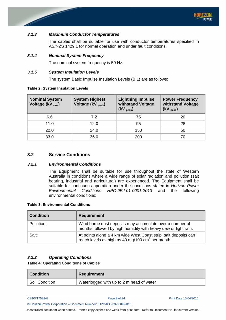
The system Basic Impulse Insulation Levels (BIL) are as follows:
Table 2: System Insulation Levels
Nominal System Voltage (kV rms)
System Highest Voltage (kV peak)
Lightning Impulse withstand Voltage (kV peak)
Power Frequency withstand Voltage (kV peak)
6.6 7.2 75 20
11.0 12.0 95 28
22.0 24.0 150 50
33.0 36.0 200 70
3.2 Service Conditions
3.2.1 Environmental Conditions
The Equipment shall be suitable for use throughout the state of Western Australia in conditions where a wide range of solar radiation and pollution (salt bearing, industrial and agricultural) are experienced. The Equipment shall be suitable for continuous operation under the conditions stated in Horizon Power Environmental Conditions HPC-9EJ-01-0001-2013 and the following environmental conditions:
Table 3: Environmental Conditions
Condition Requirement
Pollution: Wind borne dust deposits may accumulate over a number of months followed by high humidity with heavy dew or light rain.
Salt: At points along a 4 km wide West Coast strip, salt deposits can reach levels as high as 40 mg/100 cm2 per month.
3.2.2 Operating Conditions
Table 4: Operating Conditions of Cables
Condition Requirement
Soil Condition Waterlogged with up to 2 m head of water
CS10#1759243 Page 9 of 34 Print Date 15/04/2016
© Horizon Power Corporation – Document Number: HPC-8DJ-03-0004-2013
Uncontrolled document when printed. Printed copy expires one week from print date. Refer to Document No. for current version.
Condition Requirement
Depth of Laying 850 mm measured from ground surface to top of a cable/trefoil or duct
3.3 Description of Cable
Cables shall have a method of identification for asset management purposes i.e. a means of capturing batch information for traceability of any future problems with the cables. In addition, a discrete means of identification of stolen cable shall be proposed. Full details of the application of the identification marking and method to read or retrieve the information shall be provided with the submission. The identification marking shall be indelible and difficult to remove from the cable.
3.4 Materials and Construction
Cable sizes used by Horizon Power are captured in Appendix F.
3.4.1 General
All 22 kV and 33 kV medium voltage underground distribution cables shall comply with AS/NZS 1429.1 unless otherwise specified.
3.4.2 Cable Construction
The cable construction shall comply with AS/NZS 1429.1.
3.4.3 Conductor
Conductors shall be stranded circular compacted aluminium or copper as stated in Appendix C Schedule A and comply with the requirements of AS/NZS 1429.1.
Core conductors shall be as stated in Appendix C Schedule A.
3.4.4 Conductor Screen
The conductor screen shall comply with the requirements of AS/NZS 1429.1.
3.4.5 Insulation
3.4.5.1 Material
The insulation material shall be of dry-cured cross-link polyethylene (XLPE) compound in accordance with AS/NZS 3808.
3.4.5.2 Thickness
The average insulation thickness shall be determined in accordance with AS/NZS 1429.1 Tables 2.1 and 2.2.
3.4.6 Insulation Screen
The extruded semi-conductive insulation screen shall meet the minimum stripping force as defined in AS/NZS 1429.1 and the maximum stripping force requirement as specified in Table 5.

CS10#1759243 Page 10 of 34 Print Date 15/04/2016
© Horizon Power Corporation – Document Number: HPC-8DJ-03-0004-2013
Uncontrolled document when printed. Printed copy expires one week from print date. Refer to Document No. for current version.
Table 5: Stripping force requirement
Nominal System Voltage
(kV rms)
Stripping Force Requirement
22 Up to 45 N
33 Up to 65 N
3.4.7 Metallic Screen
The gross cross-sectional area of screen wires shall be not less than that calculated by the adiabatic method as specified in AS/NZS 1429.1 to meet the following single phase to earth fault current for 1 second as stated in Table 6:
Table 6: Single-phase fault current design requirements
Conductor Material Cross-sectional Area of Core Conductor (mm2)
Fault Current Level (kA) – Copper Wire Screen
Aluminium 35 3.3
Aluminium 50 4.8
Aluminium 95 9.1
Aluminium 185-1000 10
Copper 240 10
Copper 630 10
The screen wires shall comprise plain or tinned annealed copper wires in accordance with AS/NZS 1429.1. The screen wires shall not indent the insulation by more than that allowed by Standard ICEA S-94-649-2004. The diameter of the screen wires shall not be greater than 1.7 mm.
3.4.8 Laying-up
For triplex cables, AS/NZS 1429.1 shall be adhered to.
3.4.9 Bedding/Fillers
Not required.
3.4.10 Water Blocking
Medium voltage underground cables shall have a non-biodegradable longitudinal moisture barrier in the form of a water-swellable tape, applied over the metallic screen wires and shall meet the water blocking test requirements of AS/NZS 1429.1 Appendix C.
The water-swellable tape shall be easily removable and shall separate cleanly from the screen wires.
3.4.11 Outer-Sheath
Outer-sheath materials shall comply with the requirements of AS/NZS 3808 and shall be of a composite construction comprising an inner 5V-90 orange PVC

CS10#1759243 Page 11 of 34 Print Date 15/04/2016
© Horizon Power Corporation – Document Number: HPC-8DJ-03-0004-2013
Uncontrolled document when printed. Printed copy expires one week from print date. Refer to Document No. for current version.
layer and an outer black HDPE layer. The HDPE layer shall be UV stabilised with a minimum of 2% carbon black. The minimum average thickness of the outer HDPE layer shall be not less than 2 mm. The combined PVC and HDPE average sheath thickness shall be not less than 3.2 mm and shall comply with all other requirements of AS/NZS 1429.1.
The HDPE sheath shall have a high resistance to stress cracking (i.e. the Environmental Stress Crack Resistance) and the Elongation at Break (without ageing) must be in excess of the minimum requirements specified in Table 10 of AS/NZS 3808) and the Vendor is requested to provide specific assurance in this regard.
The Vendor shall specify the:
1) resistance to corrosion; and
2) permeability to water
of the HDPE sheath.
NOTE: The colour orange shall be within the range of colours described by RAL colour standards 2003, 2004, 2005, 2007, 2008, 2009, 2011. Variations in colour intensity are expected and shall not be a reason for rejection.
3.4.12 Core Marking
Core (phase) identification marking on the semi-conductive insulation screen and outer sheath shall only be applied where specified in Appendix C Schedule A.
Where core (phase) identification is specified in Appendix C Schedule A, the height of core (phase) identification marking on the semi-conductive insulation screen shall be at least 5 mm and all other core (phase) identification aspects shall be in accordance with AS/NZS 1429.1.
3.4.13 Cable Markings
The outer sheath shall be indelibly marked:
1) By dual embossing (approximately diametrically opposed lines for distribution power cables) and single line embossing (for service cables) at intervals of not more than 500 mm showing:
a) Manufacturer's name
b) Place of manufacture
c) Voltage rating
d) Phase conductor size and material
e) Designation of insulation (i.e. XLPE)
f) Batch Number
g) The word "UNDERGROUND"

CS10#1759243 Page 12 of 34 Print Date 15/04/2016
© Horizon Power Corporation – Document Number: HPC-8DJ-03-0004-2013
Uncontrolled document when printed. Printed copy expires one week from print date. Refer to Document No. for current version.
2) Additionally, in a single line, at intervals of one metre there shall be at least three sets of the following marking in a contrasting colour equally spaced as practicable within the one metre interval:
a) Week and year of manufacture e.g. 02/2013 for the 2nd week in year 2013
b) Where relevant, a minimum of 3-letter identification for cable as having protection from insect attack i.e. DBT for double brass tape, NYL for Nylon or TCD for termicide.
3) Metre marking, e.g. <018M> representing 18 -metres, shall be provided on the cable in a contrasting colour.
All of these sheath markings shall comply with the requirements of AS/NZS 1429.1 except that the minimum height shall be 5 mm.
Example of cable marking on outer sheath of the cable with protection from insect attack (double brass tape) for a 1 m interval shall be as shown in Figure 1, as appropriate, with phase marking as specified in Appendix C Schedule A.
Figure 1: Cable Marking
3.4.14 Protection from Insect Attack
Protection from insect attack shall be provided in the form of one, or a combination of the following options:
1) Double Brass Tape
Where double brass tape is provided, it shall consist of two overlapping layers of tape having the same width, helically applied. The layers shall be applied such that:
a) A nominal design gap of 25% is maintained between consecutive helical windings on each of the layers

CS10#1759243 Page 13 of 34 Print Date 15/04/2016
© Horizon Power Corporation – Document Number: HPC-8DJ-03-0004-2013
Uncontrolled document when printed. Printed copy expires one week from print date. Refer to Document No. for current version.
b) The top layer shall be centrally applied over the design gaps of the bottom layer.
c) The double brass tape shall be applied directly over the 5V-90 insulating sheath and covered by an outer sheath of HDPE material containing a minimum of 2% carbon black.
2) Chemical Protection
Where chemical protection is offered, it shall be incorporated into an outer sheath comprising of HDPE material which contains a minimum of 2% carbon black.
Unless the use of the chemical has been approved at the time of issue of this specification, the Vendor shall provide the following information:
a) Material safety data sheet refer to Appendix H Schedule E;
b) Test reports;
c) Letter of approval from an authorised environmental representative;
d) Indication of the period the chemical will remain effective;
e) Limits or restrictions imposed on the installation of chemically treated cables;
f) Explanation in the manner/mechanism by which the chemical functions to protect the cable from insects; and
g) Cypermethrin residue on the cable surface shall not exceed 3.0 mg/m² determined by a controlled swab test over a minimum test sample of area 0.01 m².
3.5 Cable Length
Cables shall be supplied in drum lengths of 250 m as a minimum unless otherwise indicated in Appendix C Schedule A.
3.6 Cable Bending Radius
The Vendor shall provide the minimum bending radius for the installing and setting of cables in Appendix C Schedule B.
3.7 Cable Pulling Tension
The Vendor shall provide the maximum pulling tension for cables offered in Appendix C Schedule B.
3.8 Cable-end Sealing
Cables shall be free of water or corrosion at the time of dispatch from the manufacturer’s premises.
All cable ends shall be sealed to prevent moisture ingress. This shall seal the individual layers of the cable construction from one another to avoid water transfer to the conductor strands in the event of damage to the outer sheaths.
Vendors shall provide full details of the method used for sealing the cables ends with the tender documentation. The minimum requiremetns for seals at the cable

CS10#1759243 Page 14 of 34 Print Date 15/04/2016
© Horizon Power Corporation – Document Number: HPC-8DJ-03-0004-2013
Uncontrolled document when printed. Printed copy expires one week from print date. Refer to Document No. for current version.
ends shall be an air-tight seal fitted with a pressure release valve (allowing airflow from inside the cap to the outside only).
4 CABLE DRUMS
4.1 Timber Drums
Cable drum reels shall be constructed generally in accordance with the requirements of AS 2857, including/in addition to the following:
1) Flange layers shall be fastened with flat head nails complying with the requirements of AS 2334. Nails shall be positioned concentrically with the flange on pitch circles and the heads of nails shall be punched below the surface on the inside of the flange.
2) The nails shall be of sufficient length to provide an effective clinch of no less than 10 mm. Clinches shall be so driven that the points of the nails are below the outer surface of the flange.
3) Barrel and flanges shall be securely clamped together with barrel bolts. Bolt threads may be rolled or cut. Bolts shall be evenly spaced and shall not project more than 12 mm beyond the nuts after the nuts have been fully tightened.
4) Barrel supports shall be provided as per Section 3 of AS 2857.
5) When lagging is required, battens shall be secured with steel tape banding adjacent to each flange and secured with nails or staples that will not protrude through the battens. Banding shall be painted or galvanized and shall be no less than 0.65 mm thick and 32 mm wide.
6) Nominal drum dimensions shall be in accordance with Table 3.1 of AS/NZS 2857 and as extended in range by the table in Appendix G (Note actual drum dimensions may vary slightly from those listed in Appendix G and in such cases the requirements of the closest nominal size shall prevail meeting the requirements of Appendix F). Maximum flange diameter acceptable is 2.45 m.
Cables drums shall be suitably lagged with timber for transportation.
Cable ends shall be securely affixed to the drum flange to prevent them from being dislodged. Any cable ends that project from the drum flanges shall be adequately protected against mechanical damage during transport and storage. They shall give complete protection from damage, to the cable during transit.
4.2 Steel Drum
Steel drum construction and preparation shall comply with the requirements of AS 3983 for the supply of cables and conductors with the exception of drum dimensions, which shall meet the minimum barrel diameter and maximum flange and width specified in Appendix F.
Clearance between the top layer of cable and periphery of drum flange shall be equal to the overall diameter of the cable or 50 mm, whichever is the greater.

CS10#1759243 Page 15 of 34 Print Date 15/04/2016
© Horizon Power Corporation – Document Number: HPC-8DJ-03-0004-2013
Uncontrolled document when printed. Printed copy expires one week from print date. Refer to Document No. for current version.
4.3 Drum Marking
Drums shall be clearly labelled/stencilled with the following information:
1) Manufacturers name;
2) Manufacturers drum traceability number;
3) Week and Year of manufacture;
4) Appropriate identification/information of the cable in the form of:
a) Number of cores, phase conductor size and material
b) Designated voltage expressed in the form of Uo/U
c) Insulation, sheath and other protective covering materials
d) Where the cable is metre marked, the start and finish numbers of the cable's metre marking
5) Batch Number
6) Total gross weight of cable, drum and lagging;
7) Arrow to indicate direction of rotation of the drum marked with the words "ROLL THIS WAY";
8) Directions to indicate correct methods of lifting and transporting cable drums;
9) Specification Number;
10) Stock number;
11) Order number; and
12) Length of cable.
5 STORAGE
The Equipment shall be capable of being stored without deterioration within the temperature range of -10 °C to + 45 °C for at least 24 months.
6 RELIABILITY
Vendors shall provide information on the reliability of the Equipment and the performance of the materials offered over an operational life of 65 years under the specified field of application and conditions of service.
Information provided shall evidence the claimed reliability and performance for the Equipment offered, including information on Failure Mode and Effect Analysis.
7 SAFETY
Material Safety Data Sheets (MSDS) applicable for each different Equipment or chemical ingredient in the Equipment which is considered harmful to personnel or environment in any manner shall be supplied with the Proposal.
CS10#1759243 Page 16 of 34 Print Date 15/04/2016
© Horizon Power Corporation – Document Number: HPC-8DJ-03-0004-2013
Uncontrolled document when printed. Printed copy expires one week from print date. Refer to Document No. for current version.
8 ENVIRONMENTAL CONSIDERATIONS
Vendors shall provide information on the environmental soundness of the design and the materials used in the manufacture of the Equipment offered. In particular, information must address such issues as recyclability and disposability at the end of service life as well as disposability of materials supplied.
9 TESTS
9.1 Test Requirements
The Vendor shall, prior to first Delivery, complete the type, routine, sample and special tests and inspections as required by the relevant Australian Standards including AS 1429.1 Section 3.
The passing of such tests shall not prejudice the right of Horizon Power to reject the cable if it does not comply with the Specification when installed.
9.1.1 Type Tests
A representative selection of cables shall be Type tested in accordance with this specification and the relevant Australian Standards. Horizon Power reserves the right to witness Type Tests and shall be given advance notice by the Vendor to be available to witness such tests.
Type Testing shall be undertaken by a NATA (National Association of Testing Authorities) accredited test house or by a test house possessing accreditation from a NATA MRA (Mutual Recognition Agreement) partner. A formal report covering the outcome of the testing shall be provided to Horizon Power.
Evidence shall be submitted by the Vendor indicating that all type tests required by the relevant Australian Standards listed in Table 1 have been satisfactorily carried out.
Where Cable has been tested to International Standards only, sufficient type test evidence shall be submitted to confirm equivalence of Cable performance to the relevant Australian standard.
9.1.2 Routine and Sample Tests
Horizon Power reserves the right to witness an agreed program of Routine Tests to assure of the competence of the manufacturing facility to deliver consistently conforming Cable. The Vendor shall in all cases make all necessary provisions with the testing and/or manufacturing facilities to enable witnessing to take place. An Inspection and Test Plan (ITP) shall be provided to Horizon Power prior witnessing of tests.
Prior to first delivery of Cable, the Vendor shall submit to Horizon Power all routine and sample tests performed on that batch of Cable.

CS10#1759243 Page 17 of 34 Print Date 15/04/2016
© Horizon Power Corporation – Document Number: HPC-8DJ-03-0004-2013
Uncontrolled document when printed. Printed copy expires one week from print date. Refer to Document No. for current version.
10 DOCUMENTATION AND SAMPLES
10.1 Type Test Certificates/Reports
Test certificates, test reports or any other supporting documents supplied shall be made available in English.
10.2 Samples
Any deviations between the Cable supplied as a sample to Horizon Power and the Cable offered in the Proposal shall be detailed by the Vendor.
10.2.1 Test Samples
For the purpose of evaluation, the Vendor shall submit 1 m cable sample lengths of each cable category with the Proposal. The cable construction lay up of the samples shall meet the requirements of this Technical Specification. Each sample shall be labelled with a robust tag stating:
1) Vendor Name;
2) Cable Number;
3) Stock Code;
4) Batch Number; and
5) Appropriately identified, as in Appendix F of this Specification.
The Vendor shall supply Horizon Power test samples free of charge and within 4 weeks of the request.
10.2.2 Display Samples
The Preferred Vendor shall submit a sample of each cable awarded. The sample, displaying longitudinal and radial section and comprising a description legend, shall be suitable for display purposes. The samples shall be submitted to the Horizon Power Representative on delivery of the first shipment against the first order under the Standing Offer or as agreed by the Horizon Power Representative.

CS10#1759243 Page 18 of 34 Print Date 15/04/2016
© Horizon Power Corporation – Document Number: HPC-8DJ-03-0004-2013
Uncontrolled document when printed. Printed copy expires one week from print date. Refer to Document No. for current version.
APPENDIX A – REVISION INFORMATION
(Informative) Horizon Power has endeavoured to provide standards of the highest quality and would appreciate notification if any errors are found or even queries raised.
Each Standard makes use of its own comment sheet which is maintained throughout the life of the standard, which lists all comments made by stakeholders regarding the standard.
A comment sheet found in CS10# 1790858, can be used to record any errors or queries found in or pertaining to this standard, which can then be addressed whenever the standard gets reviewed.
Date Rev No. Notes
28/05/2013 0 First Issue
15/04/2016 1 Cypermethrin residue limit added to clause 3.4.14, added requirement for end caps with valves to clause 3.8.

CS10#1759243 Page 19 of 34 Print Date 15/04/2016
© Horizon Power Corporation – Document Number: HPC-8DJ-03-0004-2013
Uncontrolled document when printed. Printed copy expires one week from print date. Refer to Document No. for current version.
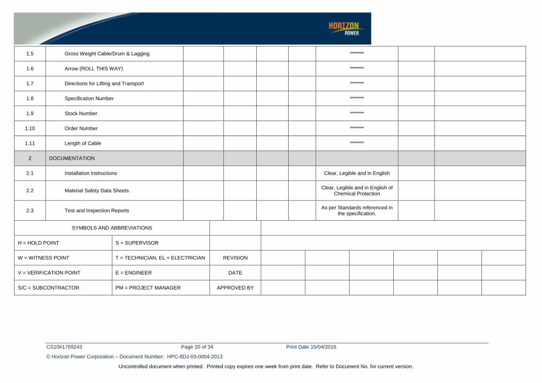
APPENDIX B – QUALITY ASSURANCE (TO BE COMPLETED BY STORES)
DOCUMENT NUMBER HPC-8DJ-03-0004-2013
QUALITY ASSURANCE DM NUMBER
DEVICE DESCRIPTION
LABEL MATERIAL NO.
MV POWER CABLE PURCHASE
ASSET OWNER
ASSET ID/ STOCK NO
MANUFACTURER DIMENSION
ITEM OPERATION/EQUIPMENT/FACILITY DOCUMENT
REF. WHO
CHECKS INITIAL
DATE/ TIME
QUALITY ASSURANCE CRITERIA
PASS Y/N
COMMENTS
1 DRUM LABELLING
1.1 Name of Manufacturer *******
1.2 Week & Year of Manufacture *******
1.3 Manufacturer Drum Trace Number *******
1.4 Cable Information
1.4.1 Number of Cores/Phase conductor size/Material *******
1.4.2 Rated Voltage ____/____ kV
1.4.3 Insulation/Sheath/Protective Covering Materials *******
1.4.4 Cable Metre Mark/Start & Finish Numbers *******
1.4.5 Batch Number *******
1.4.6 Termite/Water Protection *******
CS10#1759243 Page 20 of 34 Print Date 15/04/2016
© Horizon Power Corporation – Document Number: HPC-8DJ-03-0004-2013
Uncontrolled document when printed. Printed copy expires one week from print date. Refer to Document No. for current version.
1.5 Gross Weight Cable/Drum & Lagging *******
1.6 Arrow (ROLL THIS WAY) *******
1.7 Directions for Lifting and Transport *******
1.8 Specification Number *******
1.9 Stock Number *******
1.10 Order Number *******
1.11 Length of Cable *******
2 DOCUMENTATION
2.1 Installation Instructions Clear, Legible and in English
2.2 Material Safety Data Sheets Clear, Legible and in English of
Chemical Protection
2.3 Test and Inspection Reports As per Standards referenced in
the specification.
SYMBOLS AND ABBREVIATIONS
H = HOLD POINT S = SUPERVISOR
W = WITNESS POINT T = TECHNICIAN, EL = ELECTRICIAN REVISION
V = VERIFICATION POINT E = ENGINEER DATE
S/C = SUBCONTRACTOR PM = PROJECT MANAGER APPROVED BY
CS10#1759243 Page 21 of 34 Print Date 15/04/2016
© Horizon Power Corporation – Document Number: HPC-8DJ-03-0004-2013
Uncontrolled document when printed. Printed copy expires one week from print date. Refer to Document No. for current version.
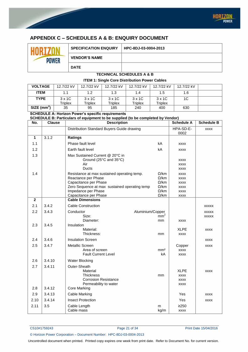
APPENDIX C – SCHEDULES A & B: ENQUIRY DOCUMENT
SPECIFICATION ENQUIRY HPC-8DJ-03-0004-2013
VENDOR’S NAME
DATE
TECHNICAL SCHEDULES A & B
ITEM 1: Single Core Distribution Power Cables
VOLTAGE 12.7/22 kV 12.7/22 kV 12.7/22 kV 12.7/22 kV 12.7/22 kV 12.7/22 kV
ITEM 1.1 1.2 1.3 1.4 1.5 1.6
TYPE 3 x 1C Triplex
3 x 1C Triplex
3 x 1C Triplex
3 x 1C Triplex
3 x 1C Triplex
1C
SIZE (mm2) 35 95 185 240 400 630
SCHEDULE A: Horizon Power’s specific requirements SCHEDULE B: Particulars of equipment to be supplied (to be completed by Vendor)
No. Clause Description Schedule A Schedule B
Distribution Standard Buyers Guide drawing HPA-SD-E-0002
xxxx
1 3.1.2 Ratings
1.1 Phase fault level kA xxxx
1.2 Earth fault level kA xxxx
1.3 Max Sustained Current @ 20°C in Ground (25°C and 35°C) Air Ducts
xxxx xxxx xxxx
1.4 Resistance at max sustained operating temp. Ω/km Reactance per Phase Ω/km Capacitance per Phase Ω/km Zero Sequence at max sustained operating temp Ω/km Impedance per Phase Ω/km Capacitance per Phase Ω/km
xxxx xxxx xxxx xxxx xxxx xxxx
2 Cable Dimensions
2.1 3.4.2 Cable Construction xxxxx
2.2 3.4.3 Conductor Aluminium/Copper Size: mm
2
Diameter: mm
xxxx
xxxxx xxxxx
2.3 3.4.5 Insulation Material: Thickness: mm
XLPE xxxx
xxxx
2.4 3.4.6 Insulation Screen xxxx
2.5 3.4.7 Metallic Screen Area of screen mm² Fault Current Level kA
Copper xxxx xxxx
xxxx
2.6 3.4.10 Water Blocking
2.7 3.4.11 Outer-Sheath Material Thickness mm Corrosion Resistance Permeability to water
XLPE xxxx xxxx xxxx
xxxx
2.8 3.4.12 Core Marking
2.9 3.4.13 Cable Marking Yes xxxx
2.10 3.4.14 Insect Protection Yes xxxx
2.11 3.5 Cable Length m Cable mass kg/m
≥250 xxxx

CS10#1759243 Page 22 of 34 Print Date 15/04/2016
© Horizon Power Corporation – Document Number: HPC-8DJ-03-0004-2013
Uncontrolled document when printed. Printed copy expires one week from print date. Refer to Document No. for current version.
2.12 3.6 Cable Bending Radius (Triplex / 1 core cable) Installation mm Setting mm
xxxx xxxx
2.13 3.7 Cable Pulling Tension kN xxxx
2.14 3.8 Cable End Sealing xxxx
3 Drum Size
4 Flange x Barrel x Width mm Gross mass per standard drum length kg
xxxx xxxx
4 Type test certificate requirements
9.1 Test certificate provided according to AS/NZS 1429.1, Table 3.1
xxxx
5 Manufacturer xxxx
Brand / Catalogue No. / Model xxxx
Country of Manufacture xxxx

CS10#1759243 Page 23 of 34 Print Date 15/04/2016
© Horizon Power Corporation – Document Number: HPC-8DJ-03-0004-2013
Uncontrolled document when printed. Printed copy expires one week from print date. Refer to Document No. for current version.
SPECIFICATION ENQUIRY HPC-8DJ-03-0004-2013
VENDOR’S NAME
DATE
TECHNICAL SCHEDULES A & B
ITEM 2: Single Core Distribution Power Cables
VOLTAGE 19/33 kV 19/33 kV 19/33 kV 19/33 kV 19/33 kV
ITEM 2.1 2.2 2.3 2.4 2.5
TYPE 3 x 1C Triplex
3 x 1C Triplex
3 x 1C Triplex
1C 1C
SIZE (mm2) 50 185 240 630 1000
SCHEDULE A: Horizon Power’s specific requirements SCHEDULE B: Particulars of equipment to be supplied (to be completed by Vendor)
No. Clause Description Schedule A Schedule B
Distribution Standard Buyers Guide drawing HPA-SD-E-0002
xxxx
1 3.1.2 Ratings
1.1 Phase fault level kA xxxx
1.2 Earth fault level kA xxxx
1.3 Max Sustained Current @ 20°C in Ground (25°C and 35°C) Air Ducts
xxxx xxxx xxxx
1.4 Resistance at max sustained operating temp. Ω/km Reactance per Phase Ω/km Capacitance per Phase Ω/km Zero Sequence at max sustained operating temp Ω/km Impedance per Phase Ω/km Capacitance per Phase Ω/km
xxxx xxxx xxxx xxxx xxxx xxxx
2 Cable Dimensions
2.1 3.4.2 Cable Construction xxxxx
2.2 3.4.3 Conductor Aluminium/Copper Size: mm
2
Diameter: mm
xxxx
xxxxx xxxxx
2.3 3.4.5 Insulation Material: Thickness: mm
XLPE xxxx
xxxx
2.4 3.4.6 Insulation Screen xxxx
2.5 3.4.7 Metallic Screen Area of screen mm² Fault Current Level kA
Copper xxxx xxxx
xxxx
2.6 3.4.10 Water Blocking
2.7 3.4.11 Outer-Sheath Material Thickness mm Corrosion Resistance Permeability to water
XLPE xxxx xxxx xxxx
xxxx
2.8 3.4.12 Core Marking
2.9 3.4.13 Cable Marking Yes xxxx
2.10 3.4.14 Insect Protection Yes xxxx
2.11 3.5 Cable Length m Cable mass kg/m
≥250 xxxx

CS10#1759243 Page 24 of 34 Print Date 15/04/2016
© Horizon Power Corporation – Document Number: HPC-8DJ-03-0004-2013
Uncontrolled document when printed. Printed copy expires one week from print date. Refer to Document No. for current version.
2.12 3.6 Cable Bending Radius (Triplex / 1 core cable) Installation mm Setting mm
xxxx xxxx
2.13 3.7 Cable Pulling Tension kN xxxx
2.14 3.8 Cable End Sealing xxxx
3 Drum Size
4 Flange x Barrel x Width mm Gross mass per standard drum length kg
xxxx xxxx
4 Type test certificate requirements
9.1 Test certificate provided according to AS/NZS 1429.1, Table 3.1
xxxx
5 Manufacturer xxxx
Brand / Catalogue No. / Model xxxx
Country of Manufacture xxxx

CS10#1759243 Page 25 of 34 Print Date 15/04/2016
© Horizon Power Corporation – Document Number: HPC-8DJ-03-0004-2013
Uncontrolled document when printed. Printed copy expires one week from print date. Refer to Document No. for current version.
APPENDIX D – SCHEDULE C: COMPLIANCE DOCUMENT
The Vendor shall indicate below whether this offer is fully compliant with the nominated clause in this Specification. A YES shall ONLY be indicated if the offer is 100% compliant with the relevant Clause. If NO is indicated and supporting documents are submitted, then mark the ATT box with the attachment number
CLAUSE NUMBER YES NO ATT.
1. SCOPE
2. NORMATIVE REFERENCES 2.1 Standards 2.2 Definitions and Abbreviations 2.2.1 Definitions 2.2.2 Abbreviations 2.3 Drawings
3 REQUIREMENTS 3.1 Power System Particulars
3.1.1 Rated Voltages 3.1.2 Design Fault Levels 3.1.3 Maximum Conductor Temperatures 3.1.4 Nominal System Frequency 3.1.5 System Insulation Levels 3.2 Service Conditions
3.2.1 Environmental Conditions 3.2.2 Operating Conditions 3.3 Description of Cable 3.4 Materials and Construction
3.4.1 General 3.4.2 Cable Construction 3.4.3 Conductor 3.4.4 Conductor Screen 3.4.5 Insulation
3.4.5.1 Material 3.4.5.2 Thickness 3.4.6 Insulation Screen 3.4.7 Metallic Screen 3.5.8 Laying Up 3.4.9 Bedding / Fillers 3.4.10 Water Blocking 3.4.11 Outer Sheath 3.4.12 Core Marking 3.4.13 Cable Markings 3.4.14 Protection from Insect Attack 3.5 Cable Length

CS10#1759243 Page 26 of 34 Print Date 15/04/2016
© Horizon Power Corporation – Document Number: HPC-8DJ-03-0004-2013
Uncontrolled document when printed. Printed copy expires one week from print date. Refer to Document No. for current version.
CLAUSE NUMBER YES NO ATT.
3.6 Cable Bending Radius 3.7 Cable Pulling Tension 3.8 Cable-end Sealing 4 CABLE DRUMS
4.1 Timber Drums 4.2 Steel Drums 4.3 Drum Marking
5. STORAGE
6. RELIABILITY
7. SAFETY
8. ENVIRONMENTAL CONDITIONS 9. TESTS
9.1 Test Requirements 9.1.1 Type Tests 9.1.2 Routine Tests
10. DOCUMENTATION AND SAMPLES 10.1 Type Test Certificates/Reports 10.2 Samples
10.2.1 Tests Samples 10.2.2 Display Samples

CS10#1759243 Page 27 of 34 Print Date 15/04/2016
© Horizon Power Corporation – Document Number: HPC-8DJ-03-0004-2013
Uncontrolled document when printed. Printed copy expires one week from print date. Refer to Document No. for current version.
APPENDIX E – SCHEDULE D: DEPARTURES FROM TECHNICAL SPECIFICATION
The Vendor shall nominate the Clause and describe the departure:
CLAUSE NO DEPARTURE
CS10#1759243 Page 28 of 34 Print Date 15/04/2016
© Horizon Power Corporation – Document Number: HPC-8DJ-03-0004-2013
Uncontrolled document when printed. Printed copy expires one week from print date. Refer to Document No. for current version.
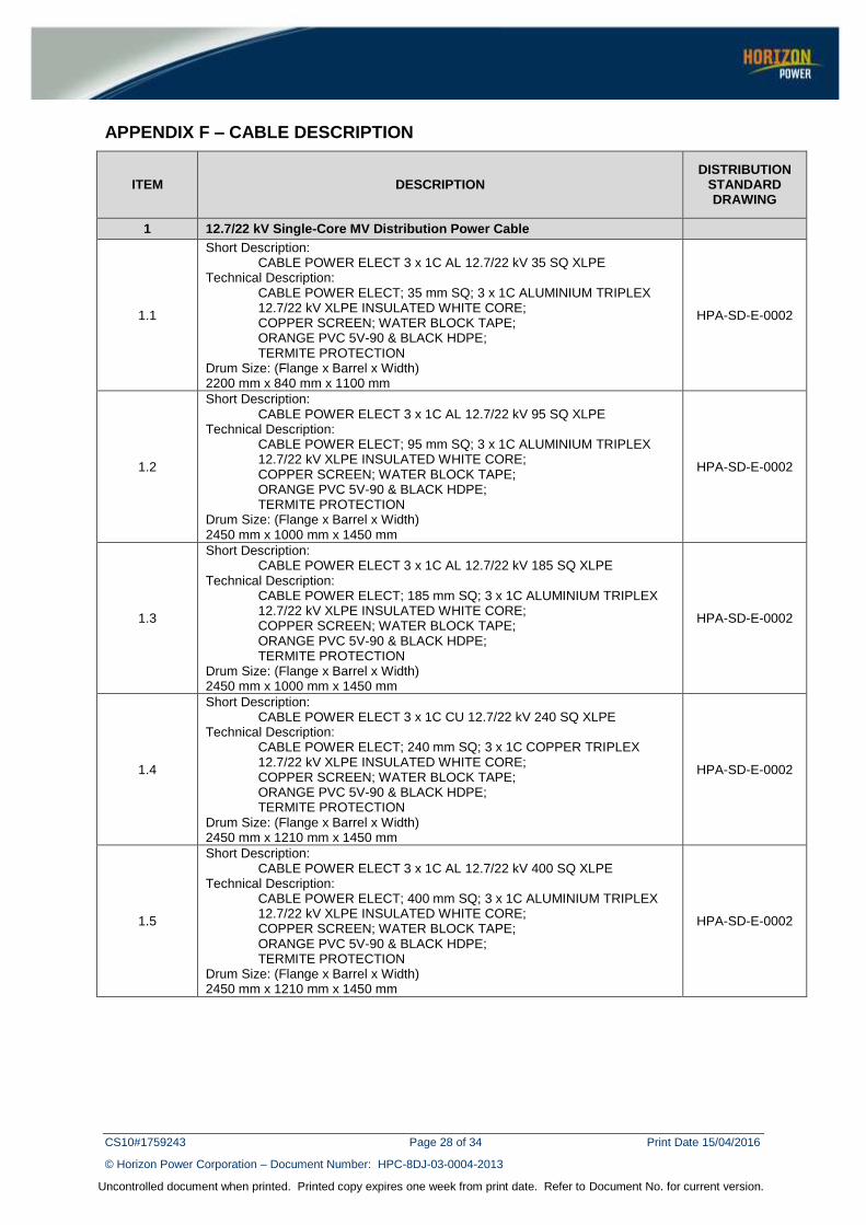
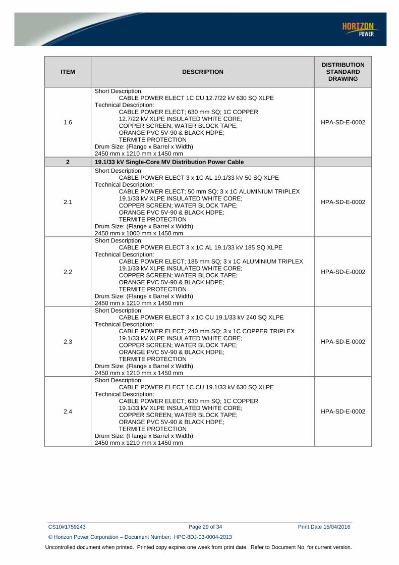
APPENDIX F – CABLE DESCRIPTION
ITEM DESCRIPTION DISTRIBUTION
STANDARD DRAWING
1 12.7/22 kV Single-Core MV Distribution Power Cable
1.1
Short Description: CABLE POWER ELECT 3 x 1C AL 12.7/22 kV 35 SQ XLPE Technical Description: CABLE POWER ELECT; 35 mm SQ; 3 x 1C ALUMINIUM TRIPLEX 12.7/22 kV XLPE INSULATED WHITE CORE; COPPER SCREEN; WATER BLOCK TAPE; ORANGE PVC 5V-90 & BLACK HDPE; TERMITE PROTECTION Drum Size: (Flange x Barrel x Width) 2200 mm x 840 mm x 1100 mm
HPA-SD-E-0002
1.2
Short Description: CABLE POWER ELECT 3 x 1C AL 12.7/22 kV 95 SQ XLPE Technical Description: CABLE POWER ELECT; 95 mm SQ; 3 x 1C ALUMINIUM TRIPLEX 12.7/22 kV XLPE INSULATED WHITE CORE; COPPER SCREEN; WATER BLOCK TAPE; ORANGE PVC 5V-90 & BLACK HDPE; TERMITE PROTECTION Drum Size: (Flange x Barrel x Width) 2450 mm x 1000 mm x 1450 mm
HPA-SD-E-0002
1.3
Short Description: CABLE POWER ELECT 3 x 1C AL 12.7/22 kV 185 SQ XLPE Technical Description: CABLE POWER ELECT; 185 mm SQ; 3 x 1C ALUMINIUM TRIPLEX 12.7/22 kV XLPE INSULATED WHITE CORE; COPPER SCREEN; WATER BLOCK TAPE; ORANGE PVC 5V-90 & BLACK HDPE; TERMITE PROTECTION Drum Size: (Flange x Barrel x Width) 2450 mm x 1000 mm x 1450 mm
HPA-SD-E-0002
1.4
Short Description: CABLE POWER ELECT 3 x 1C CU 12.7/22 kV 240 SQ XLPE Technical Description: CABLE POWER ELECT; 240 mm SQ; 3 x 1C COPPER TRIPLEX 12.7/22 kV XLPE INSULATED WHITE CORE; COPPER SCREEN; WATER BLOCK TAPE; ORANGE PVC 5V-90 & BLACK HDPE; TERMITE PROTECTION Drum Size: (Flange x Barrel x Width) 2450 mm x 1210 mm x 1450 mm
HPA-SD-E-0002
1.5
Short Description: CABLE POWER ELECT 3 x 1C AL 12.7/22 kV 400 SQ XLPE Technical Description: CABLE POWER ELECT; 400 mm SQ; 3 x 1C ALUMINIUM TRIPLEX 12.7/22 kV XLPE INSULATED WHITE CORE; COPPER SCREEN; WATER BLOCK TAPE; ORANGE PVC 5V-90 & BLACK HDPE; TERMITE PROTECTION Drum Size: (Flange x Barrel x Width) 2450 mm x 1210 mm x 1450 mm
HPA-SD-E-0002
CS10#1759243 Page 29 of 34 Print Date 15/04/2016
© Horizon Power Corporation – Document Number: HPC-8DJ-03-0004-2013
Uncontrolled document when printed. Printed copy expires one week from print date. Refer to Document No. for current version.
ITEM DESCRIPTION DISTRIBUTION
STANDARD DRAWING
1.6
Short Description: CABLE POWER ELECT 1C CU 12.7/22 kV 630 SQ XLPE Technical Description: CABLE POWER ELECT; 630 mm SQ; 1C COPPER 12.7/22 kV XLPE INSULATED WHITE CORE; COPPER SCREEN; WATER BLOCK TAPE; ORANGE PVC 5V-90 & BLACK HDPE; TERMITE PROTECTION Drum Size: (Flange x Barrel x Width) 2450 mm x 1210 mm x 1450 mm
HPA-SD-E-0002
2 19.1/33 kV Single-Core MV Distribution Power Cable
2.1
Short Description: CABLE POWER ELECT 3 x 1C AL 19.1/33 kV 50 SQ XLPE Technical Description: CABLE POWER ELECT; 50 mm SQ; 3 x 1C ALUMINIUM TRIPLEX 19.1/33 kV XLPE INSULATED WHITE CORE; COPPER SCREEN; WATER BLOCK TAPE; ORANGE PVC 5V-90 & BLACK HDPE; TERMITE PROTECTION Drum Size: (Flange x Barrel x Width) 2450 mm x 1000 mm x 1450 mm
HPA-SD-E-0002
2.2
Short Description: CABLE POWER ELECT 3 x 1C AL 19.1/33 kV 185 SQ XLPE Technical Description: CABLE POWER ELECT; 185 mm SQ; 3 x 1C ALUMINIUM TRIPLEX 19.1/33 kV XLPE INSULATED WHITE CORE; COPPER SCREEN; WATER BLOCK TAPE; ORANGE PVC 5V-90 & BLACK HDPE; TERMITE PROTECTION Drum Size: (Flange x Barrel x Width) 2450 mm x 1210 mm x 1450 mm
HPA-SD-E-0002
2.3
Short Description: CABLE POWER ELECT 3 x 1C CU 19.1/33 kV 240 SQ XLPE Technical Description: CABLE POWER ELECT; 240 mm SQ; 3 x 1C COPPER TRIPLEX 19.1/33 kV XLPE INSULATED WHITE CORE; COPPER SCREEN; WATER BLOCK TAPE; ORANGE PVC 5V-90 & BLACK HDPE; TERMITE PROTECTION Drum Size: (Flange x Barrel x Width) 2450 mm x 1210 mm x 1450 mm
HPA-SD-E-0002
2.4
Short Description: CABLE POWER ELECT 1C CU 19.1/33 kV 630 SQ XLPE Technical Description: CABLE POWER ELECT; 630 mm SQ; 1C COPPER 19.1/33 kV XLPE INSULATED WHITE CORE; COPPER SCREEN; WATER BLOCK TAPE; ORANGE PVC 5V-90 & BLACK HDPE; TERMITE PROTECTION Drum Size: (Flange x Barrel x Width) 2450 mm x 1210 mm x 1450 mm
HPA-SD-E-0002

CS10#1759243 Page 30 of 34 Print Date 15/04/2016
© Horizon Power Corporation – Document Number: HPC-8DJ-03-0004-2013
Uncontrolled document when printed. Printed copy expires one week from print date. Refer to Document No. for current version.
ITEM DESCRIPTION DISTRIBUTION
STANDARD DRAWING
2.5
Short Description: CABLE POWER ELECT 1C AL 19.1/33 kV 1000 SQ XLPE Technical Description: CABLE POWER ELECT; 1000 mm SQ; 1C ALUMINIUM 19.1/33 kV XLPE INSULATED WHITE CORE; COPPER SCREEN; WATER BLOCK TAPE; ORANGE PVC 5V-90 & BLACK HDPE; TERMITE PROTECTION Drum Size: (Flange x Barrel x Width) 2450 mm x 1210 mm x 1450 mm
HPA-SD-E-0002

CS10#1759243 Page 31 of 34 Print Date 15/04/2016
© Horizon Power Corporation – Document Number: HPC-8DJ-03-0004-2013
Uncontrolled document when printed. Printed copy expires one week from print date. Refer to Document No. for current version.
APPENDIX G – STANDARD TIMBER DRUM DIMENSIONS
Construction Details for Standard Timber Drums with Barrel-end Supports (2 to 6 Tonne)
Drum reference number
(arranged in ascending order of barrel
diameter)
Flange details Barrel details Overall drum width (excl.
bolt projections)
(mm)
Spindle hole diameter
(mm) Diameter (mm)
Nominal thickness
(mm)
Diameter (mm)
Internal width (mm)
End support minimum thickness
(mm)
Stretchers Number of diagonal
crow braces
Bolts Minimum bore
thickness (mm)
Number of intermediate
supports
Square washers (or equivalent
round washers) Number Size
(mm) Number Minimum diameter
(mm) 700 / 400 / 300 700 35 400 300 25 3 100 × 35 3 8 19 40 × 4 370 60 700 / 400 / 400 700 35 400 400 25 3 100 × 35 3 8 19 40 × 4 470 60 800 / 400 / 350 800 35 400 350 25 3 100 × 35 3 8 19 40 × 4 420 60 800 / 400 / 450 800 35 400 450 25 3 100 × 35 3 8 19 40 × 4 520 60 900 / 500 / 500 900 45 500 500 35 4 100 × 35 4 12 32 50 × 4 590 60
900 / 500 / 600 900 45 500 600 35 4 100 × 35 4 12 32 50 × 4 690 60 1000 / 500 / 550 1000 45 500 550 35 4 100 × 35 4 12 32 50 × 4 640 95 1000 / 700 / 650 1000 45 700 650 35 4 100 × 35 4 12 32 50 × 4 740 95 1100 / 600 / 650 1100 45 600 650 35 4 100 × 35 4 12 32 50 × 4 740 95 1200 / 600 / 650 1200 60 600 650 35 4 100 × 35 4 12 32 50 × 4 770 95 1200 / 600 / 800 1200 60 600 800 35 4 100 × 35 4 12 32 50 × 4 920 95 1200 / 800 / 550 1200 60 800 550 35 5 100 × 35 5 12 32 50 × 4 670 95 1200 / 800 / 700 1200 60 800 700 35 5 100 × 35 5 12 32 50 × 4 820 95
1300 / 900 / 800 1300 70 900 800 35 5 100 × 35 5 12 32 75 × 6 940 95 1400 / 700 / 750 1400 70 700 750 35 4 200 × 35 4 12 32 75 × 6 890 95 1400 / 1000 / 900 1400 70 1000 900 35 6 200 × 35 6 16 32 75 × 6 1040 95 1600 / 800 / 750 1600 70 800 750 35 5 200 × 35 5 16 32 75 × 6 890 95 1600 / 1100 / 850 1600 70 1100 850 35 6 200 × 35 6 16 32 75 × 6 990 95 1600 / 1100 / 1100 1600 70 1100 1100 35 6 200 × 35 6 16 32 1 75 × 6 1240 95 1600 / 800 / 950 1600 70 800 800 35 5 200 × 35 5 16 32 1 75 × 6 1090 95
1800 / 900 / 950 1800 70 900 950 35 5 200 × 35 5 16 32 1 75 × 6 1090 110 1800 / 900 / 1200 1800 70 900 1200 35 5 200 × 35 5 12 32 2 75 × 6 1340 110 1800 / 1200 / 1000 1800 70 1200 1000 35 6 200 × 35 6 16 32 1 75 × 6 1140 110
2000 / 1000 / 950 2000 70 1000 950 35 6 200 × 35 6 16 32 1 75 × 6 1090 110 2000 / 1000 / 1200 2000 70 1000 1200 35 6 200 × 35 6 16 32 2 75 × 6 1340 110 2000 / 1400 / 1150 2000 70 1400 1150 35 8 200 × 35 4 8 16 32 1 75 × 6 1290 110 2200 / 1100 / 950 2200 70 1100 950 35 6 200 × 35 4 6 16 32 1 75 × 6 1090 110 2200 / 1100 / 1300 2200 70 1100 1300 35 6 200 × 35 4 6 16 32 2 75 × 6 1440 110 2200 / 1500 / 1300 2200 70 1500 1300 35 8 200 × 35 4 8 16 32 2 75 × 6 1440 110
2400 / 1200 / 1400 2400 95 1200 1400 35 6 200 × 35 4 6 16 32 2 75 × 6 1590 110 2400 / 1400 / 1200 2400 95 1400 1200 35 8 200 × 35 4 8 16 32 2 75 × 6 1390 110 2400 / 1400 / 1400 2400 95 1400 1400 35 8 200 × 35 4 8 16 32 2 75 × 6 1590 110 2600 / 1400 / 1300 2600 95 1400 1300 35 12 200 × 35 6 12 16 32 2 75 × 6 1490 110 2600 / 1600 / 1300 2600 95 1600 1300 35 12 200 × 35 6 12 16 32 2 75 × 6 1490 110

CS10#1759243 Page 32 of 34 Print Date 15/04/2016
© Horizon Power Corporation – Document Number: HPC-8DJ-03-0004-2013
Uncontrolled document when printed. Printed copy expires one week from print date. Refer to Document No. for current version.
2800 / 1600 / 1200 2800 110 1600 1200 35 12 200 × 35 6 12 22 32 2 75 × 6 1420 110 2800 / 1800 / 1400 2800 110 1800 1400 35 12 200 × 35 6 12 22 32 2 75 × 6 1620 110 3000 / 1600 / 1200 3000 110 1600 1200 35 12 200 × 35 6 12 22 32 2 75 × 6 1420 110 3000 / 1800 / 1400 3000 110 1800 1400 35 12 200 × 35 6 12 22 32 2 75 × 6 1620 110

CS10#1759243 Page 33 of 34 Print Date 15/04/2016
© Horizon Power Corporation – Document Number: HPC-8DJ-03-0004-2013
Uncontrolled document when printed. Printed copy expires one week from print date. Refer to Document No. for current version.
APPENDIX H – SCHEDULE E: TEST REPORT REQUIREMENTS FOR CHEMICAL PROTECTION
An investigation and test report shall be submitted for cables offered with chemical protection against insect attack. The report shall demonstrate and address (but not limited to) the items listed below, including any further testing undertaken on the chemically treated cable ONLY. Vendors shall state reasons and justifications for all comments made to qualify their response.
Horizon Power will evaluate to its satisfaction the information and make a determination to accept or reject the cables offered with chemical protection against insect attack. If rejected, the Vendor shall offer alternative cables with mechanical protection that may include (and not limited to) Polyarnide coverings or metallic tapes to achieve the required protection from insect attack.
No Criteria Submitted (Y/N)
1 Process of Manufacture and Product Stability
2 Quality assurance and consistency of chemical in cable
3 Accelerated aging tests
4 Surface blooming of chemical
5 Tests to show how much chemical is adsorbed by different types of soil particles (low and high pH) and the quantity of chemical that may flow into wetlands / rivers etc.
6 Leachate tests with different pH fluids (leach rate per day) declaring the amount of dissolved chemical (free flowing in water) and what reaction the available chemical will have on aquatic organisms.
7 Impact of chemical/vapour by-products during power cable failure
8 Efficacy tests of the chemical in the cable against insect attack (differing chemical concentrations)
9 Behaviour of the chemical and life-span whilst in the cable due to heat, UV, water of varying pH and other expected exposure factors
10 Mechanism by which chemical protects cable from insect attack and any dependencies
11 OH&S requirements for handling, installation, jointing (flame brushing), disposing and other related items
12 Exposure mechanisms of chemical from cable, including quantitative impact on humans, land and aquatic organisms
13 Dangerous goods classification and shipping requirements
14 Impact on organic growers
15
NICNAS (National Industrial Chemicals Notification and Assessment Scheme) and APVMA (Australian Pesticides and Veterinary Medicines Authority) approvals required
16 Comparative studies with PVC and Polyamide techniques
17 Any declared restrictions relating to use of the chemically treated cable
18 Any type of surface residue is not acceptable
Additional Vendor Information

CS10#1759243 Page 34 of 34 Print Date 15/04/2016
© Horizon Power Corporation – Document Number: HPC-8DJ-03-0004-2013
Uncontrolled document when printed. Printed copy expires one week from print date. Refer to Document No. for current version.
APPENDIX I – SPECIFICATION DRAWINGS


![GLOBAL STANDARD Page 1 of 52 GSM001 MV RMU … RMU WITH SWITCH-DISCONNECTOR Rev. 00 10/07/2014 Rated voltage [kV] 24 36 Rated insulation level . MV RMU WITH SWITCH-DISCONNECTOR GSM001](https://static.fdocuments.in/doc/165x107/5b0741567f8b9a5c308e195d/global-standard-page-1-of-52-gsm001-mv-rmu-rmu-with-switch-disconnector-rev-00.jpg)