TECH SPEC - Panablock Spec 4.pdf · 3 traffic, subgrade soil strength, and pavement materials. The...
8
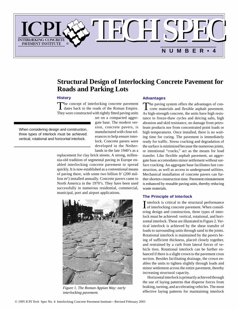
© 1995 ICPI Tech Spec No. 4 Interlocking Concrete Pavement Institute—Revised February 2003 Figure 1. The Roman Appian Way: early interlocking pavement. Structural Design of Interlocking Concrete Pavement for Roads and Parking Lots History T he concept of interlocking concrete pavement dates back to the roads of the Roman Empire. They were constructed with tightly fitted paving units set on a compacted aggre- gate base. The modern ver- sion, concrete pavers, is manufactured with close tol- erances to help ensure inter- lock. Concrete pavers were developed in the Nether- lands in the late 1940’s as a replacement for clay brick streets. A strong, millen- nia-old tradition of segmental paving in Europe en- abled interlocking concrete pavement to spread quickly. It is now established as a conventional means of paving there, with some two billion ft 2 (200 mil- lion m 2 ) installed annually. Concrete pavers came to North America in the 1970’s. They have been used successfully in numerous residential, commercial, municipal, port and airport applications. Advantages T he paving system offers the advantages of con- crete materials and flexible asphalt pavement. As high-strength concrete, the units have high resis- tance to freeze-thaw cycles and deicing salts, high abrasion and skid resistance, no damage from petro- leum products nor from concentrated point loads or high temperatures. Once installed, there is no wait- ing time for curing. The pavement is immediately ready for traffic. Stress cracking and degradation of the surface is minimized because the numerous joints, or intentional “cracks,” act as the means for load transfer. Like flexible asphalt pavement, an aggre- gate base accomodates minor settlement without sur- face cracking. An aggregate base facilitates fast con- struction, as well as access to underground utilities. Mechanical installation of concrete pavers can fur- ther shorten construction time. Pavement reinstatement is enhanced by reusable paving units, thereby reducing waste materials. The Principle of Interlock I nterlock is critical to the structural performance of interlocking concrete pavement. When consid- ering design and construction, three types of inter- lock must be achieved: vertical, rotational, and hori- zontal interlock. These are illustrated in Figure 2. Ver- tical interlock is achieved by the shear transfer of loads to surrounding units through sand in the joints. Rotational interlock is maintained by the pavers be- ing of sufficient thickness, placed closely together, and restrained by a curb from lateral forces of ve- hicle tires. Rotational interlock can be further en- hanced if there is a slight crown to the pavement cross section. Besides facilitating drainage, the crown en- ables the units to tighten slightly through loads and minor settlement across the entire pavement, thereby increasing structural capacity. Horizontal interlock is primarily achieved through the use of laying patterns that disperse forces from braking, turning, and accelerating vehicles. The most effective laying patterns for maintaining interlock When considering design and construction, three types of interlock must be achieved: vertical, rotational and horizontal interlock. TECH SPEC TECH SPEC NUMBER•4
Transcript of TECH SPEC - Panablock Spec 4.pdf · 3 traffic, subgrade soil strength, and pavement materials. The...
© 1995 ICPI Tech Spec No. 4 Interlocking Concrete Pavement Institute—Revised February 2003
Figure 1. The Roman Appian Way: earlyinterlocking pavement.
Structural Design of Interlocking Concrete Pavement forRoads and Parking LotsHistory
The concept of interlocking concrete pavementdates back to the roads of the Roman Empire.
They were constructed with tightly fitted paving unitsset on a compacted aggre-gate base. The modern ver-sion, concrete pavers, ismanufactured with close tol-erances to help ensure inter-lock. Concrete pavers weredeveloped in the Nether-lands in the late 1940’s as a
replacement for clay brick streets. A strong, millen-nia-old tradition of segmental paving in Europe en-abled interlocking concrete pavement to spreadquickly. It is now established as a conventional meansof paving there, with some two billion ft2 (200 mil-lion m2) installed annually. Concrete pavers came toNorth America in the 1970’s. They have been usedsuccessfully in numerous residential, commercial,municipal, port and airport applications.
Advantages
The paving system offers the advantages of con-crete materials and flexible asphalt pavement.
As high-strength concrete, the units have high resis-tance to freeze-thaw cycles and deicing salts, highabrasion and skid resistance, no damage from petro-leum products nor from concentrated point loads orhigh temperatures. Once installed, there is no wait-ing time for curing. The pavement is immediatelyready for traffic. Stress cracking and degradation ofthe surface is minimized because the numerous joints,or intentional “cracks,” act as the means for loadtransfer. Like flexible asphalt pavement, an aggre-gate base accomodates minor settlement without sur-face cracking. An aggregate base facilitates fast con-struction, as well as access to underground utilities.Mechanical installation of concrete pavers can fur-ther shorten construction time. Pavement reinstatementis enhanced by reusable paving units, thereby reducingwaste materials.
The Principle of Interlock
Interlock is critical to the structural performanceof interlocking concrete pavement. When consid-
ering design and construction, three types of inter-lock must be achieved: vertical, rotational, and hori-zontal interlock. These are illustrated in Figure 2. Ver-tical interlock is achieved by the shear transfer ofloads to surrounding units through sand in the joints.Rotational interlock is maintained by the pavers be-ing of sufficient thickness, placed closely together,and restrained by a curb from lateral forces of ve-hicle tires. Rotational interlock can be further en-hanced if there is a slight crown to the pavement crosssection. Besides facilitating drainage, the crown en-ables the units to tighten slightly through loads andminor settlement across the entire pavement, therebyincreasing structural capacity.
Horizontal interlock is primarily achieved throughthe use of laying patterns that disperse forces frombraking, turning, and accelerating vehicles. The mosteffective laying patterns for maintaining interlock
When considering design and construction,three types of interlock must be achieved:vertical, rotational and horizontal interlock.
TECH SPEC TECH SPECN U M B E R • 4

2
Figure 3. Layingpatterns for
vehicular traffic.
are herringbone patterns. Testing has shown thatthese patterns offer greater structural capacity andresistance to lateral movement than other layingpatterns (1, 2, 3). Therefore, herringbone patterns arerecommended in areas subject to vehicular traffic.See Figure 3. Stable edge restraints such as curbs areessential. They maintain horizontal interlock whilethe units are subject to repeated lateral loads fromvehicle tires. ICPI Tech Spec 3, Edge Restraints forInterlocking Concrete Pavements offers guidance onthe selection and detailing of edge restraints for arange of applications.
Typical Pavement Designand Construction
Figure 4 illustrates typical schematic cross sec-tions for interlocking concrete pavement. Both
the base and subbase are compacted aggregate. Manypavements for city and residential uses do not re-
quire an aggregate subbase except for very heavyuse, or over a weak soil subgrade. In these situa-tions it may be more economical to use asphalt orcement stabilized base layers. They are often placedover a subbase layer of unbound compacted aggre-gate.
Construction is covered in ICPI Tech Spec 2,Construction of Interlocking Concrete Pavement.The steps for preparing the soil subgrade and basematerials are similar to those required for flexibleasphalt pavements. After the base surface is built tospecified elevations and surface tolerances, beddingsand is screeded in an even layer, typically 1–11/2 in.(25–40 mm) thick. The units are placed, manually ormechanically, on the smooth bedding sand, con-strained by stationary edge restraints.
The pavers are vibrated with a high frequencyplate vibrator. This action forces sand into the bot-tom of the joints of the pavers and begins compaction
Figure 2. Types of interlock: vertical, rotational, horizontal.

3
traffic, subgrade soil strength, and pavementmaterials. The design engineer selects valuesrepresenting attributes of these factors. Thevalues can be very approximate correlationsand qualitative assumptions. Each factor, how-ever, can be measured accurately with detailedengineering studies and extensive laboratorytesting. As more detailed information is ob-tained about each factor, the reliability of thedesign will increase.
The effort and cost in obtaining informa-tion about each should be consistent with theimportance of the pavement. A major thor-oughfare should receive more analysis of thesoil subgrade and traffic mix than a residentialstreet. Furthermore, the degree of analysisand engineering should increase as thesubgrade strength decreases and as the antici-pated traffic level increases. In other words,pavements for high volume traffic over weaksoils should have the highest degree of analy-sis of each factor as is practical.
Environment—Moisture and temperaturesignificantly affect pavement. As moisture inthe soil or base increases, the load bearingcapacity of the soil or the strength of the basedecreases. Moisture causes differential heav-ing and swelling of certain soils, as well.Temperature can affect the load bearing ca-pacity of pavements, particularly asphalt sta-
bilized layers. The combined effect of freezing tem-peratures and moisture can lead to the two detrimen-tal effects. First, expansion of the water during freez-ing can cause the pavement to heave. Second, thestrength of the pavement materials can be reduced bythawing.
These detrimental effects can be reduced or elim-inated one of three ways. Moisture can be kept fromentering the pavement base and soil. Moisture can beremoved before it has a chance to weaken the pave-ment. Pavement materials can be used to resist mois-ture and movement from swelling or frost. Limitedconstruction budgets often do not allow completeprotection against the effects of moisture and freeze-thaw. Consequently, their effects should be mitigatedto the highest extent allowed by the available budgetand materials.
In this design procedure, the effects of moistureand frost are part of characterizing of the strength ofsubgrade soil and pavement materials. Subjectivedescriptions of drainage quality and moisture condi-tions influence design strength values for sub-grade soils and unbound granular materials. Inaddition, if freeze-thaw exists, then soil subgradestrength is reduced according to the degree of itsfrost susceptibility.
Traffic—When pavement is trafficked, it receiveswear or damage. The amount of damage depends onthe weight of the vehicles and the number of expectedpasses over a given period of time. The period of time,
of the bedding sand. Sand is then spread and sweptinto the joints, and the pavers are compacted againuntil the joints are filled. Complete compaction ofthe sand and slight settlement of the pavers tightensthem. During compaction, the pavement is trans-formed from a loose collection of pavers to aninterlocking system capable of spreading verticalloads horizontally. This occurs through shear forcesin the joints.
Structural Design Procedure
The load distribution and failure modes offlexible asphalt and interlocking concrete pave-
ment are very similar: permanent deformation fromrepetitive loads. Since failure modes are similar, asimplified procedure of the method is adapted fromReference 4 and the American Association of StateHighway and Transportation Officials (AASHTO)1993 Guide for Design of Pavement Structures (5).The following structural design procedure is forroads and parking lots. Design for heavy duty pave-ments such as port and airport pavements is coveredin ICPI manuals entitled, Port and Industrial Pave-ment Design for Concrete Pavers, and Airfield Pave-ment Design with Concrete Pavers.
Design Considerations
The evaluation of four factors and their inter-active effects will determine the final pavement
thickness and material. These include environment,
Figure 4. Typical schematic cross sections.
Concrete Pavers Joint Sand
EdgeRestraint/
Curb
Compacted UnboundAggregate Sub-Base
Compacted Subgrade Soil
Compacted Cement orAsphalt Treated Base
BeddingSand
Concrete Pavers Joint Sand
EdgeRestraint/
Curb
Compacted UnboundAggregate Sub-Base
Compacted Subgrade Soil
Compacted UnboundAggregate Base
BeddingSand
(A) Unbound Base/Subbase
(B) Cement or Asphalt Treated Base

4
or design life, is usually20 years. Predicted traf-fic over the life of thepavement is an estimateof various vehicle loads,axle and wheel configu-rations, and the numberof loads. The actualamount of traffic loadscan often exceed the pre-dicted loads. There-fore,engineering judge-ment is required in esti-mating expected sourcesof traffic and loads wellinto the future.
Damage to pavementresults from a multitudeof axle loads from cars,vans, light trucks, busesand tractor-trailers. Inorder to more easily pre-dict the damage, all ofthe various axle loads areexpressed as damagefrom an equivalent stan-dard axle load. In otherwords, the combineddamaging effects of vari-ous axle loads are equatedto the damaging effect of18-kip (80 kN) equiva-lent single axle load(EALs) repetitions. Dam-age factors for other axleloads are shown in Table1. For example, the tableshows that a single axleload of 38-kip (169 kN)would cause the samepavement damage asapproximately 30 passesof an 18-kip (80 kN)single axle.
For pavements carrying many different kinds ofvehicles, greater study is needed to obtain the expecteddistribution of axle loads within the design period. Ifno detailed traffic information is available, Table 2 canbe used for general guidance by listing typical EALs asa function of road class. In some situations, the de-signer cannot know the expected traffic in five, ten orfifteen years into the future. Therefore, the reliability(degree of conservatism) of the engineer’s predictionscan be modified as follows:
Adjusted EALs = FR x EALs (estimated or from
Table 2) where FR is the reliability factor. Recom-
mended reliability factors by road class are also givenin Table 2, along with the corresponding adjustedEALs for use in the design.
In some residential development projects, inter-
locking concrete pavement streets are constructedfirst and then housing is built. Axle loads fromconstruction-related truck traffic should be factoredinto the base thickness design. The loads can besubstantial compared to the lighter loads from auto-mobiles after construction is complete.
Soil Subgrade Support—The strength of thesoil subgrade has the greatest effect in determiningthe total thickness of the interlocking concrete pave-ment. When feasible, resilient modulus or soakedCalifornia Bearing Ratio (CBR) laboratory testsshould be conducted on the typical subgrade soil toevaluate its strength. These tests should be con-ducted at the most probable field conditions ofdensity and moisture that will be anticipated duringthe design life of the pavement. CBR tests are de-scribed in ASTM D 1883 (6) or AASHTO T-193 (7).
In the absence of laboratory tests, typical resilientmodulus (M
r) values have been assigned to each soil
type defined in the United Soil Classification Sys-tem (USCS), per ASTM D 2487 (6), or AASHTOsoil classification systems (see Tables 3 and 4).Three modulus values are provided for each USCSor AASHTO soil type, depending on the anticipatedenvironmental and drainage conditions at the site.
Guidelines for selecting the appropriate Mr value
are summarized in Table 5. Each soil type in Tables3 and 4 has also been assigned a reduced M
r value
(far right column) for use only when frost action is adesign consideration.
Compaction of the subgrade soil during construc-tion should be at least 98% of AASHTO T-99 orASTM D 698 for cohesive (clay) soils and at least98% of AASHTO T-180 or ASTM D 1557 forcohesionless (sandy and gravelly) soils. The highercompaction standards described in T-180 or D 1557are preferred. The effective depth of compaction forall cases should be at least the top 12 inches (300mm). Soils having an M
r of 4,500 psi (31 MPa) or
less (CBR 3% or less) should be evaluated for eitherreplacement with a material with higher bearingstrength, installation of an aggregate subbase cap-ping layer, improvement by stabilization, or useof geotextiles.
Pavement Materials—The type, strength andthickness of all available paving materials should beestablished. Crushed aggregate bases, or stabilizedbases used in highway construction are generallysuitable for interlocking concrete pavement. Moststates, provinces and municipalities have materialand construction standards for these bases. Ifnone are available, then the standards found inASTM D 2940 (6) may be used. Minimum recom-mended strength requirements for unbound aggre-gate bases should be CBR = 80% and CBR = 30%for subbases.
For unbound aggregate base material, the Plastic-ity Index should be no greater than 6; the LiquidLimit limited to 25; and compaction should be atleast 98% of AASHTO T-180 density. For unbound
2 (9) 0.0002 10 (44) 0.016 (27) 0.01 14 (62) 0.0310 (44) 0.08 18 (80) 0.0814 (62) 0.34 22 (98) 0.1718 (80) 1.00 26 (115) 0.3422 (98) 2.44 30 (133) 0.6326 (115) 5.21 34 (157) 1.0730 (133) 10.03 38 (169) 1.7534 (157) 17.87 42 (186) 2.7538 (169) 29.95 46 (204) 4.11
TABLE 1Axle Load Damage Factors
TABLE 2Typical Design EALs
Single Axle Tandem AxleKips (kN) Damage Factor Kips (kN) Damage Factor
Road ClassEALs*
(millions)Design EALs*
(millions)Reliability
Factor
Arterial orMajor Streets
Urban 7.5 3.775 28.4Rural 3.6 2.929 10.6
Major CollectorsUrban 2.8 2.929 8.3Rural 1.5 2.390 3.5
Minor CollectorsUrban 1.3 2.390 3.0Rural 0.55 2.390 1.3
Commercial/Multi-Family Locals
Urban 0.43 2.010 0.84Rural 0.28 2.010 0.54
*Assume a 20 year design life.
5
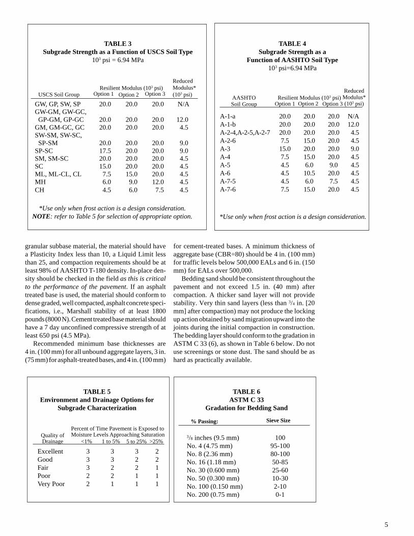
for cement-treated bases. A minimum thickness ofaggregate base (CBR=80) should be 4 in. (100 mm)for traffic levels below 500,000 EALs and 6 in. (150mm) for EALs over 500,000.
Bedding sand should be consistent throughout thepavement and not exceed 1.5 in. (40 mm) aftercompaction. A thicker sand layer will not providestability. Very thin sand layers (less than 3/4 in. [20mm] after compaction) may not produce the lockingup action obtained by sand migration upward into thejoints during the initial compaction in construction.The bedding layer should conform to the gradation inASTM C 33 (6), as shown in Table 6 below. Do notuse screenings or stone dust. The sand should be ashard as practically available.
*Use only when frost action is a design consideration.
A-1-a 20.0 20.0 20.0 N/AA-1-b 20.0 20.0 20.0 12.0A-2-4,A-2-5,A-2-7 20.0 20.0 20.0 4.5A-2-6 7.5 15.0 20.0 4.5A-3 15.0 20.0 20.0 9.0A-4 7.5 15.0 20.0 4.5A-5 4.5 6.0 9.0 4.5A-6 4.5 10.5 20.0 4.5A-7-5 4.5 6.0 7.5 4.5A-7-6 7.5 15.0 20.0 4.5
ReducedModulus*(103 psi)
AASHTOSoil Group Option 1 Option 2 Option 3
Resilient Modulus (103 psi)
TABLE 4Subgrade Strength as a
Function of AASHTO Soil Type103 psi=6.94 MPa
TABLE 6ASTM C 33
Gradation for Bedding Sand
% Passing: Sieve Size
3/8 inches (9.5 mm) 100No. 4 (4.75 mm) 95-100No. 8 (2.36 mm) 80-100No. 16 (1.18 mm) 50-85No. 30 (0.600 mm) 25-60No. 50 (0.300 mm) 10-30No. 100 (0.150 mm) 2-10No. 200 (0.75 mm) 0-1
granular subbase material, the material should havea Plasticity Index less than 10, a Liquid Limit lessthan 25, and compaction requirements should be atleast 98% of AASHTO T-180 density. In-place den-sity should be checked in the field as this is criticalto the performance of the pavement. If an asphalttreated base is used, the material should conform todense graded, well compacted, asphalt concrete speci-fications, i.e., Marshall stability of at least 1800pounds (8000 N). Cement treated base material shouldhave a 7 day unconfined compressive strength of atleast 650 psi (4.5 MPa).
Recommended minimum base thicknesses are4 in. (100 mm) for all unbound aggregate layers, 3 in.(75 mm) for asphalt-treated bases, and 4 in. (100 mm)
TABLE 3Subgrade Strength as a Function of USCS Soil Type
103 psi = 6.94 MPa
GW, GP, SW, SP 20.0 20.0 20.0 N/AGW-GM, GW-GC, GP-GM, GP-GC 20.0 20.0 20.0 12.0GM, GM-GC, GC 20.0 20.0 20.0 4.5SW-SM, SW-SC, SP-SM 20.0 20.0 20.0 9.0SP-SC 17.5 20.0 20.0 9.0SM, SM-SC 20.0 20.0 20.0 4.5SC 15.0 20.0 20.0 4.5ML, ML-CL, CL 7.5 15.0 20.0 4.5MH 6.0 9.0 12.0 4.5CH 4.5 6.0 7.5 4.5
USCS Soil Group Option 1 Option 2 Option 3
ReducedModulus*(103 psi)
Resilient Modulus (103 psi)
*Use only when frost action is a design consideration.NOTE: refer to Table 5 for selection of appropriate option.
Excellent 3 3 3 2Good 3 3 2 2Fair 3 2 2 1Poor 2 2 1 1Very Poor 2 1 1 1
Quality ofDrainage <1% 1 to 5% 5 to 25% >25%
Percent of Time Pavement is Exposed toMoisture Levels Approaching Saturation
TABLE 5Environment and Drainage Options for
Subgrade Characterization
6
2 2.5 3.3 44.6
5.366.6 10 13.3 20
60
125
185
250
310
380
435
500
0
5
10
20
15
1x10 5
7x10 55x1053x105
1x10⁶
3x10⁶
2x10⁷
3x10⁷
7x10⁶
1x10⁷
Subgrade CBR %
Asp
halt
Trea
ted
Bas
e Th
ickn
ess
(Inc
hes) A
sphalt Treated
Base Thickness (m
m)
2 3 5 7 10 20 30
(20) (34) (48) (69) (138) (207)
Subgrade Modulus x10 psi (MPa)3
EALs=
15
mm) of bedding sand. Pavement stiffening andstabilizing can be accelerated by static proof-roll-ing with an 8–10 ton (8–10 T) rubber tired roller.
The above modulus is similar to that of anequivalent thickness of asphalt. The 3.125 in. (80mm) thick pavers and 1 in. (25 mm) thick beddingsand have an AASHTO layer coefficient at leastequal to the same thickness of asphalt, i.e., 0.44 perinch (25 mm). Unlike asphalt, the modulus of con-crete pavers will not substantially decrease as tem-perature increases, nor will they become brittle incold climates. They can withstand loads without
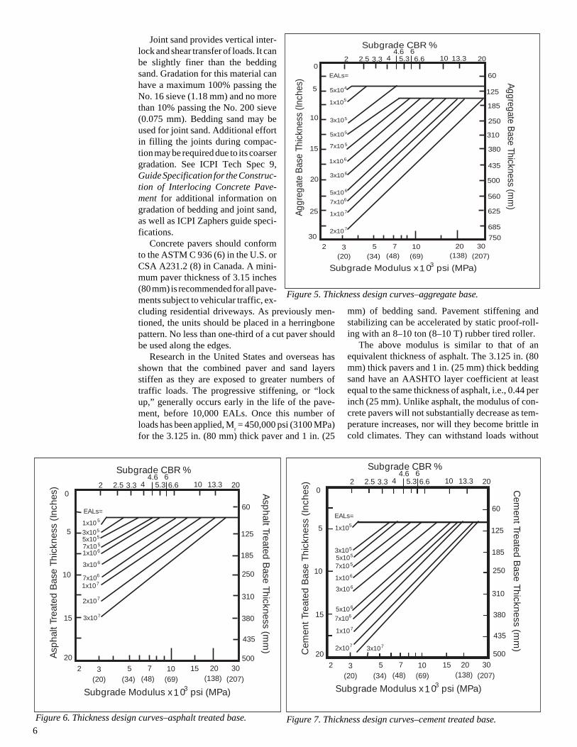
Figure 6. Thickness design curves–asphalt treated base.
Joint sand provides vertical inter-lock and shear transfer of loads. It canbe slightly finer than the beddingsand. Gradation for this material canhave a maximum 100% passing theNo. 16 sieve (1.18 mm) and no morethan 10% passing the No. 200 sieve(0.075 mm). Bedding sand may beused for joint sand. Additional effortin filling the joints during compac-tion may be required due to its coarsergradation. See ICPI Tech Spec 9,Guide Specification for the Construc-tion of Interlocing Concrete Pave-ment for additional information ongradation of bedding and joint sand,as well as ICPI Zaphers guide speci-fications.
Concrete pavers should conformto the ASTM C 936 (6) in the U.S. orCSA A231.2 (8) in Canada. A mini-mum paver thickness of 3.15 inches(80 mm) is recommended for all pave-ments subject to vehicular traffic, ex-cluding residential driveways. As previously men-tioned, the units should be placed in a herringbonepattern. No less than one-third of a cut paver shouldbe used along the edges.
Research in the United States and overseas hasshown that the combined paver and sand layersstiffen as they are exposed to greater numbers oftraffic loads. The progressive stiffening, or “lockup,” generally occurs early in the life of the pave-ment, before 10,000 EALs. Once this number ofloads has been applied, M
r = 450,000 psi (3100 MPa)
for the 3.125 in. (80 mm) thick paver and 1 in. (25
2 2.5 3.3 44.6
5.366.6 10 13.3 20
60
125
185
250
310
380
435
500
0
5
10
20
15 7x10 5
5x10⁵
3x10⁵
1x10⁶
3x10⁶
2x10⁷
7x10⁶
1x10⁷
Subgrade CBR %
Aggr
egat
e B
ase
Thic
knes
s (In
ches
) Aggregate Base Thickness (m
m)
2 3 5 7 10 20 30
(20) (34) (48) (69) (138) (207)
Subgrade Modulus x10 psi (MPa)3
EALs=
5x10⁶
5x10⁴
1x10⁵
25
30
560
625
685
750
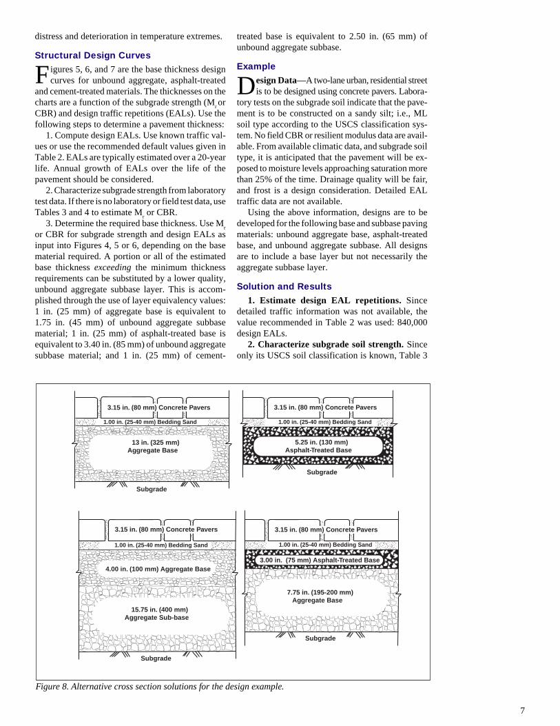
Figure 5. Thickness design curves–aggregate base.
2 2.5 3.3 44.6
5.366.6 10 13.3 20
60
125
185
250
310
380
435
500
0
5
10
20
15
7x10 55x1053x105
1x10⁶
3x10⁶
2x10⁷ 3x10⁷
7x10⁶
1x10⁷
Subgrade CBR %
Cem
ent T
reat
ed B
ase
Thic
knes
s (I
nche
s) Cem
ent Treated B
ase Thickness (mm
)
2 3 5 7 10 20 30
(20) (34) (48) (69) (138) (207)
Subgrade Modulus x10 psi (MPa)3
EALs=
5x10⁶
1x10⁵
15
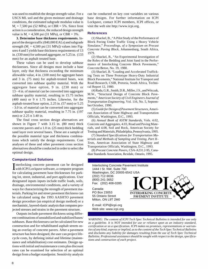
Figure 7. Thickness design curves–cement treated base.
7
distress and deterioration in temperature extremes.
Structural Design Curves
Figures 5, 6, and 7 are the base thickness designcurves for unbound aggregate, asphalt-treated
and cement-treated materials. The thicknesses on thecharts are a function of the subgrade strength (M
r or
CBR) and design traffic repetitions (EALs). Use thefollowing steps to determine a pavement thickness:
1. Compute design EALs. Use known traffic val-ues or use the recommended default values given inTable 2. EALs are typically estimated over a 20-yearlife. Annual growth of EALs over the life of thepavement should be considered.
2. Characterize subgrade strength from laboratorytest data. If there is no laboratory or field test data, useTables 3 and 4 to estimate M
r or CBR.
3. Determine the required base thickness. Use Mr
or CBR for subgrade strength and design EALs asinput into Figures 4, 5 or 6, depending on the basematerial required. A portion or all of the estimatedbase thickness exceeding the minimum thicknessrequirements can be substituted by a lower quality,unbound aggregate subbase layer. This is accom-plished through the use of layer equivalency values:1 in. (25 mm) of aggregate base is equivalent to1.75 in. (45 mm) of unbound aggregate subbasematerial; 1 in. (25 mm) of asphalt-treated base isequivalent to 3.40 in. (85 mm) of unbound aggregatesubbase material; and 1 in. (25 mm) of cement-
treated base is equivalent to 2.50 in. (65 mm) ofunbound aggregate subbase.
Example
Design Data—A two-lane urban, residential streetis to be designed using concrete pavers. Labora-
tory tests on the subgrade soil indicate that the pave-ment is to be constructed on a sandy silt; i.e., MLsoil type according to the USCS classification sys-tem. No field CBR or resilient modulus data are avail-able. From available climatic data, and subgrade soiltype, it is anticipated that the pavement will be ex-posed to moisture levels approaching saturation morethan 25% of the time. Drainage quality will be fair,and frost is a design consideration. Detailed EALtraffic data are not available.
Using the above information, designs are to bedeveloped for the following base and subbase pavingmaterials: unbound aggregate base, asphalt-treatedbase, and unbound aggregate subbase. All designsare to include a base layer but not necessarily theaggregate subbase layer.
Solution and Results
1. Estimate design EAL repetitions. Sincedetailed traffic information was not available, thevalue recommended in Table 2 was used: 840,000design EALs.
2. Characterize subgrade soil strength. Sinceonly its USCS soil classification is known, Table 3
Figure 8. Alternative cross section solutions for the design example.
3.15 in. (80 mm) Concrete Pavers
1.00 in. (25-40 mm) Bedding Sand
15.75 in. (400 mm)Aggregate Sub-base
Subgrade
4.00 in. (100 mm) Aggregate Base
3.15 in. (80 mm) Concrete Pavers
1.00 in. (25-40 mm) Bedding Sand
13 in. (325 mm)Aggregate Base
Subgrade
3.15 in. (80 mm) Concrete Pavers
1.00 in. (25-40 mm) Bedding Sand
5.25 in. (130 mm)Asphalt-Treated Base
Subgrade
3.15 in. (80 mm) Concrete Pavers
1.00 in. (25-40 mm) Bedding Sand
3.00 in. (75 mm) Asphalt-Treated Base
7.75 in. (195-200 mm)Aggregate Base
Subgrade
8
was used to establish the design strength value. For aUSCS ML soil and the given moisture and drainageconditions, the estimated subgrade modulus value isM
r = 7,500 psi (52 MPa), or CBR = 5%. Since frost
action is a consideration, the reduced design strengthvalue is M
r = 4,500 psi (31 MPa), or CBR = 3%.
3. Determine base thickness requirements. In-put of the design traffic (840,000 EALs) and subgradestrength (M
r = 4,500 psi [31 MPa]) values into Fig-
ures 4 and 5 yields base thickness requirements of 13in. (330 mm) for unbound aggregate, or 5.25 in. (133mm) for an asphalt treated base.
These values can be used to develop subbasethicknesses. Since all designs must include a baselayer, only that thickness exceeding the minimumallowable value, 4 in. (100 mm) for aggregate basesand 3 in. (75 mm) for asphalt-treated bases, wasconverted into subbase quality material. With theaggregate base option, 9 in. (230 mm) or13 - 4 in. of material can be converted into aggregatesubbase quality material, resulting in 15.75 inches(400 mm) or 9 x 1.75 inches. Likewise, for theasphalt-treated base option, 2.25 in. (57 mm) or 5.25- 3.0 in. of material can be converted into aggregatesubbase quality material, resulting in 7.75 in. (197mm) or 2.25 x 3.40 in.
The final cross section design alternatives areshown in Figure 7 with 3.15 in. (80 mm) thickconcrete pavers and a 1.0 in. (25 mm) thick beddingsand layer over several bases. These are a sample ofthe possible material type and thickness combina-tions which satisfy the design requirements. Costanalyses of these and other pavement cross sectionalternatives should be conducted in order to select theoptimal design.
Computerized Solutions
Interlocking concrete pavement can be designedwith ICPI Lockpave software, a computer program
for calculating pavement base thicknesses for park-ing lot, street, industrial, and port applications. Userdesignated inputs inputs include traffic loads, soils,drainage, environmental conditions, and a variety ofways for characterizing the strength of pavement ma-terials. Parking lot and street pavement thickness canbe calculated using the 1993 AASHTO pavementdesign procedure (an empirical design method) or amechanistic, layered elastic analysis that computes pro-jected stresses and strains in the pavement structure.
Outputs include pavement thickness using differ-ent combinations of unstabilized and stabilized bases/subbases. Base thicknesses can be calculated for newconstruction and for rehabilitated asphalt streets us-ing an overlay of concrete pavers. After a pavementstructure has been designed, the user can project life-cycle costs, by defining initial and lifetime (mainte-nance and rehabilitation) cost estimates. Design op-tions with initial and maintenance costs plus discountrates can be examined for selection of an optimaldesign from a budget standpoint. Sensitivity analysis
can be conducted on key cost variables on variousbase designs. For further information on ICPILockpave, contact ICPI members, ICPI offices, orvisit the web site http://www.icpi.org.
References(1) Shackel, B., “A Pilot Study of the Performance of
Block Paving Under Traffic Using a Heavy VehicleSimulator,” Proceedings, of a Symposium on PrecastConcrete Paving Block, Johannesburg, South Africa,1979.
(2) Shackel, B., “An Experimental Investigation ofthe Roles of the Bedding and Joint Sand in the Perfor-mance of Interlocking Concrete Block Pavements,”Concrete/Beton, No. 19, 1980.
(3) Shackel, B. “Loading and Accelerated Traffick-ing Tests on Three Prototype Heavy-Duty IndustrialBlock Pavements,” National Institute for Transport andRoad Research, CSIR, Pretoria, South Africa, Techni-cal Report 12, 1980.
(4) Rada, G.R., Smith, D.R., Miller, J.S., and Witczak,M.W., “Structural Design of Concrete Block Pave-ments,” American Society of Civil Engineers Journal ofTransportation Engineering, Vol. 116, No. 5, Septem-ber/October, 1990.
(5) Guide for Design of Pavement Structures, Ameri-can Association of State Highway and TransportationOfficials, Washington, D.C., 1993.
(6) Annual Book of ASTM Standards, Vols. 4.02,Concrete and Aggregates, 4.03, Road and Paving Mate-rials, and 4.08, Soil and Rock, American Society forTesting and Materials, Philadelphia, Pennsylvania, 1995.
(7) Standard Specifications for Transportation Ma-terials and Methods of Sampling and Testing, Part II–Tests, American Association of State Highway andTransportation Officials, Washington, D.C., 1993.
(8) Precast Concrete Pavers, CSA-A231.2-95, Cana-dian Standards Association, Rexdale, Ontario, 1995.
WARNING: The content of ICPI Tech Spec Technical Bulletins is intended for use onlyas a guideline. It is NOT intended for use or reliance upon as an industry standard,certification or as a specification. ICPI makes no promises, representations or warran-ties of any kind, express or implied, as to the content of the Tech Spec Technical Bulletinsand disclaims any liability for damages resulting from the use of Tech Spec TechnicalBulletins. Professional assistance should be sought with respect to the design, specifica-tions and construction of each project.
Interlocking Concrete Pavement Institute1444 I St. NW, Suite 700Washington, DC 20005-6542 USA(202) 712-9036(800) 241-3652Fax: (202) 408-0285
Canada:PO Box 2305355 Ontario StreetMilton, ON L9T 2M0
E-mail: [email protected] site: www.icpi.org