Subgrade Design Inputs - docs.lib.purdue.edu
62
Subgrade Design Inputs Kumar Dave, P.E. Manager, Pavement Engineering, INDOT 2015 Purdue Road School March 2015
Transcript of Subgrade Design Inputs - docs.lib.purdue.edu

Subgrade Design Inputs
Kumar Dave, P.E.Manager, Pavement Engineering, INDOT
2015 Purdue Road SchoolMarch 2015

JPCP cross section
9” – 13” JPCP
3” Open graded stone
6” Dense graded stone
Subgrade treatment
Soil Subgrade/natural

HMA pavement cross section
1.5” Surface
3”+ Dense graded base
3” Dense graded base
Subgrade treatment
Soil subgrade/natural
2.5” Intermediate
3” Open graded base

AASHTO 1993 Guide
Pavement Design Considerations:
Pavement performance
Traffic
Roadbed soil
Material for construction
Environment
Drainage
Reliability
Life Cycle cost
Shoulder design

Subgrade Design Inputs(1993)
Mr=Resilient Modulus(Psi) used for flexible pavement
Elastic property of soil(non linear)
Represents compacted layer of subgrade
K value=Modulus of subgrade reaction used for Rigid pavement
Mr=1500 X CBR
Mr from FWD used for Rehab

MEPDG(2009)
Mechanisti Empirical Pavement Design Guide
State-of-art tool for design and analysis of new and rehabilitated pavement structure
Based on M-E principles
Calculates pavement responses(stresses, strains & deflection)
Uses responses to calculate damage over time
MEPDG predicts multiple performance indicators
MEPDG(2009)
MEPDG is a iterative process
Outputs are pavement distresses and not tk
Trial design based on performance criteria
Level 1, 2, 3
Performance criteria for flexible pavement
Roughness(IRI)
Rutting
Transverse cracking
Fatigue cracking

MEPDG(2009)
Performance criteria for Rigid Pavement
Roughness(IRI)
Faulting
Cracking
Ref: Chapter 304 IDM

MEPDG(2009)
MEPDG design Considerations
Foundation/Subgarde
Existing pavement condition
Paving material
Construction factors
Environmental factors
Traffic loading
Subdarinage
Shoulder design
Rehabilitation treatment & strategies

Cont.
New pavement & rehab options
Pavement performance
Design relaibility
LCC
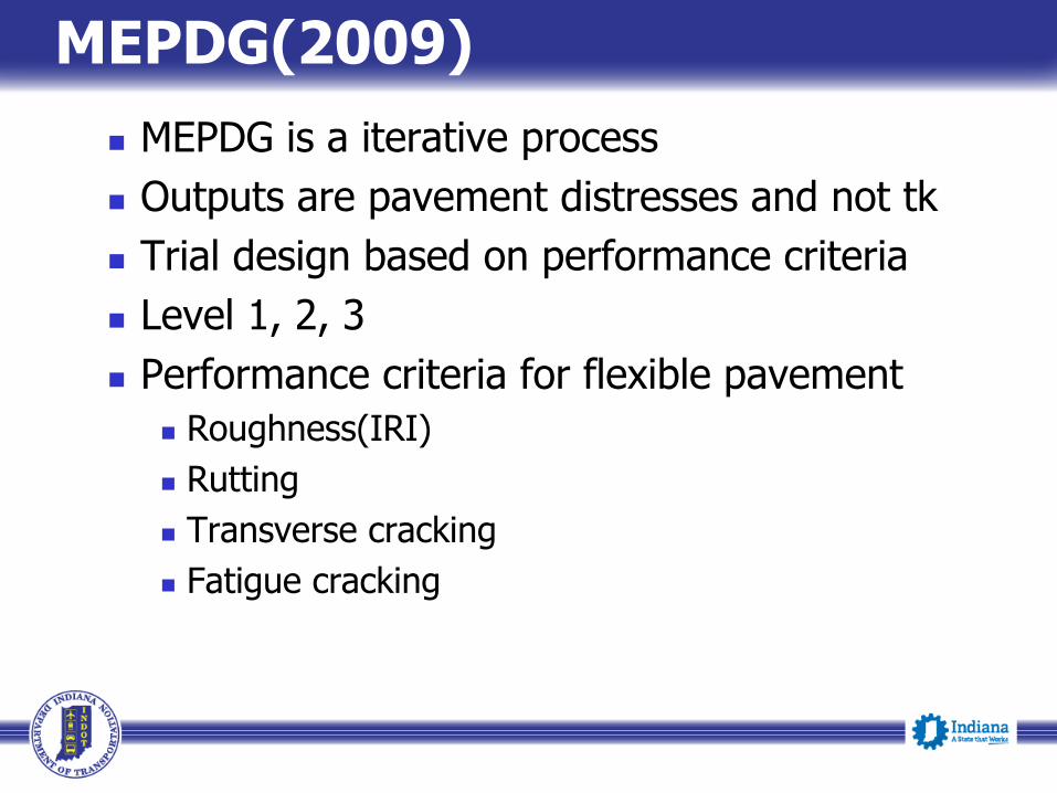
Subgrade/Foundation Inputs
Characterization of the pavement foundation
Subsurface characterization
Laboratory testing of subgrade soils
Condition of Mr lab test specimens
Identification and treatment of special subsurface condition
Foundation improvement & strengthening
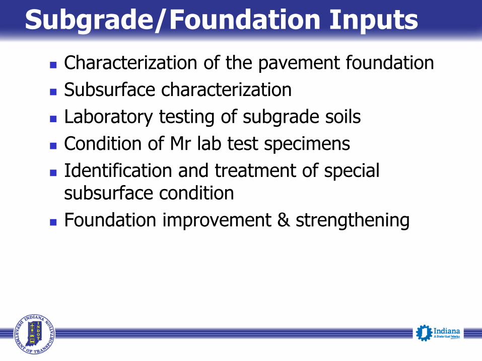
AASHTOWare Pavement ME….
Subgrade
General
Layer thickness (in): The thickness of the selected layer
Poisson's ratio: ME Design provides a default value of 0.35.
Coefficient of lateral earth pressure (k0): ME Design provides a default value of 0.5.

Modulus• Resilient Modulus (psi): This control allows you to define the level of inputs for resilient modulus of the subgrade material. This control also allows you to define the resilient modulus or the other material properties that correlate with the resilient
Resilient Modulus (psi): ME Design displays the default value (Level 3) for the selected material class
Input Level: 2 & 3
Level 2: directly or using its correlations with soil index and strength properties.
Level 3: override the default resilient modulus value (Level 3) of the subgrade material.
ME Design does not provide Level 1 input option for resilient modulus of subgrade materials.
Analysis Types
Seasonal variations (freezing, thawing and moisture)
Values by temperature/moisture:.
Monthly representative values:
Annual representative values:

Method
Resilient modulus (psi)
California Bearing Ratio (CBR) (percent)
R-value
Layer Coefficient-ai
Dynamic Cone Penetrometer (DCP) Penetration (in./blow)
Plasticity Index (PI) and Gradation (i.e., Percent Passing No. 200 sieve)
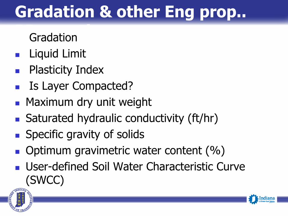
Gradation & other Eng prop.. PPropertiesGradation
Liquid Limit
Plasticity Index
Is Layer Compacted?
Maximum dry unit weight
Saturated hydraulic conductivity (ft/hr)
Specific gravity of solids
Optimum gravimetric water content (%)
User-defined Soil Water Characteristic Curve (SWCC)

Resilient Modulus
Nayyar Siddiki, P.E.Geotech Construction & Tech Support Engineer, INDOT
2015 Purdue Road SchoolMarch 2015

MR Research Under JTRP
FHWA/IN/JHRP 92-23, SPR-2032, Development Subgrade Resilient Modulus for Pavement Design and Evaluation, Woojin Lee, A.G. Altshaeffl
FHWA/JTRP 98-SPR-2134, Implementation of Subgrade Resilient Modulus for Pavement.
FHWA/JTRP 2010 SPR-3008, Evaluation of In-situ Stiffness of Subgrade by Resilient Modulus and FWD.

Base Stresses
σ v Vertical Stress
σ h Horizontal Stress

Major and Minor Principle Stresses

Deformation Under Load
Deformation
New Old

Deformation
Total Deformation consists of
Two Components:
Elastic Recoverable
Plastic Permanent

Resilient Modulus:Dynamic Deviator Stress/Resilient Strain
Str
ess
Strain

As the confining stress on the base material increases the stiffness on the Mr increases.
Mr
Stress

Resilient Modulus, MR
Units of Stress – psi, ksi, kPa, etc.
Strain eRecoverablStress
RM

AASHTO Classifications
General Class.Granular Materials
(35% Or Less Passing No. 200)
Silt-Clay Materials
(More than 35% Passing No. 200)
Group/
Classifications
A-1
A-3
A-2
A-4 A-5 A-6
A-7
A-1-a A-1-b A-2-4 A-2-5 A-2-6 A-2-7A-7-5
A-7-6
Sieve
Analysis, %
Passing
No. 10
No. 40
No. 200
50 max.
30 max.
15 max.
_____
50 max.
25 max.
______
51 min.
10 max.
______
______
35 max.
_____
_____
35 max.
______
______
35 max.
______
______
35 max.
______
______
36 min.
______
______
36 min.
______
______
36 min.
______
______
36 min.
Charac.'s of
Fraction
passing No. 40
Liquid Limit
Plasticity
Index______
6 max.
______
N.P.
40 max.
10 max.
41 min.
10 max.
40 max.
11 min.
41 min.
11 min.
40 max.
10 max.
41 min.
10 max.
40 max.
11 min.
41 min.
11 min.
Usual types of
Significant
Constituent
Materials
Stone Fragments,
Gravel and SandFine Sand Silty or Clayey Gravel and Sand Silty Soils Clayey Soils
General Rating
as SubgradeExcellent to Good Fair to Poor
Classification of Soil and Soil-Aggregate Mixtures from AASHTO M-145

How is the Resilient Modulus performed?

The Laboratory Model
The pavement stresses are modelled in the laboratory in a triaxial cell.
Cylindrical soil specimen separated from cell pressure by rubber membrane.
Cell is pressurized to provide confining stress (normal stress).
Hydraulic actuator ram provides cyclic shear and normal stresses.
Digitally controlled.
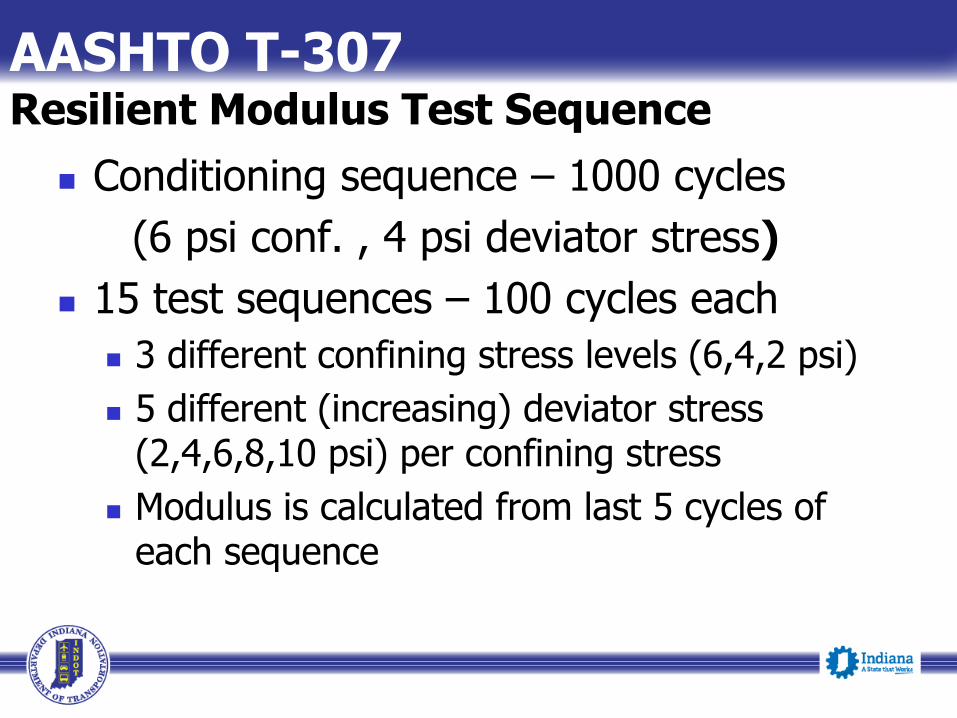
Conditioning sequence – 1000 cycles
(6 psi conf. , 4 psi deviator stress)
15 test sequences – 100 cycles each
3 different confining stress levels (6,4,2 psi)
5 different (increasing) deviator stress (2,4,6,8,10 psi) per confining stress
Modulus is calculated from last 5 cycles of each sequence
AASHTO T-307Resilient Modulus Test Sequence

Resilient Modulus Machine

Resilient Modulus Machine

Resilient Modulus Machine

A specimen shall be molded at 95% compaction at OMC.
A Shelby sample for MR
Data sheet of a resilient modulus test showing the stress sequence shall be provided.
Data sheet shall include: confining stress, deviator stress, resilient strain, permanent strain, resilient modulus etc.
Preparing the Sample

Typical Confining and Deviatoric Stress Values
Confining Stress (psi)
(δc or δ3)
Deviatoric Stress (psi)
(δd or δcyclic)
References
2 5.4 Rahim (2005)
2 7.5 George (2004)
2 5 Ping et al. (2001)
2 6 Asphalt Institute (as cited by Ping et al. 2001)
2 2 Daleiden et al. (as cited by Ping et al. 2001)
2 6 Lee et al. (1997)
2 6 Jones and Witczak (1977)

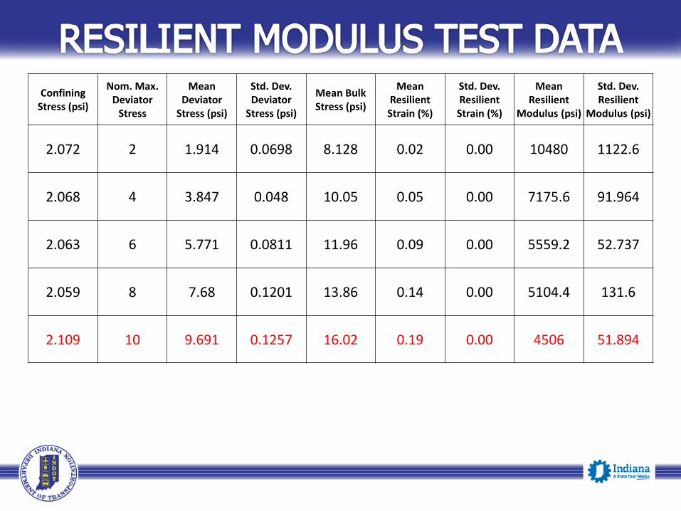
Confining Stress (psi)
Nom. Max. Deviator
Stress
Mean Deviator
Stress (psi)
Std. Dev. Deviator
Stress (psi)
Mean Bulk Stress (psi)
Mean Resilient Strain (%)
Std. Dev. Resilient Strain (%)
Mean Resilient
Modulus (psi)
Std. Dev. Resilient
Modulus (psi)
2.072 2 1.914 0.0698 8.128 0.02 0.00 10480 1122.6
2.068 4 3.847 0.048 10.05 0.05 0.00 7175.6 91.964
Confining Stress (psi)
Nom. Max. Deviator
Stress
Mean Deviator
Stress (psi)
Std. Dev. Deviator
Stress (psi)
Mean Bulk Stress (psi)
Mean Resilient Strain (%)
Std. Dev. Resilient Strain (%)
Mean Resilient
Modulus (psi)
Std. Dev. Resilient
Modulus (psi)
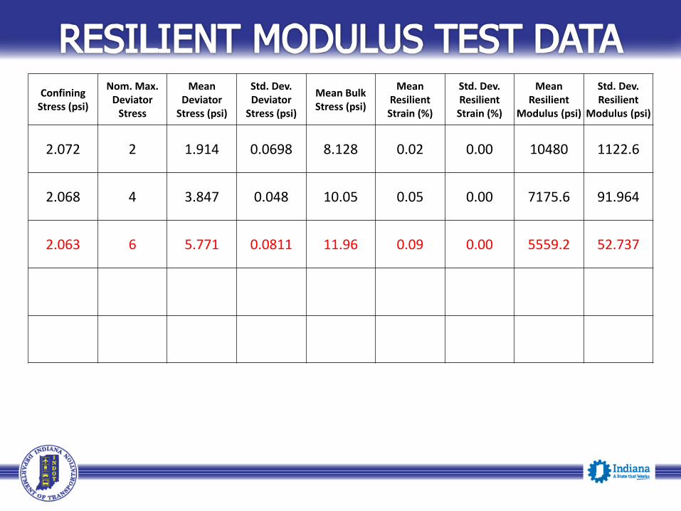
2.072 2 1.914 0.0698 8.128 0.02 0.00 10480 1122.6
2.068 4 3.847 0.048 10.05 0.05 0.00 7175.6 91.964
2.063 6 5.771 0.0811 11.96 0.09 0.00 5559.2 52.737

Confining Stress (psi)
Nom. Max. Deviator
Stress
Mean Deviator
Stress (psi)
Std. Dev. Deviator
Stress (psi)
Mean Bulk Stress (psi)
Mean Resilient Strain (%)
Std. Dev. Resilient Strain (%)
Mean Resilient
Modulus (psi)
Std. Dev. Resilient
Modulus (psi)
2.072 2 1.914 0.0698 8.128 0.02 0.00 10480 1122.6
2.068 4 3.847 0.048 10.05 0.05 0.00 7175.6 91.964
2.063 6 5.771 0.0811 11.96 0.09 0.00 5559.2 52.737
2.059 8 7.68 0.1201 13.86 0.14 0.00 5104.4 131.6
2.109 10 9.691 0.1257 16.02 0.19 0.00 4506 51.894

JTRP MR Report Conclusion
Deviator Stress = 6 psi
Confining Stress = 2 psi
Based on limited Testing for A-6, A-7, A-4 (Indiana Soils)
MR = 695.4 (Su 1%) – 5.93 (Su 1%)2
Su at 1% Strain rate
R2 = .97

MR and CBR Relations
Mr (ksi) = 1.42 x CBR (Heukelom and Klomp)
Mr (ksi) = 5.409 x CBR0.711 (Green and Hall)
Mr (ksi) = 2.554 x CBR0.64 (Powell et. al.)
Mr (ksi) = 1.2 x CBR (Ohio DOT)
Mr (psi) = 1500 x CBR (INDOT)

Mr Test for FDR Samples
Sample No. Sample Description
Compaction AASHTO
T-99 (Method A)
Dry Density & Moisture Content
(Before & After Test)
Max. Dry
Density
( pcf)
OMC %%
Compaction
Molded Dry
Density (pcf)MC %
1Sample passing (# 4 Sieve)
and mix with (5 % Cement)125.5 6 93 116.5 6.4
3Sample passing (# 4 Sieve)
and mix with (5 % Cement)125.5 6 93 116.6 7
4Sample passing (# 4 Sieve)
and mix with (5 % Cement)125.5 6 92 116.1 6.8
5Sample passing (# 4 Sieve)
and mix with (5 % Cement)124.5 6.4 95 117.8 8
6Sample passing (# 4 Sieve)
and mix with (5 % Cement)124.5 6.4 95 118.7 8
Note: Sample 2 was crumbled during the test.

Resilient Modulus (MR) of FDR Samples
Sample
No.Confining
Stress (psi)
Deviator
Stress (psi)Avg. MR (psi) R2
1
6 *2 thru 10 15660
0.86284 2 thru 10 16246
2 2 thru 10 13086
Passing No. 4 sieve material
3
6 2 thru 10 18613
0.81474 2 thru 10 14085
2 2 thru 10 9864
4
6 2 thru 10 15262
0.89594 2 thru 10 12962
2 2 thru 10 9390
5
6 2 thru 10 33491
0.88524 2 thru 10 27954
Note: 59 % Material passing # 4 sieve. 2 2 thru 10 26301
* Deviator Stress: 2,4,6,8,10
6
6 2 thru 10 20626
0.8131Sample No. 5 tested 3% above the OMC 4 2 thru 10 17618
Sample # 2 was crumbled during test.2 2 thru 10 13909

Typical Pavement Subgrade Recommendations
Subgrade Type in accordance with 207.04
Resilient Modulus of prepared subgrade xxxx psi
Resilient Modulus of undisturbed subgrade xxxxpsi
Predominant Soil encountered in Subgrade INDOT Textural Classification AASHTO
Presence of Groundwater Table…(based on boring information)
Subsurface drains if Geotechnical problems exist
Filter fabric if soils are silty (> 50% or soils are erodible)

INDOT Policy For MR test
INDOT has been performing the MR test for Geotechnical consultants on state projects.
On Local agency projects the Mr test is required to go to an Approved Geotechnical Laboratory.

Geotechnical consultants will provide the following:
Shelby Tube Sample (≥ 50 % recovery)
A 10 lb. sample bag (Passing #4 sieve)
Specific Gravity test
Atterberg Limits Testing
Moisture Density Curve (Standard Proctor)

Optimum Moisture, Maximum Wet & Dry Densities
Natural Moisture Test (as received)
Sample bag must contain following information: Date, Geotechnical Consultant, Des # and/or
Contract #, Road, County, Boring #, Sample Depth, Station, and Location.

Resilient Modulus Sample Info
Sample ID
Soils Classification
AASHTO Class. & Group Index
Passing #10
Passing #40
Passing #200
% Gravel
% Sand
% Silt
% Clay
LL
PL
PI
Sulfate Content ppm
Specific Gravity
LOI
Ca/mg
Max Wet Density
Max Dry Density
Optimum Moisture

Pavement, Subgrade & It’s Foundation Section
Aggregate No. 53
Drainage Layer &Separation Layer
PCCP
Subgrade Foundation
Subgrade varies 6 to 24 inches

Type I24 in. of soil compacted to density and moisture requirements.
24 in. SoilCompactedto Density andMoistureRequirements
Subgrade Types
Road Description Type of Work Subgrade Length Maximum Design MR
CR/SRNew Road, Road
Reconstruction and > 6 feet Widening
> 800 feet MR = 6,000 psi
CR-County Road US-US Route LS-Local Street I-InterstateSR-State Road

14 in. chemical soil modification 14 in. Chemical Soil
Modification
Type 1B
Road Description Type of Work Subgrade Length Maximum Design MR
CR/SR/US/INew Road, Road
Reconstruction and > 6 feet Widening
> 800 feet MR = 9,500 psi

12 in. of the subgrade excavated and replaced with coarse aggregate No. 53
12 in. in. Coarse Aggregate No. 53
Type 1C
Road Description Type of Work Subgrade Length Maximum Design MR
CR/SR/US/I
New Road, Road Reconstruction and
> 6 feet Widening ORReconstruction or Widening < 6 feet
< OR > 800 feet MR = 9,500 psi

6 in. of the subgrade excavated and replaced with coarse aggregate No. 53.
6 in. Coarse Aggregate No. 53
Type II
Road Description Type of Work Subgrade Length Maximum Design MR
SR/USRoad Reconstruction or
< 6 feet Widening> Or < 800 feet MR = 6,000 psi
8 in. chemical soil modification
8 in. Chemical SoilModification
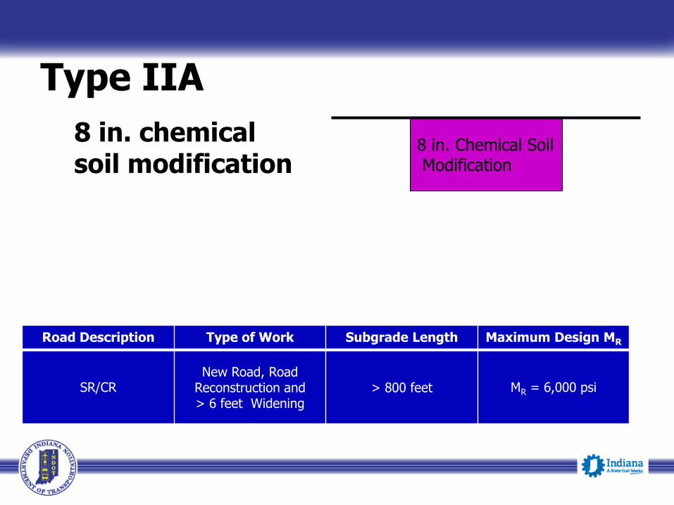
Type IIA
Road Description Type of Work Subgrade Length Maximum Design MR
SR/CRNew Road, Road
Reconstruction and > 6 feet Widening
> 800 feet MR = 6,000 psi

6 in. of soil compacted to the density and moisture requirements
6 in. Soil Compacted to Moisture Density Requirements
Type III
Road Description Type of Work Subgrade Length Maximum Design MR
CR/or other local roadsRoad Reconstruction or
Widening< 800 feet MR = 4,500 psi

12 in. of the subgrade excavated and replaced with Coarse Aggregate No. 53 on geogrid Type IB.
12 in. Coarse Aggregate No. 53
Type IV
Geogrid Type IB
Road Description Type of Work Subgrade Length Maximum Design MR
CR/US/SR/LS/IReconstruction and < 6 feet Widening
> 800 feet MR = 9,500 psi

3 in. of the subgrade excavated and replaced with 3 in. coarse aggregate No. 53.
3 in. Coarse Aggregate No. 53
Type V
Subgrade Treatment for Trails on Abandoned-Railroad Corridor
Road Description Type of Work Subgrade Length Maximum Design MR
Bike Paths/TrailsReconstruction or
Widening--------------- MR = 4,500 psi

Following procedure should be used for Resilient Modulus sampling for cohesive soils:
Re-Construction/ New Construction
A continuous flight auger shall be used to penetrate the existing pavement and pavement sub-base material to a depth approximately 4-6 inches blow the top of the subgrade.
A 24 inch long and 3 inches in diameter Shelby Tube sample shall be collected from the borehole. The sample shall have minimum of 50% recovery.

Upon completion of the Shelby tube sampling the flight auger shall be reintroduced to the borehole and advanced to a depth of approximately 4-5 feet.
Approximately 25 lbs. of auger cuttings shall be collected for the bag sample.
Soils from bag sample and Shelby Tube sample should be the same.
Rubblization / Full depths Reclamation etc.
Shelby Tube Sample / Soil samples to be remolded for MR.
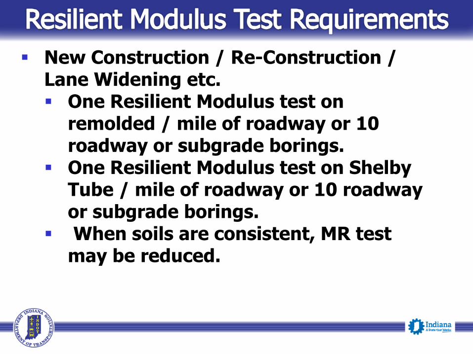
New Construction / Re-Construction / Lane Widening etc. One Resilient Modulus test on
remolded / mile of roadway or 10 roadway or subgrade borings.
One Resilient Modulus test on Shelby Tube / mile of roadway or 10 roadway or subgrade borings.
When soils are consistent, MR test may be reduced.

For FDR projects :A resilient modulus on Shelby Tube or remolded to natural density / mile of roadway or 10 roadway borings.
Roadway <800 Lft. MR can be estimated from unconfined test of 1% strain rate. (Woojin & Lee eq.)

Questions?