Tech Op FR.28/9/01 - ShoulderDoc by Prof. Lennard Funk ... · summary displaced 4-part fracture of...
32
Aequalis-Fracture Shoulder Prosthesis Surgical Technique
Transcript of Tech Op FR.28/9/01 - ShoulderDoc by Prof. Lennard Funk ... · summary displaced 4-part fracture of...
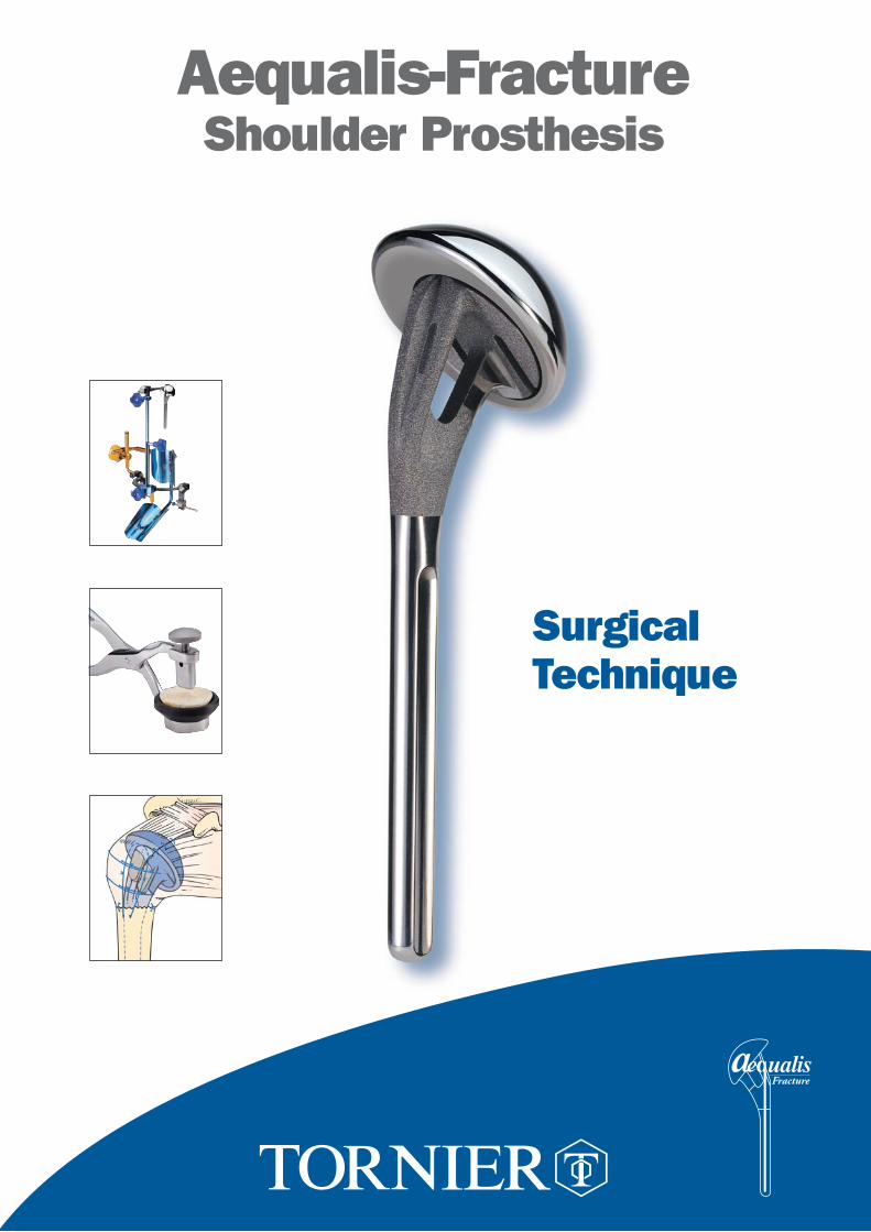
Aequalis-FractureShoulder Prosthesis
SurgicalTechnique

SUMMARY
DISPLACED 4-PART FRACTURE OF THE PROXIMAL HUMERUS p. 1
RATIONALE FOR A SHOULDER SOLUTION IN THE CASE p. 1 - 5OF FOUR PART FRACTURE
SURGICAL TECHNIQUE p. 6 - 241. Pre-operative planning
2. Patient positioning
3. Deltopectoral approach and exposure
4. Identification of the lesser and greater tuberosities and anterosuperior arthrotomy
5. Tenotomy and excision of the long head of the biceps
6. Extraction of humeral head fragment and choice of prosthetic head
7. Placing of four horizontal stay sutures in the rotator cuff
8. Humeral reaming
9. Choice of the trial prosthesis and attachment to the fracture jig
10. Pre-fixing of height and retroversion
11. Implantation and reduction of the trial prosthesis
12. Identification of the epicondyles and stabilization of the trial prosthesis
13. Reduction of the greater tuberosity around the trial prosthesis and testing of the heigh
14. Removal of the trial prosthesis
15. Drilling the diaphysis and placement, of the two vertical sutures
16. Assembling the implant
17. Cementing the implant
18. Removal of excess cement and placing of the cancellous bone graft
19. Removal of two cancellous bone grafts with the bone graft cutter
20. Positioning the bone graft into the fenestration of the prosthesis
21. Placement of four horizontal sutures around the prosthetic neck
22. Positioning of the bone graft on the flat lateral base of the neck
23. Two horizontal cerclage sutures around the greater tuberosity
24. Two horizontal cerclage sutures around both tuberosities
25. Vertical tension band sutures on both tuberosities
26. Closing and tenodesis of the long biceps
27. Evaluation of the prosthetic stability and mobility
28. Final closing and immobilization of the arm in abduction and neutral rotation
POST OPERATIVE REHABILITATION p. 25
ASSEMBLY INSTRUCTIONS LEFT ARM p. 26
ASSEMBLY INSTRUCTIONS RIGHT ARM p. 27
INSTRUMENTATION (Common instruments utilized in case of fracture) p. 28
INSTRUMENTATION (Common instruments not utilized in case of fracture) p. 29
IMPLANTS p. 30

1
DISPLACED 4-PART FRACTURE OF THE PROXIMAL HUMERUS
Pathophysiology of displaced 4-part fractures involveseach muscle or muscle group pulling the fragments in various directions.
The diaphysis (1) is drawn medially by the pectoralismajor and latissimus dorsi muscles and is separatedfrom the epiphysis at the surgical neck.
The lesser tuberosity (2) is retracted anteromedially by subscapularis.
The greater tuberosity (3) is retracted medially, superiorly and posteriorly by the supraspinatus,infraspiratus and teres minor. The tuberosities may remain intact or be fragmented,and may be separated or remain in continuity with oneanother (impacted type).
The humeral articular surface (4) is no longer in contact with the glenoid: it is separated from thetwo tuberosities and may undergo varus or valgus displacement, displaced anteriorly or posteriorly, or displaced laterally or inferiorly usually resulting in devascularization. It may present an impactedfracture or a displaced fracture.
RATIONALE FOR A SHOULDER SOLUTION IN THE CASEOF FOUR PART FRACTURE
MAJOR PROBLEM for a fracture prosthesis procedure:Nonunion and migration of the tuberosities

2
1. Rationale for a fracture stem
• The metal volume of the prosthetic neck of standard prosthesis is an obstacle to tuberosity fixation and healing.
• Bone grafting is mandatory if tuberosity healing is to be obtained.
• A prosthetic fin is useless and can be detrimental: positioning the greater tuberosity too posteriorly, and the lesser tuberosity too laterally.
• The surface aspect of the prosthesis must not be too rough to avoid suture breakage.
2. Rationale for a Fracture Jig
• Intra operative instability of the humeral prosthesis make difficult accurate final positioning.

C D
B
• A prosthesis positioned too high is at the origin of a detachment and a migrationof the greater tuberosity.
• An excess of retroversion can produce as well a detachment and a migration of the greater tuberosity.
3. Rationale for a standardized tuberosity fixation
• With the classical technique (passing sutures through the prosthetic fin), the tuberosities cannot be adjusted and securely immobilized.
• Use of medial cerclage sutures is simple, reproducible and secure. Passing the sutures around the prosthetic neck is less aggressive for the tuberosities.
3

4
THE AEQUALIS-FRACTURE SOLUTION
Open neck for bone grafting
Low profile
Eccentric head(different sizes)
Rough surface for maximal boneadhesion
Polished medial neckto avoid abrasionsuture
TitaniumPolished stem for cementing130 mm length130° inclination6,5/9/12 mm diameter
1. The prosthesis

5
THE AEQUALIS-FRACTURE SOLUTION
The bone graft cutter
The bone graft cutter is designed to removecancellous bone from the humeral head for incorporation into the prosthetic metaphysis, improving the metaphyseal bone adhesion.
The standardized fixation technique with medial cerclage suture
Detachment and migration of the tuberosities are the most common complications after shoulder replacement for fractures. The quality of the suture wire and the technique for placing the tuberosities are critical.
The Aequalis-Fracture Jig
The Aequalis Fracture Jig is designed, to stabilize the prosthesis and, to assist the surgeon in more precisely positioning the humeral implant in both height and retroversion.

L' =
330
mm
I' =
105
mm
C
A
D
B
X
Y Y'
X'
6
SURGICAL TECHNIQUE
Example of calculation of humeral length taking into account the radiological magnification: the actual length between the two markers is 100 mm; the measured length between the two markers (A-B) is 105 mm; the measured length of the healthy humerus (C-D) is 330 mm.Therefore, using a rule of three:
105 100 mm330 L’
L = 330 x 100/105 ~ 314 mmThe actual length of the healthy humerus is therefore 314 mm, a measurement that should be entered on the fracture jig height ruler (see page 12).
1. Pre-operative planning:
• The stabilization of the prosthesis is automatically obtained whyle using the fracture jig.• The prosthetic retroversion is fixed at 20 degrees from the trans-epicondylare axis (average value).• The prosthetic height can be choosen:- per-operatively, using the bony aspect and the soft tissu without any pre-operative planning(approximate heigh).- pre-operatively, using a scaled x-ray of the healthy controlateral humerus (precise heigh).A ruler with two marker points as a distance of 100 mm will allow for radiographic magnificationscale determination.
Recommendation: place the ruler with the marker point and the arm parallel to the x-ray cassetteto minimize errors of measurement. A small cushion is placed under the elbow.
Ruler

7
2. Patient positioning:
General anesthesia, beach chair position, shoulder free of the table. The shoulder and entire upperextremity are prepared and draped. The arm support for the fracture jig is secured to the arm using a sterile elastic bandage. The elbow must be carefully positioned to fit correctly in the support.
The arm support is fixed, leaving the elbow uncovered at the level of the angle of the support. The entire shoulder must be free of the table to allow the jig to be correctly positioned.

8
3. Deltopectoral approach and exposure:
An incision is made from the tip of the coracoid process along the deltopectoral groove, slightly laterally to avoid post-operative scars in the axillary fold. The deltopectoral groove is opened to the insertion of the pectoralis major, and the deltoid and cephalic vein are retracted laterally.
The coracoid process is identified to allow the insertion of a Hohman retractor above it. The clavicular, acromial and humeral insertions of the deltoid are always preserved.The clavipectoral fascia is incised at the lateral border of the conjoined tendon of the coracobrachialisand the short head of the biceps. Usually the coracoacromial ligament is preserved.
4. Identification of the lesser and greater tuberosities and anterosuperior arthrotomy:
The glenohumeral joint is approached by extending the fracture line between the tuberosities, incising the rotator interval over the long head of the biceps tendon.
9
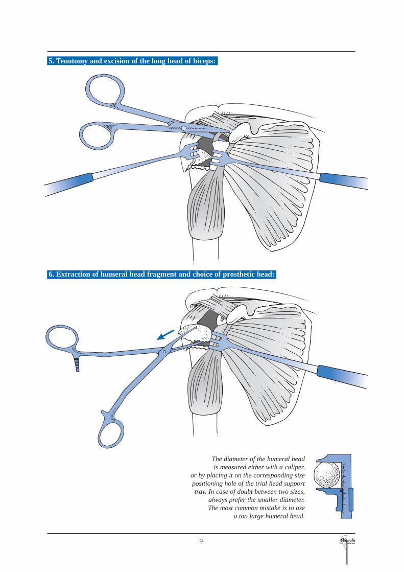
6. Extraction of humeral head fragment and choice of prosthetic head:
The diameter of the humeral head is measured either with a caliper,
or by placing it on the corresponding sizepositioning hole of the trial head supporttray. In case of doubt between two sizes,
always prefer the smaller diameter.The most common mistake is to use
a too large humeral head.
5. Tenotomy and excision of the long head of biceps:
10
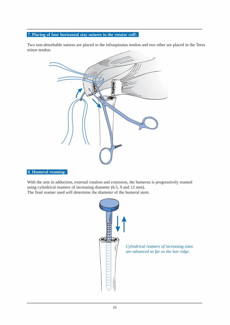
7. Placing of four horizontal stay sutures in the rotator cuff:
Two non-absorbable sutures are placed in the infraspinatus tendon and two other are placed in the Teresminor tendon.
8. Humeral reaming:
With the arm in adduction, external rotation and extension, the humerus is progressively reamedusing cylindrical reamers of increasing diameter (6.5, 9 and 12 mm). The final reamer used will determine the diameter of the humeral stem.
Cylindrical reamers of increasing sizesare advanced as far as the last ridge.

Illustra
11
9. Choice of trial prosthesis and attachment to the fracture jig:
To accurately reestablish humeral head width, we recommend the use of a prosthetic humeral head of the same size as the removed head. The humeral head should be positioned either on the 1 or 8 index (depending whether it is a right or left shoulder). This allows the highest lateral offset. Thereby the bone graft and the greater tuberosity are stabilized on the metaphyseal neck of the prosthesis.
The trial prosthesis is secured to the prosthesis holder using to the two holes placed on the low profile lateral part of the implant. The prosthesis holder is then fixed to the fracture jig.
Position 1 or 8

24
25
26
27
28
29
30
31
32
33
50
4 0 40
50
3 02 0 1 0 0
34
RE
TR
OT
OR
SIO
N
BR
AS
GA
UC
HE
RE
TR
OT
OR
SIO
NB
RA
SD
RO
IT
C
A
D
E
B
X
Y Y'
X'
12
10. Pre-fixing of height and retroversion:
• The height has been defined by the pre-operative planning.• The retroversion is set at 20° which is an average value based on anatomic studies from Gilles Walch and Pascal Boileau.
The Aequalis-fracture jig is composed of:• a ruler, to determine the humeral height• a protractor, to determine the humeral retroversion.The humeral height is determined in relationto the metaphyso-diaphyseal axis (A-B), the top of the greatertuberosity (C) and the medial epicondyle (D),while the humeral retrotorsion is determined in relation to the axis of the epicondyles (D-E).
N.B.: the proximal metaphyso-diaphyseal axis (A-B)represents the axis of the future prosthetic stem.It must not be confused with the diaphyseal axis, at the riskof causing a valgus position of the prosthesis and givinga false measurement of length.

13
11. Implantation and reduction of the trial prosthesis:
Positioning of the remaining components of the fracture jig assembly (protractor, ruler, prosthesis holder and trial prosthesis) must be done with the arm in extension.
Once the trial prosthesis has been inserted into the humerus, the arm is placed in flexionto reduce the glenohumeral joint.
Arm inextension.
Position of the arm.Trial prosthesis reduced.

14
12. Identification of the epicondyles and stabilization of the trial prosthesis:
The adjustment of height and retroversion begins by the placement of the epicondylar pads on the medial and lateral epicondyles.The surgeon positions each epicondylar pad on the prominences of the lateral and medial epicondyles. At the same time, the assistant connects the protractor to the arm support, securing the two angle joints by using knob n° 4.The fracture jig is then secured, allowing the selection of height and retroversion and a trial reduction.
Knob n° 4

15
13. Reduction of the greater tuberosity around the trial prosthesis and testing of the heigh:
The initial reduction of the prosthesis and the greater tuberosity enables both the height andthe retroversion to be tested. The greater tuberosity is placed on the diaphysis and the prosthesis, effectively testing the height of the prosthesis. There are three landmarks of interest:
The height of the acromiohumeral space, which is usually 10 mm.The top of the greater tuberosity, which should be located 5 mm below the upper limit of the prosthetic head.There must be no diastasis or overlap between the greater tuberosity and the humeral diaphysis. The lesser tuberosity is then reduced to verify the adjustement with the greater tuberosity and the diaphysis. Once the all adjustements performed, the trial prosthesis is withdrow.
14. Removal of the trial prosthesis:
The shoulder is placed in extension to dislocate the trial prosthesis. The prosthetic holder and the trial are prosthesis are removed, leaving the remaining of the fracturejig in place.
15. Drilling the diaphysis and placement, of the 2 vertical sutures:
Two holes are drilled on each side of the bicipital groove.Two non-absorbable sutures are passed through the holes.
1
2
3

16
16. Assembling the implant:
➔ Assembling
The assemby of the implant is done by impaction of the prosthetic head onto the stem.The assembly is secured by a morse taper system.
The prosthetic head is positioned on the stem, aligning the offset number (index 1 or 8) with superior aspectof the stem.
➔ Impaction
The prosthesis is positioned on the impaction support. The blocking screw of the impaction support is tightened with a 4.5 mm screwdriver to secure the prosthesis during impaction. A mallet is used to firmly engage the headon to the stem taper.
1
2

17
The implant is attached to the prosthesis holder in the same manneras the trial stem. The prosthesis is introduced into the medullary canal as the prosthesisholder is introduced into the ruler,then tightening knob n° 3.
3
17. Cementing the implant:
After placement of a cement restrictor, the canal is dried, and cement is injectedusing a large syringe.
18
Ciment
Bone graft
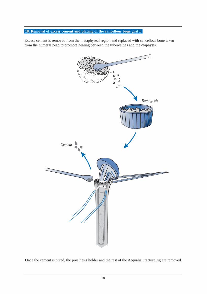
Once the cement is cured, the prosthesis holder and the rest of the Aequalis Fracture Jig are removed.
Cement
18. Removal of excess cement and placing of the cancellous bone graft:
Excess cement is removed from the metaphyseal region and replaced with cancellous bone takenfrom the humeral head to promote healing between the tuberosities and the diaphysis.

19
One graft is introduced into the fenestration of the prostheticneck.
19. Removal of two cancellous bone grafts with the bone graft cutter:
Bone grafting is highly recommended to improve tuberosity healing. Two bone grafts, are removed fromthe resected humeral head by using the bone graft cutter.The bone graft cutter allows to remove two bone grafts and to shape them according to the fenestration of the prosthesis, from the resected humeral head. The “bone graft extracting mechanism” (BGEM) is unscrewed and the humeral head is placed in the base of the bone graft cutter. The bone graft cutter handles are firmly tightened to cut the bone graft. In the case of exceptionallyhard bone, a mallet can be used to impact the clamp.The positioning of the two bone grafts is described in paragraph 20 and 22.
The BGEM is then screwed down to extract the resected bone graft.
One graft is positioned on the lateral prosthetic surface.

20. Positioning the bone graft into the fenestration of the prosthesis:
21. Placement of four horizontal sutures around the prosthetic neck:
Reconstruction begins with the greater tuberosity,and employs two of the four horizontal sutures placed earlier. Passing these sutures through the prosthetic fin does not provide enough stability to the fixation of the tuberosities. Therefore we recommend that they are passed around the prosthetic neck.
22. Positioning of the bone graft on the flat lateral base of the neck:
20

21
23. Two horizontal cerclage sutures around the greater tuberosity:
Fixation of the greater tuberosity begins with two horizontal cerclages to anatomically position the tuberosity. The arm is placed in neutral position. A clamp is used to pull the greater tuberosity anteriorly, reducing the greater tuberosity to the prosthesis. The two horizontal sutures (one superior, one inferior) are then tied to secure the greater tuberosity to the prosthesis.

22
24. Two horizontal cerclage sutures around both tuberosities:
The next step is the reconstruction of the lesser tuberosity, which also uses two of the four horizontalsutures. The two remaining horizontal sutures, which had initially been passed around the greatertuberosity, are then passed through the subscapularis tendon from inside to outside. This maneuver pulls the lesser tuberosity into position under the prosthetic head.

25. Vertical tension band sutures on both tuberosities:
The final tightening-up is performed in the vertical plane, using the two nonabsorbable sutures from the diaphysis in a tension-band technique. One suture is passed anteriorly through the subscapularisand the supraspinatus tendons, while the other suture is passed posteriorly through the infraspinatusand supraspinatus tendons. This provides the all-important fixation of the tuberosity fragments to the humeral shaft.
26. Closing and tenodesis of the long biceps:
Biceps TenodesisAfter resecting the intra-articular portion of the long head of biceps, a nonabsorbable suture is passed through its free end using a modified Kessler stitch.The tendon is relocated in the bicipital groove,with one end of the suture passed through the supraspinatus tendon. The suture is then tied.
23

27. Evaluation of the prosthetic stability and mobility:
With the arm in neutral position, it is recommended to have a posterior translation of approximately 25% to 50% with an automatic reduction.
A minimum external rotation of 40° is recommended.The greater tuberosity should not move as the arm is internally rotated.
28. Final closing and immobilization of the arm in abduction and neutral rotation.
24
40°

25
POST OPERATIVE REHABILITATION
The post operative Xrays shows a perfect anatomical reconstruction of the humerus thanks to the Aequalis-Fracture solution.
Postoperative rehabilitation is equally important after shoulder arthroplasty for a fracture case as it isfollowing shoulder arthroplasty for chronic etiologies, contributing at least 50% to the final outcome.Rehabilitation after prosthetic replacement of a 4 part proximal humerus fracture is perhaps the mostchallenging aspect of shoulder rehabilitation.In order to avoid complications such as hemarthrosis, hematoma, and prosthetic instability, it is recom-mended to delay the postoperative rehabilitation until the tuberosities have healed, 45 to 60 days pos-toperatively.
Because of frequent tuberosity fixation failure previously observed, the aggressiveness of postopera-tive rehabilitation has been reduced to avoid these potentially catastrophic complications. Early passivemotion is not recommended because it is easier to treat a stiff shoulder than a tuberosity migration ornonunion.
The patient’s arm is immobilized in 45 degrees abduction and neutral rotation for a period of 4 to 6 weeks.During the first 3 postoperative weeks, active mobility of the hand, fingers and elbow is allowedwithout any movement of the shoulder joint.
In the fourth postoperative week, after insuring the tuberosities have remained in place radiographically,passive abduction of the arm is permitted starting from a resting position of 45 degrees abduction. Norotation is allowed at this time as this could cause suture failure before the tuberosities have healed.
At 6 weeks postoperative, passive rehabilitation is initiated emphasizing elevation and rotation. Thepatient sees a physiotherapist 3 times per week, but the patient, with the assistance of his or her family,carries out therapy exercises at home on days they do not see the therapist. Rehabilitation in a warmwater pool is particularly helpful when feasible from the 21st post operative day.
Once the tuberosities clearly show radiographic healing (2 to 3 months postoperative), active mobilityis permitted in elevation and internal rotation. These exercises can be performed by the patient at homemany times during the day. Strengthening or resistance exercises are avoided as these can be responsi-ble for pain and have shown no proven benefit.
Experience with this rehabilitation protocol has demonstrated tuberosity migration and nonunion tooccur infrequently. Patients must be informed of the risk of postoperative stiffness during the first 6 to9 postoperative months. This stiffness invariably diminishes, provided the anatomy had been properlyreestablished. Final mobility is usually obtained by 12 months postoperatively.
In summary, rehabilitation followinghumeral head replacement for frac-ture focuses on obtaining union ofthe tuberosities.
The postoperative radiographs showanatomical reconstruction of thehumerus using the Aequalis FractureSolution.
Pr. Pascal Boileau and Dr. Gilles Walch

20°
1
1
4
44
2
ASSEMBLY INSTRUCTIONSLEFTARM
For assembly on an instrument table.The yellow items are on the outside of the operated arm.
1 4
2 5
3 6
26
PREPARATIONOF ARM SUPPORTWhat you need
• Arm support
What you do
• Pivot the angle jointhorizontally.
ATTACHMENT OF RULERWhat you need
• Graduated ruler
• Blue handle n° 2
What you do
• The definitive height is that of thehealthy humerus. To slide the ruler to the desired measurement,loosen the blue knob n° 2 and then tighten.
ATTACHMENT OFHANDLE N° 4What you need
• Yellow male part
• Yellow female part
• Yellow ring n° 4
• Yellow handle n° 4
What you do
• Leave the unit untightened to allow assembly 6.
ATTACHMENT OF SWIVEL JOINTTO SMALL ANGLE JOINTWhat you need
• Small angle joint
• Articulated swivel joint
What you do
• Attach angle joint to protractor.• Loosen knob n° 4 and small
thumbwheel to allow free assembly.
ATTACHMENT OF FEELERS
What you need
• Rectangular yellow feeler (lateral epicondyle)
• Round blue feeler (medial epitrochlea)
• Protractor
ATTACHMENT OF SLIDEWhat you need
• Protractor
• Blue handle n° 1
• Slide
What you do
• Place slide on 20° (side marker “retroversion left arm”).
• To alter the retroversion loosenblue knob n° 1, slide and then tighten.
Parts used later: 1 left prosthesis holder - knob n° 3.
LARGE ARM
SMALL ARM
CLIC
2
4
1
3
20°
41
1
44
2
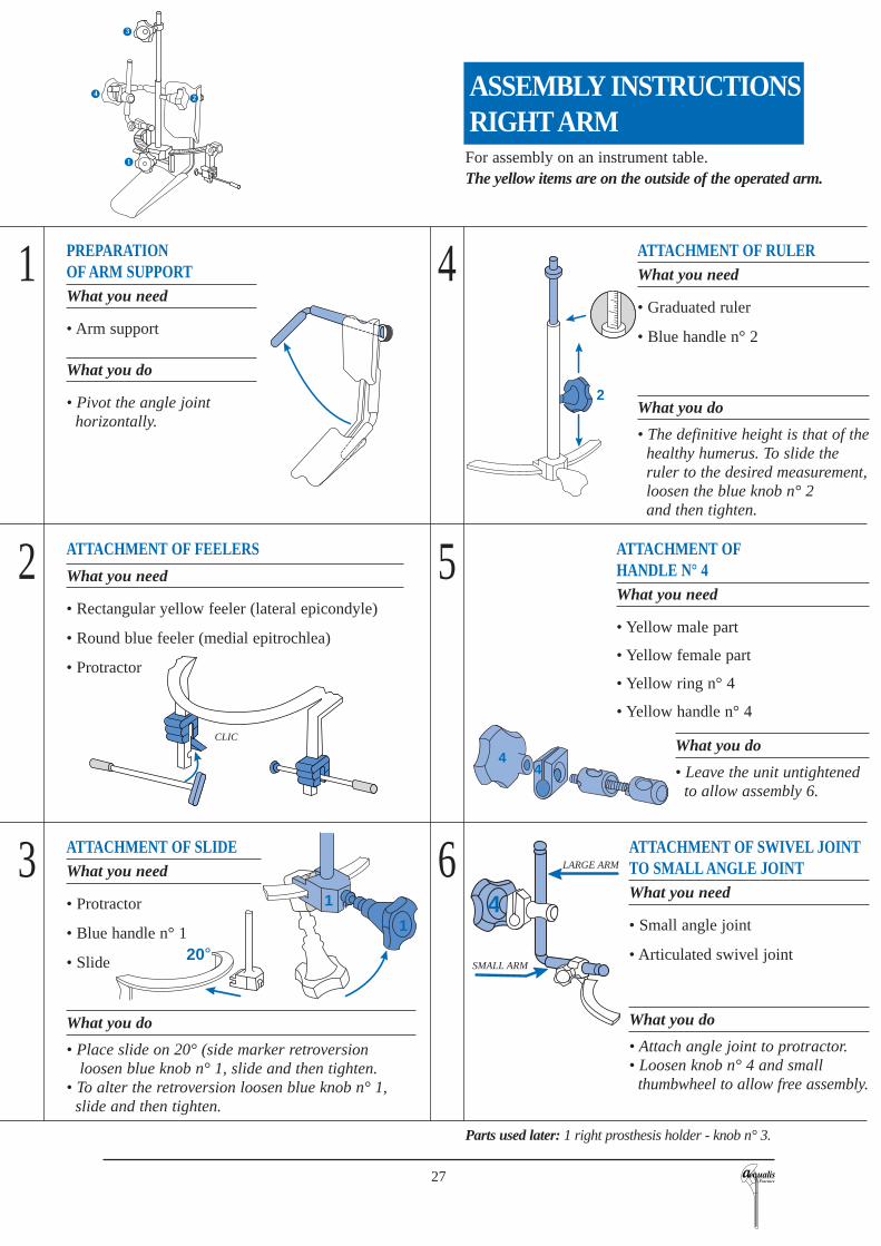
ASSEMBLY INSTRUCTIONSRIGHTARM
For assembly on an instrument table.The yellow items are on the outside of the operated arm.
1 4
2 5
3 6
27
ATTACHMENT OF SWIVEL JOINTTO SMALL ANGLE JOINTWhat you need
• Small angle joint
• Articulated swivel joint
What you do
• Attach angle joint to protractor.• Loosen knob n° 4 and small
thumbwheel to allow free assembly.
ATTACHMENT OFHANDLE N° 4What you need
• Yellow male part
• Yellow female part
• Yellow ring n° 4
• Yellow handle n° 4
What you do
• Leave the unit untightened to allow assembly 6.
ATTACHMENT OF RULERWhat you need
• Graduated ruler
• Blue handle n° 2
What you do
• The definitive height is that of thehealthy humerus. To slide the ruler to the desired measurement,loosen the blue knob n° 2 and then tighten.
PREPARATIONOF ARM SUPPORTWhat you need
• Arm support
What you do
• Pivot the angle jointhorizontally.
ATTACHMENT OF FEELERS
What you need
• Rectangular yellow feeler (lateral epicondyle)
• Round blue feeler (medial epitrochlea)
• Protractor
ATTACHMENT OF SLIDEWhat you need
• Protractor
• Blue handle n° 1
• Slide
What you do
• Place slide on 20° (side marker retroversion loosen blue knob n° 1, slide and then tighten.
• To alter the retroversion loosen blue knob n° 1,slide and then tighten.
Parts used later: 1 right prosthesis holder - knob n° 3.
LARGE ARM
SMALL ARM
CLIC
3
24
1

INSTRUMENTATION
1
2
3
45
6
7
8
0 1 2 3 4 5 6 7 8 9 10 11 12 13 14 15 16 17 18 19 20
2 3 4 5 6 7 8 9 10 11 12 13 14 15 16 17 18 19 20 21 22 23 24 25 30 35 40
28
FRACTURE JIG AEQUALIS-FRACTURE COMMON INSTRUMENT SET
Bone graft cutterRef. MWA301
Impaction supportRef. MWA302
Trial stemØ 6,5 mm Ref. MWA308Ø 9 mm Ref. MWA309Ø 12 mm Ref. MWA310
Ref. YKAD07
Cylindrical reamersØ 6,5 Ref. MWA046
Ø 9 Ref. MWA049
Ø 12 Ref. MWA052
Hexagonal screwdriver 4,5 mmRef. MWA119
Hexagonal screwdriver 3,5 mmRef. MWA120
MalletRef. MWA122
CaliperRef. MWA102
50 cm rulerRef. MWA123
OsteotomeRef. MWA101
Forceps for trial headRef. MWA103
Trial head39 x 14 Ref. MWA239
41 x 15 Ref. MWA241
43 x 16 Ref. MWA243
46 x 17 Ref. MWA246
48 x 18 Ref. MWA248
50 x 16 Ref. MWA250
50 x 19 Ref. MWA251
T handleRef. MWA106
Humeral prosthesis impactorRef. MWA108
Trial head templateRef. MWA110
Ref. YKAD12Ref. YKAD01 Ref. YKAD29
(Common instruments utilized in case of fracture)

INSTRUMENTATION
29
Ref. YKAD07
Inclination guideØ 6,5 Ref. MWA066
Ø 9 Ref. MWA069
Ø 12 Ref. MWA072
Implant broachØ 6,5 Ref. MWA026
Ø 9 Ref. MWA029
Ø 12 Ref. MWA032
Trial humeral stemØ 6,5 Ref. MWA006
Ø 9 Ref. MWA009
Ø 12 Ref. MWA012
Trial stem extractorRef. MWA118
Forceps for trial neckRef. MWA104
Trial neck125° Ref. MWA125
130° Ref. MWA130
135° Ref. MWA135
140° Ref. MWA140
Humeral prosthetis impactorRef. MWA109
Humeral cut protector125° Ref. MWA151
130° Ref. MWA152
135° Ref. MWA153
140° Ref. MWA154
Trial glenoid clampRef. MWA105
Curved glenoid template punchRef. MWA115
Straight glenoid template punchRef. MWA116
Trial glenoidSmall Medium Large
Ref. MWA202 Ref. MWA204 Ref. MWA206
Glenoid impactorRef. MWA107
Posterior glenoid retractorRef. MWA117
Impaction supportRef. MWA121
(Common instruments not utilized in case of fracture)

161, rue Lavoisier. 38330 Montbonnot. France. Tel. 33 (0)4 76 61 35 00. Fax: 33 ( 0)4 76 61 35 33.
E-mail: [email protected]
IMPLANTS
UD
AT
01.1
Head
Size Ref.37 x 13,5 DWB23737 x 13,5 DWB23937 x 13,5 DWB24137 x 13,5 DWB24337 x 13,5 DWB24637 x 13,5 DWB24837 x 13,5 DWB25037 x 13,5 DWB25152 x 15 DWB25252 x 23 DWB253
Humeral stem
Size Ref.Ø 6,5 DWB174Ø 9 DWB175Ø 12 DWB176
For more information, call toll free 1-888-TORNIER (867-6437)
or contact your local representative