Team Gannet - Florida Institute of Technologymy.fit.edu/~swood/Team Gannet Final Report.pdf · One...
40
Team Gannet By: Sam Maling and Andrew Verderame
Transcript of Team Gannet - Florida Institute of Technologymy.fit.edu/~swood/Team Gannet Final Report.pdf · One...
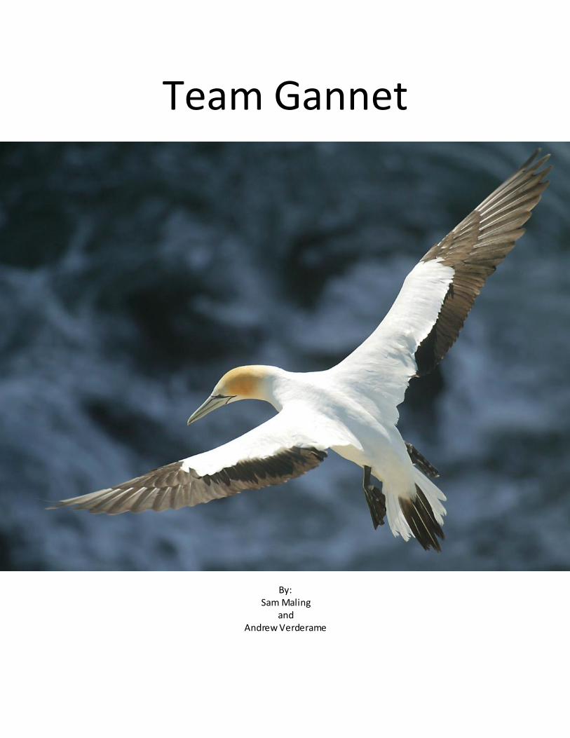
Team Gannet
By:
Sam Maling and
Andrew Verderame
T e a m G a n n e t | 2
Acknowledgements: Allan Shaw
Allan Shaw helped influenced our current design and helped us build our two models.
He also provided the construction materials and donated some hardware. He allowed
the Team Gannet to work out of his hanger and even donated some of his time to aiding
us in developing our models. Allan Shaw has been a huge influence on our team and
progress; we thank him and are sincerely grateful for his contributions towards the
team.
Dr. Stephan Wood
Dr. Wood donated the high density poly-urethane foam which was used to build our
model; he also donated some poly-ester resin which was used in the construction of our
first model.
DMES
Team gannet would like to thank the DMES Department (Department of Marine and
Environmental Systems) for funding this project.
Stephanie Hopper
The senior design team would also like to thank Stephanie Hopper for her donation to
the project and helping to fund some of the purchases made.
Bill Bailey
Bill Bailey helped with the making of the foam molds, converting the designs in Rhino to
MasterCam and helping us set up the tooling for both of the models, without his help
and machines, and we would not have been able to complete this project.

T e a m G a n n e t | 3
Table of Contents Acknowledgements 2 Executive Summary 4 Introduction 5-9 Motivation 5 Objective 5-6 Proposed Plan 6-9 Organization 9 Background 10-11 Basic Theory 10-11 Procedures 12-28 Customer Requirements 12-13 Engineering Specifications 14-17 Construction and Fabrication 17-25 Function Decomposition of Structure 25-28 Computer Models 28-29 Results 30-31 Discussion 32 Conclusion 33 Recommendation 34 Appendixes 35-39 References 40
List of Figures 1 Gannet Rhino Model ROV 1 6 2 Gannet Rhino Model ROV 2 6 3 Lockheed Martin “Cormorant” 13 4 Gannet ROV 1 Top Profile 14 5 Gannet ROV 1 Side Profile 14 6 Gannet ROV 1 Front Profile 15 7 Gannet ROV 2 Top Profile 16 8 Gannet ROV 2 Side Profile 17 9 Gannet ROV 2 Front Profile 17 10 Gannet ROV 1 Stepped Hull 26 11 Gannet ROV 2 Stepped Hull 27 12 Gannet ROV 1 Top Rudder 28 13 Gannet ROV 2 Bottom Rudder 28
List of Tables 1 Time Line of Gannet Construction 8 2 Team Members and Responsibilities 9 3 Gannet ROV 1 Specifications 15 4 Gannet ROV 2 Specifications 17
List of Abbreviations 1 MPUAV … Multi-Purpose Unmanned Arial Vehicle 2 ROV … Remotely Operated Vehicle 3 DARPA … Defense Advance Research Project Agency

T e a m G a n n e t | 4
Executive Summary:
The overall goal is to create a multi-purpose unmanned aerial vehicle (MPUAV) capable of both
flying in air and submerging underwater. This design will take off from a body of water, fly to an
intermediate destination and dive into the water. While underwater, it will travel to another
destination, where it will finally resurface. This cycle can repeat and multiple dives can be made in a
single use.
This project will draw on three different disciplines; ocean engineering, aerospace engineering,
and electrical engineering. Each major will be responsible for their own specific portion. The ocean
engineering students’ project is to design and construct a remotely operated vehicle (ROV), capable of
submerging underwater and resurfacing with enough speed for take-off; although, will focus specifically
on submerging, drainage of the fuselage, and hull planing. The aerospace engineering students will
design and construct the wings for Gannet. They will also determine the engine requirements and
design the systems that will control the craft while in air. In conjunction with the electrical engineering
students, the aerospace students will also construct a series of drop tests, measuring the forces on the
fuselage during impact with the water surface at various speeds. The electrical engineering team will
design and build the necessary electrical systems, the control methods, and programming of the
autonomous underwater controls. They will also construct a pressure housing and water proofing
methods for all components.

T e a m G a n n e t | 5
Introduction:
Motivations:
The motivation for the senior design project “Gannet” came from the personal goals of the team
members to design and build something new, and original. Each member wanted this project to have a
substantial impact on their careers after school, displaying their specific regions of their major that they
found most enjoyable and rewarding. The members wanted to build something that could one day
contribute to society, in collecting intelligence or data while saving valuable time.
Objectives:
It is the ocean engineering students’ project is to design and construct an ROV, capable of
submerging underwater and resurfacing with enough speed for take-off. This was accomplished using
skills acquired during the students’ career at Florida Institute of Technology and personal experience in
naval architecture and composite construction.
Multiple models were tested to evaluate different hulls and a comparison between them will be
compiled. One hull we have designed, built, and tested was influenced by sea planes, their stepped hull
allows them to plane at a steep angle allowing air to flow under the wings providing lift. A second model
that has been completed received influence from high speed small craft, utilizing a step in a hull to
reduce drag and improve acceleration in the transition from underwater travel to surface travel.

T e a m G a n n e t | 6
Figure 1: Gannet Rhino Model ROV 1 (Proved by Sam Maling)
Figure 2: Gannet Rhino Model ROV 2 (Proved by Sam Maling)
Purposed Plan:
In the beginning stages of planning and devising probable systems to solve the several problems
that plagued the group, a variety of solutions were developed. A large list was first compiled off all the
requirements the final prototype would need to fulfill. Working backwards from a finishing point the
group selected characteristics that the ocean engineering students could focus on as part of their senior
design project. Limited to submerging, underwater travel, transitioning to surface travel, and planning;
T e a m G a n n e t | 7
the ocean engineering students set out to begin drafting designs that could potentially fulfill the
requirements. The entire cast of student’s part of Team Gannet then discussed the designs that were
generated by Sam Maling and compare them to find a viable solution that reduced the forces on the
fuselage from diving into the water, allowed for a quick transition into submersed travel, and efficient
planning. The design had to also be adaptable by aerospace students when they would take over the
project senior year 2010. They required a platform for their design that would facilitate the transition
into flight. To do so, meant that the hull of the vessel would have to provide enough lift on plane to
elevate the wings from the water’s surface, generate enough lift under its wings for take-off.
Once designing of the first model is completed, it will be taken from Rhino; modeling software
that is capable of rendering curves, surfaces and solids (Rhinoceros), and transferred to MasterCam X;
another modeling program that writes programming the CNC machine; (Computer numerically cutting),
requires to operate and cut the molds. The construction process will then begin as soon as the first cut is
made in the foam block, from there on it will take several weeks to complete the model, transforming a
solid block of foam into a sleek shell that is the first model of Gannet. Once the model is completed and
fitted with the numerous electrical components such as; motors, electric speed controls (ESC), receiver
and batteries, it will be ready to test. The testing period is expected to last a few days, and will focus
specifically on submerging, planning and the transition between the two. The tests will be judged based
on the efficiency of the craft by visual inspection since the group has no instruments prepared to
analytically collect data. The tests will be designed to exploit any weaknesses in the design and
construction of the craft, identifying any flaws.
A second model will then be designed and constructed, the new model will be designed with a
different hull and any flaws that were identified in the last model will be improved upon in this second.
Again the design will make its way from a Rhino file and converted into MasterCam X were it will again
follow a similar construction process as the first model, taking shape after a few weeks of cutting and

T e a m G a n n e t | 8
glassing. However with the new model, different methods of construction may be applied to explore
options such as vacuum bagging, improving the strength of the hull. Testing of the second model will
then be completed using the same tests that were used on the first model, video footage of the tests
will help the students compare the designs and aid them in deciding which model is preferred to be
handed over to the aerospace engineers at the end of the summer semester 2010.
The models completed over the duration of the two semesters will provide substantial proof
that a submersible aircraft is possible and students from Florida Institute of Technology have laid a
platform that aerospace engineers can adapt to fly. The ocean engineering senior design program for
Sam Maling and Andrew Verderame will end after the summer symposium July 21st 2010, where the
project will be handed over the electrical and aerospace engineer’s part of Team Gannet. They will then
manage the project developing designs and models that are heavily influenced by the success of the
Sam Maling and Andrew Verderame. They will have until spring semester of 2011 to design, build and
test a prototype that will be revealed at the senior design showcase.
Table 1: Time Line of Gannet Construction
Task
Estimated Time Start Date
Design ROV 3 months
January 11th 2010
CNC Foam for ROV Mold 2 weeks
March 31st 2010
Construct Model from Mold 4 weeks
April 7th 2010
Install Internal systems into Model
1 week April 22nd 2010
Drop Test 1 week
April 25th 2010
Drag Test 1 week
May 17th 2010
Deign of ROV 2 2 weeks May 24th 2010
MFP Cruise 4 days June 8th 2010

T e a m G a n n e t | 9
CNC Foam for ROV 2 Mold 2 weeks June 12th 2010
Construct Model from ROV 2 Mold
2 weeks June 28th 2010
Testing of Second Model 1 week July 12th 2010
Senior Design Symposium 1 day July 21st 2010
Organization:
The responsibilities of the team members; Sam Maling, and Andrew Verderame have been
divided up based on their concentrated skill and prospective career choice in ocean engineering. Sam
has been chosen as team leader and has been put in charge of design, systems testing and internal
systems to be placed in model. Andrew has offered to be in charge of construction and testing. Each
team member will contribute equally to writing assignments and reports.
Table 2: Team Members and Responsibilities
Team Member Role Topics Major
Sam Maling Team Lead (OE) Designer Lead Researcher Fabrication
Naval Architecture Ocean Engineering
AJ Verderame Lead Fabricator Researcher Technician
Coastal Structures Ocean Engineering

T e a m G a n n e t | 10
Background:
Basic Theory:
Incorporated in the design of the first model, is a flooding and draining system that will help to
submerge the vessel, and help to return it to the surface allowing it to empty its ballast and plane. This
theoretical system was developed to the use of a dynamic ballast system to help decrease the buoyancy
of the craft in order to sink it. However with the model negatively buoyant, the same system must be
able to drain itself. This was all accomplished using holes cut in the steps of the hull. Modeled after a sea
plane, the dual steps helped to reduce drag and increase the angle of attack once up on plane, these
steps also create a low pressure at speed. With water under the hull, air is sucked under the step from
the surface and drag is effectively reduced because less of the hull is in contact with the water. With
holes drilled at the step, water would be allowed to fill the fuselage when the models speed dropped
enough to lower the hull and increase the surface area in contact with water. However as the model
moves and develops speed, water will drain though the low pressure at the steps until no more water
exists. Water will continue to exit at an exponential rate as the fuselage rises from the water because
gravity will continue to force water out through the steps.
The fully flooding fuselage was used to obtain negative buoyancy. This will allow Gannet to dive
at greater depths without the risk of pressure related damage, such as implosion. The electronics and
motors in the hull will be kept in a waterproof pressure housing to protect them from the water. This
will be made possible through the addition of inlets and outlets in the hull to allow water to flow in and
out of the vehicle.
In the second model, the flooding system was negated, and a ratio was made between total
displacement of the craft and its overall weight. With slightly positive buoyancy, the craft could still sink
itself with the aid of propulsion and trim tabs, pushing the model underwater. Sustained submersed
travel could then be maintained with the same hardware as long as there was enough fluid flow of the

T e a m G a n n e t | 11
trim tabs. If the vessel were to stop moving, the positively buoyant fuselage would rise to the surface
and rest at a stable waterline, which was still effecting at planning efficiently.
We will control both Gannet ROV 1 and ROV 2 in air and water using the same features. The
horizontal stabilizers or trim tabs will be used to control the ascent and descent of the vehicle, while the
vertical stabilizer or rudder, will be used to steer the craft from side to side. Using these controls, we will
have complete control of the vehicle at all times.

T e a m G a n n e t | 12
Procedures:
Utilizing the multiple perspectives this project is being approached by from the three disciplines,
Team Gannet was able to draw upon the ideas and capitalize on opportunities towards the design of the
model. Several of the systems present in the model are designed to be as simple as possible, reducing
points of failure. Yet throughout the initial design process, there were too many unanswered question
that the team could not solve without testing a model. There were disagreements on designs and the
theory behind the prospected ideas developed between team members. Although, with each problem
overcome, some opportunities were found and utilized to increase the success of the project.
Customer Requirements:
Gannet is to be a submersible aircraft, and also a DARPA (Defense Advance Research Project
Agency) challenge. The challenge offered by DARPA is to build a vehicle that can travel in air and
underwater for specified lengths of time while carrying soldiers and materials. Gannet may not be able
to carry any materials of humans; although, the team hopes that it will be capable of housing
instruments for surveying; such as, side scan sonar, depth gauge, current meter, and other additional
devices. The potential application of these instruments could expand the market for a vehicle such as
Gannet, making it applicable to oceanographic research as well as the potential for military survey.
Being able to be deployed from a boat, and then fly to an intermediate destination where it can
autonomously collect data from a pre-programmed path can save money that would have been spent
on research vessels. Oceanographic researchers would have the ability to collect data overnight without
ever setting foot on a research vessel. Gannet will be made for simplistic operation, asking the user to
enter a desired path and when to deploy specific measurement devices to collected required data. The
system will be user friendly and one day will become a reality, available to the public. Another potential
application for Gannet is reconnaissance as a military drone. Currently Lockheed Martin has developed
their version of a submersible aircraft that is launched from a submarine. This four ton vehicle then

T e a m G a n n e t | 13
performs reconnaissance returning to the sub via a separate ROV system. Their MPUAV (multi-purpose
unmanned aerial vehicle) “Cormorant” is dragged back to the sub for re-deployment. Gannet has been
designed to submerse itself, making it completely independent of any outside system. It will
autonomously be able to return to the sub under its own power, making it ideal for stealth and will not
heed the movements of the submarine, helping to maintain the secret of its location.
Figure 3: Lockheed Martin “Cormorant” (Provided by Zerohostel.com)
Gannet for now however will be proof of concept only, for the ocean engineering students, it
will only plane on the water’s surface, submerge on command and will transition quickly between the
two mediums. The models have been designed with the fewest number of systems and components to
test the possibility of such a radical invention. Gannet must float on the water’s surface, where it must
be able to maneuver quickly and without hesitation. From the water’s surface the model must dive or
sink, submerging itself quickly, and then be maneuverable underwater, with precision control in vertical
depth and horizontal travel. The model must then be able to bring itself to the surface and repeat the
process any number of times without fault. This description of requirements set by the members of
Team Gannet allows for a fuselage to be built with specific hardware attached, such as: a rudder, trim
tabs and motors and the necessary electrical supporting systems to provide power. By limiting the
systems installed, it allows for fewer failure points and provides a sturdy platform for developing a
design capable of succeeding.

T e a m G a n n e t | 14
Engineering Specifications:
Gannet ROV 1:
The constructed model of Gannet ROV 1 was built according to the maximum dimensions
allowed in the largest CNC machine at the machine shop on FIT campus. This was done to reduce the
amount of machine time required and expedite the mold making process. Specific dimensions can be
found in the appendix of this report, detailed drawings done in Rhino modeling software.
Figure 4: Gannet ROV 1 Top Profile (Proved by Sam Maling)
Figure 5: Gannet ROV 1 Side Profile (Proved by Sam Maling)
T e a m G a n n e t | 15
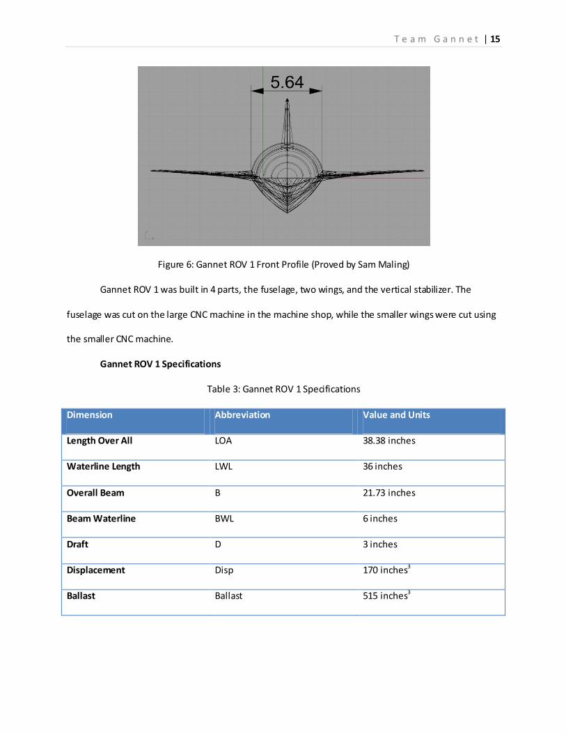
Figure 6: Gannet ROV 1 Front Profile (Proved by Sam Maling)
Gannet ROV 1 was built in 4 parts, the fuselage, two wings, and the vertical stabilizer. The
fuselage was cut on the large CNC machine in the machine shop, while the smaller wings were cut using
the smaller CNC machine.
Gannet ROV 1 Specifications
Table 3: Gannet ROV 1 Specifications
Dimension Abbreviation Value and Units
Length Over All LOA 38.38 inches
Waterline Length LWL 36 inches
Overall Beam B 21.73 inches
Beam Waterline BWL 6 inches
Draft D 3 inches
Displacement Disp 170 inches3
Ballast Ballast 515 inches3

T e a m G a n n e t | 16
Gannet ROV 2:
The second model designed and constructed for the senior design project was designed slightly
larger than the previous model, stretching the limits of the tooling accessible to the engineering
students on campus. Gannet ROV 2 was cut on the CNC machine on Florida Tech’s campus in three
sections. The fuselage was cut from a single large block of foam, and the wings were cut together from a
second block of poly-urethane foam donated by Dr. Stephan Wood of DMES department. Rhino
drawings below show the three perspectives along with some of the dimensions.
Figure 7: Gannet ROV 2 Top Profile (Proved by Sam Maling)
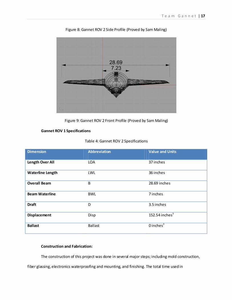
T e a m G a n n e t | 17
Figure 8: Gannet ROV 2 Side Profile (Proved by Sam Maling)
Figure 9: Gannet ROV 2 Front Profile (Proved by Sam Maling)
Gannet ROV 1 Specifications
Table 4: Gannet ROV 2 Specifications
Dimension Abbreviation Value and Units
Length Over All LOA 37 inches
Waterline Length LWL 36 inches
Overall Beam B 28.69 inches
Beam Waterline BWL 7 inches
Draft D 3.5 inches
Displacement Disp 152.54 inches3
Ballast Ballast 0 inches3
Construction and Fabrication:
The construction of this project was done in several major steps; including mold construction,
fiber glassing, electronics waterproofing and mounting, and finishing. The total time used in

T e a m G a n n e t | 18
construction from computer designing to testing took approximately two and a half months. After
designing and building the first model, we decided we could build a better revised model. The hull of our
first model was completed well before the senior design showcase in the spring. After repeated testing,
we determined the model was insufficient to suit our needs. We decided to build a second model using
the same basic steps as the first.
During the spring semester, the first part of the construction was started. Several group
members went to HobbyTown USA to purchase an R/C boat to be used for parts. We completely
stripped and gutted the boat of all hardware and electronics. We saved the hull for Dr. Wood so that it
may be used for future design projects and saved al l the parts we would need. We started to size up
what we had and what we would need so that we could start to put together our waterproof pressure
housing and what else we would need to buy to permit our vehicle to run underwater.
Immediately after the summer semester started, we began to build our second model. First we
obtained several boards of two-inch thick, high-density polyurethane foam from Dr. Wood. We learned
that the CNC machine (computed numerically controlled) in the Florida Tech machine shop could only
accommodate a 36-inch length cutting capacity. The CNC machine utilizes a cross-cutting drill bit tool to
carve out any non-inverted surfaces on the cutting medium. It is computer controlled to ensure perfect
and exact cutting. It is controlled using a modeling program called MastercamX. So, after learning its
limitations, we redesigned the length of the sketch to fit the foam in the machine. We used the band
saw in the machine shop to cut the foam boards to 42 inches so that they may be clamped on either side
during machining. Then, we glued three cut blocks together to make the final foam block six inches
thick. After that, we clamped the foam block to the bottom surface of the CNC machine. After the
MastercamX code was set up on the machine’s computer, the machine’s drill bit tool began to shave the
foam off of the block ¼ inch at a time using long, passing sweeps. Only one side of the hull could be cut
at one time because the only part of the machine that moves is the bottom surface where the foam

T e a m G a n n e t | 19
block was clamped. After one side was completely cut, we flipped the block and re -clamped it. Then we
had the tool cut the other side of the hull out of the foam. After the hull was completely cut out, we saw
that the top and bottom didn’t completely match up. So we decided to cut the hull in half and re-glue it
so it was perfectly aligned. Then we cut two more boards to 38 inches and glued them together. With
this new block, we cut out the two wings of the model, cutting one side at a time and flipping the block
to cut the other side. The last pieces we cut were the small triangular motor shaft struts that were later
mounted in the rear to allow the motor shafts to pass through the hull. Finally, we lined up the wings on
the sides of the hull and fastened them in place using three toothpicks on each side.
After the fabrication of the foam mold, we completely covered the entire hull with 2-inch
masking tape so the fiberglass wouldn’t stick. Then, using small circular motions, we coated the entire
taped surface with mold release, a wax-based; rub on paste that permits dried fiberglass to easily be
removed from many different surfaces. After two coats of the mold release were applied to the hull, we
applied three layers of fiberglass to the top of the hull. We applied these three coats in separate steps
and angles of the fiberglass to ensure superior strength throughout. We then let the fiberglass cure
overnight before we flipped the hull and repeated the process to the bottom of the hull. This process
left a defined and prominent ridge all along the sides of the hull. To remove this unsightly ridge, we
carefully grinded and sanded until smooth. Also left behind from the fiber glassing process were small
air bubbles and pockets, which were also sanded away. There was also a lot of print through of the
fiberglass strands that also needed to be sanded away to make the entire hull smooth.
As a small side project, we began to build the waterproof motor housing. We began by cutting
some one-inch PVC pipe to accommodate the motors. We custom cut the PVC pipe to the proper length
using a small hacksaw. After cutting the pipe, we primed and glued the pipe using PVC primer and
cement and holding it in place until it bonded. Then, we slid the motors in the pipe to determine where
the wire exit holes and exit water cooler pipes needed to be drilled. Finally we drilled the holes and
T e a m G a n n e t | 20
inserted the wires and pipes through the PVC end cap. To securely waterproof the wire and pipe holes,
we coated them with 3M 5200 Marine Sealant. This is a permanent adhesive that dries white and is
approved for waterproofing in almost any application. In the open end of the pipe we securely fasten a
circular aluminum plate to prevent grease from the other side from entering the motor. To make this
plate, we obtained some scrap aluminum plate from the machine shop so that we didn’t have to make
another purchase. We cut the aluminum plate on the band-saw in a perfect circle and drilled a hole in
the center to permit the motor shaft to pass through. Then, to securely fit the aluminum circle to the
inside of the pipe, we applied more 5200 to ensure a watertight seal. In the other end cap, we installed a
small brass bushing to prevent friction and the shaft from wearing the PVC away. On the other side of
the plate, we packed the pipe full of marine grade trailer bearing grease. We chose this grease because
of its resilience to heat and rotation and its ability to keep water out of what it’s packed in. After that,
we capped the end of the pipe with another PVC end cap and sealed it with PVC cement and 5200 to
make sure its waterproof.
After grinding the rough parts smooth on the hull, we cut the cured fiberglass in half along the
sides. We cut the six toothpicks in the wings to allow the hull mold to be removed and the wings to stay
in the hull for rigidity, strength and buoyancy. Then we removed the foam mold from the inside of the
hull. Next we cut six bulkheads from a pre-fabricated sheet of vacuum-bagged carbon fiber and
fiberglass. We cut four vertical bulkheads, three of which were used to support the hull from becoming
compacted, while the other one was used to support a large pressure chamber. The other two
bulkheads were used to horizontally support the large pressure chamber in the front of the hull. This
was designed to prevent the chamber from sliding forward and backward during the time when the
vehicle is under way. We then installed the bulkheads to the bottom of the hull using fiberglass tape.
Fiberglass tape is just plastic sheeting covered with fiberglass cloth and epoxy resin and cut in small

T e a m G a n n e t | 21
strips for easy application. After the tape was applied, we sanded and grinded the excess material off
using the air-powered grinder and sander.
Then, on the top half of the hull we cut the hatches so that we may access the inside of the
vessel when the two halves are joined. To do this, we drew a pattern on the surface and cut the hatches
out with an air-compressor powered reciprocating saw. It is a precision piece of machinery that is
capable of cutting any shape of any size with near perfect accuracy. Then we covered the cut-out hatch
doors with duct tape to allow for easy removal. After that, we fiber glassed around the hatch holes on
the inside surface of the hull to allow an apron so that it may be fastened down. After this layer had
dried, we removed the hatch and cut the excess length off using the same air powered reciprocating
saw. Then we sanded and grinded the rough spots, again using the air-compressor powered sander and
grinder. Finally, we riveted four nut plates onto the rear hatch apron and six nut plates onto the
forward hatch apron. This made it convenient and easy for the removal and attachment of the hatches
when they need to be moved.
The next part of the project consisted of mounting the motors to the bottom of the hull at the
appropriate angle and length. We decided that the best material for the motor mounts would be
Starboard, a marine-grade high density composite, resistant to most standard chemicals, heat and
sunlight. We cut the Starboard to small rectangular boxes to mount to the bottom of the hull. We used a
5-minute epoxy resin to fasten the Starboard to the hull so that we could just hold the mounts to the
bottom while it cured. Then, we used a plastic C-clamp to hold the motor housing to the Starboard and
we secured it down using stainless steel screws. We then drilled four small holes in the transom of the
vessel. Two holes were used to pass the rudder servo shafts through the hull from the servo bracket to
the rudder mounting plate, while the other two were used to pass the motor shafts from the motors to
the propellers. Finally we installed the rudder/ water cooling intake mount.

T e a m G a n n e t | 22
Next, we applied 5-minute epoxy resin to the underside of the hull where the motor shafts
would pass through. Once the epoxy hardened, we coated the foam pieces with a silicon powder and
epoxy mix. The silicon powder was used to strengthen the epoxy, as well as thicken it to resemble a
thick putty. Once the epoxy putty hardened, we installed the rear Arneson drives that we obtained from
the R/C boat we disassembled to allow the motor shafts to be properly supported. We then drilled two
more holes, one behind under each propeller, to run the water cooling system pipes out of the hull. We
chose this location because we needed an area of low pressure to permit the water from exiting the
system. As the craft moves, the spinning propellers create a low pressure where they drew water,
creating an ideal and convenient location.
The next part we worked on was the mechanical aspects of the wing. We needed a system that
would permit the craft to alter its depth while under way so we thought of an idea using the rear surface
of the wing to control depth. We obtained two eight-inch machined aluminum aircraft grade hinges and
riveted them to the back of the wings. To control the “flaps” moving up and down we chose to use small
waterproof servos. To mount these servos, we used the small air compressor powered reciprocating saw
to precisely cut the holes where the servos would fit in the wings. We then scooped out the foam from
the gaps and slid the servos in, guiding the wire under the foam to the inside of the fuselage. After lining
up where the servo arms should be mounted, we riveted the mounting arms to the aluminum flaps.
Next we cut and bent the servo rods to connect the servo arm with the servo mounting bracket on the
flap. This resulted in a one-piece, fully controllable control flap.
Next, we drilled holes in the inside vertical bulkheads to permit water flow and wires and water
cooling tubes to pass through. We used the drill attachment for the compressor and a 7/8-inch hole saw
to make the holes. We then mounted the internal rudder servo to the back bulkhead using 5-minute
epoxy and two small screws.
T e a m G a n n e t | 23
We cut the wires exiting the motor housing so that we may solder and seal them in separate
housing. We did this to reduce the amount of connections exposed to the air and water so there are less
points of failure available. To complete this task, we used wire cutters and strippers to cut and strip the
wires. Next we used a soldering pen and small gauge solder to permanently connect the wires together.
Finally, we sealed them by wrapping in electrical tape to prevent the wires from touching each other
and shorting out.
After that, we prepared to make the waterproof pressure housing to accommodate the
batteries, motor controllers, controller receiver, and transmitter. To do this, we cut a three-inch PVC
pipe to the appropriate length with a hacksaw. Next, we PVC cemented an end cap to one end and
drilled several holes to permit wires to come in, hoses to come in, and hoses to come out. We sealed the
wires and hoses in place using more 5200. At the other end of the pipe, we PVC cemented a threaded
open end cap. We needed to be able to access the chamber to remove components if necessary and to
charge the batteries. Then we wrapped the threads of the cap with PVC tape to make it more
waterproof and easier to screw on and off. Before closing the housing, we connected all of the
electronics. Finally, we screwed the lid in and set it in its holding bracket. This marked the final work of
the inside of the fuselage.
The next step consisted of joining the two halves. We began the process by slightly grinding the
leading edge each half to ensure a smooth transition after we fiber glassed them together and aligned
each half perfectly on top of each other. Next, we layed out the plastic material and applied three layers
of fiberglass cloth with epoxy resin and cut into 36-inch strips. Then we “taped” the two layers together
after initially coating the surface with more epoxy resin. We went around the entire body and applied
extra layers where we thought it looked a little thin. After the resin had hardened, we came back and
sanded and grinded the entire seam until there was no noticeable transition.

T e a m G a n n e t | 24
The next and final step of the construction of this craft was the finishing and painting. We began
by coating the top of the model with a silicon-thickened epoxy resin that had a consistency of warm
peanut butter. Once the top lay had dried, we flipped the model and repeated the process to the
bottom. This entire process was done to prevent the model from having small pinholes in the final
product. After this process, we had several small holes and indents that needed to be filled before
painting. These holes included one in the nose of the craft, one on the side of the wing, and one in the
stern. These holes and patches were the result of improper setting of the fiberglass. They dried with air
bubbles beneath the surface and required grinding away to attain proper shape and strength
characteristics. Once the bottom layer dried, we coated the top half with one layer of primer to prep
before painting. Again, once the top layer dried, we primed the bottom layer twice, as it required more
attention and filler before the final paint job was applied. Finally came the painting. We painted the
vessel using a high-gloss, marine grade paint. This particular paint was quite special, as it did not require
a gelcoat finish to produce a hard, enamel-like product. We applied the paint using a professional
industrial grade air compressor powered paint spraying gun. Using this piece of equipment permitted us
to paint in a fluent, easily transmissible pattern. We propped the model on four nails (two in the front
and two in the back) to reduce the amount of surface area exposed to the stand.
The final processes of the construction of the vehicle were just a few fine tunings and sealing of
several components. For example, we coated the installed wing flap servos with 5200 to hold them into
place. This layer of sealant also acted to make the exposed holes wore hydrodynamic, as well as to help
them be more waterproof. In addition, we went the machine shop to cut some thin aluminum plate in
to two small rectangles and bent them at 90-degree angles. Then we drilled a hole through either side of
the pieces. One hole was to mount the bracket to the rudder via a small stainless steel screw while the
other was used to insert the rudder servo shafts. We were going to make several holes on the top of the
vessel to allow water to enter to make it neutrally buoyant. We were also going to cut out the back side

T e a m G a n n e t | 25
of the hull step and make a hole in the transom to allow water to drain, but after testing we concluded
this was not necessary, as the model performed well without having to flood the fuselage.
Function Decomposition of Structure:
There are several unique features present in the designs and on the models of Gannet ROV 1
and ROV 2 that combine both worlds of flying and submerging. The ocean engineering students
developed two different hulls based off of Sea Planes and Intrepid Powerboats Inc. The addition of wings
are another special feature that are never seen on ROV’s until now, they were added to mimic the final
prototype to determine how they would affect the maneuverability of the models. Another feature
added that defines Gannet models are the encapsulated fuselage, this circular design is typically found
on submarines and airplanes, existing in both mediums it was a starting point for the team to design the
rest of the models.
The first model took advantage of a sea planes hull, the numerous steps they have allow them
to reduce drag on the hull while pitching the craft at a steep angle to allow air to flow under the wings
on take-off. This scenario was replicated in ROV 1, and was found to work well. As the vessel gains
speed, the change in draft between the steps allows for the buoyancy to decrease, dropping the stern
into the water and raising the bow above the water.
The hull was also designed with the goal to dive into the water and to accomplish this would
require influence from the gannet bird. Looking into nature, it was found that upon entry into the
water, the bird creates super-cavitation using its beak to break the water tension and generate a crater.
For Team Gannet to mimic this diving approach, we needed to design around the nose, building up
support structures and strengthening them with the correct materials. We chose to design the wings
similar to the space shuttle for two reasons; with the wings running along the entire fuselage, they are
much stronger than conventional wings and the added buoyancy at the tips of the wings helps to
provide more stability for the craft as it planes.
T e a m G a n n e t | 26
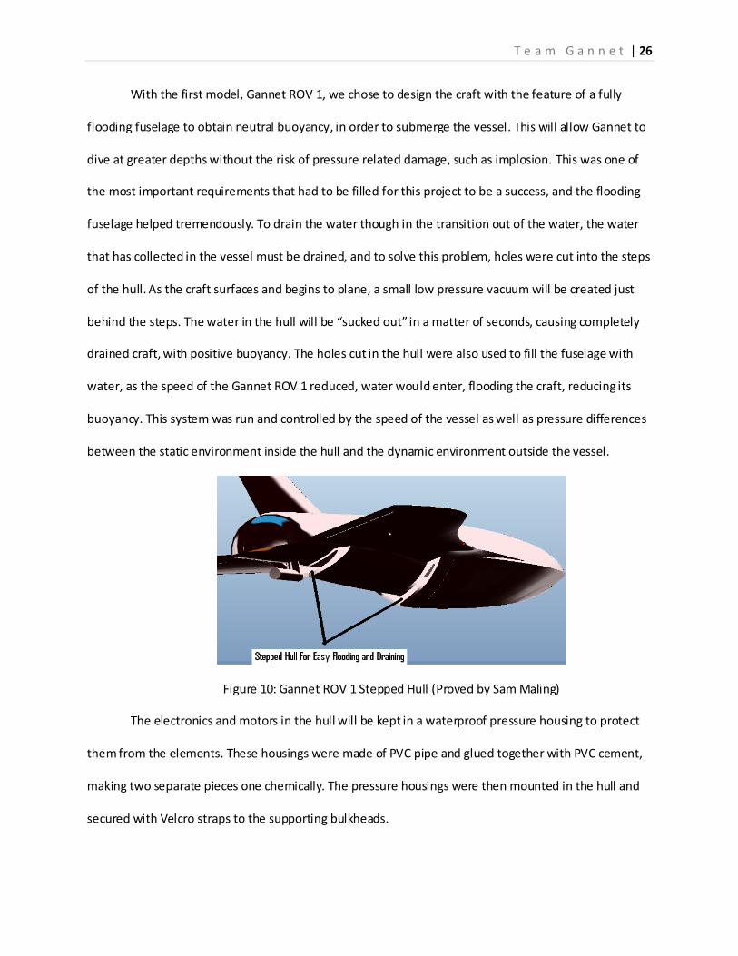
With the first model, Gannet ROV 1, we chose to design the craft with the feature of a fully
flooding fuselage to obtain neutral buoyancy, in order to submerge the vessel. This will allow Gannet to
dive at greater depths without the risk of pressure related damage, such as implosion. This was one of
the most important requirements that had to be filled for this project to be a success, and the flooding
fuselage helped tremendously. To drain the water though in the transition out of the water, the water
that has collected in the vessel must be drained, and to solve this problem, holes were cut into the steps
of the hull. As the craft surfaces and begins to plane, a small low pressure vacuum will be created just
behind the steps. The water in the hull will be “sucked out” in a matter of seconds, causing completely
drained craft, with positive buoyancy. The holes cut in the hull were also used to fill the fuselage with
water, as the speed of the Gannet ROV 1 reduced, water would enter, flooding the craft, reducing its
buoyancy. This system was run and controlled by the speed of the vessel as well as pressure differences
between the static environment inside the hull and the dynamic environment outside the vessel.
Figure 10: Gannet ROV 1 Stepped Hull (Proved by Sam Maling)
The electronics and motors in the hull will be kept in a waterproof pressure housing to protect
them from the elements. These housings were made of PVC pipe and glued together with PVC cement,
making two separate pieces one chemically. The pressure housings were then mounted in the hull and
secured with Velcro straps to the supporting bulkheads.

T e a m G a n n e t | 27
The stepped hull design is beneficial to the planning of the hull as well. The steps break the
suction of the surface of the water with the surface of the hull. This allows air to flow under the body of
the hull, greatly increasing top end speed, planning time, and performance.
The second model, Gannet ROV 2, design was based off of Intrepid Powerboat Inc. A
manufacture of small center console boats with an impressive background in performance, engineering
quality and naval architecture. The model showed the same “deep-V” type hull with a single step to
reduce drag and improve speed. The sharp hull improves handling and turning. The stern of the vessel
has a twenty-two degree angle which is steep enough to keep the boat from skipping in the water on
turns at high speeds and it also helps to displace water and improve the transition from underwater
travel to planning.
Figure 11: Gannet ROV 2 Stepped Hull (Proved by Sam Maling)
On the second model, the fuselage was designed not to flood like the first model, the students
had developed a second theory to sinking the model, using trim tabs and a conical shaped nose. The
trim tabs would help to push the bow down into the water, where the nose piece would deflect water;
pushing the vessel under, while maintaining positive buoyancy. This would only occur when the trim
tabs initiated the descent, and the model would return to the surface as soon as power to the motors
was cut. This new system seemed to be more promising because it had an integrated safety system

T e a m G a n n e t | 28
designed into it in case of any failure occurred. The model would have enough buoyancy to resurface if
control or power were lost.
On each of the models it was important to be able to access the electronics and hardware
mounted on the inside of the fuselage. To do this the engineers built hatches into the top of the fuselage
that could be access by removing a few screws.
On both models steering is an important issue that had to be overcome. It was initially thought
that a vertical stabilizer could be used, although it was found that it was insufficient on surface travel.
Without enough airflow of the rudder, the boat had little turning. In the second model a basic rudder
attached to the stern of the vessel and seamed promising. The problem with the rudder though is the
drag it creates when the model is getting up on a plane. This issue is a sacrifice that had to be made,
because the final prototype isn’t expected to land on land and clearance under the fuselage in not
Figure 12: Gannet ROV 1 Top Rudder Figure 13: Gannet ROV 2 Bottom Rudder
limited, a rudder or vertical stabilizer mounted on the underside of the craft will have to be used to
maintain stability and control when transitioning from water to air. The images below show the rudder
that was installed on the first model as well and the vertical stabilizer mounted in the first model.
Computer Models:
The computer generated designs were done using Rhino, a modeling software that is capable of

T e a m G a n n e t | 29
rendering curves, surfaces and solids and is used by several boat manufactures such as; Intrepid
Powerboats Incorporated, Regulator Marine and Boston Whaler. The completed designs were then
converted into Pro Engineer and MasterCam X. Pro Engineer is used by the aerospace engineering
students to design the wings and stabilizers; and will eventually be used to design their model.
MasterCam X was used to program the CNC machines, allowing the student to make an accurate model
of the proposed design. Images of Rhino can be seen attached to this report in the Appendix.
T e a m G a n n e t | 30
Results: Testing of the models proved to be successful based on visual inspection. There were no
measuring instruments used to quantify the movements of the models. The engineers would have like
to collect accurate speed recordings both above and below the water, while also timing the transition
between the submerged travel and surface planning. Some other values that would have helped
influence the success of the tests would be lift of the vessel while at plane, to determine the amount of
surface area the wings are subject to determine how much airflow they are influencing.
The tests between the two models were set to identify the success or failure of the
requirements set by the student engineers when designing was initiated. Each test was carried out over
both models for comparison of their performance, in three categories; underwater speed and
submerging efficiency, transition efficiency and surface planning and distance to reach plane. Although
the limitations of the first model prevented accurate testing.
The first model like the second model were first float tested to determine their waterline, their
displaced volume and initial estimates on their performance. With no motors or electronics, Gannet
ROV 1 was towed to determine how efficient it was at transitioning between the two modes of
transportation. The model Gannet ROV 2 had motors and was rigged for remote control, and was tested
using the system installed to evaluate its performance. The first model was also tested on its flooding
and draining capabilities, a system that was designed into the model as a solution to submerging the
craft. The second model however did not have the same system; instead it used a closed fuselage and
positive buoyancy, utilizing trim tabs to submerge the vessel. The systems on both models were tested
and judged by visual inspection and compared using video footage and notes taken during the testing
period.
Gannet ROV 1 showed promising results, succeeding in completing the requirements set by the
students, the overall success of the model roved that the beginning stages to developing a prototype for

T e a m G a n n e t | 31
a submersible aircraft. The models flooding and draining system was an accomplishment, although it
had its flaws. If control or power were lost during operation of the model, the vessel would sink very
quickly. If tested in the ocean or any other body of water other than a pool, recovery would be almost
impossible; a major concern for the engineers and another solution would have to be found to
submerge the vessel. The hull did perform well, its flat bottom and dual step helped to reduce drag and
deflect water helping the model get up on plane at a low speed. Another issue that arose in testing was
the size of the hatches, which don’t influence the performance of the model, but did have an impact on
the accessibility of tooling and maintenance.
Improvements made on the second model were included in the design of Gannet ROV 2, which
was then tested with major success. The control surfaces proved to provide substantial control over
vertical depth of the model, much more so than the negatively buoyant Gannet ROV 1. The second
model also had a recovery system built in, being positively buoyant, if power or control were cut, the
craft would resurface without any incorporation of a secondary system. The hull of Gannet ROV 2
helped to provide more stability, greater speeds both under water and on the surface, while improving
turning radius.
Results from the tests showed that while both models succeeded in performing their
requirements, the second model was chosen to be passed on to the aerospace and electrical
engineering students fall semester of 2010. The second model outperformed the fist and proved to have
more control, safer operation and faster in transition between being submerged to planning because of
the hull design and positive buoyancy. The second model with its water proofed electronics helped to
test the creative solutions the engineering students developed that can also be applied to the models
that will be designed and constructed during fall 2010 and spring 2011 semesters.

T e a m G a n n e t | 32
Discussion:
From the testes completed, flaws were found through the meticulous attention to detain by the
team members and improvements were made to correct any problem that arose. It was important for
the ocean engineers to develop a model that was successful enough and fulfilled the requirements
before the project could be passed on to the other engineering major’s part of Team Gannet. The final
product that was chosen along with its development notes, experience and specification was the second
model; Gannet ROV 2. This model proved to outperform the expectations of the students upon testing
and the simplistic systems installed helped to reduce weight of the final model. The simple design and
specifications were also simple and could easily be integrated into the final prototype.
From observations in previous tests completed, the results proved to be promising towards
future tests and building a successful prototype by the end of spring semester 2011. Tests to come by
the aerospace and electrical engineers will enable addition systems to look at the stresses the fuselage
encounters and the use of accelerometers will be employed to determine forces on the body. From
future tests the team can recommend accommodations towards the model and design, continuing
progress in building a proof of concept for a submersible aircraft.
T e a m G a n n e t | 33
Conclusion:
In conclusion, from the tests completed, models constructed, and progress to date; the team
has completing its goal and objective for designing the ROV portion of an MPUAV. The ocean
engineering students have work incredibly hard to complete their design; construction and testing of
two individual models to insure that they saw success in their project and design concepts. Their effort
proved that such a system as a submersible aircraft is plausible. The work completed will provide a
sturdy platform for the following engineering students to continue from, developing a final prototype
that will perform as the bird Gannet does. By the spring senior design showcase of 2011, the
multidiscipline project will be revealed to the public and will have hopefully succeeded in developing the
first completed working model of a submersible aircraft. This achievement will be rewarded with
numerous patents, journal entries, and theses. The work to come will be an endeavor much like the
previous two semesters for the ocean engineers, although great individual success for the team
members of all three majors will be substantial. Sam Maling and Andrew Verderame are confident in
their project and completed designs, they are proud of their completed work.
T e a m G a n n e t | 34
Recommendations:
Much of the last semesters were spent debating on design issues, and how to accomplish an
almost impossible task in such a limited period of time. However with the recent progress made, the
team of ocean engineers can confidently say that they produced a working design and model, capable of
fulfilling the requirements they set for the senior design project. Time was a major factor in this project
and had to be spent wisely, something that was taken for granted this last semester. The spring
semester was used to develop designs and solutions to the numerous problems that initially plagued the
project. The summer semester was also used for some design, although a majority of the hours spent
working were devoted to the fabrication and construction the models and components. Some advice
the students have for their fellow team mates as they will take over the project coming this fall 2010, is
to manage time efficiently, accommodating for machine time, delivery of parts, budget shortages, and
accounting for mistakes and rebuilds.

Appendix:
Material List:
Gorilla Glue
Stainless Screws size 10 by ¼ inche
Connecting Rods
Servo Arms
4-40 Screws ¼ inche and ½ inche lengths
Marine Trailor Grease
Marine 16 Gauge wire 3 feet
PVC Pipe 1’and 3’ diameter
PVC endcaps four 1’ diamter, and a
3’ dimater
PVC 3’ pipe fitting
PVC Cement and Primer
Heat Shrink
Sauter
Aceton
Epoxy Resin
5 minute Epoxy
Marine Primer
Marine Paint white
Finishing aceton
Rags
Paper Towels
Popsickle Sticks
3M 5200
Staboard
Mold release wax
Polyester Resin
MEKP Hardner
9 oz Fiber Glass Cloth
12 oz Carbon Fiber Cloth
Protective gloves
Dust masks
Masking tape
Duck Tape
Plastic Sheeting
2 in Paint Brushes
Mixing Cups
Poly-Urethane Foam
Aluminum plating
Silicon Power
Chopped Fiber Glass
Various Sand Paper
Budget Report for Senior Design Team Gannet:
See Attached spreadsheet title “Team Gannet 2010 Budget Report”.
MSDS Sheets:
See Attached Sheets for MSDS sheets for materials used.
Construction, Testing and Model Photos:
All photos can be seen on attached CD titled “Gannet Senior Design Team Photos”. All photos were
taken by Sam Maling and Andrew Verderame.
Saefty Report:
Safety Plan

T e a m G a n n e t | 36
Team Gannet April 13, 2010
1.0 Safety Plan Report Overview
1.1.1 Project General Description (PGD)
Gannet is a submersible aircraft drawing on the skills of several different disciplines. On the
team are Ocean Engineers, Electrical Engineers and Aerospace Engineers working to bring two separate
worlds together into a single working prototype. Gannet will be able to take-off from the water’s
surface, fly to a specific location remotely, where it will then dive into the water, travel underwater for a
specified time autonomously before it resurfaces to repeat the cycle.
It is the Ocean Engineering student’s job to design and test the necessary systems that will allow
Gannet to plan on the water surface with enough speed to take-off. They are also responsible for the
design of a system that will flood the fuselage upon entry into the water, and drain it completely when
Gannet is to transition from water to air travel. In addition, underwater control and propulsion are
systems that must be designed and integrated into Gannet.
1.1.2 Hazard Analysis (HA)
Through-out this project, the members of the team will encounter several different building
materials that require protection. We are expecting to work with composite materials including; carbon
fiber, fiberglass, and the necessary resins and hardeners. The project will require the use of polyester
and vinyl-ester resins with MEKP catalyst. Other materials such as close-cell urethane foam, aluminum,
and woods will be used.
1.1.3 Human Safety Analysis (HAS)
The materials expected to use will require protection in the form of safety glasses, dusk masks
and or respirators, latex gloves and ear plugs. When working with a material the necessary protection
will be taken. The use of machinery will also require some protection and knowledge of the precautions
that must be taken when working with the specific machine. Each member has been trained for use in
the machine shop and has proper certification to use the machines.
1.1.4 Failure Modes and Effects Analysis (FMEA)
If there is an accident while working on our project at any location, MSDS sheets will be
available and proper procedures will be followed.
2.0 Project General Description
The Florida Institute of Technology senior design team Gannet, has begun research and
development of a submersible aircraft. It is the Ocean Engineering student’s project to design the
necessary systems that will allow a body to fully submerge underwater, travel some length while
submerged and then finally resurface with enough speed to take-off from the water surface.

T e a m G a n n e t | 37
The senior design project Gannet is a collaboration of three different disciplines, Ocean
Engineering, Electrical Engineering and Aerospace Engineering. Each major is responsible for specific
portion of the project, although it is required that each individual team help one-another in
accomplishing their tasks. The Electrical and Aerospace engineering students will take over next fall
semester where they will build the final prototype. It is the goal of Gannet to design and build a multi -
purpose unmanned aerial vehicle(MPUAV) capable of flying in air, and traveling underwater. The design
will take-off from a body of water, fly to intermediate destination, and dive into the water. While
underwater, it will travel to a second destination autonomously before it resurfaces to take-off again.
The current design of the ocean engineering students is to completely fill the fuselage with
water, creating neutral buoyancy. This will be accomplished with large holes cut into the steps built into
the hull of Gannet, with smaller holes strategically positioned on the top of the fuselage and in the stern
to allow air to escape, increasing the flood rate. Underwater travel will be accomplished with two
waterproof electric motors with flexible shafts and plastic propellers. Horizontal stabilizers in the wings
will provide stability and control in the vertical direction. The vertical stabilizer will act as a rudder
controlling Gannet in the horizontal direction. Electronics will be housed in a pressure chamber and all
systems will be mounted on aluminum brackets. The stabilizers will be controlled with servos and push
rods already water proof. Surfacing will occur when Gannet is driven to the surface, where gravity will
then begin to drain water through the steps, the electric motors will then begin to move Gannet
creating a large pressure difference between the static fluid within the fuselage and the moving
surrounding water. With enough weight lost, Gannet will have enough speed to plan.
The construction of the fuselage, wings and vertical stabilizer will begin with the development of
a mold cut of close-cell urethane foam using MasterCam X and one of the CNC machines in the machine
shop. Each mold will then be taped using masking tape, and then mold release will be applied.
Composite material will then be laid over the mold and allowed to set.
Stabilizers will be cut from the finished model and re-applied with aluminum hinges and
connected using the servos and push rods. Motors will be mounted on aluminum blocks with a flexible
shaft that runs to aluminum drives with plastic propellers.
Gannet will dive into the water and to design a nose cone that will aid in the transition from air
to water, testing must be completed. Using the first model of Gannet, strain gauges and accelerometers
will be positioned along the fuselage and wings with a circuit and a nine-volt battery to record the data.
From this data we can develop a computer model and begin designing nose cones that will create super-
cavitations, reducing the forces of impact Gannet will make with the water surface.
Testing will also be required to ensure that submerging and draining systems work properly and
planning is possible. This will be conducted in Indian River, with calm conditions and a tow line. Again
the use of strain gauges and accelerometers will be used to capture the data of the forces that are
applied to the model.
When testing is completed of the first model a second may be built and then handed over to the
other engineering student to be used to apply their projects to developing a prototype. Electrical

T e a m G a n n e t | 38
Engineers will be responsible for the electronics, pressure housing, and transmitting video back to the
controller. The Aerospace students will develop the wings and stabilizers using similar methods as the
ocean engineering students.
3.0 Hazard Analysis (HA)
3.1.1 Composite Materials
Fiber glass and carbon fiber are two composite materials that will be used in the construction of
Gannet. These materials will be used to build the fuselage, bulkheads, vertical and horizontal stabilizers,
internal supports for any instruments and systems. When using these materials, gloves will be worn to
help prevent fibers from piercing the skin, causing irritation.
3.1.2 Resins
Polyester and vinyl-ester resins are expected to be used for their specific properties. These
materials can be dangerous if the necessary precautions are not taken; we plan on wearing latex gloves,
safely glasses and respirators to ensure that we are not exposed to the fumes, or come in contact with
the resins. They can cause irritation of the skin, harmful to the lungs and potentially deadly if
swallowed.
3.1.3 Hardeners
MEKP catalyst is the hardener that we will be using through-out our construction, when using
this accompanied with the resins, we will use gloves, respirators and safety glasses, preventing any of
the material, before and after mixing with the resins from coming in contact with our skin.
3.1.4 Close Cell Urethane Foam
This foam will be used to build the molds needed to construct Gannet, it will be cut using CNC machines
in the machine shop, and will be finished with various degrees of sand paper to obtain the designed
dimensions. When working with this foam and machinery, safely classes will be worn at all times with
dust masks. It is can cause irritation if it comes in contact with the eyes and if inhaled.
3.1.5 Aluminum
Aluminum will be used for some of the internal supports, this material can be harmful because
of the sharp edges and the small particles that are produced when cut. We will use Safety classes when
working with this material and ear plugs depending on the machine being used to produce this part.
3.1.6 Wood
Wood is another material that can cause injury because of the edges, weight and small particle
produces when cut. Dust masks and eye protection will be used when working with wood.
3.2 Environment Impact Analysis

T e a m G a n n e t | 39
MSDS Sheets for the above materials are supplied in attached pages of this report.
4.0 Human Safety Analysis (HAS) 4.1 Personal Protection Equipment (PPE) While working with the many different materials and machines to shape Gannet, we will use a variety of personal protection equipment. We will use safety glasses for each activity, always wearing them while in the machine shop. A dust mask will be worn when working with the close cell urethane foam and wood. When working with the composite materials, resins and catalyst, respirators will be worn to protect the lungs from the harmful fumes, latex gloves will also be worn to protect our skin. 4.2 General Work Safeties The Ocean Engineering students will comply to all OSHA procedures with each working circumstances. 4.3 University Insurance For this design project, the students do not expect to use Gannet in a public space, and will not involve working with an outside business or school. 5.0 Failure Modes and Effects Analysis (FMEA)
5.1 Possible Failure Scenarios
When testing the model of gannet, it is possible that some things may go wrong, causing the test to fail. One concern is if Gannet loses connection with the controller, a second similar
concern would be if the model lost power.
5.2 Results of Failure Scenarios If Gannet were to lose connection with the controller, it is possible that the model will sink or be stuck in motion where it could run aground, causing damage to itself. The second possible failure scenario could result in Gannet sinking.
5.3 Failure Mitigation To prevent any of these failure scenarios, Gannet will be tethered to the boat, allowing it to perform as designed; although, have some control in retrieving the model if any of the scenarios were to occur.

T e a m G a n n e t | 40
Reference:
Intrepid Powerboats Inc.
Rhinoceros
Zerohostel.com