Basic Memory Management - Florida Institute of Technologymy.fit.edu/~vkepuska/ece3552/TI...
26
Basic Memory Management Introduction Memory management involves: • Defining system memory requirements • Describing the available memory map to the linker • Allocating code and data sections using the linker The latter two, along with the C6000 memory architecture are covered in this chapter. Defining memory requirements is very application specific and therefore, is outside the scope of this workshop. If you have any questions regarding this, please discuss these during a break with your instructor. Learning Objectives Outline C6416 Memory Architecture C6713 Memory Architecture Section → Memory Placement Technical Training Organization T TO C6000 Integration Workshop - Basic Memory Management 3 - 1
Transcript of Basic Memory Management - Florida Institute of Technologymy.fit.edu/~vkepuska/ece3552/TI...

Basic Memory Management
Introduction Memory management involves: • Defining system memory requirements • Describing the available memory map to the linker • Allocating code and data sections using the linker
The latter two, along with the C6000 memory architecture are covered in this chapter.
Defining memory requirements is very application specific and therefore, is outside the scope of this workshop. If you have any questions regarding this, please discuss these during a break with your instructor.
Learning Objectives Outline
C6416 Memory ArchitectureC6713 Memory ArchitectureSection → Memory Placement
Technical TrainingOrganization
T TO
C6000 Integration Workshop - Basic Memory Management 3 - 1
C6416 Memory Architecture
Module Topics Basic Memory Management..................................................................................................................... 3-1
C6416 Memory Architecture................................................................................................................... 3-3 C6416 Internal Memory ..................................................................................................................... 3-3 C6416 External Memory .................................................................................................................... 3-4 C6416 DSK Memory.......................................................................................................................... 3-5 What is a Memory Map? .................................................................................................................... 3-6
C6713 Memory Architecture................................................................................................................... 3-7 C6713 Internal Memory ..................................................................................................................... 3-7 C6713 External Memory .................................................................................................................... 3-8 C6713 DSK Memory.......................................................................................................................... 3-9
Section → Memory Placement...............................................................................................................3-11 What is a Section? .............................................................................................................................3-11 Let’s Review the Compiler Section Names .......................................................................................3-12 Exercise - Section Placement.............................................................................................................3-13 How Do You Place Sections into Memory Regions? ........................................................................3-15
1. Creating a New Memory Region (Using MEM) .......................................................................3-16 2. Placing Sections – MEM Manager Properties...........................................................................3-17 3. Running the Linker....................................................................................................................3-20
Optional Discussion...............................................................................................................................3-22 ‘0x Memory Scheme .........................................................................................................................3-22 ‘1x Memory Scheme .........................................................................................................................3-25
3 - 2 C6000 Integration Workshop - Basic Memory Management

C6416 Memory Architecture
C6416 Memory Architecture
C6416 Internal Memory The C6416 internal memory map consists of two parts, Level 1 and Level 2.
Level 1 consists of two 16K-byte cache memories, one program, the other for data. Since these memories are only configurable as cache they do not show up in the memory map. (Cache is discussed further in an upcoming chapter.)
Level 2 memory consists of 1M bytes of RAM – and up to 256K bytes can be made cache. (If a segment is configured as cache, it doesn’t show up in the memory map.) This is a unified memory, that is, it can hold code or data.
'C6416 Internal Memory0000_0000 Level 2
Internal MemoryLevel 1 Memory
Always cache (not in map)L1P (prog), L1D (data)
Level 2 Memory (L2)RAM (prog or data)Up to 256 KB can be cache C6416
L1P = 16 KBL1D = 16 KBL2 = 1 MB
C6416L1P = 16 KBL1D = 16 KBL2 = 1 MB
FFFF_FFFF
L2 RAMProg/DataCPU
EMIFA
EMIFB
ProgramCache
DataCache
Technical TrainingOrganization
T TO
C6000 Integration Workshop - Basic Memory Management 3 - 3

C6416 Memory Architecture
C6416 External Memory External memory is broken into 4 CE (chip enable) spaces: CE0, CE1, CE2, CE3, per External Memory Interface (EMIF), each up to 1Gbytes long. Each CE space can contain program or data memory using asynchronous or synchronous memories (more on this in the EMIF module).
y0000_0000 Level 2
Internal Memory
External (A2)
External (A3)
A000_0000
B000_0000
FFFF_FFFF
External (A0)
External (A1)
8000_0000
9000_0000
External (B2)External (B3)
6800_00006C00_0000
External (B0)External (B1)
6000_00006400_0000
L2 RAMProg/DataCPU
EMIFA
EMIFB
C64x memory details ...
ProgramCache
DataCache
Each EMIF has four rangesProgram or DataNamed: CE0, CE1, CE2, CE3
Remaining memory is unused
C64x Memory Details0000_0000 Level 2
Internal Memory
External (A2)
External (A3)
A000_0000
B000_0000
FFFF_FFFF
External (A0)
External (A1)
8000_0000
9000_0000
External (B2)External (B3)
6800_00006C00_0000
External (B0)External (B1)
6000_00006400_0000
1GB (64-bit)256KBDM642256KB
1MB
Internal(L2)
256MB (32-bit)
A: 1GB (64-bit)B: 256MB(16-bit)
External
C6411
C6414C6415C6416
Devices
Each device is differentSome have two EMIF's
EMIFA is 64-bits wideEMIFB is 16-bits wide
3 - 4 C6000 Integration Workshop - Basic Memory Management

C6416 Memory Architecture
C6416 DSK Memory Based on the C6416’s memory-map, how does the C6416 DSK use this map?
'C6416 DSK Block DiagramDaughter-CardDaughter-Card
Roomfor
ExpansionSDRAM
(16MB)
CE2
CE3
Flash ROM(512KB)
CPLDCE1
CE0
DSK uses both EMIFs (A and B)EMIFA
CE0 for SDRAMCE2 and CE3 pinned-out to daughter card connector
EMIFBCE1 for Flash Memory and CPLD (switches, LED’s, etc.)
L2 RAMProg/Data
(1MB)CPU
EMIFA
EMIFB
ProgramCache
DataCache
CE0
C6000 Integration Workshop - Basic Memory Management 3 - 5

C6416 Memory Architecture
Sidebar – Memory Maps There are a few ways to view the memory architecture in your system. One is to use a block diagram approach (shown at the top of the slide below). Another way, which is often more convenient is to display the addresses and “contents” of the memories in a table format called a Memory Map.
What is a Memory Map?
1 GB8000_0000CE0
A000_0000CE2
C6000CPU
SRAM
EMIF
B000_0000CE3
9000_0000CE1
1 GB
1 GB 1 GB
A Memory Map is atable representation
of memory… 8000_0000
9000_0000
B000_0000
A000_0000
0000_0000
1GB CE3
1GB CE2
1GB CE1
1GB CE0
1MB L2 SRAM
Technical TrainingOrganization
T TO
CPLD:LED’sDIP SwitchesDSK statusDSK rev#Daughter Card
EMIFA CE3: 256MBB000_0000
A000_0000
9000_0000
8000_0000
6C00_0000
6800_0000
6400_0000
6000_0000
0010_0000
0000_0000
Daughter CardEMIFA CE2: 256MB
EMIFA CE1: 256MB
SDRAM: 16MBEMIFA CE0: 256MB
EMIFB CE3: 64MB
EMIFB CE2: 64MB
Flash: 512KBEMIFB CE1: 64MB
CPLDEMIFB CE0: 64MB
Internal Peripherals or reserved
Internal Peripherals or reserved
Internal RAM: 1MBInternal RAM: 1MBTMS320C6416 C6416 DSK
Technical TrainingOrganization
T TO
3 - 6 C6000 Integration Workshop - Basic Memory Management
C6713 Memory Architecture
C6713 Memory Architecture The C6713's memory architecture is very similar to that of the C6416. We're going to highlight the differences here.
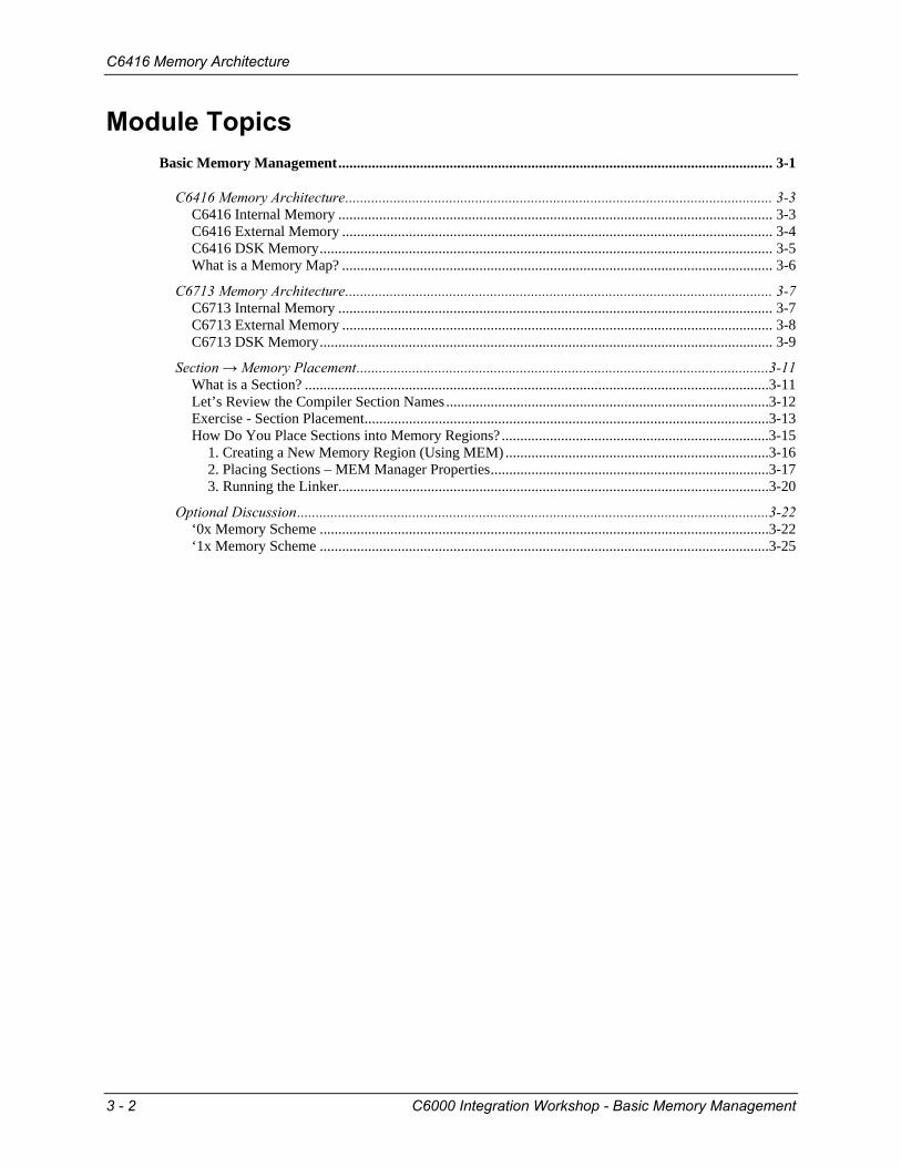
C6713 Internal Memory The C6713 has a two-level memory architecture just like the C6416. The Level 1 Caches are 4KB each (Program and Data). The Level 2 memory is 256KB, and up to ¼ of it can be made cache. You can actually add 16KB cache ways for up to a 4 way set-associative cache.
'C6713 Internal Memory0000_0000 Level 2
Internal MemoryLevel 1 Memory
Always cache (not in map)L1P (prog), L1D (data)
Level 2 Memory (L2)192KB RAM (prog or data)Up to 64KB cache
L2SRAM
prog/dataCPU
ProgramCache
DataCache
C6713L1P = 4 KBL1D = 4 KBL2 =256 KB
C6713L1P = 4 KBL1D = 4 KBL2 =256 KB
FFFF_FFFF
EMIF
What about the External Memory?Technical Training
Organization
T TO
C6000 Integration Workshop - Basic Memory Management 3 - 7

C6713 Memory Architecture
C6713 External Memory The C6713 has one EMIF with four external ranges. Each range has a dedicated strobe (CEx). The memory addresses that fall outside of the ranges are unused.
'C6713 External Memory0000_0000 Level 2
Internal Memory
FFFF_FFFF
Level 2Prog/DataCPU
ProgramCache
DataCache
External (CE2)
External (CE3)
A000_0000
B000_0000
External (CE0)
External (CE1)
8000_0000
9000_0000
EMIF
Four External rangesProgram or Data128 Mbytes eachNamed: CE0, CE1, CE2, CE3
Remaining memory is unused
How does this apply to the DSK?Technical Training
Organization
T TO
3 - 8 C6000 Integration Workshop - Basic Memory Management
C6713 Memory Architecture
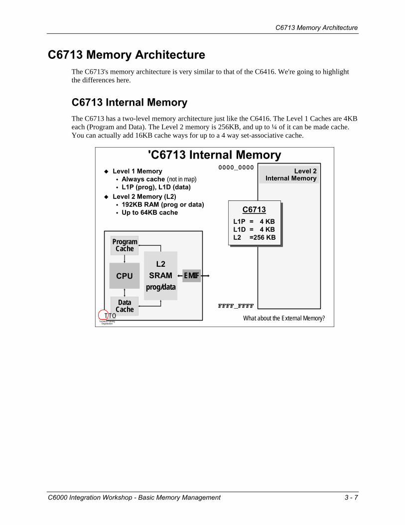
C6713 DSK Memory Here is a block diagram of the memory (internal and external) that is available on the C6713 DSK.
'C6713 DSK Block DiagramDaughter-CardDaughter-Card
Roomfor
Expansion
InternalMemoryCPU
ProgramCache
DataCache
EMIF
SDRAM(16MB)
CE2
CE3
Flash ROM(256KB)I/O Port
CE1
CE0
DSK uses all four External Memory regionsCE0 for SDRAMCE1 for Flash Memory and I/O Port (switches, LED’s, etc.)CE2 and CE3 pinned-out to daugher card connector
So what does the Memory Map look like?
One of the biggest differences between the two chips is that the C6713 only has one EMIF. The FLASH on the C6713 DSK is also 256KB, as opposed to 512KB on the C6416 DSK.
C6000 Integration Workshop - Basic Memory Management 3 - 9
C6713 Memory Architecture
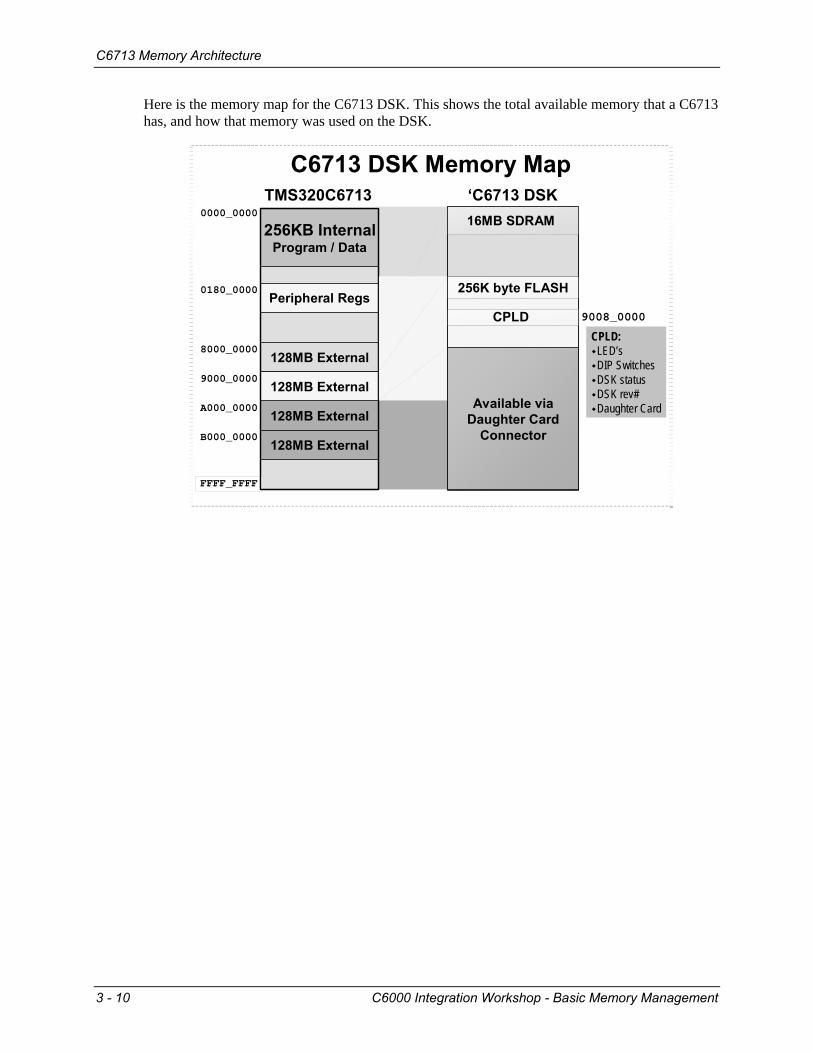
Here is the memory map for the C6713 DSK. This shows the total available memory that a C6713 has, and how that memory was used on the DSK.
FFFF_FFFF
0000_0000
256KB InternalProgram / Data
Peripheral Regs0180_0000
128MB External
128MB External
8000_0000
9000_0000
A000_0000
B000_0000
128MB External
128MB External
TMS320C6713
Available viaDaughter Card
Connector
‘C6713 DSK16MB SDRAM
256K byte FLASH
CPLD
C6713 DSK Memory Map
CPLD:LED’sDIP SwitchesDSK statusDSK rev#Daughter Card
9008_0000
3 - 10 C6000 Integration Workshop - Basic Memory Management

Section → Memory Placement
Section → Memory Placement
What is a Section? Looking at a C program, you'll notice it contains both code and different kinds of data (global, local, etc.).
Sections
short m = 10;short x = 2;short b = 5;
main(){short y = 0;
y = m * x;y = y + b;
printf("y=%d",y);}
Every C program consists of different parts called SectionsAll default section names begin with "."
Let’s review thelist of compiler
sections…
Global Vars (.bss) Init Vals (.cinit)
Local Vars(.stack)
Code(.text)
Std C I/O(.cio)
Technical TrainingOrganization
T TO
In the TI code-generation tools (as with any toolset based on the COFF – Common Object File Format), these various parts of a program are called Sections. Breaking the program code and data into various sections provides flexibility since it allows you to place code sections in ROM and variables in RAM. The preceding diagram illustrated five sections: • Global Variables • Initial Values for global variables • Local Variables (i.e. the stack) • Code (the actual instructions) • Standard I/O functions
Though, that’s not all the sections broken out by the C6000’s compiler …
C6000 Integration Workshop - Basic Memory Management 3 - 11

Section → Memory Placement
Let’s Review the Compiler Section Names Following is a list of the sections that are created by the compiler. Along with their description, we provide the Section Name defined by the compiler.
Compiler's Section Names
uninitializedBuffers for stdio functions.cio
uninitializedMemory for malloc fcns (heap).sysmem
uninitializedStack (local variables).stack
uninitializedGlobal and static variables.far
uninitializedGlobal and static variables.bss
initializedInitial values for C++ constructors.pinit
initializedInitial values for global/static vars.cinit
initializedGlobal and static string literals.const
initializedTables for switch instructions.switch
initializedCode.text
Memory TypeDescriptionSection
Name
Technical TrainingOrganization
T TO
If you think some of these names are a bit esoteric, we agree with you. (.code might have made more sense than .text, but we have to live with the names they chose.)
You must link (place) these sections to the appropriate memory areas as provided above. In simplest terms, initialized might be thought of as ROM-type memory and uninitialized as RAM-type memory.
3 - 12 C6000 Integration Workshop - Basic Memory Management

Section → Memory Placement
Exercise - Section Placement Where would you anticipate these sections should be placed into memory? Try your hand at placing five sections and tell us why you would locate them there.
Exercise
16MBSDRAM
8000_0000CE0
4MBFLASH
9000_0000CE1
C6000CPU
InternalMemory
Where would you place each
of these sections?
WhyLocationSection
.cio
.stack
.bss
.cinit
.text
Hint: Think about what type of memory each one should reside in – ROM or RAM.
C6000 Integration Workshop - Basic Memory Management 3 - 13
Section → Memory Placement
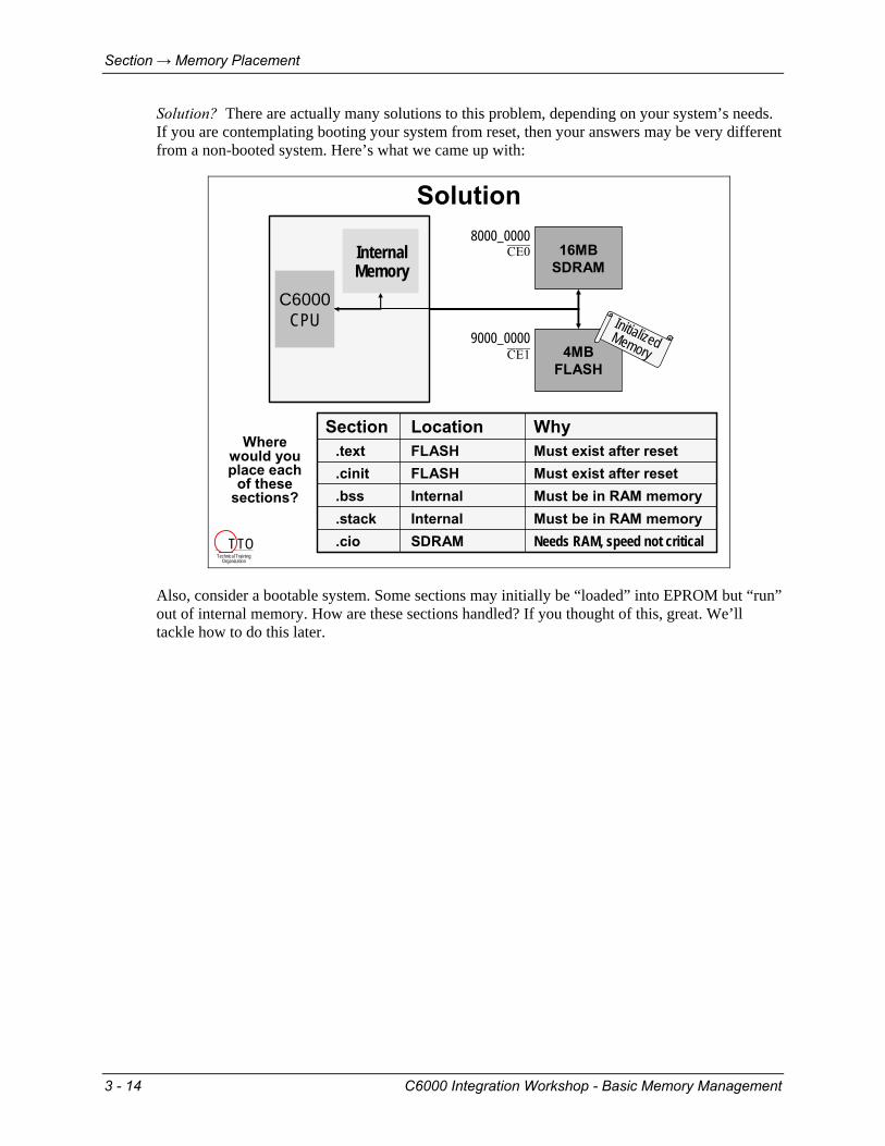
Solution? There are actually many solutions to this problem, depending on your system’s needs. If you are contemplating booting your system from reset, then your answers may be very different from a non-booted system. Here’s what we came up with:
16MBSDRAM
8000_0000CE0
4MBFLASH
9000_0000CE1
C6000CPU
InternalMemory
Solution
Where would you place each
of these sections?
WhyLocationSection
Needs RAM, speed not criticalSDRAM.cioMust be in RAM memoryInternal.stackMust be in RAM memoryInternal.bssMust exist after resetFLASH.cinitMust exist after resetFLASH.text
Initialized Memory
Technical TrainingOrganization
T TO
Also, consider a bootable system. Some sections may initially be “loaded” into EPROM but “run” out of internal memory. How are these sections handled? If you thought of this, great. We’ll tackle how to do this later.
3 - 14 C6000 Integration Workshop - Basic Memory Management
Section → Memory Placement
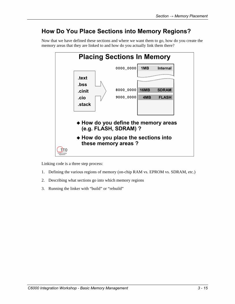
How Do You Place Sections into Memory Regions? Now that we have defined these sections and where we want them to go, how do you create the memory areas that they are linked to and how do you actually link them there?
Placing Sections In Memory
.text
.bss
.cinit
.cio
.stack
How do you define the memory areas(e.g. FLASH, SDRAM) ?How do you place the sections intothese memory areas ?
8000_0000
9000_0000 4MB FLASH
16MB SDRAM
1MB Internal0000_0000
Technical TrainingOrganization
T TO
Linking code is a three step process:
1. Defining the various regions of memory (on-chip RAM vs. EPROM vs. SDRAM, etc.)
2. Describing what sections go into which memory regions
3. Running the linker with “build” or “rebuild”
C6000 Integration Workshop - Basic Memory Management 3 - 15

Section → Memory Placement
1. Creating a New Memory Region (Using MEM) First, to create a specific memory area, open up the .CDB file, right-click on the Memory Section Manager and select “Insert MEM”. Give this area a unique name and then specify its base and length. Once created, you can place sections into it (shown in the next step).
Using the Memory Section Manager
MEM Manager allowsyou to create memoryareas & place sections
To Create a NewMemory Area:
Right-click on MEMand select Insert MemFill in base/len, etc.
How do you placesections into these
memory areas?
Technical TrainingOrganization
T TO
Note: The heap part of this dialog box is discussed later.
3 - 16 C6000 Integration Workshop - Basic Memory Management
Section → Memory Placement
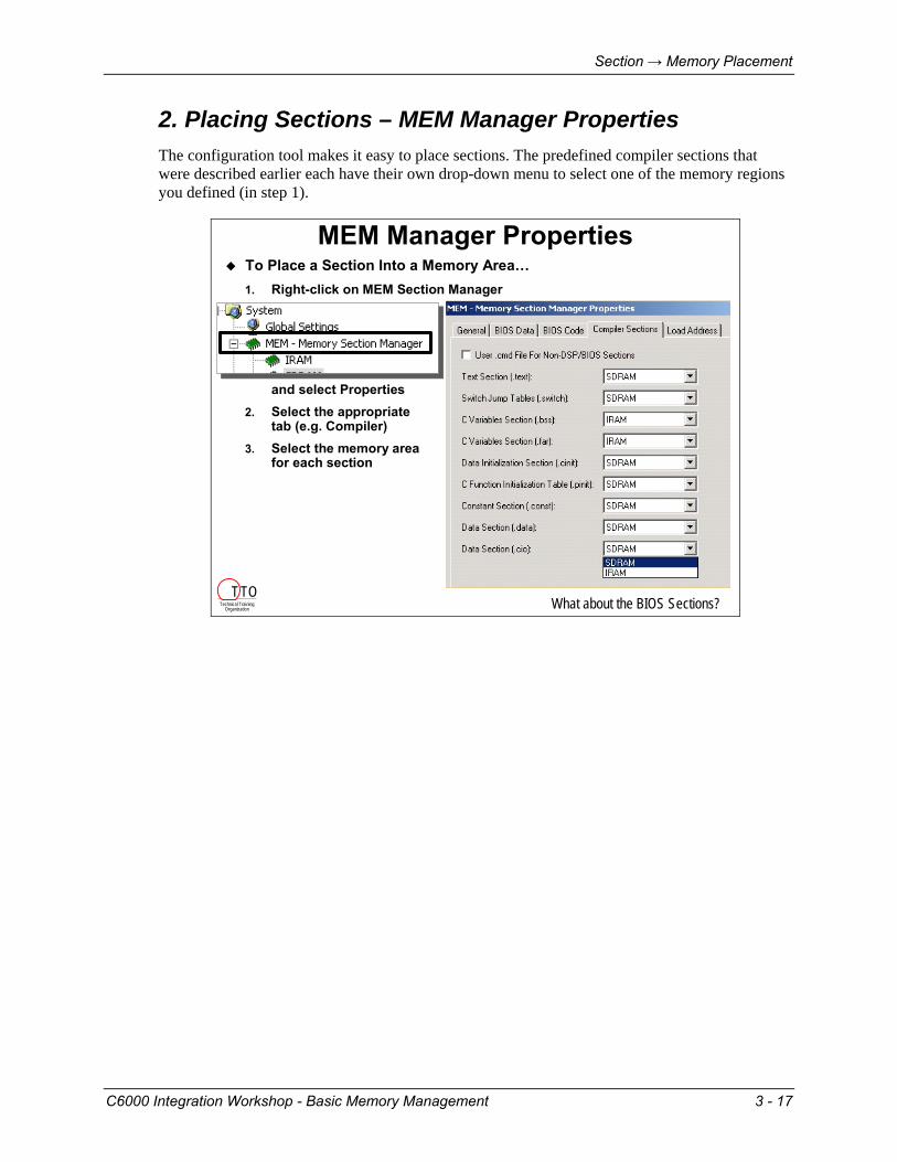
2. Placing Sections – MEM Manager Properties The configuration tool makes it easy to place sections. The predefined compiler sections that were described earlier each have their own drop-down menu to select one of the memory regions you defined (in step 1).
MEM Manager PropertiesTo Place a Section Into a Memory Area…1. Right-click on MEM Section Manager
and select Properties2. Select the appropriate
tab (e.g. Compiler)3. Select the memory area
for each section
What about the BIOS Sections?Technical TrainingOrganization
T TO
C6000 Integration Workshop - Basic Memory Management 3 - 17

Section → Memory Placement
There are 3 tabbed pages of pre-defined section names: (1) BIOS Data Sections (2) BIOS Code Sections (3) Compiler sections
Placing BIOS Sections
BIOS creates both Data andCode sections
User needs to place these into appropriate memory region
What gets created afteryou make these selections?
Technical TrainingOrganization
T TO
We haven’t had the opportunity to describe all the BIOS-related sections. Please refer to the online help for a description of each.
At times you will need to define and place your own user-defined sections, this is discussed later in the chapter.
3 - 18 C6000 Integration Workshop - Basic Memory Management

Section → Memory Placement
Initialized Sections Earlier we discussed putting some sections into initialized (ROM) memory. When debugging our code with CCS, though, we haven’t been putting these sections into ROM. How can the system work?
The key lies in the difference between ROM and initialized memory. ROM memory is a form of initialized memory. After power-up ROM still contains its values – in other words it’s initialized after power-up.
Therefore, for our system to work, the initialized sections must “exist” before we start running our code. In production we can program EPROM’s or Flash memory ahead of time. Or, maybe a host downloads the initialized code and data before releasing the processor from reset.
Initialized Memory
CPU
IRAM.out file
.bios .sysinit
.gblinit .trcdata
.hwi_vec .rtdx_text
.text .switch
.cinit .pinit
.const
CCS loader copies the followingsections into volatile memory:
Technical TrainingOrganization
T TO
When using the CCS loader (File:Load Program…), CCS automatically copies each of the initialized sections (.text, .switch, .cinit, .pinit, .const, etc.) into volatile memory on the chosen target.
Later in the workshop we will examine more advanced ways to locate initialized sections of code and data. We even will get a chance to burn them into a Flash memory and re-locate them at runtime. But for now, we won’t try anything that fancy.
C6000 Integration Workshop - Basic Memory Management 3 - 19
Section → Memory Placement
3. Running the Linker Creating the Linker Command File (via .CDB)
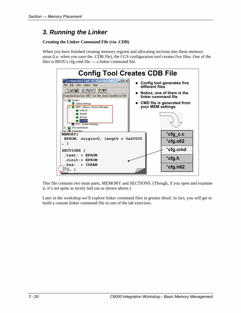
When you have finished creating memory regions and allocating sections into these memory areas (i.e. when you save the .CDB file), the CCS configuration tool creates five files. One of the files is BIOS’s cfg.cmd file — a linker command file.
Config Tool Creates CDB File
*cfg.h62
*cfg.h
*cfg.cmd
*cfg.s62*cfg_c.c
Config tool generates five different filesNotice, one of them is the linker command fileCMD file is generated from your MEM settings
MEMORY{EPROM: origin=0, length = 0x20000
… }
SECTIONS {.text: > EPROM.cinit:> EPROM.bss: > IDRAM
… }
MEMORY{EPROM: origin=0, length = 0x20000
… }
SECTIONS {.text: > EPROM.cinit:> EPROM.bss: > IDRAM
… }Technical Training
Organization
T TO
This file contains two main parts, MEMORY and SECTIONS. (Though, if you open and examine it, it’s not quite as nicely laid out as shown above.)
Later in the workshop we’ll explore linker command files in greater detail. In fact, you will get to build a custom linker command file in one of the lab exercises.
3 - 20 C6000 Integration Workshop - Basic Memory Management
Section → Memory Placement
Running the Linker
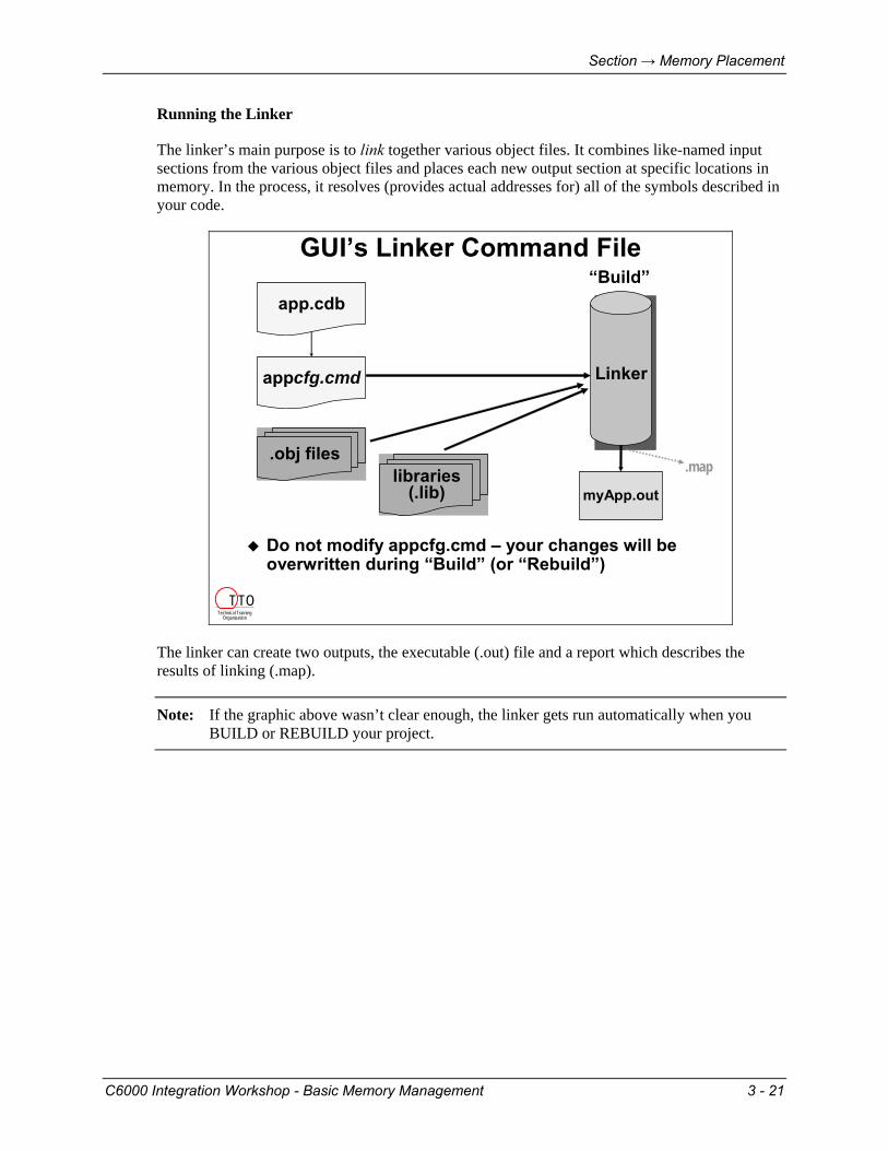
The linker’s main purpose is to link together various object files. It combines like-named input sections from the various object files and places each new output section at specific locations in memory. In the process, it resolves (provides actual addresses for) all of the symbols described in your code.
GUI’s Linker Command File
app.cdb
LinkerLinkerappcfg.cmd
myApp.out
Do not modify appcfg.cmd – your changes will beoverwritten during “Build” (or “Rebuild”)
“Build”
.obj fileslibraries
(.lib).map
Technical TrainingOrganization
T TO
The linker can create two outputs, the executable (.out) file and a report which describes the results of linking (.map).
Note: If the graphic above wasn’t clear enough, the linker gets run automatically when you BUILD or REBUILD your project.
C6000 Integration Workshop - Basic Memory Management 3 - 21
Optional Discussion
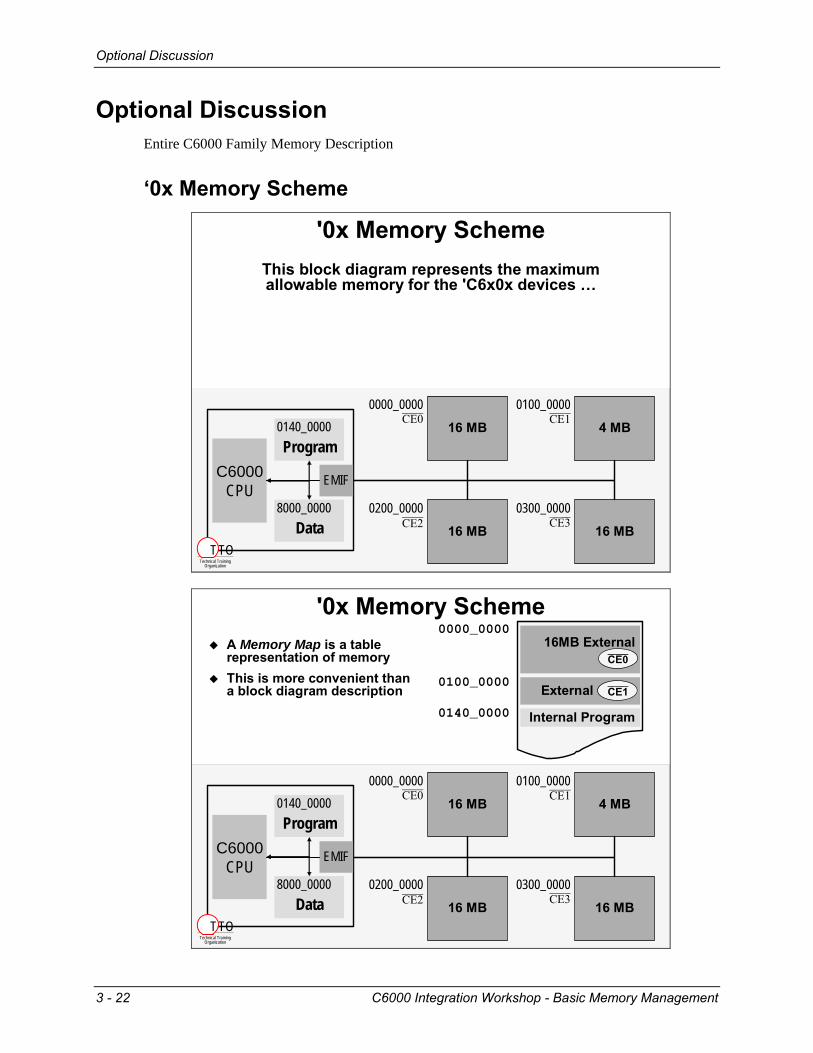
Optional Discussion Entire C6000 Family Memory Description
‘0x Memory Scheme
'0x Memory Scheme
16 MB
0000_0000CE0
4 MB
0100_0000CE1
16 MB
0200_0000CE2 16 MB
0300_0000CE3
C6000CPU
0140_0000Program
EMIF
8000_0000Data
This block diagram represents the maximum allowable memory for the 'C6x0x devices …
Technical TrainingOrganization
T TO
'0x Memory Scheme
16 MB
0000_0000CE0
4 MB
0100_0000CE1
16 MB
0200_0000CE2 16 MB
0300_0000CE3
C6000CPU
0140_0000Program
EMIF
8000_0000Data
0000_000016MB External
(CE0)
External (CE1)
Internal Program
0100_0000
0140_0000
CE0
CE1
A Memory Map is a table representation of memoryThis is more convenient than a block diagram description
Technical TrainingOrganization
T TO
3 - 22 C6000 Integration Workshop - Basic Memory Management

Optional Discussion
'0x Memory Scheme0000_0000
Internal Program
0100_0000
0140_0000
16MB External(CE0)CE0
4MB External (CE1)CE1
Internal Data
16MB External(CE0)CE2
16MB External(CE0)CE3
0200_0000
0300_0000
8000_0000
FFFF_FFFF
All '0x devices share same external memory mapCE0,2,3: 16M Bytes; allowsSDRAM, SBSRAM and AsyncCE1: 4M Bytes; allowsSBSRAM and Async only
Technical TrainingOrganization
T TO
'0x Memory Scheme
P = 384 KBD = 512 KB
C6203
P = 256 KBD = 128 KB
C6202
P = 64 KBD = 64 KB
C6201C6204C6205C6701
InternalDevices
All '0x devices share same external memory mapCE0,2,3: 16M Bytes; allowsSDRAM, SBSRAM and AsyncCE1: 4M Bytes; allowsSBSRAM and Async onlyInt Prog: Cache or RAMList of '0x devices with various internal mem sizes
0000_0000
Internal Program
0100_0000
0140_0000
16MB External(CE0)CE0
4MB External (CE1)CE1
Internal Data
16MB External(CE0)CE2
16MB External(CE0)CE3
0200_0000
0300_0000
8000_0000
FFFF_FFFF
Technical TrainingOrganization
T TO
C6000 Integration Workshop - Basic Memory Management 3 - 23

Optional Discussion
'0x Alternate Memory Map
MAP 0FFFF_FFFF
0000_0000
0200_000016M x 8External
2
16M x 8External
3
0300_0000
0100_0000
16M x 8External0
4M x 8External1
Internal Program0140_0000
Internal Data8000_0000
On-chip Peripherals0180_0000
16M x 8External
0
4M x 8External1
Internal Program0000_0000
0040_0000
0140_0000
MAP 1
Map 1 moves internal program to location zeroUsed for boot-loadingNo memory lost, only rearrangedEasy, drop-down selection between Map 0/1 with Config Tool
Map 1 moves internal program to location zeroUsed for boot-loadingNo memory lost, only rearrangedEasy, drop-down selection between Map 0/1 with Config Tool
Technical TrainingOrganization
T TO
3 - 24 C6000 Integration Workshop - Basic Memory Management
Optional Discussion
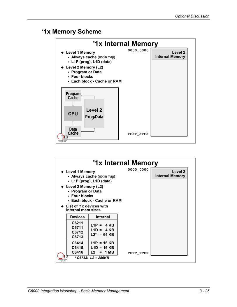
‘1x Memory Scheme
'1x Internal Memory0000_0000 Level 2
Internal Memory
FFFF_FFFF
Level 1 MemoryAlways cache (not in map)L1P (prog), L1D (data)
Level 2 Memory (L2)Program or DataFour blocksEach block - Cache or RAM
Level 2Prog/DataCPU
ProgramCache
DataCache
Technical TrainingOrganization
T TO
'1x Internal Memory0000_0000 Level 2
Internal Memory
FFFF_FFFF
Level 1 MemoryAlways cache (not in map)L1P (prog), L1D (data)
Level 2 Memory (L2)Program or DataFour blocksEach block - Cache or RAM
List of '1x devices with internal mem sizes
L1P = 16 KBL1D = 16 KBL2 = 1 MB
C6414C6415C6416
L1P = 4 KBL1D = 4 KBL2* = 64 KB
C6211C6711C6712C6713
InternalDevices
* C6713: L2 = 256KBTechnical Training
Organization
T TO
C6000 Integration Workshop - Basic Memory Management 3 - 25

Optional Discussion
'1x External Memory0000_0000 Level 2
Internal Memory
External (A2)
External (A3)
A000_0000
B000_0000
FFFF_FFFF
External (A0)
External (A1)
8000_0000
9000_0000
All external rangesProgram or DataSync & Async memoriesEach EMIF has 4 rangesC64x has two EMIF's
External (B2)External (B3)
6800_00006C00_0000
External (B0)External (B1)
6000_00006400_0000
Level 2Prog/DataCPU
ProgramCache
DataCache
EMIF
EMIF
Technical TrainingOrganization
T TO
'1x External Memory0000_0000 Level 2
Internal Memory
External (A2)
External (A3)
A000_0000
B000_0000
FFFF_FFFF
External (A0)
External (A1)
8000_0000
9000_0000
External (B2)External (B3)
6800_00006C00_0000
External (B0)External (B1)
6000_00006400_0000
256M Bytes(64-bits wide)
64M Bytes(16-bits wide)
128M Bytes(32-bits wide)
EMIF (A)size of range
64M Bytes(16-bits wide)
C6414C6415C6416
N/AC6712
N/AC6211C6711
EMIFBsize of rangeDevices
All external rangesProgram or DataSync & Async memoriesEach EMIF has 4 rangesC64x has two EMIF's
'1x external memory details
Technical TrainingOrganization
T TO
3 - 26 C6000 Integration Workshop - Basic Memory Management


![A Summer BIOS - solutions.us.fujitsu.comsolutions.us.fujitsu.com/www/content/pdf/bios/iris.pdf · in your BIOS memory, or there is a failure in the system, ... Primary Master [6007MB]](https://static.fdocuments.in/doc/165x107/5b0dd4817f8b9a02508e5ee3/a-summer-bios-your-bios-memory-or-there-is-a-failure-in-the-system-primary.jpg)


