TABLE OF CONTENTS Current Testing Technology - 2nd Edition...Eddy Current Testing Technology ix...
22
Transcript of TABLE OF CONTENTS Current Testing Technology - 2nd Edition...Eddy Current Testing Technology ix...
Eddy Current Testing Technology
v
TABLE OF CONTENTS
Copyright Information ........................................................................................................................................ i Preface ................................................................................................................................................................... ii Reading Guidelines ........................................................................................................................................... iii
CGSB / ASNT / SNT-TC-1A (ET Level 1) ................................................................................................ iii CGSB / ASNT / SNT-TC-1A (ET Level 2) ................................................................................................ iii Other ET Certification Schemes ............................................................................................................... iii Introduction to Eddy Current .................................................................................................................. iii Reference Information ............................................................................................................................... iv
Table of Contents ................................................................................................................................................. v Chapter (1): General NDT .................................................................................................................................. 1
1.1 NDT Certification Boards ................................................................................................................ 1 1.1.1 International Organization for Standardization (ISO) ................................................... 1 1.1.2 Canadian General Standards Board (CGSB) ................................................................... 1 1.1.3 American Society of Non-destructive Testing (ASNT) ................................................. 1
1.2 Brief Overview of NDT Methods ................................................................................................... 1 1.2.1 Visual Testing ...................................................................................................................... 2 1.2.2 Liquid Penetrant Testing ................................................................................................... 2 1.2.3 Magnetic Particle Testing .................................................................................................. 3 1.2.4 Radiographic Testing ......................................................................................................... 3 1.2.5 Ultrasonic Testing ............................................................................................................... 4 1.2.6 Electromagnetic Testing ..................................................................................................... 5
Chapter (2): Introduction .................................................................................................................................... 7 2.1 The History of Eddy Current Testing ............................................................................................ 7 2.2 Basic Principles of Eddy Current Testing .................................................................................... 10
Chapter (3): Basic Electronics ........................................................................................................................... 13 3.1 Matter & Atoms .............................................................................................................................. 13 3.2 Resistance ......................................................................................................................................... 14
3.2.1 Ohm’s Law......................................................................................................................... 15 3.2.2 Electrical Conductivity ..................................................................................................... 16 3.2.3 Resistivity Unit Conversions ........................................................................................... 17 3.2.4 Resistance of a Conductor ............................................................................................... 17 3.2.5 Conductance ...................................................................................................................... 18 3.2.6 Resistance & Temperature ............................................................................................... 19
3.3 Electrical Power .............................................................................................................................. 21 3.4 AC & DC Electricity ....................................................................................................................... 21 3.5 Capacitance ...................................................................................................................................... 22 3.6 Inductance ....................................................................................................................................... 23
Eddy Current Testing Technology
vi
Chapter (4): Magnetism ..................................................................................................................................... 25 4.1 Introduction to Magnetism............................................................................................................ 25 4.2 Flux Density..................................................................................................................................... 27 4.3 Permeability..................................................................................................................................... 27 4.4 Diamagnetism, Paramagnetism, and Ferromagnetism ............................................................. 29 4.5 Reluctance ........................................................................................................................................ 30 4.6 Ohm’s Law for Magnetic Circuits ................................................................................................ 31 4.7 Magnetizing Force .......................................................................................................................... 31 4.8 Hysteresis ......................................................................................................................................... 31 4.9 Barkhausen Effect ........................................................................................................................... 33 4.10 Electromagnetism ........................................................................................................................... 34
4.10.1 Faraday’s Law of Electromagnetic Induction ............................................................... 34 4.10.2 Lenz’s Law ......................................................................................................................... 35 4.10.3 Self Inductance & Inductors ............................................................................................ 35 4.10.4 Transformers ..................................................................................................................... 36
Chapter (5): Intermediate Electronics ............................................................................................................. 39 5.1 Electric Circuits ............................................................................................................................... 39
5.1.1 Resistors ............................................................................................................................. 39 5.1.2 Capacitors .......................................................................................................................... 41 5.1.3 Inductors ............................................................................................................................ 42
5.2 Bridge Circuits ................................................................................................................................ 42 5.3 Impedance ....................................................................................................................................... 45 5.4 Electric Signals ................................................................................................................................ 46 5.5 RLC Circuits & Resonance............................................................................................................. 47 5.6 Tuned Circuits & Resonance ......................................................................................................... 48 5.7 The Q factor ..................................................................................................................................... 49
Chapter (6): Eddy Current Theory................................................................................................................... 51 6.1 Basic ET Equipment........................................................................................................................ 51 6.2 Effect of Fields Created By Eddy Currents ................................................................................. 53 6.3 Effect of Impedance Changes on Instrumentation ..................................................................... 58
Chapter (7): Properties of Eddy Current ........................................................................................................ 61 7.1 Path of Eddy Current Flow ........................................................................................................... 61 7.2 Strongest on Surface of Test Material .......................................................................................... 62 7.3 Strength, Time Relationship & Orientation................................................................................. 63
7.3.1 Introduction to Locus Curves ......................................................................................... 66 7.4 Frequency Variations ..................................................................................................................... 67 7.5 Conductivity Variations ................................................................................................................. 67 7.6 Permeability Variations ................................................................................................................. 68 7.7 Effect of Discontinuity Orientation .............................................................................................. 68 7.8 Power Losses ................................................................................................................................... 70
Eddy Current Testing Technology
vii
Chapter (8): Types of Sensing Elements ........................................................................................................ 73 8.1 Introduction to Semi-Conductor Detecting Devices .................................................................. 73
8.1.1 Hall Effect Sensors ............................................................................................................ 73 8.1.2 Giant Magneto-Resistance Sensors (5) ............................................................................. 74 8.1.3 Solid State Sensor Arrays ................................................................................................. 75 8.1.4 SQUIDs (5) ........................................................................................................................... 75
8.2 Coil Sensors ..................................................................................................................................... 75 8.3 Signal Responses ............................................................................................................................. 77
8.3.1 Absolute Mode .................................................................................................................. 77 8.3.2 Differential Mode .............................................................................................................. 77 8.3.3 Transmit-Receive Mode ................................................................................................... 78
8.4 Coil Arrangements ......................................................................................................................... 79 8.4.1 Single .................................................................................................................................. 79 8.4.2 Concentric .......................................................................................................................... 79 8.4.3 Side by Side ....................................................................................................................... 79 8.4.4 Through Probe Coil Transmission ................................................................................. 80 8.4.5 Orthogonal ......................................................................................................................... 80
8.5 EC Probe Models ............................................................................................................................ 81 8.5.1 Array Probes ...................................................................................................................... 81 8.5.2 Encircling Probes .............................................................................................................. 83 8.5.3 Annular / Ring Probes (7) .................................................................................................. 84 8.5.4 Gap Probes (8) ..................................................................................................................... 85 8.5.5 ID Tube Probes (3) .............................................................................................................. 86 8.5.6 Other Probe Models ......................................................................................................... 88
Chapter (9): Factors Affecting Choice of Sensing Element ........................................................................ 91 9.1 Single Absolute Coil Diameter Selection ..................................................................................... 91 9.2 Differential Coil Spacing Selection ............................................................................................... 91 9.3 Reflection Coil Spacing Selection ................................................................................................. 92 9.4 Reflection Coil Arrangement Selection ........................................................................................ 93
9.4.1 G1 Coil Arrangement (5) ................................................................................................... 93 9.4.2 G2 Coil Arrangement (5) ................................................................................................... 95 9.4.3 G3 Coil Arrangement (5) ................................................................................................... 96 9.4.4 G4 Coil Arrangement (5) ................................................................................................... 98
9.5 Type of Parts to be Inspected ........................................................................................................ 99 9.6 Type of Discontinuities to be Detected ........................................................................................ 99 9.7 Speed of Testing Required ............................................................................................................. 99 9.8 Amount of Testing (Percentage) Required ................................................................................ 100
Chapter (10): Factors Which Affect Coil Impedance ................................................................................. 101 10.1 Test Part ......................................................................................................................................... 101
10.1.1 Conductivity .................................................................................................................... 102 10.1.2 Permeability..................................................................................................................... 102 10.1.3 Geometry of Test Part & Edge Effect ........................................................................... 103
Eddy Current Testing Technology
viii
10.1.4 Homogeneity ................................................................................................................... 105 10.2 Test System .................................................................................................................................... 105
10.2.1 Frequency ........................................................................................................................ 105 10.2.2 Temperature .................................................................................................................... 105 10.2.3 Coupling .......................................................................................................................... 105 10.2.4 Field Strength .................................................................................................................. 108 10.2.5 Test Coil & Shape (3) ........................................................................................................ 108
Chapter (11): Selection of Test Frequency ................................................................................................... 111 11.1 Relationship of Frequency to Type of Test ................................................................................ 111
11.1.1 Characteristic Parameter ................................................................................................ 111 11.1.2 Characteristic Frequency or Limit Frequency............................................................. 112 11.1.3 Conductivity Measurements ......................................................................................... 113 11.1.4 Lift-Off Measurements ................................................................................................... 114 11.1.5 Surface Inspecting ........................................................................................................... 114 11.1.6 Solid Cylinder or Bar Stock Testing ............................................................................. 114 11.1.7 Tube Testing .................................................................................................................... 115
11.2 Consideration Affecting Choice of Test ..................................................................................... 115 11.2.1 Signal-to-Noise Ratio...................................................................................................... 116 11.2.2 Phase Discrimination ..................................................................................................... 118 11.2.3 Skin Effect ........................................................................................................................ 118
Chapter (12): Field Strength & Its Selection................................................................................................ 119 12.1 Permeability Changes .................................................................................................................. 119 12.2 Saturation ....................................................................................................................................... 120 12.3 Ferromagnetic Material ................................................................................................................ 122
12.3.1 Remote Field Testing (RFT) ........................................................................................... 122 12.3.2 Near Field Technique (NFT) ......................................................................................... 123
Chapter (13): ECT Variables Summary ........................................................................................................ 125 13.1 Resistance ....................................................................................................................................... 127 13.2 Resistivity....................................................................................................................................... 128 13.3 Impedance ..................................................................................................................................... 129 13.4 Reactance ....................................................................................................................................... 130 13.5 Frequency ...................................................................................................................................... 131 13.6 Standard Depth of Penetration ................................................................................................... 132 13.7 The Inspection Results ................................................................................................................. 133
13.7.1 Variable Relationship Summary ................................................................................... 133 13.7.2 Bridge Inspection Results (5) .......................................................................................... 134 13.7.3 Reflection Inspection Results (5)..................................................................................... 135
13.8 Summary ........................................................................................................................................ 136 Chapter (14): Phase Analysis Eddy Current ................................................................................................ 137
14.1 Conductivity on the Impedance-Plane Diagram ...................................................................... 138 14.2 Effect of Frequency on the Impedance-Plane Diagram ........................................................... 139 14.3 Effect of Material Thickness on the Impedance-Plane Diagram ............................................ 140
Eddy Current Testing Technology
ix
14.3.1 Effect of Frequency on Thickness Measurements ...................................................... 140 14.4 Effect of Permeability on the Impedance plane Diagram ....................................................... 141 14.5 Phase Analysis Summary ............................................................................................................ 142
Chapter (15): Instrument Design Considerations ...................................................................................... 143 15.1 Computer Control ........................................................................................................................ 143
15.1.1 Data Acquisition Computers ......................................................................................... 143 15.1.2 Networking...................................................................................................................... 144 15.1.3 Alarms .............................................................................................................................. 144
15.2 Instrumentation ............................................................................................................................ 145 15.2.1 Clock ................................................................................................................................. 145 15.2.2 Oscillator .......................................................................................................................... 145 15.2.3 Multiplexers & Demultiplexers (5) ................................................................................. 145 15.2.4 Amplifier(s) (10) ................................................................................................................ 146 15.2.5 Preamplifier(s) ................................................................................................................. 147 15.2.6 Balance or Impedance Adaptation ............................................................................... 147 15.2.7 Filter(s) ............................................................................................................................. 148 15.2.8 Measuring System (10) ..................................................................................................... 150
15.3 Test Environment ......................................................................................................................... 150 15.3.1 Multiplexers & DemultiplexerS .................................................................................... 150 15.3.2 Encoders (5) ....................................................................................................................... 150 15.3.3 Energizing Device / Test Probe ..................................................................................... 151
Chapter (16): Read-Out Mechanisms ............................................................................................................ 153 16.1 Historical Read-Out MecHanisms .............................................................................................. 153
16.1.1 Strip Chart Recorders ..................................................................................................... 153 16.1.2 CRTs & Oscilloscopes..................................................................................................... 154 16.1.3 CRTs & The Ellipse Method .......................................................................................... 154
16.2 Uncalibrated Meters vs. Calibrated Meters (12) .......................................................................... 156 16.3 Analogue Read-out ....................................................................................................................... 157 16.4 Digital Meters ................................................................................................................................ 157
16.4.1 Digital Meter Example: The Nortec Conductivity Probe .......................................... 158 16.5 Audio, Visual, Marking & Cut-Off Saw Systems (10) ................................................................ 158 16.6 Displays of Today ......................................................................................................................... 159
Chapter (17): Types of Eddy Current Instruments(10) ................................................................................. 161 17.1 Conventional Instruments ........................................................................................................... 162 17.2 Multi-frequency Instruments ...................................................................................................... 162
17.2.1 Suppression of Undesired Variables ............................................................................ 163 17.2.2 Optimization of Normally Contradictory Test Variables ......................................... 163 17.2.3 Signal Identification by Pattern Recognition .............................................................. 163 17.2.4 Simultaneous Absolute/Differential Operation .......................................................... 163
17.3 Unconventional & Advanced Systems ...................................................................................... 164 17.3.1 Pulsed Eddy Current ...................................................................................................... 164 17.3.2 Eddy Current Array (5) ................................................................................................... 164
Eddy Current Testing Technology
x
17.3.3 Remote Field Testing ...................................................................................................... 165 Chapter (18): Introduction to Eddy Current Instruments ......................................................................... 167
18.1 ETi-200 ............................................................................................................................................ 167 18.2 Olympus Instruments .................................................................................................................. 168
18.2.1 Nortec 500 Series ............................................................................................................. 168 18.2.2 Nortec 600 Series ............................................................................................................. 168 18.2.3 MS5800 (5) ......................................................................................................................... 169 18.2.4 OmniScan (5) ..................................................................................................................... 170
18.3 Eddyfi Ectane (5) ............................................................................................................................. 171 18.4 Zetec Instruments (5) ..................................................................................................................... 172
18.4.1 TC7700 .............................................................................................................................. 172 18.4.2 MIZ Series (5) .................................................................................................................... 172
Chapter (19): Standards, Codes, Specifications & Reports (10) .................................................................. 175 19.1 Standards ....................................................................................................................................... 175 19.2 Codes .............................................................................................................................................. 175 19.3 Specifications ................................................................................................................................. 175 19.4 Written Instructions and Procedures ......................................................................................... 176 19.5 Reports ........................................................................................................................................... 176 19.6 Standards Organizations Worldwide ........................................................................................ 177 19.7 ASTM Overview ........................................................................................................................... 178 19.8 ASME Overview ........................................................................................................................... 179 19.9 National Institute of Standards & Technology (NIST) Overview .......................................... 179 19.10 Instruction Writing (17) .................................................................................................................. 180
Chapter (20): Procedure & Technical Justification Guidelines ............................................................... 183 20.1 Inspection Development Overview ........................................................................................... 183 20.2 Requirements of a Procedure ...................................................................................................... 184
20.2.1 Code requirements ......................................................................................................... 184 20.2.2 Technical Specification Requirements ......................................................................... 184
20.3 Procedure Development Process ................................................................................................ 184 20.4 Inspection Modeling & Modeling Software .............................................................................. 185 20.5 Frequency Selection ...................................................................................................................... 185 20.6 Calibration Curves ........................................................................................................................ 186 20.7 Lift-Off Modeling .......................................................................................................................... 186
20.7.1 Lift-Off Curves ................................................................................................................ 186 20.7.2 Lift-Off Limitations ......................................................................................................... 187
20.8 Inspection Coverage ..................................................................................................................... 188 20.9 Probe Qualification ....................................................................................................................... 189
20.9.1 Noise Model / Signal to Noise Ratio ............................................................................ 189 20.9.2 Probability of Detection ................................................................................................. 191 20.9.3 Minimum Calling Criteria ............................................................................................. 192
20.10 Sizing Statistical Models .............................................................................................................. 193 20.10.1 Calibration Curve Accuracy .......................................................................................... 193
Eddy Current Testing Technology
xi
20.11 Technique Development & Procedure Writing ........................................................................ 194 Chapter (21): Eddy Current Signal Calibration .......................................................................................... 195
21.1 Calibration Curves ........................................................................................................................ 195 21.2 Inspection Calibration Examples ................................................................................................ 197
21.2.1 Non-Conductive Thickness Measurement Calibration ............................................. 197 21.2.2 Tube Testing Calibration ............................................................................................... 199 21.2.3 Calibration for Surface Crack Detection ...................................................................... 202
Chapter (22): Signal Analysis Guidelines ................................................................................................... 205 22.1 Signal Analysis Theory ................................................................................................................ 205
22.1.1 Absolute Signals (5) .......................................................................................................... 205 22.1.2 Differential Signals (5) ..................................................................................................... 206 22.1.3 Transmit-Receive Signals (5) ........................................................................................... 207
22.2 Signal Analysis Pattern Recognition .......................................................................................... 207 22.2.1 ID Signal ........................................................................................................................... 208 22.2.2 Dent / Ding Signal .......................................................................................................... 209 22.2.3 OD Signal ......................................................................................................................... 210 22.2.4 Thinning Signal ............................................................................................................... 211 22.2.5 Wear/Fretting Signals ..................................................................................................... 212 22.2.6 Pitting Signals .................................................................................................................. 221 22.2.7 Support Signals ............................................................................................................... 222 22.2.8 Long Axial Signals .......................................................................................................... 224 22.2.9 Surface Scanning – Lift-off Signals ............................................................................... 225 22.2.10 Surface Scanning – Crack Signals ................................................................................. 226 22.2.11 Fin Signals ........................................................................................................................ 227 22.2.12 Permeability Variation Signals...................................................................................... 228 22.2.13 Signals of Cracks in Ferromagnetic Material .............................................................. 229 22.2.14 Signals of orthogonal Probe Response to Cracking ................................................... 230
22.3 Problematic Signals Pattern Recognition................................................................................... 234 22.3.1 Parasitic Noise Signals ................................................................................................... 235 22.3.2 Voltage Spiking Signals ................................................................................................. 235 22.3.3 Cyclic Noise Signals ....................................................................................................... 236 22.3.4 Low Frequency Loss of Balance Noise Signals ........................................................... 236 22.3.5 Drifting Signals ............................................................................................................... 237 22.3.6 Signals from Probe Snap ................................................................................................ 237 22.3.7 Signals from Scanning Speeds That are Too Fast ....................................................... 238 22.3.8 Saturated Signals ............................................................................................................ 239
22.4 Impedance Signal Change Overview (5) ..................................................................................... 239 22.5 Analysis Guideline Summary ..................................................................................................... 240
Chapter (23): Analysis & Reporting Techniques........................................................................................ 241 23.1 Reporting Requirements .............................................................................................................. 241
23.1.1 Differential Deflection Arrows ..................................................................................... 241 23.2 Measuring the probe flux ............................................................................................................ 242
Eddy Current Testing Technology
xii
23.2.1 Manual Techniques ........................................................................................................ 242 23.2.2 Digital Techniques Using Magnifi Software ............................................................... 244
23.3 Finding the centre of a sensor ..................................................................................................... 245 23.3.1 Manual Techniques ........................................................................................................ 245 23.3.2 Digital Techniques Using Magnifi Software ............................................................... 246
23.4 Positioning an Indication ............................................................................................................. 246 23.5 Length Sizing ................................................................................................................................. 247
Chapter (24): Advanced Analysis Techniques ............................................................................................ 249 24.1 Digital Filters ................................................................................................................................. 249 24.2 Signal Smoothing (5) ...................................................................................................................... 250 24.3 Signal Mixing (5) ............................................................................................................................. 252 24.4 Sizing techniques for improved accuracy ................................................................................. 253
24.4.1 Manual Measurement .................................................................................................... 253 24.4.2 Using Points Across Channels ...................................................................................... 254 24.4.3 Creating Multiple Calibration Curves ......................................................................... 256 24.4.4 Creating Defect Specific Calibration Curves ............................................................... 260
24.5 Advanced Analysis Technique Summary ................................................................................. 262 Chapter (25): Scanning Patterns & Techniques .......................................................................................... 263
25.1 Weld Geometries (5) ....................................................................................................................... 263 25.2 Basic Techniques ........................................................................................................................... 264
25.2.1 Marking Locations on a Weld Joint .............................................................................. 264 25.2.2 Weld Inspection Reporting Guidelines ....................................................................... 266 25.2.3 Basic Scanning Patterns for Simple Butt Joints ........................................................... 267 25.2.4 Coverage & Overlapping Scans .................................................................................... 269 25.2.5 Scanning Patterns for Simple Lap Joints ..................................................................... 270 25.2.6 Scanning Patterns for Simple Corner Joints ................................................................ 271 25.2.7 Scanning Patterns for Simple Tee Joints ...................................................................... 272 25.2.8 Scanning Patterns for Simple Edge Joints ................................................................... 273
25.3 Scanning a Circumferential Weld (18) .......................................................................................... 274 25.3.1 Labeling a circumferential weld with clock marks .................................................... 274 25.3.2 Scanning Patterns ........................................................................................................... 274
25.4 End Attachments (18) ..................................................................................................................... 275 25.4.1 LabelLing an End Attachment with Clock Marks ...................................................... 275 25.4.2 Scanning Patterns for an End Attachment (18) ............................................................. 275
25.5 Scanning Patterns for a Rat Hole (18) ........................................................................................... 277 25.6 Scanning Patterns for a Cruciform (18) ........................................................................................ 277
25.6.1 Typical Cruciform Geometry ........................................................................................ 277 25.6.2 Scanning Patterns ........................................................................................................... 278
Chapter (26): Application Guidelines .......................................................................................................... 281 26.1 Non-Conductive Coating Thickness Measurement ................................................................. 281
26.1.1 Scope ................................................................................................................................. 281 26.1.2 Setup ................................................................................................................................. 281
Eddy Current Testing Technology
xiii
26.1.3 Acquisition ....................................................................................................................... 282 26.1.4 Analysis ............................................................................................................................ 283 26.1.5 Reporting/Data Management ........................................................................................ 283
26.2 Surface Crack Inspection ............................................................................................................. 284 26.2.1 Scope ................................................................................................................................. 284 26.2.2 Setup ................................................................................................................................. 284 26.2.3 Acquisition ....................................................................................................................... 285 26.2.4 Analysis ............................................................................................................................ 285 26.2.5 Reporting/Data Management ........................................................................................ 285
26.3 Conductive Material Thickness Measurement ......................................................................... 286 26.3.1 Scope ................................................................................................................................. 286 26.3.2 Setup ................................................................................................................................. 286 26.3.3 Acquisition ....................................................................................................................... 287 26.3.4 Analysis ............................................................................................................................ 287 26.3.5 Reporting/Data Management ........................................................................................ 288
26.4 Tube Inspection ............................................................................................................................. 289 26.4.1 Scope ................................................................................................................................. 289 26.4.2 Setup ................................................................................................................................. 289 26.4.3 Acquisition ....................................................................................................................... 290 26.4.4 Tube Analysis .................................................................................................................. 291 26.4.5 Reporting / Data Management ...................................................................................... 291
26.5 Weld Inspection ............................................................................................................................ 292 26.5.1 Scope ................................................................................................................................. 292 26.5.2 Setup ................................................................................................................................. 292 26.5.3 Acquisition ....................................................................................................................... 293 26.5.4 Analysis ............................................................................................................................ 294 26.5.5 Reporting/Data Management ........................................................................................ 295
Chapter (27): Ferromagnetic Inspection Guidelines .................................................................................. 297 27.1 Introduction ................................................................................................................................... 297 27.2 Locus Curves ................................................................................................................................. 297 27.3 Material Sorting ............................................................................................................................ 298 27.4 Noise Signals ................................................................................................................................. 299
27.4.1 Lift-Off Variations........................................................................................................... 299 27.4.2 Permeability Variations ................................................................................................. 300 27.4.3 Material Variations ......................................................................................................... 301
27.5 Crack Detection ............................................................................................................................. 301 27.5.1 Absolute Sensor .............................................................................................................. 301 27.5.2 Differential Sensor .......................................................................................................... 302 27.5.3 T/R Sensor & Orthogonal Sensor .................................................................................. 302
27.6 Crack Depth Sizing ....................................................................................................................... 303 27.6.1 Absolute Sensor Depth Sizing....................................................................................... 303 27.6.2 Transmit-receive Sensor Depth Sizing ......................................................................... 305
Eddy Current Testing Technology
xiv
27.6.3 Orthogonal Sensor Depth Sizing .................................................................................. 306 Chapter (28): Types of Discontinuities Detected by Eddy Current (19)(10) ............................................... 307
28.1 Inherent Discontinuities............................................................................................................... 308 28.1.1 Inclusions ......................................................................................................................... 308 28.1.2 Segregation ...................................................................................................................... 309 28.1.3 Piping & Shrinkage......................................................................................................... 310 28.1.4 Cold Cracks & Hot Tears ............................................................................................... 310 28.1.5 Gas Cavities / Porosity ................................................................................................... 311 28.1.6 Cold Shut ......................................................................................................................... 311
28.2 Processing Discontinuities ........................................................................................................... 311 28.2.1 Laminations ..................................................................................................................... 312 28.2.2 Stringers ........................................................................................................................... 312 28.2.3 Seams ................................................................................................................................ 313 28.2.4 Forging Laps .................................................................................................................... 313
28.3 Welding Discontinuities (5) ........................................................................................................... 313 28.3.1 Cracks (5) ........................................................................................................................... 314 28.3.2 Lack of Fusion ................................................................................................................. 316 28.3.3 Undercut .......................................................................................................................... 316 28.3.4 Overlap ............................................................................................................................. 317
28.4 Service Discontinuities ................................................................................................................. 317 28.4.1 Stress Corrosion Cracking ............................................................................................. 317 28.4.2 Corrosion ......................................................................................................................... 318 28.4.3 Erosion/Wear ................................................................................................................... 318 28.4.4 Tubular ID/OD Pitting ................................................................................................... 318 28.4.5 Tube Fretting ................................................................................................................... 319
Chapter (29): Connecting Concepts .............................................................................................................. 321 29.1 Introduction ................................................................................................................................... 321 29.2 The Flaw/Change Plane and Locus Curves .............................................................................. 321 29.3 Lift-Off with Crack Depth Sizing ............................................................................................... 323 29.4 Lift-Off with Conductive Thickness Measurements ................................................................ 324 29.5 Ferromagnetic Testing and Locus Curves ................................................................................. 325 29.6 Probe Modes .................................................................................................................................. 325 29.7 ECT and EMC ................................................................................................................................ 326
Exercises ............................................................................................................................................................. 329 Appendix (A): Sample of Written Instruction ............................................................................................ 341 Appendix (B): Mathematics Supplemental (1) ............................................................................................. 347
The Wright System: Learning Elementary Mathematics .................................................................... 347 Units & Unit Conversions ....................................................................................................................... 348 Complex Numbers ................................................................................................................................... 350 Radians ...................................................................................................................................................... 351 Vectors ....................................................................................................................................................... 352 Phasors ....................................................................................................................................................... 353

Eddy Current Testing Technology
xv
Appendix (C): Eddy Current Equations ....................................................................................................... 355 Appendix (D): Glossary of Eddy Current Terms (41) .................................................................................. 363 List of Figures ................................................................................................................................................... 379 List of Tables ..................................................................................................................................................... 391 Works Cited ...................................................................................................................................................... 393 Index ................................................................................................................................................................... 395
Chapter (27): Ferromagnetic Inspection Guidelines
297
CHAPTER (27): FERROMAGNETIC INSPECTION GUIDELINES
27.1 INTRODUCTION
The relative permeability of ferromagnetic material is high, so the depth of penetration for an eddy current test is very low. With typical mild steel, at 5 kHz the standard depth of penetration is around 0.25mm. With such a shallow depth of penetration, unless a defect has been demonstrated to be detectable, defects should be limited to surface-breaking defects only.
The inspection of ferromagnetic materials for surface-breaking indications is not only possible, but is a fairly easy process that usually yields good results. With some inspections, depth sizing with confidence is also possible.
27.2 LOCUS CURVES
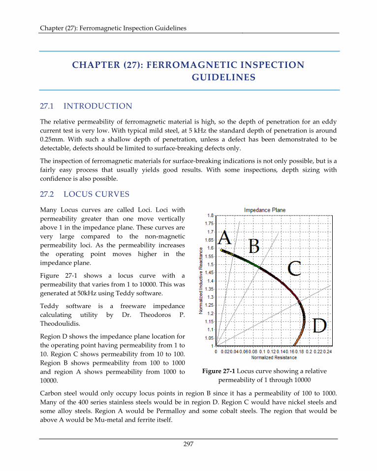
Many Locus curves are called Loci. Loci with permeability greater than one move vertically above 1 in the impedance plane. These curves are very large compared to the non-magnetic permeability loci. As the permeability increases the operating point moves higher in the impedance plane.
Figure 27-1 shows a locus curve with a permeability that varies from 1 to 10000. This was generated at 50kHz using Teddy software.
Teddy software is a freeware impedance calculating utility by Dr. Theodoros P. Theodoulidis.
Region D shows the impedance plane location for the operating point having permeability from 1 to 10. Region C shows permeability from 10 to 100. Region B shows permeability from 100 to 1000 and region A shows permeability from 1000 to 10000.
Figure 27-1 Locus curve showing a relative permeability of 1 through 10000
Carbon steel would only occupy locus points in region B since it has a permeability of 100 to 1000. Many of the 400 series stainless steels would be in region D. Region C would have nickel steels and some alloy steels. Region A would be Permalloy and some cobalt steels. The region that would be above A would be Mu-metal and ferrite itself.
Chapter (27): Ferromagnetic Inspection Guidelines
298
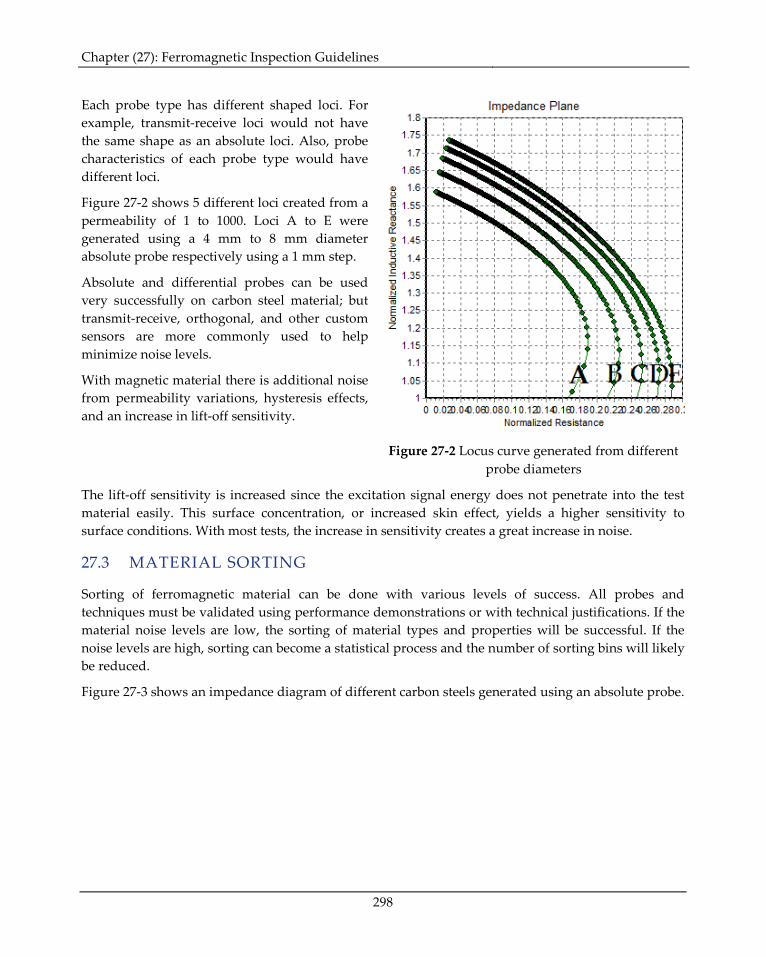
Each probe type has different shaped loci. For example, transmit-receive loci would not have the same shape as an absolute loci. Also, probe characteristics of each probe type would have different loci.
Figure 27-2 shows 5 different loci created from a permeability of 1 to 1000. Loci A to E were generated using a 4 mm to 8 mm diameter absolute probe respectively using a 1 mm step.
Absolute and differential probes can be used very successfully on carbon steel material; but transmit-receive, orthogonal, and other custom sensors are more commonly used to help minimize noise levels.
With magnetic material there is additional noise from permeability variations, hysteresis effects, and an increase in lift-off sensitivity.
Figure 27-2 Locus curve generated from different
probe diameters
The lift-off sensitivity is increased since the excitation signal energy does not penetrate into the test material easily. This surface concentration, or increased skin effect, yields a higher sensitivity to surface conditions. With most tests, the increase in sensitivity creates a great increase in noise.
27.3 MATERIAL SORTING
Sorting of ferromagnetic material can be done with various levels of success. All probes and techniques must be validated using performance demonstrations or with technical justifications. If the material noise levels are low, the sorting of material types and properties will be successful. If the noise levels are high, sorting can become a statistical process and the number of sorting bins will likely be reduced.
Figure 27-3 shows an impedance diagram of different carbon steels generated using an absolute probe.
Chapter (27): Ferromagnetic Inspection Guidelines
299
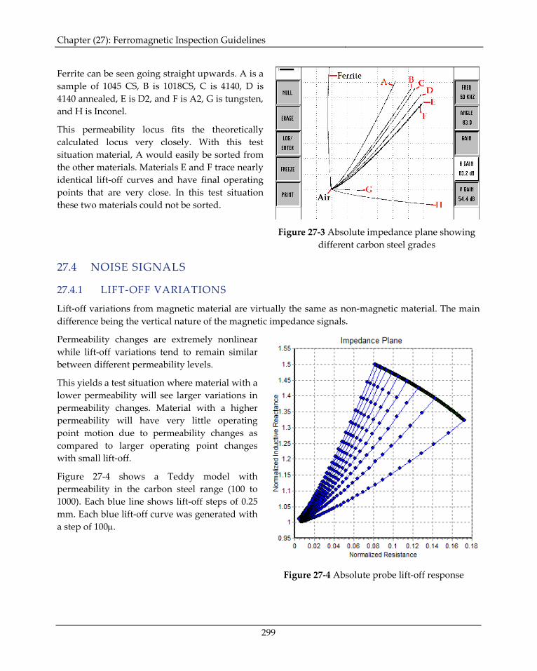
Ferrite can be seen going straight upwards. A is a sample of 1045 CS, B is 1018CS, C is 4140, D is 4140 annealed, E is D2, and F is A2, G is tungsten, and H is Inconel.
This permeability locus fits the theoretically calculated locus very closely. With this test situation material, A would easily be sorted from the other materials. Materials E and F trace nearly identical lift-off curves and have final operating points that are very close. In this test situation these two materials could not be sorted.
Figure 27-3 Absolute impedance plane showing
different carbon steel grades
27.4 NOISE SIGNALS
27.4.1 LIFT-OFF VARIATIONS
Lift-off variations from magnetic material are virtually the same as non-magnetic material. The main difference being the vertical nature of the magnetic impedance signals.
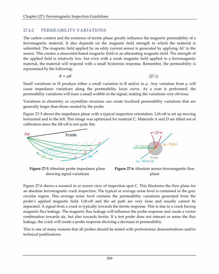
Permeability changes are extremely nonlinear while lift-off variations tend to remain similar between different permeability levels.
This yields a test situation where material with a lower permeability will see larger variations in permeability changes. Material with a higher permeability will have very little operating point motion due to permeability changes as compared to larger operating point changes with small lift-off.
Figure 27-4 shows a Teddy model with permeability in the carbon steel range (100 to 1000). Each blue line shows lift-off steps of 0.25 mm. Each blue lift-off curve was generated with a step of 100µ.
Figure 27-4 Absolute probe lift-off response
Chapter (27): Ferromagnetic Inspection Guidelines
300
27.4.2 PERMEABILITY VARIATIONS
The carbon content and the existence of ferrite phase greatly influence the magnetic permeability of a ferromagnetic material. It also depends on the magnetic field strength to which the material is submitted. The magnetic field applied by an eddy current sensor is generated by applying AC to the sensor. This creates a sinusoidal-based magnetic field or an alternating magnetic field. The strength of the applied field is relatively low, but even with a weak magnetic field applied to a ferromagnetic material, the material will respond with a small hysteresis response. Remember, the permeability is represented by the following:
𝐵 = 𝜇𝐻 (27.1)
Small variations in H produce either a small variation in B and/or in µ. Any variation from µ will cause impedance variations along the permeability locus curve. As a scan is performed, the permeability variations will trace a small wobble in the signal, making the variations very obvious.
Variations in chemistry or crystalline structure can create localized permeability variations that are generally larger than those created by the probe.
Figure 27-5 shows the impedance plane with a typical inspection orientation. Lift-off is set up moving horizontal and to the left. This image was optimized for material C. Materials A and D are tilted out of calibration since the lift-off is not quite flat.
Figure 27-5 Absolute probe impedance plane
showing signal variations Figure 27-6 Absolute sensor ferromagnetic flaw
plane
Figure 27-6 shows a zoomed in or screen view of inspection spot C. This illustrates the flaw plane for an absolute ferromagnetic crack inspection. The typical or average noise level is contained in the grey circular region. This average noise level contains the permeability variations generated from the probe’s applied magnetic field. Lift-off and the air path are very close and usually cannot be separated. A signal from a crack is typically towards the ferrite response. This is due to a crack having magnetic flux leakage. The magnetic flux leakage will influence the probe response and create a vector combination towards air, but also towards ferrite. If a test probe does not interact or sense the flux leakage, the crack will create a probe response showing a decrease in permeability.
This is one of many reasons that all probes should be tested with performance demonstrations and/or technical justifications.
Chapter (27): Ferromagnetic Inspection Guidelines
301
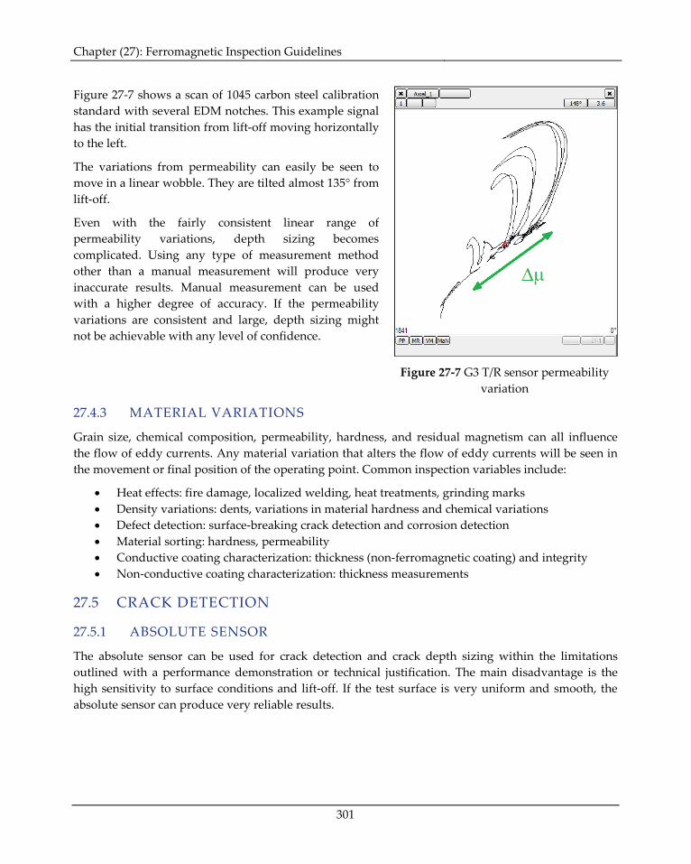
Figure 27-7 shows a scan of 1045 carbon steel calibration standard with several EDM notches. This example signal has the initial transition from lift-off moving horizontally to the left.
The variations from permeability can easily be seen to move in a linear wobble. They are tilted almost 135° from lift-off.
Even with the fairly consistent linear range of permeability variations, depth sizing becomes complicated. Using any type of measurement method other than a manual measurement will produce very inaccurate results. Manual measurement can be used with a higher degree of accuracy. If the permeability variations are consistent and large, depth sizing might not be achievable with any level of confidence.
Figure 27-7 G3 T/R sensor permeability
variation
27.4.3 MATERIAL VARIATIONS
Grain size, chemical composition, permeability, hardness, and residual magnetism can all influence the flow of eddy currents. Any material variation that alters the flow of eddy currents will be seen in the movement or final position of the operating point. Common inspection variables include:
• Heat effects: fire damage, localized welding, heat treatments, grinding marks • Density variations: dents, variations in material hardness and chemical variations • Defect detection: surface-breaking crack detection and corrosion detection • Material sorting: hardness, permeability • Conductive coating characterization: thickness (non-ferromagnetic coating) and integrity • Non-conductive coating characterization: thickness measurements
27.5 CRACK DETECTION
27.5.1 ABSOLUTE SENSOR
The absolute sensor can be used for crack detection and crack depth sizing within the limitations outlined with a performance demonstration or technical justification. The main disadvantage is the high sensitivity to surface conditions and lift-off. If the test surface is very uniform and smooth, the absolute sensor can produce very reliable results.
Chapter (27): Ferromagnetic Inspection Guidelines
302
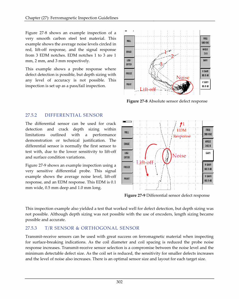
Figure 27-8 shows an example inspection of a very smooth carbon steel test material. This example shows the average noise levels circled in red, lift-off response, and the signal response from 3 EDM notches. EDM notches 1 to 3 are 1 mm, 2 mm, and 3 mm respectively.
This example shows a probe response where defect detection is possible, but depth sizing with any level of accuracy is not possible. This inspection is set up as a pass/fail inspection.
Figure 27-8 Absolute sensor defect response
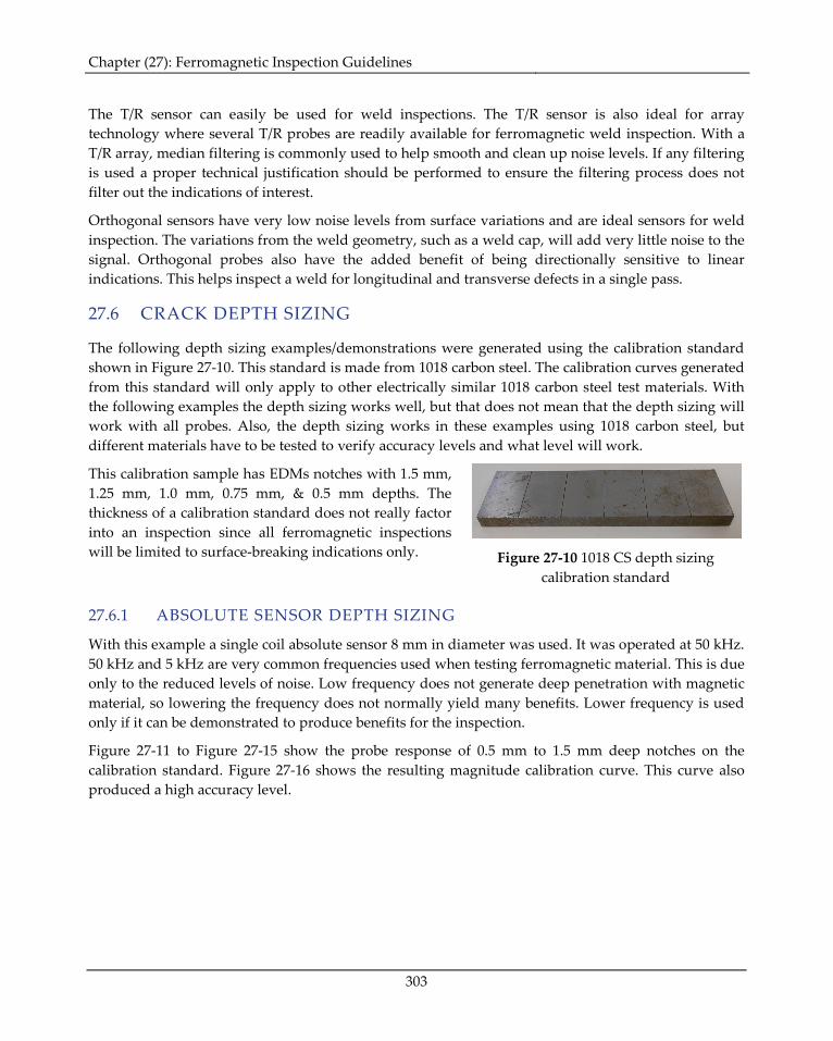
27.5.2 DIFFERENTIAL SENSOR
The differential sensor can be used for crack detection and crack depth sizing within limitations outlined with a performance demonstration or technical justification. The differential sensor is normally the first sensor to test with, due to the lower sensitivity to lift-off and surface condition variations.
Figure 27-9 shows an example inspection using a very sensitive differential probe. This signal example shows the average noise level, lift-off response, and an EDM response. This EDM is 0.1 mm wide, 0.5 mm deep and 1.0 mm long.
Figure 27-9 Differential sensor defect response
This inspection example also yielded a test that worked well for defect detection, but depth sizing was not possible. Although depth sizing was not possible with the use of encoders, length sizing became possible and accurate.
27.5.3 T/R SENSOR & ORTHOGONAL SENSOR
Transmit-receive sensors can be used with great success on ferromagnetic material when inspecting for surface-breaking indications. As the coil diameter and coil spacing is reduced the probe noise response increases. Transmit-receive sensor selection is a compromise between the noise level and the minimum detectable defect size. As the coil set is reduced, the sensitivity for smaller defects increases and the level of noise also increases. There is an optimal sensor size and layout for each target size.
Chapter (27): Ferromagnetic Inspection Guidelines
303
The T/R sensor can easily be used for weld inspections. The T/R sensor is also ideal for array technology where several T/R probes are readily available for ferromagnetic weld inspection. With a T/R array, median filtering is commonly used to help smooth and clean up noise levels. If any filtering is used a proper technical justification should be performed to ensure the filtering process does not filter out the indications of interest.
Orthogonal sensors have very low noise levels from surface variations and are ideal sensors for weld inspection. The variations from the weld geometry, such as a weld cap, will add very little noise to the signal. Orthogonal probes also have the added benefit of being directionally sensitive to linear indications. This helps inspect a weld for longitudinal and transverse defects in a single pass.
27.6 CRACK DEPTH SIZING
The following depth sizing examples/demonstrations were generated using the calibration standard shown in Figure 27-10. This standard is made from 1018 carbon steel. The calibration curves generated from this standard will only apply to other electrically similar 1018 carbon steel test materials. With the following examples the depth sizing works well, but that does not mean that the depth sizing will work with all probes. Also, the depth sizing works in these examples using 1018 carbon steel, but different materials have to be tested to verify accuracy levels and what level will work.
This calibration sample has EDMs notches with 1.5 mm, 1.25 mm, 1.0 mm, 0.75 mm, & 0.5 mm depths. The thickness of a calibration standard does not really factor into an inspection since all ferromagnetic inspections will be limited to surface-breaking indications only.
Figure 27-10 1018 CS depth sizing
calibration standard
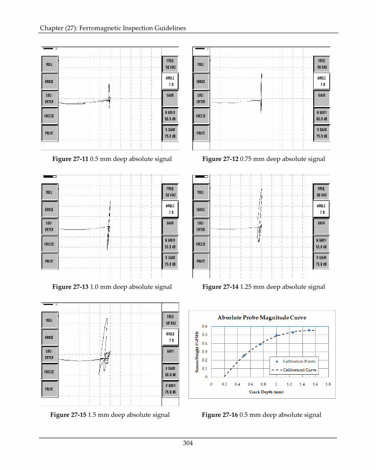
27.6.1 ABSOLUTE SENSOR DEPTH SIZING
With this example a single coil absolute sensor 8 mm in diameter was used. It was operated at 50 kHz. 50 kHz and 5 kHz are very common frequencies used when testing ferromagnetic material. This is due only to the reduced levels of noise. Low frequency does not generate deep penetration with magnetic material, so lowering the frequency does not normally yield many benefits. Lower frequency is used only if it can be demonstrated to produce benefits for the inspection.
Figure 27-11 to Figure 27-15 show the probe response of 0.5 mm to 1.5 mm deep notches on the calibration standard. Figure 27-16 shows the resulting magnitude calibration curve. This curve also produced a high accuracy level.
Chapter (27): Ferromagnetic Inspection Guidelines
304
Figure 27-11 0.5 mm deep absolute signal Figure 27-12 0.75 mm deep absolute signal
Figure 27-13 1.0 mm deep absolute signal Figure 27-14 1.25 mm deep absolute signal
Figure 27-15 1.5 mm deep absolute signal Figure 27-16 0.5 mm deep absolute signal
Chapter (27): Ferromagnetic Inspection Guidelines
305
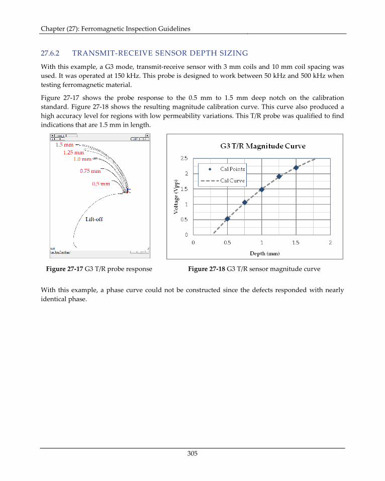
27.6.2 TRANSMIT-RECEIVE SENSOR DEPTH SIZING
With this example, a G3 mode, transmit-receive sensor with 3 mm coils and 10 mm coil spacing was used. It was operated at 150 kHz. This probe is designed to work between 50 kHz and 500 kHz when testing ferromagnetic material.
Figure 27-17 shows the probe response to the 0.5 mm to 1.5 mm deep notch on the calibration standard. Figure 27-18 shows the resulting magnitude calibration curve. This curve also produced a high accuracy level for regions with low permeability variations. This T/R probe was qualified to find indications that are 1.5 mm in length.
Figure 27-17 G3 T/R probe response Figure 27-18 G3 T/R sensor magnitude curve
With this example, a phase curve could not be constructed since the defects responded with nearly identical phase.
Chapter (27): Ferromagnetic Inspection Guidelines
306
27.6.3 ORTHOGONAL SENSOR DEPTH SIZING
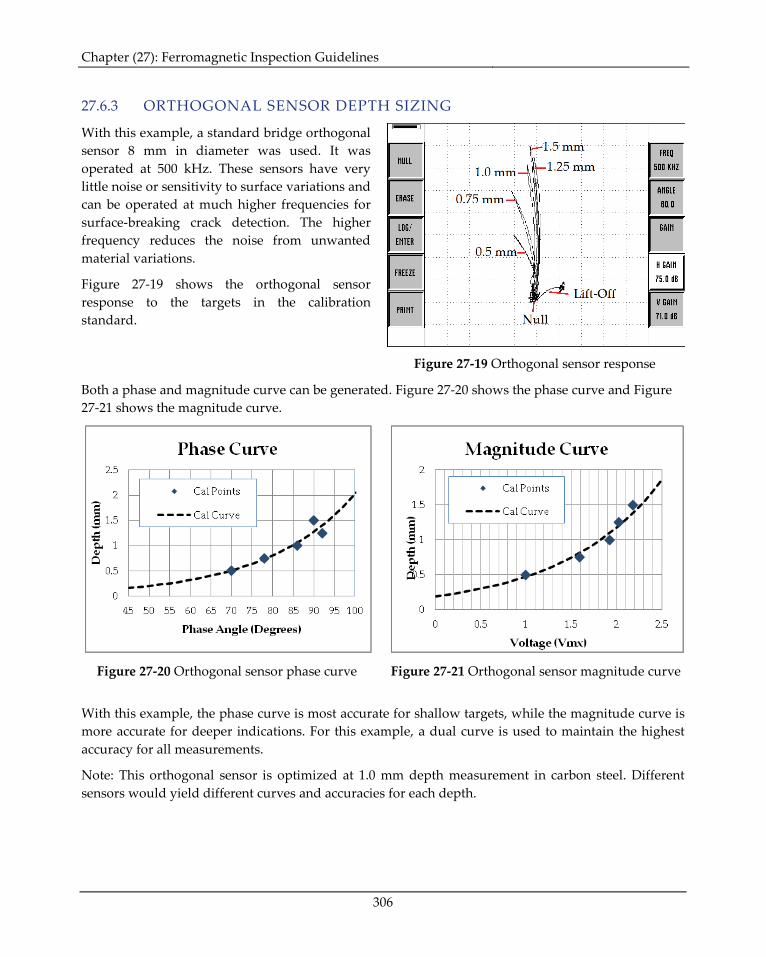
With this example, a standard bridge orthogonal sensor 8 mm in diameter was used. It was operated at 500 kHz. These sensors have very little noise or sensitivity to surface variations and can be operated at much higher frequencies for surface-breaking crack detection. The higher frequency reduces the noise from unwanted material variations.
Figure 27-19 shows the orthogonal sensor response to the targets in the calibration standard.
Figure 27-19 Orthogonal sensor response
Both a phase and magnitude curve can be generated. Figure 27-20 shows the phase curve and Figure 27-21 shows the magnitude curve.
Figure 27-20 Orthogonal sensor phase curve Figure 27-21 Orthogonal sensor magnitude curve
With this example, the phase curve is most accurate for shallow targets, while the magnitude curve is more accurate for deeper indications. For this example, a dual curve is used to maintain the highest accuracy for all measurements.
Note: This orthogonal sensor is optimized at 1.0 mm depth measurement in carbon steel. Different sensors would yield different curves and accuracies for each depth.