TABLE OF CONTENTS - Colorado State...
18
TI 101C Sampler Wiring Diagrams TABLE OF CONTENTS 1.0 PURPOSE AND APPLICABILITY ............................................................................ 2 2.1 Field Specialist ................................................................................................. 3 2.2 Technician........................................................................................................ 3 3.0 REQUIRED EQUIPMENT AND MATERIALS ......................................................... 3 4.0 METHODS ................................................................................................................. 4 4.1 Satellite Sampling Module Wiring Schematic.................................................... 4 4.2 SIM wiring schematics ..................................................................................... 6 4.3 SIM-Controller wiring schematics .................................................................... 9 4.4 Independent Controller Module Wiring Schematics .......................................... 12 TABLE OF FIGURES Figure 1 Satellite Sampling Module Wiring Schematics ................................................... 5 Figure 2 SIM1 SIM Version 1 Wiring Schematic ............................................................ 6 Figure 3 SIM1L SIM Version 1 with Lock-Out Relay Wiring Schematic ........................ 7 Figure 4 SIM2 SIM Version 2 Wiring Schematic ............................................................ 8 Figure 5 SC1 SIM Controller Module Version 1 Wiring ................................................ 9 Figure 6 SC1L SIM Controller Module Version 1 with Lock-Out Relay Wiring Schematic .................................................................................................... 10 Figure 7 Pump Delay Relay for SIM-Controller Wiring Schematic ................................ 11 Figure 8 Independent Controller Module Diagram ........................................................ 12 Figure 9 IC1 Independent Controller Version 1 Electrical Schematic ........................... 13 Figure 10 IC1L Independent Controller Version 1 with Lock-Out Relay Electrical Schematic .................................................................................................... 14 Figure 11 IC1 Independent Controller Version 1 Wiring Schematic ............................. 15 Figure 12 IC1L Independent Controller Version 1 with Lock-Out Relay Wiring Schematic .................................................................................................... 16 Figure 13 IC2 Independent Controller Version 2 Wiring Schematic .............................. 17 Figure 14 IC3 Independent Controller Version 3 Wiring Schematic .............................. 18 LIST OF TABLES Table 1 Controller Module Configurations...................................................................... 2
Transcript of TABLE OF CONTENTS - Colorado State...

TI 101C Sampler Wiring Diagrams
TABLE OF CONTENTS
1.0 PURPOSE AND APPLICABILITY............................................................................ 22.1 Field Specialist ................................................................................................. 32.2 Technician........................................................................................................ 3
3.0 REQUIRED EQUIPMENT AND MATERIALS......................................................... 34.0 METHODS................................................................................................................. 4
4.1 Satellite Sampling Module Wiring Schematic.................................................... 44.2 SIM wiring schematics ..................................................................................... 64.3 SIM-Controller wiring schematics .................................................................... 94.4 Independent Controller Module Wiring Schematics .......................................... 12
TABLE OF FIGURES
Figure 1 Satellite Sampling Module Wiring Schematics................................................... 5Figure 2 SIM1 SIM Version 1 Wiring Schematic ............................................................ 6Figure 3 SIM1L SIM Version 1 with Lock-Out Relay Wiring Schematic ........................ 7Figure 4 SIM2 SIM Version 2 Wiring Schematic ............................................................ 8Figure 5 SC1 SIM Controller Module Version 1 Wiring ................................................ 9Figure 6 SC1L SIM Controller Module Version 1 with Lock-Out Relay Wiring
Schematic .................................................................................................... 10Figure 7 Pump Delay Relay for SIM-Controller Wiring Schematic ................................ 11Figure 8 Independent Controller Module Diagram ........................................................ 12Figure 9 IC1 Independent Controller Version 1 Electrical Schematic ........................... 13Figure 10 IC1L Independent Controller Version 1 with Lock-Out Relay Electrical
Schematic .................................................................................................... 14Figure 11 IC1 Independent Controller Version 1 Wiring Schematic ............................. 15Figure 12 IC1L Independent Controller Version 1 with Lock-Out Relay Wiring
Schematic .................................................................................................... 16Figure 13 IC2 Independent Controller Version 2 Wiring Schematic .............................. 17Figure 14 IC3 Independent Controller Version 3 Wiring Schematic .............................. 18
LIST OF TABLESTable 1 Controller Module Configurations...................................................................... 2

Technical Information Document TI 101C: Sampler Wiring Diagrams 2
1.0 PURPOSE AND APPLICABILITY
This standard operating procedure (SOP) contains the current wiring schematics forIMPROVE sampling and controller modules. IMPROVE samplers are constructed at theUniversity of California at Davis by Air Quality Group personnel. There are several type ofmodules in use.
• Satellite Sampling Module: These modules require a separate signal from a controllerto start and stop sampling. There are two variations of the satellite module: PM2.5
and PM10. These are identical except the PM2.5 module has a fine inlet and a cyclone,while the PM10 module has either a Sierra or Wedding PM10 inlet.
• Independent Controller Module (IC): These non-sampling modules control multiplesatellite sampling modules. There are several versions with minor variations. Onemajor variation is the addition of a lock-out circuit to prevent a second samplecollected without an intervening sample change.
• Single Independent Module (SIM): This sampling module includes the clockcontroller in the sampling module. It cannot control satellite sampling modules.
• SIM-Controller (SC): This sampling module includes the clock controller in thesampling module, plus the relays to control satellite sampling modules. This module isnow used in place of the independent controller module.
The various configurations of the controller modules are listed in Table 1.
Table 1 Controller Module Configurations.
code pumprelay
voltage
multiplepump relay
location
pump outletlocation
thermostatand
position
lock-outdevice
IC1 24V external box in pump house noIC1L 24V external box in pump house yesIC2 110V internal box on module no
IC2L 110V internal box on module yesIC3 24V internal box on module no
IC3L 24V internal box on module yesSIM1 24V none 1 on module under noSIM2 24V none 1 on module on no
SIM2L 24V none 1 on module on yesSC1 24V external box on module on no
SC1L 24V external box on module on yes
IC Independent Controller non-sampling, controls satellite sampling modulesSIM Single Independent Module sampling, self-controlling onlySC SIM-Controller sampling, controls self and satellite sampling modules
thermostat and position: under: under the heater panel with relayson: on the heater panel

Technical Information Document TI 101C: Sampler Wiring Diagrams 3
2.0 RESPONSIBILITIES
2.1 Field SpecialistThe field specialist shall:• Maintain accurate wiring schematics for existing aerosol samplers.• Maintain records of which wiring schematic is in use at each sampling site.
2.2 TechnicianThe technician shall:• Review wiring schematics prior to maintenance or troubleshooting procedures
3.0 REQUIRED EQUIPMENT AND MATERIALSNone

Technical Information Document TI 101C: Sampler Wiring Diagrams 4
4.0 METHODSThe wiring schematics for each of the configurations in the IMPROVE network are listed in
the following sections.4.1 Satellite Sampling Module Wiring Schematic4.2 Single Independent Module (SIM) Wiring Schematics4.3 Single Independent Module (SIM) Wiring Schematics4.4 Independent Controller Module Wiring Schematics
4.1 Satellite Sampling Module Wiring SchematicAll Satellite Sampling Modules, whether PM2.5 or PM10, follow the wiring schematic of Figure
1. The procedures for attaching additional satellite Sampling modules follows.1. Install the additional Satellite Sampling module on the sampler support structure next to a
functioning Satellite Sampling module.2. Cut a length of insulated six wire cable sufficient to reach from terminal strip position 6 of
the functioning Satellite Sampling module to terminal position six of the newly installedSatellite Sampling Module.
3. Turn off the power to the sampler. For an IMPROVE controller, remove the fuse in thelower right hand side of the module.
4. Disconnect the gray six wire cable from the controller module at the terminal strip in thefunctioning Satellite Sampling Module.
5. Remove the panduit connectors, and strip the ends of the six wires in the gray cable fromthe functioning Satellite Sampling Module if necessary.
6. Strip the ends of the six wires in the new section of cable.7. Connect wires having the same color from the two cables by inserting them into a single
female panduit and crimping them in position. This connection is termed a“doublepanduit”. Check to ensure neither wire is loose.
8. Install the double panduit connections on the terminal strip, following the color code listedin Figure 1.
9. Install female panduit on the six wires at the free end of the new cable, crimping thepanduit in place firmly and checking to verify the wire will not pull out of the panduit.
10. Install the panduit on the free end of the six wire cable on the terminal strip of the newSatellite Sampling Module, following the color code listed in Figure 1.

Technical Information Document TI 101C: Sampler Wiring Diagrams 5
Figure 1 Satellite Sampling Module Wiring Schematics
to control module
WIRE IDENTIFICATION:----------------------------R = RED - filter 1 signal (24 VAC)O = ORANGE - filter 2 signal (24 VAC)G = GREEN - filter 3 signal (not used)B = BLUE - filter 4 signal (not used)Bk = BLACK - 24 VAC hotW = WHITE - 24 VAC commonY = YELLOW - 24 VAC commonGy = GREY - elapsed timers (24 VAC)
TERMINAL STRIP GUIDE:----------------------------------------------------------------pos23456789
10
1112
WIRES ON RIGHTR from cableO from cableG from cableB from cableBk from cableW from cableR from solenoid 1R from solenoid 2R from solenoid 1
R from solenoid 2
nonenone
WIRES ON LEFTR from switchO from switchnonenonenoneY from switchGy from timer 1Gy from timer 2R from switchGy from timer 1O from switchGy from timer 2nonenone
FILTER 1 FILTER 2
SWITCHSWITCH
TIMER
Y
R
R O
O
Y
8
3
12
5
101112
9
TIMER
FILTER 1 FILTER 2

Technical Information Document TI 101C: Sampler Wiring Diagrams 6
4.2 SIM wiring schematicsThe schematics for the three versions of the SIM sampler are shown in Figures 2-4.
Figure 2 SIM1 SIM Version 1 Wiring Schematic
BO
V:/OBJECTS/SKETCHES/SIMS1.SKD
W
BLK
SIM A MODULE ; S1 Wiring Diagram - 2/28/96Legend
W = White (110V common)BO = Blue Outside (24 V hot)Y = Yellow (24 V common)
CONTROLLER
BLK
10
R = Red (channel 1 switched)O = Orange (channel 2 switched)G = Green (channel 3 switched)
All solenoid wires (S) are Red
BLKG
110V Outplug forpump
W
1 2 3 4 5 6 7 8 9 CLOCK
BO R BLK WOBLK
B = Blue (channel 4 switched)GY = GreyBLK = Black (110V hot)
HEATER
Yellow insulated pair
1211 1413
G BLK
BO
R
B
OG
R
BO
W YBLK
RBO
RELAY #1BOBO R
24 VAC
W BLK
110 VACTRANSFORMER R BO
SWITCH #1
TIMER #1
YY OBO
RELAY #2BOO
YGBO
RELAY #3
O
BO
GYO
GY
W
BO
SWITCH #2
GY
TIMER #2
GY
10G
#1 #2
BLK
W
THERMOSTAT
BLK
W
Y
SOLENOID
S1
SOLENOID
S2
1211O
R
15 A
G
110V INBLK
breakerswitch
W
THERMOSTAT
FAN
BLK
B YBO
RELAY #4
OR
BO
3O S2
9B
456
87
RGYY
BO
S1
12
BLK
BLK
PUMPSWITCH
GY
W
BLKW
BY

Technical Information Document TI 101C: Sampler Wiring Diagrams 7
Figure 3 SIM1L SIM Version 1 with Lock-Out Relay Wiring Schematic
5
8
BLK
BLK
LEGENDB = BlueG = GreenO = OrangeW = WhiteBO = Blue Outside 6 wire cable
All solenoid wires (S) are Red
10 CONTROLLER
R
BLK
SIM A MODULE; S2Lwiring diagram - 2/28/96
V:/OBJECTS/SKETCHES/SIMS2L.SKD
BLKG
110V OutPlug for pump
W
1 2 3 4 5 6 7 8 9 CLOCK
BLKBO R BLK WO
B
BLK = BlackGY = GreyR = RedY = Yellow
HEATER
B
O
Y1211
110
VAC
24 V
AC
1413
B
G BLK
BO
RO
B
O
1
LATCHINGRELAY
4
A
7
R
B
R
G
+
R
BO
W YBLK
RBLK
RELAY #1BLK
24 VAC
W BLK
110 VACTRANSFORMER R BO
SWITCH #1
TIMER #1
YBLK
Y O
BLK RELAY #2
BLKG Y
BLK RELAY #3
O
GYO
GY
W
BO
SWITCH #2
GY
TIMER #2
GY
Y 10G
BLK
B
Yellow insulated pair
THERMOSTAT
Brown
B SOLENOID#1
1
BLK 3R 2
SOLENOID#2
W
3
6
O
9
+B
S1
Y
S2
1211O
R
15 A
G110V IN
breakerswitch
BLK
W
THERMOSTAT
BBLK
Y
RELAY #4BLK
OR
3O S2
9B
456
87
RGYYYBO
S1
12
BLK
BLK
PUMPSWITCH
GY
W
BLKW
FAN

Technical Information Document TI 101C: Sampler Wiring Diagrams 8
Figure 4 SIM2 SIM Version 2 Wiring Schematic
BLK
Y
BLK
LEGENDB = BlueG = GreenO = OrangeW = WhiteBO = Blue Outside 6 wire cable
All solenoid wires (S) are Red
CONTROLLER
BLK
SIM A MODULE ; S2wiring diagram - 2/28/96
V:/OBJECTS/SKETCHES/SIMS2.SKD
G
110V Outplug forpump
BLKW
1 2 3 4 5 6 7 8 9 CLOCK
BO R BLK WOBLK
BLK = BlackGY = GreyR = RedY = Yellow
HEATER
10 1211 1413
G BLK
BO
R
B
OG
R
BO
W YBLK
RBLK
RELAY #1BLK
24 VAC
W BLK
110 VACTRANSFORMER R BO
SWITCH #1
TIMER #1
YBLK
Y O
BLK RELAY #2
BLKG
BLK RELAY #3
O
GYO
GY
W
BO
SWITCH #2
GY
TIMER #2
GY
10G
BLK
Yellow insulated pair
THERMOSTAT
Brown
SOLENOID#1
1
BLK 3R 2
SOLENOID#2
W
S1 S2
1211O
R
15 A
G110V INBLK
breakerswitch
W
THERMOSTAT
BBLK
Y
RELAY #4BLK
OR
3O S2
9B
456
87
RGYY
BO
S1
12
BLK
BLK
PUMPSWITCH
GY
W
BLKW
FAN

Technical Information Document TI 101C: Sampler Wiring Diagrams 9
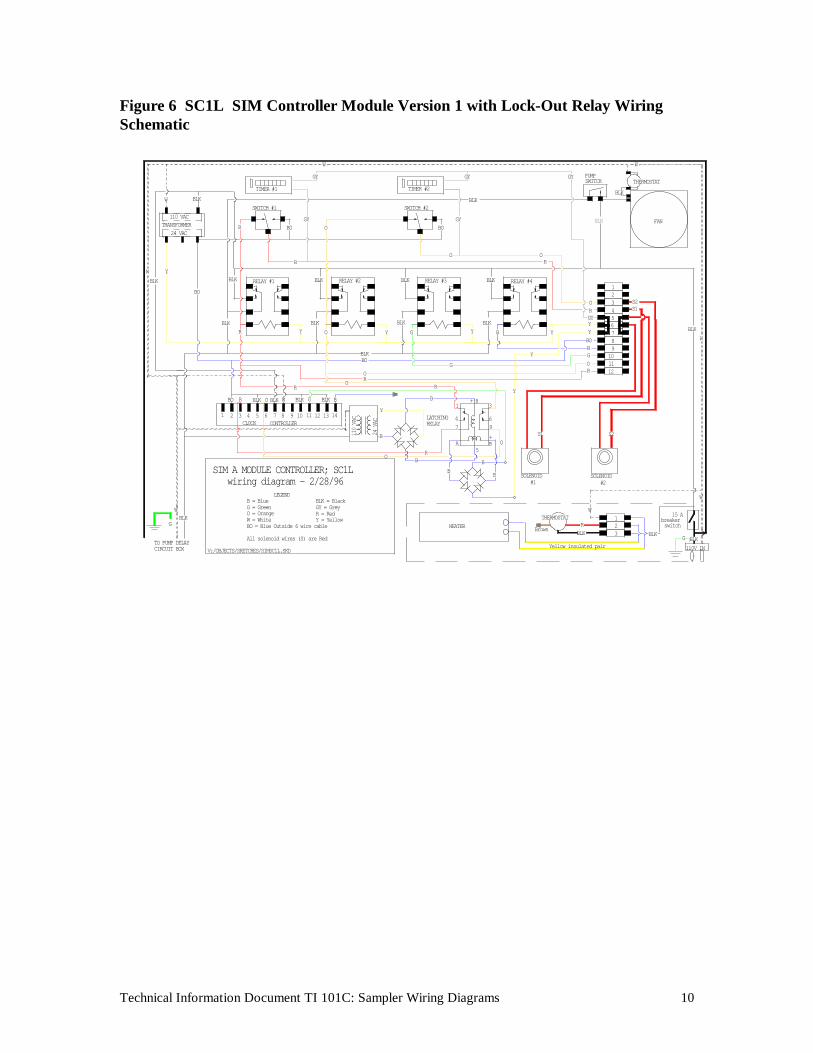
4.3 SIM-Controller wiring schematicsThe schematics for the two versions of the SIM-Controller sampler are shown in Figures 5-6.
The wiring schematic for the pump relay box is shown in Figure 7.
Figure 5 SC1 SIM Controller Module Version 1 Wiring
BLK
Y
BLK
LEGENDB = BlueG = GreenO = OrangeW = WhiteBO = Blue Outside 6 wire cable
All solenoid wires (S) are Red
CONTROLLER
BLK
SIM A MODULE CONTROLLER; SC1 wiring diagram - 2/28/96
V:/OBJECTS/SKETCHES/SIMSC1.SKD
BLK
TO PUMP DELAYCIRCUIT BOX
G
W
1 2 3 4 5 6 7 8 9 CLOCK
BO R BLK WOBLK
BLK = BlackGY = GreyR = RedY = Yellow
HEATER
10 1211 1413
G BLK
BO
R
B
OG
R
BO
W YBLK
RBLK
RELAY #1BLK
24 VAC
W BLK
110 VACTRANSFORMER R BO
SWITCH #1
TIMER #1
YBLK
Y O
BLK RELAY #2
BLKG
BLK RELAY #3
O
GYO
GY
W
BO
SWITCH #2
GY
TIMER #2
GY
10G
BLK
Yellow insulated pair
THERMOSTAT
Brown
SOLENOID#1
1
BLK 3R 2
SOLENOID#2
W
S1 S2
1211O
R
15 A
G110V INBLK
breakerswitch
W
THERMOSTAT
BBLK
Y
RELAY #4BLK
OR
3O S2
9B
456
87
RGYY
BO
S1
12
BLK
BLK
PUMPSWITCH
GY
W
BLKW
FAN
Technical Information Document TI 101C: Sampler Wiring Diagrams 10
Figure 6 SC1L SIM Controller Module Version 1 with Lock-Out Relay WiringSchematic
5
8
BLK
BLK
LEGENDB = BlueG = GreenO = OrangeW = WhiteBO = Blue Outside 6 wire cable
All solenoid wires (S) are Red
SIM A MODULE CONTROLLER; SC1L wiring diagram - 2/28/96
10 CONTROLLER
R
BLK
V:/OBJECTS/SKETCHES/SIMSC1L.SKD
BLK
TO PUMP DELAYCIRCUIT BOX
G
W
1 2 3 4 5 6 7 8 9 CLOCK
BLKBO R BLK WO
B
BLK = BlackGY = GreyR = RedY = Yellow
HEATER
B
O
Y1211
110
VAC
24 V
AC
1413
B
G BLK
BO
RO
B
O
1
LATCHINGRELAY
4
A
7
R
B
R
G
+
R
BO
W YBLK
RBLK
RELAY #1BLK
24 VAC
W BLK
110 VACTRANSFORMER R BO
SWITCH #1
TIMER #1
YBLK
Y O
BLK RELAY #2
BLKG Y
BLK RELAY #3
O
GYO
GY
W
BO
SWITCH #2
GY
TIMER #2
GY
Y 10G
BLK
B
Yellow insulated pair
THERMOSTAT
Brown
B SOLENOID#1
1
BLK 3R 2
SOLENOID#2
W
3
6
O
9+B
S1
Y
S2
1211O
R
15 A
G110V INBLK
breakerswitch
W
THERMOSTAT
BBLK
Y
RELAY #4BLK
OR
3O S2
9B
456
87
RGYYYBO
S1
12
BLK
BLK
PUMPSWITCH
GY
W
BLKW
FAN

Technical Information Document TI 101C: Sampler Wiring Diagrams 11
Figure 7 Pump Delay Relay for SIM-Controller Wiring Schematic
DECIMALS...................... +.0005ANGLES......................... +1 DEG._ PROJECT
PART NAME
SCALE
# OF PARTS
DUE DATE
CHANGE DATE
DATE
DATEDRAWN BY
CHECKED BY
APPROVED BY:
MATERIAL
DRAWING NUMBER
AIR QUALITY - IMPROVE
PUMP DELAY RELAY BOX CIRCUIT
Campbell 10/93
sheet 2 of 2C76-NPS-2403
green (C)
blue (D)
red (A)
yellow (B)
ground
24 second delay on 16 second delay on 8 second delay on
to 4
out
let b
ox
STD. TOLERANCESFRACTIONS.................... +1/64DECIMALS...................... +.005
___ CROCKER NUCLEAR LABORATORY
UNIVERSITY OF CALIFORNIA - DAVIS
16 gauge black (always hot)
white (common)
18 gauge black
RELAY D RELAY C RELAY B
to c
ontro
ller
mod
ule

Technical Information Document TI 101C: Sampler Wiring Diagrams 12
4.4 Independent Controller Module Wiring SchematicsThe six variations on the Independent Controller Module are visually similar, following the
style shown in Figure 8. Electrical schematics for the two version 1 modules are shown in Figures9-10. Wiring schematics for the various different Independent Controller Module versions followin Figures 11 through 14. Note that for all Independent Controller Modules, positions 2Athrough 2F are identical to positions 1A through 1F respectively. 1A is connected to 2A, 1B isconnected to 2B, etc.
Figure 8 Independent Controller Module Diagram
ESUF
WIRE COLOR KEYR = Red O = OrangeG = Green B = BlueBK = Black W = White
To sampling modules (slave modules)
To pumpsTo power(120 V)
NORMAL WIRING
G BK WBOR R O G B BK W
HEATERPANEL
30 MIN.
TIMER
CR8
CR9
CR10
CR11
CR12
FUSE
110V
12:00
BGOR BK W R O G B WBK
1A 1B 1C 1D 1E 1F 2A 2B 2C 2D 2E 2F 3 4 5 6 7 8 L2
1F 2A 2F1A 1B 1C 1D 1E 2B 2C 2D 2E 3 4 5 7 86 L2

Technical Information Document TI 101C: Sampler Wiring Diagrams 13
Figure 9 IC1 Independent Controller Version 1 Electrical Schematic
TC-4 CR
RED
ORANGE
GREEN
BLUE
BLACK
2-A
2-B
2-C
2-D
#57
CR-11
CR-12
CR-10TORELAYSIN PUMPHOUSE
CR-8
CR-9
9 SEC 6#56
7
3 SECTDR
6 SEC
3
4
5
#53
#54
#55
CR-12
CR-11
CR-9
CR-10TOFILTERMODULES
#3 1-C#4
2-D2-D BLACK
1-D
#2
crt.#1 1-A
1-B
PUMP
WHITE
AIR QUALITY GROUP - IMPROVE
UNIVERSITY OF CALIFORNIA-DAVIS
Controller Module Electrical Schematic
CROCKER NUCLEAR LABORATORY
D PROJEC
PART
SCAL
MATERIA
NO. OF
DUE
C
B
A
8
DRAWING
CHECKEDE.A.R.
DRAWN DAT
DAT02/29/96
C76-NPS-2362
WHITE2-FGREEN
BLUE
12
ORANGE
RED
1-F
#63
FILTERS1 & 2 OFMODULESA,B,C,&D
#58
#4
110 V POWER
24V
110V
7 DAY TIME CLOCKGRASSLIN digi 128
#68
#57
CR-830 MINBYPASS TIMER
#68
#57
SWITCH (20 F)THERMAL SWITCH (85 F)
THERMAL
L1
#58
#58
TC-2 CR
TC-3 CR11
#62
10#61
CR
TC-19CR8
#60
#59
#58
#3
#58
#2
#1
FANHEATER
RED
RED
L2

Technical Information Document TI 101C: Sampler Wiring Diagrams 14
Figure 10 IC1L Independent Controller Version 1 with Lock-Out Relay ElectricalSchematic
TC-4 CR
RED
ORANGE
GREEN
BLUE
BLACK
2-A
2-B
2-C
2-D
REMOVE
#57
CR-11
CR-12
CR-10TORELAYSIN PUMPHOUSE
CR-8
CR-9
9 SEC 6#56
7
3 SECTDR
6 SEC
3
4
5
#53
#54
#55
CR-12
CR-11
CR-9
CR-10TOFILTERMODULES
#3 1-C#4
2-D2-D BLACK
1-D
#2
crt.#1 1-A
1-B
PUMP
WHITE
AIR QUALITY GROUP - IMPROVE
UNIVERSITY OF CALIFORNIA-DAVIS
Controller Module Electrical Schematic
PROJECT
PART NAME
SCALE
MATERIAL
NO. OF PARTS
DUE DATE
DRAWING NO.
CHECKED BY
CROCKER NUCLEAR LABORATORY
E.A.R.
C76-NPS-2362A
DRAWN BY DATE
DATE02/29/96
D
C
B
A
8
WHITE2-FGREEN
BLUE
12
ORANGE
RED
1-F
#63
FILTERS1 & 2 OFMODULESA,B,C,&D
#58
#4
110 V POWER
24V
110V
REMOVE
7 DAY TIME CLOCKGRASSLIN digi 128
#68
#57
CR-8
#58#59
5
47
A B+96
+3
81 #62
30 MINBYPASS TIMER
CUT #68
#57
SWITCH (20 F)THERMAL SWITCH (85 F)
THERMAL
L1
#58
#58
TC-2 CR
#58
TC-3 CR11
#62
10#61
CR
TC-1#58
#59
9CR8
#60
#59
#58
#3
#58
#2
#1
FANHEATER
RED
RED
L2

Technical Information Document TI 101C: Sampler Wiring Diagrams 15
Figure 11 IC1 Independent Controller Version 1 Wiring Schematic
64
65
24 V Relay
58
L1
64
65
GRAY SIX WIRE CABLETO SLAVE MODULES
TO CONTACTOR BOX RELAYSIN PUMP HOUSE
Time Delay(C pump)
1A
R64
Y G B BL
1B 1C 1D 1E
65 66 67 57
66
53
67
54
54
Time Delay(B pump)
55
2D
W
2A 2B 2C1F
58 64 65 66 67
R
2E 2F 3
Y
4
57 58 53 54
55
56
56
Time Delay(D pump)
Clock Controller
61
65
53
53
68
68 60 68
TDR 3353
1 542 3
59
66
57
59
53
67CR-8
57
24 V Relay
58
68
64
62
10
L2
TDR 34
68L1
53
6 8 97
58
57
68 63
TDR 35
1411 12 13
CR-9
57
24 V Relay
60
53
6766
5757
6158
5364
58com L2
G B
85 6 7
L1 L2WBL
55 56
L2
L2
com
58
L2L1
57
57
58
L2
57
58
66
Transformer
30 Minute
Timer62
24 V
hot57
61
57
59
63
110 V
hotL1
57
58
57
62
CR-10
57
58
65
CR-11
24 V Relay
53
HEATER
FAN
THERMALSWITCH20 F
85 FSWITCH
THERMAL
24 V Relay
CR-12
57
63
53
57
58
67

Technical Information Document TI 101C: Sampler Wiring Diagrams 16
Figure 12 IC1L Independent Controller Version 1 with Lock-Out Relay WiringSchematic

Technical Information Document TI 101C: Sampler Wiring Diagrams 17
Figure 13 IC2 Independent Controller Version 2 Wiring Schematic
L2
SWITCHED POWER FOR PUMPS
69Y
4
56
GRAY SIX WIRE CABLETO SLAVE MODULES
64 65
1A
R Y
1B
66G
1C
R
G
5867 57 58 64 65 66 67 57
B BL
1D 1E 2D
W
2A 2B 2C1F 2E
R
2F 3
53
54
66
64
65
67
55
L2 L1
110 V Relay
L254
L2
B
69
L2
55
L2
L1
W Y W
W B W
GROUND
70 71 L1 L2 L2
G B W
85 6 7 L2
L2
58
58
110 V Relay
L2L1
110 V Relay
L2 56
L270
C
L1
L2
D
71
57
69
70
L1
7158
Time Delay(B pump)
TDR 33
54
53
6068
53
68
1 2 3
Time Delay(D pump)
Time Delay(C pump)
TDR 35
55 56
53 53TDR 34
12
6168 62L2 68L1
Clock Controller
54 106 8 97 11
68 63
1413
24 V Relay
65
59
64
59
L1
CR-8
53
66
67
58
57
58
57
24 V Relay
60
57
58
L1
61
L1
L1
53 64
65
68
64
CR-9
6766
53
30 Minute
HEATER
L1
69
com
110 V
hot
58com
24 V
hot57
L2
Transformer
Timer62
61
57
59
63
70
57L1
L2
THERMALSWITCH20 F
85 FSWITCH
THERMALFAN
58
58
24 V Relay
57
62
57
58
57
58
24 V Relay
L1
L1
65 53
CR-10
66
CR-11
57
58
24 V Relay
63
L1
6753
CR-12

Technical Information Document TI 101C: Sampler Wiring Diagrams 18
Figure 14 IC3 Independent Controller Version 3 Wiring Schematic
64
65
64
65
24 V Relay
24 V Relay
58
L1
R W Y W
G W B W
GROUND
SWITCHED POWER FOR PUMPSGRAY SIX WIRE CABLETO SLAVE MODULES
Time Delay(C pump)
1A
R64
Y G B BL
1B 1C 1D 1E
65 66 67 57
66
67
54
L2
L2
58
54
24 V Relay
L1
72
53
A
Time Delay(B pump)
55
55
2D
W
2A 2B 2C1F
58 64 65 66 67
R
2E 2F 3
Y
4
57 58 72 69
56
24 V Relay58
L2
L2
58
B
56
L2
L2L1
69
5854
Time Delay(D pump)
72
Clock Controller
61
65
53
53
68
68 60 68
TDR 3353
1 542 3
59
66
57
59
53
67CR-8
57
24 V Relay
58
68
64
62
10
L2
53TDR 34
68L1
6 8 97
58
57
68 63
TDR 35
1411 12 13
CR-9
57
24 V Relay
60
53
6766
5757
6158
5364
58com L2
G B W
85 6 7
70 71 L1 L2
L2
L2
58
L2
L2
58
L1
70
55
C
com
24 V Relay58
D
72
70
57
L2L1
69
72
L1
71
56
L1
L270
69
57
5871
L2
57
58
66
Transformer
30 Minute
Timer62
24 V
hot57
61
57
59
63
110 V
hotL1
57
58
57
62
CR-10
57
58
65
CR-11
24 V Relay
53
HEATER
FAN
THERMALSWITCH20 F
85 FSWITCH
THERMAL
24 V Relay
CR-12
57
63
53
57
58
67