System Manager’s Quick Reference Release 2.0 or … Manager’s Quick Reference Release 2.0 or...
175
MERLIN MAGIX™ Integrated System System Manager’s Quick Reference Release 2.0 or Earlier 555-720-119 Comcode 108873605 Issue 1 January 2001
-
Upload
truongdang -
Category
Documents
-
view
234 -
download
0
Transcript of System Manager’s Quick Reference Release 2.0 or … Manager’s Quick Reference Release 2.0 or...
MERLIN MAGIX™Integrated SystemSystem Manager’s Quick Reference
Release 2.0 or Earlier
555-720-119Comcode 108873605
Issue 1January 2001
NoticeEvery effort has been made to ensure that the information in this guide is complete and accurate at the time of printing. Information, however, is subject to change. See Appendix A, “Customer Support Information,” in Feature Reference for important information.
Avaya Web PageThe world wide web home page for Avaya is http://www.avaya.com.
Heritage StatementIntellectual property related to this product (including trademarks) and registered to Lucent Technologies Inc. has been transferred or licensed to Avaya. Any reference within the text to Lucent Technologies Inc. or Lucent should be interpreted as reference to Avaya. The exception is cross references to books published prior to April 1, 2001, which may retain their original Lucent titles. Avaya, formed as a result of Lucent's planned restructuring, designs, builds, and delivers voice, converged voice and data, customer-relationship management, messaging, multiservice networking, and structured cabling products and services. Avaya Labs is the research and development arm for the company.
Preventing Toll FraudToll Fraud is the unauthorized use of your telecommunications system by an unauthorized party (for example, a person who is not a corporate employee,agent, subcontractor, or working on your company's behalf). Be aware that there is a risk of toll fraud associated with your system and that, if toll fraud occurs, it can result in substantial additional charges for your telecommunications services.
Avaya Fraud InterventionIf you suspect that you are being victimized by toll fraud and you need technical assistance or support, call the Avaya Customer Care Center at 1 800 628-2888.
Providing Telecommunications SecurityTelecommunications security of voice, data, and/or video communications is the prevention of any type of intrusion to, that is, either unauthorized or malicious access to or use of, your company's telecommunications equipment by some party.
Your company's “telecommunications equipment” includes both this Avaya product and any other voice/data/video equipment that could be accessed via this Avaya product (that is, “networked equipment”).
An “outside party” is anyone who is not a corporate employee, agent, subcontractor, or working on your company's behalf. Whereas, a “malicious party” is anyone, including someone who may be otherwise authorized, who accesses your telecommunications equipment with either malicious or mischievous intent.
Such intrusions may be either to/through synchronous (time multiplexed and/or circuit-based) or asynchronous (character-, message-, or packet-based) equipment or interfaces for reasons of:
• Utilization (of capabilities special to the accessed equipment)• Theft (such as, of intellectual property, financial assets, or toll-facility access)• Eavesdropping (privacy invasions to humans)• Mischief (troubling, but apparently innocuous, tampering)• Harm (such as harmful tampering, data loss or alteration, regardless of motive or intent)
Copyright © 2001 Document 555-720-119
Avaya Inc. Comcode 108873605
All Rights Reserved Issue 1
Printed in USA January 2001
Be aware that there may be a risk of unauthorized or malicious intrusions associated with your system and/or its networked equipment. Also realize that, if such an intrusion should occur, it could result in a variety of losses to your company, including, but not limited to, human/data privacy, intellectual property, material assets, financial resources, labor costs, and/or legal costs.
Your Responsibility for Your Company's Telecommunications SecurityThe final responsibility for securing both this system and its networked equipment rests with you - an Avaya customer's system administrator, your telecommunications peers, and your managers. Base the fulfillment of your responsibility on acquired knowledge and resources from a variety of sources, including, but not limited to:
• Installation documents• System administration documents• Security documents• Hardware-/software-based security tools• Shared information between you and your peers• Telecommunications security experts
To prevent intrusions to your telecommunications equipment, you and your peers should carefully program and configure your:
• Avaya provided telecommunications system and their interfaces• Avaya provided software applications, as well as their underlying hardware/software platforms and interfaces• Any other equipment networked to your Avaya products
Federal Communications Commission StatementThis equipment has been tested and found to comply with the limits for a Class A digital device, pursuant to Part 15 of the FCC Rules. These limits are designed to provide reasonable protection against harmful interference when the equipment is operated in a commercial environment. This equipment generates, uses, and can radiate radio frequency energy and, if not installed and used in accordance with the instruction manual, may cause harmful interference to radio communications. Operation of this equipment in a residential area is likely to cause harmful interference, in which case the user will be required to correct the interference at their own expense. For further FCC information, see Appendix A, “Customer Support Information,” in Feature Reference.
Canadian Department of Communications (DOC) Interference InformationThis digital apparatus does not exceed the Class A limits for radio noise emissions set out in the radio interference regulations of the Canadian Department of Communications.Le Présent Appareil Numérique n’émet pas de bruits radioélectriques dépassant les limites applicables aux appareils numériques de la classe A préscrites dans le réglement sur le brouillage radioélectrique édicté par leministère des Communications du Canada.
Trademarks5ESS, AUDIX, CONVERSANT, CentreVu, DEFINITY, Magic On Hold, MERLIN, MERLIN LEGEND, MERLIN Mail, PARTNER, PassageWay, MLX-10, MLX-20L, MLX-28D, MLS-6, MLS-12, MLS-12D, MLS-18D, MLS-34D, SYSTIMAX, TransTalk, and Voice Power are registered trademarks and 4ESS, Intuity, MERLIN MAGIX, and ProLogix are trademarks of Avaya Inc. in the U.S. and other countries.Acculink, ACCUNET, MEGACOM, MulitiQuest, MLX-5, MLX-5D, MLX-16DP, MLX-10D, MLX-10DP, and NetPROTECT are registered trademarks of AT&T.Microsoft, Windows, Windows NT, and MS-DOS are registered trademarks of Microsoft Corporation.ProComm and ProComm Plus are registered trademarks of DataStorm Technologies, Inc.Supra, Supra NC, StarSet, and Mirage are registered trademarks of Plantronics, Inc.UNIX is a registered trademark of UNIX System Laboratories, Inc.PagePac is a registered trademark and Powermate and Zonemate are trademarks of DRACON, a division of Harris Corporation.Okidata is a registered trademark of Okidata Corporation.Pipeline is a trademark of Ascend Communications, Inc.Intel and Pentium are registered trademarks of Intel Corporation.Apple and Macintosh are registered trademarks of Apple Computer, Inc.IBM is a registered trademark of International Business Machines, Inc.Novell and NetWare are registered trademarks of Novell Corporation.CLASS is a servicemark of Bellcore.
Ordering Information
For more information about Avaya documents, refer to the section entitled “Related Documents” in “About This Guide” in Feature Reference.
Support Telephone NumberIn the continental U.S., Avaya provides a toll free customer helpline 24 hours a day. Call the Avaya Customer Care Center at 1 800 628-2888 or your Avaya authorized dealer if you need assistance when installing, programming, or using your system. Outside the continental U.S., contact your local Avaya authorized representative.
WarrantyAvaya provides a limited warranty on this product. Refer to “Limited Warranty and Limitation of Liability” in “Customer Support Information” in Feature Reference.
Call: Avaya Publications CenterVoice 1 800 457-1235 International Voice 317 322-6791Fax 1 800 457-1764 International Fax 317 322-6699
Write: Avaya Publications Center2855 North Franklin RoadIndianapolis, IN 46219-1385
Order: Document No. 555-720-119Comcode: 108873605Issue 1, January 2001
MERLIN MAGIX™ Integrated System Release 2.0System Manager’s Quick ReferenceSystem Information Sheet
If you have a problem with your system, you may be able to resolve it quickly and easily by following the appropriate troubleshooting procedure in this guide. If the problem persists or is not listed in this guide, call the Avaya Helpline at 1 800 628-2888 for further assistance; consultation charges may apply.
When you call the Helpline, the Avaya representatives can better help you if you have available the following system information and troubleshooting information. Also, obtain system planning Form 2a, System Numbering: Extension Jacks, and Form 2c, System Numbering: Line/Trunk Jacks.
System Information
Troubleshooting Information
Type of equipment experiencing the problem (for example, MERLIN MAGIX Integrated System, MERLIN Messaging System, or a particular system component).
Company Name (as on equipment order)Account Number (if known)Customer Identification NumberMain Listed Telephone Number (for this location)Avaya Contact Name and Telephone Number
System Information Sheet–Continued
A description of the problem:
Has this problem occurred before?
Have you attempted to troubleshoot the problem?
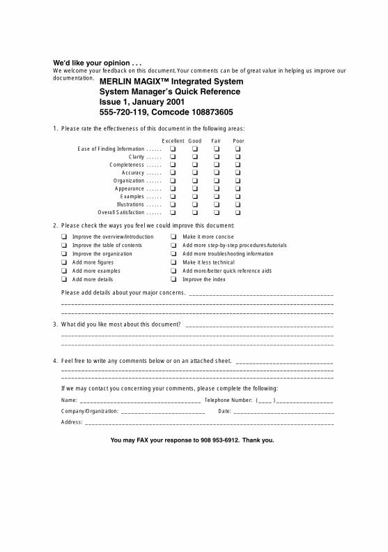
We'd like your opinion . . .We welcome your feedback on this document. Your comments can be of great value in helping us improve our documentation.
1. Please rate the effectiveness of this document in the following areas:
Excellent Good Fair Poor
Ease of Finding Information . . . . . .
Clarity . . . . . .
Completeness . . . . . .
Accuracy . . . . . .
Organization . . . . . .
Appearance . . . . . .
Examples . . . . . .
Illustrations . . . . . .
Overall Satisfaction . . . . . .
2. Please check the ways you feel we could improve this document:
Improve the overview/introduction Make it more concise
Improve the table of contents Add more step-by-step procedures/tutorials
Improve the organization Add more troubleshooting information
Add more figures Make it less technical
Add more examples Add more/better quick reference aids Add more details Improve the index
Please add details about your major concerns. ___________________________________________
_________________________________________________________________________________
_________________________________________________________________________________
3. What did you like most about this document? ____________________________________________
_________________________________________________________________________________
_________________________________________________________________________________
4. Feel free to write any comments below or on an attached sheet. _____________________________ __________________________________________________________________________________________________________________________________________________________________
If we may contact you concerning your comments, please complete the following:
Name: ____________________________________ Telephone Number: ( ____ ) _________________
Company/Organization: _________________________ Date: ______________________________
Address: __________________________________________________________________________
You may FAX your response to 908 953-6912. Thank you.
MERLIN MAGIX™ Integrated SystemSystem Manager’s Quick ReferenceIssue 1, January 2001555-720-119, Comcode 108873605

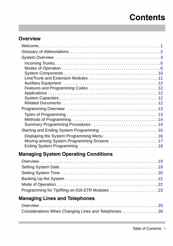
Contents
OverviewWelcome. . . . . . . . . . . . . . . . . . . . . . . . . . . . . . . . . . . . . . . . . . . . . . . . . . . . . 1Glossary of Abbreviations. . . . . . . . . . . . . . . . . . . . . . . . . . . . . . . . . . . . . . . . 2System Overview . . . . . . . . . . . . . . . . . . . . . . . . . . . . . . . . . . . . . . . . . . . . . . 3
Incoming Trunks. . . . . . . . . . . . . . . . . . . . . . . . . . . . . . . . . . . . . . . . . . . . . . 5Modes of Operation . . . . . . . . . . . . . . . . . . . . . . . . . . . . . . . . . . . . . . . . . . . 6System Components . . . . . . . . . . . . . . . . . . . . . . . . . . . . . . . . . . . . . . . . . 10Line/Trunk and Extension Modules . . . . . . . . . . . . . . . . . . . . . . . . . . . . . . 11Auxiliary Equipment . . . . . . . . . . . . . . . . . . . . . . . . . . . . . . . . . . . . . . . . . 12Features and Programming Codes . . . . . . . . . . . . . . . . . . . . . . . . . . . . . . 12Applications . . . . . . . . . . . . . . . . . . . . . . . . . . . . . . . . . . . . . . . . . . . . . . . . 12System Capacities . . . . . . . . . . . . . . . . . . . . . . . . . . . . . . . . . . . . . . . . . . . 12Related Documents . . . . . . . . . . . . . . . . . . . . . . . . . . . . . . . . . . . . . . . . . . 12
Programming Overview . . . . . . . . . . . . . . . . . . . . . . . . . . . . . . . . . . . . . . . . 13Types of Programming . . . . . . . . . . . . . . . . . . . . . . . . . . . . . . . . . . . . . . . . 13Methods of Programming. . . . . . . . . . . . . . . . . . . . . . . . . . . . . . . . . . . . . . 14Summary Programming Procedures . . . . . . . . . . . . . . . . . . . . . . . . . . . . . 14
Starting and Ending System Programming . . . . . . . . . . . . . . . . . . . . . . . . . 16Displaying the System Programming Menu . . . . . . . . . . . . . . . . . . . . . . . . 16Moving among System Programming Screens . . . . . . . . . . . . . . . . . . . . . 17Exiting System Programming . . . . . . . . . . . . . . . . . . . . . . . . . . . . . . . . . . 18
Managing System Operating ConditionsOverview. . . . . . . . . . . . . . . . . . . . . . . . . . . . . . . . . . . . . . . . . . . . . . . . . . . . 19Setting System Date . . . . . . . . . . . . . . . . . . . . . . . . . . . . . . . . . . . . . . . . . . . 19Setting System Time. . . . . . . . . . . . . . . . . . . . . . . . . . . . . . . . . . . . . . . . . . . 20Backing Up the System . . . . . . . . . . . . . . . . . . . . . . . . . . . . . . . . . . . . . . . . 21Mode of Operation . . . . . . . . . . . . . . . . . . . . . . . . . . . . . . . . . . . . . . . . . . . . 22Programming for Tip/Ring on 016 ETR Modules . . . . . . . . . . . . . . . . . . . . . 23
Managing Lines and TelephonesOverview. . . . . . . . . . . . . . . . . . . . . . . . . . . . . . . . . . . . . . . . . . . . . . . . . . . . 25Considerations When Changing Lines and Telephones . . . . . . . . . . . . . . . . 26
Table of Contents i
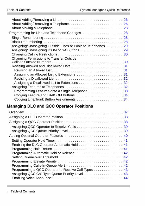
Table of Contents System Manager’s Quick Reference
About Adding/Removing a Line. . . . . . . . . . . . . . . . . . . . . . . . . . . . . . . . . 26About Adding/Removing a Telephone . . . . . . . . . . . . . . . . . . . . . . . . . . . . 26About Moving a Telephone . . . . . . . . . . . . . . . . . . . . . . . . . . . . . . . . . . . . 28
Programming for Line and Telephone Changes . . . . . . . . . . . . . . . . . . . . . 28Single Renumbering . . . . . . . . . . . . . . . . . . . . . . . . . . . . . . . . . . . . . . . . . 28Block Renumbering . . . . . . . . . . . . . . . . . . . . . . . . . . . . . . . . . . . . . . . . . . 28Assigning/Unassigning Outside Lines or Pools to Telephones . . . . . . . . . 29Assigning/Unassigning ICOM or SA Buttons . . . . . . . . . . . . . . . . . . . . . . 29Changing Calling Restrictions . . . . . . . . . . . . . . . . . . . . . . . . . . . . . . . . . . 30Changing Permissions to Transfer OutsideCalls to Outside Numbers . . . . . . . . . . . . . . . . . . . . . . . . . . . . . . . . . . . . . 30Revising Allowed and Disallowed Lists . . . . . . . . . . . . . . . . . . . . . . . . . . . 31
Revising an Allowed List . . . . . . . . . . . . . . . . . . . . . . . . . . . . . . . . . . . . . 31Assigning an Allowed List to Extensions . . . . . . . . . . . . . . . . . . . . . . . . 31Revising a Disallowed List . . . . . . . . . . . . . . . . . . . . . . . . . . . . . . . . . . . 32Assigning a Disallowed List to Extensions . . . . . . . . . . . . . . . . . . . . . . . 32
Assigning Features to Telephones . . . . . . . . . . . . . . . . . . . . . . . . . . . . . . 32Programming Features onto a Single Telephone . . . . . . . . . . . . . . . . . . 33Copying Feature and SA/ICOM Buttons. . . . . . . . . . . . . . . . . . . . . . . . . 34Copying Line/Trunk Button Assignments . . . . . . . . . . . . . . . . . . . . . . . . 34
Managing DLC and QCC Operator PositionsOverview . . . . . . . . . . . . . . . . . . . . . . . . . . . . . . . . . . . . . . . . . . . . . . . . . . . 37Assigning a DLC Operator Position . . . . . . . . . . . . . . . . . . . . . . . . . . . . . . . 38Assigning a QCC Operator Position. . . . . . . . . . . . . . . . . . . . . . . . . . . . . . . 38
Assigning QCC Operator to Receive Calls . . . . . . . . . . . . . . . . . . . . . . . . 39Assigning QCC Queue Priority Level . . . . . . . . . . . . . . . . . . . . . . . . . . . . 39
Adding Optional Operator Features . . . . . . . . . . . . . . . . . . . . . . . . . . . . . . . 40Setting Operator Hold Timer . . . . . . . . . . . . . . . . . . . . . . . . . . . . . . . . . . 41Enabling the DLC Operator Automatic Hold . . . . . . . . . . . . . . . . . . . . . . . 41Programming Hold Return . . . . . . . . . . . . . . . . . . . . . . . . . . . . . . . . . . . . 41Programming Automatic Hold or Release . . . . . . . . . . . . . . . . . . . . . . . . . 42Setting Queue over Threshold . . . . . . . . . . . . . . . . . . . . . . . . . . . . . . . . . 42Programming Elevate Priority . . . . . . . . . . . . . . . . . . . . . . . . . . . . . . . . . . 42Programming Calls-In-Queue Alert . . . . . . . . . . . . . . . . . . . . . . . . . . . . . . 42Programming a QCC Operator to Receive Call Types . . . . . . . . . . . . . . . 43Assigning QCC Call Type Queue Priority Level . . . . . . . . . . . . . . . . . . . . 43Enabling Voice Announce . . . . . . . . . . . . . . . . . . . . . . . . . . . . . . . . . . . . . 44
ii Table of Contents
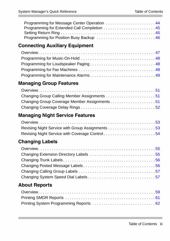
Table of ContentsSystem Manager’s Quick Reference
Programming for Message Center Operation . . . . . . . . . . . . . . . . . . . . . . 44Programming for Extended Call Completion . . . . . . . . . . . . . . . . . . . . . . . 45Setting Return Ring . . . . . . . . . . . . . . . . . . . . . . . . . . . . . . . . . . . . . . . . . . 45Programming for Position Busy Backup . . . . . . . . . . . . . . . . . . . . . . . . . . 46
Connecting Auxiliary EquipmentOverview. . . . . . . . . . . . . . . . . . . . . . . . . . . . . . . . . . . . . . . . . . . . . . . . . . . . 47Programming for Music-On-Hold . . . . . . . . . . . . . . . . . . . . . . . . . . . . . . . . . 48Programming for Loudspeaker Paging . . . . . . . . . . . . . . . . . . . . . . . . . . . . . 48Programming for Fax Machines . . . . . . . . . . . . . . . . . . . . . . . . . . . . . . . . . . 49Programming for Maintenance Alarms . . . . . . . . . . . . . . . . . . . . . . . . . . . . . 49
Managing Group FeaturesOverview. . . . . . . . . . . . . . . . . . . . . . . . . . . . . . . . . . . . . . . . . . . . . . . . . . . . 51Changing Group Calling Member Assignments . . . . . . . . . . . . . . . . . . . . . . 51Changing Group Coverage Member Assignments . . . . . . . . . . . . . . . . . . . . 51Changing Coverage Delay Rings . . . . . . . . . . . . . . . . . . . . . . . . . . . . . . . . . 52
Managing Night Service FeaturesOverview. . . . . . . . . . . . . . . . . . . . . . . . . . . . . . . . . . . . . . . . . . . . . . . . . . . . 53Revising Night Service with Group Assignments . . . . . . . . . . . . . . . . . . . . . 53Revising Night Service with Coverage Control . . . . . . . . . . . . . . . . . . . . . . . 54
Changing LabelsOverview. . . . . . . . . . . . . . . . . . . . . . . . . . . . . . . . . . . . . . . . . . . . . . . . . . . . 55Changing Extension Directory Labels . . . . . . . . . . . . . . . . . . . . . . . . . . . . . 55Changing Trunk Labels . . . . . . . . . . . . . . . . . . . . . . . . . . . . . . . . . . . . . . . . . 56Changing Posted Message Labels . . . . . . . . . . . . . . . . . . . . . . . . . . . . . . . . 56Changing Calling Group Labels . . . . . . . . . . . . . . . . . . . . . . . . . . . . . . . . . . 57Changing System Speed Dial Labels . . . . . . . . . . . . . . . . . . . . . . . . . . . . . . 57
About ReportsOverview. . . . . . . . . . . . . . . . . . . . . . . . . . . . . . . . . . . . . . . . . . . . . . . . . . . . 59Printing SMDR Reports . . . . . . . . . . . . . . . . . . . . . . . . . . . . . . . . . . . . . . . . 61Printing System Programming Reports . . . . . . . . . . . . . . . . . . . . . . . . . . . . 62
Table of Contents iii
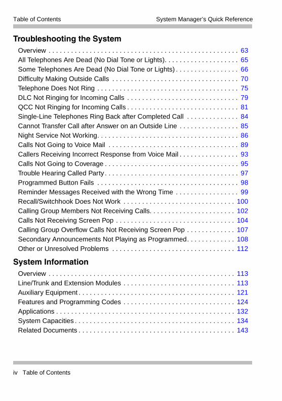
Table of Contents System Manager’s Quick Reference
Troubleshooting the SystemOverview . . . . . . . . . . . . . . . . . . . . . . . . . . . . . . . . . . . . . . . . . . . . . . . . . . . 63All Telephones Are Dead (No Dial Tone or Lights). . . . . . . . . . . . . . . . . . . . 65Some Telephones Are Dead (No Dial Tone or Lights) . . . . . . . . . . . . . . . . . 66Difficulty Making Outside Calls . . . . . . . . . . . . . . . . . . . . . . . . . . . . . . . . . . 70Telephone Does Not Ring . . . . . . . . . . . . . . . . . . . . . . . . . . . . . . . . . . . . . . 75DLC Not Ringing for Incoming Calls . . . . . . . . . . . . . . . . . . . . . . . . . . . . . . 79QCC Not Ringing for Incoming Calls . . . . . . . . . . . . . . . . . . . . . . . . . . . . . . 81Single-Line Telephones Ring Back after Completed Call . . . . . . . . . . . . . . 84Cannot Transfer Call after Answer on an Outside Line . . . . . . . . . . . . . . . . 85Night Service Not Working. . . . . . . . . . . . . . . . . . . . . . . . . . . . . . . . . . . . . . 86Calls Not Going to Voice Mail . . . . . . . . . . . . . . . . . . . . . . . . . . . . . . . . . . . 89Callers Receiving Incorrect Response from Voice Mail . . . . . . . . . . . . . . . . 93Calls Not Going to Coverage . . . . . . . . . . . . . . . . . . . . . . . . . . . . . . . . . . . . 95Trouble Hearing Called Party . . . . . . . . . . . . . . . . . . . . . . . . . . . . . . . . . . . . 97Programmed Button Fails . . . . . . . . . . . . . . . . . . . . . . . . . . . . . . . . . . . . . . 98Reminder Messages Received with the Wrong Time . . . . . . . . . . . . . . . . . 99Recall/Switchhook Does Not Work . . . . . . . . . . . . . . . . . . . . . . . . . . . . . . 100Calling Group Members Not Receiving Calls. . . . . . . . . . . . . . . . . . . . . . . 102Calls Not Receiving Screen Pop . . . . . . . . . . . . . . . . . . . . . . . . . . . . . . . . 104Calling Group Overflow Calls Not Receiving Screen Pop . . . . . . . . . . . . . 107Secondary Announcements Not Playing as Programmed. . . . . . . . . . . . . 108Other or Unresolved Problems . . . . . . . . . . . . . . . . . . . . . . . . . . . . . . . . . 112
System InformationOverview . . . . . . . . . . . . . . . . . . . . . . . . . . . . . . . . . . . . . . . . . . . . . . . . . . 113Line/Trunk and Extension Modules . . . . . . . . . . . . . . . . . . . . . . . . . . . . . . 113Auxiliary Equipment . . . . . . . . . . . . . . . . . . . . . . . . . . . . . . . . . . . . . . . . . . 121Features and Programming Codes . . . . . . . . . . . . . . . . . . . . . . . . . . . . . . 124Applications . . . . . . . . . . . . . . . . . . . . . . . . . . . . . . . . . . . . . . . . . . . . . . . . 132System Capacities . . . . . . . . . . . . . . . . . . . . . . . . . . . . . . . . . . . . . . . . . . . 134Related Documents . . . . . . . . . . . . . . . . . . . . . . . . . . . . . . . . . . . . . . . . . . 143
iv Table of Contents
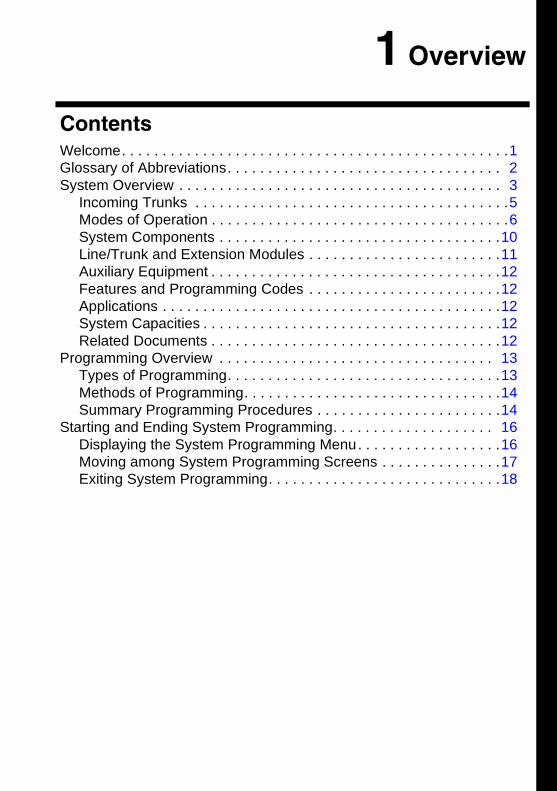
1 Overview
Contents
Welcome. . . . . . . . . . . . . . . . . . . . . . . . . . . . . . . . . . . . . . . . . . . . . . . .1Glossary of Abbreviations. . . . . . . . . . . . . . . . . . . . . . . . . . . . . . . . . . 2System Overview . . . . . . . . . . . . . . . . . . . . . . . . . . . . . . . . . . . . . . . . 3Incoming Trunks . . . . . . . . . . . . . . . . . . . . . . . . . . . . . . . . . . . . . . .5Modes of Operation . . . . . . . . . . . . . . . . . . . . . . . . . . . . . . . . . . . . .6System Components . . . . . . . . . . . . . . . . . . . . . . . . . . . . . . . . . . .10Line/Trunk and Extension Modules . . . . . . . . . . . . . . . . . . . . . . . .11Auxiliary Equipment . . . . . . . . . . . . . . . . . . . . . . . . . . . . . . . . . . . .12Features and Programming Codes . . . . . . . . . . . . . . . . . . . . . . . .12Applications . . . . . . . . . . . . . . . . . . . . . . . . . . . . . . . . . . . . . . . . . .12System Capacities . . . . . . . . . . . . . . . . . . . . . . . . . . . . . . . . . . . . .12Related Documents . . . . . . . . . . . . . . . . . . . . . . . . . . . . . . . . . . . .12
Programming Overview . . . . . . . . . . . . . . . . . . . . . . . . . . . . . . . . . . 13Types of Programming. . . . . . . . . . . . . . . . . . . . . . . . . . . . . . . . . .13Methods of Programming. . . . . . . . . . . . . . . . . . . . . . . . . . . . . . . .14Summary Programming Procedures . . . . . . . . . . . . . . . . . . . . . . .14
Starting and Ending System Programming. . . . . . . . . . . . . . . . . . . . 16Displaying the System Programming Menu. . . . . . . . . . . . . . . . . .16Moving among System Programming Screens . . . . . . . . . . . . . . .17Exiting System Programming. . . . . . . . . . . . . . . . . . . . . . . . . . . . .18
1 Overview
WelcomeThis quick reference is designed to help you administer the MERLIN MAGIX� Integrated System. It provides summary programming procedures for everyday tasks you perform in order to manage your system.
This chapter provides a system overview that describes the major aspects of the system, a programming overview that explains the types of programming available for the system, and a description of the methods available to implement the programming. Procedures to start and end system programming are also provided in this chapter.
The remaining chapters in the quick reference are organized into categories designed to help you locate a task you need to perform. For example, if you need to add a telephone, you would look for the procedure in Chapter 3, “Managing Lines and Telephones.” If you need to make a change to the system that involves an operator’s console, you would look for the procedure in Chapter 4, “Managing DLC and QCC Operator Positions.” You would typically refer to this quick reference whenever you need to perform a few programming tasks, such as assigning a new operator position, and then programming features for the operator’s telephone. You should use the Table of Contents to locate the desired task.
Prior to using this quick reference, you should become familiar with the Feature Reference, which provides detailed programming procedures and descriptions of all features used with the system.
Welcome 1
1 Overview System Manager’s Quick Reference
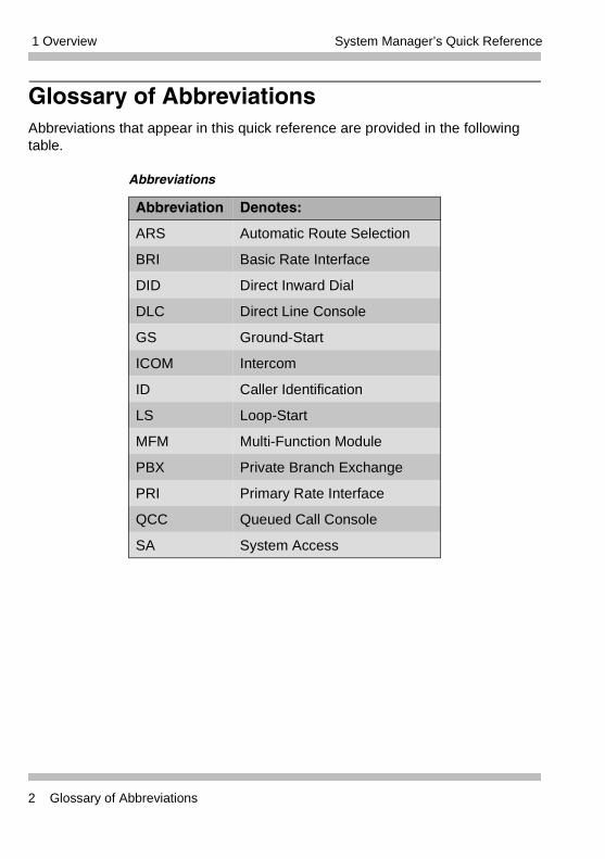
Glossary of AbbreviationsAbbreviations that appear in this quick reference are provided in the following table.
Abbreviations
Abbreviation Denotes:
ARS Automatic Route Selection
BRI Basic Rate Interface
DID Direct Inward Dial
DLC Direct Line Console
GS Ground-Start
ICOM Intercom
ID Caller Identification
LS Loop-Start
MFM Multi-Function Module
PBX Private Branch Exchange
PRI Primary Rate Interface
QCC Queued Call Console
SA System Access
2 Glossary of Abbreviations
1 OverviewSystem Manager’s Quick Reference
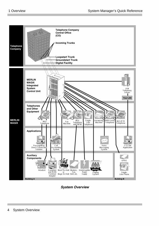
System OverviewThe MERLIN MAGIX Integrated System is a switch located on a company’s premises, which provides access to powerful features and advanced telephone network applications and services.The system can handle voice and data calls simultaneously, and voice features can enhance the use of data communications. The system accommodates businesses with needs ranging from only a few telephones to as many as 200 telephones. Its modular design allows for easy expansion. The following figure illustrates a MERLIN MAGIX system connected to telephones, applications, and auxiliary equipment.
System Overview 3
1 Overview System Manager’s Quick Reference
System Overview
TelephoneCompany
MERLINMAGIX
FaxMachine
AnsweringMachine
Telephonesand OtherEquipment
4400-SeriesTelephone
Single-Line
Telephone
MLXTelephonewith MFM
MERLINMAGIXIntegratedSystemControl Unit
Telephone CompanyCentral Office(CO)
Incoming Trunks
Applications
LANTelephony
Server
MLXTelephone
Your LAN
MLS/ETRTelephone
VoiceMessaging
System
CallAccounting
System
CTI LinkApplication
PassageWayDirect Connection
Solution
AuxiliaryComponents
Music-On-Holdor
Magic On Hold
Modem, Fax,
Bell, etc.PagingSystem
UninterruptiblePowerSupply
Computerand ISDNTerminalAdapter
Building B
HOLD
“Attention”
Single-Line Phone
OPRE
Building A
Data
EXPRESSROUTEDigital Adapter 1000
Headset
Loopstart TrunkGroundstart TrunkDigital Facility
4 System Overview
1 OverviewSystem Manager’s Quick Reference
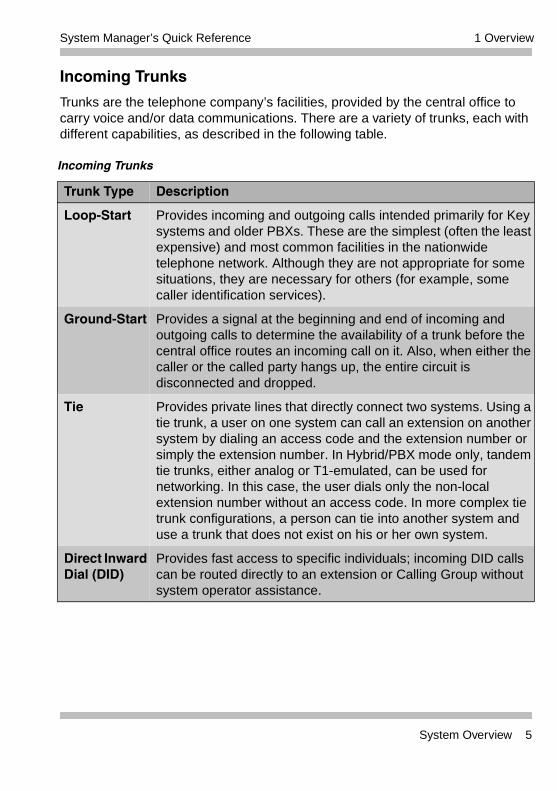
Incoming Trunks
Trunks are the telephone company’s facilities, provided by the central office to carry voice and/or data communications. There are a variety of trunks, each with different capabilities, as described in the following table.
Incoming Trunks
Trunk Type Description
Loop-Start Provides incoming and outgoing calls intended primarily for Key systems and older PBXs. These are the simplest (often the least expensive) and most common facilities in the nationwide telephone network. Although they are not appropriate for some situations, they are necessary for others (for example, some caller identification services).
Ground-Start Provides a signal at the beginning and end of incoming and outgoing calls to determine the availability of a trunk before the central office routes an incoming call on it. Also, when either the caller or the called party hangs up, the entire circuit is disconnected and dropped.
Tie Provides private lines that directly connect two systems. Using a tie trunk, a user on one system can call an extension on another system by dialing an access code and the extension number or simply the extension number. In Hybrid/PBX mode only, tandem tie trunks, either analog or T1-emulated, can be used for networking. In this case, the user dials only the non-local extension number without an access code. In more complex tie trunk configurations, a person can tie into another system and use a trunk that does not exist on his or her own system.
Direct Inward Dial (DID)
Provides fast access to specific individuals; incoming DID calls can be routed directly to an extension or Calling Group without system operator assistance.
System Overview 5
1 Overview System Manager’s Quick Reference
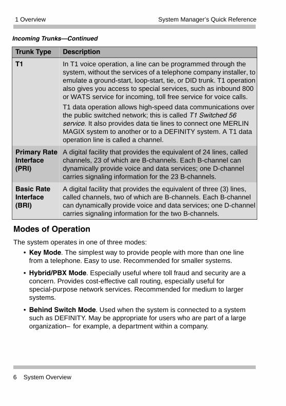
Modes of Operation
The system operates in one of three modes:
• Key Mode. The simplest way to provide people with more than one line from a telephone. Easy to use. Recommended for smaller systems.
• Hybrid/PBX Mode. Especially useful where toll fraud and security are a concern. Provides cost-effective call routing, especially useful for special-purpose network services. Recommended for medium to larger systems.
• Behind Switch Mode. Used when the system is connected to a system such as DEFINITY. May be appropriate for users who are part of a large organization–for example, a department within a company.
T1 In T1 voice operation, a line can be programmed through the system, without the services of a telephone company installer, to emulate a ground-start, loop-start, tie, or DID trunk. T1 operation also gives you access to special services, such as inbound 800 or WATS service for incoming, toll free service for voice calls.
T1 data operation allows high-speed data communications over the public switched network; this is called T1 Switched 56 service. It also provides data tie lines to connect one MERLIN MAGIX system to another or to a DEFINITY system. A T1 data operation line is called a channel.
Primary Rate Interface (PRI)
A digital facility that provides the equivalent of 24 lines, called channels, 23 of which are B-channels. Each B-channel can dynamically provide voice and data services; one D-channel carries signaling information for the 23 B-channels.
Basic Rate Interface (BRI)
A digital facility that provides the equivalent of three (3) lines, called channels, two of which are B-channels. Each B-channel can dynamically provide voice and data services; one D-channel carries signaling information for the two B-channels.
Incoming Trunks–Continued
Trunk Type Description
6 System Overview
1 OverviewSystem Manager’s Quick Reference
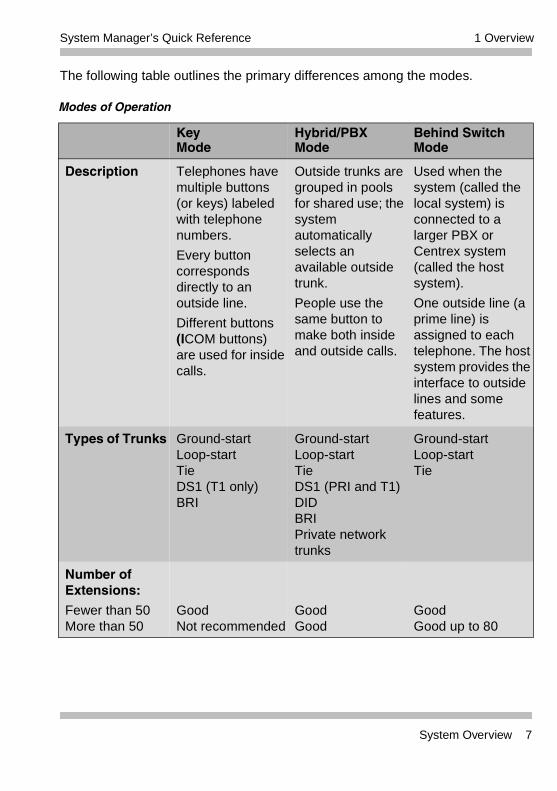
The following table outlines the primary differences among the modes.
Modes of Operation
KeyMode
Hybrid/PBX Mode
Behind Switch Mode
Description Telephones have multiple buttons (or keys) labeled with telephone numbers.
Every button corresponds directly to an outside line.
Different buttons (ICOM buttons) are used for inside calls.
Outside trunks are grouped in pools for shared use; the system automatically selects an available outside trunk.
People use the same button to make both inside and outside calls.
Used when the system (called the local system) is connected to a larger PBX or Centrex system (called the host system).
One outside line (a prime line) is assigned to each telephone. The host system provides the interface to outside lines and some features.
Types of Trunks Ground-startLoop-startTieDS1 (T1 only)BRI
Ground-startLoop-startTieDS1 (PRI and T1)DIDBRIPrivate network trunks
Ground-startLoop-startTie
Number of Extensions:
Fewer than 50More than 50
GoodNot recommended
GoodGood
GoodGood up to 80
System Overview 7
1 Overview System Manager’s Quick Reference
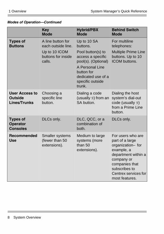
Types of Buttons
A line button for each outside line.
Up to 10 ICOM buttons for inside calls.
Up to 10 SA buttons.
Pool button(s) to access a specific pool(s). (Optional)
A Personal Line button for dedicated use of a specific outside trunk.
For multiline telephones:
Multiple Prime Line buttons. Up to 10 ICOM buttons.
User Access to Outside Lines/Trunks
Choosing a specific line button.
Dialing a code (usually 9) from an SA button.
Dialing the host system’s dial-out code (usually 9) from a Prime Line button.
Types of Operator Consoles
DLCs only. DLC, QCC, or a combination of both.
DLCs only.
Recommended Use
Smaller systems (fewer than 50 extensions).
Medium to large systems (more than 50 extensions).
For users who are part of a large organization–for example, a department within a company or companies that subscribes to Centrex services for most features.
Modes of Operation–Continued
KeyMode
Hybrid/PBX Mode
Behind Switch Mode
8 System Overview
1 OverviewSystem Manager’s Quick Reference
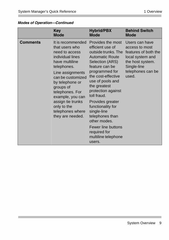
Comments It is recommended that users who need to access individual lines have multiline telephones.
Line assignments can be customized by telephone or groups of telephones. For example, you can assign tie trunks only to the telephones where they are needed.
Provides the most efficient use of outside trunks. The Automatic Route Selection (ARS) feature can be programmed for the cost-effective use of pools and the greatest protection against toll fraud.
Provides greater functionality for single-line telephones than other modes.
Fewer line buttons required for multiline telephone users.
Users can have access to most features of both the local system and the host system. Single-line telephones can be used.
Modes of Operation–Continued
KeyMode
Hybrid/PBX Mode
Behind Switch Mode
System Overview 9
1 Overview System Manager’s Quick Reference
System Components
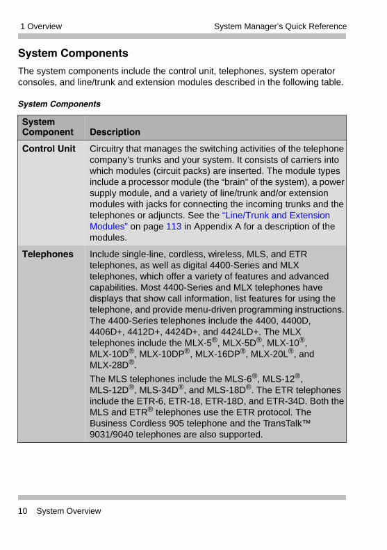
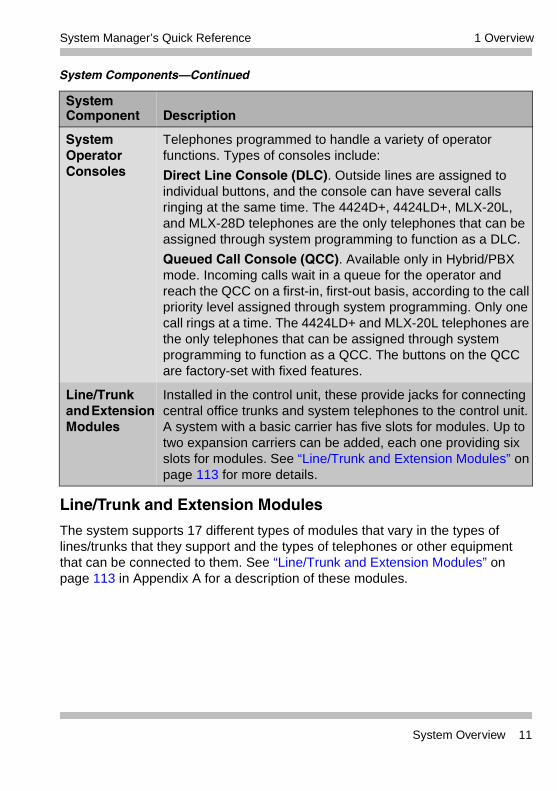
The system components include the control unit, telephones, system operator consoles, and line/trunk and extension modules described in the following table.
System Components
System Component Description
Control Unit Circuitry that manages the switching activities of the telephone company’s trunks and your system. It consists of carriers into which modules (circuit packs) are inserted. The module types include a processor module (the “brain” of the system), a power supply module, and a variety of line/trunk and/or extension modules with jacks for connecting the incoming trunks and the telephones or adjuncts. See the “Line/Trunk and Extension Modules” on page 113 in Appendix A for a description of the modules.
Telephones Include single-line, cordless, wireless, MLS, and ETR telephones, as well as digital 4400-Series and MLX telephones, which offer a variety of features and advanced capabilities. Most 4400-Series and MLX telephones have displays that show call information, list features for using the telephone, and provide menu-driven programming instructions. The 4400-Series telephones include the 4400, 4400D, 4406D+, 4412D+, 4424D+, and 4424LD+. The MLX telephones include the MLX-5®, MLX-5D®, MLX-10®, MLX-10D®, MLX-10DP®, MLX-16DP®, MLX-20L®, and MLX-28D®.
The MLS telephones include the MLS-6®, MLS-12®, MLS-12D®, MLS-34D®, and MLS-18D®. The ETR telephones include the ETR-6, ETR-18, ETR-18D, and ETR-34D. Both the MLS and ETR® telephones use the ETR protocol. The Business Cordless 905 telephone and the TransTalk™ 9031/9040 telephones are also supported.
10 System Overview
1 OverviewSystem Manager’s Quick Reference
Line/Trunk and Extension Modules
The system supports 17 different types of modules that vary in the types of lines/trunks that they support and the types of telephones or other equipment that can be connected to them. See “Line/Trunk and Extension Modules” on page 113 in Appendix A for a description of these modules.
System Operator Consoles
Telephones programmed to handle a variety of operator functions. Types of consoles include:
Direct Line Console (DLC). Outside lines are assigned to individual buttons, and the console can have several calls ringing at the same time. The 4424D+, 4424LD+, MLX-20L, and MLX-28D telephones are the only telephones that can be assigned through system programming to function as a DLC.
Queued Call Console (QCC). Available only in Hybrid/PBX mode. Incoming calls wait in a queue for the operator and reach the QCC on a first-in, first-out basis, according to the call priority level assigned through system programming. Only one call rings at a time. The 4424LD+ and MLX-20L telephones are the only telephones that can be assigned through system programming to function as a QCC. The buttons on the QCC are factory-set with fixed features.
Line/Trunk and Extension Modules
Installed in the control unit, these provide jacks for connecting central office trunks and system telephones to the control unit. A system with a basic carrier has five slots for modules. Up to two expansion carriers can be added, each one providing six slots for modules. See “Line/Trunk and Extension Modules” on page 113 for more details.
System Components–Continued
System Component Description
System Overview 11
1 Overview System Manager’s Quick Reference
Auxiliary Equipment
The system supports a variety of auxiliary equipment such as alerts, fax machines, and telephone headsets. See “Auxiliary Equipment” on page 121 in Appendix A for a list of available equipment.
Features and Programming Codes
The versatility and power of the system are due, in large part, to the variety of feature settings and services it can provide. The system provides traditional features, such as Transfer and Call Waiting, as well as advanced features, such as Coverage and Park. Through system programming, you can program features onto user’s telephones; through extension programming, individual users can change their extension features to meet individual needs. See “Features and Programming Codes” on page 124 in Appendix A for a list of features and programming codes.
Applications
Numerous add-on products, called applications, are available to enhance the system. Appendix K, “Applications,” in the Feature Reference provides a description of all available applications. See “Applications” on page 132 in Appendix A for a brief description of some of these applications.
System Capacities
See “System Capacities” on page 134 in Appendix A for a list of hardware and software capacities of the system.
Related Documents
See “Related Documents” on page 143 in Appendix A for a complete list of documents included in the MERLIN MAGIX documentation set. To order a document within the continental United States, contact the Avaya Publications Center by calling 1 800 457-1235.
12 System Overview
1 OverviewSystem Manager’s Quick Reference
Programming OverviewThe MERLIN MAGIX Integrated System offers easy-to-use, menu-driven software for system programming. As part of the installation, your system was programmed with features, settings, and options selected by you or a representative from your company. The system programming software allows you to easily modify the system programming to accommodate your company’s changing needs for such enhancements and modifications as upgraded lines, additional modules, and new extension programming.
There are three types of programming, as well as two ways, or methods, to perform the programming. The types of programming and methods of programming are described in the following sections.
Types of Programming
Three types of programming are available for the MERLIN MAGIX system:
• System Programming. This type of programming enables the System Manager to program features that affect all or most system users; it requires one of the following:
– A system programming console which is an MLX-20L or 4424LD+ telephone connected to one of the first five jacks of the first MLX or TDL module in the control unit. For more information about the system programming console, see “Programming” in the Feature Reference.
– A PC with Windows System Programming and Maintenance (WinSPM). WinSPM provides two interfaces for system programming–Quick Access and Standard SPM Mode. Quick Access provides a graphical user interface (GUI) for those tasks most commonly performed by the System Manager (for example, adding or deleting members of groups, performing system inventories, creating reports, administering multiple systems, making station labels shown on display telephones, and more). Pictorial representations of system components, such as modules and their vintages, and the creation of MLX or 4400-Series telephone button labels are available with WinSPM.
The Standard SPM Mode provides an emulation display of the system programming console. It allows basic SPM programming of the
Programming Overview 13

1 Overview System Manager’s Quick Reference
MERLIN MAGIX system and supports SPM programming for options not included in the GUI.
WinSPM is supported in Windows 95, Windows NT, and Windows 98 and is available on CD-ROM and floppy disks. WinSPM software can be used directly from the floppy disks or CD-ROM on your PC. If your PC has a hard disk, however, you should install WinSPM from either the floppy disks or CD-ROM onto the hard disk.
• Extension Programming. This type of programming enables individual extension users and system operators (except for Queued Call Console operators) to change their extension features to meet individual needs. For details about extension programming, see the appropriate user and operator guides.
• Centralized Telephone Programming. This type of programming enables the System Manager to program any feature that can be programmed by individual extension users or system operators. Some features can be programmed only in centralized telephone programming. Centralized telephone programming can be done on the programming console or through WinSPM.
Methods of Programming
As System Manager, you primarily perform system programming and centralized telephone programming. As previously explained, the other type of programming–extension programming–is performed at each individual telephone, usually by the telephone user.
To perform system programming and centralized telephone programming, the following two methods are available:
• Programming from the system programming console.
• Programming from a PC with WinSPM software.
Summary Programming Procedures
This quick reference provides summary programming procedures for both the system programming console and a PC with WinSPM using the Standard SPM Mode. The Standard SPM Mode provides an emulation display of the system programming console. Summary programming procedures for the most common system management tasks are provided.
14 Programming Overview
1 OverviewSystem Manager’s Quick Reference
You should become familiar with the detailed information about programming procedures provided in “Programming” in the Feature Reference before you use the summary programming procedures provided in this quick reference.
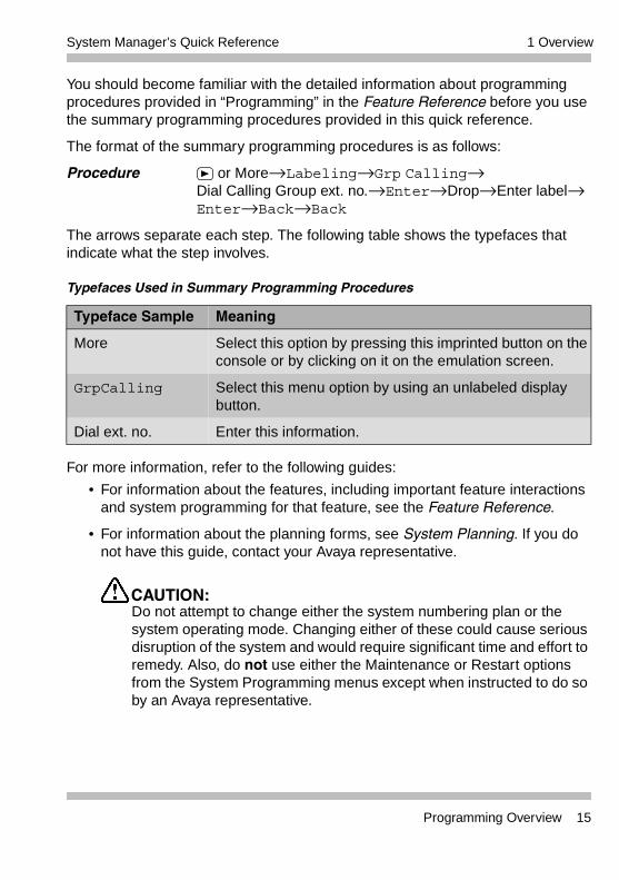
The format of the summary programming procedures is as follows:
Procedure or More→Labeling→Grp Calling→Dial Calling Group ext. no.→Enter→Drop→Enter label→ Enter→Back→Back
The arrows separate each step. The following table shows the typefaces that indicate what the step involves.
For more information, refer to the following guides:
• For information about the features, including important feature interactions and system programming for that feature, see the Feature Reference.
• For information about the planning forms, see System Planning. If you do not have this guide, contact your Avaya representative.
CAUTION:Do not attempt to change either the system numbering plan or the system operating mode. Changing either of these could cause serious disruption of the system and would require significant time and effort to remedy. Also, do not use either the Maintenance or Restart options from the System Programming menus except when instructed to do so by an Avaya representative.
Typefaces Used in Summary Programming Procedures
Typeface Sample Meaning
More Select this option by pressing this imprinted button on the console or by clicking on it on the emulation screen.
GrpCalling Select this menu option by using an unlabeled display button.
Dial ext. no. Enter this information.
Programming Overview 15
1 Overview System Manager’s Quick Reference
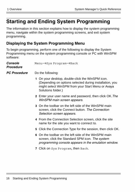
Starting and Ending System ProgrammingThe information in this section explains how to display the system programming menu, navigate within the system programming screens, and exit system programming.
Displaying the System Programming Menu
To begin programming, perform one of the following to display the System Programming menu on the system programming console or PC with WinSPM software:
Console Procedure
Menu→Sys Program→Back
PC Procedure Do the following:
1 On your desktop, double-click the WinSPM icon. (Depending on options selected during installation, you might select WinSPM from your Start Menu or Avaya Solutions folder.)
2 Enter your user name and password, then click OK.The WinSPM main screen appears.
3 On the toolbar on the left side of the WinSPM main screen, click the Connect button. The Connection Selection screen appears.
4 From the Connection Selection screen, click the site name for the site you want to connect to.
5 Click the Connection Type for the session, then click OK.
6 On the toolbar on the left side of the WinSPM main screen, click the Standard SPM icon. The system programming console appears in the emulation window.
7 Click on Sys Program, then Back.
16 Starting and Ending System Programming
1 OverviewSystem Manager’s Quick Reference
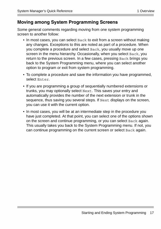
Moving among System Programming Screens
Some general comments regarding moving from one system programming screen to another follow:
• In most cases, you can select Back to exit from a screen without making any changes. Exceptions to this are noted as part of a procedure. When you complete a procedure and select Back, you usually move up one screen in the menu hierarchy. Occasionally, when you select Back, you return to the previous screen. In a few cases, pressing Back brings you back to the System Programming menu, where you can select another option to program or exit from system programming.
• To complete a procedure and save the information you have programmed, select Enter.
• If you are programming a group of sequentially numbered extensions or trunks, you may optionally select Next. This saves your entry and automatically provides the number of the next extension or trunk in the sequence, thus saving you several steps. If Next displays on the screen, you can use it with the current option.
• In most cases, you will be at an intermediate step in the procedure you have just completed. At that point, you can select one of the options shown on the screen and continue programming, or you can select Back again. This usually takes you back to the System Programming menu. If not, you can continue programming on the current screen or select Back again.
Starting and Ending System Programming 17
1 Overview System Manager’s Quick Reference
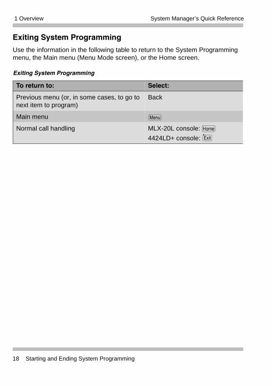
Exiting System Programming
Use the information in the following table to return to the System Programming menu, the Main menu (Menu Mode screen), or the Home screen.
Exiting System Programming
To return to: Select:
Previous menu (or, in some cases, to go to next item to program)
Back
Main menu
Normal call handling MLX-20L console: h
4424LD+ console:
Menu
Exit
18 Starting and Ending System Programming
2 Managing System OperatingConditions
Contents
Overview. . . . . . . . . . . . . . . . . . . . . . . . . . . . . . . . . . . . . . . . . . . . . . .19Setting System Date . . . . . . . . . . . . . . . . . . . . . . . . . . . . . . . . . . . . . .19Setting System Time. . . . . . . . . . . . . . . . . . . . . . . . . . . . . . . . . . . . . .20Backing Up the System . . . . . . . . . . . . . . . . . . . . . . . . . . . . . . . . . . 21Mode of Operation . . . . . . . . . . . . . . . . . . . . . . . . . . . . . . . . . . . . . . 22Programming for Tip/Ring on 016 ETR Modules . . . . . . . . . . . . . . . 23
2 Managing System OperatingConditions
OverviewThis chapter provides procedures that are related to system-wide operation, rather than to the operation of individual telephones, operator positions, lines, or trunks. It includes procedures to set the system time and date, and back up the system.
There may be occasions when you need to program ports on a 016 ETR module as T/R ports. The procedure to perform this task is also provided in this chapter.
Setting System DateUse this procedure to change the System Date. This feature allows you to set the month, day, and year that appear on display telephones and on Station Message Detail Recording (SMDR) reports.
The System Date must be set correctly. System Date affects the functioning of several system features and applications, including Automatic Backup, Night Service, SMDR reports, stand-alone Auto Attendant systems, Voice Mail, and Reminder Service.
Procedure System→Date→Drop→Dial current date→Enter→ Back
Overview 19
2 Managing System Operating Conditions System Manager’s Quick Reference
Setting System TimeUse this procedure to change the System Time. This feature allows you to set the time that appears on display telephones and on SMDR reports.
The System Time must be set correctly. System Time affects the functioning of several system features and applications, including Automatic Backup, Night Service, SMDR reports, stand-alone Auto Attendant systems, Voice Mail, and Reminder Service.
Procedure System→Time→Drop→Dial current time→ Enter→Back
In Release 1.5 and later systems, if the Automatic Daylight Savings Time feature is not active, be sure to change the system time appropriately when Daylight Savings Time starts and when it ends. In Release 1.0 systems, you must change the system time manually.
20 Setting System Time
2 Managing System Operating ConditionsSystem Manager’s Quick Reference
Backing Up the SystemUse this procedure to make a copy of your customized system data. The backup does not copy any application data. For information about application backup, see the documentation for the application.
Procedure Insert memory card→System→Back/Restore→ Backup→Select backup file→Dial new backup filename (1 to 11 characters)→Enter→Yes→Back→Back→Back
• By default, the system is set to perform a backup automatically once a week. You can change this to daily backups or to manual backups. For more information, see Installation, SPM, Maintenance, and Troubleshooting.
• If any type of programming is taking place at another extension when you begin the backup procedure, the backup is cancelled and the number of the first busy extension appears on the screen. Attempt the backup procedure again when the busy extension becomes idle.
Backing Up the System 21
2 Managing System Operating Conditions System Manager’s Quick Reference
Mode of OperationThe system mode–Key, Behind Switch, or Hybrid/PBX–determines how the system operates and directly affects the following operations:
• How lines and/or trunks are provided to users
• Types of operator consoles allowed
• Features available
Changing this option causes a system restart and terminates the programming session. You must enter system programming again to program other features.
The following options cannot be programmed for Behind Switch or Key systems:
• Automatic Route Selection (ARS)
• Pools
• Queued Call Consoles (QCCs) and associated features
• Direct Inward Dialing (DID) Trunks
• System Access buttons
• Dial Plan Routing (PRI)
• Call-by-Call Services (PRI)
The Ground-Start lines/trunks option cannot be programmed if the processor module has been modified for Permanent Key mode operation only.
Procedure System→Mode→Select mode (Key, Behind Switch, or Hybrid/PBX)→Enter
The Hybrid/PBX option is not available if the control unit processor module has been modified to operate in Permanent Key mode only. See the Feature Reference for more information.
22 Mode of Operation
2 Managing System Operating ConditionsSystem Manager’s Quick Reference
Programming for Tip/Ring on 016 ETR ModulesUse this procedure to program ports 11 through 16 on a 016 ETR module as T/R ports.
When a port on a 016 ETR module is changed from ETR to T/R or from T/R to ETR, all programming assigned to the extension (such as inclusion in coverage groups and Calling Groups) is cleared and the extension is restored to the functionality defined with the factory settings (such as Calling Restrictions and button assignments).
Procedure Extensions→ or More→ or More→ETR→Type ext. no.→ Enter→Select port type (ETR or Tip Ring)→Enter→ Back→Back
A system forced idle occurs when you perform this task. In addition to assigning either T/R or ETR functionality, with this task you are also able to determine whether a port on a 016 ETR module has been administered as T/R or ETR. However, because this task forces the entire system into a forced idle state, it is recommended you do not use it to determine how the port has been administered. Instead, to determine the functionality of an ETR port, you should do one of the following:
• Print an Extensions Print report. The report shows:
– “T/R” if the port is programmed as T/R.
– “ETR” if the port is programmed as ETR and an MLS or ETR telephone is connected to the port.
– “UNEQUIPPED” if the port is programmed as ETR and an MLS or ETR telephone is not connected to the port.
• View the extension profile by using this procedure: Maintenance→Port→Station→StatusThe profile shows the same information as previously listed for the Extensions Print report.
Programming for Tip/Ring on 016 ETR Modules 23
2 Managing System Operating Conditions System Manager’s Quick Reference
24 Programming for Tip/Ring on 016 ETR Modules
3 Managing Lines and Telephones
Contents
Overview. . . . . . . . . . . . . . . . . . . . . . . . . . . . . . . . . . . . . . . . . . . . . . .25Considerations When Changing Lines and Telephones. . . . . . . . . . 26About Adding/Removing a Line . . . . . . . . . . . . . . . . . . . . . . . . . . .26About Adding/Removing a Telephone . . . . . . . . . . . . . . . . . . . . . .26About Moving a Telephone . . . . . . . . . . . . . . . . . . . . . . . . . . . . . .28
Programming for Line and Telephone Changes. . . . . . . . . . . . . . . . .28Single Renumbering . . . . . . . . . . . . . . . . . . . . . . . . . . . . . . . . . . .28Block Renumbering . . . . . . . . . . . . . . . . . . . . . . . . . . . . . . . . . . . .28Assigning/Unassigning Outside Lines or Pools to Telephones . . .29Assigning/Unassigning ICOM or SA Buttons . . . . . . . . . . . . . . . . .29Changing Calling Restrictions . . . . . . . . . . . . . . . . . . . . . . . . . . . .30Changing Permissions to Transfer OutsideCalls to Outside Numbers . . . . . . . . . . . . . . . . . . . . . . . . . . . . . . .30Revising Allowed and Disallowed Lists . . . . . . . . . . . . . . . . . . . . .31
Revising an Allowed List . . . . . . . . . . . . . . . . . . . . . . . . . . . . .31Assigning an Allowed List to Extensions . . . . . . . . . . . . . . . . .31Revising a Disallowed List . . . . . . . . . . . . . . . . . . . . . . . . . . . .32Assigning a Disallowed List to Extensions . . . . . . . . . . . . . . . .32
Assigning Features to Telephones . . . . . . . . . . . . . . . . . . . . . . . .32Programming Features onto a Single Telephone . . . . . . . . . . .33Copying Feature and SA/ICOM Buttons . . . . . . . . . . . . . . . . .34Copying Line/Trunk Button Assignments . . . . . . . . . . . . . . . . .34
3 Managing Lines and Telephones
OverviewThis chapter provides procedures that are related to the operation of telephones, lines, and trunks. It provides a review of things you need to consider when you change lines and telephones. This chapter also provides procedures to add, remove, and move lines or telephones; assign ICOM and SA buttons to telephones, change calling restrictions for telephones; and assign features to buttons on telephones.
Overview 25
3 Managing Lines and Telephones System Manager’s Quick Reference
Considerations When Changing Lines and TelephonesBefore you add, remove, or move a line or telephone, review the information provided in the following three sections–“About Adding/Removing a Line,” “About Adding/Removing a Telephone,” and “About Moving a Telephone.”
About Adding/Removing a Line
You must contact your central office to obtain a new line or to disconnect a line. If you are adding a line, after the central office is contacted, call Avaya at 1 800 247-7000 to arrange for an Avaya technician to connect the line to the system and set it up (charges may apply).
Assign the line to or unassign the line from a pool, to/from extensions (if it is a Personal Line), to/from a Calling Group, or to/from Remote Access, as appropriate.
About Adding/Removing a Telephone
When you add or remove a telephone, you must first understand system numbering. In addition, when adding a telephone, you must make decisions about which features and buttons to assign to the telephone; when removing a telephone, you must remove all features that were programmed for that telephone. Also, when removing a telephone, you must remove it from any groups and lists to which it is assigned (for example, Allowed Lists, Calling Restrictions, Coverage, Calling Group, Pickup Group, Paging Group, and/or Night Service).
See “System Renumbering” in the Feature Reference for detailed information about system numbering and the planning required to add or remove a telephone.
If you are adding a line but there is no spare jack, you also need to add a new module. Contact your Avaya representative. After the line is connected and set up, or after it is disconnected, you must program it.
26 Considerations When Changing Lines and Telephones
3 Managing Lines and TelephonesSystem Manager’s Quick Reference
• If your system uses the Set Up Space numbering plan (see Form 2a in System Planning) and you want to add or remove a single telephone, see “Single Renumbering” on page 28.
• If your system uses the Set Up Space numbering plan (see Form 2a in System Planning) and you want to add or remove a group of telephones, see “Block Renumbering” on page 28.
• If you are adding or removing a Personal Line, Loudspeaker Paging, or Pool buttons, see “Assigning/Unassigning Outside Lines or Pools to Telephones” on page 29.
• If you are adding a telephone and you want to copy line/trunk button assignments, pool dial-out Code Restrictions (Hybrid/PBX only), and Night Service information (for operator positions only), see “Copying Line/Trunk Button Assignments” on page 34.
• If you want to assign or unassign ICOM or SA buttons, see “Assigning/Unassigning ICOM or SA Buttons” on page 29.
• On the MLS-12 and MLS-12D telephones, some features and lines may be assigned to telephone buttons that do not have lights. You may want to reassign the features or lines to buttons with lights. To do this, see “Assigning/Unassigning ICOM or SA Buttons” on page 29.
• The system software cannot distinguish between ETR-6 and MLS-6 telephones; it sees the two telephones as the same type of telephone. The default button assignments, however, are different. You should change the MLS-6 button assignments to the ETR-6 assignments to reduce confusion. To do this, see “Assigning/Unassigning ICOM or SA Buttons” on page 29.
• If you need to program a 016 ETR module for tip/ring functionality, see “Programming for Tip/Ring on 016 ETR Modules” on page 23.
• If you are adding a Business Cordless 905 telephone, a TransTalk 9040 or a TransTalk 9031 telephone connected through an ETR module, the system assigns the same buttons as those assigned for an MLS-12D telephone. The system also assigns these buttons for a TransTalk 9040 telephone connected to a TDL port.
• To program or remove any additional features to the extension, see the corresponding feature in the Feature Reference.
Considerations When Changing Lines and Telephones 27
3 Managing Lines and Telephones System Manager’s Quick Reference
About Moving a Telephone
When you move a telephone, you must renumber the extension jack for the telephone. Renumbering changes the extension number, but the programming of the telephone stays the same. To renumber a telephone or group of telephones, see “Single Renumbering” and “Block Renumbering” in the following sections.
Programming for Line and Telephone ChangesThe programming tasks provided in the following sections are all relevant to changing lines and telephones in your system. Based on the considerations provided at the beginning of this chapter, perform the necessary tasks.
Single Renumbering
If your system uses the Set Up Space numbering plan and you want to add, remove, or move a single telephone, use this procedure to single-renumber the extension jack.
Procedure SysRenumber→Single→Select item→Dial old ext. no.→Enter→Dial new ext. no.→Enter→Back→Back
Block Renumbering
If your system uses the Set Up Space numbering plan and you want to add, remove, or move a group of telephones, use this procedure to renumber the group of extension jacks. Both the original numbers and the numbers to which they are being changed must be sequential.
A system forced idle occurs when you perform this task.
A system forced idle occurs when you perform this task.
28 Programming for Line and Telephone Changes
3 Managing Lines and TelephonesSystem Manager’s Quick Reference
Procedure SysRenumber→Block→Select type of group→Dial no. of first group member→Enter→Dial no. of last group member→ Enter→Dial new beginning no.→Enter→Back→Back→ Back
Assigning/Unassigning Outside Lines or Pools to Telephones
If you are adding or removing a Personal Line, Loudspeaker Paging, or Pool buttons (Hybrid/PBX only), use this procedure to assign or unassign the outside lines/trunks to the buttons on the telephone.
Procedure To program a single line/trunk:
Extensions→Lines/Trunks→Dial ext. no.→Enter→ Entry Mode→Dial line/trunk no.→Enter→Back→Back
To program a block of lines/trunks:
Extensions→Lines/Trunks→Dial ext. no.→Enter→ Select trunk range→Toggle LED On/Off→Enter→Back→Back
Assigning/Unassigning ICOM or SA Buttons
Use this procedure to assign or unassign the Intercom (ICOM) buttons used to make and receive inside calls. In Hybrid/PBX mode only, use this procedure to assign or unassign System Access (SA) buttons used to make and receive inside and outside calls.
Procedure To program an extension:
Sys Programming→ or More→Cntr-Prg→Program Ext→Dial ext. no.→Enter→Start→Select button→Dial feature code (*16 or *18)→Enter→(Repeat from beginning to program another button)→Back→Back
To copy extension programming:
Sys Programming→ or More→Cntr-Prg→Copy ext→Dial copy from ext. no.→Enter→Dial copy to ext. no.→Enter→Back→Back
Programming for Line and Telephone Changes 29
3 Managing Lines and Telephones System Manager’s Quick Reference
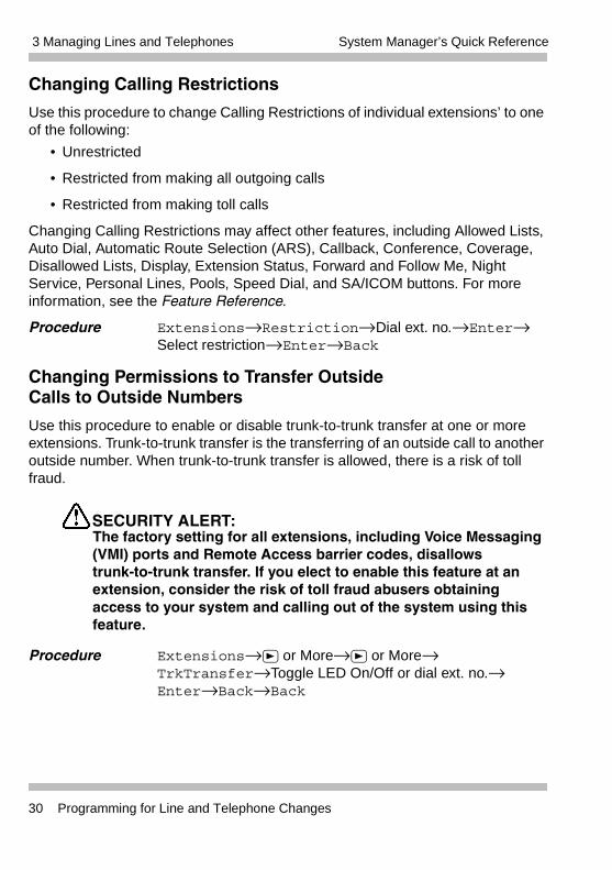
Changing Calling Restrictions
Use this procedure to change Calling Restrictions of individual extensions’ to one of the following:
• Unrestricted
• Restricted from making all outgoing calls
• Restricted from making toll calls
Changing Calling Restrictions may affect other features, including Allowed Lists, Auto Dial, Automatic Route Selection (ARS), Callback, Conference, Coverage, Disallowed Lists, Display, Extension Status, Forward and Follow Me, Night Service, Personal Lines, Pools, Speed Dial, and SA/ICOM buttons. For more information, see the Feature Reference.
Procedure Extensions→Restriction→Dial ext. no.→Enter→ Select restriction→Enter→Back
Changing Permissions to Transfer OutsideCalls to Outside Numbers
Use this procedure to enable or disable trunk-to-trunk transfer at one or more extensions. Trunk-to-trunk transfer is the transferring of an outside call to another outside number. When trunk-to-trunk transfer is allowed, there is a risk of toll fraud.
SECURITY ALERT:The factory setting for all extensions, including Voice Messaging (VMI) ports and Remote Access barrier codes, disallows trunk-to-trunk transfer. If you elect to enable this feature at an extension, consider the risk of toll fraud abusers obtaining access to your system and calling out of the system using this feature.
Procedure Extensions→ or More→ or More→TrkTransfer→Toggle LED On/Off or dial ext. no.→Enter→Back→Back
30 Programming for Line and Telephone Changes
3 Managing Lines and TelephonesSystem Manager’s Quick Reference
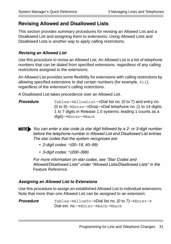
Revising Allowed and Disallowed Lists
This section provides summary procedures for revising an Allowed List and a Disallowed List and assigning them to extensions. Using Allowed Lists and Disallowed Lists is another way to apply calling restrictions.
Revising an Allowed List
Use this procedure to revise an Allowed List. An Allowed List is a list of telephone numbers that can be dialed from specified extensions, regardless of any calling restrictions assigned to the extensions.
An Allowed List provides some flexibility for extensions with calling restrictions by allowing specified extensions to dial certain numbers (for example, 911), regardless of the extension’s calling restrictions.
A Disallowed List takes precedence over an Allowed List.
Procedure Tables→AllowList→Dial list no. (0 to 7) and entry no. (0 to 9)→Enter→Drop→Dial telephone no. (1 to 14 digits; 1 to 7 digits in Release 1.0 systems; leading 1 counts as a digit)→Enter→Back
Assigning an Allowed List to Extensions
Use this procedure to assign an established Allowed List to individual extensions. Note that more than one Allowed List can be assigned to an extension.
Procedure Tables→AllowTo→Dial list no. (0 to 7)→Enter→Dial ext. no.→Enter→Back→Back
You can enter a star code (a star digit followed by a 2- or 3-digit number before the telephone number in Allowed List and Disallowed List entries. The star codes that the system recognizes are:
• 2-digit codes: *(00—19, 40—99)
• 3-digit codes: *(200—399)
For more information on star codes, see “Star Codes and Allowed/Disallowed Lists” under “Allowed Lists/Disallowed Lists” in the Feature Reference.
Programming for Line and Telephone Changes 31
3 Managing Lines and Telephones System Manager’s Quick Reference
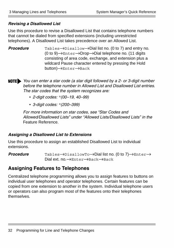
Revising a Disallowed List
Use this procedure to revise a Disallowed List that contains telephone numbers that cannot be dialed from specified extensions (including unrestricted telephones). A Disallowed List takes precedence over an Allowed List.
Procedure Tables→Disallow→Dial list no. (0 to 7) and entry no. (0 to 9)→Enter→Drop→Dial telephone no. (11 digits consisting of area code, exchange, and extension plus a wildcard Pause character entered by pressing the Hold button)→Enter→Back
Assigning a Disallowed List to Extensions
Use this procedure to assign an established Disallowed List to individual extensions.
Procedure Tables→DisallowTo→Dial list no. (0 to 7)→Enter→Dial ext. no.→Enter→Back→Back
Assigning Features to Telephones
Centralized telephone programming allows you to assign features to buttons on individual user telephones and operator telephones. Certain features can be copied from one extension to another in the system. Individual telephone users or operators can also program most of the features onto their telephones themselves.
You can enter a star code (a star digit followed by a 2- or 3-digit number before the telephone number in Allowed List and Disallowed List entries. The star codes that the system recognizes are:
• 2-digit codes: *(00—19, 40—99)
• 3-digit codes: *(200—399)
For more information on star codes, see “Star Codes and Allowed/Disallowed Lists” under “Allowed Lists/Disallowed Lists” in the Feature Reference.
32 Programming for Line and Telephone Changes
3 Managing Lines and TelephonesSystem Manager’s Quick Reference
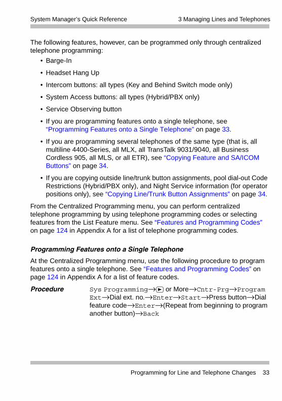
The following features, however, can be programmed only through centralized telephone programming:
• Barge-In
• Headset Hang Up
• Intercom buttons: all types (Key and Behind Switch mode only)
• System Access buttons: all types (Hybrid/PBX only)
• Service Observing button
• If you are programming features onto a single telephone, see “Programming Features onto a Single Telephone” on page 33.
• If you are programming several telephones of the same type (that is, all multiline 4400-Series, all MLX, all TransTalk 9031/9040, all Business Cordless 905, all MLS, or all ETR), see “Copying Feature and SA/ICOM Buttons” on page 34.
• If you are copying outside line/trunk button assignments, pool dial-out Code Restrictions (Hybrid/PBX only), and Night Service information (for operator positions only), see “Copying Line/Trunk Button Assignments” on page 34.
From the Centralized Programming menu, you can perform centralized telephone programming by using telephone programming codes or selecting features from the List Feature menu. See “Features and Programming Codes” on page 124 in Appendix A for a list of telephone programming codes.
Programming Features onto a Single Telephone
At the Centralized Programming menu, use the following procedure to program features onto a single telephone. See “Features and Programming Codes” on page 124 in Appendix A for a list of feature codes.
Procedure Sys Programming→ or More→Cntr-Prg→Program Ext→Dial ext. no.→Enter→Start→Press button→Dial feature code→Enter→(Repeat from beginning to program another button)→Back
Programming for Line and Telephone Changes 33
3 Managing Lines and Telephones System Manager’s Quick Reference
Copying Feature and SA/ICOM Buttons
Use the Copy Extension feature to copy an extension’s programmed buttons (with some exceptions) to one or more extensions. Program the features individually on an extension to create a template that can then be copied to other extensions in the system.
Only extensions of the same type can be copied to one another (that is, multiline 4400-Series to multiline 4400-Series, MLX to MLX, TransTalk to TransTalk, Business Cordless 905 to Business Cordless 905, MLS to MLS, and ETR to ETR) because the four telephones have different button layouts. You need one template for each type of telephone in your system.
A Multi-Function Module’s (MFM) programming can be copied to or from another MFM. A Direct Line Console (DLC) can be copied only to another DLC. Single-line telephone and QCC features cannot be copied.
For features that can be copied, see “Copy Extension” in the Feature Reference.
Procedure or More→Cntr-Prg→Copy Ext→Dial copy from ext. no.→ Enter→Dial copy to ext. no.→Enter→(Return to “Dial copy from ext. no.” to copy another extension)
Copying Line/Trunk Button Assignments
Use this procedure to copy outside line/trunk button assignments, pool dial-out code restrictions (Hybrid/PBX only), and Night Service information (for operator positions only). You can copy from one extension to another or to a block of extensions with identical requirements.
If you are copying assignments from an operator position to a block of extensions that includes both operator and non-operator extensions, the information is copied only to the operator positions; the non-operator positions are not affected. Similarly, if you are copying assignments from a non-operator position to a block of extensions that includes both operator and non-operator extensions, the information is copied only to the non-operator positions; the operator positions are not affected. The system does not provide an error tone to signal that the copy did not work for all of the extensions in the block.
34 Programming for Line and Telephone Changes
3 Managing Lines and TelephonesSystem Manager’s Quick Reference
Procedure To copy to a single extension:
Extensions→Line Copy→Single→Dial copy from ext. no.→Enter→Dial copy to ext. no.→Enter→Back→Back
To copy to a block of extensions:
Extensions→Line Copy→Block→Dial copy from ext. no.→Enter→Dial ext. no. of first telephone in block→ Enter→Dial ext. no. of last telephone in block→Enter→ Back→Back
Programming for Line and Telephone Changes 35
3 Managing Lines and Telephones System Manager’s Quick Reference
36 Programming for Line and Telephone Changes
4 Managing DLC and QCC OperatorPositions
Contents
Overview. . . . . . . . . . . . . . . . . . . . . . . . . . . . . . . . . . . . . . . . . . . . . . .37Assigning a DLC Operator Position . . . . . . . . . . . . . . . . . . . . . . . . . 38Assigning a QCC Operator Position . . . . . . . . . . . . . . . . . . . . . . . . . .38Assigning QCC Operator to Receive Calls . . . . . . . . . . . . . . . . . .39Assigning QCC Queue Priority Level . . . . . . . . . . . . . . . . . . . . . . .39
Adding Optional Operator Features . . . . . . . . . . . . . . . . . . . . . . . . . .40Setting Operator Hold Timer . . . . . . . . . . . . . . . . . . . . . . . . . . . . .41Enabling the DLC Operator Automatic Hold . . . . . . . . . . . . . . . . .41Programming Hold Return . . . . . . . . . . . . . . . . . . . . . . . . . . . . . . .41Programming Automatic Hold or Release . . . . . . . . . . . . . . . . . . .42Setting Queue over Threshold . . . . . . . . . . . . . . . . . . . . . . . . . . . .42Programming Elevate Priority . . . . . . . . . . . . . . . . . . . . . . . . . . . .42Programming Calls-In-Queue Alert . . . . . . . . . . . . . . . . . . . . . . . .42Programming a QCC Operator to Receive Call Types . . . . . . . . .43Assigning QCC Call Type Queue Priority Level. . . . . . . . . . . . . . .43Enabling Voice Announce . . . . . . . . . . . . . . . . . . . . . . . . . . . . . . .44Programming for Message Center Operation . . . . . . . . . . . . . . . .44Programming for Extended Call Completion . . . . . . . . . . . . . . . . .45Setting Return Ring . . . . . . . . . . . . . . . . . . . . . . . . . . . . . . . . . . . .45Programming for Position Busy Backup . . . . . . . . . . . . . . . . . . . .46
4 Managing DLC and QCC OperatorPositions
OverviewThis chapter provides procedures to assign a Direct-Line Console (DLC) or Queued Call Console (QCC) operator position, as well as to assign features to the operator positions. Prior to assigning a DLC or QCC operator position, you must make decisions about which features and buttons to assign to the operator’s telephone. See “About Adding/Removing a Telephone” on page 26.
For a detailed discussion of system operator positions, see “Direct-Line Console” and “Queued Call Console” in the Feature Reference.
Overview 37
4 Managing DLC and QCC Operator Positions System Manager’s Quick Reference
Assigning a DLC Operator PositionUse this procedure to assign DLC operator positions to the first and fifth extension jacks on an 008 MLX, 408 GS/LS-ID-MLX, or 412 LS-ID-TDL module. You also can assign DLC positions to the first, fifth, ninth, and thirteenth extension jacks on a 016 MLX module, and to the first, fifth, thirteenth, and seventeenth extension jacks on a 024 TDL module. You cannot assign a DLC operator position on an ETR module.
The first jack on the first extension module in your system is automatically assigned as the primary operator position.
Procedure Operator→Positions→Direct Line→Dial ext. no.→ Enter or Delete→Store All
Assigning a QCC Operator PositionUse this procedure to assign a QCC operator position to the first and fifth extension jacks on a 008 MLX, 408 GS/LS-ID-MLX, or 412 LS-ID-TDL module. You also can assign an QCC position to the first, fifth, ninth, and thirteenth extension jacks on a 016 MLX module, and to the first, fifth, thirteenth, and seventeenth extension jacks on a 024 TDL module. The first jack on the first MLX or TDL extension module in your system is automatically assigned as the primary operator position. QCC button assignments are automatic and factory-set.
QCC operators serve as central answering positions for all incoming calls. Incoming calls are held in the QCC queue and are directed to each QCC operator in a prioritized sequence. The calls are received one at a time, regardless of the number of incoming calls to the system.
A system forced idle occurs when you perform this task.
A system forced idle occurs when you perform this task.
38 Assigning a DLC Operator Position
4 Managing DLC and QCC Operator PositionsSystem Manager’s Quick Reference
Procedure Operator→Positions→Queued Call→Dial ext. no.→ Enter or Delete→Store All
Assigning QCC Operator to Receive Calls
Use this procedure to specify whether or not incoming calls on each line/trunk ring into the QCC queue and to identify the QCC system operator positions that receive incoming calls on each line/trunk.
Procedure To program a single line/trunk:
LinesTrunks→ or More→QCC Oper→Dial ext. no.→ Enter→Select entry mode→Dial line/trunk no.→Enter→ Back→Back
To program a block of lines/trunks:
LinesTrunks→ or More→QCC Oper→Dial ext. no.→ Enter→Select block of lines/trunks→Toggle LED On/Off→ Enter→Back→Back
Assigning QCC Queue Priority Level
Use this procedure to assign QCC queue priority level values (1 to 7) to each loop-start, ground-start, and automatic-in tie trunk in your system. The value assigned determines the order in which calls are sent to the QCC operator positions. Call priority 1 is the highest priority, and 7 is the lowest priority. The default value is 4.
Procedure To program a single line/trunk:
LinesTrunks→ or More→QCC Prior→Dial priority level (1 to 7)→Enter→Select entry mode→Dial trunk no.→Enter→Back→Back
To program a block of lines/trunks:
LinesTrunks→ or More→QCC Prior→Dial priority level (1 to 7)→Enter→Select block of lines→Toggle LED on/off→Enter→Back→Back
Assigning a QCC Operator Position 39
4 Managing DLC and QCC Operator Positions System Manager’s Quick Reference
Adding Optional Operator FeaturesIn Hybrid/PBX mode, you can add the following features to the DLC and/or QCC operator positions.
• You can add Operator Hold Timer to both the DLC and QCC operator positions.
• You can add DLC Operator Automatic Hold only to DLC operator positions.
• You can add the following features only to QCC operator positions:
– Hold Return
– Automatic Hold or Release
– Queue over Threshold
– Elevate Priority
– Calls-in-Queue Alert
– QCC Operator to Receive Call Types
– Call Type Queue Priority Level
– Voice Announce
– Message Center Operation
– Automatic or Manual Extended Call Completion
– Return Ring
– Position-Busy Backup
Some of these options cannot be programmed for an individual operator position, but rather for all operator positions in the system. These are: Operator Hold Timer, Hold Return, Automatic Hold or Release, Extended Call Completion, Return Ring, Queue over Threshold, Elevate Priority, and QCC Operator to Receive Call Types. In addition, only one Position-Busy Backup can be programmed per system.
40 Adding Optional Operator Features
4 Managing DLC and QCC Operator PositionsSystem Manager’s Quick Reference
Setting Operator Hold Timer
Use this procedure to set the length of the operator Hold Timer for all DLCs and QCCs. If the system operator does not pick up the call within the time programmed, an abbreviated ring reminds the operator that a call is being held.
This option cannot be programmed for individual operator positions.
Procedure Operator→Hold Timer→Drop→Dial no. of seconds (10 to 255 seconds)→Enter→Back
Enabling the DLC Operator Automatic Hold
Use this procedure to enable or disable the DLC Operator Automatic Hold feature for DLC operator positions. When this feature is enabled, it prevents accidental call disconnection.
Procedure Operator→DLC Hold→Automatic Hold Enable or Automatic Hold Disable→Enter→Back
Programming Hold Return
Use this procedure to determine whether calls on hold are returned to the QCC queue or remain on hold on the QCC operator console after the Hold Timer has expired twice. After the Hold Timer expires the first time, the operator hears an abbreviated ring as a call-on-hold reminder. If another call is received at the same time that the Hold Timer expires, 10 seconds are added to the programmed operator Hold Timer Interval for the first call. If the QCC operator does not pick up a call by the time the Hold Timer expires twice, the call can be programmed to either remain on hold or return to the QCC queue.
This option cannot be programmed for individual QCC operator positions. The single setting applies to all QCC operator positions.
Procedure Operator→Queued Call→Hold Rtrn→Return to Queue or Remain on Hold→Enter→ Back→Back
Adding Optional Operator Features 41
4 Managing DLC and QCC Operator Positions System Manager’s Quick Reference
Programming Automatic Hold or Release
Use this procedure to specify whether a call in progress (on a Call button) is automatically put on hold (Automatic Hold) or disconnected (Automatic Release) when the operator presses another button.
This option cannot be programmed for individual QCC operator positions. The single setting applies to all QCC operator positions.
Procedure Operator→Queued Call→HoldRelease→Auto Hold or Auto Release→Enter→Back→Back
Setting Queue over Threshold
Use this procedure to specify the maximum number of calls (Threshold) in the QCC queue before system operators are notified with a tone that the Threshold has been reached or exceeded. If the Threshold is set to 0, operators are not notified.
Procedure Operator→Queued Call→Threshold→Drop→Dial no. of calls (0 to 99)→Enter→Back→Back
Programming Elevate Priority
Use this procedure to specify the length of time before calls waiting in the QCC queue are automatically reprioritized to a higher level. If priority is set to 0, calls are not prioritized.
Procedure Operator→QueuedCall→ElvatePrior→Drop→Dial no. of seconds (0 for same priority or 5 to 30)→Enter→Back→Back
Programming Calls-In-Queue Alert
Use this procedure to specify whether each QCC operator is notified (with a single beep) when a new call enters the QCC queue.
Procedure Operator→Queued Call→InQue Alert→Dial ext. no.→Enter→InQue Alert Enable or InQue Alert Disable→Enter→Back→Back
42 Adding Optional Operator Features
4 Managing DLC and QCC Operator PositionsSystem Manager’s Quick Reference
Programming a QCC Operator to Receive Call Types
Use this procedure to specify which QCC operators receive the following types of calls:
• Dial 0 calls (internal calls to the system operator).
• DID calls to invalid destinations (unassigned extension numbers).
• Calls to the Listed Directory Number (extension for the QCC queue).
• Calls programmed to return to the QCC queue (returning from directing, camped-on, held calls, and operator parked calls).
• Group Coverage calls.
• Forward/Follow Me calls.
The QCC queue can be a receiver for the maximum number of coverage groups (30).
Procedure Operator→Queued Call→Call Types→Select a call type→Operator→Dial coverage group no.→Enter→Dial ext. no.→Enter→Back→Back→Back→Back→Back
Assigning QCC Call Type Queue Priority Level
Use this procedure to assign a priority value (1 to 7) that determines the order in which calls programmed to ring into the QCC queue are sent to QCC system operator positions. A value of 1 is the highest priority. The default value is 4. The QCC queue priority level is assigned for the following types of calls:
• Dial 0 calls (internal calls to the system operator).
• DID calls to invalid destinations (unassigned extension numbers).
• Calls to the Listed Directory Number (extension for the QCC queue).
• Calls programmed to return to the QCC queue (returning from extending, camped-on, held calls, and operator parked calls).
• Group Coverage calls.
• Calls signed in (Follow) or forwarded to the system operator.
• Calls to a system operator extension number.
Adding Optional Operator Features 43
4 Managing DLC and QCC Operator Positions System Manager’s Quick Reference
This procedure does not include programming the QCC queue priority level for individual lines or trunks to ring into the queue. See “Assigning QCC Queue Priority Level” on page 39.
Procedure Operator→Queued Call→Call Types→Select call type→Priority→Drop→Dial priority level (1 to 7)→Enter→Back→Back→Back→Back
Enabling Voice Announce
Use this procedure to enable or disable Voice Announce for the QCC.
When Voice Announce is enabled, every QCC in the system has one Voice Announce Call button, the Call 5 (Ring/Voice) button. All Intercom calls that originate from a QCC Call 5 (Ring/Voice) button are delivered as Voice Announce calls.
When Voice Announce is disabled, all Intercom calls originating at the QCC Call buttons are Intercom Ringing calls.
Procedure Operator→Queued Call→ or More→Voice Annc→Enabled or Disabled→Enter→Back→Back
Programming for Message Center Operation
Use this procedure to designate one or more QCC operator positions to operate as a Message Center. The following options are automatically set for the Message Center position:
• Incoming calls are not directed to this position.
• Returning calls are directed to this position (return from extending and operator parked calls).
• All Group Coverage calls are directed to this position.
• All DID calls to invalid destinations are directed to this position.
Designating message center operation does not change any call type option programming, except that the call types mentioned above are added to the calls received at the QCC Message Center.
Procedure Operator→Queued Call→Msg Center→Dial QCC ext. no.→Enter→Back→Back→Back
44 Adding Optional Operator Features
4 Managing DLC and QCC Operator PositionsSystem Manager’s Quick Reference
Programming for Extended Call Completion
Use this procedure to specify one of the two basic options shown below for QCC operator positions with a DSS only:
• Automatic Completion. Allows one-touch call transfer–that is, calls are transferred by touching only an extension button on the DSS. The operator does not have to press the Release button.
• Manual Completion. QCC operators must press the Release button to complete the transfer when transferring a call using a DSS.
This option cannot be programmed for individual QCC operator positions. The setting applies to all QCC operator positions.
Procedure Operator→Queued Call→ExtndComplt→Automatic Complete or Manual Complete→Enter→Back→Back
Setting Return Ring
Use this procedure to specify the number of rings before an unanswered directed call is returned to the QCC queue or QCC Message Center position.
This option cannot be programmed for individual QCC operator positions. The setting applies to all QCC operator positions.
Procedure Operator→Queued Call→Return Ring→Drop→Dial no. of rings (1 to 15)→Enter→Back→Back
If you want unanswered calls to proceed to Voice Mail, lengthen the Return Ring setting.
Adding Optional Operator Features 45
4 Managing DLC and QCC Operator Positions System Manager’s Quick Reference
Programming for Position Busy Backup
Use this procedure to designate or remove the Calling Group to provide the backup position for the QCC queue. The specified Calling Group receives incoming calls when all QCC operator positions are in Position Busy mode.
Position Busy Backup is programmed for the QCC queue rather than for individual QCC operator positions. The Calling Group designated as the QCC queue backup serves as the backup for the Remote Access feature and as backup when the QCC is being used as the system programming console.
Only one Position Busy Backup can be programmed per system.
Procedure Operator→Queued Call→ or More→QCC Backup→Drop→Dial ext. number→Enter or Delete→Back→Back
46 Adding Optional Operator Features

5 Connecting Auxiliary Equipment
Contents
Overview. . . . . . . . . . . . . . . . . . . . . . . . . . . . . . . . . . . . . . . . . . . . . . .47Programming for Music-On-Hold . . . . . . . . . . . . . . . . . . . . . . . . . . . 48Programming for Loudspeaker Paging . . . . . . . . . . . . . . . . . . . . . . . .48Programming for Fax Machines . . . . . . . . . . . . . . . . . . . . . . . . . . . . .49Programming for Maintenance Alarms . . . . . . . . . . . . . . . . . . . . . . . .49
5 Connecting Auxiliary Equipment
OverviewThis chapter provides procedures to program line/trunk or extension jacks used for auxiliary equipment and applications–for example, a music source for Music-On-Hold, loudspeaker paging equipment, maintenance alarms, or a fax machine.
Overview 47
5 Connecting Auxiliary Equipment System Manager’s Quick Reference
Programming for Music-On-HoldUse this procedure to identify the line/trunk jack reserved for connection of a music source, such as a radio, tape player, or stereo system. Only one Music-On-Hold line/trunk jack is allowed per system. Note the following conditions:
• You cannot assign the line/trunk identified for Music-On-Hold to a line/trunk pool. If the line/trunk is currently assigned to a pool, you must remove it before you program this option.
• You cannot assign the line/trunk identified for use with Music-On-Hold to a button on any telephone or as a Remote Access trunk.
• You cannot use the line/trunk jack identified for Music-On-Hold for a loudspeaker paging system or maintenance alarm.
Each system in a private network must have its own music source. A music source connected to a remote private networked switch cannot be used by the local system.
Procedure AuxEquip→MusicOnHold→Dial line/trunk no.→ Enter→ Back
Programming for Loudspeaker PagingUse this procedure to identify the line/trunk jack reserved for connection of loudspeaker paging equipment. A maximum of three single-zone or multizone loudspeaker paging systems can be connected to the system. Note the following conditions:
• You cannot assign the line/trunk identified for loudspeaker paging equipment use to a line/trunk pool. If the line/trunk is currently assigned to a pool, you must remove it before you program this option.
• You cannot assign the line/trunk identified for loudspeaker paging equipment use as a Remote Access line/trunk.
• You cannot use its jack for Music-On-Hold or maintenance alarm.
Procedure AuxEquip→Ldspkr Pg→Dial line/trunk no.→Enter→Back
48 Programming for Music-On-Hold
5 Connecting Auxiliary EquipmentSystem Manager’s Quick Reference
Programming for Fax MachinesUse this procedure to assign the extension jack used to connect the fax machine. To remove a fax machine and free the extension jack for another use, you must remove the extension jack assignment.
In addition, you can specify the extensions to receive a Message-Waiting Indication (MWI) when a fax transmission is received, as well as the length of time before the system registers that a fax has arrived and sends the MWI.
A maximum of 16 fax machines can use the Fax Message Waiting feature. Additional fax machines (more than 16) can be installed, but these machines cannot use this feature.
You can specify up to four telephones to receive the MWI when a fax transmission is received. Fax machines can only send and not receive MWIs.
Procedure To program an extension for a fax machine:
AuxEquip→Fax→Extension→Dial ext. no.→ Enter→Back
To have a message waiting light for a fax machine:
Fax→Extension→Dial ext. no.→Enter→ Back→Msg Waiting→Dial fax machine ext. no.→ Enter→Dial MWI ext. no.→Enter→Threshold→Drop→Dial no. of seconds (0 to 30)→Enter→Back→Back
Programming for Maintenance AlarmsUse this procedure to identify the line/trunk jack that connects an external alerting device that sounds or flashes when major maintenance problems occur.
You cannot assign the line/trunk identified for the maintenance alarm to a button on any telephone or as a Remote Access trunk, and you cannot use its line/trunk jack to connect a loudspeaker paging system or Music-On-Hold.
Procedure AuxEquip→MaintAlarms→Dial line/trunk no.→Enter→Back
Programming for Fax Machines 49
5 Connecting Auxiliary Equipment System Manager’s Quick Reference
50 Programming for Maintenance Alarms

6 Managing Group Features
Contents
Overview. . . . . . . . . . . . . . . . . . . . . . . . . . . . . . . . . . . . . . . . . . . . . . .51Changing Group Calling Member Assignments . . . . . . . . . . . . . . . . .51Changing Group Coverage Member Assignments . . . . . . . . . . . . . . .51Changing Coverage Delay Rings . . . . . . . . . . . . . . . . . . . . . . . . . . . .52
6 Managing Group Features
OverviewThis chapter provides procedures to change group calling member assignments, group coverage member assignments, and coverage delay rings.
Changing Group Calling Member AssignmentsUse this procedure to assign or remove an extension to or from a Calling Group. A Calling Group is used to direct calls to a group of people who all handle the same type of call. A single extension number is assigned to the group and is used by both inside and outside callers to reach the group.
Procedure Extensions→ or More→Grp Calling→Members→Dial Calling Group ext. no.→Enter→Dial ext. no.→Enter→Back→Back→Back
Changing Group Coverage Member AssignmentsUse this procedure to assign or remove an extension to or from a Coverage Group. A Coverage Group is a group of senders. Coverage is an arrangement in which calls from a group of senders are redirected to one or more receivers.
Overview 51
6 Managing Group Features System Manager’s Quick Reference
Procedure Extensions→ or More→Group Cover→Dial group no. (1 to 30)→Enter→Dial ext. no.→ Enter→Back→Back
Changing Coverage Delay RingsUse this procedure to change coverage delay rings at an extension. Coverage delay is specified by ring delay settings for each extension.
The Feature Reference provides a full description of Coverage options, including detailed tables and illustrations. Before programming Coverage Delays, you should review this information.
Procedure Change the number of rings before a call is sent to Group Coverage receivers:
Extensions→ or More→ or More→Cover Delay→Group→Dial sender’s ext. no.→Enter→Dial no. of rings (1 to 9)→Enter→Back→Back
Change the delay for Primary Cover buttons programmed for Delay Ring; change the additional delay before a call is sent to Group Coverage receivers when Primary or Secondary Coverage Receivers are available:
Extensions→ or More→ or More→Cover Delay→ Primary→Dial sender’s ext. no.→Enter→Dial no. of rings (1 to 6)→Enter→Back→Back
Change the delay for Secondary Cover buttons programmed for Delay Ring:
Extensions→ or More→ or More→Cover Delay→ Secondary→Dial sender’s ext. no.→Enter→Dial no. of rings (1 to 6)→Enter→Back→Back
52 Changing Coverage Delay Rings

7 Managing Night Service Features
Contents
Overview. . . . . . . . . . . . . . . . . . . . . . . . . . . . . . . . . . . . . . . . . . . . . . .53Revising Night Service with Group Assignments . . . . . . . . . . . . . . . .53Revising Night Service with Coverage Control . . . . . . . . . . . . . . . . . .54
7 Managing Night Service Features
OverviewThis chapter provides procedures to revise Night Service with group assignments and with coverage control.
Revising Night Service with Group AssignmentsUse this procedure to add or remove extensions, lines, and a Calling Group to a Night Service group for after-hours coverage.
Procedure To assign a Calling Group to a Night Service group:
NightSrvce→GroupAssign→CallingGroup→Dial ext. no. of Night Service operator→Enter→Dial Calling Group no.→Enter→Back→Back
To assign an extension to a Night Service group:
NightSrvce→GroupAssign→Extensions→Dial ext. no. of Night Service operator→Enter→Dial ext. no. of member→Enter→Back→Back
To assign a line to a Night Service group:
NightSrvce→GroupAssign→Lines→Dial ext. no. of Night Service operator→Enter→Dial outside line no. (801—880)→Enter→Back→Back
Overview 53
7 Managing Night Service Features System Manager’s Quick Reference
Revising Night Service with Coverage ControlUse this procedure to coordinate the status of Coverage VMS buttons programmed at extensions with Night Service operation.
With this feature enabled (the factory setting is disabled), the following occurs:
• When Night Service is turned On, all Coverage VMS buttons are activated–that is, the programmed voice-messaging system Calling Group takes calls.
• When Night Service is turned Off and normal operation is resumed, all Coverage VMS buttons are activated. Calls follow normal coverage patterns for business-hours operation.
Procedure To enable or disable Night Service with Coverage Control:
NightSrvce→Cover Control→Enable or Disable→ Enter→Back
54 Revising Night Service with Coverage Control
8 Changing Labels
Contents
Overview. . . . . . . . . . . . . . . . . . . . . . . . . . . . . . . . . . . . . . . . . . . . . . .55Changing Extension Directory Labels. . . . . . . . . . . . . . . . . . . . . . . . .55Changing Trunk Labels. . . . . . . . . . . . . . . . . . . . . . . . . . . . . . . . . . . 56Changing Posted Message Labels . . . . . . . . . . . . . . . . . . . . . . . . . . .56Changing Calling Group Labels . . . . . . . . . . . . . . . . . . . . . . . . . . . . 57Changing System Speed Dial Labels . . . . . . . . . . . . . . . . . . . . . . . . .57
8 Changing Labels
OverviewThis chapter provides procedures to change labels for Extension Directories, Lines or Trunks, Posted Messages, Group Calling, and System Speed Dial Directories.
Changing Extension Directory LabelsUse this procedure to change the alphanumeric system labels, so that display telephone users can identify the co-worker who is calling or leaving a message or to program the Extension Directory feature for 4400-Series or MLX telephones.
A label may have a maximum of seven characters. Labels may contain capital letters, numbers, and eight types of characters: ampersands (&), dashes (-), spaces, periods (.), commas (,), apostrophes (‘), stars (*), and pound signs (#).
Procedure or More→Labeling→Directory→Extension→Dial ext. no.→Enter→Drop→Dial label (up to 7 characters)→ Enter→Back→Back→Back
Overview 55
8 Changing Labels System Manager’s Quick Reference
Changing Trunk LabelsUse this procedure to establish alphanumeric system labels for display telephone users to identify the line or trunk being used.
Each label may have a maximum of seven characters. Labels may contain capital letters, numbers, and eight types of characters: ampersands (&), dashes (-), spaces, periods (.), commas (,), apostrophes (‘), stars (*), and pound signs (#).
Procedure or More→Labeling→LinesTrunks→Dial line/trunk no.→ Enter→Drop→Dial label (up to 7 characters)→Enter→Back→Back
Changing Posted Message LabelsUse this procedure to change existing posted messages. Posted messages allow callers with display telephones to know why the called extension does not answer.
Each posted message may have a maximum of 16 characters. Labels may contain capital letters, numbers, and eight types of characters: ampersands (&), dashes (-), spaces, periods (.), commas (,), apostrophes (‘), stars (*), and pound signs (#).
Procedure or More→Labeling→PostMessage→Dial message no. (1 to 20)→Enter→Drop→Dial message (up to 16 characters)→Enter→Back→Back
56 Changing Trunk Labels
8 Changing LabelsSystem Manager’s Quick Reference
Changing Calling Group LabelsUse this procedure to change alphanumeric system labels for display telephone users to identify Calling Groups.
Each label may have a maximum of seven characters. Labels may contain capital letters, numbers, and eight types of characters: ampersands (&), dashes (-), spaces, periods (.), commas (,), apostrophes (‘), stars (*), and pound signs (#).
Procedure or More→Labeling→Grp Calling→Dial Calling Group ext. no.→Enter→Drop→Dial label (up to 7 characters)→Enter→Back→Back
Changing System Speed Dial LabelsUse this procedure to change System Speed Dial numbers for all system users. You can also use this procedure to change the alphanumeric labels shown on the MLX display telephones.
There may be a total of 130 numbers, with a maximum of 11 characters per label. Labels may contain capital letters, numbers, and eight types of characters: ampersands (&), dashes (-), spaces, periods (.), commas (,), apostrophes (‘), stars (*), and pound signs (#).
Procedure or More→Labeling→Directory→System→Dial code no. (600 through 729)→Enter→Drop→Dial label (up to 11 characters)→Enter→Backspace→Dial telephone no.→Enter→Yes or No→Enter→Back→ Back→Back
Changing Calling Group Labels 57
8 Changing Labels System Manager’s Quick Reference
58 Changing System Speed Dial Labels

9 About Reports
Contents
Overview. . . . . . . . . . . . . . . . . . . . . . . . . . . . . . . . . . . . . . . . . . . . . . .59Printing SMDR Reports . . . . . . . . . . . . . . . . . . . . . . . . . . . . . . . . . . .61Printing System Programming Reports . . . . . . . . . . . . . . . . . . . . . . 62
9 About Reports
OverviewThe system generates a variety of reports that can help you with your system management tasks:
• The Station Message Detail Recording (SMDR) feature provides information about incoming and outgoing calls. The content of the report depends on which of two formats (Basic or ISDN) you select. The report can include the type of call (voice or data), the date, the time of the call, the called number, the duration of the call, the number of the trunk used to make or receive the call, and an account code, if applicable. This report prints on the SMDR printer.
• The system programming reports describe how various aspects of the system are programmed (for example, Trunk Information, Label Information, Allowed and Disallowed Lists, and Pickup Groups). There is also an Error Log that describes any system errors that may occur. You access these reports from the System Programming menu.
The available system programming reports are listed below. With the exception of Trunk Information, the dash items under the bullets show the sections of each report that automatically print when that report option is selected.
• All
– Each report
– All report options
• System Setup (System Information Report)
Overview 59
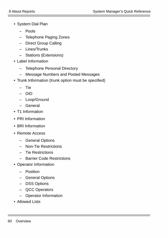
9 About Reports System Manager’s Quick Reference
• System Dial Plan
– Pools
– Telephone Paging Zones
– Direct Group Calling
– Lines/Trunks
– Stations (Extensions)
• Label Information
– Telephone Personal Directory
– Message Numbers and Posted Messages
• Trunk Information (trunk option must be specified)
– Tie
– DID
– Loop/Ground
– General
• T1 Information
• PRI Information
• BRI Information
• Remote Access
– General Options
– Non-Tie Restrictions
– Tie Restrictions
– Barrier Code Restrictions
• Operator Information
– Position
– General Options
– DSS Options
– QCC Operators
– Operator Information
• Allowed Lists
60 Overview
9 About ReportsSystem Manager’s Quick Reference
• Allowed Lists Assigned to Extensions
• Disallowed Lists
• Disallowed Lists Assigned to Extensions
• Automatic Route Selection
• Tables
• Extension Directory
• System Directory
• Group Page
• Extension Information
• Group Coverage
• Group Calling
• Night Service
• Call Pickup Groups
• Error Logs
• Authorization Codes
Printing SMDR ReportsStation Message Detail Recording (SMDR) reports print automatically on a serial printer connected to the SMDR jack on the control unit. The reports contain sequential call records.
If the printer is off, is out of paper, or has a paper jam, up to 100 SMDR records can be stored in the SMDR queue. The printing of system programming reports takes precedence; while these reports are printing, SMDR records are stored in the queue.
For more information, see “Station Message Detail Recording (SMDR)” in the Feature Reference.
Printing SMDR Reports 61
9 About Reports System Manager’s Quick Reference
Printing System Programming ReportsUse this procedure to print System Programming reports. System Programming reports can be printed out or viewed on the screen of a PC with WinSPM or printed out on a serial printer connected to the SMDR jack on the processor module in the control unit.
You can print individual reports or use the All option to print the entire set of available reports, including all report sections and options.
For more information, see “Station Message Detail Recording” in the Feature Reference. Appendix F of the Feature Reference provides samples of the reports.
Procedure To print trunk information:
or More→Print→Trunk Info→Select trunk type→ Exit
To print extension information:
or More→Print→More→Ext Info→Dial ext. no.→ Enter→Exit
To print all other reports:
or More→Print→Select report→Exit
• The Extension Information report incorrectly lists MLX-16DP telephones as MLX-28D telephones. If you have MLX-16DP telephones, keep a separate log of the extension numbers.
• MLS-6 and ETR-6 telephones are both reported as MLS/ETR telephones. TransTalk 9031, TransTalk 9040 when connected to an ETR port, and Business Cordless 905 telephones are identified as MLS-12D telephones.
62 Printing System Programming Reports
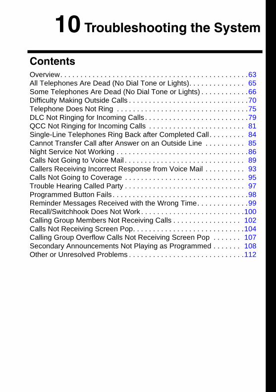
10 Troubleshooting the System
Contents
Overview. . . . . . . . . . . . . . . . . . . . . . . . . . . . . . . . . . . . . . . . . . . . . . .63All Telephones Are Dead (No Dial Tone or Lights). . . . . . . . . . . . . . 65Some Telephones Are Dead (No Dial Tone or Lights) . . . . . . . . . . . .66Difficulty Making Outside Calls . . . . . . . . . . . . . . . . . . . . . . . . . . . . . .70Telephone Does Not Ring . . . . . . . . . . . . . . . . . . . . . . . . . . . . . . . . .75DLC Not Ringing for Incoming Calls . . . . . . . . . . . . . . . . . . . . . . . . . .79QCC Not Ringing for Incoming Calls . . . . . . . . . . . . . . . . . . . . . . . . 81Single-Line Telephones Ring Back after Completed Call. . . . . . . . . 84Cannot Transfer Call after Answer on an Outside Line . . . . . . . . . . 85Night Service Not Working . . . . . . . . . . . . . . . . . . . . . . . . . . . . . . . . .86Calls Not Going to Voice Mail . . . . . . . . . . . . . . . . . . . . . . . . . . . . . . 89Callers Receiving Incorrect Response from Voice Mail . . . . . . . . . . 93Calls Not Going to Coverage . . . . . . . . . . . . . . . . . . . . . . . . . . . . . . 95Trouble Hearing Called Party . . . . . . . . . . . . . . . . . . . . . . . . . . . . . . 97Programmed Button Fails . . . . . . . . . . . . . . . . . . . . . . . . . . . . . . . . . .98Reminder Messages Received with the Wrong Time. . . . . . . . . . . . .99Recall/Switchhook Does Not Work . . . . . . . . . . . . . . . . . . . . . . . . . .100Calling Group Members Not Receiving Calls . . . . . . . . . . . . . . . . . 102Calls Not Receiving Screen Pop. . . . . . . . . . . . . . . . . . . . . . . . . . . .104Calling Group Overflow Calls Not Receiving Screen Pop . . . . . . . 107Secondary Announcements Not Playing as Programmed . . . . . . . 108Other or Unresolved Problems . . . . . . . . . . . . . . . . . . . . . . . . . . . . .112
10 Troubleshooting the System
OverviewThis chapter provides procedures for solving the most common problems that you may encounter with the MERLIN MAGIX system. You may be able to resolve a problem quickly and easily by following the appropriate steps.
For information about troubleshooting data and video communications, see the Data/Video Reference. For more information about troubleshooting a Computer Telephony Integration (CTI) link, see the PassageWay Telephony Services Network Manager’s Guide.
It is helpful to have the Feature Reference and system planning forms on hand to perform some procedures. If the procedure involves using system programming or centralized telephone programming to check a system or feature setting, the troubleshooting procedures indicate where in the Feature Reference you can find the programming steps.
You should also have available the System Information Sheet from the front of this quick reference.
Systems in Hybrid/PBX mode support private connections between MERLIN MAGIX Integrated Systems and a DEFINITY Enterprise Communications Server (ECS) or DEFINITY ProLogix Solutions systems using private networks or the public switched telephone network. This aspect of the system is not covered in this quick reference. For complete troubleshooting information, see the Network Reference.
Overview 63
10 Troubleshooting the System System Manager’s Quick Reference
WARNING:If you must check something on the control unit, proceed with caution. Do not stand on a box or chair to reach the unit if it is installed out of easy reach. If you do not have a stable ladder or other proper equipment, do not proceed; wait for the Avaya technician or authorized dealer.
• If power to the system is cut off, the system will retain its programming for four to five days after it stops receiving power. Then all of the system’s programmed settings may return to the factory settings.
• Be sure to change the system time appropriately when Daylight Savings Time starts and when it ends. System time affects the functioning of several system features–including Automatic Backup, Night Service, Station Message Detail Recording (SMDR) reports, stand-alone Auto Attendant systems, Voice Mail, and Reminder Service.
• For information about removing the control unit housing, contact your Avaya representative or authorized dealer.
64 Overview
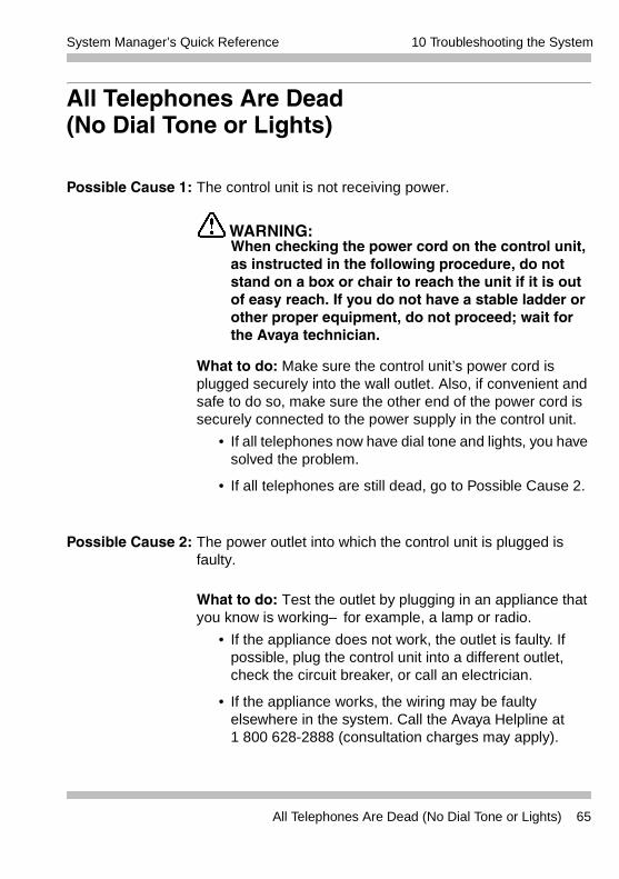
10 Troubleshooting the SystemSystem Manager’s Quick Reference
All Telephones Are Dead (No Dial Tone or Lights)
Possible Cause 1: The control unit is not receiving power.
WARNING:When checking the power cord on the control unit, as instructed in the following procedure, do not stand on a box or chair to reach the unit if it is out of easy reach. If you do not have a stable ladder or other proper equipment, do not proceed; wait for the Avaya technician.
What to do: Make sure the control unit’s power cord is plugged securely into the wall outlet. Also, if convenient and safe to do so, make sure the other end of the power cord is securely connected to the power supply in the control unit.
• If all telephones now have dial tone and lights, you have solved the problem.
• If all telephones are still dead, go to Possible Cause 2.
Possible Cause 2: The power outlet into which the control unit is plugged is faulty.
What to do: Test the outlet by plugging in an appliance that you know is working–for example, a lamp or radio.
• If the appliance does not work, the outlet is faulty. If possible, plug the control unit into a different outlet, check the circuit breaker, or call an electrician.
• If the appliance works, the wiring may be faulty elsewhere in the system. Call the Avaya Helpline at1 800 628-2888 (consultation charges may apply).
All Telephones Are Dead (No Dial Tone or Lights) 65
10 Troubleshooting the System System Manager’s Quick Reference
Some Telephones Are Dead (No Dial Tone or Lights)
Possible Cause 1: The telephones are not receiving power.
What to do: Check that each telephone is plugged into a telephone wall jack that you know is working.
• If the telephones now have dial tones and lights, there may be a problem with the system wiring or the control unit associated with the faulty telephone or telephones. Call the Avaya Helpline at 1 800 628-2888 (consultation charges may apply).
• If the telephones are still dead, go to Possible Cause 2.
Possible Cause 2: For single-line telephones, the Idle Line Selection may be set incorrectly. (If not a single-line telephone, go to Possible Cause 4.)
What to do: Use centralized telephone programming to ensure that the Ringing/Idle Line Preference is set to On (see “Automatic Line Selection” in the Feature Reference). Check to see whether the telephone now has dial tone.
• If the telephone receives a dial tone, you have solved the problem.
• If the telephone is still dead, go to Possible Cause 3.
66 Some Telephones Are Dead (No Dial Tone or Lights)
10 Troubleshooting the SystemSystem Manager’s Quick Reference
Possible Cause 3: For single-line telephones, the Automatic Line Selection may be set incorrectly; see “Automatic Line Selection” in the Feature Reference. (If not a single-line telephone, go to Possible Cause 4.)
What to do: Use centralized telephone programming to set the Automatic Line Selection for the extension. Check to see whether the telephone now has a dial tone.
• If the telephone receives a dial tone, you have solved the problem.
• If the telephone is still dead, go to Possible Cause 5.
WARNING:If you must check something on the control unit, proceed with caution. Do not stand on a box or chair to reach the unit if it is installed out of easy reach. If you do not have a stable ladder or other proper equipment, do not proceed; wait for the Avaya technician.
The following procedure may help Avaya Helpline technicians analyze your problem. You should not perform this procedure, however, unless you have experience removing the control unit cover and working with the control unit extension jacks. Before proceeding, consult System Planning Form 2a, System Numbering: Extension Jacks.
Some Telephones Are Dead (No Dial Tone or Lights) 67
10 Troubleshooting the System System Manager’s Quick Reference
Possible Cause 4: If an MLX telephone is not working, it may be plugged into an MLX extension jack that is programmed for CTI link.
What to do: Follow the procedure for printing an Extension Information Report to determine whether the jack is programmed for CTI link. See “CTI Link” in the Feature Reference for details.
• If the jack is programmed for a CTI link and you wish to retain the link, plug the MLX telephone into another available MLX jack.
• If the jack is programmed for a CTI link and you wish to remove the link programming, unplug the telephone from the MLX jack. Then see “CTI Link” in the Feature Reference for the correct procedure.
• If the jack is not programmed for a CTI link, go to Possible Cause 5.
Possible Cause 5: The telephones may be defective.
What to do: Test each telephone by replacing the dead telephone with a similar telephone that you know is working.
• If the replacement telephone receives a dial tone and its lights function, then replace it with the original telephone and check again. If the original telephone still does not receive a dial tone and its lights do not function, then the original telephone may be defective. Call the Avaya Helpline at 1 800 628-2888 (consultation charges may apply).
68 Some Telephones Are Dead (No Dial Tone or Lights)
10 Troubleshooting the SystemSystem Manager’s Quick Reference
• If the replacement telephone does not receive a dial tone and its lights do not function, there may be a problem with the system wiring or the control unit. To test one possible wiring problem, go to Possible Cause 6.
WARNING:If you must check something on the control unit, proceed with caution. Do not stand on a box or chair to reach the unit if it is installed out of easy reach. If you do not have a stable ladder or other proper equipment, do not proceed; wait for the Avaya technician.
Possible Cause 6: A module (or modules) may be defective.
What to do: Identify the control unit module (or modules) where the telephones are connected.
• If the telephones are all connected to one module, there may be a problem with the module. Call the Avaya Helpline at 1 800 628-2888 (consultation charges may apply).
• If the dead telephones are connected to modules that also connect to working telephones, test the jacks on the modules. Identify the port where each nonfunctional telephone is connected.
The following procedure may help Avaya Helpline technicians analyze your problem. You should not perform this procedure, however, unless you have experience removing the control unit cover and working with the control unit extension jacks. Before proceeding, consult System Planning Form 2a, System Numbering: Extension Jacks.
Some Telephones Are Dead (No Dial Tone or Lights) 69
10 Troubleshooting the System System Manager’s Quick Reference
Identify a second port in the same module connected to a working telephone and unplug the jack from the module. Plug the jack for the dead telephone into the extension jack that is now open. If the telephone works, call the Avaya Helpline at 1 800 628-2888 (consultation charges may apply).
• If the telephones do not work when plugged into module jacks that are known to be functioning, call the Avaya Helpline at 1 800 628-2888 (consultation charges may apply).
Difficulty Making Outside Calls
SECURITY ALERT:When changing calling restrictions and other security settings, take care not to compromise the security of your system. For more information, consult “Security of Your System: Preventing Toll Fraud” in Appendix A, “Customer Support Information,” of the Feature Reference.
Possible Cause 1: This extension is restricted from making outside calls.
What to do: Use system programming to check the extension’s Calling Restrictions, if any (see “Calling Restrictions in the Feature Reference). If the extension is toll- or outward-restricted, change it to unrestricted, if appropriate. Try again to make an outside call from the extension.
• If you can make outside calls from the extension, you have solved the problem.
• If you cannot make outside calls, go to Possible Cause 2.
70 Difficulty Making Outside Calls
10 Troubleshooting the SystemSystem Manager’s Quick Reference
Possible Cause 2: If the system (Hybrid/PBX mode) uses pool dial out codes, the extension may be restricted from dialing the pool dial out code.
What to do: Use system programming to determine whether the pool dial out code has been assigned for the extension (see “Calling Restrictions” in the Feature Reference).
• If the pool dial out code is missing, assign it, if appropriate, and try again to make an outside call. If you can, you have solved the problem. If you cannot, go to Possible Cause 3.
• If the pool dial-out code is not missing, go to Possible Cause 3.
Possible Cause 3: If the system (Hybrid/PBX mode) is set up for Automatic Route Selection (ARS), the extension’s Facility Restriction Level (FRL) may be set too low (see “Automatic Route Selection” in the Feature Reference). The extension’s FRL must be greater than or equal to the route’s FRL.
What to do: Use system programming to check the extension’s FRL.
• If the FRL is set to less than 6, increase the FRL to 6 and try again to make an outside call. If you can now make outside calls on the telephone, adjust the FRL as needed. You have solved the problem.
Difficulty Making Outside Calls 71
10 Troubleshooting the System System Manager’s Quick Reference
SECURITY ALERT:Changing the extension’s Facility Restriction Level may compromise the security of your system. If you leave the FRL at 6, ensure that the person at the extension is authorized to make toll calls. For more information, consult the section entitled “Automatic Route Selection” in the Feature Reference and “Security of Your System: Preventing Toll Fraud” in Appendix A, “Customer Support Information,” of the Feature Reference.
• If, after setting the FRL to 6, the problem persists, change the FRL back to the original setting and go to Possible Cause 4.
Possible Cause 4: ARS tables are not programmed correctly.
What to do: Use system programming to check for correct pools, correct digit manipulation (prepending, dropping, etc.), and correct type of call (data only, voice only, or both).
Possible Cause 5: A Disallowed List is assigned to the extension.
What to do: Use system programming to check whether a Disallowed List is assigned to the extension (see “Allowed/Disallowed Lists” in the Feature Reference).
• If a Disallowed List is assigned to the extension, remove it, if appropriate. Try again to make an outside call. If you can, you have solved the problem. If you cannot, go to Possible Cause 6.
Calls going across a private network may be affected by the improper setting of the FRL. See the Network Reference for details.
72 Difficulty Making Outside Calls
10 Troubleshooting the SystemSystem Manager’s Quick Reference
• If a Disallowed List is not assigned to the extension, go to Possible Cause 6.
Possible Cause 6: Night Service with Outward Restriction is activated.
What to do: Check to determine whether Night Service with Outward Restriction is activated by checking the light next to the Night Service button on the operator’s console.
• If the light is on, then Night Service is activated and there are restrictions on outside calls. Use the Night Service password, if known, or use system programming to put the extension on the Night Service Exclusion List, if appropriate. Finally, try again to make an outside call. If you can, you have solved the problem. If you cannot, go to Possible Cause 7.
SECURITY ALERT:Extensions on the Night Service Exclusion List have unrestricted calling privileges and are not protected from unauthorized after-hours use.
• If the light is off and Night Service is not activated, go to Possible Cause 7.
Possible Cause 7: Forced Account Code Entry is assigned to the extension.
What to do: Use system programming to determine whether Forced Account Code Entry is required for that extension (see “Account Code Entry” in the Feature Reference).
• If it is, remove the extension from the list of extensions required to use account codes, if appropriate. Try again to make an outside call. If you can, you have solved the problem. If you cannot, go to Possible Cause 8.
• If the extension is not on the list, go to PossibleCause 8.
Difficulty Making Outside Calls 73
10 Troubleshooting the System System Manager’s Quick Reference
Possible Cause 8: In Hotel mode, the extension may be restricted from making calls.
What to do: Check the Extension Status of the extension by observing its lights on the operator’s DLC. To do this, change the console from a normal operator position to a calling supervisor’s console by pressing the Feature button and dialing 32, then touching the Hold button. Check either the red light next to the extension’s DSS button or the green light next to the Auto Dial button programmed for the extension.
• If the light is flashing or on, the extension is restricted from making outside calls. To change the Extension Status to 0 and remove restrictions, press the Feature button and dial 760; then press the DSS button for the extension.
Change the console back to normal operator status by pressing the Feature button and dialing 32 and then pressing the Drop button. Try again to make an outside call. If you can, you have solved the problem. If you cannot, go to Possible Cause 9.
• If the light is off, change the console back to the normal operator position by pressing the Feature button and dialing 32 and then pressing the Drop button. Go to Possible Cause 9.
Possible Cause 9: The telephone may be defective.
What to do: Test the telephone by replacing it with a similar telephone that you know is working properly.
• If the replacement telephone can make outside calls, then replace it with the original telephone and check again. If the original telephone still cannot make outside calls, then it may be defective. Call the Avaya Helpline at 1 800 628-2888 (consultation charges may apply).
74 Difficulty Making Outside Calls
10 Troubleshooting the SystemSystem Manager’s Quick Reference
• If the replacement telephone cannot make outside calls, there may be a problem with the system wiring or the control unit. Call the Avaya Helpline at 1 800 628-2888 (consultation charges may apply).
Telephone Does Not Ring
Possible Cause 1: The telephone’s ringer volume control is set too low.
What to do: While the telephone is idle and the handset is in the cradle, adjust the volume control up. From another extension, dial the extension with the problem.
• If you can hear the telephone ring, you have solved the problem.
• If the telephone still does not ring, go to PossibleCause 2.
If you are dialing an outside number on a private-networked system, the problem may be that the PRI PSTN outgoing tables are not programmed correctly. See the Network Reference for details.
Telephone Does Not Ring 75
10 Troubleshooting the System System Manager’s Quick Reference
Possible Cause 2: The Do Not Disturb feature is turned On.
What to do: Check the green light next to the programmed Do Not Disturb button to determine whether Do Not Disturb is turned On.
• If the green light is on, then Do Not Disturb is turned On. Press the button to deactivate the feature and to turn the light off. From another extension, dial the problem extension. If the telephone rings, you have solved the problem. If not, go to Possible Cause 3.
• If the green light is not on, then Do Not Disturb is Off; go to Possible Cause 3.
Possible Cause 3: The Forward feature is turned On.
What to do: Turn Off the Forward feature. Use one of the following methods, depending on the type of telephone:
• At a 4400-Series, MLX, or TransTalk 9040 (when connected to a TDL port) telephone with a programmed Forward button, deactivate the feature and turn the light off by pressing the button (if the green light is on, indicating that the feature is active). From another extension, dial the extension with the problem. If the telephone rings, you have solved the problem. If the telephone still does not ring, go to Possible Cause 4.
• At a 4400-Series, MLX, or TransTalk 9040 (when connected to a TDL port) telephone without a programmed Forward button, deactivate Forward by pressing the Feature button and dialing 33 plus the extension number of the telephone that is not receiving calls. From another extension, dial the extension where the problem is. If the telephone rings, you have solved the problem. If the telephone still does not ring, go to Possible Cause 4.
76 Telephone Does Not Ring
10 Troubleshooting the SystemSystem Manager’s Quick Reference
• At a single-line telephone, deactivate Forward by dialing #33 plus the extension number of the single-line telephone. From another extension, dial the extension with the problem. If the telephone rings, you have solved the problem. If the telephone still does not ring, go to Possible Cause 4.
Possible Cause 4: The Ringing Options setting of the Ring Timing feature for the extension is programmed for No Ring or Delayed Ring.
What to do: Use centralized telephone programming or extension programming to check the Ringing Options setting for the extension (see “Ringing Options” in the Feature Reference).
• If the Ringing Options setting is No Ring or Delay Ring, change the setting to Immediate, if appropriate. From another extension, dial the problem extension. If the telephone now rings, you have solved the problem. If not, go to Possible Cause 5.
• If the Ringing Options setting is Immediate, go to Possible Cause 5.
You can check the Ringing Options setting at a 4400-Series or MLX display telephone by first pressing the Inspct button and then a line button. Ringing can be set for each line or for all lines. To change a setting, use extension programming. At a single-line telephone, check the Ringing Options settings for each line by using centralized telephone programming.
Telephone Does Not Ring 77
10 Troubleshooting the System System Manager’s Quick Reference
Possible Cause 5: The telephone may be defective.
What to do: Test the telephone by replacing it with a similar telephone that you know is working.
• If the replacement telephone rings, then replace it with the original telephone and check again. If the original telephone still does not ring, then the original telephone may be defective. Call the Avaya Helpline at 1 800 628-2888 (consultation charges may apply).
• If the replacement telephone does not ring, there may be a problem with the system wiring or the control unit. To test one wiring possibility, go to Possible Cause 6.
WARNING:If you must check something on the control unit, proceed with caution. Do not stand on a box or chair to reach the unit if it is installed out of easy reach. If you do not have a stable ladder or other proper equipment, do not proceed; wait for the Avaya technician.
The following procedure may help Avaya Helpline technicians analyze your problem. You should not perform this procedure, however, unless you have experience removing the control unit cover and working with the control unit extension jacks. Before proceeding, consult system planning Form 2a, System Numbering: Extension Jacks.
78 Telephone Does Not Ring
10 Troubleshooting the SystemSystem Manager’s Quick Reference
Possible Cause 6: The wiring is faulty somewhere in the system.
What to do: Test the control unit module and jack into which the telephone is plugged.
• Identify the port where the non-functional telephone is connected. Identify a second port in the same module connected to a functional telephone and unplug the jack from the module. Plug the jack for the non-working telephone into the extension jack that is now open. If the telephone works, call the Avaya Helpline at 1 800 628-2888 (consultation charges may apply).
• If the telephone still does not work, call the Avaya Helpline at 1 800 628-2888 (consultation charges may apply).
DLC Not Ringing for Incoming Calls
Possible Cause 1: The Do Not Disturb feature is turned On.
What to do: Check the green light next to the programmed Do Not Disturb button to determine whether Do Not Disturb is turned On.
• If the green light is on, then Do Not Disturb is turned On. Press the button to deactivate the feature and to turn the light off. Finally, check whether incoming calls ring at the console. If they do, you have solved the problem. If not, go to Possible Cause 2.
• If the green light is not on, then Do Not Disturb is not turned On; go to Possible Cause 2.
DLC Not Ringing for Incoming Calls 79
10 Troubleshooting the System System Manager’s Quick Reference
Possible Cause 2: The Ring Timing setting of the Ringing Options feature for the extension is programmed for No Ring or Delayed Ring.
What to do: Use centralized telephone programming to check the Ringing Options setting for the extension and each line (see “Ringing Options” in the Feature Reference).
• If the Ringing Options setting for one or more lines is No Ring or Delay Ring, change the setting to Immediate, if appropriate. Finally, check to see whether incoming calls ring at the console. If they do, you have solved the problem. If not, go to Possible Cause 3.
• If the Ringing Options setting is Immediate, go to Possible Cause 3.
Possible Cause 3: The telephone may be defective.
What to do: Test the telephone by replacing it with a similar telephone that you know is working.
• If the replacement telephone rings for incoming calls, then replace it with the original telephone and check again. If the original telephone still does not ring for incoming calls, then the original telephone may be defective. Call the Avaya Helpline at 1 800 628-2888 (consultation charges may apply).
• If the replacement telephone does not ring for incoming calls, there may be a problem with the system wiring or the control unit. Call the Avaya Helpline at 1 800 628-2888 (consultation charges may apply).
80 DLC Not Ringing for Incoming Calls
10 Troubleshooting the SystemSystem Manager’s Quick Reference
QCC Not Ringing for Incoming Calls
Possible Cause 1: The lines are not assigned to the QCC queue.
What to do: Use system programming to assign the lines to the QCC queue (see “Queued Call Console” in the Feature Reference). Finally, check to see whether incoming calls ring at the console.
• If the console rings for incoming calls, you have solved the problem. If not, go to Possible Cause 2.
• If the console is still not ringing, go to Possible Cause 2.
Possible Cause 2: The Position Busy feature is turned On.
What to do: Check the green light next to the Position Busy button.
• If the green light is on, then Position Busy is turned On. Press the button to deactivate the feature and to turn the light off. Finally, check to see whether incoming calls ring at the console. If they do, you have solved the problem. If not, go to Possible Cause 3.
• If the green light is off, then Position Busy is not turned On; go to Possible Cause 3.
Possible Cause 3: The Calls-In-Queue Alert option is disabled (this is the factory setting). The number of calls in the queue has exceeded the programmed threshold, or the callers have waited too long, and calls are being directed to a backup.
What to do: Use system programming to check whether the QCC’s optional Calls-In-Queue Alert is disabled (see “Queued Call Console in the Feature Reference).
QCC Not Ringing for Incoming Calls 81
10 Troubleshooting the System System Manager’s Quick Reference
• If the Calls-In-Queue Alert option is set to Disable, change it to Enable, if appropriate. Finally, check whether incoming calls ring at the console. If they do, you have solved the problem. If not, go to Possible Cause 4.
• If the Calls-In-Queue Alert option is set to Enable, go to Possible Cause 4.
Possible Cause 4: Night Service may be On, and calls may be ringing at extensions assigned to the Night Service group rather than at the QCC.
What to do: Check the green light next to the Night Service button. If there is more than one QCC, all must have Night Service activated in order for calls to ring at Night Service group extensions. Lines assigned to a Night Service group ring when the QCC assigned for that group has Night Service turned On; other QCCs do not need Night Service turned On.
• If the green light is on at all QCCs in the system, then Night Service is turned On. Press the button to deactivate the feature and to turn the light off. Finally, check whether incoming calls ring at the console. If they do, you have solved the problem. If not, go to Possible Cause 5.
• If the green light is off, then Night Service is not turned On; go to Possible Cause 5.
82 QCC Not Ringing for Incoming Calls
10 Troubleshooting the SystemSystem Manager’s Quick Reference
l
Possible Cause 5: The telephone may be defective.
What to do: Test the telephone by replacing it with another 4424LD+ or MLX-20L telephone that you know is working properly.
• If only one 4424LD+ or MLX-20L telephone is available, plug that telephone into a jack that you know is working and then retest. If the telephone rings for incoming calls, then the original jack may be faulty; call the Avaya Helpline at 1 800 628-2888 (consultation charges may apply). If the telephone still does not ring, there may be a problem with the system wiring or the control unit; call the Avaya Helpline.
• If the replacement telephone rings for incoming calls, then replace it with the original telephone and check again. If the original telephone still does not ring for incoming calls, then the original telephone may be defective. Call the Avaya Helpline at 1 800 628-2888 (consultation charges may apply).
• If the replacement telephone does not ring for incoming calls, there may be a problem with the system wiring or the control unit. Call the Avaya Helpline at 1 800 628-2888 (consultation charges may apply).
QCC Not Ringing for Incoming Calls 83
10 Troubleshooting the System System Manager’s Quick Reference
Single-Line Telephones Ring Back after Completed Call
Possible Cause 1: The switchhook is pressed and released too quickly after a call is completed.
What to do: Instruct the user always to replace the handset carefully for at least one to two seconds between calls. If the problem is not resolved, go to Possible Cause 2.
Possible Cause 2: The telephone may be defective.
What to do: Test the telephone by replacing it with a similar telephone that you know is working.
• If the replacement telephone does not ring back, then replace it with the original telephone and check again. If the original telephone still rings back, then the original telephone may be defective. Call the Avaya Helpline at 1 800 628-2888 (consultation charges may apply).
• If the replacement telephone rings back, there may be a problem with the system wiring or the control unit. Call the Avaya Helpline at 1 800 628-2888 (consultation charges may apply).
Some single-line telephones have a positive disconnect switch. If the switch is set to positive disconnect, Possible Cause 1 does not apply. In this case, skip to Possible Cause 2.
84 Single-Line Telephones Ring Back after Completed Call
10 Troubleshooting the SystemSystem Manager’s Quick Reference
Cannot Transfer Call after Answer on an Outside Line
Possible Cause 1: There may be Custom Calling features (for example, Call Waiting or Three-Way Calling) from the local telephone company that are interfering with system timer settings.
What to do: To check whether you have any Custom Calling features, contact your local telephone company representative.
• If you have Custom Calling features, Transfer usually works. When it does not, warn the caller that a loud tone will sound; then dial # while on the call and try to transfer the call again. If you can transfer the call, you have solved the problem. If you cannot, go to Possible Cause 2. If you do not use the Custom Calling features, ask the central office to remove them.
• If you have no custom calling features, go to Possible Cause 2.
Possible Cause 2: The telephone may be defective.
What to do: Test the telephone by replacing it with a similar telephone that you know is working properly.
• If the replacement telephone can transfer a call, then replace it with the original telephone and check again. If the original telephone still cannot transfer a call, then the original telephone may be defective. Call the Avaya Helpline at 1 800 628-2888 (consultation charges may apply).
Cannot Transfer Call after Answer on an Outside Line 85
10 Troubleshooting the System System Manager’s Quick Reference
• If the replacement telephone cannot transfer a call, there may be a problem with the system wiring or the control unit. Call the Avaya Helpline at 1 800 628-2888 (consultation charges may apply).
Night Service Not Working
Possible Cause 1: The system time and/or day may be set incorrectly.
What to do: Use system programming to check the setting of the system time and date, or check the time at a 4400-Series or MLX display telephone.
• If the settings are incorrect, correct them and activate Night Service again. If it is now working, you have solved the problem. If not, go to Possible Cause 2.
• If the settings are correct, go to Possible Cause 2.
• In Release 1.5 and later systems, if the Automatic Daylight Savings Time feature is not active, be sure to change the system time appropriately when Daylight Savings Time starts and when it ends. System time affects the functioning of several system features, including Automatic Backup, Night Service, Station Message Detail Recording (SMDR) reports, stand-alone Auto Attendant systems, Voice Mail, and Reminder Service. In a MERLIN MAGIX Release 1.0 system, you must change to and from Daylight Savings Time manually.
• Night Service with Coverage Control affects the status of Voice Mail coverage for extensions with programmed Coverage VMS buttons. If you are having problems with this aspect of Night Service, see “Calls Not Going to Voice Mail” on page 89, beginning with Possible Cause 3.
86 Night Service Not Working
10 Troubleshooting the SystemSystem Manager’s Quick Reference
Possible Cause 2: If the system has Night Service with Time Set, the start and stop time or day of week may be set incorrectly.
What to do: Use system programming to check the settings for the Night Service with Time Set daily start and stop times.
• If the settings are incorrect, correct them and activate Night Service again. If it is now working, you have solved the problem. If not, go to Possible Cause 3.
• If the settings are correct, go to Possible Cause 3.
Possible Cause 3: The Night Service button may be programmed incorrectly at one or more DLCs.
What to do: Use centralized telephone programming to check that the button on the DLC operator console is, in fact, programmed for Night Service (see “Night Service” in the Feature Reference); or, at the DLC, press the Inspct button and then the programmed Night Service button.
• If the Night Service button is not programmed, program it and activate Night Service again. If it is now working, you have solved the problem. If not, go to Possible Cause 4.
• If the Night Service button is programmed correctly, go to Possible Cause 4.
Possible Cause 4: If the system has more than one operator console and the night destination is a Voice Mail system, one of the consoles may not have Night Service turned On.
What to do: Check that the green light next to the Night Service button at each console is lit.
Night Service Not Working 87
10 Troubleshooting the System System Manager’s Quick Reference
• If Night Service now works, you have solved the problem.
• If Night Service is still not working, go to Possible Cause 5.
• If Night Service is still not working, call the Avaya Helpline at 1 800 628-2888 (consultation charges may apply).
Possible Cause 5: Lines may not be programmed as part of a Night Service Group. Night Service lines do not have to appear on operator consoles, and lines on operator consoles are not automatically part of that operator’s Night Service group; they must be assigned.
What to do: Check the Night Service line assignments, following the instructions under “Night Service” in the Feature Reference, or in “Revising Night Service with Group Assignments” on page 53 of this quick reference.
• If the lines are correctly assigned, call the Avaya Helpline at 1 800 628-2888 (consultation charges may apply).
• If the lines are not assigned, program them as members of a Night Service group. If Night Service now works, you have solved the problem. If Night Service still does not work, call the Avaya Helpline at 1 800 628-2888 (consultation charges may apply).
88 Night Service Not Working
10 Troubleshooting the SystemSystem Manager’s Quick Reference
Calls Not Going to Voice MailFor calls to go to Voice Mail, the extension must be part of a Coverage Group, the Coverage Group must have a receiver, and the receiver must be the Voice Mail Calling Group. A quick way to check this is to review the planning forms for Group Coverage and Group Calling.
Possible Cause 1: The extension may not be a member of a Coverage Group.
What to do: Use system programming to check that the extension is a member of a Coverage Group. (See “Coverage” in the Feature Reference.)
• If the extension is not assigned, assign it, if appropriate. Check to see whether calls are now going to Voice Mail. If they are, you have solved the problem. If not, go to Possible Cause 2.
• If the extension is already assigned, go to Possible Cause 2.
Possible Cause 2: The Coverage Group may not have the Voice Mail Calling Group as its receiver.
What to do: Use system programming to check that the Coverage Group has a receiver and that the receiver is the Voice Mail Calling Group. (See “Coverage” in the Feature Reference.)
Calls going across the private network to a Centralized Voice Messaging system may experience problems because of an incorrect setup. See the Network Reference for details.
Calls Not Going to Voice Mail 89
10 Troubleshooting the System System Manager’s Quick Reference
• If the Voice Mail Calling Group is not assigned as the receiver, assign it, if appropriate. Check to see whether calls are now going to Voice Mail. If they are, you have solved the problem.
• If the Voice Mail Calling Group is assigned as the receiver, go to Possible Cause 3.
Possible Cause 3: Night Service with Coverage Control has automatically deactivated the extensions’ Coverage VMS buttons for normal business operation (Night Service Off, no Voice Mail coverage).
If Night Service is On and Night Service with Coverage Control is Enabled, someone at a telephone may have manually overridden the system-wide setting, after it took effect, to prevent Voice Mail coverage at their extension. Follow the instructions in this Possible Cause to check current settings for Night Service On/Off status and Coverage Control. Then, look at the telephone buttons as outlined in Possible Cause 4.
What to do: Check the Night Service button lights at each operator console to see whether Night Service is Off (buttons are not lit).
Use system programming to find out whether Night Service with Coverage Control is Enabled. See “Night Service” in the Feature Reference, or see “Revising Night Service with Coverage Control” on page 54.
If Night Service with Coverage Control is Enabled and Night Service is Off when you expect it to be On, see “Night Service Not Working” on page 86.
• If Night Service with Coverage Control is disabled, and this is appropriate, Voice Mail coverage is controlled only by the users at extensions. Go to Possible Cause 4.
90 Calls Not Going to Voice Mail
10 Troubleshooting the SystemSystem Manager’s Quick Reference
• If Night Service with Coverage Control is enabled, and this setting is appropriate, users at the extensions should deactivate their Coverage VMS or Coverage Off buttons to receive Voice Mail coverage. If Voice Mail still does not work, go to Possible Cause 5.
Possible Cause 4: The user’s telephone has Coverage Off or Coverage VMS activated. (The user at the telephone can override Night Service with Coverage Control by pressing the programmed Coverage VMS button after the last Night Service status change.)
What to do: Check the light next to the programmed Coverage Off button or the programmed Coverage VMS button.
• If the light is on, then outside calls do not go to Voice Mail. Press the button to deactivate the feature and to turn the light off. Check to see whether calls are now going to Voice Mail. If they are, you have solved the problem.
• If the lights are off, go to Possible Cause 5.
Possible Cause 5: A call arrives on a Personal Line, but the user is not the owner or principal user of the line.
What to do: Check the programming and do either of the following:
• Change the principal user.
• Remind the user of the telephone that calls coming in on a Personal Line go to the principal user’s mailbox only.
Calls Not Going to Voice Mail 91
10 Troubleshooting the System System Manager’s Quick Reference
Possible Cause 6: Forwarding or Remote Call Forwarding is active.
What to do: Print the Extension Report to determine whether Forward is active for that extension. Check the telephone to see if the LED next to the Forwarding button is lit. If the telephone has no Forwarding button, program one on it.
Possible Cause 7: The Voice Mail system may not be working.
What to do: If convenient, check that the power light on the Voice Mail system unit is on. For a MERLIN Messaging System, a green System Status LED indicates system is on and operating properly; a red System Status LED indicates the MERLIN Messaging System is out-of-service; and an unlit System Status LED indicates the module is not powered or has a fault condition. Try placing a call to other extensions to see whether the calls go to Voice Mail.
• If the Voice Mail system power light is off (or if the MERLIN Messaging System Status LED is red or off), and/or Voice Mail does not work at other extensions, then the Voice Mail system is not working. Check the system documentation; if it is an Avaya Voice Mail system, call the Avaya Helpline at 1 800 628-2888 (consultation charges may apply).
• If the power light is on and Voice Mail works at other extensions, call the Avaya Helpline at 1 800 628-2888 (consultation charges may apply).
92 Calls Not Going to Voice Mail
10 Troubleshooting the SystemSystem Manager’s Quick Reference
Callers Receiving Incorrect Response from Voice MailOutside callers who reach the system may get the wrong response when the Voice Mail system answers calls. For example, they may hear an off-hours message during business hours. Calls going across the private network to a Centralized Voice Messaging system may experience problems because of an incorrect setup. See the Network Reference for details.
Possible Cause 1: The System Time may be set incorrectly.
What to do: Check the time at the system programming console or another MLX or 4400-Series display telephone. If the time is correct, go to Possible Cause 2.
Possible Cause 2: If system uses the Night Service feature and has more than one operator console, one of the consoles may not have the Night Service button activated.
What to do: Check that the green light next to the Night Service button at each operator’s console is on.
• Calls going across the private network to a Centralized Voice Messaging system may experience problems because of an incorrect setup. See the Network Reference for details.
• In Release 1.5 and later systems, if the Automatic Daylight Savings Time feature is not active, be sure to change the system time appropriately when Daylight Savings Time starts and when it ends. System time affects the functioning of several system features, including Automatic Backup, Night Service, Station Message Detail Recording (SMDR) reports, stand-alone Auto Attendant systems, Voice Mail, and Reminder Service. In a MERLIN MAGIX Release 1.0 system, you must change to and from Daylight Savings Time manually.
Callers Receiving Incorrect Response from Voice Mail 93
10 Troubleshooting the System System Manager’s Quick Reference
• If a green light is off, then Night Service is not activated; press the button to activate Night Service. Place a call to determine whether you get the correct Voice Mail greeting. If you do, you have solved the problem.
• If each green light is on, then Night Service is activated for that operator’s console. Go to Possible Cause 3.
Possible Cause 3: The time settings for the Voice Mail system do not match the System Date and Time.
What to do: Follow the instructions in your Voice Mail system documentation to check that the settings match the system. If the settings are correct or if it is an Avaya Voice Mail system, call the Avaya Helpline at 1 800 628-2888 (consultation charges may apply).
94 Callers Receiving Incorrect Response from Voice Mail
10 Troubleshooting the SystemSystem Manager’s Quick Reference
Calls Not Going to Coverage
Possible Cause 1: An Individual Coverage receiver may not be assigned.
What to do: At the extension that is to receive calls, program a Cover button for the sender’s extension. If a Cover button is programmed, go to Possible Cause 2.
Possible Cause 2: The user’s telephone has Coverage Off or Coverage VMS activated.
What to do: Check the light next to the programmed Coverage Off button or the programmed Coverage VMS button.
• If the Coverage Off light is on, outside calls do not go to Coverage. If the Coverage VMS light is off, calls do not go to Coverage. Press the button to activate Coverage (Coverage Off light off, Coverage VMS light on). Check to determine whether calls are now going to Coverage. If they are, you have solved the problem.
• If the lights are off, go to Possible Cause 3.
Possible Cause 3: The extension may not be assigned to a Coverage Group.
What to do: Use system programming to check that the extension is a member of a Coverage Group. (See “Coverage” in the Feature Reference.)
Network-specific coverage problems can occur. See the Network Reference for details.
Calls Not Going to Coverage 95
10 Troubleshooting the System System Manager’s Quick Reference
• If the extension is not assigned, assign it, if appropriate. Check to determine whether calls are now going to Coverage. If they are, you have solved the problem. If not, go to Possible Cause 4.
• If the extension is assigned, go to Possible Cause 4.
Possible Cause 4: The Coverage Group may not have a receiver assigned.
What to do: Use system programming to check that a receiver is assigned to the Coverage Group (see “Coverage” in the Feature Reference).
• If a receiver is not assigned, assign one, if appropriate. Check to see whether calls are now going to Coverage. If they are, you have solved the problem. If not, call the Avaya Helpline at 1 800 628-2888 (consultation charges may apply).
• If the receiver is assigned correctly, call the Avaya Helpline at 1 800 628-2888 (consultation charges may apply).
When you call the Helpline, consultation charges may apply. Before calling the Helpline, you may wish to consult the documentation for your voice messaging system.
96 Calls Not Going to Coverage
10 Troubleshooting the SystemSystem Manager’s Quick Reference
Trouble Hearing Called Party
Possible Cause 1: If a speakerphone is being used, there may be environmental factors that affect the performance of the speaker or microphone (for example, too much background noise).
What to do: Eliminate the background noise or other interference. If the problem persists or if a speakerphone is not being used, go to Possible Cause 2.
Possible Cause 2: The telephone handset may be defective.
What to do: Replace the handset with a handset from the same type of telephone. If you can now hear the called party, contact your Avaya representative to order a new handset. If you still have trouble hearing, go to Possible Cause 3.
Possible Cause 3: The telephone may be defective.
What to do: Test the telephone by replacing it with a similar telephone that you know is working.
• If you can hear the called party on the replacement telephone, then replace it with the original telephone and check again. If you still have trouble hearing the called party on the original telephone, then the original telephone may be defective. Call the Avaya Helpline at 1 800 628-2888 (consultation charges may apply).
• If you cannot hear the called party on the replacement telephone, there may be a problem with the system wiring or the control unit. Call the Avaya Helpline at 1 800 628-2888 (consultation charges may apply).
Trouble Hearing Called Party 97
10 Troubleshooting the System System Manager’s Quick Reference
Programmed Button Fails
Possible Cause 1: The programmed button may be incorrectly programmed or may not be programmed at all.
You can check the programming of a button at a 4400-Series or MLX display telephone by first pressing the Inspct button and then the line button.
What to do: Use centralized telephone programming to check the programming for the telephone’s buttons (see “Programming” in the Feature Reference).
• If the programming is incorrect, reprogram it. Try to use a programmed button. If the button works, you have solved the problem. If not, go to Possible Cause 2.
• If the programming is correct, go to Possible Cause 2.
Extension programming is not stored in the telephone itself; therefore, if you move a telephone to a different extension, the programming for the previous telephone at that extension remains in effect. The extension must be reprogrammed as appropriate.
98 Programmed Button Fails
10 Troubleshooting the SystemSystem Manager’s Quick Reference
Possible Cause 2: The telephone may be defective.
What to do: Test the telephone by replacing it with a similar telephone that you know is working properly. Program the buttons as appropriate.
• If the programmed button works properly on the replacement telephone, then replace it with the original telephone and check again. If the programmed button on the original telephone still fails, then the original telephone may be defective. Call the Avaya Helpline at 1 800 628-2888 (consultation charges may apply).
• If the programmed button on the replacement telephone fails, there may be a problem with the system wiring or the control unit. Call the Avaya Helpline at 1 800 628-2888 (consultation charges may apply).
Reminder Messages Received with the Wrong Time
In Release 1.5 and later systems, if the Automatic Daylight Savings Time feature is not active, be sure to change the system time appropriately when Daylight Savings Time starts and when it ends. System time affects the functioning of several system features, including Automatic Backup, Night Service, Station Message Detail Recording (SMDR) reports, stand-alone Auto Attendant systems, Voice Mail, and Reminder Service. In a MERLIN MAGIX Release 1.0 system, you must change to and from Daylight Savings Time manually.
Reminder Messages Received with the Wrong Time 99
10 Troubleshooting the System System Manager’s Quick Reference
Possible Cause: The system time may be set incorrectly.
What to do: At the programming console or any MLX or 4400-Series display telephone, check the System Time. If the time is correct, call the Avaya Helpline at1 800 628-2888 (consultation charges may apply).
Recall/Switchhook Does Not Work When this problem occurs, pressing the Recall button or switchhook disconnects the call or fails to return a dial tone.
Possible Cause 1: The Recall Timer may be set incorrectly.
What to do: Use system programming to check the setting of the Recall feature (see “Recall/Timed Flash” in the Feature Reference).
• If the setting is less than 650 ms, change the setting to 650 ms or to 1 sec. Have someone place a call to the extension, answer it, and press the Recall button or the switchhook. If you do not disconnect the caller or you do get a dial tone, you have solved the problem. If you do disconnect the caller or you do not get dial tone, go to Possible Cause 2.
If the telephone is a 4400-Series or MLX telephone, pressing the switchhook disconnects the call. On these telephones, you must use a programmed Recall button to activate custom or Centrex calling features.
Some single-line telephones have a positive disconnect switch. If the switch is set to positive disconnect, this Possible Cause 1 does not apply. If this is the case, go to Possible Cause 2.
100 Recall/Switchhook Does Not Work
10 Troubleshooting the SystemSystem Manager’s Quick Reference
• If the setting is for 650 ms or for 1 sec, go to Possible Cause 2.
Possible Cause 2: The line may not have Custom Calling features.
What to do: Check with the central office.
• If there are Custom Calling features, obtain instructions on the use of the features and the Recall Timing.
• If there are no Custom Calling features, go to Possible Cause 3.
Possible Cause 3: The telephone may be defective.
What to do: Test the telephone by replacing it with a similar telephone that you know is working properly. Program the buttons as appropriate.
• If the problem is resolved on the replacement telephone, then replace it with the original telephone and check again. If the problem persists on the original telephone, then the original telephone may be defective. Call the Avaya Helpline at 1 800 628-2888 (consultation charges may apply).
• If the problem persists on the replacement telephone, there may be a problem with the system wiring or the control unit. Call the Avaya Helpline at 1 800 628-2888 (consultation charges may apply).
Recall/Switchhook Does Not Work 101
10 Troubleshooting the System System Manager’s Quick Reference
Calling Group Members Not Receiving Calls
Possible Cause 1: The Calling Group member’s telephone is not available.
What to do: Log the member in by doing one of the following:
• Using the operator’s or Calling Group supervisor’s DLC, enter supervisory mode by pressing the Feature button, dialing 32, and pressing the Hold button. Check the light next to the Auto Dial or DSS button for the member’s extension; it is either off or flashing when the member is unavailable to take calls. Log the member in by pressing a programmed Available button, or by pressing the Feature button and dialing 762, before pressing the Auto Dial or DSS button for the extension. Finally, check to see whether calls to the Calling Group are received. If they are, you have solved the problem. If they are not, go to Possible Cause 2.
• At the member’s telephone, do either of the following:
– If the member’s telephone has a programmed Available button and the light next to it is off, the member is logged out. Log the member in by pressing the button. Check whether calls to the Calling Group are now received. If they are, you have solved the problem. If they are not, go to Possible Cause 2.
A Calling Group on a MERLIN MAGIX system can contain the non-local extension number of a Calling Group on another system in the private network. See the Network Reference for network-specific problems with Calling Groups.
102 Calling Group Members Not Receiving Calls
10 Troubleshooting the SystemSystem Manager’s Quick Reference
– If the member’s telephone does not have a programmed button (including single-line telephones), log the member in by dialing #44 while off-hook on an SA or ICOM line. Check whether calls to the Calling Group are now received. If they are, you have solved the problem. If they are not, go to Possible Cause 2.
Possible Cause 2: The lines/trunks may not be assigned to the Calling Group.
What to do: Assign incoming lines to the Calling Group extension number (see “Group Calling in the Feature Reference). If calls on these lines still do not reach the Calling Group members, go to Possible Cause 3.
Possible Cause 3: The queue control setting may be too low, so that callers are receiving a busy signal.
What to do: Consult “Group Calling” in the Feature Reference to set the queue control value to a higher number. The factory-set default is 99 calls allowed in the queue, but the value can be set to any number between 0 and 99. If the queue control value is properly set, go to Possible Cause 4.
Calling Group Members Not Receiving Calls 103
10 Troubleshooting the System System Manager’s Quick Reference
Possible Cause 4: The telephone may be defective.
What to do: Test the telephone by replacing it with a similar telephone that you know is working. Program the buttons as appropriate.
• If Calling Group calls are received on the replacement telephone, then replace it with the original telephone and check again. If the problem persists on the original telephone, then the original telephone may be defective. Call the Avaya Helpline at 1 800 628-2888 (consultation charges may apply).
• If Calling Group calls are not received on the replacement telephone, there may be a problem with the system wiring or the control unit. Call the Avaya Helpline at 1 800 628-2888 (consultation charges may apply).
Calls Not Receiving Screen PopIn systems with a CTI link (Hybrid/PBX mode only), screen pop of caller information occurs when a call arrives at an SA button. The call may be a Calling Group call, a transfer or conference call from a QCC or a DLC that does not use CTI applications, or a PRI call where routing is by dial plan. If the problem occurred at the extension of an overflow Calling Group member, see “Calling Group Overflow Calls Not Receiving Screen Pop” on page 107.
Screen pop may or may not work across a private network. See the Network Reference for more details.
104 Calls Not Receiving Screen Pop
10 Troubleshooting the SystemSystem Manager’s Quick Reference
Possible Cause 1: The call may not have arrived on an SA button.
What to do: The user at the extension may have a Personal Line for a call that also arrives on an SA button. If the user has not answered the call at a Personal Line button, go to Possible Cause 2.
Possible Cause 2: The receiving extension may not be using a CTI link application.
What to do: Check the system planning form for the extension. Then do one of the following:
• If the extension includes an MLX telephone and is not assigned as a PassageWay Telephony Services client extension, this is most likely the cause of the problem. Consult the PassageWay Telephony Services Network Manager’s Guide for information about changing the extension’s status.
• If the extension is assigned to receive CTI treatment, go to Possible Cause 3.
Possible Cause 3: The call may have been transferred from a monitored Direct-Line Console (DLC) that is using a CTI link application.
What to do: Check the system planning form for the DLC that transferred the call or consult the DLC operator. Then do one of the following:
• If the call was from another source, go to Possible Cause 5.
Calls Not Receiving Screen Pop 105
10 Troubleshooting the System System Manager’s Quick Reference
• If the DLC is monitored, this is the cause of the problem. If you wish the DLC to be unmonitored, consult the PassageWay Telephony Services Network Manager’s Guide for information about changing the extension’s status.
• If the DLC is unmonitored, the call arrived on an ISDN line routed by dial plan, or the call was transferred or conferenced by a QCC; go to Possible Cause 6.
Possible Cause 4: The loop-start ID delay timer on the 800 GS/LS-ID module is not turned On.
What to do: Turn On the delay timer in system programming.
Possible Cause 5: The call may be an outside call transferred from another non-operator system extension.
What to do: Screen pop shows only the caller information for the inside extension.
Possible Cause 6: The CTI link is not working.
What to do: Check the CTI link.
• Consult the PassageWay Telephony Services Network Manager’s Guide for troubleshooting information.
• If you cannot solve the problem yourself, call the Avaya Helpline at 1 800 628-2888 (consultation charges may apply).
106 Calls Not Receiving Screen Pop
10 Troubleshooting the SystemSystem Manager’s Quick Reference
Calling Group Overflow Calls Not Receiving Screen PopIn systems with a CTI Link (Hybrid/PBX mode only), screen pop of caller information occurs when a call arrives at an SA button of a Calling Group member or overflow Calling Group member.
Possible Cause 1: The call was not delivered to an SA button.
What to do: In cases where a call is directed to an overflow Calling Group member who has a Personal Line for the call and that member’s SA buttons are unavailable, the call can be delivered to the Personal Line and not initiate screen pop. To assure proper delivery, set all Personal Lines on overflow group members’ telephones to No Ring. If this is not the problem, go to Possible Cause 2.
Possible Cause 2: The CTI link is not working.
What to do: Check the CTI link.
• Consult the PassageWay Telephony Services Network Manager’s Guide for troubleshooting information.
• If you cannot solve the problem yourself, call the Avaya Helpline at 1 800 628-2888 (consultation charges may apply).
Screen pop may or may not work across a private network. See the Network Reference for more details.
Calling Group Overflow Calls Not Receiving Screen Pop 107
10 Troubleshooting the System System Manager’s Quick Reference
Secondary Announcements Not Playing as ProgrammedAs many as ten primary delay announcement devices and one secondary device can be assigned to play messages for callers waiting for Calling Group agents. When a delay announcement is first set up or is changed, it may be necessary to adjust the interval between announcements; this interval applies to the delay between the primary and secondary announcements as well as to the interval between repetitions of the secondary announcement (if the secondary announcement is programmed to repeat).
Problems occur when callers do not experience the Delay Interval programmed and they do not hear the secondary announcement when you planned it. The seriousness of the problem can be analyzed through the use of a programmed Calls-in-Queue Alarm button that responds to tiered alarm thresholds.
To analyze a problem with secondary announcements, follow these preliminary steps:
1 The Calls-In-Queue Alarm Threshold setting should determine when an alarm is signalled. Set the Overflow Threshold Time to 0.
2 Set up primary and secondary announcements of durations that seem appropriate for your needs.
3 Specify a reasonable announcement interval (for example, 30 seconds).
4 Refer to the following table and divide the announcement interval (Y) by the length of the secondary announcement (Z).
5 Round off the result, and use this value as an alarm threshold when a Calls-in-Queue Alarm button signals a problem.
The Feature Reference includes detailed information about setting up Group Calling delay announcements and other Calling Group options. Consult the Feature Reference as you troubleshoot announcement delays.
108 Secondary Announcements Not Playing as Programmed
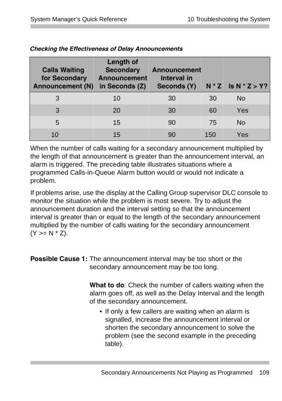
10 Troubleshooting the SystemSystem Manager’s Quick Reference
When the number of calls waiting for a secondary announcement multiplied by the length of that announcement is greater than the announcement interval, an alarm is triggered. The preceding table illustrates situations where a programmed Calls-in-Queue Alarm button would or would not indicate a problem.
If problems arise, use the display at the Calling Group supervisor DLC console to monitor the situation while the problem is most severe. Try to adjust the announcement duration and the interval setting so that the announcement interval is greater than or equal to the length of the secondary announcement multiplied by the number of calls waiting for the secondary announcement (Y >= N * Z).
Possible Cause 1: The announcement interval may be too short or the secondary announcement may be too long.
What to do: Check the number of callers waiting when the alarm goes off, as well as the Delay Interval and the length of the secondary announcement.
• If only a few callers are waiting when an alarm is signalled, increase the announcement interval or shorten the secondary announcement to solve the problem (see the second example in the preceding table).
Checking the Effectiveness of Delay Announcements
Calls Waiting for Secondary
Announcement (N)
Length of Secondary
Announcement in Seconds (Z)
Announcement Interval in
Seconds (Y) N * Z Is N * Z > Y?
3 10 30 30 No
3 20 30 60 Yes
5 15 90 75 No
10 15 90 150 Yes
Secondary Announcements Not Playing as Programmed 109
10 Troubleshooting the System System Manager’s Quick Reference
• If more than a few callers are waiting, go to Possible Cause 2.
Possible Cause 2: The primary announcement or announcements require adjustment.
What to do: Depending upon your customer needs and current Group Calling options, do one of the following to decrease the queue for the secondary announcement:
• If you are using several primary announcements, decrease the number of primary announcements.
• If the primary announcement is very short, increase its length so that customers are not immediately sent to the secondary announcement queue.
• If neither of the above conditions applies, go to Possible Cause 3.
Possible Cause 3: The secondary announcement is set to repeat, and too many callers are waiting to hear the repeated announcement.
What to do: Set the Repeat option for the secondary announcement to Off. If the secondary announcement is not set to Repeat, go to Possible Cause 4.
Possible Cause 4: Because the secondary announcement is shared by more than one Calling Group, callers are waiting too long to hear it.
What to do: Make the secondary announcement exclusive to the group whose callers are experiencing the problem. If the announcement is not shared, go to Possible Cause 5.
110 Secondary Announcements Not Playing as Programmed
10 Troubleshooting the SystemSystem Manager’s Quick Reference
Possible Cause 5: The secondary announcement device is also providing the primary announcement, so that too many callers are waiting for the secondary announcement.
What to do: Set up a separate secondary announcement. If one announcement is not serving as both primary and secondary, go to Possible Cause 6.
Possible Cause 6: The Calling Group is set to use the Prompt-Based Overflow setting that allows callers to dial # in response to a delay announcement, so that they can be connected to a Voice Mail system or other overflow receiver. The system lacks sufficient Touch-Tone Receivers (TTRs), however, to handle the callers’ requests. If you are not using this setting, go to Possible Cause 7.
What to do: Depending upon your customer needs, do one of the following to make more TTRs available:
• Shorten the length of the Primary Delay Announcement that includes the prompt to dial #.
• Decrease the number of primary delay announcement devices.
• Provide more TTRs for the Calling Group. For information about your options, consult your Avaya representative.
• Stop using the Prompt-Based Overflow setting. Modify the recording on the delay announcement accordingly.
• If none of these options cures the problem, or if the prompted requests do not seem to be the cause, go to Possible Cause 7.
Secondary Announcements Not Playing as Programmed 111
10 Troubleshooting the System System Manager’s Quick Reference
Possible Cause 7: There are not enough agents to service the call volume.
What to do: Log in additional agents or increase the number of agents in the group.
Other or Unresolved ProblemsIf you have a problem not listed in this chapter, or if after you complete the appropriate troubleshooting procedure, the problem persists, call the Avaya Helpline at 1 800 628-2888 for further assistance (consultation charges may apply). When you call the Helpline, use a copy of the System Information Sheet at the front of this guide to note a few details about your system, along with troubleshooting information.
112 Other or Unresolved Problems
A System Information
Contents
Overview. . . . . . . . . . . . . . . . . . . . . . . . . . . . . . . . . . . . . . . . . . . . . .113Line/Trunk and Extension Modules . . . . . . . . . . . . . . . . . . . . . . . . .113Auxiliary Equipment . . . . . . . . . . . . . . . . . . . . . . . . . . . . . . . . . . . . 121Features and Programming Codes. . . . . . . . . . . . . . . . . . . . . . . . . 124Applications . . . . . . . . . . . . . . . . . . . . . . . . . . . . . . . . . . . . . . . . . . 132System Capacities . . . . . . . . . . . . . . . . . . . . . . . . . . . . . . . . . . . . . 134Related Documents . . . . . . . . . . . . . . . . . . . . . . . . . . . . . . . . . . . . .143
A System Information
OverviewThe tables in this appendix provide additional information about the system components described in Chapter 1.
Line/Trunk and Extension ModulesThe system supports 17 different types of modules that vary in the types of lines/trunks that they support and the types of telephones or other equipment that can be connected to them. The following table describes the line/trunk extension modules in detail.
The names of the modules identify their capacities and capabilities. The first digit tells you the number of line/trunk jacks a module supports, while the last two digits describe the number of extension jacks it supports. Letters can follow to indicate the type of trunk it supports–that is, LS for loop-start and GS for ground-start; if the number indicates line/trunk support and no letters follow, the module supports trunks.
An example of a module name is the 408 GS/LS-ID MLX module. It provides four line/trunk jacks and eight MLX extension jacks, supports ground-start and loop-start trunks, and provides Caller ID.
Overview 113
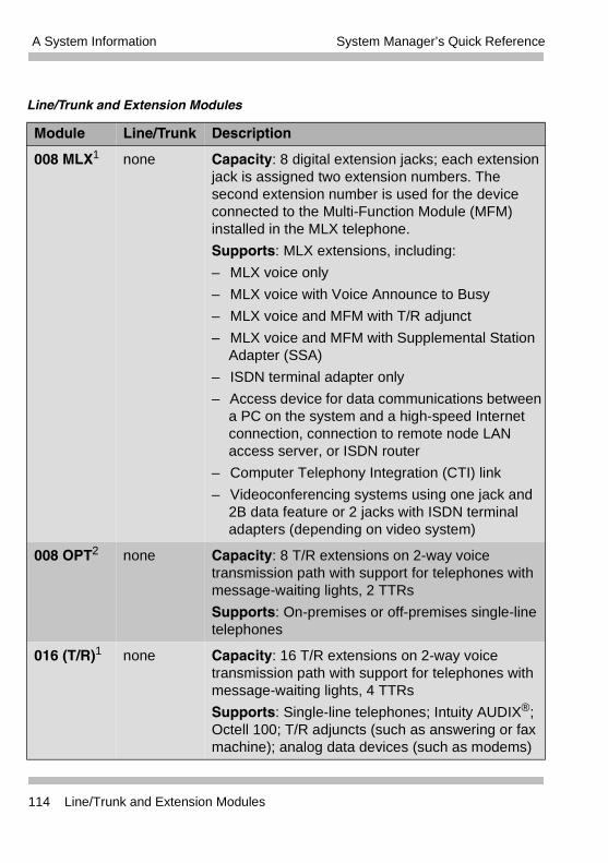
A System Information System Manager’s Quick Reference
Line/Trunk and Extension Modules
Module Line/Trunk Description
008 MLX1 none Capacity: 8 digital extension jacks; each extension jack is assigned two extension numbers. The second extension number is used for the device connected to the Multi-Function Module (MFM) installed in the MLX telephone.
Supports: MLX extensions, including:
– MLX voice only
– MLX voice with Voice Announce to Busy
– MLX voice and MFM with T/R adjunct
– MLX voice and MFM with Supplemental Station Adapter (SSA)
– ISDN terminal adapter only
– Access device for data communications between a PC on the system and a high-speed Internet connection, connection to remote node LAN access server, or ISDN router
– Computer Telephony Integration (CTI) link
– Videoconferencing systems using one jack and 2B data feature or 2 jacks with ISDN terminal adapters (depending on video system)
008 OPT2 none Capacity: 8 T/R extensions on 2-way voice transmission path with support for telephones with message-waiting lights, 2 TTRs
Supports: On-premises or off-premises single-line telephones
016 (T/R)1 none Capacity: 16 T/R extensions on 2-way voice transmission path with support for telephones with message-waiting lights, 4 TTRs
Supports: Single-line telephones; Intuity AUDIX®; Octell 100; T/R adjuncts (such as answering or fax machine); analog data devices (such as modems)
114 Line/Trunk and Extension Modules
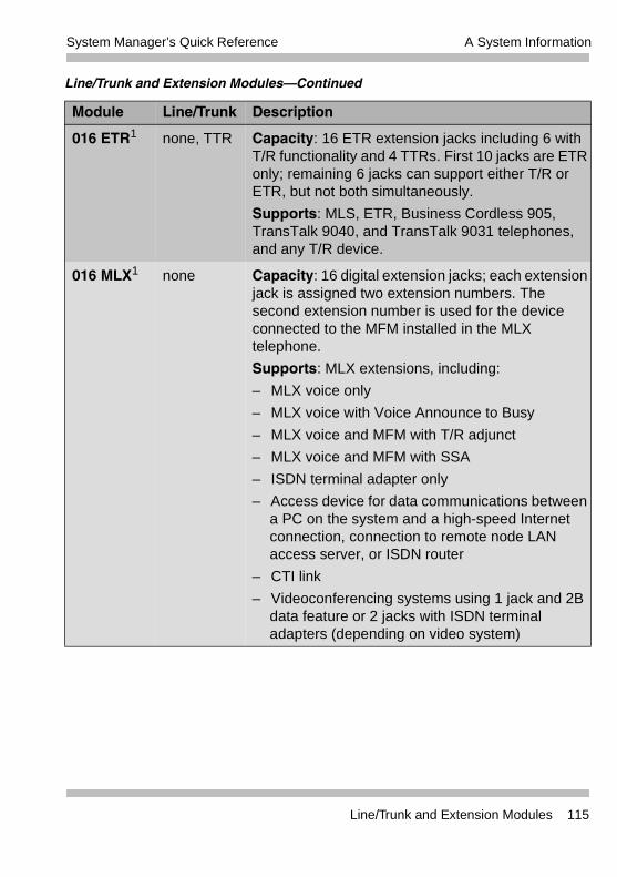
A System InformationSystem Manager’s Quick Reference
016 ETR1 none, TTR Capacity: 16 ETR extension jacks including 6 with T/R functionality and 4 TTRs. First 10 jacks are ETR only; remaining 6 jacks can support either T/R or ETR, but not both simultaneously.
Supports: MLS, ETR, Business Cordless 905, TransTalk 9040, and TransTalk 9031 telephones, and any T/R device.
016 MLX1 none Capacity: 16 digital extension jacks; each extension jack is assigned two extension numbers. The second extension number is used for the device connected to the MFM installed in the MLX telephone.
Supports: MLX extensions, including:
– MLX voice only
– MLX voice with Voice Announce to Busy
– MLX voice and MFM with T/R adjunct
– MLX voice and MFM with SSA
– ISDN terminal adapter only
– Access device for data communications between a PC on the system and a high-speed Internet connection, connection to remote node LAN access server, or ISDN router
– CTI link
– Videoconferencing systems using 1 jack and 2B data feature or 2 jacks with ISDN terminal adapters (depending on video system)
Line/Trunk and Extension Modules–Continued
Module Line/Trunk Description
Line/Trunk and Extension Modules 115
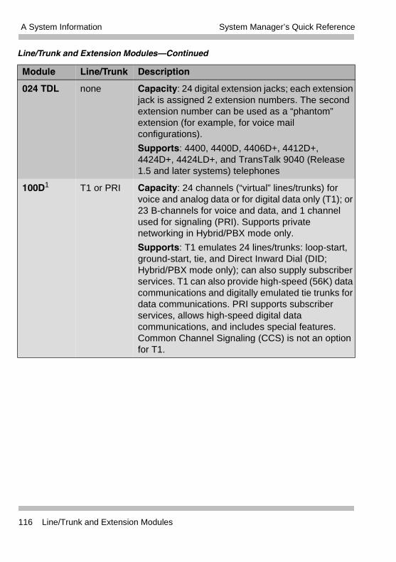
A System Information System Manager’s Quick Reference
024 TDL none Capacity: 24 digital extension jacks; each extension jack is assigned 2 extension numbers. The second extension number can be used as a “phantom” extension (for example, for voice mail configurations).
Supports: 4400, 4400D, 4406D+, 4412D+, 4424D+, 4424LD+, and TransTalk 9040 (Release 1.5 and later systems) telephones
100D1 T1 or PRI Capacity: 24 channels (“virtual” lines/trunks) for voice and analog data or for digital data only (T1); or 23 B-channels for voice and data, and 1 channel used for signaling (PRI). Supports private networking in Hybrid/PBX mode only.
Supports: T1 emulates 24 lines/trunks: loop-start, ground-start, tie, and Direct Inward Dial (DID; Hybrid/PBX mode only); can also supply subscriber services. T1 can also provide high-speed (56K) data communications and digitally emulated tie trunks for data communications. PRI supports subscriber services, allows high-speed digital data communications, and includes special features. Common Channel Signaling (CCS) is not an option for T1.
Line/Trunk and Extension Modules–Continued
Module Line/Trunk Description
116 Line/Trunk and Extension Modules
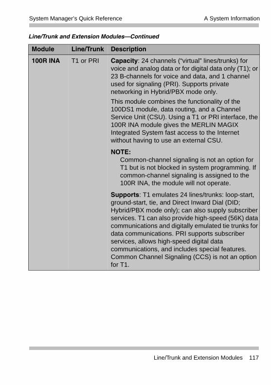
A System InformationSystem Manager’s Quick Reference
100R INA T1 or PRI Capacity: 24 channels (“virtual” lines/trunks) for voice and analog data or for digital data only (T1); or 23 B-channels for voice and data, and 1 channel used for signaling (PRI). Supports private networking in Hybrid/PBX mode only.
This module combines the functionality of the 100DS1 module, data routing, and a Channel Service Unit (CSU). Using a T1 or PRI interface, the 100R INA module gives the MERLIN MAGIX Integrated System fast access to the Internet without having to use an external CSU.
NOTE:Common-channel signaling is not an option for T1 but is not blocked in system programming. If common-channel signaling is assigned to the 100R INA, the module will not operate.
Supports: T1 emulates 24 lines/trunks: loop-start, ground-start, tie, and Direct Inward Dial (DID; Hybrid/PBX mode only); can also supply subscriber services. T1 can also provide high-speed (56K) data communications and digitally emulated tie trunks for data communications. PRI supports subscriber services, allows high-speed digital data communications, and includes special features. Common Channel Signaling (CCS) is not an option for T1.
Line/Trunk and Extension Modules–Continued
Module Line/Trunk Description
Line/Trunk and Extension Modules 117
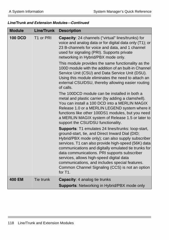
A System Information System Manager’s Quick Reference
100 DCD T1 or PRI Capacity: 24 channels (“virtual” lines/trunks) for voice and analog data or for digital data only (T1); or 23 B-channels for voice and data, and 1 channel used for signaling (PRI). Supports private networking in Hybrid/PBX mode only.
This module provides the same functionality as the 100D module with the addition of an built-in Channel Service Unit (CSU) and Data Service Unit (DSU). Using this module eliminates the need to attach an external CSU/DSU, thereby allowing easier routing of calls.
The 100DCD module can be installed in both a metal and plastic carrier (by adding a clamshell). You can install a 100 DCD into a MERLIN MAGIX Release 1.0 or a MERLIN LEGEND system where it functions like other 100DS1 modules, but you need a MERLIN MAGIX system of Release 1.5 or later to support the CSU/DSU functionality.
Supports: T1 emulates 24 lines/trunks: loop-start, ground-start, tie, and Direct Inward Dial (DID; Hybrid/PBX mode only); can also supply subscriber services. T1 can also provide high-speed (56K) data communications and digitally emulated tie trunks for data communications. PRI supports subscriber services, allows high-speed digital data communications, and includes special features. Common Channel Signaling (CCS) is not an option for T1.
400 EM Tie trunk Capacity: 4 analog tie trunks
Supports: Networking in Hybrid/PBX mode only
Line/Trunk and Extension Modules–Continued
Module Line/Trunk Description
118 Line/Trunk and Extension Modules
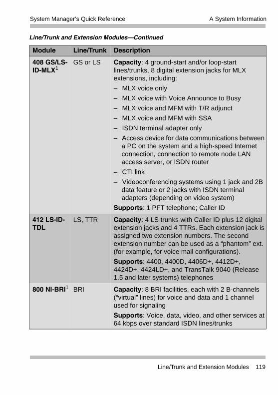
A System InformationSystem Manager’s Quick Reference
408 GS/LS-ID-MLX1
GS or LS Capacity: 4 ground-start and/or loop-start lines/trunks, 8 digital extension jacks for MLX extensions, including:
– MLX voice only
– MLX voice with Voice Announce to Busy
– MLX voice and MFM with T/R adjunct
– MLX voice and MFM with SSA
– ISDN terminal adapter only
– Access device for data communications between a PC on the system and a high-speed Internet connection, connection to remote node LAN access server, or ISDN router
– CTI link
– Videoconferencing systems using 1 jack and 2B data feature or 2 jacks with ISDN terminal adapters (depending on video system)
Supports: 1 PFT telephone; Caller ID
412 LS-ID-TDL
LS, TTR Capacity: 4 LS trunks with Caller ID plus 12 digital extension jacks and 4 TTRs. Each extension jack is assigned two extension numbers. The second extension number can be used as a “phantom” ext. (for example, for voice mail configurations).
Supports: 4400, 4400D, 4406D+, 4412D+, 4424D+, 4424LD+, and TransTalk 9040 (Release 1.5 and later systems) telephones
800 NI-BRI1 BRI Capacity: 8 BRI facilities, each with 2 B-channels (“virtual” lines) for voice and data and 1 channel used for signaling
Supports: Voice, data, video, and other services at 64 kbps over standard ISDN lines/trunks
Line/Trunk and Extension Modules–Continued
Module Line/Trunk Description
Line/Trunk and Extension Modules 119
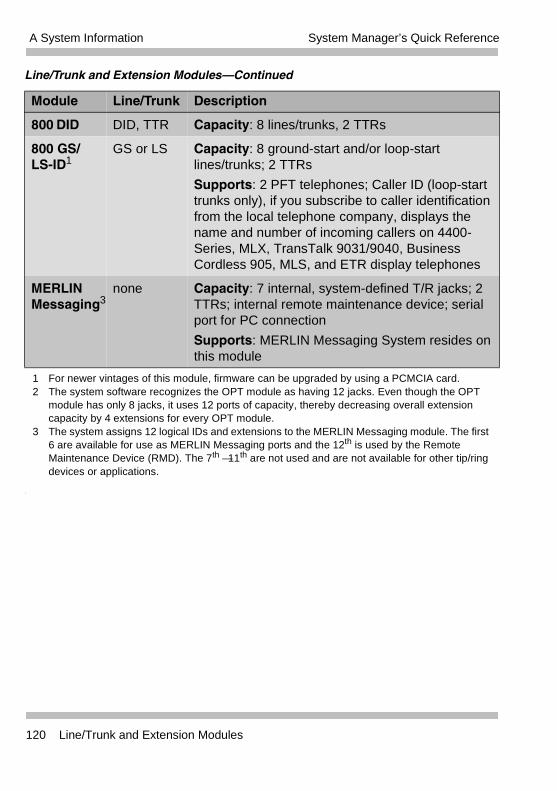
A System Information System Manager’s Quick Reference
800 DID DID, TTR Capacity: 8 lines/trunks, 2 TTRs
800 GS/ LS-ID1
GS or LS Capacity: 8 ground-start and/or loop-start lines/trunks; 2 TTRs
Supports: 2 PFT telephones; Caller ID (loop-start trunks only), if you subscribe to caller identification from the local telephone company, displays the name and number of incoming callers on 4400- Series, MLX, TransTalk 9031/9040, Business Cordless 905, MLS, and ETR display telephones
MERLIN Messaging3
none Capacity: 7 internal, system-defined T/R jacks; 2 TTRs; internal remote maintenance device; serial port for PC connection
Supports: MERLIN Messaging System resides on this module
1 For newer vintages of this module, firmware can be upgraded by using a PCMCIA card.2 The system software recognizes the OPT module as having 12 jacks. Even though the OPT
module has only 8 jacks, it uses 12 ports of capacity, thereby decreasing overall extension capacity by 4 extensions for every OPT module.
3 The system assigns 12 logical IDs and extensions to the MERLIN Messaging module. The first 6 are available for use as MERLIN Messaging ports and the 12th is used by the Remote Maintenance Device (RMD). The 7th —11th are not used and are not available for other tip/ring devices or applications.
Line/Trunk and Extension Modules–Continued
Module Line/Trunk Description
120 Line/Trunk and Extension Modules
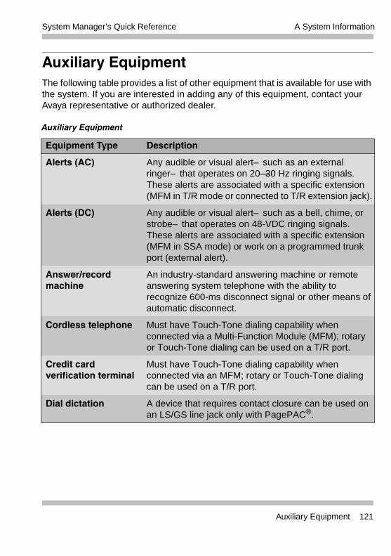
A System InformationSystem Manager’s Quick Reference
Auxiliary EquipmentThe following table provides a list of other equipment that is available for use with the system. If you are interested in adding any of this equipment, contact your Avaya representative or authorized dealer.
Auxiliary Equipment
Equipment Type Description
Alerts (AC) Any audible or visual alert–such as an external ringer–that operates on 20—30 Hz ringing signals. These alerts are associated with a specific extension (MFM in T/R mode or connected to T/R extension jack).
Alerts (DC) Any audible or visual alert–such as a bell, chime, or strobe–that operates on 48-VDC ringing signals. These alerts are associated with a specific extension (MFM in SSA mode) or work on a programmed trunk port (external alert).
Answer/record machine
An industry-standard answering machine or remote answering system telephone with the ability to recognize 600-ms disconnect signal or other means of automatic disconnect.
Cordless telephone Must have Touch-Tone dialing capability when connected via a Multi-Function Module (MFM); rotary or Touch-Tone dialing can be used on a T/R port.
Credit card verification terminal
Must have Touch-Tone dialing capability when connected via an MFM; rotary or Touch-Tone dialing can be used on a T/R port.
Dial dictation A device that requires contact closure can be used on an LS/GS line jack only with PagePAC®.
Auxiliary Equipment 121
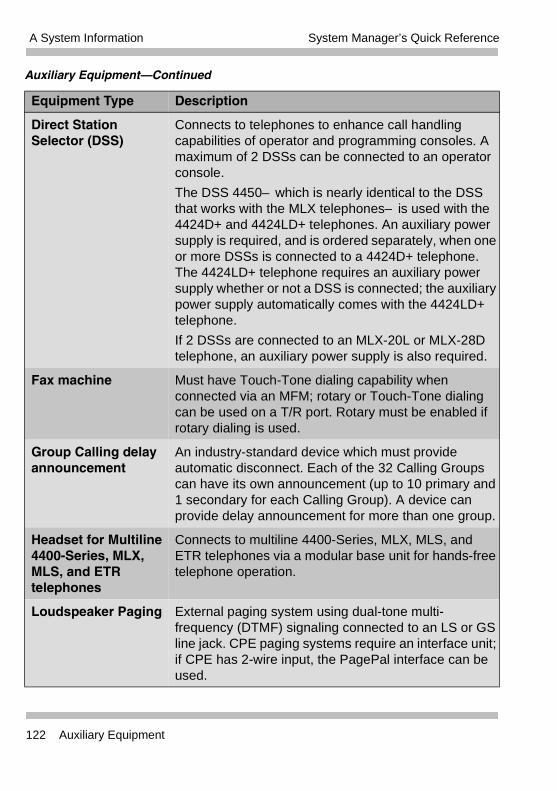
A System Information System Manager’s Quick Reference
Direct Station Selector (DSS)
Connects to telephones to enhance call handling capabilities of operator and programming consoles. A maximum of 2 DSSs can be connected to an operator console.
The DSS 4450–which is nearly identical to the DSS that works with the MLX telephones–is used with the 4424D+ and 4424LD+ telephones. An auxiliary power supply is required, and is ordered separately, when one or more DSSs is connected to a 4424D+ telephone. The 4424LD+ telephone requires an auxiliary power supply whether or not a DSS is connected; the auxiliary power supply automatically comes with the 4424LD+ telephone.
If 2 DSSs are connected to an MLX-20L or MLX-28D telephone, an auxiliary power supply is also required.
Fax machine Must have Touch-Tone dialing capability when connected via an MFM; rotary or Touch-Tone dialing can be used on a T/R port. Rotary must be enabled if rotary dialing is used.
Group Calling delay announcement
An industry-standard device which must provide automatic disconnect. Each of the 32 Calling Groups can have its own announcement (up to 10 primary and 1 secondary for each Calling Group). A device can provide delay announcement for more than one group.
Headset for Multiline 4400-Series, MLX, MLS, and ETR telephones
Connects to multiline 4400-Series, MLX, MLS, and ETR telephones via a modular base unit for hands-free telephone operation.
Loudspeaker Paging External paging system using dual-tone multi- frequency (DTMF) signaling connected to an LS or GS line jack. CPE paging systems require an interface unit; if CPE has 2-wire input, the PagePal interface can be used.
Auxiliary Equipment–Continued
Equipment Type Description
122 Auxiliary Equipment
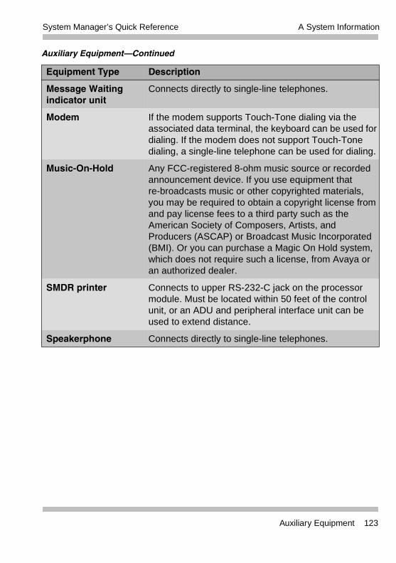
A System InformationSystem Manager’s Quick Reference
Message Waiting indicator unit
Connects directly to single-line telephones.
Modem If the modem supports Touch-Tone dialing via the associated data terminal, the keyboard can be used for dialing. If the modem does not support Touch-Tone dialing, a single-line telephone can be used for dialing.
Music-On-Hold Any FCC-registered 8-ohm music source or recorded announcement device. If you use equipment that re-broadcasts music or other copyrighted materials, you may be required to obtain a copyright license from and pay license fees to a third party such as the American Society of Composers, Artists, and Producers (ASCAP) or Broadcast Music Incorporated (BMI). Or you can purchase a Magic On Hold system, which does not require such a license, from Avaya or an authorized dealer.
SMDR printer Connects to upper RS-232-C jack on the processor module. Must be located within 50 feet of the control unit, or an ADU and peripheral interface unit can be used to extend distance.
Speakerphone Connects directly to single-line telephones.
Auxiliary Equipment–Continued
Equipment Type Description
Auxiliary Equipment 123
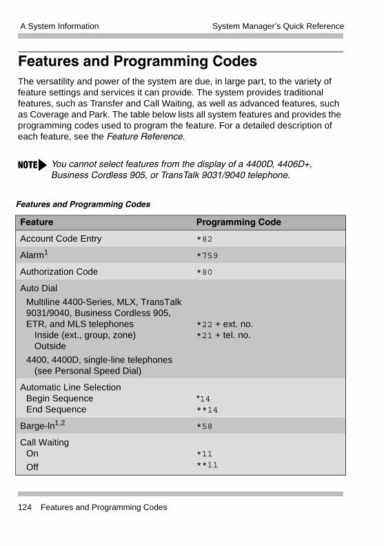
A System Information System Manager’s Quick Reference
Features and Programming CodesThe versatility and power of the system are due, in large part, to the variety of feature settings and services it can provide. The system provides traditional features, such as Transfer and Call Waiting, as well as advanced features, such as Coverage and Park. The table below lists all system features and provides the programming codes used to program the feature. For a detailed description of each feature, see the Feature Reference.
You cannot select features from the display of a 4400D, 4406D+, Business Cordless 905, or TransTalk 9031/9040 telephone.
Features and Programming Codes
Feature Programming Code
Account Code Entry *82
Alarm1 *759
Authorization Code *80
Auto Dial
Multiline 4400-Series, MLX, TransTalk 9031/9040, Business Cordless 905, ETR, and MLS telephones
Inside (ext., group, zone)Outside
4400, 4400D, single-line telephones(see Personal Speed Dial)
*22 + ext. no.*21 + tel. no.
Automatic Line SelectionBegin SequenceEnd Sequence
*14**14
Barge-ln1,2 *58
Call WaitingOn
Off
*11 **11
124 Features and Programming Codes
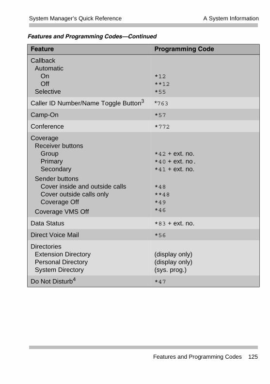
A System InformationSystem Manager’s Quick Reference
CallbackAutomatic
OnOff
Selective
*12**12*55
Caller ID Number/Name Toggle Button3 *763
Camp-On *57
Conference *772
CoverageReceiver buttons
GroupPrimarySecondary
Sender buttonsCover inside and outside callsCover outside calls onlyCoverage Off
Coverage VMS Off
*42 + ext. no.*40 + ext. no.*41 + ext. no.
*48**48*49*46
Data Status *83 + ext. no.
Direct Voice Mail *56
Directories Extension Directory Personal Directory System Directory
(display only)(display only)(sys. prog.)
Do Not Disturb4 *47
Features and Programming Codes–Continued
Feature Programming Code
Features and Programming Codes 125
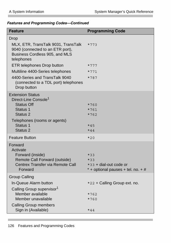
A System Information System Manager’s Quick Reference
Drop
MLX, ETR, TransTalk 9031, TransTalk 9040 (connected to an ETR port), Business Cordless 905, and MLS telephones
ETR telephones Drop button
Multiline 4400-Series telephones
4400-Series and TransTalk 9040 (connected to a TDL port) telephonesDrop button
*773
*777
*771
*787
Extension StatusDirect-Line Console1
Status OffStatus 1Status 2
Telephones (rooms or agents) Status 1 Status 2
*760*761*762
*45*44
Feature Button *20
ForwardActivate
Forward (inside) Remote Call Forward (outside)Centrex Transfer via Remote Call
Forward
*33*33 *33 + dial-out code or* + optional pauses + tel. no. + #
Group Calling
ln-Queue Alarm button
Calling Group supervisor1
Member availableMember unavailable
Calling Group membersSign in (Available)
*22 + Calling Group ext. no.
*762*760
*44
Features and Programming Codes–Continued
Feature Programming Code
126 Features and Programming Codes
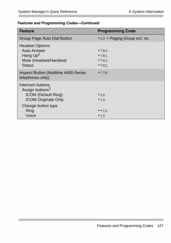
A System InformationSystem Manager’s Quick Reference
Group Page Auto Dial Button *22 + Paging Group ext. no.
Headset OptionsAuto Answer Hang Up2
Mute (Headset/Handset) Status
*780*781*783*782
Inspect Button (Multiline 4400-Series telephones only)
*778
Intercom buttonsAssign buttons2
ICOM (Default Ring) ICOM Originate Only
Change button type Ring Voice
*16*18
**19*19
Features and Programming Codes–Continued
Feature Programming Code
Features and Programming Codes 127
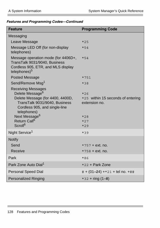
A System Information System Manager’s Quick Reference
Messaging
Leave Message
Message LED Off (for non-displaytelephones)
Message operation mode (for 4406D+,TransTalk 9031/9040, Business Cordless 905, ETR, and MLS display telephones)5
Posted Message
Send/Remove Msg1
Receiving Messages Delete Message6
Delete Message (for 4400, 4400D, TransTalk 9031/9040, Business Cordless 905, and single-line telephones)
Next Message6
Return Call6
Scroll6
*25
*54
*54
*751
*38
*26*25 within 15 seconds of entering extension no.
*28*27*29
Night Service1 *39
Notify
Send
Receive
*757 + ext. no.
*758 + ext. no.
Park *86
Park Zone Auto Dial1 *22 + Park Zone
Personal Speed Dial # + (01—24) +*21 + tel no. +##
Personalized Ringing *32 + ring (1—8)
Features and Programming Codes–Continued
Feature Programming Code
128 Features and Programming Codes
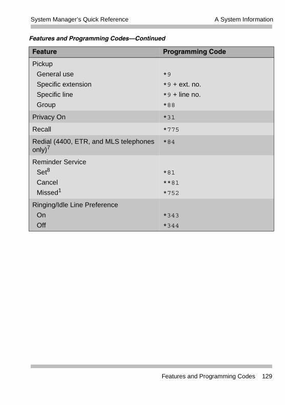
A System InformationSystem Manager’s Quick Reference
Pickup
General use
Specific extension
Specific line
Group
*9
*9 + ext. no.
*9 + line no.
*88
Privacy On *31
Recall *775
Redial (4400, ETR, and MLS telephones only)7
*84
Reminder Service
Set8
Cancel
Missed1
*81
**81
*752
Ringing/Idle Line Preference
On
Off
*343
*344
Features and Programming Codes–Continued
Feature Programming Code
Features and Programming Codes 129
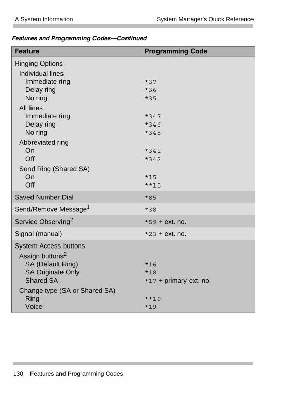
A System Information System Manager’s Quick Reference
Ringing Options
Individual lines Immediate ring Delay ring No ring
All lines Immediate ring Delay ring No ring
Abbreviated ring On Off
Send Ring (Shared SA) On Off
*37*36*35
*347*346*345
*341*342
*15**15
Saved Number Dial *85
Send/Remove Message1 *38
Service Observing2 *59 + ext. no.
Signal (manual) *23 + ext. no.
System Access buttons
Assign buttons2
SA (Default Ring) SA Originate Only Shared SA
Change type (SA or Shared SA) Ring Voice
*16*18*17 + primary ext. no.
**19*19
Features and Programming Codes–Continued
Feature Programming Code
130 Features and Programming Codes
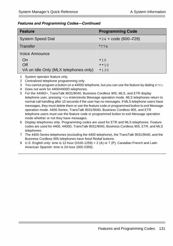
A System InformationSystem Manager’s Quick Reference
System Speed Dial *24 + code (600—729)
Transfer *774
Voice Announce
On Off VA on Idle Only (MLX telephones only)
*10**10 *130
1 System operator feature only.2 Centralized telephone programming only.3 You cannot program a button on a 4400D telephone, but you can use the feature by dialing #763.4 Does not work for 4400/4400D telephones.5 For the 4406D+, TransTalk 9031/9040, Business Cordless 905, MLS, and ETR display
telephone user, pressing *54 enters/exits Message operation mode. MLS telephones return to normal call handling after 15 seconds if the user has no messages. If MLS telephone users have messages, they must delete them or use the feature code or programmed button to exit Message operation mode. 4400-Series, TransTalk 9031/9040, Business Cordless 905, and ETR telephone users must use the feature code or programmed button to exit Message operation mode whether or not they have messages.
6 Display telephones only. Programming codes are used for ETR and MLS telephones. Feature codes are used for 4400, 4400D, TransTalk 9031/9040, Business Cordless 905, ETR, and MLS telephones.
7 The 4400-Series telephones (excluding the 4400 telephone), the TransTalk 9031/9040, and the Business Cordless 905 telephones have fixed Redial buttons.
8 U.S. English only: time is 12-hour (0100-1259) + 2 (A) or 7 (P); Canadian French and Latin American Spanish: time is 24-hour (000-2359).
Features and Programming Codes–Continued
Feature Programming Code
Features and Programming Codes 131
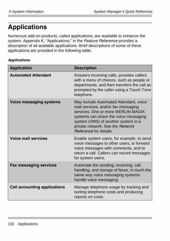
A System Information System Manager’s Quick Reference
ApplicationsNumerous add-on products, called applications, are available to enhance the system. Appendix K, “Applications,” in the Feature Reference provides a description of all available applications. Brief descriptions of some of these applications are provided in the following table.
Applications
Application Description
Automated Attendant Answers incoming calls, provides callers with a menu of choices, such as people or departments, and then transfers the call as prompted by the caller using a Touch-Tone telephone.
Voice messaging systems May include Automated Attendant, voice mail services, and/or fax messaging services. One or more MERLIN MAGIX systems can share the voice messaging system (VMS) of another system in a private network. See the Network Reference for details.
Voice mail services Enable system users, for example, to send voice messages to other users, to forward voice messages with comments, and to return a call. Callers can record messages for system users.
Fax messaging services Automate the sending, receiving, call handling, and storage of faxes, in much the same way voice messaging systems handle voice messaging.
Call accounting applications Manage telephone usage by tracking and sorting telephone costs and producing reports on costs.
132 Applications
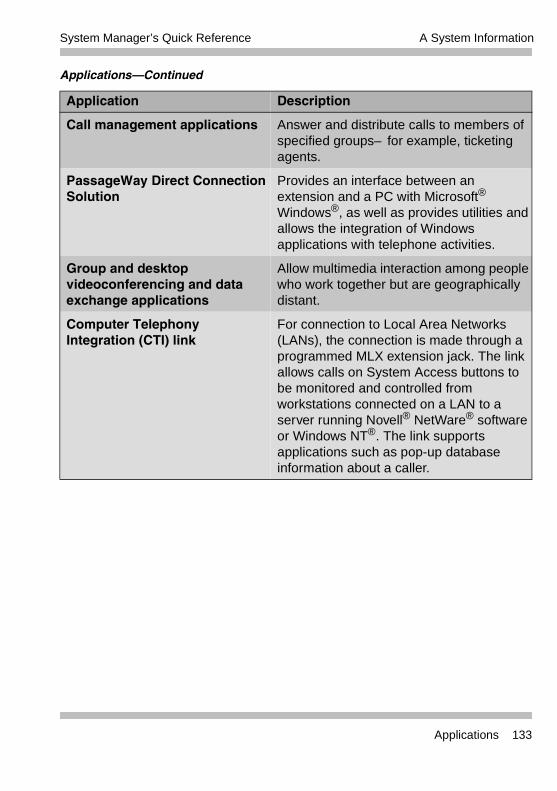
A System InformationSystem Manager’s Quick Reference
Call management applications Answer and distribute calls to members of specified groups–for example, ticketing agents.
PassageWay Direct Connection Solution
Provides an interface between an extension and a PC with Microsoft® Windows®, as well as provides utilities and allows the integration of Windows applications with telephone activities.
Group and desktop videoconferencing and data exchange applications
Allow multimedia interaction among people who work together but are geographically distant.
Computer Telephony Integration (CTI) link
For connection to Local Area Networks (LANs), the connection is made through a programmed MLX extension jack. The link allows calls on System Access buttons to be monitored and controlled from workstations connected on a LAN to a server running Novell® NetWare® software or Windows NT®. The link supports applications such as pop-up database information about a caller.
Applications–Continued
Application Description
Applications 133
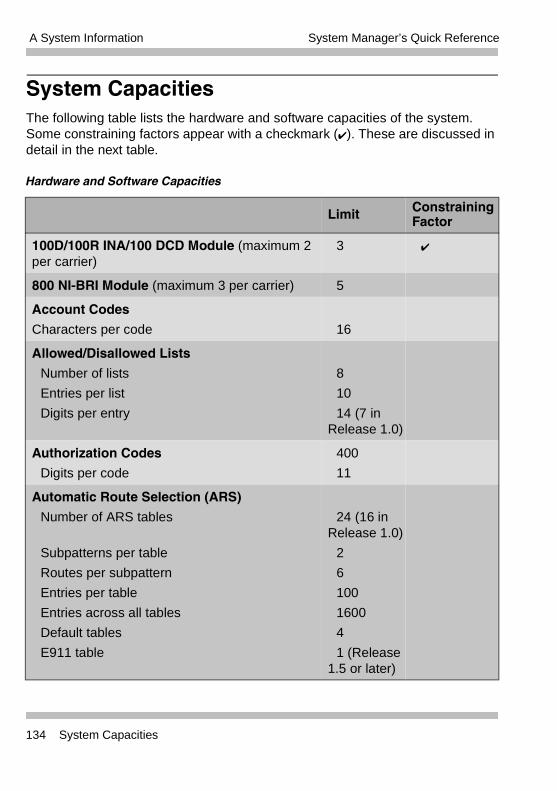
A System Information System Manager’s Quick Reference
System CapacitiesThe following table lists the hardware and software capacities of the system. Some constraining factors appear with a checkmark (�). These are discussed in detail in the next table.
Hardware and Software Capacities
Limit ConstrainingFactor
100D/100R INA/100 DCD Module (maximum 2 per carrier)
3 �
800 NI-BRI Module (maximum 3 per carrier) 5
Account Codes
Characters per code 16
Allowed/Disallowed Lists
Number of lists
Entries per list
Digits per entry
8
10
14 (7 in Release 1.0)
Authorization Codes
Digits per code
400
11
Automatic Route Selection (ARS)
Number of ARS tables
Subpatterns per table
Routes per subpattern
Entries per table
Entries across all tables
Default tables
E911 table
24 (16 in Release 1.0)
2
6
100
1600
4
1 (Release 1.5 or later)
134 System Capacities
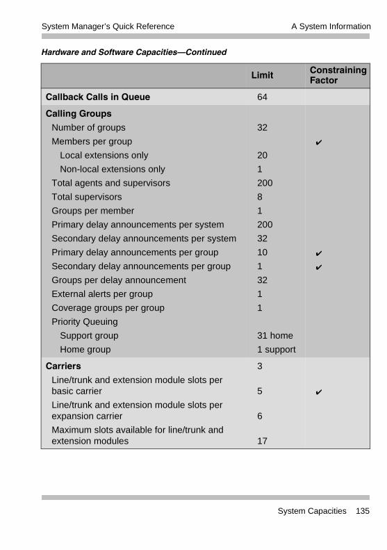
A System InformationSystem Manager’s Quick Reference
Callback Calls in Queue 64
Calling Groups
Number of groups
Members per group
Local extensions only
Non-local extensions only
Total agents and supervisors
Total supervisors
Groups per member
Primary delay announcements per system
Secondary delay announcements per system
Primary delay announcements per group
Secondary delay announcements per group
Groups per delay announcement
External alerts per group
Coverage groups per group
Priority Queuing
Support group
Home group
32
20
1
200
8
1
200
32
10
1
32
1
1
31 home
1 support
�
�
�
Carriers
Line/trunk and extension module slots per basic carrier
Line/trunk and extension module slots perexpansion carrier
Maximum slots available for line/trunk and extension modules
3
5
6
17
�
Hardware and Software Capacities–Continued
Limit ConstrainingFactor
System Capacities 135
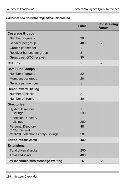
A System Information System Manager’s Quick Reference
Coverage Groups
Number of groups
Senders per group
Groups per sender
Receiver buttons per group
Groups per QCC receiver
30
400
1
8
30
�
CTI Link 1 �
Data Hunt Groups
Number of groups
Members per group
Groups per member
32
20
1
Direct Inward Dialing
Number of blocks
Number of trunks
2
80
Directories
System DirectoryListings
Extension DirectoryListings
Personal Directory (4424LD+ and MLX-20L telephones only) Listings
1130
1200
48
50
Endpoints (devices) 400
Extensions
Total physical jacks
Total endpoints
200
400
Fax machines with Message Waiting 16 �
Hardware and Software Capacities–Continued
Limit ConstrainingFactor
136 System Capacities
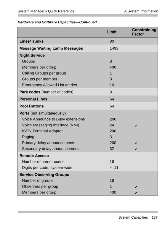
A System InformationSystem Manager’s Quick Reference
Lines/Trunks 80
Message Waiting Lamp Messages 1499
Night Service
Groups
Members per group
Calling Groups per group
Groups per member
Emergency Allowed List entries
8
400
1
8
10
Park codes (number of codes) 8
Personal Lines 64
Pool Buttons 64
Ports (not simultaneously)
Voice Announce to Busy extensions
Voice Messaging Interface (VMI)
ISDN Terminal Adapter
Paging
Primary delay announcements
Secondary delay announcements
200
24
200
3
200
32
�
�
�
Remote Access
Number of barrier codes
Digits per code, system-wide
16
4—11
Service Observing Groups
Number of groups
Observers per group
Members per group
16
1
400
�
�
Hardware and Software Capacities–Continued
Limit ConstrainingFactor
System Capacities 137
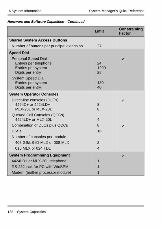
A System Information System Manager’s Quick Reference
Shared System Access Buttons
Number of buttons per principal extension 27
Speed Dial
Personal Speed DialEntries per telephoneEntries per systemDigits per entry
System Speed DialEntries per systemDigits per entry
24120028
13040
�
System Operator Consoles
Direct-line consoles (DLCs)4424D+ or 4424LD+MLX-20L or MLX-28D
Queued Call Consoles (QCCs)4424LD+ or MLX-20L
Combination of DLCs plus QCCs
DSSs
Number of consoles per module
408 GS/LS-ID-MLX or 008 MLX
016 MLX or 024 TDL
88
4
8
16
2
4
�
�
System Programming Equipment
4424LD+ or MLX-20L telephone
RS-232 jack for PC with WinSPM
Modem (built-in processor module)
1
1
1
�
Hardware and Software Capacities–Continued
Limit ConstrainingFactor
138 System Capacities
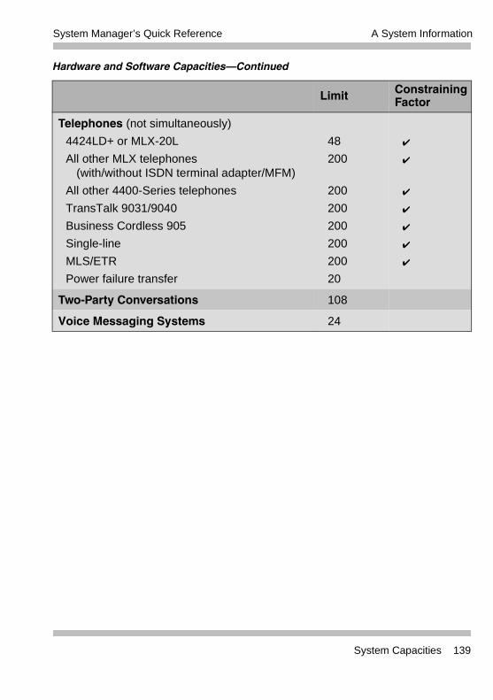
A System InformationSystem Manager’s Quick Reference
Telephones (not simultaneously)
4424LD+ or MLX-20L
All other MLX telephones(with/without ISDN terminal adapter/MFM)
All other 4400-Series telephones
TransTalk 9031/9040
Business Cordless 905
Single-line
MLS/ETR
Power failure transfer
48
200
200
200
200
200
200
20
�
�
�
�
�
�
�
Two-Party Conversations 108
Voice Messaging Systems 24
Hardware and Software Capacities–Continued
Limit ConstrainingFactor
System Capacities 139
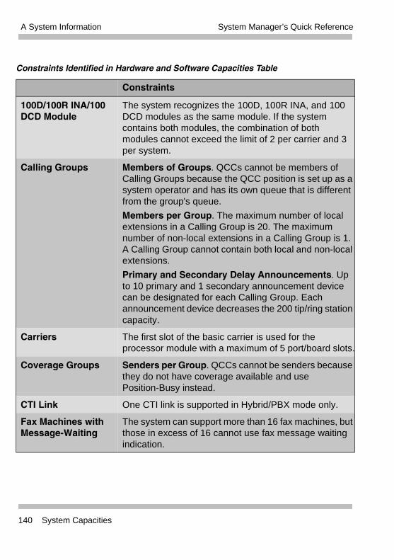
A System Information System Manager’s Quick Reference
Constraints Identified in Hardware and Software Capacities Table
Constraints
100D/100R INA/100 DCD Module
The system recognizes the 100D, 100R INA, and 100 DCD modules as the same module. If the system contains both modules, the combination of both modules cannot exceed the limit of 2 per carrier and 3 per system.
Calling Groups Members of Groups. QCCs cannot be members of Calling Groups because the QCC position is set up as a system operator and has its own queue that is different from the group's queue.
Members per Group. The maximum number of local extensions in a Calling Group is 20. The maximum number of non-local extensions in a Calling Group is 1. A Calling Group cannot contain both local and non-local extensions.
Primary and Secondary Delay Announcements. Up to 10 primary and 1 secondary announcement device can be designated for each Calling Group. Each announcement device decreases the 200 tip/ring station capacity.
Carriers The first slot of the basic carrier is used for the processor module with a maximum of 5 port/board slots.
Coverage Groups Senders per Group. QCCs cannot be senders because they do not have coverage available and use Position-Busy instead.
CTI Link One CTI link is supported in Hybrid/PBX mode only.
Fax Machines with Message-Waiting
The system can support more than 16 fax machines, but those in excess of 16 cannot use fax message waiting indication.
140 System Capacities
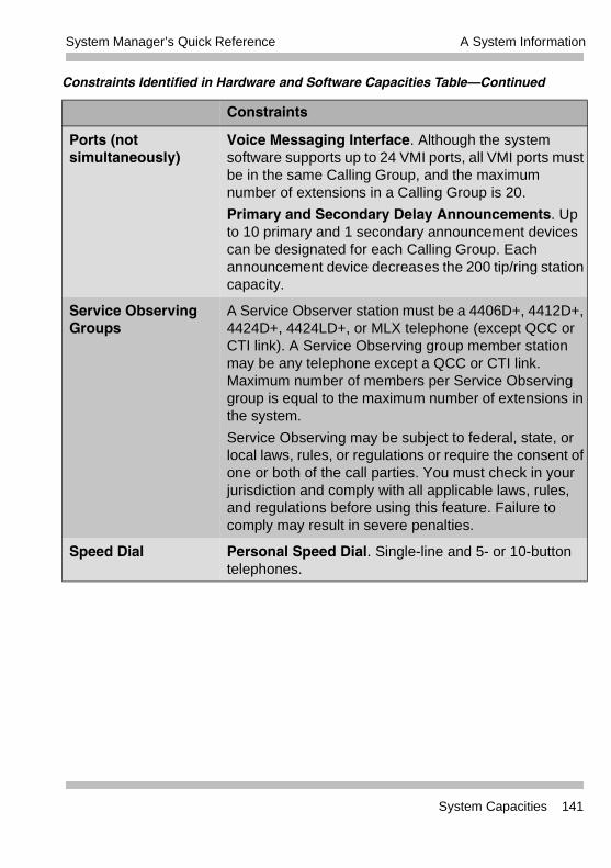
A System InformationSystem Manager’s Quick Reference
Ports (not simultaneously)
Voice Messaging Interface. Although the system software supports up to 24 VMI ports, all VMI ports must be in the same Calling Group, and the maximum number of extensions in a Calling Group is 20.
Primary and Secondary Delay Announcements. Up to 10 primary and 1 secondary announcement devices can be designated for each Calling Group. Each announcement device decreases the 200 tip/ring station capacity.
Service Observing Groups
A Service Observer station must be a 4406D+, 4412D+, 4424D+, 4424LD+, or MLX telephone (except QCC or CTI link). A Service Observing group member station may be any telephone except a QCC or CTI link. Maximum number of members per Service Observing group is equal to the maximum number of extensions in the system.
Service Observing may be subject to federal, state, or local laws, rules, or regulations or require the consent of one or both of the call parties. You must check in your jurisdiction and comply with all applicable laws, rules, and regulations before using this feature. Failure to comply may result in severe penalties.
Speed Dial Personal Speed Dial. Single-line and 5- or 10-button telephones.
Constraints Identified in Hardware and Software Capacities Table–Continued
Constraints
System Capacities 141
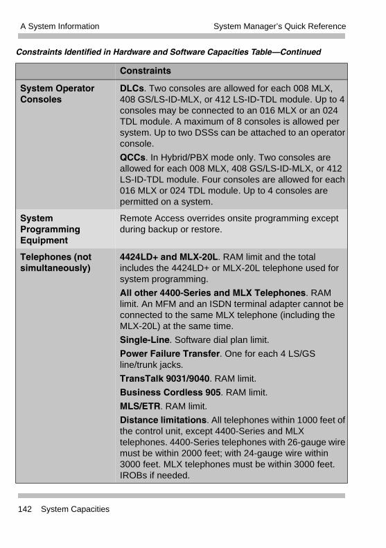
A System Information System Manager’s Quick Reference
System Operator Consoles
DLCs. Two consoles are allowed for each 008 MLX, 408 GS/LS-ID-MLX, or 412 LS-ID-TDL module. Up to 4 consoles may be connected to an 016 MLX or an 024 TDL module. A maximum of 8 consoles is allowed per system. Up to two DSSs can be attached to an operator console.
QCCs. In Hybrid/PBX mode only. Two consoles are allowed for each 008 MLX, 408 GS/LS-ID-MLX, or 412 LS-ID-TDL module. Four consoles are allowed for each 016 MLX or 024 TDL module. Up to 4 consoles are permitted on a system.
System Programming Equipment
Remote Access overrides onsite programming except during backup or restore.
Telephones (not simultaneously)
4424LD+ and MLX-20L. RAM limit and the total includes the 4424LD+ or MLX-20L telephone used for system programming.
All other 4400-Series and MLX Telephones. RAM limit. An MFM and an ISDN terminal adapter cannot be connected to the same MLX telephone (including the MLX-20L) at the same time.
Single-Line. Software dial plan limit.
Power Failure Transfer. One for each 4 LS/GS line/trunk jacks.
TransTalk 9031/9040. RAM limit.
Business Cordless 905. RAM limit.
MLS/ETR. RAM limit.
Distance limitations. All telephones within 1000 feet of the control unit, except 4400-Series and MLX telephones. 4400-Series telephones with 26-gauge wire must be within 2000 feet; with 24-gauge wire within 3000 feet. MLX telephones must be within 3000 feet. IROBs if needed.
Constraints Identified in Hardware and Software Capacities Table–Continued
Constraints
142 System Capacities
A System InformationSystem Manager’s Quick Reference
Related DocumentsThe documents listed in the following table are part of the MERLIN MAGIX documentation set. Within the continental United States, contact the Avaya Publications Center by calling 1 800 457-1235.
Document No. Title
System Documents:
555-720-100 Customer Documentation Package:
Consists of paper versions of the System Manager’s Quick Reference and the Feature Reference
555-720-110 Feature Reference
555-720-112 System Planning
555-720-113 System Planning Forms
555-720-119 System Manager’s Quick Reference
555-661-150 Network Reference
555-720-800 Customer Reference CD-ROM:
Consists of the System Manager’s Quick Reference, and the Feature Reference
Telephone User Support:
555-710-123(U.S. English)
4400/4400D Telephone User’s Guide
555-710-123FRC (Canadian French)
4400/4400D Telephone User’s Guide
555-710-127 (U.S. English)
4406D+, 4412D+, 4424D+, and 4424LD+ Telephone User’s Guide
555-710-127FRC (Canadian French)
4406D+, 4412D+, 4424D+, and 4424LD+ Telephone User’s Guide
555-660-122 MLX Display Telephone User’s Guide
Related Documents 143
A System Information System Manager’s Quick Reference
555-630-150 MLX- 5D, MLX-10D and MLX-10DP Display Telephone Tray Cards (5 cards)
555-630-152 MLX-28D and MLX-20L Telephone Tray Cards (5 cards)
555-660-124 MLX-5® and MLX-10® Nondisplay Telephone User’s Guide
555-630-151 MLX-5 and MLX-10 Nondisplay Telephone Tray Cards (6 cards)
555-630-155 MLX-16DP Display Telephone Tray Cards (5 cards)
555-670-151 MLS and ETR Telephone Tray Cards
555-670-152 MLS and ETR Telephone Tray Cards (16 cards)
555-660-126 Single-Line Telephones User’s Guide
555-660-138 MDC and MDW Telephones User's Guide
System Operator Support:
555-710-134 Digital Direct Line Console Operator’s Guide
555-710-136 Digital Queued Call Console Operator’s Guide
Miscellaneous User Support:
555-661-130 Calling Group Supervisor and Service Observer User Guide
555-650-105 Data and Video Reference
555-661-140 Installation, SPM, Maintenance and Troubleshooting
555-720-140 Installation, Programming Basics, Maintenance and Troubleshooting
555-720-116 Pocket Reference
Toll Fraud Security:
555-025-600 BCS Products Security Handbook
Document No. Title
144 Related Documents
A System InformationSystem Manager’s Quick Reference
How to Comment on This GuideWe welcome your comments, both positive and negative. Please use the feedback form on the next page to let us know how we can continue to serve you. If the feedback form is missing, write directly to:
Documentation ManagerAvaya Inc.150 Allen Road, Room C-19Liberty Corner, New Jersey 07938
How to Comment on This Guide 145
A System Information System Manager’s Quick Reference
146 Related Documents
Index GL
Numerics008 MLX module, 114008 OPT module, 114016 (T/R) module, 114016 ETR module, 115
programming T/R ports, 23016 MLX module, 115016 module
programming T/R ports, 19024 TDL module, 116100 DCD module, 118100D module, 116100R module, 117400 EM module, 118408 GS/LS-ID-MLX module, 119412 LS-ID-TDL module, 1194424D+ telephone
as operator console, 114424LD+ telephone
as operator console, 11800 DID module, 120800 GS/LS-ID module, 120800 NI-BRI module, 119
AAbbreviations, 2Adding/removing lines and telephones
considerations, 26procedures, 28
Alerts, 12, 121Allowed list, 31
assigning to telephone, 31capacity, 134
Answering machine, 121Applications, 12, 132
Automated Attendants, 132call accounting applications, 132call management applications, 133
Computer Telephony Integration (CTI) link, 133
Fax messaging services, 132PassageWay Direct Connection Solu-
tion, 133videoconferencing and data exchange
applications, 133voice mail services, 132voice messaging systems, 132
Automatic Route Selection (ARS), 9, 134Auxiliary equipment, 12, 121
BBacking up the system
automatically, 21daily, 21manual, 21
Barge-in, 33Behind switch mode
definition, 6
CCalling group
capacity, 135containing non-local extension, 102number of calls allowed in queue,
103Calling restrictions, 30Calls-in-Queue alert, 42Carriers
capacity, 135Central office, 26, 101Centralized telephone programming, 14,
32Centralized Voice Messaging, 89, 93Centrex operation, 8
definition, 7Channel Service Unit (CSU), 117, 118
IN-1
System Manager’s Quick Reference
Computer Telephony Integration (CTI)troubleshooting, 63
Control unit, 10Cordless telephone, 121Coverage delay rings, 52Coverage groups
capacity, 136Coverage VMS off button, 54Credit card verification terminal, 121
DData communications
troubleshooting, 63Date Service Unit (DSU), 118Daylight Savings Time, 20, 64DEFINITY system, 6Dial dictation, 121Dial-out code restrictions, 27Direct Line Console (DLC), 8, 11, 34Direct Line Console (DLC) operator
position, 37, 38, 40Direct Station Selector (DSS), 122Directory listings
capacity, 136Disallowed list, 32
assigning to telephone, 32capacity, 134
Do Not Disturb feature, 76, 79
EExtensions
capacity, 136programming, 14renumbering, 28
Extensions print report, 23
FFacility Restriction Level
improper setting, 72
Fax machine, 12, 49, 122Features and programming codes, 12,
124Forward/Follow Me, 43
GGraphical user interface (GUI), 13, 14Group calling delay announcement,
122Group calling member assignments,
51Group coverage, 43Group features
group coverage member assign-ments, 51
HHeadset, 122Headset hang up, 33Hold return, 41Hold, automatic, 42Home screen, 18Host system, 7How to use this quick reference, 1Hybrid/PBX mode
definition, 6
IICOM buttons, 8, 27, 29, 33
copying, 34definition, 7
KKey mode
definition, 6
IN-2
System Manager’s Quick Reference
LLabels
extension directory, 55group calling, 55lines or trunks, 55posted message, 55system speed dial directory, 55
Line/trunk and extension modules, 11, 113
understanding names, 113Lines/trunks
capacity, 137List Feature menu, 33Loudspeaker paging, 27, 48, 122
multizone, 48single-zone, 48
Lucent Solutions folder, 16
MMaintenance alarms, 49Menu mode screen, 18MERLIN Messaging module, 120Message center, 44, 45Message Waiting Indicator, 123Message waiting lamp messages
capacity, 137MLX-20L telephone
as operator console, 11MLX-28D telephone
as operator console, 11Mode of operation, 22Modem, 123Modes of operation, 6Modules
types supported, 11, 113Music, 123Music source, 48Music-On-Hold, 48, 123
NNight service
troubleshooting, 86with coverage control, 54with group assignments, 53
OOperation mode, 22Operator automatic hold, 40, 41Operator hold timer, 40, 41Operator positions, 34
PPark codes
capacity, 137Personal lines
capacity, 137Pool buttons
capacity, 137Ports
capacity, 137Position-Busy Backup feature, 40, 81PRI PSTN outgoing tables
incorrect programming, 75Prime lines, 7Programming codes, 124
QQueued Call Console (QCC), 8
operator position, 37, 38overview, 11priority level in queue, 39
Queued Call Console (QCC) operator position, 41, 42
message center, 44optional features, 40voice announce, 44with DSS, 45
IN-3
System Manager’s Quick Reference
Queued Call Console (QCC) queue, 39, 41new calls alert, 42position busy backup, 46prioritize, 42queue priority level, 43threshold, 42
RRelated documents, 12, 143Release, automatic, 42Ringing Options feature, 80
SSA buttons, 8, 27, 29, 33
copying, 34Screen-pop, 104, 107Secondary announcements
troubleshooting, 108Service observing button, 33Service observing groups
capacity, 137Set Up Space numbering plan, 27, 28Shared SA buttons
capacity, 138SMDR jack, 62Standard SPM icon, 16Star code, 31, 32Start menu, 16Station Message Detail Recording
(SMDR) report, 19, 59printing, 59, 61, 123
Systemmode, 22
System capacities, 12, 134System components, 10System date, 19System forced idle, 23, 38System operator consoles, 11
capacity, 138
System overview, 3incoming trunks, 5
System programming, 13console, 13, 14exiting, 16, 18how to move among screens, 17menu, 16, 17PC with WinSPM, 14starting, 16
System programming reports, 59System time, 20
TTelephone programming codes, 33Telephones
capacity, 139used with system, 10volume control, 75
Templates, 34Toll fraud, 30Troubleshooting, 63Trunks
Basic Rate Interface (BRI), 6definition, 5Direct Inward Dial (DID), 5ground-start, 5loop-start, 5Primary Rate Interface (PRI), 6T1, 6tie, 5trunk-to-trunk transfer, 30
VVoice announce, 44Voice messaging systems
capacity, 139
IN-4
System Manager’s Quick Reference
WWindows System Programming and
Maintenance (WinSPM), 13WinSPM
Main screen, 16Quick Access interface, 13Standard SPM Mode, 13, 14
IN-5

System Manager’s Quick Reference
IN-6