System Design Guide - Viessmann Design Guide 5167 156 - 03 04/2016 VITOSOL r Vitosol 100-F Vitosol...
112
System Design Guide 5167 156 - 03 04/2016 VITOSOL r Vitosol 200-F Vitosol 100-F Vitosol 200-T, SPE Vitosol 200-T, SP2A (Vertical) Vitosol 200-T, SP2A (Horizontal) VITOSOL 200-T, Type SP2A For installation on flat and pitched roofs, on walls and for freestanding installation. VITOSOL 200-T, Type SPE For installation on flat and pitched roofs and for freestanding. VITOSOL 100-F Flat-plate collector, type SV and SH For installation on flat and pitched roofs and for freestanding installation. Type SH also for installation on walls. VITOSOL 200-F Flat-plate collector, type SV and SH For installation on flat and pitched roofs, and freestanding installation. Type SH also for installation on walls.
Transcript of System Design Guide - Viessmann Design Guide 5167 156 - 03 04/2016 VITOSOL r Vitosol 100-F Vitosol...

System Design Guide
5167 156 - 03 04/2016
VITOSOL r
Vitosol 200-FVitosol 100-F
Vitosol 200-T, SPEVitosol 200-T, SP2A
(Vertical)
Vitosol 200-T, SP2A (Horizontal)
VITOSOL 200-T, Type SP2AFor installation on flat and pitched roofs, on walls and for freestanding installation.
VITOSOL 200-T, Type SPEFor installation on flat and pitched roofs and for freestanding.
VITOSOL 100-FFlat-plate collector, type SV and SHFor installation on flat and pitched roofs and for freestanding installation.Type SH also for installation on walls.
VITOSOL 200-FFlat-plate collector, type SV and SHFor installation on flat and pitched roofs, and freestanding installation.Type SH also for installation on walls.

2
5167 1
56 -
03
Page
Table of Contents Vitosol System Design Guide
Solar Energy...............................................................6Viessmann Collector Range........................................6Solar Radiation...........................................................7Global Radiation..........................................................7Exploiting Solar Energy Using Solar Collectors.............8Parameters for Collectors.............................................9Collector Efficiency..................................................10Thermal Capacity......................................................11Idle Temperature.......................................................11Steam Production Capacity........................................11Solar Coverage.........................................................11Orientation of the Receiver Surface.............................12 Inclination of the Receiver Surface..............................13Avoiding of the Receiver Surface................................13
Overview System Optimization...................................14
Product Description.................................................15Benefits..................................................................15Specification...........................................................16Dimensions..............................................................17Approved Quality...................................................17
Product Description................................................18Benefits..................................................................18Specification..........................................................19Dimensions..............................................................20Approved Quality...................................................20
Product Description.................................................21Benefits..................................................................21Specification...........................................................22Dimensions..............................................................23Approved Quality......................................................23
Product Description................................................24Benefits..................................................................24Specification..........................................................25Dimensions..............................................................26Approved Quality...................................................26
Solar Control Units...................................................26Solar Control Module SM1.........................................26Delivered Condition..................................................28
Principles
Installation
Vitosol 100-F, Type SV1 and SH1
Vitosol 200-F, Type SV2 and SH2
Vitosol 200-T, Type SP2A
Vitosol 200-T, Type SPE
Solar Control

3
Page
Table of ContentsVitosol System Design Guide5167 1
56 -
03
Solar Control Solar Control Unit SCU 124.......................................29Delivered Condition....................................................29Solar Control Unit SCU 224.......................................30Delivered Condition....................................................30Solar Control Unit SCU 345......................................31Delivered Condition...................................................31Allocation to Solar Control Units.................................32Tank Temperature Limit.............................................32Collector Emergency Shutdown...................................32Minimum Collector Temperature Limit..........................32Collector Cooling Function with SCU 124/224/345.......33Tank Cooling Function with SCU 124/224/345.............33Information Regarding the Collector Cooling and Tank Cooling Function...............................................33Evacuated Tube Collector Function..............................34Frost Protection........................................................34Thermostat Function with Solar Control Module and SCU 124, 224 and 345......................................34SCU 224 and 345 ∆T Control with Temperature Limitations...............................................................35Speed Control with Solar Control Module SM1............36SCU 124/224 Speed Control....................................36SCU 345 Speed Control..........................................36Energy Metering with Solar Control SM1 Module and SCU 124 and 224..............................................37SCU 345 Energy Metering..........................................37Suppression of DHW Tank Reheating by the Boiler with Solar Control Module SM1.................................37Auxiliary Function for DHW Heating with Solar Control Module SM1.................................................38External Heat Exchanger with Solar Control Module SM1............................................................38External Heat Exchanger with SCU 224/345................39Parallel Relay with SCU 345......................................39Multiple Tank Operation with SCU 224 and 345...........39Tank Priority Control with SCU 224 and 345................39Utilization of Excess Heat (Heat Dump) with SCU 124/224/345............................................40Relay Kick with Solar Control Module SM1................40SD Module with SCU 345.........................................40Smart Display SD3....................................................40DL2 Datalogger.........................................................41V40 Flowmeter.........................................................41V40 Flowmeter Technical Data...................................42

Vitosol System Design Guide
5167 1
56 -
03
4
Page
Table of Contents
Technical Data.........................................................43Tank 79 USG (300L)..............................................44Tank 119 USG (450 L)..............................................44Waterflow...............................................................45
Technical Data.........................................................46Tank 79 USG (300L).................................................47Tank 119 USG (450 L)..............................................47Waterflow...............................................................48
Technical Data.........................................................49Tank 42 and 53 USG (160 and 200 L)........................50Tank 79 USG (300L).................................................51Tank 119 USG (450 L).............................................52 Waterflow............................................................53
Technical Data........................................................54Tank 53 and 79 USG (200 and 300 L)........................55Tank 119 USG (450 L)..............................................56Waterflow...............................................................57
Vitocell 100-B, Type EVB..........................................58Vitocell 100-B, Type CVB..........................................58
Solar-Divicon and Solar Pump Assembly.....................59Specification............................................................60Manual Air Vent Valve...............................................61Air Separator............................................................61Fast-acting Air Vent Valve (with shut-off)..................61Flexible Insulated Piping............................................61Slice Kit for Insulated Piping.......................................62Connection Set with Locking Ring Fitting.....................62Manual Solar Fill Pump..............................................62Mobile Solar Charge Station.......................................62Solar Expansion Vessel.............................................63Solar Expansion Vessel Specification...........................63
Snow Load and Wind Load Zones...............................64Distance from the Edge of the Roof...........................64Routing Pipe Work.................................................64 Equipotential Bonding/Lightning Protection of the Solar Thermal System....................................65Thermal Insulation...................................................65Solar Supply and Return Lines....................................66Collector Fixing..................................................66Sloped Roof Installation............................................66Required Roof Area...................................................66Flat Roof Installation..................................................66Installation on a Wall................................................67Sloped Roof Installation with Roof Brackets General Information.................................................68Sloped Roof Installation for Vitosol 100-F/200-F Flat-Plate Collectors..................................................69Sloped Roof Installation for Vitosol 200-T, SP2AVacuum Tube Collectors............................................70Sloped Roof Installation for Vitosol 200-T, SPEVacuum Tube Collectors............................................71Determining the Collector Row Clearance z..................72
Vitocell 100-B, Type CVB
Vitocell 300-B, Type EVB
Vitocell 100-V, Type CVA
Vitocell 300-V, Type EVI
Tank Temperature Sensor for Solar Operation
Installation Accessories
Design Information

Vitosol System Design Guide
5
5167 1
56 -
03
Page
Table of Contents
Vitosol-F Flat-Plate Collectors (on supports).................73Flat Roof Installation..................................................74Vitosol 200-T Vacuum Tube Collectors (on angle frame supports)..........................................75Collector Supports with Variable Angle of Inclination.....76Collector Supports with Fixed Angle of Inclination.........77Vitosol 200-T Vacuum Tube Collectors Laid Flat with Tubes Horizontal..............................................78Vitosol 200-T, Type SP2A Tube Rotation Angle...........78Vitosol 200-T, Type SPE Tube Rotation Angle..............78Vitosol-F Flat-Plate Collectors, Type SH (wall mounting)..79Vitosol-F Vacuum Tube Collectors, Type SP2A(wall mounting).........................................................80
Vitosol-F, Type SV and SH High Flow Operation (single-sided connection)...........................................81Vitosol-F, Type SV and SH High Flow Operation (connection on alternate sides).................................81Vitosol-F, Type SV and SH Low Flow Operation (single-sided connection).........................................82Vitosol-F, Type SV and SH Low Flow Operation (connection on alternate sides)...................................82Vitosol 200-T, Type SPE Vertical Installation (sloped roof and on supports)....................................83Vitosol 200-T, Type SPE Horizontal Installation (sloped roof and on supports).....................................83Vitosol 200-T, Type SP2A Vertical Installation (sloped roof and on supports)....................................84Vitosol 200-T, Type SP2A Horizontal Installation (sloped roof and on supports)....................................85
Sizing the Solar Thermal System.................................86System for Heating DHW..........................................88System for DHW Heating and Central Heating Backup...89Swimming Pool Heating System - Heat Exchanger and Collector...................................91Flow Rate in the Collector Array.................................93Flow rate - Vitosol 100-F/200-F.................................94Flow Rate Vitosol 200-T, SP2A..............................95Flow Rate Vitosol 200-T, SPE....................................96Pressure Drop of the Solar Thermal System..................97Pressure Drop of the Solar Flow and Return Lines.........97Pressure Drop of Vitosol-F, Type SV and SH...............98Pressure Drop of Vitosol 200-T..................................98Flow Velocity...........................................................99Sizing the Circulation Pump.......................................99Ventilation............................................................101Stagnation in Solar Thermal Systems.........................101System Fluid Calculator...........................................104Expansion Vessel...................................................105Safety Valve...........................................................107High Limit Safety Cut-out.......................................108Additional Function for DHW Heating........................108Connecting the DHW Circulation and Thermostatic Mixing Valve.......................................108Intended Use.........................................................110Subsidy Programs, Permits and Insurance..................110Glossary................................................................111
Design Information (continued)
Vitosol Installation Examples
Design and Operation
Vitosol System Design Guide
5167 1
56 -
03
6
Principles
Together with Viessmann heating systems, solar thermal systems create an optimum system solution for DHW and swimming pool heating, central heating backup and other applications.This system guide includes a summary of all technical documents for the required components, as well as design and sizing information especially for systems for detached houses. This technical guide is a product-related addition to Viessmann’s “Solar thermal systems” technical guide. You can obtain a printed version from your Viessmann sales consultant or download it from the Viessmann website (www.viessmann.ca), where you will also find additional manuals regarding collector installation, service operation and maintenance of solar thermal systems.
Flat-plate and vacuum tube collectors from Viessmann are suitable for DHW and swimming pool heating, for central heating backup, as well as for the generation of process heat. The conversion of light into heat at the absorber is identical for both types of collector.
Flat-plate collectors are easily and safely installed above and integrated into domestic roofs. Increasingly, collectors are also mounted on walls or as floor standing units. Flat-plate collectors are more affordable than vacuum tube collectors. They are used for DHW heating systems, swimming pool heating and for central heating backup. In vacuum tube collectors, the absorber is similar to a Thermos flask in that it is set into an evacuated glass tube. A vacuum has good thermal insulation properties. Heat losses are therefore lower when compared to flat-plate collectors, especially with high fluid temperatures or low outside temperatures, i.e. under the particular operating conditions that are to be expected when heating or air conditioning a building.
Viessmann Collector Range
In Viessmann vacuum tube collectors, every vacuum tube can be rotated. This means the absorber can be optimally aligned to the sun even in unfavorable installation situations. Vitosol 200-T vacuum tube collectors,type SP2A and type SPE, which use the heat pipe principle, can also be mounted horizontally on flat roofs. The yield per m2 collector area is a little reduced in this case, but this can be offset by a correspondingly larger collector area.
Flat-plate collectors cannot be mounted flush to flat roofs, as the glass cover cannot be kept clean simply through rain, and the venting of the collector would be more difficult. Vitosol-F, type SH and Vitosol 200-T,type SP2A can also be installed on walls. When installed parallel to a wall (facing south), on an annual average, approximately 30% less radiation hits the collector than in installations on 45° supports. If the main period of use falls in spring, autumn or winter (central heating backup), higher yields may still be achieved from the collectors, subject to the prevailing conditions. It should be noted that installation of solar collectors may be subject to certain legal requirements. For the rules regarding the implementation of collector systems, refer to local code requirements in your area.
Solar Energy

Vitosol System Design Guide
7
5167 1
56 -
03
Principles
Solar radiation represents a flow of energy irradiated uniformly in all directions by the sun. Of that energy,an output of 429 Btu/h/ft2 (1.36 kW/m2), the so-called solar constant, hits the outer earth’s atmosphere.
A Diffused celestial radiationB Direct solar radiationC Wind, rain, snow, convectionD Convection lossesE Conduction lossesF Heat radiation of the absorberG Heat radiation of the glass coverH Useful collector outputK ReflectionRT ReturnS Supply
After penetrating the earth’s atmosphere, the solar radiation is reduced by reflection, dispersion andabsorption by dust particles and gaseous molecules. That portion of this radiation which passes unimpededthrough the atmosphere to strike the earth’s surface is known as direct radiation.
The portion of the solar radiation which is reflected and/or absorbed by dust particles and gas molecules and irradiated back strikes the earth’s surface indirectly is known as diffused radiation.
The total radiation striking the earth’s surface is the global radiation. e.g, global radiation= direct radiation + diffused radiation.
In the latitudes of North America, the typical global radiation under optimum conditions (clear, cloudless sky at midday) amounts to a max. of 317 Btu/h/ft2 (1000 W/m2).
With solar collectors, as much as 75% of this global radiation can be utilized, depending on the type of collector.
Global Radiation
Legend
Solar Radiation
Vitosol System Design Guide
5167 1
56 -
03
8
Exploiting Solar Energy Using Solar CollectorsPrinciples
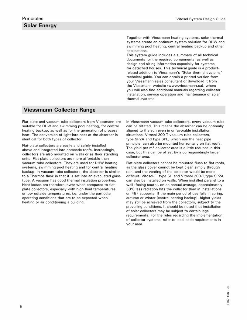
The useful energy which a collector can absorb depends on several factors. The main factor is the total solar energy available.The amount of global energy varies from location to location (see maps below).
The type of collector, as well as its inclination and orientation, are also very important (see page 12). If the solar installation is to be operated economically, careful dimensioning of the system components is alsoessential.
Note: Average mean daily global radiation on a south-facing surface tilted at an angle equal to the latitude of the location.

Vitosol System Design Guide
9
5167 1
56 -
03
Parameters for CollectorsPrinciples
Area designations
– Gross area A Describes the external dimensions (length x width) of a collector. It is important when planning the installation and when calculating the roof area required, as well as when applying for subsidies.
– Absorber area B The area of the collector that is selectively coated and is set into the collector. This is where the sun’s energy is captured and turned/converted into heat.
– Aperture area C This is the opening or the area in the collector which solar energy can pass through such that it reaches the absorber sheet.
Flat-plate collector: Area of collector cover through which solar rays can enter.
Vacuum tube collector: Since each individual evacuated tube absorber sheet is slightly shorter than the length of the evacuated tube and slightly narrower compared to the inside diameter of the evacuated tube glass, the aperture area of these devices will be slightly larger than the absorber area. The total aperture area for the collector will be the sum of all the individual tubes aperture areas combined.
Flat-plate collector
Vacuum tube collector

Vitosol System Design Guide
5167 1
56 -
03
10
Collector Efficiency
The efficiency of a collector (see chapter “Specification” for the relevant collector) specifies the proportion of insolation hitting the aperture area that can be converted into usable heat. The efficiency depends, among other things, on the operating conditions of the collector. Thecalculation method is the same for all collector types.Some of the insolation striking the collectors is “lost” through reflection and absorption at the glass pane and through absorber reflection. The ratio between the insolation striking the collector and the radiation thatis converted into heat on the absorber is used to calculate the optical efficiency 0.When the collector heats up, it transfers some of that heat to the ambient area through thermal conduction of the collector material, thermal radiation and convection. These losses are calculated by means of the heat loss factors k1 and k2 and the temperature differential ∆T (given in K) between the absorber and the surroundings:
Efficiency curves (based on collector absorber areas)The optical efficiency 0 and the heat loss factors k1 and k2 together with temperature differential ∆T and the irradiance Eg are sufficient to determine the efficiency curve. Maximum efficiency is achieved when the differential between the absorber and ambient temperature ∆T and the thermal losses is zero. The higher the collector temperature, the higher the thermal losses and the lower the efficiency.
The typical operating ranges of the collectors can be read off the efficiency curves. This gives the adjustment options of the collectors.
Typical operating ranges (see following diagram):1 Solar thermal system for DHW at low coverage2 Solar thermal system for DHW at higher coverage3 Solar thermal systems for DHW and solar central heating backup4 Solar thermal systems for process heat/solar-powered air conditioning
Principles
Vitosol System Design Guide
11
5167 1
56 -
03
Thermal CapacityThe thermal capacity in kJ/(m2 · K) indicates the amount of heat absorbed by the collector per m2 and K. This heat is only available to the system to a limited extent.
Idle Temperature
The stagnation temperature is the maximum temperature that the collector can reach during insolation of 317 Btuh/ft2
(1000 W/m2).If no heat is drawn from the collector, it will heat up until it reaches the stagnation temperature. In this state, the thermal losses are of the same magnitude as the radiation absorbed.
Steam Production CapacityThe steam production capacity in W/m2 indicates the maximum output at which a collector produces steam during stagnation and transfers it to the system, when evaporation occurs.
Solar Coverage
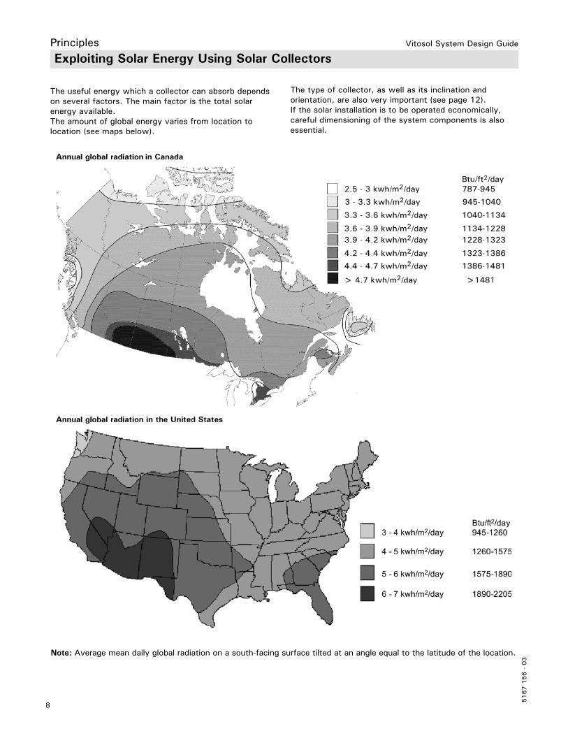
The solar coverage rate indicates what percentage of the energy required annually for DHW applications can be covered by the solar thermal system.
Designing a solar thermal system always entails finding a good compromise between yield and solar coverage. The higher the selected solar coverage, the more conventional energy is saved.
However, this is linked to an excess of heat in summer. This means a lower average collector efficiency and consequently lower yields energy in Btuh/ft2 (kWh/m2) absorber area.
Most residential solar DHW systems are sized to achieve 55 to 60% solar coverage.
Most larger commercial solar DHW systems are sized to achieve 30 to 50% solar coverage.
The maximum solar coverage recommended to avoid overheating in most DHW systems and pool systems is 60%.
A Conventional sizing for DHW systems in detached housesB Conventional sizing for large solar thermal systems
Principles
Legend

Vitosol System Design Guide
5167 1
56 -
03
12
Orientation of the Receiver SurfacePrinciples
A Collector planeB Azimuth angle
Deviation from south:15º east
An additional factor for calculating the amount of energy that can be expected is the orientation of the collector installation surface. In the northern hemisphere, an orientation towards south is ideal. The following figure shows the interaction of orientation and inclination. Relative to the horizontal, greater or lesser yields result. A range for optimum yield of a solar thermal system can be defined between south-east and southwest and at angles of inclination between 25° and 70°. Greater deviations,for example, for installation on walls, can be compensated for by a correspondingly larger collector area.
Legend

Vitosol System Design Guide
13
5167 1
56 -
03
Inclination of the receiver surfaceThe yield of a solar thermal system varies depending on the inclination and orientation of the collector area. If the collector installation surface is angled, the angle of incidence changes, as does the irradiance, and consequently the amount of energy. This is greatest when the radiation hits the collector installation surface at right angles. In our latitudes, this case never arises relative to the horizontal. Consequently, the inclination of the receiver surface can optimize the yield. In North America, a collector installation surface oriented facing south and angled 35° receives approx. 12% more energy when compared with a horizontal position.
A common rule of thumb is used when designing a solar DHW heating system to optimize the year round production of energy:Collector inclination = latitude of location.
For combination DHW + space heating suppliment systems, the collectors should be installed at a steeper angle of inclination to take advantage of lower winter sun angles and to more effectively shed snow. The rule of thumb to optimize combination systems:Collector inclination = latitude of location +15°.
Summer bias = latitude of location -15°Winter bias = latitude of location +15°
Avoiding shading of the collector installation surfaceLooking at the installation of a collector facing south, we recommend that the area between south-east and south-west is kept free of shading (at an angle towards the horizon of up to 20°). It should be remembered that the system is to operate for longer than 20 years, and thatduring this time, for example, trees would grow substantially.
Avoiding of the Receiver Surface
Inclination of the Receiver SurfacePrinciples
Vitosol System Design Guide
5167 1
56 -
03
14
Installation
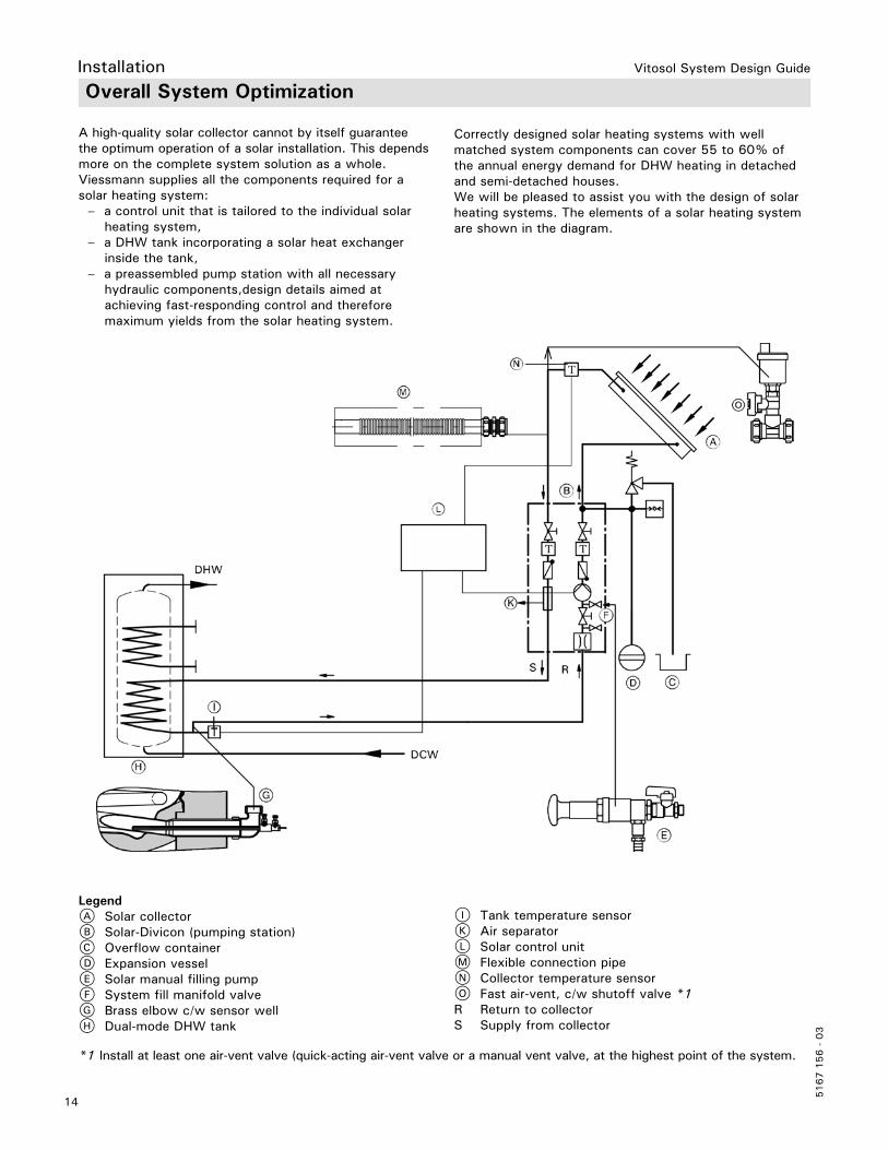
A high-quality solar collector cannot by itself guarantee the optimum operation of a solar installation. This dependsmore on the complete system solution as a whole.Viessmann supplies all the components required for a solar heating system: – a control unit that is tailored to the individual solar heating system, – a DHW tank incorporating a solar heat exchanger inside the tank, – a preassembled pump station with all necessary hydraulic components,design details aimed at achieving fast-responding control and therefore maximum yields from the solar heating system.
Overall System Optimization
Correctly designed solar heating systems with well matched system components can cover 55 to 60% ofthe annual energy demand for DHW heating in detached and semi-detached houses.We will be pleased to assist you with the design of solar heating systems. The elements of a solar heating systemare shown in the diagram.
I Tank temperature sensorK Air separatorL Solar control unitM Flexible connection pipeN Collector temperature sensorO Fast air-vent, c/w shutoff valve *1R Return to collectorS Supply from collector
*1 Install at least one air-vent valve (quick-acting air-vent valve or a manual vent valve, at the highest point of the system.
A Solar collectorB Solar-Divicon (pumping station)C Overflow containerD Expansion vesselE Solar manual filling pumpF System fill manifold valveG Brass elbow c/w sensor wellH Dual-mode DHW tank
Legend

Vitosol System Design Guide
15
5167 1
56 -
03
Product DescriptionVitosol 100-F, Type SV1 and SH1
The black chrome selectively coated absorber of the Vitosol 100-F, type SV1B/SH1B ensures a high level (95%) of absorption of the available insolation and low emission (8%) of thermal radiation. The copper pipe shaped like a meander ensures an even heat transfer at the absorber.The collector casing features heat-resistant thermal insulation and a cover made from low ferrous solar glass.Flexible connection pipes sealed with O-rings provide a secure parallel connection of up to 12 collectors.A connection set with locking ring fittings enables the collector array to be readily connected to the solar circuit pipe work. The collector temperature sensor is mounted in a sensor well set in the solar circuit supply.
• Powerful, attractively priced low profile flat-plate collector.
• Absorber designed as meander layout with integral headers. Up to 12 collectors can be linked in parallel.
• Universal application for above roof and freestanding installation — either in vertical (type SV) or horizontal (type SH) orientation. Type SH is suitable for installation on walls (when Viessmann mounting hardware is used).
• High efficiency through selectively coated absorber and cover made from low ferrous solar glass.
• Permanently sealed and highly stable through all-round folded aluminium frame and seamless pane seal.
• Puncture-proof and corrosion-resistant back panel made from zinc plated sheet steel.
• Easy to assemble Viessmann fixing system with statically-tested and corrosion-resistant components made from stainless steel and aluminium – standard for all Viessmann collectors.
• Quick and reliable collector connection through flexible corrugated stainless steel pipe push-fit connectors.
Delivered conditionThe Vitosol 100-F is delivered fully assembled ready to connect.Viessmann offers complete solar heating systems with Vitosol 200-F (Vitosol DHW solar pack) for DHW heating (see price list).
LegendA Solar glass cover, d in. (3.2 mm)B Cover bracket made from aluminiumC Pane sealD Absorber with black chrome selective surface coatingE Meander-shaped copper pipeF Thermal insulation made from mineral fibreG Aluminium frame (plain)H Steel bottom plate with an aluminium-zinc coating
Benefits

Vitosol System Design Guide
5167 1
56 -
03
16
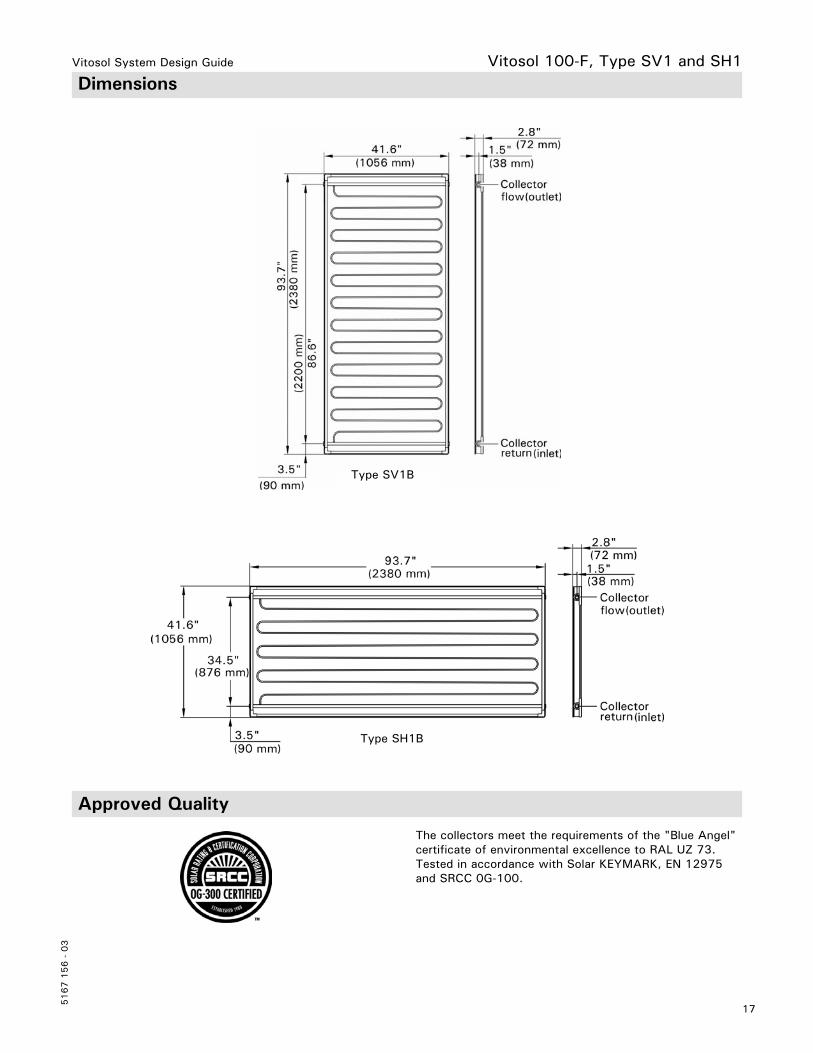
SpecificationVitosol 100-F, Type SV1 and SH1
Type SV1B SH1B
Gross area ft.2 (m2) 27.0 (2.51) 27.0 (2.51)
Absorber area ft.2 (m2) 25.0 (2.32) 25.0 (2.32)
Aperture area ft.2 (m2) 25.1 (2.33) 25.1 (2.33)
Installation position (see following diagram) A, C, D B, C, D, E
Clearance between collectors in. (mm) 0.87 (21) 0.87 (21)
DimensionsWidth Height Depth
in. (mm)in. (mm)in. (mm)
41.6 (1056) 93.7 (2380)
2.8 (72)
93.7 (2380) 41.6 (1056)
2.8 (72)
The following values apply to the absorber area: *– Optical efficiency – Heat loss factor k1 – Heat loss factor k2
%W/(m2·K)W/(m2·K)
75.4
4.15 0.0114
75.4
4.15 0.0114
Thermal capacity kJ/(m2·K) 4.5 4.5
Weight lb (kg) 96.8 (43.9) 96.8 (43.9)
Liquid content(heat transfer medium)
USG (L) 1.67 (1.67) 0.62 (2.33)
Permissible operating pressure(see chapter “Solar expansion vessel”)
psig (bar) 87 (6) 87 (6)
Max. stagnation temperature °F (°C) 385 (196) 385 (196)
Steam output– Favorable installation position – Unfavorable installation position
W/m2
W/m260
100 60
100
Connection Ø in. (Ø mm) c” (22) c” (22)
* Efficiency and heat loss factors from Solar Keymark tests (European standards).
Vitosol System Design Guide
17
5167 1
56 -
03
The collectors meet the requirements of the "Blue Angel" certificate of environmental excellence to RAL UZ 73.Tested in accordance with Solar KEYMARK, EN 12975 and SRCC 0G-100.
DimensionsVitosol 100-F, Type SV1 and SH1
Type SH1B
Type SV1B
Approved Quality

Vitosol System Design Guide
5167 1
56 -
03
18
Product DescriptionVitosol 200-F, Type SV2 and SH2
The main component of the Vitosol 200-F, type SV2C/SH2C is the sputtered highly selective coated absorber. It ensures a high absorption (95%) of insolation and low emission (5%) of thermal radiation. A meander-shaped copper pipe through which the heat transfer medium flows is part of the absorber.
The heat transfer medium absorbs the absorber heat through the copper pipe. The absorber is encased in a highly insulated collector housing that minimizes the thermal losses of the collector. The high-grade thermal insulation provides temperature stability and is free from gas emissions. The cover comprises a solar glass panel.The glass has a very low iron content, thereby reducing reflection losses.
Up to 12 collectors can be combined together to create a single collector array. For this purpose, the standard delivery includes flexible connecting pipes with O-rings. A connection set with locking ring fittings enables the collector array to be readily connected to the pipes of the solar circuit. The collector temperature sensor is mounted in a sensor well set in the solar circuit flow.
• Powerful flat-plate collector with a highly selective coated absorber.
• Absorber designed as meander layout with integral headers. Up to 12 collectors can be linked in parallel.
• Universal application for above roof and freestanding installation — either in vertical (type SV) or horizontal (type SH) orientation. Type SH is suitable for installation on walls.
• Attractive collector design; painted frame in dark blue. • The selectively coated absorber, the highly effective
thermal insulation and the cover made from low ferrous solar glass ensure a high solar yield.
• Permanently sealed and highly stable through all-round folded aluminium frame and seamless pane seal.
• Puncture-proof and corrosion-resistant back panel.• Easy to assemble Viessmann fixing system with
statically-tested and corrosion-resistant components made from stainless steel and aluminium – standard for all Viessmann collectors.
• Quick and reliable collector connection through flexible corrugated stainless steel pipe push-fit connectors.
Delivered conditionThe Vitosol 200-F is delivered fully assembled ready to connect. Viessmann offers complete solar heating systems with Vitosol 200-F (Vitosol DHW solar pack) for DHW heating (see pricelist).
A Solar glass cover, d in. (3.2 mm)B Aluminium cover stripC Pane gasketD Absorber with sputtered selective surface coatingE Meander-shaped copper pipeF Melamine epoxy foam insulationG Melamine epoxy foam insulationH Painted aluminium frameK Steel bottom plate with an aluminium-zinc coating
Legend
Benefits

Vitosol System Design Guide
19
5167 1
56 -
03
SpecificationVitosol 200-F, Type SV2 and SH2
Type SV2C SH2C
Gross area(required when applying for subsidies)
ft.2 (m2) 27.0 (2.51) 27.0 (2.51)
Absorber area ft.2 (m2) 25.0 (2.32) 25.0 (2.32)
Aperture area ft.2 (m2) 25.1 (2.33) 25.1 (2.33)
Installation position (see following diagram)
A, C, D B, C, D, E
Clearance between collectors in. (mm) 0.87 (21) 0.87 (21)
DimensionsWidth Height Depth
in. (mm)in. (mm)in. (mm)
41.6 (1056) 93.7 (2380)
3.4 (90)
93.7 (2380) 41.6 (1056)
3.4 (90)
The following values apply to the absorber area: *– Optical efficiency – Heat loss factor k1 – Heat loss factor k2
%W/(m2 · K)
W/(m2 · K2)
82.43.79
0.021
82.43.79
0.021
Thermal capacity kJ/(m2 · K) 5.0 5.0
Weight lb (kg) 90.4 (41) 90.4 (41)
Liquid content (heat transfer medium) USG (L) 0.48 (1.83) 0.66 (2.48)
Permissible operating pressure(see chapter “Solar expansion vessel”)
psig (bar) 87 (6) 87 (6)
Max. stagnation temperature °F (°C) 367 (186) 367 (186)
Steam output– Favorable installation position – Unfavorable installation position
W/m2
W/m260
10060
100
Connection Ø in. (Ø mm) c” (22) c” (22)
* Efficiency and heat loss factors from Solar Keymark tests (European standards).

Vitosol System Design Guide
5167 1
56 -
03
20
Vitosol 200-F, Type SV2 and SH2 Dimensions
Type SH2C
The collectors meet the requirements of the "Blue Angel" certificate of environmental excellence to RAL UZ 73.Tested in accordance with Solar KEYMARK, EN 12975, and SRCC 0G-100.
Type SV2C
Approved Quality
Vitosol System Design Guide
21
5167 1
56 -
03
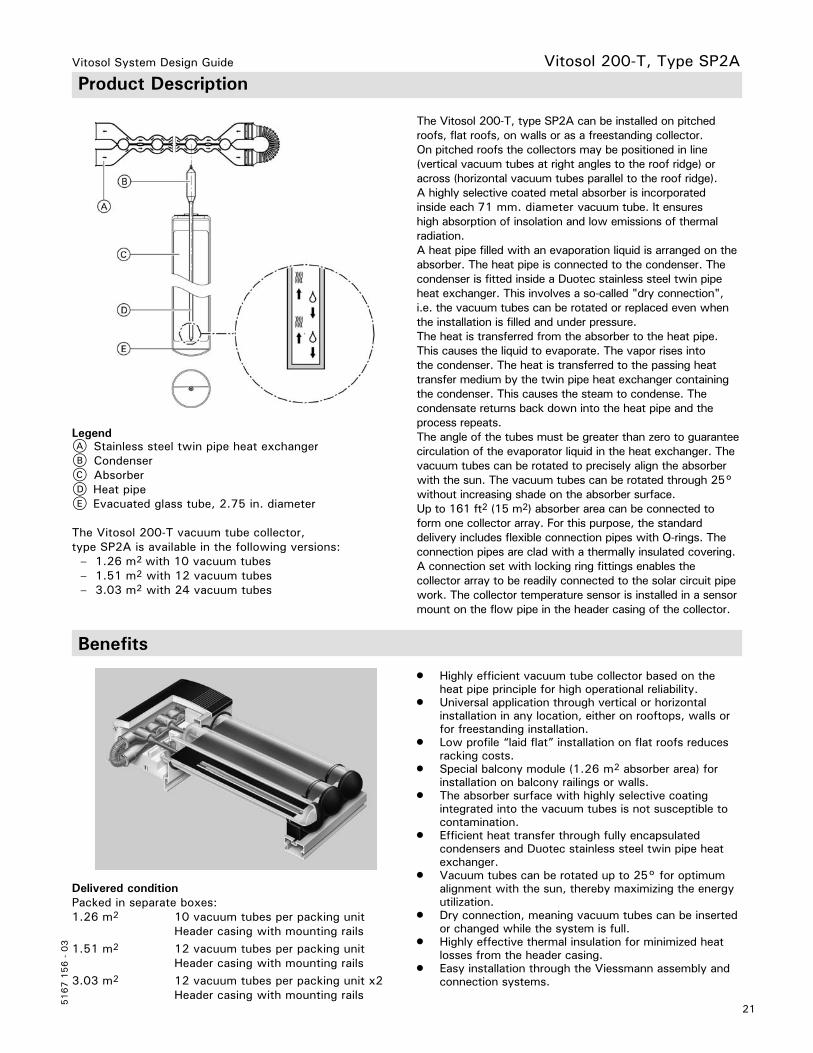
Product DescriptionVitosol 200-T, Type SP2A
The Vitosol 200-T, type SP2A can be installed on pitched roofs, flat roofs, on walls or as a freestanding collector.On pitched roofs the collectors may be positioned in line (vertical vacuum tubes at right angles to the roof ridge) or across (horizontal vacuum tubes parallel to the roof ridge).A highly selective coated metal absorber is incorporated inside each 71 mm. diameter vacuum tube. It ensures high absorption of insolation and low emissions of thermal radiation.A heat pipe filled with an evaporation liquid is arranged on the absorber. The heat pipe is connected to the condenser. The condenser is fitted inside a Duotec stainless steel twin pipe heat exchanger. This involves a so-called "dry connection", i.e. the vacuum tubes can be rotated or replaced even when the installation is filled and under pressure.The heat is transferred from the absorber to the heat pipe. This causes the liquid to evaporate. The vapor rises into the condenser. The heat is transferred to the passing heat transfer medium by the twin pipe heat exchanger containing the condenser. This causes the steam to condense. The condensate returns back down into the heat pipe and the process repeats.The angle of the tubes must be greater than zero to guarantee circulation of the evaporator liquid in the heat exchanger. The vacuum tubes can be rotated to precisely align the absorber with the sun. The vacuum tubes can be rotated through 25° without increasing shade on the absorber surface.Up to 161 ft2 (15 m2) absorber area can be connected to form one collector array. For this purpose, the standard delivery includes flexible connection pipes with O-rings. The connection pipes are clad with a thermally insulated covering.A connection set with locking ring fittings enables the collector array to be readily connected to the solar circuit pipe work. The collector temperature sensor is installed in a sensor mount on the flow pipe in the header casing of the collector.
• Highly efficient vacuum tube collector based on the heat pipe principle for high operational reliability.
• Universal application through vertical or horizontal installation in any location, either on rooftops, walls or for freestanding installation.
• Low profile “laid flat” installation on flat roofs reduces racking costs.
• Special balcony module (1.26 m2 absorber area) for installation on balcony railings or walls.
• The absorber surface with highly selective coating integrated into the vacuum tubes is not susceptible to contamination.
• Efficient heat transfer through fully encapsulated condensers and Duotec stainless steel twin pipe heat exchanger.
• Vacuum tubes can be rotated up to 25° for optimum alignment with the sun, thereby maximizing the energy utilization.
• Dry connection, meaning vacuum tubes can be inserted or changed while the system is full.
• Highly effective thermal insulation for minimized heat losses from the header casing.
• Easy installation through the Viessmann assembly and connection systems.
Delivered conditionPacked in separate boxes:1.26 m2 10 vacuum tubes per packing unit Header casing with mounting rails1.51 m2 12 vacuum tubes per packing unit Header casing with mounting rails3.03 m2 12 vacuum tubes per packing unit x2 Header casing with mounting rails
A Stainless steel twin pipe heat exchangerB CondenserC AbsorberD Heat pipeE Evacuated glass tube, 2.75 in. diameter
The Vitosol 200-T vacuum tube collector, type SP2A is available in the following versions: – 1.26 m2 with 10 vacuum tubes – 1.51 m2 with 12 vacuum tubes – 3.03 m2 with 24 vacuum tubes
Legend
Benefits
Vitosol System Design Guide
5167 1
56 -
03
22
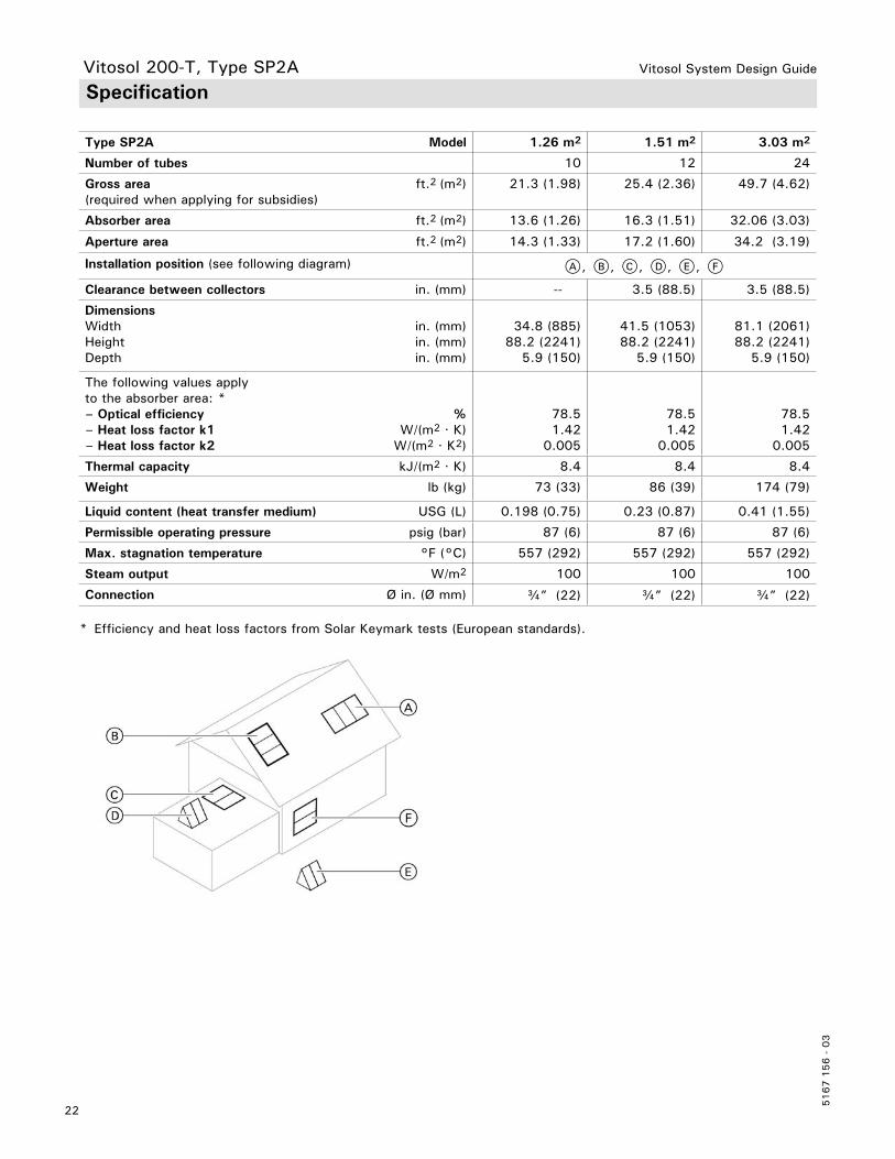
SpecificationVitosol 200-T, Type SP2A
Type SP2A Model 1.26 m2 1.51 m2 3.03 m2
Number of tubes 10 12 24
Gross area(required when applying for subsidies)
ft.2 (m2) 21.3 (1.98) 25.4 (2.36) 49.7 (4.62)
Absorber area ft.2 (m2) 13.6 (1.26) 16.3 (1.51) 32.06 (3.03)
Aperture area ft.2 (m2) 14.3 (1.33) 17.2 (1.60) 34.2 (3.19)
Installation position (see following diagram) A, B, C, D, E, F
Clearance between collectors in. (mm) -- 3.5 (88.5) 3.5 (88.5)
DimensionsWidth Height Depth
in. (mm)in. (mm)in. (mm)
34.8 (885)88.2 (2241)
5.9 (150)
41.5 (1053)88.2 (2241)
5.9 (150)
81.1 (2061)88.2 (2241)
5.9 (150)
The following values apply to the absorber area: *– Optical efficiency – Heat loss factor k1 – Heat loss factor k2
% W/(m2 · K) W/(m2 · K2)
78.5 1.42
0.005
78.5 1.42
0.005
78.5
1.42 0.005
Thermal capacity kJ/(m2 · K) 8.4 8.4 8.4
Weight lb (kg) 73 (33) 86 (39) 174 (79)
Liquid content (heat transfer medium) USG (L) 0.198 (0.75) 0.23 (0.87) 0.41 (1.55)
Permissible operating pressure psig (bar) 87 (6) 87 (6) 87 (6)
Max. stagnation temperature °F (°C) 557 (292) 557 (292) 557 (292)
Steam output W/m2 100 100 100
Connection Ø in. (Ø mm) c” (22) c” (22) c” (22)
* Efficiency and heat loss factors from Solar Keymark tests (European standards).

Vitosol System Design Guide
23
5167 1
56 -
03
The collectors meet the requirements of the "Blue Angel" certificate of environmental excellence to RAL UZ 73.Tested in accordance with Solar KEYMARK, EN 12975 and SRCC 0G-100.
DimensionsVitosol 200-T, Type SP2A
ModelWidth a Height b Depth c
in. (mm)in. (mm)in. (mm)
1.26 m2
34.8 (885) 88.2 (2241) 5.9 (150)
1.51 m2 41.5 (1053) 88.2 (2241) 5.9 (150)
3.03 m2
81.1 (2061) 88.2 (2241) 5.9 (150)
Approved Quality
Vitosol System Design Guide
5167 1
56 -
03
24
Vitosol 200-T, Type SPE Product Description
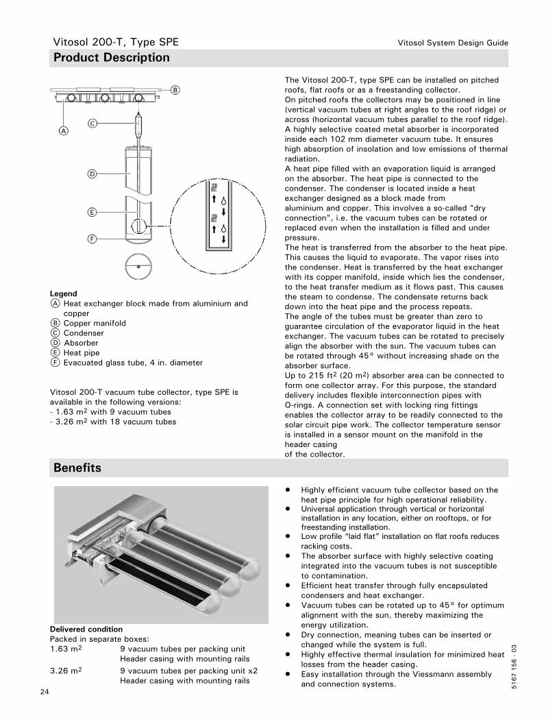
The Vitosol 200-T, type SPE can be installed on pitched roofs, flat roofs or as a freestanding collector.On pitched roofs the collectors may be positioned in line (vertical vacuum tubes at right angles to the roof ridge) or across (horizontal vacuum tubes parallel to the roof ridge). A highly selective coated metal absorber is incorporated inside each 102 mm diameter vacuum tube. It ensures high absorption of insolation and low emissions of thermal radiation.A heat pipe filled with an evaporation liquid is arranged on the absorber. The heat pipe is connected to the condenser. The condenser is located inside a heat exchanger designed as a block made fromaluminium and copper. This involves a so-called "dry connection", i.e. the vacuum tubes can be rotated or replaced even when the installation is filled and under pressure. The heat is transferred from the absorber to the heat pipe. This causes the liquid to evaporate. The vapor rises into the condenser. Heat is transferred by the heat exchanger with its copper manifold, inside which lies the condenser, to the heat transfer medium as it flows past. This causes the steam to condense. The condensate returns back down into the heat pipe and the process repeats. The angle of the tubes must be greater than zero to guarantee circulation of the evaporator liquid in the heat exchanger. The vacuum tubes can be rotated to precisely align the absorber with the sun. The vacuum tubes can be rotated through 45° without increasing shade on the absorber surface. Up to 215 ft2 (20 m2) absorber area can be connected to form one collector array. For this purpose, the standard delivery includes flexible interconnection pipes with O-rings. A connection set with locking ring fittings enables the collector array to be readily connected to the solar circuit pipe work. The collector temperature sensor is installed in a sensor mount on the manifold in the header casing of the collector.
LegendA Heat exchanger block made from aluminium and copperB Copper manifoldC CondenserD AbsorberE Heat pipeF Evacuated glass tube, 4 in. diameter
Vitosol 200-T vacuum tube collector, type SPE is available in the following versions:- 1.63 m2 with 9 vacuum tubes- 3.26 m2 with 18 vacuum tubes
• Highly efficient vacuum tube collector based on the heat pipe principle for high operational reliability.
• Universal application through vertical or horizontal installation in any location, either on rooftops, or for freestanding installation.
• Low profile “laid flat” installation on flat roofs reduces racking costs.
• The absorber surface with highly selective coating integrated into the vacuum tubes is not susceptible to contamination.
• Efficient heat transfer through fully encapsulated condensers and heat exchanger.
• Vacuum tubes can be rotated up to 45° for optimum alignment with the sun, thereby maximizing the energy utilization.
• Dry connection, meaning tubes can be inserted or changed while the system is full.
• Highly effective thermal insulation for minimized heat losses from the header casing.
• Easy installation through the Viessmann assembly and connection systems.
Delivered conditionPacked in separate boxes:1.63 m2 9 vacuum tubes per packing unit Header casing with mounting rails3.26 m2 9 vacuum tubes per packing unit x2 Header casing with mounting rails
Benefits

Vitosol System Design Guide
25
5167 1
56 -
03
SpecificationVitosol 200-T, Type SPE
Type SPE Model 1.63 m2 3.26 m2
Number of tubes 9 18
Gross area(required when applying for subsidies)
ft.2 (m2) 28.63 (2.66) 57.26 (5.32)
Absorber area ft.2 (m2) 17.55 (1.63) 35.1 (3.26)
Aperture area ft.2 (m2) 18.84 (1.75) 37.57 (3.49)
Installation position (see following diagram) A, B, C, D, E
Clearance between collectors in. (mm) 1.73 (44) 1.73 (44)
DimensionsWidth a Height b Depth c
in. (mm)in. (mm)in. (mm)
48 (1220) 89 (2260)
6.85 (174)
94 (2390) 89 (2260)
6.85 (174)
The following values apply to the absorber area: *– Optical efficiency – Heat loss factor k1 – Heat loss factor k2
%W/(m2 · K)
W/(m2 · K2)
73 1.21 0.0075
73
1.21 0.0075
Thermal capacity kJ/(m2 · K) 8.4 8.4
Weight lb (kg) 126 (57) 249 (113)
Liquid content (heat transfer medium)
USG (L) 0.124 (0.47) 0.243 (0.92)
Permissible operating pressure psig (bar) 87 (6) 87 (6)
Max. stagnation temperature °F (°C) 518 (270) 518 (270)
Steam output W/m2 100 100
Connection Ø in. (Ø mm) c” (22) c” (22)
* Efficiency and heat loss factors from Solar Keymark tests (European standards).

Vitosol System Design Guide
5167 1
56 -
03
26
Vitosol 200-T, Type SPE
Approved Quality
The collectors meet the requirements of the "Blue Angel" certificate of environmental excellence to RAL UZ 73.Tested in accordance with Solar KEYMARK, EN 12975 and SRCC 0G-100.
Model 1.63 m2
Width a Height b Depth c
in. (mm)in. (mm)in. (mm)
48 (1220) 89 (2260)
6.85 (174)
Dimensions
Model 3.26 m2 Width a Height b Depth c
in. (mm)in. (mm)in. (mm)
94 (2390) 89 (2262)
6.85 (174)

Vitosol System Design Guide
27
5167 1
56 -
03
Solar Control Units
Solar control module, type SM1 SCU 124/ 224 SCU 345
An external extension module for the Viessmann Vitotronic control based on a wall mountable casing.– Electronic temperature differential control for dual mode DHW heating and central heating backup from solar collectors in conjunction with a Viessmann boiler– Control and display via the Vitotronic boiler control unit
Electronic temperature differential controller for systems with dual mode DHW heating with solar collectors and boilers
Electronic temperature differential controller for up to three consumers for the following systems with solar collectors and boilers:– Dual mode DHW tank with dual mode DHW tanks or several tanks– Dual mode DHW and swimming pool heating– Dual mode DHW heating and central heating backup– Industrial/commercial heating systems
Functions H With output statement and diagnostic system. H Operation and display via the Vitotronic boiler control unit.
H Heating of two consumers via a collector array. H Second temperature differential controller. H Thermostat function for reheating or utilising excess heat.
H Suppression of DHW tank reheating by the boiler, subject to solar yield.
H Suppression of reheating for central heating by the heat source in the case of central heating backup.
H Heat-up of the solar preheating stage [with DHW tank having 79 USG (300 L) or 119 USG (450 L) capacity].
H Order immersion temperature sensor, part no. 7438 702, if the following functions are required:
H For DHW circulation diversion in systems with 2 DHW tanks.
H For return changeover between the heat generator and the heatingwater buffer tank.
H For heating additional consumers.
Solar Control Module SM1
Solar Control

Vitosol System Design Guide
5167 1
56 -
03
28
ConstructionThe solar control module contains: - PCB - Terminals: - 4 sensor inputs - Solar circuit pump output - 1 relay for switching an injection pump or motorized valve - KM BUS connectivity - Power supply (on-site ON/OFF switch)
Solar Control Module SM1 (continued)
Collector temperature sensorFor connection inside the module.On-site extension of the connecting lead:– 2-core copper lead, cable length up to 196 ft. (60 m) AWG 15-16 [cross-section of 0.00233 in2 (1.5 mm2)]– Never route this lead immediately next to 120/240VAC cables
Cable length 8.2 ft. (2.5 m)
Sensor type Viessmann NTC 20 kΩ, at 77°F ( 25°C)
Permissible ambient temperature:– During operation −4 to 392°F (−20 to +200°C)– During storage and transport −4 to 158°F (−20 to +70°C)
Tank temperature sensorFor connection inside the module.On-site extension of the connecting lead:– 2-core lead, length max. 197 ft. (60 m) with a cross- section of 1.5 mm2 (copper)– Never route this lead immediately next to 120/240VAC cables
Cable length 12.3 ft. (3.75 m)
Sensor type Viessmann NTC 10 kΩ, at 77°F (25°C)
Permissible ambient temperature– During operation 32 to 190°F (0 to +90°C)– During storage and transport −4 to 158°F (−20 to +70°C)
For systems with Viessmann DHW tanks, the SM1 tank temperature sensor is installed in the threaded elbow (standard delivery or accessory for the respective DHW tank) in the heating water return.
Rated voltage 120 V~Rated frequency 60 HzRated current 2 APower consumption 1.5 WSafety category I
Permissible ambient temperature:– During operation 32 to 104°F ( 0 to +40°C) use in the living space or boiler room (standard ambient conditions)
– During storage and transport −4 to 150°F (−20 to +65°C)
Rated relay output breaking capacity:– Semi-conductor relay 1 (1) A, 120 V~– Relay 2 1 (1) A, 120 V~– Total max. 2 A
– Solar control module, type SM1– Tank temperature sensor– Collector temperature sensor
Specification
Tested quality
CE designation according to current EC Directives
Delivered Condition
Solar Control

Vitosol System Design Guide
29
5167 1
56 -
03
Solar Control Solar Control Unit SCU 124
ConstructionThe control unit comprises:– PCB– LCD– Selector keys– Connection terminals: – Sensors (4) inputs – Solar circuit pump output – Relay for actuating pumps and valves – VBus connectivity – Power supply (on-site ON/OFF switch)– Variable speed output for controlling the solar circuit pumpThe standard delivery includes 1x collector temperature sensor, 2x tank temperature sensors
Functions
H Switching the solar circuit pump for DHW and/or swimming pool heating or space heating
H Electronic limiter for the temperature in the DHW tank (safety shutdown at 194°F (90°C)
H Collector safety shutdown and collector cooling
H 3 basic system layouts
H operating hour counter for relays
H Energy metering
H thermostat function
H Heat dump functionFor further functions, see page 32.
SpecificationsRated voltage 100 - 240VACRated frequency 60 HzRated current 4APower consumption 2 W (in standby mode 0.7 W)Safety category IIPermissible ambient temperature:– during operation 32 to 104°F (0 to +40°C) for use in the living space or boiler room – during storage and transport −4 to 150°F (−20 to +65°C)Rated relay output breaking capacity: – Semi-conductor relay 1 1 A– Semi-conduction relay 2 1 A– Total max. 2 A
– SCU 124– 2x tank temperature sensors– 1x collector temperature sensor
Tank temperature sensorFor connection inside the control.On-site extension of the connecting lead:– 2-core lead, cable length up to 196 ft. (60 m) with a cross-section of 1.5 mm2 (copper)– Never route this lead immediately next to 120/240VAC cablesCable length 8.2 ft. (2.5 m)Sensor type PT1000
Permissible ambient temperature:– during operation 23 to 176°F (−5 to +80°C)– during storage and transport −4 to 158°F (−20 to +70°C)
Collector temperature sensorFor connection inside the control.On-site extension of the connecting lead:– 2-core copper lead, cable length up to 196 ft. (60 m) AWG 15-16 [cross-section of 0.00233 in2 (1.5 mm2)]– Never route this lead immediately next to 120/240 V cables
Cable length 5 ft. (1.5 m)
Sensor type PT1000
Permissible ambient temp.– during operation 23 to 356°F (−5 to 180°C)– during storage and transport −4 to 158°F (−20 to +70°C)
Delivered Condition
For systems with Viessmann DHW tanks, the tank temperature sensor is installed in the threaded elbow (see chapter “Specification” of the relevant DHW tank and chapter “Installation accessories”) in the heating water return.

Vitosol System Design Guide
5167 1
56 -
03
30
Solar Control Unit SCU 224
ConstructionThe control unit comprises:– PCB– LCD– Selector keys– Connection terminals: – Sensors (4) inputs – Solar circuit pump output – Relay for actuating pumps and valves – VBus connectivity – Power supply (on-site ON/OFF switch)– Variable speed output for controlling the solar circuit pumpThe standard delivery includes 2x collector temperature sensor, 2x tank temperature sensor
Functions
H 10 basic system layouts
H Control of 2 collector fields
H Control of 2 storage tanks
H heat dump function
H Switching the solar circuit pump for DHW and/or swimming pool heating
H Electronic limiter for the temperature in the DHW tank (safety shutdown at 194°F (90°C)
H Collector safety shutdown and collector coding
H operating hour counter for relays
H Energy metering
H thermostat functionFor further functions, see page 32.
Tank temperature sensorFor connection inside the appliance.On-site extension of the connecting lead:– 2-core copper lead, cable length up to 196 ft. (60 m) AWG 15-16 [cross-section of 0.00233 in2 (1.5 mm2)]– Never route this lead immediately next to 120/240VAC cablesCable length 8.2 ft. (2.5 m)Sensor type PT1000
Permissible ambient temperature: – during operation 23 to 176°F (–5 to 180°C) – during storage and transport −4 to 158°F (−20 to +70°C)
Collector temperature sensorFor connection inside the control.On-site extension of the connecting lead:– 2-core copper lead, cable length up to 196 ft. (60 m) AWG 15-16 [cross-section of 0.00233 in2 (1.5 mm2)]– Never route this lead immediately next to 120/240VAC cablesCable length 5ft. (1.5 m)
Sensor type PT1000
Permissible ambient temperature:– during operation 23 to 356°F (−5 to 180°C) – during storage and transport −4 to 158°F (−20 to +70°C)
SpecificationsRated voltage 100 - 240VACRated frequency 60 HzRated current 4 APower consumption 2 W (in standby mode 0.7 W)Safety category IIPermissible ambient temperature: – during operation 32 to 104°F (0 to +40°C) for use in the living space or boiler room – during storage and transport −4 to 150°F (−20 to +65°C) Rated relay output breaking capacity: – Semi-conductor relay 1 1 A– Semi-conduction relay 2 1 A– Total max. 2 A
– SCU 124– 2x tank temperature sensors– 2x collector temperature sensors
Delivered Condition
Solar Control
For systems with Viessmann DHW tanks, the tank temperature sensor is installed in the threaded elbow (see chapter “Specification” of the relevant DHW tank and chapter “Installation accessories”) in the heating water return.
Vitosol System Design Guide
31
5167 1
56 -
03
Solar Control Solar Control Unit SCU 345
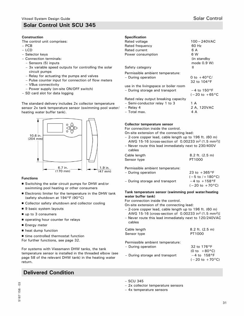
ConstructionThe control unit comprises:– PCB– LCD– Selector keys– Connection terminals: – Sensors (5) inputs – 3x variable speed outputs for controlling the solar circuit pumps – Relay for actuating the pumps and valves – Pulse counter input for connection of flow meters – VBus connectivity – Power supply (on-site ON/OFF switch)– SD card slot for data logging
For systems with Viessmann DHW tanks, the tank temperature sensor is installed in the threaded elbow (see page 58 of the relevant DHW tank) in the heating water return.
Functions
H Switching the solar circuit pumps for DHW and/or swimming pool heating or other consumers
H Electronic limiter for the temperature in the DHW tank (safety shutdown at 194°F (90°C)
H Collector safety shutdown and collector cooling
H 9 basic system layouts
H up to 3 consumers
H operating hour counter for relays
H Energy meter
H heat dump function
H time controlled thermostat functionFor further functions, see page 32.
Collector temperature sensorFor connection inside the control.On-site extension of the connecting lead:– 2-core copper lead, cable length up to 196 ft. (60 m) AWG 15-16 [cross-section of 0.00233 in2 (1.5 mm2)]– Never route this lead immediately next to 230/400V cables
SpecificationRated voltage 100−240VACRated frequency 60 HzRated current 6 APower consumption 6 W (in standby mode 0.9 W)Safety category II
Cable length 8.2 ft. (2.5 m)Sensor type PT1000 Permissible ambient temperature:– During operation 23 to +365°F (−5 to /+180°C)– During storage and transport −4 to +158°F (−20 to +70°C)
Tank temperature sensor (swimming pool water/heating water buffer tank)For connection inside the control.On-site extension of the connecting lead:– 2-core copper lead, cable length up to 196 ft. (60 m) AWG 15-16 [cross-section of 0.00233 in2 (1.5 mm2)]– Never route this lead immediately next to 120/240VAC cables
Cable length 8.2 ft. (2.5 m)Sensor type PT1000
Permissible ambient temperature:– During operation 32 to 176°F (0 to +80°C)– During storage and transport −4 to 158°F (−20 to +70°C)
The standard delivery includes 2x collector temperature sensor 2x tank temperature sensor (swimming pool water/ heating water buffer tank).
Permissible ambient temperature:– During operation 0 to +40°C/ 32 to 104°F use in the livingspace or boiler room – During storage and transport −4 to 150°F (−20 to +65°CRated relay output breaking capacity– Semi-conductor relay 1 to 3 1 A– Relay 4 2 A, 120VAC– Total max. 4 A
– SCU 345– 2x collector temperature sensors– 4x temperature sensors
Delivered Condition

Vitosol System Design Guide
5167 1
56 -
03
32
Allocation to Solar Control Units
Function Solar control module SM1 SCU 124 / 224 SCU 345
Tank temperature limit x x xCollector cooling function -- x xTank cooling function -- x xCollector emergency shutdown x x xMinimum collector temperature limit x x xEvacuated tube collector function x x xFrost protection function x x xThermostat function x x xSpeed regulation with wave packet control/PWM output control *
x x x
Energy metering x x x
Suppression of reheating by the boiler– DHW tank
x -- --
– Central heating backup x -- --External heat exchanger x x (224) xParallel relay -- -- xTank 2 ON -- x (224) xTank 2 to 3 ON -- -- xTank priority control -- x xUtilisation of excess heat(heat dump)
-- x x
Cyclical heating x x x
Relay kick x -- xSD Card -- -- x
Tank Temperature Limit
The solar circuit pump will be switched OFF if the set tank temperature is exceeded.
Collector Emergency Shutdown
In order to protect the system components, the solar circuit pump is switched off if the adjustable collector maximum limit temperature is exceeded. The pump is kept off until the collector cools below the limit.
Minimum Collector Temperature Limit
The solar circuit pump will be blocked if the minimum collector array temperature is not achieved.
Solar Control
* Only applies to high efficiency pumps (does not apply to Solar Divicon).

Vitosol System Design Guide
33
5167 1
56 -
03
Solar Control Collector Cooling Function with SCU 124 / 224 / 345
The solar circuit pump will be switched off when the maximum tank temperature is reached. The control will allow the collector temperature to increase until it reaches a user defined temperature. Then the solar circuit pump will be switched on long enough to enable the collector this temperature to fall by 9ºRa (5 K). This process will continue until the solar tank temperature increases to a maximum of 203ºF (95ºC).
Tank Cooling Function with SCU 124 / 224 / 345
Information Regarding the Collector Cooling and Tank Cooling Functions
Ensure the intrinsic safety of the solar thermal system, even if the collector temperature continues to rise after the system has reached all limit temperatures, by accurately sizing the diaphragm expansion vessel.Where stagnation occurs or for collector temperatures that rise further, the solar circuit pump will be blocked or stopped (emergency collector shutdown) to avoid thermal overloading of the connected components.
Tank cooling functionThis function is only available if the collector cooling function has been enabled. If the maximum tank temperature has been exceeded, the solar circuit pump will be started once the collectors are cooler than the solar tank. The pump will run for as long as required to cool the solar tank, to the selected maximum tank temperature. The reduction in tank temperature will come from the thermal losses via the collector array and pipe work (works best with flat plate collectors).

Vitosol System Design Guide
5167 1
56 -
03
34
Evacuated Tube Collector Function
This function is used for systems where the collector temperature sensor is not able to directly sense the internal fluids temperature or when the collector sensor is improperly located. The solar control will switch on the solar circuit pump for a defined amount of time then it will turn off the pump for another period of time.This pump oscillation will operate between a time frame specified upon commissioning. This feature allows the fluid to be forced past the collector sensor thus allowing it to measure the interior collector temperature and make the required operational decisions.Activate this interval function in systems where the collector temperature sensor is not in an ideal location to prevent a time delay in capturing the collector temperature. This function can be used for any collector type with improperly located collector sensor.
Frost Protection
H Solar control module SM1 With a collector temperature below 41°F (5ºC), the solar circuit pump will be started to avoid damage to the collectors. The pump will be stopped when a temperature of 45°F (7ºC) has been reached. Assuming the same as SCU controls.
H SCU 124 / 224 / 345 With a collector temperature below 39°F (4ºC), the solar circuit pump will be started to avoid damage to the collectors. The pump will be stopped when a temperature of 39°F (5ºC) has been reached or when the solar tank temperature drops below 42°F (5ºC).
Thermostat Function with Time Switches Solar Control Module SM1 and SCU 124, 224 and 345
The thermostat function can be used independent of the solar operation. Different effects can be achieved by determining the thermostat start and stop temperatures:– Start temperature < stop temperature: e.g. reheating– Start temperature > stop temperature: e.g. utilization of excess heatStart temperature 104°F (40ºC) and stop temperature113°F (45ºC) can be changed.Start temperature setting range: 30 to 200°F (0 to 95ºC)Stop temperature setting range: 30 to 200°F (0 to 95ºC)
H Time switch with 3 periods that can be enabled The functions within a function block are linked so that the conditions for all enabled functions must be met.
Solar Control
If Viessmann collectors are filled with Viessmann heat transfer medium Tyfocor HTL. This function does not have to be enabled. Activate only when using water as heat transfer medium.

Vitosol System Design Guide
35
5167 1
56 -
03
SCU 224 and 345 ∆T Control with Temperature Limitations
H Upper and lower temperature limits
H Differential temperature control
Solar Control
∆T controlsThe corresponding relay switches ON if the start temperature differential is exceeded and OFF if the stop temperature is not achieved.
This function is used for loading or unloading tanks.The control will monitor both tanks to see if there is usable heat that can be utilized. The control has 3 sets of criteria that must be achieved before the heat exchange will occur.
1. The heat source must be greater than the defined minimum temperature (or Switch ON temperature).
2. The heat source must be greater than the heat sink as defined by the Switch ON temperature differential.
3. The heat sink must be lower than the defined maximum temperature (or Switch OFF temperature).
Note: If the system temperature is within this criteria, the heat exchange will begin. It will continue until 1 or more sets of criteria have not been achieved.
Vitosol System Design Guide
5167 1
56 -
03
36
Solar Control
SCU 124/ 224 Speed Control
The speed control is disabled in the factory default condition. It can be enabled for relay output R1 and R2.Possible pumps:– Standard solar pumps with and without their own speed control– High efficiency pumps (with optional module)
Note: We recommend operating the solar circuit pump at max. output while the solar thermal system is being commissioned and vented of air.
SCU 345 Speed Control
Speed Control with Solar Control Module SM1The speed control is disabled in the factory default condition, during commissioning it can be enabled for relay output R1.Possible pumps:– Standard solar pumps with and without their own speed control– High efficiency pumps (with optional module)– Pumps with PWM input (only use solar pumps), e.g. Wilo or Grundfos pumps
Note: We recommend operating the solar circuit pump at max. output while the solar thermal system is being commissioned and vented of air.
The speed control is disabled in the factory default condition. It can be enabled for relay output R1, R2 and R3.Possible pumps:– Standard solar pumps with and without their own speed control– High efficiency pumps (with optimal module)– Pumps with PWM input (only use solar pumps), e.g. Wilo or Grundfos pumps
Note: We recommend operating the solar circuit pump at max. output while the solar thermal system is being commissioned and vented of air.

Vitosol System Design Guide
37
5167 1
56 -
03
Solar Control Energy Metering with Solar Control Module SM1 and SCU 124 and 224
When determining thermal yields, the difference between the collector and tank temperature, the calculated flowrate, the type of heat transfer medium and the operating time of the solar circuit pump are taken into account. The maximum flowrate is entered in the control at the time of commissioning and the energy production is calculated.
Note: The maximum flowrate as visually measured from the pump station flowmeter must be entered in the control. This is to be done during commissioning and the control will calculate the energy produced by the solar system.
SCU 345 Energy Metering
The statement can be produced with or without the use of a flowmeter.
H Without flowmeter through the temperature differential between the heat supply and the return temperature sensors and the entered flowrate from the pump station flowmeter.
H With flowmeter (accessory for the SCU 345) through the temperature differential between the heat supply and the heat return temperature sensors and the measured flow rate as captured by the flow meter.
Note: Existing sensors can be used, without affecting their function in the relevant system scheme.
Suppression of DHW Tank Reheating by the Boiler with Solar Control Module SM1
DHW tank reheating by the boiler is suppressed in two stages. While the DHW tank is being heated by solar energy, the set tank temperature is reduced. After the solar circuit pump has been switched off, suppression remains active for a certain time.If solar heating is uninterrupted (> 2 h), reheating by the boiler only occurs when the temperature falls below the 3rd set DHW temperature, as set at the boiler control unit (at coding address “67”) [setting range 50 to 203°F (10 to 95ºC)]. This value must be below the first set DHW temperature.The DHW tank will only be heated by the boiler, if this set value cannot be achieved by the solar thermal system.
If a sufficiently high temperature is available in the multi-mode heating water buffer cylinder to heat the heating circuits, reheating is suppressed.

Vitosol System Design Guide
5167 1
56 -
03
38
Solar Control
External Heat Exchanger with Solar Control Module SM1
The DHW tank is heated via the heat exchanger. The secondary pump sS starts in parallel with solar circuit pump sF. If an additional temperature sensor / is used, secondary pump sS starts when solar circuit pump sF is running and the required temperature differential between sensors % and / is given.
Auxiliary Function for DHW Heating with Solar Control Module SM1
For detailed information see chapter “Auxiliary function for DHW heating”. Only possible in conjunction with Vitotronic control units with KM BUS.Control units from the current Viessmann product range are equipped with the necessary software.
Boiler control unit settings:
H The set DHW temperature 2 must be encoded
H The DHW phase 4 for DHW heating must be enabled Via KM BUS, this signal will be transferred to the SM1 control, and the transfer pump (relay #2) will be started.
Option #1: The DHW tank is heated via an external heat exchanger. The control uses only 2 sensors to operate the primary and secondary pumps. The control monitors the temperature differential between sensors & and %, should there be usable heat, then pumps sF and sS will start at the same time or in parallel.
Option #2: The DHW tank is heated via external heat exchanger. The control uses 3 sensors to operate the primary and secondary pumps independently. The control monitors the temperature differential between sensors& and %, should there be usable heat then pump sF will start. The control will monitor the heat exchanger to see if it has usable heat. If the differential between sensors / and % is achieved then the control will start pump sS.

Vitosol System Design Guide
39
5167 1
56 -
03
Option #1: The DHW tank is heated via the heat exchanger. Secondary pump P2 starts in parallel with solar circuit pump P1. This is done by using the external relay connected to the glycol pump output of the control R1.
Option #2: The DHW tank is heated via the heat exchanger. The primary pump P1 operates base on temperature differential between S1 and S2. The secondary pump P2 operates based on temperature differential between S3 and S2.
External Heat Exchanger with SCU 224/345Solar Control
Parallel Relay with SCU 345
With this function, a further relay will be switched (subject to the system scheme) in addition to the relay (R1) that switches the circulation pump, e.g. to control a diverter valve or a second pump.
Multiple Tank Operation with SCU 224 and 345
In systems with several consumers. With this function, consumers can be excluded from solar heating.Note: Only with the SCU 345 can the user deactivate a tank or load from the scheme. The SCU 224, the proper scheme must be used to reflect the true hydraulic layout.
Tank Priority Control with SCU 224 and 345In systems with several consumers. It is possible to determine the order for heating the consumers.
In systems with several consumers. If the consumer cannot be heated with priority, the next consumer inline will be heated for an adjustable cycle time. After this time has expired, the solar control unit checks the rise of the collector temperature during the adjustable cyclical pause. As soon as the start conditions for the consumer with priority have been met, that consumer will be heated again. Otherwise, the next-in-line consumers will continueto be heated.
Vitosol System Design Guide
5167 1
56 -
03
40
Relay Kick with Solar Control Module SM1
If the pumps and valves have been switched off for 24 hours, they are started for approx. 10 sec. to prevent them seizing up.
SD Card with SCU 345
SD card to be provided on site with a memory capacity ≤ 2 GB and file system FAT16.Note: Never use SD-HC modules.
The SD card is inserted into the SCU 345.
H To record the operating values of the solar thermal system.
H Saving the values to the SD card in a Excel file.
The values can therefore also be visualized.
Solar Control
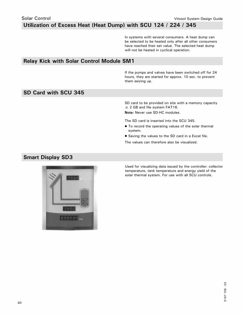
Smart Display SD3
Used for visualizing data issued by the controller: collector temperature, tank temperature and energy yield of the solar thermal system. For use with all SCU controls.
Utilization of Excess Heat (Heat Dump) with SCU 124 / 224 / 345
In systems with several consumers. A heat dump can be selected to be heated only after all other consumershave reached their set value. The selected heat dump will not be heated in cyclical operation.
Vitosol System Design Guide
41
5167 1
56 -
03
Solar Control
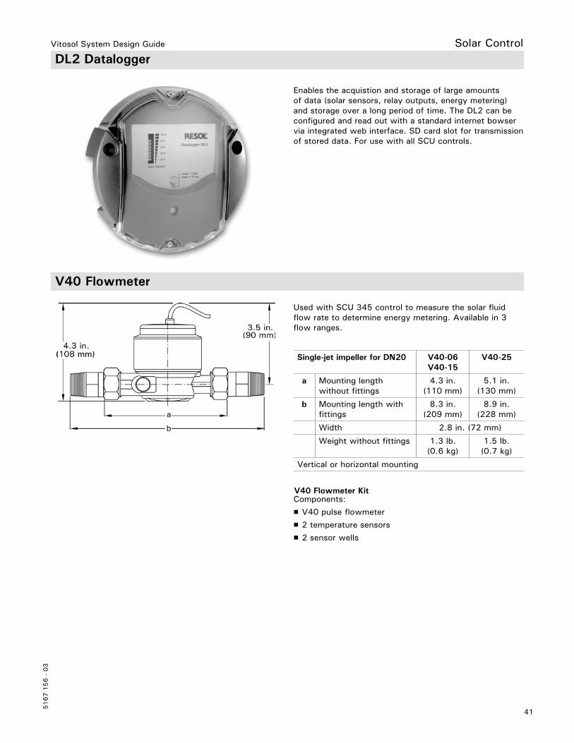
V40 Flowmeter
Components:
H V40 pulse flowmeter
H 2 temperature sensors
H 2 sensor wells
Enables the acquistion and storage of large amounts of data (solar sensors, relay outputs, energy metering) and storage over a long period of time. The DL2 can be configured and read out with a standard internet bowser via integrated web interface. SD card slot for transmission of stored data. For use with all SCU controls.
Used with SCU 345 control to measure the solar fluid flow rate to determine energy metering. Available in 3 flow ranges.
DL2 Datalogger
V40 Flowmeter Kit
Single-jet impeller for DN20 V40-06V40-15
V40-25
a Mounting length without fittings
4.3 in. (110 mm)
5.1 in. (130 mm)
b Mounting length with fittings
8.3 in. (209 mm)
8.9 in. (228 mm)
Width 2.8 in. (72 mm)
Weight without fittings 1.3 lb. (0.6 kg)
1.5 lb. (0.7 kg)
Vertical or horizontal mounting

Vitosol System Design Guide
5167 1
56 -
03
42
Solar Control V40 Flowmeter Technical Data
Vitosol System Design Guide
43
5167 1
56 -
03
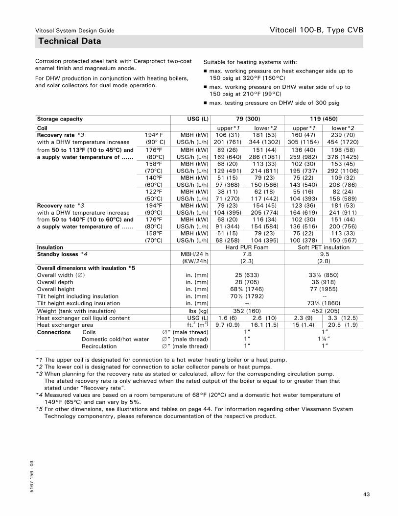
Technical Data
Suitable for heating systems with:
H max. working pressure on heat exchanger side up to 150 psig at 320°F (160°C)
H max. working pressure on DHW water side of up to 150 psig at 210°F (99°C)
H max. testing pressure on DHW side of 300 psig
Corrosion protected steel tank with Ceraprotect two-coat enamel finish and magnesium anode.
For DHW production in conjunction with heating boilers,and solar collectors for dual mode operation.
Storage capacity USG (L) 79 (300) 119 (450)
Coil upper*1 lower*2 upper*1 lower*2Recovery rate *3with a DHW temperature increase
194º F (90º C)
MBH (kW)USG/h (L/h)
106 (31)201 (761)
181 (53)344 (1302)
160 (47)305 (1154)
239 (70)454 (1720)
from 50 to 113ºF (10 to 45ºC) and a supply water temperature of ......
176ºF (80ºC)
MBH (kW)USG/h (L/h)
89 (26)169 (640)
151 (44)286 (1081)
136 (40)259 (982)
198 (58)376 (1425)
158ºF(70ºC)
MBH (kW)USG/h (L/h)
68 (20)129 (491)
113 (33)214 (811)
102 (30)195 (737)
153 (45)292 (1106)
140ºF (60ºC)
MBH (kW) USG/h (L/h)
51 (15)97 (368)
79 (23)150 (566)
75 (22)143 (540)
109 (32)208 (786)
122ºF(50ºC)
MBH (kW)USG/h (L/h)
38 (11)71 (270)
62 (18)117 (442)
55 (16)104 (393)
82 (24)156 (589)
Recovery rate *3with a DHW temperature increase
194ºF(90ºC)
MBH (kW) USG/h (L/h)
79 (23)104 (395)
154 (45)205 (774)
123 (36)164 (619)
181 (53)241 (911)
from 50 to 140ºF (10 to 60ºC) and a supply water temperature of ......
176ºF(80ºC)
MBH (kW)USG/h (L/h)
68 (20)91 (344)
116 (34)154 (584)
102 (30)136 (516)
151 (44)200 (756)
158ºF(70ºC)
MBH (kW)USG/h (L/h)
51 (15)68 (258)
79 (23)104 (395)
75 (22)100 (378)
113 (33)150 (567)
Insulation Hard PUR Foam Soft PET insulationStandby losses *4 MBH/24 h
(KW/24h)7.8
(2.3) 9.5(2.8)
Overall dimensions with insulation *5Overall width (∅)Overall depthOverall heightTilt height including insulationTilt height excluding insulation
in. (mm)in. (mm)in. (mm)in. (mm)in. (mm)
25 (633)28 (705)
68¾ (1746)70½ (1792)
--
33½ (850)36 (918)77 (1955)
--73d (1860)
Weight (tank with insulation) lbs (kg) 352 (160) 452 (205)Heat exchanger coil liquid content USG (L) 1.6 (6) 2.6 (10) 2.3 (9) 3.3 (12.5)Heat exchanger area ft.2 (m2) 9.7 (0.9) 16.1 (1.5) 15 (1.4) 20.5 (1.9)Connections Coils ∅” (male thread) Domestic cold/hot water ∅” (male thread) Recirculation ∅” (male thread)
1”1”1”
1”1¼” 1”
Vitocell 100-B, Type CVB
*1 The upper coil is designated for connection to a hot water heating boiler or a heat pump.*2 The lower coil is designated for connection to solar collector panels or heat pumps.*3 When planning for the recovery rate as stated or calculated, allow for the corresponding circulation pump. The stated recovery rate is only achieved when the rated output of the boiler is equal to or greater than that stated under “Recovery rate”.*4 Measured values are based on a room temperature of 68°F (20ºC) and a domestic hot water temperature of 149°F (65ºC) and can vary by 5%.*5 For other dimensions, see illustrations and tables on page 44. For information regarding other Viessmann System Technology componentry, please reference documentation of the respective product.

Vitosol System Design Guide
5167 1
56 -
03
44
E DrainHR Heating water returnHRs Heating water return, solar thermal systemHV Heating water supplyHVs Heating water supply, solar thermal systemKW Cold waterR Inspection and cleaning aperture with flange cover SPR1 Tank temperature sensor of the tank temperature controllerSPR2 Temperature sensors/thermometerTH ThermometerVA Protective magnesium anodeWW DHWZ DHW circulation
Legend
Tank 119 USG (450 L) Dimensions
a in. (mm) 33.8 (859) i in. (mm) 41.1 (1044)
b in. (mm) 36.3 (923) j in. (mm) 36.3 (924)
c in. (mm) 34.7 (881) k in. (mm) 13.7 (349)
d in. (mm) 25.6 (650) l in. (mm) 4.2 (107)
e in. (mm) 76.7 (1948) m in. (mm) 17.9 (455)
f in. (mm) 70.2 (1784) n in. (mm) 3.9 (100)
g in. (mm) 56.8 (1444) o in. (mm) 16.6 (422)
h in. (mm) 48.4 (1230) p in. (mm) 38.7 (984)
Tank 79 USG (300 L) Dimensions
a in. (mm) 24.9 (633) h in. (mm) 39.2 (995)
b in. (mm) 27.9 (705) i in. (mm) 34.4 (875)
c in. (mm) 13.5 (343) j in. (mm) 19.2 (260)
d in. (mm) 68.7 (1746) k in. (mm) 3.0 (76)
e in. (mm) 63.0 (1600) l in. (mm) 3.9 (100)
f in. (mm) 53.4 (1355) m in. (mm) 13.1 (333)
g in. (mm) 43.9 (1115) n in. (mm) 36.8 (935)
Tank 119 USG (450 L) Note: For tank 79 USG (300 L) legend see below.
Vitocell 100-B, Type CVB
Tank 79 USG (300 L)
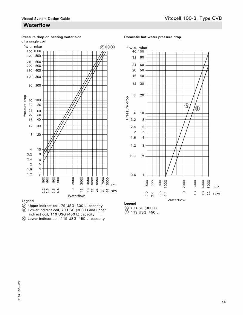
Vitosol System Design Guide
45
5167 1
56 -
03
Vitocell 100-B, Type CVB Waterflow
Pressure drop on heating water side Domestic hot water pressure dropof a single coil
A Upper indirect coil, 79 USG (300 L) capacityB Lower indirect coil, 79 USG (300 L) and upper indirect coil, 119 USG (450 L) capacityC Lower indirect coil, 119 USG (450 L) capacity
A 79 USG (300 L)B 119 USG (450 L)
LegendLegend
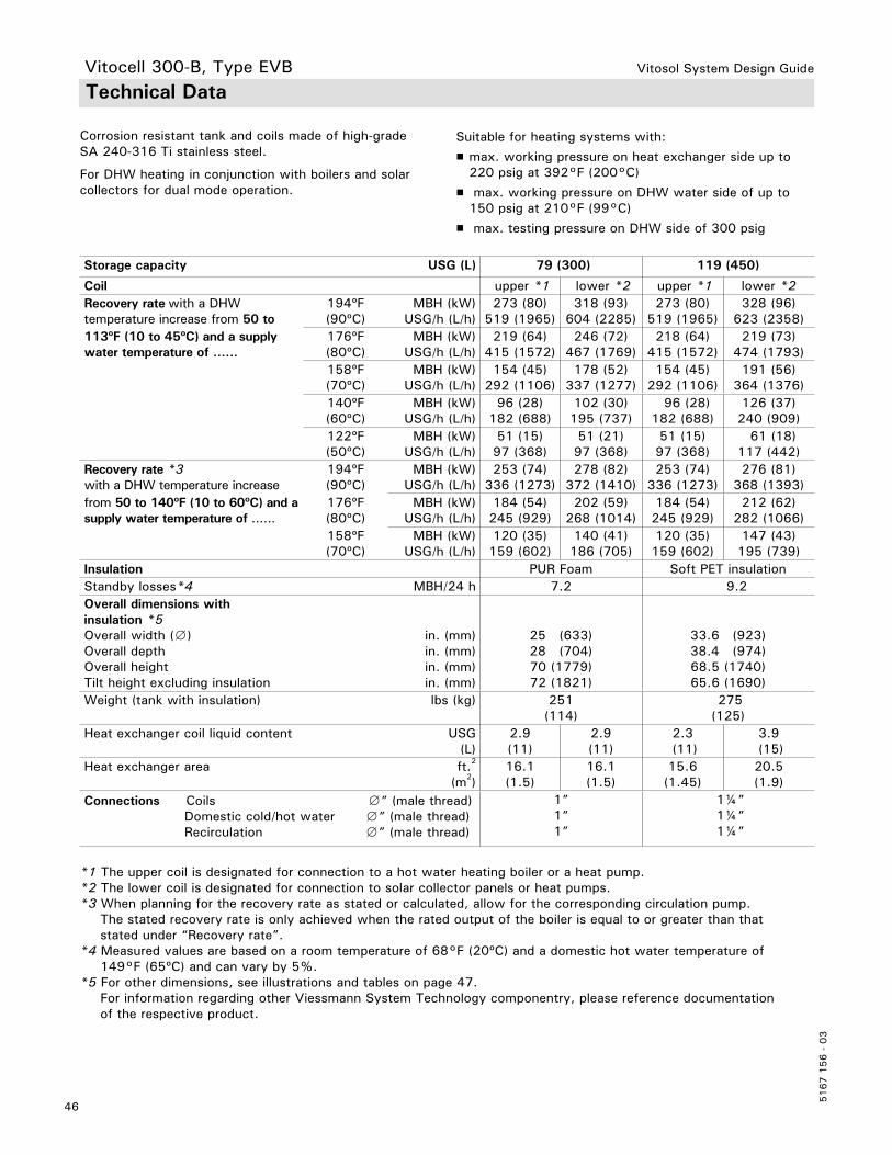
Vitosol System Design Guide
5167 1
56 -
03
46
Technical Data
Corrosion resistant tank and coils made of high-grade SA 240-316 Ti stainless steel.
For DHW heating in conjunction with boilers and solar collectors for dual mode operation.
Suitable for heating systems with:
H max. working pressure on heat exchanger side up to 220 psig at 392°F (200°C)
H max. working pressure on DHW water side of up to 150 psig at 210°F (99°C)
H max. testing pressure on DHW side of 300 psig
Storage capacity USG (L) 79 (300) 119 (450)
Coil upper *1 lower *2 upper *1 lower *2Recovery rate with a DHW temperature increase from 50 to
194ºF(90ºC)
MBH (kW)USG/h (L/h)
273 (80)519 (1965)
318 (93)604 (2285)
273 (80)519 (1965)
328 (96)623 (2358)
113ºF (10 to 45ºC) and a supply water temperature of ......
176ºF(80ºC)
MBH (kW) USG/h (L/h)
219 (64)415 (1572)
246 (72)467 (1769)
218 (64)415 (1572)
219 (73)474 (1793)
158ºF(70ºC)
MBH (kW) USG/h (L/h)
154 (45)292 (1106)
178 (52)337 (1277)
154 (45)292 (1106)
191 (56)364 (1376)
140ºF(60ºC)
MBH (kW) USG/h (L/h)
96 (28)182 (688)
102 (30)195 (737)
96 (28)182 (688)
126 (37)240 (909)
122ºF(50ºC)
MBH (kW) USG/h (L/h)
51 (15)97 (368)
51 (21)97 (368)
51 (15)97 (368)
61 (18)117 (442)
Recovery rate *3with a DHW temperature increase
194ºF(90ºC)
MBH (kW) USG/h (L/h)
253 (74)336 (1273)
278 (82)372 (1410)
253 (74)336 (1273)
276 (81)368 (1393)
from 50 to 140ºF (10 to 60ºC) and a supply water temperature of ......
176ºF(80ºC)
MBH (kW)USG/h (L/h)
184 (54)245 (929)
202 (59)268 (1014)
184 (54)245 (929)
212 (62)282 (1066)
158ºF(70ºC)
MBH (kW)USG/h (L/h)
120 (35)159 (602)
140 (41)186 (705)
120 (35)159 (602)
147 (43)195 (739)
Insulation PUR Foam Soft PET insulationStandby losses*4 MBH/24 h 7.2 9.2Overall dimensions withinsulation *5Overall width (∅)Overall depthOverall heightTilt height excluding insulation
in. (mm)in. (mm)in. (mm)in. (mm)
25 (633) 28 (704)70 (1779)72 (1821)
33.6 (923)38.4 (974)68.5 (1740) 65.6 (1690)
Weight (tank with insulation) lbs (kg) 251(114)
275 (125)
Heat exchanger coil liquid content USG (L)
2.9(11)
2.9(11)
2.3 (11)
3.9 (15)
Heat exchanger area ft.2
(m2)16.1(1.5)
16.1(1.5)
15.6(1.45)
20.5(1.9)
Connections Coils ∅” (male thread) Domestic cold/hot water ∅” (male thread) Recirculation ∅” (male thread)
1”1”1”
1¼” 1¼” 1¼”
*1 The upper coil is designated for connection to a hot water heating boiler or a heat pump.*2 The lower coil is designated for connection to solar collector panels or heat pumps.*3 When planning for the recovery rate as stated or calculated, allow for the corresponding circulation pump. The stated recovery rate is only achieved when the rated output of the boiler is equal to or greater than that stated under “Recovery rate”.*4 Measured values are based on a room temperature of 68°F (20ºC) and a domestic hot water temperature of 149°F (65ºC) and can vary by 5%.*5 For other dimensions, see illustrations and tables on page 47. For information regarding other Viessmann System Technology componentry, please reference documentation of the respective product.
Vitocell 300-B, Type EVB
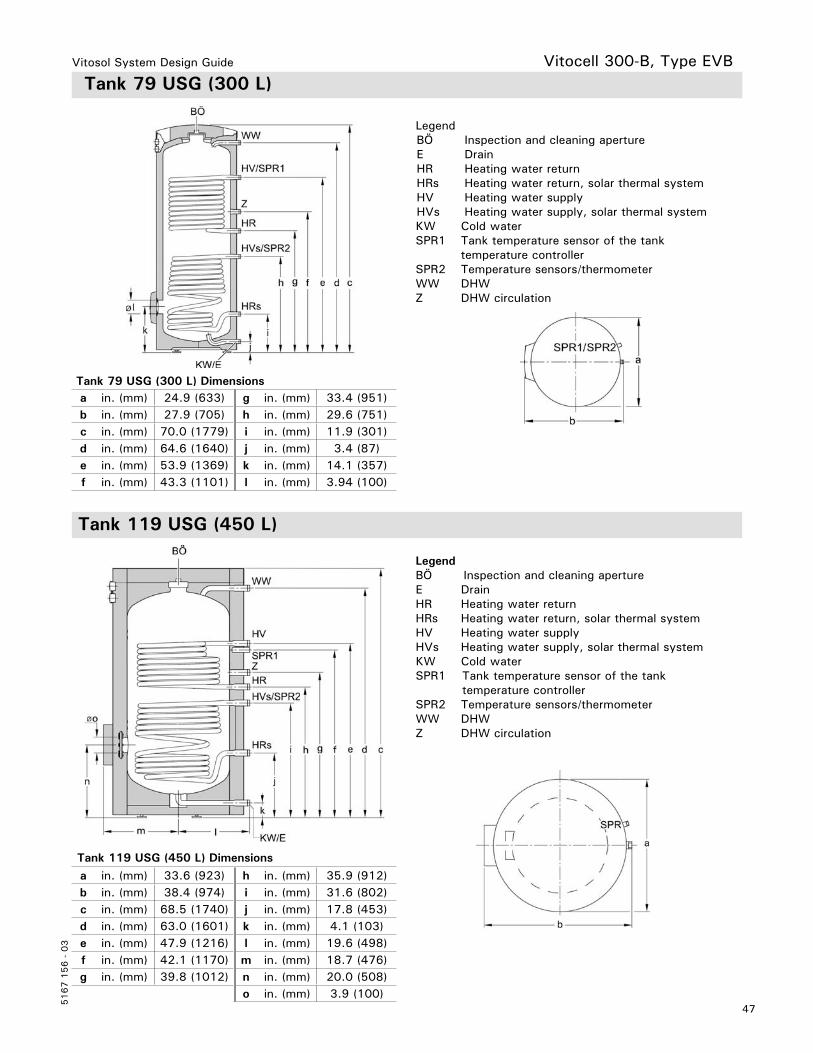
Vitosol System Design Guide
47
5167 1
56 -
03
Vitocell 300-B, Type EVB Tank 79 USG (300 L)
LegendBÖ Inspection and cleaning apertureE DrainHR Heating water returnHRs Heating water return, solar thermal systemHV Heating water supplyHVs Heating water supply, solar thermal systemKW Cold waterSPR1 Tank temperature sensor of the tank temperature controllerSPR2 Temperature sensors/thermometerWW DHWZ DHW circulation
Tank 79 USG (300 L) Dimensionsa in. (mm) 24.9 (633) g in. (mm) 33.4 (951)b in. (mm) 27.9 (705) h in. (mm) 29.6 (751)c in. (mm) 70.0 (1779) i in. (mm) 11.9 (301)d in. (mm) 64.6 (1640) j in. (mm) 3.4 (87)e in. (mm) 53.9 (1369) k in. (mm) 14.1 (357)f in. (mm) 43.3 (1101) l in. (mm) 3.94 (100)
Tank 119 USG (450 L) Dimensions
a in. (mm) 33.6 (923) h in. (mm) 35.9 (912)b in. (mm) 38.4 (974) i in. (mm) 31.6 (802)c in. (mm) 68.5 (1740) j in. (mm) 17.8 (453)d in. (mm) 63.0 (1601) k in. (mm) 4.1 (103)e in. (mm) 47.9 (1216) l in. (mm) 19.6 (498)f in. (mm) 42.1 (1170) m in. (mm) 18.7 (476)g in. (mm) 39.8 (1012) n in. (mm) 20.0 (508)
o in. (mm) 3.9 (100)
BÖ Inspection and cleaning apertureE DrainHR Heating water returnHRs Heating water return, solar thermal systemHV Heating water supplyHVs Heating water supply, solar thermal systemKW Cold waterSPR1 Tank temperature sensor of the tank temperature controllerSPR2 Temperature sensors/thermometerWW DHWZ DHW circulation
Legend
Tank 119 USG (450 L)
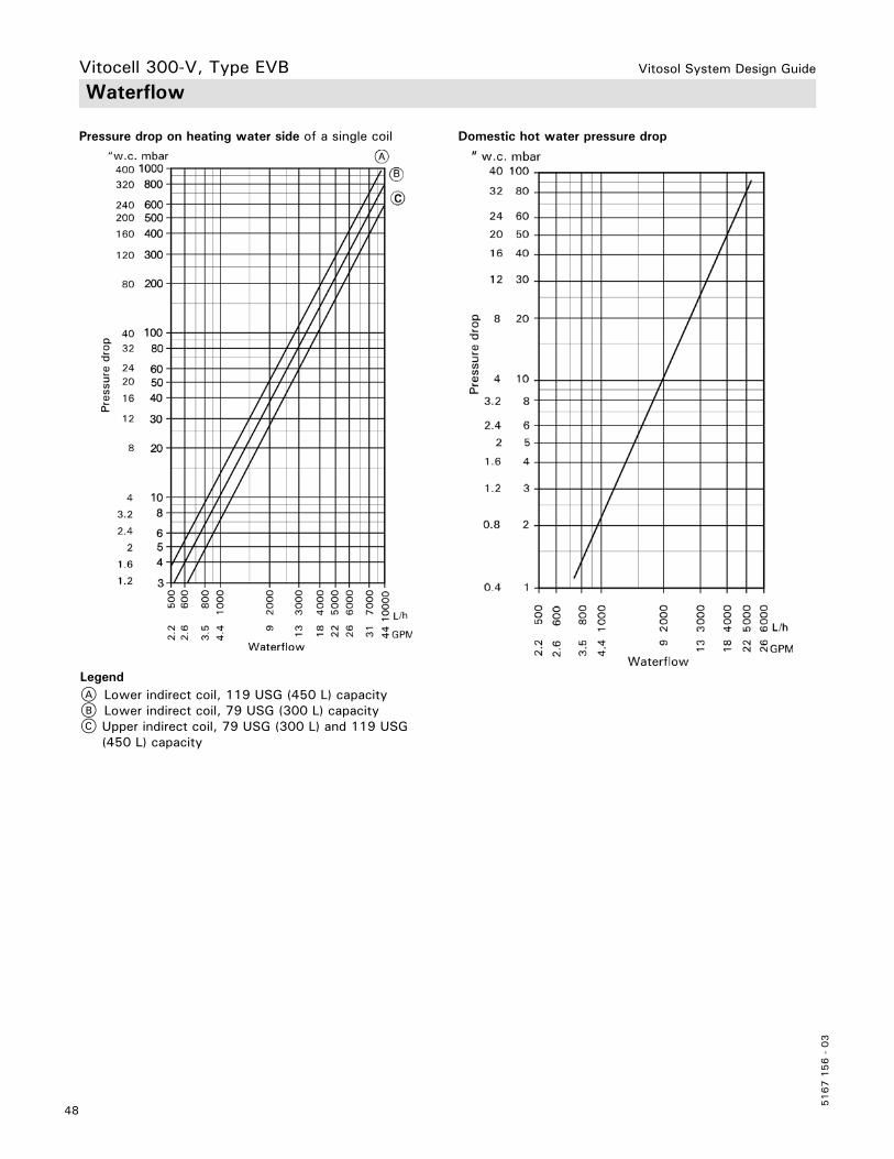
Vitosol System Design Guide
5167 1
56 -
03
48
Pressure drop on heating water side of a single coil Domestic hot water pressure drop
A Lower indirect coil, 119 USG (450 L) capacityB Lower indirect coil, 79 USG (300 L) capacityC Upper indirect coil, 79 USG (300 L) and 119 USG (450 L) capacity
WaterflowVitocell 300-V, Type EVB
Legend

Vitosol System Design Guide
49
5167 1
56 -
03
Technical Data
Storage Capacity USG(L)
42(160)
53(200)
79(300)
119(450)
Recovery rate with a temperature rise of the domestic hot water from 50 to 113°F (10 to 45°C) and boiler water supply temperature of.... at the supply flow rate stated below
194°F MBH(90°C) USG/min
(L/h)
1364.3
(982)
1364.3
(982)
1805.7
(1302)
2387.6
(1720)176°F MBH(80°C) USG/min
(L/h)
1093.5
(786)
1093.5
(786)
1504.8
(1081)
1986.3
(1425)158°F MBH(70°C) USG/min
(L/h)
852.7
(614)
852.7
(614)
1133.6
(811)
1534.9
(1106)140°F MBH(60°C) USG/min
(L/h)
581.8
(417)
581.8
(417)
780.3
(565)
1093.5
(786) 122°F MBH(50°C) USG/min
(L/h)
311
(221)
311
(221)
611.9
(442)
822.6
(589)Recovery rate*1 with a temperature rise of the domestic hot water from 50 to 140°F (10 to 60°C) and boiler water supply temperature of.... at the supply flow rate stated below
194°F MBH(90°C) USG/min
(L/h)
176°F MBH(80°C) USG/min
(L/h)
158°F MBH(70°C) USG/min
(L/h)
1232.7
(619)
952
(482)
651.4
(327)
1232.7619
952
(482)
651.4
(327)
1533.4774
1162.6
(584)
781.7
(395)
1814
(911)
1503.3
(756)
1132.5
(567)Supply flow rate for therecovery rates stated
USG/min(m3/h)
13.2(3.0)
13.2(3.0)
13.2(3.0)
13.2(3.0)
Standby losses *2 MBH/24 h(kw/24 h)
5.1(1.5)
5.8(1.7)
7.5(2.2)
9.6(2.8)
Overall dimensions with insulationWidth (∅)DepthHeightTilt height
in. (mm)in. (mm)in. (mm)in. (mm)
23 (581)24 (608)47 (1189)50 (1260)
23 (581)24 (608)
55½ (1409)57½ (1460)
25 (633)27¾ (705)68¾ (1746)70½ (1792)
33½ (850)35¼ (898)77 (1955)
73¼ (1860)WeightTank with insulation
lbs(kg)
190(86)
214(97)
333(151)
399(181)
Heating water content USG(L)
1.45(5.5)
1.45(5.5)
2.6(10)
3.3(12.5)
Heat exchanger surface area ft.2(m2)
10.8(1)
10.8(1)
16.1(1.5)
20.5(1.9)
ConnectionsHeating water supply/returnDomestic cold/hot waterT&P valveRecirculation
∅” (male thread)∅” (male thread)
∅” (female thread)∅” (male thread)
1¾ ¾¾
1¾¾¾
11¾1
11 ¾¾1
Suitable for the following systems:
H DHW temperatures up to 203°F (95°C)
H Heating water flow temperature up to 320°F (160°C)
H Operating pressure on the heating water side up to 25 bar (2.5 MPa)
H Operating pressure on the DHW side up to 10 bar (1.0 MPa)
Vitocell 100-V, Type CVA
*1 When planning for the recovery rate as stated or calculated, allow for the corresponding circulation pump. The stated recovery rate is only achieved when the rated output of the boiler is equal to or greater than that stated under “Recovery rate”. Please also refer to the corresponding sizing chart at the end of this manual.*2 Measured values are based on a room temp. of 68°F (20ºC) and a domestic hot water temp. of 149°F (65ºC) and can vary by 5%.
Corrosion protected steel tank with Ceraprotect two-coat enamel finish and magnesium anode.
For DHW production in conjunction with heating boilers,or with solar collectors in a solar preheating system.

Vitosol System Design Guide
5167 1
56 -
03
50
Tank 42 and 53 USG (160 and 200 L)
BÖ Inspection and cleaning apertureE DrainHR Heating water returnHV Heating water supplyKW Cold waterSPR Tank temperature sensor of the tank temperature controller or thermostatVA Protective magnesium anodeWW DHWZ DHW circulation
Vitocell 100-V, Type CVA
Legend
Tank 42 USG (160 L) Dimensions
a in. (mm) 22.8 (581) f in. (mm) 24.9 (634)
b in. (mm) 23.9 (608) g in. (mm) 9.8 (249)
c in. (mm) 46.8 (1189) h in. (mm) 2.8 (72)
d in. (mm) 41.3 (1050) i in. (mm) 12.5 (317)
e in. (mm) 34.8 (884) j in. (mm) 23.9 (608)
Tank 53 USG (200 L) Dimensions
a in. (mm) 24.9 (633) g in. (mm) 10.2 (260)
b in. (mm) 27.8 (705) h in. (mm) 3.0 (76)
c in. (mm) 68.7 (1746) i in. (mm) 13.5 (343)
d in. (mm) 63.0 (1600) j in. (mm) 27.8 (705)
e in. (mm) 43.9 (1115) k in. (mm) 13.1 (333)
f in. (mm) 34.4 (875) l in. (mm) 3.9 (100)

Vitosol System Design Guide
51
5167 1
56 -
03
Tank 79 USG (300 L)Vitocell 100-V, Type CVA
BÖ Inspection and cleaning apertureE DrainHR Heating water returnHV Heating water supplyKW Cold waterSPR Tank temperature sensor of the tank temperature controller or thermostatVA Protective magnesium anodeWW DHWZ DHW circulation
Legend
Tank 79 USG (300 L) Dimensions
a in. (mm) 24.9 (633) h in. (mm) 3.0 (76)
b in. (mm) 27.7 (705) i in. (mm) 13.5 (343)
c in. (mm) 68.7 (1746) j in. (mm) 3.9 ( 100)
d in. (mm) 63 (1600) k in. (mm) 27.7 (705)
e in. (mm) 43.9 (1115) l in. (mm) 13.1 (333)
f in. (mm) 34.4 (875) m in. (mm) 3.9 (100)
g in. (mm) 10.2 (260)
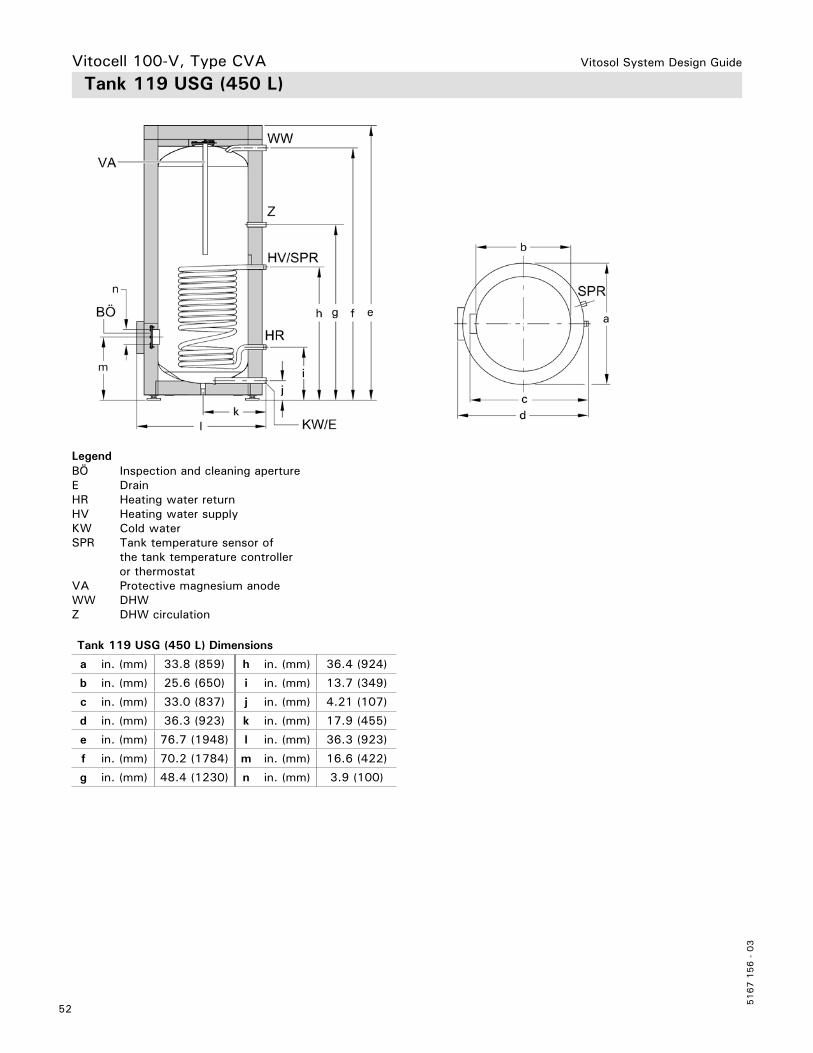
Vitosol System Design Guide
5167 1
56 -
03
52
Vitocell 100-V, Type CVA Tank 119 USG (450 L)
BÖ Inspection and cleaning apertureE DrainHR Heating water returnHV Heating water supplyKW Cold waterSPR Tank temperature sensor of the tank temperature controller or thermostatVA Protective magnesium anodeWW DHWZ DHW circulation
Legend
Tank 119 USG (450 L) Dimensions
a in. (mm) 33.8 (859) h in. (mm) 36.4 (924)
b in. (mm) 25.6 (650) i in. (mm) 13.7 (349)
c in. (mm) 33.0 (837) j in. (mm) 4.21 (107)
d in. (mm) 36.3 (923) k in. (mm) 17.9 (455)
e in. (mm) 76.7 (1948) l in. (mm) 36.3 (923)
f in. (mm) 70.2 (1784) m in. (mm) 16.6 (422)
g in. (mm) 48.4 (1230) n in. (mm) 3.9 (100)
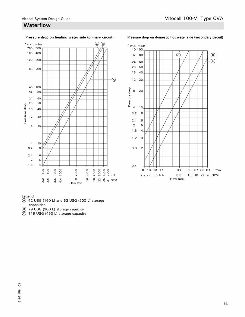
Vitosol System Design Guide
53
5167 1
56 -
03
Waterflow
Pressure drop on heating water side (primary circuit) Pressure drop on domestic hot water side (secondary circuit)
A 42 USG (160 L) and 53 USG (200 L) storage capacitiesB 79 USG (300 L) storage capacityC 119 USG (450 L) storage capacity
Vitocell 100-V, Type CVA
Legend

Vitosol System Design Guide
5167 1
56 -
03
54
Storage Capacity USG(L)
53(200)
79(300)
119(450)
Recovery rate *1 with a temperature rise of the domestic hot 50 to 113°F (10 to 45°C)
194°F MBH(90°C) USG/min
(L/h)
2154.7
(1084)
2806.2
(1410)
2766.1
(1393)
and boiler water supplytemperature of.... at thesupply flow rate statedbelow
176°F MBH(80°C) USG/min
(L/h)
1643.6
(826)
2014.5
(1014)
2124.7
(1066)
158°F MBH(70°C) USG/min
(L/h)
992.1
(499)
1403.1
(705)
1473.3
(739)Supply flow rate for the recovery rates stated
USG/min(m3/h)
22.0(5.0)
22.0(5.0)
28.6(6.5)
Supply flow rate for therecovery rates stated
USG/min(m3/h)
13.2(3.0)
25(3.0)
13.2(3.0)
Standby losses *2 MBH/24 h(kw/24 h)
5.5(1.6)
6.8(2.0)
9.2(2.7)
Overall dimensions with insulation Overall width
Overall depth
Overall height
Tilt height
*3in.
(mm)in.
(mm)in.
(mm)in.
(mm)
22 7/8(581)25½(649)56
(1420)58
(1471)
25(633)27¾(704)70
(1779)71¾
(1821)
36½(923)38e(974)68½
(1740)66½
(1690)WeightTank with insulation
lbs(kg)
168(76)
220(100)
245(111)
Heating water content(heat exchanger pipe coil)
USG(L)
2.64(10)
2.91(11)
4.0(15.0)
Heat exchanger surface area ft2(m2)
14(1.3)
16(1.5)
20.5(1.9)
ConnectionsHeating water supply/returnDomestic cold/hot waterTemp. and press. relief valveRecirculation
∅’’ (male thread) 1 ∅’’ (male thread) 1 ∅’’ (male thread) 1 ∅’’ (male thread) 1
1111
1¼1¼1¼1¼
Technical DataVitocell 300-V, Type EVI
*1 When planning for the recovery rate as stated or calculated, allow for the corresponding circulation pump. The stated recovery rate is only achieved when the rated output of the boiler is equal to or greater than that stated under “Recovery rates”. Please also refer to the corresponding sizing chart at the end of this manual.*2 Measured values are based on a room temperature of 68ºF (20ºC) and a domestic hot water temperature of 149ºF (65ºC) and can vary by ±5%.
For information regarding other Viessmann System Technology componentry, please reference documentation of the respective product.
H max. working pressure on heat exchanger side up to 220 psig at 392°F (200°C)
H max. working pressure on DHW water side of up to 150 psig at 210°F (99°C)
Corrosion resistant tank and coils made of high-grade SA 240-316 Ti stainless steel.
For DHW heating in conjunction with boilers or with solar collectors in a solar preheating system.

Vitosol System Design Guide
55
5167 1
56 -
03
Tank 53 and 79 USG (200 and 300 L)
BÖ Inspection and cleaning apertureE DrainHR Heating water returnHV Heating water supplyKW Cold waterR Additional cleaning aperture SPR Tank temperature sensor of the tank temperature controller or thermostat (connector R1 with reducer to R ½ for sensor well)WW DHWZ DHW circulation
Vitocell 300-V, Type EVI
Legend
Tank 53 USG (200 L) Dimensions
a in. (mm) 22.8 (581) g in. (mm) 27.4 (697)
b in. (mm) 24.2 (614) h in. (mm) 11.7 (297)
c in. (mm) 25.6 (649) i in. (mm) 3.4 (87)
d in. (mm) 55.9 (1420) j in. (mm) 12.5 (317)
e in. (mm) 50.6 (1286) k in. (mm) 13.9 (353)
f in. (mm) 35.3 (897) l in. (mm) 3.9 (100)
Tank 79 USG (300 L) Dimensions
a in. (mm) 24.9 (633) g in. (mm) 29.6 (751)
b in. (mm) 26.2 (665) h in. (mm) 11.9 (301)
c in. (mm) 27.7 (704) i in. (mm) 3.4 (87)
d in. (mm) 70.0 (1779) j in. (mm) 13.5 (343)
e in. (mm) 64.6 (1640) k in. (mm) 14.1 (357)
f in. (mm) 37.4 (951) l in. (mm) 3.9 (100)

Vitosol System Design Guide
5167 1
56 -
03
56
Tank 119 USG (450 L)
BÖ Inspection and cleaning apertureE DrainHR Heating water returnHV Heating water supplyKW Cold waterR Additional cleaning aperture SPR Tank temperature sensor of the tank temperature controller or thermostat (connector R1 with reducer to R ½ for sensor well)WW DHWZ DHW circulation
Vitocell 300-V, Type EVI
Legend
Tank 119 USG (450 L) Dimensions
a in. (mm) 36.4 (925) h in. (mm) 39.9 (1012)
b in. (mm) 28.1 (715) i in. (mm) 31.6 (802)
c in. (mm) 35.9 (914) j in. (mm) 17.8 (453)
d in. (mm) 38.4 (975) k in. (mm) 4.0 (102)
e in. (mm) 68.4 (1738) l in. (mm) 19.6 (498)
f in. (mm) 65.6 (1667) m in. (mm) 18.7 (476)
g in. (mm) 63.0 (1601) n in. (mm) 20.0 (508)
o in. (mm) 3.9 (100)
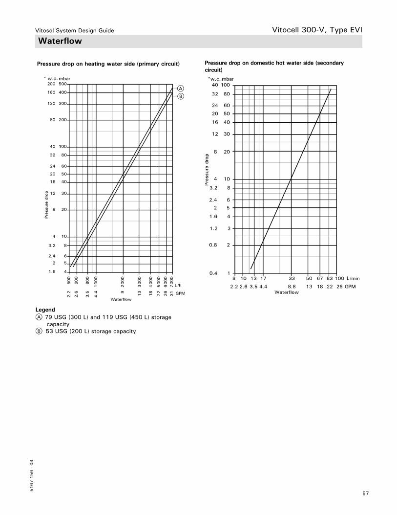
Vitosol System Design Guide
57
5167 1
56 -
03
Waterflow
Pressure drop on heating water side (primary circuit)
A 79 USG (300 L) and 119 USG (450 L) storage capacityB 53 USG (200 L) storage capacity
Pressure drop on domestic hot water side (secondary circuit)
Vitocell 300-V, Type EVI
Legend
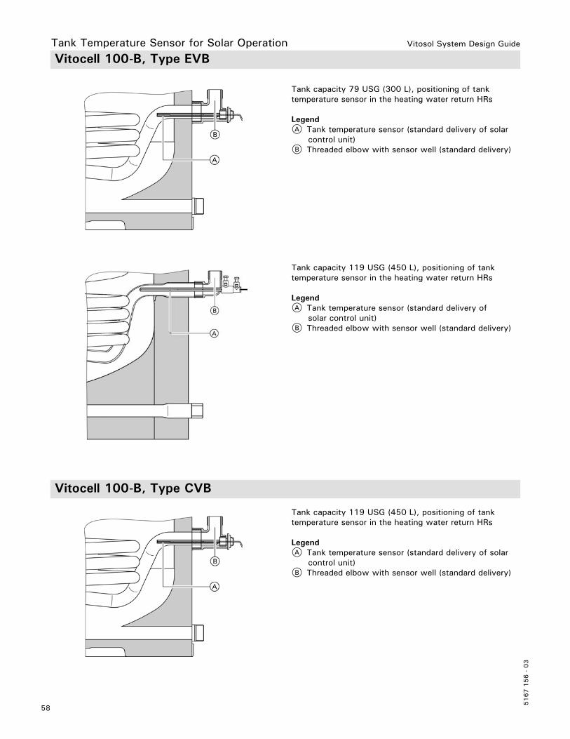
Vitosol System Design Guide
5167 1
56 -
03
58
Tank capacity 79 USG (300 L), positioning of tank temperature sensor in the heating water return HRs
LegendA Tank temperature sensor (standard delivery of solar control unit)B Threaded elbow with sensor well (standard delivery)
Tank capacity 119 USG (450 L), positioning of tank temperature sensor in the heating water return HRs
LegendA Tank temperature sensor (standard delivery of solar control unit)B Threaded elbow with sensor well (standard delivery)
Tank capacity 119 USG (450 L), positioning of tank temperature sensor in the heating water return HRs
LegendA Tank temperature sensor (standard delivery of solar control unit)B Threaded elbow with sensor well (standard delivery)
Tank Temperature Sensor for Solar Operation Vitocell 100-B, Type EVB
Vitocell 100-B, Type CVB
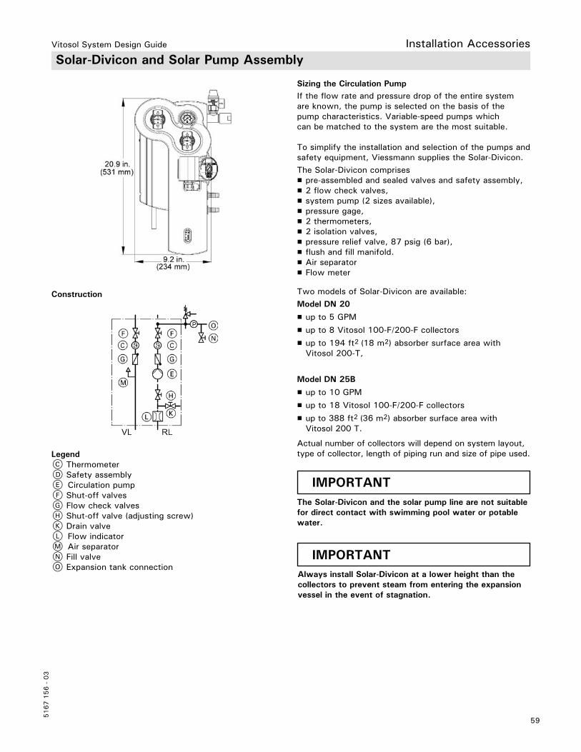
Vitosol System Design Guide
59
5167 1
56 -
03
Solar-Divicon and Solar Pump Assembly
If the flow rate and pressure drop of the entire system are known, the pump is selected on the basis of the pump characteristics. Variable-speed pumps which can be matched to the system are the most suitable.
To simplify the installation and selection of the pumps and safety equipment, Viessmann supplies the Solar-Divicon.The Solar-Divicon comprises H pre-assembled and sealed valves and safety assembly, H 2 flow check valves, H system pump (2 sizes available), H pressure gage, H 2 thermometers, H 2 isolation valves, H pressure relief valve, 87 psig (6 bar), H flush and fill manifold. H Air separator H Flow meter
Two models of Solar-Divicon are available:Model DN 20
H up to 5 GPM
H up to 8 Vitosol 100-F/200-F collectors
H up to 194 ft2 (18 m2) absorber surface area with Vitosol 200-T,
Model DN 25B
H up to 10 GPM
H up to 18 Vitosol 100-F/200-F collectors
H up to 388 ft2 (36 m2) absorber surface area with Vitosol 200 T.
Actual number of collectors will depend on system layout, type of collector, length of piping run and size of pipe used.
IMPORTANT
IMPORTANT
The Solar-Divicon and the solar pump line are not suitable for direct contact with swimming pool water or potablewater.
Always install Solar-Divicon at a lower height than the collectors to prevent steam from entering the expansionvessel in the event of stagnation.
Installation Accessories
Construction
C ThermometerD Safety assemblyE Circulation pumpF Shut-off valvesG Flow check valvesH Shut-off valve (adjusting screw)K Drain valveL Flow indicatorM Air separatorN Fill valveO Expansion tank connection
Legend
Sizing the Circulation Pump

Vitosol System Design Guide
5167 1
56 -
03
60
Specification
Brass flow check valves: Located in each supply and return lines. Open manually by turning thermometer handles.
Solar-Divicon Model DN 20 Model DN 25B
Circulation pump (Model: Wilo)Rated voltageMaximum flow rateMaximum headFlow meter (setting range)Safety relief valveMax. operating temperatureMax. operating pressureLiquid contentConnections (Compression fittings Ø)Solar circuitSolar expansion tankSafety relief valve
VUSG/min (L/min)
ft. (m)USG/min (L/min)
psig (bar)°F (°C)
psig (bar)USG (L)
in. in. in.
STAR S 16 U 15AC 1157 (26.5)20 (6.1)
0.5 to 5 (1 to 20)87 (6)
248 (120)87 (6)
0.13 (0.4)
½½½
STAR S 30 U 25AC 115
12 (45.5)29 (8.8)
1 to 10 (5 to 40)87 (6)
248 (120)87 (6)
0.2 (0.75
1¾¾
Pump Curves
Installation Accessories
Model DN 20
Model DN 25B

Vitosol System Design Guide
61
5167 1
56 -
03
Manual Air Vent Valve
Locking ring fitting with manual air vent valve. For installation at the highest point of the system.Can be used as an alternative to a fast acting air vent.
Installation in the supply pipe of the solar circuit, preferably upstream of the inlet into the DHW tank.
Install at the highest point of the system. With shut-off valve and locking ring fitting. Install 1 fast acting air vent valve in each collector array
Stainless steel corrugated pipes with thermal insulation and protective foil, locking ring fittings and sensor wire.
Available in three coil sizes:– 20 ft. (6 m) long– 40 ft. (12 m) long– 50 ft. (15 m) long
Installation Accessories
Air Separator
Fast-acting Air Vent Valve (with shut-off)
Flexible Insulated Piping
For use in small scale solar systems with <10 m2/108 ft2collector absorber area. Refer to pressure drop chart on pages 97 and 98.
IMPORTANTShut-off valve must be closed after initial system commissioning. Failure to close will result in glycol steaming off during stagnation.

Vitosol System Design Guide
5167 1
56 -
03
62
Slice Kit for Insulated Piping
For splicing together stainless steel piping:– 2 pipe sleeves– 8 O-rings– 4 support rings– 4 profile clips
For joining the stainless steel piping to the pipework of the solar thermal system:– 2 pipe sleeves with locking ring fitting– 4 O-rings– 2 support rings– 2 profile clips
For topping-up and raising the pressure of the solar fluid.Connects to Solar-Divicon pumping station.
Connection Set with Locking Ring Fitting
Manual Solar Fill Pump
Installation Accessories
Mobile Solar Charge Station
For flushing and filling of solar systems:– telescopic handle– 120VAC, 5 bar (75 psig), 8 USGPM (30 L/m)– dirt and debris filter on suction side– 1 charge hose, 1 suction hose– 8 USG (30 L) storage tank for glycol

Vitosol System Design Guide
63
5167 1
56 -
03
Installation Accessories Solar Expansion Vessel
Layout and functionA solar expansion vessel is a sealed unvented vessel where the gas space (nitrogen charge) is separated from the space containing liquid (heat transfer medium) by a diaphragm; the pre-charge pressure is subject to the system height.
A Heat transfer mediumB Nitrogen chargeC Nitrogen bufferD Minimum safety seal 0.8 USG (3 L)E Safety sealF Delivered condition [pre-charge pressure 3 bar (0.3 MPa)]G Solar thermal system charged without heat effecting the systemH At maximum pressure and the highest heat transfer medium temperature
Expansion vessel Capacity USG (L) Ø a in. (Ø a mm) b in. (b mm) Connection Weight lb. (kg)
A 4.75 (18)6.6 (25)10.6 (40)
11.0 (280)11.0 (280)13.9 (354)
14.96 (380)19.65 (499)20.5 (520)
R¾R¾R¾
16.5 (7.5) 20.0 (9.1)21.8 (9.9)
B 13.2 (50)21.1 (80)
16.1 (409)18.9 (480)
19.9 (505)22.3 (566)
R1R1
27.1 (12.3)40.5 (18.4)
Notes on the expansion tank
H The solar heating system must be equipped with a high temperature or solar rated membrane pressure expansion tank.
H Should the expansion tank be installed at the same level or higher than the Solar-Divicon, a heat insulating loop (p-trap) is required to prevent steam from entering the expansion tank.
H The membrane and gaskets of the expansion tank must be suitable for the heat transfer medium, and for the high temperature in a solar system.
H Adjust air cushion pressure of the expansion tank to cold fill pressure calculated for the system; for information regarding the calculation of the cold fill pressure value refer to the Vitosol Start-up, Service and Operating Instructions for information on setting the system and expansion tank pressures.
For expansion tank sizing refer to page 104.
Legend
Solar Expansion Vessel Specification H Maximum temperature 248ºF (120ºC)
H Maximum pressure 150 psig (10 bar)
H Suitable for glycol concentrations up to 50%
H Expansion vessels are supplied with a service valve c/w check valve and drain valve. This allows vessel charge pressure to be checked during servicing.

Vitosol System Design Guide
5167 1
56 -
03
64
Snow Load and Wind Load Zones
The collectors and the fixing system must be designed in such a way that they can withstand any snow and wind loads that may occur.
Observe the following for installation on pitched roofs:
– If the distance from the top edge of the collector array to the ridge of the roof is greater than 3.3 ft. (1 m), we recommend installing a snow guard.
– Never install collectors close to roof overhangs where snow is likely to slide off. If necessary, install a snow guard.
Note: The additional loads due to accumulated snow on collectors or snow guards must be taken into account in the structural calculations for the building.
Connect the solar circuit pipework with an electrical conductor (grounding cable) in the lower part of the building in accordance with local regulations. The integration of the collector system into a new or existing lightning protection facility or the provision of local earthing must only be carried out by authorized personnel, who should take the site conditions into account.
Certain parts of the roof are subject to special requirements. Allow for increased wind turbulence in these areas:– Corner area A: limited on two sides by the end of the roof– Edge area B: limited on one side by the end of the roof
The width of A and B should never be less then 3.3 ft.(1 m) with 6.6 ft. (2 m) preferred. Check with local codes to verify distance required in your area.
Distance from the Edge of the Roof
Routing Pipe Work
During the design phase, ensure the pipes are installed descending from the collector. This ensures better steam expulsion characteristics in the solar thermal system as a whole in the event of stagnation. The thermal load exerted on all system components is reduced (see page 102).
Equipotential Bonding/Lightning Protection of the Solar Thermal System
Design Information

Vitosol System Design Guide
65
5167 1
56 -
03
Design Information
H The thermal insulation material provided must withstand the operating temperatures to be expected and must be permanently protected against the influence of moisture. Some open pore insulation material that can be subjected to high thermal loads cannot provide reliable protection against moisture produced by condensation. The high temperature versions of closed-cell insulating hoses, on the other hand, offer adequate protection against moisture, but cannot be loaded with temperatures higher than approx. 338°F (170°C). However, the connections at the collector can be subjected to temperatures of up to 392°F (200°C) (flat-plate collector); for vacuum tube collectors, these temperatures can be substantially higher 557ºF (292ºC). At temperatures of over 338°F (170°C), the insulation material becomes brittle. However, the brittle zone is limited to a few millimeters directly contacting the pipe. This overload only occurs for a short period and does not pose any further risk to other components.
H The thermal insulation of the solar lines routed outdoors must be protected against pecking damage from birds and gnawing by small animals, as well as against UV radiation. A cover protecting the insulation against damage by small animals (e.g. metal sheath) generally also provides adequate UV protection.
LegendA 16.4 ft. (5 m) pipe lengthB 9.8 ft. (3 m) pipe lengthC 3.3 ft. (1 m) pipe length
H Use stainless steel pipe or commercially available copper pipe and bronze fittings.
H Metal seals (conical or locking rings and compression fittings) are suitable for solar lines. If other seals such as flat gaskets are used, adequate glycol, pressure and temperature stability must be guaranteed by the manufacturer.
H Never use: – Teflon (inadequate glycol stability) – Hemp connections (not sufficiently gas-tight)
H Generally, copper lines in solar circuits are hard soldered or joined by press fittings. Soft solder or low temperature solder could be weakened, particularly near the collectors, due to the max. temperatures that may occur there. Metal seal connections, locking ring fittings or Viessmann plug-in connections with double O-rings are the most suitable.
H All components to be used must be resistant to the heat transfer medium.
Note: Fill solar thermal systems only with Viessmann “Tyfocor” or similar non-toxic heat transfer medium.
H Take high temperature differentials in the solar circuit into consideration when routing and securing pipes.
At pipe sections that may be subject to steam loads, temperature differentials of up to 360°Ra (200°K) can be expected, otherwise 216°Ra (120°K) can be expected.
H Route the solar connection lines through a suitable roof flashing.
Thermal Insulation
Solar Supply and Return Lines
Thermal Expansion of Copper
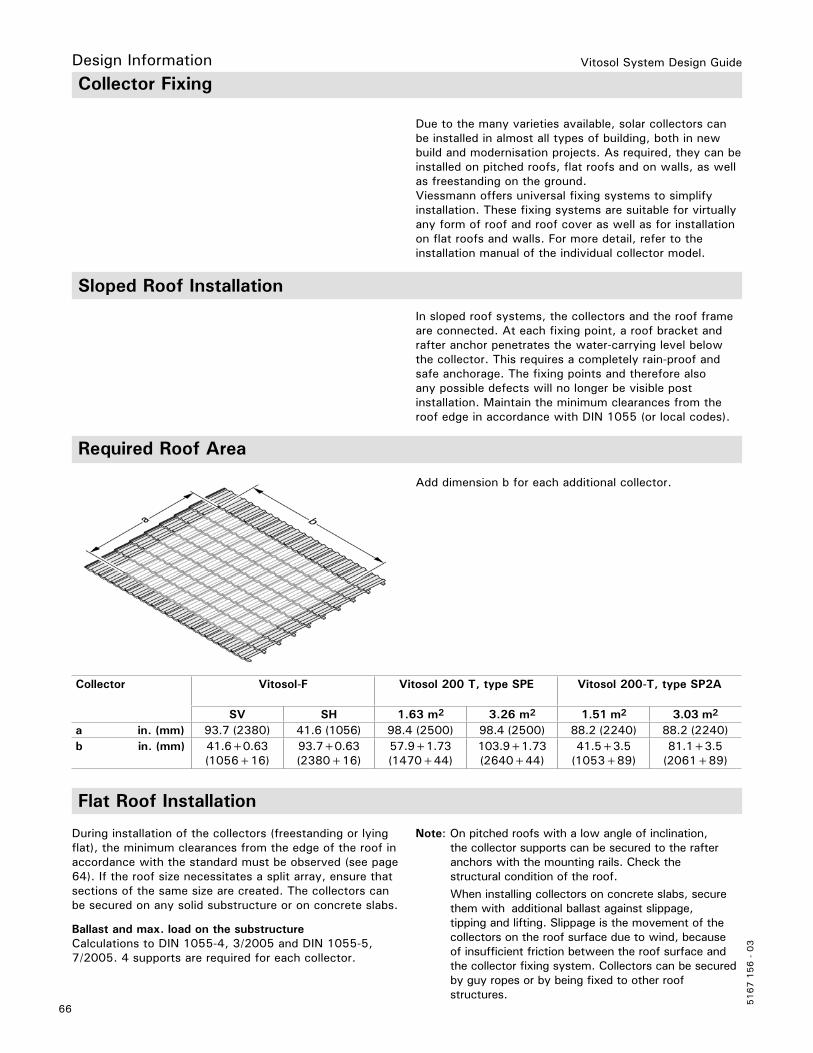
Vitosol System Design Guide
5167 1
56 -
03
66
In sloped roof systems, the collectors and the roof frame are connected. At each fixing point, a roof bracket and rafter anchor penetrates the water-carrying level below the collector. This requires a completely rain-proof and safe anchorage. The fixing points and therefore alsoany possible defects will no longer be visible post installation. Maintain the minimum clearances from the roof edge in accordance with DIN 1055 (or local codes).
Collector Vitosol-F Vitosol 200 T, type SPE Vitosol 200-T, type SP2A
SV SH 1.63 m2 3.26 m2 1.51 m2 3.03 m2
a in. (mm) 93.7 (2380) 41.6 (1056) 98.4 (2500) 98.4 (2500) 88.2 (2240) 88.2 (2240)b in. (mm) 41.6+0.63
(1056+16)93.7+0.63(2380+16)
57.9+1.73(1470+44)
103.9+1.73(2640+44)
41.5+3.5(1053+89)
81.1+3.5(2061+89)
Collector Fixing
Due to the many varieties available, solar collectors can be installed in almost all types of building, both in new build and modernisation projects. As required, they can be installed on pitched roofs, flat roofs and on walls, as well as freestanding on the ground.Viessmann offers universal fixing systems to simplify installation. These fixing systems are suitable for virtually any form of roof and roof cover as well as for installation on flat roofs and walls. For more detail, refer to the installation manual of the individual collector model.
Sloped Roof Installation
Required Roof Area
Add dimension b for each additional collector.
Flat Roof Installation
During installation of the collectors (freestanding or lying flat), the minimum clearances from the edge of the roof in accordance with the standard must be observed (see page 64). If the roof size necessitates a split array, ensure that sections of the same size are created. The collectors can be secured on any solid substructure or on concrete slabs.
Note: On pitched roofs with a low angle of inclination, the collector supports can be secured to the rafter anchors with the mounting rails. Check the structural condition of the roof. When installing collectors on concrete slabs, secure them with additional ballast against slippage, tipping and lifting. Slippage is the movement of the collectors on the roof surface due to wind, because of insufficient friction between the roof surface and the collector fixing system. Collectors can be secured by guy ropes or by being fixed to other roof structures.
Ballast and max. load on the substructureCalculations to DIN 1055-4, 3/2005 and DIN 1055-5, 7/2005. 4 supports are required for each collector.
Design Information

Vitosol System Design Guide
67
5167 1
56 -
03
Design Information Installation on a Wall
Technical Building RegulationsFor the rules regarding the implementation of solar thermal systems, contact your local building department or refer to the local building code governing your jurisdiction. This includes flat-plate and tube collectors. These concern primarily the protection of pedestrian and traffic areas against falling glass.
Overhead glazingGlazing with an angle of inclination greater than 10°– No additional safety measures to protect against falling glass parts are required for flat-plate and tube collectors with an angle of inclination greater than 10°.
Vertical glazing Glazing with an angle of inclination smaller than 10°– The linear supported glazing (TRLV German regulations) does not apply to vertical glazing with an upper edge higher than max. 13.1 ft. (4 m) above a traffic area. No additional safety measures to protect against falling glass parts are required for flat-plate and tube collectors with an angle of inclination less than 10°.– For vertical glazing with an upper edge higher than 13.1 ft. (4 m) above a traffic area, suitable measures must be taken to effectively prevent glass from falling (e.g. netting or trays below; see the following diagrams).
Note: In North America check with local code requirements for wall mount installations
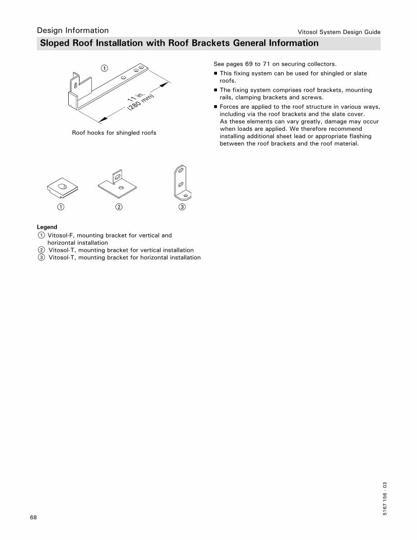
Vitosol System Design Guide
5167 1
56 -
03
68
Sloped Roof Installation with Roof Brackets General Information
See pages 69 to 71 on securing collectors.
H This fixing system can be used for shingled or slate roofs.
H The fixing system comprises roof brackets, mounting rails, clamping brackets and screws.
H Forces are applied to the roof structure in various ways, including via the roof brackets and the slate cover. As these elements can vary greatly, damage may occur when loads are applied. We therefore recommend installing additional sheet lead or appropriate flashing between the roof brackets and the roof material.
Roof hooks for shingled roofs
1 Vitosol-F, mounting bracket for vertical and horizontal installation2 Vitosol-T, mounting bracket for vertical installation3 Vitosol-T, mounting bracket for horizontal installation
Legend
Design Information

Vitosol System Design Guide
69
5167 1
56 -
03
Design Information Slope Roof Installations for Vitosol 100-F/200-F Flat Plate Collectors
A CollectorB Lag boltC Mounting railD Roof bracket
Collector Dimension a b c
Model SV1/SV2
Model SH1/SH2
in.(mm)
in.(mm)
93.7(2380)41.8
(1056)
74.7 - 82.5(1900 - 2100)17.7 - 33.5(450 - 850)
3.5(89)3.5(89)
Legend
Refer to the Vitosol-F Installation Instructions for all mounting hardware dimensions and detailed installation instruction

Vitosol System Design Guide
5167 1
56 -
03
70
Legend A Header casingB Mounting railC Tube retainerD Mounting bracketE Roof bracketF Vacuum tube
Legend A Vacuum tubeB Clamping bracketC Tube retainerD Mounting railE Roof bracketF Header casingG Mounting plate
Horizontal installation
Vertical installation
Refer to the Vitosol 200-T, SP2A Installation Instructions for all mounting hardware dimensions and detailed installation instructions.
Slope Roof Installations for Vitosol 200-T, SP2A Vacuum Tube CollectorsDesign Information

Vitosol System Design Guide
71
5167 1
56 -
03
Design Information
Legend A Header casingB Mounting railC Tube retainerD Mounting bracketE Roof bracketF Vacuum tube
Legend A Vacuum tubeB Clamping bracketC Tube retainerD Mounting railE Roof bracketF Header casingG Mounting plate
Horizontal installation
Vertical installation
Slope Roof Installations for Vitosol 200-T, SPE Vacuum Tube Collectors
Refer to the Vitosol 200-T, SPE Installation Instructions for all mounting hardware dimensions and detailed installation instructions.
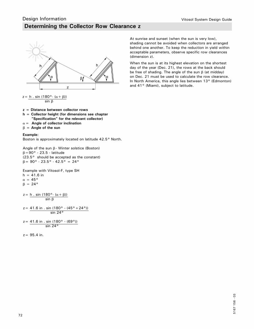
Vitosol System Design Guide
5167 1
56 -
03
72
Determining the Collector Row Clearance z
At sunrise and sunset (when the sun is very low), shading cannot be avoided when collectors are arranged behind one another. To keep the reduction in yield within acceptable parameters, observe specific row clearances (dimension z).
When the sun is at its highest elevation on the shortest day of the year (Dec. 21), the rows at the back should be free of shading. The angle of the sun β (at midday) on Dec. 21 must be used to calculate the row clearance.In North America, this angle lies between 13° (Edmonton) and 41° (Miami), subject to latitude.
z = Distance between collector rowsh = Collector height (for dimensions see chapter “Specification” for the relevant collector)α = Angle of collector inclinationβ = Angle of the sun
Design Information
z= h . sin (180°- (α+ β)) sin β
z= 41.6 in . sin (180° - (45°+24°)) sin 24°
z= 41.6 in . sin (180° - (69°)) sin 24°
z= 95.4 in.
Example:Boston is approximately located on latitude 42.5° North.
Angle of the sun β - Winter solstice (Boston)β=90° - 23.5 - latitude(23.5° should be accepted as the constant)β= 90° - 23.5° - 42.5° = 24°
Example with Vitosol-F, type SHh = 41.6 inα = 45°β = 24°
z= h . sin (180°- (α+ β)) sin β

Vitosol System Design Guide
73
5167 1
56 -
03
Design Information
Viessmann offers adjustable collector supports for fixing the collectors:
— With a variable angle of inclination [snow loads up to 53.26 lb/ft2 (2.55 kN/m2), wind speeds up to 93.2 mph (150 km/h)]: The collector supports are pre-assembled. They consist of the base rail, collector support and adjustable support with holes for adjusting the angle of inclination (see the following chapter).
Collector supports with variable angle of inclination
Type SV — angle of inclination α 25 to 60°
A Base railB Adjustable supportC Collector support Base rail hole dimensions
A Base railB Adjustable supportC Collector support
Base rail hole dimensions
Type SH — angle of inclination α 25 to 45°
Vitosol-F Flat-Plate Collectors (on supports)
in. mm
a 3.1 80
b 3.9 100
c 0.4 11
d 2.0 50
e 63.0 1600
f 70.9 1800
g 3.9 100
in. mm
a 3.1 80
b 3.0 75
c 0.4 11
d 2.0 50
e 28.4 722
f 35.3 897
g 3.9 100
Legend
Legend
Refer to the Vitosol-F Installation Instructions for all mounting hardware dimensions and detailed installation instructions.

Vitosol System Design Guide
5167 1
56 -
03
74
Type SH — angle of inclination α 50 to 80°
A Base railB Adjustable supportC Collector support
Base rail hole dimensions
Type SV and SH — installation on an on-site substructure, e.g. steel beams
A Connecting braceB Connecting ties
Type SV SH
x in. (mm) 23.4 (595) 75.6 (1920)
y in. (mm) 18.9 (481) 18.9 (481)
z in. (mm) See page 72 See page 72
Flat Roof Installation
in. mm
a 3.1 80
b 3.0 75
c 0.4 11
d 2.0 50
e 28.4 722
f 35.3 897
g 3.9 100
Legend
Legend
Design Information
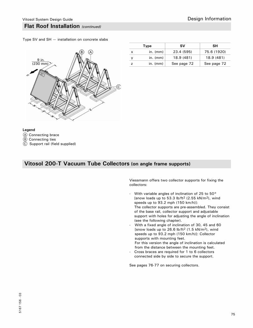
Vitosol System Design Guide
75
5167 1
56 -
03
Design Information
Type SV and SH — installation on concrete slabs
A Connecting braceB Connecting tiesC Support rail (field supplied)
Type SV SH
x in. (mm) 23.4 (595) 75.6 (1920)
y in. (mm) 18.9 (481) 18.9 (481)
z in. (mm) See page 72 See page 72
Viessmann offers two collector supports for fixing the collectors:
- With variable angles of inclination of 25 to 50° [snow loads up to 53.3 lb/ft2 (2.55 kN/m2), wind speeds up to 93.2 mph (150 km/h)]: The collector supports are pre-assembled. They consist of the base rail, collector support and adjustable support with holes for adjusting the angle of inclination (see the following chapter).- With a fixed angle of inclination of 30, 45 and 60 [snow loads up to 26.6 lb/ft2 (1.5 kN/m2), wind speeds up to 93.2 mph (150 km/h)]: Collector supports with mounting feet. For this version the angle of inclination is calculated from the distance between the mounting feet.- Cross braces are required for 1 to 6 collectors connected side by side to secure the support.
See pages 76-77 on securing collectors.
Flat Roof Installation (continued)
Legend
Vitosol 200-T Vacuum Tube Collectors (on angle frame supports)

Vitosol System Design Guide
5167 1
56 -
03
76
Collector Supports with Variable Angle of Inclination
A Base railB Adjustable supportC Collector support
For calculating distance z between collector rows, see page 72.
ASupport slab ABSupport slab B
Base rail hole dimensions
Vitosol 200-T, type SP2A
Combination a in. (mm) b in. (mm)
(1.51 m2/1.51 m2) 20/20 (505/505) 23.5 (595)
(1.51 m2/3.03 m2) 20/40 (505/1010) 33.5 (850)
(3.03 m2/3.03 m2) 40/40 (1010/1010) 43.5 (1100)
in. mm
a 3.1 80
b 3.9 100
c 0.4 11
d 2.0 50
e 78.7 2000
f 86.6 2200
g 3.9 100
Legend
Legend
Design Information

Vitosol System Design Guide
77
5167 1
56 -
03
Design Information
Angle of inclination 30° 45° 60°
c in. (mm)
95 (2413)
86.6 (2200)
72.4 (1838)
For calculating distance z between collector rows, see page 72.
Combination a in. (mm)
b in. (mm)
(1.63 m2/1.63 m2) 23.6/23.6 (600/600)
25.4 (644)
(1.63 m2/3.26 m2) 23.6/47.2 (600/1200)
37.4 (949)
(3.26 m2/3.26 m2) 47.2/47.2 (1200/1200)
48.6 (1234)
Vitosol 200-T, type SPE
A Support slab AB Support slab B
Legend
A Mounting footB Adjustable supportC Collector support
Legend
Collector Supports with Fixed Angle of Inclination
Vitosol 200-T, type SP2A
Combination a in. (mm)
b in. (mm)
(1.51 m2/1.51 m2) 20/20 (505/505)
23.5 (595)
(1.51 m2/3.03 m2) 20/40 (505/1010)
33.5 (850)
(3.03 m2/3.03 m2) 40/40 (1010/1010)
43.5 (1100)

Vitosol System Design Guide
5167 1
56 -
03
78
H Type SPE The yield can be optimized by rotating the vacuum tubes 45° to the horizontal.
This installation method allows for collectors SP2A and SPE to be mounted on a flat roof with tubes parallel to the roof and can be used for any application. Ballast weights are typically used to hold the collectors in place, however collectors can also be mounted to substructural frames.Align the collector panel with the absorbers facing south and with the tubes mounted in an east-west direction.Maximum tube rotation to avoid shading is 25° for the SP2A and 45° for the SPE. This limits the absorber plate angle of inclination range from 0° to 25° for the SP2A and 0° to 45° for the SPE.
The header must always be the highest point of the collector. The collector can function if the collector slope is 0° or higher, but the header must never be lower than the tube ends. Viessmann mounting hardware incorporates special mounting clips to ensure the header is the highest point of the collector.
A Support slab AB Support slab B
Legend
Vitosol 200-T Vacuum Tube Collectors Laid Flat with Tubes Horizontal
Vitosol 200-T, Type SP2A Tube Rotation Angle
Vitosol 200-T, Type SPE Tube Rotation Angle
H Type SP2A The yield can be optimized by rotating the vacuum tubes 25° to the horizontal.
Design Information

Vitosol System Design Guide
79
5167 1
56 -
03
Design Information
The collector supports are pre-assembled. They consist of a base rail, a collector support and adjustable supports. The adjustable supports contain holes for adjusting the angle of inclination.The fixing materials, e.g. wall attachment, screws, are to be provided on site.
Collector supports – angle Y 10 to 45°
A Base railB Adjustable supportC Collector supportD Wall
Base rail hole dimensions
Vitosol-F Flat-Plate Collectors, Type SH (wall mounting)
in. mm
a 3.1 80
b 3.0 75
c 0.4 11
d 2.0 50
e 28.4 722
f 35.3 897
g 3.9 100Legend
Refer to the Vitosol-F Installation Instructions for all mounting hardware dimensions and detailed installation instructions.

Vitosol System Design Guide
5167 1
56 -
03
80
This installation method allows for SP2A collectors to be mounted on walls, facades or balconies with tubes parallel with the vertical surface and can be used for any application. For installation on balconies a special balcony module sized 13.56 ft2 (1.26 m2) is available.
The yield can be optimized by rotating the individual tubes. Maximum tube rotation is 25° to avoid shading. This limits the absorber plate angle of inclination range from 65° to 90° (from the horizontal plane).
A Wall or balcony
Vitosol 200-T Vacuum Tube Collectors, Type SP2A (wall mounting)
This installation method can be used for any application type. Panels can be stacked one above the other or side by side. Establish the hydraulic connections from below.
For this installation method the general connection set with air-vented u-pipe must be used. The collectors must be installed so that the vacuum tubes are slightly inclined upwards towards the header. A slope of 1°-2° isrecommended to guarantee circulation of the evaporator liquid from the end of the tube to the heat exhanger or header assembly.
Design Information
Legend
Note: This installation method is only recommended for type SP2A collectors. Viessmann does not provide wall mounting hardware for SPE collectors.
Refer to the Installation Instructions for all mounting hardware dimensions and detailed installation instructions.
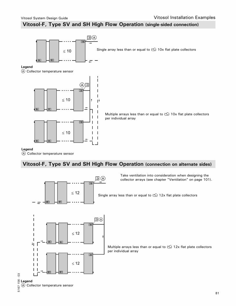
Vitosol System Design Guide
81
5167 1
56 -
03
A Collector temperature sensorLegend
A Collector temperature sensorLegend
A Collector temperature sensorLegend
Vitosol-F, Type SV and SH High Flow Operation (single-sided connection)
Vitosol-F, Type SV and SH High Flow Operation (connection on alternate sides)
Take ventilation into consideration when designing the collector arrays (see chapter "Ventilation" on page 101).
Vitosol Installation Examples
Multiple arrays less than or equal to () 10x flat plate collectorsper individual array
Multiple arrays less than or equal to () 12x flat plate collectorsper individual array
Single array less than or equal to () 10x flat plate collectors
Single array less than or equal to () 12x flat plate collectors

Vitosol System Design Guide
5167 1
56 -
03
82
A Collector temperature sensor
A Collector temperature sensor
Legend
Legend
Vitosol-F, Type SV and SH Low Flow Operation (single-sided connection)
Vitosol-F, Type SV and SH Low Flow Operation (connection on alternate sides)
Single array less than or equal to () 8x flat plate collectors
Single array less than or equal to () 10x flat plate collectors
Vitosol Installation Examples

Vitosol System Design Guide
83
5167 1
56 -
03
Vitosol Installation Examples
Take ventilation into consideration when designing the collector arrays (see chapter "Ventilation" on page 101).Single row installation; connection from the left or right
Vitosol 200-T, Type SPE Vertical Installation (sloped roof and on supports)
Installation in several rows, connection from the left or right
1 collector array With this type of connection, the "Evacuated tube collector" function on the SCU 124/224/345 must be enabled.
2 or more collector arrays ≥43.1 ft2 (≥ 4 m2) With this type of connection, the "Evacuated tube collector" function on the SCU 124/224/345 must be enabled.
LegendA Collector temperature sensor
Vitosol 200-T, Type SPE Horizontal Installation (sloped roof and on supports)
LegendA Collector temperature sensor
LegendA Collector temperature sensor
Multiple arrays greater than or equal to ≥43.1 ft2 (≥4 m2) collector obsorber area
Maximum 215 ft2 (20 m2) absorber area can be connected in series to form a single array.
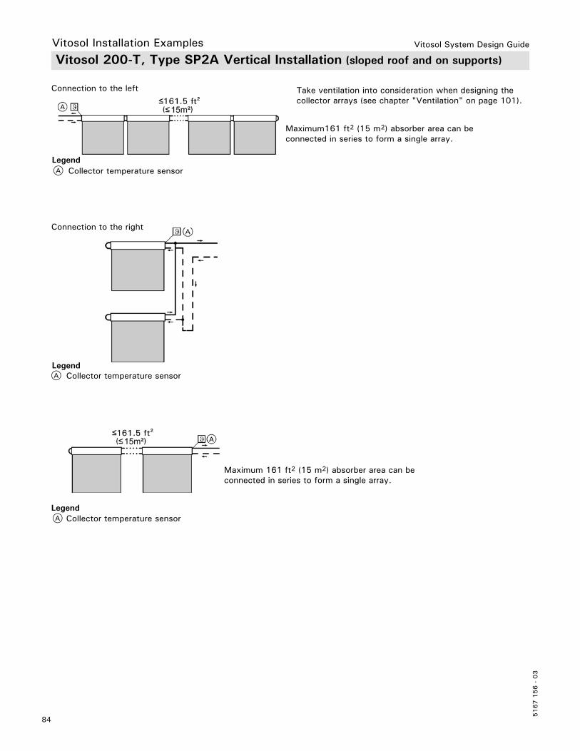
Vitosol System Design Guide
5167 1
56 -
03
84
Take ventilation into consideration when designing the collector arrays (see chapter "Ventilation" on page 101).
Maximum161 ft2 (15 m2) absorber area can be connected in series to form a single array.
A Collector temperature sensor
A Collector temperature sensor
A Collector temperature sensorLegend
Legend
Legend
Connection to the left
Connection to the right
Vitosol 200-T, Type SP2A Vertical Installation (sloped roof and on supports)
Maximum 161 ft2 (15 m2) absorber area can be connected in series to form a single array.
Vitosol Installation Examples

Vitosol System Design Guide
85
5167 1
56 -
03
Vitosol Installation Examples
With this connection, the "Evacuated tube collector" function on the SCU 124/224/345 must be enabled (see chapter "Functions" in the “Solar Control” section).
1 collector arraySingle sided connection from below (preferred version)
2 or more collector arrays ≥43.1 ft2 (≥ 4 m2) With this connection, the "Evacuated tube collector" function on the SCU 124/224/345 must be enabled (see chapter "Functions" in the "Solar Control" section).
A Collector temperature sensorLegend
Vitosol 200-T, Type SP2A Horizontal Installation (sloped roof and on supports)
Vitosol System Design Guide
5167 1
56 -
03
86
Sizing the Solar Thermal SystemDesign and Operation
The sizing of a solar thermal system must take the size of the DHW load into careful consideration, to avoid system overheating due to excess solar energy. Ideally the solar system should be sized to capture and store the amount of energy required for the daily consumption of DHW. Over estimated DHW loads, oversized collector arrays and undersized solar storage tanks are common design errors that result in problems with overheating in the collector loop. The resulting collector stagnation will cause glycol degradation, increased system maintenance, and possible system failure.
To avoid over sizing, it is important to try not to cover too much of the DHW load with solar. It is recommended that for small scale solar DHW systems a maximum solar coverage of 55-60% be targeted. For larger commercial scale systems a maximum solar cover rate of 40-45% is often advisable.
Commercially available solar simulation software programs such as T*Sol, ESOP, RetScreen or Polysun should be used to evaluate any solar system design. These programs allow for the many system parameters to be manipulated and adjusted to come up with the optimal design. Viessmann provides solar design services and will be happy to provide solar simulations for your project.
Calculating the DHW consumptionThe most important first step in system sizing is to establish the size of the average daily DHW load. This load information is not always readily available, but it can be either measured or estimated. For calculating the demand and consumption of DHW, we have to differentiate between the maximum demand of a point of use, and the design consumption.
H The maximum demand of a point of use is often based on the number of fixtures, and forms the calculation base to safeguard the supply of sufficient DHW at all times. It is the engineering variable for sizing the auxiliary DHW tank, and reheat output of the boiler. The maximum demand of the point of use should not be used for sizing the solar system.
H The design consumption forms the basis for the ideal utilisation of the solar thermal system. The design consumption describes the average expected daily consumption, and it is the engineering variable for sizing the solar thermal system. If the load is lower in the summer months then use this rate for solar system sizing.
The maximum demand at the point of use is often higher by a factor of 2 than the actual daily consumption. Where possible, the consumption should be measured with a water meter in the cold water line to the DHW tanks over a longer period of time to aid the system engineering. However, for practical reasons this is not always possible. If no accurate details can be measured for the point of use, the consumption can be estimated based on industry recognized consumption data.
Typical examples of consumption rates are as follows:
H In a detached house the average consumption per head is higher than in apartment buildings. The consumption is assumed to be 8 to 12 USG (30 L to 45 L) per person at 140°F (60°C).
H For apartment buildings, the recommended value (according to VDI 6002 part 1) is 6 USG (22 L) per person at 140°F (60°C).
If unsure of the exact design consumption it is better to underestimate the consumption to avoid solar system over sizing.

Vitosol System Design Guide
87
5167 1
56 -
03
Heat rejection units In cases where the DHW load is very intermittent or much lower in the summer months, some type of mechanical heat rejection unit in the solar loop must be used to minimize collector stagnation and glycol degradation. The heat rejection unit can take the form of a fan coil unit, finned tube radiators, or a ground loop. The rejection unit should be sized based on the maximum possible output of the solar collector array, and all parts of the rejection loop must be rated for temperatures of at least 200°F (95°C). For Vitosol collectors it is recommended to size the rejection unit at 225 Btu/h per ft2 of collector aperture area. The control of the heat rejection circuit should be based on the collector temperature sensor, and activated by the SCU solar controller.
Type of solar application:
DHW heating with low usage rate and high Solar Fraction (residential)
DHW heating with high usage rate and low Solar Fraction (commercial)
Combi systems, DHW + space heating supplement
Storage requirements: USG / ft2 collector aperture area
1.23 – 1.6 0.85 – 1.23 1.72 – 2.45
Storage requirements: L / m2 collector aperture area
50 – 65 35 – 50 70 – 100
Solar storage tank requirementsFossil fuel fired DHW heaters can turn on and heat water when there is a demand, and off when there is not. Solar water heaters however must collect energy when the insolation is available, and store the energy for when there is a demand. The period of heat generation and the period of consumption are rarely the same, so having sufficient solar storage tank capacity is essential for the efficient operation of the solar system. Insufficient storage capacity will lead to higher temperatures in the collector loop, resulting in low collector efficiency, reduced system yields and collector stagnation. In almost all cases more storage volume equals better system efficiency. The amount of storage required is based on the type of solar application and the size of the collector array. The following can be used as a guideline for selecting the solar storage tank requirements:
Sizing the Solar Thermal System (continued)
Design and Operation

Vitosol System Design Guide
5167 1
56 -
03
88
Design and Operation System for Heating DHW
DHW heating in detached houses can be realized either with one dual coil solar DHW tank or with one single coil (for retrofitting an existing system) solar tank preheating the water prior to the auxiliary DHW tank.
Examples: For further detailed examples, see the "Sample Piping Layout Drawings” manual, available for download from the from the Viessmann website.
Single coilThe basis for sizing a solar thermal system for DHW heating is the DHW demand. Viessmann solar packages are sized for a solar coverage up to 60%. The tank capacity must be greater than the daily DHW demand, taking the required DHW temperature into account.To achieve solar coverage of approx. 60%, the collector system must be sized so that the entire tank capacity can be heated on a single sunny day (5 hours of full sunshine) to at least 140°F (60°C) . This would enable poor insolation the following day to be bridged.
System with a dual coil DHW tank
System with single coil and a direct fired DHW tank
The details in the table apply under the following conditions: – SW, S or SE orientation– Roof pitches from 25° to 55°
System with two single coil DHW tanks
General sizing guidelines for DHW heating systemsOccupants Daily DHW demand
in USG (L) [at 120°F (50° C)]
Tank capacity in USG (L)
Collector
Dual coil Single coil No. ofVitosol-F SV/SH
Surface areaVitosol-T
1-2 20-30 (75-113) 66 (250) 53 (200) 1 x SV/SH 1 x 1.51
3-4 45-60 (170-227) 79 (300) 79 (300) 2 x SV/SH 1 x 3.03
5-6 75-90 (288-340) 120 (450) 79 (300) 3 x SV/SH 1 x 3.03 + 1 x 1.51
7-9 105-135 (400-510) N/R 120 (450) 4 x SV/SH 2 x 3.03
10-15 150-225 (75-113) N/R 120 (450) 5 x SV/SH 2 x 3.03 + 1 x 1.51
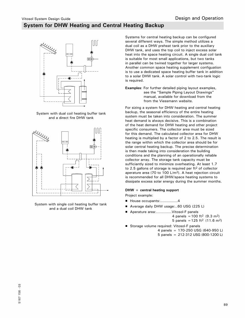
Vitosol System Design Guide
89
5167 1
56 -
03
Design and Operation
Systems for central heating backup can be configured several different ways. The simple method utilizes adual coil as a DHW preheat tank prior to the auxiliary DHW tank, and uses the top coil to inject excess solar heat into the space heating circuit. A single dual coil tank is suitable for most small applications, but two tanks in parallel can be twined together for larger systems. Another common space heating supplement configuation is to use a dedicated space heating buffer tank in addition to a solar DHW tank. A solar control with two-tank logic is required.
For sizing a system for DHW heating and central heating backup, the seasonal efficiency of the entire heating system must be taken into consideration. The summer heat demand is always decisive. This is a combination of the heat demand for DHW heating and other project specific consumers. The collector area must be sized for this demand. The calculated collector area for DHW heating is multiplied by a factor of 2 to 2.5. The result is the range within which the collector area should be for solar central heating backup. The precise determination is then made taking into consideration the building conditions and the planning of an operationally reliable collector array. The storage tank capacity must be sufficiantly sized to minimize overheating. At least 1.7 to 2.5 gallons of storage is required per ft2 of collector aperature area (70 to 100 L/m2). A heat rejection circuit is recommended for all DHW/space heating systems to dissipate excess solar energy during the summer months.
DHW + central heating supportProject example:
H House occupants:...............4
H Average daily DHW usage:..60 USG (225 L)
H Aperature area:.............Vitosol-F panels 4 panels =100 ft2 (9.3 m2) 5 panels =125 ft2 (11.6 m2)
H Storage volume required: Vitosol-F panels 4 panels = 170-250 USG (640-950 L)
5 panels = 212-312 USG (800-1200 L)
System with single coil heating buffer tank and a dual coil DHW tank
System with dual coil heating buffer tank and a direct fire DHW tank
System for DHW Heating and Central Heating Backup
Examples: For further detailed piping layout examples, see the "Sample Piping Layout Drawings” manual, available for download from the from the Viessmann website.

Vitosol System Design Guide
5167 1
56 -
03
90
A Central heating demand for a house (conventional housing stock)B Central heating demand for a low energy houseC DHW demandD Solar yield at 53.8 ft2 (5 m2) absorber areaE Solar yield at 161.5 ft2 (15 m2) absorber area
General sizing guidelines for DHW heating and central heating systems
Occupants Daily DHW demandin USG (L)
[at 120°F (50° C)]
Buffer tank capacity in USG (L)
Collector
No. of Vitosol-F Area of Vitosol-T, type SP2A2 30 (115)
3 45 (170) 200 (750) 4 x SV4 x SH
2x 32.61 ft2 (2x 3.03 m2)
4 60 (230)
5 75 (280) 250 (950) 5 x SV5 x SH
2x 32.61 ft2 (2x 3.03 m2)
6 90 (340)1x 16.25 ft2 (1x 1.51 m2)
7 105 (400) 300 (1150) 6 x SV6 x SH
3x 32.61 ft2 (3x 3.03 m2)
8 120 (450)
For low energy houses [space and DHW heat demand less than 1,836 MBH/ft2 (50 kWh/m2) per annum], solar coverage of up to 35%, relative to the total energy demand, incl. DHW heating, can be achieved according to this sizing. For buildings with a higher heat demand, the coverage is much lower. The Viessmann calculating program “ESOP”, or other available solar simulation software programs, can be used for the exact calculation. Contact your Viessmann sales representative for a customized design and sizing analysis for your project.
Legend
System for DHW Heating and Central Heating Backup (continued)
Design and Operation

Vitosol System Design Guide
91
5167 1
56 -
03
Design and Operation Swimming Pool Heating System – Heat Exchanger and Collector
Typical temperature curve of an outdoor pool (average monthly values)
Project example:Location: BostonPool surface area: 430 ft.2 (40 m2)Depth: 5 ft. (1.5 m)Position: sheltered and covered at night
The diagram shows what average temperature increase can be achieved with which ratio of absorber area to pool surface. This ratio is independent of the collector type used due to the comparably low collector temperatures and the operating period (summer).
Note: Heating and maintaining the pool temperature at a higher set temperature using a conventional heating system does not alter this ratio. However, the pool will be heated up much more quickly.
Outdoor poolsIn northern climates, outdoor pools are mainly used between May and September. Your energy consumption depends primarily on the leakage rate, evaporation, loss (water must be replenished cold) and transmission heat loss. By using a cover, the evaporation and consequently the energy demand of the pool can be reduced to a minimum.
The largest energy input comes directly from the sun, which shines onto the pool surface. Therefore the pool has a "natural" base temperature that can be shown in the following diagram as an average pool temperature over the operating time. A solar thermal system does not alter this typical temperature pattern. The solar application leads to a definite increase in the base temperature. Subject to the ratio between the pool surface and the absorber area, a different temperature increase can be reached.

Vitosol System Design Guide
5167 1
56 -
03
92
Design and Operation Swimming Pool Heating System – Heat Exchanger and Collector (continued)
Indoor poolsIndoor pools generally have a higher target temperature than outdoor pools and are used throughout the year. If, over the course of the year, a constant pool temperature is required, indoor pools must be heated in dual mode. To avoid sizing errors, the energy demand of the pool must be measured. For this, suspend reheating for 48 hours and determine the temperature at the beginning and end of the test period. The daily energy demand can therefore be calculated from the temperature differential and the capacity of the pool. For new projects, the heat demand of the swimming pool must be calculated.
Calculation example for Vitosol 200-FPool surface area:....................387 ft2 (36 m2)Average pool depth:.................5 ft. (1.5 m)Pool capacity:.........................14,300 USG (54,126 L)Temperature loss per day:........1.8°F (1°C)Daily energy demand:...............Q=mcp ∆T
On a summer’s day (clear skies), a collector system used to heat a swimming pool in northern climates produces energy of approx. 1427 Btu/ft2 (4.5 kWh/m2) absorber area.
Imperial Units Metric Units
Daily energy demandm= 14,300 USG x 8.33 lbs/USG=119,119 lbs (of water)cp= 1Btu/lb°F (water)∆T= 1.8°F/day
Q= mcp ∆TQ= 119,119 lbs x 1 Btu/lb°F x 1.8°FQ= 214,414 Btu
Daily energy demandm= 54,126 L x 1.0 kg/L= 54,126 kg (of water)cp= 1.163 Wh/kg°C (water)∆T= 1°C/day
Q= mcp ∆TQ= 54,126 kg x 1.163 Wh/kg°C x 1°CQ= 62,948 Wh (62.94 kWh)
Collector area required214,414 Btu 1427 Btu/ft2= 150 ft2
Since Vitosol-F= 25 ft2 (absorber area)150 ft2 25= 6x collectors
Collector area required62.94 kWh 4.5 kWh/m2= 13.99 m2
Since Vitosol-F= 2.32 m2 (absorber area)13.99 m2 2.32= 6x collectors

Vitosol System Design Guide
93
5167 1
56 -
03
Collector systems can be operated with different specific flow rates. The unit for this is the flow rate in L/h/m2 or USG/min/ft2. The reference variable is the absorber area. All Vitosol collectors have a minimum required flow rates (low flow) and maximum flow rates (high flow). The collectors must operate within this range and the system designer must choose a flow rate based on the specific parameters of the system. At the same collector output, a higher flow rate means a lower ∆T or temperature spread across the collector array. Inversely a lower flow rate will have a higher ∆T or temperature spread across the collector array. When the ∆T or temperature spread across the collector array becomes too large, the efficiency of the collectors will also decrease.
For larger solar installations, high flow is usually not recommended as this results in bigger pumps and larger pipe sizes. Typically low flow would be used as the decreased flow requirements result in smaller pumps which would use less energy, and small pipe sizes, reducing the overall installation and operating cost for the system.
Which operating mode is the right one?Since every project has it’s own unique combination of collector array size and piping length, the designer can choose the flow rate that best meets the requirements of the project. The specific flow rate must be high enough to ensure a reliable and even flow through the entire array. High flow mode is usually best for smaller collector arrays and low flow mode is often used for larger scale projects.
The optimum flow rate (relative to the current tank temperatures and the current insolation level) insystems with a Viessmann solar control unit will adjust itself automatically in matched flow operation. Single array systems with Vitosol-F or Vitosol-T can be operated without problems down to approx. 50% of the specific flow rate.
Example: 50 ft2 (4.6 m2) absorber areaTarget flow rate: 0.02 USG/min/ft2 (45 L/h/m2)This results in the following: 0.91 USG/min (207 L/h) , i.e. approx. 0.9 USG/min (3.45 L/min)
This value should be reached at 100% pump rate. An adjustment can be made at the speed control switch of the pump. The positive primary energetic effect is lost if the required collector flow rate is achieved through a higher pressure drop (= higher power consumption). Choose the pump stage that lies above the required value. The flow rate is automatically reduced via the control unit through a lower current supply to the solar circuit pump.
Operating modes:Low flow operationOperation with flow rates up to approx. 0.014 USG/min/ft2
0.010 - 0.0143 USG/min/ft2 (25 - 35 L/h/m2)
High flow operationOperation with flow rates greater than 0.014 USG/min/ft2
0.0143 - 0.0245 USG/min/ft2 (35 - 60 L/h/m2)
Matched flow operationOperation with variable flow rates based on actual temperature spread across panels. This mode is possible with all SCU solar controls.
All operating modes are possible with Viessmann collectors.
Flow Rate in the Collector ArrayDesign and Operation

Vitosol System Design Guide
5167 1
56 -
03
94
Flow Rate - Vitosol 100-F / 200-F
High-flow modeHigh-flow mode is best suited for small scale systems consisting of less than 8 collectors.
Medium and low-flow modesMedium and low-flow modes are best suited for larger scale collector arrays consisting of greater than 8 collectors.
Flow High flow modeUSG/min (L/min)
Medium flow modeUSG/min (L/min)
Low flow modeUSG/min (L/min)
SV and SH models 0.61 (2.32) 0.45 (1.74) 0.31 (1.16)
Vitosol 100-F / 200-F recommended flow rates
Collector array flow rates
Flow High flow modeUSG/min (L/min)
Medium flow modeUSG/min (L/min)
Low flow modeUSG/min (L/min)
2 collectors 1.22 (4.6) -- --
3 collectors 1.83 (6.9) -- --
4 collectors 2.44 (9.2) -- --
5 collectors 3.05 (11.5) -- --
6 collectors 3.66 (13.8) -- --
8 collectors -- 3.6 (13.6) 2.48 (9.4)
10 collectors -- 4.5 (17.0) 3.1 (11.7)
12 collectors -- 5.4 (20.4) 3.72 (14.1)
Design and Operation
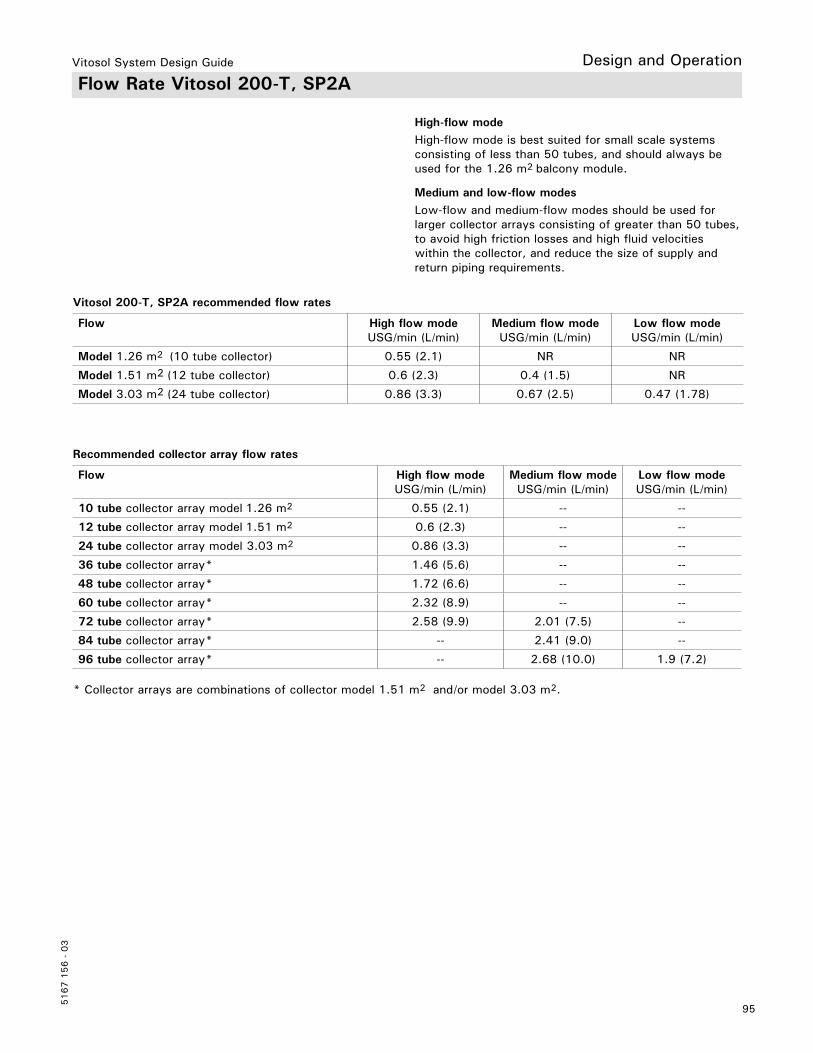
Vitosol System Design Guide
95
5167 1
56 -
03
Design and Operation Flow Rate Vitosol 200-T, SP2A
High-flow modeHigh-flow mode is best suited for small scale systems consisting of less than 50 tubes, and should always be used for the 1.26 m2 balcony module.
Medium and low-flow modesLow-flow and medium-flow modes should be used for larger collector arrays consisting of greater than 50 tubes, to avoid high friction losses and high fluid velocities within the collector, and reduce the size of supply and return piping requirements.
Flow High flow modeUSG/min (L/min)
Medium flow modeUSG/min (L/min)
Low flow modeUSG/min (L/min)
Model 1.26 m2 (10 tube collector) 0.55 (2.1) NR NR
Model 1.51 m2 (12 tube collector) 0.6 (2.3) 0.4 (1.5) NR
Model 3.03 m2 (24 tube collector) 0.86 (3.3) 0.67 (2.5) 0.47 (1.78)
Vitosol 200-T, SP2A recommended flow rates
Recommended collector array flow rates
Flow High flow modeUSG/min (L/min)
Medium flow modeUSG/min (L/min)
Low flow modeUSG/min (L/min)
10 tube collector array model 1.26 m2 0.55 (2.1) -- --
12 tube collector array model 1.51 m2 0.6 (2.3) -- --
24 tube collector array model 3.03 m2 0.86 (3.3) -- --
36 tube collector array* 1.46 (5.6) -- --
48 tube collector array* 1.72 (6.6) -- --
60 tube collector array* 2.32 (8.9) -- --
72 tube collector array* 2.58 (9.9) 2.01 (7.5) --
84 tube collector array* -- 2.41 (9.0) --
96 tube collector array* -- 2.68 (10.0) 1.9 (7.2)
* Collector arrays are combinations of collector model 1.51 m2 and/or model 3.03 m2.
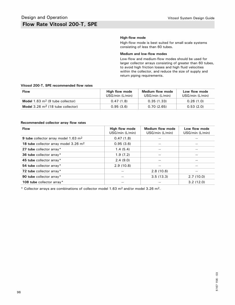
Vitosol System Design Guide
5167 1
56 -
03
96
Flow Rate Vitosol 200-T, SPE
High-flow modeHigh-flow mode is best suited for small scale systems consisting of less than 60 tubes.
Medium and low-flow modesLow-flow and medium-flow modes should be used for larger collector arrays consisting of greater than 60 tubes, to avoid high friction losses and high fluid velocities within the collector, and reduce the size of supply and return piping requirements.
Flow High flow modeUSG/min (L/min)
Medium flow modeUSG/min (L/min)
Low flow modeUSG/min (L/min)
Model 1.63 m2 (9 tube collector) 0.47 (1.8) 0.35 (1.33) 0.26 (1.0)
Model 3.26 m2 (18 tube collector) 0.95 (3.6) 0.70 (2.65) 0.53 (2.0)
Vitosol 200-T, SPE recommended flow rates
Recommended collector array flow rates
Flow High flow modeUSG/min (L/min)
Medium flow modeUSG/min (L/min)
Low flow modeUSG/min (L/min)
9 tube collector array model 1.63 m2 0.47 (1.8) -- --
18 tube collector array model 3.26 m2 0.95 (3.6) -- --
27 tube collector array* 1.4 (5.4) -- --
36 tube collector array* 1.9 (7.2) -- --
45 tube collector array* 2.4 (9.0) -- --
54 tube collector array* 2.9 (10.8) -- --
72 tube collector array* -- 2.8 (10.6) --
90 tube collector array* -- 3.5 (13.3) 2.7 (10.0)
108 tube collector array* -- -- 3.2 (12.0)
* Collector arrays are combinations of collector model 1.63 m2 and/or model 3.26 m2.
Design and Operation
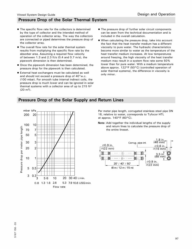
Vitosol System Design Guide
97
5167 1
56 -
03
Design and Operation Pressure Drop of the Solar Thermal System
H The specific flow rate for the collectors is determined by the type of collector and the intended method of operation of the collector array. The way the collectors are connected or piped determines the pressure drop of the collector array.
H The overall flow rate for the solar thermal system results from multiplying the specific flow rate by the absorber area. Assuming a required flow velocity of between 1.3 and 2.3 ft/s (0.4 and 0.7 m/s), the pipework dimension is then determined.
H Once the pipework dimension has been determined, the pressure drop for the pipework is then calculated.
H External heat exchangers must be calculated as well and should not exceed a pressure drop of 40”w.c. (100 mbar). For smooth tube internal indirect coils, the pressure drop is much lower and can be ignored in solar thermal systems with a collector area of up to 215 ft2
(20 m2).
H The pressure drop of further solar circuit components can be seen from the technical documentation and is included in the overall calculation.
H When calculating the pressure drop, take into account the fact that the heat transfer medium has a different viscosity to pure water. The hydraulic characteristics become more similar to water as the temperature of the heat transfer medium increases. At low temperatures around freezing, the high viscosity of the heat transfer medium may result in a system flow rate some 50% lower than for pure water. With a medium temperature above approx. 122°F (50°C) (controlled operation of solar thermal systems), the difference in viscosity is only minor.
Pressure Drop of the Solar Supply and Return Lines
Per meter pipe length, corrugated stainless steel pipe DN 16, relative to water, corresponds to Tyfocor HTL at approx. 140°F (60°C).
Note: Add together the individual lengths of the supply and return lines to calculate the pressure drop of the entire lineset.
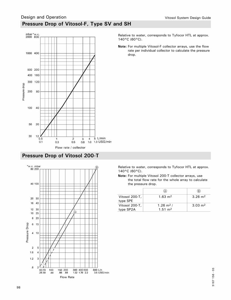
Vitosol System Design Guide
5167 1
56 -
03
98
A B
Vitosol 200-T, type SPE
1.63 m2 3.26 m2
Vitosol 200-T, type SP2A
1.26 m2 /1.51 m2
3.03 m2
Flow Rate
Pres
sure
Dro
p
Relative to water, corresponds to Tyfocor HTL at approx. 140°C (60°C).Note: For multiple Vitosol 200-T collector arrays, use the total flow rate for the whole array to calculate the pressure drop.
Pressure Drop of Vitosol-F, Type SV and SH
Relative to water, corresponds to Tyfocor HTL at approx. 140°C (60°C).
Pressure Drop of Vitosol 200-T
Note: For multiple Vitosol-F collector arrays, use the flow rate per individual collector to calculate the pressure drop.
Design and Operation

Vitosol System Design Guide
99
5167 1
56 -
03
Design and Operation
If the flow rate and pressure drop of the entire solar thermal system are known, the pump can be selected on the basis of the pump curve.
Note: The Solar-Divicon and the solar pump assembly are not suitable for direct contact with swimming pool water.
To minimise the pressure drop through the solar thermal system pipework, the flow velocity in the copper pipe should not exceed 3.3 ft/s (1 m/s). In accordance with VDI 6002-1, we recommend flow velocities of between 1.3 and 2.3 ft/s (0.4 and 0.7 m/s). At these flow velocities, a pressure drop of between 0.12 and 0.3 “w.c. (1 and 2.5 mbar) /m pipe length will result.For the installation of collectors, we recommend sizing the pipes as for a normal heating system accordingto flow rate and velocity (see the table on page 95).Subject to the flow rate and pipe dimension, different flow velocities result.
Note: A higher flow velocity results in a higher pressure drop and potentially could erode the walls of the pipework. If the flow velocity is too low, the system will not capture or move the air trapped in the system.
Any residual air that has collected at the collector must be routed downwards through the solar return line to the air vent in the solar divicon. This will have to be manually vented.
Viessmann supplies the Solar-Divicon to simplify the installation and the selection of pumps and safety equipment. For construction and specification see pages 59-60.
Flow Velocity
Sizing the Circulation Pump

Vitosol System Design Guide
5167 1
56 -
03
100
Specific flow rateAbsorber area USG/min/ft2 0.0102 0.0123 0.0143 0.0164 0.0204 0.0245 0.0327
L/h/m2 25 30 35 40 50 60 80Low flow operation High flow operation
m2 ft2 Flow rate in USG/min (L/min)
Flow rate in USG/min (L/min)
2 22 0.22 (0.83)
0.26(1.00)
0.31(1.17)
0.35(1.33)
0.44(1.67)
0.52(2.00)
0.7(2.67)
3 32 0.33(1.25)
0.39(1.50)
0.46(1.75)
0.53(2.00)
0.66(2.50)
0.78(3.00)
1.06(4.00)
4 43 0.44(1.67)
0.53(2.00)
0.61(2.33)
0.71(2.67)
0.88(3.33)
1.06(4.00)
1.42(5.33)
5 54 0.55(2.08)
0.66(2.50)
0.77(2.92)
0.88(3.33)
1.1(4.17)
1.32(5.00)
1.76(6.67)
6 65 0.66(2.50)
0.79(3.00)
0.92(3.50)
1.06(4.00)
1.32(5.00)
1.58(6.00)
2.12(8.00)
7 75 0.77(2.92)
0.92(3.50)
1.08(4.08)
1.23(4.67)
1.54(5.83)
1.84(7.00)
2.46(9.33)
8 86 0.88(3.33)
1.06(4.00)
1.23(4.67)
1.41(5.33)
1.76(6.67)
2.12(8.00)
2.82(10.67)
9 97 0.99(3.75)
1.19(4.50)
1.38(5.25)
1.58(6.00)
1.98(7.50)
2.38 (9.00)
3.16(12.00)
10 108 1.10(4.17)
1.32(5.00)
1.54(5.83)
1.76(6.67)
2.2(8.33)
2.64(10.00)
3.52(13.33)
12 129 1.32(5.00)
1.74(6.60)
1.85(7.00)
2.11(8.00)
2.64(10.00)
3.2(12.00)
4.23(16.00)
14 151 1.54(5.83)
1.84(7.00)
2.16(8.17)
2.46(9.33)
3.08(11.67)
3.7(14.00)
4.9(18.67)
16 172 1.76(6.67)
2.11(8.00)
2.46(9.33)
2.8(10.67)
3.52(13.33)
4.2(16.00)
5.6(21.33)
18 194 1.98(7.50)
2.37(9.00)
2.77(10.50)
3.17(12.00)
3.96(15.00)
4.7(18.00)
6.3(24.00)
20 215 2.20(8.33)
2.6(10.00)
3.1(11.67)
3.5(13.33)
4.4(16.67)
5.3(20.00)
7.0(26.67)
25 269 2.75(10.42)
3.3(12.50)
3.8(14.58)
4.4(16.67)
5.5(20.83)
6.6(25.00)
8.8(33.33)
30 323 3.30(12.50)
3.9(15.00)
4.6(17.50)
5.3(20.00)
6.6(25.00)
7.9(30.00)
—
35 377 3.85(14.58)
4.6(17.50)
5.4(20.42)
6.2(23.33)
7.7(29.17)
9.2(35.00)
—
40 430 4.4(16.67)
5.3(20.00)
6.1(23.33)
7.0(26.67)
8.8(33.33)
— —
50 528 5.5(20.85)
6.6(25.00)
7.7(29.17)
8.8(33.33)
— — —
60 646 6.6(25.00)
7.9(30.00)
9.2(35.00)
— — — —
70 753 7.7(29.17)
9.2(35.00)
— — — — —
80 861 8.8(33.33)
— — — — — —
Sizing the Circulation Pump (continued)
use Solar-Divicon DN20
use Solar-Divicon DN25B
Note: The table above is only to be used as a reference. It is important to consider the pressure drop and flow requirements of all components installed on the system when sizing or selecting the circulation pump.
Design and Operation
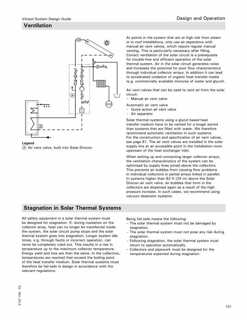
Vitosol System Design Guide
101
5167 1
56 -
03
Design and Operation Ventilation
At points in the system that are at high risk from steam or in roof installations, only use air separators with manual air vent valves, which require regular manual venting. This is particularly necessary after filling.Correct ventilation of the solar circuit is a prerequisite for trouble-free and efficient operation of the solar thermal system. Air in the solar circuit generates noise and increases the potential for poor flow characteristics through individual collector arrays. In addition it can lead to accelerated oxidation of organic heat transfer media (e.g. commercially available mixtures of water and glycol).
Air vent valves that can be used to vent air from the solar circuit:– Manual air vent valve
Automatic air vent valve– Quick-action air vent valve– Air separator
Solar thermal systems using a glycol based heat transfer medium have to be vented for a longer period than systems that are filled with water. We therefore recommend automatic ventilation in such systems. For the construction and specification of air vent valves, see page 61. The air vent valves are installed in the solar supply line at an accessible point in the installation room upstream of the heat exchanger inlet.
When setting up and connecting larger collector arrays, the ventilation characteristics of the system can be optimised by supply lines joined above the collectors. This prevents air bubbles from causing flow problems in individual collectors in partial arrays linked in parallel.In systems higher than 82 ft (25 m) above the Solar Divicon air vent valve, air bubbles that form in the collectors are dispersed again as a result of the high pressure increase. In such cases, we recommend using vacuum deaerator systems.
A Air vent valve, built into Solar-Divicon
All safety equipment in a solar thermal system must be designed for stagnation. If, during insolation on the collector array, heat can no longer be transferred inside the system, the solar circuit pump stops and the solar thermal system goes into stagnation. Longer system idletimes, e.g. through faults or incorrect operation, can never be completely ruled out. This results in a rise in temperature up to the maximum collector temperature. Energy yield and loss are then the same. In the collectors, temperatures are reached that exceed the boiling point of the heat transfer medium. Solar thermal systems must therefore be fail-safe in design in accordance with the relevant regulations.
Being fail-safe means the following:– The solar thermal system must not be damaged by stagnation.– The solar thermal system must not pose any risk during stagnation.– Following stagnation, the solar thermal system must return to operation automatically.– Collectors and pipework must be designed for the temperatures expected during stagnation.
Legend
Stagnation in Solar Thermal Systems
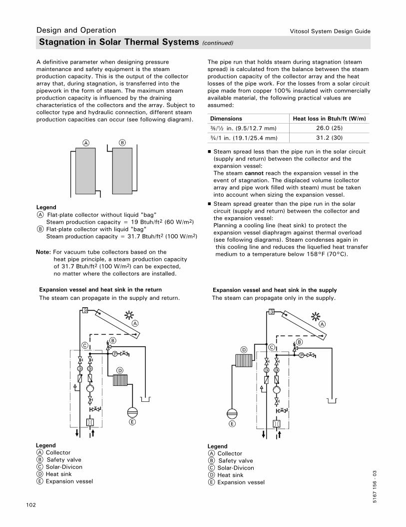
Vitosol System Design Guide
5167 1
56 -
03
102
A definitive parameter when designing pressure maintenance and safety equipment is the steam production capacity. This is the output of the collector array that, during stagnation, is transferred into the pipework in the form of steam. The maximum steam production capacity is influenced by the draining characteristics of the collectors and the array. Subject to collector type and hydraulic connection, different steam production capacities can occur (see following diagram).
A Flat-plate collector without liquid "bag" Steam production capacity = 19 Btuh/ft2 (60 W/m2)B Flat-plate collector with liquid "bag" Steam production capacity = 31.7 Btuh/ft2 (100 W/m2)
Note: For vacuum tube collectors based on the heat pipe principle, a steam production capacity of 31.7 Btuh/ft2 (100 W/m2) can be expected, no matter where the collectors are installed.
Dimensions Heat loss in Btuh/ft (W/m)
e/b in. (9.5/12.7 mm) 26.0 (25)
c/1 in. (19.1/25.4 mm) 31.2 (30)
The pipe run that holds steam during stagnation (steam spread) is calculated from the balance between the steam production capacity of the collector array and the heat losses of the pipe work. For the losses from a solar circuit pipe made from copper 100% insulated with commercially available material, the following practical values are assumed:
H Steam spread less than the pipe run in the solar circuit (supply and return) between the collector and the expansion vessel:
The steam cannot reach the expansion vessel in the event of stagnation. The displaced volume (collector array and pipe work filled with steam) must be taken into account when sizing the expansion vessel.
H Steam spread greater than the pipe run in the solar circuit (supply and return) between the collector and the expansion vessel:
Planning a cooling line (heat sink) to protect the expansion vessel diaphragm against thermal overload (see following diagrams). Steam condenses again in this cooling line and reduces the liquefied heat transfer medium to a temperature below 158°F (70°C).
Stagnation in Solar Thermal Systems (continued)
Expansion vessel and heat sink in the return Expansion vessel and heat sink in the supplyThe steam can propagate in the supply and return. The steam can propagate only in the supply.
Legend
Design and Operation
LegendA CollectorB Safety valveC Solar-DiviconD Heat sinkE Expansion vessel
LegendA CollectorB Safety valveC Solar-DiviconD Heat sinkE Expansion vessel

Vitosol System Design Guide
103
5167 1
56 -
03
Design and Operation
The necessary residual cooling capacity is determined from the differential between the steam production capacity of the collector array and the heat dissipation of the pipework up to the connection point for the expansion vessel and the heat sink.
The program offers three options:– Sufficiently long, uninsulated pipework branching to the expansion vessel– A sufficiently large pre-cooling vessel, in relation to the cooling capacity– A correctly sized stagnation cooler
Note: The “SOLSEC” program is available at www. viessmann.com for calculating the residual cooling capacity and sizing the heat sink.
For the heat sink, standard radiators with an output calculated at 207 Ra° (115 K) are assumed. To make things clearer, the heating output is given as 167/149°F (75/65°C) in the program.
Note: As contact protection, Viessmann recommends that all stagnation coolers be equipped with a safety grate or heat shield. This will provide contact protection during periods where there is no flow and excessively high surface temperatures. When using commercially available radiators, contact protection must be provided and the connections must be diffusion-proof. All components must be able to withstand temperatures of up to 356°F (180°C).
Stagnation in Solar Thermal Systems (continued)

Vitosol System Design Guide
5167 1
56 -
03
104
Design and Operation System Fluid Calculator
Solar Components Quantity / Item Liquid Content / Item in Liters
Total Liquid Content in Liters
Expansion Tank Safety Cushion x 3.00 =Vitosol 100-F, SV1B x 1.67 =Vitosol 100-F, SH1B x 2.33 =Vitosol 200-F, SV2C x 1.83 =Vitosol 200-F, SH2C x 2.48 =Vitosol 200-T, SP2A 1.26m² (10x Tubes) x 0.75 =Vitosol 200-T, SP2A 1.51m² (12x Tubes) x 0.87 =Vitosol 200-T, SP2A 3.03m² (24x Tubes) x 1.55 =Vitosol 200-T, SPE 1.63m² (9x Tubes) x 0.47 =Vitosol 200-T, SPE 3.26m² (18x Tubes) x 0.92 =Vitosol 200-F, SVK x 1.27 =Solar Divicon, DN20 x 0.30 =Solar Divicon, DN25 x 0.30 =Solar Divicon, DN20B x 0.30 =Solar Divicon, DN25B x 0.50 =Solar Divicon-HX, DN20 x 0.98 =Solar Divicon-HX, DN25 x 1.20 =Vitocell 100-W, CVBA - 66 USG (250 L) x 6.50 =Vitocell 100-W, CVSA - 69 USG (260 L) x 6.50 =Vitocell 100-V, CVA - 42 USG (160 L) x 5.50 =Vitocell 100-V, CVA - 53 USG (200 L) x 5.50 =Vitocell 100-V, CVA - 79 USG (300 L) x 10.00 =Vitocell 100-V, CVA - 119 USG (450 L) x 12.50 =Vitocell 300-V, EVI - 53 USG (200 L) x 10.00 =Vitocell 300-V, EVI - 79 USG (300 L) x 11.00 =Vitocell 300-V, EVI - 119 USG (450 L) x 15.00 =Vitocell 100-B, CVB - 79 USG (300 L) x 10.00 =Vitocell 100-B, CVB - 119 USG (450 L) x 12.50 =Vitocell 300-B, EVB - 79 USG (300 L) x 11.00 =Vitocell 300-B, EVB - 119 USG (450 L) x 15.00 =Vitocell 300-H, EHA - 92 USG (350 L) x 13.00 =Vitocell 300-H, EHA - 119 USG (450 L) x 16.00 =Solar Piping Total Length in ft. Liquid Content / ft.
in LitersTotal Liquid Content
in Litersb” Copper x 0.05 =
c” Copper x 0.10 =1” Copper x 0.17 =1a” Copper x 0.26 =
1b” Copper x 0.36 =½” Insulated Stainless Steel Piping Kit * x 0.08 =
Total Liquid Content of System in Liters (Solar Components + Solar Piping)
Total Liquid Content of System in USG (Total Liquid Content of System in Liters 3.785 =USG)
Note: Use this table to calculate the required amount of liquid content required for the solar thermal system.1) Input the quantities for each listed item and the length of piping (in ft.) used in the system. Then multiply each item by the liquid content listed for each item and input each item total in the Total Liquid Content column.2) Add all of the individual liquid content totals to determine the total liquid content of the system.* This piping kit comes in 20 ft., 40 ft. and 50 ft. lengths (it combines two pipes for supply and return wraped in foam insulation). Example: A 20 ft. piping kit contains 20 ft. of supply and 20 ft. of return with a total length of 40 ft.

Vitosol System Design Guide
105
5167 1
56 -
03
For layout, function and specification of the expansion vessel, see chapter "Installation accessories".
The expansion vessel can be calculated once the steam spread has been determined and any heat sinks that may be used have been taken into consideration.The required volume is determined by the following factors:– Expansion of the heat transfer medium in its liquid state– Liquid seal– Expected steam volume, taking account of the static head of the system– Pre-charge pressure
Vdev = (Vcol + Vdpipe + Ve + Vfv)·Df
Vdev Nominal volume of the expansion vessel in USG (L)Vcol Liquid content of the collectors in USG (L)Vdpipe Content of the pipework subject to steam loads in L (calculated from the steam spread and the pipework content per m pipe length)
Ve Increase in the volume of the heat transfer medium in its liquid state in USG (L) Ve = Va · β Va System volume (content of the collectors, the heat exchanger and the pipework) β Expansion factor β = 0.13 for Viessmann heat transfer medium from -4 to 248°F (-20 to 120°C)Vfv Liquid seal in the expansion vessel [4% of the system volume, min. 0.8 USG (3 L)]Df Pressure factor (pe + 1): (pe − po) pe Max. system pressure at the safety valve in bar (90% of the safety valve response pressure) po System pre-charge pressure po = 14.5 psi + 0.45 psi/ft static head (1 bar + 0.1 bar/m static head)
To determine the system and steam volume in the pipework, the content per ft (m) of pipe must be taken into consideration.
Copper pipe, Dim.type M
in. (mm)
e(9.5)
b(12.7)
c(19.1)
1(25.4)
1a(31.8)
1b(38.1)
Capacity USG/ft (L/m)
0.0083(0.103)
0.013(0.161)
0.027(0.335)
0.045(0.558)
0.0680.844)
0.095(1.18)
Corrugated stainless steel pipe
Dim. DN 160.629 in. (16 mm) I.D.
Capacity USG/ft (L/m)
0.02(0.25)
For the liquid content of the following components see the relevant"Specification" chapter:– Collectors– Solar-Divicon and solar pump assembly– DHW tank and heating water buffer tank
Selection of the expansion vesselThe details in the following table are standard values. They allow quick estimates at the design and calculation stage. These values must be verified by appropriate calculations. The selection relates to system hydraulics with a liquid "bag" (see page 102) and to the use of a 87 psig (6-bar) safety valve.
Note: Check the size of the expansion vessel on site.
Expansion Vessel
Note: The expansion tank can be sized by using the ‘Vitosol Project Tool Kit’ software. Contact your local Viessmann sales representative for details.
Design and Operation

Vitosol System Design Guide
5167 1
56 -
03
106
Vitosol-F, type SV
Absorber area in ft2 (m2) Static head ft. (m) System capacity in USG (L) Recommended capacity of the expansion vessel in USG (L)
25(2.3) 16.4 (5) 5.9 (22.3) 4.8 (18)32.8 (10) 6.8 (25.7) 6.6 (25)49.2 (15) 7.7 (29.2)
50 (4.6) 16.4 (5) 6.5 (24.7) 6.6 (25)32.8 (10) 7.3 (27.6)49.2 (15) 8.2 (31.0)
75 (6.9) 16.4 (5) 7.5 (28.5) 10.6 (40)32.8 (10) 7.8 (29.6)49.2 (15) 8.7 (32.9)
100 (9.3) 16.4 (5) 8.0 (30.3) 10.6 (40)32.8 (10) 8.9 (33.8)49.2 (15) 9.2 (34.7)
125 (11.6) 16.4 (5) 8.5 (32.2) 10.6 (40)32.8 (10) 9.4 (35.6) 13.2 (50)49.2 (15) 10.3 (39.1)
150 (13.9) 16.4 (5) 9.0 (34.0) 10.6 (40)32.8 (10) 9.9 (37.4) 13.2 (50)49.2 (15) 10.8 (40.9) 21.1 (80)
175(16.2) 16.4 (5) 9.5 (35.8) 13.2 (50)32.8 (10) 10.4 (39.3)49.2 (15) 11.3 (42.7) 21.1 (80)
200 (18.6) 16.4 (5) 10.0 (37.7) 13.2 (50)32.8 (10) 10.9 (41.1) 21.1 (80)49.2 (15) 11.8 (44.6)
Absorber area in ft2 (m2) Static head ft (m) System capacity in USG (L) Recommended capacity of the expansion vessel in USG (L)
25 (2.3) 16.4 (5) 6.0 (22.9) 4.8 (18)32.8 (10) 7.0 (26.4) 6.6 (25)49.2 (15) 7.9 (29.8)
50 (4.6) 16.4 (5) 6.9 (26.0) 10.6 (40)32.8 (10) 7.6 (28.9)49.2 (15) 8.5 (32.3)
75 (6.9) 16.4 (5) 8.1 (30.5) 10.6 (40)32.8 (10) 8.3 (31.5)49.2 (15) 9.2 (34.8) 13.2 (50)
100 (9.3) 16.4 (5) 8.7 (32.9) 10.6 (40)32.8 (10) 9.6 (36.4)49.2 (15) 9.9 (37.3) 13.2 (50)
125 (11.6) 16.4 (5) 9.4 (35.4) 13.2 (50)32.8 (10) 10.3 (38.9)49.2 (15) 11.2 (42.3) 21.1 (80)
150 (13.9) 16.4 (5) 10.0 (37.9) 13.2 (50)32.8 (10) 10.9 (41.3) 21.1 (80)49.2 (15) 11.8 (44.8)
175 (16.2) 16.4 (5) 10.7 (40.4) 13.2 (50)32.8 (10) 11.6 (43.8) 21.1 (80)49.2 (15) 12.5 (47.3)
200 (18.6) 16.4 (5) 11.3 (42.9) 21.1 (80)32.8 (10) 12.2 (46.3)49.2 (15) 13.2 (49.8)
Vitosol-F, type SH
Expansion Vessel (continued)
Design and Operation

Vitosol System Design Guide
107
5167 1
56 -
03
Design and Operation
Absorber area in ft2 (m2) Static head ft (m) System capacity in USG (L) Recommended capacity of the expansion vessel in USG (L)
16.3 (1.51) 16.4 (5) 5.7 (21.7) 4.8 (18)32.8 (10) 6.6 (25.1)49.2 (15) 7.6 (28.6) 4.8 (18)
32.6 (3.03) 16.4 (5) 5.9 (22.3) 4.8 (18)32.8 (10) 6.8 (25.7) 6.6 (25)49.2 (15) 7.7 (29.2)
48.9 (4.54) 16.4 (5) 6.2 (23.3) 6.6 (25)32.8 (10) 6.2 (23.6)49.2 (15) 7.9 (29.8) 10.6 (40)
65.2 (6.06) 16.4 (5) 7.0 (26.6) 6.6 (25)32.8 (10) 7.3 (27.5) 10.6 (40)49.2 (15) 8.2 (31.0)
81.5 (7.57) 16.4 (5) 7.3 (27.8) 10.6 (40)32.8 (10) 8.3 (31.3)49.2 (15) 8.5 (32.2) 13.2 (50)
97.8 (9.09) 16.4 (5) 7.5 (28.4) 10.6 (40)32.8 (10) 8.4 (31.9)49.2 (15) 8.7 (32.8) 13.2 (50)
114.1 (10.60) 16.4 (5) 7.7 (29.0) 10.6 (40)32.8 (10) 8.6 (32.5) 13.2 (50)49.2 (15) 8.9 (33.8) 21.1 (80)
130.5 (12.12) 16.4 (5) 8.0 (30.2) 10.6 (40)32.8 (10) 8.9 (33.7) 13.2 (50)49.2 (15) 9.8 (37.1) 21.1 (80)
163.1 (15.15) 16.4 (5) 8.5 (32.0) 10.6 (40)32.8 (10) 9.4 (35.5) 13.2 (50)49.2 (15) 9.8 (37.2) 21.1 (80)
Vitosol-T
Expansion Vessel (continued)
Safety Valve
The heat transfer medium discharged from the solar thermal system via the safety valve if the max. permissible system pressure 87 psig (6 bar) is exceeded. According to DIN 3320, the response pressure of the safety valve is the max. system pressure +10%.The safety valve must comply with EN 12975 and 12977, be matched to the heating output of the collectors and be able to handle their maximumoutput of 222 Btuh/ft2 (900 W/m2).
Discharge and drain lines must terminate in an open high temperature rated container, capable of collecting the total capacity of the collectors. Use only safety valves sized for max. 87 psig (6 bar) and 248°F (120°C), which bear the marking "S" (solar) as part of the product identification.
Note: The Solar-Divicon is equipped with a safety valve for up to 87 psig (6 bar) and 248°F (120°C). Check local codes to determine suitability.

Vitosol System Design Guide
5167 1
56 -
03
108
The solar control units SCU124/224/345 and SM1 are equipped with an electronic temperature limiter. A mechanical high limit safety cut-out in the tank is recommended when the ratio of tank capacity to absorber area is less than 0.98 USG/ft2 (40 L/ m2) tank capacity is available per m2 absorber area. This reliably prevents temperatures above 222°C (95°C) in the tank.
Example: 3 Vitosol-F flat-plate collectors, 75.3 ft2 (7 m2) absorber area DHW tank with 79 USG (300 L) tank capacity. 79 USG/75.3 ft2 = 1.05 USG/ft2 (300 L/7 m2) = (42.8 L/ m2) e.g. a high limit safety cut-out is not required.
To prevent legionella bacteria, DVGW W 551 specifies that the total water content (heated by an auxiliary source) must be maintained at least at 140°F (60°C) and the DHW preheating stages (heated by solar) must be heated once every day to 140°F (60°C).
H Systems with a tank capacity, incl. DHW preheating stages, in excess of 106 USG (400 L)
H Systems with a pipework capacity in excess of 0.8 USG (3 L) from the DHW tank to the draw-off point
Note: For detached and multi-family houses, this heat-up is recommended, but not compulsory. Check local codes to determine requirements for this function.
High Limit Safety Cut-out
Additional Function for DHW Heating
We recommend heating up in late afternoon. This will help ensure that the lower tank area or the preheating stage is cold again following the expected draw-offs (evenings and the following morning) and can subsequently be heated up again by solar energy.
Connecting the DHW Circulation and Thermostatic Mixing Valve
LegendA DHW circulation pumpB Automatic thermostatic mixing valveC Check valveD DHW circulation bypass line. Line required to prevent heating of entire solar tank.E DHW circulation line. Flow temperature max 140°F (60°C).F Thermostatic mixing valve cold water inlet. Pipe runs as short as possible, as these receive no flow in winter.G Dual coil tank heated by solar and boilerH Single coil tank heated by boilerI Single coil solar pre-heat tank
Single tank - solar preheat with DHW backup Multiple tank - solar preheat in line with DHW tank
Design and Operation
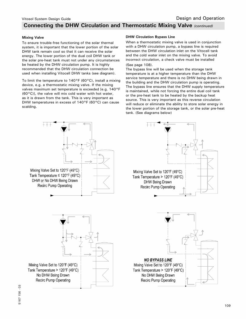
Vitosol System Design Guide
109
5167 1
56 -
03
Design and Operation Connecting the DHW Circulation and Thermostatic Mixing Valve (continued)
Mixing ValveTo ensure trouble-free functioning of the solar thermal system, it is important that the lower portion of the solar DHW tank remain cool so that it can receive the solar energy. The lower portion of the dual coil DHW tank or the solar pre-heat tank must not under any circumstances be heated by the DHW circulation pump. It is highly recommended that the DHW circulation connection be used when installing Vitocell DHW tanks (see diagram).
To limit the temperature to 140°F (60°C), install a mixing device, e.g. a thermostatic mixing valve. If the mixing valves maximum set temperature is exceeded [e.g. 140°F (60°C)], the valve will mix cold water with hot water, as it is drawn from the tank. This is very important as DHW temperatures in excess of 140°F (60°C) can cause scalding.
DHW Circulation Bypass LineWhen a thermostatic mixing valve is used in conjunction with a DHW circulation pump, a bypass line is required between the DHW circulation inlet on the Vitocell tank and the cold water inlet on the mixing valve. To avoid incorrect circulation, a check valve must be installed (See page 108).The bypass line will be used when the storage tank temperature is at a higher temperature than the DHW service temperature and there is no DHW being drawn in the building and the DHW circulation pump is operating. The bypass line ensures that the DHW supply temperature is maintained, while not forcing the entire dual coil tank or the pre-heat tank to be heated by the backup heat source. This is very important as this reverse circulation will reduce or eliminate the ability to store solar energy in the lower portion of the storage tank, or the solar pre-heat tank. (See diagrams below)
Vitosol System Design Guide
5167 1
56 -
03
110
Design and Operation
Vitosol solar systems are only intended to be installed and operated in sealed unvented systems that comply with EN 12828 / DIN 1988, or solar thermal systems that comply with EN 12977, with due attention paid to the associated installation, service and operating instructions. DHWtanks are only designed to store and heat water of potable water quality. Heating water buffer tanks are only designed to hold fill water of potable water quality. Only operate solar collectors with the heat transfer medium approved by the manufacturer.Intended use presupposes that a fixed installation in conjunction with permissible, system-specific components has been carried out. Commercial or industrial usage for a purpose other than heating the building, pool or DHW shall be deemed inappropriate.
Any usage beyond this must be approved by the manufacturer for the individual case. Incorrect usage or operation of the appliance (e.g. the appliance being opened by the system user) is prohibited and results in an exclusion of liability. Incorrect usage also occurs if the components in the system are modified from their intended use (e.g. through direct DHW heating in the collector). Adhere to statutory regulations, especially concerning the hygiene of potable water.
Intended Use
Subsidy Programs, Permits and Insurance
Solar thermal systems play an important role in protecting natural resources and the environment. Together with advanced Viessmann heating systems, they create an optimum system solution that is fit for the future for DHW and swimming pool heating, central heating backupand other low temperature applications. This is why solar thermal systems are frequently subsidised by government.
Solar thermal systems are subsidized by some national, regional and local authorities. Further information is available from our sales offices. All Vitosol collectors are certified to Solar Keymark and SRCC 06-100 standards.
Viessmann collectors meet the requirements of the "Blue Angel" certificate of environmental excellence to RAL UZ 73. The approval of solar thermal systems is not universally regulated. Your local planningoffice will be able to advise you on whether solar thermal systems need planning permission.
Viessmann solar collectors are tested for impact resistance, for example against hailstones, to DIN EN 12975-2. Nevertheless we recommend that the user insures against extreme weather conditions and includes the collectors on their buildings insurance. Damage due to these conditions is excluded from our warranty.

Vitosol System Design Guide
111
5167 1
56 -
03
Glossary
Irradiance (insolation)Radiation level impacting on a unit of surface area, expressed in Btuh/ft2 (W/m2).
AbsorberDevice contained inside a solar collector designed to absorb radiation energy and transfer this as heat to a liquid.
AbsorptionRadiation absorption
ConvectionTransfer of heat by the flow of a medium. Convection creates energy losses caused by a temperature differential, e.g. between the glass pane of the collector and the hot absorber.
CondenserDevice where steam is precipitated as a liquid.
DispersionInteraction of radiation with matter by which the direction of the radiation is altered; total energy and wavelength remain unchanged.
EfficiencyThe operating efficiency of a solar collector is the ratio of the collector output to the power input. Relevant variables are, for example, the ambient and absorber temperatures.
EmissionTransmission (radiation) of beams, e.g. light or particles.
EvacuatingExtraction of the air from a container. This reduces the air pressure, thereby creating a vacuum.
Heat pipeSealed capillary container that contains a small volume of highly volatile liquid.
Heat transfer mediumLiquid that absorbs the available heat in the absorber of the collector and delivers it to a consumer (heat exchanger).
Radiation energyVolume of energy transmitted by radiation.
Selectively coated surfaceThe absorber in the solar collector is highly selective coated to improve its efficiency. This specially applied coating enables the absorption to be maintained at a very high level for the sunlight spectrum that hits the absorber (approx. 94%). The emission of long-wave heat radiation is largely prevented. The highly selective black chromiumcoating is very durable.
Standard roof pitchThe roof pitch limit, at which the roof cover is considered to be adequately protected against the ingress of rain, is described as standard roof pitch. Refer to the roof manufacture’s Installation details regarding roof pitch to ensure adequate weather protection.
Steam production capacityThe output of the collector array in Btuh/ft2 (W/m2) that, during stagnation, is transferred into the pipe work in the form of steam. The max. steam production capacity is influenced by the draining characteristics of the collectors and the collector array (see page 102).
Steam spreadLength of the pipe work that is subjected to steam loads during stagnation. The max. steam spread is dependent on the heat loss characteristics of the pipe work (thermal insulation). Conventional details refer to 100% insulation strength.
VacuumA space devoid of air.
Design and Operation
Tec
hnic
al in
form
atio
n su
bjec
t to
cha
nge
witho
ut n
otic
e.Pr
inte
d on
env
ironm
enta
lly f
riend
ly
(rec
ycle
d an
d re
cycl
able
) pa
per.
Vitosol System Design Guide
5167 1
56 -
03