
VITOSOL 200 - The Initiative Group · VITOSOL 200 Installation instructions for heating engineers...
52
VITOSOL 200 Installation instructions for heating engineers Vitosolɘ200 TypeɘD10, D20 and D30 Direct flow vacuum tube collector 5862ɘ014ɘGBəəə4/2004
Transcript of VITOSOL 200 - The Initiative Group · VITOSOL 200 Installation instructions for heating engineers...

VITOSOL 200
Installation instructionsfor heating engineers
Vitosol�200
Type�D10, D20 and D30
Direct flow vacuum tube collector
5862�014�GB���4/2004

2
Safety instructions
Please follow these safety instructions closely to prevent accidents and
material losses.
Safety regulations
Installation, initial start−up, inspection,
maintenance and repairs must only
be carried out by a competent person
(heating engineer/installation
contractor).
Observe all current safety regulations
as defined by DIN, EN, DVGW and
VDE or locally applicable standards.
See also the safety instructions sheet
in the Vitotec technical documentation
folder.
Before working on the equipment/
heating system/solar heating system,
isolate its mains electrical supply
(e.g. by removing a separate mains
fuse or by means of a mains
electrical isolator) and safeguard
against unauthorised reconnection.
Observe maximum load and distance
from roof edge for the substructure
installed on the roof to DIN�1�055.
Earthing/lightning protection of the
solar heating system
Install an electrical conductor on the
pipework system of the solar circuit
in the lower part of the building to
comply with VDE or local
regulations.
Connection of the collector system to
a new or existing lightning protection
facility or the provision of local
earthing should only be carried out
by authorised personnel, who must
take into account the conditions
applicable on site.
¨�Safety instruction
Denotes information which must be
observed to prevent accidents and
material losses.
58
62
�01
4�G
B

3
Index
Page
Vertical installation on top of roof�
Component summary� 4. . . . . . . . . . . . . . . . . . . . . . . . . . . . . . . . . . . . . . . . . . . . . . . . . . . . . . . . . . . . . . . . . . . . . . . . . . . . . . . . . . . . . . . . . . . . . . . . . . . . . . . . . . .
Installation with roof ties� 6. . . . . . . . . . . . . . . . . . . . . . . . . . . . . . . . . . . . . . . . . . . . . . . . . . . . . . . . . . . . . . . . . . . . . . . . . . . . . . . . . . . . . . . . . . . . . . . . . . . . .
Installation without roof ties (roofs with higher snow loads)� 12. . . . . . . . . . . . . . . . . . . . . . . . . . . . .
Installation without roof ties (e.g. on sheet steel roofs)� 16. . . . . . . . . . . . . . . . . . . . . . . . . . . . . . . . . . . . . . . .
Fitting the mounting rails� 18. . . . . . . . . . . . . . . . . . . . . . . . . . . . . . . . . . . . . . . . . . . . . . . . . . . . . . . . . . . . . . . . . . . . . . . . . . . . . . . . . . . . . . . . . . . . . . . . . . . .
Fitting the connection housing� 19. . . . . . . . . . . . . . . . . . . . . . . . . . . . . . . . . . . . . . . . . . . . . . . . . . . . . . . . . . . . . . . . . . . . . . . . . . . . . . . . . . . . . . . . . .
Horizontal installation on top of roof
Component summary� 20. . . . . . . . . . . . . . . . . . . . . . . . . . . . . . . . . . . . . . . . . . . . . . . . . . . . . . . . . . . . . . . . . . . . . . . . . . . . . . . . . . . . . . . . . . . . . . . . . . . . . . . . . . .
Installation with roof ties� 22. . . . . . . . . . . . . . . . . . . . . . . . . . . . . . . . . . . . . . . . . . . . . . . . . . . . . . . . . . . . . . . . . . . . . . . . . . . . . . . . . . . . . . . . . . . . . . . . . . . . .
Installation without roof ties (roofs with higher snow loads)� 27. . . . . . . . . . . . . . . . . . . . . . . . . . . . .
Installation without roof ties (e.g. on sheet steel roofs)� 30. . . . . . . . . . . . . . . . . . . . . . . . . . . . . . . . . . . . . . . .
Fitting the horizontal mounting rails� 31. . . . . . . . . . . . . . . . . . . . . . . . . . . . . . . . . . . . . . . . . . . . . . . . . . . . . . . . . . . . . . . . . . . . . . . . . . . . . .
Fitting the connection housing� 32. . . . . . . . . . . . . . . . . . . . . . . . . . . . . . . . . . . . . . . . . . . . . . . . . . . . . . . . . . . . . . . . . . . . . . . . . . . . . . . . . . . . . . . . . .
Fitting the vertical mounting rails� 34. . . . . . . . . . . . . . . . . . . . . . . . . . . . . . . . . . . . . . . . . . . . . . . . . . . . . . . . . . . . . . . . . . . . . . . . . . . . . . . . . . . .
Installation on flat roofs�
Component summary� 36. . . . . . . . . . . . . . . . . . . . . . . . . . . . . . . . . . . . . . . . . . . . . . . . . . . . . . . . . . . . . . . . . . . . . . . . . . . . . . . . . . . . . . . . . . . . . . . . . . . . . . . . . . .
Installation� 38. . . . . . . . . . . . . . . . . . . . . . . . . . . . . . . . . . . . . . . . . . . . . . . . . . . . . . . . . . . . . . . . . . . . . . . . . . . . . . . . . . . . . . . . . . . . . . . . . . . . . . . . . . . . . . . . . . . . . . . . . . . . . . . . . .
Installation on walls�
Component summary� 40. . . . . . . . . . . . . . . . . . . . . . . . . . . . . . . . . . . . . . . . . . . . . . . . . . . . . . . . . . . . . . . . . . . . . . . . . . . . . . . . . . . . . . . . . . . . . . . . . . . . . . . . . . .
Installation� 42. . . . . . . . . . . . . . . . . . . . . . . . . . . . . . . . . . . . . . . . . . . . . . . . . . . . . . . . . . . . . . . . . . . . . . . . . . . . . . . . . . . . . . . . . . . . . . . . . . . . . . . . . . . . . . . . . . . . . . . . . . . . . . . . . .
Water connections�
Connecting the connection housing� 44. . . . . . . . . . . . . . . . . . . . . . . . . . . . . . . . . . . . . . . . . . . . . . . . . . . . . . . . . . . . . . . . . . . . . . . . . . . . . . .
Fitting the connection set� 46. . . . . . . . . . . . . . . . . . . . . . . . . . . . . . . . . . . . . . . . . . . . . . . . . . . . . . . . . . . . . . . . . . . . . . . . . . . . . . . . . . . . . . . . . . . . . . . . . . . .
Fitting the vacuum tubes and collector temperature sensor� 48. . . . . . . . . . . . . . . . . . . . . . . . . . . . . . .
Installation� 50. . . . . . . . . . . . . . . . . . . . . . . . . . . . . . . . . . . . . . . . . . . . . . . . . . . . . . . . . . . . . . . . . . . . . . . . . . . . . . . . . . . . . . . . . . . . . . . . . . . . . . . . . . . . . . . . . . . . . . . . . . . . . . . . .
58
62
�01
4�G
B

4
Vertical installation on top of roof
Component summary
58
62
�01
4�G
B
1 2 3 4 6
8 9 qP
qQ qW qE qR qT qZ qI
qO wR
wT wZ wU wI wO
eW eEeP eReQ eT
7
5
wE
5
Vertical installation on top of roofs (cont.)
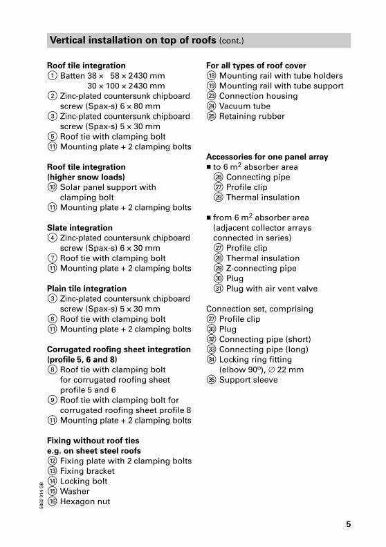
Roof tile integration
1 Batten 38���58��2�430�mm
Batten 30��100��2�430�mm
2 Zinc−plated countersunk chipboard
screw (Spax�s) 6���80�mm
3 Zinc−plated countersunk chipboard
screw (Spax�s) 5���30�mm
5 Roof tie with clamping bolt
qQ Mounting plate + 2�clamping bolts
Roof tile integration
(higher snow loads)
qP Solar panel support with
clamping bolt
qQ Mounting plate + 2�clamping bolts
Slate integration
4 Zinc−plated countersunk chipboard
screw (Spax�s) 6��30�mm
7 Roof tie with clamping bolt
qQ Mounting plate + 2�clamping bolts
Plain tile integration
3 Zinc−plated countersunk chipboard
screw (Spax�s) 5��30�mm
6 Roof tie with clamping bolt
qQ Mounting plate + 2�clamping bolts
Corrugated roofing sheet integration
(profile�5, 6 and 8)
8 Roof tie with clamping bolt
for corrugated roofing sheet
profile�5 and 6
9 Roof tie with clamping bolt for
corrugated roofing sheet profile�8
qQ Mounting plate + 2�clamping bolts
Fixing without roof ties
e.g. on sheet steel roofs
qW Fixing plate with 2�clamping bolts
qE Fixing bracket
qR Locking bolt
qT Washer
qZ Hexagon nut
For all types of roof cover
qI Mounting rail with tube holders
qO Mounting rail with tube support
wE Connection housing
wR Vacuum tube
wT Retaining rubber
Accessories for one panel array
� to 6�m2 absorber area
wZ Connecting pipe
wU Profile clip
wI Thermal insulation
� from 6�m2 absorber area
(adjacent collector arrays
connected in series)
wU Profile clip
wI Thermal insulation
wO Z�connecting pipe
eP Plug
eQ Plug with air vent valve
Connection set, comprising
wU Profile clip
eP Plug
eW Connecting pipe (short)
eE Connecting pipe (long)
eR Locking ring fitting
(elbow 90º), ∅�22�mm
eT Support sleeve
58
62
�01
4�G
B

6
Vertical installation on top of roofs (cont.)
Install the panel array level or slightly inclined (approx. 10�mm) towards the
connection side to ensure complete venting.
Installation with roof ties
Summary
A Mounting rail
B Roof tie
C Additional batten, 38��58�mm
(only for roof tile integration)
D Additional batten, 30��100�mm
(only for roof tile integration)
E Vacuum tube
F Connection housing
G Mounting plate
Dim.�X according to the width of
the tile head at the back.
58
62
�01
4�G
B
GFECBA D CD

7
Vertical installation on top of roofs (cont.)
Combination A
mm
B
mm
C
mm
D
mm
E
mm
D20/D20 800���1�000 1�514 800���1�000 2�953 75
D20/D30 800���1�000 1�864 1�400���1��600 3�663 75
D30/D�30 1�400���1�600 2�223 1�400���1�600 4�372 74
Centre mounting rails when fitting one collector only.
58
62
�01
4�G
B
8
Vertical installation on top of roofs (cont.)
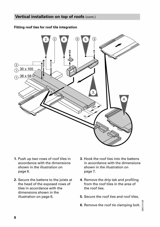
Fitting roof ties for roof tile integration
1. Push up two rows of roof tiles in
accordance with the dimensions
shown in the illustration on
page�6.
2. Secure the battens to the joists at
the head of the exposed rows of
tiles in accordance with the
dimensions shown in the
illustration on page�6.
3. Hook the roof ties into the battens
in accordance with the dimensions
shown in the illustration on
page�7.
4. Remove the drip tab and profiling
from the roof tiles in the area of
the roof ties.
5. Secure the roof ties and roof tiles.
6. Remove the roof tie clamping bolt.
58
62
�01
4�G
B
3.
2. 6 5.
2
2
4.
35
1
1
30 x 100
38 x 58

9
Vertical installation on top of roofs (cont.)
7. Set the mounting plate onto the
roof ties of the top row and align;
insert dowel pin.
8. Fit clamping bolts to the roof ties;
do not tighten the screws yet.
Continue with mounting rail
installation on page�18.
Fitting roof ties for slate integration
1. Mark the position of the roof ties
in accordance with the dimensions
shown in the illustration on
page�7.
2. Remove slates from the roof tie
location.
3. Secure the roof ties to the roof face.
Utilise commercial lead flashing to
prevent the ingress of moisture.
4. Cover the roof.
5. Remove the roof tie clamping bolt.
6. Set the mounting plate onto the
roof ties of the top row and align;
insert dowel pin.
7. Fit clamping bolts to the roof ties;
do not tighten the screws yet.
Continue with mounting rail
installation on page�18.
58
62
�01
4�G
B
5
8.
7.
6.
5.
2.
3.7.
4
7

10
Vertical installation on top of roofs (cont.)
Fitting roof ties in the case of plain roof tile integration
1. Mark the position of the roof ties
in accordance with the dimensions
shown in the illustration on
page�7.
2. Remove tiles from the roof tie
location.
3. Hook the roof ties onto the
battens, locate and align on top of
the tile below.
4. Secure the roof ties to the battens.
5. Remove the roof tie clamping bolt.
6. Set the mounting plate onto the
roof ties of the top row and align;
insert dowel pin.
7. Fit clamping bolts to the roof ties;
do not tighten the screws yet.
8. Cover the roof; match tiles with an
angle cutter. Trim tiles approx.
35�mm.
Continue with mounting rail
installation on page�18.
58
62
�01
4�G
B
5.
62.
3.
3
4.
7.
6.
6
0

11
Vertical installation on top of roofs (cont.)
Fitting roof ties in the case of corrugated roofing sheet integration
1. Mark the position of the roof ties
in accordance with the dimensions
shown in the illustration on
page�7.
2. Position the roof ties at the level of
a batten onto the ridge of the plate
and drill a hole into the ridge of
the plate through the hole in the
roof tie.
3. Secure the roof ties with hexagon
woodscrews ∅�8�mm (on−site
provision) to the battens.
4. Push on the top part of the roof
ties.
5. Set the mounting plate onto the
roof ties of the top row and align;
insert dowel pin.
6. Fit clamping bolts to the roof ties;
do not tighten the screws yet.
Continue with mounting rail
installation on page�18.
58
62
�01
4�G
B
8,9
2.
6.
5.
4.
3.
12
Vertical installation on top of roofs (cont.)
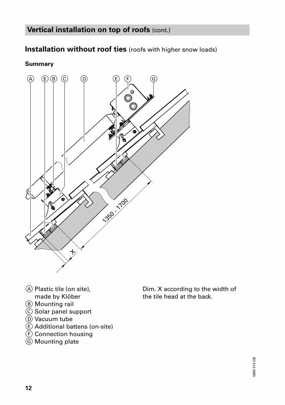
Installation without roof ties (roofs with higher snow loads)
Summary
A Plastic tile (on site),
made by Klöber
B Mounting rail
C Solar panel support
D Vacuum tube
E Additional battens (on−site)
F Connection housing
G Mounting plate
Dim.�X according to the width of
the tile head at the back.
58
62
�01
4�G
B
EE GDCBA F

13
Vertical installation on top of roofs (cont.)
Combination A
mm
B
mm
C
mm
D
mm
E
mm
F
mm
G
mm
H
mm
D20/D20 900 �� 600 900 �� 262.5 75 2�953
D20/D30 900 �� 600 1�800 900 262.5 75 3�663
D30/D30 1�800 900 300 1�800 900 113.0 74 4�372
Centre mounting rails when fitting one collector only.
58
62
�01
4�G
B

14
Vertical installation on top of roofs (cont.)
Fitting solar panel supports
58
62
�01
4�G
B
6
11.9.
3x25
3x25
6
qP
qP
7.
4.
8.
8.
7.
1.
4.
10.
15
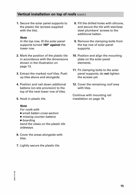
Vertical installation on top of roofs (cont.)
1. Secure the solar panel supports to
the plastic tile (screws supplied
with the tile).
Note
In the top row, fit the solar panel
supports turned 180��º against the
lower row.
2. Mark the position of the plastic tile
in accordance with the dimensions
shown in the illustration on
page�13.
3. Extract the marked roof tiles. Push
up tiles above and alongside.
4. Position and nail down additional
battens (on−site provision) to the
top of the next lower row of tiles.
5. Hook in plastic tile.
Note
For roofs with
� small batten cross−section
� missing counter battens
� boarding
bend the claws on the plastic tile
sideways.
6. Cover the areas alongside with
tiles.
7. Lightly secure the plastic tile.
�8. Fill the drilled holes with silicone,
and secure the tile with stainless
steel plumbers’ screws to the
additional batten.
�9. Remove the clamping bolts from
the top row of solar panel
supports.
10. Position and align the mounting
plate on the solar panel
elements.
11. Fit clamping bolts to the solar
panel supports; do not tighten
the screws yet.
12. Cover the remaining roof area
with tiles.
Continue with mounting rail
installation on page�18.
58
62
�01
4�G
B

16
Vertical installation on top of roofs (cont.)
Installation without roof ties (e.g. on sheet steel roofs)
Summary
A Mounting bracket
B Mounting rail
C Vacuum tube
D Connection housing
E Fixing plate
58
62
�01
4�G
B
EDCBA

17
Vertical installation on top of roofs (cont.)
Fitting mounting rails
*1When fitting several collectors side by side, maintain a clearance between the
mounting rails in accordance with the illustration on page�7 and 13.
Collector type A
mm
D20 800���1�000
D30 1�400���1�600
1. Secure the fixing plates and
brackets to the substrate in
accordance with the dimensions
shown in the illustration.
2. Secure the mounting rails with the
locking bolt to the fixing bracket.
Locking bolt must be turned 90º.
Continue with fitting the connection
housing on page�19.
58
62
�01
4�G
B
qT
qEqR
qWqO2. 1.
qI1.
qZ

18
Vertical installation on top of roofs (cont.)
Fitting mounting rails
*1When fitting several collectors side by side, maintain a clearance between the
mounting rails in accordance with the illustration on page�7 and 13.
1. Position the mounting rails with
tube supports on the mounting
plate; click the clamping bolts into
position, but do not tighten them
yet.
2. Position the mounting rails with
tube supports on the lower row of
roof ties or the solar panel
supports; click the clamping bolts
into position, but do not tighten
them yet.
58
62
�01
4�G
B
qO qQ
qI 1.
2.

19
Vertical installation on top of roofs (cont.)
Fitting the connection housing
Position the connection housing on
the mounting plate or the fixing
plates; click the clamping bolts into
position, but do not tighten them
yet.
Please note
The tube holders on the mounting
rail must be in line with those in the
connection housing. Where
necessary, align with a piece of
string.
Where several collectors are
installed side by side, continue with
fitting the connection housing on
page�44. Otherwise, continue with
fitting the connection set on page�46.
58
62
�01
4�G
B
qWqQ,
wE
20
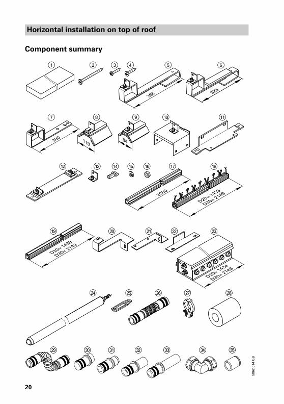
Horizontal installation on top of roof
Component summary
58
62
�01
4�G
B
eW eEeP eReQ eT
qI
1 2 3 4 5
7 8 9 qP
qW qE qT qUqR qZ
qO wWwQwP
wR wUwZwT
wO
wE
wI
6

21
Horizontal installation on top of roofs (cont.)
Roof tile integration
1 Batten 38���58��2�430�mm
Batten 30��100��2�430�mm
2 Zinc−plated countersunk chipboard
screw (Spax�s) 6���80�mm
3 Zinc−plated countersunk chipboard
screw (Spax�s) 5���30�mm
5 Roof tie with bracket
Roman tile cover
(higher snow loads)
qP Solar panel support with bracket
Plain tile integration
3 Zinc−plated countersunk chipboard
screw (Spax�s) 5��30�mm
6 Roof tie with bracket
Slate integration
4 Zinc−plated countersunk chipboard
screw (Spax�s) 6��30�mm
7 Roof tie with bracket
Corrugated roofing sheet integration
(profile�5, 6 and 8)
8 Roof tie with bracket for
corrugated roofing sheet
profile�5 and 6
9 Roof tie with bracket for
corrugated roofing sheet profile�8
Fixing without roof ties
e.g. on sheet steel roofs
Items�qQ to wE
For all types of roof cover
qQ Fixing plate
qW Fixing plate with 2�clamping bolts
qE Fixing bracket
qR Locking bolt
qT Washer
qZ Hexagon nut
qU Mounting rail 2�050�mm
qI Mounting rail with tube holders
qO Mounting rail with tube support
wP Retaining plate (U�shaped)
wQ Retaining plate
wW Spacer
wE Connection housing
wR Vacuum tube
wT Retaining rubber
Accessories for one panel array
� to 6�m2 absorber area
wZ Connecting pipe
wU Profile clip
wI Thermal insulation
� from 6�m2 absorber area
(adjacent collector arrays
connected in series)
wU Profile clip
wI Thermal insulation
wO Z�connecting pipe
eP Plug
eQ Plug with air vent valve
Connection set, comprising
wU Profile clip
eP Plug
or
eQ Plug with air vent valve
(only for water connection
from below)
eW Connecting pipe (short)
eE Connecting pipe (long)
eR Locking ring fitting
(elbow 90º), ∅�22�mm
eT Support sleeve
58
62
�01
4�G
B

22
Horizontal installation on top of roofs (cont.)
Installation with roof ties
Summary
A Mounting rail
B Roof tie
C Additional batten, 38��58�mm
(only for roof tile integration)
D Additional batten, 30��100�mm
(only for roof tile integration)
E Connection housing
Dim.�X according to the width of
the tile head at the back.
Dimension�A, see table on page�23.
58
62
�01
4�G
B
BA CD E C D

23
Horizontal installation on top of roofs (cont.)
Combination A
mm
B
mm
C
mm
D20 930���1�290 �� ��
D30 1�650���2�000 �� ��
D20/D20 930���1�290 1�470���1�700 2�490���2�800
D20/D30 930���1�290 1�470���1�700 3�110���3�500
D30/D20 1�650���2�000 2�180���2�420 3�110���3�500
D30/D30 1�650���2�000 2�180���2�420 3�740���4�220
58
62
�01
4�G
B

24
Horizontal installation on top of roofs (cont.)
Fitting roof ties for roof tile integration
1. Push up the roof tiles in
accordance with the dimensions
shown in the illustration on
page�22 and 23.
2. Secure the battens to the joists at
the head of the exposed rows of
tiles in accordance with the
dimensions shown in the
illustration on page�22.
3. Hook the roof ties into the battens
in accordance with the dimensions
shown in the illustration on
page�23.
4. Remove the drip tab and profiling
from the roof tiles in the area of
the roof ties.
5. Secure the roof ties and roof tiles.
Continue with fitting horizontal
mounting rails on page�31.
58
62
�01
4�G
B
3.
2. 5.
2
2
4.
35
1
1
30 x 100
38 x 58

25
Horizontal installation on top of roofs (cont.)
Fitting roof ties in the case of plain roof tile integration
1. Mark the position of the roof ties
in accordance with the dimensions
shown in the illustration on
page�23.
2. Remove tiles from the roof tie
location.
3. Hook the roof ties onto the
battens, locate and align on top of
the tile below.
4. Secure the roof ties to the battens.
5. Cover the roof; match tiles with an
angle cutter. Trim tiles approx.
35�mm.
Continue with fitting horizontal
mounting rails on page�31.
58
62
�01
4�G
B
62.
3.
3
4.

26
Horizontal installation on top of roofs (cont.)
Fitting roof ties for slate integration
1. Mark the position of the roof ties
in accordance with the dimensions
shown in the illustration on
page�23.
2. Remove slates from the roof tie
location.
3. Secure the roof ties to the roof face.
Utilise commercial lead flashing to
prevent the ingress of moisture.
4. Cover the roof.
Continue with fitting horizontal
mounting rails on page�31.
Fitting roof ties in the case of corrugated roofing sheet integration
1. Mark the position of the roof ties
in accordance with the dimensions
shown in the illustration on
page�23.
2. Position the roof ties at the level of
a batten onto the ridge of the plate
and drill a hole into the ridge of
the plate through the hole in the
roof tie.
3. Secure the roof ties with hexagon
woodscrews ∅�8�mm (on−site
provision) to the battens.
4. Secure the top of the roof ties and
mounting brackets.
Continue with fitting horizontal
mounting rails on page�31.
58
62
�01
4�G
B
7
4
2.
3.
3.3.
2.
4.
8,9

27
Horizontal installation on top of roofs (cont.)
Installation without roof ties (roofs with higher snow loads)
Summary
A Plastic tile (on site),
made by Klöber
B Mounting rail
C Solar panel support
D Connection housing
E Additional battens (on−site)
Dim.�X according to the width of
the tile head at the back.
58
62
�01
4�G
B
E
E
A BC D

28
Horizontal installation on top of roofs (cont.)
Combination A
mm
B
mm
C
mm
D
mm
E
mm
D20 �� 930���1�290 �� �� ��
D30 920���1�040 1�650���2�000 �� �� ��
D20/D20 �� 930���1�290 1�470���1�700 �� 2�490���2�800
D20/D30 �� 930���1�290 1�470���1�700 2�496���2�760 3�110���3�500
D30/D20 920���1�040 1�650���2�000 2�180���2�420 �� 3�110���3�500
D30/D30 920���1�040 1�650���2�000 2�180���2�420 3�110���3�500 3�740���4�220
58
62
�01
4�G
B

29
Horizontal installation on top of roofs (cont.)
Fitting solar panel supports
1. Secure the solar panel supports to
the plastic tile (screws supplied
with the tile).
2. Mark the position of the plastic tile
in accordance with the dimensions
shown in the illustration on
page�28.
3. Extract the marked roof tiles. Push
up tiles above and alongside.
4. Position and nail down additional
battens (on−site provision) to the
top of the next lower row of tiles.
5. Hook in plastic tile.
Note
For roofs with
� small batten cross−section
� missing counter battens� boarding
bend the claws on the plastic tile
sideways.
6. Cover the areas alongside with tiles.
7. Lightly secure the plastic tile.
8. Fill the drilled holes with silicone,
and secure the tile with stainless
steel plumbers’ screws to the
additional batten.
9. Cover the remaining roof area
with tiles.
Continue with fitting horizontal
mounting rails on page�31.
58
62
�01
4�G
B
6
3x25
6
3x25
8.
7.
1.
8.
4.
4.
7.
1.
qP
qP

30
Horizontal installation on top of roofs (cont.)
Installation without roof ties (e.g. on sheet steel roofs)
Summary
Collector type A
mm
D20 930���1�290
D30 1�650���2�000
A Mounting bracket
B Mounting rail
C Connection housing
58
62
�01
4�G
B
CBA

31
Horizontal installation on top of roofs (cont.)
Fitting horizontal mounting rails
1. Secure the fixing brackets to the
substrate in accordance with the
dimensions shown in the
illustrations.
2. Secure the mounting rails to the
fixing bracket.
Locking bolt must be turned 90º.
Continue with fitting the connection
housing on page�32.
Fitting horizontal mounting rails
Secure the mounting rails with
brackets to the roof ties or solar
panel supports; maintain dimension
170�mm on the side of the
connection housing.
58
62
�01
4�G
B
qUqRqEqTqZ
2.1.
qU
56, 7, 8, 9, qP,
0

32
Horizontal installation on top of roofs (cont.)
Fitting the connection housing
1. Position the fixing plate as a
drilling template onto the bottom
of the connection housing (50�mm
from the outside edge), and drill
holes A with a ∅�8.5�mm bit.
Note
Locking bolts must be turned 90�º.
2. Secure the fixing plate flush with
the lower mounting rail.
3. Secure the fixing plate flush with
the upper mounting rail.
4. Click the connection housing into
the clamping bolts.
5. Secure the connection housing
with locking bolts to the fixing
plates.
Do not tighten the screws yet.
58
62
�01
4�G
B
50
AwE qQ
A

33
Horizontal installation on top of roofs (cont.)5
86
2�0
14
�GB
qU
qT
qZ
qT
qW
qZ
qUwE
qR
qR
4.
5.
3.
2.

34
Horizontal installation on top of roofs (cont.)
Fitting vertical mounting rails
58
62
�01
4�G
BqI
qR
qO
qE
qQqW
qO
qI
wQ
wP
qZ
qT
qU
3x
2.
4.
5.
3.
6.
qU
1.

35
Horizontal installation on top of roofs (cont.)
Please note
Locking bolts must be turned 90�º.
1. Secure the fixing brackets to the
mounting rails in accordance with
the dimensions shown.
2. Secure the mounting rails to the
fixing bracket.
3. Secure the retaining plate
(U�shaped) to the lower mounting
rail.
4. Slide the mounting rail with the
tube holders into the retaining
plate.
Please note
The tube holders on the mounting
rail must be in line with those in
the connection housing. Where
necessary, align with a piece of
string.
5. Push the locking bolt through the
slot in the plate into the mounting
rail with the tube holders, and
secure the retaining plate.
6. Secure the retaining plate to the
mounting rail.
If a second collector is fitted above
the first:
Secure spacers to the top and
bottom of the fitted mounting rails.
Continue as described above.
Tighten all clamping bolts.
Continue with connecting the
connection housing on page�44.
58
62
�01
4�G
B
wW

36
Installation on flat roofs
Component summary
58
62
�01
4�G
B
eW eEeP eReQ eT
1 2 3 4 5 6 7 qI
qO wE wR
wT wZ wU wOwI

37
Installation on flat roofs (cont.)
1 Fixing plate with 2�clamping bolts
2 Mounting bracket
3 Rawl plug S�10
4 Washer
5 Hexagon screw 8��70�mm
6 Locking bolt
7 Hexagon nut
qI Mounting rail with tube holders
qO Mounting rail with tube support
wE Connection housing
wR Vacuum tube
wT Retaining rubber
Accessories for one panel array
� to 6�m2 absorber area
wZ Connecting pipe
wU Profile clip
wI Thermal insulation
� from 6�m2 absorber area
(adjacent collector arrays
connected in series)
wU Profile clip
wI Thermal insulation
wO Z�connecting pipe
eP Plug
eQ Plug with air vent valve
Connection set, comprising
wU Profile clip
eP Plug
eW Connecting pipe (short)
eE Connecting pipe (long)
eR Locking ring fitting
(elbow 90º), ∅�22�mm
eT Support sleeve
58
62
�01
4�G
B

38
Installation on flat roofs (cont.)
Installation
Secured against slippage
Installation height
above ground
m up to 8 8 to 20 20 to 100
Weight of supports Type
D20
Type
D30
Type
D20
Type
D30
Type
D20
Type
D30
per support�A*1
per support�B*1kg
kg
22
26
33
39
44
46
65
69
66
67
98
101
Secured against lifting
Installation height
above ground
m up to 8 8 to 20 20 to 100
Weight of supports Type
D20
Type
D30
Type
D20
Type
D30
Type
D20
Type
D30
per support�A*1
per support�B*1kg
kg
15
18
22
27
31
32
46
49
48
48
72
73
*1For supports, see drawing on page�39.
When fitting several collectors side by side, maintain a clearance between the
mounting rails in accordance with the illustration on page�7.
1. Position supports on a solid
foundation on protective mats;
ensure that the collector array can
be oriented towards south
(longitudinal tube axis aligned
east−west).
2. Secure the fixing brackets to
supports�B in accordance with
the dimensions shown (screws
provided on site).
3. Secure the fixing brackets to
supports�A in accordance with
the dimensions shown (screws
provided on site).
4. Secure the mounting rails to the
fixing bracket.
Locking bolt must be turned 90º.
5. Position the connection housing
on the fixing plates; click the
clamping bolts into position and
tighten them.
Please note
The tube holders on the mounting
rail must be in line with those in
the connection housing. Where
necessary, align with a piece of
string.
Where several collectors are
installed, continue with connecting
the connection housing on page�44.
Otherwise, continue with fitting the
connection set on page�46.
58
62
�01
4�G
B

39
Installation on flat roofs (cont.)
A Support�A
B Support�B
C Clamping bolt
Collector type A
mm
D20 930���1�290
D30 1�650���2�000
58
62
�01
4�G
B
3
A
wE
qO
5
4
2
3
qI
6
742B
15
4
2
4.
2.
3.
5.
4.

40
Installation on walls
Component summary
58
62
�01
4�G
B
eW eE eReQ eT
1 2 3 4 5 6 7 8
qI qO wE
wR wT wZ wU wI
wO eP

41
Installation on walls (cont.)
1 Fixing plate with 2�clamping bolts
2 Mounting bracket
3 Rawl plug S�10
4 Washer
5 Hexagon screw 8��70�mm
6 Locking bolt
7 Hexagon nut
8 Locking profile
qI Mounting rail with tube holders
qO Mounting rail with tube support
wE Connection housing
wR Vacuum tube
wT Retaining rubber
Accessories for one panel array
� to 6�m2 absorber area
wZ Connecting pipe
wU Profile clip
wI Thermal insulation
� from 6�m2 absorber area
(adjacent collector arrays
connected in series)
wU Profile clip
wI Thermal insulation
wO Z�connecting pipe
eP Plug
eQ Plug with air vent valve
Connection set, comprising
wU Profile clip
eP Plug
or
eQ Plug with air vent valve
(only for water connection
from below)
eW Connecting pipe (short)
eE Connecting pipe (long)
eR Locking ring fitting
(elbow 90º), ∅�22�mm
eT Support sleeve
58
62
�01
4�G
B

42
Installation on walls (cont.)
Installation
Collector type A
mm
D10 450�����645
D20 800���1�000
D30 1�400���1�600
58
62
�01
4�G
B
3
2.
3.
4.
5.
2
1.
3.
6 47
qI
1
647
8
wEqO

43
Installation on walls (cont.)
When fitting several collectors, maintain a clearance between the mounting
rails in accordance with the illustration on page�7.
1. Secure the fixing brackets to the
wall in accordance with the
dimensions shown (screws
provided on site).
2. Secure the fixing plates to the wall
in accordance with the dimensions
shown (screws provided on site).
3. Secure the mounting rails to the
fixing bracket.
Locking bolt must be turned 90º.
4. Position the connection housing
on the fixing plates; click the
clamping bolts into position and
tighten them.
Please note
The tube holders on the mounting
rail must be in line with those in
the connection housing. Where
necessary, align with a piece of
string.
5. Secure the locking profile with the
locking bolt to the mounting rails.
Locking bolt must be turned 90º.
Where several collectors are
installed above each other, continue
with connecting the connection
housing on page�44. Otherwise,
continue with fitting the connection
set on page�46.
58
62
�01
4�G
B

44
Water connections
Connecting the connection housing
Interconnecting pipes must be free from damage and contamination.
Lubricate all plug−in joints (O�ring seals) on the collectors only with the
special grease supplied with the connection set.
Up to 6�m2 absorber area
A Flared coupling
B Groove for profile clip
1. Insert the interconnecting pipes
into the flow and return
connectors.
2. Push the second connection
housing carefully against the first
and insert the interconnecting
pipes.
3. Fit the profile clips onto the flared
coupling and the interconnecting
pipes to secure the assembly.
4. Secure the connection housing.
5. Cut the thermal insulation
longitudinally, fit it and join its cut
faces with adhesive.
58
62
�01
4�G
B
wZA wIwU wEB
2.
3.
1.
5.

45
Water connections (cont.)
From 6�m2 absorber area
(where collector arrays installed side by side are connected in series)
A Flared coupling
B Groove for profile clip
1. Insert the interconnecting pipe
into the flow connector.
2. Insert drain plugs into the return
connector.
3. Push the second connection
housing carefully onto the first,
and insert the interconnecting
pipe into the return connector.
4. Insert the plug with air vent valve
into the flow connector of the
second connection housing.
5. Fit the profile clips onto the flared
coupling and the interconnecting
pipes or plug to secure the
assembly.
6. Secure the connection housing.
7. Cut the thermal insulation
longitudinally, fit it and join its cut
faces with adhesive.
58
62
�01
4�G
B
A eP B eQ wEwU
3.2.
5.
4.
7.
1.
wO

46
Water connections (cont.)
Fitting the connection set
A Flared coupling
B Groove for profile clip
C Return connector; to collector
D Flow connector; to DHW cylinder
58
62
�01
4�G
B
5.
wEeQ ePDwU
3.
1.
eTeReE
2. 4.
C
A EWD
B

47
Water connections (cont.)
When assembling the locking ring
fitting, observe the following:
� All pipe ends must be square and
deburred.
� Push the union nut and the locking
ring onto the pipe and lightly
lubricate the threads with oil.
� Push the pipe into the compression
fitting as far as it will go.
� Initially turn the union nut by hand,
then tighten with an open ended
spanner by a further ¾ turn.
Do not use annealed copper pipes
with compression fittings.
1. Insert the plug or plug with air
vent valve until they bottom out.
Please note
Use the plug with air vent valve,
if the water connections from
the collector array are routed
downwards.
2. Insert the connecting pipes until
they bottom out.
3. Fit the profile clips onto the flared
coupling, plugs and pipes to
secure the assembly.
4. Thread the locking ring fittings
onto the connecting pipe.
5. Insert into the support sleeves of
the solar circuit pipes.
Make the connection between the
panel array and the solar circuit
fittings.
6. Tighten all clamping bolts and
screws.
58
62
�01
4�G
B

48
Water connections (cont.)
Fitting vacuum tubes and collector temperature sensor
¨�Safety instruction
Wear gloves and safety goggles to prevent burns and injuries.
A Flow connection
B Return connection
C Adhesive tape
D Template
Wall Pitched roof Flat roof
58
62
�01
4�G
B
wT wR A CB
4.
6.
2.
qI
7.
3.
8.
D
5.

49
Water connections (cont.)
¨�Safety instruction
Only rotate the vacuum tubes with locking ring released. Otherwise there is a
risk of breakage.
1. Open the connection housing and
remove the thermal insulation
mat.
2. Remove the protective cap from
the vacuum tubes.
3. Click the vacuum tubes into the
tube holders on the mounting rails
until they bottom out inside the
coupling. Ensure no part of the
thermal insulation is pinched in
the process.
4. For roofs with deviations from due
south:
Adjust the angle of inclination of
the vacuum tube absorber using
the template supplied by turning
the tubes around their own axis
(coated side of the absorber
oriented towards the sun).
5. Initially tighten the locking ring
fitting by hand. For this, hold the
soldered hexagon nut with an
open ended spanner�SW�17. Then
tighten the locking ring fitting by
1½ turns.
6. Secure the vacuum tubes with the
retaining rubber.
7. Fit the collector temperature
sensor in the connection housing
position that is furthest west.
Insert the sensor into the holder
until it bottoms out. Route the
sensor lead in the recess of the
thermal insulation and secure with
adhesive tape.
8. Secure the sensor with PG thread
onto the casing.
9. Carefully position the thermal
insulation mat and close the
connection housing.
58
62
�01
4�G
B

50
Installation
¨�Safety instruction
Use only gunmetal and brass fittings and copper pipes for the installation.
Never use galvanized pipes, galvanized fittings or graphitised gaskets. Use
hemp only in conjunction with pressure and temperature resistant sealants
(e.g. Viscotex�Solarpaste, Locher, CH�9450�Altstätten).
Never step onto solar panels. Never solder near or on the collector.
A Collector
B Solar�Divicon
C Collecting container
D Expansion vessel
E Manual solar fill pump
F Filling point
G Shut−off valve
H Drain
K Fill valve assembly (F, G, H)
L DHW cylinder
M Air separator
N Solar control unit
O Air vent valve
58
62
�01
4�G
B
VL RL
T T
T
T
A
L K
O
BN
M
G
H
E
D C
F
R
G

51
Installation (cont.)
1. Route pipes so that they can be
completely vented. Install at least
one air vent valve at the highest
point of the system. Install an air
separator at an accessible point in
the pipework (see fig. on page�50).
2. Equip the system to EN�12�975
with expansion vessel, safety
valve and circulation pump.
3. The expansion vessel must be
approved to DIN�4807, and must
be arranged with a heat insulating
loop.
The diaphragms and seals of the
expansion vessel and the safety
valve must be suitable for the
process medium.
For the calculation of the
inlet pressure, see the
service instructions.
4. When operating without
Solar−Divicon, use only safety
valves designed for a max. of
120�ºC and 6�bar bearing the
marking "S" (solar) as part of the
component identification.
5. Make all unions pressure and
temperature resistant (observe
the max. standby temperature of
the solar panel).
For commissioning of
the solar heating system,
see service instructions.
58
62
�01
4�G
B

Viessmann Werke GmbH�&�CoD�35107 AllendorfTel: +49 6452 70�0Fax: +49 6452 70�27�80www.viessmann.de
Viessmann LimitedHortonwood 30, TelfordShropshire, TF1 7YP, GBTel: +44 1952 675000Fax: +44 1952 675040E−mail: info−[email protected]
52
5862�0
14�G
B���S
ub
ject to
tech
nic
al m
od
ific
ati
on
s.
Pri
nte
d o
n e
nvir
on
men
tally f
rien
dly
,
chlo
rin
e−f
ree b
leach
ed
pap
er