System configuration 5. System configuration -...
34
21 System configuration ECAS 5. 5. System configuration ECAS is an extremely variable system that can be adapted to meet the requirements of the vehicle with great efficiency. Up to 3 base control loops may be present in the vehicle. In addition, it is possible to control a lifting axle. The selection of the system components to be used is determined by how the vehicle manufacturer expects the system to perform. To illustrate this further, the following pages show different control circuits for the complete vehicle combination. For ABS or EBS, the configuration can be determined on the basis of the speed sensors/modulators installed in the system (e. g. 4S/3M); In ECAS, on the other hand, it is the number of basic control circuits for level control which determine the configuration. This number corresponds to the number of distance sensors installed. A system with two distance sensors, for example, is therefore referred to as a 2-point control system. The specification of the type of control may apply to all sections of the vehicle (as shown here) or to the components of a single axle. A vehicle with full air suspension and 3-point control, for example, consists of the steered axle with 1-point control and a driving axle with 2-point control. Generally, the following control types are found in vehicles: • 1-point control • 2-point control • 3-point control Looked at axle by axle, 1-point control is found on steered front axles and on rear axles. In vehicles with partial air suspension, the driving axle is sensed by a distance sensor for 1-point control. 2-point control is used in cases where irregular or uneven loading is expected in vehicles with a large tyre tread width, or in vehicles with a high centre of gravity. Even from an overall vehicle perspective, a 2-point control is also evident in vehicles with full air suspension where front and rear axles are equipped with one distance sensor each. 3-point control is only found in vehicles with full air suspension and denotes the combination of 1-point control on the steered front axle and 2-point control on the rear axle. ECU Distance sensor RA ECU Distance sensor RA Solenoid valve Driving axle Distance sensor left right RA RA Solenoid valve Driving axle left right 1-point control 2-point control Abb. 13 Control for vehicles with partial air suspension
Transcript of System configuration 5. System configuration -...

21
System configuration ECAS 5.
5. System configurationECAS is an extremely variable system that can be
adapted to meet the requirements of the vehicle with
great efficiency. Up to 3 base control loops may be
present in the vehicle. In addition, it is possible to control
a lifting axle. The selection of the system components to
be used is determined by how the vehicle manufacturer
expects the system to perform.
To illustrate this further, the following pages show
different control circuits for the complete vehicle
combination.
For ABS or EBS, the configuration can be determined on
the basis of the speed sensors/modulators installed in the
system (e. g. 4S/3M); In ECAS, on the other hand, it is the
number of basic control circuits for level control which
determine the configuration. This number corresponds to
the number of distance sensors installed. A system with
two distance sensors, for example, is therefore referred
to as a 2-point control system.
The specification of the type of control may apply to all
sections of the vehicle (as shown here) or to the
components of a single axle. A vehicle with full air
suspension and 3-point control, for example, consists of
the steered axle with 1-point control and a driving axle
with 2-point control.
Generally, the following control types are found in
vehicles:
• 1-point control
• 2-point control
• 3-point control
Looked at axle by axle, 1-point control is found on
steered front axles and on rear axles. In vehicles with
partial air suspension, the driving axle is sensed by a
distance sensor for 1-point control.
2-point control is used in cases where irregular or
uneven loading is expected in vehicles with a large tyre
tread width, or in vehicles with a high centre of gravity.
Even from an overall vehicle perspective, a 2-point
control is also evident in vehicles with full air suspension
where front and rear axles are equipped with one
distance sensor each.
3-point control is only found in vehicles with full air
suspension and denotes the combination of 1-point
control on the steered front axle and 2-point control on
the rear axle.
ECU
Distance sensor
RA
ECU
Distance sensor
RA
Solenoid valve
Driving axle
Distance sensor
left right RARA
Solenoid valve
Driving axle
left right
1-point control 2-point control
Abb. 13 Control for vehicles with partial air suspension
22
System configuration5. ECAS
The particular distance sensor configuration can be
extended if there is a lifting axle with pressure switches
or pressure sensors.
It is sufficient to fit pressure switches that determine the
bellows pressure for the automatic lowering of the lifting
axle when certain fixed pressure values are reached in
the driving axle's support bellows. Pressure switches can
also be used to implement a traction help function.
Pressure sensors are used on the driving axle whenever
a fully automatic lifting axle, tyre impression
compensation, or the overload function is required. If
pressure ratio control or optimum traction control is
required, then additional pressure sensors have to be
fitted to the lifting axle supporting bellows.
ECU
Distance sensor
ECU
Solenoid valve
Front axle
Distance sensor
Distance sensor
Distance sensor
Distance sensor
solenoidvalve Driveaxle
solenoidvalve steeringaxle
FARA
left
right
left
right
RARA
Solenoid valve
Driving axle
left right
FAFAleft right
2-point control 3-point control
Abb. 14 Control for vehicles with full air suspension

23
Components ECAS 6.
6. Components
Components of an ECAS System
• Distance sensor(s),
• Pressure switch,
• Pressure sensor(s)
(optional): (The use of pressure switches or pressure
sensor(s) is optional, i.e. it depends on the selected
system variant.)
• Control unit (ECU)
• ECAS solenoid valve(s)
• Remote control unit (optional)
• Pneumatic components (air suspension bellows;
possibly lifting bellows; pressure limiting valves;
pipes; compressed air reservoir).
The pneumatic components are not dealt with here since
they correspond to the pneumatic components in a
conventional air suspension system and do not require
any particular explanation in the context of ECAS. The
electrical power supply will be dealt with separately as
part of the description of the ECAS electronic electronic
system.
6.1 Sensors
The starting point of the control process is the sensor.
These sensors pick up the quantities to be controlled,
and transmit them to the ECU via the sensor cable.
You must always install at least one distance sensor
in the ECAS system.
Pressure switches or pressure sensor(s) are used for
controlling additional functions.
6.1.1 Distance sensor
The distance sensor 441 050 0.. 0 is used as an actual
value transmitter for continuous detection of changes in
height. The inductive measuring principle is used.
A slewing motion is transferred to the inside of the sensor
by a lever. This movement is translated, following crank
mechanism logic, without play into a linear movement of
the armature in the coil. The 'dipping movement' of the
ferro-magnetic armature into the stationary coil causes a
phase displacement between current and voltage. The
ECU receives these signals and converts them into count
values.
For the angle-of-rotation sensor 441 050 1.. 0, the
change in inductance is generated by the rotary
movement of the sensor shaft.
It is not possible to test the distance sensor function
using a voltage meter.
Abb. 15 Distance sensor 441 050 0.. 0 and lever 441 050 718 2
Abb. 16 Sectional view of the distance sensor 441 050 0.. 0
!
!
Sensor shaft
Sensor lever
Lever guide
Sensor lever
Sensor shaft
+Lifting
Lowering-
Cylindrical coil
Armature
Lever guide
Sensor shaft

24
Components6. ECAS
Abb. 17 Angle-of-rotation sensor 441 050 1.. 0
Abb. 18 Diagram of the angle-of-rotation sensor 441 050 1.. 0
If the distance sensor needs to be checked, the
resistance can be measured to verify proper function of
the coil. The resistance must be approx. 120 ohm. The
coil's induction is evaluated more than 50 times a second
by a special evaluation circuit within the ECU. The ECU
also monitors the sensor for proper function.
The distance sensor is located on the vehicle frame near
the axle whose air suspension bellows are to be
controlled.
A distance sensor (1-point control) is usually installed
above the centre of the steering axle. Driving axles may
also be equipped with 2 distance sensors as an
alternative to the single sensor variant.
– Install the sensors so that they lie as far apart from
one another as possible to achieve optimal controlling
action of the individual distance sensors (2-point
control on one axle).
The distance sensor is permanently linked to the axle to
be controlled by means of a linkage. The rod has rubber
end pieces acting as dampers and compensators.
The type of sensors installed must be set in the
parameters (optional parameter 2.5).
The ECAS ECU converts the respective sensor value
into counts, i.e. into a byte value between 4 and 255
counts. More recent ECAS ECUs have been changed to
16 bit processing. The sensor values are here specified
as timer ticks (range from 256 to 65.536).
Installation note
The distance sensor has a measuring range between
+ 43° and - 40° (initial position 90°, lever is level). Fig. 16
shows the assignment of positive and negative ranges.
The entire deflection range is most efficiently used when
the lever is almost horizontal at normal level.
The maximum deflection of the lever (+/- 50°) may
not be exceeded.
The length of the sensor lever is selectable. However,
the length must be identical for all distance sensors on an
axle.
Short sensor lever
A short sensor lever ensures a high resolution of the
measured values even when the change in the height is
slight. However, it can only cover a small range of
settings.
Long sensor lever
A long sensor lever covers a wide range of settings at the
expense of the resolution of measured values. The
objective is the best possible utilisation of the deflection
angle.
Cranking of the lever must be avoided because this
might result in impermissible tilting torques acting on
the sensor shaft. For this reason, all swivelling axles
must be aligned in parallel.
The distance sensor only exists in one variant for
installation on the right and left-hand sides.
The sensor level can, however, be mounted in steps of
90 degrees on the sensor shaft which can be turned in
the sensor housing without stops. For accurate operation
and accurate measured value acquisition, the sensor
shaft must be properly aligned.
ferromagnetic core
plastic axle
coil
ferromagneticsheet metal
!
!

25
Components 6.ECAS
To facilitate this process, two projections (↑ Fig. 16)
functioning as lever guides have been provided on the
sensor shaft.
These projections point toward the right at right angles
relative to the direction of armature movement (as shown
in the illustration). This permits the best possible
utilisation of the distance sensor's measuring range.
It is important that the distancesensor lever moves
freely across the whole of its setting range, and that
the lever can only move within that range (i.e. does
not overshoot).
When mounting the distance sensor on the vehicle body,
take the sensor's raising and lowering reaction into
account:
• Immersion of the cylinder coil in the LIFT direction
increases the induction.
• Retraction of the cylinder coil in the LOWER direction
reduces the induction.
The acquired measured values can be displayed on
suitable diagnostic equipment (PC).
• Raising the vehicle body also increases the displayed
values.
• Lowering the vehicle body reduces them.
Distance sensor information for service purposes
6.1.2 Pressure switch
Abb. 19 Pressure Switch 441 014 … 0
Pressure switches are used to permit simple extended
ECAS functions (lifting axle control, traction help) in
systems operating according to the pressure equalising
principle.
Two pressure sensors, designed as an NCC, sense the
support bellows pressure. In unladen condition, the
pressure switches are connected to terminal 15 via two
corresponding pins on the ECAS electronic control unit.
A pressure switch (with a switching point, for example, of
e. g. 11 … 11.5 t) transmits a signal to the ECU when the
axle load is above or below the normally permitted level.
The lifting or trailing axle is controlled in driving operation
on the basis of this information. Dynamic influences on
the axle load are ruled out by selecting a certain length of
time (e .g. 2 or more seconds) during which the change
in switch position must be maintained in order to trigger
an axle response.
The 2nd pressure switch (switching point: e. g. 13 t)
transmits a signal to the ECU when the permissible axle
load with activated traction help is exceeded. Axle load
distribution during activated traction help is controlled in
accordance with this information.
The advantage of using a normally closed contact is that
the lifting axle is always lowered / the load is always
transferred to the trailing axle when there is no voltage
Order Number Design
441 050 006 0 Bayonet; without lever; used by MAN, DAF and as replacement.
441 050 007 0 slim housing; M24x1 thread; used by Renault (cars);
441 050 008 0 M24x1; without lever; used by DC, DAF, MAN, RVI, Scania, other manufacturers (replacement for 441 050 003 0)
441 050 010 0 M27x1; without lever; used by RVI, Neoplan and in trailers
441 050 011 0 Bayonet DIN 72585-A1-2.1-Sn/K2; without lever; used by MAN, IVECO, Scania, DAF and in trailers
441 050 012 0 Bayonet DIN 72585-A1-2.1-Sn/K2; without lever; without temperature compensation; MAN TGA, DC Actros and Atego
441 050 013 0 as for 441 050 012 0, without colour coding on the electrical connection however; used by RVI
441 050 100 0 Angle of rotation sensor; bayonet DIN 72585-A1-2.1-Sn/K2; without temperature compensation; straight lever; used by DAF
441 050 101 0 Angle of rotation sensor; bayonet DIN 72585-A1-2.1-Sn/K2; without temperature compensation; straight lever; used by DAF
!
441 050 120 0 Angle of rotation sensor; bayonet DIN 72585-A1-2.1-Sn/K2; without temperature compensation; cross lever; used by IVECO
441 050 121 0 Angle of rotation sensor; bayonet DIN 72585-A1-2.1-Sn/K2; without temperature compensation; cross lever; used by DC
441 050 122 0 Angle of rotation sensor; bayonet DIN 72585-A1-2.1-Sn/K2; without temperature compensation; cross lever; used by SCANIA Bus
441 050 123 0 Angle of rotation sensor; bayonet DIN 72585-A1-2.1-Sn/K2; without temperature compensation; cross lever; used by MAN
Order Number Design

26
ComponentsECAS6.
(i. e. the ignition is OFF). As a result, overloading can be
excluded.
6.1.3 Pressure sensor
Pressure sensors are required in order to use the
extended ECAS functions. In the simplest variant, the
pressure sensor senses the pressure in one bellows on
the driving axle.
This arrangement is selected for the simple control tasks:
• Control of the lifting axle,
• control of traction help, or
• to compensate tyre impression
For complicated control functions, e. g. pressure ratio
control, every supporting bellows has a sensor, including
the lifting axles.
The pressure is measured by means of extension
measuring strips. As the pressure is increased, the
resistance at a Wheatstone bridge changes; this change
generates a voltage in proportion to the pressure.
Depending on the design, the pressure sensor is
supplied with 8 … 32 V. The voltage indicating the
pressure is transmitted to the ECU via a signal line
(sensor cable).
In a pressureless condition (pressure sensor offset), the
output is 0.5 V.
The transmittable voltage at the upper limit of the
measuring value at a pressure of 10 bar is 4.5 V
(pressure sensor type with bayonet connector to DIN 72
585-A1-3.1 - DIN bayonet that is) or 5.5 V (pressure
sensor type with bayonet - older version).
The maximum permitted pressure of 16 bar for these
pressure sensors may not be exceeded.
The output of measuring values is digital, i. e. in steps.
The acquired measured values can be displayed on
suitable diagnostic equipment (PC).
The pressure sensor is connected to a separate
connector on the supporting bellows or on a T-piece on
the bellows' inlet port.
The pressure sensor should never be fitted in the
compressed air line between the supporting
bellows and the ECAS solenoid valve. Measuring
errors may be caused by the extreme dynamics of
constant charging and venting actions.
Abb. 20 Pressure sensor 441 040 003 0
The pressure sensor with Schlemmer bayonet
connection for the sensor cable. The smallest digital
measuring steps are 1/20 bar. 1 1 bar would equal 20
measuring values. This type of pressure sensor is
increasingly being replaced by the type described below.
.
Abb. 21 Pressure sensor 441 040 0.. 0
The pressure sensor is equipped with a DIN bayonet
connection for the sensor cable. The smallest digital
measuring steps are 1/16 bar. 1 bar would equal 16
measuring values. This type of pressure sensor is used
more and more frequently in vehicle systems (also if EBS
is installed) because of its standardised DIN connection
and will replace the variant described above.
The same applies to replacing a pressure sensor which
with a Schlemmer bayonet connection.
The replacement of the two types of pressure sensors
requires some attention. If a replacement becomes
necessary, the parameters in the electronic system
affecting pressure-related control processes must be
modified.
Pressure sensor information for service purposes
!
Order Number Design
441 040 003 0 pneum. connection M16x1.5; electr. connection bayonet; 500mV/bar; only replacement DAF and trailers.
441 040 004 0 pneum. connection M16x1.5; electr. connection M27x1; 500mV/bar; only replacement DAF.
441 040 005 0 pneum. connection M16x1.5; O-ring seal; electr. connection M 27x1; 500mV/bar; only replacement RVI.
441 040 013 0 pneum. connection M16x1.5; bayonet DIN 72585-A1-3.1-Sn/K2; 400mV/bar; ratio version; used by DC, MAN, DAF, IVECO and trailers; replacement for variant 007

27
Components ECAS 6.
6.2 Electronic Control Unit (ECU)446 055 … 0
The ECU is the heart of the ECAS system. The ECAS
electronic system is supplied with power via terminal 15
(ignition). In addition, supply via terminal 30 (steady
positive voltage) is possible. In this respect, it is decisive
which system is used.
The control process for the air suspension is coordinated
in the ECAS ECU. That means:
• All incoming signals from the distance sensors are
continuously monitored, converted into computer-
legible signals (counts or timer ticks) and evaluated.
• In systems with pressure switches fitted, lifting axle
control is initiated relative to the pressure switch
position.
• If the system configuration includes a pressure
sensor, these incoming signals are also continuously
monitored, converted into computer-legible signals
(counts), and evaluated.
• In correspondence with the parameters settings, and
the design of the system, the signals for controlling
the nominal values in the air suspension bellows are
determined and transmitted to the ECAS solenoid
valves.
• All data for which parameters have been set, which
have been calibrated, or are otherwise defined (e.g.
memory levels), are stored and managed.
• Any messages are recorded, stored and displayed via
the signal lamp on the instrument panel if applicable.
They can be read out using the appropriate software.
• The electronic control unit stores the parameters
which determine how the specific system functions.
The vehicle manufacturer specifies the parameters
during initial start-up; the parameters are only allowed
to be changed with the manufacturer's approval and
after a training course has been completed.
• The data exchange with the remote control unit is
maintained and certain monitoring functions are
performed.
In order to ensure swift control reactions to any changes
in actual values, the micro-processor runs through a
programme cycle within fractions of second
(25 milliseconds). One programme cycle performs all the
tasks described above. This programme is permanently
written into a program module (ROM). However, it uses
numerical values (parameter) which are stored in a
programmable memory. These parameters affect the
computing operation and thus the control reactions of the
ECU. They are used to transmit the system configuration
and the other preset values concerning the vehicle and
functions to the computer programme.
The electronic control unit may be located in a wide
range of different positions on or in the vehicle. The
majority of vehicle manufacturers prefer to accommodate
it in the area of the glove compartment, although
electronic control units have already been positioned
under the seat (DAF) or in the driver's door (SCANIA).
For the diagnosis it is important to know the
installation position, especially with regard to older
generations, so that the diagnostic interface can be
inserted between the electronic control unit and the
25 or 35-pin connecting plug.
In newer systems, the electronic control unit can be
addressed via a central diagnostic interface.
The large number of different ECAS generations, air
suspension systems and rationalisation (i.e. ratio) levels
leads to a wide variety of ECAS electronic control units in
the towing vehicle sector.
Below is a classification of ECAS electronic systems:
- ECAS 1st generation without pressure sensor
- ECAS 1st generation with pressure sensor
- ECAS 4x2 A
- ECAS 6x2 A
- ECAS 4x2 (Ratio)
- ECAS 4x2 (Ratio) KWP 2000
441 040 014 0 pneum. connection M16x1.5; bayonet DIN 72585-A1-3.1-Sn/K2; 333mV/bar; 12 bar measuring range; used by IVECO-S2000
441 040 015 0 pneum. connection M16x1.5; Raufoss O-ring seal; bayonet DIN 72585-A1-3.1-Sn/K2; 400mV/bar; used by IVECO (from December 2000).
441 040 017 0 pneum. Connection M16x1.5; bayonet DIN 72585-A1-3.1-Sn/K2; 400mV/bar; with Gore filter; used by Scania (from January 2001) is replaced by 441 044 105 0
441 040 018 0 pneum. connection M16x1.5; O-ring seal; bayonet DIN 72585-A1-3.1-Sn/K2; 400mV/bar; used by RVI.
441 044 001 0 pneum. connection M16x1.5; bayonet DIN 72585-A1-3.1-Sn/K2; 400mV/bar; used by DAF, DC, MAN.
441 044 002 0 pneum. connection M16x1.5; Raufoss O-ring seal; bayonet DIN 72585-A1-3.1-Sn/K2; 400mV/bar; used by IVECO.
441 044 003 0 pneum. connection M16x1.5; bayonet DIN 72585-A1-3.1-Sn/K2; 333mV/bar; used by Scania Bus.
441 044 105 0 pneum. connection M16x1.5; bayonet DIN 72585-A1-3.1-Sn/K2; 400mV/bar; used by Scania
Order Number Design
!

28
ComponentsECAS6.
- ECAS 6x2 (Ratio)
- ECAS 6x2 DV (= Pressure ratio control)
- ECAS 4x2/6x2 CAN 1
- ECAS 4x2/6x2 CAN 2
- ECAS + ESAC (with and without CAN)
6.2.1 ECAS 1st generation without pressure
sensor
This ECU represents the first generation of ECAS and is
used for controlling 4x2 or 6x2 vehicles with partial or full
air suspension. The lifting or trailing axle function for 6x2
vehicles can only be controlled using pressure switches
in this case.
Abb. 22 ECU 446 055 003 0
An external characteristic feature of an electronic control
unit of this type is the aluminium housing into which the
printed circuit board with the 35-pin terminal strip is
pushed from the back and to which it is then crimped.
This group now only includes the variant 003 (the vehicle
manufacturer who uses this ECU is stated in brackets):
- 446 055 003 0 (DAF, Leyland DAF)
This electronic system can be diagnosed using the
WABCO diagnostic card 446 300 524 0 (↓ 8. Diagnosis).
6.2.2 ECAS 1st generation with pressure sensor
These are electronic control units also intended for
connecting a 35-pin connector. This ECU is used for
controlling 6x2 vehicles with partial or full air suspension.
Every supporting bellows of the drive and lifting or trailing
axle is equipped with a pressure sensor in this variant. As
a result, the pressure value for each of these bellows is
continuously transmitted to the ECU; the lifting or trailing
axle control is therefore implemented as traction control
(↑ 3. System functions).
External characteristics as for electronic systems without
pressure sensor.
This group includes the following variants:
- 446 055 005 0 (DAF, RVI)
- 446 055 009 0 (DAF)
These electronic systems can be diagnosed using the
WABCO diagnostic card 446 300 532 0 (Ø 8. Diagnosis).
Only listed for information; production has ceased at
the beginning of 2004.
6.2.3 ECAS 4x2 A
This ECU is specifically adapted to the requirements of
4x2 vehicles. It represents an advancement over the
ECU generation without a pressure sensor. The ECU is
more compact and is intended for connecting a 25-pin
connector. This ECU is used for controlling 4x2 vehicles
with partial or full air suspension.
An external characteristic feature is the aluminium
housing into which the printed circuit board with the 25-
pin terminal strip is pushed from the connector side and
to which it is then crimped.
Abb. 23 ECAS 4x2A
This group includes the following variants:
- 446 055 020 0 (RVI, Scania)
- 446 055 021 0 (MAN)
- 446 055 022 0 (DaimlerChrysler)
- 446 055 023 0 (DaimlerChrysler)
- 446 055 024 0 (DaimlerChrysler)
- 446 055 025 0 (MAN)
- 446 055 026 0 (MAN)
- 446 055 027 0 (RVI, IVECO)
- 446 055 028 0 (Scania)
- 446 055 029 0 (DAF)
- 446 055 030 0 (Nissan Diesel)
These electronic control units can be diagnosed using
the WABCO diagnostic card 446 300 520 0 and the PC
diagnostic program 446 301 529 0 (↓ 8. Diagnosis).
!

29
Components 6.ECAS
ECU 446 055 … 0 when servicing
If the ECU is replaced, note that a different diagnostic
card may be required for diagnosis.
6.2.4 ECAS 6x2 A
The electronic control systems have been redesigned for
this generation and are now equipped with a 35-pin
connecting plug. This ECU is used for controlling 6x2
vehicles with partial or full air suspension. Of course it is
also possible to control 4x2 vehicles with partial or full air
suspension. As a result, vehicle manufacturers have
fitted electronic control units of this type to 4x2 and 6x2
vehicles in order to cut down parts expenditure.
The striking feature in vehicles equipped with an ECU of
this type is the large number of switches that are
connected to the ECU for controlling the system in
addition to the remote control unit. The lifting axle is now
mainly controlled via pressure switches for instance. One
pressure switch operates the automatic lifting axle
system and one pressure switch the traction help on the
driving axle only; by these means, the lifting or trailing
axle control is implemented as pressure equalising
control.
An external characteristic feature of this ECU is the
plastic housing into which the printed circuit board with
the 35-pin terminal strip is pushed from the front and to
which it is then screwed using Philips screws.
Abb. 25 ECAS 6x2A
This group includes the following variants:
- 446 055 040 0 (DaimlerChrysler)
- 446 055 041 0 (MAN, Scania)
- 446 055 042 0 (DaimlerChrysler)
- 446 055 044 0 (DAF, RVI)
- 446 055 046 0 (DaimlerChrysler)
- 446 055 047 0 (MAN)
- 446 055 048 0 (Scania)
These electronic control units can be diagnosed using
the WABCO diagnostic card 446 300 526 0 and the PC
diagnostic program 446 301 529 0 (↓ 8. Diagnosis).).
Order Number Design
446 055 020 0 replaced by 446 055 027
446 055 021 0 depending on system equipment and vehicle manufacturer replaced by 446 055 028; 446 055 026 and 446 055 025
446 055 022 0 replaced by 446 055 024
446 055 023 0 replaced by 446 055 024
446 055 024 0 Successor is 446 055 046
446 055 025 0 replaced by 446 055 301
446 055 026 0 replaced by 446 055 302
446 055 027 0 replaced by 446 055 307; is replaced (only applies to RVI!) by 446 055 303.
446 055 028 0 replaced by 446 055 025
446 055 029 0 Successor is 446 055 311
446 055 030 0 Successor is 446 055 311
!
1
13
14
25
Fig. 24 PIN assignment of the 25-pin ECU for 4x2 vehicles
1 Terminal 15 (5A fuse)
2 CLOCK line RCU
3 L-line diagnosis
4 K-line diagnosis
5
6 Distance sensor, front
7 Distance sensor, rear right
8 Directional control valve 2/2 RA left
9
10 Directional control valve 2/2 FA
11 DATA line RCU
or
LIFT vehicle switch
12 C3/D3 signal (speedometer)
13 Fault lamp max. 2 W
14 Terminal 31 / RCU
15
16
17
18 Distance sensor ground
19 Distance sensor, rear left
20 Directional control valve 2/2 RA right
21 Breather valve
22 Solenoid valve LSV function
23 NL I/II-switch (for RCU)
or
LOWER Vehicle switch
24 Stop-light switch
25 Warning lamp, level traction help

30
Components6. ECAS
ECU 446 055 … 0 when servicing
If the ECU is replaced, note that a different diagnostic
card may be required for diagnosis.
6.2.5 ECAS 4x2 Ratio
This ECU is adapted to meet the needs of 4x2 vehicles
and represents an advancement over the 4x2 A
generation. This ECU is used for controlling 4x2 vehicles
with partial or full air suspension.
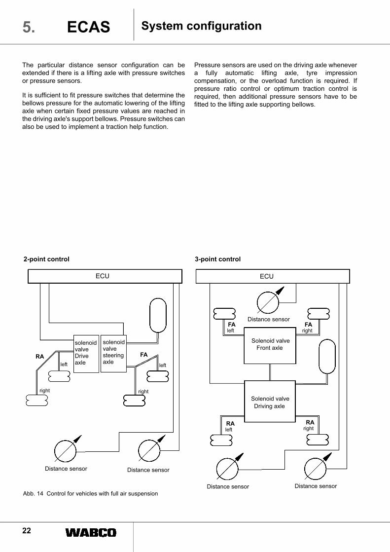
Its PIN assignment corresponds to the illustrated pin
assignment of the ECAS ECU 4x2 A (↑ Fig. 24).
An external characteristic feature of an electronic control
unit is the printed circuit board with the 25-pin terminal
strip rests on an aluminium plate. The housing top
section is made of plastic and is clipped onto the bottom
section.
Abb. 27 ECAS 4x2 Ratio
This group includes the following variants:
- 446 055 301 0 (MAN)
- 446 055 302 0 (MAN)
- 446 055 307 0 (IVECO)
These electronic systems can be diagnosed using the
WABCO diagnostic card 446 300 881 0 (↓ 8. Diagnosis).
6.2.6 ECAS 4x2 (Ratio) KWP 2000
Is an advancement over the generation 4x2 A. The ECU
is still designed for connecting a 25-pin connector. This
ECU is used for controlling 4x2 vehicles with partial or full
air suspension. It is very similar to the ECAS ECU 4x2
Ratio, the main difference being the diagnostic function
in accordance with the "Key Word Protocol 2000" (KWP
2000). Another important difference here is that distance
sensors can be connected without temperature
compensation.
Its PIN assignment corresponds to the illustrated pin
Order Number Design
446 055 040 0 replaced by 446 055 042, on the other hand, is replaced by 446 055 046.
446 055 041 0 replaced by 446 055 047 (MAN) replaced by 446 055 048 (Scania)
446 055 042 0 replaced by 446 055 046
446 055 044 0 is replaced according to system outfit and vehicle manufacture by 446 055 403 (RVI) or 446 055 405 (DAF)
446 055 046 0 35-pin 2-3 DS, PS
446 055 047 0 replaced by 446 055 404 / 409 (MAN)
446 055 048 0
!
1
18
19
35
Fig. 26 PIN assignment of the 35-pin ECU for 6x2 vehicles
1 Terminal 30 (8A fuse)
2 L-line diagnosis
3
4 K-line diagnosis
5 Pressure switch RA 11t signal
Pressure sensor, support bellows right
6 Pressure switch RA 13t signal
Pressure sensor, support bellows left
7 Stop-light switch
8 Distance sensor, rear right
9 Terminal 15 / RCU
10
11 Directional control valve 2/2 FA
12 Lifting axle lowering / TA Load
13 Directional control valve 2/2 RA left
14 separate breather valve for LA
15 Breather valve
16 Coding PIN traction help
17 Traction help switch
18 Traction help / LA position lamp
19 Coding PIN traction help
20 CLOCK line RCU
21 DATA line RCU
22 C3/D3 signal (speedometer)
23 NL I/II-switch (with lamp)
24 Lifting axle switch / Unladen drive switch
25 Distance sensor, rear left
26 Distance sensor, front
27 Distance sensor ground + terminal 31
28
29 Solenoid valve LSV function
30 Lifting axle lifting / TA Relief
31 Directional control valve 2/2 RA right
32 Ground connection - DISTANCE
SENSOR and PRESSURE SENSOR
33 Fault lamp max. 10W
34 Warning lamp, level traction help
35 LA position lamp (sep. Breather valve for
LA)
31
Components 6.ECAS
assignment of the ECAS ECU 4x2 Ratio (↑ Fig. 24).
There are the following minor differences between this
system and the 4x2 Ratio:
– As an option, PIN 5 can be connected to the positive
terminal of a separate battery (was not previously
occupied).
– PIN 22 is not assigned (used to be used for the load-
sensing valve safety function – a typical MAN
function).
– PIN 3 is the flashing code activation lamp for fault
determination and for deleting the fault memory
without using the Diagnostic Controller (used to be
the L-line, but is no longer needed with KWP 2000).
Externally, the electronic control unit is identical to the
ECU for ECAS 4x2 (Ratio).
This group includes the following variants:
- 446 055 303 0 (RVI)
- 446 055 304 0 (RVI)
- 446 055 311 0 (DAF)
- 446 055 312 0 (Leyland)
These electronic control units can be diagnosed using
the WABCO diagnostic card 446 300 880 0 and the PC
diagnostic program 446 301 524 0 (↓ 8. Diagnosis).
ECU 446 055 … 0 when servicing
6.2.7 ECAS 6x2 Ratio
This ECU generation is a revised version of the
electronic control units intended for connecting a 35-pin
connector.
The same vehicles mentioned in the context of ECAS
6x2 A can be controlled with this ECU.
Different manufacturers implement axle load sensing in
different ways, using pressure switches (MAN) or
pressure sensors (RVI, DAF) on the driving axle only.
Lifting or trailing axle control is thus implemented as
pressure equalising control in the same manner as for
ECAS 6x2 A (i. e., the pressure level is identical in all the
supporting bellows while the lifting or trailing axle is
active).
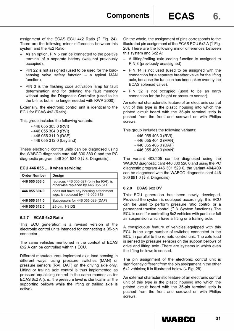
On the whole, the assignment of pins corresponds to the
illustrated pin assignment of the ECAS ECU 6x2 A (↑ Fig.
26). There are the following minor differences between
this system and 6x2 A:
– A lifting/trailing axle coding function is assigned to
PIN 3 (previously unassigned)
– PIN 14 is not used (used to be assigned with the
connection for a separate breather valve for the lifting
axle, because the function has been taken over by the
ECAS solenoid valve).
– PIN 32 is not occupied (used to be an earth
connection for the height or pressure sensor).
An external characteristic feature of an electronic control
unit of this type is the plastic housing into which the
printed circuit board with the 35-pin terminal strip is
pushed from the front and screwed on with Philips
screws.
This group includes the following variants:
- 446 055 403 0 (RVI)
- 446 055 404 0 (MAN)
- 446 055 405 0 (DAF)
- 446 055 409 0 (MAN)
The variant 403/405 can be diagnosed using the
WABCO diagnostic card 446 300 526 0 and using the PC
diagnostic program 446 301 529 0, the variant 404/409
can be diagnosed with the WABCO diagnostic card 446
300 881 0 (↓ 8. Diagnosis).
6.2.8 ECAS 6x2 DV
This ECU generation has been newly developed.
Provided the system is equipped accordingly, this ECU
can be used to perform pressure ratio control or a
permanent traction control (↑ 3. System functions). The
ECU is used for controlling 6x2 vehicles with partial or full
air suspension which have a lifting or a trailing axle.
A conspicuous feature of vehicles equipped with this
ECU is the large number of switches connected to the
ECU in parallel to the remote control unit. The axle load
is sensed by pressure sensors on the support bellows of
drive and lifting axle. There are systems in which even
the lifting bellows is sensed.
The pin assignment of the electronic control unit is
significantly different from the pin assignment in the other
6x2 vehicles; it is illustrated below (↓ Fig. 28).
An external characteristic feature of an electronic control
unit of this type is the plastic housing into which the
printed circuit board with the 35-pin terminal strip is
pushed from the front and screwed on with Philips
screws.
Order Number Design
446 055 303 0 replaces 446 055 027 (only for RVI); is otherwise replaced by 446 055 311
446 055 304 0 does not have any housing attachment lugs, is replaced by 446 055 312
446 055 311 0 Successors for 446 055 029 (DAF)
446 055 312 0 25-pin, 1-3 DS

32
Components6. ECAS
Fig 29 ECAS 6x2 DV
This group includes the following variants:
- 446 055 043 0 (Scania)
- 446 055 049 0 (IVECO)
- 446 055 401 0 (Scania)
- 446 055 402 0 (IVECO)
- 446 055 406 0 (Scania)
- 446 055 407 0 (Nissan Diesel)
- 446 055 408 0 (Mitsubishi)
These electronic control units can be diagnosed using
the WABCO diagnostic card 446 300 623 0 and the PC
diagnostic program 446 301 529 0 (↓ 8. Diagnosis).
When servicing, it may happen that certain ECUs are no
longer available because they have been replaced by an
improved variant.
ECU 446 055 … 0 when servicing
6.2.9 ECAS 4x2/6x2 24V CAN1
This ECU generation is a new development in electronic
control units suitable for use in vehicles equipped with a
CAN bus. This ECAS electronic system uses the bus
system and transmits information to the interconnected
electronic systems of the vehicle.
The information collected in other electronic systems of
the vehicle (e. g. speed, brake light, or bellows pressure/
axle load - only in the case of MAN) are used for
adjustments.
These electronic control units are diagnosed either using
the ECU's own K-line (MAN) or via a central K-line, in
which case the ECAS ECU itself only has a CAN
interface (DaimlerChrysler).
Order Number Design
446 055 043 0 is replaced by 446 055 401
446 055 049 0 is replaced by 446 055 402
446 055 401 0 replaces 446 055 043, is otherwise replaced by 446 055 406
446 055 402 0 35-pin, 2-3 DS, max. 5 PS
446 055 406 0 35-pin, 1-2 DS, max. 3 PS
446 055 407 0
446 055 408 0
1
18
19
35
Fig. 28 PIN assignment of the 35-pin ECU for 6x2 vehicles with pressure ratio control (6x2 DV)
1 Terminal 30 (8A fuse)
2 L-line diagnosis
3 Lifting axle lifting/lowering switch
4 K-line diagnosis
5 Signal, pressure sensor
LA support bellows right
6 Signal, pressure sensor
LA support bellows left
7 Signal, pressure sensor
RA support bellows left
8 Distance sensor, rear right
9 Terminal 15 / RCU
10 DV-/traction switch
11 Directional control valve 2/2 FA
12 Directional control valve 2/2 LA support
bellows left
13 Directional control valve 2/2 RA left
14 Directional control valve 2/2 lifting bellows
15 Breather valve
16 Stop-light switch
17 Traction help switch
18 Traction help lamp
19 NL I/II switch
20 CLOCK line RCU
21 DATA line RCU
22 C3/D3 signal (speedometer)
23 Signal, pressure sensor RA support
bellows right
24 Enable traction help or Signal, pressure
sensor lifting bellows
25 Distance sensor, rear left
26 Distance sensor, front
27 Distance sensor ground + terminal 31
28 Axle load change-over
29 Solenoid valve LSV function
30 Directional control valve 2/2 LA support
bellows right
31 Directional control valve 2/2 RA right
32
33 Fault lamp
34 Warning lamp, level traction help
35 LA position lamp
33
Components 6.ECAS
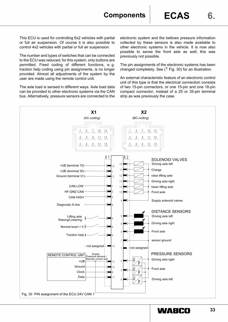
This ECU is used for controlling 6x2 vehicles with partial
or full air suspension. Of course it is also possible to
control 4x2 vehicles with partial or full air suspension.
The number and types of switches that can be connected
to the ECU was reduced; for this system, only buttons are
permitted. Fixed coding of different functions, e. g.
traction help coding using pin assignments, is no longer
provided. Almost all adjustments of the system by the
user are made using the remote control unit.
The axle load is sensed in different ways. Axle load data
can be provided to other electronic systems via the CAN
bus. Alternatively, pressure sensors are connected to the
electronic system and the bellows pressure information
collected by these sensors is also made available to
other electronic systems in the vehicle. It is now also
possible to sense the front axle as well; this was
previously not possible.
The pin assignments of the electronic systems has been
changed completely. See (↑ Fig. 30) for an illustration.
An external characteristic feature of an electronic control
unit of this type is that the electrical connection consists
of two 15-pin connectors, or one 15-pin and one 18-pin
compact connector, instead of a 25 or 35-pin terminal
strip as was previously the case.
1
2
3
1 3
1 5
8
1 1
4
5
1 0
7
1 2
1 0
1 1
1 2
1 3
1 4
1 5
4
5
9
8
7
UP
2
UP
3
UP
6
X 1 X 2
1
2
3
4
5
6
7
8
9
1 0
1 1
1 2
1 3
1 4
1 5
1
2
3
4
5
6
7
8
9
1 0
1 1
1 2
1 3
1 4
1 5
9
6
1 41
Fig. 30 PIN assignment of the ECU 24V CAN 1
SOLENOID VALVES
DISTANCE SENSORS
PRESSURE SENSORS REMOTE CONTROL UNIT
Driving axle left
Charge
raise lifting axle
Driving axle right
lower lifting axle
Front axle
Supply solenoid valves
Driving axle left
Driving axle right
Front axle
sensor ground
- not assigned -
Driving axle left
Driving axle right
Front axle
+UB (terminal 15)
+UB (terminal 30)
Ground (terminal 31)
CAN LOW
HF-GND CAN
CAN HIGH
Diagnostic K-line
Lifting axle Raising/Lowering
Normal level I / II
Traction help
+UB
Ground
Clock
Data
Supply Pressure sensors / Remote control unit
- not assigned -
X2 (BC-coding) (AC-coding)
X1

34
ComponentsECAS6.
The printed circuit board is pushed into the aluminium
housing from the connector side. The cooling ribs on the
rear of the housing are also striking features. The latest
housings are made of plastic and have 15/18-pin
connectors..
Abb. 31 ECAS 4x2 CAN and ECAS 6x2 CAN
This group includes the following variants:
- 446 170 001 0 (DaimlerChrysler)
- 446 170 002 0 (DaimlerChrysler)
- 446 170 003 0 (MAN TGA)
- 446 170 004 0 (DaimlerChrysler)
- 446 170 005 0 (DaimlerChrysler)
- 446 170 006 0 (MAN)
- 446 170 021 0 (DaimlerChrysler)
- 446 170 022 0 (DaimlerChrysler)
- 446 170 023 0 (DaimlerChrysler)
- 446 170 024 0 (DaimlerChrysler)
- 446 170 025 0 (DC ACTROS / ATEGO)
- 446 170 026 0 (DC ACTROS / ATEGO)
- 446 170 051 0 (DaimlerChrysler)
- 446 170 052 0 (DaimlerChrysler)
- 446 170 053 0 (MAN TG-A)
- 446 170 054 0 (DaimlerChrysler)
- 446 170 055 0 (DC ACTROS)
The versions of the electronic control units for
DaimlerChrysler can be diagnosed using the WABCO
diagnostic card 446 300 635 0, while the versions of the
electronic control units for MAN can be diagnosed using
the WABCO diagnostic card 446 300 893 0 and the PC
diagnostic program 446 301 524 0 ↓ 8. Diagnosis).
When servicing, it may happen that certain ECUs are no
longer available because they have been replaced by an
improved variant.
ECU 446 170 … 0 when servicing
If the ECU is replaced, note that a different diagnostic
card may be required for diagnosis.
The 2nd generation of this group, i.e. CAN 2, is now on
the market. This caters for additional vehicle
manufacturers. In detail, this group includes the following
variants:
- 446 170 201 0 (IVECO)
- 446 170 202 0 (IVECO)
- 446 170 206 0 (Scania)
- 446 170 207 0 (MAN TG-A/TG-1(B)
- 446 170 208 0 (MAN TG-A/TG-1(B)
- 446 170 209 0 (MAN TG-A/TG-1(B)
- 446 170 211 0 (IVECO)
- 446 170 212 0 (IVECO)
- 446 170 213 0 (DAF)
- 446 170 214 0 (DAF)
- 446 170 215 0 (Scania)
- 446 170 216 0 (Scania)
Abb. 32 ECAS 4x2 CAN 2
ECU 446 170 … 0 when servicingOrder Number Design
446 170 001 0 is replaced by 446 170 004
446 170 002 0 is replaced by 446 170 005
446 170 003 0 18/15-pin, 1-3 DS
446 170 004 0 is replaced by 446 170 023
446 170 005 0 is replaced by 446 170 024
446 170 006 0
446 170 021 0 is replaced by 446 170 023
446 170 022 0 is replaced by 446 170 024
446 170 023 0 is replaced by 446 170 025
446 170 024 0 is replaced by 446 170 026
446 170 025 0 18/15-pin, 3 DS
446 170 026 0 18/15-pin, 2 DS
446 170 051 0 is replaced by 446 170 052
446 170 052 0 is replaced by 446 170 054
446 170 053 0 18/15-pin, 1-3 DS, max. 3 PS
446 170 054 0 is replaced by 446 170 055
446 170 055 0 18/15-pin, 1-3 DS, max. 3 PS
Order Number Design
446 170 201 0
446 170 202 0
446 170 205 0 is replaced by 446 170 215
446 170 206 0 is replaced by 446 170 216
Order Number Design
!
35
Components 6.ECAS
Diagnosis of these electronic control units is only be
possible using a PC. The reasons for this are the
increased functional range and the completely revised
design of the electronic control unit, including a structure
of parameter sets. For this purpose, the PC program 446
301 524 0 is used. No provision is made for use of a
Diagnostic-Controller card here.
6.2.10 ECAS/ESAC
This generation of ECUs comprises electronic control
units with an integrated ESAC function. Basically, there
are 2 different ECU groups:
- 446 155 … 0 (MAN – 3-stage damping)
- 446 171 … 0 (DaimlerChrysler;
(MAN - continuously
adjustable damping)
In 4x2 vehicles the axle load is also sensed by pressure
sensors on all supporting bellows of the driving axle as
well as on the front axle. The shock absorbers can be set
to three different levels (i. e. soft, medium and hard), or
be continuously adjustable. The damper setting that is
applied depends on the ECU generation used.
The ESAC functions in these electronic control units will
not be dealt with any further at this point since they are
not directly linked to the subject matter of this booklet.
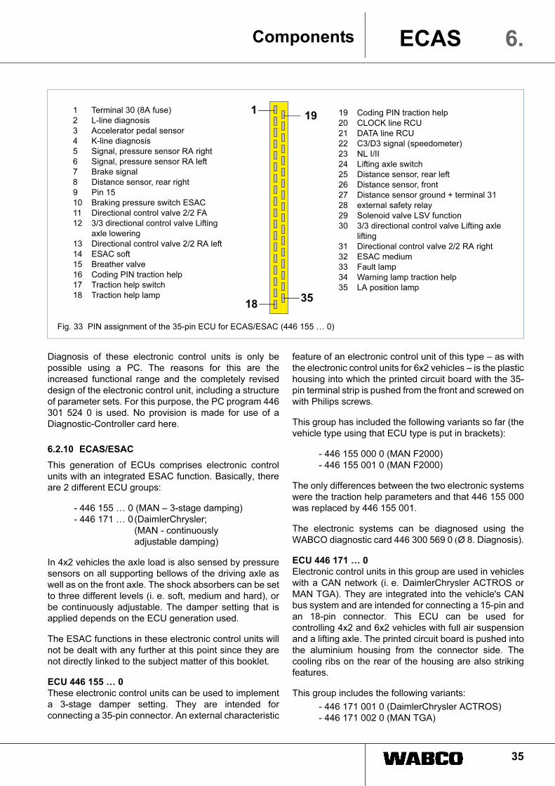
ECU 446 155 … 0
These electronic control units can be used to implement
a 3-stage damper setting. They are intended for
connecting a 35-pin connector. An external characteristic
feature of an electronic control unit of this type – as with
the electronic control units for 6x2 vehicles – is the plastic
housing into which the printed circuit board with the 35-
pin terminal strip is pushed from the front and screwed on
with Philips screws.
This group has included the following variants so far (the
vehicle type using that ECU type is put in brackets):
- 446 155 000 0 (MAN F2000)
- 446 155 001 0 (MAN F2000)
The only differences between the two electronic systems
were the traction help parameters and that 446 155 000
was replaced by 446 155 001.
The electronic systems can be diagnosed using the
WABCO diagnostic card 446 300 569 0 (Ø 8. Diagnosis).
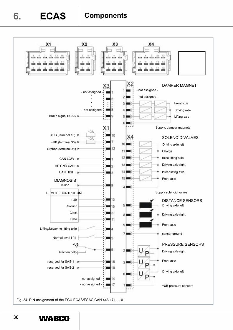
ECU 446 171 … 0
Electronic control units in this group are used in vehicles
with a CAN network (i. e. DaimlerChrysler ACTROS or
MAN TGA). They are integrated into the vehicle's CAN
bus system and are intended for connecting a 15-pin and
an 18-pin connector. This ECU can be used for
controlling 4x2 and 6x2 vehicles with full air suspension
and a lifting axle. The printed circuit board is pushed into
the aluminium housing from the connector side. The
cooling ribs on the rear of the housing are also striking
features.
This group includes the following variants:
- 446 171 001 0 (DaimlerChrysler ACTROS)
- 446 171 002 0 (MAN TGA)
1
18
19
35
Fig. 33 PIN assignment of the 35-pin ECU for ECAS/ESAC (446 155 … 0)
1 Terminal 30 (8A fuse)
2 L-line diagnosis
3 Accelerator pedal sensor
4 K-line diagnosis
5 Signal, pressure sensor RA right
6 Signal, pressure sensor RA left
7 Brake signal
8 Distance sensor, rear right
9 Pin 15
10 Braking pressure switch ESAC
11 Directional control valve 2/2 FA
12 3/3 directional control valve Lifting
axle lowering
13 Directional control valve 2/2 RA left
14 ESAC soft
15 Breather valve
16 Coding PIN traction help
17 Traction help switch
18 Traction help lamp
19 Coding PIN traction help
20 CLOCK line RCU
21 DATA line RCU
22 C3/D3 signal (speedometer)
23 NL I/II
24 Lifting axle switch
25 Distance sensor, rear left
26 Distance sensor, front
27 Distance sensor ground + terminal 31
28 external safety relay
29 Solenoid valve LSV function
30 3/3 directional control valve Lifting axle
lifting
31 Directional control valve 2/2 RA right
32 ESAC medium
33 Fault lamp
34 Warning lamp traction help
35 LA position lamp
36
Components6. ECAS
Fig. 34 PIN assignment of the ECU ECAS/ESAC CAN 446 171 … 0
SOLENOID VALVES
DISTANCE SENSORS
PRESSURE SENSORS
REMOTE CONTROL UNIT
Driving axle left
Charge
raise lifting axle
Driving axle right
Front axle
Supply, damper magnets
Driving axle left
Driving axle right
Front axle
sensor ground
- not assigned -
Driving axle left
Driving axle right
Front axle
+UB (terminal 15)
+UB (terminal 30)
Ground (terminal 31)
CAN LOW
HF-GND CAN
CAN HIGH
DIAGNOSIS
reserved for SAS-1
Lifting/Lowering lifting axle
Normal level I / II
Traction help
+UB
Ground
Clock
Data
- not assigned -+UB pressure sensors
Supply solenoid valves
lower lifting axle
Lifting axle
Driving axle
Front axle
- not assigned -
DAMPER MAGNET
- not assigned -
reserved for SAS-2
+UB
K-line
Brake signal ECAS
- not assigned -....
- not assigned -
37
Components 6.ECAS
- 446 171 003 0 (DaimlerChrysler ACTROS)
- 446 171 004 0 (DaimlerChrysler AXOR)
The electronic system 446 171 002 is diagnosed using
the WABCO diagnostic card 446 300 893 0 and the PC
diagnostic program 446 301 524 0. The other ECUs can
be diagnosed using the WABCO diagnostic card 446 300
635 0 and the PC diagnosis.
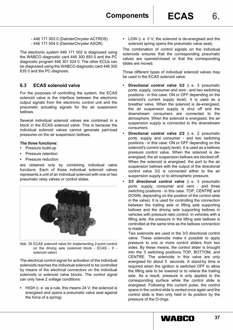
6.3 ECAS solenoid valve
For the purposes of controlling the system, the ECAS
solenoid valve is the interface between the electronic
output signals from the electronic control unit and the
pneumatic actuating signals for the air suspension
bellows.
Several individual solenoid valves are combined in a
block in the ECAS solenoid valve. This is because the
individual solenoid valves cannot generate part-load
pressures on the air suspension bellows.
The three functions:
• Pressure build-up
• Pressure retention
• Pressure reduction
are obtained only by combining individual valve
functions. Each of these individual solenoid valves
represents a unit of an individual solenoid with one or two
pneumatic relay valves or control slides.
Abb. 35 ECAS solenoid valve for implementing 2-point control
on the driving axle (solenoid block - ECAS - II -
solenoid valve)
The electrical control signal for activation of the individual
solenoids reaches the individual solenoid to be controlled
by means of the electrical connectors on the individual
solenoids or solenoid valve blocks. The control signal
can only have 2 voltage conditions:
• HIGH (i. e. as a rule, this means 24 V; the solenoid is
energised and opens a pneumatic valve seat against
the force of a spring).
• LOW (i. e. 0 V; the solenoid is de-energised and the
solenoid spring opens the pneumatic valve seat).
The combination of control signals on the individual
solenoids ensures that the corresponding pneumatic
valves are opened/closed or that the corresponding
slides are moved.
Three different types of individual solenoid valves may
be used in the ECAS solenoid valve:
• Directional control valve 3/2 (i. e. 3 pneumatic
ports: supply, consumer and vent - and two switching
positions - in this case: ON or OFF depending on the
solenoid's current supply level). It is used as a
breather valve. When the solenoid is de-energised,
the air suspension supply is shut off and the
downstream consumers are connected to the
atmosphere. When the solenoid is energised, the air
suspension supply is connected to the downstream
consumers.
• Directional control valve 2/2 (i. e. 2 pneumatic
ports: supply and consumer - and two switching
positions - in this case: ON or OFF depending on the
solenoid's current supply level). It is used as a bellows
pressure control valve. When the solenoid is de-
energised, the air suspension bellows are blocked off.
When the solenoid is energised, the port to the air
suspension bellows with the output of the directional
control valve 3/2 is connected either to the air
suspension supply or to atmospheric pressure.
• 3/3 directional control valve (i. e. 3 pneumatic
ports: supply, consumer and vent - and three
switching positions - in this case: TOP, CENTRE and
DOWN, depending on the position of the control slide
in the valve). It is used for controlling the connection
between the trailing axle or lifting axle supporting
bellows and the driving axle supporting bellows in
vehicles with pressure ratio control. In vehicles with a
lifting axle, the pressure in the lifting axle bellows is
controlled at the same time as the bellows connection
is made.
Two solenoids are used in the 3/3 directional control
valve. These solenoids make it possible to apply
pressure to one or more control sliders from two
sides. By these means, the control slider is brought
into the 3 switching positions TOP, BOTTOM, and
CENTRE. The solenoids in this valve are only
energised for about 5 seconds. A stand-by time is
required when the ignition is switched OFF to allow
the lifting axle to be lowered or to relieve the trailing
axle. As a result, pressure is only applied to the
corresponding surface while the control slide is
energised. Following this current pulse, the control
space in the control slide is vented once again and the
control slide is then only held in its position by the
pressure of the O-rings.

38
ComponentsECAS6.
Depending on the solenoid control of air valves,
there are two types of valves:
6.3.1 Spring-returned valve
The pneumatic control system is an indirect control
system (↓ Fig. 36) because it comprises a pilot control
section and a main control section. The solenoid
controlled by the ECU opens a relatively small valve
seat, which causes pressure to build up (pilot control).
• In the case of ECAS solenoid valves with a control
piston, this pressure opens a plate valve with a large
flow cross-section, and the air then flows through this
cross-section.
• In the case of ECAS solenoid valves with a control
slide, this pressure moves the slide piston into the
required position. This causes the pneumatic
connections in the ECAS solenoid valve to connected
or disconnected from one another.
Abb. 36 Cross-section view of an ECAS solenoid valve with
spring-returned seat valves for the driving axle
(solenoid block ECAS-II solenoid valve)
A directional control valve 3/2 designed as a seat valve
functions in according to the following principle:
1. The permanently energised solenoid 6.1 opens a
valve seat 1 and allows the supply pressure from
channel 4 to the top side of control piston 3 (pilot
control) via channel 2.
2. The piston (3) now opens the valve seat (6) against
the force of a return spring.
This allows air to flow into the channel (5) and
downstream consumers (main control).
When the solenoid is no longer energised:
3. Valve seat (1) is closed, and the top of the control
piston (3) is exhausted.
4. The valve spring closes valve seat (6) and, with the
help of the piston return spring, returns the control
piston (3) to its original position.
5. Channel 5 and any downstream consumers are
exhausted by means of the hollow control piston (3).
Operation of the directional control valves 2/2 follows the
same principle.
Abb. 37 Cross-section view of an ECAS solenoid valve with
spring-returned sliding valves for the main axle or the
main axle section (solenoid block)
In more recent ECAS solenoid valves, the seat valves
are progressively being replaced by sliding valves. The
spring-returned sliding valve (↑ Fig. 37) works in a similar
fashion. The essential difference is that the seat valves
have been replaced by slides; these, however, are also
controlled by a return spring.
6.3.2 Pulse-controlled slide valve
The pulse-controlled slide valve is a 3/3 directional
control valve within the ECAS solenoid valve. It is mainly
used to control the lifting axle bellows together with the
supporting bellows of the lifting axle. Automatic lifting
axle operation can be implemented using pulse-
controlled valves. Usually the group of solenoid valve for
controlling the lifting bellows are flanged onto the group
of solenoid valves for controlling the main axle.
Directional control valve3/2 2/2 2/2
Directional control valve3/2 2/2 2/2

39
Components 6.ECAS
Abb. 38 Cross-section view of an ECAS solenoid valve with
pulse-controlled slide valves for the lifting axle portion
in the "hold pressure" position
The 3/3 directional control valves (↑ Fig. 38) operate as
follows:
1. In annular chamber (1), the supply pressure acts on
control solenoid (62.3 'raise' lifting axle) and (62.1
'lower' lifting axle) via channel (2).
2. For raising, control solenoid (62.3) receives a current
pulse - hence pulse-controlled - and opens its valve
seat.
3. Air is let into the annular chamber (3) at control piston
(4) via the system of ducts.
4. This forces the control piston upwards and the
annular chamber (1) is connected with the annular
chamber (6) at whose outlet the lifting bellows are
connected.
5. This causes the lifting bellows to be charged.
6. At the same time, pressure acts on the top of the two
control piston (5) as the pressure in chambers (11) is
increased, and the control pistons are forced
downwards.
7. The annular chambers (8) connected to the
supporting bellows of the lifting axle are connected to
channel (12) and exhausted via vent (32).
8. These processes cause the lifting axle to be raised.
When there is no longer any current pulse on the
solenoid, chambers (3) and (11) are exhausted via the
solenoid vent.
The slide positions in the ECAS solenoid valve remain
as they are until a subsequent control acts on them.
1. To lower the lifting axle, the solenoid (62.1) receives
a current pulse and opens its valve seat.
2. Air is let into the annular chamber (10) at control
piston (4) via a system of ducts.
3. This pushes the piston downwards and the annular
chamber (6) whose outlet is connected to the lifting
bellows is connected to the channel (12) .
4. The lifting axle bellows are therefore vented.
5. At the same time, the annular chambers (7), where
the supporting bellows pressure is generated, are
connected to the annular chambers (8) to which the
support bellows of the lifting axle are connected.
6. The same pressure is therefore applied to the
supporting bellows of the main axle and the lifting
axle.
7. These processes cause the lifting axle to be lowered.
8. When there is no longer any current pulse on the
solenoid, chambers (9) and (10) are exhausted by
means of the solenoid vent.
The valve position (↑ Fig. 38) represents a special case
and causes the pressure in all bellows to be held. This
will occur, for instance, when the pressure in the
supporting bellows for the main axle and the lifting axle
vary while traction help is active. This means the
pressure in the supporting bellows of the main axle is at
its maximum and the pressure in the supporting bellows
of the lifting axle is lower. This condition is achieved by
control solenoids (62.1) and (62.3) being continuously
switched on simultaneously.
6.3.3 Distinguishing ECAS solenoid valves
Essentially, there are three groups of ECAS solenoid
valves, distinguished according to their application:
• Front axle valve (FA valve)
• Rear axle valve (RA valve)
• Rear axle/lifting axle valve (RA/LA valve)
The outgoing bellows lines should be symmetrical, i. e.
they should have identical line lengths and the same line
diameter. Take care to assign the electrical and
pneumatic connections correctly in accordance with the
numbering system.
Front axle valve (FA valve)
The FA valve is located near the front axle and controls
the supporting bellows for the front axle. The FA valve
usually has only one directional control valve 2/2 for the
front axle (steering axle), i.e. it can only perform the
opening/blocking function.
62.3 62.1
11 11 10
12 12
99 3
77
88 6
1
45
2

40
Components6. ECAS
The process of ventilation (i.e., increasing and
decreasing pressure by venting and exhausting) is
controlled by the directional control valve 3/2 of the rear
axle valve.
Abb. 39 FA valve with DIN bayonet 472 900 058 0
Rear axle valve (RA valve)
The RA valve is the core valve of an ECAS system
without automatic lifting axle operation and is located in
the rear axle section. It controls the driving axle support
bellows in vehicles with partial or full air suspension but
without a lifting or trailing axle. Ventilation of the FA valve
(i.e., increasing and decreasing pressure by venting and
exhausting) in vehicles with full air suspension is
implemented by means of a pneumatic output, this
output being closed in vehicles with partial air
suspension.
Depending on the type of ECAS system used, the RA
valve for controlling the supporting bellows is equipped
with the following respectively:
• One directional control valve 2/2 if the axle has a 1-
point control
• Two directional control valves 2/2 if the axle has a 2-
point control
Abb. 40 RA valve with DIN bayonet 472 900 055 0
Rear axle/lifting axle valve (RA/LA valve)
The RA/LA valve is the core valve of a system with
automatic lifting axle operation and is located in the rear
axle section. It controls the support bellows of the driving
axle in vehicles with partial and full air suspension, as
well as the lifting bellows and the support bellows of the
lifting axle. In systems with pressure ratio control /
optimum traction control it is even possible to operate a
vehicle with full air suspension (i. e. the supporting
bellows on the front axle as well) using one ECAS
solenoid valve.
Abb. 41 RA/LA valve with DIN bayonet 472 905 114 0
The valve consists of a rear axle block and a lifting axle
block. Its functions is similar to that of the rear axle valve.
An additional pneumatic output in the rear axle block
enables ventilation of the FA valve. The valves fitted in
the lifting axle block depend on whether it is an ECAS
system with pressure equalising control or with pressure
ratio control/optimum traction control.
There are three 3/3 directional control valves in the lifting
axle valve block for ECAS systems with pressure
equalising control. These are actuated by two valve
solenoids and are responsible for controlling the lifting
bellows and the supporting bellows of the lifting axle.
The lifting axle valve block for ECAS systems with
pressure ratio control/optimum traction control contains
up to three directional control valves 2/2 which are
responsible for controlling the lifting bellows and the
supporting bellows of the lifting axle.
Clear assignments can only be made by referring to
a circuit diagram (↓ 7. Brief system description ).
Whilst the assignment of the electrical connections is not
standardised, the following guideline applies to the
assignment of pneumatic ports for ECAS in the vehicle:
Port 1
Only in the case of RA/LA valves: Supply pressure from
reservoir for downstream consumers.
!

41
Components 6.ECAS
Port 11
Only in the case of FA valves and RA valves: Supply
pressure from reservoir for downstream consumers.
Port 12
Only in the case of FA valves and RA valves: Actuating
pressure from reservoir to actuate the control element in
the ECAS solenoid valve.
Port 13
Not relevant for operation.
Port 14
Only in the case of FA valves: Supply port from RA valve.
Port 21
• In the case of dedicated RA valves: Output for Port 14
of FA valve.
• In the case of RA/LA valves: Output for (left-hand)
supporting bellows of the axle(s) which is (are) on the
ground (pressure equalising control only).
Port 22
Output for (right-hand) supporting bellows of the axle(s)
which is (are) on the ground.
Port 23
• In the case of dedicated FA or RA valves: Output for
(left-hand) supporting bellows of the axle(s) which is
(are) on the ground.
• In the case of RA/LA valves: Output to the (left-hand)
supporting bellows of the lifting axle for fully automatic
lifting axle operation.
Port 24
Output to (right-hand) support bellows of the lifting axle
in the case of fully automatic lifting axle operation.
Port 25
Output to lifting bellows on the lifting axle for fully
automatic lifting axle operation.
Port 26
• In the case of RA/LA valves: Output to port 14 of the
FA valve (pressure equalising control only).
• On buses also output to supporting bellows on the
front axle for the 'kneeling' function.
Port 27
• Not relevant for operation.
• On buses also output to supporting bellows on the
front axle for the 'kneeling' function.
Port 3
Only on RA valves: Exhausting for downstream
consumers.
Port 31
Only in the case of RA/LA valves: Exhausting for
downstream consumers in rear axle block.
Port 32
Only in the case of RA/LA valves: Exhausting for
downstream consumers in lifting axle block.
6.3.4 Interchangeability of the ECAS solenoid
valves
It is possible to distinguish one generation of ECAS
solenoid valve from another on the basis of the valve
solenoids' design. There are more than 60 different types
of ECAS solenoid valve. The product group 472 900 … 0
comprises the FA, RA valves and RA/LA valves for
systems with basic control and pressure ratio control/
traction control. The product group 472 905 … 0 includes
the RA/LA valves for pressure equalising control.
The new generation of ECAS solenoid valve (ECAS III)
was introduced in the year 2000. This solenoid valve
generation is grouped in the product group 472 880 … 0
and is meant to replace the ECAS solenoid valves of the
product group 472 900 … 0 in future.
Abb. 41 RA valve with DIN bayonet 472 880 030 0
As a general rule, it is possible to subdivide the various
versions into groups with the same function. The main
differences between devices in the same group concern
the electrical and pneumatic interface.
Devices with specially shaped connection threads -
these being required by special pipe connection systems
- do not represent a particular problem should the
corresponding pipe couplings not be on hand. If need be
(i.e. repair is required), pipe couplings according to DIN
may still be used.
However, problems of a different magnitude arise if the
electrical connections to the valve solenoids are
configured differently. For example, solenoid control can
be implemented as an individual control with a thread or
as a valve block control with a connection bayonet. The
connection bayonet may vary from one type to another
(KOSTAL or DIN bayonet). There can be different

42
ComponentsECAS6.
contact arrangements even within the same bayonet
type, and this may rule out interchangeability. In this
case, the only thing to do is to replace the corresponding
cable at the same time.
The following tables present a brief list of the most
important ECAS solenoid valves with equivalent
functions and provide some information about
interchangeability.
The following applies to the designation of the electrical
connection (E-conn.) as a DIN bayonet:
Connector DIN 72 585-A1-4.1-Sn/K1 (example)
A1= = fixed connector (A) with coding strip assignment
1 in the connector plug (4 different arrangements
are possible).
4.1 = DIN coding of the contact assignment (here: 4
contacts assigned according to variant 1).
Sn = tin-plated contacts.
K1 = Duty class (K2 can be subjected to higher loads
than K1).
The following applies to the pneumatic connections (P-
conn.):
JED-152 = Threaded holes for metric connection thread
according to DIN.
JED-388 = Threaded holes for VOSS plug-in connection
system (can be used for pipe unions according to DIN).
The following table first displays the symbol diagram for
the various groups, followed by a brief description. Some
variants can only be distinguished by the presence/
absence of a silencer (GD).
This and the following groups deal with solenoid valves
which are used for ECAS basic control on the rear (or
driven) axle.
The first group listed in the table consists of RA valves
for 1-point control (1 distance sensor). These valves
have a throttle (diameter 0.6 mm) between the
pneumatic outputs to the left and right side of the
bellows.
Table 1: Solenoid valve
Symbol diagram Order Number E-connection P-connection Comment
472 900 030 0 2 individual solenoids M27x1
VOSS connection M22x1.5
Linchpins of the individual solenoid connections turned at 90° towards one another; with silencer
472 900 032 0 2 individual solenoids M27x1
M 22x1.5 Linchpins of the individual solenoid connections turned at 90° towards one another; without silencer
472 900 033 0 2 individual solenoids M27x1
M 22x1.5 (JED-388)connections with access from top
Linchpins of the individual solenoid connections turned at 90° towards one another; with silencer
472 900 034 0 2 individual solenoids M27x1
M 22x1.5(JED-388)
Linchpins of the individual solenoid connections pointing in the same direction; without silencer
472 900 055 0 2 solenoids 1x bayonet DIN 72585-A1-4.2-Sn/K1
M 22x1.5(JED-388)
472 900 061 0 2 solenoids 1x bayonet DIN 72585-A1-3.1-Sn/K1
M 22x1.5(JED-388)
Special solenoid seal for SCANIA; with silencer(6.3 not assigned)
472 900 065 0 2 solenoids 1x bayonet DIN 72585-A1-4.2-Sn/K1
M 22x1.5(JED-152)
IVECO; with silencer
472 880 030 0 2 solenoids 1x bayonet DIN 72585-A1-4.2-Sn/K1
M 22x1.5(JED-388)
ECAS IIIwith silencer; replaces 472 900 055 0
472 880 031 0 2 solenoids 1x bayonet DIN 72585-A1-3.2-Sn/K2
M 22x1.5(JED-388)
ECAS III special solenoid seal for SCANIA; with silencer replaces 472 900 061 0 (6.3 not assigned)
3
112223
21
2412
42 41
3
112223
21
6.3 6.16.4 6.2

43
Components 6.ECAS
RA valves for 2-point control (2 distance sensors)These valves enable the pneumatic outputs to the air suspension bellows to be controlled separately.Variants:
Symbol diagram Order Number E-connection P-connection Comment
472 900 000 0 3 individual solenoids M27x1
VOSS connection M22x1.5
Replaced by variant 001; with silencer
472 900 001 0 3 individual solenoids M27x1
VOSS connection M22x1.5
Linchpins of the individual solenoid connections left, front, and right; replacement for variant 000; with silencer
472 900 002 0 3 individual solenoids M27x1
M 22x1.5(DIN thread)
Individual solenoid connections as in variant 001; with silencer
472 900 006 0 3 individual solenoids M27x1
M 22x1.5(DIN thread)
Linchpins of the individual solenoid connections 2x front and right; replaced by variant 012; w/o silencer
472 900 008 0 3 individual solenoids M27x1
M 22x1.5 (JED-388)
Individual solenoid connections as in variant 001; P-connections with access from top; with silencer
472 900 009 0 3 individual solenoids M27x1
M 22x1.5(JED-388)
Linchpins of the solenoid connections 2x rear and right; without silencer
472 900 012 0 3 individual solenoids M27x1
M 22x1.5(DIN thread)
Individual solenoid connections as in variant 006; replacement for variant 006; w/o silencer
472 900 014 0 3 individual solenoids M27x1
M 22x1.5(JED-388)
Individual solenoid connections as in variant 001; P-connections with access from top; without silencer
472 900 053 0 1x bayonet DIN 72585-A1-4.1-Sn/K1
M 22x1.5(JED-388)
with silencer
472 900 060 0 1x bayonet DIN 72585-A1-4.1-Sn/K2
M 22x1.5(JED-388)
Port 21 open; with silencer
472 900 062 0 1x bayonet DIN 72585-A1-4.1-Sn/K1
M 22x1.5(JED-388)
special solenoid seal for SCANIA; without silencer
472 900 063 0 1x bayonet DIN 72585-A1-4.1-Sn/K1
M 22x1.5(JED-152)
with silencer
472 900 073 0 1x bayonet DIN 72585-A1-4.1-Sn/K1
M 22x1.5(JED-388)
12V supply voltage: with silencer
472 880 000 0 1x bayonet DIN 72585-A1-4.1-Sn/K2
M 22x1.5(JED-388)
ECAS IIIPort 21 open; with silencer supersedes 472 880 060 0
472 880 001 0 1x bayonet DIN 72585-A1-4.1-Sn/K2
M 22x1.5(JED-388)
ECAS IIIwith silencer; supersedes 472 880 053 0
472 880 002 0 1x bayonet DIN 72585-A1-4.1-Sn/K2
M 22x1.5(JED-388)
ECAS IIIspecial solenoid seal for SCANIA; with silencer;
472 880 070 0 1x bayonet DIN 72585-A1-4.1-Sn/K2
M 22x1.5(JED-388)
ECAS III12V voltage supply; with silencer; supersedes 472 880 073 0
3
112223
21
2412
42 4143
3
112223
21
6.46.2 6.16.3

44
Components6. ECAS
Solenoid valves for basic ECAS control on the front axle.Group 1: FA valves for 1-point control (1 distance sensor)These valves have a throttle (diameter 0.6 mm) between the pneumatic outputs to the left and right side of the bellows. These valves are ventilated (vented and exhausted) via the RA valve connected upstream; this means it is necessary to connect a separate supply line for the pilot control, port 12 (as of ECAS III, port 11).Variants:
Symbol diagram Order Number E-connection P-connection Comment
472 900 020 0 1 individual solenoid M27x1
VOSS connection 3x M22x1.51x M16x1.5
additional port 13 next to port 14 (closed)
472 900 021 0 1 individual solenoid M27x1
VOSS connection 3x M22x1.51x M16x1.5
472 900 022 0 1 individual solenoid M27x1
3x M22x1.51x M16x1.5(DIN thread)
472 900 054 0 1x bayonet DIN 72585-A1-3.6-Sn/K1
3x M22x1.51x M16x1.5(JED-388)
472 900 064 0 1x bayonet DIN 72585-A1-3.6-Sn/K1
3x M22x1.51x M16x1.5(JED-152)
472 900 074 0 1x bayonet DIN 72585-A1-3.6-Sn/K1
3x M22x1.51x M16x1.5(JED-388)
Solenoid turned by 90° when compared to 054
472 900 058 0 1x bayonet DIN 72585-A1-2.1-Sn/K2
3x M22x1.51x M16x1.5(JED-388)
Special model: if required, to be replaced by 472 880 021 0, in which case port 25 can be picked off from port 22 (T-piece); note the difference in thread size!
472 880 020 0 1x bayonet DIN 72585-A1-3.6-Sn/K2
M 22x1.5(JED-388)
ECAS IIIphases out 472 900 054 0
472 880 021 0 1x bayonet DIN 72585-A1-2.1-Sn/K2
M 22x1.5(JED-388)
ECAS IIIphases out 472 900 058 0(6.4 not assigned)
472 880 024 0 1x bayonet DIN 72585-A1-3.6-Sn/K2
M 22x1.5(JED-388)
ECAS III
12
2223
1442
12
22 23
146.2
25
6.1
21
22 23 11
6.26.1 6.4

45
Components ECAS
Symbol diagramSolenoid valves for basic ECAS control on the front axle.Group 2: FA valves used in buses.Apart from the function as a front axle valve, this valve group has an additional directional control valve 2/2 for the kneeling function.
Variants:
Order Number E-connection P-connection Comment
472 900 066 0 1x bayonet DIN 72585-A1-3.6-Sn/K1
1x bayonet DIN 72585-A1-4.1-Sn/K1
3x M22x1.5
1x M16x1.5
(JED-388)
Replaced by 472 880 061 0
472 900 076 0 1x bayonet DIN 72585-A1-3.2-Sn/K1
1x bayonet DIN 72585-A1-4.1-Sn/K1
3x M22x1.5
1x M16x1.5
(JED-388)
12V supply voltage; replaced by 472 880 071 0
472 880 061 0 1x bayonet DIN 72585-A1-3.6-Sn/K2
1x bayonet DIN 72585-A1-4.2-Sn/K2
4x M22x1.5
(JED-388)
ECAS III
supersedes 472 900 066 0; note changed
pneumatic ports; with silencer
472 880 071 0 1x bayonet DIN 72585-A1-3.6-Sn/K2
1x bayonet DIN 72585-A1-4.2-Sn/K2
4x M22x1.5
(JED-388)
ECAS III
12V supply voltage;
supersedes 472 900 066 0; note the
modified pneumatic ports
Symbol diagram FA valve for use in buses. As well as the directional control valve 2/2 for kneeling, these valves also have an independently functioning breather valve.
Order Number E-connection P-connection Comment
472 880 062 0 1x bayonet DIN 72585-A1-3.6-Sn/K2
1x bayonet DIN 72585-A1-4.1-Sn/K2
4x M22x1.5
(JED-388)
ECAS III
SCANIA design; venting function integrated in
the valve; with silencer
472 880 064 0 1x bayonet DIN 72585-A1-3.6-Sn/K2
1x bayonet DIN 72585-A1-4.1-Sn/K2
4x M22x1.5
(JED-388)
ECAS III
Ventilation function (venting and exhausting)
integrated in the valve; with silencer
12
26 27
14
61.461.1 61.362.162.2
62.461.2
1123 22
3
61.461.161.3 62.1 62.262.4
61.2
21
6.

46
ComponentsECAS6.
Solenoid valves used for the traction control / pressure equalising control in complete vehicles or for multi-axle combinations.
Symbol diagramFA/RA valves for 1-point control / 2-point control (3 distance sensors).These valves have a throttle (diameter 0.6 mm) between the pneumatic outputs to the left and right side of the bellows. They are used in 4x2 vehicles. The advantage is that a single valve can be used to coordinate the bellows control for a vehicle with full air suspension.
Variants:
Order Number E-connection P-connection Comment
472 900 052 0 4 individual solenoids M27x1 5x M22x1.5
(JED-388)
for information only, no longer available
472 900 057 0 1x bayonet DIN 72585-A1-3.6-Sn/K1
1x bayonet DIN 72585-A1-4.1-Sn/K1
5x M22x1.5
(JED-388)
replaced by 472 880 050 0; with silencer
472 900 067 0 1x bayonet DIN 72585-A1-3.6-Sn/K1
1x bayonet DIN 72585-A1-4.1-Sn/K1
5x 1/2-14 NPTF
DRYSEAL
replaced by 472 880 051 0; with silencer
472 880 050 0 1x bayonet DIN 72585-A1-3.6-Sn/K2
1x bayonet DIN 72585-A1-4.1-Sn/K2
5x M22x1.5
(JED-388)
ECAS IIIsupersedes 472 900 057 0; with silencer
472 880 051 0 1x bayonet DIN 72585-A1-3.6-Sn/K2
1x bayonet DIN 72585-A1-4.1-Sn/K2
5x 1/2-14 NPTF
DRYSEAL
ECAS IIIsupersedes 472 900 067 0; with silencer
472 880 052 0 1x bayonet DIN 72585-A1-3.6-Sn/K2
1x bayonet DIN 72585-A1-4.1-Sn/K2
5x 1/2-14 NPTF
DRYSEAL
ECAS IIISCANIA design; RA + FA/LA; with silencer
Symbol diagram RA/LA (or RA/TA) valve for 1-point control (1 distance). There is one output on the lifting axle block for the lifting bellows and one output for the support bellows of the lifting axle.
Order Number E-connection P-connection Comment
472 900 113 0 2x bayonet DIN 72585-A1-4.1-Sn/K1 5x M22x1.5
(JED-388)
RA/TA valve (rear axle / trailing axle valve)
1123 22
3
61.461.161.362.162.2 62.4 61.2
212627
1123 22
3
61.461.162.162.262.4 61.2
212223

47
Symbol diagramRA/LA (or RA/TA) valve for 2-point control (2 distance sensors).There are two pneumatic outputs on the valve block for the supporting bellows of the lifting/trailing axle.
Variants:
Order Number E-connection P-connection Comment
472 900 102 0 5 individual solenoids M27x1 VOSS connection
5x M22x1.5
Replaced by 472 900 105 0
472 900 103 0 5 individual solenoids M27x1 5x M22x1.5
(DIN thread)
electrical connections 41 to 43 (also refer to
page 43); with silencer
472 900 105 0 5 individual solenoids M27x1 5x M22x1.5
(JED-388)
Replacement for 472 900 102 0; electrical connections 41 to 43; P-connections with access from top; with silencer
472 900 110 0 1x bayonet DIN 72585-A1-4.1-Sn/K11x bayonet DIN 72585-A1-4.2-Sn/K1
5x M22x1.5(JED-388)
RA/TA valve;
Replacement for 472 900 105 0; with silencer
472 900 112 0 1x bayonet DIN 72585-A1-4.1-Sn/K11x bayonet DIN 72585-A1-3.1-Sn/K1
5x M22x1.5(JED-388)
RA/LA valve; without silencer
changed connector coding on the
electrical connection 62.3
472 880 100 0 1x bayonet DIN 72585-A2-4.1-Sn/K21x bayonet DIN 72585-A1-4.2-Sn/K2
5x M22x1.5(JED-388)
ECAS III
RA/TA valve; supersedes 472 900 110 0; but
changed connector coding on the
electrical connections; with silencer
472 880 101 0 1x bayonet DIN 72585-A1-4.1-Sn/K11x bayonet DIN 72585-A1-3.1-Sn/K1
5x M22x1.5(JED-388)
ECAS III
RA/LA valve; supersedes 472 900 112 0;
without silencer
Symbol diagramRA/LA valves for 2-point control(2 distance sensors).There is one output on the lifting axle block for the lifting bellows and two outputs for the supporting bellows of the lifting axle.
Variants:
Order Number E-connection P-connection Comment
472 900 101 0 6 individual solenoids M27x1 VOSS connection 6x M22x1.5
Replaced by 472 900 111 0
472 900 104 0 6 individual solenoids M27x1 6x M22x1.5(JED-388)
electrical connections 41 to 43 (also refer to page 43); P-connection with access from top; with silencer
472 900 111 0 1x bayonet DIN 72585-A1-4.1-Sn/K11x bayonet DIN 72585-A1-4.2-Sn/K1
6x M22x1.5(JED-152)
Replacement for 472 900 101 0
1123 22
3
61.461.161.362.1 62.262.4 61.2
212627
62.3
1123 22
3
61.461.161.362.1 62.2 62.4 61.2
2126 27
62.3
25
Components ECAS 6.
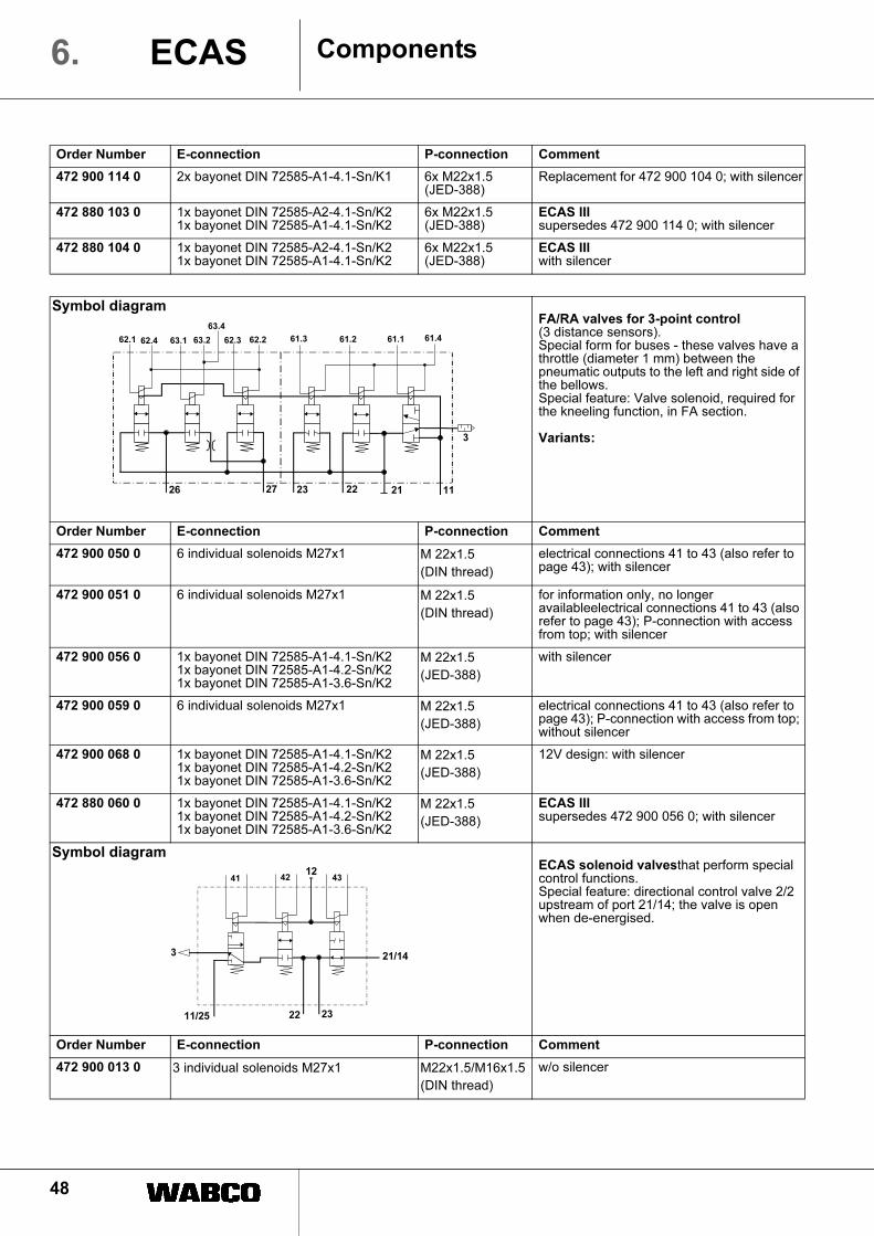
48
ComponentsECAS6.
Order Number E-connection P-connection Comment
472 900 114 0 2x bayonet DIN 72585-A1-4.1-Sn/K1 6x M22x1.5(JED-388)
Replacement for 472 900 104 0; with silencer
472 880 103 0 1x bayonet DIN 72585-A2-4.1-Sn/K21x bayonet DIN 72585-A1-4.1-Sn/K2
6x M22x1.5(JED-388)
ECAS IIIsupersedes 472 900 114 0; with silencer
472 880 104 0 1x bayonet DIN 72585-A2-4.1-Sn/K21x bayonet DIN 72585-A1-4.1-Sn/K2
6x M22x1.5(JED-388)
ECAS IIIwith silencer
Symbol diagramFA/RA valves for 3-point control (3 distance sensors).Special form for buses - these valves have a throttle (diameter 1 mm) between the pneumatic outputs to the left and right side of the bellows.Special feature: Valve solenoid, required for the kneeling function, in FA section.
Variants:
Order Number E-connection P-connection Comment
472 900 050 0 6 individual solenoids M27x1 M 22x1.5
(DIN thread)
electrical connections 41 to 43 (also refer to page 43); with silencer
472 900 051 0 6 individual solenoids M27x1 M 22x1.5
(DIN thread)
for information only, no longer availableelectrical connections 41 to 43 (also refer to page 43); P-connection with access from top; with silencer
472 900 056 0 1x bayonet DIN 72585-A1-4.1-Sn/K21x bayonet DIN 72585-A1-4.2-Sn/K21x bayonet DIN 72585-A1-3.6-Sn/K2
M 22x1.5
(JED-388)
with silencer
472 900 059 0 6 individual solenoids M27x1 M 22x1.5
(JED-388)
electrical connections 41 to 43 (also refer to page 43); P-connection with access from top; without silencer
472 900 068 0 1x bayonet DIN 72585-A1-4.1-Sn/K21x bayonet DIN 72585-A1-4.2-Sn/K21x bayonet DIN 72585-A1-3.6-Sn/K2
M 22x1.5
(JED-388)
12V design: with silencer
472 880 060 0 1x bayonet DIN 72585-A1-4.1-Sn/K21x bayonet DIN 72585-A1-4.2-Sn/K21x bayonet DIN 72585-A1-3.6-Sn/K2
M 22x1.5
(JED-388)
ECAS IIIsupersedes 472 900 056 0; with silencer
Symbol diagramECAS solenoid valvesthat perform special control functions.Special feature: directional control valve 2/2 upstream of port 21/14; the valve is open when de-energised.
Order Number E-connection P-connection Comment
472 900 013 0 3 individual solenoids M27x1 M22x1.5/M16x1.5
(DIN thread)
w/o silencer
1123 22
3
61.461.161.362.1
63.4
62.4 61.2
2126 27
62.363.1 63.2 62.2
2322
3
41 4212
21/14
43
11/25
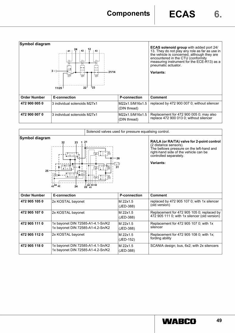
49
Components ECAS 6.
Symbol diagramECAS solenoid group with added port 24/13. They do not play any role as far as use in the vehicle is concerned, although they are encountered in the CTU (conformity measuring instrument for the ECE-R13) as a pneumatic actuator.
Variants:
Order Number E-connection P-connection Comment
472 900 005 0 3 individual solenoids M27x1 M22x1.5/M16x1.5
(DIN thread)
replaced by 472 900 007 0; without silencer
472 900 007 0 3 individual solenoids M27x1 M22x1.5/M16x1.5
(DIN thread)
Replacement for 472 900 005 0; may also replace 472 900 013 0; without silencer
Solenoid valves used for pressure equalising control.
Symbol diagramRA/LA (or RA/TA) valve for 2-point control (2 distance sensors). The bellows pressure on the left-hand and right-hand side of the vehicle can be controlled separately.
Variants:
Order Number E-connection P-connection Comment
472 905 105 0 2x KOSTAL bayonet M 22x1.5
(JED-388)
replaced by 472 905 107 0; with 1x silencer (old version)
472 905 107 0 2x KOSTAL bayonet M 22x1.5
(JED-388)
Replacement for 472 905 105 0; replaced by 472 905 111 0; with 1x silencer (old version)
472 905 111 0 1x bayonet DIN 72585-A1-4.1-Sn/K2
1x bayonet DIN 72585-A1-4.2-Sn/K2M 22x1.5
(JED-388)
Replacement for 472 905 107 0; with 1x silencer
472 905 112 0 2x KOSTAL bayonet M 22x1.5
(JED-152)
Replacement for 472 905 108 0; with 1x; fording ability
472 905 118 0 1x bayonet DIN 72585-A1-4.1-Sn/K2
1x bayonet DIN 72585-A1-4.2-Sn/K2M 22x1.5
(JED-388)
SCANIA design; bus, 6x2; with 2x silencers
2322
3
41 4212
21/14
43
11/25
24
23
22
31
4442
1 21
43
25
24
32
26
44 4243
41

50
ComponentsECAS6.
Symbol diagramRA/LA (or RA/TA) valve for 2-point control (2 distance sensors). The bellows pressure on the left-hand and right-hand side of the vehicle can be controlled separately.Special feature: Lifting axle is lifted/lowered inversely (i. e. opposite). Replacing the following valves with the previously mentioned valves is not permissible.
Variants:
Order Number E-connection P-connection Comment
472 905 110 0 2 solenoid blocks M27x1 M 22x1.5
(JED-152)
replaced by 472 905 116 0; housing identified by a blue paint dot on the cover; 1 silencer
472 905 116 0 1x bayonet DIN 72585-A1-4.1-Sn/K21x bayonet DIN 72585-A1-4.2-Sn/K2
M 22x1.5
(JED-388)
Replacement for 472 905 110 0; housing identified by a blue paint dot on the cover; with 1x silencer.
Symbol diagramRA/LA (or RA/TA) valves for 1-point control (1 distance sensor). These valves have a throttle (diameter 0.6 mm) between the pneumatic outputs to the left and right side of the bellows. The bellows pressure on the left-hand and right-hand side of the vehicle cannot be controlled separately.
Variants:
Order Number E-connection P-connection Comment
472 905 109 0 2x KOSTAL bayonet M 22x1.5(JED-388)
replaced by 472 905 114 0; with 2x silencers
472 905 114 0 1x bayonet DIN 72585-A1-4.1-Sn/K21x bayonet DIN 72585-A1-4.2-Sn/K2
M 22x1.5(JED-388)
Replacement for 472 905 109 0; with 2x silencers
Solenoid valves with special tasks for particular users.
Symbol diagramFA/RA valves for 1-point control / 1-point control with integrated lifting bellows control (2 distance sensors).Such a valve can carry out all the ECAS functions in a 6x2 vehicle with full air suspension and a lifting axle. There is one output available in each case for the front, rear and lifting axle supporting bellows. The lifting bellows has a separate output on the valve and does not have constrained control.
Order Number E-connection P-connection Comment
472 905 070 0 2 solenoid blocks M27x1 M22x1.5 (JED-388) 1X (JED-152)
w/o silencer
23
22
31
1 21
62.4
25
24
32
26
62.162.2
62.3 62.4
62.1
62.3 62.2
23
22
31
1 21
25
24
32
26
61.4 61.361.1
62.462.362.1
24
21
31
1
22
25
32
26
61.4
61.3
61.162.462.162.2
62.3
61.2

51
Components ECAS 6.
6.4 The remote control unit
Using the remote-control, you have the following
options:
• to change the desired level,
• to adjust the position of the lifting axle,
• to activate traction help,
• to preselect the desired normal level.
The ride height can be adjusted only while at a standstill
or moving no faster than a limit speed vOPER
.
– The ECU is informed of this limit speed when you set
the parameters.
Ideally, the remote control unit should be accommodated
in a housing. The remote control unit is linked to the ECU
using a flexible 4-core helix cable and a socket on the
vehicle.
The 4-core cable is assigned as follows:
• Terminal 15 for the voltage supply
• Terminal 31
• CLOCK line (also: pulse line)
• Data line (also: data line)
Fig. 42 shows the remote control unit 446 056 117 0 for a
vehicle with full air suspension and a lifting axle. The
functions of this RCU are:
• Adjusting to normal level.
• Lowering and raising of the vehicle body
simultaneously above all axles; separately above the
front or rear axle, or multi-axle combination, and, if the
system is designed accordingly, separately on the
axle's right and left side.
• Raising and lowering the lifting axle and thereby
switching off or on any fully automatic lifting axle
operation, and reducing or increasing the load on the
trailing axle.
• Storing up to two preference (i.e. memory) levels and
adjusting these levels by briefly pushing the
appropriate button.
• Setting the vehicle to STAND-BY operation during
which the power supply for ECAS is provided by
terminal 30.
• pressing the STOP button will cancel any lifting and
lowering processes immediately.
Systems with less comprehensive configurations will not
react to button commands that are not consistent with the
actual system. For example: selection of a front axle in a
vehicle with partial air suspension, because these
vehicles do not have a front axle with air suspension.
With a remote control unit for vehicles with full air
suspension, on the other hand, it is perfectly possible to
operate a vehicle with partial air suspension.
Layout of the remote control unit
The top row of the operating panel contains three
indicator lamps. They indicate which axle has been
preselected for an adjustment.
RA valve for 1-point control (1 distance sensor)
Symbol diagram Order Number E-connection P-connection Comment
472 905 010 0 1x KOSTAL bayonet
1/2-14 DRYSEAL NPTF
12 V design: with silencer
221
31
6.4 6.26.3
RA/TA valve for 1-point control (1 distance sensor)
Symbol diagram Order Number E-connection P-connection Comment
472 905 060 0 1x KOSTAL bayonet
1/2-14 DRYSEAL NPTF
12 V design: with silencer
22
1
31
6.4
6.2
6.3
26
6.1

52
The second row of the control panel contains three
preselect buttons: front axle (left side of vehicle), rear
axle (right side of vehicle), lifting axle. Each of these
buttons is located below the corresponding indicator
lamp.
– Press the desired preselect button.
The corresponding lamp will light up, indicating that it is
now possible to perform an action on the preselected
axle.
– Press the same preselect button again.
The corresponding indicator lamp goes out, indicating
that input mode for the remote control unit has been
terminated.
It is no longer possible to make changes using the
remote control unit.
Desired level changes relating to the entire vehicle are
desired:
– Press and hold the preselect buttons 'front axle' and
'rear axle'.
Both indicator lamps (for the front and the rear axle) must
light up to indicate that the axles are ready for actuation.
Generally, any input using the remote control unit is
initiated by preselecting the desired axle(s) and ends
by cancelling the input mode.
Lifting and lowering the vehicle body
– Press and hold the LIFT or LOWER button.
A modified desired level for the vehicle body section
located above the preselected axles is preset for the
ECU. The vehicle body now immediately adjusts its
distance to the vehicle axle for as long as the button is
pressed and held.
– Release the button or press the STOP button.
The procedure for changing the nominal value is
terminated. The nominal value detected the moment that
the button was released is used as the new nominal
value, and levels are adjusted accordingly.
Lifting and lowering the lifting axle
– Press the preselect button 'lifting axle' and then briefly
tap the LIFT or LOWER button.
The lifting axle is raised or lowered, or the trailing axle is
loaded or relieved. Lifting or loading action is only
possible if the defined permitted maximum pressure in
the main axle's support bellows is not exceeded.
Lowering the lifting axle, or relieving the trailing axle,
triggers deactivation of automatic lifting/trailing axle
operation.
Deactivation of automatic lifting/trailing axle
operation
The automatic lifting/trailing axle operation can be
switched off, provided that at least one lifting/trailing axle
was automatically lifted/relieved owing to a light load.
!
!
ComponentsECAS6.
preselect button 'front
axle' or left side of the
vehicle if right/left control
is available
Memory level 2
button M 2
Memory level 1
button M 1
LIFT button
LOWER button
Indicator lamp
Front axle
Indicator lamp
Rear axle
Indicator lamp
Lifting axle
Preselect button 'rear axle'
or right side of the vehicle if
right/left control is available
Preselect button 'lifting axle'
Normal level button
Stop button Abb. 42 Remote control unit 446 056 117 0 and its components
53
– Press the LOWER button.
Deactivating automatic lifting axle operation means that
the previously (automatically) raised lifting axle is
lowered, or that load is placed on the previously relieved
trailing axle.
Switching on automatic lifting/trailing axle operation
– Press the preselect button 'lifting axle' and then press
the LIFT button.
– by switching the ignition on and off.
Normal levels
A brief tap on the 'normal level' button is sufficient for
adjustment to the current normal level. In some systems
there is no need to deactivate the axle preselection as
this is done automatically.
Memory levels
A specific ride height setting is frequently required during
loading or unloading operation.
You have the option to save this level and to apply it as
often as required, simply by pressing a button.
– Press the STOP button and simultaneously press
either the M1 or the M2 button.
This saves an existing desired level as a memory (or
'preferential') level.
The stored values are not lost when the ignition is
switched off. These values apply to the entire vehicle, so
you only need to preselect an axle and retrieve the
setting.
– Tap the corresponding button M1 or M2.
The vehicle body is immediately adjusted to the stored
level.
Stop
– Press the STOP button.
All levelling control processes are stopped immediately,
and the present level is recognised as the desired level.
The Stop function is designed, above all, to permit
cancelling any level changes currently under way
(memory, driving level) should you consider
continuation of the process hazardous.
In some systems, pressing the STOP button is obligatory
to terminate the LIFT and LOWER functions.
– Switch off ignition while you press and hold the STOP
button.
The vehicle is in STAND-BY mode.
Speed dependency
The "Raising and lowering of the vehicle body" and
"Memory level" functions can be used only when the
vehicle is either stationary or has not exceeded a
preselected speed vOPER
. Any control processes which
were started below that speed will be completed even at
greater speed.
Pressing several buttons simultaneously
If several buttons are pressed simultaneously and these
do not represent a plausible combination, no command
will be accepted when a targeted level change is
initiated. The STOP function is executed.
Disconnecting the remote control unit
– Disengage the remote control unit.
The STOP function is triggered immediately.
Using several remote control units
A second remote control unit (on the loading platform,
for example, or outside the vehicle) may be provided for
controlling ECAS.
To ensure that only one of these remote control units
communicates with the electronic system, a selection
switch must be installed on the DATA line leading to the
ECU for selecting one of the two remote control units.
This also applies if more than two remote control units
are used.
Do not connect two concurrent remote control
units to the ECU in parallel. Such a procedure is
impermissible and will cause malfunctions.
Priority
The remote control unit has a high priority within the
system. If the unloading level function has been activated
and a LIFT/LOWER command is also entered via the
remote control unit, it is the command from the remote
control unit will be executed.
In the event that the LIFT/LOWER function fails, the
vehicle body can still be adjusted to a reasonable level as
a makeshift solution for the vehicle to be driven to the
workshop.
– ECAS needs to be aware of the existence of a remote
control unit. For this reason, the remote control unit
must be connected to the ECU before the system can
be put into operation.
Service issues for remote control units
Depending on the system configuration, there are
approximately 60 different remote control unit variants
available. These differ with regard to development stage,
functional range, connector layout, and vehicle
manufacturer's logo. This wide variety, however, can be
Components ECAS 6.

54
ComponentsECAS6.
reduced to a few basic variants. Should the unit need to
be replaced, the procedure is therefore straightforward.
6.4.1 Remote control unit for vehicle combination
446 056 25 . 0
The remote control unit for the vehicle combination is
used for manual levelling control, as well as lifting axle
control, for vehicles equipped with ECAS. These units
also include ECUs with integrated ECAS functionality,
such as TCE system for example.
• With this device it is possible to control the level of the
towing vehicle and trailer vehicle body, provided that
the ECAS systems in the vehicle sections support this
function.
• The device can be installed in any vehicle type.
Drawbar trailer as well as semitrailer vehicles/units
are supported.
• The remote control unit may be used equally in
conjunction with the ECAS system of the trailer and/or
the towing vehicle.
The user thus has the option to control the level of the
entire vehicle using only a single operating device that is
easily managed and robust.
Separate axle preselection buttons are provided for
targeted selection of all vehicle axles, or groups of axles,
in any combination. Selected axles are indicated by a
corresponding indicator lamp. Easily understood
symbols and colours for special buttons facilitate intuitive
operation.
A tough, flexible four-core helix cable, which is securely
fixed on the device, is used to establish a connection to
the ECU. A mounting bracket is available under the
WABCO no. 446 056 010 4. It is recommended that the
device is placed back into the holder if it is not used.
Remote control unit Replacement
446 056 000 0, 446 056 007 0,
446 056 011 0, 446 056 014 0,
446 056 016 0, 446 056 017 0,
446 056 018 0, 446 056 021 0,
446 056 024 0, 446 056 027 0,
446 056 028 0, 446 056 029 0,
446 056 032 0, 446 056 035 0,
446 056 116 0, 446 056 124 0,
446 056 127 0, 446 056 128 0,
446 056 129 0, 446 056 132 0,
446 056 135 0, 446 056 136 0,
446 056 137 0, 446 056 140 0,
446 056 141 0, 446 056 142 0,
446 056 143 0
446 056 117 0
446 056 202 0
446 056 002 0, 446 056 005 0,
446 056 009 0
446 056 102 0
446 056 012 0, 446 056 013 0 446 056 113 0
446 056 015 0 446 056 115 0
446 056 019 0, 446 056 020 0, 446
056 119 0
446 056 120 0
446 056 008 0, 446 056 025 0 446 056 125 0
446 056 030 0 446 056 130 0
446 056 033 0, 446 056 034 0, 446
056 133 0
446 056 134 0
446 056 138 0 446 056 139 0
446 056 026 0, 446 056 031 0,
446 056 126 0, 446 056 131 0
446 056 146 0
Abb. 43 Remote control unit 446 056 250 0
Button assignment (for functions refer to 6.4)
1 Indicator lamp, front axle towing vehicle
2 Indicator lamp, rear axle towing vehicle
3 Indicator lamp, front axle trailer
4 Indicator lamp, rear axle trailer
5 Preselect button, lifting axle trailer
6 Preselect button, lifting axle towing vehicle
7 Normal level button
8 Stop button STOP
9 LOWER button
10 Memory level 2 - button M 2
11 Preselect button, rear axle towing vehicle
12 Preselect button, rear axle trailer
13 LIFT button
14 Memory level 1 - button M 1
15 Preselect button, towing vehicle
16 Preselect button, front axle trailer
1 2 34
5
6
7
89
10
11
12
13
14
15
16