Download-manuals-surface water-waterlevel-22howtocarryoutprimaryvalidationofwaterleveldata

ELEKTRONIKA IR ELEKTROTECHNIKA, ISSN 1392-1215, VOL. 22, NO. 5, 2016
1Abstract—In this paper development and testing of awireless sensor node that is powered by solar energy harvestingis described. Implemented wireless sensor node ischaracterized by low cost and consumption, long mean timebetween maintenance, simplicity, flexibility, modularity andminiature design in applications for monitoring ofenvironmental parameters. As a replacement for relativelyexpensive battery supply and in order to minimizemaintenance costs, energy harvesting solution that uses aminiature solar panel and supercapacitor is tested. This node isused for measurements of water levels of surface andunderground waters for application in agriculture. For thispurpose the node is expanded with a capacitive sensor formeasurement of water levels, which is particularly discussed inthis paper as simple and innovative solution.
Index Terms—Capacitive sensor; energy harvesting;wireless sensor networks; environmental monitoring;supercapacitor.
I. INTRODUCTION
Research in the field of wireless sensor networks (WSNs)has contributed to many areas such as disaster management,automotive, infrastructure monitoring, security andsurveillance, etc. In recent decades, numerous examples ofthe application of WSNs for environmental monitoring haveemerged [1]–[3]. Environmental protection requiresenormous financial resources, but potential investors do notfind interest to invest since this field is not profitable at themoment. Therefore, the tendency is to invest a minimum ofresources in low-cost systems for monitoring ofenvironmental parameters with not optimal, but satisfactoryperformance. Overall, WSNs for environmental monitoringare considered to be of higher quality if they meet thefollowing requirements: low price, reliable operation inremote field conditions, adaptability to specific applicationrequirements, and a negligible impact on the environment.
The problem of excess waters in the AutonomousProvince of Vojvodina, Serbia, is a typical example whereemploying WSNs could provide information that has aneffect on increase in agricultural production. Althoughduring the course of the last two centuries extensive
Manuscript received 19 December, 2015; accepted 16 July, 2016.This research was funded by the III43008 project from the Ministry of
Science and Education of the Republic of Serbia.
measures have been undertaken, there were many climateextremes in the last decades which directly affect on theproblem of excess water. Whether due to flooding or due toincreased precipitation, a certain part of fertile arable land isunusable. Today, the Vojvodina region has a network ofalmost 20000 km of drainage canals [4]. Due to insufficientfunding, this drainage network is poorly maintained, whichoften increases the overall damage caused by naturaldisasters. Information collected by monitoring of waterlevels in drainage canals can be used for timely responseand prevention in case of future climate extremes or forirrigation management in normal conditions. Generally,continuous measurement of groundwater level on number ofpoints over long periods of time (several years) with usageof hydrodynamic models, some excess water types could beforecasted, and actions could be taken [5].
Successful implementations of WSNs for water levelmonitoring already exist [5]–[8]. In this paper, a wirelesssensor node which is characterized by simplicity, low costand ease of installation is described. Dedicated hardwaredesign enables ultra-low power consumption in comparisonwith commercial solutions. In addition, with the selection ofspecial electronic components, the price per node isdrastically reduced, as well as dimensions. Since theprimary intention is to use a sensor node for measuring ofenvironmental parameters in inaccessible terrains, solarenergy harvesting has been added. Using energy harvestingcombined with a supercapacitor as a storage element, thebattery supply becomes unnecessary, which contributes tomaintenance costs reduction. Detailed description of node isgiven in Section II. In Section III, it is shown how basicnode is upgraded with an expansion board for themeasurement of small capacitance. The process how to use asimple two-wire cable for measurement of water levels isexplained. Section IV shows results of testing a sensor inreal application followed by conclusion in Section V.
II. IMPLEMENTATION OF WIRELESS SENSOR NODE WITHENERGY HARVESTING SUPPORT
In practice only wealthy countries spend significantresources for environmental protection. This is the mainreason why the minimization of costs is required in thedesign. One way to achieve this includes design of dedicated
Surface and Underground Water LevelMonitoring Using Wireless Sensor Node with
Energy Harvesting SupportZivorad Mihajlovic1, Vladimir Milosavljevic1, Ana Joza1, Vladimir Rajs1,
Mirjana Damnjanovic1, Milos Zivanov1
1Faculty of Technical Sciences, University of Novi Sad,Trg Dositeja Obradovica 6, 21000 Novi Sad, Serbia
http://dx.doi.org/10.5755/j01.eie.22.5.16346
62

ELEKTRONIKA IR ELEKTROTECHNIKA, ISSN 1392-1215, VOL. 22, NO. 5, 2016
hardware, resulting in a lower cost of a single sensor nodeand lower power consumption. The prices of installation andmaintenance will be reduced as well. As a consequence theprice of whole WSNs will be decreased.
A. Dedicated Hardware Design of the NodeBased on above defined requirements, a wireless sensor
node is designed, and the block diagram of hardwarestructure is shown in Fig. 1. Control and communicationsystems are based on commercial componentsMSP430G2553 microcontroller (MCU) and nRF24L01+ RFtransceiver, because they already proved to be an excellentchoice for low-power and low-cost WSNs [9].MSP430G2553 is a mixed signal MCU that is characterizedby the following features: very low power consumption,ultra-fast wake-up time from standby mode (less than 1 μs),and a multitude of peripherals. This MCU is a popularchoice of embedded system designers, which enables easyprototyping with lots of documentation available.
The low-cost nRF24L01+ from Nordic Semiconductor isa single chip RF transceiver for the global, license-free2.4 GHz ISM band. It can provide very high speedcommunications (up to 2 Mbps) with extremely low powerconsumption (the RX current is just 13.5 mA). Outputpower, frequency channels, and protocol setup are easilyprogrammable through serial peripheral interface (SPI) ofMSP430G2553 MCU. Current consumption for differentoperating modes is given in Table I.
Fig. 1. Hardware subsystems and the most important componentsincorporated into wireless sensor node.
Since the node is designed for applications in the field ofenvironmental protection, sensors for pressure, temperatureand humidity, as well as EEPROM for storing additionaldata are included in design. By introduction of these sensorswriting firmware and node testing in real conditionsbecomes easier. The sensors are selected in accordance withthe requirements of minimum consumption and low cost.
The Si7020-A20 sensor from Silicon Labs consists ofprecision relative humidity sensor (± 4%) and high accuracytemperature sensor (± 0.4 °C) with I2C interface and3x3 mm2 package size. The MPL3115A2 from FreescaleSemiconductor is a MEMS sensor with an I2C interface thatprovides accurate measurements of pressure, altitude andtemperature. For additional sensors there is an expansionport available. All MCU interfaces, except SPI, are availableon this port. In this paper, the expansion port is used toattach capacitive sensor for water level measurement.
Total cost of developed node is about 20 Euros which isless expensive compared to most commercial solutions [10].
Unfortunately, simpler and less expensive hardware is notsuitable for more complex WSNs routing protocols.
TABLE I. CONSUMPTION OF THE MOST IMPORTANTCOMPONENTS OF NODE WITH APPROXIMATE PRICES.
Component OperatingMode Consumption Price
MSP430G2553 Active 230 µA (1 MHz) 0.95€Standby 0.5 µA
NRF24L01+Active 11.3 mA TX at 0 dBm
13.5 mA RX at 2 Mbps1.44€
Standby 26 µAPower down 900 nA
Si7020 Active 150 µA 3.12€Standby 60 nA
MPL3115 Active 2 mA 1.82€Standby 2 µA
24AA1025T Active 450 µA 2.57€Standby 5 µA
BQ25504 Quiescent 330 nA 2.45€
With a consumption of about 4 μA (without EEPROM) instandby operating mode and average consumption of aboutfew milliamps in active mode (without communicationtask), implemented node is very good low-power solutionand can be considered as better, compared to somecommercial solutions [10]–[12]. However, since our mainobjective is to measure different environmental parameters,it is necessary to include consumption of sensors attached tothe node. Although the tendency is to reduce theconsumption of the sensor as much as possible, in practicethis is often impossible. Also, when measuring certainparameters, it is necessary to supply sensors for a period oftime (e.g. heating of gas sensors). Battery supply in suchcases will be quickly depleted. Energy harvesting is anefficient replacement for batteries in the field ofenvironmental monitoring.
B. Implementation of Solar Energy HarvestingIn addition to the low price and consumption, an
important requirement for node design is to minimizemaintenance costs after installation of WSNs. Commercialnodes generally use some form of battery power, which,depending on the node type, can last for a very long time,even up to several years. The batteries as limited energysource must be optimally used for both processing andcommunication tasks. Since communication task tends todominate over the processing task in order to make optimaluse of energy, the amount of communication should bereduced as much as possible. In practical applications, thewireless sensor nodes are usually deployed in hostile orunreachable terrains where they cannot be easily retrievedfor the purpose of replacing or recharging the batteries,therefore the lifetime of the network is usually limited.When the battery is finally depleted, it is necessary to investadditional resources in their replacement and expensive fieldwork in harsh conditions for recovery of relatively largenumber of nodes. Furthermore, the batteries themselvesincrease the cost, especially if the specific battery types withhigh capacity and low self-discharge current are used.
Given the above, it can be concluded that in order toreduce cost of WSNs, it is necessary to find a way tominimize maintenance costs. The easiest way to reducecosts is to increase the time between two battery
63

ELEKTRONIKA IR ELEKTROTECHNIKA, ISSN 1392-1215, VOL. 22, NO. 5, 2016
replacements. This can be achieved in two ways. Firstly, thecapacity of energy source should be increased, butdimensions of the node must remain the same. In otherwords, the energy density of the source must be increased,but unfortunately the technology of battery production islimited at the moment. Secondly, the power consumptionshould be minimized, either by selecting more efficientcomponents or by firmware optimization. In many cases,hardware implementation is already optimized for ultra-lowpower application, and by firmware optimization only slightimprovements can be achieved.
In this paper, the third option that includes energyharvesting is considered, allowing a node to generate itsown power from the ambient. Energy harvesting involvestechniques that capture, harvest or scavenge unused ambientenergy (such as kinetic, thermal or electromagnetic) andconvert it into usable electrical energy that is stored andlater used for node operation. Energy harvesting subsystemconsists of energy source, energy harvester, powermanagement circuit and energy storage element (Fig. 1).More information about energy harvesting technologies,models and possible applications can be found in [12]–[15].
In this paper, harvesting subsystem with the miniaturesolar panel (photovoltaic cell) as energy source was used.Energy harvesting with photovoltaic cells is popular andwell-studied [16]–[19]. Photovoltaic cells are the mostpopular choice because of their availability and relativelyhigh performance in comparison to the other energyharvesting techniques [17]. However, solar powertechnology is still expensive, so it is important to maximizethe power output. In order to improve the efficiency ofphotovoltaic cell, methods such as maximum power pointtracking (MPPT) are used. There are many types of MPPTtechniques. These techniques differ in many aspects,including complexity, convergence speed, hardwareimplementation, sensors required, cost, range ofeffectiveness and need for parameterization [20]. MPPTcircuit operates on the basis of the maximum power transfertheorem to extract as much power as possible by impedancematching, in order to compensate for the varyingcharacteristic resistance of solar panels, thus providinghigher power outputs.
In our implementation, energy harvesting circuit based onan integrated chip BQ25504 from Texas Instruments is used.The BQ25504 is an ultra-low power charging controllerintended for interfacing DC sources such as solar cells,thermal generators and high-impedance batteries. Controlleruses the open-circuit voltage (OCV) technique to regulatethe solar cell to its maximum power point (MPP) [20]. TheMPPT circuit obtains a new reference voltage every 16 s(typical) by periodically disabling the charger for 256 ms(typical) and sampling a fraction of the harvester's open-circuit voltage. For solar harvesters, the MPP is typically70 %–80 % of open-circuit voltage. For the solar panel theoutput power in function of voltage is not linear function[18]. The exact ratio for MPPT can be optimized to meet theneeds of the input source being used by connecting externalresistors divider. BQ25504 controller is an all in onesolution for energy harvesting, but it requires anunderstanding of the settings for a successfulimplementation. Among other parameters it is possible to
adjust the undervoltage threshold (VBAT_UV) to preventstorage component to be deeply discharged or damaged(Fig. 2). Also, the overvoltage protection (VBUT_OV) isconfigurable. As information that the controller is ready andthat the voltage has reached the operational value a digitaloutput signal (VBAT_OK) is used. This signal can awakeMCU from sleep operating mode by using interrupt serviceroutine. Both signal level and hysteresis (HYST) are easilyconfigurable via external resistors. The load is not directlyconnected to the storage element, but internally via aMOSFET. The controller on the basis of the externalresistors values and internal references regulates the flow ofpower to and from the storage element. The whole process isshown in Fig. 2. When the input voltage of controllerexceeds the minimum input voltage with sufficient power,the cold-start subsystem turns on. The cold-start subsystemis essentially an unregulated boost converter. When thestorage capacitor voltage reaches 1.8 V, the main boostregulator starts up, and charging the storage element beginswhen the output voltage of the controller reachesVBAT_UV_HYST (2.10 V + 80 mV). The load is beingsupplied when output voltage reaches VBAT_OK_HYST(2.45 V). Controller turns off when it reaches VBAT_OV(3.53 V), when the overvoltage protection is activated. Inthe opposite direction, when the output voltage drops belowovervoltage threshold VBAT_OV_HYST (3.53 V–35 mV)charging resumes. When output voltage drops belowVBAT_OK (2.20 V), the load is separated from thecontroller, but the charging continues until the outputvoltage falls below VBAT_UV (2.10 V). The adjustedvoltage range (2.20 V to 3.53 V) corresponds to the workingvoltage range of MSP430G2553 (2.00 V to 3.60 V). In thisway the energy in the storage element is maximally utilized.
Fig. 2. Relative positions of the threshold voltages that affectcharging/discharging of the storage element.
C. Supercapacitor as Storage ElementThe node described in this paper is designed for use in the
field conditions for monitoring of environmental parameters.Most of the environmental parameters are changing slowly,which means that frequent measurement is not necessary.When measurement of surface and underground water levelsis considered, situation is even more favourable. Undernormal conditions when there are no serious changes inwater levels, sending data several times per day is sufficient.In the case of sudden changes in water levels, the nodesends emergency information. Therefore, a large capacitypower source is not necessary.
For requirements of low power consumption and low
64
ELEKTRONIKA IR ELEKTROTECHNIKA, ISSN 1392-1215, VOL. 22, NO. 5, 2016
frequency data transmissions, supercapacitor is chosen asenergy storage. Supercapacitor technology is constantlyevolving, so their application increases as well. More detailsabout the analysis and application of supercapacitor inWSNs can be found in [21]–[22]. In our hardwareimplementation Murata supercapacitor with capacitance of0.47 F and nominal voltage of 4.20 V is used (Fig. 1).Miniature dimensions, especially small thickness aresuitable for the design of multi-layered modular structures.
The maximum consumption of node is practically equalto the consumption of the communication module(11.30 mA for transmission). The node consumption instandby operating mode is less than 4 μA. Forsupercapacitor that discharges from 3.53 V to 2.20 V(Fig. 2), testing has shown that the node is operational forseveral days without charging in a case when thecommunication task is executed once per hour. The changesof voltage in case when communications occur once persecond, once per ten seconds and once per ten minutes areshown in Fig. 3. In this experiment the supercapacitor ischarged to the maximum value (3.53 V), and then the solarpanel is disconnected. The MCU is awakened in exactlyspecified intervals when the voltage on the supercapacitor ismeasured and then sends the measured value via radiocommunication. Upon the completion of transmission, theMCU returns to sleep operating mode.
Fig. 3. Measured voltage on supercapacitor for different frequencies ofcommunication task. Equivalent resistances of 11 kΩ, 70 kΩ and 220 kΩare calculated with Micro-Cap simulator.
It may be noted that in the case of sending data once per10 seconds, the energy from the supercapacitor is sufficientto supply the sensor node almost 12 hours. For less frequenttransmission, energy from the supercapacitor is sufficientfor the operation during a few days or even more. Of course,this mode will not occur in practice because the node will berecharged at the first light in the morning.
Using Micro-Cap circuit simulator, supercapacitorvoltage curves fitted to experimental data are obtained.Average power consumption is modelled with resistorwhose value depends on frequency of communication task.Calculated values are 11 kΩ, 70 kΩ and 220 kΩ forfrequencies of communication tasks shown in Fig. 3. Thissimplifies estimation of supercapacitor discharge time. Also,in the reverse direction equivalent resistance can be used tocalculate the optimum frequency of the communication task.
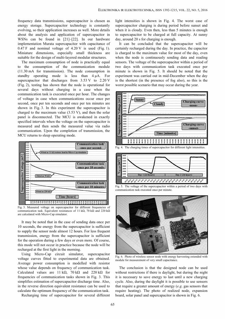
Recharging time of supercapacitor for several different
light intensities is shown in Fig. 4. The worst case ofsupercapacitor charging is during period before sunset andwhen it is cloudy. Even then, less than 5 minutes is enoughto supercapacitor to be charged at full capacity. At sunnyday, around 20 s for charging is enough.
It can be concluded that the supercapacitor will becertainly recharged during the day. In practice, the capacitoris charged to the maximum value for most of the day, evenwhen the node is continuously sending data and readingsensors. The voltage of the supercapacitor within a period oftwo days with communication task executed once perminute is shown in Fig. 5. It should be noted that theexperiment was carried out in mid-December when the dayis the shortest (in the presence of fog also), so this is theworst possible scenario that may occur during the year.
Fig. 4. The charging times of supercapacitor for different light intensities.
Fig. 5. The voltage of the supercapacitor within a period of two days withcommunication task executed once per minute.
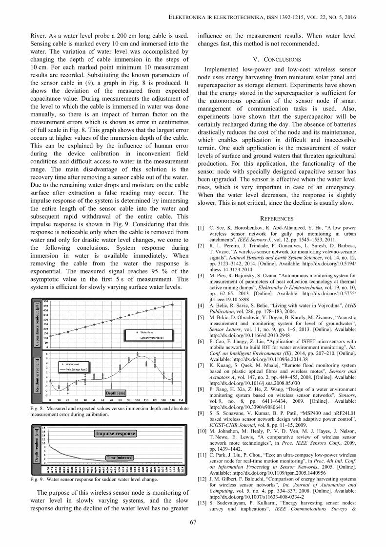
Fig. 6. Photo of wireless sensor node with energy harvesting extended withmodule for measurement of very small capacitance.
The conclusion is that the designed node can be usedwithout restrictions if there is daylight, but during the nightit is necessary to save energy to last until a new chargingcycle. Also, during the daylight it is possible to use sensorsthat require a greater amount of energy (e.g. gas sensors thatrequire heating). The photo of realized node, expansionboard, solar panel and supercapacitor is shown in Fig. 6.
65

ELEKTRONIKA IR ELEKTROTECHNIKA, ISSN 1392-1215, VOL. 22, NO. 5, 2016
III. CAPACITIVE SENSOR FOR WATER LEVELMEASUREMENT
For water level measurement simple expansion boardbased on PIC12F1822 MCU from Microchip is designed(Fig. 6). In order to reduce the consumption, a load switchintegrated circuit TPS22944 from Texas Instruments is used.The main MCU uses switch to control power supply of theextension board. When measurement of the water level isnot performed, the consumption of the hardware section thatexecutes this task is practically reduced to zero. When usinglimited resources of alternative energy, this represents asignificant advantage in node’s performance. This is arecommended method to extend functionality of the node.
The measurement setup where expansion board is addedto wireless sensor node is shown in Fig. 7. PIC12F1822 hasintegrated capacitive sensing (CPS) module, which issuitable for measuring small capacitance values. Two-wirecable, which represents a capacitive sensor, is added to theexpansion board. Capacitance sensing method is chosen dueto its reliable operation, low cost and because it has nomoving parts. Two-wire cable acts as a water level probethat is immersed inside water and it can be made from anycable type that is isolated at bottom side. This water levelprobe is connected to MCU’s CPS module. No signalconditioning electronics is needed between sensing probeand MCU which makes hardware design extremely simple.
Capacitance of isolated cable partially immersed in wateris read by MCU’s CPS oscillator module. Cable acts as thecapacitor (CCABLE), which capacitance changes linearly withlength of the cable section immersed in water. Dielectricconstant around cable changes (εr), which results in theequivalent cable capacitance change. The time dependenceof the capacitor voltage (VCABLE) can be described with
101 0
1( ) ( ) ( ) .tCABLE CABLE t
CABLEV t V t i t dt
C (1)
Fig. 7. Wireless sensor node with expansion board that measures thecapacitance of two-wire cable immersed in water.
By using constant current (1) is simplified to
1 0 1 0( ) ( ) ( ).CPSCABLE CABLE
CABLE
IV t V t t tC
(2)
If we take into account the fact the charging anddischarging currents (ICPS) are the same, by measuring thefrequency of oscillation of the CPS oscillator, we canexpress rise (tRISE) and fall time (tFALL) as
1 .2FALL RISE
CPSt t
f
(3)
Cable capacitance per unit length is specified bymanufacturer, in the air (C'A) is 55.13 pF/m, and in the water(C'W) is 296.33 pF/m.
The total capacitance to be measured is:
0 ,EKV A A W WC C L C L C (4)
0 ( ) ,EKV C W A W WC C L L C L C (5)
where C0 denotes parasitic capacitance of the PCB tracksand the cable connector, LA is the length of the cable in theair, LW is the length of the cable immersed in the water andLC is the total length of the cable. The firmware measuresthe operating frequency of the CPS oscillator. The totalmeasured capacitance (CEKV) can be determined using
1 0
1 0
( ) ,( ) ( )
CPSEKV
C C
I t tCV t V t
(6)
where t1 represents the moment of reaching a positivereference voltage of CPS oscillator, while t0 is the momentof reaching negative reference voltage of CPS oscillator.Thus (6) comes down to
.( ) 2
CPS RISE CPSEKV
CPS
I t ICV V V V f
(7)
In this paper the following configuration of CPS oscillatoris used: V+ = 2048 mV which is the internal referencevoltage and V− = 10/32·2048 mV.
The negative reference is obtained by using an internal 5-bit DAC converter which also uses the internal referencevoltage of 2048 mV. The current source of CPS oscillator isadjustable by software and is set to 9 μA.
Substituting these values in (7), the expression for thecapacitance of the sensor cable is calculated with
63.196 10 .EKVCPS
Cf
(8)
Using (5), the water level can be calculated, i.e. the lengthof cable immersed in water
0 .EKV C AW
W A
C C L CLC C
(9)
The reference capacitor of 470 pF capacitance and 5%tolerance was added on the expansion board for testingpurposes. In this case due to the short conductive track linesC0 can be neglected. By measuring the frequency of the CPSoscillator for this channel, the value of 6885 Hz is obtainedand using (8) the measured capacitance value of 464.20 pFis calculated. This value represents a deviation of 1.27 %that is within the tolerance value of testing capacitor used.
IV. RESULTS AND ANALYSIS
The device was tested in a calm section of the Danube
66
ELEKTRONIKA IR ELEKTROTECHNIKA, ISSN 1392-1215, VOL. 22, NO. 5, 2016
River. As a water level probe a 200 cm long cable is used.Sensing cable is marked every 10 cm and immersed into thewater. The variation of water level was accomplished bychanging the depth of cable immersion in the steps of10 cm. For each marked point minimum 10 measurementresults are recorded. Substituting the known parameters ofthe sensor cable in (9), a graph in Fig. 8 is produced. Itshows the deviation of the measured from expectedcapacitance value. During measurements the adjustment ofthe level to which the cable is immersed in water was donemanually, so there is an impact of human factor on themeasurement errors which is shown as error in centimetresof full scale in Fig. 8. This graph shows that the largest erroroccurs at higher values of the immersion depth of the cable.This can be explained by the influence of human errorduring the device calibration in inconvenient fieldconditions and difficult access to water in the measurementrange. The main disadvantage of this solution is therecovery time after removing a sensor cable out of the water.Due to the remaining water drops and moisture on the cablesurface after extraction a false reading may occur. Theimpulse response of the system is determined by immersingthe entire length of the sensor cable into the water andsubsequent rapid withdrawal of the entire cable. Thisimpulse response is shown in Fig. 9. Considering that thisresponse is noticeable only when the cable is removed fromwater and only for drastic water level changes, we come tothe following conclusions. System response duringimmersion in water is available immediately. Whenremoving the cable from the water the response isexponential. The measured signal reaches 95 % of theasymptotic value in the first 5 s of measurement. Thissystem is efficient for slowly varying surface water levels.
Fig. 8. Measured and expected values versus immersion depth and absolutemeasurement error during calibration.
Fig. 9. Water sensor response for sudden water level change.
The purpose of this wireless sensor node is monitoring ofwater level in slowly varying systems, and the slowresponse during the decline of the water level has no greater
influence on the measurement results. When water levelchanges fast, this method is not recommended.
V. CONCLUSIONS
Implemented low-power and low-cost wireless sensornode uses energy harvesting from miniature solar panel andsupercapacitor as storage element. Experiments have shownthat the energy stored in the supercapacitor is sufficient forthe autonomous operation of the sensor node if smartmanagement of communication tasks is used. Also,experiments have shown that the supercapacitor will becertainly recharged during the day. The absence of batteriesdrastically reduces the cost of the node and its maintenance,which enables application in difficult and inaccessibleterrain. One such application is the measurement of waterlevels of surface and ground waters that threaten agriculturalproduction. For this application, the functionality of thesensor node with specially designed capacitive sensor hasbeen upgraded. The sensor is effective when the water levelrises, which is very important in case of an emergency.When the water level decreases, the response is slightlyslower. This is not critical, since the decline is usually slow.
REFERENCES
[1] C. See, K. Horoshenkov, R. Abd-Alhameed, Y. Hu, “A low powerwireless sensor network for gully pot monitoring in urbancatchments”, IEEE Sensors J., vol. 12, pp. 1545–1553, 2011.
[2] R. L. Pereira, J. Trindade, F. Goncalves, L. Suresh, D. Barbosa,T. Vazao, “A wireless sensor network for monitoring volcano-seismicsignals”, Natural Hazards and Earth System Sciences, vol. 14, no. 12,pp. 3123–3142, 2014. [Online]. Available: http://dx.doi.org/10.5194/nhess-14-3123-2014
[3] M. Pies, R. Hajovsky, S. Ozana, “Autonomous monitoring system formeasurement of parameters of heat collection technology at thermalactive mining dumps”, Elektronika Ir Elektrotechnika, vol. 19, no. 10,pp. 62–65, 2013. [Online]. Available: http://dx.doi.org/10.5755/j01.eee.19.10.5898
[4] A. Belic, R. Savic, S. Belic, “Living with water in Vojvodina”, IAHSPublication, vol. 286, pp. 178–183, 2004.
[5] M. Brkic, D. Obradovic, V. Dogan, B. Karoly, M. Zivanov, “Acousticmeasurement and monitoring system for level of groundwater”,Sensor Letters, vol. 11, no. 9, pp. 1–5, 2013. [Online]. Available:http://dx.doi.org/10.1166/sl.2013.2948
[6] F. Cao, F. Jiangy, Z. Liu, “Application of ISFET microsensors withmobile network to build IOT for water environment monitoring”, Int.Conf. on Intelligent Environments (IE), 2014, pp. 207–210. [Online].Available: http://dx.doi.org/10.1109/ie.2014.38
[7] K. Kuang, S. Quek, M. Maalej, “Remote flood monitoring systembased on plastic optical fibres and wireless motes”, Sensors andActuators A, vol. 147, no. 2, pp. 449–455, 2008. [Online]. Available:http://dx.doi.org/10.1016/j.sna.2008.05.030
[8] P. Jiang, H. Xia, Z. He, Z. Wang, “Design of a water environmentmonitoring system based on wireless sensor networks”, Sensors,vol. 9, no. 8, pp. 6411–6434, 2009. [Online]. Available:http://dx.doi.org/10.3390/s90806411
[9] S. S. Sonavane, V. Kumar, B. P. Patil, “MSP430 and nRF24L01based wireless sensor network design with adaptive power control”,ICGST-CNIR Journal, vol. 8, pp. 11–15, 2009.
[10] M. Johnshon, M. Healy, P. V. D. Ven, M. J. Hayes, J. Nelson,T. Newe, E. Lewis, “A comparative review of wireless sensornetwork mote technologies”, in Proc. IEEE Sensors Conf., 2009,pp. 1439–1442.
[11] C. Park, J. Liu, P. Chou, “Eco: an ultra-compacy low-power wirelesssensor node for real-time motion monitoring”, in Proc. 4th Intl. Conf.on Information Processing in Sensor Networks, 2005. [Online].Available: http://dx.doi.org/10.1109/ipsn.2005.1440956
[12] J. M. Gilbert, F. Balouchi, “Comparison of energy harvesting systemsfor wireless sensor networks”, Int. Journal of Automation andComputing, vol. 5, no. 4, pp. 334–337, 2008. [Online]. Available:http://dx.doi.org/10.1007/s11633-008-0334-2
[13] S. Sudevalayam, P. Kulkarni, “Energy harvesting sensor nodes:survey and implications”, IEEE Communications Surveys &
67

ELEKTRONIKA IR ELEKTROTECHNIKA, ISSN 1392-1215, VOL. 22, NO. 5, 2016
Tutorials, vol. 13, no. 3, pp. 443–461, 2011. [Online]. Available:http://dx.doi.org/10.1109/SURV.2011.060710.00094
[14] R. Shigeta, T. Sasaki, D. M. Quan, Y. Kawahara, R. J. Vyas, M. M.Tentzeris, T. Asami, “Ambient RF energy harvesting sensor devicewith capacitor-leakage-aware duty cycle control”, IEEE SensorsJournal, vol. 13, no. 8, pp. 2973–2983, 2003. [Online]. Available:http://dx.doi.org/10.1109/JSEN.2013.2264931
[15] W. K. G. Seah, Z. A. Eu, H. P. Tan, “Wireless sensor networkspowered by ambient energy harvesting (WSN-HEAP) - survey andchallenges”, Wireless VITAE, pp. 1–5, 2009. [Online]. Available:http://dx.doi.org/10.1109/wirelessvitae.2009.5172411
[16] C. Alippi, C. Galperti, “An adaptive system for optimal solar energyharvesting in wireless sensor network nodes”, IEEE Trans. Circuitsand Systems I: Regular Papers, vol. 55, no. 6, pp. 1742–1750, 2008.[Online]. Available: http://dx.doi.org/10.1109/TCSI.2008.922023
[17] Z. G. Wan, Y. K. Tan, C. Yuen, “Review on energy harvesting andenergy management for sustainable wireless sensor networks”, IEEE13th Int. Conf. on Comm. Technology, 2011, pp. 362–367. [Online].Available: http://dx.doi.org/10.1109/icct.2011.6157897
[18] D. Brunelli, C. Moser, L. Thiele, L. Benini, “Design of a solarharvesting circuit for batteryless embedded systems”, IEEE Trans.Circuits Syst. II, vol. 56, no. 11, pp. 2519–2528, 2009. [Online].Available: http://dx.doi.org/10.1109/TCSI.2009.2015690
[19] A. Nasiri, S. Zabalawi, G. Mandic, “Indoor power harvesting usingphotovoltaic cells for low-power applications”, IEEE Trans. onIndustrial Electronics, vol. 56, no. 11, pp. 4502–4509, 2009. [Online].Available: http://dx.doi.org/10.1109/TIE.2009.2020703
[20] B. Subudhi, R. Pradhan, “A comparative study on maximum powerpoint tracking techniques for photovoltaic power systems”, IEEETrans. Sustainable Energy, vol. 4, no. 1, pp. 89–98, 2013. [Online].Available: http://dx.doi.org/10.1109/TSTE.2012.2202294
[21] C. Park, P. H. Chou, “AmbiMax: autonomous energy harvestingplatform for multi-supply wireless sensor nodes”, Sensor and Ad HocComm. and Networks (SECON), 2006, pp. 168–177.
[22] S. Kim, P. H. Chou, “Size and topology optimization forsupercapacitor-based sub-watt energy harvesters”, IEEE Trans. PowerElectronics, vol. 28, pp. 2068–2080, 2012. [Online]. Available:http://dx.doi.org/10.1109/TPEL.2012.2203147
68