Supporting Mechatronic Design Via a Distributed Network of ... · PDF filedesign by replacing...
20
Supporting mechatronic design via a distributed network of intelligent agents W. Birmingham, T. Dart, E. Durfee, A. Ward and M. Wellman Electrical Engineering and Computer Science Department Mechanical and Applied Mechanical Department University of Michigan Ann Arbor MI 48109 USA 1. Overview Product development is often performed by functionally and geographicallydistributed groups of people. In such an environment, there are many concerns that must be traded off against one another before a product can be brought to market. An exampleof this tradeoff is high performance versus low cost; a product with high performance generally costs morethan a product with low performance. When such competing objectives arise, as they usually do in any product, then a solution must be negotiated among competing objectives. Concurrent engineering(CE) is an approach to product development that integrates the overall knowledge, resources and experienceof a company as early as possible in the design cycle. The goal of CE is to incorporate downstream objectives, such as manufacturing and sales, at the same time that traditional concerns, such as power consumption, volume,and dollar cost, are considered, thereby creating products with high quality and low cost, while meeting overall customer expectations. Themost important contribution of applying CE principles to the design cycle is transforminga serial process to a parallel one. Suchparallelism identifies design conflicts early on, avoidingproblems that arise in the serial approach.This, in turn, speeds product development, while significantly reducingdevelopment costs. National manufacturing networks (Pan, Tenenbaum 1991) have the potential to provide tremendous improvement in the design and manufacturing process. In particular, these networkswill enable designers to quickly access information sources and design services. Rather than being passive (Bowen, Bahler 1992a; Bowen, Bahler 1992b), we envision networkswith embedded intelligence, whereagents on the networkcan coordinate actions to actually create designs: this includes making design decisions, or advising human decision makers. Thetraditional design processcan be characterized as point-by-point; a single design is created in the space of all possible designs and is passed, in turn, to other groups (agents) for modification. Eachagent, in turn, changesthe design to meet its objective creating another point. The weakness of this approachis that the design process may never converge, as the 15 From: AAAI Technical Report WS-93-07. Compilation copyright © 1993, AAAI (www.aaai.org). All rights reserved.
Transcript of Supporting Mechatronic Design Via a Distributed Network of ... · PDF filedesign by replacing...
Supporting mechatronic design via adistributed network of intelligent agents
W. Birmingham, T. Dart, E. Durfee, A. Ward and M. WellmanElectrical Engineering and Computer Science Department
Mechanical and Applied Mechanical DepartmentUniversity of MichiganAnn Arbor MI 48109
USA
1. Overview
Product development is often performed by functionally and geographically distributed groupsof people. In such an environment, there are many concerns that must be traded off against oneanother before a product can be brought to market. An example of this tradeoff is highperformance versus low cost; a product with high performance generally costs more than aproduct with low performance. When such competing objectives arise, as they usually do in anyproduct, then a solution must be negotiated among competing objectives.
Concurrent engineering (CE) is an approach to product development that integrates the overallknowledge, resources and experience of a company as early as possible in the design cycle. Thegoal of CE is to incorporate downstream objectives, such as manufacturing and sales, at thesame time that traditional concerns, such as power consumption, volume, and dollar cost, areconsidered, thereby creating products with high quality and low cost, while meeting overallcustomer expectations. The most important contribution of applying CE principles to the designcycle is transforming a serial process to a parallel one. Such parallelism identifies designconflicts early on, avoiding problems that arise in the serial approach. This, in turn, speedsproduct development, while significantly reducing development costs.
National manufacturing networks (Pan, Tenenbaum 1991) have the potential to provide tremendous improvement in the design and manufacturing process. In particular, thesenetworks will enable designers to quickly access information sources and design services.Rather than being passive (Bowen, Bahler 1992a; Bowen, Bahler 1992b), we envisionnetworks with embedded intelligence, where agents on the network can coordinate actions toactually create designs: this includes making design decisions, or advising human decisionmakers.
The traditional design process can be characterized as point-by-point; a single design is createdin the space of all possible designs and is passed, in turn, to other groups (agents) formodification. Each agent, in turn, changes the design to meet its objective creating anotherpoint. The weakness of this approach is that the design process may never converge, as the
15
From: AAAI Technical Report WS-93-07. Compilation copyright © 1993, AAAI (www.aaai.org). All rights reserved.

changes introduced by one agent may be undone by another, which cause the first agent tochange the design once again, and so forth, ad nauseam. It is the reduction of design time thatdrives our current research. Current design processes, even though they may use concurrent-engineering notions for improved communication, remain primarily serial. We illustrate thispoint with an example.
In Figure 1, two sets of agents are collaborating on a simple design: a product-developmentagent (PDA) and a reliability-assessment agent (RAA); the design for this example is shown Figure 2. In this figure, a simple circuit that implements the functions processor and memory isto be designed by selecting parts from a processor and memory catalog. The agents aregeographically and functionally distributed, and communicate through a blackboard wherechanges made by one agent are immediately visible to other agents. A design is developed fastby the PDA satisfying some set of constraints, and, when complete, is posted to the blackboardwhere the RAA can evaluate it.
De, signl:80186, CY2147Power:. 3 WattsFailure Rate: 5 fpmh
Design3:8086, CY2147Power: 3 WattsFailure Rate: 5 fpmh
Part Catalogs:CPU Power Failure Rate Sneed8086 2 Watts 3 fpmh 8 MHz80186 2 Watts 3 fpmh 16 MHz80286 4 Watts 2 fpmh 32 MHz
Memory Power Failure RateCY2147 1 Watt 2 fpmhCY2148 2 Watts 1 fpmh
fpmh: Failures per million hours
Design2:80286, CY2147Power. 5 WattsFailure Rate: 4 fpmh
Figure 1: Sequential, Point by Point Design
Processor Memory
Figure 2: Processor/Memory Design
The PDA’s goal is to develop a design that consumes less than five watts of power. This agent
16
prefers designs with low power consumption and high processor speed. The initial design islabeled Designl in Figure 1, and consists of the parts 80186 and CY2147. This is the designthat consumes the least amount of power, and since the 8086 and the 80186 consume equalamounts of power, the 80186 is chosen because it is a faster processor than the 8086. The PDAthen posts the design to the blackboard.
The RAA notices that the failure rate of the design is unacceptably high. This agent changes thedesign by replacing the 80186 with the 80286, since the 80286 has a lower failure rate, and thenposts the design. When the PDA sees the modified design, it notices that the powerconsumption is too high, and so replaces the 80286 with the 8086, which consumes lesspower, and posts the design. The RAA rejects the new design for the same reason that theprevious design was rejected. Passing the design back and forth in this manner will continueuntil there are no more parts to try, or outside intervention of a higher authority, such as aproject leader, forces resolution.
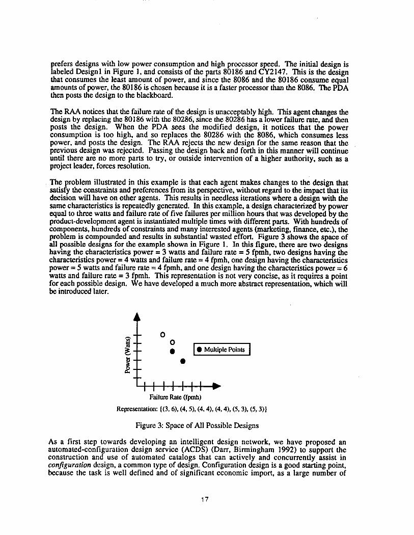
¯The problem illustrated in this example is that each agent makes changes to the design thatsatisfy the constraints and preferences from its perspective, without regard to the impact that itsdecision will have on other agents. This results in needless iterations where a design with thesame characteristics is repeatedly generated. In this example, a design characterized by powerequal to three watts and failure rate of five failures per million hours that was developed by theproduct-development agent is instantiated multiple times with different parts. With hundreds ofcomponents, hundreds of constraints and many interested agents (marketing, finance, etc.), theproblem is compounded and results in substantial wasted effort. Figure 3 shows the space ofall possible designs for the example shown in Figure 1. In this figure, there are two designshaving the characteristics power = 3 watts and failure rate = 5 fpmh, two designs having thecharacteristics power = 4 watts and failure rate = 4 fpmh, one design having the characteristicspower = 5 watts and failure rate = 4 fpmh, and one design having the characteristics power = 6watts and failure rate = 3 fpmh. This representation is not very concise, as it requires a pointfor each possible design. We have developed a much more abstract representation, which willbe introduced later.
OO¯ [¯ Multiple Points ]
IIIIlllIIIIIII
F~l~ ~te (fp~)
Re~e~nmtion: {(3, 6), O, 5), O, 4), ~, 4), (5, 3),
Figure 3: Space of All Possible Designs
As a first step towards developing an intelligent design network, we have proposed anautomated-configuration design service (ACDS) (Darr, Birmingham 1992) to support construction and use of automated catalogs that can actively and concurrently assist inconfiguration design, a common type of design. Configuration design is a good starting point,because the task is well defined and of significant economic import, as a large number of
17

artifacts are developed from catalogs of components (Mittal, Frayman 1987). Catalogs may based on current paper catalogs, or on parameterized models of currently uncataloged partfamilies. In time, we will include geometric features of custom parts, with their associatedfunctions and manufacturing processes.
In this paper, we present two methods for implementing ACDS. The first uses negotiationamong network agents to develop the design. This negotiation is based on eliminating constraintviolations. The second approach, called Walras (Wellman 1992), uses microeconomicprinciples of market action to create a design. Both approaches provide similar services,however, the Walrus has been only recently implemented. Thus, detailed comparison betweenapproaches is not yet possible because Walras has not yet been applied to concurrent design (orimplemented in the ACDS framework).
2. The Service
ACDS is a collection of loosely-coupled, autonomous agents that self-organize based on designspecifications. The agents coordinate their activities through a bidding process, eventuallychoosing a final (set of) design(s). This section overviews the organization and operation ACDS.
ACDS will provide the following services to users:
1. A language allowing users (or service companies acting for the users) to constructprecise, standardized descriptions of their products’ full range of characteristics.With this capability, site-specific catalogs can be developed that represent theparticular components used by an individual company or engineering group withina company. To protect proprietary information, access to agents can be controlled.
2. An associated language allowing system designers to precisely and quickly specifythe meehatronic systems they desire.
3. Algorithms operating on these descriptions to select near-optimal parts from thecatalogs, and to efficiently propagate selection decisions and constraints amongcatalog agents.
2.1 Inputs and Outputs
Design specifications comprise the following:
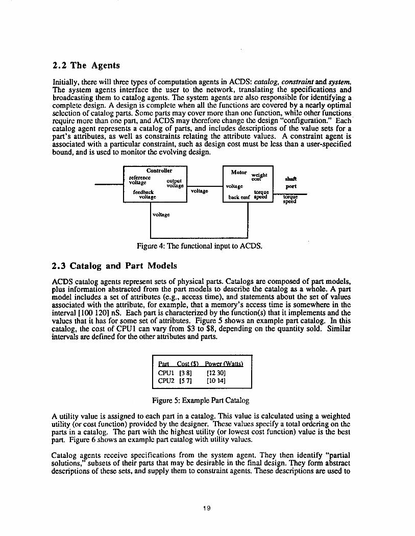
Functions and interconnection: The designer def’mes functions through a schematic withgeneric parts, and their logical and/or physical interconnections. In Figure 4 thefunctions are motor and controller. Ports, defined in a data dictionary, establishrelationships among selected part attributes.
Feasibility statements: These describe the set of values associated with design attributes(e.g., power, volume, etc.).
Preference statements: These describe characteristics the user would like the system tohave. An example is "pay $1 for every pound of weight saved", and prefer lowerweight designs to more reliable ones.
2.2 The Agents
Initially, there will three types of computation agents in ACDS: catalog, constraint and system.The system agents interface the user to the network, translating the specifications andbroadcasting them to catalog agents. The system agents are also responsible for identifying acomplete design. A design is complete when all the functions are covered by a nearly optimalselection of catalog parts. Some parts may cover more than one function, while other functionsrequire more than one part, and ACDS may therefore change the design "’configuration." Eachcatalog agent represents a catalog of parts, and includes descriptions of the value sets for apart’s attributes, as well as constraints relating the attribute values. A constraint agent isassociated with a particular constraint, such as design cost must be less than a user-specifiedbound, and is used to monitor the evolving design.
Controllerreferencevoltage output
vollagefeedback
voltagevoltage
Motor Wo~ght
voltage
back emf ~p~e
shaftport
torquespeea
voltage
Figure 4: The functional input to ACDS.
2.3 Catalog and Part Models
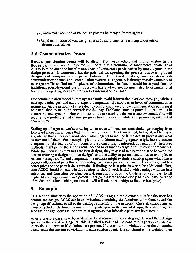
ACDS catalog agents represent sets of physical parts. Catalogs are composed of part models,plus information abstracted from the part models to describe the catalog as a whole. A partmodel includes a set of attributes (e.g., access time), and statements about the set of valuesassociated with the attribute, for example, that a memory’s access time is somewhere in theinterval [ 100 120] nS. Each part is characterized by the function(s) that it implements and thevalues that it has for some set of attributes. Figure 5 shows an example part catalog. In thiscatalog, the cost of CPU1 can vary from $3 to $8, depending on the quantity sold. Similarintervals are defined for the other attributes and parts.
Part Cost ($) Power (Watts)
CPUI [3 8] [12 30lCPU2 [5 7] [I0 14]
Figure 5: Example Part Catalog
A utility value is assigned to each part in a catalog. This value is calculated using a weightedutility (or cost function) provided by the designer. These values specify a total ordering on theparts in a catalog. The part with the highest utility (or lowest cost function) value is the bestpart. Figure 6 shows an example part catalog with utility values.
Catalog agents receive specifications from the system agent. They then identify "partialsolutions," subsets of their parts that may be desirable in the final design. They form abstractdescriptions of these sets, and supply them to constraint agents. These descriptions are used to
19

eliminate additional infeasible solutions in a form of network-consistency enforcement (Davis1987; Mackworth 1977). When feasibility pruning is no longer effective, catalog agents bid anew solution subspace. A bid is formed by selecting a subset of the parts in a catalog, andmaking this subset the catalog agent’s "current catalog". By forming bids based on preferencesand information received from constraint agents, ACDS agents narrow the design space, whileallowing all agents to process messages concurrently. This process continues until a final designresults. An example of this narrowing process is given later.
Utility Function = 2/Cost + l/Power
Part Cost ($) Power (Watts) UtilityCPU1 [3 8] [12 301 [0.283 0.750]CPU2 [5 71 [10 141 [0.357 0.500l
Figure 6: Example Part Catalog With Utilities
ACDS is intended to eventually support thousands of catalog agents distributed throughout theworld, where each agent will represent the product line of a manufacturer. As such, catalogagents have the freedom to choose whether to participate in a design, so the catalog agents willchange from design to design.
2.4 Constraints
ACDS constraint agents maintain consistency throughout the network by enforcing designconstraints. The constraints are formed over part attributes (e.g., the sum of powerconsumption of all parts < 15 W). Each constraint agent ensures that the evolving design spaceconforms to the constraint it represents. A constraint agent monitors the bids produced by eachcatalog agent, and provides information to the catalog agent regarding the violation status of theconstraint. This information is used by the catalog agents to form new bids.
An important element of concurrent engineering is considering downstream concerns (e.g.,dependability, testability, manufacturability, and so forth) during the design process. Constraintagents can represent such concerns, and thus impact the design process as it occurs. Forexample, a constraint agent can monitor the failure rate (one measure of dependability), andcause designs with unacceptable rates to be eliminated.
ACDS constraints are linear, additive, non-directional, and can be of any arity. Non-directionality means that if a constraint is defined over n variables C(xl, .... Xn), then given n-1variables, the ith variable can be inferred: xi - c’l(xl, .... xi-1, xi+l ..... Xn).
Constraints originate from two sources. Non-part specific constraints, which are static, comefrom the system agent. An example of this type of constraint is total power consumption:~powereonsumed<6Watts. Part-specific constraints, which are dynamic (Mittal,Falkenhainer 1987), come from catalog agents, since the system agent does not know whichcatalog agents will participate in the design. An example of this type of constraint is the accesstime for some CPU: access time = 2*clock speed - memory-access time.
A dynamic constraint has a predicate indicating when it is active. The value of the predicate for astatic constraint is always true. Dynamic constraints can be made active or inactive during thedesign process, depending on the parts that are currently being considered. When inactive, a
20

constraint is not evaluated. This is useful when parts have different properties. For example,different types of CPUs have different constraints for memory-access time. Only those partsthat are used to form a bid have their dynamic constraints activated.
In ACDS, all static constraints are created by the system agent when the network is established.Dynamic constraints are created by the catalog agents that contain them. When a catalog agentaccepts an invitation to participate in a design it creates separate processes for each of itsdynamic constraints, thereby distributing the computational load.
2.5 Set-based Descriptions
We are interested in creating mechatronic (highly integrated mechanical and electrical systems).Because these systems are composed of radically different types of components, representationis a major concern. We have developed a representation scheme, called Labeled-IntervalCalculus or LIC (Ward, Lozano-Perez, Seering 1990), that captures the operating characteristicsof both mechanical and electrical devices. The LIC distinguishes between the statement that amotor is restricted to speeds ONLY between 0 to 1800 RPM, and the statement that it will undernormal operating conditions take EVERY speed in that interval. With this representation we canapply the same design algorithms regardless of the components involved.
Instead of reasoning over single points in the set of all possible designs, ACDS reasons overdesign spaces, which are sets of points in the space of all possible designs. The ACDS designspace is represented as a set of intervals, where each interval corresponds to a design attribute(Davis 1987; Ward, Lozano-Perez, Seering 1990). Each interval specifies the possible range values for some attribute for all designs in the design space. Each catalog agent defines itsdesign space as a set of intervals lbr each attribute in its catalog. Each constraint agent definesits design space as the set of intervals provided by catalogs having attributes that appear in itsconstraint. Figure 7 shows the design space representation for the example in Figure 1. In thisrepresentation, the set of all possible designs has been replaced by a set of intervals thatrepresents the region within which all possible designs must lie.
Nm
ttllltlIIIIlll
l~lure~lle(~mh)
Re~e~nmtion: {13 51, [3 6])
Figure 7: Design-Space Representation
The design space representation provides three advantages over current schemes:
1) Precise descriptions of a broad range of mechanical and electronic components,providing the basis for a degree of standardization not now possible.
21
2) Concurrent execution of the design process by many different agents.
3) Rapid exploration of vast design spaces by simultaneous reasoning about sets ofdesign possibilities.
2.6 Communication Issues
Because participating agents will be distant from each other, and might number in thethousands, communication resources will be held at a premium. A fundamental challenge inACDS is to balance the benefits and costs of concurrent participation by many agents in thedesign process. Concurrency has the potential for speeding the process, discovering noveldesigns, and being resilient to partial failures in the network. It does, however, strain bothcommunication channels and computation resources as agents sift through massive amounts ofmessage traffic to find useful pieces of information. In fact, it could be argued that thetraditional point-by-point design approach has evolved not so much due to organizationalbarriers among designers as to problems of information overload.
Our communication model is that agents should avoid information overload through judiciousmessage exchanges, and should expend computational resources in favor of communicationresources. As the network changes due to component choices, new communication paths mustbe established to maintain network consistency. Problems, such as potential circularities inconstraints and synchronizing component bids to search the design space systematically, willrequire new protocols that ensure progress toward a design while still promoting substantialconcurrency.
Scaling up to larger networks covering wider areas will pose research challenges ranging fromlow-level encoding schemes that minimize numbers of bits transmitted, to high-level heuristicknowledge that guides decisions about which agents to include in the design process and whatto demand of them. For example, given that different catalog agents might have commoncomponents (the brands of components they carry might intersect, for example), heuristicmethods might prune the set of agents needed to ensure coverage of all relevant components.While such heuristics may miss the best designs, they may lead to a better balance between thecost of creating a design and that design’s end-use utility or performance. As an example, toreduce message traffic and computation, a network might exclude a catalog agent which has apoorer collection of parts than other catalog agents (its parts are subsumed by another), but hasbetter prices on the parts it does contain. If finding the best price is worth the additional effort,then ACDS should not exclude this catalog, or should work initially with catalogs with the bestselection, and then after deciding on a design should open the bidding for each part to allapplicable catalogs (much like a person might go to a large car dealership to investigate the rangeof models, and after deciding on a model will call other dealerships to find the best price).
3. Example
This section illustrates the operation of ACDS using a simple example. After the user hasentered the design, ACDS sends an invitation, containing the functions to implement and thedesign specifications, to all of the catalogs currently on the network. Once all catalog agentshave accepted or declined the invitation to participate in the current design, the catalog agentssend their design spaces to the constraint agents so that infeasible parts can be removed.
After infeasible parts have been identified and removed, the catalog agents send their designspaces to the constraint agents (this is called a bid) and the constraint agents evaluate theintervals to determine if violations are present. If a constraint is violated, then the constraintagent sends the amount of violation to each catalog agent. If a constraint is not violated, then
22

the constraint agent sends the amount that the constraint is satisfied by (called slack), to each its participating catalog agents.
When the catalog agents receive the amount of violation or slack from each of the constraintagents, then the catalog agents create new design spaces that reduce the amount of violation onthe intervals for the violated constraints, without exceeding the slack on the intervals for thesatisfied constraints. The catalog agents bid their new design spaces and the process continuesuntil all constraints are satisfied, at which point each catalog agent sends its the highest ratedpart as a solution, or until a determination is made that no solution exists. No solution exists ifnone of the catalog agents can create a new design space.
For this example, the user specifies that the design should implement the functions CPU,memory and serial port, that the cost of the final design be less than or equal to $11.001, andthat the failure rate be less than or equal to 10 failures per million hours (fpmh). The costfunction for this example is a simple weighted sum of the attributes, where the weight of thecost attribute is 10 and the weight of the failure-rate attribute is 1. Using a cost function of thisform, a part with a low value for cost function is preferable to a part with a high value for costfunction. The catalog agents CPU, memory and serial port respond, indicating that they arewilling to participate in the design. The system agent creates the constraint agents cost andfailure rate. If there were any dynamic constraints, then the catalog agents would create theseconstraints at this time. At this point, the network consists of the catalog agents {CPU,memory, serial port} and the constraint agents {cost, failure rate}. Each catalog agent creates adesign space by forming an interval over each of the design attributes. The initial ACDSnetwork, including the design spaces for each catalog, is shown in Figure 8.
Part Name cost failure rate cost functionMemoryl 6.0 2.0 62.0Memory2 3.0 3.0 33.0Memory3 2.0 6.0 26.0Memory4 2.0 4.0 24.0Memory5 1.0 7.0 17.0
Ce12.I~.figa.Sl/a~cost -- [ 1.0 6.0]failure rate = [1.0 7.0]cost function = [15.0 61.0]
Part Name cost failure rote cost functionCPU 1 6.0 1.0 61.0CPU2 4.0 7.0 47.0CPU3 2.0 2.0 22.0CPU4 1.0 5.0 15.0
Memory Design Spacgcost = [1.0 6.0]failure rate = [2.0 7.0]cost function = [17.0 62.0]
Serial Port Design Snacecost = [1.0 6.0]failure rate = [1.0 8.0]
serial port cost function = [16.0 61.0]
Part Namecost failure rate cost functionSerial Portl 6.0 1.0 61.0Serial Port2 3.0 3.0 33.0Serial Port3 2.0 4.0 24.0Serial Port4 1.0 8.0 18.0Serial Port5 1.0 6.0 16.0
Figure 8: Initial ACDS Network
1 If the lower bound on an attribute is omitted, then it is assumed tO be 0. Similarly, if the upper bound on an
attribute is omitted, then it is assumed to be + o~.
23

The system agent next notifies each catalog agent of the appropriate constraint agents and viceversa. The system agent does this by sending the address and the name of each constraint agentto each catalog agent. If a catalog agent contains parts that have values for attributes appearing inthe constraint represented by a constraint agent, then the address of the constraint agent isrecorded in the local address table of the catalog agent, who then sends a message to the systemagent indicating that the constraint agent needs to know the address of the catalog agent. Thesystem agent then sends the address of the catalog agent to the constraint agent. In this way, thecatalog agents know only the addresses of constraint agents that it must communicate with, andvice versa.
3.1 Pruning Infeasibles
After the design spaces are created, the CPU, memory and serial port catalog agents send theintervals to the cost and failure-rate constraint agents.
The cost and failure-rate constraint agents collect the intervals from the catalog agents, formingthe design spaces cost = {[1.0 6.0] (from CPU), [1.0, 6.0] (from memory), [1.0 6.0] (fromserial port)] and failure rate = {[1.0 7.0] (from CPU), [2.0 7.0] (from memory), [1.0 (from serial port)}. These design spaces are used to form arc-consistent intervals. The arc-consistent intervals for the failure-rate constraint agent is calculated as shown in Figure 9.
failure rate = [2.0 7.0]
failure rate<ffi 10.0memory: [2.0 7.0]CPU: [I.0 7.0]serial port: [1.0 7.0]
failure rate = [1.0 7.01 failure rate = [1.0 8.0]
Figure 9: Arc-Consistent Design Spaces
The interval [ 1.0 7.0] for the failure-rate attribute of the serial port catalog agent is calculated asfollows: the minimum value for the failure-rate attribute that can be achieved by the memory andCPU catalog agents are 2.0 and 1.0 fpmh, respectively. In order for the constraint to besatisfied, the maximum value possible for the serial port catalog agent must be no greater than.I0.0 - (2.0 + 1.0) = 7.0. This value becomes the upper bound for the serial port catalog agentfor the failure rate interval.
The constraint agents send these arc-consistent intervals to each catalog agent, who remove anyinfeasible parts (i.e., parts that lie outside the arc-consistent intervals), forming new designspaces. Figure 10 shows the new catalogs. This operation can be used to eliminate the 80286 inthe example at the beginning of the paper. This would eliminate many of the iterationsdescribed, at virtually no cost.
24

3.2 Design-Space Bidding
Once all infeasible parts have been removed, each catalog bids its design space to the constraintagents for evaluation. The constraint agents collect the intervals from all the catalog agents, anddetermine whether or not a constraint has been violated.
Part Name cost failure rate cost functionMemoryl 6.0 2.0 62.0Memory2 3.0 3.0 33.0Memory3 2.0 6.0 26.0Memory4 2.0 4.0 24.0Memory5 1.0 7.0 17.0
cost = [I.0 6.0]failure rate = [1.0 7.0]cost function = [15.0 61.0]
Part Name cost failure rate cost functionCPUI 6.0 1.0 61.0CPU2 4.0 7.0 47.0CPU3 2.0 2.0 22.0CPU4 1.0 5.0 15.0
AC Memory_ Intervalscost = [1.0 6.0]failure rate = [2.0 7.0]cost function = [17.0 62.0]
AC Serial Port Intervals
cost -- [1.0 6.0]failure rate = [1.0 7.0]
serial port cost function = [16.0 61.0]
Part Name cost failure rate cost function
Serial Portl 6.0 1.0 61.0Serial Port2. 3.0 3.0 33.0Serial Port3 2.0 4.0 24.0£c-r2 Pc.-’.~. !.~ o.~ io.~Serial Port5 1.0 6.0 16.0
Figure 10: Arc Consistent Catalogs.
In this example, the constraint agents create a design space of the form:
[ ~ catalog agent interval lower bound ~ catalog agent interval upper bound]catalog agents catalog agents
A constraint agent is satisfied if every value contained in the interval satisfies the constraint.Once the violations are determined, a message is sent to each catalog agent, containing theamount of violation if the constraint is violated, or the amount of slack if the constraint issatisfied. This step is illustrated in Figure 11. For example, if the maximum values of eachintervals contributing to cost are added, the upper bound is violated (the sum is 18.0). Thus thecost interval for some catalog agent must be reduced.
3.3 Design-Space Pruning
Since there are constraint violations, each catalog agent must modify its catalog in such a way asto satisfy the violated constraints. A new design space is formed by removing parts or re-introducing parts that were previously removed.
Since each constraint agent is violated, each catalog simply removes the part with the highestvalue for each of the attributes, as is shown in Figure 12. This results in the catalogs consistingof the set of parts surrounded by boxes. The old and new design spaces are shown alongsidethe corresponding catalog agents.
25
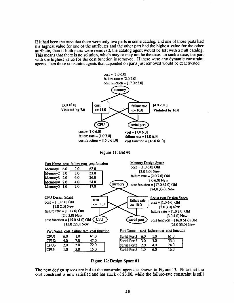
If it had been the case that there were only two parts in some catalog, and one of those parts hadthe highest value for one of the attributes and the other part had the highest value for the otherattribute, then if both parts were removed, the catalog agent would be left with a null catalog.This means that there is no solution, which may or may not be the case. In such a case, the partwith the highest value for the cost function is removed. If there were any dynamic constraintagents, then those constraint agents that depended on parts just removed would be deactivated.
cost = [ 1.0 6.01failure rate = [2.0 7.0]cost function = [17.0 62.0]
[3.0 18.0]Violated by 7.0
cost = [1.0 6.0]failure rate = [1.0 7.01cost function = [15.0 61.0]
[4.0 20.0]Violated by 10.0
s~ port
cost = [1.0 6.01failure rate = [1.0 6.0]cost function = [16.0 61.0]
Figure 11: Bid #1
Part Name cost failure rate cost function
Memoryl 6.0 2.0 62.0
IMemory2 3.0 3.0 33.0Memory3 2.0 6.0 26.0Memory4 2.0 4.0 24.0Memory5 1.0 7.0 17.0
Memory_ Design Spacecost = [1.0 6.0] Old
[2.0 3.0] Newfailure rate = [2.0 7.0] Old
[3.0 6.0] Newcost function = [17.0 62.0] Old
[24.0 33.0] New
cost = [1.0 6.0] Old[1.0 2.0] New
failure rate = [1.0 7.0] Old[2.0 5.01 New
cost function = [15.0 61.0] Old[ 15.0 22.0] New
Part Name cost failure rate cost function
CPUI 6.0 1.0 61.0CPU2 4.0 7.0 47.0
ICPU3 2.0 2.0 22.0ICPU4 1.0 5.0 15.0
serial port
Part Name
Serial Portl
Serial Port Desi_t,n Spacecost = [1.0 6.0] Old
[2.0 3.0] Newfailure rate = [1.0 7.0] Old
[3.0 4.0] Newcost function = [16.0 61.0] Old
[24.0 33.0] New
cost failure rate cost function
6.0 1.0 61.0
ISerial Port?. 3.0 3.0 33.0
[Serial Port3 2.0 4.0 24.0Serial Port5 1.0 6.0 16.0
Figure 12: Design Space #1
The new design spaces are bid to the constraint agents as shown in Figure 13. Note that thecost constraint is now satisfied and has slack of $3.00, while the failure-rate constraint is still
26
violated.
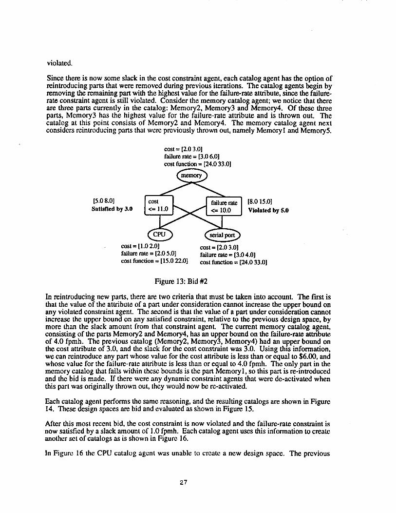
Since there is now some slack in the cost constraint agent, each catalog agent has the option ofreintroducing parts that were removed during previous iterations. The catalog agents begin byremoving the remaining part with the highest value for the failure-rate attribute, since the failure-rate constraint agent is still violated. Consider the memory catalog agent; we notice that thereare three parts currently in the catalog: Memory2, Memory3 and Memory4. Of these threeparts, Memory3 has the highest value for the failure-rate attribute and is thrown out. Thecatalog at this point consists of Memory2 and Memory4. The memory catalog agent nextconsiders reintroducing parts that were previously thrown out, namely Memoryl and Memory5.
cost = [2.0 3.0]failure rate = [3.0 6.0]cost function = [24.0 33.0]
[5.0 8.0]Satisfied by 3.0
cost = [1.0 2.0]failure rate = [2.0 5.0]cost function = [15.0 22.0]
[8.0 15.0]Violated by 5.0
serial port
cost = [2.0 3.0]failure rate = [3.0 4.0]cost function = [24.0 33.0]
Figure 13: Bid #2
In reintroducing new parts, there are two criteria that must be taken into account. The first isthat the value of the attribute of a part under consideration cannot increase the upper bound onany violated constraint agent. The second is that the value of a part under consideration cannotincrease the upper bound on any satisfied constraint, relative to the previous design space, bymore than the slack amount from that constraint agent. The current memory catalog agent,consisting of the parts Memory2 and Memory4, has an upper bound on the failure-rate attributeof 4.0 fpmh. The previous catalog (Memory2, Memory3, Memory4) had an upper bound the cost attribute of 3.0, and the slack for the cost constraint was 3.0. Using this information,we can reintroduce any part whose value for the cost attribute is less than or equal to $6.00, andwhose value for the failure-rate attribute is less than or equal to 4.0 fpmh. The only part in thememory catalog that falls within these bounds is the part Memoryl, so this part is re-introducedand the bid is made. If there were any dynamic constraint agents that were de-activated whenthis part was originally thrown out, they would now be re-activated.
Each catalog agent performs the same reasoning, and the resulting catalogs are shown in Figure14. These design spaces are bid and evaluated as shown in Figure 15.
After this most recent bid, the cost constraint is now violated and the failure-rate constraint isnow satisfied by a slack amount of 1.0 fpmh. Each catalog agent uses this information to createanother set of catalogs as is shown in Figure 16.
In Figure 16 the CPU catalog agent was unable to create a new design space. The previous
27
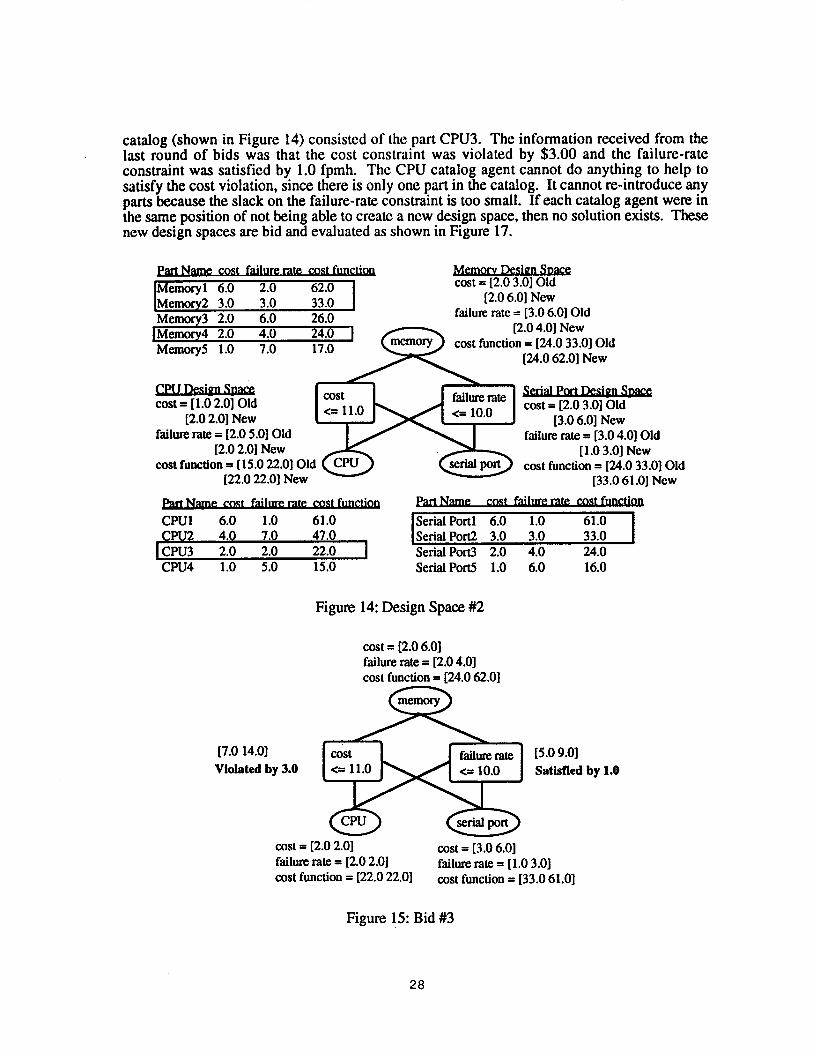
catalog (shown in Figure 14) consisted of the part CPU3. The information received from thelast round of bids was that the cost constraint was violated by $3.00 and the failure-rateconstraint was satisfied by 1.0 fpmh. The CPU catalog agent cannot do anything to help tosatisfy the cost violation, since there is only one part in the catalog. It cannot re-introduce anyparts because the slack on the failure-rate constraint is too small. If each catalog agent were inthe same position of not being able to create a new design space, then no solution exists. Thesenew design spaces are bid and evaluated as shown in Figure 17.
Part Name cost failure rate cost function Memory Design Space
IMemoryl6.0 2.0 62.0 cost = [2.0 3.0] Old
Memory2 3.0 3.0 33.0 [2.0 6.0] New
Memory3 2.0 6.0 26.0 failure rate = [3.0 6.0] Old
]Memory4 2.0 4.0 24.0 I [2.0 4.0] New
Memory5 1.0 7.0 17.0 cost function = [24.0 33.0] Old[24.0 62.0] New
cost -- [1.0 2.0] Old[2.0 2.0] New
failure rate = [2.0 5.0] Old[2.0 2.0] New
cost function = [15.0 22.0] Old[22.0 22.0] New
Part Name cost failure rate cost function
CPUI 6.0 1.0 61.0CPI.I2 4.0 7.0 47.0IcptJ3 20 2.0 220 ICPU4 1.0 5.0 15.0
serial port
Part Name
Serial Port Design Soacecost -- [2.0 3.0] Old
[3.0 6.0] Newfailure rate = [3.0 4.0] Old
[1.0 3.0] Newcost function = [24.0 33.0] Old
[33.0 61.0] New
cost failure rate cost function
ISerial Portl 6.0 1.0Serial Port2 3.0 3.0
61.0 I33.0
Serial Port3 2.0 4.0Serial Port5 1.0 6.0
24.016.0
Figure 14: Design Space #2
cost = [2.0 6.0]failure rate = [2.0 4.0]cost function = [24.0 62.0]
[7.0 14.0]Violated by 3.0
cost = [2.0 2.01failure rate = [2.0 2.01cost function = [22.0 22.0]
[5.0 9.0]Satisfied by 1.0
serial port
cost = [3.0 6.01failure rate = [I.0 3.0]cost function = [33.0 61.0]
Figure 15: Bid #3
28

3.4 Solution
Once all the constraints are satisfied, as they are in Figure 17, the catalog agents select theremaining part with the lowest value for the cost function to form a solution. Because allconstraints are satisfied, the combination of these parts is guaranteed to be a valid solution. Inthis example, the CPU catalog agent selects the part CPU3, the memory catalog agent selects thepart Memory4 and the serial port catalog agent selects the part Serial Port3. The designconsisting of these parts satisfy all constraints and is sent to the system agent as the solution.The system agent verifies that all functions have been covered and displays the solution. This isshown in Figure 18.
Part Name cost failure rate cost function
Memo~l 6.0 2.0 62.0IMemory2 3.0 3.0 33.0 IMemory3 2.0 6.0 26.0
[Memory4 2.0 4.0 24.0 [Memory5 1.0 7.0 17.0
Memory_ Design Spacecost = [2.0 6.0] Old
[2.0 3.0] Newfailure rate = [2.0 4.0] Old
[3.0 4.0] Newcost function = [24.0 62.0] Old
[24.0 33.0] New
cost = [1.0 2.0] Old[2.0 2.0] New
failure rate --- [2.0 5.0] Old[2.0 2.0] New
cost function = [15.0 22.0] Old[22.0 22.0] New
Part Name cost failure rate cost functionCPUI 6.0 1.0 61.0CPU2 4.0 7.0 47.0
Icpu3 20 20 220 ICPU4 1.0 5.0 15.0
serial port
Part Name
Serial Portl
Serial Port Design Spacecost = [3.0 6.0] Old
[2.0 3.0] Newfailure rate = [1.0 3.0] Old
[3.0 4.0] Newcost function = [33.061.0] Old
[24.0 33.0] Newcost failure rate cost function
6.0 1.0 61.0Serial Port2 3.0 3.0 33.0
ISerial Port3 2.0 4.0 24.0Serial Port5 1.0 6.0 16.0
Figure 16: Design Space #3
4. A Market-Oriented Programming Approach
Another approach to distributed design that we are concurrently exploring is the potential use ofmarket price mechanisms to allocate resources among collaborating design teams. The rationalefor this approach is that in some circumstances, the market can efficiently allocate resourcestoward their most productive use with minimal communication or coordination overhead. Allinteraction among agents occurs via exchange of goods, according to terms dictated by a set ofstandard prices.
We have implemented a general system for "market-oriented programming" based on conceptsfrom the microeconomic theory of general equilibrium. In the general-equilibrium framework,there are two types of agents: those that simply exchange goods (consumers), and those that cantransform some goods into other goods (producers). In our computational version of a marketprice system, we implement consumer and producer agents and direct them to bid so as tomaximize utility or profits, subject to their own feasibility constraints. Under certain technicalassumptions, the equilibria of this system correspond to desirable or optimal resourceallocations.
29
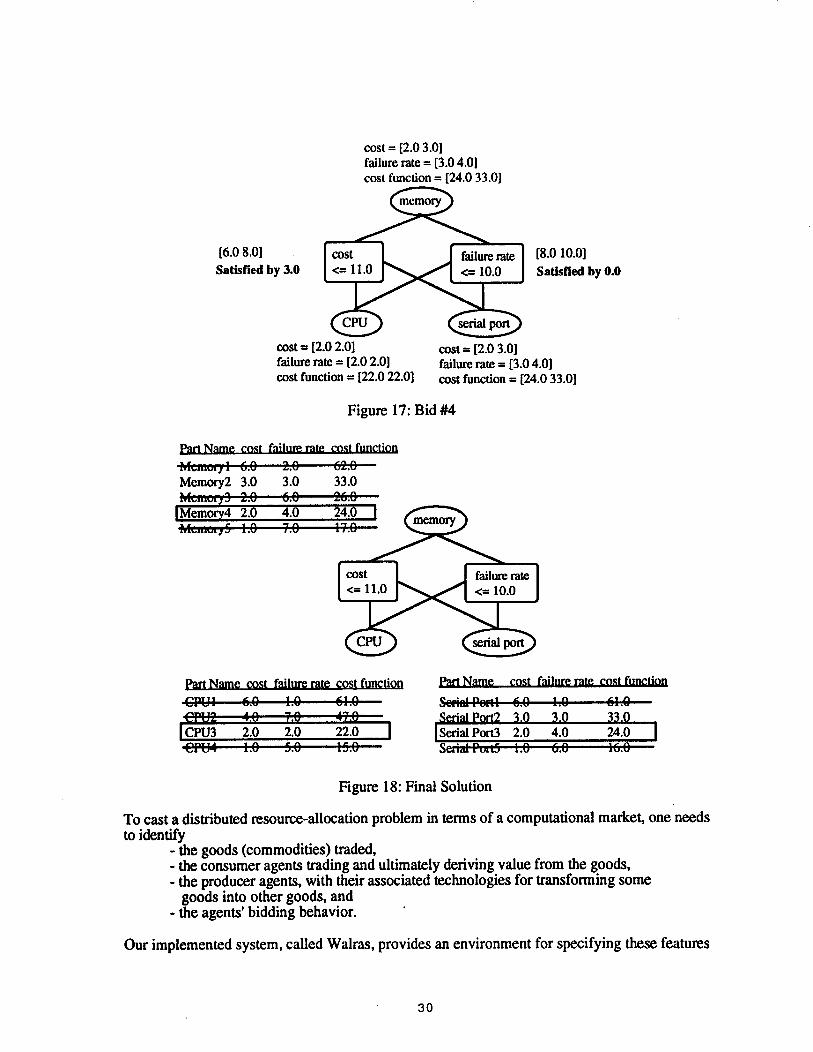
cost = [2.0 3.0]failure rate --- [3.0 4.0]cost function = [24.0 33.0]
[6.0 8.0]Satisfied by 3.0
[8.0 I0.0]Satisfied by 0.0
cost = [2.0 2.01failure rate = [2.0 2.0]cost function -- [22.0 22.0]
cost = [2.0 3.0]failure rate = [3.0 4.0]cost function = [24.0 33.0]
Figure 17: Bid #4
Part Name cost failure rate cost function
Memory2 3.0 3.0 33.0M,,,;,¢,;: 3 2.0 6.,7, 2(,.~IMemory4 2.0 4.0 24.0 [}.’.,; ~5 I~ .....¯ £,GJ . , .v ¯ e .,a
serial port
Part Name cost failure rate cost function
~:’U: 4,e 7,~ -:7.~Icpu3 2.0 2.0 22.0 I
Part Name cost failure rate cost function
Serial Port2 3.0 3.0 33.0ISerialporO 2.0 4.0 24.0 I
Figure 18: Final Solution
To cast a distributed resource-allocation problem in terms of a computational market, one needsto identify
- the goods (commodities) traded,- the consumer agents trading and ultimately deriving value from the goods,
the producer agents, with their associated technologies for transforming somegoods into other goods, and
- the agents’ bidding behavior.
Our implemented system, called Walras, provides an environment for specifying these features
30

of a computational market.
Given the specification, Walras "runs" the economy to derive its competitive equilibrium, thatis, a set of prices for the goods where (1) consumers bid so to maximize utility, subject to theirbudget constraints, (2) producers bid so to maximize profits, subject to their technologicalpossibilities, and (3) net demand is zero for all goods. Details of Walras’s bidding process andunderlying assumptions are provided elsewhere (Wellman 1992).
Distributed configuration design is one of the tasks to which we have applied Walras. In amultiagent design problem, each agent has responsibility for choosing a component to serve agiven function in a device, and the overall design consists of the combination of componentchoices. Decentralizing the problem can be difficult, due to dependencies in the componentchoices for each function, as well as interactions among the components in determining deviceperformance attributes, or preferences for those attributes.
For example, consider a simple two-component device consisting of a motor and a speedcontroller. We are interested in a device with the best performance (highest torque with finesttolerance on the speed range) but that minimizes some other attributes (weight, powerconsumption, and dollar cost). There may be several choices for each component, whichcombine via cross product to define the overall design space. Choices for the componentsinteract, because the horsepower ratings for the motor and speed controller must be compatible,and because both components contribute to weight and dollar cost.
The market perspective on this kind of problem would view the performance and resourceattributes as commodities traded and transformed across the components. In some approaches todistributed design (including human design organizations), some aggregate attributes arebudgeted in a hierarchical manner, so that the part implementing a given function may beallocated some fixed fraction of the weight or dollar cost. This kind of scheme is too rigid,because we do not know what the appropriate fractions should be until we make some progressin the design. This is where the market approach should help. If attributes such as weight aretradable commodities, then the components can buy and sell rights to take up weight accordingto which can make the most effective use (i.e., get the most relative performance improvement)from each incremental unit of weight.
To cast one of these problems in Walras, we first define a consumer agent to represent the end-user of the device we are designing. We specify for this consumer a utility function defined overpossible combinations of all of the attributes. The consumer also has an endowment of the basicresources (weight, dollar cost, power) corresponding to the maximum feasible that can allocated to the device. This endowment limit performs the same function as the constraint agentin ACDS.
For each component (ACDS catalog agent), we define a producer agent. The producer agenttransforms the basic resources into performance attributes (torque, voltage)according to thespecifications of each possible choice for the component. In other words, the catalog describesthe technology available to the corresponding producer.
The consumer’s problem is to set demands maximizing utility, subject to the budget constraint(i.e., it cannot spend more than the value of its endowment), at the going prices. The producersface a discrete choice among the possible component instances, each providing a series ofvalues for resource and performance attributes. The producer bids according to which choicewould be most profitable at the given set of prices. If none offers positive profits, the producerbids zero.

When run on some simple design problems, Walras produces a set of component choices.However, due to the discreteness (and other non-convexities) of the problem, the overall designis not guaranteed to be optimal. At best, we can hope for local optima. In current work, we areattempting to characterize the performance of the scheme for special cases. In addition, we arelooking into hybrid schemes that use the market to bound the optimal value by computing theglobal optimum for a smooth and convex relaxation of the original problem. This is analogousto branch-and-bound schemes that make use of regular linear-programming algorithms forinteger-programming problems.
5. Discussion
We have chosen a distributed architecture for several reasons. Design expertise for a complexartifact is usually distributed across different groups and may be geographically dispersedwithin a single company or in multiple companies. Centrally locating all relevant expertise, inmost cases, is awkward at best. A distributed architecture naturally models the real-worlddistribution of expertise. This distribution of knowledge also speeds computation, subject tocommunication costs, by sharing the computation load across many different computers. Withthe advent of high-speed communication networks, communication cost will constantly fall.
A distributed architecture provides the user of ACDS with easy access to a wide variety of partcatalogs from many different vendors, without being aware of who or where those vendors are.The only concern of the designer should be that the parts selected satisfy the specifications. Byconsidering parts from a variety of sources, ACDS has the opportunity to generate the bestpossible design.
A distributed architecture also allows each vendor to maintain its catalog agent at its site.Changes or additions to the part catalogs can be made locally and be immediately available to allusers over the network. ACDS allows vendors to join the network without knowing who orwhere the designers using the network are located. This allows a new vendor to become knownto a large population of designers, and be on an equal competitive footing with more establishedvendors.
ACDS will allow designers to realize their designs in significantly shorter time than is currentlypossible using today’s concurrent design processes. Furthermore, designs will be less costlyand of higher quality since ACDS can consider a much greater variety of designs than anyhuman could effectively create.
ACDS will allow descriptions of many part characteristics, such as the behavior of mechanicaldevices, that cannot properly be described using current languages. This will allow automationof many manual design processes.
ACDS will provide a uniform representation for a wide range of types of data important to thedesign process, including marketing and finance information, as well as engineering data. Thiswill make agent inter-operability an inherent property of the service, and will significantlycontribute to enterprise integration.
ACDS relies on several concepts from the distributed artificial intelligence literature. ACDSdraws from multistage negotiation (Conry, Kuwabara, Lesser, Meyer 1991), distributedconstraint-satisfaction problems (Yokoo, Durfee, Ishida, Kuwabara 1991), and negotiatedsearch (Lander, Lesser 1992). Negotiated search is a cooperative search and conflict resolutionparadigm realized by TEAM, a system for performing parametric design of steam condensers.Each TEAM agent possesses knowledge about a single steam condenser component. Theseagents are independent, except for parameters that are shared among components. TEAM agents
32
communicate via shared memory. In this system, an initial design is generated and placed inshared memory so that all agents can evaluate it. Each agent examines the design and proposesextensions to the design that solve some sub-problem. The catalog and constraint agents ofACDS are collapsed into one agent in TEAM. Like ACDS, agents in TEAM share a globalutility (or cost) function to help guide decision-making.
Other systems that operate in the domain of concurrent engineering and are similar to ACDSinclude the Design-Fabricator Interpreter (DFI) system (Werkman 1992), and the Galileo2system (Bowen, Bahler 1992b). The DFI system is an example of the point-by-point approachto concurrent engineering in the domain of structural engineering. In this system, agents thatrepresent human experts in the areas of design, manufacturing and assembly evaluate andcomment on a design from their particular perspective. Much like ACDS, this system supportsconcurrent engineering by incorporating downstream concerns early in the design process,using agents to represent multiple perspectives. The DFI system is more of a design evaluationtool used to critique a preliminary design to identify possible downstream problems. The DFIsystem can be thought of as automating the stage at which a higher authority is required toresolve a conflict, where each agent proposes an acceptable design, and an arbitrator makes adecision.
The Galileo2 system is a constraint programming language that facilitates concurrentengineering. This system allows constraint networks to be divided into different, possiblyoverlapping fields of view that correspond to the perspectives of engineering teams. Byassigning fields of view to manufacturability, testability, maintainability, and others, this systemsupports concurrent engineering. Galileo2 is an interactive system which allows a user tospecify constraints on the final design from a given perspective. Galileo2 is not a synthesis toollike ACDS, but is rather a design evaluation tool. Galileo2 makes it easier for designers tocommunicate, but the process of resolving conflicts still requires manual intervention. BothACDS and Galileo2 use constraints to represent various design perspectives, but differ in theway these constraints are used. In Galileo2, constraints are used to form a constraint network,where constraints are propagated throughout the network to notify users that a constraint hasbeen violated. In ACDS, constraints are used to rule out parts that are provably infeasible.
6. Current Status
A prototype version of ACDS has been developed that contains core ACDS functionality in arudimentary form. This version was used to create the example in Section 3, and allows systemagents to establish contact with catalog agents distributed anywhere in the nation. Currently,ACDS has agents operating in Ann Arbor, Michigan (The University of Michigan), Pittsburgh,Pennsylvania (Carnegie Mellon University), and Palo Alto, CA (Stanford University).Similarly, constraint agents can be distributed throughout a network.
We are beginning to expand the capabilities of ACDS. A mechanical-drawing system andseveral analysis packages (e.g., thermal and reliability) are being integrated into ACDS. Thiswill allow designers to create custom designs that are synthesized from catalog components, andto analyze these designs from a variety of perspectives that are not easily captured in constraints.This will be a major step in moving ACDS towards the goal of supporting all aspects of design.
ACDS has been developed to be fully compatible with KQML (Finin et al. 1992), a languagefor knowledge exchange among intelligent agents. (KQML is being supported by DARPA’sKnowledge-Sharing Effort.) This compatibility means that ACDS can conveniently exchangeknowledge with agents developed by other parties, and can easily integrate into existingengineering networks.
33

Walras is being integrated into the full ACDS environment. We expect to report soon oncomparisons between the approaches.
ReferencesBowen J., Bahler D.(1992a), "A Constraint-Based Approach to Networked Collocation
Concurrent Engineering", Proceedings First Workshop on Enabling Technologies forConcurrent Engineering.
Bowen J, Bahler D.(1992b), "Supporting Multiple Perspectives: A constraint-based approachto concurrent engineering", Proceedings of Artificial Intelligence in Design.
Conry S., Kuwabara K., Lesser V., Meyer R.(1991), "Multistage Negotiation for DistributedConstraint Satisfaction", IEEE Transactions on Systems, Man, and Cybernetics,21:1462-1477.
Dan"T. P., Birmingham W. P. (1992), "Concurrent Engineering: An Automated Design SpaceApproach", Tech Report CSE-TR-149-92, University of Michigan, Ann Arbor, MI.
Davis E. (1987), "Constraint Propagation with Interval Labels", Artificial Intelligence 32:281-331.
Durfee E., Lesser V., Corkill D. (1989), "Trends in Cooperative Distributed Problem Solving",IEEE Transactions on Knowledge and Data Engineering, 1:63-83.
FininT., et al. (1992), "Specification of the KQML Agent-Communication Language", Tech.Report E1T TR 92-04, Enterprise Integration Technologies, Palo Alto, CA.
Lander S., Lesser, V.(1992), "Negotiated Search: Cooperative Search Among HeterogeneousExpert Agents", AAAI Workshop on Cooperation Among Heterogeneous IntelligentSystems.
Mackworth A. K. (1977), "Consistency in Networks of Relations", Artificial Intelligence 8:99-118.
Mittal S., Falkenhainer B. (1990), "Dynamic Constraint Satisfaction Problems", Proc. AAAI.Mittal S., Frayman F. (1987), "COSSACK: A Constraint-Based Expert System for
Configuration Tasks", Proc. 2nd Int’l Conf. on Applications of Al to Engineering.Pan J., Tenenbaum J. (1991), "An Intelligent Agent Framework for Enterprise Integration",
IEEE Transactions on Systems, Man and Cybernetics, November/December 1991.Ward A., Lozono-Perez T., Seering W.(1990), "Extending the Constraint Propagation
Intervals", AI EDAM 4:47-54.Ward A., Seering W. (1989), "Quantitative Inference in a Mechanical Design ’Compiler’",
ASME Design Theory and Methodology Conference.Wellman M. (1992), "A general-equilibrium approach to distributed transportation planning",
Proc. AAAI.Werkman K. J. (1992), "Multiple Agent Cooperative Design Evaluation Using Negotiation",
Proceedings of Arn’ficial Intelligence in Design.Yokoo M., Durfee E., Ishida T., Kuwabara K.(1991), "Distributed Constraint Satisfaction for
Formalizing Distributed Problem Solving", Dept. of EECS, University of MichiganTechnical Report No. CSE-TR-102-91 1991.
34