Mechatronic Design Process REV III - Philadelphia …. Mechatronic... · Mechatronic Design Process...
53
DR. TAREK A. TUTUNJI PHILADELPHIA UNIVERSITY, JORDAN 2014 Mechatronic Design Process REV III
Transcript of Mechatronic Design Process REV III - Philadelphia …. Mechatronic... · Mechatronic Design Process...
D R . T A R E K A . T U T U N J I
P H I L A D E L P H I A U N I V E R S I T Y , J O R D A N
2 0 1 4
Mechatronic Design Process REV III

Mechatronics: Synergetic Integration of Different Disciplines
[Ref.] Prof. Rolf Isermann

Mechanical and Information Processing
[Ref.] Prof. Rolf Isermann
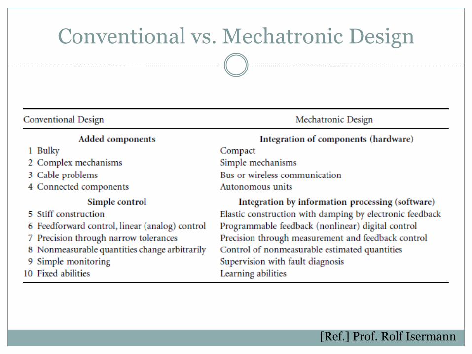
Conventional vs. Mechatronic Design
[Ref.] Prof. Rolf Isermann

Mechatronic System Integration
[Ref.] Prof. Rolf Isermann

Multi-Level Control Architecture
Level 1 low level control (feedforward, feedback for damping,
stabilization, linearization)
Level 2 high level control (advanced feedback control strategies)
Level 3 supervision, including fault diagnosis
Level 4 optimization, coordination (of processes)
Level 5 general process management
[Ref.] Prof. Rolf Isermann

[Ref.] Prof. Rolf Isermann

Mathematical Models
Mathematical process models for static and dynamic behavior are required for various steps in the design of mechatronic systems, such as simulation, control design, and reconstruction of variables.
There are two ways to obtain these models:
Theoretical modeling based on first (physical) principles
Experimental modeling (identification) with measured input and output variables
[Ref.] Prof. Rolf Isermann

Simulation Methods
[Ref.] Prof. Rolf Isermann

Real-Time Simulation
[Ref.] Prof. Rolf Isermann

Hardware-In-the-Loop (HIL)
The hardware-in-the-loop simulation (HIL) is characterized by operating real components in connection with real-time simulated components.
Usually, the control system hardware and software is the real system, as used for series production. The controlled process (consisting of actuators, physical processes, and sensors) can either comprise simulated components or real components,

PC-Based Hardware-in-the-Loop Simulation
Control Prototyping
For the design and testing of complex control systems and their algorithms under real-time constraints, a real-time controller simulation (emulation) with hardware (e.g., off-the-shelf signal processor) other than the final series production hardware (e.g., special ASICS) may be performed.
The process, the actuators, and sensors can then be real. This is called control prototyping

Real-Time Simulation
[Ref.] Prof. Rolf Isermann

Integrated Design Issues
Concurrent engineering of the mechatronics approach relies heavily on the use of system modeling and simulation throughout the design and prototyping stages.
It is especially important that it be programmed in a visually intuitive environment.
block diagrams, flow charts, state transition diagrams, and bond graphs.

Integrated Design Issues
Mechatronics is a design philosophy: an integrating approach to engineering design.
Mechatronics makes the combination of actuators, sensors, control systems, and computers in the design process possible.
Starting with basic design and progressing through the manufacturing phase, mechatronic design optimizes the parameters at each phase to produce a quality product in a short-cycle time

Modeling vs. Experimental Validation
[Ref.] Craig and Stolfi

Hardware and Software Integration
[Ref.] Prof. Divdas Shetty
Concurrent Engineering
Concurrent engineering is a design approach in which the design and manufacture of a product are merged in a special way. It is necessary that the knowledge and necessary information be
coordinated amongst different expert groups.
The characteristics of concurrent engineering are Better definition of the product without late changes.
Design for manufacturing and assembly undertaken in the early design stage.
Process on how the product development is well defined.
Better cost estimates.
Decrease in the barriers between design and manufacturing.

Concurrent Engineering
[Ref.] Bradley

Mechatronic System Design (MSD)
Design is an engineering philosophy that can vary between different schools of thought.
MSD should follow a well-defined iterative design steps that incorporate synergetic design. It should include the following operations: 1. User and system requirements analysis
2. Conceptual Design
3. Mechanical, software, electronics, and interface design
4. System modeling and simulation
5. Prototyping and testing

Mechatronic System Block Diagram

Design Stages
• Stage 1: Define the Objective and Specifications
• Stage 2: Analyze and Design
• Stage 3: Build and Test

Stage 1: Define the Objectives & Specifications
1. Identify the problem.
2. Research and literature review
3. Set the initial system specifications.

Design Stage 2: Analyze and Design
4. Establish a general block diagram and a flow chart
Specify system I/O
Specify control algorithm to use
5. Choose appropriate components
Sensors and actuators; Controller
Drive and signal conditioning circuits
6. Concurrent/Synergistic Design
Mechanical structure; Electronic system; Software/controller; Interface
7. Model and simulate the system

Stage 3: Build and Test
8. Emulate the controller hardware
9. Build prototype, test, and evaluate (modify if needed)

Synergistic Design

Mechatronic Design Process
[Ref.] Prof. Divdas Shetty

V-Model MSD from Association of German Engineers Guidelines, VDI 2206

Computer-Aided Systems: Important Features
Modeling: Block diagrams for working with understandable multi-disciplinary
models that represent a physical phenomenon.
Simulation: Numerical methods for solving models containing differential, discrete,
linear, and nonlinear equations.
Project Management: Database for maintaining project information and subsystem models for eventual reuse.
Design: Numerical methods for constrained optimization of performance
functions based on model parameters and signals.

Computer-Aided Systems: Important Features
Analysis: Frequency-domain and time-domain tools
Real-Time Interface: A plug-in card is used to replace part of the model with actual hardware
by interfacing to it with actuators and sensors.
Code Generator: Produces efficient high-level source code (such as C/C++) from the block
diagram. The control code will be compiled and used on the embedded processor.
Embedded Processor Interface: Communication between the process and the computer-aided
prototyping environment.

Mechatronic Key Elements
Information Systems
Modeling and Simulation
Optimization
Mechanical Systems
Electrical Systems
DC and AC Analysis
Power
Sensors and actuators
Real-Time Interfacing

Information Systems
Information systems include all aspects for information exchange
Signal processing, control systems, and analysis techniques
The following are essential for mechatronics applications
Modeling and Simulation
Automatic control
Numerical methods for optimization.

Information Systems: Modeling
Modeling is the process of representing the behavior of a real system by a collection of mathematical equations and logic.
Models can be static or dynamic Static models produce no motion, heat transfer, fluid flow, traveling
waves, or any other changes.
Dynamic models have energy transfer which results in power flow. This causes motion, heat transfer, and other phenomena that change in time.
Models are cause-and-effect structures—they accept external information and process it with their logic and equations to produce one or more outputs. Parameter is a fixed-value unit of information
Signal is a changing-unit of information
Models can be text-based programming or block diagrams

Information Systems: Simulation
Simulation is the process of solving the model and is performed on a computer.
Simulation process can be divided into three sections:
Initialization
Iteration,
Termination.

Mechanical Systems
Mechanical systems are concerned with the behavior of matter under the action of forces.
Such systems are categorized as rigid, deformable, or fluid in nature. Rigid-bodies assume all bodies and connections in the system to be
perfectly rigid. (i.e. do not deform)
Fluid mechanics consists of compressible and incompressible fluids.
Newtonian mechanics provides the basis for most mechanical systems and consists of three independent and absolute concepts: Space, Time, and Mass.
Force, is also present but is not independent of the other three

Electrical Systems
Electrical systems are concerned with the behavior of three fundamental quantities: Charge, current, and voltage
Electrical systems consist of two categories: Power systems and Communication systems
An electric circuit is a closed network of paths through which current flows.
Circuit analysis is the process of calculating all voltages and
currents in a circuit given as is based on two fundamental laws : Kirchhoff ’s current law: The sum of all currents entering a node is zero. Kirchhoff ’s voltage law: The sum of all voltage drops around a closed loop is
zero.

Electrical Systems: Power
Energy is the capacity to do work various
Potential, kinetic, electrical, heat, chemical, nuclear, and radiant.
Power is the rate of energy transfer, and in the SI unit system, the unit of energy is the joule and the unit of power is the watt (1 watt 1 joule per second).

Sensors
Sensors are required to monitor the performance of machines and processes
Common variables in mechatronic systems are temperature, speed,
position, force, torque, and acceleration. Important characteristics: the dynamics of the sensor, stability, resolution,
precision, robustness, size, and signal processing.
Intelligent sensors are available that not only sense information but process it well Progress in semiconductor manufacturing technology has made it possible to
integrate sensor and the signal processing on one chip Sensors are able to ascertain conditions instantaneously and accurately These sensors facilitate operations normally performed by the control algorithm,
which include automatic noise filtering, linearization sensitivity, and self-calibration.
Actuators
Actuation involves a physical action on a machine or process. They can transform electrical inputs into mechanical outputs such as force, angle, and position.
Actuators can be classified into three general groups. 1. Electromagnetic actuators, (e.g., AC and DC electrical
motors, stepper motors, electromagnets)
2. Fluid power actuators, (e.g., hydraulics, pneumatics)
3. Unconventional actuators (e.g., piezoelectric, magnetostrictive, memory metal)

Real-Time Interfacing
Real-time interface provides data acquisition and control functions for the computer.
Reconstruct a sensor waveform as a digital sequence and
make it available to the computer software for processing. The control function produces an analog approximation as a
series of small steps. Real-time interfacing includes:
A/D and D/A conversions Analog signal conditioning circuits Sampling theory.

MECHATRONIC APPLICATIONS

Automotive Industry
Vehicle diagnostics and monitoring. Sensors to detect the environment; monitor engine coolant, temperature and quality; Engine oil pressure, level, and quality; tire pressure; brake pressure.
Pressure, temperature sensing in various engine and power locations; exhaust gas
analysis and control; Crankshaft positioning; Fuel pump pressure and fuel injection control; Transmission force and pressure control.
Airbag safety deployment system. Micro-accelerometers and inertia sensors
mounted on the chassis of the car measures car deceleration in x or y directions can assist in airbag deployment.
Antilock brake system, cruise control. Position sensors to facilitate antilock braking
system; Displacement and position sensors in suspension systems. Seat control for comfort and convenience. Displacement sensors and micro
actuators for seat control; Sensors for air quality, temperature and humidity, Sensors for defogging of windshields.

Robots

Aerospace Industry
Landing gear systems; Cockpit instrumentation; Pressure sensors for oil, fuel, transmission; Air speed monitor; Altitude determination and control systems.
Fuel efficiency and safety systems; Propulsion control with pressure sensors; Chemical leak detectors; Thermal monitoring and control systems.
Inertial guidance systems; Accelerometers; Fiber-optic gyroscopes for guidance and monitoring.
Automatic guided vehicles, space application; Use of
automated navigation system for NASA projects; Use of automated systems in under water monitoring and control

Consumer Products

Consumer Industry
Consumer products such as auto focus camera, video, and CD players; Consumer electronic products such as washing machines and dish washers.
Video game entertainment systems; Virtual instrumentation in home entertainment.
Home support systems; Garage door opener; Sensors with heating, ventilation, and air-conditioning system; Home security systems.

Production Machines

Industrial Systems and Products
Monitoring and control of the manufacturing process; CNC machine tools; Advanced high speed machining and quality monitoring.
Rapid prototyping; Manufacturing cost saving by rapid creation of models done by CAD/CAM integration and rapid prototyping equipment.
Specialized manufacturing process such as the use of welding robots; Procedure for automatically programming and controlling a robot from CAD data.

3D Printing

Health Care Industry
Medical diagnostic systems, non-invasive probes such as ultrasonic probe. Disposable blood pressure transducer;
Pressure sensors in several diagnostic probes. Systems to control the intravenous fluids and drug flow;
Endoscopic and orthopedic surgery. Angioplasty pressure sensor; Respirators; Lung capacity meters.
Other products such as Kidney dialysis equipment; MRI equipment.

Mechatronic System Example: DC Motor
[Ref.] Prof. Divdas Shetty

Conclusion
Mechatronics design can lead to high quality and cost effective products Traditional sequential manner do not possess optimum design
capabilities.
Concurrent design results in the development of intelligent and flexible mechatronic system
Increasing demands on the productivity of machine tools and their growing technological complexity call for improved methods in future product development processes.