
Super Tilematic G2 Operator’s manual Manual de ...€¦ · Operators Manual, Super Tilematic G2,...
20
Operators Manual, Super Tilematic G2, 2005-04, 542 20 10-38 542 20 10-38 Super Tilematic G2 STM 10100 G2 STM 10100SS G2 Operator’s manual Read these instructions carefully and make sure you understand them before using the TARGET Tilematic G2. Manual de Instrucciones Antes de utilizar TARGET Tilematic G2 lea bien el manual de instrucciones hasta comprender su contendo. Manuel d’utilisation Lire attentivement et bien assimiler le manuel d’utilisation avant de se servir TARGET Tilematic G2.
Transcript of Super Tilematic G2 Operator’s manual Manual de ...€¦ · Operators Manual, Super Tilematic G2,...
1
Operators Manual, Super Tilematic G2, 2005-04, 542 20 10-38
542 20 10-38
Super Tilematic G2
STM 10100 G2STM 10100SS G2
Operator’s manualRead these instructions carefully andmake sure you understand them beforeusing the TARGET Tilematic G2.
Manual deInstruccionesAntes de utilizar TARGET Tilematic G2lea bien el manual de instruccioneshasta comprender su contendo.
Manuel d’utilisationLire attentivement et bien assimiler lemanuel d’utilisation avant de se servirTARGET Tilematic G2.

2
EVERY MACHINE IS THOROUGHLY TESTED BEFORE LEAVING THE FACTORY. EACH MACHINE IS SUPPLIEDWITH A COPY OF THIS MANUAL. OPERATORS OF THIS EQUIPMENT MUST READ AND BE FAMILIAR WITHTHE SAFETY WARNINGS. FAILURE TO OBEY WARNINGS MAY RESULT IN INJURY OR DEATH. FOLLOWINSTRUCTIONS STRICTLY TO ENSURE LONG SERVICE IN NORMAL OPERATION.
CONTENTSSymbol Definitions ................................................................................................................................................. 3 - 5Hearing Hazard Warning ............................................................................................................................................ 5Decal Descriptions and Locations ......................................................................................................................... 6 - 7Safety Warnings - DOs & DO NOTs...................................................................................................................... 8 - 9
Figures:Figure 1 .................................................................................................................................................................... 10Figure 2 .................................................................................................................................................................... 13Figure 3 .................................................................................................................................................................... 14Figure 4 .................................................................................................................................................................... 15
Instructions:1. Features .......................................................................................................................................................... 112. Benefits ............................................................................................................................................................ 113. Machine Set-Up ........................................................................................................................................11 - 134. Operating Procedure ...................................................................................................................................... 135. Adjustable Lockbar With Depth Linking Protection ......................................................................................... 136. Manual Thermal Overload .............................................................................................................................. 147. Recommended Extension Cords .................................................................................................................... 148. Alignment Procedures .................................................................................................................................... 149. Profile Wheel Set-Up and Use ................................................................................................................. 14 - 1510. Plunge Cutting ................................................................................................................................................ 1511. Maintenance Procedures ................................................................................................................................ 1512. Water Pump, Trouble Shooting Procedure ..................................................................................................... 1513. Repairs ........................................................................................................................................................... 1514. Spare Parts ..................................................................................................................................................... 1515. Tile Cutting Accessories ................................................................................................................................. 16
Wiring Diagrams ............................................................................................................................................... 17 - 18Warranty ................................................................................................................................................................... 19
NOTE:Part Numbers that have an ASTERISK (*) suffix may not be active 9-digit numbers.The '542' prefix have been added to current 6-digit part numbers and '0' to 8-digitpart numbers.

3
Symbol DefinitionsSymbolesDefinición De Los Simbolos
• Please read the instructions for use prior to operating the machine for the first time.• Avant toute mise en service, lire attentivement la notice et se familiariser avec la machine.• Antes de la puesta en marcha, lea detenidamente las instrucciones y familiaricese con la máquina.
• Mandatory• Obligatoire• Obligatorio
• Indication• Indicazione• Indicación
• Prohibition• Interdiction• Prohibición
• Warning Triangle• Triangle d’advertissement• Triángwulo De Advertencia
• Wear Eye Protection• Port obligatoire des lunettes de protection• Usar Gafas De Protección
• Wear Head Protection• Port Obligatoire Du Casque Et Des Écouteurs• Usar Casco De Protección
• Wear Breathing Protection• Port obligatoire d’un masque respiratoire protecteur• Usar Máscara De Protección
• The Use Of Ear Protection Is Mandatory• Port obligatoire da casque antibruit• Es Obligatorio El Uso De Protección Auditiva
• Wear a Hard Hat• Port Obligatoire Da Casque Antibruit• Usar Casco Duro
• Wear Safety Shoes• Port obligatoire des chaussures de sécurité• Usar Zapatos De Seguridad
• Wear Appropriate Clothing• Port obligatoire de la tenue appropriée• Usar Ropa Adecuada
• Remove The Blade Prior To Hoisting, Loading, Unloading And Transporting The Machine On Jobsite.• Démontage Obligatoire Du Disque En Cas D’élingage, De Chargement, De Déchargement Et
DeTransport Sur Le Chantier.• Desmontar El Disco Antes De Desplazar, Cargar, Descargar O Transportar La Máquina En La Obra.
4
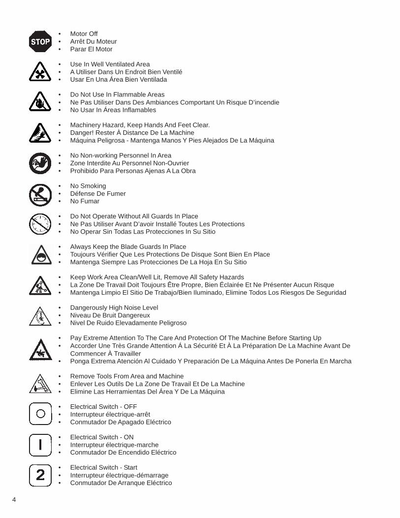
• Motor Off• Arrêt Du Moteur• Parar El Motor
• Use In Well Ventilated Area• A Utiliser Dans Un Endroit Bien Ventilé• Usar En Una Área Bien Ventilada
• Do Not Use In Flammable Areas• Ne Pas Utiliser Dans Des Ambiances Comportant Un Risque D’incendie• No Usar In Áreas Inflamables
• Machinery Hazard, Keep Hands And Feet Clear.• Danger! Rester À Distance De La Machine• Máquina Peligrosa - Mantenga Manos Y Pies Alejados De La Máquina
• No Non-working Personnel In Area• Zone Interdite Au Personnel Non-Ouvrier• Prohibido Para Personas Ajenas A La Obra
• No Smoking• Défense De Fumer• No Fumar
• Do Not Operate Without All Guards In Place• Ne Pas Utiliser Avant D’avoir Installé Toutes Les Protections• No Operar Sin Todas Las Protecciones In Su Sitio
• Always Keep the Blade Guards In Place• Toujours Vérifier Que Les Protections De Disque Sont Bien En Place• Mantenga Siempre Las Protecciones De La Hoja En Su Sitio
• Keep Work Area Clean/Well Lit, Remove All Safety Hazards• La Zone De Travail Doit Toujours Être Propre, Bien Éclairée Et Ne Présenter Aucun Risque• Mantenga Limpio El Sitio De Trabajo/Bien Iluminado, Elimine Todos Los Riesgos De Seguridad
• Dangerously High Noise Level• Niveau De Bruit Dangereux• Nivel De Ruido Elevadamente Peligroso
• Pay Extreme Attention To The Care And Protection Of The Machine Before Starting Up• Accorder Une Très Grande Attention Á La Sécurité Et À La Préparation De La Machine Avant De
Commencer À Travailler• Ponga Extrema Atención Al Cuidado Y Preparación De La Máquina Antes De Ponerla En Marcha
• Remove Tools From Area and Machine• Enlever Les Outils De La Zone De Travail Et De La Machine• Elimine Las Herramientas Del Área Y De La Máquina
• Electrical Switch - OFF• Interrupteur électrique-arrêt• Conmutador De Apagado Eléctrico
• Electrical Switch - ON• Interrupteur électrique-marche• Conmutador De Encendido Eléctrico
• Electrical Switch - Start• Interrupteur électrique-démarrage• Conmutador De Arranque Eléctrico
5
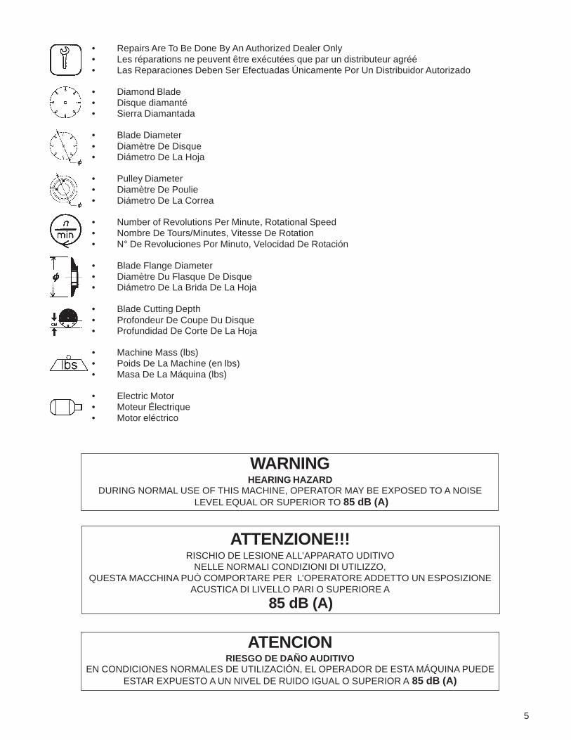
WARNINGHEARING HAZARD
DURING NORMAL USE OF THIS MACHINE, OPERATOR MAY BE EXPOSED TO A NOISE LEVEL EQUAL OR SUPERIOR TO 85 dB (A)
ATTENZIONE!!!RISCHIO DE LESIONE ALL’APPARATO UDITIVO
NELLE NORMALI CONDIZIONI DI UTILIZZO,QUESTA MACCHINA PUÒ COMPORTARE PER L’OPERATORE ADDETTO UN ESPOSIZIONE
ACUSTICA DI LIVELLO PARI O SUPERIORE A
85 dB (A)
ATENCIONRIESGO DE DAÑO AUDITIVO
EN CONDICIONES NORMALES DE UTILIZACIÓN, EL OPERADOR DE ESTA MÁQUINA PUEDEESTAR EXPUESTO A UN NIVEL DE RUIDO IGUAL O SUPERIOR A 85 dB (A)
• Repairs Are To Be Done By An Authorized Dealer Only• Les réparations ne peuvent être exécutées que par un distributeur agréé• Las Reparaciones Deben Ser Efectuadas Únicamente Por Un Distribuidor Autorizado
• Diamond Blade• Disque diamanté• Sierra Diamantada
• Blade Diameter• Diamètre De Disque• Diámetro De La Hoja
• Pulley Diameter• Diamètre De Poulie• Diámetro De La Correa
• Number of Revolutions Per Minute, Rotational Speed• Nombre De Tours/Minutes, Vitesse De Rotation• N° De Revoluciones Por Minuto, Velocidad De Rotación
• Blade Flange Diameter• Diamètre Du Flasque De Disque• Diámetro De La Brida De La Hoja
• Blade Cutting Depth• Profondeur De Coupe Du Disque• Profundidad De Corte De La Hoja
• Machine Mass (lbs)• Poids De La Machine (en lbs)• Masa De La Máquina (lbs)
• Electric Motor• Moteur Électrique• Motor eléctrico

6
DECAL DESCRIPTIONS & LOCATION
P/N 542 18 70-43*Location: Top of Belt Guard
P/N 542 04 63-26*Location: Motor Assembly
P/N 542 04 63-27*Location: Motor Assembly
P/N 542 18 92-47*Location: Elec. Motor

7
DECAL DESCRIPTIONS & LOCATION
P/N 542 18 97-36*Location: Front of Pan
P/N 542 18 97-31*Location: Blade Guard & Belt Guard
P/N 542 18 76-91*Location: Belt Guard Top
P/N 542 20 30-64Location: Both Sides of Pan
8
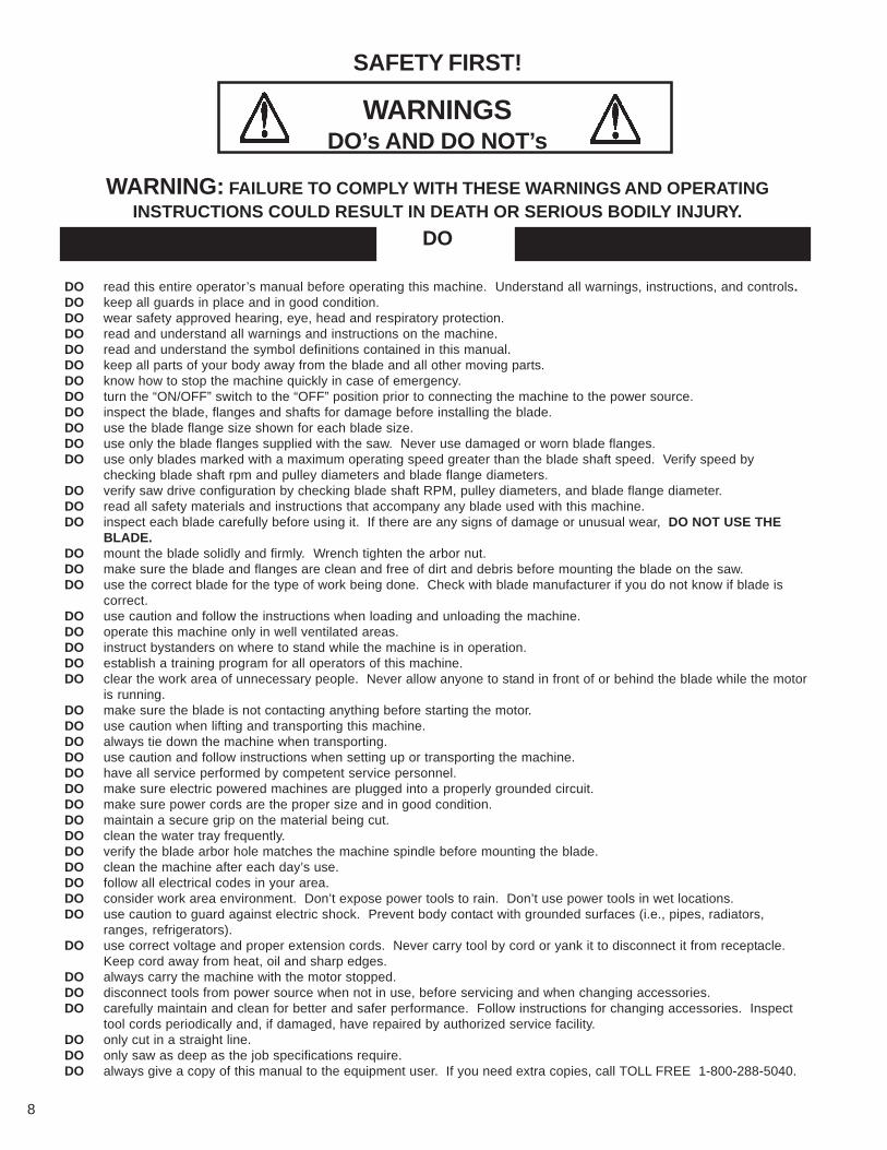
DO read this entire operator’s manual before operating this machine. Understand all warnings, instructions, and controls.DO keep all guards in place and in good condition.DO wear safety approved hearing, eye, head and respiratory protection.DO read and understand all warnings and instructions on the machine.DO read and understand the symbol definitions contained in this manual.DO keep all parts of your body away from the blade and all other moving parts.DO know how to stop the machine quickly in case of emergency.DO turn the “ON/OFF” switch to the “OFF” position prior to connecting the machine to the power source.DO inspect the blade, flanges and shafts for damage before installing the blade.DO use the blade flange size shown for each blade size.DO use only the blade flanges supplied with the saw. Never use damaged or worn blade flanges.DO use only blades marked with a maximum operating speed greater than the blade shaft speed. Verify speed by
checking blade shaft rpm and pulley diameters and blade flange diameters.DO verify saw drive configuration by checking blade shaft RPM, pulley diameters, and blade flange diameter.DO read all safety materials and instructions that accompany any blade used with this machine.DO inspect each blade carefully before using it. If there are any signs of damage or unusual wear, DO NOT USE THE
BLADE.DO mount the blade solidly and firmly. Wrench tighten the arbor nut.DO make sure the blade and flanges are clean and free of dirt and debris before mounting the blade on the saw.DO use the correct blade for the type of work being done. Check with blade manufacturer if you do not know if blade is
correct.DO use caution and follow the instructions when loading and unloading the machine.DO operate this machine only in well ventilated areas.DO instruct bystanders on where to stand while the machine is in operation.DO establish a training program for all operators of this machine.DO clear the work area of unnecessary people. Never allow anyone to stand in front of or behind the blade while the motor
is running.DO make sure the blade is not contacting anything before starting the motor.DO use caution when lifting and transporting this machine.DO always tie down the machine when transporting.DO use caution and follow instructions when setting up or transporting the machine.DO have all service performed by competent service personnel.DO make sure electric powered machines are plugged into a properly grounded circuit.DO make sure power cords are the proper size and in good condition.DO maintain a secure grip on the material being cut.DO clean the water tray frequently.DO verify the blade arbor hole matches the machine spindle before mounting the blade.DO clean the machine after each day’s use.DO follow all electrical codes in your area.DO consider work area environment. Don’t expose power tools to rain. Don’t use power tools in wet locations.DO use caution to guard against electric shock. Prevent body contact with grounded surfaces (i.e., pipes, radiators,
ranges, refrigerators).DO use correct voltage and proper extension cords. Never carry tool by cord or yank it to disconnect it from receptacle.
Keep cord away from heat, oil and sharp edges.DO always carry the machine with the motor stopped.DO disconnect tools from power source when not in use, before servicing and when changing accessories.DO carefully maintain and clean for better and safer performance. Follow instructions for changing accessories. Inspect
tool cords periodically and, if damaged, have repaired by authorized service facility.DO only cut in a straight line.DO only saw as deep as the job specifications require.DO always give a copy of this manual to the equipment user. If you need extra copies, call TOLL FREE 1-800-288-5040.
SAFETY FIRST!
WARNINGSDO’s AND DO NOT’s
WARNING: FAILURE TO COMPLY WITH THESE WARNINGS AND OPERATINGINSTRUCTIONS COULD RESULT IN DEATH OR SERIOUS BODILY INJURY.
DO

9
DO NOT operate this machine unless you have read and understood this operator’s manual.DO NOT operate this machine without the blade guard, or other protective guards in place.DO NOT stand behind or in front of the blade path while the motor is running.DO NOT leave this machine unattended while the motor is running.DO NOT operate this machine when you are tired or fatigued.DO NOT use a wet blade without adequate water supply to the blade.DO NOT exceed maximum blade speed shown for each blade size. Excessive speed could result in blade breakage.DO NOT operate the machine if you are uncertain of how to run the machine.DO NOT use damaged equipment or blades.DO NOT touch or try to stop a moving blade with your hand.DO NOT cock, jam, wedge or twist the blade in a cut.DO NOT transport a cutting machine with the blade mounted on the machine.DO NOT use a blade that has been dropped or damaged.DO NOT use carbide tipped blades.DO NOT use abrasive blades.DO NOT use conventional abrasive blades with water.DO NOT touch a dry cutting diamond blade immediately after use. These blades require several minutes to cool
after each cut.DO NOT use damaged or worn blade flanges.DO NOT allow other persons to be near the machine when starting or when the machine is in operation.DO NOT operate this machine in an enclosed area unless it is properly vented.DO NOT operate this machine in the vicinity of anything that is flammable. Sparks could cause a fire or an explo-
sion.DO NOT allow blade exposure from the guard to be more than 180 degrees.DO NOT operate this machine with the belt guard or blade guard removed.DO NOT operate this machine unless you are specifically trained to do so.DO NOT use a blade that has been over heated (Core has a bluish color).DO NOT jam material into the blade.DO NOT grind on the side of the blade.DO NOT lay power cords in or near the water.DO NOT replace the motor with any motor that does not have a special grounding connection.DO NOT cut deeper than 1" per pass with a dry blade. Step out to achieve deeper cuts.DO NOT start cutting with a saw until you have a clear work area and secure footing.DO NOT operate this machine while using drugs or alcohol.
*****************
This saw was designed for certain applications only. DO NOT modify this saw or use for any application otherthan for which is it was designed. If you have any questions relative to its application, DO NOT use the saw untilyou have written Electrolux Construction Products and we have advised you.
Electrolux Construction Products17400 West 119th Street
Olathe, Kansas 66061In USA 1-800-288-5040
SAFETY FIRST!
WARNINGSDO’s AND DO NOT’s
WARNING: FAILURE TO COMPLY WITH THESE WARNINGS AND OPERATINGINSTRUCTIONS COULD RESULT IN DEATH OR SERIOUS BODILY INJURY.
DO NOT
10
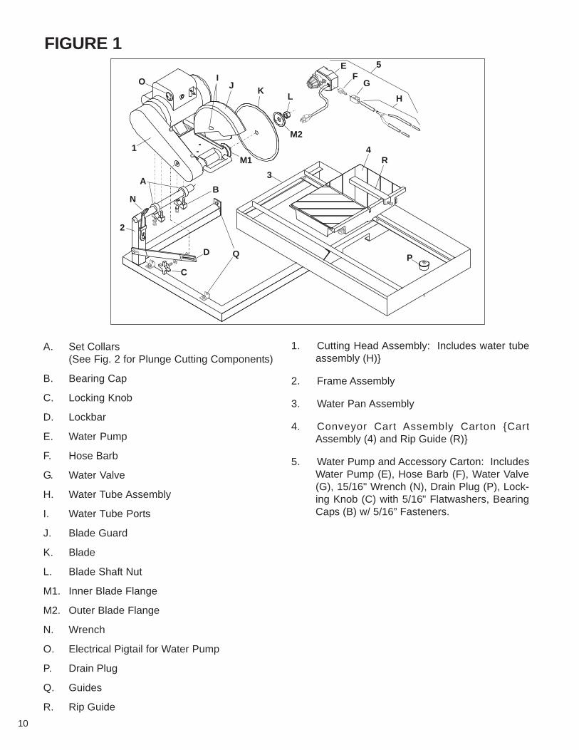
FIGURE 1
2
1
3
4R
5EF
G
H
N
AB
C
D Q
O IJ K
L
M2
M1
P
A. Set Collars(See Fig. 2 for Plunge Cutting Components)
B. Bearing Cap
C. Locking Knob
D. Lockbar
E. Water Pump
F. Hose Barb
G. Water Valve
H. Water Tube Assembly
I. Water Tube Ports
J. Blade Guard
K. Blade
L. Blade Shaft Nut
M1. Inner Blade Flange
M2. Outer Blade Flange
N. Wrench
O. Electrical Pigtail for Water Pump
P. Drain Plug
Q. Guides
R. Rip Guide
1. Cutting Head Assembly: Includes water tubeassembly (H)}
2. Frame Assembly
3. Water Pan Assembly
4. Conveyor Cart Assembly Carton {CartAssembly (4) and Rip Guide (R)}
5. Water Pump and Accessory Carton: IncludesWater Pump (E), Hose Barb (F), Water Valve(G), 15/16" Wrench (N), Drain Plug (P), Lock-ing Knob (C) with 5/16" Flatwashers, BearingCaps (B) w/ 5/16” Fasteners.
11
These signs will giveadvice for your safety
Before leaving our factory every machine is thoroughlytested.
Follow our instructions strictly and yourmachine will give you long service in normaloperating conditions.
MANDATORYI N S T R U C T I O NINDICATIONINFORMATION
WARNING PROHIBITION
Use: Sawing of any kind of tile, up to 31" (787mm).Diagonal on 22" x 22" (559 x 559mm) tile.
Tools: Rip Guide comes standard on all tile saws.See Tile Cutting Accessories on page 19.
(For information or availability of other accessoriescontact your Target supplier.)
Blade Capacity: Rim Ø 10" (254mm) - bore 5/8"(15,9mm).Profile Wheel: Rim Ø 6" (152mm) - bore 5/8"(15,9mm).Blade Rotation: Counter-Clockwise (CCW).Depth of Cut: 3-3/4" (95mm) with 10" (254mm) blade.
Horsepower: 1-1/2 1-1/2Voltage: 115 115/230Hertz: 60 60F.L. Amperages: 14.6 17.2/8.6
Blade Shaft RPM: 2760 3880Weight: lb. (kg.) 105 (48) 110 (50)Dimensions - L x W x H: in 51-1/4" x 26-7/16" x 22-5/4"
(mm) (1,302 x 671 x 575)
Conveyor Cart - L x W: in (mm) 16 x 16-1/2" (406 x 419)Pan Holding Capacity: 12 gallons (46.1 liters)Water Pump Output: 100 gal/hr. (378 l /hr.) Standard
300 gal/hr. (1135 i/hr.) Optional
The operator must wearprotective clothingappropriate to the work heis doing.
Any persons not involved in the work shouldleave the area.
See Figure 1
• Remove all items from the shipping carton andidentify:1. Cutting Head Assembly (1): Includes Water
Tube Assembly (H)2. Frame Assembly (2)3. Water Pan Assembly (3)4. Conveyor Cart Assembly {Cart Assembly (4) and
Rip Guide (R)}
• The new, improved blade guard offers simplified bladeinstallation and removal - maximum 10" (254mm)blade capacity. The external water tube assembly (H)is removable for easy maintenance.
•1-1/2 HP, High Torque (HT) 115V/60/1 motor onstandard saw.
• The dependable, high volume, submersible coolantpump features a screened intake.
• The motor and pump power cords are securelymounted directly into the Motor Housing (O).
• The removable Drain Plug (P) at the back end of thepan permits easy coolant draining and quick sludgeclean out. The Water Pan (3) is removable for easycleaning.
• The free-rolling Conveyor Cart (4) is aligned forstraight, smooth cuts. The Back Stop with ruler allowsfast mounting and adjustment of the Rip Fence (R)and optional accessories.
• Makes diagonal cuts on 22" x 22" (559 x 559 mm)tile. Can make 31” (787mm) rip cuts.
• Full-size belt shield and belt protection.
• The adjustable pan allows the operator to cut tilecomfortably with a full view and control of work withminimum stretching.
Use only blades marked with a maximumoperating speed greater than the blade shaftspeed.
Before starting up the machine, make sureyou read this entire manual and are familiarwith the operation of this machine.
The working area must be completely clear,well lit and all safety hazards removed.
1 Features
2 Benefits
3 Machine Set-Up
12
5. Water Pump and Accessory Carton: IncludesWater Pump (E), Hose Barb (F), Water Valve(G), 15/16" Wrench (N), Drain Plug (P), LockingKnob (C) with 5/16" flatwasher, Bearing Capswith 5/16” Capscrews & Flatwashers.
6. Literature Assembly EnvelopeNOTE: Check the carton and all packing filler for looseparts and optional accessories (if ordered).
IF ANY PARTS ARE MISSING OR DAMAGED, PLEASECONTACT YOUR TARGET CUSTOMER SERVICE FORINSTRUCTIONS. CALL 1-800-288-5040
• Set the Frame Assembly (2) on a flat surface or on aTARGET® folding stand.
• Install the Water Pan Assembly (3) between the fourGuides (Q) on the Frame Assembly (2). Locate thePan with the Drain Plug (P) at the operating end withthe two Stops located on the bottom of the Pan (3)straddling the front leg of the Frame. The Water PanAssembly (3) should slide freely back and forth onthe Guides (Q) with little lateral movement. Adjust ifneeded.
Install the Cutting Head Assembly (1):1. Set the Cutting Head Assembly (1) on the pivot
bar up between the two Set Collars (A). Theset collars have been pre-set at the factory toalign the blade with the slot in the center of thecart; it can be adjusted if needed.
2. Using the 5/16” Capscrews and Lockwashersprovided, install the two Bearing Caps (B) to thebottom of the Cutting Head. Next, tighten theCapscrews with the wrench provided to securelyhold the Cutting Head (1) onto the pivot bar, butloose enough so it can be moved up or down.
3. Insert the Locking Knob (C) with 5/16"flatwasher through the slotted Lockbar (D) intothe tapped hole in the belt guard. This is usedto set the cutting depth of the blade. Seesection 5.
Water Pump Assembly (5) Set-up:1. Remove the Water Pump (E), Hose Barb (F),
the Water Control Valve (G) and Water TubeAssembly (H) from their carton. Thread theHose Barb (F) on the water pump outlet, handtighten.
2. Slide the Control Valve (G) onto the flexible plas-tic tubing and push the open end onto the HoseBarb (F).
3. Set the Water Pump Assembly (5) in the deepend of the pan beneath the belt guard. Note:The water pump inlet screen must be sub-merged in order to properly pick up water.
4. Place the Water Tube Assembly (H) to the backof the Blade Guard (J) and insert the two 1/4"plastic nozzles into the two Ports (I) on the sideof the Blade Guard (J). To prevent interferencewith the full movement of the cart, it is recom-
mended that the tubing and electrical cord exitout the back through the indented area of thepan.
5. Insert the male plug into the Receptacle (O) onthe motor. The Water Pump (E) will start whenthe motor is turned on. For dry cutting, the wa-ter pump should be unplugged or removed toprevent damage to the pump.
NOTE: THE MOTOR WATER PUMP OUTLET ISNOT TO BE USED AS A GENERAL PURPOSECONVENIENCE OUTLET. USE FOR CONNECTIONOF THE SUPPLIED WATER PUMP ONLY.
WATER PUMP SAFETY GUIDELINES
Always plug the saw power cord into a GFCIoutlet when using. If a GFCI type outlet isnot available, use a plug-in type GFCI pluggedinto a properly grounded outlet. Do not useany temporary plug adapters.
• The water pump is equipped with a ground electricalplug, to reduce the risk of possible shock. Be sureto connect to a properly grounded type receptacle.
• Never pick the water pump up out of the water whenit is plugged in.
• DO NOT EVER use the water pump to pumpanything but water.
• Never service the pump when it is still plugged in.• Never let the pump operate dry. It is self-cooled by
pumping water. Dry use will cause the pump to fail.• Maintain regularly and clean out debris from intake
screen.• Check the power cord for nicks or frays and never
try to alter the power cord in any way.
Install the Cutting Blade:
Always set the Motor Switch to OFF prior tomounting the blade.
1. Be sure you are using the correct blade for thematerial being cut. For example, blades areavailable for cutting materials such as wall tile,quarry tile, marble, slate and similarly hard ma-terials. For the best results, always use genu-ine TARGET® diamond blades. Contact yournearest dealer to select the correct blade foryour specific cutting needs.
2. Rotate the Blade Guard (J) fully up, tighteningthe wing nut if needed to hold it in the fully raisedposition.
3. Remove the Blade Shaft Nut (L) and the OuterBlade Flange (M2).
4. Check the blade for Counter Clockwise rotation(CCW) and install on the spindle shaft.
Rotation direction is indicated by an arrowon one side of the blade. Make sure the bladecontact surfaces are clean.
13
WARNING: Read the Operating Procedurecompletely before operating your tile saw.
Take into account the working conditions fromthe health and safety point of view.
Always pay extreme care and attention to thepreparation of the machine before starting.
Remove all wrenches and tools from themachine.
Always keeps blade guard in place.
• Fill the Pan (3) with enough water to fully submergethe water pump screen. It takes approximately 6-1/2gallons (25 l) to fill the Pan.
• Before connecting the power cord:* Check the Blade Shaft Nut (L) to be sure it is
tight and that the Blade (K) rotates freely.
WARNING: Check that the ON/OFF switch isin the OFF position. Then connect the powercord to a properly grounded outlet of thecorrect voltage. See the decal near the powercord for power requirements. If needed, usethe correct size three (3) conductor extensioncord to avoid excessive voltage drop. Neveruse lamp cord type extensions. Refer to the
5. Install the Outer Flange (M2) with the large di-ameter against the Blade (K). Tighten the BladeShaft Nut (L) with the 15/16" Wrench (N) pro-vided.
6. Lower the Blade Guard (J) and retighten thewing nut to securely hold the guard in place.
• Install the Drain Plug (P) into the front end of the panand fill with clean water until inlet filter of water pumpis covered; about 6.5 gal. (25 l).
• Adjust the Pan Assembly (3) to accommodate thesize of the tile to be cut and to obtain the most com-fortable position for the operator.1. When cutting smaller tile units, adjust the pan
all the way to the rear. The operator has fullview and control of the work with minimumstretching.
2. For cutting intermediate sized units, such as 8"or 10" tile, the pan can be placed somewherebetween the maximum forward and maximumrear positions.
3. When cutting larger units, the pan should bemoved to the maximum forward position, thusgiving the operator the best and most comfort-able position, even when cutting 12" x 12" orlarger units.
4. When cutting smaller tile, adjust cart stop to limitcart travel. When cutting larger tile, adjust cartstop to allow for extended travel.
Recommended Extension Cords chart below.
• Turn the switch to ON. The blade should turn counter-clockwise, when looking at the blade guard side. Thewater pump will start automatically when the motorstarts. Adjustment of the water supply may be madeby means of the Control Valve(G).
• Follow the blade manufacturer’s recommendationsfor dry or wet cutting. Wet cutting blades can bedamaged or destroyed without sufficient water. Onlyblades specifically designed for dry cutting can beused without coolant.
The water supply should be adequate, withwater flowing on both sides of the blade. Keepthe water clean and make certain the WATERLEVER IS ALWAYS ABOVE THE PUMP INLET.Do not run the water pump dry!! Unplug fordry cutting.
• For straight cuts, position the tile squarely againstthe back edge of the conveyor cart. Keep the cartclean and free of cuttings. The standard Rip Guide(R) is used.
• Move the conveyor cart slowly and carefully until theblade is in contact with the tile. The blade needs achance to “break-in” or “wear-in” slightly. It may takeabout ten cuts to open a new blade for best cutting.
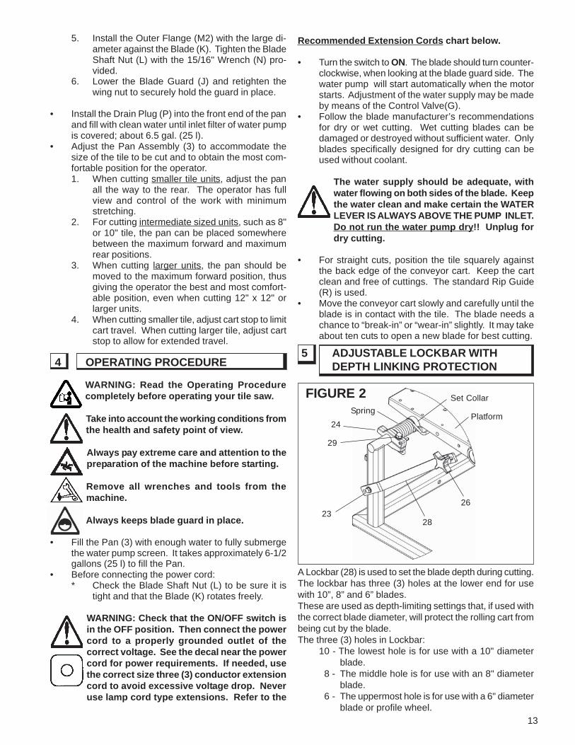
5 ADJUSTABLE LOCKBAR WITHDEPTH LINKING PROTECTION
A Lockbar (28) is used to set the blade depth during cutting.The lockbar has three (3) holes at the lower end for usewith 10”, 8” and 6” blades.These are used as depth-limiting settings that, if used withthe correct blade diameter, will protect the rolling cart frombeing cut by the blade.The three (3) holes in Lockbar:
10 - The lowest hole is for use with a 10" diameterblade.
8 - The middle hole is for use with an 8" diameterblade.
6 - The uppermost hole is for use with a 6" diameterblade or profile wheel.
4 OPERATING PROCEDURE
FIGURE 2 Set Collar
Spring
24
23
Platform
26
28
29
14
Good motor performance depends on propervoltage. Extension cords that are too longand/or too small in wire gauge reduce thevoltage to the motor under load. Useextension cords no smaller than indicatedbelow.
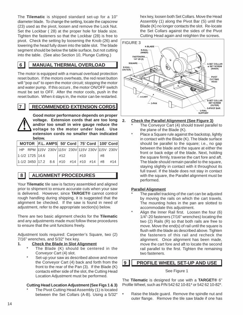
2. Check the Parallel Alignment (See Figure 3)* The Conveyor Cart (4) should travel parallel to
the plane of the Blade (K).* Place a Square rule against the backstop, lightly
in contact with the Blade (K). The blade surfaceshould be parallel to the square; i.e., no gapbetween the blade and the square at either thefront or back edge of the blade. Next, holdingthe square firmly, traverse the cart fore and aft.The blade should remain parallel to the square,staying slightly in contact with it throughout itsfull travel. If the blade does not stay in contactwith the square, the Parallel alignment must beperformed.
Parallel Alignment* The parallel tracking of the cart can be adjusted
by moving the rails on which the cart travels.The mounting holes in the pan are slotted toaccommodate this adjustment.
* Align the Inner Rail first. Loosen the four (6)1/4"-20 fasteners (7/16" wrenches) locating thetwo (2) Rails (R) so that both rails are free tomove. Move the end(s) of rail until the square isflush with the blade as described above. Tightenthe fasteners of this rail and recheck thealignment. Once alignment has been made,move the cart fore and aft to locate the secondrail parallel to the first. Tighten the remainingtwo fasteners.
The motor is equipped with a manual overload protectionreset button. If the motors overheats, the red reset buttonwill “pop out” to open the motor circuit; stopping the motorand water pump. If this occurs , the motor ON/OFF switchmust be set to OFF. After the motor cools, push in thereset button. When it stays in, the motor can be restarted.
9 PROFILE WHEEL SET-UP AND USE
Your Tilematic tile saw is factory assembled and alignedprior to shipment to ensure accurate cuts when your sawis delivered. However, since TARGET® cannot controlrough handling during shipping, it is suggested that thealignment be checked. If the saw is found in need ofadjustment, refer to the appropriate section(s) below.
There are two basic alignment checks for the Tilematicand any adjustments made must follow these proceduresto ensure that the unit functions freely.
Adjustment tools required: Carpenter’s Square, two (2)7/16" wrenches, and 5/32" hex key.1. Check the Blade in Slot Alignment
* The Blade (K) should be centered in theConveyor Cart (4) slot.
* Set-up your saw as described above and movethe Conveyor Cart (4) back and forth from thefront to the rear of the Pan (3). If the Blade (K)contacts either side of the slot, the Cutting HeadLocation Adjustment must be performed.
Cutting Head Location Adjustment (See Figs 1 & 3)* The Pivot Cutting Head Assembly (1) is located
between the Set Collars (A-B). Using a 5/32"
See Figure 1
The Tilematic is designed for use with a TARGET® 6"Profile Wheel, such as P/N 542 62 10-81* or 542 62 10-82*.
• Raise the blade guard. Remove the spindle nut andouter flange. Remove the tile saw blade if one has
The Tilematic is shipped standard set-up for a 10”diameter blade. To change the setting, locate the capscrew(23) used as the pivot, loosen and remove the Lock Nut.Set the Lockbar ( 28) at the proper hole for blade size.Tighten the fasteners so that the Lockbar (28) is free topivot. Check the setting by loosening the Knob (26) andlowering the head fully down into the table slot. The bladesegment should be below the table surface, but not cuttinginto the table. (See also Section 10, Plunge Cutting.)
MOTOR F.L. AMPS 50' Cord 75' Cord 100' Cord
HP RPM 115V 230V 115V 230V 115V 230V 115V 230V
1-1/2 1725 14.6 #12 #10 #8
1-1/2 3450 17.2 8.6 #10 #14 #10 #14 #8 #14
hex key, loosen both Set Collars. Move the HeadAssembly (1) along the Pivot Bar (S) until theBlade (K) no longer contacts the slot. Re-locatethe Set Collars against the sides of the PivotCutting Head again and retighten the screws.
6 MANUAL THERMAL OVERLOAD
7 RECOMMENDED EXTENSION CORDS
8 ALIGNMENT PROCEDURES
FIGURE 3
15
Before performing any maintenance, ALWAYSplace the machine on a level surface with themotor OFF and disconnect the electricalcurrent. Let the machine cool down!!
Your TARGET® tile saw is a ruggedly constructedmachine, engineered to give long, satisfactoryperformance. Simple daily maintenance and care will addto the life and productivity of your saw. After each day’suse: CLEAN THE MACHINE!!
* Turn off and unplug the saw before performingany maintenance.
* Keep the cart top clean and free for cuttings.To clean it, flush the top surface and grooveswith water.
* Drain, clean and refill the pan frequently. Flushthe coolant system with plenty of water, thendrain and refill the pan.
* If the water flow stops, check the water pump tosee if the shaft and impeller turn freely. See the
been installed. (Refer to Section 5, AdjustableLockbar, if needed)
• Install the profile wheel onto the spindle shaft upagainst the inner flange with the working surface tothe outside.
• Secure into place by reversing the outer flange andtightening the spindle nut. Lower the Blade Guard(J) back down over the profile wheel.
• Locate the material for profiling:1. Set the edge of the part to be shaped parallel to
the wheel.2. Locate the material under the wheel. Pull the
Conveyor Cart (4) with the material from underthe wheel to set proper cutting height.
3. Loosen the Locking Knob (C) and lower theCutting Head (1) so that the wheel just slightlymakes contact with the material.
4. Secure the Cutting Head (1) into position withthe Locking Knob (C) for cutting.
5. Note: Profiling usually takes several light passesto produce the best results. Set lower each timeuntil the desire depth has been reached.
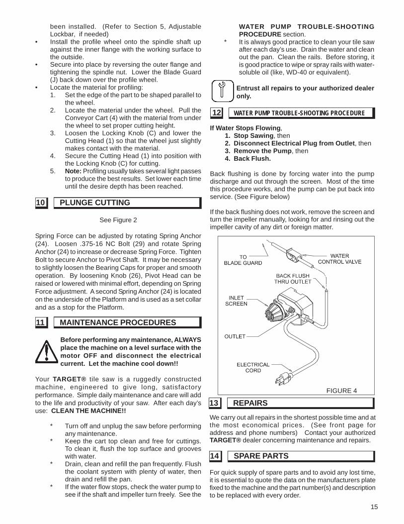
If Water Stops Flowing,1. Stop Sawing, then2. Disconnect Electrical Plug from Outlet, then3. Remove the Pump, then4. Back Flush.
Back flushing is done by forcing water into the pumpdischarge and out through the screen. Most of the timethis procedure works, and the pump can be put back intoservice. (See Figure below)
If the back flushing does not work, remove the screen andturn the impeller manually, looking for and rinsing out theimpeller cavity of any dirt or foreign matter.
FIGURE 4
11 MAINTENANCE PROCEDURES
12 WATER PUMP TROUBLE-SHOOTING PROCEDURE
10 PLUNGE CUTTING
See Figure 2
Spring Force can be adjusted by rotating Spring Anchor(24). Loosen .375-16 NC Bolt (29) and rotate SpringAnchor (24) to increase or decrease Spring Force. TightenBolt to secure Anchor to Pivot Shaft. It may be necessaryto slightly loosen the Bearing Caps for proper and smoothoperation. By loosening Knob (26), Pivot Head can beraised or lowered with minimal effort, depending on SpringForce adjustment. A second Spring Anchor (24) is locatedon the underside of the Platform and is used as a set collarand as a stop for the Platform.
WATER PUMP TROUBLE-SHOOTINGPROCEDURE section.
* It is always good practice to clean your tile sawafter each day’s use. Drain the water and cleanout the pan. Clean the rails. Before storing, itis good practice to wipe or spray rails with water-soluble oil (like, WD-40 or equivalent).
Entrust all repairs to your authorized dealeronly.
For quick supply of spare parts and to avoid any lost time,it is essential to quote the data on the manufacturers platefixed to the machine and the part number(s) and descriptionto be replaced with every order.
We carry out all repairs in the shortest possible time and atthe most economical prices. (See front page foraddress and phone numbers) Contact your authorizedTARGET® dealer concerning maintenance and repairs.
13 REPAIRS
14 SPARE PARTS
16
The instructions for use and spare parts found in this document are for information only and are not binding. As partof our product quality improvement policy, we reserve the right to make any and all technical modifications without
prior notice.
The manufacturer accepts noresponsibility caused by unsuitable
use or modifications.
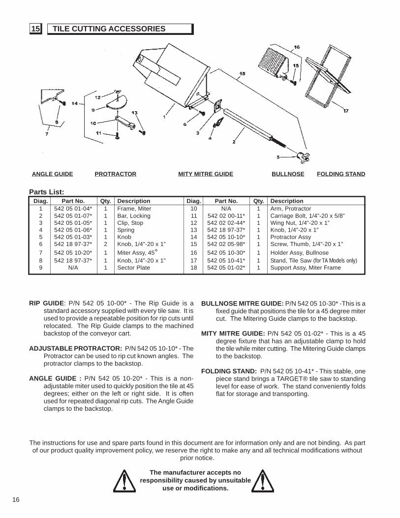
ANGLE GUIDE PROTRACTOR MITY MITRE GUIDE BULLNOSE FOLDING STAND
RIP GUIDE: P/N 542 05 10-00* - The Rip Guide is astandard accessory supplied with every tile saw. It isused to provide a repeatable position for rip cuts untilrelocated. The Rip Guide clamps to the machinedbackstop of the conveyor cart.
ADJUSTABLE PROTRACTOR: P/N 542 05 10-10* - TheProtractor can be used to rip cut known angles. Theprotractor clamps to the backstop.
ANGLE GUIDE : P/N 542 05 10-20* - This is a non-adjustable miter used to quickly position the tile at 45degrees; either on the left or right side. It is oftenused for repeated diagonal rip cuts. The Angle Guideclamps to the backstop.
BULLNOSE MITRE GUIDE: P/N 542 05 10-30* -This is afixed guide that positions the tile for a 45 degree mitercut. The Mitering Guide clamps to the backstop.
MITY MITRE GUIDE: P/N 542 05 01-02* - This is a 45degree fixture that has an adjustable clamp to holdthe tile while miter cutting. The Mitering Guide clampsto the backstop.
FOLDING STAND: P/N 542 05 10-41* - This stable, onepiece stand brings a TARGET® tile saw to standinglevel for ease of work. The stand conveniently foldsflat for storage and transporting.
Parts List:Diag. Part No. Qty. Description Diag. Part No. Qty. Description
1 542 05 01-04* 1 Frame, Miter 10 N/A 1 Arm, Protractor2 542 05 01-07* 1 Bar, Locking 11 542 02 00-11* 1 Carriage Bolt, 1/4”-20 x 5/8”3 542 05 01-05* 1 Clip, Stop 12 542 02 02-44* 1 Wing Nut, 1/4”-20 x 1”4 542 05 01-06* 1 Spring 13 542 18 97-37* 1 Knob, 1/4”-20 x 1”5 542 05 01-03* 1 Knob 14 542 05 10-10* 1 Protractor Assy6 542 18 97-37* 2 Knob, 1/4"-20 x 1" 15 542 02 05-98* 1 Screw, Thumb, 1/4"-20 x 1"
7 542 05 10-20* 1 Miter Assy, 45° 16 542 05 10-30* 1 Holder Assy, Bullnose8 542 18 97-37* 1 Knob, 1/4"-20 x 1" 17 542 05 10-41* 1 Stand, Tile Saw (for TA Models only)9 N/A 1 Sector Plate 18 542 05 01-02* 1 Support Assy, Miter Frame
15 TILE CUTTING ACCESSORIES
17
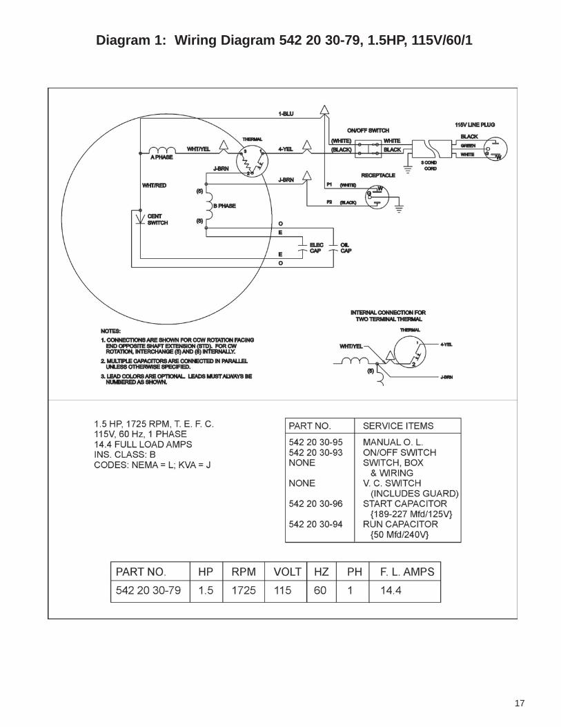
Diagram 1: Wiring Diagram 542 20 30-79, 1.5HP, 115V/60/1
18
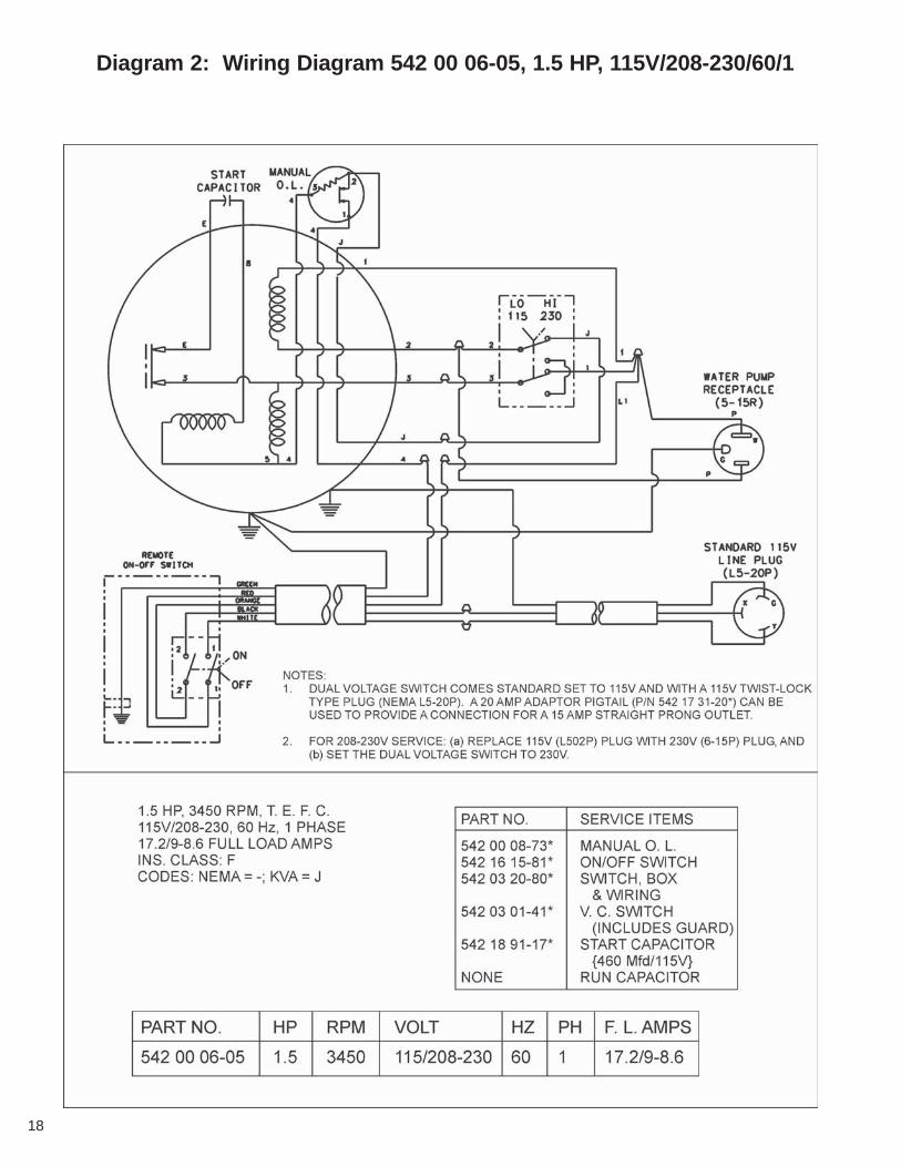
Diagram 2: Wiring Diagram 542 00 06-05, 1.5 HP, 115V/208-230/60/1

19
Serial Number:
Model Number:
Date of Purchase:
Where Purchased:
Target’s Gold Medal Equipment Warranty
New equipment sold by Target is warranted to be free from manufacturing defects in normal service for a periodof two (2) years from date of purchase by the original consumer purchaser.Component manufacturers offer separatewarranty periods. Call Technical Serives at 800-288-5040 forcomplete information.
Our obligation under this warranty is expressly limited to the replacement or repair at Electrolux ConstructionProducts North America, Olathe, Kansas 66061, or at a service facility designated by us, of such part or partsas inspection shall disclose to have been defective.
This warranty does not apply to defects caused by damage, unreasonable use, faulity repairs made by others(or defects caused by failure to provide reasonable maintenance, while in the possession of the consumer.)Further, the warranty is void if the product, or any of its components, are altered or modified by the consumer
Please record the Date of Purchase and the Serial Number, the Model Number of the euqipment and the Date ofPurchase of your equipment in the space below. When ordering service items, please have this informationavailable.
TARGET CUSTOMER SERVICECust. Service Phone.... 1-800-288-5040Cust. Service FAX ....... 1-800-825-0028
Target Corporate Office17400 West 119th StreetOlathe, Kansas 66061
Customer Service: 800-288-5040Customer Serv. Fax: 800-825-0028
Corporate Office: 913-928-1000Corp. Office Fax: 913-438-7951
Target InternationalCustomer Service: 913-928-1300
Customer Serv. Fax: 913-438-7938
Target CanadaCustomer Service: 800-461-9589
Customer Serv. Fax: 800-728-1907
Warning!
Some dust created by powered sanding, sawing, grinding,
drilling and other construction activities contains chemicals
known (to the State of California) to cause cancer, birth defects
or other reproductive harm.
Some examples of these chemicals are:
- Lead from lead based paints.
- Crystalline silica from bricks and cement and other masonry
products.
- Arsenic and chromium from chemically -treated lumber.
Your risk from these exposures varies, depending on how often
you do this type of work. To reduce your exposure to these
chemicals, work in a well-ventilated area, and work with
approved saftety equipment such as those dust masks that are
specially designed to filter out microscopic particals.
www.targetblue.com
From the Electrolux Group. The world’s No. 1 choice.
Target CaliforniaCustomer Service: 310-381-3100
Customer Serv. Fax: 310-381-3194