Successful approach to mitigate the asphaltenes ...
17
Vol.:(0123456789) 1 3 Journal of Petroleum Exploration and Production Technology https://doi.org/10.1007/s13202-021-01335-7 ORIGINAL PAPER-PRODUCTION ENGINEERING Successful approach to mitigate the asphaltenes precipitation problems in ESP oil wells Abotaleb Abdelazim 1 · Mahmoud Abu El Ela 2 · Ahmed El‑Banbi 3 · Helmy Sayyouh 2 Received: 28 May 2021 / Accepted: 13 October 2021 © The Author(s) 2021 Abstract This study introduces a comprehensive and cost-effective approach to diagnose and treat the asphaltenes precipitation problems in different downhole conditions. The proposed approach has been successfully applied in two oil wells (Well-I, and Well-II) located in the Western Desert of Egypt. The two wells produce oil of moderate to high oil gravity with low asphaltenes content using Electrical Submersible Pumps (ESP). In such operating conditions, solid deposits caused block- age at the pump intake and within the pumping stages in the two wells. This blockage led to a sharp decrease in oil produc- tion rate and a significant increase in the operating cost. The existing failure analysis procedure was not able to accurately identify the reasons for the blockage; accordingly, the treatment operations were unsuccessful. On the contrary, applying the proposed approach accurately (1) identified the type of the solid deposits, (2) solved the problem using proper treatment option with minimum cost, and (3) improved the oil production rate. The laboratory tests of the fluid and solid deposits showed that (1) the asphaltenes were unstable in the crude oil and acted as a glue for other minerals, and (2) the blockage was successfully diagnosed to confirm that the two wells had asphaltenes precipitation problem. The laboratory tests were extended to select optimum asphaltene dispersant for wells treatments. The field application results showed a significant increase in the oil production rate from 700 to 1600 STB/D in Well-I and from 470 to 1500 STB/D in Well-II. Moreover, the operating cost decreased considerably from 2.01 to 0.43 $/STB in Well-I, and from 4.37 to 0.52 $/STB in Well-II after applying the proposed approach. Keywords Asphaltenes precipitation · Asphaltenes stability · Asphaltenes dispersant · ESP plugging · Downhole treatment Abbreviations AD Asphaltenes dispersant ADT Asphaltenes dispersion test AOP Asphaltenes onset pressure API American petroleum institute ASTM American society for testing and materials BHFP Bottom-hole flowing pressure CCE Constant composition expansion CII Colloidal instability index CPA Cubic plus association CSI Colloidal stability index DBAR Density-based asphaltenes/resins DBCII Density-based colloidal instability index DBSAr. Density-based saturates/aromatics DHT Down hole temperature DIFA Dismantle inspection and failure analysis DSC Differential scanning calorimetry EoS Equation of state ESP Electrical submersible pump IR Infrared IP Institute of petroleum LAOP Lower asphaltenes onset pressure NIR Near-infrared OBMC Oil base mud contamination OPEX Operating expenditure PC-SAFT Perturbed-chain statistical association fluid theory POOH Pull out of hole A/R Asphaltenes/resins S/A r. Saturates/aromatics SARA Saturates, aromatics, resins, and asphaltenes SSB Single-phase sample bottle VSC Variable speed controllers UAOP Upper asphaltenes onset pressure * Abotaleb Abdelazim [email protected] 1 Khalda Petroleum Company, New Maadi, Cairo, Egypt 2 Cairo University, Giza, Egypt 3 The American University in Cairo, Cairo, Egypt
Transcript of Successful approach to mitigate the asphaltenes ...

Vol.:(0123456789)1 3
Journal of Petroleum Exploration and Production Technology https://doi.org/10.1007/s13202-021-01335-7
ORIGINAL PAPER-PRODUCTION ENGINEERING
Successful approach to mitigate the asphaltenes precipitation problems in ESP oil wells
Abotaleb Abdelazim1 · Mahmoud Abu El Ela2 · Ahmed El‑Banbi3 · Helmy Sayyouh2
Received: 28 May 2021 / Accepted: 13 October 2021 © The Author(s) 2021
AbstractThis study introduces a comprehensive and cost-effective approach to diagnose and treat the asphaltenes precipitation problems in different downhole conditions. The proposed approach has been successfully applied in two oil wells (Well-I, and Well-II) located in the Western Desert of Egypt. The two wells produce oil of moderate to high oil gravity with low asphaltenes content using Electrical Submersible Pumps (ESP). In such operating conditions, solid deposits caused block-age at the pump intake and within the pumping stages in the two wells. This blockage led to a sharp decrease in oil produc-tion rate and a significant increase in the operating cost. The existing failure analysis procedure was not able to accurately identify the reasons for the blockage; accordingly, the treatment operations were unsuccessful. On the contrary, applying the proposed approach accurately (1) identified the type of the solid deposits, (2) solved the problem using proper treatment option with minimum cost, and (3) improved the oil production rate. The laboratory tests of the fluid and solid deposits showed that (1) the asphaltenes were unstable in the crude oil and acted as a glue for other minerals, and (2) the blockage was successfully diagnosed to confirm that the two wells had asphaltenes precipitation problem. The laboratory tests were extended to select optimum asphaltene dispersant for wells treatments. The field application results showed a significant increase in the oil production rate from 700 to 1600 STB/D in Well-I and from 470 to 1500 STB/D in Well-II. Moreover, the operating cost decreased considerably from 2.01 to 0.43 $/STB in Well-I, and from 4.37 to 0.52 $/STB in Well-II after applying the proposed approach.
Keywords Asphaltenes precipitation · Asphaltenes stability · Asphaltenes dispersant · ESP plugging · Downhole treatment
AbbreviationsAD Asphaltenes dispersantADT Asphaltenes dispersion testAOP Asphaltenes onset pressureAPI American petroleum instituteASTM American society for testing and materialsBHFP Bottom-hole flowing pressureCCE Constant composition expansionCII Colloidal instability indexCPA Cubic plus associationCSI Colloidal stability indexDBAR Density-based asphaltenes/resinsDBCII Density-based colloidal instability index
DBSAr. Density-based saturates/aromaticsDHT Down hole temperatureDIFA Dismantle inspection and failure analysisDSC Differential scanning calorimetryEoS Equation of stateESP Electrical submersible pumpIR InfraredIP Institute of petroleumLAOP Lower asphaltenes onset pressureNIR Near-infraredOBMC Oil base mud contaminationOPEX Operating expenditurePC-SAFT Perturbed-chain statistical association fluid
theoryPOOH Pull out of holeA/R Asphaltenes/resinsS/Ar. Saturates/aromaticsSARA Saturates, aromatics, resins, and asphaltenesSSB Single-phase sample bottleVSC Variable speed controllersUAOP Upper asphaltenes onset pressure
* Abotaleb Abdelazim [email protected]
1 Khalda Petroleum Company, New Maadi, Cairo, Egypt2 Cairo University, Giza, Egypt3 The American University in Cairo, Cairo, Egypt

Journal of Petroleum Exploration and Production Technology
1 3
WAT Wax appearance temperatureWHFP Well head flowing pressureXRD X-ray diffractionXRF X-ray fluorescence
List of symbols∈Asph Dielectric constant value of asphaltene∈Sat Dielectric constant value of saturates∈Arom Dielectric constant value of aromatics∈Res Dielectric constant value of resins
Introduction
Asphaltenes are molecular substances that are found in crude oil along with resins, aromatics, and saturates (i.e. saturated hydrocarbons such as alkanes). Speight (1998) defined the asphaltenes structure as a hypothetical model charac-terized by high molecular weight which is the most polar and aromatic fraction in the crude oil. This polar nature of asphaltenes is imparted by heteroatoms like nitrogen, sulfur, and oxygen present in their structure. The asphaltenes mol-ecules tend to self-associate even at low concentrations due to the high polarity of asphaltenes, and they precipitate at a certain temperature, pressure, and composition (Arya et al. 2017; El-hoshoudy et al. 2020). Usually, asphaltenes exist in the oil reservoir and act as cholesterol in the blood. The deposit of asphaltenes leads to several operation problems including formation damage and equipment failure. These problems cause a reduction in the oil production rate (Guan et al. 2018; Shoukry et al. 2020).
The asphaltenes deposition during the production of crude oil is problematic and costly. The most susceptible places of the asphaltenes deposition are around the wellbore region, perforation tunnels, well tubing, flowlines, separa-tors, pumps, tanks, and other production equipment. The factors contributing to asphaltenes precipitation include (1) the changes of the pressure, temperature, and crude oil composition during the production stage, (2) the presence of CO2, and (3) the existence of tubing restrictions (Man-soori, 1997). The asphaltenes deposition can cause dam-age to ESP components (pump motor, pump intake, power cable, gas handling equipment, and downhole sensors). It reduces the lifetime of the ESP. The centrifugal forces of the ESP increase the quantities of the asphaltenes precipitation (Limanowka et al. 1999; Al-Qasim et al. 2018).
The asphaltenes stability depends on the asphaltenes to resins ratio rather than the absolute percentage of the asphaltenes in the crude oil. If there are not enough res-ins to stabilize the asphaltenes, the light crude oil can be subject to asphaltenes precipitation, flocculation, and deposition (Haskett and Tartera 1965; Ali et al. 2021a, b). Leontaritis and Mansoori (1988) highlighted that the
Algerian Hassi-Messaoud crude oil has asphaltenes depo-sitional problems with the presence of only 0.062 wt% of the asphaltenes content, while Venezuela-Boscan crude oil has no asphaltenes precipitation problem despite the high asphaltenes content of 17.2%.
The precipitation of asphaltenes can be controlled by modifying the production techniques and applying chemi-cal treatment methods. The modifications of the production techniques include reducing the shear rate, eliminating the incompatible material with asphaltic crude oil, and mini-mizing the mixing of lean feedstock liquids into asphaltic crude streams. However, the most common chemical treat-ment methods are the injection of Asphaltenes Dispersant (AD) or aromatic solvents. The function of the asphaltenes inhibitors is similar to the behavior of the resins activity in the natural environment. It covers the asphaltenes mol-ecules to avoid their flocculation and deposition. The ADs act as surfactants by dispersing the asphaltenes particles in the crude oil. The polar head-groups in ADs interact with asphaltenes aggregations, and the long alkyl chains on the periphery of the asphaltenes aggregate. It is helps to change the polarity of the aggregate and make it dispersible in the crude oil (Kelland 2016; Limanowka et al. 1999). However, the aromatic solvents are used to reinstate productivity by removing such deposits from the reservoir or tubing through the non-producing string. The popular aromatic solvents include xylene, benzene, toluene, and ethylbenzene. Gener-ally, xylene is used in the well-stimulation and workover operations to minimize the severity of the deposition prob-lems. The solvents dissolve the organic deposits till reaching the saturation level. At the same time, the xylene should be removed from the well promptly to prevent precipitation of xylene and asphaltenes. The delay in removing xylene leads to severe formation damage due to the accumulation of the deposits. Accordingly, solvents should be handled with care and removed at the right time (Campen et al. 2020; Khor-mali et al. 2021).
Limanowka et al. (1999) proposed new production tech-niques for inhibiting asphaltenes precipitation in the ESP completion. The developed techniques include (1) using Variable Speed Controllers (VSC) combined with oversized pumps; (2) increasing the vein height of the pump impellers; (3) coating the internal surface of the pump intake, stages and motor; and (4) reducing the pressure drop at pump intake. It should be highlighted that using VSC combined with oversized pumps and higher impeller vein heights can reduce asphaltenes deposition, improve the pump perfor-mance, and increase ESP running time. In addition, coat-ing the internal surface of the pump stages, pump intake, and pump discharge contribute significantly to successful combat of asphaltenes precipitation. It is used to eliminate casting surface imperfections and produce internal surfaces with low friction and good properties. Moreover, it should

Journal of Petroleum Exploration and Production Technology
1 3
be highlighted that using production tubing with a rough surface generates a turbulent flow that can increase the pres-sure drop in the tubing. Therefore, increasing the screen area of the pump intake and using high-quality production tubing minimize the pressure drops in the wellbore which reduce the asphaltenes deposition. It is rare to have a considerable improvement in the ESP running time by applying one of the previous techniques but through a combination of them. The production techniques are selected on a case-by-case basis to improve the pump performance, maximize the production rate, extend the pump lifetime, and decrease the operating cost (Limanowka et al. 1999).
This paper presents a comprehensive and integrated approach including experimental work to diagnose and treat the asphaltenes precipitation problem in ESP oil wells. The integrated approached is applied in several wells, and the field results are reported.
Asphaltenes identification methods
Once the well is plugged with solid deposits, the type of the deposits should be identified to accurately select proper treatment option. This section presents the identification methods for the solid deposits chemical composition and the severity of asphaltenes precipitation, together with the Asphaltene Dispersant Test (ADT) results.
Chemical composition of the solid deposits
The chemical composition of the solid deposits can be iden-tified by several methods including:
1. X-Ray Diffraction (XRD),2. X-Ray Fluorenes (XRF),3. Infrared (IR) Spectrum, and4. Saturates, Aromatics, Resins, and Asphaltenes (SARA)
analysis (for organic scale deposits)
The XRD method is a non-destructive test used to analyze the structure of crystalline materials. It is used to evalu-ate the chemical composition of minerals, polymers, corro-sion products, and unknown materials. The quantification is achieved by comparison with standard minerals samples. The common minerals which are identified by the XRD techniques include the following: the total clays, K-feldspar, quartz, plagioclase, calcite, dolomite, pyrite, anhydrite, and halite. On the other hand, the XRF method is an elemental analysis technique that provides quantitative chemical infor-mation about the materials. It identifies the major elements in weight percent and the trace elements in parts per mil-lion (ppm). However, the objective of the IR-spectroscopy technique is to characterize the inorganic and organic scale
deposits using IR-spectrometer. The electromagnetic spec-trum infrared region allows the symmetric bonds to stretch, bend, and vibrate. The IR-spectroscopy can be analyzed in three ways by measuring absorption, emission and reflec-tion. This relationship can be tested to better explain the chemical structure of the material (Peksoz et al. 2011).
Moreover, the SARA analysis techniques are used for characterizing the organic deposit and group composition of crude oils. Its results are the fractions of saturates, aro-matics, resins, and asphaltenes. The SARA fractionating is a chromatographic procedure based on the difference in solubility and polarity of the four fractions with respect to certain solvents (Ekholm et al. 2002). There are several approaches for separating SARA components including (1) gravity-driven chromatography separation, (2) thin-layer chromatography, (3) high-pressure liquid chromatography, and (4) microfluidic SARA analysis (Maze) (Sieben et al., 2017). The SARA analysis is performed by standard meth-odologies of the American Society of Testing and Materi-als (ASTM) and the Institute of Petroleum (IP) (Ekholm et al. 2002; ASTM D4124–09). To perform SARA analysis, ASTM 2007 is employed to separate crude oil into Asphal-tene, Saturates, Aromatics and Resins. In this analysis, a certain amount of crude oil is weighted out. Then, the asphaltene is separated from the sample by adding n-pentane or n-heptane. The asphaltene is obtained from the residue on the filter paper, while the maltenes (saturates, aromat-ics and resins) are obtained from the filtrate. The maltenes are charged into the top of a glass chromatographic column packed with activated silica gel and alumina. The n-alkanes and toluene are added to the maltene to separate the Satu-rates and Aromatics, respectively. Afterward, methanol is added to separate the Resins as summarizes in Fig. 1 (ASTM 2007–2007).
Severity of the asphaltenes precipitation
Several methods and techniques are used to assess the sever-ity of the asphaltenes precipitation. The main methods are (1) de Boer plot, (2) Colloidal Instability Index (CII) and Colloidal Stability Index (CSI) correlations, and (3) oil den-sity correlations. These methods provide screening criteria for defining the tendency of asphaltenes to precipitate from crude oil.
De Boer et al. (1995) proposed the first quantitative method to screen the reservoir fluids for their tendency of asphaltenes precipitation. This method includes a cross-plot between (1) the in situ oil density on the X-axis, and (2) the difference between the reservoir and saturation pressures in the Y-axis. The de Boer plot includes two curves that iden-tify the boundary between the asphaltenes precipitation zone and the stable zone. It is a global plot, and it is an extremely conservative prediction method (Gonzalez et al. 2016). The

Journal of Petroleum Exploration and Production Technology
1 3
data of any reservoir fluid can be imposed into the plot to check the tendency of the asphaltenes precipitation based on the location of the reservoir fluid data against the location of the asphaltenes precipitation and stable zones on the plot (Fakher et al. 2020; Guzmán et al. 2017).
The CII method considers crude oil as a colloidal struc-ture. The calculations of the CII method are based on oil composition. It is the ratio of the sum of saturates and asphaltenes fractions (flocculent elements) to the sum of the aromatics and resins fraction (absorption elements) as shown in Eq. 1. When the calculated CII value is less than 0.7, the reservoir fluid is located in the stable conditions zone. However, when the calculated value ranges between 0.7 and 0.9, the reservoir fluid is considered in mild problem condi-tions. If the CII value is greater than 0.9, the reservoir fluid is located in the unstable conditions (Ashoori et al. 2017; Guzmán et al. 2017).
Likhatsky and Syunyaev (2010) determined dipole moments for the structure of the asphaltenes molecules. They recognized a change in the polarity of the asphaltenes at the unstable and stable conditions. It was found that the asphaltenes from unstable crude oils are more polar than from stable crude oils. Equation 2 presents the CSI correla-tion. For the unstable crude oil, the dielectric values ( ∈ ) of asphaltenes and resins are 18.4 and 3.8, respectively, while the values for stable crude oil are 5.5 and 4.7, respectively. However, the dielectric values ( ∈ ) of saturates and aromat-ics are 1.92 and 2.379 in all crude oils (Punase et al. 2016). Accordingly, the CSI method was proposed based on the oil compositions and polarity of the asphaltenes, resins, aromat-ics, and saturates. If the calculated CSI is less than 0.95, the crude oil is stable with no risk of asphaltenes precipitation.
(1)CII =(Asphaltenes inwt%) + (Saturates inwt%)
(Resins inwt%) + (Aromatics inwt%)
Otherwise, the crude oil is unstable and susceptible to asphaltenes precipitation problems (Ali et al. 2021a, b).
Sulaimon et al. (2020a, b) developed three correla-tions (three plots) based on oil density and the ratio of Asphaltenes/Resins (A/R), the ratio of Saturates/Aromatics (S/Ar), and the CII value. These plots can identify the ten-dency of the asphaltenes precipitation. In each plot, an enve-lope between the stable and unstable regions of asphaltenes precipitation is considered. The three asphaltenes stability envelopes are (1) oil density versus the ratio of Density-Based Asphaltenes/Resins (DBAR), (2) oil density versus Density-Based Colloidal Stability Instability Index (DBCII), and (3) DBAR versus the ratio of Density-Based Saturates/Aromatics (DBSAr). The three relationships were developed to predict asphaltenes stability based on oil density. The oil density can be easily determined without the need to wait for the time-consuming SARA analysis or its cost. Without SARA analysis, the new models can produce a dependable, efficient, and accurate assessment of asphaltene precipitation potential (Sulaimon et al. 2020a, b).
ADT procedures and theory
The ADT test is a quick and dependable method for deter-mining the effectiveness of asphaltene inhibitors and dis-persants. Before and after adding AD to the crude oil, a laser dispersion tester is used to detect the flocculation and precipitation of asphaltene particles. In this technique, a pulsed near-infrared (IR) light source (850 nm) is used to determine a sample's average transmittance. A fraction of untreated (blank) and treated crude oil is titrated with
(2)
CSI =
(
∈Asph
)
(Asphaltenes inwt%) +(
∈Sat
)
(Saturates inwt%)(
∈Res
)
(Resins inwt%) +(
∈Arom
)
(Aromatics inwt%)
Fig. 1 Typical schematic for separating crude oil into SARA components (after Auflem 2002)
Crude Oil
Maltenes
Aromatics AsphaltenesResinsSaturates
Dilute with n-alkane
n-alkane
Precipitate
Toluene Toluene/methanol
Adsorb with silicaelute with

Journal of Petroleum Exploration and Production Technology
1 3
10 mL of pentane. After that, the samples are centrifuged at 2500 rpm for three minutes. Then, the mixture is added to ADT tubes to measure the transmittance. The percent of precipitation due to gravity is recorded against time. Effi-cient asphaltene dispersant lowers the percent transmis-sion compared to untreated crude oil. It remains relatively unchanged during the full length of the test. According to the manufacturer's instructions, the treatment levels of a good commercial product are usually between 50 to 400 ppm of AD concentration (Juyal et al. 2011).
Approach
The main objective of this study is to provide a complete and applicable approach for diagnosing and treating the down-hole asphaltenes precipitation problems. Figure 2 represents a schematic diagram for the proposed approach. It includes the following main steps:
1. Problem diagnosis2. Data collection and laboratory analysis (surface and
downhole samples)3. Development and validation of the thermodynamic
model4. Evaluation of the proposed solution options
a. Changing the operating conditionsb. Chemical treatment solutions
5. Pilot implementation, well performance monitoring, and economic evaluation
6. Full-field implementation
The diagnosis of the solid deposits problem is based on the changes in the relationship between the production rate and the bottom-hole flowing pressure (BHFP) with time. These relations should be consistent with time in the normal operating conditions. Generally, the BHFP should be declin-ing with the production rate. In case there is a solid deposits problem, the BHFP increases with decreasing the production rate (Ilk et al. 2007; Anderson and Thompson 2014).
Once the solid deposits problem is identified, it is recom-mended to collect surface oil samples, downhole oil sam-ples, and solid samples. The representative fluid and solid samples are essential to obtain reliable results. The precau-tions for the downhole samples are performed by (1) using Single-phase Sample Bottle (SSB), and (2) maintaining Oil Base Mud Contamination (OBMC) to be less than 5%. All of these precautions should be considered to avoid any sig-nificant effect on the laboratory results (Mullins et al. 2007).
The surface samples are used as preliminary diagnos-tics in the flow assurance problems. They are inexpensive
and easy to be collected. The required laboratory tests for these samples are basic crude oil analysis (e.g. °API, wax content, asphaltenes content, SARA, wax appearance tem-perature (WAT), and fluid compositions). The results and the analyses of these tests are used as a qualitative assess-ment for the reasons of the solid precipitations. However, the testing sequences of the downhole samples are used to assess the precipitation of asphaltenes at downhole pressure and temperature. Representative reservoir fluids samples are essential prerequisites for providing quality data. Therefore, several downhole samples should be extracted. Then, the best representative sample is selected to be analyzed and studied according to the following procedures and condi-tions (Williams 1994): (1) the bottom hole flowing pressure during sampling should be above the bubble point pressure, (2) the bubble point pressure of the extracted sample (at either ambient or reservoir temperature) should be checked to confirm there is no gas leakage during sampling and ship-ping process, (3) the opening of the sample in the labora-tory should be carried out at the reservoir temperature, and the opening pressure should be equal to the downhole sam-pling pressure or above the bubble point pressure, (4) visual inspection should be performed to check whether sediments or aqueous phase exist in the sample, and (5) the oil base mud contamination (OBMC) while sampling should be less than 5%. Once the representative sample is selected, the fol-lowing tests are performed to validate the downhole samples (Mullins et al. 2007).
1. Constant Composition Expansion (CCE) test (at least for two temperature points)
2. Asphaltenes Onset Pressure (AOP) test at the operating temperature
3. Upper Asphaltenes Onset Pressure (UAOP) test4. Lower Asphaltenes Onset Pressure (LAOP) test5. AOP test with different concentrations of chemical fluid
at the operating temperature
The results of the downhole fluid tests are used to con-struct the asphaltenes deposition envelope. It is essential to determine the asphaltenes precipitation region on the phase envelope. The change of the operating conditions outside the asphaltenes precipitation region is one of the possible treat-ment solutions that can be considered to avoid asphaltenes precipitation. The challenges of downhole sampling include (1) operation restrictions and well configuration constraints, and (2) the AOP tests usually need special laboratories that are not available in all countries and sometimes the oil sam-ples are shipped abroad to special laboratories.
The continuous improvement can be applied by collecting solid samples from any completion after Pulling Out of Hole (POOH) and performing a complete solid precipitation anal-ysis. The solid deposition samples tests are used to define

Journal of Petroleum Exploration and Production Technology
1 3
the chemical structure of the deposits by conducting organic and inorganic extraction. The SARA test is performed for the organic deposits, but the XRD and XRF tests are performed for the inorganic deposits. However, the IR-spectrum test is carried out for organic and inorganic deposits (Akbar and Saleh 1989).
After the data are collected and the laboratory analyses are performed, a thermodynamic model should be developed
and validated with experimental observations. Many general thermodynamic models are available in the literature based on thermodynamic and chemical theories. They include the cubic solid Equation of State (EoS), Cubic Plus Association Equation of State (CPA-EoS), and Perturbed-Chain Statisti-cal Associating Fluid Theory Equation of State (PC-SAFT-EoS) (Abouie et al. 2016; Li and Firoozabadi 2010; Sab-bagh et al. 2006; Shoukry et al. 2019). These models can be
Fig. 2 Approach for treatment and mitigation of the asphaltenes precipitation problem

Journal of Petroleum Exploration and Production Technology
1 3
used to predict the behavior of asphaltenes precipitation at different operating conditions. The existing models can be applied using commercial software to predict more accurate asphaltenes precipitation conditions.
Based on the thermodynamic model results, two available solutions should be evaluated. The two options are either (1) changing the operating conditions to be outside the solid precipitation region in the asphaltenes deposition envelope or (2) conducting chemical injection with optimum concen-tration of asphaltenes dispersant. Generally, the solubility of asphaltenes decreases with the decrease in pressure. There-fore, changing the operating conditions can be applied by keeping the BHFP above the AOP. If changing the operat-ing conditions is not applicable, the chemical treatment is recommended. The chemical injection should be carried out below the asphaltenes precipitation point to provide enough time for the chemical reaction to occur. The most proper and cost-efficient chemical injection technique is conducted by injecting chemicals using a capillary tube in oil wells oper-ated by ESP (Abdallah et al. 2010).
After the proposed solution options (changing the operat-ing conditions or applying chemical treatment) are evaluated based on the available data and the laboratory results, a pilot implementation should be conducted to validate the pro-posed treatment before the full field application. Monitoring the well performance can help in judging the success of the actual pilot implementation. During the pilot implementa-tion, the economic criteria are continuously monitored to evaluate the operating cost and the well performance for each step of the treatment. The monitoring, evaluation, and improvement steps during the pilot implementation are man-datory to reduce the operating cost and increase the effi-ciency of the chemical treatment before the full field applica-tion (Abu El Ela et al. 2014).
Field application
The proposed approach was applied to treat several oil wells in the Western Desert of Egypt. Generally, the pro-duction contribution of ESP wells is a significant portion of the total production in the Western Desert (Mahgoub and Shahat 2005). Therefore, this study was carried out to treat plugging problems of several ESPs. The ESPs plug-ging problem has occurred in several oil wells within five reservoirs (A, B, C, D, and E). The ESP wells’ perfor-mance showed a sharp reduction by 65 to 75% of the oil production rate. This reduction was due to organic and inorganic solid precipitation in the pump intake and within the pump stages for several pumps. Figures 3, 4, 5 and 6 show photos of a few pumps’ equipment. These photos were taken during the POOH and Dismantle Inspection and Failure Analysis (DIFA). These ESPs components
were visually inspected. Some components were com-pletely blocked and damaged due to solid precipitation. Consequently, the oil production rate decreased in the cor-responding wells.
Fig. 3 Intake of ESP for Well-I during POOH
Fig. 4 Intake of ESP for Well-I during DIFA

Journal of Petroleum Exploration and Production Technology
1 3
The old treatment methods to remove the solids from the plugged wells included: (1) continuous diesel injection from the annulus, and (2) mixing acid, xylene, and diesel with different percentages to backwash the pump parts as a periodic cleaning job. The old methodology was applied in several wells to remove the solids and improve oil produc-tion performance. In this work, the data of five wells (Well-I, Well-II, Well-III, Well-IV, and Well-V) are presented and discussed to represent the five reservoirs (A, B, C, D, and E) as listed in Table 1. The old treatment methods were evalu-ated considering the economic criteria and the improvement in the wells production performance as shown in Table 2. The economical evaluation concluded that the extra operat-ing cost ranged from 2 to 6$/STB. The reasons behind the additional cost were the number of diesel backwash jobs, the amount of the injected diesel per day, and the cost of replacing the failed ESP. After evaluating the wells’ perfor-mance combined with the economical evaluation results, it was clear that the old treatment methods were ineffective as they resulted in significantly increased operating costs.
These results are consistent with the research work of Abdal-lah et al. 2010. He concluded that mitigating asphaltenes precipitation by using diesel is not effective and causes significant waste of money, while aromatic solvents can improve the cleaning efficiency and reduce the soaking time.
To improve the economic evaluation, reduce the operat-ing cost, and increase the production performance in the five reservoirs, the selection of proper treatment methods was mandatory. Accordingly, the proposed integrated approach has been applied and explained below.
Data collection, sampling and testing
To apply the proposed approach and to accurately iden-tify the type of the solid deposits and the proper treatment method, a huge amount of data was collected from the five wells. The collected data include the wells production per-formance, wells history, wells configurations, daily injection rate of diesel, and the number of diesel backwash injection jobs per well. In addition, the following sampling program was performed:
1. five surface samples were extracted from Reservoirs A, B, C, D, and E
2. one downhole sample was extracted from Reservoir-A3. two solid deposit samples were collected from the ESPs
of Reservoirs-A and B
The sequences of the surface and downhole samples tests were applied as mentioned before. The basic crude oil analy-sis and WAT tests were conducted for all surface samples (five samples). However, the SARA analysis was carried out for the samples of Reservoir B, C, D, and E. Moreover, the fluid composition, SARA analysis and wax appearance tem-perature test at 2000 psi (operating pressure) were carried out for the downhole sample of Reservoir A. Furthermore, the XRD, XRF, and SARA analyses were conducted for the solid deposits samples which were extracted from Reser-voirs A and B. In addition, the IR-spectrum test was carried out for the solid deposits sample which was extracted from Reservoir A.
Fig. 5 Housing of ESP for Well-II during DIFA
Fig. 6 Impellers of ESP for Well-II during DIFA
Table 1 List of the field applications
Fields Reservoirs Wells Application of the old treatment strategy
Application of the new treatment strategy
One A W-I Yes YesB W-II Yes Yes
Two C W-III Yes NoThree D W-IV Yes NoFour E W-V Yes No

Journal of Petroleum Exploration and Production Technology
1 3
Analysis of the laboratories results
The preliminary screening criteria using the surface and downhole samples are shown in Tables 3 and 4. Table 3 presents the basic crude oil analysis for surface samples of Reservoirs A, B, C, D, and E. It is clear that the wax con-tent of the collected surface samples ranges from 9.1 to 19 wt% (extremely waxy oil) with oil gravity ranging from 36 to 41.5 ºAPI and a low pour point ranging from 86 to 93 °F. Moreover, the sulfur content of the collected samples
ranges from 190 to 500 ppm. However, Table 4 illustrates the SARA analysis results. The SARA analysis results clarified that the crude oil of all samples has low asphaltenes content that ranges from 0.3 to 1.29 wt% as shown in Table 4. In addition, the analysis showed that the collected samples have high saturates with low resins and aromatics. All of these observations were the first indication of the instability of asphaltenes in crude oil.
It should be highlighted that the WAT was measured for the surface and downhole samples. The WAT of the five
Table 2 Economic evaluation for the old treatment methods in the five oil wells
Items/wells Before injecting AD ‘Old treatment strategy’
Well-I Well-II Well-III Well-IV Well-V
Duration (months) 6.5 7 3.0 5.0 5.0Cumulative oil produc-
tion (MSTB)130 98 72 237 203
Differ in the cumula-tive oil production (MSTB)
167 245 71 136 92
Total additional cost ($MM)
0.33 0.35 0.31 1.20 1.30
Extra cost per bbl ($/STB)
2.01 4.37 4.28 5.06 6.4
Causes of the total additional cost
Three diesel backwash jobs and one ESP replacement
Three diesel backwash jobs and one ESP replacement
Four diesel backwash jobs and one ESP replacement
Four diesel backwash jobs and injected 20.8 Mbbl diesel
Four diesel back-wash jobs, one ESP replacement, and injected 18.9 Mbbl diesel
Table 3 Basic crude oil analysis for surface samples
Reservoir APIº Pour point (°F) Wax content (wt%) Asph. content (wt%)
Total sulfur (ppm) Molecular weight (g/mole)
WAT (°F) DHT (°F)
ASTM D-1298 ASTM D-97 UOP-64 IP-143 ASTM D-4294 – DSC Electrical sensorA 41.5 86 9.31 0.43 500 127.8 159.08 262B 36.13 97 10.01 0.3 370 164.8 196.34 251C 37.97 93 9.1 1.29 480 220.24 151 200D 37.8 89 16.2 0.53 350 180 185 268E 41.44 90 19.13 0.7 190 156.1 191 270
Table 4 Results of the SARA analysis
Reservoir Sampling Point Saturates (wt%) Aromatics (wt%) Resins (wt%) Asphaltenes (n-c7) (wt%)
Technique
A Downhole 76.8 19.66 3.12 0.43 IP-143B Surface 70.3 23 6.4 0.3 Maze microfluidicC Surface 44.78 34 19.92 1.29 IP-143D Surface 75.42 19.56 4.48 0.53 LatrascanE Surface 72 21.5 5.5 0.7 IP-143

Journal of Petroleum Exploration and Production Technology
1 3
surface samples was measured at the ambient pressure as shown in Table 3. The results showed that the WAT of the five surface samples ranged from 151 to 196 °F, while the operating downhole temperature for the same wells ranged from 200 to 270 °F. On the other hand, the WAT of the downhole sample of Reservoir A was measured at the oper-ating pressure (2000 psi) using Near-Infrared (NIR) scan test. The result indicated that the WAT of the downhole sam-ple is 200 °F; while, the operating downhole temperature is 262 °F, which is very close to the WAT measurements of the surface samples. Consequently, the WAT measurements of surface and downhole samples are lower than the operating downhole temperature by + 50 °F. That means the first crys-tal of wax is not formed and disappears under the existing operating condition. Therefore, these results eliminated the possibility of downhole wax precipitation.
To check the possibility of asphaltenes precipitation from the crude oil, several correlations were used includ-ing de Boer plot, CII, CSI, and oil density correlations. The asphaltenes screening criteria using the de Boer method showed that the two oil samples of Reservoirs D and E are located in the “severe problem” region and the other three oil samples of Reservoirs A, B, and C are located in the “mild problem” region as shown in Fig. 7. In addition, the analysis of the CII results showed that the oil samples of Reservoirs A, B, D, and E are located in unstable region and the oil sample of Reservoir C falls in the uncertain region as illus-trated in Fig. 8. Similarly, the CSI calculations showed that the oil samples of Reservoirs A, B, D, and E are unstable. The CSI of Reservoirs A, B, D, and E are 1.7, 2.6, 2.4, and 2.1, respectively, which are higher than the standard stable value of 0.95. However, the oil sample of Reservoir C is stable as its CSI is 0.7.
The oil density correlations (DBAR, DBSAr, and DBCII) were also used to check the possibility of asphaltenes pre-cipitation for the oil samples of Reservoirs A, B, C, D, and E. The DBAR, DBSAr, and DBCII correlations showed that
the fluids of the five samples are located in the unstable region as demonstrated in Figs. 9, 10 and 11. The results of all fluid correlations (de Boer plot, CII, CSI, and oil density correlations) confirm that the five reservoir fluids tend to have asphaltenes precipitation. In addition, the mild problem is prone to be a severe problem due to (1) the pressure losses
sligh
t pro
blem
1<S
S<2
Fig. 7 De Boer plot for the fluid samples of reservoirs A, B, C, D, and E
Fig. 8 Colloidal Instability Index (CII) for the fluid samples of reser-voirs A, B, C, D and E
A
BC
D
E
0.00
0.05
0.10
0.15
0.20
0.25
0.30
0.80 0.85 0.90 0.95 1.00Oil Density at 15 ºC (g/cc)
Stable region
Unstable region
Den
sity
-Bas
ed A
spha
ltene
/Res
ins
Rat
io
(DB
AR
Rat
io) (
wt%
)
Fig. 9 Asphaltenes stability plot using the density-based asphaltene resin (DBAR) ratio technique
A
B
C
D
E
0.5
1.0
1.5
2.0
2.5
3.0
3.5
4.0
4.5
5.0
0.10 0.12 0.14 0.16 0.18 0.20 0.22 0.24 0.26 0.28 0.30
Den
sity
- Bas
ed o
n S
atur
ates
/Aro
mat
ics
(DB
SA
r R
atio
) (w
t%)
Density- Based on Asphaltenes /Resins (DBAR Ratio) (wt%)
Stable region
Unstable region
Fig. 10 Asphaltenes stability plot using the density-based on satu-rates/aromatics (S/Ar.) and asphaltenes/resins (A/R) techniques

Journal of Petroleum Exploration and Production Technology
1 3
around the ESPs and (2) the centrifugal forces of the pumps inside the wells.
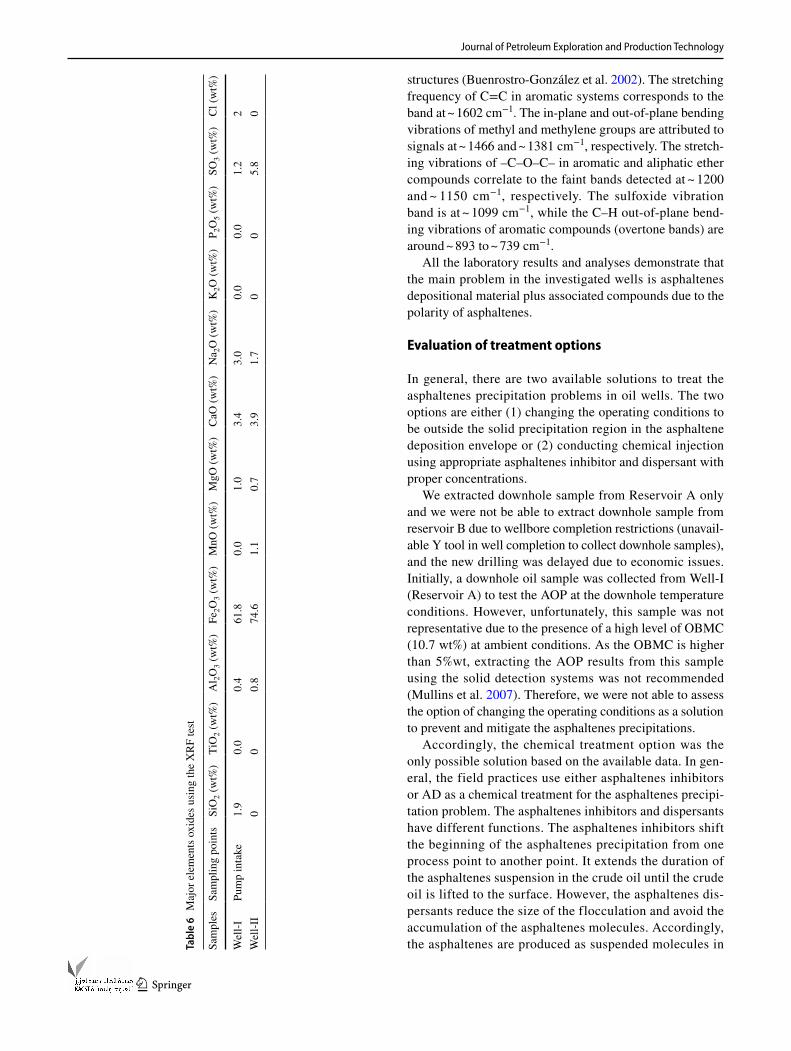
Characterizing the chemical composition of the solid deposits is important for diagnosing and treating the asphaltenes precipitation problem. Therefore, XRD, XRF, IR-Spectrum test, and SARA analyses for the collected solid deposit samples of Reservoirs A and B were carried out to check the chemical composition of the solid deposit samples. The results of the separated solid deposits samples showed that the content of the organic and inorganic compounds is 17.5 wt% and 82.5 wt%, respectively. The reasons for the majority of inorganic materials can be clarified by this con-cept: Asphaltene and its flocculates are known to be surface-active agents for other materials. In addition, asphaltene is a highly polar compound. It acts as glue for the fluctuation of other components by self-association and cross-association. Therefore, the composition of solid sludge is complex, e.g., inorganic salts, organic, sediments, sands, and scale. In this way, the organic material acts only as nucleus for the floc-culation of the inorganic components. In a previous study,
Salgaonkar and Danait (2012) reported the same percent-age of organic and inorganic components (79.6% inorganic, 19.4% organic) for asphaltene precipitation problem. The nature of asphaltenes deposits varies regionally and the con-centrations of the different components should be changed from reservoir to another (Salgaonkar and Danait 2012; Chouparova et al. 2004).
On other hand, the XRD analysis demonstrated that the solid deposits were made up of mainly mineral material including magnetite (Fe3O4) and siderite (FeCO3) material as shown in Table 5. However, the XRF analysis showed that the solid deposits were made up of mainly minerals materials including iron oxide (Fe2O3) and other minerals as illustrated in Table 6. The results of the XRD and XRF analyses are only indicative of asphaltenes precipitation materials. In addition, Table 7 shows that the organic com-pounds revealed by SARA analysis are related to the analysis of the conventional crude oil. Moreover, the results of the IR-spectrum test for the total deposits samples showed that the content of the deposits is mainly organic compounds and minerals. It was found that the chemical composition of the extracted organic deposits matches the chemical composi-tion of the standard asphaltenes heavy crude oil. Therefore, the results of IR-spectrum test for the extracted organic deposits are typical and consistent with those of standard asphaltene as shown in Fig. 12. It should be highlighted that the data of IR-spectrum for the standard asphaltene heavy crude oil was extracted from a previous work of Buenrostro-González et al. (2002). It shows a smooth and broad band at ~ 3346 cm−1, which is assigned to N–H and O–H stretch-ing bands of amine and hydroxyl groups. Asymmetrical and symmetrical stretching modes of methyl and methylene groups of alkyl chains appear at ~ 2957 and ~ 2850 cm−1, respectively. The tiny signal at ~ 2083 cm−1 is due to the stretching of C=O in the carbonyl group, which is con-nected to ester or carboxylic acid functions in asphaltenes
A
BC
D
E
0.0
0.5
1.0
1.5
2.0
2.5
3.0
3.5
0.80 0.85 0.90 0.95 1.00 1.05 1.10
Den
sity
- Bas
ed o
n C
ollid
al In
stab
ility
Inde
x (D
BC
II) (w
t%)
Oil Density at 15ºC (g/cc)
Stable region
Unstable region
Fig. 11 Asphaltenes stability plot using the Colloidal Instability Index (CII) technique
Table 5 Bulk compositional and XRD analysis for the dry solid deposits of Wells I and II
Reservoir Sample from Well Compositional analysis wt%
A Well-I Organic compounds (17.5 wt%) Organic compounds 17.5Inorganic compounds (82 wt%) Water-soluble (e.g. salts) 2.6
Acid soluble, cold + hot HCl 15% (e.g. CaCO3/Fe2O3, other oxides, etc.)
74.9
Acid insoluble (e.g. Silica/BaSO4,other) 5B Well-II Organic compounds (20 wt%) Organic compounds 20
Inorganic compounds (80 wt%) Magnetite (Fe3O4) 58.4Siderite (FeCO3) 13.6Fe1.95O3 3.2Halite (NaCl) 2.8Graphite (C) 1.6Quartz (SiO2) 0.4
Journal of Petroleum Exploration and Production Technology
1 3
structures (Buenrostro-González et al. 2002). The stretching frequency of C=C in aromatic systems corresponds to the band at ~ 1602 cm−1. The in-plane and out-of-plane bending vibrations of methyl and methylene groups are attributed to signals at ~ 1466 and ~ 1381 cm−1, respectively. The stretch-ing vibrations of –C–O–C– in aromatic and aliphatic ether compounds correlate to the faint bands detected at ~ 1200 and ~ 1150 cm−1, respectively. The sulfoxide vibration band is at ~ 1099 cm−1, while the C–H out-of-plane bend-ing vibrations of aromatic compounds (overtone bands) are around ~ 893 to ~ 739 cm−1.
All the laboratory results and analyses demonstrate that the main problem in the investigated wells is asphaltenes depositional material plus associated compounds due to the polarity of asphaltenes.
Evaluation of treatment options
In general, there are two available solutions to treat the asphaltenes precipitation problems in oil wells. The two options are either (1) changing the operating conditions to be outside the solid precipitation region in the asphaltene deposition envelope or (2) conducting chemical injection using appropriate asphaltenes inhibitor and dispersant with proper concentrations.
We extracted downhole sample from Reservoir A only and we were not be able to extract downhole sample from reservoir B due to wellbore completion restrictions (unavail-able Y tool in well completion to collect downhole samples), and the new drilling was delayed due to economic issues. Initially, a downhole oil sample was collected from Well-I (Reservoir A) to test the AOP at the downhole temperature conditions. However, unfortunately, this sample was not representative due to the presence of a high level of OBMC (10.7 wt%) at ambient conditions. As the OBMC is higher than 5%wt, extracting the AOP results from this sample using the solid detection systems was not recommended (Mullins et al. 2007). Therefore, we were not able to assess the option of changing the operating conditions as a solution to prevent and mitigate the asphaltenes precipitations.
Accordingly, the chemical treatment option was the only possible solution based on the available data. In gen-eral, the field practices use either asphaltenes inhibitors or AD as a chemical treatment for the asphaltenes precipi-tation problem. The asphaltenes inhibitors and dispersants have different functions. The asphaltenes inhibitors shift the beginning of the asphaltenes precipitation from one process point to another point. It extends the duration of the asphaltenes suspension in the crude oil until the crude oil is lifted to the surface. However, the asphaltenes dis-persants reduce the size of the flocculation and avoid the accumulation of the asphaltenes molecules. Accordingly, the asphaltenes are produced as suspended molecules in Ta
ble
6 M
ajor
ele
men
ts o
xide
s usi
ng th
e X
RF
test
Sam
ples
Sam
plin
g po
ints
SiO
2 (w
t%)
TiO
2 (w
t%)
Al 2O
3 (w
t%)
Fe2O
3 (w
t%)
MnO
(wt%
)M
gO (w
t%)
CaO
(wt%
)N
a 2O
(wt%
)K
2O (w
t%)
P 2O
5 (w
t%)
SO3 (
wt%
)C
l (w
t%)
Wel
l-IPu
mp
inta
ke1.
90.
00.
461
.80.
01.
03.
43.
00.
00.
01.
22
Wel
l-II
00
0.8
74.6
1.1
0.7
3.9
1.7
00
5.8
0

Journal of Petroleum Exploration and Production Technology
1 3
the fluid. In this work, the AD was used to solve the problem of the asphaltenes precipitation. According to Melendez et al. (2016), the most efficient AD type is the one that keeps the asphaltenes dispersed in the crude oil as long as possible to give minimum sedimentation over time.
The main objective of the asphaltenes dispersant tests was to select the optimum chemical that can achieve bet-ter remedial treatments and prevent asphaltenes deposi-tion in the field applications. In this study, asphaltenes dispersant test was carried out for Reservoir A using 12 AD fluids (AD01, AD02, AD03, AD04, and AD05, etc.) at concentration of 200 ppm to select the best AD. The asphaltenes mitigation laboratory tests concluded that using AD05 with a concentration of 200 ppm minimizes the asphaltene deposition as illustrated in Fig. 13. Then, the same test was conducted with different concentrations of AD05 (50, 100, 200, and 400 ppm) with the Reservoir A to identify the optimum dosage. As shown in Fig. 14, it is clear that when the AD05 with a concentration of 200 ppm is used, only less than 1% of the asphaltenes is precipitated after one hour. The performance of AD05 with a concentration of 400 ppm has slightly better per-formance, but it has economic impact. Accordingly, it was highly recommended to start the field application using AD05 type with a concentration of 200 ppm.
Pilot implementation
The recommended treatment was applied in two wells (Well-I and Well-II). These wells are producing with ESP. The oil production performance of Well-I is shown in Fig. 15. It is clear that the oil production rate of Well-I sharply declined from 2000 to ± 650 STB/D after ten days from putting the well on production. It was also observed that the decline in the oil production rate was combined with a sharp increase in the pump intake pressure which increased from 2700 to
Table 7 Characteristic of the organic deposit samples using SARA analysis
a The volume of this solid deposit sample was not enough to conduct complete SARA test. Therefore, it was used to identify the asphaltenes con-tent only
Reservoir Samples from Well Sampling points Saturates (wt%) Aromatics (wt%) Resins (wt%) Asphaltenes (wt%)
A Well-I Pump intake 74.84 17.21 5.19 2.76B Well-II Sample volume was limiteda 2.77
3857
3596
3152
2968
29352928
29282917
288428612850
0.00
0.05
0.10
0.15
0.20
0.25
0.30
0.35
0.40
0.45
0.50
400 800 1200 1600 2000 2400 2800 3200 3600 4000
Standarad asphaltene Extracted organic deposits
Abs
orba
nce
(Fra
ctio
n)
Wave Number (cm^-1)
Fig. 12 Results of the Infrared (IR) spectrum test for the organic deposits
0.00
1.00
2.00
3.00
4.00
5.00
6.00
7.00
8.00
9.00
10.00
10 20 30 40 50 60
AD01 AD02 AD03 AD04 AD05 AD06
AD07 AD08 AD09 AD10 AD11 AD12
Vol
ume
of P
reci
ptat
ed A
spha
ltene
s (%
)Time (min)
Fig. 13 Fluctuation and precipitation of asphaltenes particles with 200 ppm of 12 different asphaltenes dispersants (AD)
0.002.004.006.008.00
10.0012.0014.0016.0018.0020.0022.0024.00
0 10 20 30 40 50 60
Untreated 0.2 ml in 7.3 ml pentane Reservoir A with 50 ppm from AD05Reservoir A with 100 ppm from AD05 Reservoir A with 200 ppm from AD05Reservoir A with 400 ppm from AD05
Vol
ume
of P
reci
ptat
ed A
spha
ltene
s (%
)
Time (min)
Fig.14 ADT results of Reservoir A crude oil treated with different concentrations of AD05

Journal of Petroleum Exploration and Production Technology
1 3
3400 psi. The reduction in the oil production rate and the increase in pump intake pressure was attributed to organic and inorganic solid precipitate on the pump intake and inside the pump stages as described in the analysis of the labora-tory results and shown in Figs. 3 and 4. As described earlier, the ESPs equipment was completely blocked and damaged. All of these observations were an indication of the presence of asphaltenes precipitation problem in Well-I. Accordingly, in the first two months, three diesel backwash jobs were conducted to remove any asphaltenes deposition. The die-sel backwash job included mixing acid, xylene, and diesel with different percentages to backwash the pump parts as a periodic cleaning job. This treatment showed instantane-ous improvement for two to three days after each job. Then, the plugging problem occurred again, and the production declined again as shown in Fig. 15. It was observed that when the pump intake pressure was at the level of ± 3200 psi, the oil production rate was stable at ± 700 STB/D for a long duration (from sixty to two hundred days after putting the well on production) as shown in Fig. 15. This might be attributed to no significant asphaltenes aggregation at pres-sures above 3200 psi (i.e. the pump intake pressure at this level is higher than the AOP).
It should also be highlighted that operating the well at a pump intake pressure of ± 3200 psi has an impact on oil pro-duction rate. Therefore, operating the well with high pump intake pressure was not the optimum solution for the produc-tion strategy of the company. Accordingly, the results of the AD laboratory tests were considered to avoid the asphaltenes precipitation and operate the well at lower pump intake pres-sure. After 200 days from putting the well on production, the selected asphaltenes dispersant (AD05 type) was injected via a capillary tube with a 200 ppm concentration. The injection of AD05 showed a significant increase in the oil production rate from 700 to 1600 STB/D as shown in Fig. 15. Then, the production rate declined according to the normal decline rate in the reservoir.
Two months later, this approach was tested in another reservoir (Reservoir-B) via Well-II. The oil production performance of Well-II is presented in Fig. 16. It should be highlighted that the oil production rate sharply declined from 2000 to ± 470 STB/D after nineteen days from putting the well on production. It was also observed that the decline in the oil production was combined with a sharp increase in the BHFP (measured by dynamic fluid level) which increased from 470 to 1600 psi. The reduction in the oil production rate and the increase in the BHFP was attributed to organic and inorganic solid precipitate on the pump intake and inside the pump stages as described in the analysis of the laboratory results and shown in Figs. 5 and 6. As described earlier, these ESPs equipment was completely blocked and damaged. Similar to Well-I, in the first two months, three diesel backwash jobs were conducted to remove asphaltenes deposits. The diesel treatments showed short-lived improve-ment but the plugging problem was persistent as shown in Fig. 16. Due to the operational schedule, no ADT was con-ducted for crude oil from Reservoir B. However, the results of the laboratory analysis for the well fluid (Basic crude oil and SARA test) of Well-II showed similar composition to those of Well-I. Moreover, the two reservoirs A and B are in the same field with small difference in depth. In addition, the geological studies indicate that the two reservoirs have the same hydrocarbon source. Accordingly, by analogy, the results of the AD laboratory tests of Well-I were considered to operate Well-II at lower pump intake pressure. Therefore, later, after 70 days from putting the well on production, the selected asphaltenes dispersant (AD05 type) was injected via a capillary tube with 200 ppm concentration. The injection of AD05 showed a significant increase in the oil production rate from 470 to 1500 STB/D as shown in Fig. 16.
An economic model was developed to evaluate the old and new treatment approaches in Well-I and Well-II. Table 8 presents a summary and a comparison between the cost of the old and new treatment approaches. The old treatment
Start time to use AD05
0
500
1000
1500
2000
2500
0
500
1000
1500
2000
2500
3000
3500
4000
0 50 100 150 200 250 300 350 400 450 500
Oil
Prod
uctio
n R
ate
(STB
/D)
Pum
p In
take
Pre
ssur
e (p
si)
Time (Days)
Pump intake pressure (psi) Oil production rate (STB/D)
Fig. 15 Performance of Well-I before and after the injection of AD05 type
Start time to use AD05
0
500
1000
1500
2000
2500
0
200
400
600
800
1000
1200
1400
1600
1800
2000
0 50 100 150 200 250 300
Oil
Pro
duct
ion
Rat
e (S
TB/D
)
Pum
p In
take
Pre
ssur
e (p
si)
Time (Days)
Pump intake pressure (psi) Oil production rate (STB/D)
Fig. 16 Performance of Well-II before and after the injection of AD05 type

Journal of Petroleum Exploration and Production Technology
1 3
approach in Well-I and Well-II included the cost of three diesel backwash jobs and the cost of one workover job for ESP replacement. On the other hand, the cost of the new treatment approach included only the cost of the capillary tube string and the cost of the AD. The results of the eco-nomic model showed a significant decrease in the operating cost from 2.01 to 0.43$/STB for Well-I and from 4.37 to 0.52$/STB for Well-II as shown in Table 8.
In addition, applying the new treatment approach enhanced the production rate in the two wells. Therefore, the results of the pilot implementation in Well-I and Well-II encouraged the operator to proceed with full-field applica-tions. The new treatment methodology will be applied for the other three wells (Well-III, Well-IV, and Well-V). In these wells, the cost of the old treatment approach is very high as shown in Table 2. The extra cost of the old treatment method in these wells reached 6$/STB in Well-V. The application of the new treatment method in these wells is expected to add value by reducing these high operating costs.
Conclusions
1. A comprehensive approach for diagnosing and treating the asphaltenes precipitation problems was proposed and successfully applied in two wells (Well-I and Well-II) producing from different reservoirs in the Western Desert of Egypt.
2. The laboratory analysis for the collected fluids samples and sludge deposition indicated that the asphaltenes are the core problem in these field applications.
3. Asphaltenes dispersant tests for 12 asphaltenes dis-persion types were carried out to select the optimum asphaltenes dispersant type.
4. The treatment of asphaltenes precipitation using diesel was inefficient and led to a massive increase in the oper-
ating cost, while using asphaltenes dispersants proved its cost-efficiency.
5. The field applications indicated that the continuous injection of asphaltenes dispersant downhole using a capillary tube with ESP completions is highly efficient than a continuous injection of diesel and/or periodic die-sel backwash jobs.
6. The proposed treatment increased the oil production rate in Well-I and Well-II from 700 to 1600 STB/D and 470 to 1500 STB/D, respectively.
7. The average cost of applying the new treatment in Well-I and Well-II showed a considerable decrease in the oper-ating expenditures (OPEX) from 2.01 to 0.43$/STB, and 4.37 to 0.52$/STB, respectively.
Funding None.
Declarations
Conflict of interest The authors declare that there is no conflict of in-terest.
Open Access This article is licensed under a Creative Commons Attri-bution 4.0 International License, which permits use, sharing, adapta-tion, distribution and reproduction in any medium or format, as long as you give appropriate credit to the original author(s) and the source, provide a link to the Creative Commons licence, and indicate if changes were made. The images or other third party material in this article are included in the article's Creative Commons licence, unless indicated otherwise in a credit line to the material. If material is not included in the article's Creative Commons licence and your intended use is not permitted by statutory regulation or exceeds the permitted use, you will need to obtain permission directly from the copyright holder. To view a copy of this licence, visit http:// creat iveco mmons. org/ licen ses/ by/4. 0/.
Table 8 Economic evaluation for the treatment methods of Wells I and II
Items/wells Before injecting AD ‘Old treatment strategy’ After injecting AD ‘New treatment strategy’
Well-I Well-II Well-I Well-II
Duration (months) 6.5 7 10 8Cumulative oil production (MSTB) 130 98 382 300Difference in cumulative oil production (MSTB) 167 245 No differenceGain in the cumulative oil production (MSTB) No gain 172 172 122Total additional cost ($MM) 0.33 0.35 0.166 0.130Extra cost per bbl ($/STB) 2.01 4.37 0.43 0.52Average BHFP (psi) 3150 1600 1500 1000Average WHFP (psi) 500 400 500 400Causes of the total additional cost Three diesel backwash jobs and one
ESP replacement for each wellThe cost of the capillary
tube and chemical
Journal of Petroleum Exploration and Production Technology
1 3
References
Abdallah D, Bazuhair M, Zwolle S, Grutters M, Ramanathan K, Stank-iewicz A (2010) Asphaltene studies in on-shore Abu Dhabi oil fields, Part III: Optimization of field chemicals for remediation and inhibition of asphaltene deposition. In: SPE Abu Dhabi inter-national petroleum exhibition and conference. SPE-138275-MS. Soc Petrol Eng. doi: https:// doi. org/ 10. 2118/ 138275- MS
Abouie A, Darabi H, Sepehrnoori K (2016) Data-driven comparison between solid model and PC-SAFT for modeling asphaltene pre-cipitation. In: The offshore technology conference Houston Texas USA May 2016. OTC-26881-MS. doi: https:// doi. org/ 10. 4043/ 26881- MS
Abu El Ela M, Sayyouh H, El Tayeb E (2014) An integrated approach for the application of the enhanced oil recovery projects. J Petrol Sci Res 3(4):176–188. https:// doi. org/ 10. 14355/ jpsr. 2014. 0304. 03
Akbar SH, Saleh AA (1989) A comprehensive approach to solve asphaltene deposition problem in some deep wells. In: The mid-dle east oil show Bahrain March 1989. SPE-17965-MS Society of Petroleum Engineerings. doi: https:// doi. org/ 10. 2118/ 17965- MS
Ali SI, Lalji SM, Haneef J, Khan MA, Louis C (2021a) Comprehensive analysis of asphaltene stability predictors under different condi-tions. Pet Chem 61(4):446–454. https:// doi. org/ 10. 1134/ S0965 54412 10500 91
Ali SI, Lalji SM, Haneef J, Ahsan U, Tariq SM, Tirmizi ST, Shamim R (2021b) Critical analysis of different techniques used to screen asphaltene stability in crude oils. Fuel 299:120874. https:// doi. org/ 10. 1016/j. fuel. 2021. 120874
Al-Qasim A, Al-Anazi A, Omar AB, Ghamdi M (2018) Asphaltene precipitation: A review on remediation techniques and preven-tion strategies.In: Abu Dhabi international petroleum exhibition & conference. SPE-192784-MS. doi: https:// doi. org/ 10. 2118/ 192784- MS
Anderson DM, Thompson JM (2014) How reliable is production data analysis? In: SPE unconventional resources conference. Wood-lands Texas USA April 2014. SPE-169013-MS. doi: https:// doi. org/ 10. 2118/ 169013- MS
Arya A, Liang X, Von Solms N, Kontogeorgis GM (2017) Modeling of asphaltene precipitation from crude oil with the cubic plus asso-ciation equation of state. Energy Fuels 31(2):2063–2075. https:// doi. org/ 10. 1021/ acs. energ yfuels. 6b027 67
Ashoori S, Sharifi M, Masoumi M, Mohammad Salehi M (2017) The relationship between SARA fractions and crude oil stability. Egypt J Pet 26(1):209–213. https:// doi. org/ 10. 1016/j. ejpe. 2016. 04. 002A
ASTM D2007 (2007) Standard test method for characteristic groups in rubber extender and processing oils and other petroleum-derived oils by the clay-gel absorption chromatographic method. Annual Book of ASTM Standards, Philadelphia, Sec 5 (2007)
ASTM D4124–09 (2009) Standard test method for separation of asphalt into four fractions. Annual Book of the ASTM standards 2009
Auflem IH (2002) Influence of asphaltene aggregation and pressure on crude oil emulsion stability: by Department of Chemical Engi-neering.Norwegian University of Science and Technology. Doc-toral dissertation Thesis
Buenrostro-Gonzalez E, Andersen SI, Garcia-Martinez JA, Lira-Galeana C (2002) Solubility/molecular structure relationships of asphaltenes in polar and nonpolar media. Energy Fuels 16(3):732–741
Campen S, Moorhouse SJ, Wong JS (2020) Mechanism of an asphal-tene inhibitor in different depositing environments: Influence of colloid stability. J Petrol Sci Eng 184:106502. https:// doi. org/ 10. 1016/j. petrol. 2019. 106502
Chouparova E, Lanzirotti A, Feng H, Jones KW, Marinkovic N, Whit-son C, Philp P (2004) Characterization of petroleum deposits
formed in a producing well by synchrotron radiation-based micro-analyses. Energy Fuels 18(4):1199–1212. https:// doi. org/ 10. 1021/ ef030 108a
De Boer, RB, Leerlooyer K, Eigner MRP, van Bergen ARD (1995) Screening of crude oils for asphalt precipitation: theory practice and the selection of inhibitors. SPE production and operations. SPE-24987-PA 10(1):55–61. https:// doi. org/ 10. 2118/ 24987- PA
Ekholm P, Blomberg E, Claesson P, Auflem IH, Sjöblom J, Kornfeldt A (2002) A quartz crystal microbalance study of the adsorption of asphaltenes and resins onto a hydrophilic surface. J Colloid Inter-face Sci 247(2):342–350. https:// doi. org/ 10. 1006/ jcis. 2002. 8122
El-hoshoudy AN, Ghanem A, Desouky SM (2020) Imidazolium-based ionic liquids for asphaltene dispersion; experimental and computational studies. J Mol Liq 324(1):114698. https:// doi. org/ 10. 1016/j. molliq. 2020. 114698
Fakher S, Ahdaya M, Elturki M, Imqam A (2020) Critical review of asphaltene properties and factors impacting its stability in crude oil. J Petrol Explor Prod Technol 10(3):1183–1200. https:// doi. org/ 10. 1007/ s13202- 019- 00811-5
Gonzalez D, Gonzalez F, Pietrobon M, Haghshenas M, Shurn M, Mees A, Stewart C, Ogugbue C (2016) Strategies to monitor and mitigate asphaltene issues in the production system of a Gulf of Mexico deepwater subsea development. In: Offshore Technology Conference, Houston Texas USA May 2016. OTC-27123-MS. doi: https:// doi. org/ 10. 4043/ 27123- MS
Guan Q, Goharzadeh A, Chai JC, Vargas FM, Biswal SL, Chapman WG, Zhang M, Yap YF (2018) An integrated model for asphal-tene deposition in wellbores/pipelines above bubble pressures. J Petrol Sci Eng 169(1):353–373. https:// doi. org/ 10. 1016/j. petrol. 2018. 05. 042
Guzmán R, Ancheyta J, Trejo F, Rodríguez S (2017) Methods for determining asphaltene stability in crude oils. Fuel 188:530–543. https:// doi. org/ 10. 1016/j. fuel. 2016. 10. 012
Haskett CE, Tartera M (1965) A practical solution to the problem of asphaltene deposits-Hassi Messaoud field. Algeria J Petrol Technol 17(04):387–391. https:// doi. org/ 10. 2118/ 994- PA
Ilk D, Mattar L, Blasingame T A (2007) Production data analysis-future practices for analysis and interpretation. In: Petroleum society’s 8th Canadian international petroleum conference Cal-gary Alberta Canada June 12–14, 2007.174
Juyal P, Le VN, Yen AT, Allenson SJ (2011) Effect of crude oil aging on asphaltene inhibitor product recommendation. J Dispersion Sci Technol 32(8):1096–1104. https:// doi. org/ 10. 1080/ 01932 691. 2010. 497680
Kelland MA (2016) Production chemicals for the oil and gas indus-try. CRC Press
Khormali A, Moghadasi R, Kazemzadeh Y, Struchkov I (2021) Development of a new chemical solvent package for increasing the Asphaltene removal performance under static and dynamic conditions. J Petrol Sci Eng 109066. doi:https:// doi. org/ 10. 1016/j. petrol. 2021. 109066
Leontaritis KJ, Ali Mansoori G (1988) Asphaltene deposition: a survey of field experiences and research approaches. J Petrol Sci Eng 1(3):229–239. https:// doi. org/ 10. 1016/ 0920- 4105(88) 90013-7
Li Z, Firoozabadi A (2010) Cubic-plus-association equation of state for asphaltene precipitation in live oils. Energy Fuels 24(5):2956–2963. https:// doi. org/ 10. 1021/ ef901 4263
Likhatsky VV, Syunyaev RZ (2010) New colloidal stability index for crude oils based on polarity of crude oil components. Energy Fuels 24(12):6483–6488. https:// doi. org/ 10. 1021/ ef101 033p
Limanowka WA, Voytechek MJ, Limanowka RE (1999) Asphaltene deposition problems in oil industry with focus on electric sub-mersible pump applications. In: SPE annual technical conference and exhibition Houston, Texas October 1999. SPE-56662-MS. doi: https:// doi. org/ 10. 2118/ 56662- MS

Journal of Petroleum Exploration and Production Technology
1 3
Mahgoub IS, Shahat M (2005) Overview of ESP applications in West-ern Desert of Egypt-strategy for extending lifetime. In: The inter-national petroleum technology conference, Doha, Qatar, Novem-ber 2005. doi: https:// doi. org/ 10. 2523/ IPTC- 10142- MS
Mansoori G A (1997) Asphaltene deposition and its control asphal-tene deposition and its control. In: controling hydrates, waxes and asphaltenes in oil production, transportation and process-ing. Ibc Conference and Workshop, April 1997 Kuala Lumpur Malaysia:1–18.
Melendez-Alvarez AA, Garcia-Bermudes M, Tavakkoli M, Doherty RH, Meng S, Abdallah DS, Vargas FM (2016) On the evaluation of the performance of asphaltene dispersants. Fuel 179:210–220. https:// doi. org/ 10. 1016/j. fuel. 2016. 03. 056
Mullins OC, Sheu EY, Hammami A, Marshall AG (2007) Asphaltenes, heavy oils, and petroleomics. Springer, New York. https:// doi. org/ 10. 1007/0- 387- 68903-6
Peksoz A, Akay SK, Kaya Y, Ovalioglu H, Kaynak G, Yalciner A (2011) Analytical information on the asphaltenes from a few standard characterization techniques. Energy Sources. Part A Recover Util Environ Eff 33:1474–1481. https:// doi. org/ 10. 1080/ 15567 03090 33979 09
Punase A, Prakoso A, Hascakir B (2016) The polarity of crude oil fractions affects the asphaltenes stability. In: SPE western regional meeting SPE-180423-MS society of petroleum engineerings. https:// doi. org/ 10. 2118/ 180423- MS
Sabbagh O, Akbarzadeh K, Badamchi-Zadeh A, Svrcek WY, Yarran-ton HW (2006) Applying the PR-EoS to asphaltene precipitation from n-alkane diluted heavy oils and bitumens. Energy Fuels 20(2):625–634. https:// doi. org/ 10. 1021/ ef050 2709
Salgaonkar L, Danait A (2012) Environmentally acceptable emulsion system: an effective approach for removal of asphaltene deposits. In: SPE Saudi Arabia section technical symposium and exhibition
SPE-160877-MS society of petroleum engineerings.https:// doi. org/ 10. 2118/ 160877- MS
Shoukry AE, El-Banbi AH, Sayyouh H (2019) Modelling asphaltene precipitation with solvent injection using cubic-PR solid model. Pet Sci Technol 37(8):889–898
Shoukry AE, El-Banbi AHH, Sayyouh H (2020) Enhancing asphaltene precipitation modeling by cubic-PR solid model using thermody-namic correlations and averaging techniques. Pet Sci 17(1):232–241. https:// doi. org/ 10. 1007/ s12182- 019- 00377-1
Sieben VJ, Stickel AJ, Obiosa-Maife C, Rowbotham J, Memon A, Hamed N, Ratulowski J, Mostowfi F (2017) Optical measure-ment of saturates, aromatics, resins, and asphaltenes in crude oil. Energy Fuels 31(4):3684–3697. https:// doi. org/ 10. 1021/ acs. energ yfuels. 6b032 74
Speight JG (1998) Asphaltenes and the structure of petroleum. Oil Gas Sci Technol 59(5):467–477
Sulaimon AA, De Castro JKM, Vatsa S (2020a) New correlations and deposition envelopes for predicting asphaltene stability in crude oils. J Petrol Sci Eng 190(1):106782. https:// doi. org/ 10. 1016/j. petrol. 2019. 106782
Sulaimon AA, Umar AA, Sulaimon AAO, Masri AN, Bello KO (2020) New non-SARA-based correlations for predicting asphaltene deposition. In: SPE Nigeria annual international conference and exhibition SPE-203652-MS https:// doi. org/ 10. 2118/ 203652- MS
Williams JM (1994) Getting the best out of fluid samples. J Pet Technol 46:752. https:// doi. org/ 10. 2118/ 29227- PA
Publisher's Note Springer Nature remains neutral with regard to jurisdictional claims in published maps and institutional affiliations.