
SUBMITTAL DATA: PCA-A30KA4 & PUZ-HA30NHA4-BS... · SUBMITTAL DATA: PCA-A30KA4 & PUZ-HA30NHA4 ......
4
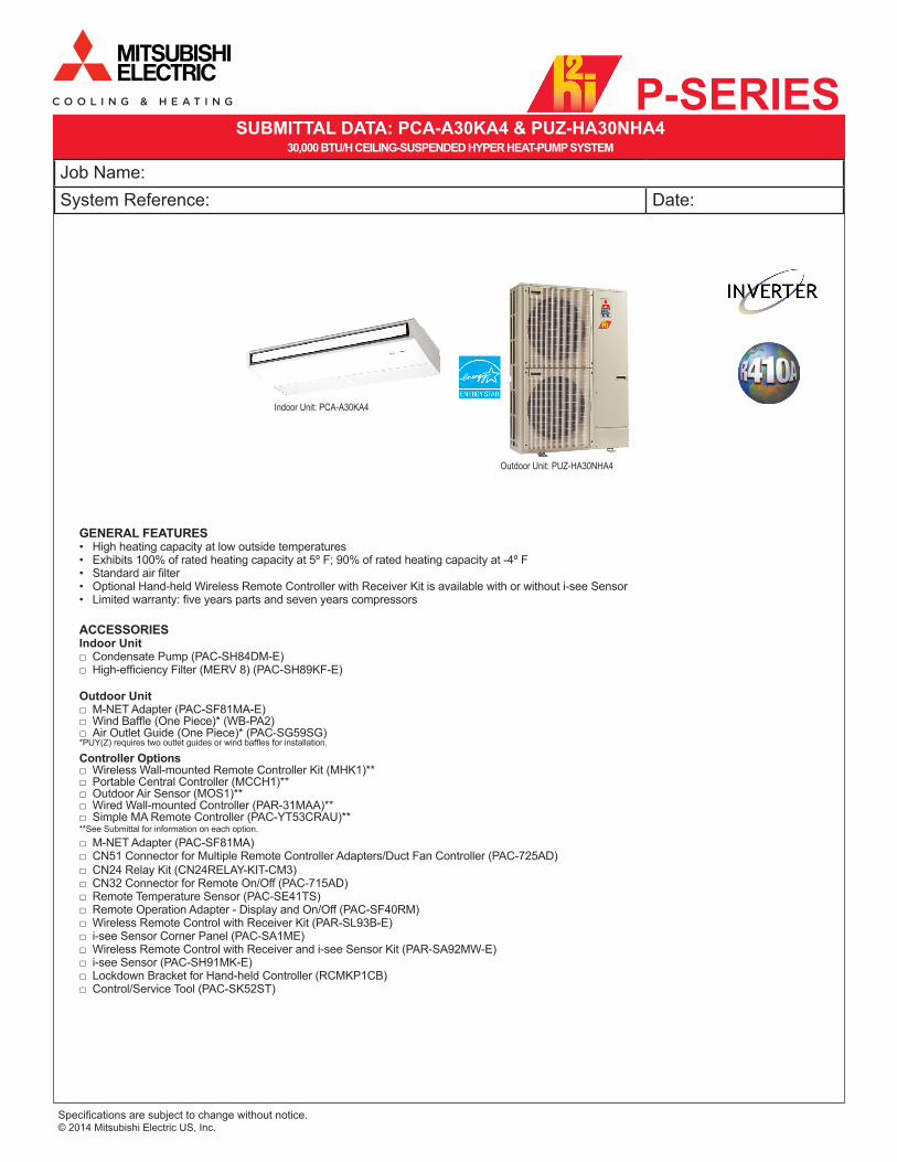
P-SERIES Specifications are subject to change without notice. © 2014 Mitsubishi Electric US, Inc. Job Name: System Reference: Date: Indoor Unit: PCA-A30KA4 SUBMITTAL DATA: PCA-A30KA4 & PUZ-HA30NHA4 30,000 BTU/H CEILING-SUSPENDED HYPER HEAT-PUMP SYSTEM ACCESSORIES Indoor Unit □ Condensate Pump (PAC-SH84DM-E) □ High-efficiency Filter (MERV 8) (PAC-SH89KF-E) Outdoor Unit □ M-NET Adapter (PAC-SF81MA-E) □ Wind Baffle (One Piece)* (WB-PA2) □ Air Outlet Guide (One Piece)* (PAC-SG59SG) *PUY(Z) requires two outlet guides or wind baffles for installation. GENERAL FEATURES • High heating capacity at low outside temperatures • Exhibits 100% of rated heating capacity at 5º F; 90% of rated heating capacity at -4º F • Standard air filter • Optional Hand-held Wireless Remote Controller with Receiver Kit is available with or without i-see Sensor • Limited warranty: five years parts and seven years compressors Controller Options □ Wireless Wall-mounted Remote Controller Kit (MHK1)** □ Portable Central Controller (MCCH1)** □ Outdoor Air Sensor (MOS1)** □ Wired Wall-mounted Controller (PAR-31MAA)** □ Simple MA Remote Controller (PAC-YT53CRAU)** **See Submittal for information on each option. □ M-NET Adapter (PAC-SF81MA) □ CN51 Connector for Multiple Remote Controller Adapters/Duct Fan Controller (PAC-725AD) □ CN24 Relay Kit (CN24RELAY-KIT-CM3) □ CN32 Connector for Remote On/Off (PAC-715AD) □ Remote Temperature Sensor (PAC-SE41TS) □ Remote Operation Adapter - Display and On/Off (PAC-SF40RM) □ Wireless Remote Control with Receiver Kit (PAR-SL93B-E) □ i-see Sensor Corner Panel (PAC-SA1ME) □ Wireless Remote Control with Receiver and i-see Sensor Kit (PAR-SA92MW-E) □ i-see Sensor (PAC-SH91MK-E) □ Lockdown Bracket for Hand-held Controller (RCMKP1CB) □ Control/Service Tool (PAC-SK52ST) Outdoor Unit: PUZ-HA30NHA4
Transcript of SUBMITTAL DATA: PCA-A30KA4 & PUZ-HA30NHA4-BS... · SUBMITTAL DATA: PCA-A30KA4 & PUZ-HA30NHA4 ......
P-SERIES
Specifications are subject to change without notice. © 2014 Mitsubishi Electric US, Inc.
Job Name:System Reference: Date:
Indoor Unit: PCA-A30KA4
SUBMITTAL DATA: PCA-A30KA4 & PUZ-HA30NHA4 30,000 BTU/H CEILING-SUSPENDED HYPER HEAT-PUMP SYSTEM
ACCESSORIES Indoor Unit
□ Condensate Pump (PAC-SH84DM-E) □ High-efficiency Filter (MERV 8) (PAC-SH89KF-E)
Outdoor Unit □ M-NET Adapter (PAC-SF81MA-E) □ Wind Baffle (One Piece)* (WB-PA2) □ Air Outlet Guide (One Piece)* (PAC-SG59SG)
*PUY(Z) requires two outlet guides or wind baffles for installation.
GENERAL FEATURES• High heating capacity at low outside temperatures• Exhibits 100% of rated heating capacity at 5º F; 90% of rated heating capacity at -4º F• Standard air filter• Optional Hand-held Wireless Remote Controller with Receiver Kit is available with or without i-see Sensor• Limited warranty: five years parts and seven years compressors
Controller Options □ Wireless Wall-mounted Remote Controller Kit (MHK1)** □ Portable Central Controller (MCCH1)** □ Outdoor Air Sensor (MOS1)** □ Wired Wall-mounted Controller (PAR-31MAA)** □ Simple MA Remote Controller (PAC-YT53CRAU)**
**See Submittal for information on each option.
□ M-NET Adapter (PAC-SF81MA) □ CN51 Connector for Multiple Remote Controller Adapters/Duct Fan Controller (PAC-725AD) □ CN24 Relay Kit (CN24RELAY-KIT-CM3) □ CN32 Connector for Remote On/Off (PAC-715AD) □ Remote Temperature Sensor (PAC-SE41TS) □ Remote Operation Adapter - Display and On/Off (PAC-SF40RM) □ Wireless Remote Control with Receiver Kit (PAR-SL93B-E) □ i-see Sensor Corner Panel (PAC-SA1ME) □ Wireless Remote Control with Receiver and i-see Sensor Kit (PAR-SA92MW-E) □ i-see Sensor (PAC-SH91MK-E) □ Lockdown Bracket for Hand-held Controller (RCMKP1CB) □ Control/Service Tool (PAC-SK52ST)
Outdoor Unit: PUZ-HA30NHA4

Specifications are subject to change without notice. © 2014 Mitsubishi Electric US, Inc.
SPECIFICATIONS: PCA-A30KA4 & PUZ-HA30NHA4
ELECTRICAL REQUIREMENTSPower Supply . . . . . . . . . . . . . . . . . . . . 208 / 230V, 1-Phase, 60 HzBreaker Size. . . . . . . . . . . . . . . . . . . . . . . . . . . . . . . . . . . . . . . .30 AVoltageIndoor - Outdoor S1-S2 . . . . . . . . . . . . . . . . . . . . . . AC 208 / 230VIndoor - Outdoor S2-S3 . . . . . . . . . . . . . . . . . . . . . . . . . . .DC ±24VIndoor - Remote Controller . . . . . . . . . . . . . . . . . . . . . MKH1 DC 3V
PAR-21MAAU DC 12VPAR-FL32MA DC 3V
OPERATING RANGEIndoor Intake Air Temp. Outdoor Intake Air Temp.
CoolingMaximum 90º F (32º C) DB
73º F (23º C) WB 115º F (46º C) DB
Minimum 66º F (19º C) DB 59º F (15º C) WB 0º F** (-18º C) DB
HeatingMaximum 83º F (28º C) DB 70º F (21º C) DB
59º F (15º C) WB
Minimum 63º F (17º C) DB -13º F (-25º C) DB -13º F (-25º C) WB
Note: With optional wind baffle accessory installed. If not installed, the minimum temperature will be 23º F (-5º C) DB.
CoolingRated Capacity* . . . . . . . . . . . . . . . . . . . . . . . . . . . . . .30,000 Btu/hMinimum Capacity . . . . . . . . . . . . . . . . . . . . . . . . . . . .18,000 Btu/hSEER . . . . . . . . . . . . . . . . . . . . . . . . . . . . . . . . . . . . . .16.1 Btu/h/WTotal Input . . . . . . . . . . . . . . . . . . . . . . . . . . . . . . . . . . . . . ..2,480 WHeating at 47°FRated Capacity* . . . . . . . . . . . . . . . . . . . . . . . . . . . . . .32,000 Btu/hMinimum Capacity . . . . . . . . . . . . . . . . . . . . . . . . . . . .18,000 Btu/hHSPF (IV) . . . . . . . . . . . . . . . . . . . . . . . . . . . . . . . . . . . .9.3 Btu/h/WTotal Input . . . . . . . . . . . . . . . . . . . . . . . . . . . . . . . . . . . . . ..2,990 WHeating at 17°FRated Capacity* . . . . . . . . . . . . . . . . . . . . . . . . . . . . . .19,000 Btu/hRated Total Input . . . . . . . . . . . . . . . . . . . . . . . . . . . . . . . ..2,830 WMaximum Capacity** . . . . . . . . . . . . . . . . . . . . . . . . . .32,000 Btu/hTotal Input . . . . . . . . . . . . . . . . . . . . . . . . . . . . . . . . . . . . . ..5,830 W
Heating at 5°FMaximum Capacity** . . . . . . . . . . . . . . . . . . . . . . . . . .32,000 Btu/hTotal Input . . . . . . . . . . . . . . . . . . . . . . . . . . . . . . . . . . . . . ..5,830 W
* Rating Conditions per AHRI Standard Cooling | Indoor: 80º F (27º C) DB / 67º F (19º C) WB Cooling | Outdoor: 95º F (35º C) DB / 75º F (24º C) WBHeating at 47º F | Indoor: 70º F (21º C) DB / 60º F (16º C) WB Heating at 47º F | Outdoor: 47º F (8º C) DB / 43º F (6º C) WB Heating at 17º F | Indoor: 70º F (21º C) DB / 60º F (16º C) WB Heating at 17º F | Outdoor: 17º F (-8º C) DB / 15º F (-9º C) WB**Heating at 5º F | Indoor: 70º F (21º C) DB / 60º F (16º C) WB **Heating at 5º F | Outdoor: 5º F (-15º C) DB / 5º F (-15º C) WB
** Maximum Capacity is at full speed and performance for INVERTER-driven System.
INDOOR UNITMCA . . . . . . . . . . . . . . . . . . . . . . . . . . . . . . . . . . . . . . . . . . . . . . 1 A Blower Motor (ECM) . . . . . . . . . . . . . . . . . . . . . . . . . . . 0.54 F.L.A.Blower Motor Output. . . . . . . . . . . . . . . . . . . . . . . . . . . . . . . . .95 WAirflow (Lo - M1 - M2 - Hi) . . . . . . . 565 - 600 - 635 - 705 Dry CFM 530 - 565 - 600 - 670 Wet CFMSound Pressure Level (Lo - M1 - M2 - Hi) . . 35 - 37 - 39 - 41 dB(A)DIMENSIONS UNIT INCHES / MM PANEL INCHES / MMW 50-3/8 / 1,280 37-3/8 / 950D 26-3/4 / 680 37-3/8 / 950H 9-1/16 / 230 1-3/8 / 35
Weight . . . . . . . . . . . . . . . . . . . . . . . . . . . . . . . . . . . .71 lbs. / 32 kgExternal Finish . . . . . . . . . . . . . . . . . . . . . Munsell No. 6.4 8.9 / 0.4Field Drainpipe Size O.D. . . . . . . . . . . . . . . . . . . . . 1-1/32” / 26 mm
Outdoor UnitCompressor . . . . . . . . . . . . . . . . . . . . . . . DC Inverter-driven ScrollMCA . . . . . . . . . . . . . . . . . . . . . . . . . . . . . . . . . . . . . . . . . . . . . . . .28Fan Motor (ECM) . . . . . . . . . . . . . . . . . . . . . . . . . . .0.4 + 0.4 F.L.A.Sound Pressure Level Cooling . . . . . . . . . . . . . . . . . . . . . . . . . . . . . . . . . . . . . . 52 dB(A) Heating . . . . . . . . . . . . . . . . . . . . . . . . . . . . . . . . . . . . . . 53 dB(A) DIMENSIONS INCHES / MMW 37-3/8 / 950D 13 + 1-3/16 / 330 + 30H 53-1/8 / 1,350
Weight . . . . . . . . . . . . . . . . . . . . . . . . . . . . . . . . . .265 lbs. / 120 kgExternal Finish . . . . . . . . . . . . . . . . . . . . . .Munsell No. 3Y 7.8 / 1.1Refrigerant Type . . . . . . . . . . . . . . . . . . . . . . . . . . . . . . . . . . R410ARefrigerant Pipe Size O.D. Gas Side . . . . . . . . . . . . . . . . . . . . . . . . . . . . . . . .5/8” / 15.88 mm Liquid Side. . . . . . . . . . . . . . . . . . . . . . . . . . . . . . . .3/8” / 9.52 mmMax. Refrigerant Pipe Length. . . . . . . . . . . . . . . . . . . . . 245’ / 75 mMax. Refrigerant Pipe Height Difference . . . . . . . . . . . . 100’ / 30 mConnection Method . . . . . . . . . . . . . . . . . . . . . . . . . . . . . . . .Flared
Notes:

Specifications are subject to change without notice. © 2014 Mitsubishi Electric US, Inc.
DIMENSIONS: PCA-A30KA4
[]
"
vent
ilatio
n ai
r(
)
[]
"
[FR
ON
T V
IEW
LOO
KIN
G T
HR
OU
GH
TH
E U
NIT
]
[BA
CK
VIE
W]
If th
e pi
ping
is in
stal
led
in th
e ba
ckof
the
unit,
rem
ove
the
shad
ed p
ortio
ns fr
omth
e co
mpo
nent
at r
ight
. The
n, re
inst
all t
heco
mpo
nent
in it
s or
igin
al p
ositi
on (t
he h
eat
exch
ange
r mig
ht b
e cl
ogge
d be
ause
of d
ust.

1340 Satellite BoulevardSuwanee, GA 30024Toll Free: 800-433-4822www.mehvac.com
Specifications are subject to change without notice. © 2014 Mitsubishi Electric US, Inc.
FORM# PCA-A30KA4 / PUZ-HA30NHA4 - 201409
DIMENSIONS: PUZ-HA30NHA4
Unit : mm<inch>
Min
. 100
0mm
<39-
3/8>
Min
. 150
mm
<5-2
9/32
>
Min
. 10m
m<3
/8>
Min
. 10m
m<3
/8>
FRE
E
<Fou
ndat
ion
bolt
heig
ht>
FOUN
DATI
ON
Ser
vice
spa
ce
Term
inal
Blo
ckLe
ft···P
ower
sup
ply
wirin
gRi
ght··
··Ind
oor/O
utdo
or w
iring
Ear
th te
rmin
al
Ser
vice
pan
el
Han
dle
1 2
23<29/32>
1076<42-3/8>
* 1 447<17-19/32>
* 1 443<17-7/16>
Han
dle
Fron
t pip
ing
cove
r
Rea
r pip
ing
cove
r
Air D
ischa
rge
Rear
Air
Inta
ke
Side
Air
Inta
ke
31<1-7/32>
145
<5-2
3/32>
145
<5-2
3/32>
220
<8-2
1/32>
30<1
-3/1
6>14
5<5
-23/3
2>
81<3-3/16>219<8-5/8>
71<2-13/16>
71<2
-13/
16>
Bot
tom
pip
ing
hole
(Kno
ckou
t)
Dra
in h
ole
5-33
<1-5
/16>
Han
dle
Sid
e A
ir In
take
Air
inta
ke
Rea
r Air
Inta
ke
Han
dle
Han
dle
40<1
-9/1
6>
74<2
-19/
32>
Whe
n in
stal
ling
the
cond
uit.
Set
the
atta
chm
ent t
o th
e in
ner s
ide
of e
ach
pane
l.
2-22
.2<7
/8>
1/2
Con
duit
atta
chm
ent
45<1
-25/3
2>40
<1-9
/16>
65<2
-9/1
6>92
<3-5
/8>
27<1-1/16>55<2-3/16>
23<29/32>73<2-7/8>63<2-1/2>
Rea
r pip
ing
hole
(Kno
ckou
t)
Rea
r tru
nkin
g ho
le(K
nock
out)
Cond
uit ho
le (2-
27<1
-1/16
>Kno
ckou
t)
92<3
-5/8
>
19<3
/4>55
<2-3
/16>
92<3
-5/8
>
75<2
-31/3
2>40
<1-9
/16>
73<2-7/8>63<2-1/2>
23<29/32>27<1-1/16>92<3-5/8>R
ight
pip
ing
hole
(Kno
ckou
t)R
ight
trun
king
hol
e(K
nock
out)
Con
duit
hole
(2
-27
<1-1
/16>
Kno
ckou
t)
92<3
-5/8
>
92<3
-5/8
>65
<2-9
/16>
45<1
-25/
32>
40<1
-9/1
6>
27<1-1/16>55<2-3/16>
23<29/32>73<2-7/8>
63<2-1/2>
Fron
t pip
ing
hole
(Kno
ckou
t)
Fron
t tru
nkin
g ho
le(K
nock
out)
Con
duit
hole
(2
-27
<1-1
/16>
Kno
ckou
t)
92
<3-5
/8>
371<14-19/32>
330<13> 30<1-3/16>
175<
6-7/
8>60
0<23
-5/8
>17
5<6-
7/8> 42
<1-2
1/32
>66
<2-5
/8>
950<
37-1
3/32
>
322<
12-1
1/16
>
1350<53-5/32>
635<25>
19<3/4>417<16-13/32>
370<14-9/16>
2-U
Sha
ped
notc
hed
hole
(Fou
ndat
ion
Bol
t M10
<W3/
8>)
56<2-7/32>
28<1-3/32>
53<2-3/32>
45<1-25/32>
2-12
36 O
val h
ole
(Fou
ndat
ion
Bol
t M10
<W3/
8>)
····R
efrig
eran
t GAS
pipe
conn
ction
(FLA
RE)
15.8
8<5/
8>···
·Ref
riger
ant L
IQUI
D pip
e co
nnec
tion
(FLA
RE)
9.5
2<3/
8>*1
····I
ndica
tion
of S
TOP
VALV
E co
nnec
tion
locat
ion.
Exam
ple
of N
otes
1 FRE
E SPA
CE (A
round
the u
nit)
2 SE
RVIC
E SP
ACE
3 FOU
NDAT
ION
BOLT
S4 P
IPING
-WIR
ING
DIRE
CTIO
NS
Pipi
ng K
nock
out H
ole
Deta
ils
The
diag
ram
bel
ow s
hows
aba
sic e
xam
ple.
Expl
antio
n of
par
ticul
ar d
etai
ls ar
egi
ven
in th
e in
stal
latio
n m
anua
ls et
c.
Dim
ensio
ns o
f spa
ce n
eede
dfo
r ser
vice
acce
ss a
resh
own
in th
e be
low
diag
ram
.
Plea
se s
ecur
e th
e un
it fir
mly
with
4 fo
unda
tion
(M10
<W3/
8>)
bolts
. (Bo
lts a
nd w
ashe
rs m
ust
be p
urch
ased
loca
lly.)
Pip
ing
and
wiri
ng c
onne
ctio
nsca
n be
mad
e fro
m 4
dire
ctio
ns:
front
, rig
ht, r
ear a
nd b
elow
.
Min
.10
mm
<3/8
>
Min.500mm<19-11/16>
Min.
500m
m<1
9-11/1
6>
Min.150mm<5-29/32>
Min.30mm<1-3/16>


![[Model Name] [Service Ref.] PUZ-ZM35VKA PUZ-ZM50VKA PUZ ... · puz-zm60vha(-et) puz-zm71vha(-et) symbol 1 g r01 e72 221fan motor 1 1 mf1 2 g r01 e12 115propeller fan 1 1 3 g r01 e09](https://static.fdocuments.in/doc/165x107/5e1925b50df5c673806c1e57/model-name-service-ref-puz-zm35vka-puz-zm50vka-puz-puz-zm60vha-et-puz-zm71vha-et.jpg)