
Sub Metering Technology - SpeedRead Tech
97
1 Sub Metering Technology ®SpeedRead Technologies 3901 West 86 th Street • Suite 410 Indianapolis, Indiana 46268 Phone 317.824.45444 • Fax 317.824.4547 Training and Installation Manual Version 08082007-1A
Transcript of Sub Metering Technology - SpeedRead Tech

1
Sub Metering Technology
®SpeedRead Technologies 3901 West 86th Street • Suite 410
Indianapolis, Indiana 46268 Phone 317.824.45444 • Fax 317.824.4547
Training and Installation Manual
Version 08082007-1A

2

3
PART 1 SYSTEM OVERVIEW
SYSTEM COMPONENTS

4
1 SYSTEM OVERVIEW
SpeedRead System – Background
The SpeedRead System was designed to provide a tool for water consumption management. The system has been enhanced to now include AMR for electric and gas metering, all of which can be read and monitored through the same equipment. The system is designed to collect remote readings of water, electric and gas meters, and then transfer the data collected to a control center where the data is processed. The system is wireless using Radio Frequency (RF) transmissions to send the data to the collection unit. It is designed for operation in an urban environment where meters are installed. Typical meter installation sites include:
Multi Family apartment buildings Single Family homes Irrigation systems Commercial and Industrial buildings Pit set meters The system comprises four main components: The Speednet Software Family, including SpeedNet Premium, SpeedNet Standard and SpeedNet Field version Regional Concentrator (CML) data collection unit. SpeedRead Repeater STx SpeedRead Transmitters The system is a licensed frequency that uses the 450 through 470 MHz Band. transmitting at 60m watts. This system allows for a large range of installations from utility markets to multi family installations. 1.2 SYSTEM OVERVIEW
System General Description
The system is a wireless (RF) fixed network system. Fixed network meaning the system is designed to be installed in one location and monitor that location or the surrounding areas. It collects and stores CURRENT data within its memory for retrieval at a later date by the RBC or collection facility. The SpeedRead system uses a Licensed Radio Frequency. The frequency is determined by an independent organization. The steps involved are simple and the procedure is typically finished

5
in 10 to 14 working days. The steps are as follows. 1. An application is applied for by SpeedRead to determine if a standard frequency is available. This requires the installer to provide SpeedRead with:
a. The Federal Tax ID number of the Customer. b. The actual street address or central point where the system will be installed c. The customers name
2. The application is processed and the area in question is evaluated for available frequency. 3. If the basic frequency is not available a search parameter is initiated until a suitable frequency is found. 4. Once the frequency is established then an application is applied for that frequency. 5. Once basic approval is granted, usually within 10 – 14 working days then installation can start.

6
PART 2 SYSTEM OVERVIEW
SYSTEM COMPONENTS
7
2.1 SYSTEM COMPONENTS –REGIONAL CONCENTRATOR
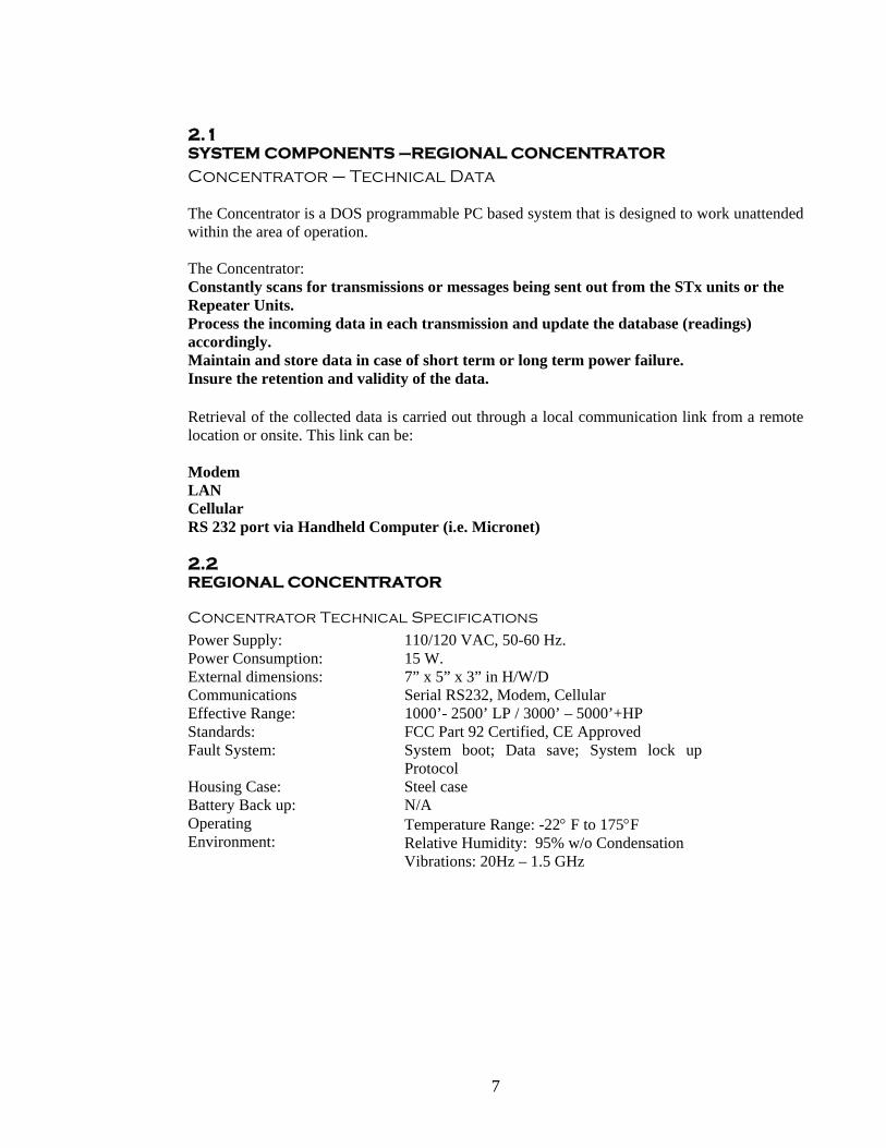
Concentrator – Technical Data The Concentrator is a DOS programmable PC based system that is designed to work unattended within the area of operation. The Concentrator: Constantly scans for transmissions or messages being sent out from the STx units or the Repeater Units. Process the incoming data in each transmission and update the database (readings) accordingly. Maintain and store data in case of short term or long term power failure. Insure the retention and validity of the data. Retrieval of the collected data is carried out through a local communication link from a remote location or onsite. This link can be: Modem LAN Cellular RS 232 port via Handheld Computer (i.e. Micronet) 2.2 REGIONAL CONCENTRATOR
Concentrator Technical Specifications
Power Supply: 110/120 VAC, 50-60 Hz. Power Consumption: 15 W. External dimensions: 7” x 5” x 3” in H/W/D Communications Serial RS232, Modem, Cellular Effective Range: 1000’- 2500’ LP / 3000’ – 5000’+HP Standards: FCC Part 92 Certified, CE Approved Fault System: System boot; Data save; System lock up
Protocol Housing Case: Steel case Battery Back up: N/A Operating Environment:
Temperature Range: -22° F to 175°F Relative Humidity: 95% w/o Condensation Vibrations: 20Hz – 1.5 GHz
8
2.3 REGIONAL CONCENTRATOR
Concentrator - Programmable Parameters
The Concentrator must be programmed in advance or in the field during installation to receive and store the collected data. Parameters that are programmable by the field technician are: Number of AMR or meters installed in the system. Meter Readings. STx Transmitter Serial Numbers. Number of meters attached to the STx Transmitter. Meter Multiplier Setting Optional Programmable settings: Number of pulses collected Number of receptions received from transmitter 2.4 REGIONAL CONCENTRATOR
The Concentrator Operating System
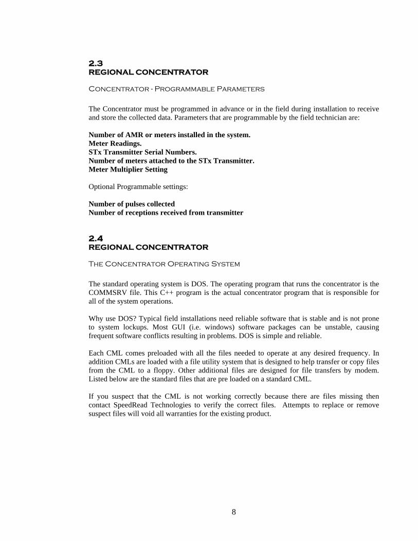
The standard operating system is DOS. The operating program that runs the concentrator is the COMMSRV file. This C++ program is the actual concentrator program that is responsible for all of the system operations. Why use DOS? Typical field installations need reliable software that is stable and is not prone to system lockups. Most GUI (i.e. windows) software packages can be unstable, causing frequent software conflicts resulting in problems. DOS is simple and reliable. Each CML comes preloaded with all the files needed to operate at any desired frequency. In addition CMLs are loaded with a file utility system that is designed to help transfer or copy files from the CML to a floppy. Other additional files are designed for file transfers by modem. Listed below are the standard files that are pre loaded on a standard CML. If you suspect that the CML is not working correctly because there are files missing then contact SpeedRead Technologies to verify the correct files. Attempts to replace or remove suspect files will void all warranties for the existing product.

9
2.4.1 Commsrv.exe
As listed above, the operating systems main software is COMMSRV.EXE. This proprietary software functions as the link between the Transmitters to CML to User. Commsrv is designed to evaluate incoming STx transmissions or data and perform the following functions:
Update reading data if it has increased Update receptions sources Updates Transmitter Events Codes and Reading Events Updates CML Events Perform data saves
Commsrv is designed with a fail-safe feature that allows the system to recover from a catastrophic failure of the database. This feature is designed to bring the system back on line so that an external connection would allow the user to restore the systems data. This feature works along side the watchdog software. Although this feature is designed as a fail-safe feature it has a fault that can cause problems. The system feature works as such:
1. The data gets corrupt because of a failed download or external source. 2. The System attempts to load the data and is unsuccessful. 3. As the data is loaded it causes the software to lock up. 4. After approximately 5 minutes the Watch Dog software forces a reboot of the system. 5. Steps 1 through 4 are repeated several times, each time the system fails to reload the
data. 6. After approximately 5 attempts Commsrv will rename the existing Data file to
“SAVA.BAD” and create a new database to bring the system back on line.
As can be seen by this description of the software, it is very reliable in attempting to maintain a link between CML and user. This feature although extremely beneficial, can be initiated by the user turning off power to the system repeatedly with in a 5 minute period. To prevent the above problem from being caused inadvertently, the field technician should be well trained on this scenario so that attempts to reset the data collector do not cause loss of collector data.
10
2.5 REGIONAL CONCENTRATOR
The Concentrator Operating System – Overview
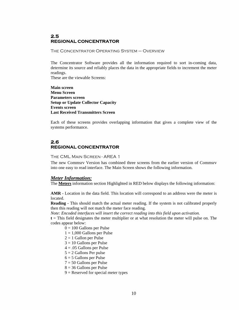
The Concentrator Software provides all the information required to sort in-coming data, determine its source and reliably places the data in the appropriate fields to increment the meter readings. These are the viewable Screens: Main screen Menu Screen Parameters screen Setup or Update Collector Capacity Events screen Last Received Transmitters Screen Each of these screens provides overlapping information that gives a complete view of the systems performance. 2.6 REGIONAL CONCENTRATOR
The CML Main Screen - AREA 1 The new Commsrv Version has combined three screens from the earlier version of Commsrv into one easy to read interface. The Main Screen shows the following information. Meter Information: The Meters information section Highlighted in RED below displays the following information: AMR - Location in the data field. This location will correspond to an address were the meter is located. Reading - This should match the actual meter reading. If the system is not calibrated properly then this reading will not match the meter face reading. Note: Encoded interfaces will insert the correct reading into this field upon activation. t = This field designates the meter multiplier or at what resolution the meter will pulse on. The codes appear below: 0 = 100 Gallons per Pulse 1 = 1,000 Gallons per Pulse 2 = 1 Gallon per Pulse 3 = 10 Gallons per Pulse 4 = .05 Gallons per Pulse 5 = 2 Gallons Per pulse 6 = 5 Gallons per Pulse 7 = 50 Gallons per Pulse 8 = 36 Gallons per Pulse 9 = Reserved for special meter types

11
Counter - Accumulated pulses collected by STx unit. (Encoded Meters Show No Pulses) Counter – Numbers of Pulses collected by STx unit LE – Leakage Status and Error Status Codes. See Addendum F. The gray highlighted areas on the lower part of the Meters section are the function keys the user will press to access the data fields: F2 – Enter or Update Meter Readings F3 – Update the Meter Resolution / or multiplier ID F4 – Update the Counter or Pulses
Illustration 2.6 Concentrator Main Screen with Meters Section outlined.

12
2.7 REGIONAL CONCENTRATOR
The CML Main Screen - AREA 2 – Transmitter Data Section
Transmitter Information: This area details all information about transmitters, including reception sources. Some of this data (STX Serial # etc.) can be changed by the installer; the other data will change during normal system operation. TX ID = Transmitter Serial Number, this 5 digit number is unique to each transmitter. n = Number of outputs (meters) connected to the STx unit. RxCNT = Number of transmissions collected or received since STx was first installed. TxCNT – Number of transmissions made by the transmitter since installed C124345678 – Reception source of the last transmission, C= Collector, 1 to 8 = Repeater ID Date Time – Time stamp and date of the last successful transmitter reception. This date is taken from the Collector System Date and Time. In addition to these areas, the divider between Area 1 and 2 includes the section for transmitter reception source and error codes (See Illustration 2.7). This area is updated during normal operations as data is received from incoming transmissions. The gray highlighted areas on the lower part of the Transmitters section are the function keys the user will press to access the data fields: F5 – Enter or Update Transmitters Serial Numbers F3 – Enter the number of meters that will be attached to the transmitter F4 – Update the number of Received transmissions
Illustration 2.7 Concentrator screen showing the transmitter data outlined.
13
2.8 REGIONAL CONCENTRATOR
The CML Main Screen - AREA 3 – Message Area Section
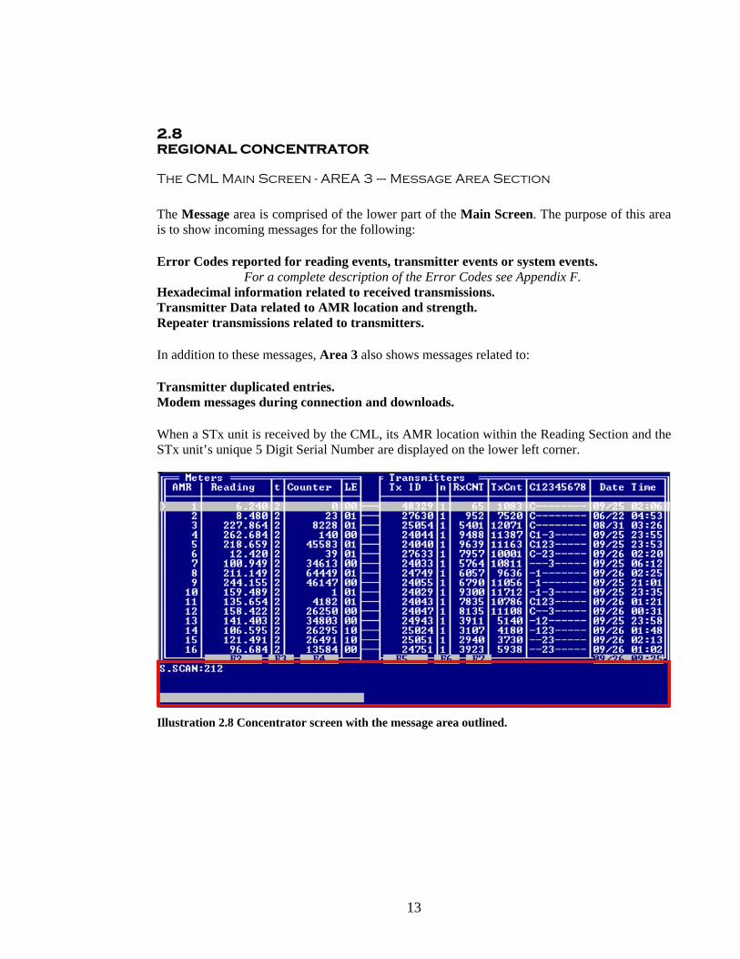
The Message area is comprised of the lower part of the Main Screen. The purpose of this area is to show incoming messages for the following: Error Codes reported for reading events, transmitter events or system events.
For a complete description of the Error Codes see Appendix F. Hexadecimal information related to received transmissions. Transmitter Data related to AMR location and strength. Repeater transmissions related to transmitters. In addition to these messages, Area 3 also shows messages related to: Transmitter duplicated entries. Modem messages during connection and downloads. When a STx unit is received by the CML, its AMR location within the Reading Section and the STx unit’s unique 5 Digit Serial Number are displayed on the lower left corner.
Illustration 2.8 Concentrator screen with the message area outlined.

14
2.9 REGIONAL CONCENTRATOR
The CML – Menu Screen
Press F1 to advance to the Menu screen. This version of Commsrv has a menu screen that shows the keys required to access other screen areas to update the collector. By pressing F1 at the main screen the user will see the screen shown below. The area marked in the RED rectangle is the menu key descriptions. Pressing these key combinations from the Main Screen will access the listed screens. Pressing any other key will return you to the Main screen. The table to the right describes the Meter Resolutions for each meter multiplier. This allows easy reference for the installer.
Illustration 2.9 – The Menu Screen
Press ESC to return to the Main screen

15
2.10 REGIONAL CONCENTRATOR
The CML – Events log Screen
Press TAB to advance to the Events Log screen. The concentrator software is designed to log events that affect the performance and changes made to the concentrator during normal operation. These events may give some insight to problems associated with power outages and or updates to the system. Event Number and Date: This column details the events that have been recorded on the system using an Event Code, and has a date and time stamp that explains the event. Event Code and Description: This column explains the event. Sys. Info: This column contains the following system information.
SCAN – This number will increment every second the system is powered on and is an indicator that the system software (COMMSRV) is running. The number will reset upon a restart of the Commsrv software. Max AMR – This shows the maximum number of meters that can currently be programmed in the system. The maximum number of AMR's is related to the number of meters set in the Update Collector Capacity screen detailed later. Vers – This is the current version number of the OS (Commsrv) software. Log Event – This shows the number of events recorded in the log file. Com – This shows the current COM settings for the Receiver and the Modem. Please see the Parameters Screen info on the correct settings.
Event Number date and time Event Code and Description Sys. Info 1: 17:08:2001 15:48:19 1 Restart 2: 18:08.2001 14:20:09 2 Electricity Interruption SCAN :230 3: 18:08.2001 14:32:38 3 Low Battery Voltage Max AMR: 320 4: 18:08.2001 14:41:06 4 Power Restored Vers : 2.02 5: 18:08.2001 14:41:06 5 Initiated Exit Log Event: 7 6: 18:08.2001 15:44:08 6 Not In Use(Municipality) Com: 9 4 7: 18:08.2001 15:56:09 7 Storage of Data
Illustration 2.10: This illustration shows an example of all the events codes that are logged in the file.
16
2.11 REGIONAL CONCENTRATOR
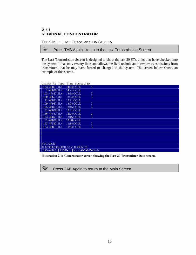
The CML – Last Transmission Screen
Press TAB Again - to go to the Last Transmission Screen The Last Transmission Screen is designed to show the last 20 STx units that have checked into the system. It has only twenty lines and allows the field technician to review transmissions from transmitters that he may have forced or changed in the system. The screen below shows an example of this screen. Last Stx Rx Type Time Source of Rx [ 123- 48861] IL+ 14:24 COLL 3 [ 1- 48898] IL+ 14:21 COLL [ 103- 47887] IL+ 13:34 COLL 2 [ 120- 48661] IL+ 13:24 COLL 3 [ 21- 48891] IL+ 13:21 COLL [ 109- 47987] IL+ 13:04 COLL 2 [ 105- 48861] IL+ 12:45 COLL 3 [ 91- 48888] IL+ 12:31 COLL [ 156- 47857] IL+ 12:24 COLL 2 [ 133- 48801] IL+ 12:16 COLL 3 [ 31- 44898] IL+ 12:08 COLL [ 193- 47547] IL+ 11:14 COLL 2 [ 123- 48861] IL+ 11:04 COLL 3 R.SCAN:63 3e be 00 C9 00 00 01 5c 5b fc 00 22 78 [ 123- 48861] [ RPTR- 3+] IC1+ ANT-0 PWR-5a
Illustration 2.11 Concentrator screen showing the Last 20 Transmitter Data screen.
Press TAB Again to return to the Main Screen
17
2.12 REGIONAL CONCENTRATOR
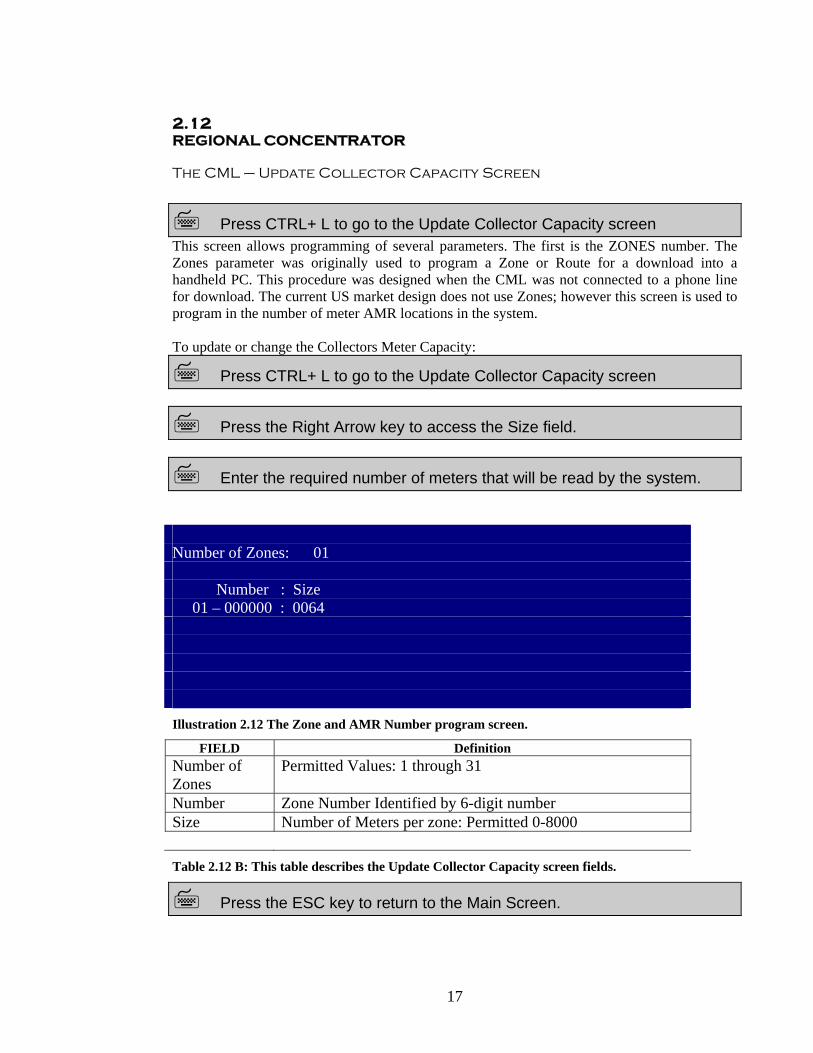
The CML – Update Collector Capacity Screen
Press CTRL+ L to go to the Update Collector Capacity screen This screen allows programming of several parameters. The first is the ZONES number. The Zones parameter was originally used to program a Zone or Route for a download into a handheld PC. This procedure was designed when the CML was not connected to a phone line for download. The current US market design does not use Zones; however this screen is used to program in the number of meter AMR locations in the system. To update or change the Collectors Meter Capacity:
Press CTRL+ L to go to the Update Collector Capacity screen
Press the Right Arrow key to access the Size field.
Enter the required number of meters that will be read by the system. Number of Zones: 01 Number : Size 01 – 000000 : 0064 Illustration 2.12 The Zone and AMR Number program screen.
FIELD Definition Number of Zones
Permitted Values: 1 through 31
Number Zone Number Identified by 6-digit number Size Number of Meters per zone: Permitted 0-8000 Table 2.12 B: This table describes the Update Collector Capacity screen fields.
Press the ESC key to return to the Main Screen.

18
2.12 REGIONAL CONCENTRATOR
The CML – The System Parameters Screen
Press the CTRL+P keys to advance to the Parameters Screen.
WARNING: Making changes to the Parameters Screen may make the system unstable and/or cause the system to fail. The Systems Parameters screen allows access to the default system settings if they should need to be changed or altered. The settings are set as default and under most circumstances should never need to be changed. If Parameter Setting changes are needed, you should contact SpeedRead Technologies for the correct settings or optional settings.
The following are the only items that should be changed in the Parameters Screen. The Com Setting for Com 1 and Com 2 Modem Baud Rate - Default setting is 2400, Maximum Setting is 115200 The other setting definitions are as follows: COM DATA Com 1: Used for the communication setting for the Receiver Unit. Com 2: Used for the communication setting for the Modem
Illustration 2.12.1: The Parameters Screen

19
MODEM DATA Baud : Modems Baud or data transfer setting, 115200 Rings : Determines how many rings before the modem answers, 00 Init string : Modem command to initialize the modem, atm0 IRQ : PC Interrupt Request Setting, 5 GSM : Setting required for GSM or cellular modem, 0 GENERAL DATA Wait : Time in seconds to wait for input in a data field. Soft Watchdog : The setting to turn off or on the system Software Watchdog software, this setting allows the system to reset if the software or other incident causes the system to hang. Backup Time : The default setting for backup to the History Backup file, the default setting is 24, for 12:00 AM Save Hour : The default setting for the time the system backup of the sava.dat file. This is not the same as the History Backup setting. Max Files : The default number of days the History File will be written to, before the system will begin to overwrite each day, 90 is the default number of days the system will save to the history file. This setting is also dependent upon the number of meters and transmitters that are programmed into the system. Please contact SpeedRead if this setting needs to be changed.
20
3. SYSTEM COMPONENTS-REPEATERS REPEATERS - Repeater Description and Overview The SpeedRead Repeater is the second Component of the SpeedRead System. Repeaters are designed to add a level of redundancy to the system, and they also allow the range of coverage of the entire system in an overlapping pattern. Repeaters are non-dependent of other repeaters. They interact as separate components within the system. This functionality allows them to work even if another repeater in the same area fails. Repeaters are also NON-SYSTEM dependent, however they are frequency dependent. Thus any repeater of the same frequency is capable of talking to any CML of the same frequency within its field of coverage. This design does not require the repeaters to be programmed into the system, once mounted and powered up they will begin to function immediately. The repeaters perform their functions as follows: Scan for transmissions being sent by the STx Transmitters. Validate the transmission as a qualified transmission. Transmit the data to the CML. Since they are independent of the other repeaters they can be mounted in an overlaying pattern that creates redundant receptions from multiple transmitters. This operation is designed to reduce multiple receptions by sequentially numbering the repeaters that are to be installed. Typical sites would have any number of repeaters with a number system starting at 1 and up to 8. This numbered system is in fact the send receive delay that is built into the repeaters. Each repeater will receive then hold for time delay equal to its Designator Number. Thus a #1 Repeater will receive a transmission and hold it for 1 ms before it transmits it to the CML. A Repeater # 4 would hold it for 4 ms. This delay will show up in the system as a number under reception source. This allows the installer to see verify that each repeater is checking in as designed.

21
3.2 REPEATERS
Repeater Technical Specifications
Power Supply: 12 VDC, 120 ma (Solar Option Available) Power Consumption: 15 W. External dimensions: 6 x 4 x 3 in. (H/W/D) Weight 2.3 lbs.
Antenna 24” W x 12” H Effective Range: 1000’- 2500’ LP / 3000’ – 5000’+HP Standards: FCC Part 92 Certified, CE Approved Housing Case: Plastic sealable case Operating Environment:
Temperature Range: -22° to 175° F Relative Humidity: 90% w/o condensation
Table 3-2: Repeater Technical Specification

22
4. SYSTEM COMPONENTS - TRANSMITTERS
Transmitter Technical Specifications
The SpeedRead transmitters commonly known as STx units are the interface between Utility Meter and the Operating System. They are an autonomous transmitter unit with an internal, long life battery. The unit is installed in proximity to the meter to be read or can be installed up to 120’ from the meter using 22 AWG, 100% Shielded Wire. The basic unit functions include: For Standard pulse STX it will constantly sample the meter switch checking for a pulse. For Active Pulse Meters it will wait for the Pulse Output Encoded STx units will periodically check the meter head for reads. Store all pulses collected from the meter. (Active and Passive pulse only) Store Alarms or Errors in their internal memory Track collected pulses and determine if consumption criteria is met. Tracks the time from the last transmission and determine if the set time criteria has been met. Transmit the collected data via RF, on a timely interval based on: Time Data collected Tamper Switch Forced Transmissions The STx uses one of the pre designated frequencies to send their data. Since their range is limited they work in parallel with the Repeaters or directly with the CML. There are two major circuits:
The digital circuit The RF Circuit
The Digital Circuit Section performs the following functions:
Counts the serial input pulses from the meter source. Stores the data including alarms. Passes collected data to the RF section for transmission.
The RF Circuit is designed to perform as follows: The STx is designed to gather data for several hours (typically 4 hours) before sending its collected data to the CML. If for any reason the meter should advance by more than a preset value in a short period or it detects an alarm condition, then it will transmit a single message to the CML.

23
Once an alarm condition is met then every message sent from that particular STx would include the alarm as long as the alarm condition exists, or the alarm is cleared by the control software.

24
Power Supply: 3.6 Lithium battery, 10 year rated life Power Output: 60 mWatts External dimensions: 4.4.” x 2.4” x 1.2” (H/W/D) Communications RF - 450 through 470 MHz Effective Range: 500’ LP / 5000’ HP Maximum Wire Length 120’ Meter to Transmitter Required Wire Type 22 AWG, 100% Shielded Standards: FCC Part 92 Certified Housing Case: Extruded Plastic Sealable Case Operating Environment:
Temperature Range: -22° to 175° F Relative Humidity: 90% w/o condensation
Table 4-1: Table of Transmitter Specs
4.1 Types of Transmitters There are currently several types or models of transmitters that are available for installations, these models are defined by the type and style of utility style meter the transmitter will be interfaced with. In most cases the transmitters are not interchangeable from meter type to meter type. Weatherized Transmitters In addition to specific types of transmitters designed to interface with meter registers the type of transmitter also determines the environment that transmitter is to be installed in. The environment may be indoors, outdoors or in pit set environment. Listed below are the weatherization types used for transmitters. LEVEL I: Designed for indoor use only. Environment should not exceed specifications for the device. LEVEL IV: Designed for outdoor and pit set applications. This weatherization should protect the transmitter from high humidity, rain, snow and pit set applications.
WARNING: Installing transmitters in an environment were the transmitters have not been properly weatherized, may cause the transmitters to fail or malfunction.
Installing an un-weatherized transmitter in an environment that transmitter is not designed for will also void all warranties for the product.
Appendix I: This Appendix list all currently approved meters and other interface devices that may be used with the SpeedRead transmitters.

25
Standard Pulse STx Units
These transmitters are designed to read a dry contact switch closure typical of the Master meter, ABB PSMT, or other meter types that use a magnetic switch. The function of the STx unit is nothing other than detection of continuity on the meter read switch. These STx units are also matched to the switch duty cycle to insure that the transmitter samples the meter often enough to detect each switch closure. Large volume meters may present problems when used with this type of STx unit. Before using large volume meters the installer should consult with SpeedRead to verify the meter and transmitter are matched accordingly.
Polarity and Transmitters
As detailed below some transmitters are polarity sensitive. If the meter and transmitter are not correctly connected across the terminals the STx unit may fail or malfunction completely. The following diagrams show the pin polarity of the 3 types of transmitters designed to read polarity type meters. STx 1: - + STx 4: - + + - - + + - STx 10 : PORT # 10 - + | - + | - + | - + | - + | - + | - + | - + | - + | - + PORT # 1
Passive Pulse Meters
Passive Pulse style meters are typical of a solid state switch. These types of meters have no duty cycle and the switch is usually opened and then immediately closed, unlike the standard style switch that may stop in the closed position for a period of time. These meters are typical of the IMS Electric meters and KYZ outputs. Passive pulse meters require a polarity sensitive connection to the STX unit
Multi Port Transmitters – Standard and Encoded Meters
The STx units for Standard and Passive Pulse meters are designated as STx 1, STx 4 and STx 10. Each capable of reading up to 1, 4 or 10 meters that use a standard dry contact switch.
The STx 10 transmitters must be used with at least 5 meters to function as designed.
Encoded STx Units
Encoded STx units are designed to read encoded style registers such as the Neptune Pro Read, Neptune Auto Read or the ABB Scan Coder type meters. These meters store the data in digital format directly on the meter registers and the STx unit is designed to retrieve this data.
26
Because meter manufactures use a data protocol for storage of the data on the meter register, the STx unit must be matched accordingly to the type and style of meter that is being read. In most cases these STx units are not inter-changeable. When using these types of meters exact model and style of meter is required to insure that the meter is read accurately.
All Encoded STx units require that the color coded STx leads are connected to the correct meter register terminals. These are color coded and the wires from STX unit match the correct terminals on the register. Some STx units are labeled to show the correct wire connections. STx units for encoded style meters are limited to 1 or 3 meters and are designated as STx 1 Encoded or STx 3 Encoded. Each Encoded STx is capable of reading the number of encoded registers up to the STx number.
Active Pulse STx Units
Active Pulse STx units are used with Generator Style registers. The meter registers are typical of the Badger Read O Matic and the Neptune Pulser. These types of registers generate a small voltage output that when used with the meter manufactures remote registers causes the remote register to advance by use of a solenoid. These meters are polarity sensitive and require the STx unit to be connected to the correct positive or negative terminal on the meter register.
Failure to follow these wire connection requirements will result in loss of collected data for the active meter register.
These types of meters can only be interfaced on a one to one connection, thus there’s no multi port STx units available for interface to these types of meters.
Wire Length and Types
Currently all transmitters are designed to interface with the types of meters listed above and the meter pulse types listed. In all cases the connection from Meter to Transmitter MUST be completed with a 22 AWG, 100% Shielded wire that does not exceed 120’ in length. Failure to use these recommended wire specs that match these specifications on wire type and wire length may result in inaccurate reading data and, in some cases, a failure of the transmitter may result if the wire is not shielded
Installing transmitters on any other wire size or spec may result in the installer voiding any and all warranties for the product.

27
4.1.2 Waking up the STx Transmitter for Installation
This procedure is best demonstrated using a video display connected to the CML.
The SpeedRead Transmitters are shipped from the factory in “Sleep Mode”. This shipping procedure allows the transmitters to be stored for long periods without loss of battery life. Before installation the transmitters must be “Initiated” or brought out of sleep mode. A working Concentrator, Hand Held Rx unit (I.e. a scanner) or a Laptop in CML Mode with a receiver attached should be used for initiating STx Transmitters. This will insure that the transmitters are awake and that the Concentrator is receiving their signals.
Current STx Models – All Versions
Current STx transmitter models can be brought out of sleep mode by passing a magnet across the front panel of the case. In most cases only one pass of the magnet will be required. See the following illustration for an example.
Illustration 4.1.2
Wake up the STx unit by placing the magnet over the label on the case.
Older STx Models
In the older STx Transmitters, a Jumper designed to connect the first 4 pins is required. In later versions the first set of pins can be jumped together or in the case of waterproof units the first set of meter leads can be used.

28
Illustration 5.10.1 – STx unit showing some of the internal components.
5.10-4 Transmitter Wake up Considerations and Issues
Wake up procedures for transmitters are typically straightforward. For the older models of transmitters, you attach the jumper to the pins or twist the wire leads together or as with encoded meters attach the leads to the meter register. You then wave a magnet over the wake up read switch (see Illustration 5.10-1) and the STx unit is brought out of sleep mode and functions as designed. This procedure is typically immediate and the field technician can see the results almost immediately when a screen is attached to the concentrator. This is not always the case with encoded STx units. The process by which the transmitter retrieves the reading information from the data collector may take several seconds to complete before the transmission is initiated. This

29
creates a delay before the field technician may see or hear the transmission. This phenomenon is even more apparent on STx 3 Encoded transmitters as the STx unit must go to each register in turn to retrieve the register reading.
30
5.10-5 Wake up tips and tricks
There are several tips that can be used to wake up transmitters. Tip # 1-Waking a STx that is not waterproofed, older versions-
1. Hold a small magnet in the palm of your left hand. 2. Place the STx in the same hand with the left edge of the STx case lying against the
magnet. 3. Insert a small screwdriver up into the wire port and short the pins together. 4. Watch for the STx to check in.
Tip # 2 – Use a programmable Scanner set to your frequency to detect the wake up signal. This eliminates using a concentrator set up with a receiver. Tip # 3 – Use a magnet that has sufficient pull, at least six (6) pounds of pull. Tip # 4 – Weatherized units may not want to initiate as easily as non weatherized units. Sometimes the back side may be the best location to initiate a transmission.

31
SECTION 5 SYSTEM INSTALLATION

32
5.1 SYSTEM INSTALLATION - SITE ANALYSIS
SITE –ANALYSIS
The following steps should be considered during the initial system planning stage. These steps will help in determining requirements that the system will require to function as desired. Failure to properly evaluate some of these options may result in more or fewer components being required than anticipated. 5.2 Site Analysis
What is a Site Analysis? The SpeedRead Transmitters are designed to read specific meters. Some can be interchangeable while others cannot. The proper meter type and specifications should be determined in advance so that the proper number of transmitters can be ordered. A meter audit may not always be required if the system is getting a complete meter change out as part of the AMR system. If, however, the system is an existing system that will retain the existing meters, and those meters are a mixture of different types then you must perform a meter audit. 5.2.1 Site Analysis – Meter Audit
What is a Meter Audit
A meter audit is nothing other than a detailed list of the meters that will be connected to the transmitters. It should include the following:
1. Address of meter 2. Meter type (i.e. Encoded, pulse output, generator) 3. Meter Make and Model (i.e. Compound, turbine etc…) 4. Connection type if required or different than normal
Meter Location (i.e. pit set, inside building etc.) 5. If the unit will be installed in a pit, an idea of the pit type is helpful (i.e. Plastic lid etc.)
Appendix G has an example of a meter audit table.

33
5.3 Site Analysis – Site Survey and evaluation
Keep In Mind that no two locations are the same Site Surveys are not required but they will give you a better understanding of what the areas topography is like as well as allow you to understand the distances that are involved. There are certain things that you should evaluate and determine during the site survey or if required by phone survey.
1. What types of structures are there for antennas? The structures you should look for are designed to give you the best advantage point for the antennas; always keep in mind, the higher the better
During this survey keep in mind that fixed networks require a power source to operate. Site surveys should also allow you to determine the installation requirements for the CML. Typical installations will require that the CML is protected from the elements and that it have access to power and phone lines in most typical applications. Determine if the following will be required to complete the installation of the systems main components (i.e. CMLs and repeaters)
Is there power available? Is there access to an outbound phone line? Is there access to the antennas mounting point? What is the distance between Antenna and Receiver / or Repeater is 25’ RG58 coaxial
cable, unless you use a high grade coaxial listed on page 43. . What are the distances from receiver mounting point and the location of the CML,
maximum distance allowed 300’ of 22AWG 100% Shielded wires. Will a protective box be required? Will a power supply need to be added for repeaters and CMLs?
All of these items listed above need to be checked.

34
5.3.1 Site Analysis
Laying out the system
The final stage of the site analysis should be determining the position of the main components. The layout specs below should be considered as general specs, as each site is different and will have its own particular problems and requirements. Use the following ranges as a general scale.
1. Transmitters installed outside above ground have a range of up to 2 miles. 2. Transmitters installed in a building structure have a range of up to 1 mile, depending on
building type and structure material. 3. Transmitters installed in most pits with a plastic lid have a range of ½ to 1-mile max. 4. Transmitters installed in a pit with a metal lid have a range of 2500’.
Actual transmitter ranges may vary due to building material, terrain, pit type, and/or any known or unknown interference.
There are several things to keep in mind when laying out the fields of coverage:
1. Height of the antennas. The higher the antennas the larger the fields of coverage can be achieved. Raising the antenna increases the line of sight range.
2. Topography – If the antenna is on one side of a hill and the transmitters on the other then you will get reception problems.
3. Structures and Buildings - In all cases radio signals typically want to go upwards. Each time they pass through an object they are weakened.
In all cases you should generalize and be prepared for the unexpected. 5.3.1 Steps of the Installation If the proper steps are followed during the installation the installer can in fact get information daily that tells him how well the reception is on the site, if there is consumption related problems and the overall performance of the system. The steps below are recommended to get the most out of the installation. This order of items is what SpeedRead feels should be completed in the order listed:
1. Have a phone line installed and available during installation. 2. Have all power sources for the collector and repeaters identified and operational. 3. Install the Data Collector and insure it is operational. 4. Install all Repeaters if they had been specified for the installation and make sure they
are operational and “Talking” to the collector. 5. Install transmitters.
35
6. Program system information daily if it has not been pre programmed. If transmitter data is pre programmed then baseline reads should be entered.
Since the transmitters transmit several times over a 24 hour period the installer will know by the end of the first day of installation what transmitters are checking in. Within 24 hours the installer will be able to determine if the transmitters installed the previous day have checked in and in most cases if the meters are being read by the transmitters. By following steps 5 and 6 on a daily basis the installer will know by the end of the installation, any units that will need to be re entered to correct transmitter or reading problems will be identified and can be corrected before the technician leaves the site. Each days work should be entered into the system and downloaded to insure the data is saved, thus if something happens to the collector the data from the previous days work can be restored. If these steps are followed then system installation problems will be identified within the first days of the install and can be corrected or adjustments to the system can be made to correct problems.

36
5.4 CONCENTRATOR INSTALLATION
Installation Requirements
The location of the Concentrator should be in a location that does not allow the unit to be subjected to extreme temperatures. The location should allow complete protection from the elements. As the Concentrator housing is not waterproof, care should be taken to insure that the location is protected from rain, extreme humidity or moisture. Failure to mount the unit in a protected area will void any warranty and may cause the unit to function erratically or fail. If it is determined that the unit is to be mounted in an external environment then it should be mounted in a protective housing that allows for adequate ventilation during hot temperatures and some sort of ambient heat source during colder temperatures. A small fan for circulation and a heat sink can be added to provide these types of requirements. The installer should insure the system power and phone lines are properly protected by a UL Rated surge protection device of at least 750 Joules.
WARNING: The SpeedRead Concentrator is a PC based data collection unit, severe damage to the unit may occur if the installer does not take the precautions detailed in this guide during the installation process. Failure to take these precautions before installation of the Concentrator will void all warranties and may cause the CML unit not operate as designed. The Concentrator is not weatherized; the concentrator unit MUST be installed in a controlled environment that allows protection of the unit from the adverse conditions that would cause it to not function as designed. The Concentrator must be protected by a properly rated Surge Protection Device of at least 750 joules. Failure to use such a device WILL void all warranties. The correct wire and mounting procedures should be followed to insure the Concentrator is mounted correctly and securely. Failure to use the correctly rated wire and to not use the proper mounting procedures WILL void all warranties. Failure to use properly rated 22 AWG, 100% Shielded wire for the Concentrator to Receiver connections WILL void all warranty.
37
5.4.1 Mounting the Concentrator
Required Material and Tools
22 AWG, 100% Shielded wire (length not to exceed 120’) 4 - #10 Phillips Screws 4 - #10 Anchors 1/8” Flat Head Screw Driver #1 Phillips Screw Driver Wire Strippers rated for 18 to 24 AWG wire. Standard Flat head and Phillips Screw Driver RJ11 Phone Cords Wire ties and /or clamps Velcro Strips VGA Monitor or PC with Quick View installed to check CML after setup is completed
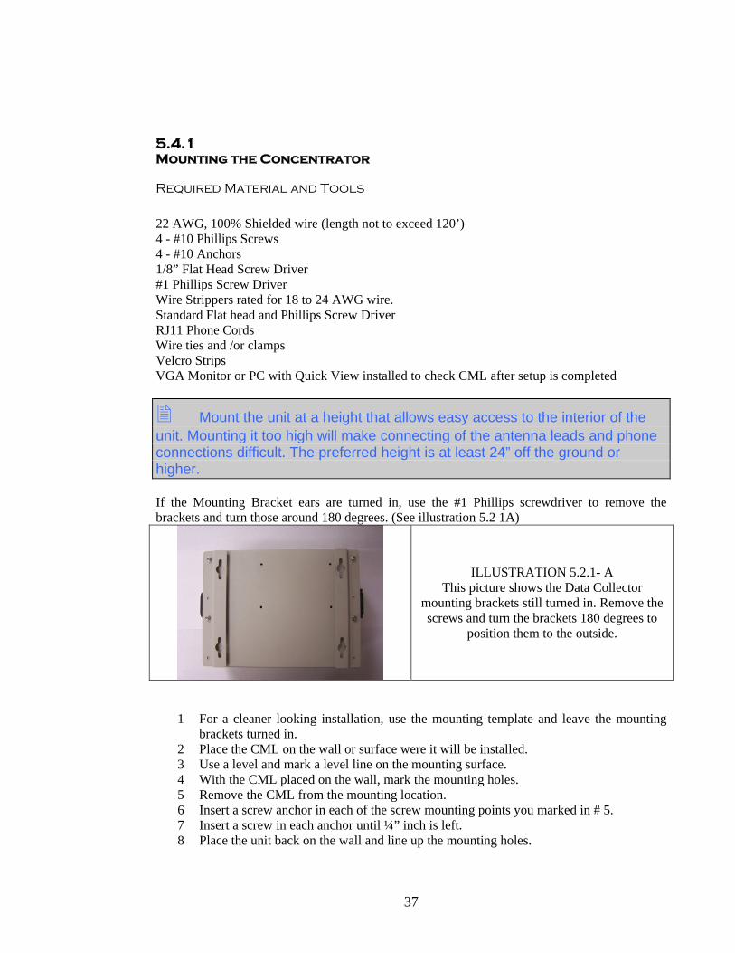
Mount the unit at a height that allows easy access to the interior of the unit. Mounting it too high will make connecting of the antenna leads and phone connections difficult. The preferred height is at least 24” off the ground or higher. If the Mounting Bracket ears are turned in, use the #1 Phillips screwdriver to remove the brackets and turn those around 180 degrees. (See illustration 5.2 1A)
ILLUSTRATION 5.2.1- A This picture shows the Data Collector
mounting brackets still turned in. Remove the screws and turn the brackets 180 degrees to
position them to the outside.
1 For a cleaner looking installation, use the mounting template and leave the mounting brackets turned in.
2 Place the CML on the wall or surface were it will be installed. 3 Use a level and mark a level line on the mounting surface. 4 With the CML placed on the wall, mark the mounting holes. 5 Remove the CML from the mounting location. 6 Insert a screw anchor in each of the screw mounting points you marked in # 5. 7 Insert a screw in each anchor until ¼” inch is left. 8 Place the unit back on the wall and line up the mounting holes.

38
9 Tighten the screws so the unit cannot be easily lifted and removed from the wall. 10 If using the template, place the template in the mounting location. 11 Place the anchors at the four points indicated. 12 Place a screw into each location, making sure not to tighten them down all the way. 13 Position the unit over the screws and slide it down to lock in position.
5.4.2 Connecting the Receiver, Power and Phone
Required wire for the connection of the Main Receiver to the CML is: AWG 22, 3 Conductor, 100% Shielded
It may be easier in some installations to make the following connections before hanging the unit as described in Section 5.4.1
WARNING: Failure to connect the phone line to a UL rated phone surge protection will void all warranties.
WARNING: TURN OFF ALL POWER TO THE CONCENTRATOR UNIT BEFORE MAKING RECEIVER CONNECTIONS.
WARNING: FAILURE TO USE THE PROPERLY RATED 22 AWG, 100% SHIELED WIRE FOR THE RECEIVER TO CONCENTRATOR CONNECTION WILL VOID ALL WARRANTIES.
RECEIVER to CML CONNECTIONS:
Reference Illustration 5.4.2- 1 through 5.4.2 - 4– for details
It is recommended that the installer use a (4) four conductor wire to make the connection from the CML to the receiver unit. The wire colors should be RED, BLACK, GREEN and WHITE so that the connections inside the receiver box match.
1. Strip 1” off the outer jacket off the wire. 2. Remove all shielding back 1” from the outer jacket to expose the 4 conductors. 3. Using a wire stripper strip each conductor back ¼” to expose the wire strand. 4. Using the 1/8” flat screw driver, insert the wires as follows: 5. Red to + 6. Black to – 7. White to TXD 8. Green to RXD

39
9. Tighten the connection terminals to a tight snug fit. 10. Gently pull on each wire to insure that the wire is securely in place
Illustration 5.4.2 -1 Side View of the Data Collector showing the
CML to RECEIVER Terminal Block
Illustration 5.4.2 – 2 The RED or POSITIVE wire has been stripped
and is being inserted in the CML to RECEIVER terminal block
ILLUSTRATION 5.4.2 -3 After stripping and inserting all 4 wires in the terminal block, tighten the terminal screws.
ILLUSTRATION 5.4.2 – 4 This picture shows all 4 wires inserted and
connected to the terminal block

40
5.5 SYSTEM INSTALLATION
Antenna and Receiver Installation
The SpeedRead Concentrator is shipped with a Concentrator Receiver Unit and an Antenna. The Receiver Unit is designed for interior installation and exterior installation. Exterior installation guidelines may differ slightly than those for an exterior installation. (For specifications for external installations please contact SpeedRead Technologies) The Receiver Unit does not require a power supply as it receives its power via the concentrator connection. Installation of the Receiver Unit and Antenna can be as close to the Concentrator as needed or it may be mounted up to 300’away from the Concentrator. The Receiver’s Antenna is designed for external or internal installation. Connection of the Receiver Unit to the Antenna is made via (2) coaxial cables. A high grade coaxial cable with low db loses is recommended for the connections. The Antenna to Receiver Unit connection is made via a coaxial cable. The type of cable used is dependent upon the distance one wishes to mount the antenna from the Receiver Unit. Maximum length of the Coaxial Cable is 200’ using a coaxial cable with the following specs: Max Frequency, GHZ 20.0 Velocity Percent 82 Peak Power Rating, kW 6.4 Dc resistance, ohms / 1000 ft (1000 m) Inner 1.9 (6.2) Outer 2.0 (6.5) dc Breakdown, volts 1600 Jacket spark, volt RMS 4000 Capacitance, pT /ft (pF/m) 24.6 (80.6) Inductance, μ H/ft (μH/m) 0.063 (.0205) Attenuation and Average Power Rating @450 MHz Atten db/100ft (db/110m) 3.89 (12.8) Coaxial less 20 feet or less can use a standard RG-58 Coaxial.

41
5.4.3 Mounting the Antenna and the Receiver Unit
REQUIRED MATERIALS AND TOOLS
Since the installation of the unit’s receiver and antennas vary from location to location only general installation procedures are discussed.
Coaxial Cable RG58 Coaxial up to a maximum of 20 feet length Andrew 1.4” Super flex Cable for lengths up to 200’ Lightening Protective Devices (Required for exterior installations) Antenna pole bracket if unit is to be mounted on a pole Weather proof sealant or tape should be used to seal exposed coaxial connections. 1/8” Flat Head Screw Driver Standard # 1 s Screw Driver Wire strippers Wire ties and/or anchors for coaxial cable. Scotch Lock wire splices or other wire splice devices.
The Receiver unit is designed with an IP 66 rating that allows it to be installed outdoors. To mount the receiver in an outdoor environment the installer must follow the correct procedure detailed below to insure the Receiver’s water protection is not compromised. The Receiver has a field lead of 10’ of 22 AWG Shielded wire preinstalled on the box. Therefore the installer does not need to open the Receiver case to attach the wire leads.
WARNING: If the Receiver is being mounted outside contact SpeedRead technologies for the required material and recommendations for outdoor use.
WARNING: If the Receiver is being mounted outside the installer should verify that the case is secured and that only wire rated for exterior applications is used.
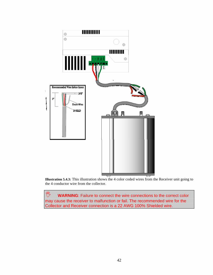
1. Attach the 22 AWG wire that you connected to the Collector Terminals to the 22 AWG Wires coming from the Receiver. Make sure to connect the wires to the correct color: Red from Receiver to Red from Collector, Black from the Receiver to Black from the Collector, White from the Receiver to White from the Collector and Green from the Receiver to Green from the Collector, using SR2 Scotch locks or wire splices designed for 22 AWG wire.
42
Illustration 5.4.3: This illustration shows the 4 color coded wires from the Receiver unit going to the 4 conductor wire from the collector.
WARNING: Failure to connect the wire connections to the correct color may cause the receiver to malfunction or fail. The recommended wire for the Collector and Receiver connection is a 22 AWG 100% Shielded wire.
43
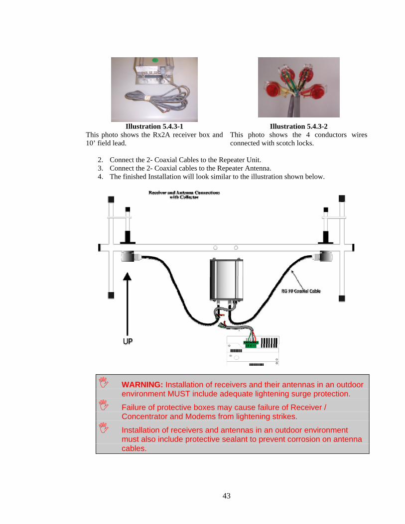
Illustration 5.4.3-1 Illustration 5.4.3-2
This photo shows the Rx2A receiver box and 10’ field lead.
This photo shows the 4 conductors wires connected with scotch locks.
2. Connect the 2- Coaxial Cables to the Repeater Unit. 3. Connect the 2- Coaxial cables to the Repeater Antenna. 4. The finished Installation will look similar to the illustration shown below.
WARNING: Installation of receivers and their antennas in an outdoor environment MUST include adequate lightening surge protection.
Failure of protective boxes may cause failure of Receiver / Concentrator and Modems from lightening strikes.
Installation of receivers and antennas in an outdoor environment must also include protective sealant to prevent corrosion on antenna cables.
44
1. You may now mount the antenna to any flat surface or pole by using the antenna bracket shipped with the antenna. The Antenna is pre-drilled with two mounting holes located in the center of the horizontal bar. If the Antenna will be mounted on a pole use an approved antenna bracket to mount it.
2. The antenna should be mounted in a horizontal position directly above the Receiver Unit. Examination of the antenna will show that the antenna has two smaller antenna posts on the left and right side of the antenna. These posts must be mounted in a vertical position. See Illustration 5.4.3-3 below
3. If the antenna is located outside, then a non-corrosive compound should be applied to the antenna coaxial connections to reduce corrosion.
4. Secure the Receiver Box securely to the mounting surface as shown in the following illustration.
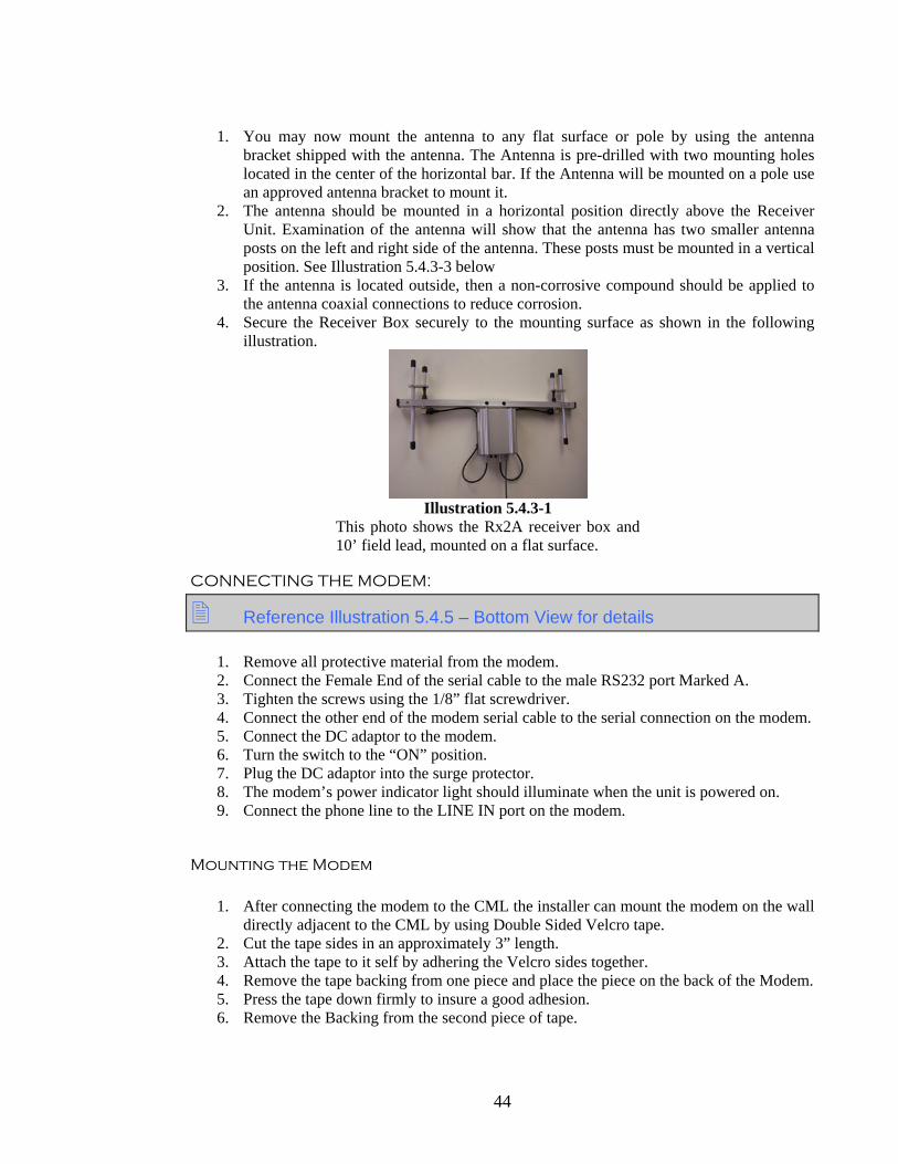
Illustration 5.4.3-1
This photo shows the Rx2A receiver box and 10’ field lead, mounted on a flat surface.
CONNECTING THE MODEM:
Reference Illustration 5.4.5 – Bottom View for details
1. Remove all protective material from the modem. 2. Connect the Female End of the serial cable to the male RS232 port Marked A. 3. Tighten the screws using the 1/8” flat screwdriver. 4. Connect the other end of the modem serial cable to the serial connection on the modem. 5. Connect the DC adaptor to the modem. 6. Turn the switch to the “ON” position. 7. Plug the DC adaptor into the surge protector. 8. The modem’s power indicator light should illuminate when the unit is powered on. 9. Connect the phone line to the LINE IN port on the modem.
Mounting the Modem
1. After connecting the modem to the CML the installer can mount the modem on the wall
directly adjacent to the CML by using Double Sided Velcro tape. 2. Cut the tape sides in an approximately 3” length. 3. Attach the tape to it self by adhering the Velcro sides together. 4. Remove the tape backing from one piece and place the piece on the back of the Modem. 5. Press the tape down firmly to insure a good adhesion. 6. Remove the Backing from the second piece of tape.

45
7. Holding the Modem in your hand press the modem onto the wall surface directly adjacent to the modem serial port.
8. After placing the modem on the wall, gently pull the modem off the wall separating the two pieces of Velcro Tape.
9. Secure all wires and power cords using nylon ties, cable staples or other devices, to prevent accidental disconnections.
10. Proceed to Chapter 6: System Installation - Receiver Unit Installation. If the Modem and CML are in a secure area the installer may at his decision set the modem on the shelf or a mounting surface. The installer should insure that the modem is secure and will not pull off or be dislodged from the mounting area.
Reference Illustration 5.4.6 for an illustration on mounting points of the modem.
Mounting the modem as outlined should allow easy removal of the modem as necessary for troubleshooting.
Place the modem in a manner and position that will make viewing the modems indicator lights easy.

46
+ - TXD
RXD
DTR
Bottom View
A.B. C. D. E.
F. G.
A. Modem InterfaceB. Network Rj-45(Not Active)C.PS/2 Keyboard OutletD.Video OutputE.Reset SwitchF. Power indicatorsG. Rs232 Port
LEFT SIDE VIEW
B.
A. Power Cord SocketB. On/ Off Switch
RIGHT SIDE VIEW
A.
A. Receiver Connection Block
SPEEDREAD MINI 2000
CONCENTRATOR
Illustration 5.4.5: Detail of CML connections.

47
Illustration 5.4-6: Mini CML installed with Modem
5.4.3 Checking the unit for proper operation
To verify the unit is working properly the installer will need to hook a monitor or have the unit connected to an active phone line for a test download.
1. Plug the Power cable into the power port Marked A on the left side view. 2. Plug the unit into a 110-volt power supply fed through a UL listed Surge Protector.
WARNING: Failure to use a UL listed Surge Protector will void all warranties.
3. Attach the Monitor to the 15-pin video out connector labeled”D”. 4. Attach the Keyboard to the keyboard connector labeled”C”. 5. Locate the On/Off switch located on the left side. 6. Turn on the unit’s power switch.

48
7. The unit will start up and go through the boot mode. 8. Watch the screen during the boot process and watch for any error messages. If you see
any messages, please make note of them in case you need to contact SpeedRead. 9. The Boot Process will do several things:
a. Initiate a check of the system as a normal PC b. During the boot process you should hear a POST beep from the CML. c. Detect the modem.
If the modem is not working properly, or the serial cable is not hooked up correctly the CML unit will make several attempts to detect the modem before it loads the system software.
10. If the CML fails to detect the modem it will still boot and give you a MODEM NOT
INSTALLED message in the general data area. 11. Once the modem is powered on and is detected by the Collector, there should be two
red lights illuminated on the modem panel – “AA” and “CD”. If these both of these lights are not illuminated, then check the steps above and verify the modem is turned on and connected to the collector properly’
If the CML to Receiver interface is connected properly and all the connections are good the CML Screen will show a LISTENING WINDOW in the lower center part of the screen. If after making all connections this window is not visible then the receiver may not be connected properly.
12. If you have not yet hooked up the receiver unit you will get a RECIVER NOT WORKING message. Proceed to Chapter 6 to hook up the Receiver Unit and Antenna.
13. To check the reception of the Concentrator Antenna, use a standard STx unit and initialize a transmission by use of the magnet or the tamper switch.
14. If the Receiver is working properly you will receive a transmit notification on the lower left of the screen.
15. If you are leaving the unit unattended it is advisable to disconnect the Monitor and Keyboard.
5.4.4 Troubleshooting CML Installations
Q: After installing the antenna wire and powering up the unit I get a “Receiver isn’t working” message.
A: Check the leads going to the Receiver and verify that they are connected to the proper terminal connectors on the board. Red to +, Black to – , Green to RXD and White to TXD.
Q: After installing the Antenna and Receiver I get receptions from transmitters, however I still get the “Receiver Is Not Working” message. When I transmit the message goes away then reappears.
A: Check to make sure your connections are tight. Loose connections may cause the CML to loose contact with the RX unit periodically. If the CML looses connection to the RX unit for more than 10 seconds it will initiate the error message. Other causes may be related to the receiver picking up signals from voice frequencies.

49
Q: I have checked all the connections and I still get no reception from the receiver.
A: Try using another Receiver / Antenna Unit. You might also try connecting the Receiver to a short lead at the Concentrator for testing. If the receiver works with the short wire then check the wire from the concentrator to the receiver for cuts, breaks and loose connections. Check to make sure the Receiver Frequency is the same as the transmitter you are testing.
Q: After hooking up the receiver I do not see the “Receiver Not Working” message, but I still do not get a reception of the transmitter test.
A: Make sure the STx unit has been initialized from its sleep mode. See the STx Wake Up Procedures. Initialize the STx unit again. Check to make sure the Receiver Frequency is the same frequency as the transmitter you are testing. Check the label on the back of the transmitter to determine the correct frequency.
Q: When I turn on the CML it does not power up at all. The fan does not run and there is no indicator light on the CML.
A: Check that you have power to the CML and that the plug is securely pushed into the CML.
Q: When I start the CML it goes through the boot process and right after it detects the modem it stops, and a strange set of figures appears just above the lower right corner.
A: The sava.dat file may be corrupt. Delete the sava.dat file and restart the system. OR- Turn the unit off and on several times, each time waiting for it to try and boot. The system will eventually boot to a default sava.dat if the older file is corrupt.
Q: When I start the system I get a Non System Boot Error, what is wrong?
A: It could be that you have a failure of the Flash Disk. Contact SpeedRead.
Q: Does the CML have to be mounted on a wall to work or can it be set flat.
A: The CML has no moving parts other than the CPU fan that would prevent it from being mounted in any particular orientation. Keep in mind that you may need to connect a video and keyboard to it, so mount it in a fashion that would allow you to make these connections with ease.
50
5.6.1 Repeater and Antenna Installation
REQUIRED MATERIALS AND TOOLS
Since the installation of the repeaters and antennas will vary from location to location, only general installation procedures are discussed.
Coaxial Cable
RG58 Coaxial up to a maximum of 20 feet length Andrew 1/4” Superflex Cable for lengths up to 200’, see page 43
Lightening Protective Devices Antenna pole bracket Weather proof sealant or tape for coaxial connections. 1/8” Flat Head Screw Driver Standard # 2 Phillips Screw driver Wire strippers Wire ties and/or anchors for coaxial cable.
INSTALLING THE REPEATER The SPEEDREAD Repeater requires a 12 Volt DC adaptor for power. Recommended ratings are: 110 Volt AC to 12 Volt DC @ 500 MA
1. Repeaters are shipped with a 10’ field lead of 2 conductor 22 AWG wire for the connection to the 12 VDC Adaptor, this eliminates the need to open the case to attach 12 VDC Adaptor to the repeater.
2. Strip the Repeater Field Leads back ½”. 3. Strip the 12 VDC Adaptor leads back ½”
Determine which lead of the 12 VDC adaptor is the POSITIVE and which is the NEGATIVE side of the power. This can usually be determined with a voltage tester capable of reading DC current. Some adaptors have the Negative side marked with writing or a strip of color. Check the documentation with the adaptor.
4. Attach the Positive Lead from the 12 VDC Adaptor to the Positive Lead of the Repeater using approved wire connectors.
5. Connect the Negative lead from the12 VDC Adaptor to the Negative Lead of the Repeater. See the illustrations below for examples.
51
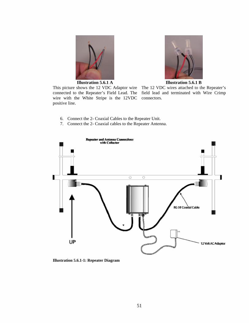
Illustration 5.6.1 A Illustration 5.6.1 B
This picture shows the 12 VDC Adaptor wire connected to the Repeater’s Field Lead. The wire with the White Stripe is the 12VDC positive line.
The 12 VDC wires attached to the Repeater’s field lead and terminated with Wire Crimp connectors.
6. Connect the 2- Coaxial Cables to the Repeater Unit. 7. Connect the 2- Coaxial cables to the Repeater Antenna.
Illustration 5.6.1-1: Repeater Diagram
52
5.6.2 Checking the Repeater for proper operation:
It is important that before the Repeater is installed in its final location the installer verify that the Concentrator is receiving the Repeater. This procedure can be completed while at the Concentrator or while someone watches the concentrator screen. 1. Leave the cover off the repeater box while performing the test. 2. Plug the AC Adaptor to a power supply. 3. When the repeater powers up, determined by the flashing power indicator, initiate a
transmission from a test transmitter. 4. Upon reception by the Repeater the power light will go out and then return back to a
blinking rate. 5. The reception stamp received at the Concentrator with the Repeater Number can verify
repeater reception. 6. If the reception is not received at the Concentrator then go to Trouble Shooting
Repeater Reception, at the end of this section. 7. Do several test transmits to verify that the Repeater is working properly. 8. The unit may now be screwed directly to a mounting surface. 9. The unit may now be installed to any flat surface by two to four screws. 10. Replace the Repeater Unit cover and tighten with a flat head screw driver. 11. Complete the installation by checking the antenna connections on the Repeater and the
Antenna 12. USING A FREQUENCY SCANNER 13. The Repeater can also be checked using a Frequency Scanner and a transmitter
programmed to the same frequency as the Repeater. 14. Set the Scanner to the frequency and transmit the STx unit. 15. You should here the transmitter signal and a fraction of a second later the Repeater will
send out the signal again, which you should get across the scanner as well.

53
5.7 Mounting Considerations and Options
Antenna Mounting options and specifics are to numerous to mention in this document. The actual mounting locations will change from mounting point to mounting point and property to property in some circumstances. Therefore for only general installation guidelines are covered in this manual.
Antenna Mounting Point
The mounting of the antenna to the structure should be done with an approved mounting bracket. SpeedRead supplies mounting brackets free of charge. These brackets are designed for mounting of the antenna to a pole or rail no more than 2“ in diameter. If a larger mounting pole or device is used you should consult the antenna installer for additional brackets. See the illustrations below for an example of the antenna bracket.
Illustration 5.7 A Illustration 5.7 B
This photo shows the antenna bracket attached to the antenna mounting bar. The bolts are
positioned through the antenna’s bar mounting holes.
This photo shows the antenna mounted on a pole with the bracket.
Note that the brackets “teeth” are positioned against the pole to help secure it.
Antennas should not be mounted in such a manner that they could be affected by ghosting, or signals bouncing off the object they are mounting to. An example would be mounting them in front of aluminum or steel siding, near a steel roof, or other material that may affect the antennas performance.
Distances from Antenna to Receiver to Concentrator
When specifying the mounting location the maximum length of Coaxial cable to receiver is 200’ and the coaxial MUST conform to the specifications listed in Section 5.6. Otherwise the MAXIMUM coaxial cable length is 20’ using an RG-58 cable that is detailed earlier in this section.

54
Maximum distances of the 22 AWG, 3 conductor wire used to make the power / data connection to the concentrator is 120’. This wire MUST be 100% shielded. Using these considerations the maximum distance between Antenna and concentrator can be no further than 320’ maximum.
Protection from the Weather
All external antenna connections MUST be protected from weather with proper seals and protective devices. Consult your antenna installers for options available to you. Some options include; sealing tape and dielectric gel to protect coaxial connections. All Receivers should have added protection when mounting them outside. This protection should include an additional protective box that offers sufficient protection from extreme elements. The antenna does not have to be heated nor does it require IP66 specifications, other than those listed above.
Protection from Lightening
When Receivers and Repeater units are mounted outdoors the installer must take precautions to protect the antennas and the units from lightening. Lightening protection specs may vary from place to place and it is beyond the scope of this manual to recommend a lightening surge device that will work in every application. Before installing the device outdoors, the installer should contact SpeedRead Technologies to get further information on types of lightening protection that can be used 5.7.1 Trouble Shooting Repeater Installations
Q: I get no indication that the Repeater is working, using the Collector or using a Scanner, what could be the problem?
A: Make sure the 12 VDC adaptor you are using is wired and working correctly. You can use a Voltage Tester to check the leads for proper voltage, 12 VDC. You should also make sure the 12 VDC Adaptor is wired to the Repeater correctly, Positive to the Red Wire and Negative to the Black wire from the Repeater’s field lead. If these are correct contact SpeedRead Technical Support for support.
Q: After installing the adaptor I get a reception signal on a test transmit, but I do not receive the signal at the concentrator.
A: Check all antenna leads for proper fit. If any of the leads are loose then tighten them to a snug fit using a pair of pliers. Test the transmission again. Loose or bad antenna leads at the Repeaters are the main cause for loss of receptions and/or transmissions.

55
Verify that the concentrator software (COMMSRV) is the latest version available. Older versions of software may not be 100% compatible with newer equipment.
Q: I have checked all the connections and the antenna leads. Everything seems okay, the repeater indicates it has received the signal, but the concentrator never picks it up.
A: Verify that the repeater is the on right frequency for the Receiver. Verify that the concentrator software (COMMSRV) is the latest version available. Older versions of software may not be 100% compatible with newer equipment.
Q: Can I hard wire a 12 Volt DC converter to the Repeater?
A: Yes, as long as the output current is 12volt DC then a hard-wired transformer will work. Q. I have installed two repeaters in the system and verified that both were working before installing them. However, after I installed the repeaters I get areas that they should be picking up receptions, but the STx units that are not coming in. A. Repeaters like STx units can be affected by Collisions of data. This is the problem caused when more than one transmission is received at the Receiver and or the Repeater units at the same time. If the repeaters are numbered the same then they may be receiving STx transmissions and transmitting them at the same time causing data collision. Check the Repeaters ID number and if they are the same change one to the next available number.
Q. How many Repeaters can I use in the system?
A. You can use an unlimited number of repeaters in the system. The only real limitations are related to the Repeaters numbering system (see Section 3, System Components-Repeaters). Repeaters are numbered 1 to 8. Repeaters that are numbered identically should not be in close proximity to each other. A safe guideline is that no two like repeaters should touch the others field of reception.
56
5.8 Programming the Concentrator
REQUIRED MATERIALS AND TOOLS
Standard VGA monitor Standard PS/2 keyboard There are several ways to program the SpeedRead Concentrator. Programming can be done on site with a standard VGA monitor and keyboard attached to the unit. Data may be input directly and then saved. Other means of programming include programming on a standard PC workstation using the Concentrator software Commsrv.exe with a sava.dat file for data. This programming method allows the programmer to work in comfort. This method actually allows the installer to program the concentrator data before the concentrator is installed in the field. Then using SpeedNet to update the programming by transferring the data to the concentrator’s memory. Following are the steps to do a simple program at the concentrator with a keyboard and monitor attached. The same steps can be used when programming with a PC.
The following procedure should be done with a working concentrator. The Concentrator does not need a Receiver or Modem connected for the programming.
1. Hook a monitor and keyboard to the concentrator. 2. Turn the unit on. 3. After the boot process the unit should load the Main Screen.
STEP 1: Checking the System Parameters
Press CRTL + P to open the System Parameters Screen
4. Verify that the following fields are set to these parameters:
COMM DATA Com 1 = 9(Version 2A Receivers) All others should be set to 3. Com 2 = 7 (Version 2.08 Commsrv Only) All other Commsrv Versions should be set to 4. MODEM DATA
Baud = 115200 Rings = 01 Init String = atm0 IRQ = 3 GSM = 0
57
GENERAL DATA Wait = 10
Soft Watchdog = 0 Backup = 24 (0, 4, 6, 8, 12) Save Hour = 0
5. If any of these fields have a wrong setting use the arrow keys to enter the field you wish
to change. Once in the field type in the correct setting and hit ENTER.
Press ESC to exit the Parameters Screen
STEP 2: Setting the Number of Meters
Press CTRL + L Update Collector Capacity Screen
1. Press the right arrow key until you get to the Size Field. 2. Enter the number of “Meters” that will be read by the concentrator. 3. Press the “Enter” key
WARNING: Setting the number of meters to a lower number will permanently delete all meter reading and transmitter data from the collector. This is not reversible.
Press CTRL+S to Save the Data
4. Press ESC to return to the Main Screen.
STEP 3: Entering transmitter Numbers
The current system design allows the installer to enter transmitter serial numbers two separate ways. The following steps are designed to take the installer through the programming process using both methods.
A property layout sheet will be needed to setup the required AMR numbers to matching address locations- See Appendix B.
Press the Up Arrow key until the # 1 AMR is highlighted.
Standard Keyboard Entry
1. When the #1 AMR location has been selected, the row will be highlighted.
58
Press the F5 key to highlight the Transmitters-“TX ID” field for entry of the STx number.
2. Enter the 5 Digit STx Serial Numbers. 3. Once the 5 Digit number is entered the concentrator moves the highlighted cursor to the
Transmitters-“c” column for input of the number of meters that will be read by this STx unit.
4. Enter the number of meters that will be connected to the Transmitter. (For 10 Meters enter a single 0.)
Press Enter.
The cursor will only move to the “c” column on new setups. When changing an already installed STx number the cursor will not allow changes to the “c” column. See Chapter 12: “Changing a Transmitter Number in the Concentrator” for details.
5. The software will install brackets around the required number of AMR locations that you entered.
Press the down or up arrow keys to move to the next AMR location. 6. Repeat steps 1 through 6 to enter all of the STx numbers and complete the setup
process.
Press the “CTRL+S” key periodically to save the entered data. When you have completed entering the serial numbers of the STx units, you will have the required number of STx transmitters entered and the Transmitters will have brackets that will correspond to all of the AMR numbers totaling the number of meters to be read. If this is not correct go to Section 8.3, TROUBLE SHOOTING CONCENTRATOR PROGRAMMING.
USING BARCODE METHOD TO ENTER THE TRANSMITTER SERIAL NUMBERS
The Installer may also use a standard Barcode Gun or other barcode device to enter the transmitter serial numbers into the Concentrator. 1. Install a barcode reader on the concentrator using the recommended manufactures recommendations. No additional software will need to be installed
Press CTL+B to place the system in Barcode Mode

59
2. Use the meter list provided by SpeedRead or you can use the barcode label attached to the top of the transmitter.
Press the Barcode Gun trigger and the barcode will read the barcode and enter the serial number in the next available ADDR field in the system.
3. If you are using a multi port transmitter you will need to enter the number of meters to connect to at this time. 4. Repeat this process until all transmitters have been entered in the system. 5. Proceed to Step 4: Entering Meter Type to complete the programming process.
STEP 4: Entering the Meter Type
WARNING: Failure to set the Meter to the proper type will cause the concentrator to calculate the wrong consumption, resulting in too large or too small consumption readings. This procedure must be followed for all meters including ENCODED meters.
Press the up or down arrows until you highlight the AMR location where you wanted to set the meter type.
1. Select the AMR Location that you wish to change the meter type for.
Press the “F3” key to highlight the Counters-“t” column for the AMR you have selected.
2. Enter the number that corresponds to the meter type installed. 0 = 100 Gallons per Pulse 1 = 1,000 Gallons per Pulse 2 = 1 Gallon per Pulse 3 = 10 Gallons per Pulse 4 = .05 Gallons per Pulse 5 = 2 Gallons Per pulse 6 = 5 Gallons per Pulse 7 = 50 Gallons per Pulse 8 = 36 Gallons per Pulse
3. The cursor will drop to the next field for the meter type. 4. Repeat this process by pressing F3 again.
Press “F2” to save the data.

60
SETTING THE METER TYPE GLOBALY
Current design allows the installer to set all meter types or a series of meter types addressed by AMR number using a global command. This ability greatly increases the ability to enter of change this setting quickly.
Press CTL + R
1. The bottom message Section of the screen will show the following information
Illustration 5.8 -1
Enter the starting AMR were you wish the Meter Types to start.
Press Enter 2. The cursor will go to the next field
Enter the ENDING AMR number were you wish the meter types to stop
Press Enter
Illustration 5.8.-2 – The From AMR and To AMR have now been entered.
3. The cursor will advance to the Meter Type Field 4. Enter the correct Meter Type as detailed below
Enter the Correct Meter type from the list below
Press Enter
0 = 100 Gallons per Pulse 1 = 1,000 Gallons per Pulse 2 = 1 Gallon per Pulse 3 = 10 Gallons per Pulse 4 = .05 Gallons per Pulse 5 = 2 Gallons Per pulse 6 = 5 Gallons per Pulse 7 = 50 Gallons per Pulse 8 = 36 Gallons per Pulse

61
The system will now change all meter types to the setting you selected.
Illustration 5.8-3: This picture shows that Starting AMR Number, Ending AMR Number and the Meter Type entered. The system has now changed all meter types to 3.
Press “F2” to save the data.

62
STEP 5 Entering Meter Readings – ALL METER TYPES
Press the up or down arrows to highlight the AMR you want to enter the meter readings for.
1. Select the AMR location
Press the “Enter” key to highlight and select the Counters-“reading” column.
2. Enter the meter reading as it appears on the Meter Face. Include all digits.
Press the “Enter” key to enter the reading and leave the field.
3. Repeat this process for all meter readings.
STEP 6: Updating System Date and Time
The transmitter time stamp is entered using the CMLs system time. If the date and time should need to be updated then the following steps should be taken.
Press “CTRL+S” to save all current data.
Press “ALT”+”Q” to shut down the system.
As the concentrator software closes, the system will close the modem and leave the “Main Screen”.
1. After the system shuts down it will go to a c :\> prompt. 2. To set the Date.
Type in “date”.
Press the Enter key

63
The current system date will appear. If it is correct press “Enter” to return to the c :\> prompt.)
3. Type in the date using this format dd/mm/yyyy
Press the Enter key. 4. The system will return to the c:\ prompt 5. To set the Time.
Type in “time”.
Press the Enter key
The current system time will appear. If it is correct press the “Enter” key to return to the c :\> prompt)
Current system time MUST be set in 24 Hour Time, 1:00 PM is set as 13:00, 7:00 PM is set as 19:00
6. Type in the time using this format hh:mm:
Press the “Enter” key. 7. The system will return to the c:\ prompt 8. You can check the date and time by the following procedure:
Type in “time”
Press the “Enter” key. 9. The current time will appear.
Press “Enter” again to return to the c:\ prompt.
10. Repeat steps 5 through 7 to check the time. 11. To Restart the system

64
Type “mt” at the c :\> prompt and press the “Enter” key.
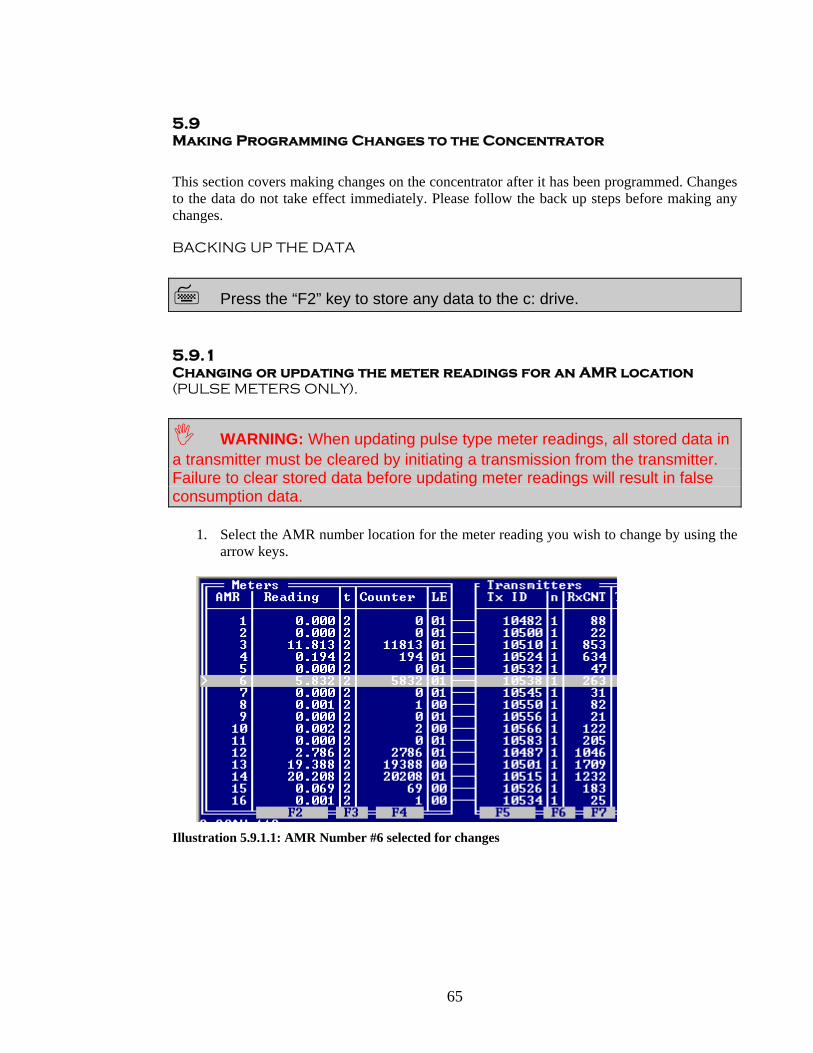
65
5.9 Making Programming Changes to the Concentrator
This section covers making changes on the concentrator after it has been programmed. Changes to the data do not take effect immediately. Please follow the back up steps before making any changes.
BACKING UP THE DATA
Press the “F2” key to store any data to the c: drive.
5.9.1 Changing or updating the meter readings for an AMR location (PULSE METERS ONLY).
WARNING: When updating pulse type meter readings, all stored data in a transmitter must be cleared by initiating a transmission from the transmitter. Failure to clear stored data before updating meter readings will result in false consumption data.
1. Select the AMR number location for the meter reading you wish to change by using the arrow keys.
Illustration 5.9.1.1: AMR Number #6 selected for changes

66
Press the ‘F2’ key to highlight the reading field. (See Illustration 5.9.1.2)
Illustration 5.9.1.2: Reading field selected for changes, notice the brackets around the reading data.
2. Enter the current meter reading.
Illustration 1 5.9.1.3: After changes have been made to AMR # 6.
Press “Enter”
3. The cursor may drop to the next line if there is data on the next line.
Press “F2” to save the data.
67
Encoded Meters with Large Amounts of Data
STx units are designed to hold the last six-meter readings in their internal memory. This ability is used for the transmitter to check each new reading with the last memory locations holding collected data to verify that there is no malfunction present. This design will create a delay when connected to encoded registers with large data already present. Here is an example of what is caused by this STx behavior:
1. You connect a STx to an Encoded meter register head with 123550 gallons on the register.
2. You use a magnet on the STx to wake it. 3. Upon the wake up procedure the STx wakes and checks in to the CML. 4. Upon the first reception the STx sends no data at all. 5. You make another forced transmission and the STx sends some data but not all. 6. After four attempts the STx finally updates the reading to the correct reading.
As can be seen, this design may cause the technician to falsely believe the STx is not reading the register head properly unless they are familiar with this protocol.
Pulse Meters with Large Amounts of Collected Pulses
The Encoded Meter issue described above is also related to transmitters with large amounts of collected data. As the transmitters store cumulative data they can after a long period of service, have anywhere from 65,535 pulses or 1,048,576 pulses depending on the transmitter type. This cumulative collection of data causes the system to verify that incoming data is accurate and that the transmitter is not malfunctioning. An example of this issue is described as follows:
1. A transmitter has been installed for 10 years and is removed from the system. At the time it was removed it had collected 23,464 pulses off of a 10 gallon meter, or 234,640 Gallons.
2. It is then reinstalled at another property and initialized by a magnet. 3. On the first magnet swipe the system accepts the transmission but the read is only
incremented by a portion of the pulses. As an example it goes up to 34,640. 4. Each subsequent swipe of the magnet causes the reading to advance further. On the
second swipe it goes up to 134,640. 5. After 5 swipes of the magnet the reading stops at the 234,640 Gallons, with the number
of pulses at 23,640. This issue is created by the same internal function of the transmitter and data collector that tells it that large amounts of data should not occur. The system thus refuses the data until subsequent transmissions are received and the system verifies that transmitter’s data is stable. However, if the field technician sets the meter type to a 1:1 ration the system may take all the data immediately. It is when the READING itself is incremented in large jumps that this issue is most apparent. 5.9.2

68
Changing Transmitter Numbers in the Concentrator
1. A monitor and keyboard must be connected to the concentrator. 2. Wake up the new transmitter if it is in sleep mode. (See Chapter 5) 3. If the transmitter is used then YOU MUST INITIATE A TRANSMIT TO CLEAR
OUT STORED DATA. 4. Initiate a test transmittion from the new transmitter.
Press “ALT +T” and enter the old 5 digit STx number you are changing and the system will jump to the STx you are changing or scroll down to the AMR location were the STX numbers are installed.
Press the F5 key, to select the transmitter location.
Illustration 5.10: Transmitter selected for replacement.
5. Enter the new 5-digit number for the transmitter.
After 5 digits are entered the field drops to the next line.

69
Illustration 5.10-2: Transmitter changed.
The “out1” column will update to “0” automatically when a transmitter serial number is changed, this cannot be stopped.
6. Go to Section 5.9.1 Changing or Updating Meter Readings, if they need to be updated.
5.9.3 Troubleshooting Concentrator Programming
Q: Should I set up the Concentrator before I activate my Transmitters?
A: Although this is not required it will allow the Concentrator to date and time stamp the transmission on the STx unit as it is brought out of sleep mode. It also adds a layer of verification that the transmitters are awake and the STx number is correct.
Q: I set up all my AMR Locations and entered the STx serial numbers then I realized that I left several locations out. What can I do to correct the error?
A: You cannot insert missed or new STx numbers in the center of a programmed Concentrator. If you errantly programmed all STx numbers and left some out, then you must add them to the end of the data fields. See Section 5.8 Programming the Concentrator.

70
Q: When I am entering data sometimes the cursor field will move down one location by itself. I then have to go back up to the AMR location to enter the data. Why does this happen?
A: This is a safety feature of the software program. Once a field is selected for data entry, the Concentrator will not scan for transmissions. If you select a field and forget to enter data or get distracted the concentrator will unselect the field and allow the Concentrator to start scanning for transmissions. If this did not happen then you might select a field in error and it would not scan for transmissions.
Q: What are Zones and what can I do with them?
A: The current system does not support Zones and this should be excluded form any programming.
Q: How can I get a unique number or address assigned to each location?
A: The COMMSRV software that is located in the Concentrator only accepts basic AMR numbers for each meter attached to the system. The Quick View interface allows for the entry of Address fields that may be downloaded to the CML. Unique numbers can be created from within SpeedNet, see SpeedRead for additional info on this procedure.
Q: When I change out a Transmitter and enter the new one the “Out1” Column changes to “0”. Does this effect or alter the readings?
A: This is normal. The software assumes that there is no collected data in the transmitter and it resets the out1 column to “0”. If the Transmitter has been previously used then you MUST follow the instructions in Section 5.9. Changing or updating a Meter Reading
Q: Is there an easier way to get to an AMR location other than scrolling down?
A: Press ALT+A, the system will prompt you for the AMR number you wish to go to. This same procedure will work for STx numbers if you press ALT+T.
Q: Is there an easier way to locate a specific transmitter other than scrolling down to find it?
A: Press ALT+T, the system will prompt you for the STx number you wish to go to.

71
5.10 Transmitters
Types of transmitters
As described earlier in Section 4 System Components-Transmitters, there are several types of transmitters all designed for specific utility meter designs.
Waking up the STx Transmitter for Installation
For this procedure use a video display connected to the CML.
The SpeedRead Transmitters are shipped from the factory in “Sleep Mode”. This shipping procedure allows the transmitters to be stored for long periods without loss of battery life. Before installation the transmitters must be “Initiated” or brought out of sleep mode. A working Concentrator, Hand Held Rx unit (I.e. a scanner) or a Laptop in CML Mode with a receiver attached should be used for initiating STx Transmitters. This will insure that the transmitters are awake and that the Concentrator is receiving their signals.
Current STx Models – All Versions
Current STx transmitter models can be brought out of sleep mode by passing a magnet across the front panel of the case. In most cases only one pass of the magnet will be required. See the following illustration for an example.
Illustration 5.10
Wake up the STx unit by placing the magnet over the SpeedRead label on the front of the STx case, or you may wave it across the cover.
Older STx Models
In the older STx Transmitters, a Jumper designed to jumper the first 4 pins is required. In later versions the first set of pins can be jumped together or in the case of waterproof units the first set of meter leads can be used.
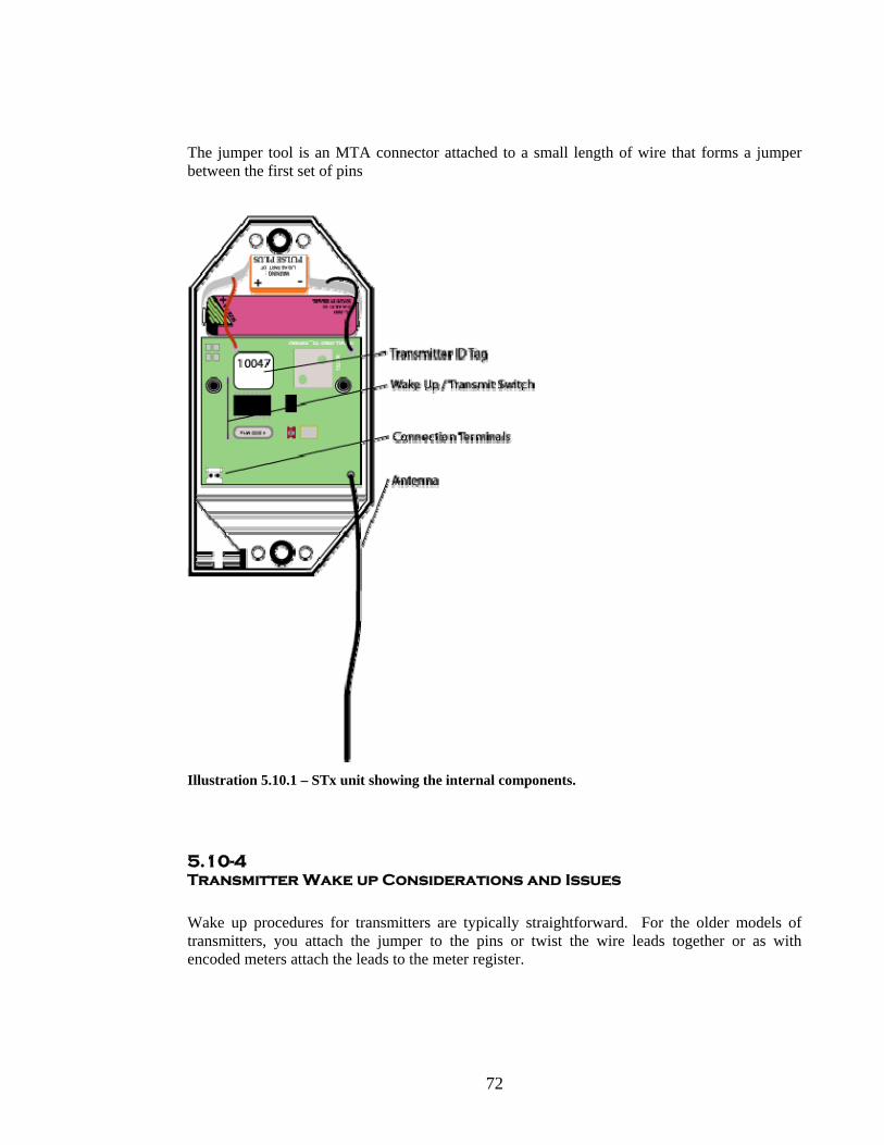
72
The jumper tool is an MTA connector attached to a small length of wire that forms a jumper between the first set of pins
Illustration 5.10.1 – STx unit showing the internal components.
5.10-4 Transmitter Wake up Considerations and Issues
Wake up procedures for transmitters are typically straightforward. For the older models of transmitters, you attach the jumper to the pins or twist the wire leads together or as with encoded meters attach the leads to the meter register.

73
You then wave a magnet over the wake up read switch (see Illustration 5.10-1) and the STx unit is brought out of sleep mode and functions as designed. This procedure is typically immediate and the field technician can see the results almost immediately when a screen is attached to the concentrator. This is not always the case with encoded STx units. The process by which the transmitter retrieves the reading information from the data collector may take several seconds to complete before the transmission is initiated. This creates a delay before the field technician may see or hear the transmission. This phenomenon is even more apparent on STx 3 Encoded transmitters as the STx unit must go to each register in turn to retrieve the register reading.
Encoded Meters with Large Amounts of Data
STx units are designed to hold the last six-meter readings in their internal memory. This ability is used for the transmitter to check each new reading with the last memory locations holding collected data to verify that there is no malfunction present. This design will create a delay when connected to encoded registers with large data already present. Here is an example of what is caused by this STx behavior:
7. You connect a STx to an Encoded meter register head with 123550 gallons on the register.
8. You use a magnet on the STx to wake it. 9. During the wake up procedure, the STx wakes and checks into the CML. 10. Upon the first reception the STx sends no data at all. 11. You make another forced transmission and the STx sends some data but not all. 12. After four attempts the STx finally updates the reading to the correct reading.
As can be seen, this design may cause the technician to falsely believe the STx is not reading the register head properly unless they are familiar with this protocol.
Pulse Meters with Large Amounts of Collected Pulses
The Encoded Meter issue described above is also related to transmitters with large amounts of collected data. As the transmitters store cumulative data they can after a long period of service have anywhere from 65,535 pulses or 1,048,576 pulses depending on the transmitter type. This cumulative collection of data causes the system to verify that incoming data is accurate and that the transmitter is not malfunctioning. An example of this issue is described as follows:
6. A transmitter has been installed for 10 years and is removed from the system. At the time it was removed it had collected 23,464 pulses off of a 10 gallon meter, or 234,640 Gallons.
7. It is then reinstalled at another property and initialized by a magnet. 8. On the first magnet swipe the system accepts the transmission but the read is only
incremented by a portion of the pulses. As an example it goes up to 34,640. 9. Each subsequent swipe of the magnet causes the reading to advance further. On the
second swipe it goes up to 134,640.
74
10. After 5 swipes of the magnet the reading stops at the 234,640 Gallons, with the number of pulses at 23,640.
This issue is created by the same internal function of the transmitter and data collector that tells it that large amounts of data should not occur. The system thus refuses the data until subsequent transmissions are received and the system verifies that transmitter’s data is stable. However, if the field technician sets the meter type to a 1:1 ratio the system may take all the data immediately. It is when the READING itself is incremented in large jumps that this issue is most apparent.
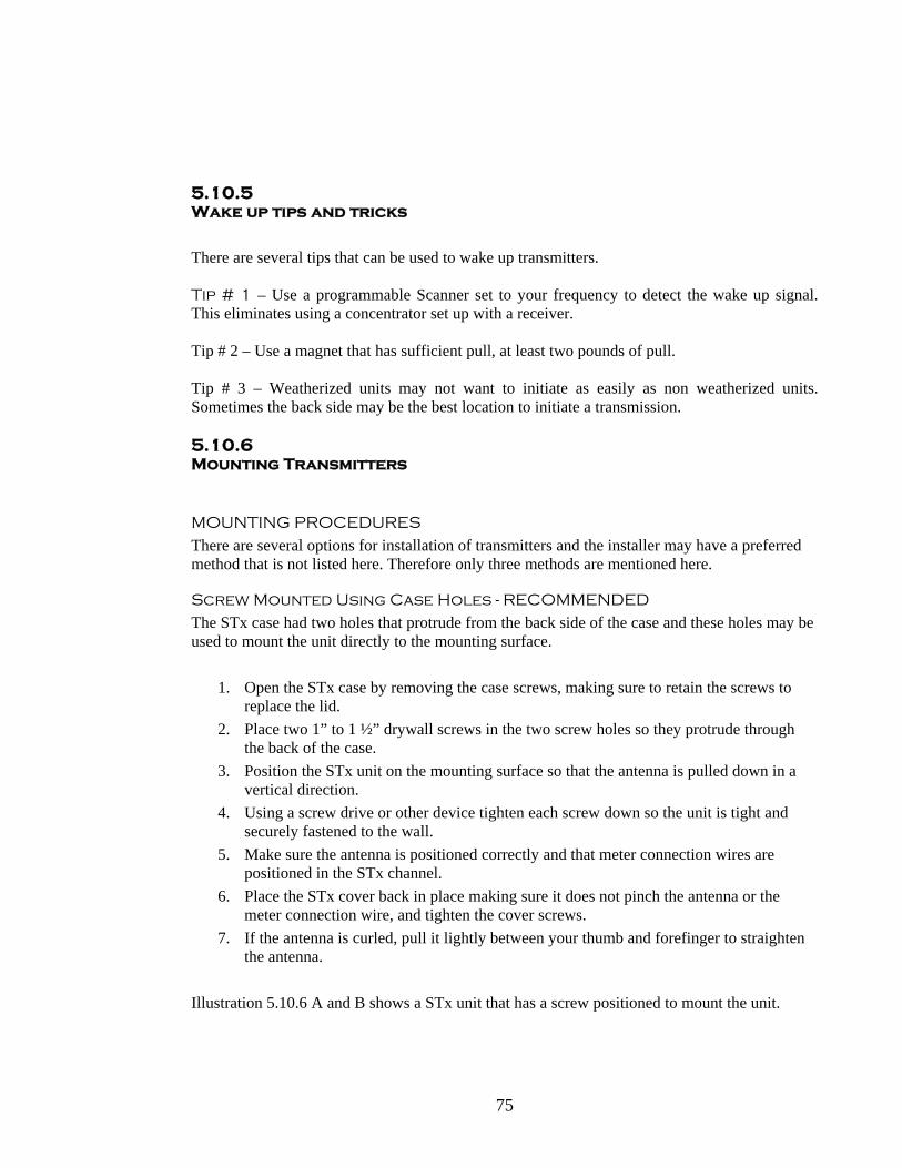
75
5.10.5 Wake up tips and tricks
There are several tips that can be used to wake up transmitters. Tip # 1 – Use a programmable Scanner set to your frequency to detect the wake up signal. This eliminates using a concentrator set up with a receiver. Tip # 2 – Use a magnet that has sufficient pull, at least two pounds of pull. Tip # 3 – Weatherized units may not want to initiate as easily as non weatherized units. Sometimes the back side may be the best location to initiate a transmission.
5.10.6 Mounting Transmitters
MOUNTING PROCEDURES
There are several options for installation of transmitters and the installer may have a preferred method that is not listed here. Therefore only three methods are mentioned here.
Screw Mounted Using Case Holes - RECOMMENDED
The STx case had two holes that protrude from the back side of the case and these holes may be used to mount the unit directly to the mounting surface.
1. Open the STx case by removing the case screws, making sure to retain the screws to replace the lid.
2. Place two 1” to 1 ½” drywall screws in the two screw holes so they protrude through the back of the case.
3. Position the STx unit on the mounting surface so that the antenna is pulled down in a vertical direction.
4. Using a screw drive or other device tighten each screw down so the unit is tight and securely fastened to the wall.
5. Make sure the antenna is positioned correctly and that meter connection wires are positioned in the STx channel.
6. Place the STx cover back in place making sure it does not pinch the antenna or the meter connection wire, and tighten the cover screws.
7. If the antenna is curled, pull it lightly between your thumb and forefinger to straighten the antenna.
Illustration 5.10.6 A and B shows a STx unit that has a screw positioned to mount the unit.
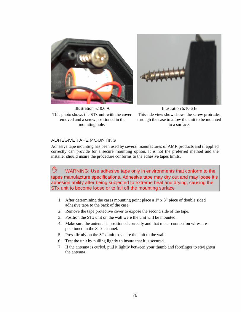
76
Illustration 5.10.6 A Illustration 5.10.6 B This photo shows the STx unit with the cover
removed and a screw positioned in the mounting hole.
This side view show shows the screw protrudes through the case to allow the unit to be mounted
to a surface.
ADHESIVE TAPE MOUNTING
Adhesive tape mounting has been used by several manufactures of AMR products and if applied correctly can provide for a secure mounting option. It is not the preferred method and the installer should insure the procedure conforms to the adhesive tapes limits.
WARNING: Use adhesive tape only in environments that conform to the tapes manufacture specifications. Adhesive tape may dry out and may loose it’s adhesion ability after being subjected to extreme heat and drying, causing the STx unit to become loose or to fall off the mounting surface
1. After determining the cases mounting point place a 1” x 3” piece of double sided
adhesive tape to the back of the case. 2. Remove the tape protective cover to expose the second side of the tape. 3. Position the STx unit on the wall were the unit will be mounted. 4. Make sure the antenna is positioned correctly and that meter connection wires are
positioned in the STx channel. 5. Press firmly on the STx unit to secure the unit to the wall. 6. Test the unit by pulling lightly to insure that it is secured. 7. If the antenna is curled, pull it lightly between your thumb and forefinger to straighten
the antenna.

77
NYLON TIES
Nylon ties can be used in several applications when adhesive tape or screw mounting is not practical. This method is used most often when the meter is not located near the wall or other mounting surface. Nylon ties are most often used to secure the STx unit to the pipe or meter.
1. Use a nylon tie that has enough length to circle the STx unit and the mounting point. 2. Position the STx unit on the mounting surface so that the antenna is not pinched or
impeded by the tie or mounting point. 3. Place the nylon tie around the center of the STx unit so that it passes over the Lid Label. 4. Secure the tie and tighten it using sufficient force to secure the STx unit correctly. 5. Cut the tail of the nylon tie off to insure it can not be tampered with.
Do not over tighten the nylon tie as it may warp the case or cause the case to bend.
6. If the antenna is curled, pull it lightly between your thumb and for finger to straighten
the antenna. 7. Check the STx unit to insure that it is securely fastened.
SpeedRead Clamp
The SpeedRead Clamp is designed to be used with the STx transmitter and certain water meters. It allows the transmitter to be inserted in the clamp and the clamp is then placed over the meter register face.
1. Place the SpeedRead Clamp around the face of eth meter or press it over the body as shown in Illustrations 5.10.7 C and D.
Illustration 5.10.6 C
Shows the Meter Clamp placed around the meter register.
Illustration 5.10.6 D Shows the Meter Clamp being pressed onto a
meter body.

78
2. After the Meter Clamp has been placed on the meter, the transmitter can be connected to the meter register using the AMP connector or Scotch locks as described in Section 10.5.7.
3. Place the Transmitter into the Clamp as shown in Illustrations 5.10.6 E and F.
Illustration 5.10.6 D
The transmitter has been placed in Clamp and is ready to be pressed down into the
locked position.
Illustration 5.10.6 F The transmitter has been placed in Clamp and
is ready to be pressed down into the locked position
4. Press down on the transmitter until it locks into place
with the meter clamp bar.
5. The transmitter is now locked in place and can not be opened unless it is removed from the clamp.
6. The Meter Lead can be placed in the wire groves
located at the back side of the clamp.

79
5.10.7 Meter to Transmitter Connections
Connecting the STx unit to the Meter Register has several options depending on the type of Transmitter and Meter Register that is being interfaced with.
TRANSMITTERS WITH PIN TERMINALS
Transmitters with PIN terminals are designed to have the wire from meter to STx unit terminated with an MTA connector. This termination procedure uses an AMP gun that sets the wire in the MTA connector and then the wire plugs onto the pins located on the STx board.
AMP CRIMPING TOOL: AMP Terminating Head # 58246-1 AMP Handle Assembly # 58074-1
Illustration 10.5.7-1
1. Using a wire stripper, remove 1” off the outer jacket of the meter register wire, Illustration 10.5.7 - 2
2. Remove all shielding and drain wires from the lead, Illustration 10.5.7 - 3 3. Trim the conductors so that any exposed wire is cut even with the conductor insulator.
Illustration 10.5.7 -2 Illustration 10.5.7 - 3
This photo shows the outer jacket removed from the wire and the Shield and Drain pulled
to the side before they are removed.
This photo shows a wire that is properly stripped and prepared before connection to the MTA connector. Note the Shield and Drain have been removed

80
4. Insert the MTA connector into the MTA Gun, Illustration 10.5.7 – 3 5. Using your finger push the MTA connector so that it locks into position, Illustration
10.5.7 – 4. 6. Insert the BLACK or Negative Polarity wire first into the slot on top of the AMP gun,
Illustration 10.5.7 – 5. 7. Press the AMP gun trigger and the wire will be pushed forward and set in to the MTA
connector. 8. Insert the RED or Positive wire into the slot on top of the AMP gun, Illustration 10.5.7
-6. 9. Press the AMP gun trigger and the wire will push forward and set into the MTA
connector, the MTA connector will advance forward to position itself 10. After inserting and setting the second wire the MTA connector will be ejected from the
gun and the wire should be ready to connect to a STx unit, Illustration 10.5.7 – 7. 11. Connect the MTA Connector to the Pins located on the STX unit’s board. Make sure
the wire is placed down and the MTA connector is positioned correctly, Illustration 10.5.7 – 8. Make sure to secure the MTA tightly.
Illustration 10.5.7 – 3 Illustration 10.5.7 – 4 Illustration 10.5.7 – 5
MTA Connector has been placed in the AMP gun
The MTA Connector has been positioned with the first
connector port centered.
The Black Wire has been inserted in the AMP gun and is ready to be set in the MTA
connector
Illustration 10.5.7 – 6 Illustration 10.5.7 – 7 Illustration 10.5.7 - 8
The Black wire has been set and the red wire has been
inserted to be set
After both wires are set correctly the MTA connector will resemble the example in
this photo.
The MTA with the wire attached is ready to be placed
on the STX pins.
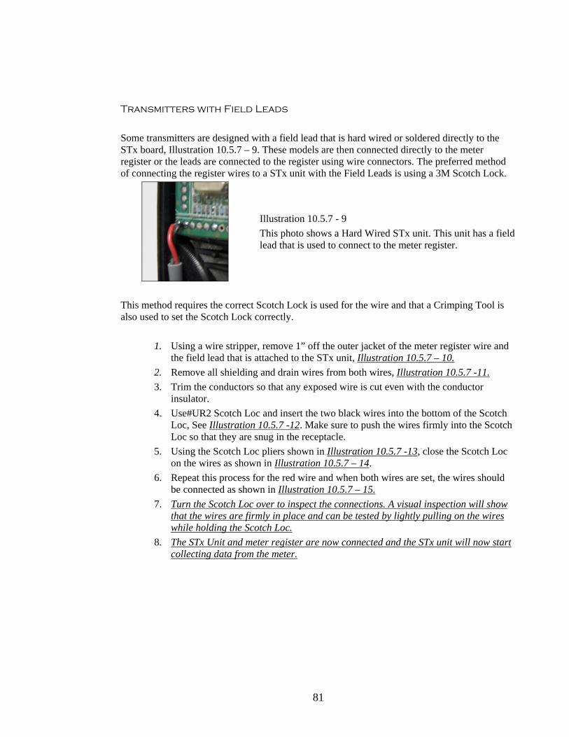
81
Transmitters with Field Leads
Some transmitters are designed with a field lead that is hard wired or soldered directly to the STx board, Illustration 10.5.7 – 9. These models are then connected directly to the meter register or the leads are connected to the register using wire connectors. The preferred method of connecting the register wires to a STx unit with the Field Leads is using a 3M Scotch Lock.
Illustration 10.5.7 - 9 This photo shows a Hard Wired STx unit. This unit has a field lead that is used to connect to the meter register.
This method requires the correct Scotch Lock is used for the wire and that a Crimping Tool is also used to set the Scotch Lock correctly.
1. Using a wire stripper, remove 1” off the outer jacket of the meter register wire and the field lead that is attached to the STx unit, Illustration 10.5.7 – 10.
2. Remove all shielding and drain wires from both wires, Illustration 10.5.7 -11. 3. Trim the conductors so that any exposed wire is cut even with the conductor
insulator. 4. Use#UR2 Scotch Loc and insert the two black wires into the bottom of the Scotch
Loc, See Illustration 10.5.7 -12. Make sure to push the wires firmly into the Scotch Loc so that they are snug in the receptacle.
5. Using the Scotch Loc pliers shown in Illustration 10.5.7 -13, close the Scotch Loc on the wires as shown in Illustration 10.5.7 – 14.
6. Repeat this process for the red wire and when both wires are set, the wires should be connected as shown in Illustration 10.5.7 – 15.
7. Turn the Scotch Loc over to inspect the connections. A visual inspection will show that the wires are firmly in place and can be tested by lightly pulling on the wires while holding the Scotch Loc.
8. The STx Unit and meter register are now connected and the STx unit will now start collecting data from the meter.

82
Illustration 10.5.7 – 10 Illustration 10.5.7 - 11 Illustration 10.5.7 - 12
Illustration 10.5.7 - 13 Illustration 10.5.7 - 14 Illustration 10.5.7 - 15

83
SECTION 6 SYSTEM TROUBLESHOOTING

84
6.1.1 Troubleshooting Collectors Data Collector Will not Download
1. Call the data directly using a standard phone. 2. Does the Collector answer the phone? Yes go to Step # 9 3. No. Cycle the system power using these steps.
a. Power down the Modem b. Power down the Collector. c. Power on the Modem. d. Power on the Collector
4. Does the Collector answer the phone? Yes go to Step # 10 5. No. Check the Following
a. Does the Modem have power lights? b. Is the phone line connected to the modem port for LINE? c. Is the phone line active? d. Is the phone line connected to the wall outlet? e. Is the Collector Powered up? f. Is the phone cord from wall to modem in good condition?
6. Correct any of the items listed above and call the collector using a phone. 7. Does the Collector answer the phone now? Yes got to Step #10 8. No. Replace the modem and try to call again. 9. Try to download the system and watch the download process. 10. Does the Download Complete? Yes, then got to Step # 7 and test the download again.
After the second Download is finished. Quit. 11. Does the download start then stop before it finish? Yes, go to step # 16 12. No, the download never starts or the collector never answers from SpeedNet. 13. Check the Phone number in SpeedNet.. 14. Is the Collector on a Stick or other type of line designator? Yes then got to Step #20 15. Check the Phone line to make sure it is active. Go to step # 5 16. Check the phone line quality to make sure a dirty line is not causing dropped packets
during the download process. Note: Bad or dirty phone lines will cause dropped packets resulting in incomplete downloads or failed connections. 17. Phone line is OK, Replace the Modem and go to Step # 3 18. Phone line may be bad, try connecting to a different phone line to test the connection. 19. Collector downloads on another line fine? Yes, have the phone line checked or repaired. 20. Replace the Modem and go to step # 3. 21. Step 18

85
22. Step 19 23. Bypass the Stick and connect the phone line directly to the Modem, got to step # 9, If
download completes the line designator may be bad. Data Collector will not power up
1. Check the power source using a voltage tester. 2. Power is good, cycle power off then on the collector. 3. Watch the power indicator lights, Yellow on, Green will Blink, Yellow stays on. 4. Power lights do not cycle, check power cord. 5. Power cord is good, system still does not power on. System failure return to SpeedRead
for service. 6. System powers on, system does not post. Power indicator lights cycle but system does
not post. 7. Check Memory SIMMs. If SIMM is loose system will not post. 8. System Post but does not boot. 9. Does software boot? No, Bad Flash Disk return to SpeedRead for service.

86
APPENDIX A: ACTIVE KEYS FOR PROGRAMMING
KEY RESULT
ALT + Q Shuts down Commsrv and returns system to DOS Prompt
F1 (First Time) Menu Screen TAB (First Time) Events Screen TAB (Second Time) Last 20 STx Receptions Screen CTRL + A Prompts for AMR location to go to CTRL + S SAVE the Data CTRL + T Prompts for STx serial # Search CTRL + R Set Meter Pulse Type Globally CTRL+B Turns Barcode Mode on CTRL + P Enter Parameters Screen
CTRL + L Enter Zone and Number of Meters Screen
F2 Enter or change meter reading F3 Update Meter Pulse Type
F4 Update or Change OUT1 (Pulses Collected)
F5 Enter or Change Transmitter Serial No.
F6 Enter or Change Number of Meters Attached
F7 Change Count Column F8 Reset All Faults (Error) Codes
Page Down Move to Next Page or Next 16 AMR Locations
Page UP Move to Previous Page or Previous 16 AMR Locations
Up Arrow Up to Previous AMR Location Down Arrow Down to Next AMR Location
Esc Hitting ESC will return you to the Main Screen

87
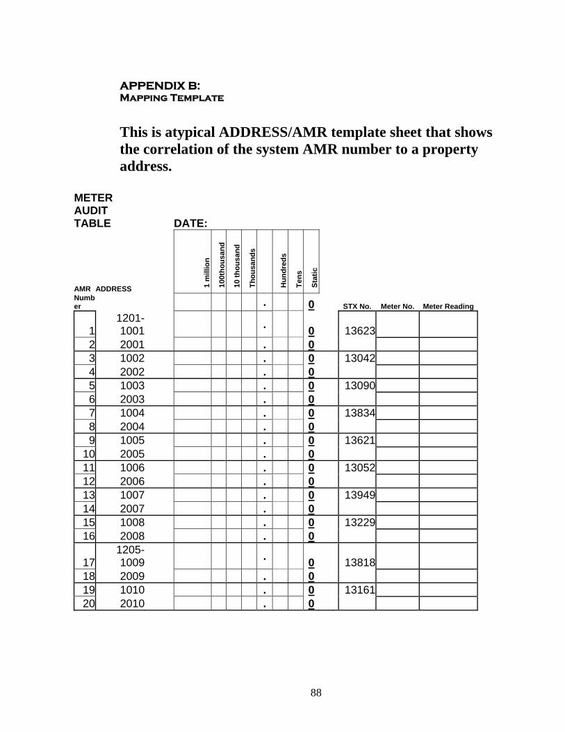
88
APPENDIX B: Mapping Template
This is atypical ADDRESS/AMR template sheet that shows the correlation of the system AMR number to a property address.
METER AUDIT TABLE DATE:
AMR ADDRESS 1 m
illio
n
100t
hous
and
10 th
ousa
nd
Thou
sand
s
Hun
dred
s
Tens
Stat
ic
Number . 0 STX No. Meter No. Meter Reading
11201-1001 . 0 13623
2 2001 . 0 3 1002 . 0 13042 4 2002 . 0 5 1003 . 0 13090 6 2003 . 0 7 1004 . 0 13834 8 2004 . 0 9 1005 . 0 13621
10 2005 . 0 11 1006 . 0 13052 12 2006 . 0 13 1007 . 0 13949 14 2007 . 0 15 1008 . 0 13229 16 2008 . 0
171205-1009 . 0 13818
18 2009 . 0 19 1010 . 0 13161 20 2010 . 0
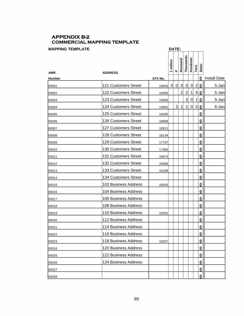
89
APPENDIX B-2 COMMERCIAL MAPPING TEMPLATE
MAPPING TEMPLATE DATE:
AMR ADDRESS 1 m
illio
n d th
ousa
nd
Thou
sand
s H
undr
eds
Tens
St
atic
Number STX No. 0 Install Date
00001 121 Customers Street 10843 0 0 0 0 0 2 0 5-Jan
00002 122 Customers Street 10456 2 2 1 5 0 5-Jan
00003 123 Customers Street 10069 3 0 1 0 5-Jan
00004 124 Customers Street 19682 2 1 1 0 0 0 6-Jan
00005 125 Customers Street 19295 0
00006 126 Customers Street 18908 0
00007 127 Customers Street 18521 0
00008 128 Customers Street 18134 0
00009 129 Customers Street 17747 0
00010 130 Customers Street 17360 0
00011 131 Customers Street 16973 0
00012 132 Customers Street 16586 0
00013 133 Customers Street 16199 0
00014 134 Customers Street 0
00015 102 Business Address 10043 0
00016 104 Business Address 0
00017 106 Business Address 0
00018 108 Business Address 0
00019 110 Business Address 10261 0
00020 112 Business Address 0
00021 114 Business Address 0
00022 116 Business Address 0
00023 118 Business Address 10327 0
00024 120 Business Address 0
00025 122 Business Address 0
00026 124 Business Address 0
00027 0
00028 0
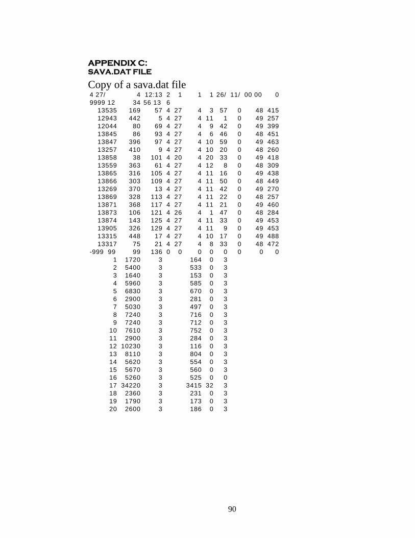
90
APPENDIX C: SAVA.DAT FILE Copy of a sava.dat file 4 27/ 4 12:13 2 1 1 1 26/ 11/ 00 00 09999 12 34 56 13 6
13535 169 57 4 27 4 3 57 0 48 415 12943 442 5 4 27 4 11 1 0 49 257 12044 80 69 4 27 4 9 42 0 49 39913845 86 93 4 27 4 6 46 0 48 451 13847 396 97 4 27 4 10 59 0 49 46313257 410 9 4 27 4 10 20 0 48 260 13858 38 101 4 20 4 20 33 0 49 41813559 363 61 4 27 4 12 8 0 48 309 13865 316 105 4 27 4 11 16 0 49 43813866 303 109 4 27 4 11 50 0 48 44913269 370 13 4 27 4 11 42 0 49 27013869 328 113 4 27 4 11 22 0 48 257 13871 368 117 4 27 4 11 21 0 49 460 13873 106 121 4 26 4 1 47 0 48 284 13874 143 125 4 27 4 11 33 0 49 453 13905 326 129 4 27 4 11 9 0 49 45313315 448 17 4 27 4 10 17 0 49 48813317 75 21 4 27 4 8 33 0 48 472
-999 99 99 136 0 0 0 0 0 0 0 01 1720 3 164 0 32 5400 3 533 0 33 1640 3 153 0 34 5960 3 585 0 35 6830 3 670 0 36 2900 3 281 0 37 5030 3 497 0 38 7240 3 716 0 39 7240 3 712 0 3
10 7610 3 752 0 311 2900 3 284 0 312 10230 3 116 0 313 8110 3 804 0 314 5620 3 554 0 315 5670 3 560 0 316 5260 3 525 0 017 34220 3 3415 32 318 2360 3 231 0 319 1790 3 173 0 320 2600 3 186 0 3
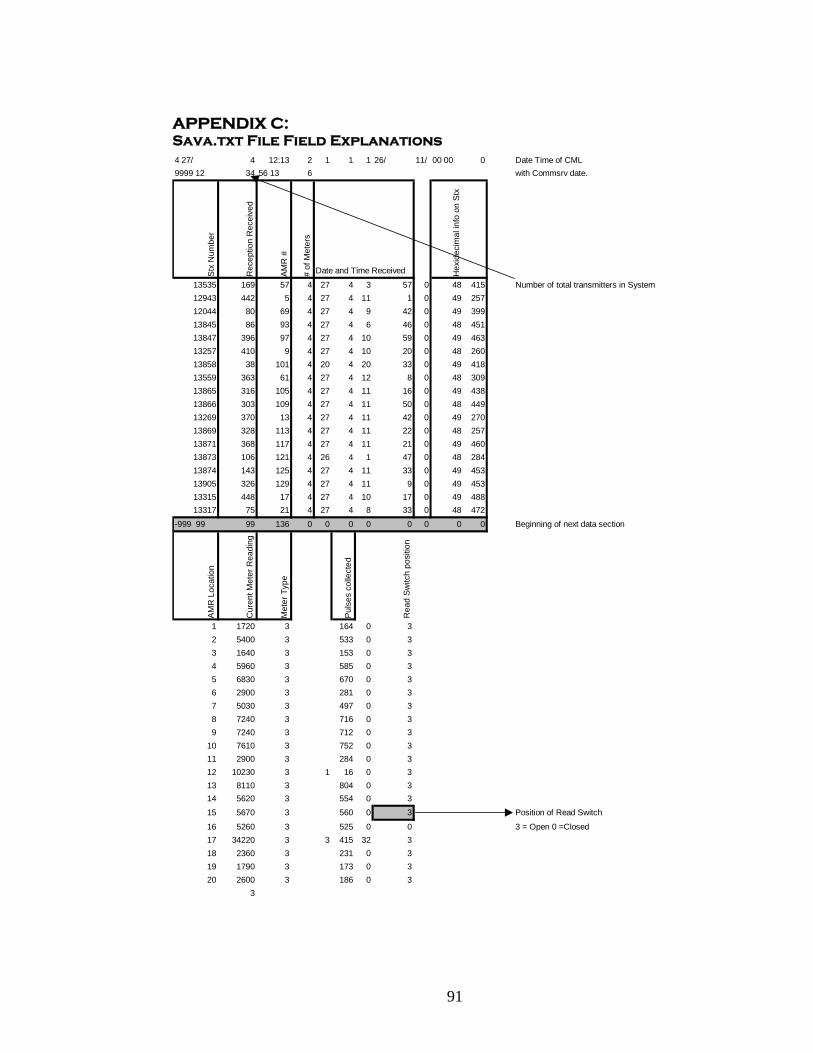
91
APPENDIX C: Sava.txt File Field Explanations 4 27/ 4 12:13 2 1 1 1 26/ 11/ 00 00 0 Date Time of CML 9999 12 34 56 13 6 with Commsrv date.
Stx
Num
ber
Rec
eptio
n R
ecei
ved
AM
R #
# of
Met
ers
Date and Time Received Hex
idec
imal
info
on
Stx
13535 169 57 4 27 4 3 57 0 48 415 Number of total transmitters in System12943 442 5 4 27 4 11 1 0 49 25712044 80 69 4 27 4 9 42 0 49 39913845 86 93 4 27 4 6 46 0 48 45113847 396 97 4 27 4 10 59 0 49 46313257 410 9 4 27 4 10 20 0 48 26013858 38 101 4 20 4 20 33 0 49 41813559 363 61 4 27 4 12 8 0 48 30913865 316 105 4 27 4 11 16 0 49 43813866 303 109 4 27 4 11 50 0 48 44913269 370 13 4 27 4 11 42 0 49 27013869 328 113 4 27 4 11 22 0 48 25713871 368 117 4 27 4 11 21 0 49 46013873 106 121 4 26 4 1 47 0 48 28413874 143 125 4 27 4 11 33 0 49 45313905 326 129 4 27 4 11 9 0 49 45313315 448 17 4 27 4 10 17 0 49 48813317 75 21 4 27 4 8 33 0 48 472
-999 99 99 136 0 0 0 0 0 0 0 0 Beginning of next data section
AMR
Loc
atio
n
Cur
ent M
eter
Rea
ding
Met
er T
ype
Puls
es c
olle
cted
Rea
d Sw
itch
posi
tion
1 1720 3 164 0 3 2 5400 3 533 0 33 1640 3 153 0 3 4 5960 3 585 0 3 5 6830 3 670 0 3 6 2900 3 281 0 37 5030 3 497 0 38 7240 3 716 0 39 7240 3 712 0 3
10 7610 3 752 0 311 2900 3 284 0 312 10230 3 1 16 0 313 8110 3 804 0 314 5620 3 554 0 315 5670 3 560 0 3 Position of Read Switch
16 5260 3 525 0 0 3 = Open 0 =Closed17 34220 3 3 415 32 318 2360 3 231 0 319 1790 3 173 0 320 2600 3 186 0 3
3

92
APPENDIX D: MINI CML LAYOUT
+ - TXD
RXD
DTR
Bottom View
A.B. C. D. E.
F. G.
A. Modem InterfaceB. Network Rj-45(Not Active)C.PS/2 Keyboard OutletD.Video OutputE.Reset SwitchF. Power indicatorsG. Rs232 Port
LEFT SIDE VIEW
B.
A. Power Cord SocketB. On/ Off Switch
RIGHT SIDE VIEW
A.
A. Receiver Connection Block
SPEEDREAD MINI 2000
CONCENTRATOR
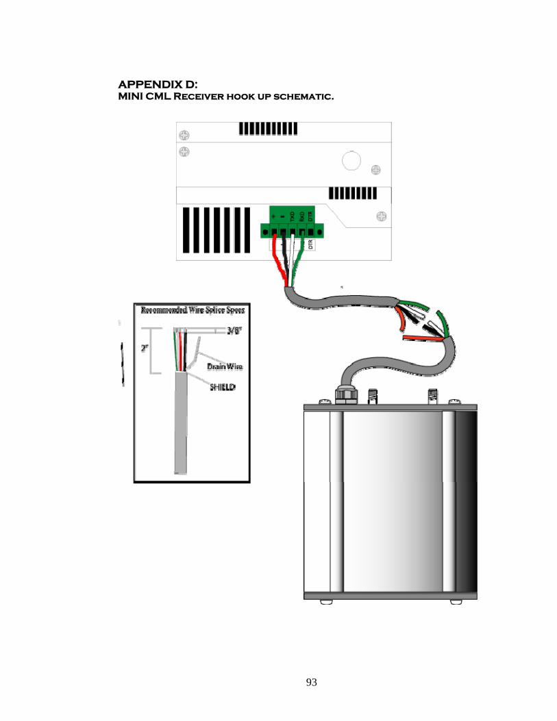
93
APPENDIX D: MINI CML Receiver hook up schematic.

94
APPENDIX E: Mounting Template
Mini Concentrator Mounting Template
4. Remove backing from Template. 5. Place Template on mounting location. 6. Place screws at mounting locations.
Mini Concentrator Mounting Template
1. Remove backing from Template. 2. Place Template on mounting location. 3. Place screws at mounting locations.

95
APPENDIX F: EROR CODES AND DESCRIPTIONS
ERROR CODE # DESCRIPTION CAUSES
#1 The Out Put Status has changed Possible STx malfunction
#2 Number of Pulses (out1) being
sent by the STX is less than what is recorded at the concentrator.
Change of out1 column by user.
Loss of data at the STx level.
#3 RESERVED FOR LATER USE
#4 The Difference between
transmission was more than 20,000 Gallons
Used in Burst pipe detection.
Large consumption. Malfunction of STX
#5 RESERVED FOR LATER USE
#6 VIBRATION OUTPUT or TWO PULSES ATTACHED
Read Switch is vibrating or failing.
Meter pulsing two quick for the STX unit to detect
actual pulses.
#7 LEAK SUSPECION Continuous flow detected at
the meter with out any pause or pulses.
#8 END LEAK SUSPECION
STx detects a period of time that no pulses are detected. This is a response to a # 7
error event

96
APPENDIX G: SAMPLE METER ANALYSIS
Meter and Site Analysis
Property Type Address Meter Register Type Resolution Connections Meter Model LocationResidential 4748 Normal Encoded 100 1 Port Kent Outside
Residential 4646 Kittley Encoded 100 1 Port Kent Outside
Residential 7387 E 53rd Encoded 1000 1 Port Hersey Inside
Residential 5002 Kittley Encoded 1000/100 Compound Neptune Pit/Metal
Residential 6630 E 52nd Passive Pulse 10 1 Port Master Meter Pit/Plastic
Commercial 6640 E 52nd Encoded 1000/100 Compound Schlumberger Pit/ Metal
Light Industrial 6736 52nd Standard Pulse 1 1 Port Hersey Pit / Metal

97
APPENDIX H: SPEEDREAD UTILITY METER VERIFICATION FORM Manufactures Name: ___________________________________ Model: ______________________________________________ Meter Type:
Water Gas Electric
Pulse Output Type:
Encoded Active Pulse (Remote Register) Passive Pulse (Dry Contact Switch)
Attach Picture of Meter Register AND Spec Sheet for Meter Register