Study on Contact State and Contact Stress Distribution of ... on Contact State and Contact Stress...
8
Study on Contact State and Contact Stress Distribution of Kettle Mechanical Seal SHUANGXI LI, HUANLI, KESONG HUANG, QIUXIANG ZHANG, JINING CAI Colleague of Mechanical and Engineering Beijing University of Chemical Technology No.15 of North Three-ring East Road, Chao Yang District, Beijing CHINA [email protected] Abstract— In traditional mechanical seal design, the average transverse stress is used. However, in practice, the distribution of seal face contact tress is not uniform. The contact state and contact stress distribution affect seal face’s state of wear and deformations, which are of vital to the sealability and sealing life. Therefore, in this paper, complete and accurate finite element models of kettle mechanical seal (KMS) rotator ring, stator ring and stator ring seat were established by ANSYS. The seal face contact state and the contact stress distribution were obtained by the finite element analysis. And the influence laws of working pressure P, stator ring height H, load coefficient K, stator ring auxiliary O-ring inner diameter ratio S, etc. on the face performance were analyzed. It was shown that the contact stress distribution may be non-uniform in higher working pressure condition. Besides, the higher the working pressure P was, the more non-uniform the distribution was and the smaller the contact area was. The contact stress distribution was more uniform, the contact area increased and the maximum seal face contact stress decreased with the increasing of H, K and S. The research results were verified by designed test and provide a theoretical basis for the design and optimization of mechanical seal. Keywords:- kettle mechanical seal; contact stress distribution; contact state. 1 Introduction In recent years, with the rapid development of petrochemical, metallurgical and pharmaceutical industries, the application range of kettle has become wider and wider. Kettle mechanical seal (KMS), as the key device of kettle, is required to be advanced especially in the aspect of the operating parameters. So it is imperative to research and develop the high parameter KMS. The contact state of seal face is regarded as ideal parallel plane contact and the contact stress distribution is thought to be uniform in conventional design of mechanical seal. But in fact, the contact stress distribution of seal face is non- uniform and contact state of seal face is not parallel contact, especially when it is under high working pressure. Mechanical seal face contact state and contact stress distribution play a great role in the normal operation of mechanical seal. Convergence or divergence state of seal face may lead to high local contact stress, which can result in partial excessive wear and high temperature, affecting the overall seal face seal performance [1] .Therefore, in practical seal design, if it is carried out based on the seal face average contact stress (that is the seal face specific pressure P c ), which may lead to high seal local contact stress, it will result in sealing failure because of the wear of the seal face. In the view of the research on mechanical seal face contact state and contact stress distribution, xue- ming zhu [2] , liao and marina [3] , Wu Wen [4] , Justin [5] et al. studied the stress field of mechanical seal face. Wei Long, bo-qin gu, jian jun-sun [6-8] et al. used fractal theory to establish the theoretical model of mechanical seal face. Pei-qi ge et al [9] considered the influence of surface roughness and radial taper on seal face. Hui-xia Yang et al [10] considered the effect of micro convex body plastic deformation. Xue-xing ding et al [11] applied micro polar elastic fluid lubrication theory to the study of the mechanical seal. In these studies, the concrete distribution of seal face contact stress, especially its change laws have less been involved. Therefore, the further study of contact state and contact stress distribution of KMS is done by the finite element analysis in this paper. The research result plays an important role in guiding the design and optimization of mechanical seal. 2 The finite element model of KMS The mechanical seal is some high pressure commercial KMS which is dual balance mechanical seal structure, shown in Fig. 1. WSEAS TRANSACTIONS on FLUID MECHANICS Shuangxi Li, Huanli, Kesong Huang, Qiuxiang Zhang, Jining Cai E-ISSN: 2224-347X 49 Volume 11, 2016
Transcript of Study on Contact State and Contact Stress Distribution of ... on Contact State and Contact Stress...
Study on Contact State and Contact Stress Distribution of Kettle Mechanical Seal
SHUANGXI LI, HUANLI, KESONG HUANG, QIUXIANG ZHANG, JINING CAI Colleague of Mechanical and Engineering
Beijing University of Chemical Technology No.15 of North Three-ring East Road, Chao Yang District, Beijing
CHINA [email protected]
Abstract— In traditional mechanical seal design, the average transverse stress is used. However, in practice, the distribution of seal face contact tress is not uniform. The contact state and contact stress distribution affect seal face’s state of wear and deformations, which are of vital to the sealability and sealing life. Therefore, in this paper, complete and accurate finite element models of kettle mechanical seal (KMS) rotator ring, stator ring and stator ring seat were established by ANSYS. The seal face contact state and the contact stress distribution were obtained by the finite element analysis. And the influence laws of working pressure P, stator ring height H, load coefficient K, stator ring auxiliary O-ring inner diameter ratio S, etc. on the face performance were analyzed. It was shown that the contact stress distribution may be non-uniform in higher working pressure condition. Besides, the higher the working pressure P was, the more non-uniform the distribution was and the smaller the contact area was. The contact stress distribution was more uniform, the contact area increased and the maximum seal face contact stress decreased with the increasing of H, K and S. The research results were verified by designed test and provide a theoretical basis for the design and optimization of mechanical seal. Keywords:- kettle mechanical seal; contact stress distribution; contact state. 1 Introduction
In recent years, with the rapid development of petrochemical, metallurgical and pharmaceutical industries, the application range of kettle has become wider and wider. Kettle mechanical seal (KMS), as the key device of kettle, is required to be advanced especially in the aspect of the operating parameters. So it is imperative to research and develop the high parameter KMS. The contact state of seal face is regarded as ideal parallel plane contact and the contact stress distribution is thought to be uniform in conventional design of mechanical seal. But in fact, the contact stress distribution of seal face is non-uniform and contact state of seal face is not parallel contact, especially when it is under high working pressure. Mechanical seal face contact state and contact stress distribution play a great role in the normal operation of mechanical seal. Convergence or divergence state of seal face may lead to high local contact stress, which can result in partial excessive wear and high temperature, affecting the overall seal face seal performance [1].Therefore, in practical seal design, if it is carried out based on the seal face average contact stress (that is the seal face specific pressure Pc), which may lead to high seal local contact stress, it will result in sealing failure because of the wear of the seal face.
In the view of the research on mechanical seal face contact state and contact stress distribution, xue-ming zhu [2], liao and marina [3], Wu Wen [4], Justin [5] et al. studied the stress field of mechanical seal face. Wei Long, bo-qin gu, jian jun-sun [6-8] et al. used fractal theory to establish the theoretical model of mechanical seal face. Pei-qi ge et al [9] considered the influence of surface roughness and radial taper on seal face. Hui-xia Yang et al [10] considered the effect of micro convex body plastic deformation. Xue-xing ding et al [11] applied micro polar elastic fluid lubrication theory to the study of the mechanical seal.
In these studies, the concrete distribution of seal face contact stress, especially its change laws have less been involved. Therefore, the further study of contact state and contact stress distribution of KMS is done by the finite element analysis in this paper. The research result plays an important role in guiding the design and optimization of mechanical seal.
2 The finite element model of KMS The mechanical seal is some high pressure
commercial KMS which is dual balance mechanical seal structure, shown in Fig. 1.
WSEAS TRANSACTIONS on FLUID MECHANICSShuangxi Li, Huanli, Kesong Huang,
Qiuxiang Zhang, Jining Cai
E-ISSN: 2224-347X 49 Volume 11, 2016
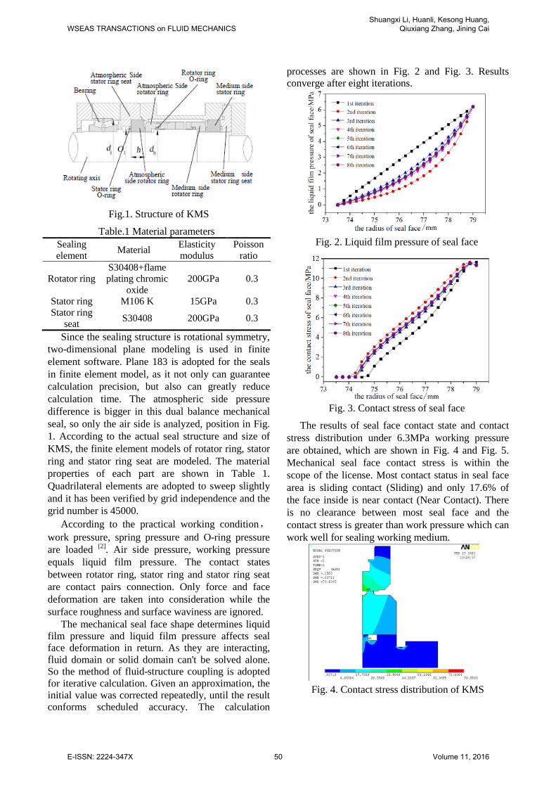
Fig.1. Structure of KMS
Table.1 Material parameters Sealing element Material Elasticity
modulus Poisson
ratio
Rotator ring S30408+flame plating chromic
oxide 200GPa 0.3
Stator ring M106 K 15GPa 0.3 Stator ring
seat S30408 200GPa 0.3
Since the sealing structure is rotational symmetry, two-dimensional plane modeling is used in finite element software. Plane 183 is adopted for the seals in finite element model, as it not only can guarantee calculation precision, but also can greatly reduce calculation time. The atmospheric side pressure difference is bigger in this dual balance mechanical seal, so only the air side is analyzed, position in Fig. 1. According to the actual seal structure and size of KMS, the finite element models of rotator ring, stator ring and stator ring seat are modeled. The material properties of each part are shown in Table 1. Quadrilateral elements are adopted to sweep slightly and it has been verified by grid independence and the grid number is 45000.
According to the practical working condition,work pressure, spring pressure and O-ring pressure are loaded [2]. Air side pressure, working pressure equals liquid film pressure. The contact states between rotator ring, stator ring and stator ring seat are contact pairs connection. Only force and face deformation are taken into consideration while the surface roughness and surface waviness are ignored.
The mechanical seal face shape determines liquid film pressure and liquid film pressure affects seal face deformation in return. As they are interacting, fluid domain or solid domain can't be solved alone. So the method of fluid-structure coupling is adopted for iterative calculation. Given an approximation, the initial value was corrected repeatedly, until the result conforms scheduled accuracy. The calculation
processes are shown in Fig. 2 and Fig. 3. Results converge after eight iterations.
Fig. 2. Liquid film pressure of seal face
Fig. 3. Contact stress of seal face
The results of seal face contact state and contact stress distribution under 6.3MPa working pressure are obtained, which are shown in Fig. 4 and Fig. 5. Mechanical seal face contact stress is within the scope of the license. Most contact status in seal face area is sliding contact (Sliding) and only 17.6% of the face inside is near contact (Near Contact). There is no clearance between most seal face and the contact stress is greater than work pressure which can work well for sealing working medium.
Fig. 4. Contact stress distribution of KMS
WSEAS TRANSACTIONS on FLUID MECHANICSShuangxi Li, Huanli, Kesong Huang,
Qiuxiang Zhang, Jining Cai
E-ISSN: 2224-347X 50 Volume 11, 2016
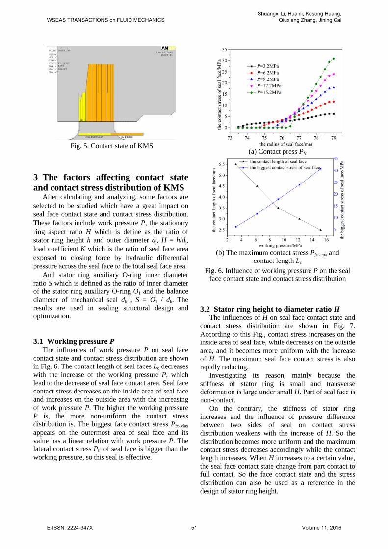
Fig. 5. Contact state of KMS
3 The factors affecting contact state and contact stress distribution of KMS
After calculating and analyzing, some factors are selected to be studied which have a great impact on seal face contact state and contact stress distribution. These factors include work pressure P, the stationary ring aspect ratio H which is define as the ratio of stator ring height h and outer diameter dj, H = h/dj, load coefficient K which is the ratio of seal face area exposed to closing force by hydraulic differential pressure across the seal face to the total seal face area.
And stator ring auxiliary O-ring inner diameter ratio S which is defined as the ratio of inner diameter of the stator ring auxiliary O-ring O1 and the balance diameter of mechanical seal db , S = O1 / db. The results are used in sealing structural design and optimization.
3.1 Working pressure P The influences of work pressure P on seal face
contact state and contact stress distribution are shown in Fig. 6. The contact length of seal faces Lc decreases with the increase of the working pressure P, which lead to the decrease of seal face contact area. Seal face contact stress decreases on the inside area of seal face and increases on the outside area with the increasing of work pressure P. The higher the working pressure P is, the more non-uniform the contact stress distribution is. The biggest face contact stress Pfc-Max appears on the outermost area of seal face and its value has a linear relation with work pressure P. The lateral contact stress Pfc of seal face is bigger than the working pressure, so this seal is effective.
(a) Contact press Pfc
(b) The maximum contact stress Pfc-max and
contact length Lc Fig. 6. Influence of working pressure P on the seal
face contact state and contact stress distribution
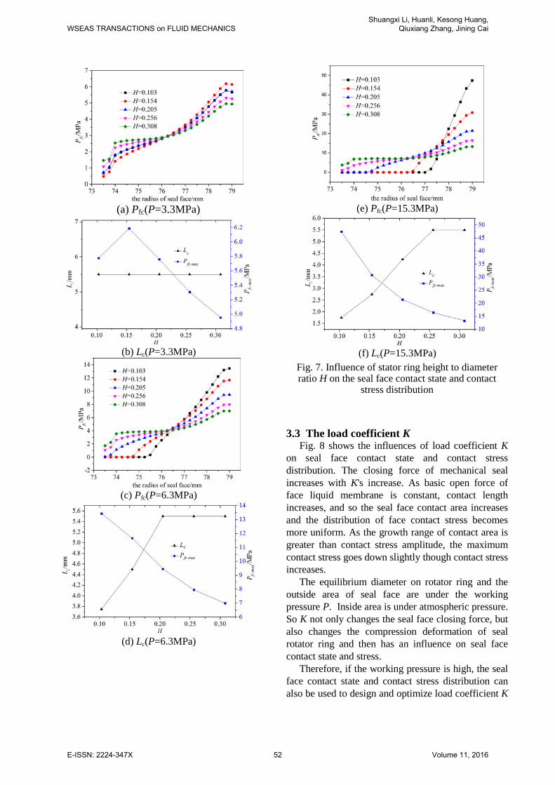
3.2 Stator ring height to diameter ratio H
The influences of H on seal face contact state and contact stress distribution are shown in Fig. 7. According to this Fig., contact stress increases on the inside area of seal face, while decreases on the outside area, and it becomes more uniform with the increase of H. The maximum seal face contact stress is also rapidly reducing.
Investigating its reason, mainly because the stiffness of stator ring is small and transverse deformation is large under small H. Part of seal face is non-contact.
On the contrary, the stiffness of stator ring increases and the influence of pressure difference between two sides of seal on contact stress distribution weakens with the increase of H. So the distribution becomes more uniform and the maximum contact stress decreases accordingly while the contact length increases. When H increases to a certain value, the seal face contact state change from part contact to full contact. So the face contact state and the stress distribution can also be used as a reference in the design of stator ring height.
WSEAS TRANSACTIONS on FLUID MECHANICSShuangxi Li, Huanli, Kesong Huang,
Qiuxiang Zhang, Jining Cai
E-ISSN: 2224-347X 51 Volume 11, 2016
(a) Pfc(P=3.3MPa)
(b) Lc(P=3.3MPa)
(c) Pfc(P=6.3MPa)
(d) Lc(P=6.3MPa)
(e) Pfc(P=15.3MPa)
(f) Lc(P=15.3MPa)
Fig. 7. Influence of stator ring height to diameter ratio H on the seal face contact state and contact
stress distribution
3.3 The load coefficient K
Fig. 8 shows the influences of load coefficient K on seal face contact state and contact stress distribution. The closing force of mechanical seal increases with K's increase. As basic open force of face liquid membrane is constant, contact length increases, and so the seal face contact area increases and the distribution of face contact stress becomes more uniform. As the growth range of contact area is greater than contact stress amplitude, the maximum contact stress goes down slightly though contact stress increases.
The equilibrium diameter on rotator ring and the outside area of seal face are under the working pressure P. Inside area is under atmospheric pressure. So K not only changes the seal face closing force, but also changes the compression deformation of seal rotator ring and then has an influence on seal face contact state and stress.
Therefore, if the working pressure is high, the seal face contact state and contact stress distribution can also be used to design and optimize load coefficient K
WSEAS TRANSACTIONS on FLUID MECHANICSShuangxi Li, Huanli, Kesong Huang,
Qiuxiang Zhang, Jining Cai
E-ISSN: 2224-347X 52 Volume 11, 2016
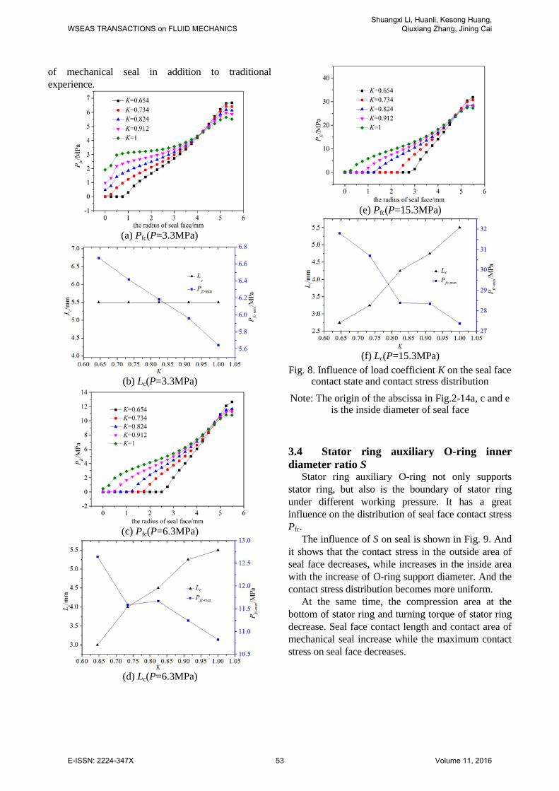
of mechanical seal in addition to traditional experience.
(a) Pfc(P=3.3MPa)
(b) Lc(P=3.3MPa)
(c) Pfc(P=6.3MPa)
(d) Lc(P=6.3MPa)
(e) Pfc(P=15.3MPa)
(f) Lc(P=15.3MPa)
Fig. 8. Influence of load coefficient K on the seal face contact state and contact stress distribution
Note: The origin of the abscissa in Fig.2-14a, c and e is the inside diameter of seal face
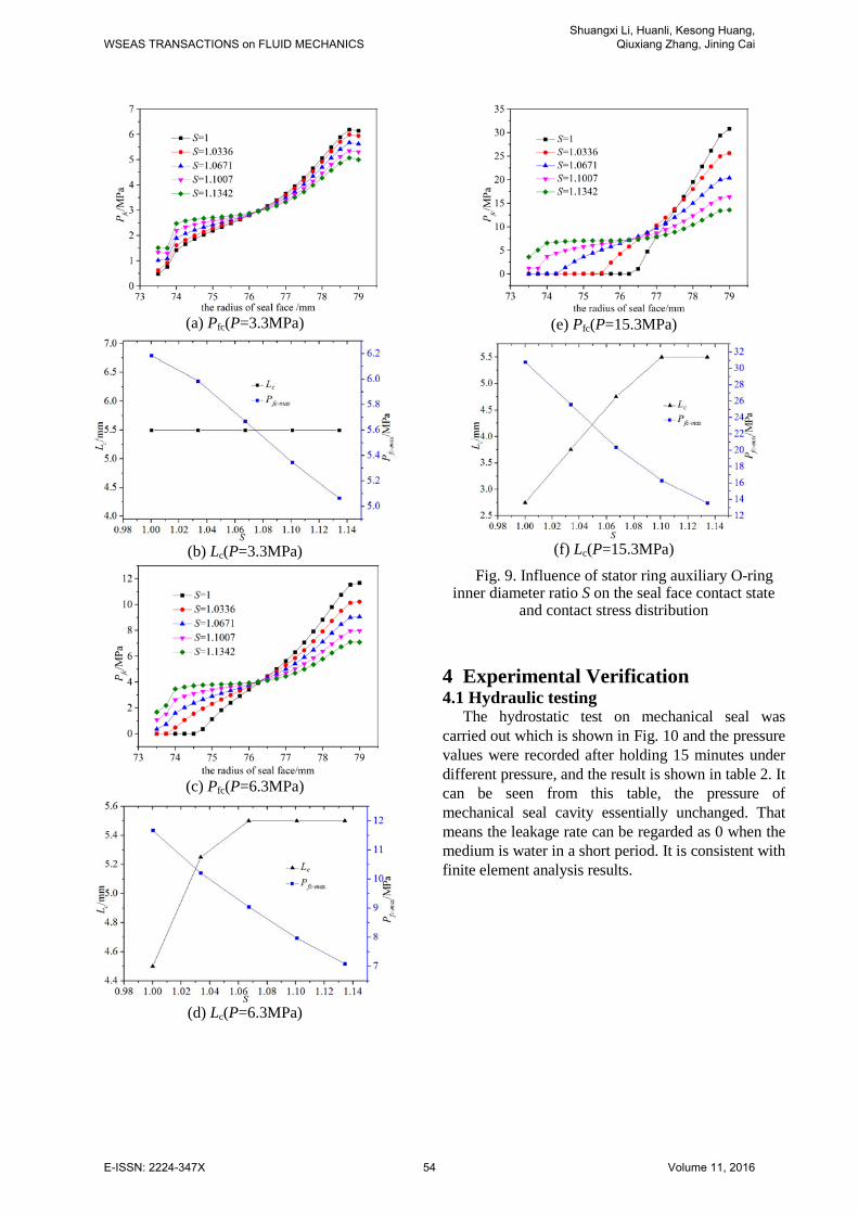
3.4 Stator ring auxiliary O-ring inner diameter ratio S
Stator ring auxiliary O-ring not only supports stator ring, but also is the boundary of stator ring under different working pressure. It has a great influence on the distribution of seal face contact stress Pfc.
The influence of S on seal is shown in Fig. 9. And it shows that the contact stress in the outside area of seal face decreases, while increases in the inside area with the increase of O-ring support diameter. And the contact stress distribution becomes more uniform.
At the same time, the compression area at the bottom of stator ring and turning torque of stator ring decrease. Seal face contact length and contact area of mechanical seal increase while the maximum contact stress on seal face decreases.
WSEAS TRANSACTIONS on FLUID MECHANICSShuangxi Li, Huanli, Kesong Huang,
Qiuxiang Zhang, Jining Cai
E-ISSN: 2224-347X 53 Volume 11, 2016
(a) Pfc(P=3.3MPa)
(b) Lc(P=3.3MPa)
(c) Pfc(P=6.3MPa)
(d) Lc(P=6.3MPa)
(e) Pfc(P=15.3MPa)
(f) Lc(P=15.3MPa)
Fig. 9. Influence of stator ring auxiliary O-ring inner diameter ratio S on the seal face contact state
and contact stress distribution
4 Experimental Verification 4.1 Hydraulic testing
The hydrostatic test on mechanical seal was carried out which is shown in Fig. 10 and the pressure values were recorded after holding 15 minutes under different pressure, and the result is shown in table 2. It can be seen from this table, the pressure of mechanical seal cavity essentially unchanged. That means the leakage rate can be regarded as 0 when the medium is water in a short period. It is consistent with finite element analysis results.
WSEAS TRANSACTIONS on FLUID MECHANICSShuangxi Li, Huanli, Kesong Huang,
Qiuxiang Zhang, Jining Cai
E-ISSN: 2224-347X 54 Volume 11, 2016
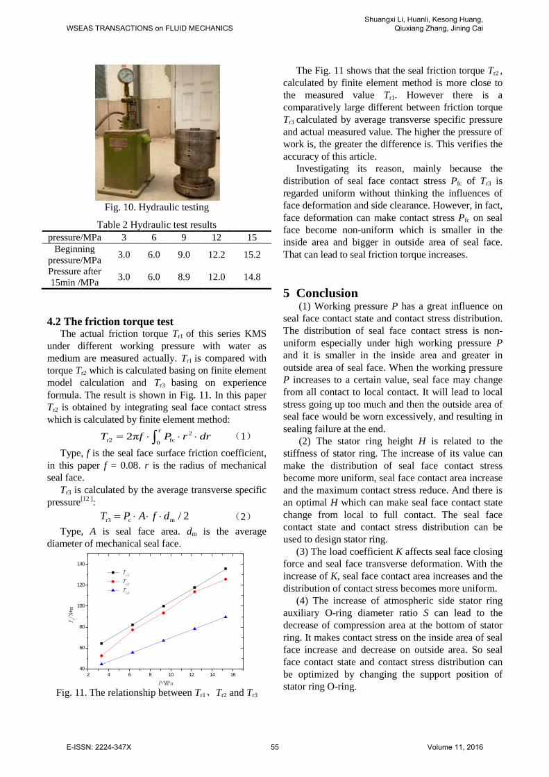
Fig. 10. Hydraulic testing
Table 2 Hydraulic test results pressure/MPa 3 6 9 12 15
Beginning pressure/MPa 3.0 6.0 9.0 12.2 15.2
Pressure after 15min /MPa 3.0 6.0 8.9 12.0 14.8
4.2 The friction torque test
The actual friction torque Tr1 of this series KMS under different working pressure with water as medium are measured actually. Tr1 is compared with torque Tr2 which is calculated basing on finite element model calculation and Tr3 basing on experience formula. The result is shown in Fig. 11. In this paper Tr2 is obtained by integrating seal face contact stress which is calculated by finite element method:
2r2 fc0
2πr
T f P r dr= ⋅ ⋅ ⋅∫ (1)
Type, f is the seal face surface friction coefficient, in this paper f = 0.08. r is the radius of mechanical seal face.
Tr3 is calculated by the average transverse specific pressure[12 ]:
r3 c m / 2T P A f d= ⋅ ⋅ ⋅ (2) Type, A is seal face area. dm is the average
diameter of mechanical seal face.
Fig. 11. The relationship between Tr1、Tr2 and Tr3
The Fig. 11 shows that the seal friction torque Tr2 , calculated by finite element method is more close to the measured value Tr1. However there is a comparatively large different between friction torque Tr3 calculated by average transverse specific pressure and actual measured value. The higher the pressure of work is, the greater the difference is. This verifies the accuracy of this article.
Investigating its reason, mainly because the distribution of seal face contact stress Pfc of Tr3 is regarded uniform without thinking the influences of face deformation and side clearance. However, in fact, face deformation can make contact stress Pfc on seal face become non-uniform which is smaller in the inside area and bigger in outside area of seal face. That can lead to seal friction torque increases.
5 Conclusion (1) Working pressure P has a great influence on
seal face contact state and contact stress distribution. The distribution of seal face contact stress is non-uniform especially under high working pressure P and it is smaller in the inside area and greater in outside area of seal face. When the working pressure P increases to a certain value, seal face may change from all contact to local contact. It will lead to local stress going up too much and then the outside area of seal face would be worn excessively, and resulting in sealing failure at the end.
(2) The stator ring height H is related to the stiffness of stator ring. The increase of its value can make the distribution of seal face contact stress become more uniform, seal face contact area increase and the maximum contact stress reduce. And there is an optimal H which can make seal face contact state change from local to full contact. The seal face contact state and contact stress distribution can be used to design stator ring.
(3) The load coefficient K affects seal face closing force and seal face transverse deformation. With the increase of K, seal face contact area increases and the distribution of contact stress becomes more uniform.
(4) The increase of atmospheric side stator ring auxiliary O-ring diameter ratio S can lead to the decrease of compression area at the bottom of stator ring. It makes contact stress on the inside area of seal face increase and decrease on outside area. So seal face contact state and contact stress distribution can be optimized by changing the support position of stator ring O-ring.
2 4 6 8 10 12 14 1640
60
80
100
120
140
T r/N*m
P/MPa
Tr1
Tr2
Tr3
WSEAS TRANSACTIONS on FLUID MECHANICSShuangxi Li, Huanli, Kesong Huang,
Qiuxiang Zhang, Jining Cai
E-ISSN: 2224-347X 55 Volume 11, 2016
(5) The tests verified that the transverse deformation and side clearance of seal face will make the distribution of contact stress become non-uniform. The higher the pressure is, the greater the difference between the result that calculated with average transverse specific pressure of work and practical result is. So it is very necessary to design and optimize mechanical seal by finite element numerical analysis methods especially under high working pressure.
References [1] Yan Guoping, Liu Zhenglin, Zhu Xueming, et
al. Mechanical Deformation Finite Element Analysis of Ship stern-shaft Sealed Ring[J]. Lubrication Engineering,2007,32(1): 24-26.
[2] Zhuxue Ming Numerical Analysis and Optimization Performance of the mechanical seal [D] Wuhan: Wuhan University of Technology, 2005.
[3] Liao and shore numerical simulation and experimental mechanical seal ring temperature field / stress field research [D] Fuzhou: Fuzhou University, 2005.
[4] Wu Wen mechanical seal face stress numerical study [D] in Xi'an: Xi'an Petroleum University, 2011.
[5] Gao Hao mechanical seal face pressure field / temperature field numerical simulation and experimental study [D] Xi'an: Xi'an Petroleum University, 2012.
[6] Wei Long, Gu boqin, Feng Xiu, et al. Contact fractal model for friction faces of mechanical seals[J]. CIESC Journal,2009, 60(10):2543-2548.
[7] Wei Long, Gu boqin, Sun Jianjun, et al. Optimization of surface fractal dimension of friction pair in mechanical seals[J]. CIESC Journal,2010,61(1): 132-136.
[8] Wei Long, Gu boqin, Liu Qihe, et al. Correction of contact fractal model for friction faces of mechanical seals[J]. CIESC Journal,2013,64(5): 1723-1729.
[9] Ge Peiqi, Chen Lihai, Cheng Jianhui, et al. The Mixed-Friction Calculation Model of Mechanical Face Seals Considering Surface Roughness and Radial Taper[J]. Lubrication Engineering, 2001,05: 14-16.
[10] Yang Huixia, Gu Yongquan. Calculation on the mixed friction performance of contacting mechanical seals considering plastic deformation of asperities[J]. Petro-chemacal Equipment,1998, 27(4): 29-32.
[11] Ding Xuexing, Cheng Xiangping, Du Juan, et al. Numerical simulation of micropolar fluids elastic lubrication with mixed friction in mechanical seal[J]. Journal of Lanzhou University of Technology,2008,34(4): 70-73.
[12] API Standard 682, Shaft Sealing Systems for Centrifugal and Rotary Pumps, Forth Edition[S]. American Petroleum Institute , Washington , D. C. , 2012.
WSEAS TRANSACTIONS on FLUID MECHANICSShuangxi Li, Huanli, Kesong Huang,
Qiuxiang Zhang, Jining Cai
E-ISSN: 2224-347X 56 Volume 11, 2016