Load and stress distribution in screw threads with ... · Load and stress distribution in screw...
11
Journal of Multidisciplinary Engineering Science and Technology (JMEST) ISSN: 2458-9403 Vol. 4 Issue 1, January - 2017 www.jmest.org JMESTN42352017 6523 Load and stress distribution in screw threads with modified washers Carlo Brutti Dept. of Enterprise Engineering University of Rome Tor Vergata Rome, Italy [email protected] Abstract—This paper reports the study of the effects of washer on the strength of bolt-nut connections. We developed a complete theoretical calculation procedure, modifying the classical Maduschka’s approach, to determine the load distribution and then we proposed an assembly of different results, available in bibliography, to evaluate the stress state at the first thread. FE models, properly developed, showed a good agreement with theoretical results. In this way, it was also possible to study how the maximum load and stress reduce by enlarging the internal diameter of the washer, so enhancing the strength and fatigue life by means of a simple and not expensive modification. The improving effect is more effective on the largest size of threaded connection among those examined. Keywords— Screw thread; Load distribution; Stress evaluation; Washer Nomenclature 2 Angle of the thread (°) Dm*=2rL Medium diameter of the bolt and nut (mm) Dmn = 2rmn Medium diameter of nut (mm) Dw = 2rw Washer diameter; i internal, e external De = 2rext External diameter of the nut (mm) Dint = 2rroot Diameter of root of thread (mm) l Pitch of the threads (mm) n Number of threads engaged Flexibility of thread (mm/N); T thread, WN Nut + Washer E,G, Young, Shear modulus (MPa) and Poisson coefficient f Friction factor F Axial force (N) Fo Radial load on the first thread, = F ·tg Fi Force in the ith-thread (N) qi Axial load on the ith-thread (N/mm) i Distribution coeff. of the ith-thread Fi/(F/n) u Radial displacement (mm) w Axial displacement (mm) zr Strain components according to z, r (cylindrical reference system) A * Equivalent bolt cross section (mm²) =Dm* 2 /4 A Equivalent nut cross section (mm²) =De 2 -Dm* 2 )/4 H Radial length of the thread (mm) HN Total height of the nut (mm) I. INTRODUCTION All industrial applications commonly use threaded joints as, for example, in petroleum, transport, mining, automotive, offshore industry and in manufacturing process and more recently in dental implants. The structural behavior of threaded joints is a classic topic in mechanical design. The oldest scientific papers [1][2][3][4] date from the first half of 20th century; they focused correctly the main problems: the not uniform load distribution on the engaged threads, the stress concentration at the root of the threads and under the head of the screw. As reported in [5], failures in screws can be divided: 15% at the fillet under the head, 20% at the first thread and 65% at the first engaged thread. The industrial applications use different types of threaded connections as bolt-nut, threaded piping connection, tie rod connection, shear loaded bolted joint; they are loaded differently and exhibit various problems regarding the structural behavior. This paper refers to the case of bolt and nut equipped by washer.The first problem to solve is the calculation of load distribution along the engaged threads. In their interesting historical review on this problem, Strizhak and Penkov [6] affirm that probably the first scientifically well-stated method is due Joukovsky, that treated the problem as a discrete, statically indeterminate case and concluded that the load distribution follows a decreasing geometrical progression. The Joukovsky solution, originally published in 1902, did not get a general notoriety because the original work was only in Russian. More known is the paper by Den Hartog [2] where he stated that the mating pitches vary, due to the tension of bolt and compression of nut and so this produces a not uniform load distribution along the threads. In 1936 Maduschka [7] developed another discrete method where the threads are regarded as independent circular collars and the contact condition between them requires that the pitch variation due to the external load is equal in bolt and nut. Using the theory of equation in finite differences, Maduschka obtained a closed form solution. All the methods above cited base on a discrete model of the threaded joint but the real features of the joint are, on the contrary, continuous. The first analytical continuous solution is due to I.A. Birger. In his paper, dated 1944 [8], the axial load is distributed according to hyperbolic cosine. Few years later, Sopwith [9] introduced a differential equation that takes into account the continuous variation of the contact condition and consequently the strain field. In the same paper, he examined the methods for improving the strength of the threads trough the optimization of the shape.
Transcript of Load and stress distribution in screw threads with ... · Load and stress distribution in screw...
Journal of Multidisciplinary Engineering Science and Technology (JMEST)
ISSN: 2458-9403
Vol. 4 Issue 1, January - 2017
www.jmest.org
JMESTN42352017 6523
Load and stress distribution in screw threads with modified washers
Carlo Brutti Dept. of Enterprise Engineering University of Rome Tor Vergata
Rome, Italy [email protected]
Abstract—This paper reports the study of the
effects of washer on the strength of bolt-nut connections. We developed a complete theoretical calculation procedure, modifying the classical Maduschka’s approach, to determine the load distribution and then we proposed an assembly of different results, available in bibliography, to evaluate the stress state at the first thread. FE models, properly developed, showed a good agreement with theoretical results. In this way, it was also possible to study how the maximum load and stress reduce by enlarging the internal diameter of the washer, so enhancing the strength and fatigue life by means of a simple and not expensive modification. The improving effect is more effective on the largest size of threaded connection among those examined.
Keywords— Screw thread; Load distribution; Stress evaluation; Washer
Nomenclature 2 Angle of the thread (°) Dm*=2rL Medium diameter of the bolt and nut (mm) Dmn = 2rmn Medium diameter of nut (mm) Dw = 2rw Washer diameter; i internal, e external De = 2rext External diameter of the nut (mm) Dint = 2rroot Diameter of root of thread (mm) l Pitch of the threads (mm) n Number of threads engaged
Flexibility of thread (mm/N); T thread, WN Nut + Washer
E,G, Young, Shear modulus (MPa) and Poisson coefficient
f Friction factor F Axial force (N)
Fo Radial load on the first thread, = F ·tg Fi Force in the ith-thread (N) qi Axial load on the ith-thread (N/mm)
i Distribution coeff. of the ith-thread Fi/(F/n) u Radial displacement (mm) w Axial displacement (mm)
zr Strain components according to z, r (cylindrical reference system)
A* Equivalent bolt cross section (mm²)
=Dm*2/4 A Equivalent nut cross section (mm²)
=De2-Dm*2)/4
H Radial length of the thread (mm) HN Total height of the nut (mm)
I. INTRODUCTION
All industrial applications commonly use threaded joints as, for example, in petroleum, transport, mining, automotive, offshore industry and in manufacturing process and more recently in dental implants. The structural behavior of threaded joints is a classic topic in mechanical design. The oldest scientific papers [1][2][3][4] date from the first half of 20th century; they focused correctly the main problems: the not uniform load distribution on the engaged threads, the stress concentration at the root of the threads and under the head of the screw. As reported in [5], failures in screws can be divided: 15% at the fillet under the head, 20% at the first thread and 65% at the first engaged thread. The industrial applications use different types of threaded connections as bolt-nut, threaded piping connection, tie rod connection, shear loaded bolted joint; they are loaded differently and exhibit various problems regarding the structural behavior. This paper refers to the case of bolt and nut equipped by washer.The first problem to solve is the calculation of load distribution along the engaged threads. In their interesting historical review on this problem, Strizhak and Penkov [6] affirm that probably the first scientifically well-stated method is due Joukovsky, that treated the problem as a discrete, statically indeterminate case and concluded that the load distribution follows a decreasing geometrical progression. The Joukovsky solution, originally published in 1902, did not get a general notoriety because the original work was only in Russian. More known is the paper by Den Hartog [2] where he stated that the mating pitches vary, due to the tension of bolt and compression of nut and so this produces a not uniform load distribution along the threads. In 1936 Maduschka [7] developed another discrete method where the threads are regarded as independent circular collars and the contact condition between them requires that the pitch variation due to the external load is equal in bolt and nut. Using the theory of equation in finite differences, Maduschka obtained a closed form solution. All the methods above cited base on a discrete model of the threaded joint but the real features of the joint are, on the contrary, continuous. The first analytical continuous solution is due to I.A. Birger. In his paper, dated 1944 [8], the axial load is distributed according to hyperbolic cosine. Few years later, Sopwith [9] introduced a differential equation that takes into account the continuous variation of the contact condition and consequently the strain field. In the same paper, he examined the methods for improving the strength of the threads trough the optimization of the shape.

Journal of Multidisciplinary Engineering Science and Technology (JMEST)
ISSN: 2458-9403
Vol. 4 Issue 1, January - 2017
www.jmest.org
JMESTN42352017 6524
After these classical papers, some modification were proposed by other researchers as Miller et al. [10], Kenny e Patterson [11], Zhao [12], to take into account various specific effects. Another numerical contribution is due, more recently, to Mohiuddin et al. [13] that applied the method of the potential-displacement to the determination of the load distribution. Wang and Marshek [14] devoted their attention to the problem of elastic-plastic behavior of the threads. Many researchers focused their attention to an experimental confirmation of the various theoretical methods. For example Brutti and D’eramo [15], using the classical photoelastic results obtained by Hetenyi [4], showed that both the methods of Maduschka and Sopwith give reliable results. Sopwith's theory for the thread load distribution was validated by several studies; among them, Kenny and Patterson [16] used frozen stress photoelastic method in full-scale models of 30 mm ISO nuts and bolts, obtaining good agreement with theory. D’Eramo and Cappa [17] too obtained a good agreement between theoretical and experimental results by strain gauges measures.
Then, in the last decades, the numerical investigation by FE models allowed to study how the actual screw features, neglected in the simplified schemes of theoretical approach, affect the structural behaviour. The bibliography on this particular topic is very large and its exam is beyond the scope of this study. Anyway, it is important to cite, as examples of these types of investigation, Chen and Shih [18] and Su [19], which applied not-linear FE models to study the problem of contact between threads. As mentioned above the structural behavior of the dental implant abutment is treated by several researchers (see, for example [20], [21], [22] and [23]). To complete this overview about the calculation methods of load distribution is possible to refer to the interesting and exhaustive review papers due to Kenny and Patterson [24] and to Mackerle [25].
To improve the strength of threaded connections, many researchers studied how modifying bolt and nut shape can level the load distribution and reduce the stress concentration at the root of the most loaded thread. Regarding the load distribution, Kenny and Patterson [26] studied how it depends on the external shape of the nut and on the nut thread shape [27]. Fetullazade et al. [28] investigated how machining conditions influence the real strength due to residual stresses and strains hardening. Dragoni in several papers [29][30][31][32] studied how the stress distribution modifies due to the geometry and compliance of nut, thread shape and thread pitch. In addition, Fukuoka [33] examined the method for lowering the stress concentration by means of modification of nut shape. Govindu et al. [34] evaluated the classical methods to reduce the stress concentration factor with groove or modifying the shape of the nut. In particular, the modification of the shape of the threads can improve the strength of the connection as shown in the papers [35], [36], [37] and [38]. Due to the helix angle, the threads are inclined and, therefore, a bending moment arises: Wentzel and Huang [39] investigated this problem.
In the last decades, experimental, theoretical and numerical investigations treated the fatigue strength evaluation. We can distinguish three main issues. The first regards measuring experimentally the fatigue strength from a general point of view [40], [41], taking into account the effect of thread modification and examining particular loading conditions and different methods to evaluate the fatigue life [42][43][44][45].
The second issue is to apply the Fracture Mechanics to the strength of threaded connection through the calculation of SIF [49], [50], [51], [52] and [53] or through the calculation of the collapse number of cycles [54], [55], [56] and [57], evaluating the crack growth. The third topic regards the theoretical and numerical evaluation of fatigue life by means of local approach [43][45] or using the available damage models for fatigue assessing .
In this paper, we investigated how load distribution and maximum stress change inserting a washer under the nut and enlarging the internal diameter. Majzoobi et al. [48] studied the importance of the washer on the strength of a bolt-nut connection, but they used a curved spring washer finding that it increases the fatigue life, providing that the springs allow applying correctly the tightening torque in order to produce the required pretension in the bolt. On the contrary, in this study, we used a steel washer with a modification of the internal diameter.
To perform the investigation, we modified the theoretical approach of Maduschka to take into account the effects of the washer and then we developed a method to calculate the state of stress at the root of the thread. To check the accuracy of the methods proposed we used a FE model for ISO M27, comparing the results with the corresponding ones obtained theoretically.
II. WASHER MODIFICATION
The load distribution is strongly depending on the flexibility of threads. As shown in the introduction of this paper, several researchers proposed different modifications of thread and nut to obtain a more regular load distribution (Fig.1 and Fig.2).
In this paper, the same effect is obtained by modifying the internal diameter of the washer as shown Fig. 3.
In fact, the washer introduces the following effects:
- Due to the axial flexibility, all the connections translate along the axis but this does not modify the load distribution because it is equivalent to a rigid vertical displacement.
Due to the eccentricity of the load on the thread, the upper surface of the washer rotates and this alters the flexibility of the thread (see Appendix for the calculation of this effect).
- If rwi≠rroot there is, from the root of the thread up to rwi a flexibility due to the shear deformation of the nut considered as a thick plate (see Appendix for the calculation).
Journal of Multidisciplinary Engineering Science and Technology (JMEST)
ISSN: 2458-9403
Vol. 4 Issue 1, January - 2017
www.jmest.org
JMESTN42352017 6525
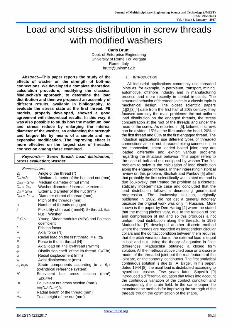
Fig. 1 Load condition of a thread
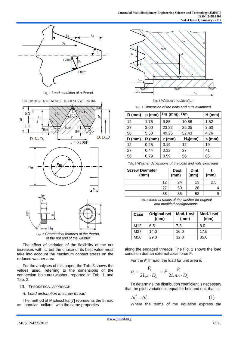
Fig. 2 Geometrical features of the thread,
of the nut and of the washer
The effect of variation of the flexibility of the nut increases with rwi but the choice of its best value must take into account the maximum contact stress on the reduced washer area.
For the analyses of this paper, the Tab. 3 shows the values used, referring to the dimensions of the connection bolt+nut+washer, reported in Tab. 1 and Tab. 2.
III. THEORETICAL APPROACH
A. Load distribution in screw thread
The method of Maduschka [7] represents the thread as annular collars with the same properties
Fig. 3 Washer modification
Tab. 1 Dimension of the bolts and nuts examined
D (mm)
D (mm)
p (mm) Dn (mm) Dm (mm)
H (mm)
12 1.75 9.85 10.86 1.52
27 3.00 23.32 25.05 2.60
56 5.50 49.25 52.43 4.76
D (mm) R (mm) r (mm) HN(mm) s (mm)
12 0.25 0.19 12 19
27 0.44 0.32 27 41
56 0.79 0.59 56 85
Tab. 2 Washer dimensions of the bolts and nuts examined
Screw Diameter (mm)
Dext (mm)
Dint (mm)
t (mm)
12 24 13 2.5
27 50 28 4
56 85 58 9
Tab. 3 Internal radius of the washer for original and modified configurations
along the engaged threads. The Fig. 1 shows the load condition due an external axial force F.
For the ith thread, the load for unit area is
m
i
m
ii
DnLF
DL
Fq
11 22
To determine the distribution coefficient is necessary that the pitch variation is equal for bolt and nut, that is:
(1) *
ii ll
Where the terms of the equation express the
Case Original rwi (mm)
Mod.1 rwi (mm)
Mod.1 rwi (mm)
M12 6.5 7.3 8.0
M27 14.0 16.0 17.5
M56 29.0 32.3 35.0
Dm
L1 L1
Fi Fi/cos
Fitan
Journal of Multidisciplinary Engineering Science and Technology (JMEST)
ISSN: 2458-9403
Vol. 4 Issue 1, January - 2017
www.jmest.org
JMESTN42352017 6526
variation of the pitch between the ith thread and the (i+1)th.
In the following equations, the variables with star refer to the bolt and the others regards the nut. The pitch variation depends on three effects:
- The axial deformation is l*zi for the bolt and lzi for the nut.
- The axial displacement due the elasticity of the thread qih*i for the bolt and qihi for the nut; where qi=qi+1-qi and h* and h are the flexibility for the bolt and nut (see Appendix for calculation).
- The axial displacement due the radial deformation of the bolt and of the thread where
tg·u*i for the bolt and tg·ui for the nut,
where ui=ui+1-ui. In his original paper, Maduschka solved the problem
of the compliance of the threads using the following simplification:
Thh *
In this paper, we calculated the flexibility by means
of a strain energy based approach and then we added the effects on flexibility of the washer, as the Appendix shows.
Finally, we can write the equation
iihqtgulhqtgul iiiziiiz ,
***
,
Then manipulating the last equation, we obtain:
(2) 0**
,
*
, ii
hhquutgl iiiiziz
Where
nEA
F
i
k
iz1
*
*
, 1
nAE
F
i
k
iz1
, 1
nEA
F
i
k
izi1
*
*
,
*
, 1
nEA
F
i
k
izi1
,, 1
21
2
1
*
*
,
* m
i
k
mii
D
nEA
FDu
21
2
1,
m
i
k
mii
D
nAE
FDu
nEA
FDu im
i1
*
*
2
nAE
FDu im
i1
2
Using (2) and all the other equations written above, we obtain:
(3)
11
2
111
1*
*
1
*
1
m
ii
mim
i
k
Dnhh
AA
DnE
FDtg
AAnE
l
Using the same assumption of Maduschka [7] we have:
i
ki
1
Transforming (3), we obtain:
(4) 413211 nGGGG iii
Where
AAEhh
Dtg
DG m
m
11
2
1**1
m
mDAAE
lDtg
EhhG
211
2
1**2
mDG
13
AAEhh
lG
11**4
The (4) is a finite difference equation of the 2th order not homogenous with constant coefficients. The general integral of (4) is
c
ii
i BCBC 21 21
Where B1 and B2 are the solutions of the equation
032
2
1 GBGBG
c is a particular integral of (4):
321
4costGGG
nGc
In addition, the constant C1 and C2 are from the boundary conditions:
i = 1 i-1= 0
i = n-1 i+1= n Then the distribution coefficients have the following formula:
1
222
1
111
iiii
i BBCBBC
The Appendix reports the calculation of flexibility of thread and the effect of washer and nut. So finally we have
* WNTT hh
Journal of Multidisciplinary Engineering Science and Technology (JMEST)
ISSN: 2458-9403
Vol. 4 Issue 1, January - 2017
www.jmest.org
JMESTN42352017 6527
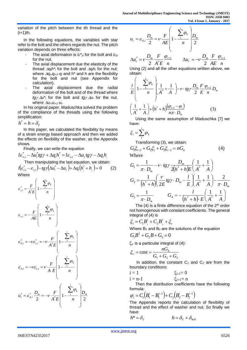
Fig. 4 Stress state at the fillet of the first thread vs. angle
Tab. 4 Load applied to the three bolt/nut washer examples
M12 M27 M56
Load (N) 20735 94138 270177
B. Stress state determination
The process to evaluate theoretically the state of stress at the root of threads is very complex; in fact, there is the superposition of different stress concentration effects on axial, radial and shear stresses. Majzoobi et al. [35] exposed a method to evaluate the stress state around the fillet considering only the stress concentration due to the axial and radial stress. The method bases on the results obtained by Heywood [59] and Pilkey [60]. Unfortunately, the axial and radial stresses are not the unique active components of stress state, but also azimuth and shear stresses contribute to the maximum Von Mises stress, as the Fig. 4 shows. Therefore, in this paper we propose a theoretical approach to obtain a better agreement with the numerical values through calculating the four components of the stress state: radial, azimuthal, axial and shear stresses.
As it is usual in the stress concentration, problems the maximum axial stress is equal to
AxKA
Ft
axax
The value of Kt(Ax) is from the Pilkey’s diagrams [60] for U groove, neglecting the fact that the flanks of the U are inclined of 60° because both Pilkey and Heywood [59] showed that the Kt(Ax) variation is not significant up to this angle. The U groove is not alone but it belongs to a row: it is possible to take into account this using a
modified depth of the notch equal to H*= *· H where
4 ;
5.21
1*
2
int
2
DA
l
H
The nominal radial stress is
RadKA
F
W
bFHFt
o
t
oovRad
11 2
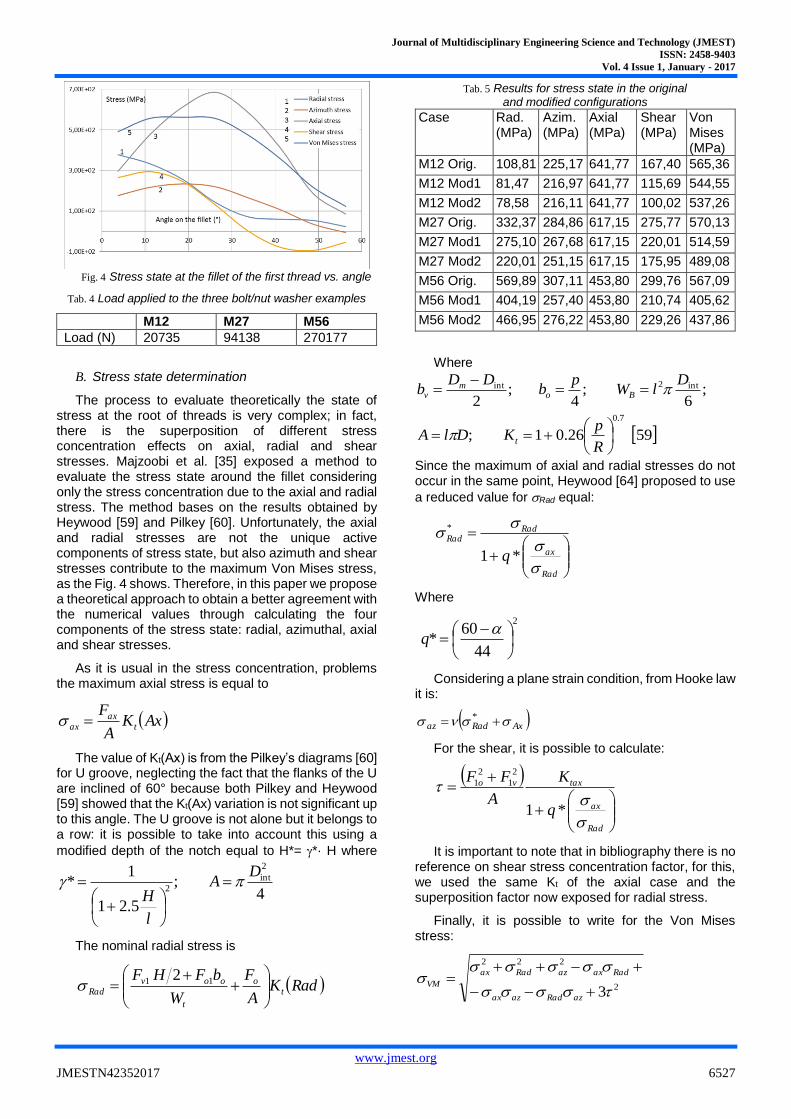
Tab. 5 Results for stress state in the original and modified configurations
Case Rad. (MPa)
Azim. (MPa)
Axial (MPa)
Shear (MPa)
Von Mises (MPa)
M12 Orig. 108,81 225,17 641,77 167,40 565,36
M12 Mod1 81,47 216,97 641,77 115,69 544,55
M12 Mod2 78,58 216,11 641,77 100,02 537,26
M27 Orig. 332,37 284,86 617,15 275,77 570,13
M27 Mod1 275,10 267,68 617,15 220,01 514,59
M27 Mod2 220,01 251,15 617,15 175,95 489,08
M56 Orig. 569,89 307,11 453,80 299,76 567,09
M56 Mod1 404,19 257,40 453,80 210,74 405,62
M56 Mod2 466,95 276,22 453,80 229,26 437,86
Where
59 26.01 ;
;6
;4
;2
7.0
int2int
R
pKDlA
DlW
pb
DDb
t
Bom
v
Since the maximum of axial and radial stresses do not occur in the same point, Heywood [64] proposed to use
a reduced value for Rad equal:
Rad
ax
RadRad
q
*1
*
Where
2
44
60*
q
Considering a plane strain condition, from Hooke law it is:
AxRadaz *
For the shear, it is possible to calculate:
Rad
ax
taxvo
q
K
A
FF
*1
2
1
2
1
It is important to note that in bibliography there is no reference on shear stress concentration factor, for this, we used the same Kt of the axial case and the superposition factor now exposed for radial stress.
Finally, it is possible to write for the Von Mises stress:
2
222
3
azRadazax
RadaxazRadax
VM
Journal of Multidisciplinary Engineering Science and Technology (JMEST)
ISSN: 2458-9403
Vol. 4 Issue 1, January - 2017
www.jmest.org
JMESTN42352017 6528
Using the calculation procedure now exposed it was possible to obtain for all the configurations examined, the results reported in tab.5.
IV. FEM ANALYSIS
To check the accuracy of the theoretical model proposed, a FEM model for NX Nastran was built for M27 bolt and nut assembly. The model employs axisymmetric elements. Therefore, in this model, each thread is a collar neglecting the angle due to the pitch. Clearly, this introduced an error that Majzoobi et al. [48] evaluated as
100*1%222
Dl
DE
For M27 the error E is equal to 0.063% and then negligible.
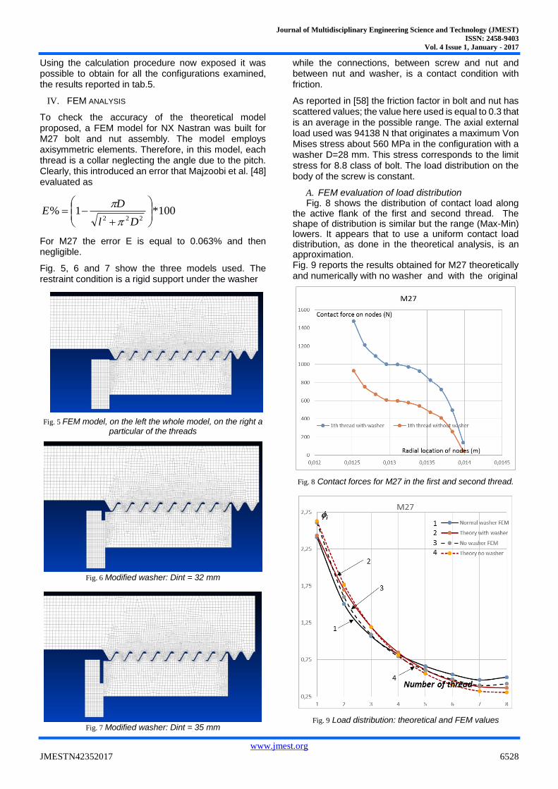
Fig. 5, 6 and 7 show the three models used. The restraint condition is a rigid support under the washer
Fig. 5 FEM model, on the left the whole model, on the right a
particular of the threads
Fig. 6 Modified washer: Dint = 32 mm
Fig. 7 Modified washer: Dint = 35 mm
while the connections, between screw and nut and between nut and washer, is a contact condition with friction.
As reported in [58] the friction factor in bolt and nut has scattered values; the value here used is equal to 0.3 that is an average in the possible range. The axial external load used was 94138 N that originates a maximum Von Mises stress about 560 MPa in the configuration with a washer D=28 mm. This stress corresponds to the limit stress for 8.8 class of bolt. The load distribution on the body of the screw is constant.
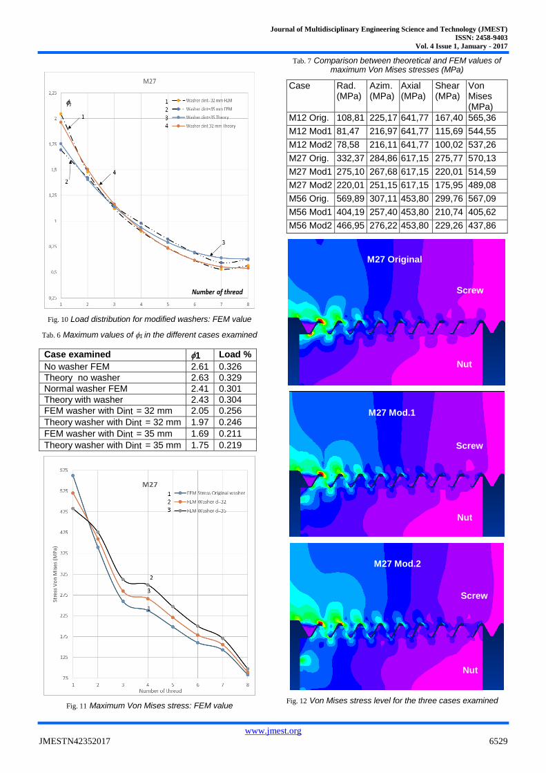
A. FEM evaluation of load distribution Fig. 8 shows the distribution of contact load along
the active flank of the first and second thread. The shape of distribution is similar but the range (Max-Min) lowers. It appears that to use a uniform contact load distribution, as done in the theoretical analysis, is an approximation. Fig. 9 reports the results obtained for M27 theoretically and numerically with no washer and with the original
Fig. 8 Contact forces for M27 in the first and second thread.
Fig. 9 Load distribution: theoretical and FEM values
Journal of Multidisciplinary Engineering Science and Technology (JMEST)
ISSN: 2458-9403
Vol. 4 Issue 1, January - 2017
www.jmest.org
JMESTN42352017 6529
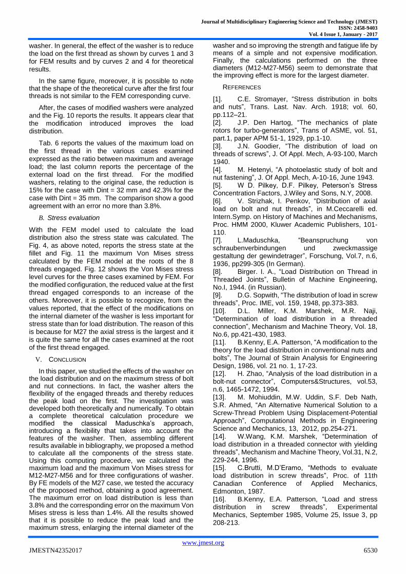
Fig. 10 Load distribution for modified washers: FEM value
Tab. 6 Maximum values of 1 in the different cases examined
Case examined 1 Load %
No washer FEM 2.61 0.326
Theory no washer 2.63 0.329
Normal washer FEM 2.41 0.301
Theory with washer 2.43 0.304
FEM washer with Dint = 32 mm 2.05 0.256
Theory washer with Dint = 32 mm 1.97 0.246
FEM washer with Dint = 35 mm 1.69 0.211
Theory washer with Dint = 35 mm 1.75 0.219
Fig. 11 Maximum Von Mises stress: FEM value
Tab. 7 Comparison between theoretical and FEM values of maximum Von Mises stresses (MPa)
Case Rad. (MPa)
Azim. (MPa)
Axial (MPa)
Shear (MPa)
Von Mises (MPa)
M12 Orig. 108,81 225,17 641,77 167,40 565,36
M12 Mod1 81,47 216,97 641,77 115,69 544,55
M12 Mod2 78,58 216,11 641,77 100,02 537,26
M27 Orig. 332,37 284,86 617,15 275,77 570,13
M27 Mod1 275,10 267,68 617,15 220,01 514,59
M27 Mod2 220,01 251,15 617,15 175,95 489,08
M56 Orig. 569,89 307,11 453,80 299,76 567,09
M56 Mod1 404,19 257,40 453,80 210,74 405,62
M56 Mod2 466,95 276,22 453,80 229,26 437,86
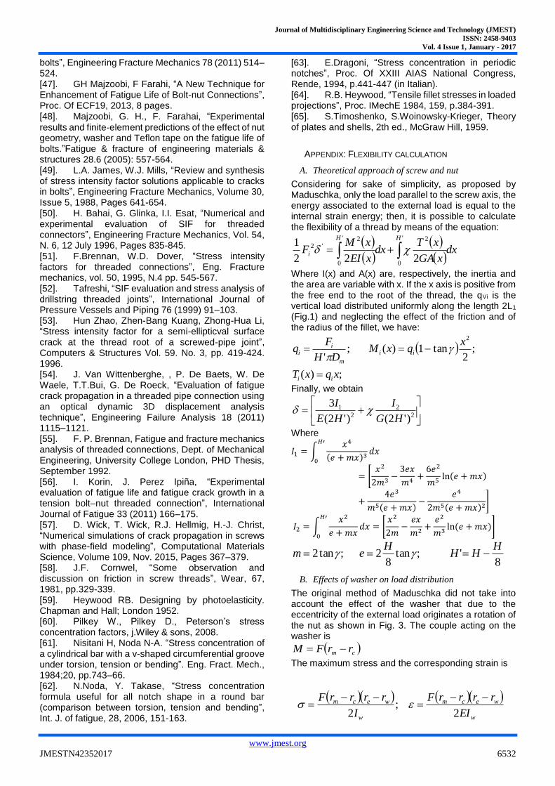
Fig. 12 Von Mises stress level for the three cases examined
M27 Original
M27 Mod.1
M27 Mod.2
Screw
Nut
Screw
Nut
Screw
Nut
Journal of Multidisciplinary Engineering Science and Technology (JMEST)
ISSN: 2458-9403
Vol. 4 Issue 1, January - 2017
www.jmest.org
JMESTN42352017 6530
washer. In general, the effect of the washer is to reduce the load on the first thread as shown by curves 1 and 3 for FEM results and by curves 2 and 4 for theoretical results.
In the same figure, moreover, it is possible to note that the shape of the theoretical curve after the first four threads is not similar to the FEM corresponding curve.
After, the cases of modified washers were analyzed and the Fig. 10 reports the results. It appears clear that the modification introduced improves the load distribution.
Tab. 6 reports the values of the maximum load on the first thread in the various cases examined expressed as the ratio between maximum and average load; the last column reports the percentage of the external load on the first thread. For the modified washers, relating to the original case, the reduction is 15% for the case with Dint = 32 mm and 42.3% for the case with Dint = 35 mm. The comparison show a good agreement with an error no more than 3.8%.
B. Stress evaluation
With the FEM model used to calculate the load distribution also the stress state was calculated. The Fig. 4, as above noted, reports the stress state at the fillet and Fig. 11 the maximum Von Mises stress calculated by the FEM model at the roots of the 8 threads engaged. Fig. 12 shows the Von Mises stress level curves for the three cases examined by FEM. For the modified configuration, the reduced value at the first thread engaged corresponds to an increase of the others. Moreover, it is possible to recognize, from the values reported, that the effect of the modifications on the internal diameter of the washer is less important for stress state than for load distribution. The reason of this is because for M27 the axial stress is the largest and it is quite the same for all the cases examined at the root of the first thread engaged.
V. CONCLUSION
In this paper, we studied the effects of the washer on the load distribution and on the maximum stress of bolt and nut connections. In fact, the washer alters the flexibility of the engaged threads and thereby reduces the peak load on the first. The investigation was developed both theoretically and numerically. To obtain a complete theoretical calculation procedure we modified the classical Maduschka’s approach, introducing a flexibility that takes into account the features of the washer. Then, assembling different results available in bibliography, we proposed a method to calculate all the components of the stress state. Using this computing procedure, we calculated the maximum load and the maximum Von Mises stress for M12-M27-M56 and for three configurations of washer. By FE models of the M27 case, we tested the accuracy of the proposed method, obtaining a good agreement. The maximum error on load distribution is less than 3.8% and the corresponding error on the maximum Von Mises stress is less than 1.4%. All the results showed that it is possible to reduce the peak load and the maximum stress, enlarging the internal diameter of the
washer and so improving the strength and fatigue life by means of a simple and not expensive modification. Finally, the calculations performed on the three diameters (M12-M27-M56) seem to demonstrate that the improving effect is more for the largest diameter.
REFERENCES
[1]. C.E. Stromayer, “Stress distribution in bolts and nuts”, Trans. Last. Nav. Arch. 1918; vol. 60, pp.112–21. [2]. J.P. Den Hartog, “The mechanics of plate rotors for turbo-generators”, Trans of ASME, vol. 51, part.1, paper APM 51-1, 1929, pp.1-10. [3]. J.N. Goodier, “The distribution of load on threads of screws”, J. Of Appl. Mech, A-93-100, March 1940. [4]. M. Hetenyi, “A photoelastic study of bolt and nut fastening”, J. Of Appl. Mech, A-10-16, June 1943. [5]. W D. Pilkey, D.F. Pilkey, Peterson’s Stress Concentration Factors, J.Wiley and Sons, N.Y, 2008. [6]. V. Strizhak, I. Penkov, “Distribution of axial load on bolt and nut threads”, in M.Ceccarelli ed. Intern.Symp. on History of Machines and Mechanisms, Proc. HMM 2000, Kluwer Academic Publishers, 101-110. [7]. L.Maduschka, “Beanspruchung von schraubenverbindungen und zweckmassige gestaltung der gewindetrager”, Forschung, Vol.7, n.6, 1936, pp299-305 (In German). [8]. Birger. I. A., “Load Distribution on Thread in Threaded Joints”, Bulletin of Machine Engineering, No.I, 1944. (in Russian). [9]. D.G. Sopwith, “The distribution of load in screw threads”, Proc. IME, vol. 159, 1948, pp.373-383. [10]. D.L. Miller, K.M. Marshek, M.R. Naji, “Determination of load distribution in a threaded connection”, Mechanism and Machine Theory, Vol. 18, No.6, pp.421-430, 1983. [11]. B.Kenny, E.A. Patterson, “A modification to the theory for the load distribution in conventional nuts and bolts”, The Journal of Strain Analysis for Engineering Design, 1986, vol. 21 no. 1, 17-23. [12]. H. Zhao, “Analysis of the load distribution in a bolt-nut connector”, Computers&Structures, vol.53, n.6, 1465-1472, 1994. [13]. M. Mohiuddin, M.W. Uddin, S.F. Deb Nath, S.R. Ahmed, “An Alternative Numerical Solution to a Screw-Thread Problem Using Displacement-Potential Approach”, Computational Methods in Engineering Science and Mechanics, 13, 2012, pp.254-271. [14]. W.Wang, K.M. Marshek, “Determination of load distribution in a threaded connector with yielding threads”, Mechanism and Machine Theory, Vol.31, N.2, 229-244, 1996. [15]. C.Brutti, M.D’Eramo, “Methods to evaluate load distribution in screw threads”, Proc. of 11th Canadian Conference of Applied Mechanics, Edmonton, 1987. [16]. B.Kenny, E.A. Patterson, “Load and stress distribution in screw threads”, Experimental Mechanics, September 1985, Volume 25, Issue 3, pp 208-213.

Journal of Multidisciplinary Engineering Science and Technology (JMEST)
ISSN: 2458-9403
Vol. 4 Issue 1, January - 2017
www.jmest.org
JMESTN42352017 6531
[17]. D’Eramo M, Cappa P.”An experimental validation of load distribution in screw threads”. Experimental Mechanics, 1991,31, 70 – 75. [18]. J.J. Chen, Y.S. Shih, “A study of the helical effect on the thread connection by three dimensional finite element analysis”, Nuclear Engineering and Design 191 (1999) 109–116. [19]. F. Sun, “Analysis of the Screw Thread Connection Strength Based on Nonlinear Finite Element”, Method Applied Mechanics and Materials, voll. 401-403, 2013, pp.55-58. [20]. O. Eraslan, Ö. İnan, “The effect of thread design on stress distribution in a solid screw implant: a 3D finite element analysis”, Clin. Oral Invest. (2010) 14:411–416. [21]. S. Izumi , T. Yokoyama, A. Iwasaki, S. Sakai, “Three-dimensional finite element analysis of tightening and loosening mechanism of threaded fastener”, Engineering Failure Analysis 12 (2005) 604–615. [22]. S.S. Mandhane, A.P. More, A.P., “A review: Evaluation of design parameters of dental implant abutment” Int. J. of emerging Science and Engineering, vol.2, February 2014, pp. 64-67. [23]. W.Moreira, C. Hermann, J.T. Perreira, J.A.
Balbinoti, R. Tiuossi, “A three ‑ dimensional finite
element study on the stress distribution pattern of two prosthetic abutments for external hexagon implants”, European J. of Dentistry, vol.7, issue 4, Oct-Dec 2013, pp.484-491. [24]. B.Kenny, E.A. Patterson, “The distribution of load and stress in the threads of fasteners – A review”, J. of the Mehanical Behaviour of Materials, vol 2, N. 1-2, 1989, 87-105. [25]. J.Mackerle, “Finite element analysis of fastening and joining: A bibliography (1990–2002)”, International Journal of Pressure Vessels and Piping 80 (2003) 253–271. [26]. B Kenny, E A. Patterson, “Stress analysis of some nut-bolt connections with modifications to the external shape of the nut”, The Journal of Strain Analysis for Engineering Design, vol. 22, 1987, no. 4, 187-193. [27]. B Kenny, E A. Patterson, “Stress analysis of some nut-bolt connections with modifications to the nut thread form”, The Journal of Strain Analysis for Engineering Design, 1985, vol.20, 35-40. [28]. E. Fetullazade, H. K. Akyildiz, S. Saritas, “Effects of the machining conditions on the strain hardening and the residual stresses at the roots of screw threads”, Materials and Design 31 (2010) 2025–2031. [29]. E. Dragoni, “, Effect of nut geometries on screw thread stress distribution: Photoelastic results” The Journal of Strain Analysis for Engineering Design, 1992 vol. 27 no. 1, pp. 1-6. [30]. E. Dragoni, “Effect of nut compliance on screw thread load distribution”, The Journal of Strain Analysis for Engineering Design 1990 vol. 25 no. 3 147-150. [31]. E. Dragoni, “Effect of Thread Shape on Screw Stress Concentration by Photoelastic Measurements”,
J. Offshore Mech. Arct. Eng. 116(4), 228-232 (Nov 01, 1994). [32]. E. Dragoni, “Effect of thread pitch on the fatigue strength of steel bolts”, Proc. of the Institution of Mechanical Engineers, Part C: Journal of Mechanical Engineering Science August 1, 1997 vol. 211 no. 8 591-600. [33]. Fukuoka,T.,“Evaluation of the Method for Lowering Stress Concentration at the Thread Root of Bolted Joints With Modifications of Nut Shape”, ASME Journal of Pressure Vessel Technology, 1997, vol.119, n. 1, pp.1–9. [34]. Govindu N., Jayanand Kumar T. and Venkatesh S., “Design and Optimization of Screwed Fasteners to Reduce Stress Concentration Factor”, J. of Applied Mechanical Engineering, Vol. 4, n.4, 2015. [35]. G.H. Majzoobi, G.H. Farrahi, N. Habibi, “Experimental evaluation of the effect of thread pitch on fatigue life of bolts”, International Journal of Fatigue 27 (2005) 189–196. [36]. J. Van Wittenberghe, J. De Pauw, P. De Baets, W. De Waele, M. A. Wahab, G. De Roeck, “Experimental determination of the fatigue life of modified threaded pipe couplings”, Procedia Engineering 2 (2010) 1849–1858. [37]. S. Mushtaq, N. A. Sheikh, “Experimental Evaluation of the Effect of Thread Angle on the Fatigue Life of Bolts”, Journal of Mechanical and Civil Engineering (IOSR-JMCE), Vol. 7, Issue 1 (May. - Jun. 2013), PP 12-19. [38]. J.Chen, M. Zhang, J. Deng, “Optimal design of triangle fastening screw thread's turn number”, Advanced Materials Research, vol 314-316,2011, pp. 657-660. [39]. H. Wentzel, X. Huang, “Experimental characterization of the bending fatigue strength of threaded fasteners”, International Journal of Fatigue 72 (2015) 102–108. [40]. E. A. Patterson, “A Comparative study of methods for estimating bolt fatigue limit”, Fatigue & Fracture of Engineering Materials & Structures, 13: 59–81, January 1990. [41]. A. Cetin, G. Härkegård, “Fatigue life prediction for large threaded components”, Procedia Engineering 2 (2010) 1225–1233. [42]. M. Ferjani, D. Averbuch, A. Constantinescu, “A computational approach for the fatigue design of threaded connections”, International Journal of Fatigue 33 (2011) 610–623. [43]. R. Schneider, U. Wuttke, C. Berger, “Fatigue analysis of threaded connections using the local strain approach”, Procedia Engineering 2 (2010) 2357–2366. [44]. W. Kim, K. Kawai, H. Koyama, D. Mivazaki, “Fatigue strength and residual stress of groove-rolled products”, J. of Materials Processing Technology, 194, 2007, pp.46-51. [45]. D. Panic, Th. H. Beier, M.Vormwald, “Damage assessment of threaded connections based on an advanced material model and local concepts”, Procedia Engineering 74 ( 2014 ) 119 – 128. [46]. R. Liao, Y. Sun, J. Liu, W. Zhang, “Applicability of damage models for failure analysis of threaded
Journal of Multidisciplinary Engineering Science and Technology (JMEST)
ISSN: 2458-9403
Vol. 4 Issue 1, January - 2017
www.jmest.org
JMESTN42352017 6532
bolts”, Engineering Fracture Mechanics 78 (2011) 514–524. [47]. GH Majzoobi, F Farahi, “A New Technique for Enhancement of Fatigue Life of Bolt-nut Connections”, Proc. Of ECF19, 2013, 8 pages. [48]. Majzoobi, G. H., F. Farahai, “Experimental
results and finite‐element predictions of the effect of nut geometry, washer and Teflon tape on the fatigue life of bolts.”Fatigue & fracture of engineering materials & structures 28.6 (2005): 557-564. [49]. L.A. James, W.J. Mills, “Review and synthesis of stress intensity factor solutions applicable to cracks in bolts”, Engineering Fracture Mechanics, Volume 30, Issue 5, 1988, Pages 641-654. [50]. H. Bahai, G. Glinka, I.I. Esat, “Numerical and experimental evaluation of SIF for threaded connectors”, Engineering Fracture Mechanics, Vol. 54, N. 6, 12 July 1996, Pages 835-845. [51]. F.Brennan, W.D. Dover, “Stress intensity factors for threaded connections”, Eng. Fracture mechanics, vol. 50, 1995, N.4 pp. 545-567. [52]. Tafreshi, “SIF evaluation and stress analysis of drillstring threaded joints”, International Journal of Pressure Vessels and Piping 76 (1999) 91–103. [53]. Hun Zhao, Zhen-Bang Kuang, Zhong-Hua Li, “Stress intensity factor for a semi-ellipticval surface crack at the thread root of a screwed-pipe joint”, Computers & Structures Vol. 59. No. 3, pp. 419-424. 1996. [54]. J. Van Wittenberghe, , P. De Baets, W. De Waele, T.T.Bui, G. De Roeck, “Evaluation of fatigue crack propagation in a threaded pipe connection using an optical dynamic 3D displacement analysis technique”, Engineering Failure Analysis 18 (2011) 1115–1121. [55]. F. P. Brennan, Fatigue and fracture mechanics analysis of threaded connections, Dept. of Mechanical Engineering, University College London, PHD Thesis, September 1992. [56]. I. Korin, J. Perez Ipiña, “Experimental evaluation of fatigue life and fatigue crack growth in a tension bolt–nut threaded connection”, International Journal of Fatigue 33 (2011) 166–175. [57]. D. Wick, T. Wick, R.J. Hellmig, H.-J. Christ, “Numerical simulations of crack propagation in screws with phase-field modeling”, Computational Materials Science, Volume 109, Nov. 2015, Pages 367–379. [58]. J.F. Cornwel, “Some observation and discussion on friction in screw threads”, Wear, 67, 1981, pp.329-339. [59]. Heywood RB. Designing by photoelasticity. Chapman and Hall; London 1952. [60]. Pilkey W., Pilkey D., Peterson’s stress concentration factors, j.Wiley & sons, 2008. [61]. Nisitani H, Noda N-A. “Stress concentration of a cylindrical bar with a v-shaped circumferential groove under torsion, tension or bending”. Eng. Fract. Mech., 1984;20, pp.743–66. [62]. N.Noda, Y. Takase, “Stress concentration formula useful for all notch shape in a round bar (comparison between torsion, tension and bending”, Int. J. of fatigue, 28, 2006, 151-163.
[63]. E.Dragoni, “Stress concentration in periodic notches”, Proc. Of XXIII AIAS National Congress, Rende, 1994, p.441-447 (in Italian). [64]. R.B. Heywood, “Tensile fillet stresses in loaded projections”, Proc. IMechE 1984, 159, p.384-391. [65]. S.Timoshenko, S.Woinowsky-Krieger, Theory of plates and shells, 2th ed., McGraw Hill, 1959.
APPENDIX: FLEXIBILITY CALCULATION
A. Theoretical approach of screw and nut
Considering for sake of simplicity, as proposed by Maduschka, only the load parallel to the screw axis, the energy associated to the external load is equal to the internal strain energy; then, it is possible to calculate the flexibility of a thread by means of the equation:
dxxGA
xTdx
xEI
xMF
HH
i
'
0
2'
0
2'2
222
1
Where I(x) and A(x) are, respectively, the inertia and the area are variable with x. If the x axis is positive from the free end to the root of the thread, the qVi is the vertical load distributed uniformly along the length 2L1 (Fig.1) and neglecting the effect of the friction and of the radius of the fillet, we have:
;)(
;2
tan1)( ;'
2
xqxT
xqxM
DH
Fq
ii
ii
m
ii
Finally, we obtain
2
2
2
1
)'2()'2(
3
HG
I
HE
I
Where
𝐼1 = ∫𝑥4
(𝑒 + 𝑚𝑥)3𝑑𝑥
𝐻′
0
= [𝑥2
2𝑚3−
3𝑒𝑥
𝑚4+
6𝑒2
𝑚5ln(𝑒 + 𝑚𝑥)
+4𝑒3
𝑚5(𝑒 + 𝑚𝑥)−
𝑒4
2𝑚5(𝑒 + 𝑚𝑥)2]
𝐼2 = ∫𝑥2
𝑒 + 𝑚𝑥𝑑𝑥 = [
𝑥2
2𝑚−
𝑒𝑥
𝑚2+
𝑒2
𝑚3ln (𝑒 + 𝑚𝑥)]
𝐻′
0
8' ;tan
82 ;tan2
HHH
Hem
B. Effects of washer on load distribution
The original method of Maduschka did not take into account the effect of the washer that due to the eccentricity of the external load originates a rotation of the nut as shown in Fig. 3. The couple acting on the washer is
cm rrFM
The maximum stress and the corresponding strain is
w
wecm
w
wecm
EI
rrrrF
I
rrrrF
2 ;
2

Journal of Multidisciplinary Engineering Science and Technology (JMEST)
ISSN: 2458-9403
Vol. 4 Issue 1, January - 2017
www.jmest.org
JMESTN42352017 6533
Where
4
44
wew
rrI
Then the maximum vertical displacement is
t
EI
rrrrFw
w
wecm
2
The rotation around rm is
t
EI
rrF
rr
w
w
cm
we
2
The axial displacement at rc is
w
cmL
EI
rrFtw
2
Finally the flexibility due the washer is
w
cmLw
EI
rrt
F
w2
Moreover, when rroot ≠ rw the body of the nut can be considered as an annular thick plate that introduces a shear flexibility to add to the others and that is equal to [65]:
root
wNplate
r
r
D
Hln
18 *
2
Where
2
3
112*
NEH
D .
C. Results
Finally, for the cases examined, we obtained the results exposed in the following table.
Tab. 8 Values of flexibility
Case (mm/N) WN (mm/N) h (mm/N)
M12 Original 5.971·10-12
1.215·10-11
1.812·10-11
M12 Mod1 5.971·10-12
4.126·10-11
4.723·10-11
M12 Mod2 5.971·10-12
7.023·10-11
7.620·10-11
M27 Original 7.463·10-12
3.631·10-12
1.109·10-11
M27 Mod1 7.463·10-12
1.892·10-11
2.639·10-11
M27 Mod2 7.463·10-12
3.222·10-11
3.968·10-11
M56 Original 5.984·10-12
1.781·10-12
7.765·10-12
M56 Mod1 5.984·10-12
9.063·10-12
1.505·10-11
M56 Mod2 5.984·10-12
1.493·10-11
2.091·10-11