· strength of materials control researci* strength . strength of mater 1 als center
Priit Põdra 4. Strength of Components under Torsional Load 1
STRENGTH OF MATERIALSSTRENGTH OF MATERIALS
4. Strength of Components under Torsional Load
4. Strength of Components under Torsional Load
4.1 Structural Model
for Torsion
4.2 Action of
Twisting Loading
4.3Internal Forces
Analysis
4.4Stresses due to Twisting Action
4.5 Shear Stress
Analysis
Mehhanosüsteemide komponentide õppetool
4.6Strength
Calculations
Priit Põdra 4. Strength of Components under Torsional Load 2
STRENGTH OF MATERIALSSTRENGTH OF MATERIALS
4.1. Structural Model for Torsion
4.1. Structural Model for Torsion
Priit Põdra
M
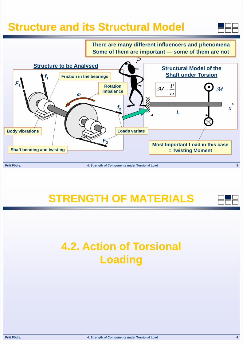
Structural Model of the Shaft under Torsion
Lx
P
M
4. Strength of Components under Torsional Load 3
Structure and its Structural ModelStructure and its Structural Model
F1
f1
F2
f2
Structure to be Analysed
Friction in the bearings
Rotation imbalance
Body vibrations
Shaft bending and twisting
Loads variate
There are many different influencers and phenomenaSome of them are important — some of them are not
Most Important Load in this case = Twisting Moment
Priit Põdra 4. Strength of Components under Torsional Load 4
STRENGTH OF MATERIALSSTRENGTH OF MATERIALS
4.2. Action of Torsional Loading
4.2. Action of Torsional Loading

Priit Põdra 4. Strength of Components under Torsional Load 5
Torsional DeformationTorsional Deformation
Torsional Deformation = rotation of bar' (shaft) cross-sections about the bar axis
Angle of Twist , [rad] =angle of radius relative to its
initial position
Shear Strain (relative angle of twist) , [rad] = angle of generatrix relative to its initial
position
M
Circular Shaft under Torsional Load
Rectangular Shaft under Torsional Load
M
Priit Põdra 4. Strength of Components under Torsional Load 6
Bar’ Load State --- Pure TorsionBar’ Load State --- Pure Torsion
Pure Torsion is applicable only for circular shafts/bars
Bar’ Torsion = (simple) load state of a bar, where: Cross-sections rotate about the bar axis relative to each other;
Axis remains straigth and the bar’ lebgth does not change;
Cross-sections remain paralleel to each ohter and perpendicular to
the axis;
Cross-sections remain planar and theyr shape does not change.
Priit Põdra 4. Strength of Components under Torsional Load 7
STRENGTH OF MATERIALSSTRENGTH OF MATERIALS
4.3. Internal Forces Analysis4.3. Internal Forces Analysis
Priit Põdra 4. Strength of Components under Torsional Load 8
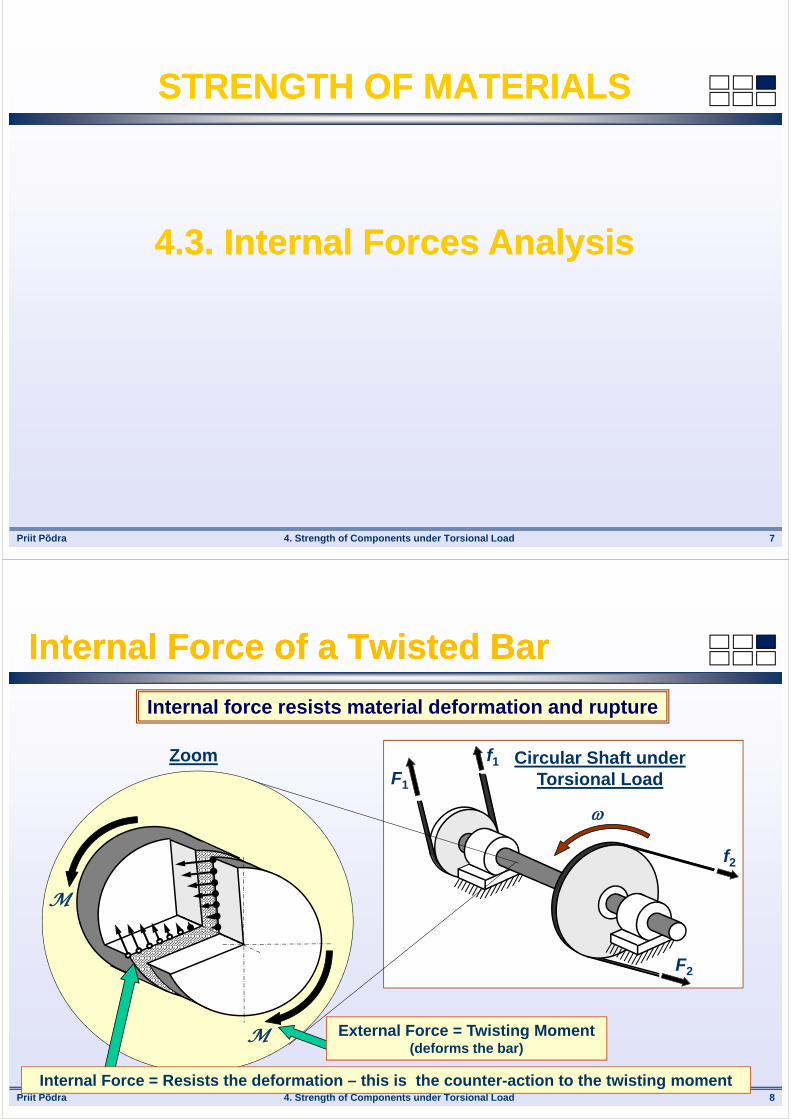
Internal Force of a Twisted BarInternal Force of a Twisted Bar
Internal force resists material deformation and rupture
F1
f1
F2
f2
Circular Shaft under Torsional Load
Zoom
M
M
External Force = Twisting Moment(deforms the bar)
Internal Force = Resists the deformation – this is the counter-action to the twisting moment

Priit Põdra 4. Strength of Components under Torsional Load 9
Internal TorqueInternal Torque
External Force (Load) = Twisting Moment Cross-Section
Particles’ Interaction(Internal) Torque = Resultant
of Particles’ Interaction
Torque T, [Nm] = Resultant of particles interaction on a given (internal) section due to external twisting action
M
T
Priit Põdra 4. Strength of Components under Torsional Load 10
Sign Convention for TorqueSign Convention for Torque
M
M
Section
MM
Section
Shafts Under Twisting Action
MT (+)
Section
M
T (-)
Section
Clockwise = Positive
Looking from the side, that was removed
Counter-Clockwise = Negative
Looking from the side, that was removed

Priit Põdra 4. Strength of Components under Torsional Load 11
Diagram of Torque – Concentrated Loads (1)Diagram of Torque – Concentrated Loads (1)
How are the internal forces distributed in this shaft???Construct the diagramm of Torque distribution
x
xM1 = 2 kNm
M2 = 5 kNm
M3 = 1 kNm
M4 = 4 kNm
Section I
Section II Section III
NB! M = 0
Method of Sections is used in order to analyse internal
forces
The structure must be in equilibrium
Internal force distribution due to concentrated loads is
consistent between these loadsThree sections
must be analysed
Priit Põdra 4. Strength of Components under Torsional Load 12
Diagram of Torque – Concentrated Loads (2)Diagram of Torque – Concentrated Loads (2)
M1 = 2 kNm
M2 = 5 kNmM3 = 1 kNm
M4 = 4 kNm
Free Body Diagram
Section I Section IILeft
M1 = 2 kNm
TI
Section I
Condition of Equilibrium (I)
kNm20 1I MM T
The value of torque TI
does not depend on the location of the section in between
M1 and M2
M1 = 2 kNm
M2 = 5 kNm
TII
Left Section II
Condition of Equilibrium (II)
kNm3250 12II MMM T
The value of torque TII does not depend on the location of the section in between M2 and M3
Priit Põdra
M1 = 2 kNm
M2 = 5 kNm
M3 = 1 kNm
M4 = 4 kNm
2
3
4
4. Strength of Components under Torsional Load 13
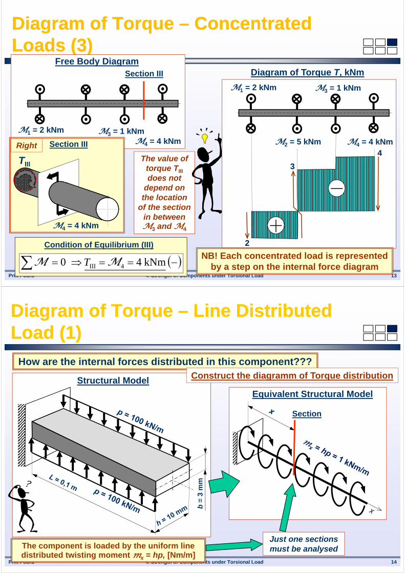
Diagram of Torque – Concentrated Loads (3)Diagram of Torque – Concentrated Loads (3)
Diagram of Torque T, kNm
M1 = 2 kNm
M2 = 5 kNmM3 = 1 kNm
M4 = 4 kNm
Free Body DiagramSection III
Right Section III
x
M4 = 4 kNm
TIII
Condition of Equilibrium (III)
kNm40 4III MM T
The value of torque TIII
does not depend on
the location of the section
in between M3 and M4
NB! Each concentrated load is represented by a step on the internal force diagram
Priit Põdra 4. Strength of Components under Torsional Load 14
Diagram of Torque – Line Distributed Load (1)Diagram of Torque – Line Distributed Load (1)
b =
3 m
m
Structural Model
How are the internal forces distributed in this component???Construct the diagramm of Torque distribution
The component is loaded by the uniform line distributed twisting moment mx = hp, [Nm/m]
Equivalent Structural Model
Section
Just one sections must be analysed

Priit Põdra 4. Strength of Components under Torsional Load 15
Diagram of Torque – Line Distributed Load (2)Diagram of Torque – Line Distributed Load (2)
Condition of Equilibrium
Nm10001001,001,0101000 3 xxxLphxLT xmM
0 then m,1,0
)( Nm100 then ,0 If
xTL
phLxTx
Section
T
Right
M = mx(L - x)
T
Line distributed load can here be replaced
by an equivalent concentarted load
According to the Principle of Saint-Venant
The value of torque T depends linearly on the location of the section
Priit Põdra 4. Strength of Components under Torsional Load 16
Diagram of Torque – Line Distributed Load (3)Diagram of Torque – Line Distributed Load (3)
100
Diagram of Torque T, Nm
Uniform Line Integrated Load
NB! Each uniform line distributed load load is represented by a ramp
on the internal force diagram mxL

Priit Põdra 4. Strength of Components under Torsional Load 17
STRENGTH OF MATERIALSSTRENGTH OF MATERIALS
4.4. Stresses due to Twisting Action
4.4. Stresses due to Twisting Action
Priit Põdra 4. Strength of Components under Torsional Load 18
Shear Stresses in GeneralShear Stresses in General
Shear Stress (aka Tangential Stress):
• acts along the section surface (perpendicular to the norma);
• shows the intensity of internal forces due to the in-plane relative displacements of material layers.
Torsion Cross-Sections are rotated about bar axis
Pure Shear Cross-Sections are linearly
shifted
Torsional Stress
(Pure) Shear Stress
Priit Põdra 4. Strength of Components under Torsional Load 19
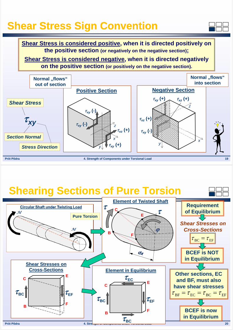
Shear Stress Sign ConventionShear Stress Sign Convention
Shear Stress is considered positive, when it is directed positively on the positive section (or negatively on the negatiive section);
Shear Stress is considered negative, when it is directed negatively on the positive section (or positively on the negatiive section).
xy
Shear Stress
Section Normal
Stress Direction y
z
x
xy (-)
xy (+)
xz (+)xy (-)
Positive Section
y
z
x
xy (+)
xz (+)
xy (-)
Negative Section
xz (+)
Normal „flows“ into section
Normal „flows“ out of section
Priit Põdra 4. Strength of Components under Torsional Load 20
Shearing Sections of Pure TorsionShearing Sections of Pure Torsion
Shear Stresses on Cross-Sections
EFBC
C
BF
E
Shear Stresses on Cross-Sections
BC EF
C
BF
E
Element in Equilibrium
BC EF
BC
EC
Requirement of Equilibrium
BCEF is NOT in Equilibrium
BCEF is now in Equilibrium
Pure Torsion
C
B F
E
Element of Twisted Shaft
Other sections, EC and BF, must also
have shear stresses
EFBCECBF
Priit Põdra 4. Strength of Components under Torsional Load 21
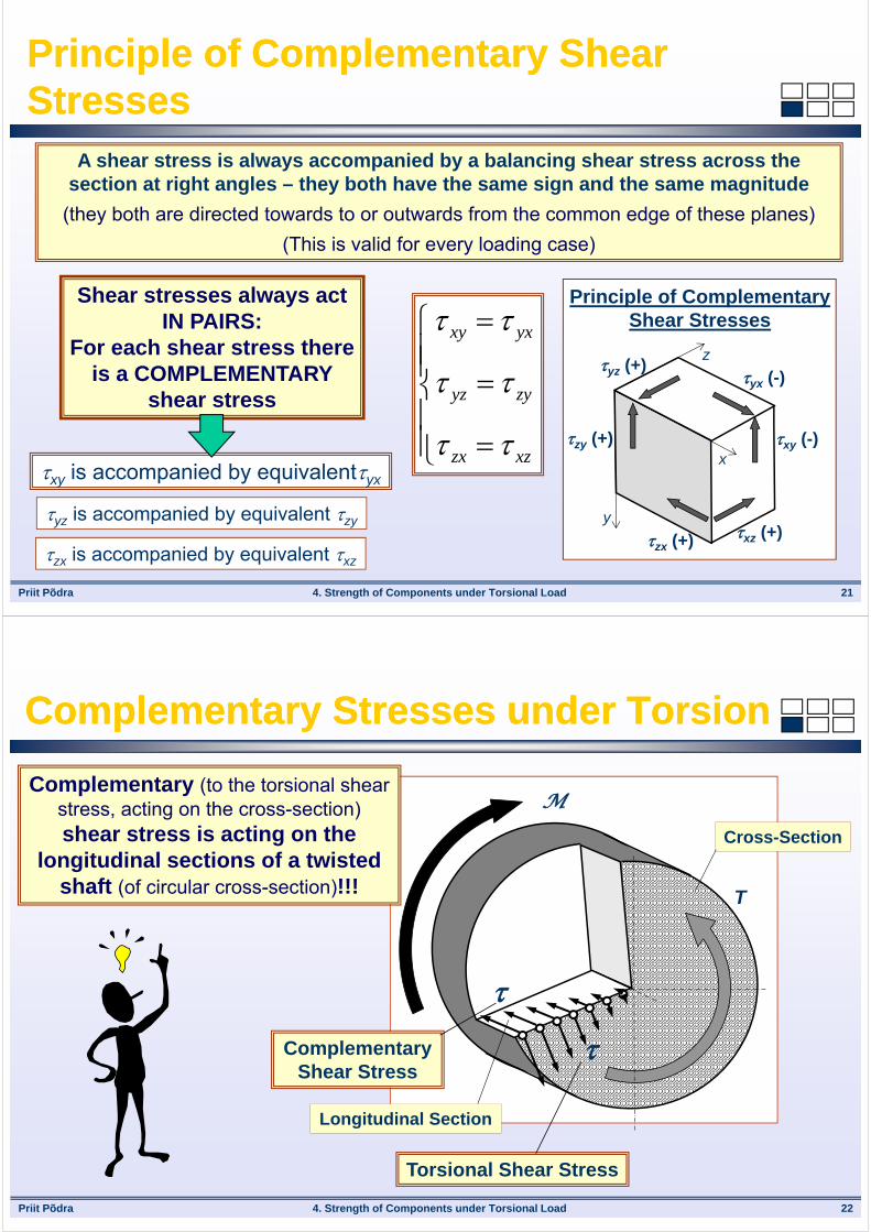
Principle of Complementary Shear StressesPrinciple of Complementary Shear Stresses
A shear stress is always accompanied by a balancing shear stress across the section at right angles – they both have the same sign and the same magnitude
(they both are directed towards to or outwards from the common edge of these planes)
(This is valid for every loading case)
Shear stresses always act IN PAIRS:
For each shear stress there is a COMPLEMENTARY
shear stress
xy is accompanied by equivalentyx
yz is accompanied by equivalent zy
xzzx
zyyz
yxxy
y
z
xzy (+)
yz (+)yx (-)
xy (-)
xz (+)zx (+)
Principle of Complementary Shear Stresses
zx is accompanied by equivalent xz
Priit Põdra 4. Strength of Components under Torsional Load 22
Complementary Stresses under TorsionComplementary Stresses under Torsion
M
T
Cross-Section
Longitudinal Section
Torsional Shear Stress
Complementary Shear Stress
Complementary (to the torsional shear stress, acting on the cross-section) shear stress is acting on the
longitudinal sections of a twisted shaft (of circular cross-section)!!!
Priit Põdra 4. Strength of Components under Torsional Load 23
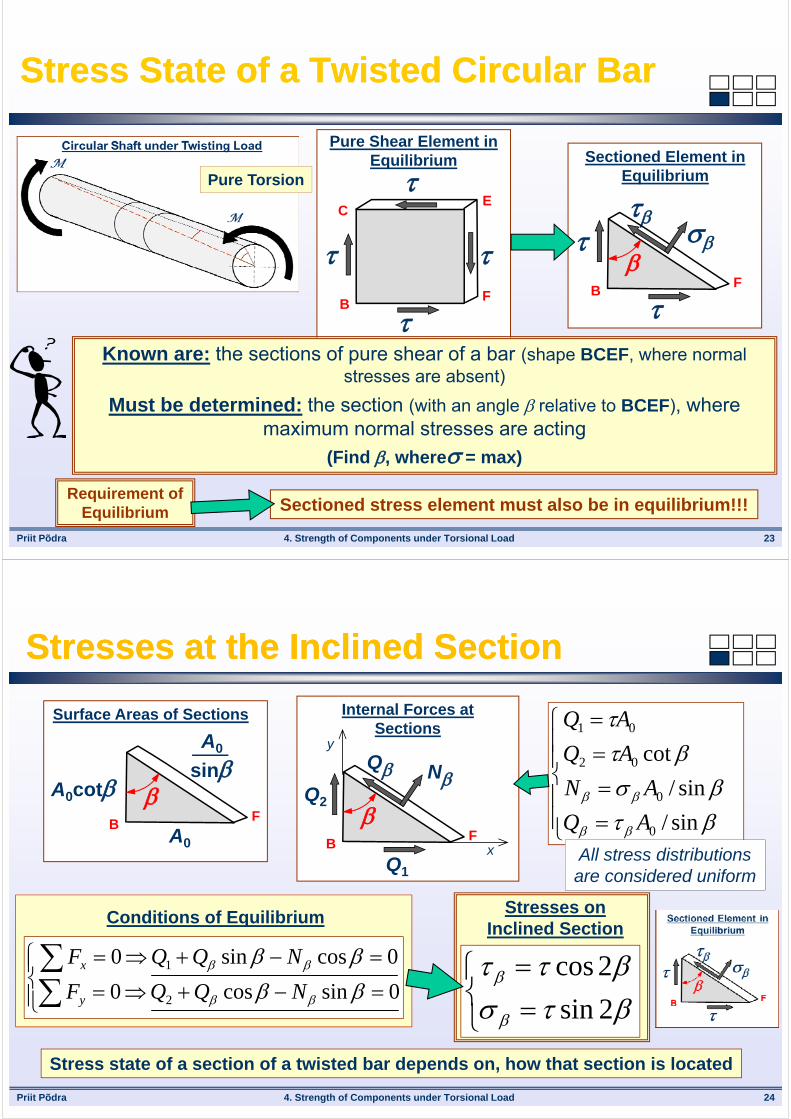
Stress State of a Twisted Circular BarStress State of a Twisted Circular Bar
Requirement of Equilibrium Sectioned stress element must also be in equilibrium!!!
C
BF
E
Pure Shear Element in Equilibrium
BF
Sectioned Element in Equilibrium
Known are: the sections of pure shear of a bar (shape BCEF, where normal stresses are absent)
Must be determined: the section (with an angle relative to BCEF), where maximum normal stresses are acting
(Find , where = max)
Pure Torsion
Priit Põdra 4. Strength of Components under Torsional Load 24
Stresses at the Inclined SectionStresses at the Inclined Section
0sincos 0
0cossin 0
2
1
NQQF
NQQF
y
x
Conditions of EquilibriumStresses on
Inclined Section
2sin
2cos
Stress state of a section of a twisted bar depends on, how that section is located
BF
Surface Areas of Sections
A0
A0cot
A0
sin
BF
Internal Forces at Sections
Q
Q1
Q2
N
x
y
sin/
sin/
cot
0
0
02
01
AQ
AN
AQ
AQ
All stress distributions are considered uniform

Priit Põdra 4. Strength of Components under Torsional Load 25
Normal and Tangential Stresses at Pure TorsionNormal and Tangential Stresses at Pure Torsion
Stresses at Inclined Sections
There is a section, inclined by 45 about the purely torsioned bar’ cross-section, where the shear is absent and the tension is maximum
2sin
2cosPure Torsion
= 0 = /6 = 30 = /4 = 45 = /3 = 60 = /2 = 90
= = 0,5 = 0 = 0,5 = = 0 = 0,87 = = 0,87 = 0
Priit Põdra 4. Strength of Components under Torsional Load 26
Bar’ failure Modes under TorsionBar’ failure Modes under Torsion
Pure Torsion
Failure at the Cross-Section (Steel)
Failure at the Longitudinal Sections (Wood)
Failure at the Inclined Section (Cast iron)
45
Shear strength is lower than
tensile strength
Shear strength along the fiber is lower than that across the fiber
Shear strength is higher than
tensile strength

Priit Põdra 4. Strength of Components under Torsional Load 27
STRENGTH OF MATERIALSSTRENGTH OF MATERIALS
4.5. Shear Stress Analysis4.5. Shear Stress Analysis
Priit Põdra 4. Strength of Components under Torsional Load 28
Possibility of Shear Stresses on the Edge of SectionPossibility of Shear Stresses on the Edge of Section
Tangential Component tComplementary
Stress’n NB! There could be no stresses at the
external surfaces????
NB! Remember the principle of Complementary Shear Stresses
Assumed Shear Stress at the external corner of Cross-Section
A
C
t1
t2
’t1 ’t2
A
C
t n
’n
Assumed Shear Stress at the edge of Cross-Section
can be divided
Normal Component n Tangential Component t1
Tangential Component t2Complementary
Stress’t1Complementary
Stress’t2
Both appears at the external
surface of a barAppears at the
external surface of a bar

Priit Põdra
A
C
t
Section under torsional/shearing action
External CornerTangent to the Edge
4. Strength of Components under Torsional Load 29
Special Features of Shear Stress DistributionSpecial Features of Shear Stress Distribution
There could be no stresses at the bar’ external surfaces
Shear stress at the edge of a section can only be directed along
the edge tangent at that point
There could not be any shear stress acting at the
external corner point of the edge (there always = 0)
Assuming, that:The shape of the bar stays intact
The shape of the cross-section stays intact
Priit Põdra 4. Strength of Components under Torsional Load 30
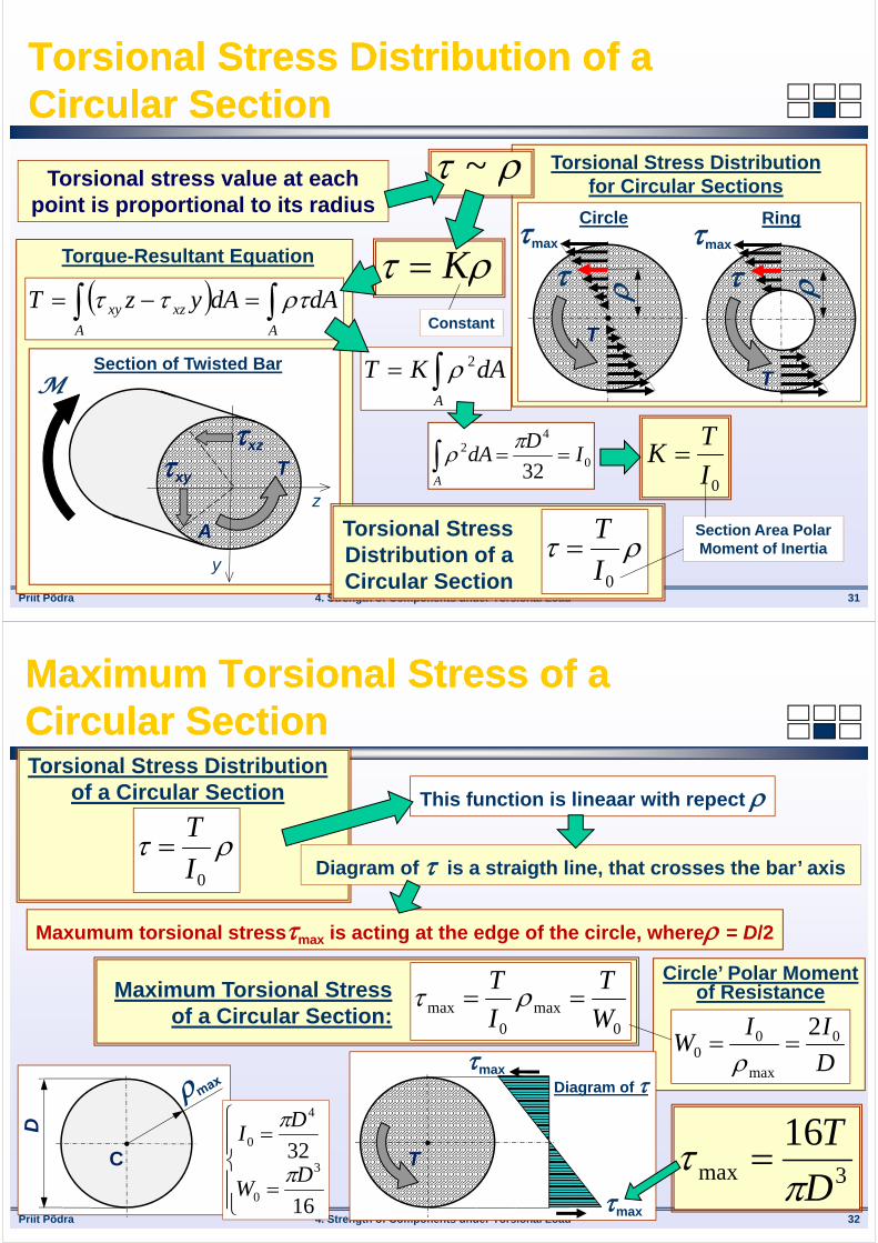
Torsional Stresses of a Circular BarTorsional Stresses of a Circular Bar
Bar deforms/twists due to the loading
Equal elements of an uniform bar deform equally
(The bar deforms uniformly)
The shape and volume of elements do not change
Shear strain values (and deformations) are
proportional to the values of respective radii
Hooke’s Law for Shear:
G ~
T
Element of Twisted Bar
~
Priit Põdra
Circle
max
T
max
T
T
Ring
Torsional Stress Distribution for Circular Sections
Torque-Resultant Equation
AA
xzxy dAdAyzT
Txy
Section of Twisted Bar
z
y
M
xz
A
4. Strength of Components under Torsional Load 31
Torsional Stress Distribution of a Circular SectionTorsional Stress Distribution of a Circular Section
~Torsional stress value at each point is proportional to its radius
KConstant
A
dAKT 2
0
42
32I
DdA
A
0I
TK
Torsional Stress Distribution of a Circular Section
0I
T
Section Area Polar Moment of Inertia
Priit Põdra 4. Strength of Components under Torsional Load 32
Maximum Torsional Stress of a Circular SectionMaximum Torsional Stress of a Circular Section
This function is lineaar with repect
Maxumum torsional stressmax is acting at the edge of the circle, where = D/2
Maximum Torsional Stress of a Circular Section:
0max
0max W
T
I
T
D
IIW 0
max
00
2
Circle’ Polar Moment of Resistance
3max
16
D
T
Torsional Stress Distribution of a Circular Section
0I
T
Diagram of is a straigth line, that crosses the bar’ axis
C
D
16
323
0
4
0
DW
DI
max
T
max
Diagram of
Priit Põdra 4. Strength of Components under Torsional Load 33
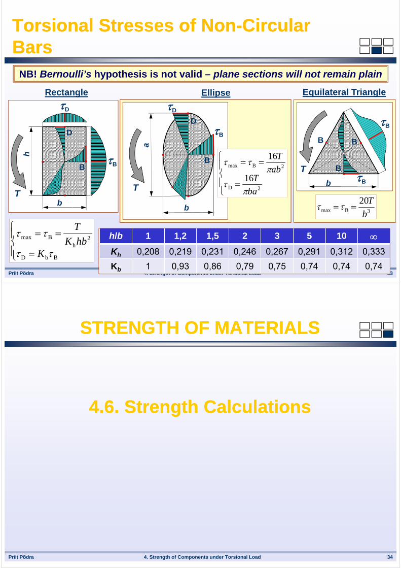
Torsional Stresses of Non-Circular BarsTorsional Stresses of Non-Circular Bars
3Bmax
20
b
T
Equilateral TriangleEllipseRectangle
BbD
2h
Bmax
KhbK
T
NB! Bernoulli’s hypothesis is not valid – plane sections will not remain plain
B
D
b
h
T
B
D
B
D
b
a
T
B
D
2D
2Bmax
16
16
ba
Tab
T
b
TB
B
BB
B
h/b 1 1,2 1,5 2 3 5 10 Kh 0,208 0,219 0,231 0,246 0,267 0,291 0,312 0,333
Kb 1 0,93 0,86 0,79 0,75 0,74 0,74 0,74
Priit Põdra 4. Strength of Components under Torsional Load 34
STRENGTH OF MATERIALSSTRENGTH OF MATERIALS
4.6. Strength Calculations4.6. Strength Calculations
Priit Põdra
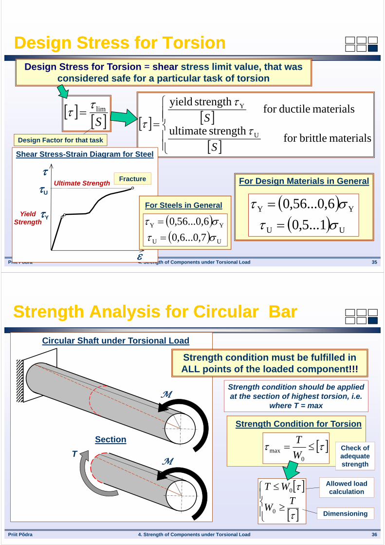
For Design Materials in General
UU
YY
1...5,0
6,0...56,0
4. Strength of Components under Torsional Load 35
Design Stress for TorsionDesign Stress for TorsionDesign Stress for Torsion = shear stress limit value, that was
considered safe for a particular task of torsion
Slim
materials brittlefor
strength ultimate
materials ductilefor strength yield
U
Y
S
S
Shear Stress-Strain Diagram for Steel
Yield Strength
Ultimate Strength
U
Y
Fracture
For Steels in General
UU
YY
7,0...6,0
6,0...56,0
Design Factor for that task
Priit Põdra 4. Strength of Components under Torsional Load 36
Strength Analysis for Circular BarStrength Analysis for Circular Bar
Strength condition should be applied at the section of highest torsion, i.e.
where T = max
0
max W
T
Strength Condition for Torsion
M
Circular Shaft under Torsional Load
MT
Section
Strength condition must be fulfilled in ALL points of the loaded component!!!
T
W
WT
0
0
Check of adequate strength
Allowed load calculation
Dimensioning

Priit Põdra 4. Strength of Components under Torsional Load 37
Dimensioning of Circular BarDimensioning of Circular Bar
max
T max
Diagram of D
16
3
0
DW
316
T
D
Circular Cross-Section
max
T max
Diagram of D
Ring Cross-Section
d
43
0 116
cD
W
341
16
c
TD
D
dc
All cross-section points have
torsional stress
The most critical points of a circular section are located on its edge
All points of the edge have equal criticality
Priit Põdra 4. Strength of Components under Torsional Load 38
Strength Analysis for Rectangular BarStrength Analysis for Rectangular Bar
Strength condition should be applied at the section of highest torsion, i.e. where T = max
Strength Condition for Torsion
Strength condition must be fulfilled in ALL points of the loaded component!!!
Check of adequate strength
Allowed load calculation
Dimensioning
2
hmax hbK
T
2hhbKT
Rectangular Shaft under Torsional Load
M
SectionT
M
b
h

Priit Põdra 4. Strength of Components under Torsional Load 39
Dimensioning of Rectangular BarDimensioning of Rectangular Bar
Rectangular Cross-Section
b
h
T
max
Diagrams of
b
hc
3
h
2
K
Tch
Square Cross-Sectiona
T
max
Diagrams of max
3
208.0 T
a The most critical points of a rectangular section are located on its edge, in the
middle of the longest sides
Symmetrical points of the edge have equal criticality
Priit Põdra 4. Strength of Components under Torsional Load 40
Dimensioning – Concentrated Loads (1)Dimensioning – Concentrated Loads (1)
M1 = 2 kNm
M2 = 5 kNm
M3 = 1 kNm
M4 = 4 kNm
2
3
4
Diagram of T, [kNm]
Shaft Cross-Section and Torsional Stress Distribution
From previous
Material:
Steel, [] = 60 MPa
Strength Condition
Calculate the required diameter of the twisted uniform circular shaft!
B C E G
Priit Põdra 4. Strength of Components under Torsional Load 41
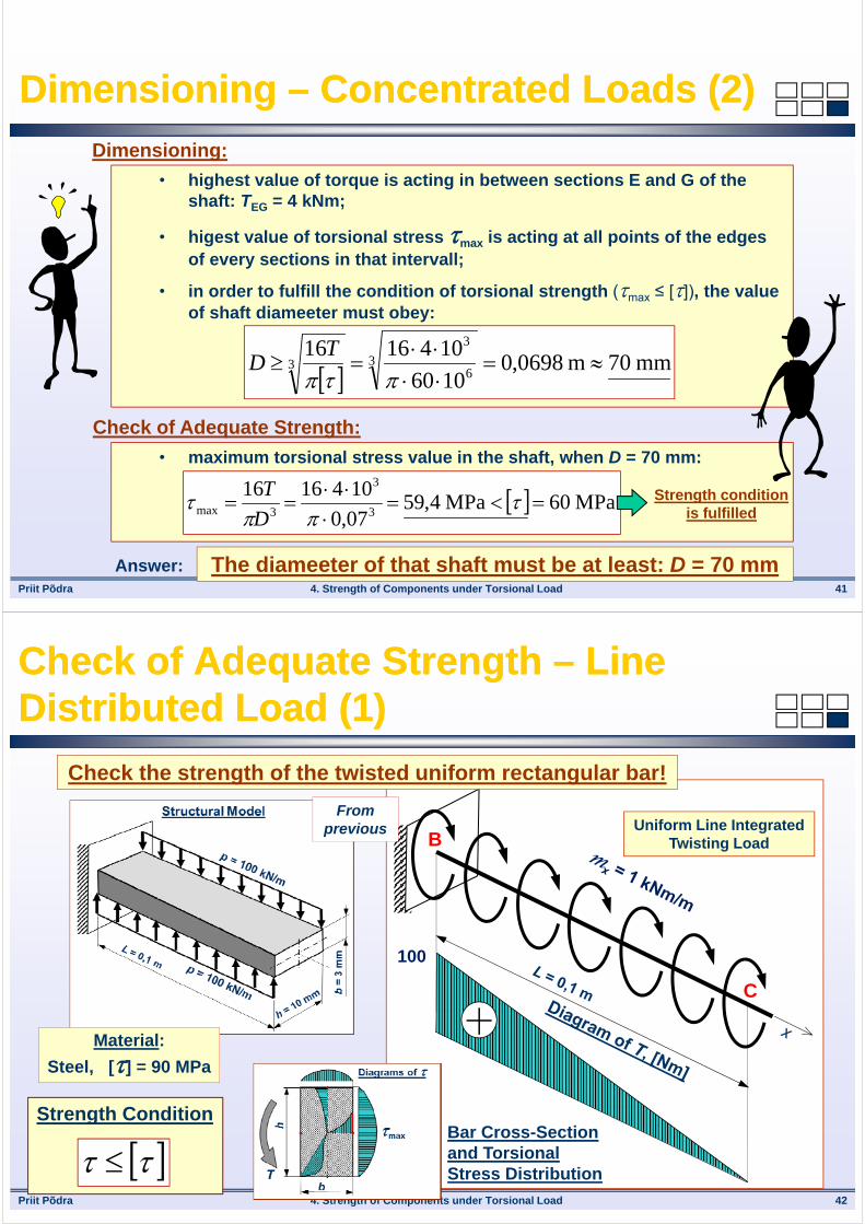
Dimensioning – Concentrated Loads (2)Dimensioning – Concentrated Loads (2)
Dimensioning:
• highest value of torque is acting in between sections E and G of the shaft: TEG = 4 kNm;
• higest value of torsional stress max is acting at all points of the edges of every sections in that intervall;
• in order to fulfill the condition of torsional strength (max ≤ []), the value of shaft diameeter must obey:
mm70m0698,01060
10416163
6
3
3
TD
Check of Adequate Strength:
• maximum torsional stress value in the shaft, when D = 70 mm:
MPa60MPa4,5907,0
10416163
3
3max
D
T Strength condition is fulfilled
The diameeter of that shaft must be at least: D = 70 mmAnswer:
Priit Põdra 4. Strength of Components under Torsional Load 42
Check of Adequate Strength – Line Distributed Load (1)Check of Adequate Strength – Line Distributed Load (1)
100
Uniform Line Integrated Twisting Load
Check the strength of the twisted uniform rectangular bar!
Material:
Steel, [] = 90 MPa
Strength Condition
From previous
Bar Cross-Section and Torsional Stress Distribution
B
C
Priit Põdra 4. Strength of Components under Torsional Load 43
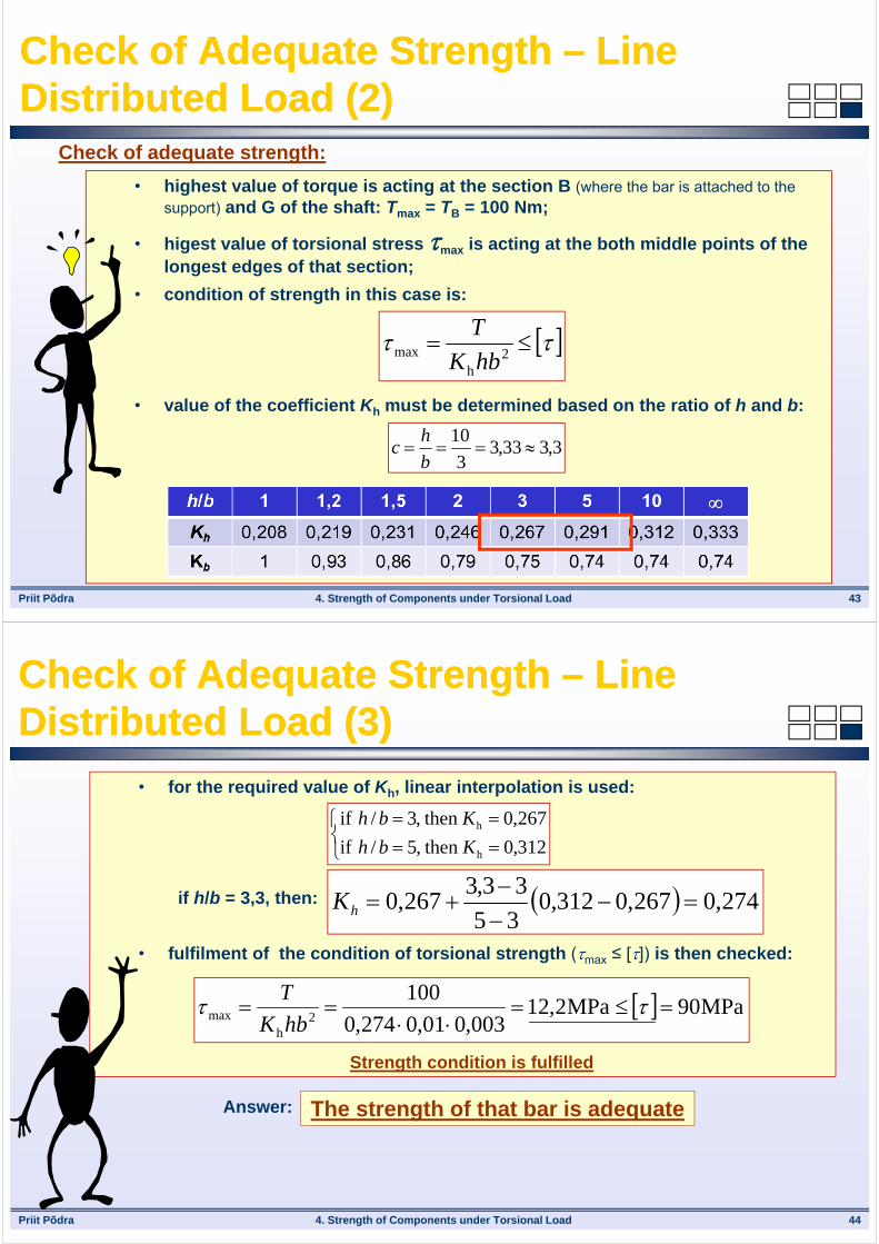
Check of Adequate Strength – Line Distributed Load (2)Check of Adequate Strength – Line Distributed Load (2)
Check of adequate strength:
• highest value of torque is acting at the section B (where the bar is attached to the support) and G of the shaft: Tmax = TB = 100 Nm;
• higest value of torsional stress max is acting at the both middle points of the longest edges of that section;
• condition of strength in this case is:
• value of the coefficient Kh must be determined based on the ratio of h and b:
2
hmax hbK
T
3,333,33
10
b
hc
Priit Põdra 4. Strength of Components under Torsional Load 44
Check of Adequate Strength – Line Distributed Load (3)Check of Adequate Strength – Line Distributed Load (3)
• for the required value of Kh, linear interpolation is used:
if h/b = 3,3, then:
• fulfilment of the condition of torsional strength (max ≤ []) is then checked:
312,0 then ,5/ if
267,0 then ,3/ if
h
h
Kbh
Kbh
274,0267,0312,035
33,3267,0
hK
MPa90MPa2,12003,001,0274,0
1002
hmax
hbK
T
Strength condition is fulfilled
The strength of that bar is adequateAnswer:

Priit Põdra 4. Strength of Components under Torsional Load 45
STRENGTH OF MATERIALSSTRENGTH OF MATERIALS
THANK YOU!THANK YOU!
Questions, please?
Mehhanosüsteemide komponentide õppetool