· strength of materials control researci* strength . strength of mater 1 als center
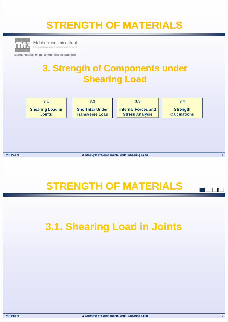
Priit Põdra 3. Strength of Components under Shearing Load 1
STRENGTH OF MATERIALSSTRENGTH OF MATERIALS
3. Strength of Components under Shearing Load
3. Strength of Components under Shearing Load
Mehhanosüsteemide komponentide õppetool
3.1
Shearing Load in Joints
3.2
Short Bar Under Transverse Load
3.3
Internal Forces and Stress Analysis
3.4
Strength Calculations
Priit Põdra 3. Strength of Components under Shearing Load 2
STRENGTH OF MATERIALSSTRENGTH OF MATERIALS
3.1. Shearing Load in Joints3.1. Shearing Load in Joints

Priit Põdra
Force
Bar
Shearing Load
3. Strength of Components under Shearing Load 3
Shearing Load Action in GeneralShearing Load Action in General
In transverse direction to the bar’ axis
Zoom
Very short distance ---bending is irrelevant
Cut or „Sheared“ Bar
Cutting Surface
As if cut using scissors or cutter
Shear Area
Priit Põdra 3. Strength of Components under Shearing Load 4
Components under Shearing Action Components under Shearing Action
Pinned Joint
F
Pins
Riveted Joint
F F
Rivets
Welded Joint
F WeldmentBearing Support
F
Axle
Roller
Belt
Pinned Joint
Pin
F F

Priit Põdra 3. Strength of Components under Shearing Load 5
STRENGTH OF MATERIALSSTRENGTH OF MATERIALS
3.2. Short Bar Under Transverse Load3.2. Short Bar Under Transverse Load
Priit Põdra 3. Strength of Components under Shearing Load 6
Shearing DeformationShearing Deformation
Short Bar under Transverse ActionShearing Action Area
Bending deformation is negligibly small
F
Axle
Roller
BeltHousing
Shear Area
ZoomRoller
Axle
Transverse loading to the Axle
Axle material parallel internal layers
(surfaces) slide past each other

Priit Põdra 3. Strength of Components under Shearing Load 7
Shearing Sections of Pure ShearShearing Sections of Pure Shear
Shear Stresses on Cross-Sections
EFBC
Other sections, EC and BF, must also
have shear stresses
EFBCECBF
C
BF
E
Shear Stresses on Cross-Sections
BC EF
C
BF
E
Element in Equilibrium
BC EF
BC
EC
C
B F
E
Requirement of Equilibrium
BCEF is NOT in Equilibrium
BCEF is now in Equilibrium
Priit Põdra 3. Strength of Components under Shearing Load 8
Principle of Complementary Shear StressesPrinciple of Complementary Shear Stresses
A shear stress is always accompanied by a balancing shear stress across the section at right angles – they both have the same sign and the same magnitude
(they both are directed towards to or outwards from the common edge of these planes)
(This is valid for every laoding case)
Shear stresses always act IN PAIRS:
For each shear stress there is a COMPLEMENTARY
shear stress
xy is accompanied by equivalentyx
yz is accompanied by equivalent zy
xzzx
zyyz
yxxy
y
z
xzy (+)
yz (+)yx (-)
xy (-)
xz (+)zx (+)
Principle of Complementary Shear Stresses
zx is accompanied by equivalent xz

Priit Põdra 3. Strength of Components under Shearing Load 9
Shearing Deformations of a Short BarShearing Deformations of a Short Bar
Structural Model of the Bar and Transverse Deformation
NB! Principle of complementary Shear Stresses
Shear Strains
uvxy vuyx
yxxyyxxy Total Shear Strain
u
v
u
v
xy
yx
y
x
F
v
v
y
xxy
Shear Stress in Cross-Section
uuy
x
yx
Complementary Shear Stress
Priit Põdra 3. Strength of Components under Shearing Load
Bearing Stress in the JointBearing Stress in the Joint
Compressive stresses are acting in the bearing area
Compressive deformations
F
Axle
Roller
BeltHousing
Shear Area Bearing Action Area
y
z
F
Roller
Belt
Belt loading action is transferred to the axle through the roller-axle
bearing/contact surface
NB! There is a danger of bearing surface damage in the joint
10

Priit Põdra 3. Strength of Components under Shearing Load 11
STRENGTH OF MATERIALSSTRENGTH OF MATERIALS
3.3. Internal Forces and Stress Analysis3.3. Internal Forces and Stress Analysis
Priit Põdra 3. Strength of Components under Shearing Load 12
Internal Forces of a Bar under ShearInternal Forces of a Bar under Shear
F
1st Shear Area
2nd Shear Area
Mechanical system
loaded by gravity
Bar under transverse loading: Two shear areas
in this case
Load is divided equally between two shear areas
221
FFF
Acts transversly to the bar’ axis
External Force F2
F2
Internal Force
Load to the 2nd
shear area
Interaction between the particles of a loaded bar,
resisting the shearing deformations and fracture
Is a result of the load F action
Zoom

Priit Põdra 3. Strength of Components under Shearing Load 13
Shear ForceShear Force
Shear Force Q, [N] = resultant of the particles’ translatory and in-plane
interaction on a given section
Cross-Section
External Force = Load F
Q
Interaction between the particles
Shear Force
Transverse to the bar’ axis
Resultant of the particles’ interaction
forces due to transverse loading
In English/US literature usually denoted with V
Priit Põdra 3. Strength of Components under Shearing Load 14
Shear Force at the Bar’ Cross-SectionShear Force at the Bar’ Cross-Section
Shear forces (in the bar’ shear areas) are determined using the method of sections
Shear Areas
Bar
Section I Section II
F
Bar under Shearing Action
Bar
F
F1 F2
Active Load
Support Reactions
Free Body Diagram
21 FFF
Shear Forces in Sections
QI = F1
F1Section I
QII = F2
F2Section II
m = 2
In the cases of symmetrical loading pattern, the shear forces at sections are all equal
m
FQQQQ m ...III
Shear Force at a Section
Number of Equally Loaded Sections
Priit Põdra 3. Strength of Components under Shearing Load 15
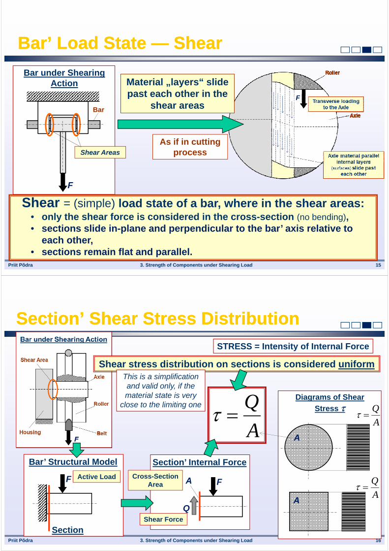
Bar’ Load State — ShearBar’ Load State — Shear
F
Shear Areas
Bar
F
Bar under Shearing Action Material „layers“ slide
past each other in the shear areas
As if in cutting process
Shear = (simple) load state of a bar, where in the shear areas:• only the shear force is considered in the cross-section (no bending),• sections slide in-plane and perpendicular to the bar’ axis relative to
each other,• sections remain flat and parallel.
Priit Põdra 3. Strength of Components under Shearing Load 16
Section’ Shear Stress DistributionSection’ Shear Stress Distribution
F Active Load
Bar’ Structural Model
SectionShear Force
Section’ Internal Force
F
Q
ACross-Section
Area
A
Q
STRESS = Intensity of Internal Force
Shear stress distribution on sections is considered uniform
Diagrams of Shear
Stress
A
A
Q
AA
Q
This is a simplification and valid only, if the material state is very
close to the limiting one

Priit Põdra 3. Strength of Components under Shearing Load 17
Contact ForcesContact Forces
1st Bearing Area
Axle
F
Bar under Transverse Loading
Housing
Rod2nd Bearing
Area
3rd Bearing Area
FC
Zoom
External Force
Interaction between the particles of a loaded bodies, resisting the
deformations and fracture
„Internal“ Force
Axle
Housing
Loading of the 2nd
Bearing Area
Symmetrical loading pattern
Loading of the 1st
Bearing Area is identical
Area distributed load is acting in
the contact between bodies
There is a danger of contact
deformations
This danger increases with the decrease of bearing area size
Priit Põdra 3. Strength of Components under Shearing Load 18
Real and Projected Bearing AreaReal and Projected Bearing Area
Real Bearing Area
Axle
FC Projected Bearing Area
FC
AC
b
dAxle
Real bearing area is replaced by the
projected one
bdA C
Projected Bearing Area, AC = projection of the real bearing/contact are on the axial section
Real Bearing Area Projected Bearing Area

Priit Põdra 3. Strength of Components under Shearing Load 19
Contact’ Bearing Stress DistributionContact’ Bearing Stress Distribution
This is a simplification -- contact stress analysis is not a subject of
Strength of Materials
b
d
F
Axle
Real Bearing Area
Loading of the Bearing Area
bdA C
F Real Bearing Area
Projected Bearing Area
STRESS = Intensity of Internal Force
Bearing stress distribution on the contact bearing area is considered uniform C
C A
F
Bearing Area Load
Projected Bearing Area
Priit Põdra 3. Strength of Components under Shearing Load 20
STRENGTH OF MATERIALSSTRENGTH OF MATERIALS
3.4. Strength Calculations3.4. Strength Calculations
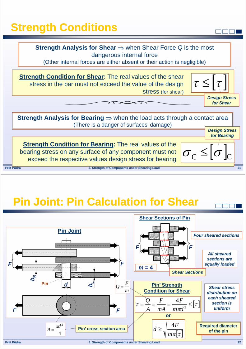
Priit Põdra 3. Strength of Components under Shearing Load 21
Strength ConditionsStrength Conditions
Strength Analysis for Shear when Shear Force Q is the most dangerous internal force
(Other internal forces are either absent or their action is negligible)
Strength Condition for Shear: The real values of the shear stress in the bar must not exceed the value of the design
stress (for shear)
Strength Analysis for Bearing when the load acts through a contact area(There is a danger of surfaces’ damage)
Strength Condition for Bearing: The real values of the bearing stress on any surface of any component must not
exceed the respective values design stress for bearing CC
Design Stress for Shear
Design Stress for Bearing
Priit Põdra
Shear Sections
F F
Shear Sections of Pin
m = 4
3. Strength of Components under Shearing Load 22
Pin Joint: Pin Calculation for ShearPin Joint: Pin Calculation for Shear
FF
d
bR
bL
FF
Pin Joint
Pin Pin’ Strength Condition for Shear
2
4
dm
F
mA
F
A
Q
or
m
Fd
4
Four sheared sections
All sheared sections are
equally loaded
Shear stress distribution on each sheared
section is uniform
Required diameter of the pin
m
FQ
4
2dA
Pin’ cross-section area
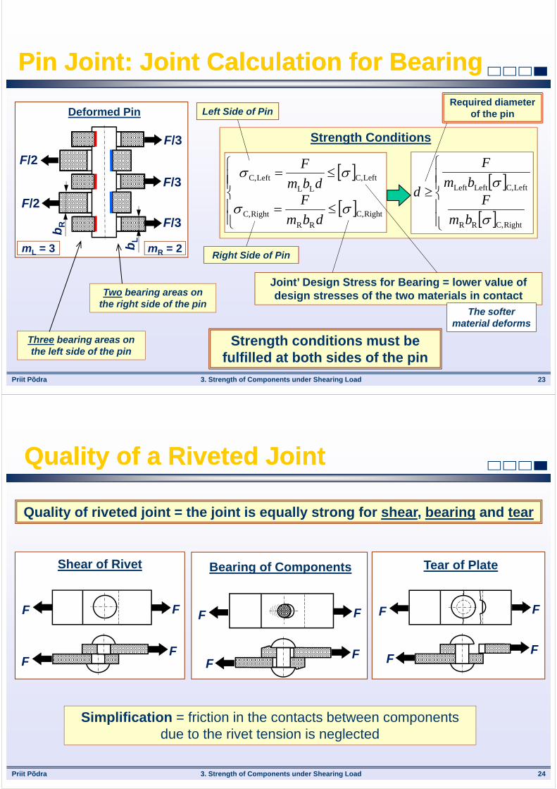
Priit Põdra 3. Strength of Components under Shearing Load 23
Pin Joint: Joint Calculation for BearingPin Joint: Joint Calculation for Bearing
Left Side of Pin
F/2
Deformed Pin
F/2
F/3
F/3
F/3
bR
bL
mR = 2mL = 3
RightC,RR
RightC,
LeftC,LL
LeftC,
dbm
Fdbm
F
RightC,RR
LeftC,LeftLeft
bm
Fbm
F
d
Strength Conditions
Right Side of Pin
Required diameter of the pin
Three bearing areas on the left side of the pin
Two bearing areas on the right side of the pin
Joint’ Design Stress for Bearing = lower value of design stresses of the two materials in contact
The softer material deforms
Strength conditions must be fulfilled at both sides of the pin
Priit Põdra 3. Strength of Components under Shearing Load 24
Quality of a Riveted JointQuality of a Riveted Joint
Quality of riveted joint = the joint is equally strong for shear, bearing and tear
Simplification = friction in the contacts between components due to the rivet tension is neglected
F F
FF
Shear of Rivet
F F
FF
Bearing of Components
F F
FF
Tear of Plate

Priit Põdra 3. Strength of Components under Shearing Load 25
Riveted Joint: Calculation for Shear and BearingRiveted Joint: Calculation for Shear and Bearing
Load is divided equally between all bearing areas (at left and right sides
respectively)
FF
bR
bL
d1
FF
Riveted Joint
Number of shear sections: m = 4Number of bearing areas at the left side of rivet: mL = 3Number of bearing areas at the right side of rivet: mR = 2
Per ONE rivet
Strength Conditions
21
4
dnm
F
nmA
F
RightC,1RR
RightC,
LeftC,1LL
LeftC,
dbnm
Fdbnm
F
RightC,1RR
LeftC,1LL
21
4
dbm
Fdbm
Fdm
F
n
nm
FQ
L/RL/RC, nm
FF
All rivets are equally loaded
Load is divided equally between
all shearing areas
Shear stress distribution is
uniform A
Q
Bearing stress distribution is
uniform C
CC A
F
Rivet Hole Diameter
Priit Põdra 3. Strength of Components under Shearing Load 26
Riveted Joint: Calculation for TearRiveted Joint: Calculation for Tear
Section I Section II
The plate has been weakened by rivet holes
AGross
Section I
Cross-Section Gross Area
ANet
Section II
Cross-Section Net Area
b
d1
The impacy of holes to the plate strength must be checked
Rivet Hole Diameter
11GrossNet bdnAA
Number of Holes in
One (given)
Section
11GrossNet bdnA
N
A
N
N
Adn
b Gross11
1
Strength Conditions

Priit Põdra 3. Strength of Components under Shearing Load 27
Welded Joint: Internal Forces AnalysisWelded Joint: Internal Forces Analysis
Weldments on both sides of the plate
F
z 0B
LW1
LW2 LW2
Q1
Q2h
Weldment are under shearing action
hQFzM
QQFF
20B
21
20
20
h
zFQ 0
1 12
h
zFQ 0
2 2
Shear forces Q and shear
stresses act at the sections of weldments
Load F acts along the axis of L-beams
L-beams are subjected to tension
Equilibrium conditions at the shearing section are used in order to calculate the internal forces
Priit Põdra 3. Strength of Components under Shearing Load 28
Shearing Section of a WeldShearing Section of a Weld
F
Fracture of a Welded Joint Under Shear
Shear Section
WminW,W LhA Nominal Shear Section Area
hW
45
WWminW, 7.045cos hhh
Geometry of Weld = Right Triangle
Outer surface of weld
Minimum Thickness
of Weld
The weld fractures under shear at the section of minimum thickness, this is 45 inclined relative to the fillet weld side

Priit Põdra 3. Strength of Components under Shearing Load 29
Welded Joint: Calculation for ShearWelded Joint: Calculation for Shear
F
Welded Joint Under Shear Action
Q1
WeldsShear Force
Weld Length
WminW,W LhA Nominal Shear Section Area
Weld Nominal Length
WWW 7.0 Lh
Q
A
Q
Shear Stress at the Shear SectionWeld Shear
Force
Strength Condition for Shear
WW7.0 Lh
Q
W1W
1
7.0 Lh
Q
W2W
2
7.0 Lh
Q
WW
11W 7.0
hh
QL
WW
22W 7.0
hh
QL
Weld Lengths
Strength condition must be fulfilled for
each weld separately
Load
Weld’ real length is made a bit longer
Priit Põdra 3. Strength of Components under Shearing Load 30
STRENGTH OF MATERIALSSTRENGTH OF MATERIALS
THANK YOU!THANK YOU!
Questions, please?
Mehhanosüsteemide komponentide õppetool