Stopper cylinders DFST
17
Stopper cylinders DFST
Transcript of Stopper cylinders DFST
Stopper cylinders DFST
Subject to change – 2017/102 � Internet: www.festo.com/catalog/...
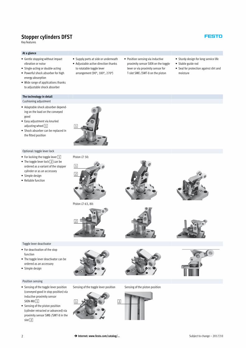
Stopper cylinders DFSTKey features
At a glance
� Gentle stopping without impact
vibration or noise
� Single-acting or double-acting
� Powerful shock absorber for high
energy absorption
� Wide range of applications thanks
to adjustable shock absorber
� Supply ports at side or underneath
� Adjustable active direction thanks
to rotatable toggle lever
arrangement (90°, 180°, 270°)
� Position sensing via inductive
proximity sensor SIEN on the toggle
lever or via proximity sensor for
T-slot SME-/SMT-8 on the piston
� Sturdy design for long service life
� Stable guide rod
� Seal for protection against dirt and
moisture
The technology in detail
Cushioning adjustment
� Adaptable shock absorber depend
ing on the load on the conveyed
good
� Easy adjustment via knurled
adjusting wheel 1
� Shock absorber can be replaced in
the fitted position
1
Optional: toggle lever lock
� For locking the toggle lever 1
� The toggle lever lock 2 can be
ordered as a variant of the stopper
cylinder or as an accessory
� Simple design
� Reliable function
Piston 50:
Piston 63, 80:
1
2
2
Toggle lever deactivator
� For deactivation of the stop
function
� The toggle lever deactivator can be
ordered as an accessory
� Simple design ��
Position sensing
� Sensing of the toggle lever position
(conveyed good in stop position) via
inductive proximity sensor
SIEN-M8 1
� Sensing of the piston position
(cylinder retracted or advanced) via
proximity sensor SME-/SMT-8 in the
slot 2
Sensing of the toggle lever position Sensing of the piston position
1 2
2017/10 – Subject to change 3� Internet: www.festo.com/catalog/...
Stopper cylinders DFSTKey features
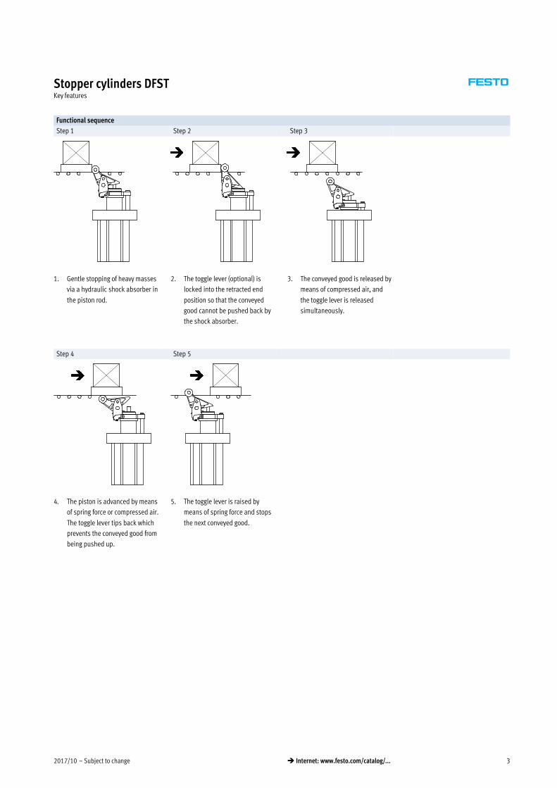
Functional sequence
Step 1 Step 2 Step 3
1. Gentle stopping of heavy masses
via a hydraulic shock absorber in
the piston rod.
2. The toggle lever (optional) is
locked into the retracted end
position so that the conveyed
good cannot be pushed back by
the shock absorber.
3. The conveyed good is released by
means of compressed air, and
the toggle lever is released
simultaneously.
Step 4 Step 5
4. The piston is advanced by means
of spring force or compressed air.
The toggle lever tips back which
prevents the conveyed good from
being pushed up.
5. The toggle lever is raised by
means of spring force and stops
the next conveyed good.
Subject to change – 2017/104 � Internet: www.festo.com/catalog/...
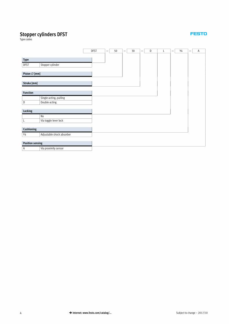
Stopper cylinders DFSTType codes
DFST — 50 — 30 — D L — Y4 — A
Type
DFST Stopper cylinder
Piston � [mm]
Stroke [mm]
Function
Single-acting, pulling
D Double-acting
Locking
No
L Via toggle lever lock
Cushioning
Y4 Adjustable shock absorber
Position sensing
A Via proximity sensor
2017/10 – Subject to change 5� Internet: www.festo.com/catalog/...
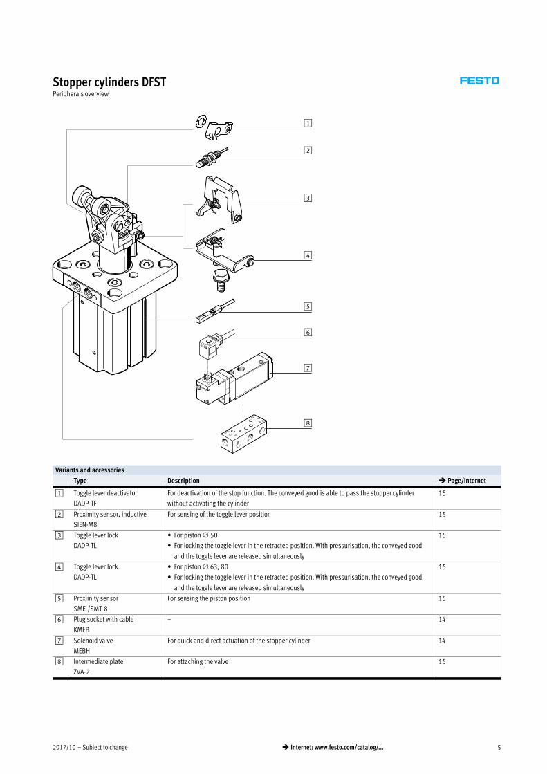
Stopper cylinders DFSTPeripherals overview
1
2
3
4
5
6
7
8
Variants and accessories
Type Description � Page/Internet
1 Toggle lever deactivator
DADP-TF
For deactivation of the stop function. The conveyed good is able to pass the stopper cylinder
without activating the cylinder
15
2 Proximity sensor, inductive
SIEN-M8
For sensing of the toggle lever position 15
3 Toggle lever lock
DADP-TL
� For piston 50
� For locking the toggle lever in the retracted position. With pressurisation, the conveyed good
and the toggle lever are released simultaneously
15
4 Toggle lever lock
DADP-TL
� For piston 63, 80
� For locking the toggle lever in the retracted position. With pressurisation, the conveyed good
and the toggle lever are released simultaneously
15
5 Proximity sensor
SME-/SMT-8
For sensing the piston position 15
6 Plug socket with cable
KMEB
– 14
7 Solenoid valve
MEBH
For quick and direct actuation of the stopper cylinder 14
8 Intermediate plate
ZVA-2
For attaching the valve 15
Subject to change – 2017/106 � Internet: www.festo.com/catalog/...
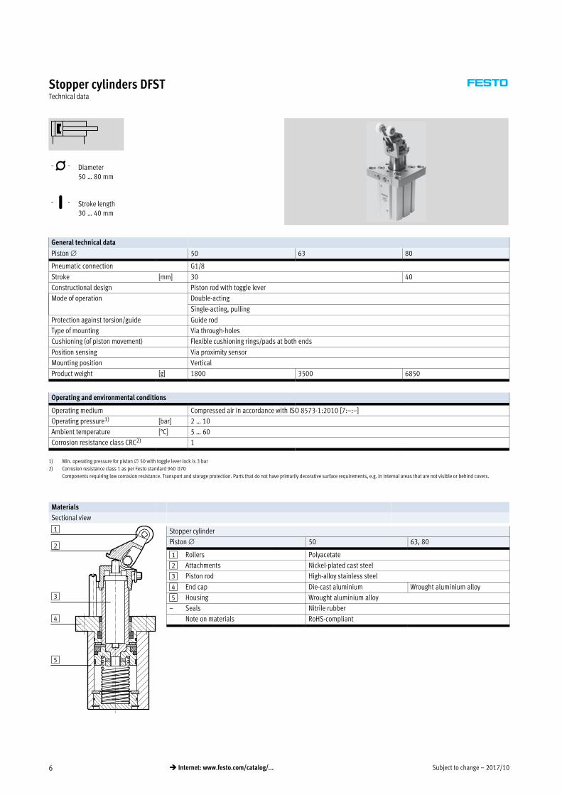
Stopper cylinders DFSTTechnical data
-N- Diameter
50 … 80 mm
-T- Stroke length
30 … 40 mm
General technical data
Piston 50 63 80
Pneumatic connection G1/8
Stroke [mm] 30 40
Constructional design Piston rod with toggle lever
Mode of operation Double-acting
Single-acting, pulling
Protection against torsion/guide Guide rod
Type of mounting Via through-holes
Cushioning (of piston movement) Flexible cushioning rings/pads at both ends
Position sensing Via proximity sensor
Mounting position Vertical
Product weight [g] 1800 3500 6850
Operating and environmental conditions
Operating medium Compressed air in accordance with ISO 85731:2010 [7:–:–]
Operating pressure1) [bar] 2 … 10
Ambient temperature [°C] 5 … 60
Corrosion resistance class CRC2) 1
1) Min. operating pressure for piston 50 with toggle lever lock is 3 bar
2) Corrosion resistance class 1 as per Festo standard 940 070
Components requiring low corrosion resistance. Transport and storage protection. Parts that do not have primarily decorative surface requirements, e.g. in internal areas that are not visible or behind covers.
Materials
Sectional view
Stopper cylinder
Piston 50 63, 80
1 Rollers Polyacetate
2 Attachments Nickel-plated cast steel
3 Piston rod High-alloy stainless steel
4 End cap Die-cast aluminium Wrought aluminium alloy
5 Housing Wrought aluminium alloy
– Seals Nitrile rubber
Note on materials RoHS-compliant4
2
1
3
5
2017/10 – Subject to change 7� Internet: www.festo.com/catalog/...
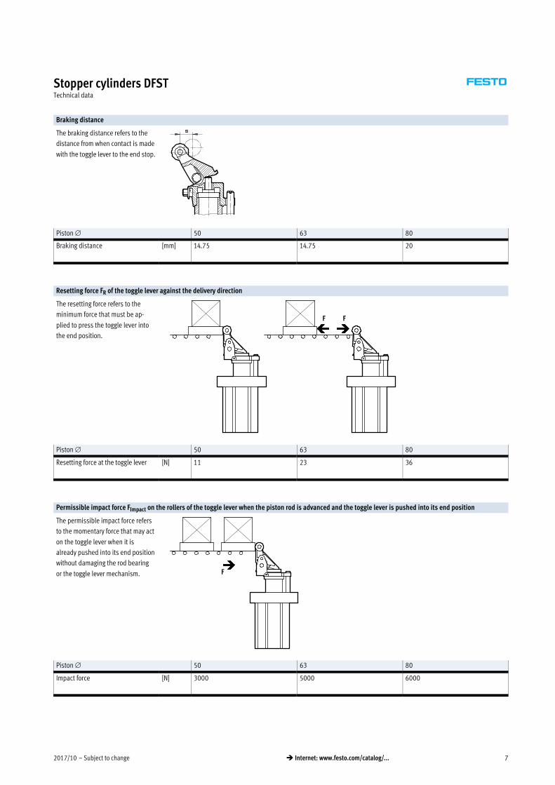
Stopper cylinders DFSTTechnical data
Braking distance
The braking distance refers to the
distance from when contact is made
with the toggle lever to the end stop.
Piston 50 63 80
Braking distance [mm] 14.75 14.75 20
Resetting force FR of the toggle lever against the delivery direction
The resetting force refers to the
minimum force that must be ap
plied to press the toggle lever into
the end position.
F F
Piston 50 63 80
Resetting force at the toggle lever [N] 11 23 36
Permissible impact force FImpact on the rollers of the toggle lever when the piston rod is advanced and the toggle lever is pushed into its end position
The permissible impact force refers
to the momentary force that may act
on the toggle lever when it is
already pushed into its end position
without damaging the rod bearing
or the toggle lever mechanism. F
Piston 50 63 80
Impact force [N] 3000 5000 6000
Subject to change – 2017/108 � Internet: www.festo.com/catalog/...
Stopper cylinders DFSTTechnical data
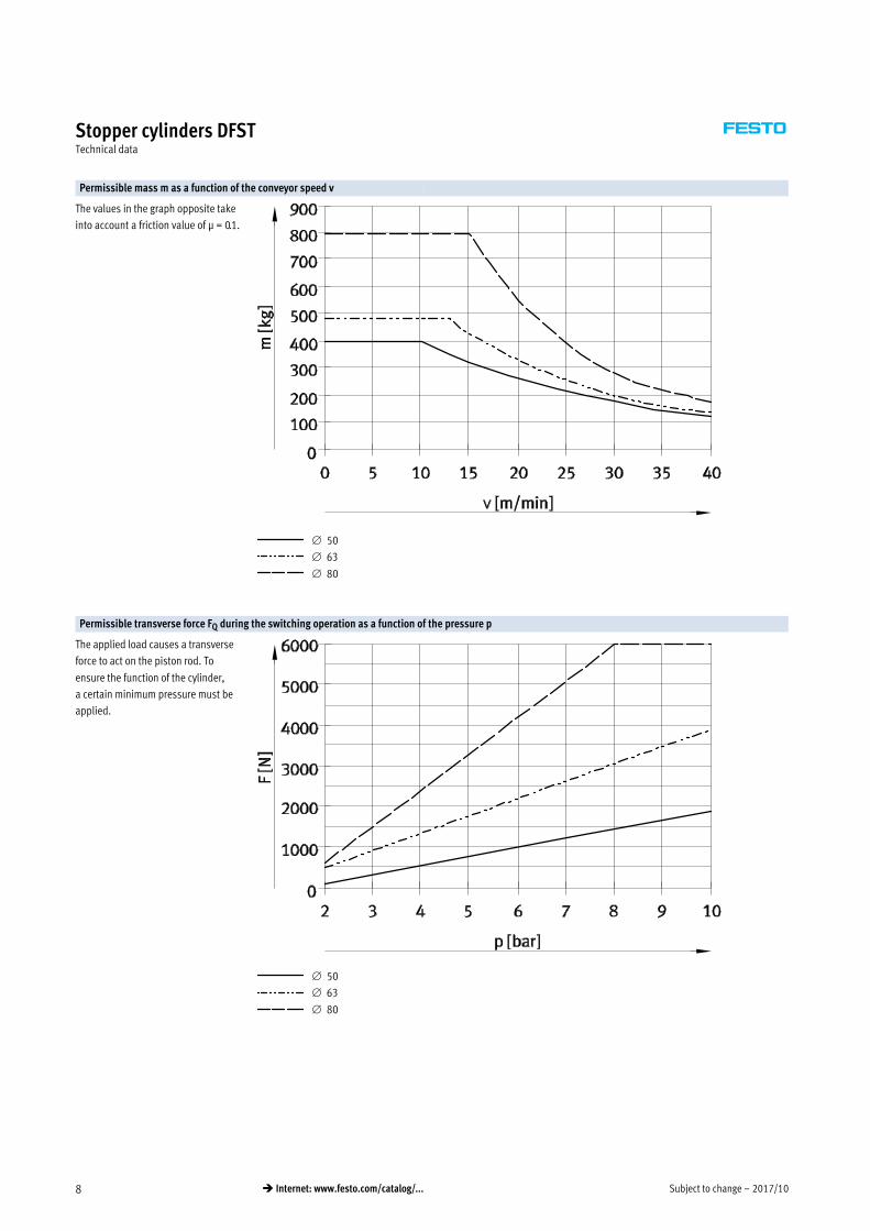
Permissible mass m as a function of the conveyor speed v
The values in the graph opposite take
into account a friction value of μ = 0.1.
50
63
80
Permissible transverse force FQ during the switching operation as a function of the pressure p
The applied load causes a transverse
force to act on the piston rod. To
ensure the function of the cylinder,
a certain minimum pressure must be
applied.
50
63
80
2017/10 – Subject to change 9� Internet: www.festo.com/catalog/...
Stopper cylinders DFSTTechnical data
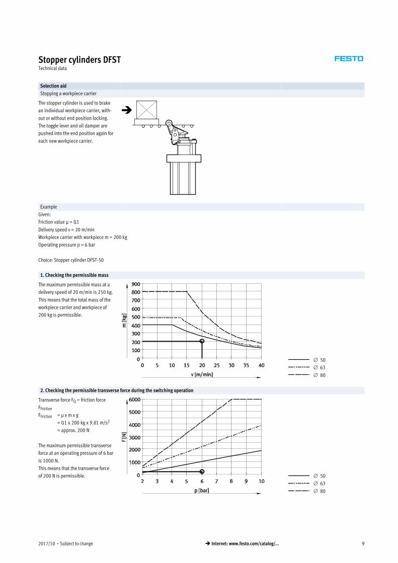
Selection aid
Stopping a workpiece carrier
The stopper cylinder is used to brake
an individual workpiece carrier, with
out or without end position locking.
The toggle lever and oil damper are
pushed into the end position again for
each new workpiece carrier.
Example
Given:
Friction value μ = 0.1
Delivery speed v = 20 m/min
Workpiece carrier with workpiece m = 200 kg
Operating pressure p = 6 bar
Choice: Stopper cylinder DFST-50
1. Checking the permissible mass
The maximum permissible mass at a
delivery speed of 20 m/min is 250 kg.
This means that the total mass of the
workpiece carrier and workpiece of
200 kg is permissible.
50
63
80
2. Checking the permissible transverse force during the switching operation
Transverse force FQ = friction force
FFriction
FFriction = μ x m x g
= 0.1 x 200 kg x 9.81 m/s2
= approx. 200 N
The maximum permissible transverse
force at an operating pressure of 6 bar
is 1000 N.
This means that the transverse force
of 200 N is permissible. 50
63
80
Subject to change – 2017/1010 � Internet: www.festo.com/catalog/...
Stopper cylinders DFSTTechnical data
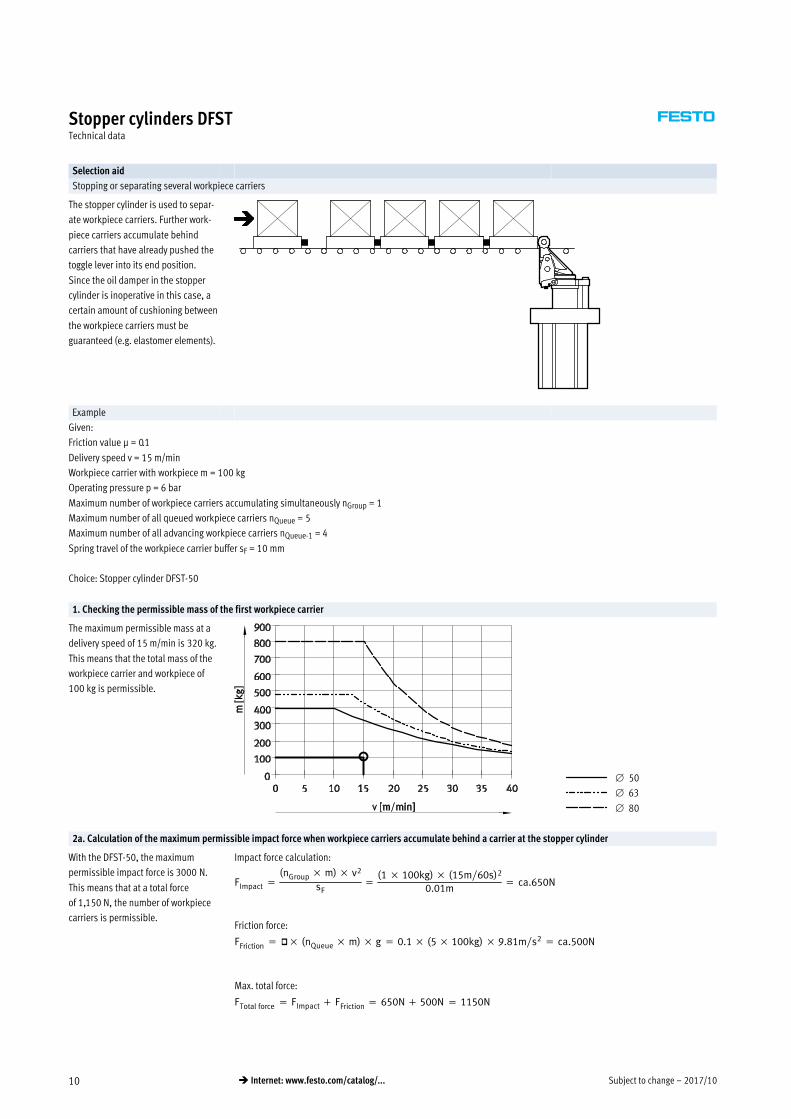
Selection aid
Stopping or separating several workpiece carriers
The stopper cylinder is used to separ
ate workpiece carriers. Further work
piece carriers accumulate behind
carriers that have already pushed the
toggle lever into its end position.
Since the oil damper in the stopper
cylinder is inoperative in this case, a
certain amount of cushioning between
the workpiece carriers must be
guaranteed (e.g. elastomer elements).
Example
Given:
Friction value μ = 0.1
Delivery speed v = 15 m/min
Workpiece carrier with workpiece m = 100 kg
Operating pressure p = 6 bar
Maximum number of workpiece carriers accumulating simultaneously nGroup = 1
Maximum number of all queued workpiece carriers nQueue = 5
Maximum number of all advancing workpiece carriers nQueue-1 = 4
Spring travel of the workpiece carrier buffer sF = 10 mm
Choice: Stopper cylinder DFST-50
1. Checking the permissible mass of the first workpiece carrier
The maximum permissible mass at a
delivery speed of 15 m/min is 320 kg.
This means that the total mass of the
workpiece carrier and workpiece of
100 kg is permissible.
50
63
80
2a. Calculation of the maximum permissible impact force when workpiece carriers accumulate behind a carrier at the stopper cylinder
With the DFST-50, the maximum
permissible impact force is 3000 N.
This means that at a total force
of 1,150 N, the number of workpiece
carriers is permissible.
Impact force calculation:
FImpact �(nGroup � m) � v2
sF�
(1 � 100kg) � (15m�60s)2
0.01m� ca.650N
Friction force:
FFriction � �� (nQueue � m) � g � 0.1 � (5 � 100kg) � 9.81m�s2 � ca.500N
Max. total force:
FTotal force � FImpact � FFriction � 650N � 500N � 1150N
2017/10 – Subject to change 11� Internet: www.festo.com/catalog/...
Stopper cylinders DFSTTechnical data
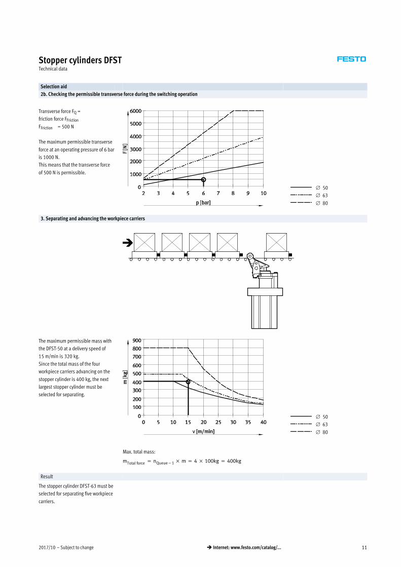
Selection aid
2b. Checking the permissible transverse force during the switching operation
Transverse force FQ =
friction force FFriction
FFriction = 500 N
The maximum permissible transverse
force at an operating pressure of 6 bar
is 1000 N.
This means that the transverse force
of 500 N is permissible.
50
63
80
3. Separating and advancing the workpiece carriers
The maximum permissible mass with
the DFST-50 at a delivery speed of
15 m/min is 320 kg.
Since the total mass of the four
workpiece carriers advancing on the
stopper cylinder is 400 kg, the next
largest stopper cylinder must be
selected for separating.
50
63
80
mTotal force � nQueue�1 � m � 4 � 100kg � 400kg
Max. total mass:
Result
The stopper cylinder DFST-63 must be
selected for separating five workpiece
carriers.
Subject to change – 2017/1012 � Internet: www.festo.com/catalog/...
Stopper cylinders DFSTTechnical data
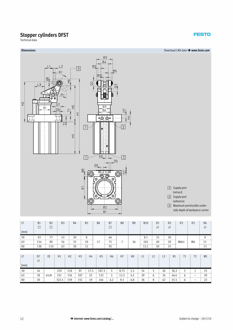
Dimensions Download CAD data � www.festo.com
1 Supply port
(retract)
2 Supply port
(advance)
3 Maximum permissible under
side depth of workpiece carrier
[mm]
B1
™
B2
™
B3 B4 B5 B6 B7
™
B8 B9 B10 D1
D2
D3 D5 D6
50 93 73 43 20 8
17
64
7 36
8.1 32 20
M8x1 M4
9
63 114 90 54 25 10 75 10.1 40 20 11
80 138 110 63 30 12 95 12.1 50 25 13
[mm]
D7
EE H1 H2 H3 H4 H5 H6 H7 H8 L1 L2 L3 R1 T1 T2 W1
50 14
G1/8
219 118 91 17.5 107.5 5 8.75 5.5 14 5 26 36.3 5 1 25
63 18 251 134 107 25 123 5 12.5 4.5 29 6 34 44.4 6 – 20
80 20 322.5 159 151 19 144 4.2 9.5 6.8 36 8 42 55.5 6 – 22
2017/10 – Subject to change 13� Internet: www.festo.com/catalog/...
Stopper cylinders DFSTTechnical data
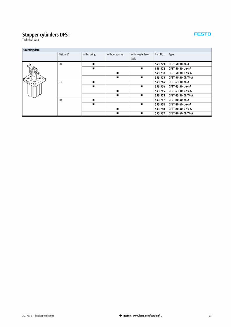
Ordering data
Piston with spring without spring with toggle lever
lock
Part No. Type
50 � 543 729 DFST-50-30-Y4-A
� � 555 572 DFST-50-30-L-Y4-A
� 543 730 DFST-50-30-D-Y4-A
� � 555 573 DFST-50-30-DL-Y4-A
63 � 543 744 DFST-63-30-Y4-A
� � 555 574 DFST-63-30-L-Y4-A
� 543 745 DFST-63-30-D-Y4-A
� � 555 575 DFST-63-30-DL-Y4-A
80 � 543 747 DFST-80-40-Y4-A
� � 555 576 DFST-80-40-L-Y4-A
� 543 748 DFST-80-40-D-Y4-A
� � 555 577 DFST-80-40-DL-Y4-A
Subject to change – 2017/1014 � Internet: www.festo.com/catalog/...
Stopper cylinders DFSTAccessories
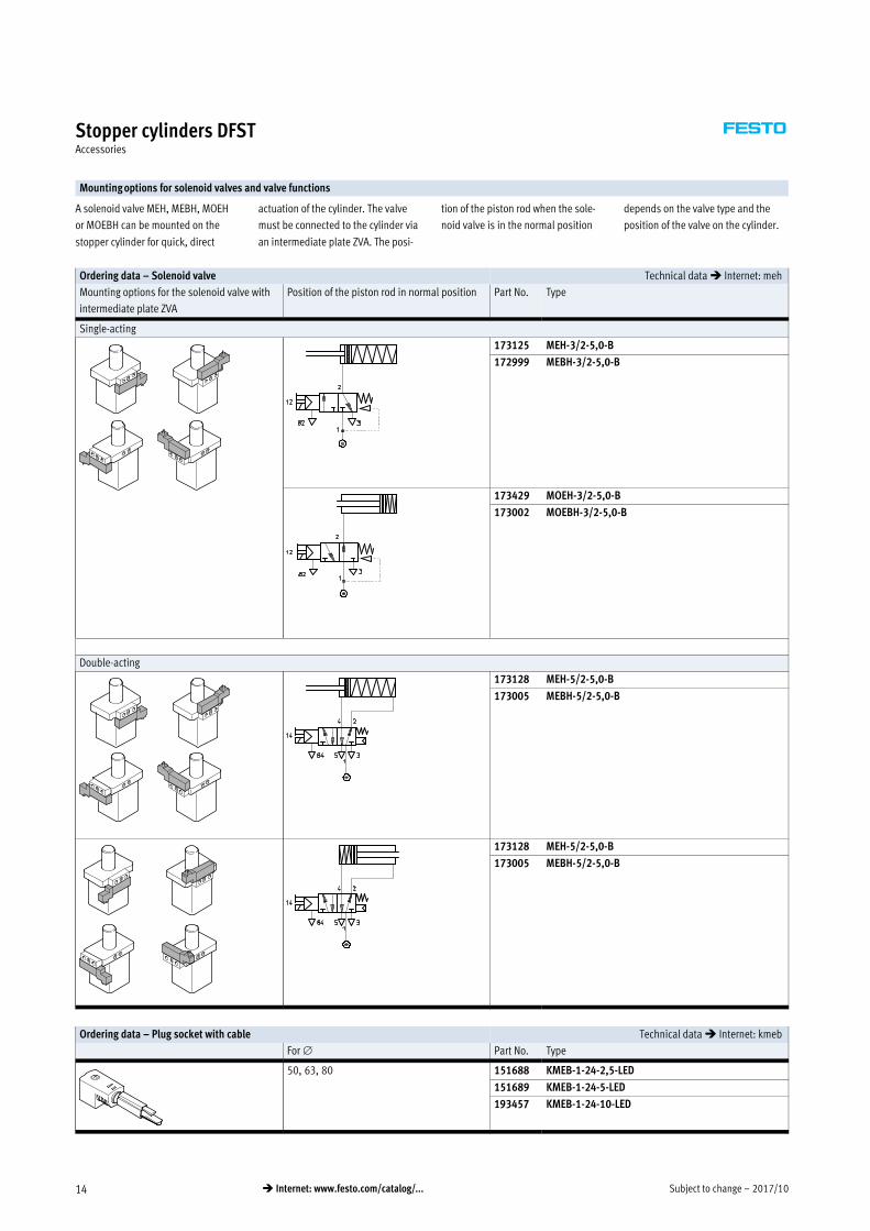
Mounting options for solenoid valves and valve functions
A solenoid valve MEH, MEBH, MOEH
or MOEBH can be mounted on the
stopper cylinder for quick, direct
actuation of the cylinder. The valve
must be connected to the cylinder via
an intermediate plate ZVA. The posi
tion of the piston rod when the sole
noid valve is in the normal position
depends on the valve type and the
position of the valve on the cylinder.
Ordering data – Solenoid valve Technical data � Internet: meh
Mounting options for the solenoid valve with
intermediate plate ZVA
Position of the piston rod in normal position Part No. Type
Single-acting
173125 MEH-3/2-5,0-B
172999 MEBH-3/2-5,0-B
173429 MOEH-3/2-5,0-B
173002 MOEBH-3/2-5,0-B
Double-acting
173128 MEH-5/2-5,0-B
173005 MEBH-5/2-5,0-B
173128 MEH-5/2-5,0-B
173005 MEBH-5/2-5,0-B
Ordering data – Plug socket with cable Technical data � Internet: kmeb
For Part No. Type
50, 63, 80 151688 KMEB-1-24-2,5-LED
151689 KMEB-1-24-5-LED
193457 KMEB-1-24-10-LED
2017/10 – Subject to change 15� Internet: www.festo.com/catalog/...
Stopper cylinders DFSTAccessories
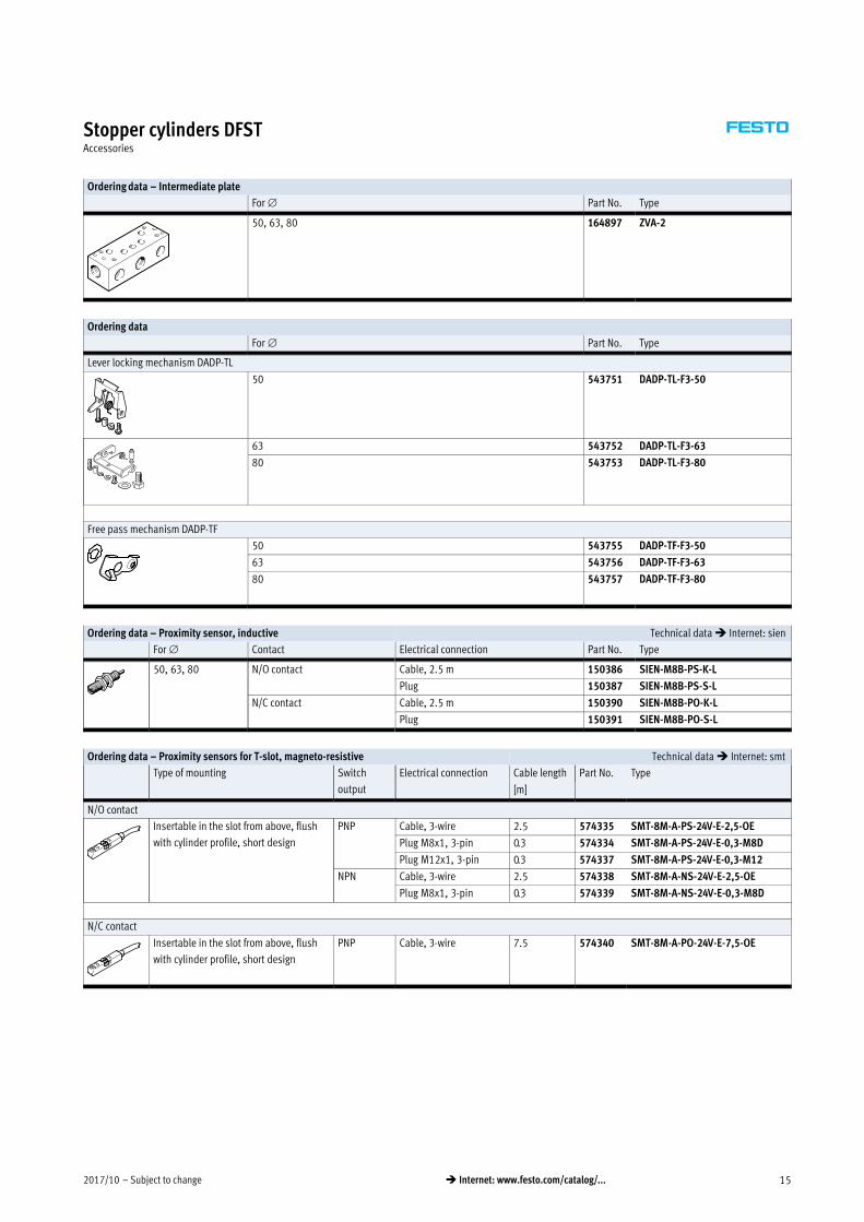
Ordering data – Intermediate plate
For Part No. Type
50, 63, 80 164897 ZVA-2
Ordering data
For Part No. Type
Lever locking mechanism DADP-TL
50 543751 DADP-TL-F3-50
63 543752 DADP-TL-F3-63
80 543753 DADP-TL-F3-80
Free pass mechanism DADP-TF
50 543755 DADP-TF-F3-50
63 543756 DADP-TF-F3-63
80 543757 DADP-TF-F3-80
Ordering data – Proximity sensor, inductive Technical data � Internet: sien
For Contact Electrical connection Part No. Type
50, 63, 80 N/O contact Cable, 2.5 m 150386 SIEN-M8B-PS-K-L
Plug 150387 SIEN-M8B-PS-S-L
N/C contact Cable, 2.5 m 150390 SIEN-M8B-PO-K-L
Plug 150391 SIEN-M8B-PO-S-L
Ordering data – Proximity sensors for T-slot, magneto-resistive Technical data � Internet: smt
Type of mounting Switch
output
Electrical connection Cable length Part No. Type
[m]
N/O contact
Insertable in the slot from above, flush
with cylinder profile, short design
PNP Cable, 3-wire 2.5 574335 SMT-8M-A-PS-24V-E-2,5-OE
Plug M8x1, 3-pin 0.3 574334 SMT-8M-A-PS-24V-E-0,3-M8D
Plug M12x1, 3-pin 0.3 574337 SMT-8M-A-PS-24V-E-0,3-M12
NPN Cable, 3-wire 2.5 574338 SMT-8M-A-NS-24V-E-2,5-OE
Plug M8x1, 3-pin 0.3 574339 SMT-8M-A-NS-24V-E-0,3-M8D
N/C contact
Insertable in the slot from above, flush
with cylinder profile, short design
PNP Cable, 3-wire 7.5 574340 SMT-8M-A-PO-24V-E-7,5-OE
Subject to change – 2017/1016 � Internet: www.festo.com/catalog/...
Stopper cylinders DFSTAccessories
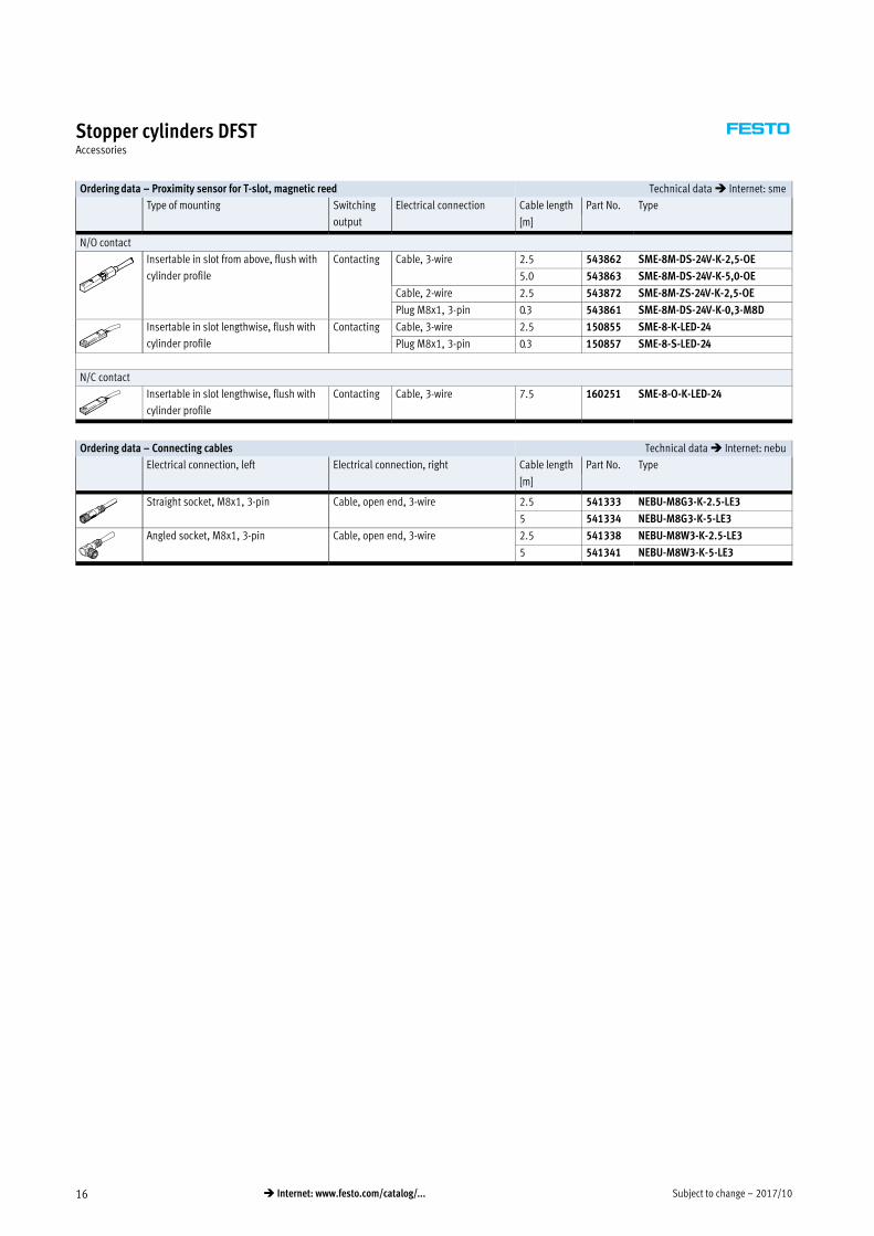
Ordering data – Proximity sensor for T-slot, magnetic reed Technical data � Internet: sme
Type of mounting Switching
output
Electrical connection Cable length Part No. Type
[m]
N/O contact
Insertable in slot from above, flush with
cylinder profile
Contacting Cable, 3-wire 2.5 543862 SME-8M-DS-24V-K-2,5-OE
5.0 543863 SME-8M-DS-24V-K-5,0-OE
Cable, 2-wire 2.5 543872 SME-8M-ZS-24V-K-2,5-OE
Plug M8x1, 3-pin 0.3 543861 SME-8M-DS-24V-K-0,3-M8D
Insertable in slot lengthwise, flush with
cylinder profile
Contacting Cable, 3-wire 2.5 150855 SME-8-K-LED-24
Plug M8x1, 3-pin 0.3 150857 SME-8-S-LED-24
N/C contact
Insertable in slot lengthwise, flush with
cylinder profile
Contacting Cable, 3-wire 7.5 160251 SME-8-O-K-LED-24
Ordering data – Connecting cables Technical data � Internet: nebu
Electrical connection, left Electrical connection, right Cable length Part No. Type
[m]
Straight socket, M8x1, 3-pin Cable, open end, 3-wire 2.5 541333 NEBU-M8G3-K-2.5-LE3
5 541334 NEBU-M8G3-K-5-LE3
Angled socket, M8x1, 3-pin Cable, open end, 3-wire 2.5 541338 NEBU-M8W3-K-2.5-LE3
5 541341 NEBU-M8W3-K-5-LE3
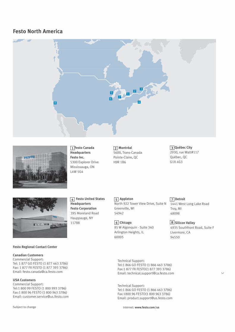
Festo North America
Festo Regional Contact Center
Canadian CustomersCommercial Support:Tel: 1 O FESTO 1 3 3Fax: 1 F FESTO 1 393 3Email: festo canada ca festo com
USA CustomersCommercial Support:Tel:1 00 99 FESTO 1 00 993 3Fax:1 00 9 FESTO 1 00 9 3 3Email: customer service us festo com
Technical Support:Tel:1 O FESTO 1 3 3Fax:1 F FESTO 1 393 3Email: technical support ca festo com
Technical Support:Tel:1 O FESTO 1 3 3Fax:1 00 9 FESTO 1 00 9 3 3Email: product support us festo com
C
Festo Canada HeadquartersFesto Inc.5300 Explorer Drive
ississauga, OL W 5
Montréal5600, Trans-CanadaPointe-Claire, QC
9 1 6
Québec City930, rue Watt 11
Québec, QC1 3
Festo United StatesHeadquarters Festo Corporation395 Moreland Road
auppauge, 11
etroit1 1 West Long Lake RoadTroy, MI
09
Silicon Valley935 Southfront Road, Suite F
Livermore, CA9 550
Appletonorth 9 Tower iew Drive, Suite
Greenville, WI5 9
Chicago5 W Algonquin - Suite 3 0
Arlington eights, IL60005
6
1 2 3
4 5 7
8
Sub ect to change Internet: www.festo.com/us