Exit Stopper
8
- 1 - Exit Stopper ® STI-6400 Series Features · Helps prevent unauthorized exits/entries through doors. · Easy to install. Warning sound when turning on (two flashes/beeps) and off (one flash/beep). · Add warning in second language with provided labels (21 languages). · Select volume, alarm duration and delay settings. · Mount on top, right, left or next to almost any door. · Select on-site whether to use an alarm or annunciator. · Low battery detection, beep and flashes. · Alarm sounds and high power LED light flashes when activated. · Dry contact Form C relay. · Protect anything such as cabinet, extinguisher, etc. with an external reed or any mechanical switch. Rely on STI ®
Transcript of Exit Stopper

- 1 -
Exit Stopper®
STI-6400 Series
Features
· Helps prevent unauthorized exits/entries through doors.· Easy to install. Warning sound when turning on (two flashes/beeps) and off
(one flash/beep).· Add warning in second language with provided labels (21 languages).· Select volume, alarm duration and delay settings.· Mount on top, right, left or next to almost any door.· Select on-site whether to use an alarm or annunciator.· Low battery detection, beep and flashes.· Alarm sounds and high power LED light flashes when activated.· Dry contact Form C relay.· Protect anything such as cabinet, extinguisher, etc. with an external reed or
any mechanical switch.
Rely on STI®
- 2 -
WarningsAll units are recommended for indoor use only. Unit must be tested periodically to verify the life of battery. STI recommends you change the 9 Volt battery twice a year. To hear alarm when normal work environment is loud, may need to purchase remote horns. When purchasing a remote unit (STI-6403 or STI-6404) you will need to periodically test the connections to make sure audibles function at a sound level to alert staff. Maximum of three remote alarms may be used in parallel.
All specifications and information shown are current as of publication and subject to change without notice.
WARNING: This product can expose you to chemicals including Bisphenol A, which is known to the State of California to cause reproductive harm and Dichloromethane, which is known to the State of California to cause cancer. For more information go to www.P65Warnings.ca.gov.
Warranty Information· Three year guarantee against breakage of polycarbonate in normal use (one year on electro
mechanical and electronic components).· Electronic warranty form at www.sti-usa.com/wc14
- 3 -
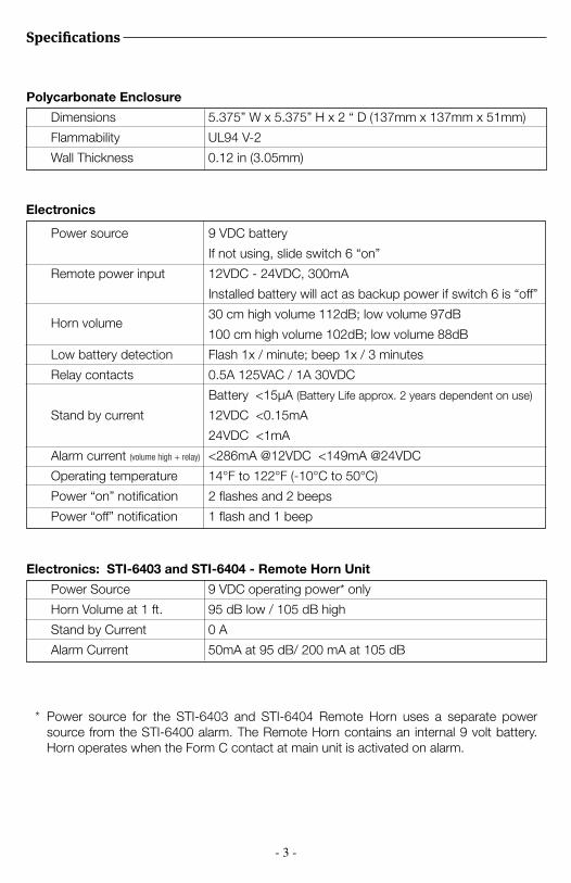
Specifications
Polycarbonate Enclosure
Dimensions 5.375” W x 5.375” H x 2 “ D (137mm x 137mm x 51mm)
Flammability UL94 V-2
Wall Thickness 0.12 in (3.05mm)
Electronics: STI-6403 and STI-6404 - Remote Horn Unit
Power Source 9 VDC operating power* only
Horn Volume at 1 ft. 95 dB low / 105 dB high
Stand by Current 0 A
Alarm Current 50mA at 95 dB/ 200 mA at 105 dB
* Power source for the STI-6403 and STI-6404 Remote Horn uses a separate power source from the STI-6400 alarm. The Remote Horn contains an internal 9 volt battery. Horn operates when the Form C contact at main unit is activated on alarm.
9 VDC battery
If not using, slide switch 6 “on”
12VDC - 24VDC, 300mA
Installed battery will act as backup power if switch 6 is “off”
30 cm high volume 112dB; low volume 97dB
100 cm high volume 102dB; low volume 88dB
Flash 1x / minute; beep 1x / 3 minutes
0.5A 125VAC / 1A 30VDC
Battery <15μA (Battery Life approx. 2 years dependent on use)
12VDC <0.15mA
24VDC <1mA
<286mA @12VDC <149mA @24VDC
14°F to 122°F (-10°C to 50°C)
2 flashes and 2 beeps
1 flash and 1 beep
Power source
Remote power input
Low battery detection
Relay contacts
Stand by current
Alarm current (volume high + relay)
Operating temperature
Power “on” notification
Power “off” notification
Horn volume
Electronics
- 4 -
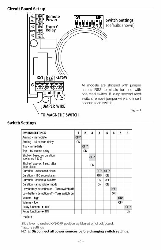
Circuit Board Set-up
Switch Settings
Remote Power
Form CRelay
RS2RS1
JUMPER WIRE
Switch Settings(defaults shown)
KEYSW
TO MAGNETIC SWITCH
All models are shipped with jumper across RS2 terminals for use with one reed switch. If using second reed switch, remove jumper wire and insert second reed switch.
Figure 1
Slide lever to desired ON/OFF position as labeled on circuit board.*factory settingsNOTE: Disconnect all power sources before changing switch settings.
SWITCH SETTINGS 1 2 3 4 5 6 7 8Arming - immediate OFF*Arming - 15 second delay ONTrip - immediate OFF*Trip - 15 second delay ONShut-off based on duration
Shut-off approx. 3 sec. after
Duration - 30 second alarm OFF* OFF*Duration - 180 second alarm OFF ONDuration - continuous alarm ON OFFDuration - annunciator mode ON ONLow battery detection on - Turn switch off OFF*Low battery detection off - Turn switch on ONVolume - high ON*Volume - low OFFRelay function OFF OFF*Relay function ON ON
OFF*
ONdoor closes
(switches 4 & 5)
*default
- 5 -
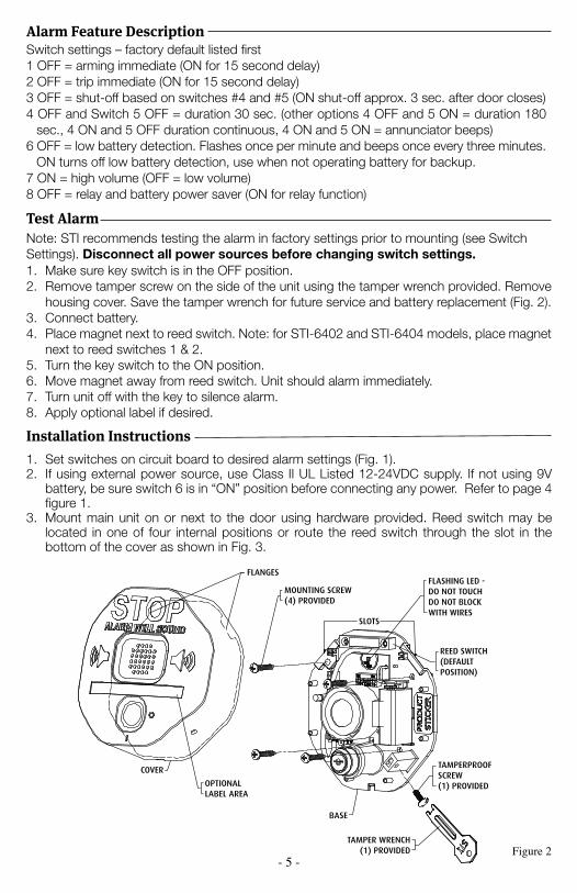
Alarm Feature DescriptionSwitch settings – factory default listed first1 OFF = arming immediate (ON for 15 second delay)2 OFF = trip immediate (ON for 15 second delay)3 OFF = shut-off based on switches #4 and #5 (ON shut-off approx. 3 sec. after door closes)4 OFF and Switch 5 OFF = duration 30 sec. (other options 4 OFF and 5 ON = duration 180
sec., 4 ON and 5 OFF duration continuous, 4 ON and 5 ON = annunciator beeps)6 OFF = low battery detection. Flashes once per minute and beeps once every three minutes. ON turns off low battery detection, use when not operating battery for backup.7 ON = high volume (OFF = low volume)8 OFF = relay and battery power saver (ON for relay function)
Installation Instructions1. Set switches on circuit board to desired alarm settings (Fig. 1).2. If using external power source, use Class II UL Listed 12-24VDC supply. If not using 9V
battery, be sure switch 6 is in “ON” position before connecting any power. Refer to page 4 figure 1.
3. Mount main unit on or next to the door using hardware provided. Reed switch may be located in one of four internal positions or route the reed switch through the slot in the bottom of the cover as shown in Fig. 3.
Figure 2
Test AlarmNote: STI recommends testing the alarm in factory settings prior to mounting (see Switch Settings). Disconnect all power sources before changing switch settings.1. Make sure key switch is in the OFF position.2. Remove tamper screw on the side of the unit using the tamper wrench provided. Remove
housing cover. Save the tamper wrench for future service and battery replacement (Fig. 2).3. Connect battery.4. Place magnet next to reed switch. Note: for STI-6402 and STI-6404 models, place magnet
next to reed switches 1 & 2. 5. Turn the key switch to the ON position.6. Move magnet away from reed switch. Unit should alarm immediately.7. Turn unit off with the key to silence alarm.8. Apply optional label if desired.
COVER
FLANGES
MOUNTING SCREW(4) PROVIDED
SLOTS
FLASHING LED - DO NOT TOUCHDO NOT BLOCK WITH WIRES
REED SWITCH(DEFAULT POSITION)
BASE
TAMPERPROOF SCREW(1) PROVIDED
TAMPER WRENCH(1) PROVIDED
REMOVE FRONT COVER AND ROUTE REED SWITCH WIRES THROUGH NOTCH ON BOTTOM SURFACE AS SHOWN
SPACERS (USE AS NECESSARY)NOTE: 2 SPACERS UNDER BOTH
MAGNET AND REED SWITCH MUST BE USED ON STEEL DOORS
MAGNET
SCREW(2) PROVIDED
MAXIMUM GAP3/4 in. (19mm)
ANCHOR(2) PROVIDED
KIT-E06402REED SWITCH(RS2)OPTIONAL:
TO REMOTE HORNSTI-6403
TERMINAL BLOCK
INTERNALREED SWITCH (RS1)
COMNO
OPTIONALLABEL AREA
- 6 -
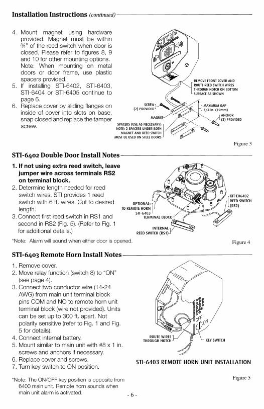
STI-6402 Double Door Install Notes1. If not using extra reed switch, leave
jumper wire across terminals RS2 on terminal block.
2. Determine length needed for reed switch wires. STI provides 1 reed switch with 6 ft. wires. Cut to desired length.
3. Connect first reed switch in RS1 and second in RS2 (Fig. 5). (Refer to Fig. 1 for additional details.)
STI-6403 Remote Horn Install Notes
NOTE: WIRING NOT PROVIDED
NOTE: 14-24 AWG MAY BE USED.
B
EXISTING
EXISTING
TO STI 6400 CIRCUITBOARD TERMINAL STRIP.
VIEW IN DIRECTION OF ARROW
REMOTE HORN WIRE CONNECTIONS
STI-6403 REMOTE HORN UNIT INSTALLATION
B
ROUTE WIRESTHROUGH NOTCH KEY SWITCH
1. Remove cover.2. Move relay function (switch 8) to “ON”
(see page 4).3. Connect two conductor wire (14-24
AWG) from main unit terminal block pins COM and NO to remote horn unit terminal block (wire not provided). Units can be set up to 300 ft. apart. Not polarity sensitive (refer to Fig. 1 and Fig. 5 for details).
4. Connect internal battery.5. Mount similar to main unit with #8 x 1 in.
screws and anchors if necessary.6. Replace cover and screws.7. Turn key switch to ON position.
*Note: The ON/OFF key position is opposite from 6400 main unit. Remote horn sounds when main unit alarm is activated.
Figure 4
Figure 5
COVER
FLANGESMOUNTING SCREW(4) PROVIDED
SLOTS
FLASHING LED - DO NOT TOUCHDO NOT BLOCK WITH WIRES
REED SWITCH(DEFAULT POSITION)
BASE
TAMPERPROOF SCREW(1) PROVIDED
TAMPER WRENCH(1) PROVIDED
REMOVE FRONT COVER AND ROUTE REED SWITCH WIRES THROUGH NOTCH ON BOTTOM SURFACE AS SHOWN
SPACERS (USE AS NECESSARY)NOTE: 2 SPACERS UNDER BOTH
MAGNET AND REED SWITCH MUST BE USED ON STEEL DOORS
MAGNET
SCREW(2) PROVIDED
MAXIMUM GAP3/4 in. (19mm)
ANCHOR(2) PROVIDED
KIT-E06402REED SWITCH(RS2)OPTIONAL:
TO REMOTE HORNSTI-6403
TERMINAL BLOCK
INTERNALREED SWITCH (RS1)
COMNO
OPTIONALLABEL AREA
*Note: Alarm will sound when either door is opened.
Figure 3
COVER
FLANGESMOUNTING SCREW(4) PROVIDED
SLOTS
FLASHING LED - DO NOT TOUCHDO NOT BLOCK WITH WIRES
REED SWITCH(DEFAULT POSITION)
BASE
TAMPERPROOF SCREW(1) PROVIDED
TAMPER WRENCH(1) PROVIDED
REMOVE FRONT COVER AND ROUTE REED SWITCH WIRES THROUGH NOTCH ON BOTTOM SURFACE AS SHOWN
SPACERS (USE AS NECESSARY)NOTE: 2 SPACERS UNDER BOTH
MAGNET AND REED SWITCH MUST BE USED ON STEEL DOORS
MAGNET
SCREW(2) PROVIDED
MAXIMUM GAP3/4 in. (19mm)
ANCHOR(2) PROVIDED
KIT-E06402REED SWITCH(RS2)OPTIONAL:
TO REMOTE HORNSTI-6403
TERMINAL BLOCK
INTERNALREED SWITCH (RS1)
COMNO
OPTIONALLABEL AREA
4. Mount magnet using hardware provided. Magnet must be within ¾” of the reed switch when door is closed. Please refer to figures 8, 9 and 10 for other mounting options.
Note: When mounting on metal doors or door frame, use plastic spacers provided.
5. If installing STI-6402, STI-6403, STI-6404 or STI-6405 continue to page 6.
6. Replace cover by sliding flanges on inside of cover into slots on base, snap closed and replace the tamper screw.
Installation Instructions (continued)
- 7 -
Mounting Options
Figure 8
POLYCARBONATE COVER
POLYCARBONATE BASE
120 dB HORN
ALARM DURATION
ALARM TRIP DELAY
EXIT DELAYVOLUME
VIEW OF THE CIRCUIT BOARD
SCREW6 x 1 1/4 in.
(2) PROVIDED
ANCHOR(2) PROVIDED
BOTTOM SURFACE AS SHOWNWIRES THROUGH NOTCH ONAND ROUTE REED SWITCHREMOVE FRONT COVER
VIEW SHOWING MAGNET INSTALLATION
MAGNET
NC COM NO GD V+ RS1 RS2 KEYSW
TERMINAL BLOCK WIRING CONNECTIONS
FORM
CD
RYCO
NTA
CTS
REM
OTE
PO
WER
INPU
T9-
24 V
DC
REED
SWIT
CHTE
RMIN
ALS
KEY
SWIT
CHTE
RMIN
ALS
INTERNAL REED SWITCH(RS1)
ALARM DURATION
ALARM TRIP DELAY
EXIT DELAYVOLUME
VIEW OF THE CIRCUIT BOARD
MAXIMUM GAP 3/4 in. (19mm) 3/8 in. (9.5mm) ON METAL DOORAND FRAME
SPACERS (USE AS NECESSARY)NOTE: 2 SPACERS UNDER BOTHMAGNET AND REED SWITCHMUST BE USED ON STEEL DOORS
4
3
2
1
NCCOMNOGDV+RS1RS2KEYSW
SLOTSFLANGES
TERMINAL STRIP
9 VOLT BATTERY
19011 TAMPERPROOF SCREW(1) PROVIDED
19016 TAMPER WRENCH(1) PROVIDED
BASE
19014 MOUNTING SCREW(4) PROVIDED
REED SWITCHMOUNTING LOCATIONS
(LABELED 1-4)
COVER
NCCOMNOGDV+RS1RS2KEYSW
4
3
2
1
NCCOMNOGDV+RS1RS2KEYSW
SLOTSFLANGES
TERMINAL STRIP
9 VOLT BATTERY
19011 TAMPERPROOF SCREW(1) PROVIDED
19016 TAMPER WRENCH(1) PROVIDEDBASE
19014 MOUNTING SCREW(4) PROVIDED
REED SWITCHMOUNTING LOCATIONS
(LABELED 1-4)
COVER
4
3
2
1
ALARM SOUNDS WHEN DOOR IS OPENED
EMERGENCY USE ONLY
ON OFF
NCCOMNOGDV+RS1RS2KEYSW
SLOTS
FLANGES
TERMINAL STRIP9 VOLT BATTERY
TAMPERPROOF SCREW(1) PROVIDED
TAMPER WRENCH(1) PROVIDEDBASE
MOUNTING SCREW(4) PROVIDED
REED SWITCHMOUNTING LOCATIONS
(LABELED 1-4)
COVER
TO KEYSWITCH
KIT-E06402 REED SWITCH(RS2)
OPTIONAL:TO REMOTE
HORNSTI-6403
TERMINAL BLOCK
VIEW SHOWING INSTALLATION OFADDTIONAL REED SWITCH KIT-E06402
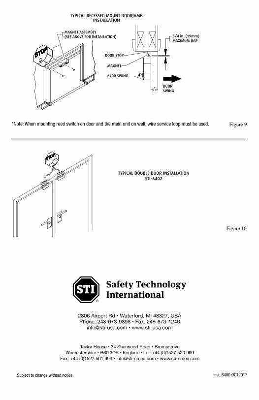
3/4 in. (19mm)MAXIMUM GAP
MAGNET ASSEMBLY(SEE ABOVE FOR INSTALLATION)
DOORSWING
6400 SWING
MAGNET
DOOR STOP
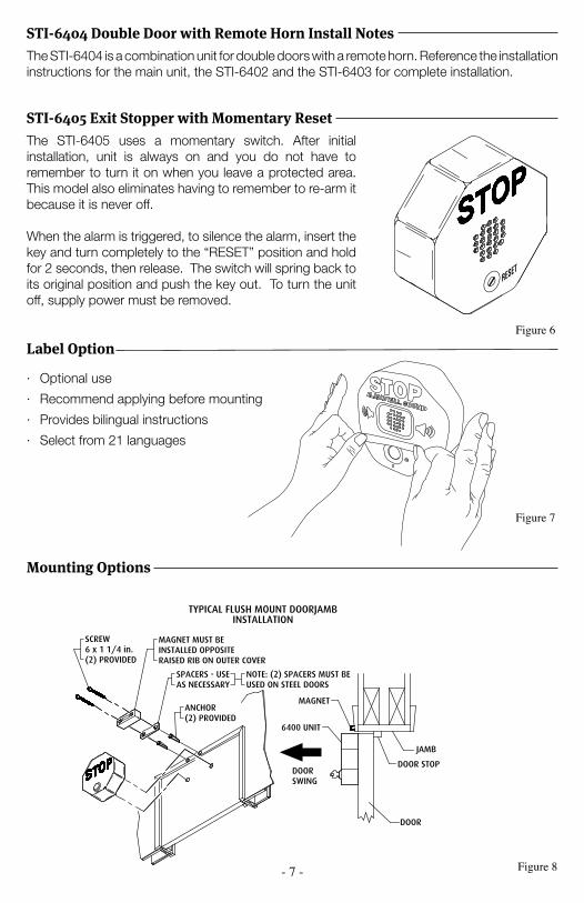
MAGNET MUST BEINSTALLED OPPOSITERAISED RIB ON OUTER COVER
SCREW6 x 1 1/4 in.(2) PROVIDED
SPACERS - USEAS NECESSARY
NOTE: (2) SPACERS MUST BEUSED ON STEEL DOORS
ANCHOR(2) PROVIDED
MAGNET
6400 UNIT
DOORSWING
JAMB
DOOR STOP
DOOR
TYPICAL FLUSH MOUNT DOORJAMBINSTALLATION
TYPICAL RECESSED MOUNT DOORJAMBINSTALLATION
JUMPER WIRE
Label Option
Figure 7
· Optional use
· Recommend applying before mounting
· Provides bilingual instructions
· Select from 21 languages
STI-6404 Double Door with Remote Horn Install NotesThe STI-6404 is a combination unit for double doors with a remote horn. Reference the installation instructions for the main unit, the STI-6402 and the STI-6403 for complete installation.
STI-6405 Exit Stopper with Momentary ResetThe STI-6405 uses a momentary switch. After initial installation, unit is always on and you do not have to remember to turn it on when you leave a protected area. This model also eliminates having to remember to re-arm it because it is never off.
When the alarm is triggered, to silence the alarm, insert the key and turn completely to the “RESET” position and hold for 2 seconds, then release. The switch will spring back to its original position and push the key out. To turn the unit off, supply power must be removed.
RESET
Figure 6
- 8 -
Inst. 6400 OCT2017Subject to change without notice.
2306 Airport Rd • Waterford, MI 48327, USAPhone: 248-673-9898 • Fax: 248-673-1246
[email protected] • www.sti-usa.com
Taylor House • 34 Sherwood Road • BromsgroveWorcestershire • B60 3DR • England • Tel: +44 (0)1527 520 999
Fax: +44 (0)1527 501 999 • [email protected] • www.sti-emea.com
TYPICAL DOUBLE DOOR INSTALLATION
STI 6402
TYPICAL DOUBLE DOOR INSTALLATIONSTI-6402
Figure 10
*Note: When mounting reed switch on door and the main unit on wall, wire service loop must be used. Figure 9
POLYCARBONATE COVER
POLYCARBONATE BASE
120 dB HORN
ALARM DURATION
ALARM TRIP DELAY
EXIT DELAYVOLUME
VIEW OF THE CIRCUIT BOARD
SCREW6 x 1 1/4 in.
(2) PROVIDED
ANCHOR(2) PROVIDED
BOTTOM SURFACE AS SHOWNWIRES THROUGH NOTCH ONAND ROUTE REED SWITCHREMOVE FRONT COVER
VIEW SHOWING MAGNET INSTALLATION
MAGNET
NC COM NO GD V+ RS1 RS2 KEYSW
TERMINAL BLOCK WIRING CONNECTIONS
FORM
CD
RYCO
NTA
CTS
REM
OTE
PO
WER
INPU
T9-
24 V
DC
REE
DSW
ITCH
TER
MIN
ALS
KEY
SWIT
CHTE
RM
INA
LS
INTERNAL REED SWITCH(RS1)
ALARM DURATION
ALARM TRIP DELAY
EXIT DELAYVOLUME
VIEW OF THE CIRCUIT BOARD
MAXIMUM GAP 3/4 in. (19mm) 3/8 in. (9.5mm) ON METAL DOORAND FRAME
SPACERS (USE AS NECESSARY)NOTE: 2 SPACERS UNDER BOTHMAGNET AND REED SWITCHMUST BE USED ON STEEL DOORS
4
3
2
1
NCCOMNOGDV+RS1RS2KEYSW
SLOTSFLANGES
TERMINAL STRIP
9 VOLT BATTERY
19011 TAMPERPROOF SCREW(1) PROVIDED
19016 TAMPER WRENCH(1) PROVIDED
BASE
19014 MOUNTING SCREW(4) PROVIDED
REED SWITCHMOUNTING LOCATIONS
(LABELED 1-4)
COVER
NCCOMNOGDV+RS1RS2KEYSW
4
3
2
1
NCCOMNOGDV+RS1RS2KEYSW
SLOTSFLANGES
TERMINAL STRIP
9 VOLT BATTERY
19011 TAMPERPROOF SCREW(1) PROVIDED
19016 TAMPER WRENCH(1) PROVIDEDBASE
19014 MOUNTING SCREW(4) PROVIDED
REED SWITCHMOUNTING LOCATIONS
(LABELED 1-4)
COVER
4
3
2
1
ALARM SOUNDS WHEN DOOR IS OPENED
EMERGENCY USE ONLY
ON OFF
NCCOMNOGDV+RS1RS2KEYSW
SLOTS
FLANGES
TERMINAL STRIP9 VOLT BATTERY
TAMPERPROOF SCREW(1) PROVIDED
TAMPER WRENCH(1) PROVIDEDBASE
MOUNTING SCREW(4) PROVIDED
REED SWITCHMOUNTING LOCATIONS
(LABELED 1-4)
COVER
TO KEYSWITCH
KIT-E06402 REED SWITCH(RS2)
OPTIONAL:TO REMOTE
HORNSTI-6403
TERMINAL BLOCK
VIEW SHOWING INSTALLATION OFADDTIONAL REED SWITCH KIT-E06402
3/4 in. (19mm)MAXIMUM GAP
MAGNET ASSEMBLY(SEE ABOVE FOR INSTALLATION)
DOORSWING
6400 SWING
MAGNET
DOOR STOP
MAGNET MUST BEINSTALLED OPPOSITERAISED RIB ON OUTER COVER
SCREW6 x 1 1/4 in.(2) PROVIDED
SPACERS - USEAS NECESSARY
NOTE: (2) SPACERS MUST BEUSED ON STEEL DOORS
ANCHOR(2) PROVIDED
MAGNET
6400 UNIT
DOORSWING
JAMB
DOOR STOP
DOOR
TYPICAL FLUSH MOUNT DOORJAMBINSTALLATION
TYPICAL RECESSED MOUNT DOORJAMBINSTALLATION
JUMPER WIRE