Stepper Motors - cnckaran · PTM-24M PTM-24T PTM-24B PFL35T 42 PF(C)42 PFC42H PF(C)42T PTM24H...
32
Stepper Motors Nippon Pulse WWW.NPMEUROPE.COM WWW.NPMEUROPE.COM NPM Your Partner in Motion Control
Transcript of Stepper Motors - cnckaran · PTM-24M PTM-24T PTM-24B PFL35T 42 PF(C)42 PFC42H PF(C)42T PTM24H...
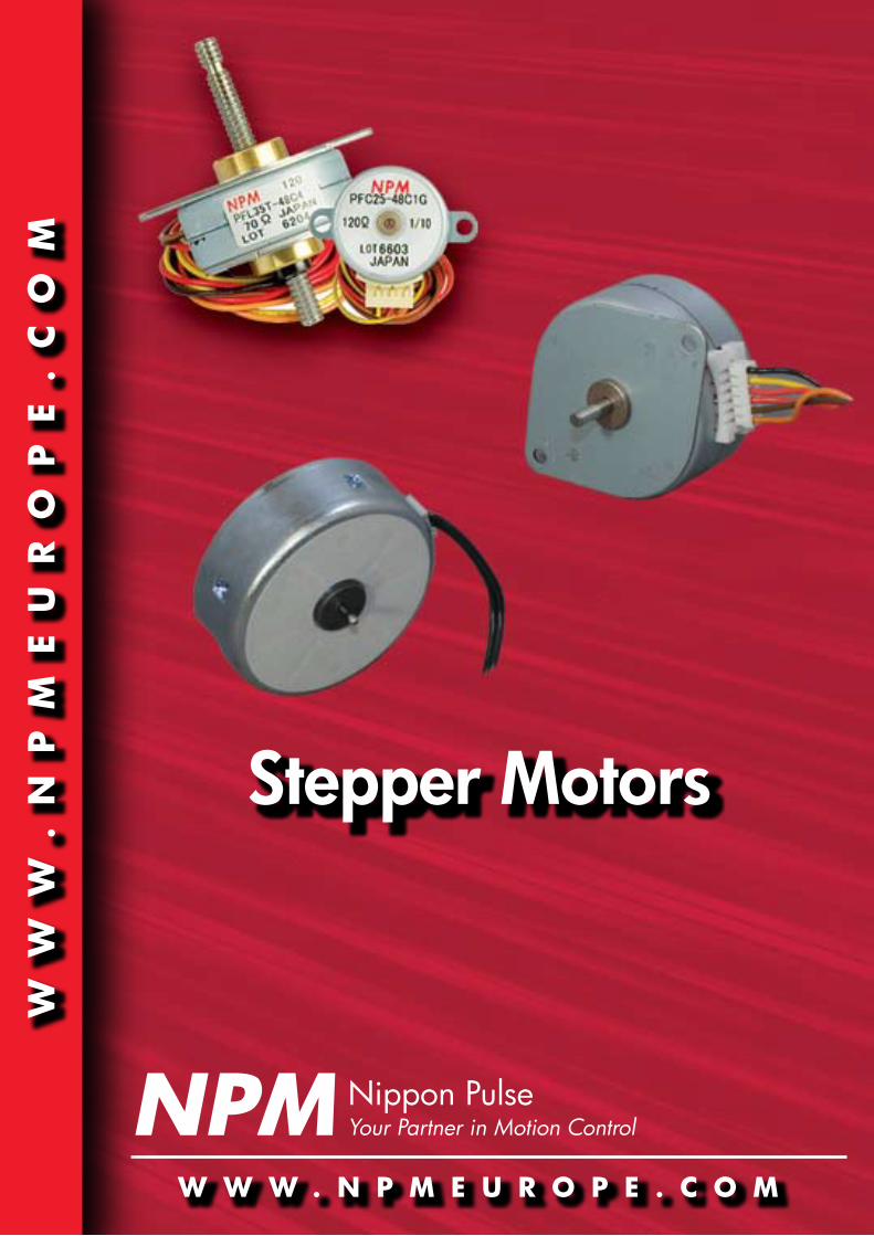
Stepper Motors
Nippon Pulse
w w w . n p m e u r o p e . c o m
ww
w.
np
me
ur
op
e.
co
m
npm Your Partner in Motion Control
CapacitorWith reversible synchronous motors, that can rotate both clockwise and counterclockwise, the rotor is moved by shifting the phase by 90°. Thus, a synchronous mo-tor requires a capacitor. The capacity depends on motor model, rated voltage, and supply frequency. The capaci-tor should also withstand a voltage of greater than two times the rated voltage of the motor. Continuous RatingSpecifications are continuously applicable to the rated output.
Dielectric StrengthThe maximum voltage between the case and the coils that can be sustained for one minute without damaging the motor.· 500Vac for one minute with operating voltage <30V· 1000Vac for one minute with operating voltage 30-150V· 1500Vac for one minute with operating voltage >150V
Intermittent RatingSpecifications are applicable for a specific time length to the rated output.
Motor SpeedNumber of revolutions per minute, which is determined by the number of rotor poles and supply frequency.
Operating Temperature RangeAmbient temperature range in which the motor can nor-mally be driven.
Operating Voltage RangeThe voltage range in which the motor can normally be driven.
Rotating DirectionViewed from the output shaft, clockwise rotation is la-beled CW, counterclockwise rotation CCW.
Rated CurrentCurrent at which the motor is rated for constant current drives (PWM, chopper).
Rated VoltageVoltage at which the motor is rated for constant voltage drives.
Temperature RiseThe temperature of the motor rises whenever power is applied. Temperature rise is determined by applying the motor’s rated voltage and measuring the increased coil resistance or the change in surface temperature of the motor.
nippon pulse Stepper motors
ASI base unit for current (ampere)
ACAlternating current
CCWCounterclockwise
CWClockwise
DCDirect Current
HzSI induced unit for frequency (cycles per second)
KSI base unit for temperature (Kelvin); often used for temperature rise
PPSPulses per second
RPMRevolutions per minute
VSI induced unit for voltage (volts)
Terminology Abbreviations/units
OD(mm) Tin-Can
Synchronous Linear StepperDual Direction Single Direction
20 PFCU20 -- --
25 PF(C)25PFCU25
PTM-24P -- PFCL25
35 PF35PF35T
PTM-24MPTM-24T
PTM-24B PFL35T
42 PF(C)42PFC42H
PF(C)42T
PTM24HPTMC-24S2
PTM-12KPTM-12E
55 PF(C)55PFC55H
PTM-24F --
Tin-can models by outer Diameter
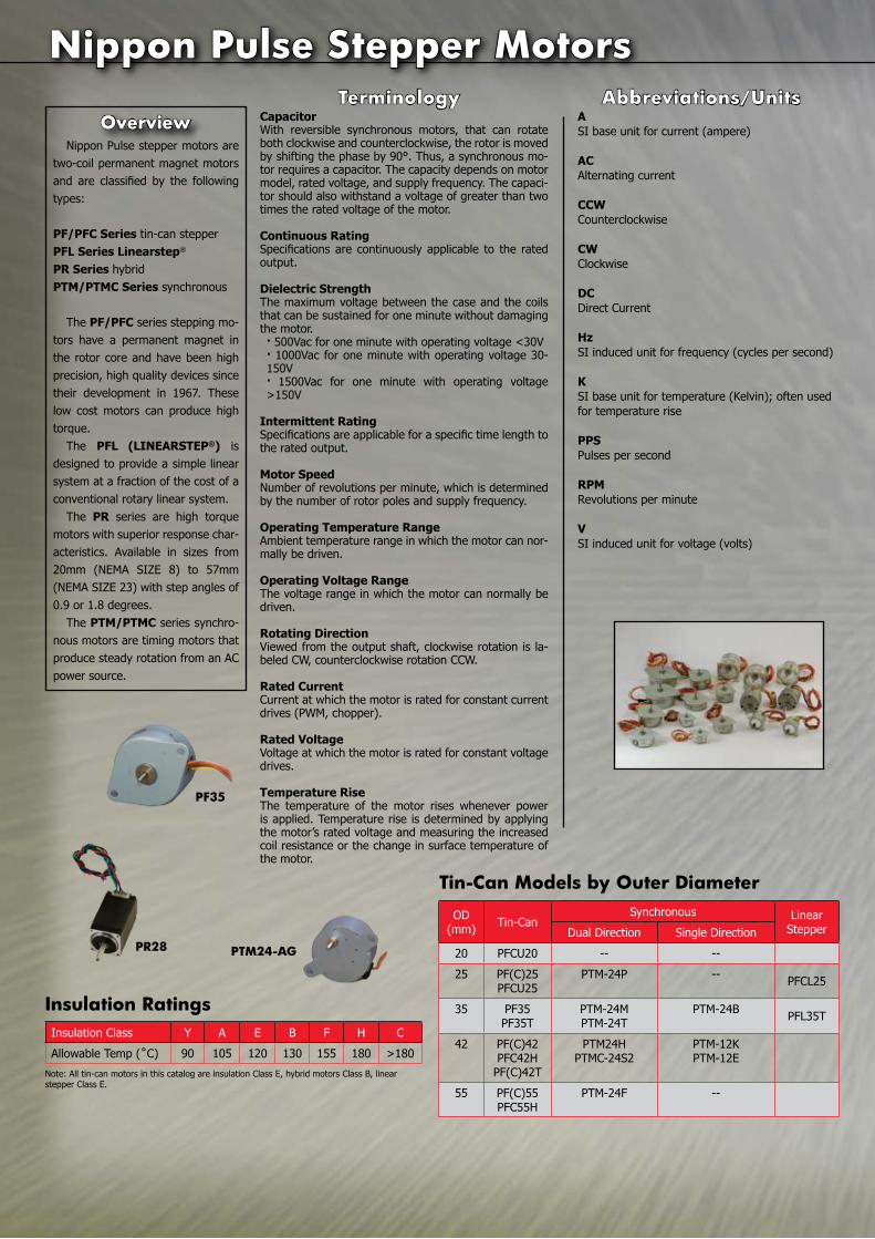
Nippon Pulse stepper motors are two-coil permanent magnet motors and are classified by the following types:
PF/PFC Series tin-can stepperPFL Series Linearstep®
PR Series hybridPTM/PTMC Series synchronous
The PF/PFC series stepping mo-tors have a permanent magnet in the rotor core and have been high precision, high quality devices since their development in 1967. These low cost motors can produce high torque.
The PFL (LINEARSTEP®) is designed to provide a simple linear system at a fraction of the cost of a conventional rotary linear system.
The PR series are high torque motors with superior response char-acteristics. Available in sizes from 20mm (NEMA SIZE 8) to 57mm (NEMA SIZE 23) with step angles of 0.9 or 1.8 degrees.
The PTM/PTMC series synchro-nous motors are timing motors that produce steady rotation from an AC power source.
overview
pF35
pr28 pTm24-AG
Insulation Class Y A E B F H C
Allowable Temp (˚C) 90 105 120 130 155 180 >180
Insulation ratings
Note: All tin-can motors in this catalog are insulation Class E, hybrid motors Class B, linear stepper Class E.
Y o u r P a r t n e r I n M o t i o n C o n t r o l www.npmeurope.com
Tin-can Steppers
�
Table of contentsTin-Can Steppers ............................................ 2-13Stepper Motor Specifications .....................................2PFCU20 ....................................................................3PFCU25 ....................................................................4PF25 ........................................................................5PF35 ........................................................................6PF35T ......................................................................7PF35TH ....................................................................8PF42 ........................................................................9PFC42H..................................................................10PF(C)42T ...............................................................11PF(C)55 .................................................................12PFC55H..................................................................13Geared Stepper Dimensions ....................................14
Linear Stepper Motors .................................. 15-17Linear Stepper Motor Specifications..........................15PFCL25 ..................................................................16PFL35T ..................................................................17
Hybrid Motors ............................................... 18-24Hybrid Motor Specifications .....................................18PR20 (NEMA 8) ......................................................19PR28 (NEMA 11) .....................................................20PR42 (NEMA 17) ................................................ 21-22PR57 (NEMA 23) ................................................ 23-24
Synchronous Motors ..................................... 25-34Synchronous Motor Specifications ............................25PTM-24F ................................................................26PTM-24B ................................................................27PTM-24P ................................................................28PTM-24M ...............................................................29PTM-24H ................................................................30PTM-24T ................................................................31PTM-24S2 ..............................................................32PTM-12K ................................................................33PTM-12E ................................................................34
Board Level Controllers .............................................35Custom Specification Form ........................................36
www.nipponpulse.com
Since its founding in 1952, Nippon Pulse has supplied high-quality products to a wide range of industries as a total motion control provid-er of precision motors, drivers, controllers, actuators and mechatronic systems. Nippon Pulse has always strived not only to satisfy, but also to impress its customers through the highest Quality, Value, Technol-ogy, Responsiveness and Reliability.
Nippon Pulse offers a superior technical advantage in various fields demanding greater motion control precision and state-of-the-art prod-ucts. As a result, Nippon Pulse has grown into a major worldwide sup-plier of motion control products. Nippon Pulse conducts business glob-ally through multiple subsidiaries, sales offices, and local distributors.
About nippon pulse
[email protected]: 1-540-633-1677
fax: 1-540-633-1674
nippon pulse Stepper motors
From Nippon Pulse’s Radford, Va. facility, most sample requests can be filled within a 24-hour period, allowing customers to test the product before making a large com-mitment. Nippon Pulse sales engineers work closely with each customer to completely understand the project and to provide the most appropriate solution. The Nippon Pulse model shop can then produce a high-quality sample to specification.
Nippon Pulse America, Inc. is located in a 5,000 square foot facility in Radford, Virginia and from this location is able to serve customers in North and South America as well as Europe.
prototyping
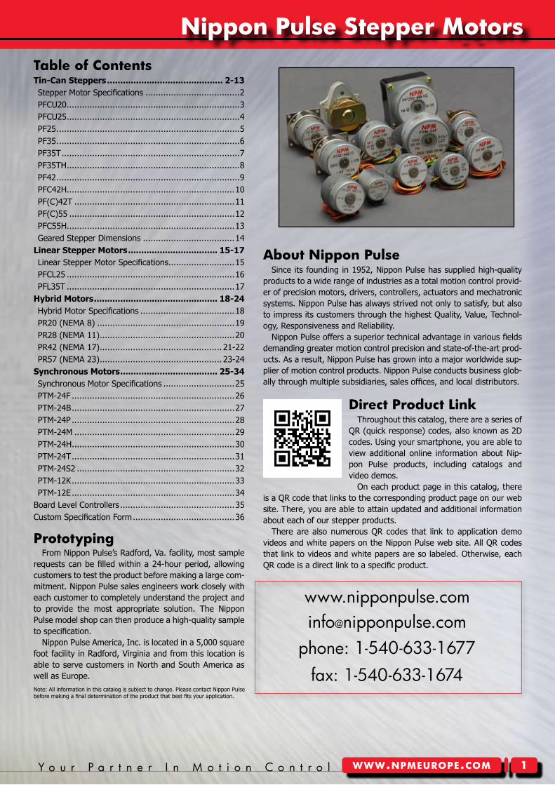
Throughout this catalog, there are a series of QR (quick response) codes, also known as 2D codes. Using your smartphone, you are able to view additional online information about Nip-pon Pulse products, including catalogs and video demos.
On each product page in this catalog, there is a QR code that links to the corresponding product page on our web site. There, you are able to attain updated and additional information about each of our stepper products.
There are also numerous QR codes that link to application demo videos and white papers on the Nippon Pulse web site. All QR codes that link to videos and white papers are so labeled. Otherwise, each QR code is a direct link to a specific product.
Direct product Link
Note: All information in this catalog is subject to change. Please contact Nippon Pulse before making a final determination of the product that best fits your application.
Tin-can Steppers
2 N i p p o n P u l s ewww.npmeurope.com
Unipolar Bipolar
Number of Transistors 1 2
To ensure the same temperature rise of motor
CurrentTorqueHigh-speed performanceVoltage
1111
1/√2√20.5√2
To obtain same torque
CurrentTemperature riseHigh-speed performanceVoltage
1111
0.50.50.51
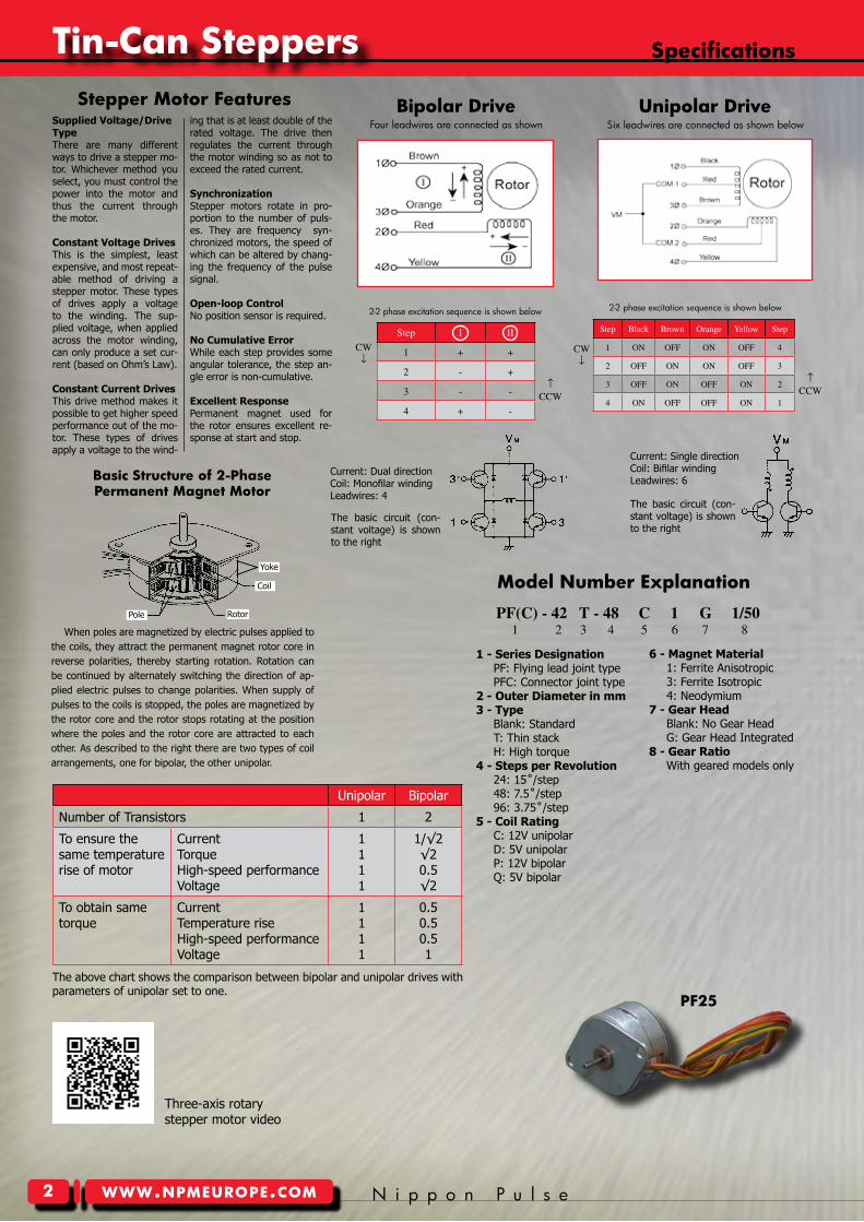
Step I II
1 + +
2 - +
3 - -
4 + -
CW↓
↑CCW
Bipolar Drive unipolar Drive
Step Black Brown Orange Yellow Step
1 ON OFF ON OFF 4
2 OFF ON ON OFF 3
3 OFF ON OFF ON 2
4 ON OFF OFF ON 1
CW↓
↑CCW
PF(C) - 42 T - 48 C 1 G 1/50 1 2 3 4 5 6 7 8
1 - Series Designation PF: Flying lead joint type PFC: Connector joint type2 - Outer Diameter in mm3 - Type Blank: Standard T: Thin stack H: High torque4 - Steps per Revolution 24: 15˚/step 48: 7.5˚/step 96: 3.75˚/step5 - Coil Rating C: 12V unipolar D: 5V unipolar P: 12V bipolar Q: 5V bipolar
Specifications
model number explanation
The above chart shows the comparison between bipolar and unipolar drives with parameters of unipolar set to one.
6 - Magnet Material 1: Ferrite Anisotropic 3: Ferrite Isotropic 4: Neodymium7 - Gear Head Blank: No Gear Head G: Gear Head Integrated8 - Gear Ratio With geared models only
pF25
2-2 phase excitation sequence is shown below 2-2 phase excitation sequence is shown below
Four leadwires are connected as shown Six leadwires are connected as shown below
The basic circuit (con-stant voltage) is shown to the right
Current: Single directionCoil: Bifilar windingLeadwires: 6
The basic circuit (con-stant voltage) is shown to the right
Current: Dual directionCoil: Monofilar windingLeadwires: 4
When poles are magnetized by electric pulses applied to the coils, they attract the permanent magnet rotor core in reverse polarities, thereby starting rotation. Rotation can be continued by alternately switching the direction of ap-plied electric pulses to change polarities. When supply of pulses to the coils is stopped, the poles are magnetized by the rotor core and the rotor stops rotating at the position where the poles and the rotor core are attracted to each other. As described to the right there are two types of coil arrangements, one for bipolar, the other unipolar.
Basic Structure of 2-phasepermanent magnet motor
Supplied Voltage/Drive TypeThere are many different ways to drive a stepper mo-tor. Whichever method you select, you must control the power into the motor and thus the current through the motor.
Constant Voltage DrivesThis is the simplest, least expensive, and most repeat-able method of driving a stepper motor. These types of drives apply a voltage to the winding. The sup-plied voltage, when applied across the motor winding, can only produce a set cur-rent (based on Ohm’s Law).
Constant Current DrivesThis drive method makes it possible to get higher speed performance out of the mo-tor. These types of drives apply a voltage to the wind-
ing that is at least double of the rated voltage. The drive then regulates the current through the motor winding so as not to exceed the rated current.
SynchronizationStepper motors rotate in pro-portion to the number of puls-es. They are frequency syn-chronized motors, the speed of which can be altered by chang-ing the frequency of the pulse signal.
Open-loop ControlNo position sensor is required.
No Cumulative ErrorWhile each step provides some angular tolerance, the step an-gle error is non-cumulative.
Excellent ResponsePermanent magnet used for the rotor ensures excellent re-sponse at start and stop.
Stepper motor Features
Yoke
Coil
RotorPole
Three-axis rotary stepper motor video
Y o u r P a r t n e r I n M o t i o n C o n t r o l www.npmeurope.com
Tin-can Steppers
3
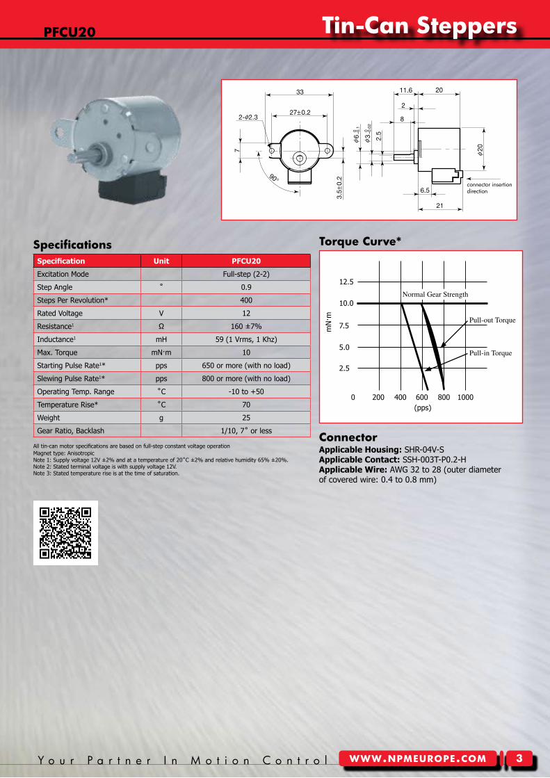
pFcu20
Specification Unit PFCU20
Excitation Mode Full-step (2-2)
Step Angle ˚ 0.9
Steps Per Revolution* 400
Rated Voltage V 12
Resistance1 Ω 160 ±7%
Inductance1 mH 59 (1 Vrms, 1 Khz)
Max. Torque mN·m 10
Starting Pulse Rate1* pps 650 or more (with no load)
Slewing Pulse Rate1* pps 800 or more (with no load)
Operating Temp. Range ˚C -10 to +50
Temperature Rise* ˚C 70
Weight g 25
Gear Ratio, Backlash 1/10, 7˚ or less
Note 1: Supply voltage 12V ±2% and at a temperature of 20˚C ±2% and relative humidity 65% ±20%.Note 2: Stated terminal voltage is with supply voltage 12V.Note 3: Stated temperature rise is at the time of saturation.
Torque curve*Specifications
connectorApplicable Housing: SHR-04V-SApplicable Contact: SSH-003T-P0.2-HApplicable Wire: AWG 32 to 28 (outer diameter of covered wire: 0.4 to 0.8 mm)
connector insertion direction
Pull-outTorque
Pull-inTorque
Pulse Rate
Torq
ue
NormalGearStrength
All tin-can motor specifications are based on full-step constant voltage operationMagnet type: Anisotropic
200 400 600 800 1000(pps)
0
2.5
5.0
7.5
10.0
12.5
mN
·m
Tin-can Steppers
4 N i p p o n P u l s ewww.npmeurope.com
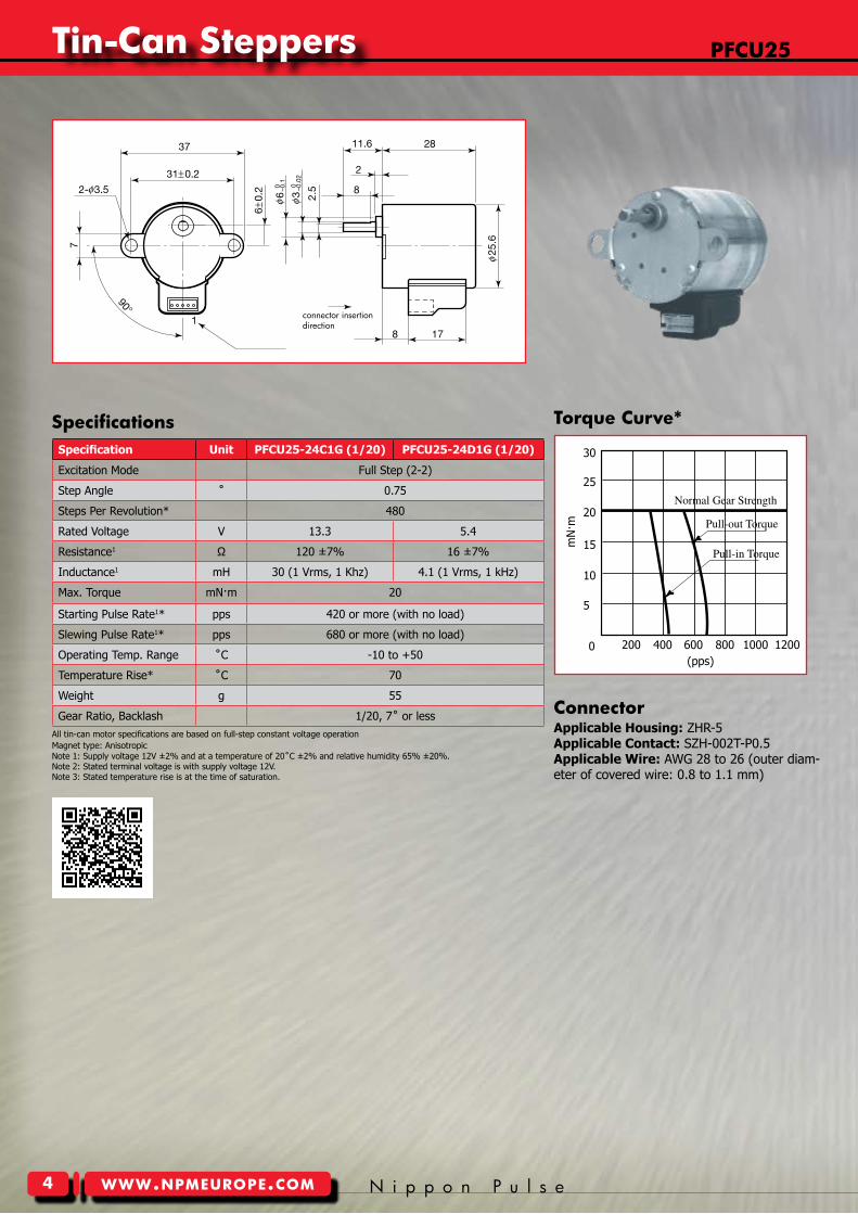
pFcu25
Specification Unit PFCU25-24C1G (1/20) PFCU25-24D1G (1/20)
Excitation Mode Full Step (2-2)
Step Angle ˚ 0.75
Steps Per Revolution* 480
Rated Voltage V 13.3 5.4
Resistance1 Ω 120 ±7% 16 ±7%
Inductance1 mH 30 (1 Vrms, 1 Khz) 4.1 (1 Vrms, 1 kHz)
Max. Torque mN·m 20
Starting Pulse Rate1* pps 420 or more (with no load)
Slewing Pulse Rate1* pps 680 or more (with no load)
Operating Temp. Range ˚C -10 to +50
Temperature Rise* ˚C 70
Weight g 55
Gear Ratio, Backlash 1/20, 7˚ or less
Note 1: Supply voltage 12V ±2% and at a temperature of 20˚C ±2% and relative humidity 65% ±20%.Note 2: Stated terminal voltage is with supply voltage 12V.Note 3: Stated temperature rise is at the time of saturation.
Specifications
connectorApplicable Housing: ZHR-5Applicable Contact: SZH-002T-P0.5Applicable Wire: AWG 28 to 26 (outer diam-eter of covered wire: 0.8 to 1.1 mm)
connector insertion direction
Torque curve*
NormalGearStrength
Pull-outTorque
Pull-inTorque
All tin-can motor specifications are based on full-step constant voltage operationMagnet type: Anisotropic
200 400 600 800 1000 1200
5
10
15
20
25
30
(pps)
mN
·m
0
Y o u r P a r t n e r I n M o t i o n C o n t r o l www.npmeurope.com
Tin-can Steppers
5
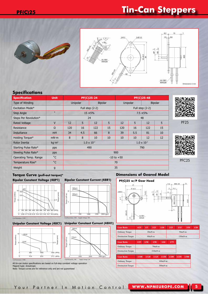
Bipolar constant current (48r�)
unipolar constant current (48H�)
10
340mA
230mA
5
1000 2000 3000(pps)
Torq
ue(
mN
·m)
0
2000(pps)150010005000
5
10
300mA
200mA
Torq
ue(
mN
·m)
Coil Resistance: 35Ω Supply Voltage: 24V
Coil Resistance: 34Ω Supply Voltage: 24V
pF(c)25
unipolar constant Voltage (48c�)
Bipolar constant Voltage (48p�)
Nippon Pulse America, Inc.a subsidiary of Nippon Pulse Motor Co., Ltd.
www.nipponpulse.com1-540-633-1677
PF25 Tin-Can Stepper with Gearhead (P Type)
Dimensions in mm
2-Ø3.5
MAX. 26 (1)11.6
11.32
1
MAX
. Ø 2
5.6
-0.1
0Ø
6
-0.0
2 0
Ø3 2.5
8
Ø 2
5
6 ±
0.2
2- 7
37
31 ±0.2
200
±10
(7) AWG28
UL1061
pF(c)25 w/p Gear Head
Note: Torque curves are for reference only and are not guaranteed
Gear Ratio 6/25 1/5 3/25 1/10 2/25 1/15 3/50 1/20
OrdinaryTorque 20mN·m 50mN·m
DestructionTorque 60mN·m 150mN·m
Gear Ratio 1/100 1/120 1/125 1/150 1/200 1/250 1/300
OrdinaryTorque 100mN·m
DestructionTorque 300mN·m
Gear Ratio 1/25 1/30 1/50 1/60 1/75
OrdinaryTorque 70mN·m
DestructionTorque 210mN·m
Torque curve (pull-out torque)* Dimensions of Geared model
Specification Unit PF(C)25-24 PF(C)25-48
Type of Winding Unipolar Bipolar Unipolar Bipolar
Excitation Mode* Full step (2-2) Full step (2-2)
Step Angle ˚ 15 ±5% 7.5 ±5%
Steps Per Revolution* 24 48
Rated Voltage V 12 5 12 5 12 5 12 5
Resistance Ω 120 16 122 15 120 16 122 15
Inductance mH 34 4.5 66 8 39 5.5 81 10
Holding Torque* mN·m 8 8 10 10 10 10 12 12
Rotor Inertia kg·m2 1.0 x 10⁻⁷ 1.0 x 10⁻⁷
Starting Pulse Rate* pps 490 790
Slewing Pulse Rate* pps 900
Operating Temp. Range ˚C -10 to +50
Temperature Rise* ˚C 70
Weight g 35
Coil Resistance: 120Ω
Coil Resistance: 122Ω
Specifications
1.4
0.71
Torq
ue (o
z•in
)
Nippon Pulse America, Inc.a subsidiary of Nippon Pulse Motor Co., Ltd.
www.nipponpulse.com1-540-633-1677
5
10
Torq
ue (m
N•m
) 25.6V
12.8V
PF25-48C1 w/ Unipolar Constant Voltage
0 20.8 31.3 (RPS)10.4
0 500 1000 1500 (PPS)
Driver: PS-2LD-5Excitation: Full-stepResistance: 120ohm
Nippon Pulse America, Inc.a subsidiary of Nippon Pulse Motor Co., Ltd.
www.nipponpulse.com1-540-633-1677
2-Ø 3.32-R 3
1
1.5
30°
720
0 ±10
Ø7
-0.1
0
Ø25
158.2
0.8
32 ±
0.2
38
Ø2
-0.0
1 0
UL1061AWG28
PF25 Tin-Can Stepper
Dimensions in mm
Nippon Pulse America, Inc.a subsidiary of Nippon Pulse Motor Co., Ltd.
www.nipponpulse.com1-540-633-1677
PFC25 Tin-Can Stepper
Dimensions in mm
UL1061AWG28
(7)
1510
200
±10
5
R1430°
1.52-R3 2-Ø3.3
32 ±
0.2
38
Ø7
-0.10
Ø2
-0.0
10
8.2 15 1
0.8
5.410
Ø25
All tin-can motor specifications are based on full-step constant voltage operationMagnet type: Anisotropic
1.4
Torq
ue (o
z•in
)
Nippon Pulse America, Inc.a subsidiary of Nippon Pulse Motor Co., Ltd.
www.nipponpulse.com1-540-633-1677
10
Torq
ue (m
N•m
)
24V
15V
12V
0.715
PF25-48P1 w/ Bipolar Constant Voltage
0 100 200 300 400 500 600 700 800 900 (PPS)
0 2.08 12.5 18.814.6 (RPS)4.17 6.25 8.33 10.4 16.7
Driver: CD-404B1Excitation: Full-stepResistance: 122ohm
PF25
PFC25
Tin-can Steppers
� N i p p o n P u l s ewww.npmeurope.com
pF35
unipolar constant Voltage (48c�)
Bipolar constant Voltage (48p�)
unipolar constant current (4807�)
Bipolar constant current (48�8�)pF35 w/H Gear Head
Note: Torque curves are for reference only and are not guaranteed
Nippon Pulse America, Inc.a subsidiary of Nippon Pulse Motor Co., Ltd.
www.nipponpulse.com1-540-633-1677
PF35 Tin-Can Stepper with Gearhead (H Type)
Dimensions in mm
UL1007AWG28
(10)
36.6 (max)
10
15
136 ±0.2
43.5MAX(4)
16
4-Ø3.5
2
36±0
.2
310
±15
10±0
.2
Ø10
±0.1
Ø5
-0.0
50
4.5
MA
X Ø
43.
5
Ø 3
5
Dimensions of Geared model Torque curve (pull-out torque)*
Gear Ratio 6/25 1/5 3/25 1/10
OrdinaryTorque 200mN·m
DestructionTorque 600mN·m
Gear Ratio 1/30 1/50 1/60 2/125 1/75
OrdinaryTorque 300mN·m
DestructionTorque 900mN·m
Gear Ratio 2/25 1/15 3/50 1/20 1/25
OrdinaryTorque 250mN·m
DestructionTorque 750mN·m
Nippon Pulse America, Inc.a subsidiary of Nippon Pulse Motor Co., Ltd.
www.nipponpulse.com1-540-633-1677
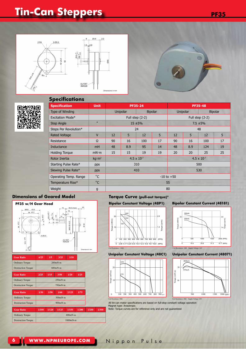
PF35 Tin-Can Stepper
Dimensions in mm
30°
UL1007AWG28
Ø35
310
±15
2.29
1.5 0.8
20.6
(10)
2-R4 2-Ø3.5
42 ±
0.2
50
Ø10
0 -0.1
Ø2
0 -0.0
1
Specification Unit PF35-24 PF35-48
Type of Winding Unipolar Bipolar Unipolar Bipolar
Excitation Mode* Full step (2-2) Full step (2-2)
Step Angle ˚ 15 ±5% 7.5 ±5%
Steps Per Revolution* 24 48
Rated Voltage V 12 5 12 5 12 5 12 5
Resistance Ω 90 16 100 17 90 16 100 17
Inductance mH 48 8.9 95 14 48 8.9 124 19
Holding Torque mN·m 15 15 19 19 20 20 25 25
Rotor Inertia kg·m2 4.5 x 10⁻⁷ 4.5 x 10⁻⁷
Starting Pulse Rate* pps 310 500
Slewing Pulse Rate* pps 410 530
Operating Temp. Range ˚C -10 to +50
Temperature Rise* ˚C 55
Weight g 80
PF35-48P1 w/ Bipolar Constant Voltage
Nippon Pulse America, Inc.a subsidiary of Nippon Pulse Motor Co., Ltd.
www.nipponpulse.com1-540-633-1677
10
20
Torq
ue (m
N•m
)
24V
12V
15V
1.4
2.8
Torq
ue (o
z•in
)
0 100 200 300 400 500 600 700 800 900 (PPS)
0 2.08 12.5 18.814.6 (RPS)4.17 6.25 8.33 10.4 16.7
Driver: CD-404B1Excitation: Full-stepResistance: 100ohm
Nippon Pulse America, Inc.a subsidiary of Nippon Pulse Motor Co., Ltd.
www.nipponpulse.com1-540-633-1677
20
10
Torq
ue (m
N•m
)
300mA
200mA
PF35-48C1 w/ Unipolar Chopper Drive
0 10.4 20.8 41.731.3 (RPS)
2.8
1.4 Torq
ue (o
z•in
)
(PPS)0 500 1000 1500 2000
Driver: BCD4020UTVoltage: 24VDCExcitation: Full-stepResistance: 90ohm
2000(pps)15001000500
20
10
460mA
355mA
Torq
ue(
mN
·m)
100 200 300 400 500 600 700 800 900(pps)0
10
20
24V
12V
Torq
ue(
mN
·m)
Coil Resistance: 100Ω Coil Resistance: 18Ω Supply Voltage: 24V
Coil Resistance: 90Ω Coil Resistance: 20Ω Supply Voltage: 24V
Specifications
All tin-can motor specifications are based on full-step constant voltage operationMagnet type: Anisotropic
Gear Ratio 1/100 1/120 1/125 1/150 1/200 1/250 1/300
OrdinaryTorque 400mN·m
DestructionTorque 1800mN·m
Y o u r P a r t n e r I n M o t i o n C o n t r o l www.npmeurope.com
Tin-can Steppers
7
unipolar constant Voltage (48c�)
Bipolar constant Voltage (48r�)
unipolar constant current (48D�)
Bipolar constant current (48Q�)pF35T w/m Gear Head
Dimensions of Geared model Torque curve (pull-out torque)*
Gear Ratio 1/5 1/6 1/10 1/18 1/30
OrdinaryTorque 100mN·m 200mN·m
DestructionTorque 300mN·m 600mN·m
Gear Ratio 1/125 1/150 1/180 1/200 1/270 1/300
OrdinaryTorque 600mN·m
DestructionTorque 1800mN·m
Gear Ratio 1/40 1/50 1/60 1/75 1/90 1/100 1/120
OrdinaryTorque 300mN·m
DestructionTorque 900mN·m
Nippon Pulse America, Inc.a subsidiary of Nippon Pulse Motor Co., Ltd.
www.nipponpulse.com1-540-633-1677
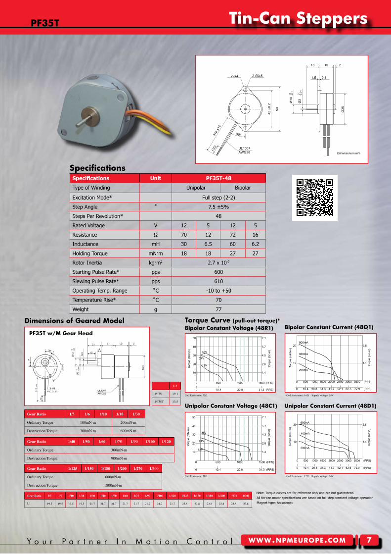
PF35T Tin-Can Stepper
Dimensions in mm
2-R4 2-Ø3.5
310
±15
(10) UL1007
AWG28
30°
42 ±
0.2
50
13 15 2
1.5 0.8
Ø10
-0.10
Ø2
-0.0
10
Ø35
PF35T-48R1 w/ Bipolar Constant Voltage
36V
24V
12VTorq
ue (m
N•m
)
2.8
1.4
Torq
ue (o
z•in
)
Nippon Pulse America, Inc.a subsidiary of Nippon Pulse Motor Co., Ltd.
www.nipponpulse.com1-540-633-1677
0 20.8 31.3 (RPS)10.4
0 500 1000 1500 (PPS)
50
40
30
20
10
4.5
5.7
7.1
Driver: CD-404B1Excitation: Full-stepResistance: 72ohm
20
10
500mA
350mA
250mA
Torq
ue (m
N•m
)
0 500 1000 1500 2000 2500 3000 3500 (PPS)
2.8
1.4
Torq
ue (o
z•in
)
Nippon Pulse America, Inc.a subsidiary of Nippon Pulse Motor Co., Ltd.
www.nipponpulse.com1-540-633-1677
0 20.8 31.3 (RPS)10.4 41.7 52.1 62.5 72.9
PF35T-48Q1 w/ Bipolar Chopper DriveDriver: BCD420B3Voltage: 24VDCExcitation: Full-stepResistance: 16ohm
PF35T-48C1 w/ Unipolar Constant Voltage
36V
24V
12V
Torq
ue (m
N•m
)
50
40
30
20
10
Nippon Pulse America, Inc.a subsidiary of Nippon Pulse Motor Co., Ltd.
www.nipponpulse.com1-540-633-1677
0 20.8 31.3 (RPS)10.4
0 500 15001000 (PPS)
Torq
ue (o
z•in
)
7.1
5.7
4.3
2.8
1.4
Driver: PS-2LD-5Excitation: Full-stepResistance: 70ohm
PF35T-48D1 w/ Unipolar Chopper Drive
20
10
600mA
400mA
300mA
Torq
ue (m
N•m
)
2.8
1.4
Torq
ue (o
z•in
)
0 500 1000 1500 2000 2500 3000 3500 (PPS)
Nippon Pulse America, Inc.a subsidiary of Nippon Pulse Motor Co., Ltd.
www.nipponpulse.com1-540-633-1677
0 20.8 31.3 (RPS)10.4 41.7 52.1 62.5 72.9
Driver: BCD4020UTVoltage: 24VDCExcitation: Full-stepResistance: 12ohm
Specifications Unit PF35T-48
Type of Winding Unipolar Bipolar
Excitation Mode* Full step (2-2)
Step Angle ˚ 7.5 ±5%
Steps Per Revolution* 48
Rated Voltage V 12 5 12 5
Resistance Ω 70 12 72 16
Inductance mH 30 6.5 60 6.2
Holding Torque mN·m 18 18 27 27
Rotor Inertia kg·m2 2.7 x 10⁻⁷
Starting Pulse Rate* pps 600
Slewing Pulse Rate* pps 610
Operating Temp. Range ˚C -10 to +50
Temperature Rise* ˚C 70
Weight g 77
Coil Resistance: 72Ω Coil Resistance: 16Ω Supply Voltage: 24V
Coil Resistance: 70Ω Coil Resistance: 12Ω Supply Voltage: 24V
Specifications
pF35T
Note: Torque curves are for reference only and are not guaranteed.All tin-can motor specifications are based on full-step constant voltage operationMagnet type: Anisotropic
Gear Ratio 1/5 1/6 1/10 1/18 1/30 1/40 1/50 1/60 1/75 1/90 1/100 1/120 1/125 1/150 1/180 1/200 1/270 1/300
L1 19.5 19.5 19.5 19.5 21.7 21.7 21.7 21.7 21.7 21.7 21.7 21.7 23.8 23.8 23.8 23.8 23.8 23.8
L2
PF35 19.1
PF35T 13.5
Tin-can Steppers
8 N i p p o n P u l s ewww.npmeurope.com
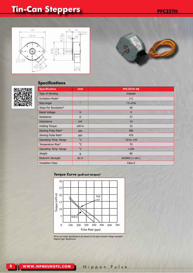
pFc35TH
Specification Unit PFC35TH-48
Type of Winding Unipolar
Excitation Mode* 2-2
Step Angle ˚ 7.5 ±5%
Steps Per Revolution* 48
Rated Voltage V 9
Resistance Ω 37
Inductance mH 14
Holding Torque mN·m 33
Starting Pulse Rate* pps 400
Slewing Pulse Rate* pps 470
Operating Temp. Range ˚C -10 to +50
Temperature Rise* ˚C 70
Operating Temp. Range ˚C +100
Weight g 80
Dielectric Strength AC·V AC500V (1 min.)
Insulation Class Class E
Torque curve (pull-out torque)*
Specifications
0 100
5
10
200 300 400 500 600 700
15
20
25
30
Torq
ue (m
N·m
)
Pulse Rate (pps)
Pull-out
Pull-in
All tin-can motor specifications are based on full-step constant voltage operationMagnet type: Neodymium
Y o u r P a r t n e r I n M o t i o n C o n t r o l www.npmeurope.com
Tin-can Steppers
�
unipolar constant Voltage (48c�)
Bipolar constant Voltage (48p�) Bipolar constant current (48Y�)
unipolar constant current (48I�)
pF42 w/H Gear Head
Nippon Pulse America, Inc.a subsidiary of Nippon Pulse Motor Co., Ltd.
www.nipponpulse.com1-540-633-1677
PF42 Tin-Can Stepper with Gearhead (H Type)
Dimensions in mm
UL1007AWG26
37.8
1
15
36±0.2
10
43.5MAX
4-Ø3.5
2
2.2
36±0
.2
310
±15
(10)
10±0
.2
Ø10
±0.1
Ø5
-0.0
50
4.5
Ø42
MA
X Ø
43.5
Note: Torque curves are for reference only and are not guaranteed.
Dimensions of Geared model Torque curve (pull-out torque)*
Gear Ratio 6/25 1/5 3/25 1/10 2/25 1/15 3/50 1/20 1/25
OrdinaryTorque 200mN·m 250mN·m
DestructionTorque 600mN·m 750mN·m
Gear Ratio 1/100 1/120 1/125 1/150 1/200 1/250 1/300
OrdinaryTorque 400mN·m
DestructionTorque 1200mN·m
Gear Ratio 1/30 1/50 1/60 2/125 1/75
OrdinaryTorque 300mN·m
DestructionTorque 900mN·m
Nippon Pulse America, Inc.a subsidiary of Nippon Pulse Motor Co., Ltd.
www.nipponpulse.com1-540-633-1677
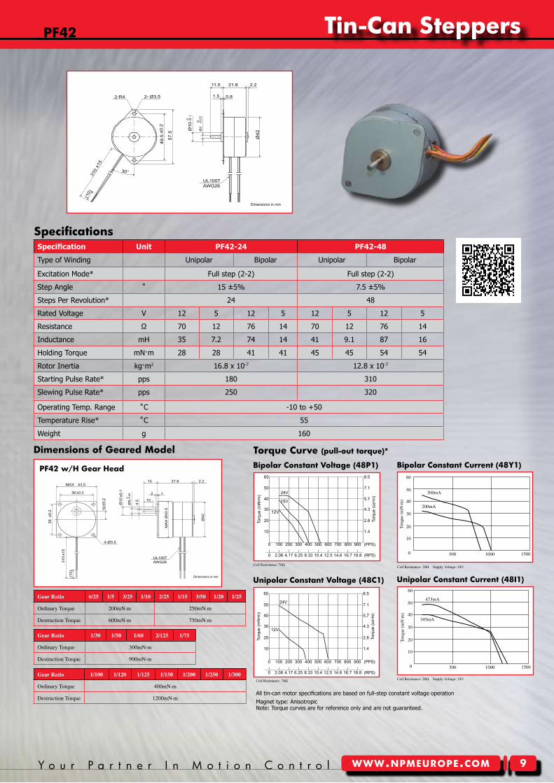
PF42 Tin Can Stepper
Dimensions in mm
UL1007AWG26
(10)
Ø10
0 -0.1
21.811.5
1.5 0.8
49.5
±0.2
Ø3
0 -0.0
1
310
±15
57.5
Ø42
2-R4 2- Ø3.5
30°
2.2
Specification Unit PF42-24 PF42-48
Type of Winding Unipolar Bipolar Unipolar Bipolar
Excitation Mode* Full step (2-2) Full step (2-2)
Step Angle ˚ 15 ±5% 7.5 ±5%
Steps Per Revolution* 24 48
Rated Voltage V 12 5 12 5 12 5 12 5
Resistance Ω 70 12 76 14 70 12 76 14
Inductance mH 35 7.2 74 14 41 9.1 87 16
Holding Torque mN·m 28 28 41 41 45 45 54 54
Rotor Inertia kg·m2 16.8 x 10⁻⁷ 12.8 x 10⁻⁷
Starting Pulse Rate* pps 180 310
Slewing Pulse Rate* pps 250 320
Operating Temp. Range ˚C -10 to +50
Temperature Rise* ˚C 55
Weight g 160
2.8
1.4
Torq
ue (o
z•in
)
Nippon Pulse America, Inc.a subsidiary of Nippon Pulse Motor Co., Ltd.
www.nipponpulse.com1-540-633-1677
10
20Torq
ue (m
N•m
)
4.330
5.740
7.150
8.560
0 100 200 300 400 500 600 700 800 900 (PPS)
0 2.08 12.5 18.814.6 (RPS)4.17 6.25 8.33 10.4 16.7
PF42-48C1 w/ Unipolar Constant Voltage
24V
12V
Driver: PS-2LD-5Excitation: Full-stepResistance: 70ohm
Nippon Pulse America, Inc.a subsidiary of Nippon Pulse Motor Co., Ltd.
www.nipponpulse.com1-540-633-1677
10
20Torq
ue (m
N•m
)
30
40
50
60
2.8
1.4
Torq
ue (o
z•in
)
4.3
5.7
7.1
8.5
0 100 200 300 400 500 600 700 800 900 (PPS)
0 2.08 12.5 18.814.6 (RPS)4.17 6.25 8.33 10.4 16.7
24V
12V
15V
PF42-48P1 w/ Bipolar Constant VoltageDriver: CD-404B1Excitation: Full-stepResistance: 76ohm
40
Torq
ue(
mN
·m)
50
60
30
10
0 500 1000
473mA
345mA
1500
20
40
Torq
ue(
mN
·m)
50
60
30
10
0
20
500 1000 1500
Coil Resistance: 76Ω
Coil Resistance: 20Ω Supply Voltage: 24VCoil Resistance: 70Ω
Coil Resistance: 20Ω Supply Voltage: 24V
Specifications
pF42
All tin-can motor specifications are based on full-step constant voltage operationMagnet type: Anisotropic
300mA
200mA
Tin-can Steppers
�0 N i p p o n P u l s ewww.npmeurope.com
pFc42H
unipolar constant Voltage (48c�)
Bipolar constant Voltage (48p�)
unipolar constant current (48D�)
Bipolar constant current (48Q�) pFc42H w/H Gear Head
Nippon Pulse America, Inc.a subsidiary of Nippon Pulse Motor Co., Ltd.
www.nipponpulse.com1-540-633-1677
PFC42H Tin-Can Stepper with Gearhead (H Type)
Dimensions in mm
36±0.2
43.5MAX
4-Ø3.5
36±0
.2
310
±15
10
10±0
.2
UL1007AWG26
37.8
1
15
10
2
2.2
Ø10
±0.1
Ø5
-0.0
50
4.5
Ø42
MA
X Ø
43.5
Note: Torque curves are for reference only and are not guaranteed.
Dimensions of Geared modelTorque curve (pull-out torque)*
Gear Ratio 6/25 1/5 3/25 1/10 2/25 1/15 3/50 1/20 1/25
OrdinaryTorque 200mN·m 250mN·m
DestructionTorque 600mN·m 750mN·m
Gear Ratio 1/100 1/120 1/125 1/150 1/200 1/250 1/300
OrdinaryTorque 400mN·m
DestructionTorque 1200mN·m
Gear Ratio 1/30 1/50 1/60 2/125 1/75
OrdinaryTorque 300mN·m
DestructionTorque 900mN·m
Nippon Pulse America, Inc.a subsidiary of Nippon Pulse Motor Co., Ltd.
www.nipponpulse.com1-540-633-1677
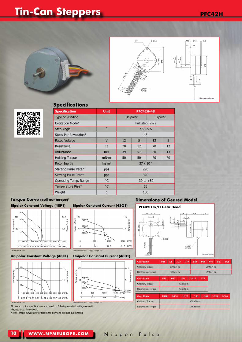
PFC42H Tin-Can Stepper
Dimensions in mm
4.5
21.8
3
Ø10
11.5 2.2
Ø42
0.81.5
9
Ø3
2-Ø 3.52-R 4
30°
310 ±
15
5.8
12.418
(10)
49.5
±0.2
57.5
UL1007AWG26
0 -0.1
0 -0.0
1
Specification Unit PFC42H-48
Type of Winding Unipolar Bipolar
Excitation Mode* Full step (2-2)
Step Angle ˚ 7.5 ±5%
Steps Per Revolution* 48
Rated Voltage V 12 5 12 5
Resistance Ω 70 12 70 12
Inductance mH 39 6.6 80 13
Holding Torque mN·m 50 50 70 70
Rotor Inertia kg·m2 27 x 10-7
Starting Pulse Rate* pps 290
Slewing Pulse Rate* pps 320
Operating Temp. Range ˚C -30 to +80
Temperature Rise* ˚C 55
Weight g 160
Nippon Pulse America, Inc.a subsidiary of Nippon Pulse Motor Co., Ltd.
www.nipponpulse.com1-540-633-1677
14.2
7.1
Torq
ue (o
z•in
)
50
100
Torq
ue (m
N•m
)
0 100 200 300 400 500 600 700 800 900 (PPS)
0 2.08 12.5 18.814.6 (RPS)4.17 6.25 8.33 10.4 16.7
36V
24V
12V
PFC42H-48P1 w/ Bipolar Constant VoltageDriver: PS-2LD-5Excitation: Full-stepResistance: 9ohm
Nippon Pulse America, Inc.a subsidiary of Nippon Pulse Motor Co., Ltd.
www.nipponpulse.com1-540-633-1677
0 20.8 31.3 (RPS)10.4
0 500 1000 1500 (PPS)
14.2
7.1
Torq
ue (o
z•in
)
50
100
Torq
ue (m
N•m
)
PFC42H-48Q1 w/ Bipolar Chopper Drive
600mA
400mA
300mA
Driver: BCD4020B3Voltage: 24VDCExcitation: Full-stepResistance: 12ohm
14.2
7.1
Torq
ue (o
z•in
)
Nippon Pulse America, Inc.a subsidiary of Nippon Pulse Motor Co., Ltd.
www.nipponpulse.com1-540-633-1677
50
100
Torq
ue (m
N•m
)
36V
24V
12V
PFC42H-48C1 w/ Unipolar Constant Voltage
0 100 200 300 400 500 600 700 800 900 (PPS)
0 2.08 12.5 18.814.6 (RPS)4.17 6.25 8.33 10.4 16.7
Driver: PS-2LD-5Excitation: Full-stepResistance: 70ohm
14.2
7.1
Torq
ue (o
z•in
)
Nippon Pulse America, Inc.a subsidiary of Nippon Pulse Motor Co., Ltd.
www.nipponpulse.com1-540-633-1677
50
100
Torq
ue (m
N•m
)
600mA
400mA
300mA
0 20.8 31.3 (RPS)10.4
0 500 1000 1500 (PPS)(2200pps)(2000pps)
PFC42H-48D1 w/ Unipolar Chopper DriveDriver: CD-4020UTVoltage: 24VDCExcitation: Full-stepResistance: 12ohm
Coil Resistance: 70Ω Coil Resistance: 12Ω Supply Voltage: 24V
Coil Resistance: 70Ω Coil Resistance: 12Ω Supply Voltage: 24V
Specifications
All tin-can motor specifications are based on full-step constant voltage operationMagnet type: Anisotropic
Y o u r P a r t n e r I n M o t i o n C o n t r o l www.npmeurope.com
Tin-can Steppers
��
unipolar constant Voltage (48c�)
Bipolar constant Voltage (48p�) Bipolar constant current (4827�)
uniplar constant current (4807�)
pF(c)42T w/H Gear Head
Nippon Pulse America, Inc.a subsidiary of Nippon Pulse Motor Co., Ltd.
www.nipponpulse.com1-540-633-1677
PF42T Tin-Can Stepper with Gearhead (H Type)
Dimensions in mm
43.5MAX
4-Ø3.5
Ø42
UL1007AWG28
1
15 30.9
10
2
2.2
Ø5 0 -0
.05
4.5
MA
X Ø
43.5
36 ±
0.2
310
±15
36 ±0.2
10 ±
0.2
Ø10
±0.
1
10
Note: Torque curves are for reference only and are not guaranteed.
Gear Ratio 6/25 1/5 3/25 1/10 2/25 1/15 3/50 1/20 1/25
OrdinaryTorque 200mN·m 250mN·m
DestructionTorque 600mN·m 750mN·m
Gear Ratio 1/100 1/120 1/125 1/150 1/200 1/250 1/300
OrdinaryTorque 400mN·m
DestructionTorque 1200mN·m
Gear Ratio 1/30 1/50 1/60 2/125 1/75
OrdinaryTorque 300mN·m
DestructionTorque 900mN·m
Dimensions of Geared model Torque curve (pull-out torque)*
Nippon Pulse America, Inc.a subsidiary of Nippon Pulse Motor Co., Ltd.
www.nipponpulse.com1-540-633-1677
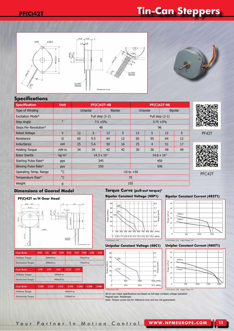
PF42T Tin-Can Stepper
Dimensions in mm
UL1007AWG28
Ø42
310±
15
115.9
30°
14.9
(10)
2-R4 2-Ø3.5
49.5
±0.
2
57.5
Ø3
0 -0.0
1
Ø10
0 -0.1
1.5 0.8
Specification Unit PF(C)42T-48 PF(C)42T-96
Type of Winding Unipolar Bipolar Unipolar Bipolar
Excitation Mode* Full step (2-2) Full step (2-2)
Step Angle ˚ 7.5 ±5% 3.75 ±5%
Steps Per Revolution* 48 96
Rated Voltage V 12 5 12 5 12 5 12 5
Resistance Ω 60 9.5 64 12 60 95 64 12
Inductance mH 25 5.6 50 16 25 4 51 17
Holding Torque mN·m 34 34 42 42 30 36 49 49
Rotor Inertia kg·m2 14.3 x 10⁻⁷ 14.8 x 10⁻⁷
Starting Pulse Rate* pps 345 450
Slewing Pulse Rate* pps 550 590
Operating Temp. Range ˚C -10 to +50
Temperature Rise* ˚C 70
Weight g 105
Nippon Pulse America, Inc.a subsidiary of Nippon Pulse Motor Co., Ltd.
www.nipponpulse.com1-540-633-1677
10
20Torq
ue (m
N•m
)
30
40
50
60
2.8
1.4
Torq
ue (o
z•in
)
4.3
5.7
7.1
8.5
0 100 200 300 400 500 600 700 800 900 (PPS)
0 2.08 12.5 18.814.6 (RPS)4.17 6.25 8.33 10.4 16.7
24V
15V
12V
PF42T-48P1 w/ Bipolar Constant VoltageDriver: CD-404B1Excitation: Full-stepResistance: 64ohm
2.8
1.4
Torq
ue (o
z•in
)
Nippon Pulse America, Inc.a subsidiary of Nippon Pulse Motor Co., Ltd.
www.nipponpulse.com1-540-633-1677
10
20
Torq
ue (m
N•m
)
PF42T-48C1 w/ Unipolar Constant Voltage
23V
11.5V
0 20.8 31.3 (RPS)10.4
0 500 1000 1500 (PPS)
4.330
5.740
7.150
8.560
Driver: PS-2LD-5Excitation: Full-stepResistance: 60ohm
40
Torq
ue(
mN
·m)
50
60
30
10
0
20
500 1000 1500 2000
460mA
345mA
0 500 1000 1500
40
Torq
ue(
mN
·m)
50
60
30
10
20
300mA
200mA
Coil Resistance: 64Ω Coil Resistance: 19Ω Supply Voltage: 24V
Coil Resistance: 60Ω Coil Resistance: 20Ω Supply Voltage: 24V
Specifications
pF(c)42T
All tin-can motor specifications are based on full-step constant voltage operation
Nippon Pulse America, Inc.a subsidiary of Nippon Pulse Motor Co., Ltd.
www.nipponpulse.com1-540-633-1677
PFC42T Tin-Can Stepper
Dimensions in mm
UL1007AWG28
0.8
57.5
39
(10)
5.8
310
±15
12.418
Ø42
Ø49
.5 ±
0.2
Ø10
0 -0.1
Ø3
0 -0.0
1
115.9 14.92-R4
30°
1.5
4.5
2-Ø3.5
Magnet type: Anisotropic
PF42T
PFC42T
Tin-can Steppers
�2 N i p p o n P u l s ewww.npmeurope.com
pF(c)55
unipolar constant Voltage (48c�)
Bipolar constant Voltage (48p�)
unipolar constant current (48D�)
Bipolar constant current (48Q�)pF(c)55 w/F Gear Head
Nippon Pulse America, Inc.a subsidiary of Nippon Pulse Motor Co., Ltd.
www.nipponpulse.com1-540-633-1677
PF55 Tin-Can Stepper with Gearhead (F Type)
Dimensions in mm
UL1007AWG24
10 ±
0.2
310
±15
60
(10)
4-P.C.D. 70
4-Ø4.5
Ø6
0 -0.0
2
Ø12
±0.
05
5.5
Ø55
12
5227
1.65 27
M40 x 40Screw
Note: Torque curves are for reference only and are not guaranteed.
Dimensions of Geared modelTorque curve (pull-out torque)*
Gear Ratio 6/25 1/5 3/25 1/10 2/25 1/15 3/50 1/20
OrdinaryTorque 400mN·m
DestructionTorque 1200mN·m
Gear Ratio 2/125 1/75 3/250 1/100 1/125 1/150 1/250 1/300
OrdinaryTorque 1000mN·m
DestructionTorque 3000mN·m
Gear Ratio 1/25 1/30 1/50 1/60
OrdinaryTorque 700mN·m
DestructionTorque 2100mN·m
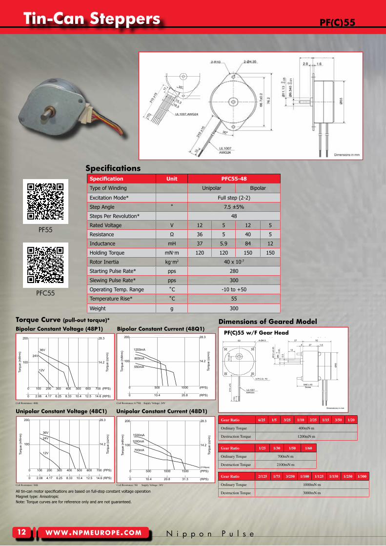
Specification Unit PFC55-48
Type of Winding Unipolar Bipolar
Excitation Mode* Full step (2-2)
Step Angle ˚ 7.5 ±5%
Steps Per Revolution* 48
Rated Voltage V 12 5 12 5
Resistance Ω 36 5 40 5
Inductance mH 37 5.9 84 12
Holding Torque mN·m 120 120 150 150
Rotor Inertia kg·m2 40 x 10-7
Starting Pulse Rate* pps 280
Slewing Pulse Rate* pps 300
Operating Temp. Range ˚C -10 to +50
Temperature Rise* ˚C 55
Weight g 300
Nippon Pulse America, Inc.a subsidiary of Nippon Pulse Motor Co., Ltd.
www.nipponpulse.com1-540-633-1677
28.3
14.2
Torq
ue (o
z•in
)
100
200
Torq
ue (m
N•m
) 36V
24V
12V
0 8.33 10.4 (RPS)2.08
0 100 400 500
12.5
600 (PPS)
PFC55-48P1 w/ Bipolar Constant Voltage
4.17
200
6.25
300
14.6
700
Driver: CD-404B1Excitation: Full-stepResistance: 40ohm
Nippon Pulse America, Inc.a subsidiary of Nippon Pulse Motor Co., Ltd.
www.nipponpulse.com1-540-633-1677
28.3
14.2
Torq
ue (o
z•in
)
100
200
Torq
ue (m
N•m
) 1200mA
800mA
550mA
0 20.8 (RPS)10.4
0 500 1000 (PPS)
PFC55-48Q1 w/ Bipolar Chopper DriveDriver: BCD420B3Voltage: 24VDCExcitation: Full-stepResistance: 6.75ohm
28.3
14.2
Torq
ue (o
z•in
)
Nippon Pulse America, Inc.a subsidiary of Nippon Pulse Motor Co., Ltd.
www.nipponpulse.com1-540-633-1677
100
200
Torq
ue (m
N•m
)
PFC55-48C1 w/ Unipolar Constant Voltage
0 100 200 300 400 500 600 700 (PPS)
0 2.08 12.5 14.6 (RPS)4.17 6.25 8.33 10.4
Driver: PS-2LD-5Excitation: Full-stepResistance: 36ohm
36V
24V
12V
28.3
14.2
Torq
ue (o
z•in
)
Nippon Pulse America, Inc.a subsidiary of Nippon Pulse Motor Co., Ltd.
www.nipponpulse.com1-540-633-1677
100
200
Torq
ue (m
N•m
) 1500mA
1000mA
700mA
0 20.8 31.3 (RPS)10.4
0 500 1000 1500 (PPS)(2100pps)
PFC55-48D1 w/ Unipolar Chopper DriveDriver: BCD4020UTVoltage: 24VDCExcitation: Full-stepResistance: 5ohm
Coil Resistance: 40Ω Coil Resistance: 6.75Ω Supply Voltage: 24V
Coil Resistance: 36Ω Coil Resistance: 5Ω Supply Voltage: 24V
Specifications
All tin-can motor specifications are based on full-step constant voltage operationMagnet type: Anisotropic
Nippon Pulse America, Inc.a subsidiary of Nippon Pulse Motor Co., Ltd.
www.nipponpulse.com1-540-633-1677
PFC55 Tin-Can Stepper
Dimensions in mm
UL1007,AWG24
4.5310
±15
11
9
66.7
±0.2
(10)
Ø11
.13
0 -0.0
5
1.6
Ø5576
.2
18.5
15.3
252-R10
30°
2.9
2.9
2-Ø3.418.5
Ø6.
345
0 -0.0
1PF55
PFC55
Y o u r P a r t n e r I n M o t i o n C o n t r o l www.npmeurope.com
Tin-can Steppers
�3
unipolar constant Voltage (48c�)
Bipolar constant Voltage (480��)
unipolar constant current (48D�)
Bipolar constant current (48S�)pFc55H w/F(BB) Gear Head
Nippon Pulse America, Inc.a subsidiary of Nippon Pulse Motor Co., Ltd.
www.nipponpulse.com1-540-633-1677
PFC55H Tin-Can Stepper with Gearhead (F Type)
Dimensions in mm
Ø6
0 -0.0
2
Ø12
±0.
05
UL1007AWG24
10 ±
0.2 5.
5
310
±15
60
Ø55
12
M4 x 40Screw
10
5327
1.65 27
P.C.D. 70
4-Ø4.5
Note: Torque curves are for reference only and are not guaranteed.
Gear Ratio 1/3 1/5 2/15 1/10 2/25 1/15 1/20
OrdinaryTorque 400mN·m 500mN·m 600mN·m 800mN·m
DestructionTorque 1200mN·m 1500mN·m 1800mN·m 2400mN·m
Gear Ratio 1/75 1/100 1/125 1/150 1/180
OrdinaryTorque 2500mN·m
DestructionTorque 7500mN·m
Gear Ratio 1/25 1/30 1/50 1/60
OrdinaryTorque 900mN·m 1100mN·m 1600mN·m
DestructionTorque 2700mN·m 3300mN·m 4800mN·m
Dimensions of Geared model Torque curve (pull-out torque)*
Nippon Pulse America, Inc.a subsidiary of Nippon Pulse Motor Co., Ltd.
www.nipponpulse.com1-540-633-1677
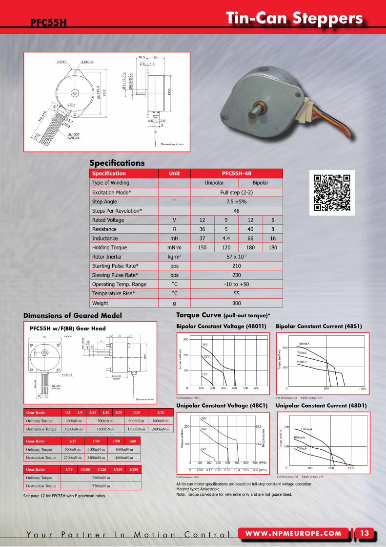
PFC55H Tin-Can Stepper
Dimensions in mm
UL1007AWG24
4.5310
±15
11
9
66.7
±0.2
(10)
Ø11
.13
0 -0.0
5
1.6
Ø55
76.2
18.5
15.3
262-R10
30°
2.9
2.9
2-Ø4.3518.5
Ø6.
345 0 -0
.01
Specification Unit PFC55H-48
Type of Winding Unipolar Bipolar
Excitation Mode* Full step (2-2)
Step Angle ˚ 7.5 ±5%
Steps Per Revolution* 48
Rated Voltage V 12 5 12 5
Resistance Ω 36 5 40 8
Inductance mH 37 4.4 66 16
Holding Torque mN·m 150 120 180 180
Rotor Inertia kg·m2 57 x 10-7
Starting Pulse Rate* pps 210
Slewing Pulse Rate* pps 230
Operating Temp. Range ˚C -10 to +50
Temperature Rise* ˚C 55
Weight g 300
Nippon Pulse America, Inc.a subsidiary of Nippon Pulse Motor Co., Ltd.
www.nipponpulse.com1-540-633-1677
0 100 200 300 400 500 600 700 (PPS)
0 2.08 12.5 14.6 (RPS)4.17 6.25 8.33 10.4
14.2
Torq
ue (o
z•in
)
100
Torq
ue (m
N•m
)
28.3200
36V
24V
12V
PFC55H-48D1 w/ Unipolar Constant VoltageDriver: PS-2LD-5Excitation: Full-stepResistance: 36ohm
Torq
ue(
mN
·m)
100
200
0 500 1000 1500
1500mA
1000mA
700mA
Torq
ue(
mN
·m)
100
200
500 1000
1000mA
700mA
500mA
Torq
ue(
mN
·m)
200
300
100
0 0100 200 300 400 500 600
36V
24V
12V
Coil Resistance: 40Ω Coil Resistance: 8Ω Supply Voltage: 24V
Coil Resistance: 36Ω Coil Resistance: 5Ω Supply Voltage: 24V
Specifications
pFc55H
All tin-can motor specifications are based on full-step constant voltage operationMagnet type: Anisotropic
See page 12 for PFC55H with F gearhead ratios
Tin-can Steppers
�4 N i p p o n P u l s ewww.npmeurope.com
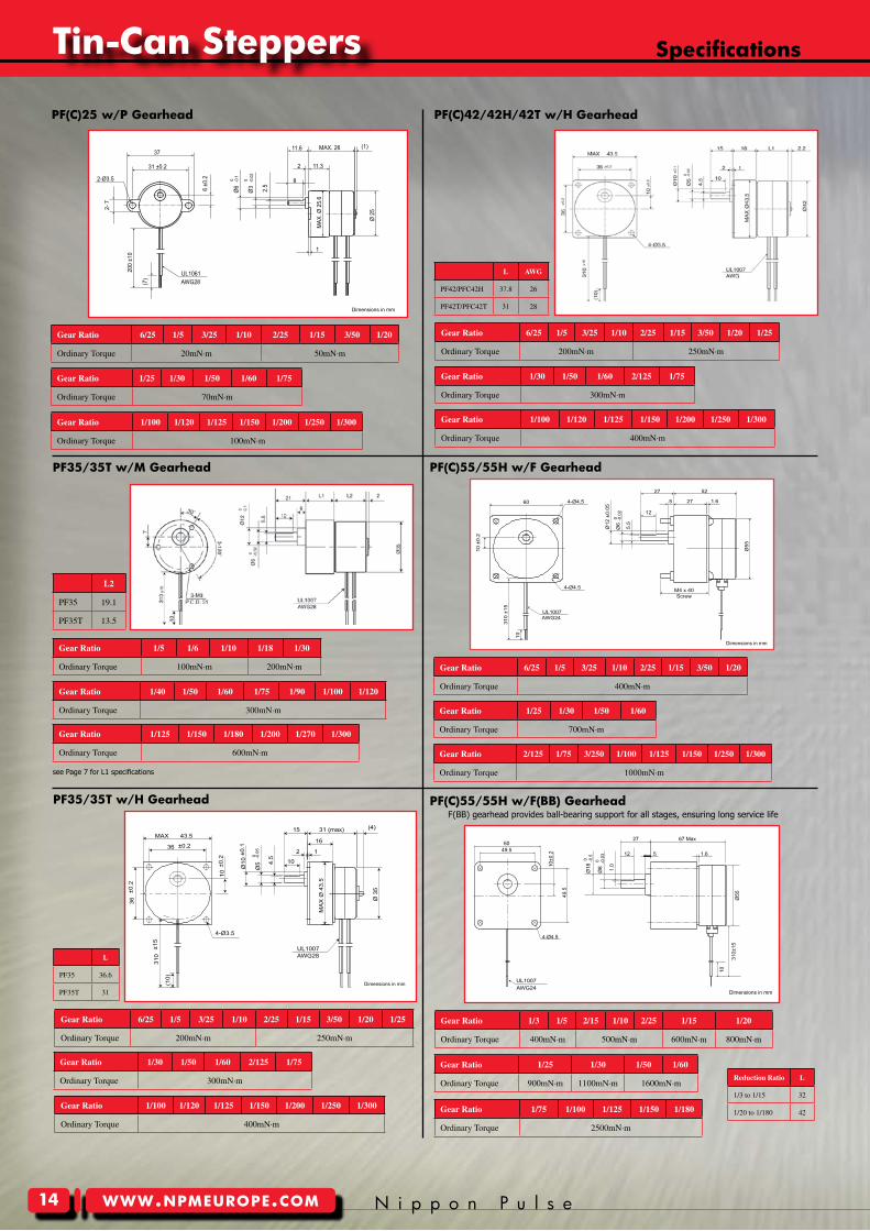
pF(c)25 w/p Gearhead pF(c)42/42H/42T w/H Gearhead
pF35/35T w/m Gearhead pF(c)55/55H w/F Gearhead
pF35/35T w/H Gearhead pF(c)55/55H w/F(BB) GearheadF(BB) gearhead provides ball-bearing support for all stages, ensuring long service life
Reduction Ratio L
1/3to1/15 32
1/20to1/180 42
L2
PF35 19.1
PF35T 13.5
L
PF35 36.6
PF35T 31
Nippon Pulse America, Inc.a subsidiary of Nippon Pulse Motor Co., Ltd.
www.nipponpulse.com1-540-633-1677
PF25 Tin-Can Stepper with Gearhead (P Type)
Dimensions in mm
2-Ø3.5
MAX. 26 (1)11.6
11.32
1
MAX
. Ø 2
5.6
-0.1
0Ø
6
-0.0
2 0
Ø3 2.5
8
Ø 2
5
6 ±
0.2
2- 7
37
31 ±0.2
200
±10
(7) AWG28
UL1061
Nippon Pulse America, Inc.a subsidiary of Nippon Pulse Motor Co., Ltd.
www.nipponpulse.com1-540-633-1677
PFC55 Tin-Can Stepper with Gearhead (F Type)
Dimensions in mm
Ø6
0 -0.0
2
Ø12
±0.
05UL1007AWG24
10 ±
0.2
5.5
310
±15
60
Ø55
12
M4 x 40Screw
10
5227
1.65 27
4-Ø4.5
4-Ø4.5
Nippon Pulse America, Inc.a subsidiary of Nippon Pulse Motor Co., Ltd.
www.nipponpulse.com1-540-633-1677
PF35T Tin-Can Stepper with Gearhead (H Type)
Dimensions in mm
UL1007AWG28
(10)
31 (max)
10
15
136 ±0.2
43.5MAX(4)
16
4-Ø3.5
2
36±0
.2
310
±15
10±0
.2
Ø10
±0.1
Ø5
-0.0
50
4.5
MA
X Ø
43.
5
Ø 3
5
Nippon Pulse America, Inc.a subsidiary of Nippon Pulse Motor Co., Ltd.
www.nipponpulse.com1-540-633-1677
PFC55H Tin-Can Stepper with Gearhead (FB Type)
Dimensions in mm
6049.5
49.5
10±0
.2
310±
15
10
Ø55
1.6
67 Max27
12 5
1.0
4-Ø4.5
Ø8
0 -0.0
3
Ø18
0 -0.5
UL1007AWG24
L AWG
PF42/PFC42H 37.8 26
PF42T/PFC42T 31 28
Specifications
see Page 7 for L1 specifications
Gear Ratio 1/3 1/5 2/15 1/10 2/25 1/15 1/20
OrdinaryTorque 400mN·m 500mN·m 600mN·m 800mN·m
Gear Ratio 1/75 1/100 1/125 1/150 1/180
OrdinaryTorque 2500mN·m
Gear Ratio 1/25 1/30 1/50 1/60
OrdinaryTorque 900mN·m 1100mN·m 1600mN·m
Gear Ratio 6/25 1/5 3/25 1/10 2/25 1/15 3/50 1/20
OrdinaryTorque 400mN·m
Gear Ratio 2/125 1/75 3/250 1/100 1/125 1/150 1/250 1/300
OrdinaryTorque 1000mN·m
Gear Ratio 1/25 1/30 1/50 1/60
OrdinaryTorque 700mN·m
Gear Ratio 6/25 1/5 3/25 1/10 2/25 1/15 3/50 1/20 1/25
OrdinaryTorque 200mN·m 250mN·m
Gear Ratio 1/100 1/120 1/125 1/150 1/200 1/250 1/300
OrdinaryTorque 400mN·m
Gear Ratio 1/30 1/50 1/60 2/125 1/75
OrdinaryTorque 300mN·m
Gear Ratio 1/100 1/120 1/125 1/150 1/200 1/250 1/300
OrdinaryTorque 400mN·m
Gear Ratio 1/30 1/50 1/60 2/125 1/75
OrdinaryTorque 300mN·m
Gear Ratio 6/25 1/5 3/25 1/10 2/25 1/15 3/50 1/20 1/25
OrdinaryTorque 200mN·m 250mN·m
Gear Ratio 1/5 1/6 1/10 1/18 1/30
OrdinaryTorque 100mN·m 200mN·m
Gear Ratio 1/125 1/150 1/180 1/200 1/270 1/300
OrdinaryTorque 600mN·m
Gear Ratio 1/40 1/50 1/60 1/75 1/90 1/100 1/120
OrdinaryTorque 300mN·m
Gear Ratio 6/25 1/5 3/25 1/10 2/25 1/15 3/50 1/20
OrdinaryTorque 20mN·m 50mN·m
Gear Ratio 1/100 1/120 1/125 1/150 1/200 1/250 1/300
OrdinaryTorque 100mN·m
Gear Ratio 1/25 1/30 1/50 1/60 1/75
OrdinaryTorque 70mN·m
Y o u r P a r t n e r I n M o t i o n C o n t r o l www.npmeurope.com
Tin-can Steppers
�5
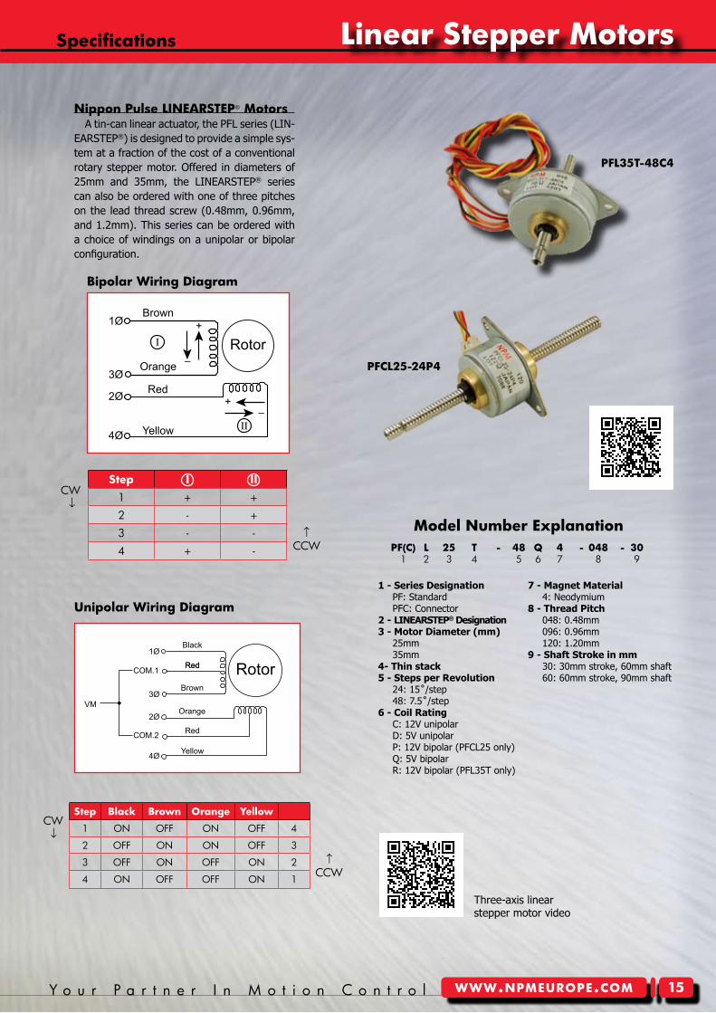
pF(c) L 25 T - 48 Q 4 - 048 - 30 1 2 3 4 5 6 7 8 9
1 - Series Designation PF: Standard PFC: Connector2 - LINEARSTEP® Designation3 - Motor Diameter (mm) 25mm 35mm4- Thin stack5 - Steps per Revolution 24: 15˚/step 48: 7.5˚/step6 - Coil Rating C: 12V unipolar D: 5V unipolar P: 12V bipolar (PFCL25 only) Q: 5V bipolar R: 12V bipolar (PFL35T only)
7 - Magnet Material 4: Neodymium8 - Thread Pitch 048: 0.48mm 096: 0.96mm 120: 1.20mm9 - Shaft Stroke in mm 30: 30mm stroke, 60mm shaft 60: 60mm stroke, 90mm shaft
model number explanation
Step I II1 + +
2 - +
3 - -
4 + -
CW↓
↑CCW
Step Black Brown orange Yellow
1 ON OFF ON OFF 4
2 OFF ON ON OFF 3
3 OFF ON OFF ON 2
4 ON OFF OFF ON 1
CW↓
↑CCW
Bipolar wiring Diagram
unipolar wiring Diagram
pFL35T-48c4
nippon pulse LIneArSTep® motorsA tin-can linear actuator, the PFL series (LIN-
EARSTEP®) is designed to provide a simple sys-tem at a fraction of the cost of a conventional rotary stepper motor. Offered in diameters of 25mm and 35mm, the LINEARSTEP® series can also be ordered with one of three pitches on the lead thread screw (0.48mm, 0.96mm, and 1.2mm). This series can be ordered with a choice of windings on a unipolar or bipolar configuration.
Nippon Pulse America, Inc.a subsidiary of Nippon Pulse Motor Co., Ltd.
www.nipponpulse.com1-540-633-1677
PF/PFC Series Bipolar MotorsWiring Diagram and Rotation Chart
Rotor
Brown
Orange
Red
Yellow4Ø
2Ø
3Ø
1Ø
I
II
+
–
+–
No. 1 + + 2 – + 3 – – 4 + –
I IICW
CW
Nippon Pulse America, Inc.a subsidiary of Nippon Pulse Motor Co., Ltd.
www.nipponpulse.com1-540-633-1677
PF/PFC Series Unipolar MotorsWiring Diagram and Rotation Chart
Rotor
VM
Black
Red
Brown
Orange
Red
Red
Yellow4Ø
2Ø
3Ø
1Ø
COM.1
COM.2
CW
CW
No. BLK BRN ORN YLW No. 1 ON OFF ON OFF 4 2 OFF ON ON OFF 3 3 OFF ON OFF ON 2 4 ON OFF OFF ON 1
Specifications Linear Stepper motors
pFcL25-24p4
Three-axis linear stepper motor video
Tin-can Steppers
�� N i p p o n P u l s ewww.npmeurope.com
unipolar constant Voltage 24x4 Torque curve
Note: Torque curves are for reference only and are not guaranteed.
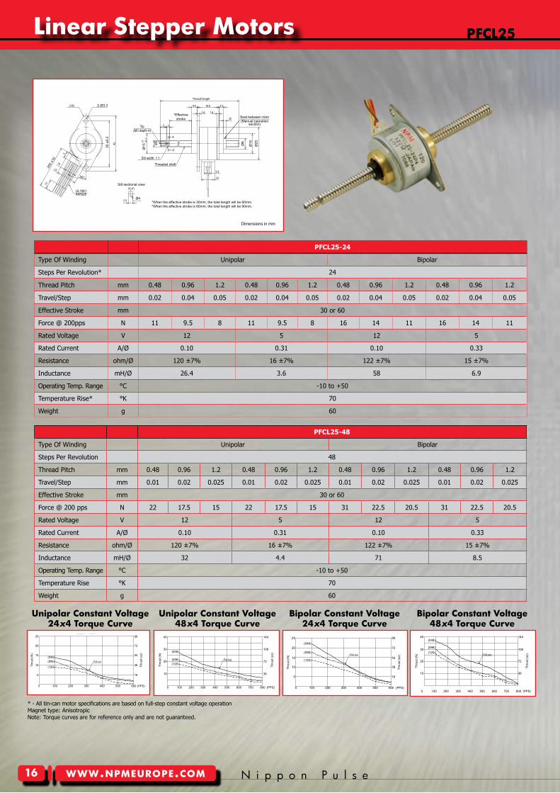
PFCL25-24
Type Of Winding Unipolar Bipolar
Steps Per Revolution* 24
Thread Pitch mm 0.48 0.96 1.2 0.48 0.96 1.2 0.48 0.96 1.2 0.48 0.96 1.2
Travel/Step mm 0.02 0.04 0.05 0.02 0.04 0.05 0.02 0.04 0.05 0.02 0.04 0.05
Effective Stroke mm 30 or 60
Force @ 200pps N 11 9.5 8 11 9.5 8 16 14 11 16 14 11
Rated Voltage V 12 5 12 5
Rated Current A/Ø 0.10 0.31 0.10 0.33
Resistance ohm/Ø 120 ±7% 16 ±7% 122 ±7% 15 ±7%
Inductance mH/Ø 26.4 3.6 58 6.9
Operating Temp. Range °C -10 to +50
Temperature Rise* °K 70
Weight g 60
PFCL25-48
Type Of Winding Unipolar Bipolar
Steps Per Revolution 48
Thread Pitch mm 0.48 0.96 1.2 0.48 0.96 1.2 0.48 0.96 1.2 0.48 0.96 1.2
Travel/Step mm 0.01 0.02 0.025 0.01 0.02 0.025 0.01 0.02 0.025 0.01 0.02 0.025
Effective Stroke mm 30 or 60
Force @ 200 pps N 22 17.5 15 22 17.5 15 31 22.5 20.5 31 22.5 20.5
Rated Voltage V 12 5 12 5
Rated Current A/Ø 0.10 0.31 0.10 0.33
Resistance ohm/Ø 120 ±7% 16 ±7% 122 ±7% 15 ±7%
Inductance mH/Ø 32 4.4 71 8.5
Operating Temp. Range °C -10 to +50
Temperature Rise °K 70
Weight g 60
unipolar constant Voltage48x4 Torque curve
Bipolar constant Voltage24x4 Torque curve
Bipolar constant Voltage48x4 Torque curve
Nippon Pulse America, Inc.a subsidiary of Nippon Pulse Motor Co., Ltd.
www.nipponpulse.com1-540-633-1677
PFCL25-48/PFCL25-24 LINEARSTEP®
Dimensions in mm
2-Ø3.335
±0.
2
*When the effective stroke is 30mm, the total length will be 60mm.*When the effective stroke is 60mm, the total length will be 90mm.
UL1061AWG28
Slit width: 1.1
Threaded shaft
Tip(M3 depth 4)
Seat between rotor(Manual operation
section)
200
±10
30°
*Effectivestroke
Ø15
0 -0.1
Ø5
Ø4
Slit sectional view
Ø8
Ø15
Ø25
pFcL25
Nippon Pulse America, Inc.a subsidiary of Nippon Pulse Motor Co., Ltd.
www.nipponpulse.com1-540-633-1677
PFCL25-48P4 w/ Bipolar Constant VoltageDriver: BCD404B1Power: 12VdcExcitation: Full-step
(048)
(096)(120)
(PPS)0 100 200 300 400 500 600 700 800
Thru
st (o
z)
10
40
30
Thru
st (N
)
20
36
144
108
72
Pull out
Thru
st (o
z)
Nippon Pulse America, Inc.a subsidiary of Nippon Pulse Motor Co., Ltd.
www.nipponpulse.com1-540-633-1677
10
25
20
Thru
st (N
)
(PPS)0 100 200 300 400 500 600
PFCL25-24C4 w/ Unipolar Constant VoltageDriver: PS-2LD-25Power: 12VdcExcitation: Full-step
15
36
5 18
90
72
54(048)(096)
(120)
Pull out
Nippon Pulse America, Inc.a subsidiary of Nippon Pulse Motor Co., Ltd.
www.nipponpulse.com1-540-633-1677
PFCL25-48C4 w/ Unipolar Constant VoltageDriver: PS-2LD-5Power: 12VdcExcitation: Full-step
(PPS)0 100 200 300 400 500 600 700 800
Thru
st (o
z)
10
40
30
Thru
st (N
)
20
36
144
108
72
(048)
(096)(120)
Pull out
Nippon Pulse America, Inc.a subsidiary of Nippon Pulse Motor Co., Ltd.
www.nipponpulse.com1-540-633-1677
(PPS)0 100 200 300 400 500 600
PFCL25-24P4 w/ Bipolar Constant VoltageDriver: BCD404B1Power: 12VdcExcitation: Full-step
(048)
(096)
(120)
Pull out
Thru
st (o
z)
10
25
20
Thru
st (N
)
15
36
5 18
90
72
54
* - All tin-can motor specifications are based on full-step constant voltage operationMagnet type: Anisotropic
Linear Stepper motors
Y o u r P a r t n e r I n M o t i o n C o n t r o l www.npmeurope.com
Tin-can Steppers
�7
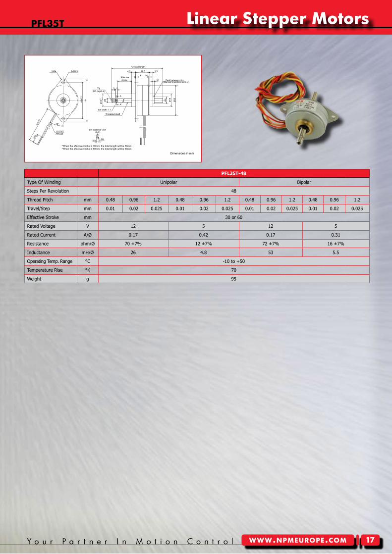
PFL35T-48
Type Of Winding Unipolar Bipolar
Steps Per Revolution 48
Thread Pitch mm 0.48 0.96 1.2 0.48 0.96 1.2 0.48 0.96 1.2 0.48 0.96 1.2
Travel/Step mm 0.01 0.02 0.025 0.01 0.02 0.025 0.01 0.02 0.025 0.01 0.02 0.025
Effective Stroke mm 30 or 60
Rated Voltage V 12 5 12 5
Rated Current A/Ø 0.17 0.42 0.17 0.31
Resistance ohm/Ø 70 ±7% 12 ±7% 72 ±7% 16 ±7%
Inductance mH/Ø 26 4.8 53 5.5
Operating Temp. Range °C -10 to +50
Temperature Rise °K 70
Weight g 95
Nippon Pulse America, Inc.a subsidiary of Nippon Pulse Motor Co., Ltd.
www.nipponpulse.com1-540-633-1677
PFL35T-48 LINEARSTEP®
Dimensions in mm
*When the effective stroke is 30mm, the total length will be 60mm.*When the effective stroke is 60mm, the total length will be 90mm.
30°
Ø5
25
310±1
5
(10)
5042±0
.2
Ø15
0
-0.1
Ø35
Ø15Ø8
(2)
3.516.54.5
1.61.6
UL1007
A'
A
2.9Ø4
2-R4 2-Ø3.5
Seat between rotor(Manual operation section)
AWG28
Slit sectional view
Slit width: 1.1
Threaded shaft
*Effectivestroke
*Overall length
Tip(M3 depth 4)
pFL35T Linear Stepper motors
Tin-can Steppers
�8 N i p p o n P u l s ewww.npmeurope.com
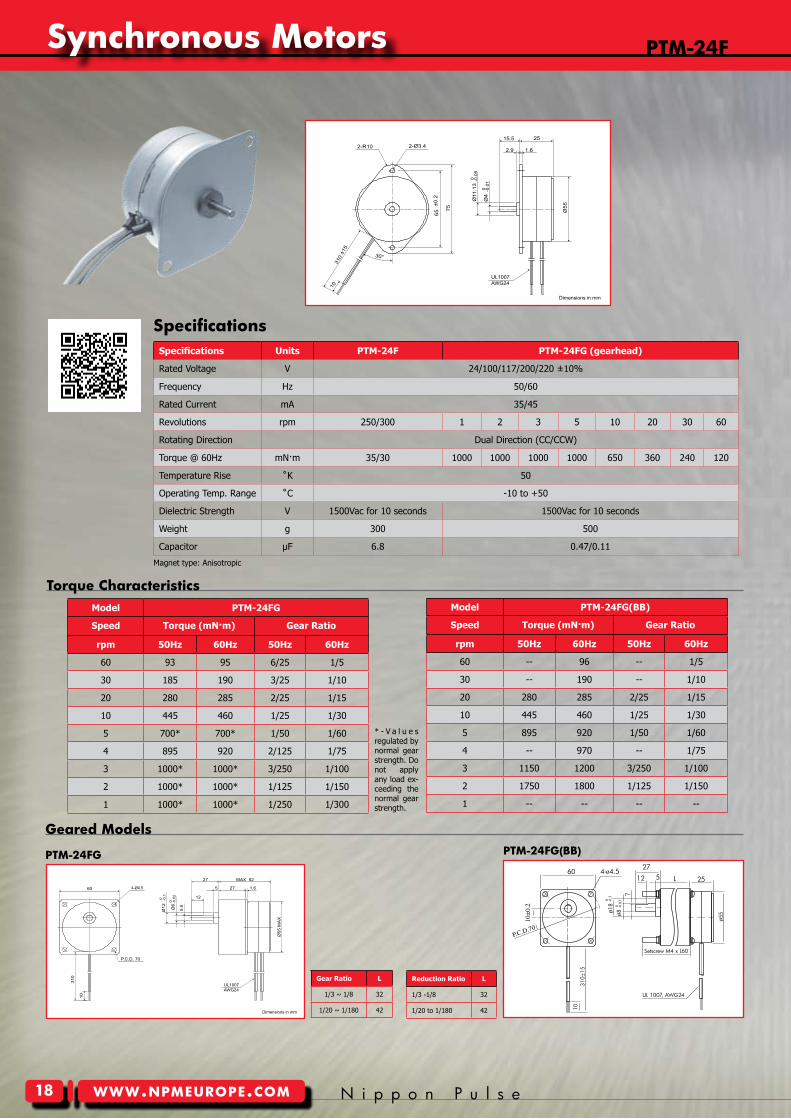
pTm-24F
Geared models
pTm-24FG
Torque characteristicsModel PTM-24FG
Speed Torque (mN·m) Gear Ratio
rpm 50Hz 60Hz 50Hz 60Hz
60 93 95 6/25 1/5
30 185 190 3/25 1/10
20 280 285 2/25 1/15
10 445 460 1/25 1/30
5 700* 700* 1/50 1/60
4 895 920 2/125 1/75
3 1000* 1000* 3/250 1/100
2 1000* 1000* 1/125 1/150
1 1000* 1000* 1/250 1/300
* - V a l u e s regulated by normal gear strength. Do not apply any load ex-ceeding the normal gear strength.
Model PTM-24FG(BB)
Speed Torque (mN·m) Gear Ratio
rpm 50Hz 60Hz 50Hz 60Hz
60 -- 96 -- 1/5
30 -- 190 -- 1/10
20 280 285 2/25 1/15
10 445 460 1/25 1/30
5 895 920 1/50 1/60
4 -- 970 -- 1/75
3 1150 1200 3/250 1/100
2 1750 1800 1/125 1/150
1 -- -- -- --
pTm-24FG(BB)
Gear Ratio L
1/3 ~ 1/8 32
1/20 ~ 1/180 42
Specifications
Reduction Ratio L
1/3 -1/8 32
1/20 to 1/180 42
Nippon Pulse America, Inc.a subsidiary of Nippon Pulse Motor Co., Ltd.
www.nipponpulse.com1-540-633-1677
PTM-24F Synchronous Motor
Dimensions in mm
310
±15
Ø11
.13
0 -0.0
5
1.6
65±0
.2
Ø5575
10
15.5 252-R10 2-Ø3.4
30°
2.9
Ø4
0 -0.0
1
UL1007AWG24
Nippon Pulse America, Inc.a subsidiary of Nippon Pulse Motor Co., Ltd.
www.nipponpulse.com1-540-633-1677
PTM-24FG Synchronous Motor
Dimensions in mm
Ø6
0 -0.0
2
5.5
310
60
Ø55
MA
X
12
10
MAX 5227
1.65 27
P.C.D. 70
Ø12
0 -0.1
4-Ø4.5
UL1007AWG24
60 4-ø4.5 27
12 5 L 25
Setscrew M4 x L60
UL 1007, AWG24
310±
1510
ø55ø1
80 -0
.3
ø80 -0
.03
7
10±
0.2
P.C.D.70
Specifications Units PTM-24F PTM-24FG (gearhead)
Rated Voltage V 24/100/117/200/220 ±10%
Frequency Hz 50/60
Rated Current mA 35/45
Revolutions rpm 250/300 1 2 3 5 10 20 30 60
Rotating Direction Dual Direction (CC/CCW)
Torque @ 60Hz mN·m 35/30 1000 1000 1000 1000 650 360 240 120
Temperature Rise ˚K 50
Operating Temp. Range ˚C -10 to +50
Dielectric Strength V 1500Vac for 10 seconds 1500Vac for 10 seconds
Weight g 300 500
Capacitor µF 6.8 0.47/0.11
Magnet type: Anisotropic
Synchronous motors
Y o u r P a r t n e r I n M o t i o n C o n t r o l www.npmeurope.com
Tin-can Steppers
��
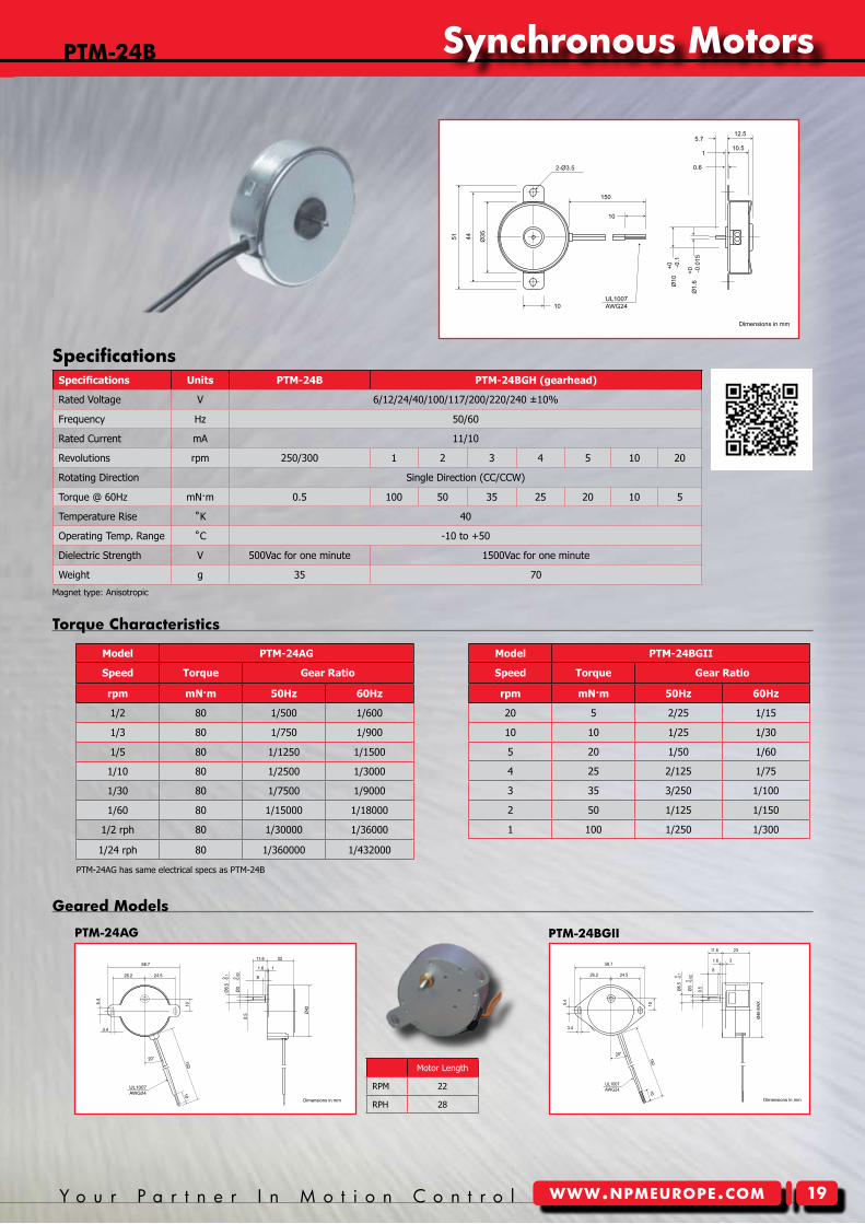
pTm-24B
Model PTM-24AG
Speed Torque Gear Ratio
rpm mN·m 50Hz 60Hz
1/2 80 1/500 1/600
1/3 80 1/750 1/900
1/5 80 1/1250 1/1500
1/10 80 1/2500 1/3000
1/30 80 1/7500 1/9000
1/60 80 1/15000 1/18000
1/2 rph 80 1/30000 1/36000
1/24 rph 80 1/360000 1/432000
Model PTM-24BGII
Speed Torque Gear Ratio
rpm mN·m 50Hz 60Hz
20 5 2/25 1/15
10 10 1/25 1/30
5 20 1/50 1/60
4 25 2/125 1/75
3 35 3/250 1/100
2 50 1/125 1/150
1 100 1/250 1/300
Geared models
pTm-24BGIIpTm-24AG
Torque characteristics
SpecificationsNippon Pulse America, Inc.a subsidiary of Nippon Pulse Motor Co., Ltd.
www.nipponpulse.com1-540-633-1677
PTM-24B Synchronous Motor
Dimensions in mm
12.5
10.55.7
1
0.62-Ø3.5
150
10
10
51 44 Ø35
Ø1.
6+0 -0
.015
Ø10
+0 -0.1
UL1007AWG24
Nippon Pulse America, Inc.a subsidiary of Nippon Pulse Motor Co., Ltd.
www.nipponpulse.com1-540-633-1677
PTM-24AG Synchronous MotorRevolutions: 1/2, 1/3, 1/4, 1/5, 1/6, 1/10, 1/15
Dimensions in mm
1
20°
24.526.2
3.4
58.7
5.4
10
Ø42
11.6 22
1.6
8-0.10
Ø6.
5
-0.0
20
Ø3
0.5
10150
UL1007AWG24
Nippon Pulse America, Inc.a subsidiary of Nippon Pulse Motor Co., Ltd.
www.nipponpulse.com1-540-633-1677
PTM-24BGII Synchronous Motor
Dimensions in mm
3
20°
24.526.2
15010
58.78
-0.0
20
Ø3
-0.10
Ø6.
5
Ø46
MAX
1.6
2311.6
10
3.4
5.4
0.5
UL1007AWG24
Motor Length
RPM 22
RPH 28
Specifications Units PTM-24B PTM-24BGH (gearhead)
Rated Voltage V 6/12/24/40/100/117/200/220/240 ±10%
Frequency Hz 50/60
Rated Current mA 11/10
Revolutions rpm 250/300 1 2 3 4 5 10 20
Rotating Direction Single Direction (CC/CCW)
Torque @ 60Hz mN·m 0.5 100 50 35 25 20 10 5
Temperature Rise ˚K 40
Operating Temp. Range ˚C -10 to +50
Dielectric Strength V 500Vac for one minute 1500Vac for one minute
Weight g 35 70
Magnet type: Anisotropic
Synchronous motors
PTM-24AG has same electrical specs as PTM-24B
Tin-can Steppers
20 N i p p o n P u l s ewww.npmeurope.com
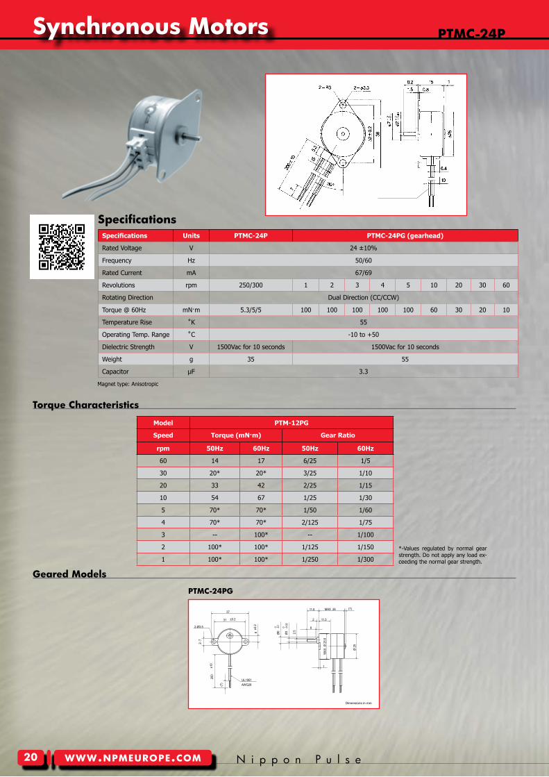
pTmc-24p
Model PTM-12PG
Speed Torque (mN·m) Gear Ratio
rpm 50Hz 60Hz 50Hz 60Hz
60 14 17 6/25 1/5
30 20* 20* 3/25 1/10
20 33 42 2/25 1/15
10 54 67 1/25 1/30
5 70* 70* 1/50 1/60
4 70* 70* 2/125 1/75
3 -- 100* -- 1/100
2 100* 100* 1/125 1/150
1 100* 100* 1/250 1/300
Geared models
pTmc-24pG
Torque characteristics
*-Values regulated by normal gear strength. Do not apply any load ex-ceeding the normal gear strength.
Specifications
Nippon Pulse America, Inc.a subsidiary of Nippon Pulse Motor Co., Ltd.
www.nipponpulse.com1-540-633-1677
PTM-24PG Synchronous Motor
Dimensions in mm
2-Ø3.5
MAX 26 (1)11.6
11.32
1
MAX
. Ø 2
5.6
-0.1
0Ø
6
-0.0
2 0
Ø3 2.5
8
Ø 2
5
±0.
26
2- 7
37
±0.231
±10
200
(7) AWG28
UL1061
Specifications Units PTMC-24P PTMC-24PG (gearhead)
Rated Voltage V 24 ±10%
Frequency Hz 50/60
Rated Current mA 67/69
Revolutions rpm 250/300 1 2 3 4 5 10 20 30 60
Rotating Direction Dual Direction (CC/CCW)
Torque @ 60Hz mN·m 5.3/5/5 100 100 100 100 100 60 30 20 10
Temperature Rise ˚K 55
Operating Temp. Range ˚C -10 to +50
Dielectric Strength V 1500Vac for 10 seconds 1500Vac for 10 seconds
Weight g 35 55
Capacitor µF 3.3
Magnet type: Anisotropic
Synchronous motors
Y o u r P a r t n e r I n M o t i o n C o n t r o l www.npmeurope.com
Tin-can Steppers
2�
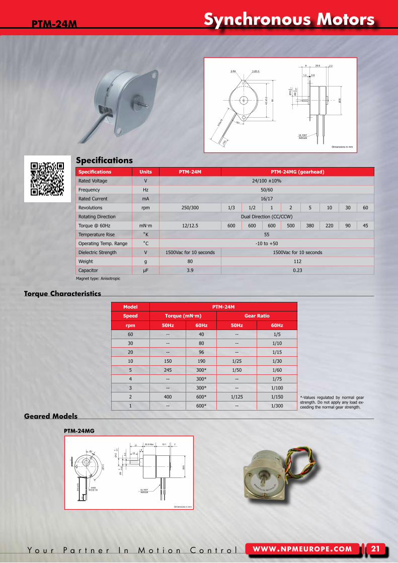
pTm-24m
Geared models
pTm-24mG
Torque characteristics
Model PTM-24M
Speed Torque (mN·m) Gear Ratio
rpm 50Hz 60Hz 50Hz 60Hz
60 -- 40 -- 1/5
30 -- 80 -- 1/10
20 -- 96 -- 1/15
10 150 190 1/25 1/30
5 245 300* 1/50 1/60
4 -- 300* -- 1/75
3 -- 300* -- 1/100
2 400 600* 1/125 1/150
1 -- 600* -- 1/300
*-Values regulated by normal gear strength. Do not apply any load ex-ceeding the normal gear strength.
SpecificationsNippon Pulse America, Inc.a subsidiary of Nippon Pulse Motor Co., Ltd.
www.nipponpulse.com1-540-633-1677
PTM-24M Synchronous Motor
Dimensions in mm
30°
UL1007AWG28
Ø35
310±
15
2.29
1.5 0.8
20.6
(10)
2-R4 2-Ø3.5
42 ±
0.2
50
Ø10
0 -0.1
Ø2
0 -0.0
1
Nippon Pulse America, Inc.a subsidiary of Nippon Pulse Motor Co., Ltd.
www.nipponpulse.com1-540-633-1677
PTM-24MG Synchronous Motor
Dimensions in mm
21
6
5.5 12
2
Ø35
3-M3P.C.D. 31
7
3-120°
30°
310
±15
10
Ø12
0 -0.1
Ø6
0 -0.0
2
26.0 Max 19.1
UL1007AWG28
Specifications Units PTM-24M PTM-24MG (gearhead)
Rated Voltage V 24/100 ±10%
Frequency Hz 50/60
Rated Current mA 16/17
Revolutions rpm 250/300 1/3 1/2 1 2 5 10 30 60
Rotating Direction Dual Direction (CC/CCW)
Torque @ 60Hz mN·m 12/12.5 600 600 600 500 380 220 90 45
Temperature Rise ˚K 55
Operating Temp. Range ˚C -10 to +50
Dielectric Strength V 1500Vac for 10 seconds 1500Vac for 10 seconds
Weight g 80 112
Capacitor µF 3.9 0.23
Magnet type: Anisotropic
Synchronous motors
Tin-can Steppers
22 N i p p o n P u l s ewww.npmeurope.com
pTm-24H
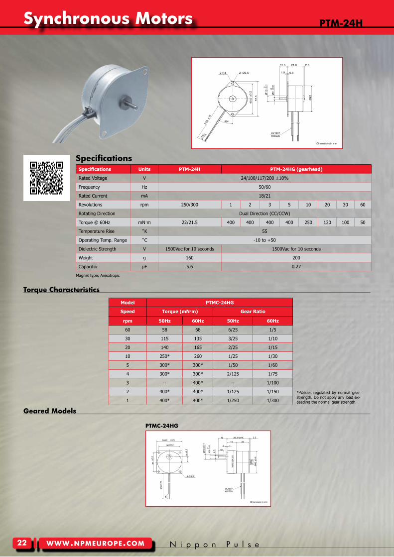
Model PTMC-24HG
Speed Torque (mN·m) Gear Ratio
rpm 50Hz 60Hz 50Hz 60Hz
60 58 68 6/25 1/5
30 115 135 3/25 1/10
20 140 165 2/25 1/15
10 250* 260 1/25 1/30
5 300* 300* 1/50 1/60
4 300* 300* 2/125 1/75
3 -- 400* -- 1/100
2 400* 400* 1/125 1/150
1 400* 400* 1/250 1/300
Geared models
pTmc-24HG
Torque characteristics
*-Values regulated by normal gear strength. Do not apply any load ex-ceeding the normal gear strength.
SpecificationsNippon Pulse America, Inc.a subsidiary of Nippon Pulse Motor Co., Ltd.
www.nipponpulse.com1-540-633-1677
PTM-24H Synchronous Motor
Dimensions in mm
(10)
Ø10
0 -0.1
21.811.5
1.5 0.8
49.5
±0.2
Ø3
0 -0.0
1
310
±15
57.5
Ø42
2-R4 2- Ø3.5
30°
2.2
UL1007AWG26
Nippon Pulse America, Inc.a subsidiary of Nippon Pulse Motor Co., Ltd.
www.nipponpulse.com1-540-633-1677
PTM-24HG Synchronous Motor
Dimensions in mm
38.3 MAX
1
15
36 ±0.216
10
43.5MAX
4-Ø3.5
2
2.2
36±0
.2
310
±15
(8)
10±0
.2
Ø10
±0.1
Ø5
-0.0
50
4.5
Ø42
±0.
5
MA
X Ø
43.5
22
Ø10
UL1007AWG26
Specifications Units PTM-24H PTM-24HG (gearhead)
Rated Voltage V 24/100/117/200 ±10%
Frequency Hz 50/60
Rated Current mA 18/21
Revolutions rpm 250/300 1 2 3 5 10 20 30 60
Rotating Direction Dual Direction (CC/CCW)
Torque @ 60Hz mN·m 22/21.5 400 400 400 400 250 130 100 50
Temperature Rise ˚K 55
Operating Temp. Range ˚C -10 to +50
Dielectric Strength V 1500Vac for 10 seconds 1500Vac for 10 seconds
Weight g 160 200
Capacitor µF 5.6 0.27
Magnet type: Anisotropic
Synchronous motors
Y o u r P a r t n e r I n M o t i o n C o n t r o l www.npmeurope.com
Tin-can Steppers
23
pTm-24T
Geared models
pTm-24TG
Torque characteristics
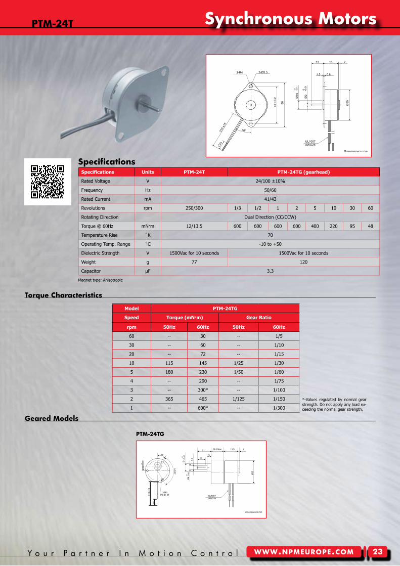
Model PTM-24TG
Speed Torque (mN·m) Gear Ratio
rpm 50Hz 60Hz 50Hz 60Hz
60 -- 30 -- 1/5
30 -- 60 -- 1/10
20 -- 72 -- 1/15
10 115 145 1/25 1/30
5 180 230 1/50 1/60
4 -- 290 -- 1/75
3 -- 300* -- 1/100
2 365 465 1/125 1/150
1 -- 600* -- 1/300
*-Values regulated by normal gear strength. Do not apply any load ex-ceeding the normal gear strength.
Specifications Nippon Pulse America, Inc.a subsidiary of Nippon Pulse Motor Co., Ltd.
www.nipponpulse.com1-540-633-1677
PTM-24T Synchronous Motor
Dimensions in mm
2-R4 2-Ø3.5
310
±15
(10)
30°
42 ±
0.2
50
13 15 2
1.5 0.8
Ø10
-0.10
Ø2
-0.0
10
Ø35
UL1007AWG28
Nippon Pulse America, Inc.a subsidiary of Nippon Pulse Motor Co., Ltd.
www.nipponpulse.com1-540-633-1677
PTM-24TG Synchronous Motor
Dimensions in mm
21
6
5.5 12
2
Ø35
3-M3P.C.D. 31
7
3-120°
30°
310
±15
10
Ø12
0 -0.1
Ø6
0 -0.0
2
26.0 Max 13.5
UL1007AWG28
Specifications Units PTM-24T PTM-24TG (gearhead)
Rated Voltage V 24/100 ±10%
Frequency Hz 50/60
Rated Current mA 41/43
Revolutions rpm 250/300 1/3 1/2 1 2 5 10 30 60
Rotating Direction Dual Direction (CC/CCW)
Torque @ 60Hz mN·m 12/13.5 600 600 600 600 400 220 95 48
Temperature Rise ˚K 70
Operating Temp. Range ˚C -10 to +50
Dielectric Strength V 1500Vac for 10 seconds 1500Vac for 10 seconds
Weight g 77 120
Capacitor µF 3.3
Magnet type: Anisotropic
Synchronous motors
Tin-can Steppers
24 N i p p o n P u l s ewww.npmeurope.com
pTmc-24S2
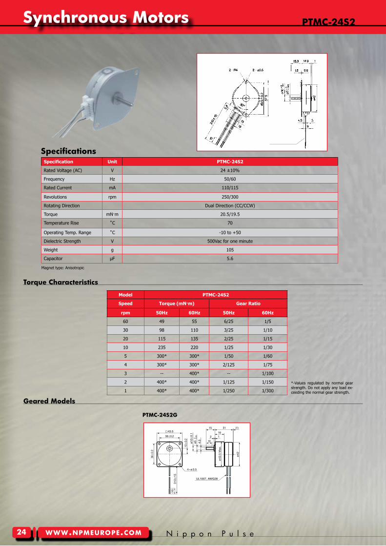
Specification Unit PTMC-24S2
Rated Voltage (AC) V 24 ±10%
Frequency Hz 50/60
Rated Current mA 110/115
Revolutions rpm 250/300
Rotating Direction Dual Direction (CC/CCW)
Torque mN·m 20.5/19.5
Temperature Rise ˚C 70
Operating Temp. Range ˚C -10 to +50
Dielectric Strength V 500Vac for one minute
Weight g 105
Capacitor µF 5.6
Model PTMC-24S2
Speed Torque (mN·m) Gear Ratio
rpm 50Hz 60Hz 50Hz 60Hz
60 49 55 6/25 1/5
30 98 110 3/25 1/10
20 115 135 2/25 1/15
10 235 220 1/25 1/30
5 300* 300* 1/50 1/60
4 300* 300* 2/125 1/75
3 -- 400* -- 1/100
2 400* 400* 1/125 1/150
1 400* 400* 1/250 1/300
Geared models
pTmc-24S2G
Torque characteristics
*-Values regulated by normal gear strength. Do not apply any load ex-ceeding the normal gear strength.
Specifications
Magnet type: Anisotropic
Synchronous motors
Y o u r P a r t n e r I n M o t i o n C o n t r o l www.npmeurope.com
Tin-can Steppers
25
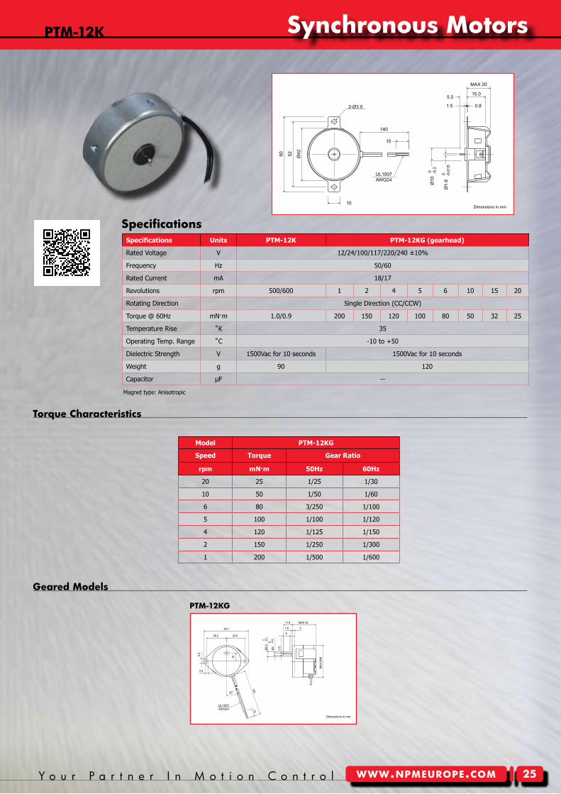
Model PTM-12KG
Speed Torque Gear Ratio
rpm mN·m 50Hz 60Hz
20 25 1/25 1/30
10 50 1/50 1/60
6 80 3/250 1/100
5 100 1/100 1/120
4 120 1/125 1/150
2 150 1/250 1/300
1 200 1/500 1/600
Geared models
pTm-�2KG
Torque characteristics
Specifications
Nippon Pulse America, Inc.a subsidiary of Nippon Pulse Motor Co., Ltd.
www.nipponpulse.com1-540-633-1677
PTM-12EG / PTM-12KG Synchronous Motor
Dimensions in mm
20°
24.526.2
10
MAX
Ø46
MAX 3411.6
31.6
-0.10
Ø6.
5
-0.0
20
8
14010
3.4
5.4
58.7
Ø3
0.5
UL1007AWG24
Nippon Pulse America, Inc.a subsidiary of Nippon Pulse Motor Co., Ltd.
www.nipponpulse.com1-540-633-1677
PTM-12E / PTM-12K Synchronous Motor
Dimensions in mm
MAX 20
15.05.5
1.5 0.8
Ø10
2-Ø3.5
140
10
10
60 52 Ø42
0 -0.2
Ø1.
6 0 -0
.015
UL1007AWG24
Specifications Units PTM-12K PTM-12KG (gearhead)
Rated Voltage V 12/24/100/117/220/240 ±10%
Frequency Hz 50/60
Rated Current mA 18/17
Revolutions rpm 500/600 1 2 4 5 6 10 15 20
Rotating Direction Single Direction (CC/CCW)
Torque @ 60Hz mN·m 1.0/0.9 200 150 120 100 80 50 32 25
Temperature Rise ˚K 35
Operating Temp. Range ˚C -10 to +50
Dielectric Strength V 1500Vac for 10 seconds 1500Vac for 10 seconds
Weight g 90 120
Capacitor µF --
pTm-�2K
Magnet type: Anisotropic
Synchronous motors
Tin-can Steppers
2� N i p p o n P u l s ewww.npmeurope.com
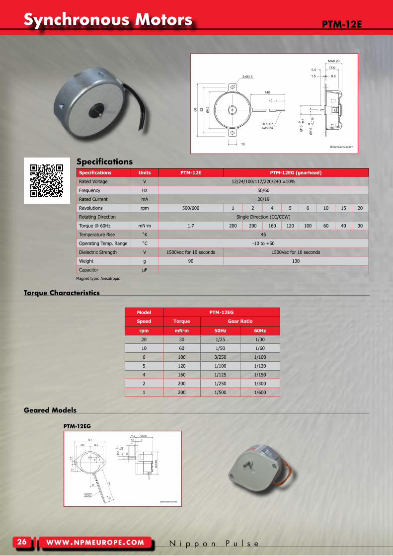
pTm-�2e
Model PTM-12EG
Speed Torque Gear Ratio
rpm mN·m 50Hz 60Hz
20 30 1/25 1/30
10 60 1/50 1/60
6 100 3/250 1/100
5 120 1/100 1/120
4 160 1/125 1/150
2 200 1/250 1/300
1 200 1/500 1/600
Geared models
pTm-�2eG
Torque characteristics
SpecificationsNippon Pulse America, Inc.a subsidiary of Nippon Pulse Motor Co., Ltd.
www.nipponpulse.com1-540-633-1677
PTM-12E / PTM-12K Synchronous Motor
Dimensions in mm
MAX 20
15.05.5
1.5 0.8
Ø10
2-Ø3.5
140
10
10
60 52 Ø42
0 -0.2
Ø1.
6 0 -0
.015
UL1007AWG24
Nippon Pulse America, Inc.a subsidiary of Nippon Pulse Motor Co., Ltd.
www.nipponpulse.com1-540-633-1677
PTM-12EG / PTM-12KG Synchronous Motor
Dimensions in mm
20°
24.526.2
10
MAX
Ø46
MAX 3411.6
31.6
-0.10
Ø6.
5
-0.0
20
8
14010
3.4
5.4
58.7
Ø3
0.5
UL1007AWG24
Specifications Units PTM-12E PTM-12EG (gearhead)
Rated Voltage V 12/24/100/117/220/240 ±10%
Frequency Hz 50/60
Rated Current mA 20/19
Revolutions rpm 500/600 1 2 4 5 6 10 15 20
Rotating Direction Single Direction (CC/CCW)
Torque @ 60Hz mN·m 1.7 200 200 160 120 100 60 40 30
Temperature Rise ˚K 45
Operating Temp. Range ˚C -10 to +50
Dielectric Strength V 1500Vac for 10 seconds 1500Vac for 10 seconds
Weight g 90 130
Capacitor µF --
Magnet type: Anisotropic
Synchronous motors
Y o u r P a r t n e r I n M o t i o n C o n t r o l www.npmeurope.com
Tin-can Steppers
27
Name
1 Motor A
2 Motor /A
3 Motor B
4 Motor /B
5 GND
6 Power (12-24V)
J1 Connector/Power, Motor
Name
1 Opto-supply (+5V)
2 Pulse
3 Direction
4 Enable
5 Reset
J2 Connector Signal
Mount on a Hybrid Motor
Use with MCH-5
Specifications
Drive Method Microstep Bipolar Chopping Drive
Microstep Full, 1/2, 1/4, 1/16
Current 1.2A/phase (peak)
Power Input 12 to 30Vdc
Signal Pulse/Dir/Enable/Reset (Isolated)
Function Auto-current-down, Mixed Decay
npAD�0BF - microstepping DriveFeatures:• 16 microsteps• Wide range of input power• Max. 1.2A/phase (peak)• Pulse/Dir input• Easy connection by block terminals
PPCI series (PPCI7443) is an ad-vanced PCI-bus format 4-axis mo-tion control board that controls stepper motors or/and servomo-tors. The PPCI7443 incorporates a PCL6045 series motion control
chip as part of its compact design, and it comes with user-friendly software that incorporates MS-DOS, C/C++ program-ming library; Windows® 95/98/ME/NT/2000 DLL; and a test monitor. The software allows for easy set-up and supports up to a maximum of 12 PPCI7443 cards, allowing for operation of up to 48 axes.
ppcI Series npmc SeriesNPMC series is an advanced PC/104-bus
format multi-axes motion control board that controls stepper motors or/and ser-vomotors. The PCL5023 motion control chip is used as key component for 2-axes (NPMC5023-2104) controller boards, while
the PCL6045 motion control chip is used as key component for 4-axes (NPMC6045A-4104) controller boards.
Nippon Pulse Motion Checkers are palm-sized controllers with a built-in in-tegrated driver circuit for 2-phase stepper motors. Both Motion Checker-3 and Motion Checker-5 series run unipolar and bipolar-winding stepper motors. MCH-5 series has a pulse/direction output signal enabling its use as a standalone controller to connect to any driver board.
The Motion Checker series can be used for quick stepper motor evaluation, stepper motor life testing, and educational training.
motion checker 5
J2J1J1
31.0
31.0
43.418.5
Board Level controllers
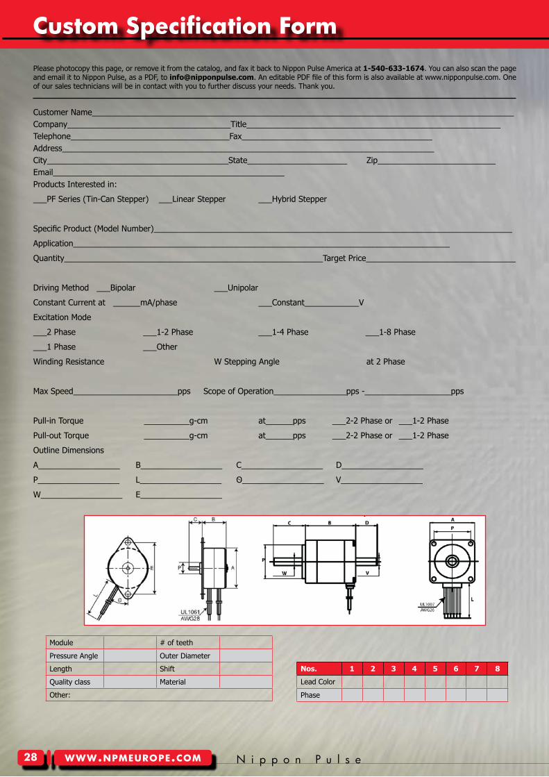
Tin-can Steppers
28 N i p p o n P u l s ewww.npmeurope.com
Custom Specification Form
Customer Name_____________________________________________________________________________________________Company____________________________________Title________________________________________________________ Telephone___________________________________Fax__________________________________________ Address__________________________________________________________________________________City________________________________________State______________________ Zip__________________________ Email___________________________________________________ Products Interested in:
___PF Series (Tin-Can Stepper) ___Linear Stepper ___Hybrid Stepper
Specific Product (Model Number)_______________________________________________________________________________
Application___________________________________________________________________________________
Quantity_________________________________________________________Target Price_________________________________
Driving Method ___Bipolar ___Unipolar
Constant Current at ______mA/phase ___Constant____________V
Excitation Mode
___2 Phase ___1-2 Phase ___1-4 Phase ___1-8 Phase
___1 Phase ___Other
Winding Resistance W Stepping Angle at 2 Phase
Max Speed_______________________pps Scope of Operation________________pps -___________________pps
Pull-in Torque __________g-cm at______pps ___2-2 Phase or ___1-2 Phase
Pull-out Torque __________g-cm at______pps ___2-2 Phase or ___1-2 Phase
Outline Dimensions
A__________________ B__________________ C__________________ D__________________
P__________________ L__________________ O__________________ V__________________
W__________________ E__________________
Nos. 1 2 3 4 5 6 7 8
Lead Color
Phase
Module # of teeth
Pressure Angle Outer Diameter
Length Shift
Quality class Material
Other:
Please photocopy this page, or remove it from the catalog, and fax it back to Nippon Pulse America at 1-540-633-1674. You can also scan the page and email it to Nippon Pulse, as a PDF, to [email protected]. An editable PDF file of this form is also available at www.nipponpulse.com. One of our sales technicians will be in contact with you to further discuss your needs. Thank you.
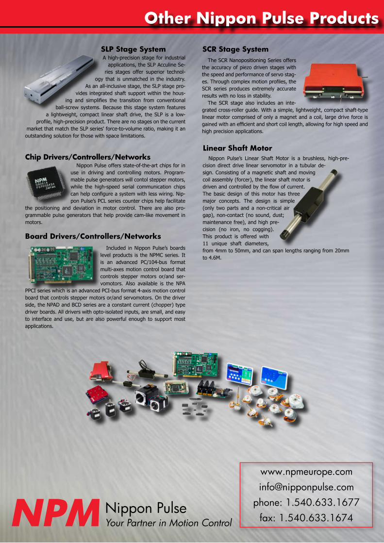
other nippon pulse products
Nippon Pulse’s Linear Shaft Motor is a brushless, high-pre-cision direct drive linear servomotor in a tubular de-sign. Consisting of a magnetic shaft and moving coil assembly (forcer), the linear shaft motor is driven and controlled by the flow of current. The basic design of this motor has three major concepts. The design is simple (only two parts and a non-critical air gap), non-contact (no sound, dust; maintenance free), and high pre-cision (no iron, no cogging). This product is offered with 11 unique shaft diameters, from 4mm to 50mm, and can span lengths ranging from 20mm to 4.6M.
A high-precision stage for industrial applications, the SLP Acculine Se-
ries stages offer superior technol-ogy that is unmatched in the industry.
As an all-inclusive stage, the SLP stage pro-vides integrated shaft support within the hous-
ing and simplifies the transition from conventional ball-screw systems. Because this stage system features
a lightweight, compact linear shaft drive, the SLP is a low-profile, high-precision product. There are no stages on the current
market that match the SLP series' force-to-volume ratio, making it an outstanding solution for those with space limitations.
The SCR Nanopositioning Series offers the accuracy of piezo driven stages with the speed and performance of servo stag-es. Through complex motion profiles, the SCR series produces extremely accurate results with no loss in stability.
The SCR stage also includes an inte-grated cross-roller guide. With a simple, lightweight, compact shaft-type linear motor comprised of only a magnet and a coil, large drive force is gained with an efficient and short coil length, allowing for high speed and high precision applications.
Scr Stage System
Linear Shaft motor
Board Drivers/controllers/networks
chip Drivers/controllers/networks
SLp Stage System
Nippon Pulse offers state-of-the-art chips for in use in driving and controlling motors. Program-mable pulse generators will contol stepper motors, while the high-speed serial communication chips can help configure a system with less wiring. Nip-pon Pulse’s PCL series counter chips help facilitate
the positioning and deviation in motor control. There are also pro-grammable pulse generators that help provide cam-like movement in motors.
Included in Nippon Pulse’s boards level products is the NPMC series. It is an advanced PC/104-bus format multi-axes motion control board that controls stepper motors or/and ser-vomotors. Also available is the NPA
PPCI series which is an advanced PCI-bus format 4-axis motion control board that controls stepper motors or/and servomotors. On the driver side, the NPAD and BCD series are a constant current (chopper) type driver boards. All drivers with opto-isolated inputs, are small, and easy to interface and use, but are also powerful enough to support most applications.
Nippon Pulsenpm Your Partner in Motion Control
phone: 1.540.633.1677fax: 1.540.633.1674
4 Corporate DriveRadford, VA 24141 USAphone: 1-540-633-1677 … fax: 1-540-633-1674www.npmeurope.com … [email protected]
European Stepper Motor Catalog | e: 7.13.11 | 201012-1KCopyright 2011 | Nippon Pulse | All Rights Reserved
The nippon pulseAdvantage
For nearly sixty years, Nippon Pulse has built state-of-of-the-art products based on a solid foundation of advancing technology and thorough product research.
Nippon Pulse America, Inc. (NPA) faithfully provides these high-quality products to a wide range of industries in North and South America, as well as Europe. Nippon Pulse has established itself as a leader in stepper motor,
driver, and controller technology while introducing innovative products such as the Linear Shaft Motor and MotionNet. At Nippon Pulse, we believe that by bringing products to market which not only meet customers’
requirements, but actually impress them, we contribute to the progression of technology and its positive impact on our society. We pride ourselves on the reputation of our high-quality products that provide that impact. Nippon Pulse’s mission is to faithfully create new products sought by its customers and to contribute to the development
of society from a global viewpoint.
Nippon Pulse has representatives throughout North and South America and Europe to directly assist customers. Limited quantities of stock on standard motors and electronics are available to allow faster response to customer needs. In addition, Nippon Pulse America has a model shop in its headquarters for quick turnaround on custom
prototypes and special orders. A wholly owned subsidiary of Nippon Pulse Motor Co., Ltd., Nippon Pulse America is headquartered in Radford, Va.
When you choose a Nippon Pulse motor, driver, controller, network or stage, you’re doing more than just buying a quality product. You’re benefitting from what we call the Nippon Pulse Advantage. This includes superior prototyping, complete system engineering, proper compliance and certification according to international
guidelines, and exceptional tailoring to your needs. It also includes unmatched support.
Our biggest asset at Nippon Pulse is our people, both our employees and our customers. We ensure that we have the best people working for us so that we build loyalty among those buying from us. It’s an advantage you won’t
Nippon Pulse Representative Information
npm