Gas Turbine Performances Improvement using Steam Injection ...

Steam Injection Humidifiers DDS
for existing steam nets
Manual

Page 2
Warning, Hazardous Voltage: All work to be performed by trained personnel only.
All electrical installation and servicing of the electrical components of this unit to be
performed by qualified electricians only. Disconnect power supply before installation
and servicing!
Copyright HygroMatik GmbH
DDS January 2011
Information in this manual is subject to change or alterate without prior notice.

Page 3
1. Introduction ....................................................................................................................... 5
1.1 Directions for Use .............................................................................................................. 5
1.2 TypographicsTypographic Distinctions .............................................................................. 5
2. Safety Instructions ............................................................................................................ 6
2.1 Operational Safety Instructions ......................................................................................... 6
2.2 Disposal after de-installation ............................................................................................. 7
3. Transport ............................................................................................................................ 8
3.1 Packing .............................................................................................................................. 8
3.2 Temporary storage ............................................................................................................ 8
3.3 Checking for correct and complete delivery ...................................................................... 8
4. Function and Assembly .................................................................................................... 9
4.1 Function ............................................................................................................................. 9
5. Strainer ............................................................................................................................... 10
5.1 Technical Data .................................................................................................................. 10
6. Separator ............................................................................................................................ 11
6.1 Function ............................................................................................................................. 11
6.2 Technical Data .................................................................................................................. 11
7. Control Valve and Actuator .............................................................................................. 12
7.1 Control Valve ..................................................................................................................... 12
7.2 Actuator ............................................................................................................................. 13
8. Start-up safety switch ....................................................................................................... 14
9. Steam Lances .................................................................................................................... 15
9.1 Technical Data ................................................................................................................. 16
9.2 Number of steam lances ................................................................................................... 16
10. Pressure Gauge Station .................................................................................................. 18
11. Ball Float Steam Trap ..................................................................................................... 19
11.1 Function ........................................................................................................................... 19
11.2 Technical Data ................................................................................................................ 20
11.2.1 KS-Condensate Drain for DDS Type A ....................................................................... 20
11.2.2 KS-Condensate Drain for DDS Type C ........................................................................ 20
12. Thermostatic Capsule Steam Trap ................................................................................ 21
12.1 Function ........................................................................................................................... 21
12.2 Technical Data ................................................................................................................ 22
13. Humidification Output ..................................................................................................... 23
13.1 Output Graphs ................................................................................................................. 23
13.2 Determining the control valve Kvs-Value ....................................................................... 23
13.3 Separator Type 20 with one steam lance ....................................................................... 25
13.4 Separator Type 20 with multiple steam lances ............................................................... 26
13.5 Separator Type 40 with one steam lance ....................................................................... 27
13.6 Separator Type 40 with multiple steam lances .............................................................. 28
14. Graph for Determing Absorption Distance ................................................................... 29

Page 4
15. Installation ....................................................................................................................... 30
15.1 Attaching steam pipes ..................................................................................................... 31
15.2 Electrical Installation ........................................................................................................ 32
15.3 Separators ....................................................................................................................... 33
15.4 Control Valve and Actuator ............................................................................................. 34
15.5 Pneumatic Start-up safety feature ................................................................................... 35
15.6 Steam Lances ................................................................................................................. 36
15.7 Installation Examples ...................................................................................................... 39
15.8 Steam Lance Heating System ......................................................................................... 41
15.9 Check List ........................................................................................................................ 42
16. Initial Operation ............................................................................................................... 43
17. Maintenance ..................................................................................................................... 45
17.1 Maintenance work ........................................................................................................... 45
17.2 Strainer ............................................................................................................................ 45
17.3 Ball float condensate drain .............................................................................................. 46
17.4 Thermostatic Capsule Steam trap type MST21 ............................................................ 47
18. Malfunctions .................................................................................................................... 48
19. Dismantling ...................................................................................................................... 50
20. Steam Injection System dimensions and Installation Schematic. .............................. 51
21. Spare Parts ...................................................................................................................... 52
22. Fax Form - Order for spare parts ................................................................................... 54

Page 5
1. Introduction
Dear Customer,
HygroMatik steam Injection humidifiers, produce dry steam for
humidification in A/C ducting and other applications.
Your steam injection humidifier comprises steam separators,
steam lances, steam trap, control valve and actuator. It is
extremely economical, safe in operation and easy to use.
In order to operate the HygroMatik steam injection humidifier in
a safe, orderly and economical fashion please take the time to
read this operating manual.
Please use the steam injection humidifier in a proper condition,
use only as it is intended and with regard to all the safety and
hazard indications and notes in this manual.
If you have any queries at all please get in touch as follows:
Tel.: +49-(0)4193/ 895-0 (Switchboard)
Tel.: +49-(0)4193/ 895-293 (Technical Hotline)
Fax: +49-(0)4193/ 895-33
E-Mail: [email protected]
1.1 Directions for Use
Your HygroMatik steam injection humidifier makes use of exist-
ing live steam for humidification purposes.
Proper usage involves strict adherence to our installation, de-
and re-installation, commissioning, operation and maintenance
requirements as well as proper disposal procedures.
Only qualified and authorised personnel may operate or service
the unit. Persons having to do with transport or any work on and
with the unit must previously have read and understood the rele-
vant parts of the manual, especially the section on safety
requirements. Additionally, the operator must inform such per-
sonnel about any possible hazards. Please place an example of
the operating instructionsl, clearly visible, at or near the installed
unit.
1.2 TypographicsTypographic Distinctions
• preceded by a bullet: general specifications.
» preceded by an arrow: Procedures for servicing or
maintenance which should or must be performed in the
indicated order.
Installation step which must be checked off.

Page 6
2. Safety Instructions
Overview
Adherence to these safety instructions are required by law. They
are there for your safety and for the prevention of industrial acci-
dents .
Warnings and Safety symbols
The following safety symbols indicate texts that contain warnings
concerning possible hazards. Please familiarise yourself with
these symbols.
Warning: Ignoring this warning may result in bodily injury and/or
damage to the unit.
Warning, High Voltage: Dangerous electrical voltage. Ignoring
this warning may cause serious bodily injury.
Note: Materials or other items that must be disposed of accord-
ing to the law.
Note: Indicates explanations or cross references to other parts
of the manual.
2.1 Operational Safety Instructions
Overview
In the case of malfunction shut off steam supply and make sure
it cannot be opened by unauthorised personnel. Correct mal-
function immediately.
After repair, operational safety must be checked out by autho-
rised personnel.
Use only original spare parts.
National laws also fully apply to the use of this steam injection
humidifier.
Accident prevention laws
Please comply with accident prevention laws:
See UVV Electical Appliances and associated units (VBG 4).
This can prevent injury to yourself and others.
Operating the Steam Injection Humidifier
Please do not do any work in such a way as to endanger the
safe operation of the unit.
Check all safety and monitoring elements regularly for correct
functioning.
Do not remove disable or de-install any safety-relevant items.

Page 7
Installation, de-installation, servicing and repair
Steam injection humidifier parts on which maintenance or repair
work is to be done must be disconnected from voltage and the
steam supply shut off. Installation of any additional parts is
allowed only after written permission from the manufacturer.
Electrical
Only qualified electricians may carry out electrical work on the
unit.
Remove voltage from any components being worked on. If the
energy supply is malfunctioning switch off the unit immediately .
After electrical work or repair is carried out all safety elements
must be tested for proper functioning.
Attention: Use only steam with a minimum pressure of 0,5 bar
and a maximum pressure of 4 bar at the entry point of the steam
injection humidifier.
Attention: Steam pipes are hot and care must be taken accord-
ingly.
Attention: use only steam without chemical additives.
Attention: Steam supply must be dimensioned so that the
steam velocity does not exceed 25 m/s.
Attention: The control valves are not stop valves. They have
been optimised to control the necessary steam supply. They are
metal to metal sealed according to IEC 534-4 Class IV and can,
therefore, show a leakage of 0.01 % when supplied. We recom-
mend the use of a stop valve in order to ensure that the steam
supply is completely shut off.
Attention: There may be impurities in the steam supply. In order
to prevent valve damage there must be a filter installed with a
pore diameter of <0.16 mm.
Attention: In order to maintain a continuous and constant
humidification the humidity sensors should not be fitted in the
supply duct.
2.2 Disposal after de-installation
Note: The operator is responsible for the lawful disposal of the
steam injection humidifier components.

Page 8
3. Transport
Overview
Note: If there is any transport damage and/or missing items
please get in touch with the transport company or supplier
immediately.
3.1 Packing
Note: Please observe the pictures on the packing.
The kind of packing used is dependent upon the type of unit sup-
plied. .
Accessories, such as steam traps, that can be part of the com-
plete order are packed separately.
If the control valve is part of the delivery it will be delivered
already installed on the steam separator. Additional screw fit-
tings are packaged separately.
Steam lances are delivered in special protective wrappings.
3.2 Temporary storage
The steam injection humidifier must be stored in a dry and frost
free area.
3.3 Checking for correct and complete delivery
On delivery please check that:
• the delivery corresponds to the order and delivery note.
• The data on the manufacturer‘s name plate corresponds to
the order and supply note
• All delivered components are in a proper condition
Note: Take care when transporting the steam injection humidi-
fier in order to prevent damage especially when loading and
unloading.
Take note of time limits for reporting damaged deliveries and
damage assessment. Here is a list of time limits :
Transport organisation after delivery
Post latest 24 hours.
Rail latest 7 days
Rail and road latest 4 days
Package services immediate

Page 9
4. Function and Assembly
The HygroMatik Steam Injection Humidifier comprises 4 basic
elements:
• Separator
• Control valve with or without control operation
• Steam Lances
• Additional materials
There is a stainless steel version Type A
and a mixed material version Type C
4.1 Function
Steam flows through a dirt particle trap (1) over the Separator
interface (2) into the Separator (3). The separator separates
condensation from the steam.
Condensation is drained using the float controlled condensa-
tion drainage. The Start-up security feature (5) measures the
temperature at the condensation return. Operation switch (11)
is activated when the switch temperature has reached approx.
80°C.
Now the main portion of the steam flows through the control
valve (7). The amount of steam is regulated over the operation
switch (11).
Steam lances (n) (8) are flanged or screwed onto the valve exit
side.
Dried steam is blown out through the specially formed nozzles
(9) that take the dried steam from the pipe centre. The nozzles
are press-fitted into the steam lances.
The steam lance heating system is fed over connection (6) on
the separator. Alternatively there is the possibility to seal the
separator connection and operate the steam lance heating sys-
tem from a separate steam reservoir. A thermic Capsule Con-
densation Drain (10) ensures that condensation in the steam
lance heating system is drained off.
HygroMatik DDS Type A
*all stainless steel contruction
HygroMatik DDS Type C
*dirt trap, KS-Condensation drain and Valve as castings

Page 10
5. Strainer
There should be a strainer installed in the steam supply line
directly in front of every separator. Only if this is done can it be
guaranteed that there are no foreign particles in the humidifier
unit.
Valve cone and valve face in both the control valve and steam
trap are sensitive to fouling. Dirt particles between the face and
the cone prevent normal closure and have a corrosive effect. .
Function
Steam flows through the inlet in the cylindrical version (type C)
or the conical strainer (type A) and through the holes to the exit.
Foreign matter is retained by the strainer.
5.1 Technical Data
Strainer 12.1 for type C Vers .20 Vers. 40
Nominal pressure setting PN 25
Female thread 3/4“ 1 1/2“
Weight 0,60 kg 2,4 kg
Dimensions A
B
C
D
93mm
65mm
110mm
38mm
153mm
115mm
190mm
62mm
Materials
Housing
Filter fitting
Seal
Coarse strainer
GGG40
GGG40
Graphite, reinforced
with nickel
Stainless steel 316L
pore size, coarse strainer 0,16mm
Strainer type A *installed in the entry flange
Strainer type C
*Principle only; delivery in screwed version

Page 11
6. Separator
The stainless steel separator is the essential component for
moisture separation. The separator is available in versions 20
and 40. The separator size is dependent upon the desired
steam output and available steam pressure.
6.1 Function
Steam flows through the pipe union (1) into the separator.
Steam and condensate are separated by the joint action of the
inlet pipe (2) and the spiral-shaped flow system.
The aerosole droplets present in the steam are thrown against
the outer wall by centrifugal force which separates them from the
steam phase. The droplets are conveyed through the drain (3)
into the condensate return. This prevents droplets from being
transported by the steam.
Steam is conveyed into the upper part of the separator chamber
via a supply pipe (4) or directly to the valve.
A certain amount of steam flows through the connector (5) and
feeds the steam lance heating system.
The bulk of the steam exits the separator through the outlet
connection (6) and flows through the control valve.
6.2 Technical Data
Separator DDS20 DDS40
Type A Type C Type
A
Type
C
Thread connections B
C
D
1/4“
1/2“
DN25
1/4“
1/2“
3/4“
1/4“
1/2“
DN40
1/4"
1"
1 1/2"
Weight [kg] 3,6 1,46 7,3 3,70
Dimensions [mm] c
d
e
f
45
-
235
89
62
43
208
105
60
-
340
122
79
70
316
152
Materials Housing
internal
CrNiMo
Steel
1.4301
1.4301
VA
CrN-
iMo
Steel
1.4301
1.4301
VA
Max. Humidifica-
tion output
270 180 770 730
Steam Pressure max. 4 bar ü
Separator Type A
Separator Type C

Page 12
7. Control Valve and Actuator
The desired steam quantity is set over a control valve, which is
located between separator and steam lance. The control valve
itself is controlled by an electrical or pneumatic actuator.
If control valve and actuator are included in the delivery the rele-
vant operating and installation instructions will be enclosed.
If control units from other manufacturers are used the customer
must check whether these are compatible with the steam injec-
tion humidifier.
7.1 Control Valve
The control valve regulates the steam quantity by means of the
valve lift. When the valve is closed the valve cone rests against
the valve face. When the valve rods lift the cone there is a resul-
tant gap through which the desired quantity of steam flows. The
gap can be widened or narrowed as required.
As a general rule the customer is free to use any typical control
valve which is approved for steam control.
Standard are the Spirax-Sarco Valves from HygroMatik. Alterna-
tive suppliers can be listed on application.
Spirax-Sarco control valves Type LE33; KE63
Flanged A B C Kvs-value [m³/h]
DN15 130 103 69 0.2, 0.4, 0.5, 1.0,
1.6, 4.0
DN20 150 103 69 6.3
DN25 160 103 69 10.0
DN32 180 132 69 16.0
DN40 200 132 69 25.0

Page 13
7.2 Actuator
The actuator controls the valve cone positioning against the
valve face. Through continuous actuation a specific control sig-
nal can be assigned to every position of the valve cone.
To prevent air-duct over-saturation all actuators, even pneumati-
cally operated ones, should be equipped with a fail-safe. This
fail-safe closes the control valve immediately in the case of
power failure or pressure loss.
Electrical Actuator
The spinde and valve cone are set in motion by the electrical
actuator by means of a motor.
Electrical Actuators typically require a 24 V AC supply voltage
and a control signal of 0-10 V.
Actuators with a 3 position control for modulated control voltages
are also available.
In order to comply with DIN 32 730* an electrical actuator must
have a fail-safe function so that in the case of a power failure the
control valve is reset into a safe position (fully closed).
Pneumatic Actuator
Pneumatic Actuators are controlled using compressed air (e.g.
0,2-1bar).
Compressed air is supplied over a compressed air supply (3)
to a diaphragm (2). As soon as the supply pressure exceeds
the spring (1) strength the diaphram is pushed upwards. This
pulls the two actuator spindles (4) and control valve (5)
upwards and the actuator opens.
If control pressure drops the spring lowers the spindle again. In
the case of a total pressure loss the spring immediately causes
the control valve to close.
Control valve signal optionspneumatic 0,2 - 1,0 bar
electrical3-Position 24V AC
(230V on request)
electrical0 (2) - 10 V, continuous
Supply voltage 24V AC
electrical
0 (4) - 20 mA, continuous
Supply voltage 24V AC
The 500Ohm (or 2x1KOhm parallel) resisi-
tor is connected to over connectors 1 and 3.
The resistor is attached under the cover.
Type Hygromatik B-4115001
Type Spirax Sarco PN9000

Page 14
8. Start-up safety switch
The start-up safety switch ensures that no condensate from the
steam network has entered the air conditioning duct over the
steaml lances.
Electrical Start-up safety switch
With an electrical actuator the supply voltage is looped through
the start-up safety switch. The start-up safety switch is set to
allow the supply voltage through only when a specified tempera-
ture (in this case 80°C) is reached.
If the temperature remains below this level the fail-safe function
is triggered.
Pneumatic Start-up safety switch
The pneumatic start-up safety switch keeps an exhaust valve
open for compressed air as long as the specified temperature
has not been reached.
This prevents control air from entering the actuator.
Note: If no start-up safety switch is available it is advisable to let
the unit run a few minutes before switching the control on. This
allows time for the steam lance heating system to heat the
lances.
Electrical Safety switch
E-4111952
capillary
tube
relief valve
screw 1/2”
temperature sen-
sor
1/8”
Page 15
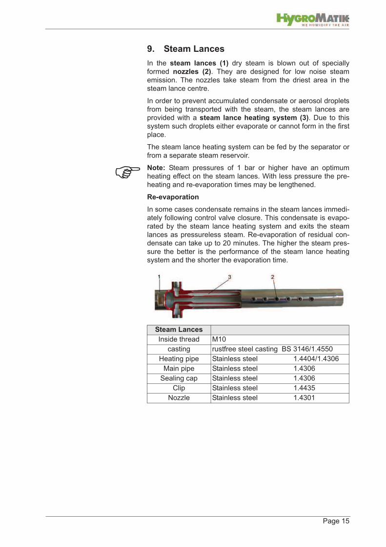
9. Steam Lances
In the steam lances (1) dry steam is blown out of specially
formed nozzles (2). They are designed for low noise steam
emission. The nozzles take steam from the driest area in the
steam lance centre.
In order to prevent accumulated condensate or aerosol droplets
from being transported with the steam, the steam lances are
provided with a steam lance heating system (3). Due to this
system such droplets either evaporate or cannot form in the first
place.
The steam lance heating system can be fed by the separator or
from a separate steam reservoir.
Note: Steam pressures of 1 bar or higher have an optimum
heating effect on the steam lances. With less pressure the pre-
heating and re-evaporation times may be lengthened.
Re-evaporation
In some cases condensate remains in the steam lances immedi-
ately following control valve closure. This condensate is evapo-
rated by the steam lance heating system and exits the steam
lances as pressureless steam. Re-evaporation of residual con-
densate can take up to 20 minutes. The higher the steam pres-
sure the better is the performance of the steam lance heating
system and the shorter the evaporation time.
Steam Lances
Inside thread M10
casting rustfree steel casting BS 3146/1.4550
Heating pipe Stainless steel 1.4404/1.4306
Main pipe Stainless steel 1.4306
Sealing cap Stainless steel 1.4306
Clip Stainless steel 1.4435
Nozzle Stainless steel 1.4301

Page 16
9.1 Technical Data
*h - installation length
*j - total length
*X- Installation length min. 1m (see Steam Lance heating system)
Steam lances are available as type 20 and 40 in various
lengths, suitable for duct widths from 280mm to 3855 mm.
*Duct width is internal dimension
9.2 Number of steam lances
The steam lance system may comprise multiple steam lances.
With a duct height of more than 1000 mm multiple lances should
be positioned horizontally one on top of the other. This ensures
an even steam distribution. See table for number of steam
lances recommended for various duct heights.
Type 20 Type 40
Lance-
code
h
[mm]
j
[mm]
Weight
[kg]
h
[mm]
j
[mm]
Weight
[kg]
1 218 338 0,88 218 345 1,54
1,5 392 512 1,14 392 519 1,97
2 568 688 1,40 568 695 2,39
3 838 958 1,80 838 965 3,03
4 1148 1268 2,26 1148 1275 3,78
5 1408 1528 2,65 1408 1535 4,40
6 1718 1838 3,11 1718 1845 5,15
7 2018 2138 3,55 2018 2145 5,87
8 2318 2438 4,00 2318 2445 6,59
9 2628 2748 4,46 2628 2755 7,34
10 2938 3058 4,92 2938 3065 8,08
11 3238 3358 5,37 3238 3365 8,80
12 3548 3668 5,83 3548 3675 9,55
Inst. length h mm 218 390 568 838 1148 1408 1718 2018 2318 2628 2938 3238 3548
Duct width (max.)* mm 390 565 835 1130 1405 1715 2015 2315 2625 2935 3245 3545 3855
Duct width (min.)* mm 220 395 570 840 1150 1410 1720 2020 2320 2630 2940 3240 3550
Lance code 1 1,5 2 3 4 5 6 7 8 9 10 11 12
Duct height No. of Lancesl
up to 1000 mm 1
1000 - 1700 mm 2
1700 - 2200 mm 3
2200 - 2600 mm 4
over 2600 mm 5

Page 17
Check number of steam lances when the following factors
apply:
• duct air speed exceeds 5 m/s.
• Duct air temperature under 21°C.
• Last fine mesh filter located less than 3 m behind steam
lance.
• Air flow branching occurs less than 1 m behind steam
lance.
Depending upon additional parameters such as pre-defined
steam output, existing or desired absorbtion distance or rise in
humidity the installation of additional lances may improve effi-
ciency.
Steam lance piping for multiple steam lances .
HygroMatik standard supply is for lengths of 300 mm und 450
mm. Distances are approximate and can vary from installa-
tion to installation. Piping should be installed for even lance
distribution along the duct height. Distance between duct floor
and ceiling should not exceed 250 mm.

Page 18
10. Pressure Gauge Station
Installation of a pressure gauge on the steam injection unit
ensures immediate detection of pressure drops or fluctuations.
The HygroMatik Pressure gauge station consists of an up to
200°C temperature-tested, tubular spring pressure gauge (0-
6bar), a T-junction and a dual nipple.
Pressure gauge shut-off valves and fluid-sack pipes are avail-
able on request.
Note: The pressure gauge station is installed in front of the
steam injection unit.

Page 19
11. Ball Float Steam Trap
After separation from the steam inside the separator condensate
is drained out through a ball float steam trap.
11.1 Function
The discharge valve is controlled by the ball float dependent
upon the density of the incoming medium.
Starting Position / Air
When the unit starts, air present in the system is discharged
through the thermostatic air extractor fan.
Normal Operating Conditions / Condensate
As soon as incoming condensate causes the float to rise, it flows
through the valve and extractor fan into the condensate network.
Hot condensate closes the thermostatic extractor but the con-
densate can continue to flow out through the valve.
Steam
If steam enters, the thermostatic extractor closes and the float
descends until the valve closes.
Warning: Water hammers can severely damage the ball float.
condensate loads in outdoor installations increase the risk of
freezing.
Water Hammers: Condensate accumulates in depressions.
During start-up, steam flows over the condensate causing it to
vibrate. This can continue until a certain amount of condensate
is carried off. At the next flow bifurcation this condensate hits the
first available object at a velocity of up to 25m/s. This impact is
known as a water hammer. .
Condensate load: Accumulated condensate which cannot drain
due to a depression.

Page 20
11.2 Technical Data
11.2.1 KS-Condensate Drain for DDS Type A
The KS-Condensate Drain for Type A is integrated into the sepa-
rator.
11.2.2 KS-Condensate Drain for DDS Type C
The KS-Condensate Drain for Type C is an additional unit that is
connected to the separator condensate drain over a connecting
piece.
Screwfitting : 1/2“ external thread
Materials:
Clip 1 Stainless steel 1.4404
Float 2 Stainless Steel 1.4404
Flange seal 3
Soft seal 4
Adjust. screw 5 Stainless Steel 1.4404
Housing 6 Stainless Steel 1.4404
Type Spirax Sarco FT14-4,5
Nominal pressure setting PN16
Screw fitting 1/2“ Internal thread
Dimensions : A 121 mm
B 107 mm
C 67 mm
D 147 mm
E 105 mm
Materials:
Cover 1 Nodular Cast Iron GGG40.3
Screws 2 Steel 8.8
Cover seal 3 nickel-graphite
Housing 4 Nodular Cast Iron GGG40.3
Mainvalve face 5 Stainless Steel 1.4057
Float 6 Stainless Steel 1.4301
Fan 7 Stainless Steel1.4541+1.4057
version type C
version type A

Page 21
12. Thermostatic Capsule Steam Trap
Condensate that has collected in the steam lance heating sys-
tem is discharged through a thermostatic capsule steam trap.
12.1 Function
The discharge valve is controlled dependent upon the capsule
volume and the temperature and pressure of the incoming
medium.
The capsule contains a liquid whose saturation curve parallels
that of steam. However, the liquid boiling point is always some-
what less than that of water.
Starting Position / Air
During the start-up process air and condensate are quickly
drained over the valve which is still in a cold condition.
Steam
If condensate temperature approaches steam saturation tem-
perature due to the steam proximity, capsule pressure becomes
higher than the surrounding condensate. The capsule expands
and closes the valve just before steam can enter the trap.
The temperature at which the closing process begins is 4K
below steam saturation temperature.
Normal Operating Conditions / Condensate
Condensate in the piping before the thermic capsule condensate
drain cools. The capsule medium cools too and opens the valve.
Now the condensate can drain until a temperature increase re-
heats the capsule and closes the valve.
Warning:
Do not insulate the thermic capsule steam trap.
The minimum connection pipe length of 1.0 m between the
lance connection and the drain is absolutely mandatory.

Page 22
12.2 Technical Data
Type Spirax Sarco MST 21
max. operating pressure 18 bar
max. operating temperature 210°C
Dimensions: A 50 mm
B 45 mm
Materials:
Housing 1 Stainless Steel 1.4305
Cover 2 Stainless Steel1.4057
Capsule 3 Stainless Steel 1.4541
Spring 4 Stainless Steel 1.4300
Spacer 5 Stainless Steel 1.4301
Strainer 6 Stainless Steel 1.4301
Fill element Type E

Page 23
13. Humidification Output
The maximum humidification output [kg/h] of one steam injection
unit depends upon the available steam pressure in bar.
Maximum humidification output can be over 700 kg/h and oper-
ating pressure of pmax = 4 bar.
13.1 Output Graphs
The following graphs serve as an aid to determining the neces-
sary Kvs-Values for the control valve, a given steam pressure
and a desired humidification output.
The graphs help to determine whether a Type 20 or Type 40
should be selected.
Type 20 up to approx. 270 kg/h.
Type 40 up to approx. 700 kg/h.
13.2 Determining the control valve Kvs-Value
Control Valve Kvs- Value:
The Kv-Value corresponds to a water flow rate (in m³/h) through
a valve at a pressure difference of 1 bar and a water tempera-
ture of 5 - 30 °C.
A Kv-Value is valid only for the corresponding valve lift of a
valve. The Kv-Value of a valve at nominal lift (100% open) is
described as the Kvs-Wert. Using the Kvs-Value one can deter-
mine the maximum possible flow.
Kv flow figure [m³/h]
Kvs Valve coefficient [m³/h]
Page 24
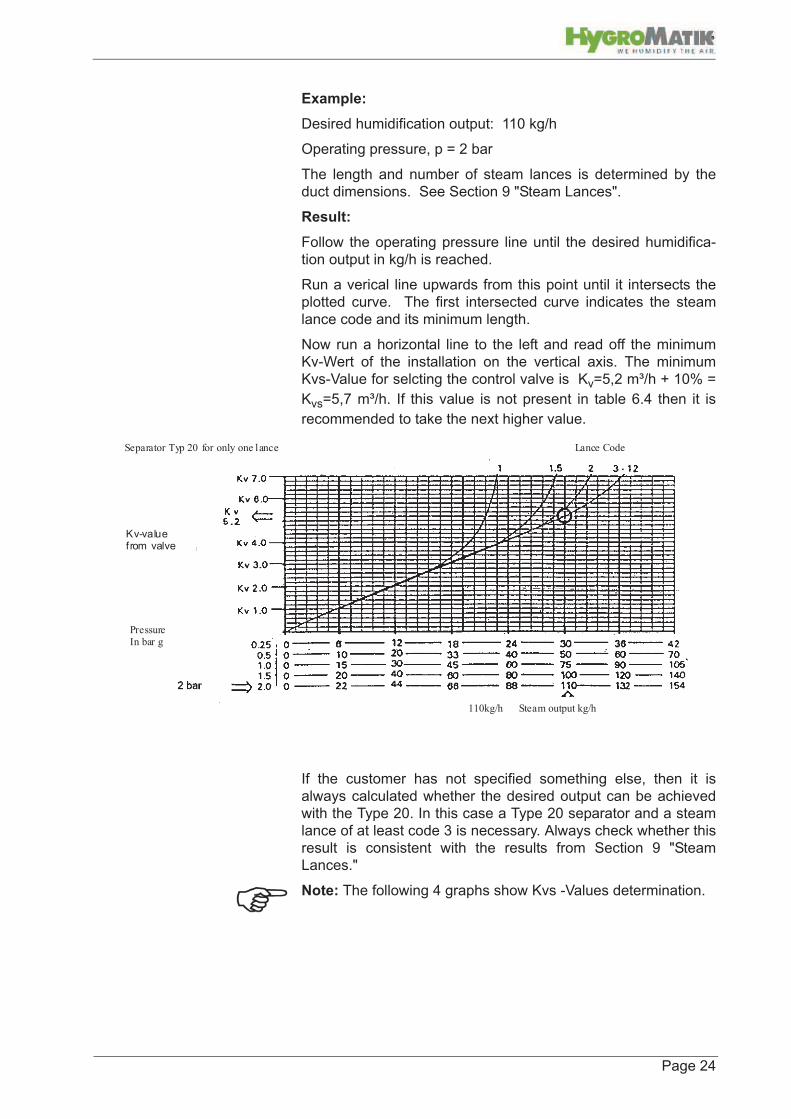
Example:
Desired humidification output: 110 kg/h
Operating pressure, p = 2 bar
The length and number of steam lances is determined by the
duct dimensions. See Section 9 "Steam Lances".
Result:
Follow the operating pressure line until the desired humidifica-
tion output in kg/h is reached.
Run a verical line upwards from this point until it intersects the
plotted curve. The first intersected curve indicates the steam
lance code and its minimum length.
Now run a horizontal line to the left and read off the minimum
Kv-Wert of the installation on the vertical axis. The minimum
Kvs-Value for selcting the control valve is Kv=5,2 m³/h + 10% =
Kvs=5,7 m³/h. If this value is not present in table 6.4 then it is
recommended to take the next higher value.
If the customer has not specified something else, then it is
always calculated whether the desired output can be achieved
with the Type 20. In this case a Type 20 separator and a steam
lance of at least code 3 is necessary. Always check whether this
result is consistent with the results from Section 9 "Steam
Lances."
Note: The following 4 graphs show Kvs -Values determination.
Separator Typ 20 for only one lance Lance Code
110kg/h Steam output kg/h
Pressure In bar g
Kv-value from valve
Page 25
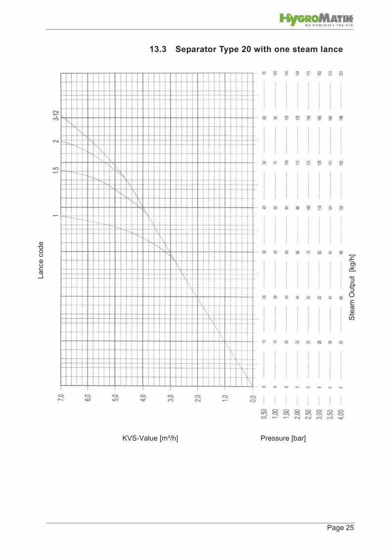
13.3 Separator Type 20 with one steam lance
KVS-Value [m³/h] Pressure [bar]
Ste
am
Ou
tpu
t [
kg
/h]
La
nce
cod
e

Page 26
13.4 Separator Type 20 with multiple steam lances
KVS-Value [m³/h] Pressure [bar]
ste
am
ou
tput
[kg/h
]
La
nce
co
de

Page 27
13.5 Separator Type 40 with one steam lance
KVS-Value[m³/h] Pressure [bar]
ste
am
ou
tpu
t [kg
/h]
Lan
ce
co
de

Page 28
13.6 Separator Type 40 with multiple steam lances
ste
am
ou
tpu
t [kg
/h]
KVS-Value [m³/h] Pressure [bar]
La
nce
co
de

Pa
ge
29
14
.G
rap
h fo
r De
term
ing
Ab
so
rptio
n D
ista
nc
eAbsorption Distance: distance from the steam outlet until the end of the visible trail
Outlet
rel. humidity in [%]
35°C
55%
65%
75%
35%
45%
Inlet
40
rel. humidity in [%]
7080 5060 102030
20°C25°C
30°C
15°C
23°C
40%55%
Example:given parameters:
3.0
normal absorption distance [m]
1,0m
2,8m/s
absorption distance (ad)=1,25m
2.0 2.51.00.5 1.5
result:
nr. of steam lances: 1
3.5
2.0humidity sensor:
fine mesh filter:
downstream obstructions:
factors affecting
particle filter: Ad x 2,5
Ad x 1,5
Ad x 5,0
6.0
air speed [m/s]
7.0
8.0
4.05.0
3.0
0.9
duct height quotient [m]
by number of steam lances
0.4
1.0 0.3
0.7
0.6
0.5
0.8 1.0
air temperature, duct
rel. humidity, inlet:rel. humidity, outlet:
air speed:
duct height:
air temperature, duct:

Page 30
15. Installation
Please read this instruction manual in order to install the Hygro-
Matik steam injection humidifier in a safe and proper manner.
Warning: this steam injection humidifier may only be installed by
qualified personnel. HygroMatik can accept no responsibility for
any damage caused by incorrect installation.
Please observe all safety and hazard instructions supplied with
the steam injection humidifier.
The actuator must be disconnected from voltage before begin-
ning installation.
Installation of any additional units is only permitted following writ-
ten permission by the manufacturer, otherwise all guarantees
are null and void.
Individual packing should be opened at the installation site. This
can prevent damage to individual items.
Note: HygroMatik steam injection humidifiers are delivered
largely pre-assembled. If individual components are in the deliv-
ery then all installation instructions concerning those items are to
be followed.
Normally the steam supply supports are sufficient to support the
steam injection system. Should this not be the case then extra
supports must be provided (for instance using a fixed and sup-
ported U profile arrangement).
Warning: Steam lance fittments are not suitable to support the
entire humidification unit.
Note: Supports are to be done on site.

Page 31
15.1 Attaching steam pipes
Warning: when installing please observe the following:
• all work is to be done by qualified personnel only.
• follow local regulations.
• Use only steam with a minimum pressure of 0,5 bar and a
mximum pressure of 4 bar.
• Use only steam with no chemical additives.
• Dimension the on-site steam connections (insulated) so
that a steam velocity of 25 m/s is not exceeded.
HygroMatik recommends the installation of a shut-off valve in
front of the steam injection system in order to facilitate any
necessary maintenance work.
Installing the steam pipes
Steam piping must be installed using state-of-the-art methods.
Steam piping must be installed inclined. They must be fitted
using a suitable pitch and suitable materials. The piping holders
must allow for lateral movement. In more lengthy installations
expansion fittments must be used to avoid expansion stresses.
Warning: Water hammers are dangerous and can cause bodily
harm.
It is necessary to drain off any low angles in order to ensure that
condensate is not drawn along and to avoid water hammers.
Very long steam piping systems must also be drained regularly.
Steam connections must be fitted to the piping upper surface in
order that condensate is not drawn into the piping system.
The HYGROMATIK steam injection system must have a filter
installed in front of the system. This is delivered with the system
or is already installed on-site.

Page 32
15.2 Electrical Installation
If control valve and actuator are included in the delivery, then
operating and installation instructions are provided.
If control units from other manufacturers are used then the cus-
tomer must check their compatibilty to the steam injection sys-
tem.
Warning: Please observe local regulations .
Electrical installation of the actuator may only be done by quali-
fied electrical personnel.
Connect electrical connections according to the wiring diagrams.
A humification control is required for the operation of the humidi-
fier. This is to be installed according to the manufacturers
instructions.
We recommend the use of a Max-Hygrostat in the safety chain.
The Max-Hygrostat serves as a safety element in the case of a
malfunction of the humidity sensor. Install the Hygrostat approx.
2 - 3 m behind the humidifier in the ducting.
Install a pressure sensor in the ducting and integrate this into the
safety chain. The pressure sensor prevents an over-humidifica-
tion of the ducting in the case of a malfunctioning fan.
HygroMatik Actuator wiring diagram
Circuitry for alternative actuators are to be found in the relevant
installations documents.
ControllerA
Actuator
B-4115001
Electrical Start-up
Safety Switch
0V
24V
- V
olta
ge
Su
pp
ly
0 -
10
V C
on
tro
l S
ign
al
0 -
10
V,
for
fabri
ca
tio
n D
DC

Page 33
15.3 Separators
Warning: Before installation, check out the steam supply piping.
It must be established that the steam humidifier is supplied with
as dry a steam as possible (steam with as little condensate as
possible).
Steam pressure at the separator entry point must not exceed 4
bar.
Steam humidifier operating pressure must be kept at a constant
level. It is possible that in order to generate contsant pressure,
pressure reduction stations may be required.
It must be guaranteed the steam supplying the steam humidifier
is as dry as possible. Check that the steam supply lines are
equipped with the necessary condensate drains.
The supply line for the steam humidifier must be taken from the
highest point in the main supply line.
Install a filter in the steam supply line directly in front of every
humidifier. This is the only way to ensure that no foreign objects
can find their way into the humidification unit.
Keep the piping connections as short as possible. In this way
the energy losses are reduced, the system can heat up quicker,
condensates are minimised and the system overall efficiency is
increased.

Page 34
15.4 Control Valve and Actuator
If the valve is on site then the necessary connections between
valve and separator are fitted. All other parts are delivered sep-
arately (e.g. connection bolts and flange seals).
Only actuators which are suitable and certified for steam regula-
tion may be used.
Actuators must have a fail-safe function in order to prevent an
uncontrolled over-humidification in the case of a power failure.
Dirt between the valve face and cone prevent proper closing.
Therefore install a filter directly in front of the separator.
Warning: Control air for pneumatic actuators must be free from
oil and humidity.
If control valves and actuators are part of the delivery then oper-
ating and installation instructions are present.
Customer is responsible for checking steam injection humidifier
compatibilty if control units from other manufacturers are used.
Actuator and valve installation positioning

Page 35
15.5 Pneumatic Start-up safety feature
Note: Pneumatic start-up safety is set at 96°C. This value can
be altered only by the manufacturer.
First install a T-piece with a 1/2" exit in the condensate piping in
front of the condensate drain.
A T-piece with a 1/8" exit is also installed in the control air piping.
A temperature sensor is screwed into the T-piece in the conden-
sate piping.
The 1/8" drain valve is installed in the air control piping in the T-
piece.
Warning: Take great care not to damage the capillary by bend-
ing.

Page 36
15.6 Steam Lances
With single lance systems the lance is fitted directly onto the
valve exit using the delivered fittments.
If multiple lances are necessary to distribute steam in the duct-
ing, then a there is a complete assembled steam lance piping in
the delivery. Angle pieces for installation of humidifier/valve unit
parallel to ducting walls are available from HygroMatik.
In order to reduce the absorbtion distance the steam from the
lance should be directed opposed to the air direction in the duct-
ing.
All piping seals should be done with temperature resistent
(>150°C) sealing tape.
If only one lance is required for even steam distribution install
this at duct half-height.
With a multiple lance system position the lances so that there is
an even steam distribution over the duct cross section and
ensuring that the necessary duct wall distance is guaranteed.
HygroMatik can supply stainless steel standard modules for
lance pitches of 300 und 450 mm.
*X- Pipe length min. 1m (see Section Steam lance heating system)
The distance bewteen lance and duct ceiling or floor should be a
minimum of 200 mm.
Before the lance is installed in the duct check that the correct
lance is present. The steam lance should be utilised over the
entire duct width (Please observe the lance codes).
Steam lances are pressed into the appropriate holes.
Steam lance nozzles should be position opposed to the air flow.
Note: at 0.5 bar to 2.0 bar steam pressure there is a minimum
distance of 200 to 300 mm to existing elements which must be
kept to. Higher pressures and/or sensitive elements need 500
mm.

Page 37
In order to prevent steam condensing on the duct inner walls the
lances should be installed according to the following dimen-
sions:
*„k“ is the necessary drill diameter in the duct wall
A duct wall thickness of 30mm is assumed. If „m“ is larger than
30mm, then the distance „q“, is to be reduced by the difference
m-30mm.
After the lance is positioned, an angle is positioned on the oppo-
site duct wall side at the same height. The screws are self tap-
ping. Then the necessary threaded bar length „y“ is measured.
y = z + 20mm
Warning: a gap x“ between bar end and duct inner wall must be
present in order to accomodate a lance lateral expansion.
Warning: Steam lances from code 2 on must be supported at
the end.
Dimension [mm] F k m q
Type DDS 20 M10 38 30 20-80
Type DDS 40 M10 54 30 20-80

Page 38
* In installation set B-4600100.
Lance guide is installed in the following manner:
- feed bar through hole in angle .
- Screw M10 bar end in the steam lance.
- use nut to lock to lance.
Alternatively, the lance can be installed from the duct ceiling with
a threaded bar or held in a U pipe. The necessary parts thereto
are to be supplied on site.
After the lance has been installed the gap between duct outer
wall and lance is closed using the two cover plates as supplied
with the steam lances. The cover plates are attached using two
self tapping panel screws. The sealing between cover and duct
wall should be done with silicone or a rubber sealant.
Number Description
1 Duct wall
2* Screw M6x35
3* Nut M10
4 Steam Lance
5* Threaded bar M10 & M8 x 250
6* Angle
7* anti-vibration collar

Page 39
15.7 Installation Examples
Note: If lances are positioned vertically then the steam supply
piping should have an additional float controlled condensate
drain.

Page 40
Position lances in the duct centre if possible.
If the humidifier blows into a compact multi-zone unit then it
should be installed directly in the air flow and as close as possi-
ble to the fan.
The bifurcated pipe should never be installed less than one
meter in front of the fan suction side. In this case the correct
installation is behind the fan.
Never install the lances pointing vertically downwards. This
would cause condensate to collect in the steam lance heating
system. On the other hand a vertical installation pointing
upwards is possible.
If the ducting is taller than it is wide, install the steam lance verti-
cally. If this is not possible then a second lance must be installed
in order to ensure an even steam distribution.
Lances should have a minimum distance of 5x the absorbtion
distance to the duct humidity controller.
When selecting the lance choose a size sufficient for the entire
duct width or height.

Page 41
15.8 Steam Lance Heating System
Warning: the line to the heating system must be able to tolerate
pressures of up to maximum 8 bar.
Note: the pipe is easy to bend with a suitable tool. The customer
must adjust the pipe in accordance the conditions on site. Take
care not to kink the pipe when bending.
Observe minimum bend radius of 1,5 x diameter
(here:1,5 x 8mm= 12mm)
Note: Alternatively it is possible to close off the connection to the
separator and feed the steam lance heating system from
another separate steam reservoir with a maximum pressure of 4
bar. Higher steam lance heating temperatures result from higher
pressure and cause an even better heating heating effect.
Installation of the steam lance heating system follows the instal-
lation of the steam injection system including steam lances. In
accordance with the dimensions of the humidifier unit a pipe with
an external dimension of 8mm is bent to shape and installed with
the help of the supplied pipe fittings.
*1 - Heating piping using a separate dry steam reservoir
*2 - Connecting pipes between separator and steam lance
Pipe length „X“ must be at least 1 Meter to ensure effective
functioning of the capsule condensate drain. There are various
installation possibilities, also where there is little room. Important
here is to ensure the optimum vertical positioning of the capsule
condensate drain. Pressure in the condensate piping must not
exceed half the pressure in the heating piping. Piping must
always be installed properly inclined.

Page 42
15.9 Check List
Warning: The steam injection humidifier may only be operated
by qualified and authorised personnel.
Before switching on the steam injection humidifier please check
for correct installation by going through the following check list:
- Have the steam supply lines been flushed out?
- Are the steam supply and condensate lines properly connected
and secure?
- Has the entire steam supply line up to the control valve been
checked for leaks?
- Is the specified system pressure present?
- Is there a proper filter fitted before the separator ? (normally
part of the system delivery)
- Is the operating pressure at least 0,5 bar and maximum 4 bar?
Electrical installation checks must be carried out in accordance
with customer requirements and public power utility regulations.
All electrical connections must be according to the circuit wiring
diagrams.

Page 43
16. Initial Operation
Warning: the steam injection humidifier may only be operated
by qualified personnel.
Warning: for actuator initial operation please refer to the instruc-
tions of the regulator and/or installations company. Initial opera-
tion should only be done by a trained expert or service
technician.
Warning: Follow the instructions below to ensure correct opera-
tion of your steam injection humidifier.
Note: during most installations dirt will have managed to enter
the steam supply. Therefore it is advisable to flush out the piping
before initial operation.
Turning off the steam injection humidifier
Before starting up the steam injection humififier it is essential to
know how to switch it off.
Close shut-off valve on the steam supply to the separator .
If applicable, also close the shut-off valve to the separate steam
supply to the steam lance heating heating system.
Turning the steam injection humidifier on
Warning: If the actuator is not a controlled actuator then verify
that the control valve is in the closed position.
Slowly open the separator shut-off valve and, if there is one
present, the shut-off valve to the steam lance heating system.
Check the entire steam supply up to the control valve for leaks.
Repair leaks as necessary.
Check specified system pressure using the pressure gauge.
Wait 10 - 15 minutes so that the steam injection humidifier can
warm up. The pipes between the separator and the steam trap
should be about the same temperature.

Page 44
Set the Max. Hygrostat to the desired value. Set the humidity
sensor to the desired value and activate the actuator.
Note: Periodic filter cleaning is recommended in order to pre-
vent the control valve from excessive wear. Before cleaning the
filter always shut off the steam supply and allow the system to
cool down.
The following operations are active:
• Accumulated condensate in the steam supply is forced
into the separator where it is fed into the condensate net-
work via the ball float steam trap.
• Some of the dry steam in the top top part of the separator
supplies the steam lance heating system and heats the
steam lances.
• As soon as the actuator indicates that steam is required
the control valve opens and sends steam into the steam
lances.
Note: for units with a start-up safety switch the control valve is
released only when the piping between separator and ball float
steam trap has reached its designated temperature.

Page 45
17. Maintenance
The HygroMatik steam injection humidifier is easy to maintain.
However, inadequate or improper maintenance can lead to oper-
ational malfunctions. Regular maintenance is essential so that
your steam injection humidifier achieves a long, trouble free life
span.
Warning: when performing maintenance work please note:
• The steam injection humidifier is only to be serviced by
qualified and authorised personnel.
• Follow safety instructions.
• Switch off the humidifier and protect against re-start. Allow
the humidifier to cool down.
• After performing maintenance work have the steam injec-
tion humidifier checked for safe operation by qualified per-
sonnel.
The steam injection humidifier‘s performance and maintenance
intervals depend primarily upon the steam quality and the
humidification volume since the last maintenance. Different
steam quality can shorten or lengthen maintenance intervals.
17.1 Maintenance work
recommendations on maintenance intervals are based exclu-
sively upon typical, empirically established values.
17.2 Strainer
Warning: before beginning any maintenance procedure make
sure that the feed and drain are shut off and that the unit is cool
and not under pressure.
Maintenance „DDS Type A“
» Loosen the screws (M12/M16) on the flange connection
(D) at the steam entry point. Warning: steam supply
and DDSystem should be fixed according to the
assembly instructions
» Steam supply pipes should be pulled free of the entry
flange if possible.
» If there is not enough room to exchange the filter then
de-install the separator.
» Exchange filter (C) and seal (B).
» Re-connect the flange with seal to the steam entry
point.
» Check the flange for leakage after re-starting the sys-
tem.
See next section for maintenance materials
A B C D

Page 46
Maintenance „DDS Type C“
» Unscrew filter holder (C) , (SW27 or SW50).
» Extract filter (B) and clean or replace.
» Replace seal (A).
» Re-position filter.
» Screw filter holder in.
» Check for leakage by re-start
17.3 Ball float condensate drain
Warning: Before beginning any maintenance work please check
that supply and drainage are shut off and that the unit is pres-
sure free and cool.
Maintenance „DDS Type A“
» Release condensate drain from separator.
» Loosen both Allen screws (size 6/8) of the lower sepa-
rator screw clamp and remove clamp (A).
» Release lower separator part (B)
» Remove C clamp (C).
» Release cone (D) with seal (E)
» Loosen seal screw and replace seal if necessary.
» Tighten seal screw a little and lock down with nut
without damaging the seal.
» Re-fit cone and seal and fix at the separator base using
C clamp.
» Position new flange seal (F) at the bottom and fix with
screw clamp to the separator.
» Screw down both Allen screws simultaneously.
» Check for leakages by re-start.
Use only original HygroMatik parts.
Maintenance set for DDS 20 Type A: B-4111917
Maintenance set for DDS 40 Type A: B-4111919
The maintenance sets include 1x sieve filter, flange seal, steam
supply entry seal, and seals for the ball float and drain.
Maintenance „DDS Type C“
Warning: when re-assembling please check that all sealing
faces are clean and have a thin coat of sealing paste.
Exchanging main valve
» Loosen cover screws (U), (SW17), and lift cover.
» Loosen both valve screws (D) and remove complete
float unit (E-C).
» Screw out main valve (A), (SW17) and remove seal
(B).
» Replace seal (B) and fit in new main valve.
D E F C A B

Page 47
» Screw down new complete float unit (E-C) with valve
screws (D) .
» Screw down cover with new seal (T).
Use HygroMatik spare parts number E-4111834
Exchanging air vent
» Loosen C spring clamp (L).
» Remove capsule element (H) and spacer (M).
» Unscrew valve seat (J) (SW17).
» Screw down valve holder (N), new seal (B), with new
valve seat (J).
» Fit in spacer (M) and capsule unit (H).
» Fit spring clamp (L).
Use HygroMatik part number E-4111836
17.4 Thermostatic Capsule Steam trap typeMST21
Warning: Before beginning any maintenance operation make
sure that the feed and drain are shut off and that the unit is cool
under not under pressure.
Replacing Capsule Element Set
» When the unit is cold, unscrew cover using a SW 22 or
SW 32 wrench.
» Remove strainer (A), spring (B), capsule (C) and
spacer (D).
» Apply a light coating of sealing paste to the cap threads.
» Assemble new capsule element set in the proper
sequence.
» Note: cap torque specifications: 110 Nm.
» Check steam injection unit for correct functioning.
» Start up unit and operate for 15 minutes ideally at maxi-
mum output.
» Check safety features.
» Check pipe connections for possible leakage.
Use HygroMatik part number E-4111828.

Page 48
18. Malfunctions
Problem Possible Cause to do
No steam is coming
out of steam lance
• Defective Hygrostat or humidity
sensor
• Defective Control Valve
• Defective Actuator
• Inaccurate or defective control
• Fouled or blocked coarse strainer in
the filter before separator
• Shut-off valve in steam supply line
is closed.
• Pressure reduction valve, if instal-
led, is out of order.
• Check Hygrostaten and/or
humitiy sensor and repair
or replace as necessary.
• Check valve and clean it
or replace as necessary.
• Measure control signal.
Check, repair or replace
as necessary.
• Check actuator, reset,
repair or replace.
• Remove coarse strainer
and clean or replace.
• Open shut-off valve
• Clean pressure reduction
valve, possibly reset ope-
rational pressure.
Steam is coming
out of steam lance
although desired
humidity value is re-
ached.
• Foreign objects between valve cone
and face prevent valve from closing
properly.
• Defective or falsely set Hygrostat or
humidity sensor .
• Actuator does not close properly.
• Residual condensate evaporates in
the steam lance and exits the lance
as pressureless steam (re-evapora-
tion effect) This process can take up
to 20 minutes.
• Check and clean valve
valve .
• Check humidity or Hygros-
tat and re-set or repair.
• Re-adjust actuator to cont-
rol valve.
• Check out steam supply
pressure for the steam
lance heating system.
Supply steam lance hea-
ting system from a sepa-
rate dry steam steam
reservoir (max. 4 bar).
Condensate is co-
ming out of steam
lance
• Improper steam supply installation
to the humidifier.
• Defective or fouled steam trap eit-
her for separator or steam lance
heating system.
• Back pressure from condensate
network is higher than the operating
steam injection humidifier pres-
sure.
• Check Installation.
• Clean or replace steam
trap.
• Reduce pressure in the
condensate return line.
• If this is not possible, con-
nect steam trap to sepa-
rate return line.

Page 49
Warning: The unit must be switched off immediately if it is mal-
functioning. Malfunctions may only be repaired by qualified per-
sonnel under observation of all safety instructions.
Problem Possible Cause to do
Condensate is co-
ming out of steam
lance.
• Steam trap drain is considerably
higher that the DDSystem.
• Start-up safety feature does not
work properly.
• Defective or unsuitable thermostatic
capsule condensate drain attached
to steam lance heating system.
• Steam heating for steam lance hea-
ting system insufficient.
• Install condensate drain
beneath the humidifier
level and pump out the
resultant condensate to a
suitable place.
• Check wiring and function
of start-up safety feature.
• Check out condensate
drain and integrated ele-
ments. Type E must be
used. Clean condensate
drain.
• Optimum heating effect
occurs from pressure over
1 bar. Less pressure can
lead to lengthier pre-hea-
ting times.

Page 50
19. Dismantling
After the steam injection humidifier is no longer in use it must be
dismantled (scrapped and disposed of) following the installation
procedures in reverse order.
Warning: Dismantling the unit may only be done by trained and
qualified personnel, the electrical dismantling by trained electro-
personnel.
The information in section "Safety Instructions" especially the
disposal regulations are to be observed.

Page 51
20. Steam Injection System dimensions and
Installation Schematic.
* Steam injection system Type A (stainless steel)
*Steam Injection system Type C (Mixed materials)
*all dimensions in mm!
Standard dimensions 300 and 500; other graduations possible on request
Page 52
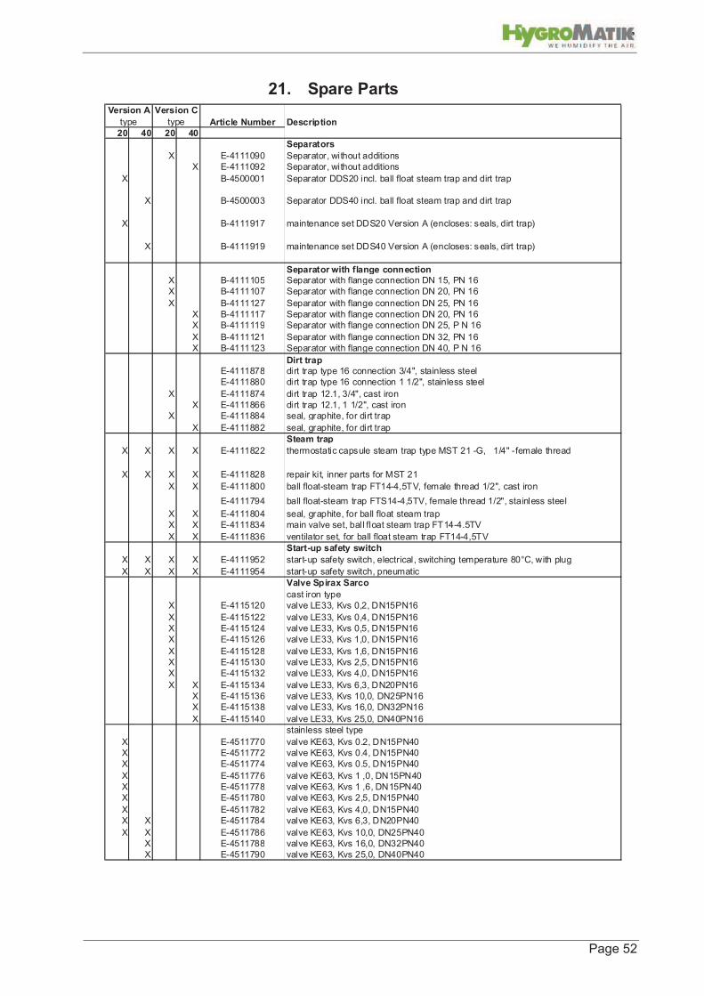
21. Spare Parts
Article Number Description
20 40 20 40
Separators
X E-4111090 Separator, without additions
X E-4111092 Separator, without additions
X B-4500001 Separator DDS20 incl. ball float steam trap and dirt trap
X B-4500003 Separator DDS40 incl. ball float steam trap and dirt trap
X B-4111917 maintenance set DDS20 Version A (encloses: seals, dirt trap)
X B-4111919 maintenance set DDS40 Version A (encloses: seals, dirt trap)
Separator with flange connectionX B-4111105 Separator with flange connection DN 15, PN 16
X B-4111107 Separator with flange connection DN 20, PN 16
X B-4111127 Separator with flange connection DN 25, PN 16
X B-4111117 Separator with flange connection DN 20, PN 16
X B-4111119 Separator with flange connection DN 25, P N 16
X B-4111121 Separator with flange connection DN 32, PN 16
X B-4111123 Separator with flange connection DN 40, P N 16
Dirt trapE-4111878 dirt trap type 16 connection 3/4", stainless steel
E-4111880 dirt trap type 16 connection 1 1/2", stainless steel
X E-4111874 dirt trap 12.1, 3/4", cast iron
X E-4111866 dirt trap 12.1, 1 1/2", cast iron
X E-4111884 seal, graphite, for dirt trap
X E-4111882 seal, graphite, for dirt trap
Steam trap
X X X X E-4111822 thermostatic capsule steam trap type MST 21 -G, 1/4" -female thread
X X X X E-4111828 repair kit, inner parts for MST 21
X X E-4111800 ball float-steam trap FT14-4,5TV, female thread 1/2", cast iron
E-4111794 ball float-steam trap FTS14-4,5TV, female thread 1/2", stainless steel
X X E-4111804 seal, graphite, for ball float steam trap
X X E-4111834 main valve set, ball float steam trap FT14-4.5TV
X X E-4111836 ventilator set, for ball float steam trap FT14-4,5TV
Start-up safety switch
X X X X E-4111952 start-up safety switch, electrical, switching temperature 80°C, with plug
X X X X E-4111954 start-up safety switch, pneumatic
Valve Spirax Sarco
cast iron type
X E-4115120 valve LE33, Kvs 0,2, DN15PN16
X E-4115122 valve LE33, Kvs 0,4, DN15PN16
X E-4115124 valve LE33, Kvs 0,5, DN15PN16
X E-4115126 valve LE33, Kvs 1,0, DN15PN16
X E-4115128 valve LE33, Kvs 1,6, DN15PN16
X E-4115130 valve LE33, Kvs 2,5, DN15PN16
X E-4115132 valve LE33, Kvs 4,0, DN15PN16
X X E-4115134 valve LE33, Kvs 6,3, DN20PN16
X E-4115136 valve LE33, Kvs 10,0, DN25PN16
X E-4115138 valve LE33, Kvs 16,0, DN32PN16
X E-4115140 valve LE33, Kvs 25,0, DN40PN16
stainless steel type
X E-4511770 valve KE63, Kvs 0.2, DN15PN40
X E-4511772 valve KE63, Kvs 0.4, DN15PN40
X E-4511774 valve KE63, Kvs 0.5, DN15PN40
X E-4511776 valve KE63, Kvs 1 ,0, DN15PN40
X E-4511778 valve KE63, Kvs 1 ,6, DN15PN40
X E-4511780 valve KE63, Kvs 2,5, DN15PN40
X E-4511782 valve KE63, Kvs 4,0, DN15PN40
X X E-4511784 valve KE63, Kvs 6,3, DN20PN40
X X E-4511786 valve KE63, Kvs 10,0, DN25PN40
X E-4511788 valve KE63, Kvs 16,0, DN32PN40
X E-4511790 valve KE63, Kvs 25,0, DN40PN40
Version A Version C
type type

Page 53
Article Number Description
20 40 20 40
Steam lance
X X E-4111000 steam lance 20, Code 1, 218 mm fitting lenght
x X E4111002 steam lance 20, Code 1.5, 393 mm fitting lenght
X X E-4111004 steam lance 20, Code 2, 568 mm fitting lenght
X X E-4111006 steam lance 20, Code 3, 838 mm fitting lenght
X X E-4111008 steam lance 20, Code 4, 1148 mm fitting lenght
X X E-4111010 steam lance 20, Code 5, 1408 mm fitting lenght
X X E-4111012 steam lance 20, Code 6, 1718 mm fitting lenght
X X E-4111014 steam lance 20, Code 7, 2018 mm fitting lenght
X X E-4111016 steam lance 20, Code 8, 2318 mm fitting lenght
X X E-4111018 steam lance 20, Code 9, 2628 mm fitting lenght
X X E-4111020 steam lance 20, Code 10, 2938 mm fitting lenght
X X E-4111022 steam lance 20, Code 11, 3238 mm fitting lenght
X X E-4111024 steam lance 20, Code 12, 3548 mm fitting lenght
X X E-4111050 steam lance 40, Code 1, 217 mm fitting lenght
X X E-4111052 steam lance 40, Code 1.5, 392 mm fitting lenght
X X E-4111054 steam lance 40, Code 2, 567 mm fitting lenght
X X E-4111056 steam lance 40, Code 3, 837 mm fitting lenght
X X E-4111058 steam lance 40, Code 4, 1147 mm fitting lenght
X X E-4111060 steam lance 40, Code 5, 1407 mm fitting lenght
X X E-4111062 steam lance 40, Code 6, 1717 mm fitting lenght
X X E-4111064 steam lance 40, Code 7, 2017 mm fitting lenght
X X E-4111066 steam lance 40, Code 8, 2317 mm fitting lenght
X X E-4111068 steam lance 40, Code 9, 2627 mm fitting lenght
X X E-4111070 steam lance 40, Code 10, 2937 mm fitting lenght
X X E-4111072 steam lance 40, Code 11, 3237 mm fitting lenght
X X E-4111074 steam lance 40, Code 12, 3547 mm fitting lenght
PipingX X X X E-4111980 Pipe 8x1mm, for pre heating system
X X E-4111984 Connecting screw, for lance heating, steel zinc plated
X X E-4112984 Connecting screw, for lance heating, stainless steel
X X B-4111981 steam lance piping in center for 2 lances, type 20, 300 mm fitting lenght
X X B-4111983 steam lance piping in center for 2 lances, type 20, 450 mm fitting lenght
X X B-4111989 steam lance piping in center for 2 lances, type 40, 300 mm fitting lenght
X X B-4111991 steam lance piping in center for 2 lances, type 40, 450 mm fitting lenght
X X B-4111935 connection for another steam lance, type 20, 300 mm lenght
X X B-4111937 connection for another steam lance, type 20, 450 mm lenght
X X B-4111943 connection for another steam lance, type 40, 300 mm lenght
X X B-4111946 connection for another steam lance, type 40, 450 mm lenght
Actuator and accessories
X X X X B-4115001 actuator, electrical, 24V/0-10V or 4-20mA control signal
X X X X E-4115082 actuator pneumatic, PN9220E, control signal 0,2 - 1 bar proportional, wihtout
accessories
E-4111662 EP5 positioner, electropneumatic
E-4111666 PP5 positioner, pneumatic, control signal 0,2 - 1,0 bar
E-4111668 gauge block for PP5, complete with 1 x 2barg and 1 x 7barg
Version A
type
Version C
type

Page 54
22. Fax Form - Order for spare parts
Lise-Meitner-Str. 3
24558 Henstedt-Ulzburg
Tel. 04193/895-0
Spare Parts Fax Order Form
for Unit -Type *______________ Serial-Nr.* ___________________
From Department: ______________ Order Number: __________________
Delivery: Express Delivery quickly as possible in ... Weeks
Delivery Address (if different)
__________________________
__________________________
__________________________
__________________________
* Please be sure to state unit type and serial number to ensure that you receive your ordered parts
as quickly as possible. Thank You.
Number of pieces Article Description Article Number
Fax Form
Please copy, fill out and fax to:
Fax.Nr. 04193/895-33
Stamp (Invoicing address )
Date/Signature


12/2004
Lise-Meitner-Str.3 • D-24558 Henstedt-Ulzburg
Phone +49(0)4193/ 895-0 • Fax -33
eMail [email protected] • www.hygromatik.com
A member of the Group