Steam Injection Humidifiers
12
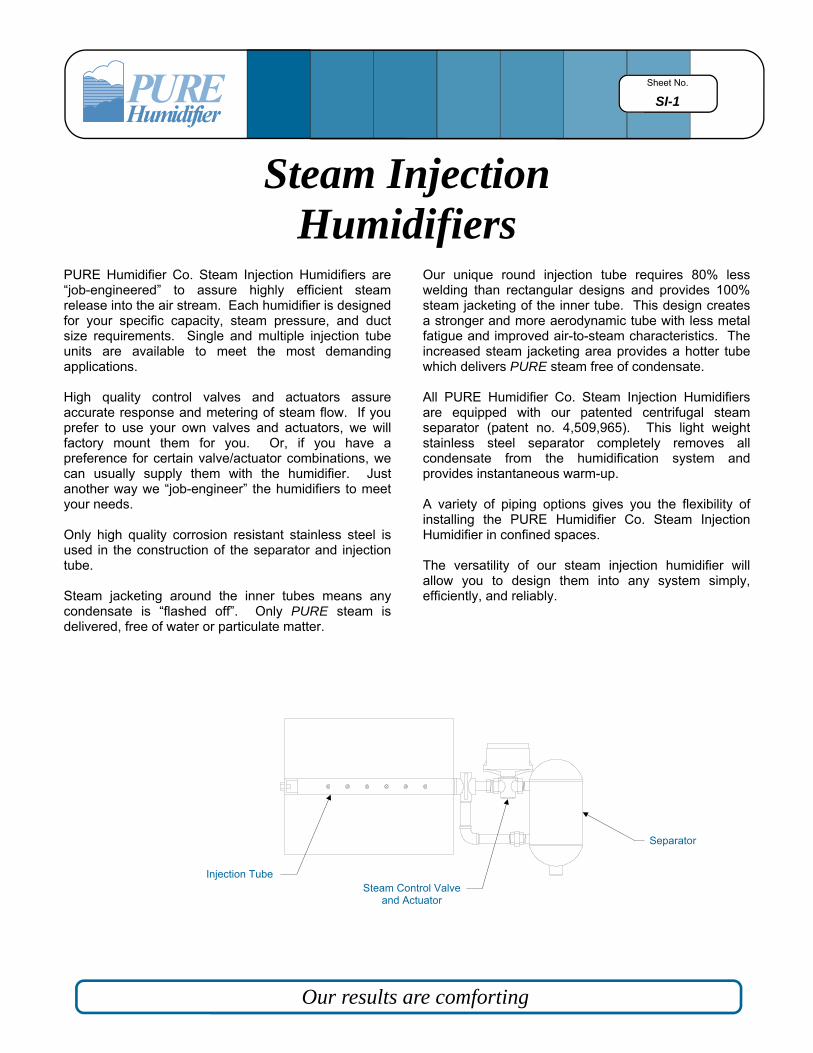
Sheet No. SI-1 Steam Injection Humidifiers PURE Humidifier Co. Steam Injection Humidifiers are “job-engineered” to assure highly efficient steam release into the air stream. Each humidifier is designed for your specific capacity, steam pressure, and duct size requirements. Single and multiple injection tube units are available to meet the most demanding applications. High quality control valves and actuators assure accurate response and metering of steam flow. If you prefer to use your own valves and actuators, we will factory mount them for you. Or, if you have a preference for certain valve/actuator combinations, we can usually supply them with the humidifier. Just another way we “job-engineer” the humidifiers to meet your needs. Only high quality corrosion resistant stainless steel is used in the construction of the separator and injection tube. Steam jacketing around the inner tubes means any condensate is “flashed off”. Only PURE steam is delivered, free of water or particulate matter. Our unique round injection tube requires 80% less welding than rectangular designs and provides 100% steam jacketing of the inner tube. This design creates a stronger and more aerodynamic tube with less metal fatigue and improved air-to-steam characteristics. The increased steam jacketing area provides a hotter tube which delivers PURE steam free of condensate. All PURE Humidifier Co. Steam Injection Humidifiers are equipped with our patented centrifugal steam separator (patent no. 4,509,965). This light weight stainless steel separator completely removes all condensate from the humidification system and provides instantaneous warm-up. A variety of piping options gives you the flexibility of installing the PURE Humidifier Co. Steam Injection Humidifier in confined spaces. The versatility of our steam injection humidifier will allow you to design them into any system simply, efficiently, and reliably. Our results are comforting Separator Steam Control Valve and Actuator Injection Tube
Transcript of Steam Injection Humidifiers
Sheet No.
SI-1
Steam Injection Humidifiers
PURE Humidifier Co. Steam Injection Humidifiers are “job-engineered” to assure highly efficient steam release into the air stream. Each humidifier is designed for your specific capacity, steam pressure, and duct size requirements. Single and multiple injection tube units are available to meet the most demanding applications. High quality control valves and actuators assure accurate response and metering of steam flow. If you prefer to use your own valves and actuators, we will factory mount them for you. Or, if you have a preference for certain valve/actuator combinations, we can usually supply them with the humidifier. Just another way we “job-engineer” the humidifiers to meet your needs. Only high quality corrosion resistant stainless steel is used in the construction of the separator and injection tube. Steam jacketing around the inner tubes means any condensate is “flashed off”. Only PURE steam is delivered, free of water or particulate matter.
Our unique round injection tube requires 80% less welding than rectangular designs and provides 100% steam jacketing of the inner tube. This design creates a stronger and more aerodynamic tube with less metal fatigue and improved air-to-steam characteristics. The increased steam jacketing area provides a hotter tube which delivers PURE steam free of condensate. All PURE Humidifier Co. Steam Injection Humidifiers are equipped with our patented centrifugal steam separator (patent no. 4,509,965). This light weight stainless steel separator completely removes all condensate from the humidification system and provides instantaneous warm-up. A variety of piping options gives you the flexibility of installing the PURE Humidifier Co. Steam Injection Humidifier in confined spaces. The versatility of our steam injection humidifier will allow you to design them into any system simply, efficiently, and reliably.
Our results are comforting
Separator
Steam Control Valve and Actuator
Injection Tube

Sheet No.
SI-2
All PURE Humidifier Co. Steam Injection Humidifiers are designed with a steam jacketed injection tube(s) and a patented centrifugal steam separator (patent no. 4,509,965). Used in combination with each other, these components ensure the delivery of condensate free, PURE steam, into the air stream. Single Tube, Multiple Tube, Mini-Mult, and Area Type humidifiers all operate with the same basic design. However, the steam path is slightly different in the Single Tube and Area Type humidifiers versus the Multiple Tube and Mini-Mult humidifier.
In the Single Tube and Area Type humidifiers, the steam enters the humidifier through the strainer and travels into the injection tube outer jacket at connection “A” (reference Fig. A). The steam then continues to circulate around the outer jacket of the injection tube and leaves the tube jacket at outlet “B”. The steam then travels through the interconnecting piping to the inlet of the steam separator (connection “C”). Inside the separator, the combination of steam and condensate is directed into a circular flow by the internal baffle (reference Fig. C). The condensate, being heavier than the steam, is forced to the outside wall by the centrifugal force created within the separator and is removed from the system by a steam trap. The PURE steam, free of condensate, then rises past the inlet/outlet baffle and flows out of the separator to the control valve (reference Fig. C). On a call for humidity the control valve opens and allows the proper quantity of PURE steam to flow into the jacketed inner tube and thus be emitted out of the injection tube into the air stream (reference Fig. A). In the case of Multiple Tube and Mini-Mult humidifiers, the only variation is that, after the strainer, the steam supply is piped directly to the inlet of the separator (reference Fig. B). An auxiliary steam supply is piped to the first injection tube to provide the steam jacketing. The auxiliary steam supply circulates around the injection tubes and is independently trapped (reference Fig. B). The injection tubes are piped and trapped separately to ensure that the additional resistance created by the extra piping does not reduce the steam supply to the humidifier. This also provides extra trap capacity to handle the additional condensate created within the multiple injection tube steam jackets.
Trap
Separator
“C”
Valve
Strainer
“A”
“B” Injection Tube
PURE Steam
Steam/Condensate
Figure A—Single Tube
Figure B—Multiple Tube
Trap
Trap
Valve
Strainer
“A”
“B”
“A”
“B”
Separator
Injection Tubes
Figure C
Outlet
Inlet “C” Condensate Connection
Inlet/Outlet Baffle
Centrifugal Baffle

Model
Number
Valve Cv
(Size-NPT)
Steam Pressure to Humidifier Supply Connection in psig
2 3 4 5 6 7 8 9 10 11 12 13 14 15 20 25 30 35 40 45 50 55 60
50-10
.10 (1/2”)
.22 (1/2”)
.40 (1/2”)
.75 (1/2”)
.95 (1/2”)
1.30 (1/2”)
1.75 (1/2”)
2.20 (1/2”)
2.80 (1/2”)
3.25 (1/2”)
4.40 (1/2”)
1.6
3.5
6.4
12
15
21
28
35
45
52
70
1.9
4.2
7.6
14
18
24
33
41
53
61
83
2.3
5.0
9.1
17
21
29
40
50
64
73
98
2.6
5.6
10
19
24
33
44
55
70
82
110
2.8
6.5
11
21
27
36
49
61
78
90
121
3.0
6.6
12
23
29
39
52
66
84
96
130
3.2
7.1
13
24
31
42
56
71
90
104
141
3.4
7.6
14
26
33
44
60
75
96
110
149
3.6
8
15
27
34
47
63
79
100
116
157
3.8
8
15
28
36
49
66
82
104
121
163
4.0
9
16
30
38
51
69
86
109
127
172
4.2
9
16
31
39
53
72
90
114
132
178
4.3
10
17
32
40
55
74
93
118
137
185
4.4
10
18
33
42
57
76
95
121
140
190
5.1
11
20
38
48
66
88
111
141
163
221
5.7
13
23
43
54
74
99
123
157
181
244
6.3
14
25
47
59
80
107
134
171
198
266
6.8
15
27
50
64
87
116
146
186
214
290
7.3
16
29
54
68
93
124
156
199
229
310
7.7
17
31
57
72
99
132
165
210
244
328
8.1
18
33
60
76
104
139
174
221
257
345
8.5
19
34
63
80
109
146
183
233
270
363
8.9
20
36
66
84
114
153
192
244
282
381
60-20 5.50 (3/4”)
6.20 (3/4”)
7.50 (3/4”)
85
96
116
104
117
142
123
138
166
138
155
186
150
169
204
161
182
220
176
198
238
186
210
253
196
220
265
204
230
277
213
240
289
222
250
302
231
259
312
236
265
320
275
310
373
305
343
412
333
372
450
360
403
487
385
434
525
408
459
555
430
485
585
451
508
614
471
529
640
70-20
8.20 (1”)
10.0 (1”)
12.0 (1”)
123
150
180
155
189
228
180
220
264
204
248
296
223
272
326
240
293
351
261
317
378
275
335
402
290
354
422
303
370
441
313
380
456
328
400
465
341
414
492
349
423
505
407
497
595
443
540
648
488
595
714
529
645
774
570
695
828
603
735
876
635
770
∆
668
810
∆
703
850
∆
80-30 20.0 (1-1/4”)
28.0 (1-1/2”)
300
420
375
511
440
612
494
686
540
756
582
812
630
873
666
927
702
980
736
1024
750
1044
772
1075
814
1128
834
1165
990
1383
1060
1484
1180
1638
1280
1778
1376
1912
1460
2044
∆
∆
∆
∆
∆
∆
Metric Conversion: lbs/hr x .4536 = kg/hr 1 psig x 6.895 = Kpa ∆ Special valve/actuator required; consult factory
Table 1 Single Injection Tube Humidifier Stream Capacity in pounds per hour (lbs/hr)
Sheet No.
SI-3
Single Tube Humidifier Selection Single injection tube humidifiers from PURE Humidifier Co. are factory piped and assembled (after piping at the factory, units over four feet (10.2 cm) in length are disassembled at the unions for ease of shipping). To properly select a single tube humidifier: 1. Select the correct model from Table 1 by referencing the
steam supply pressure and humidification load required in lbs/hr.
2. Add the required valve actuator prefix and injection tube insertion length suffix to the model number (reference “Model Nomenclature”)
Example Total humidification load = 76lbs/hr @ 10 psig Number of injection tubes required = 1 Duct width = 5 ft (12.7 cm); Pneumatic valve required From Table 1 you will see that a Model 50-10 is required. Adding the proper prefix and suffix; The correct model number would be: P50-10-5’-1
Example: P50 - 10 - 2’ - 1 Quantity of Injection Tubes Tube Length (in feet) Tube Model Number Separator Model Number Type of Valve Control; P = Pneumatic M = Electric Modulating E = Electric On-Off
NOTES: 1. All dashed line piping is by others. 2. † = PURE Humidifier Co.. 3. Reference page SI-4 for Single Tube
model dimensions and weights.
Fig. D—Single Tube Humidifier
Mounting Bracket †
Steam Emission Ports
Injection Tube †
Duct Steam Supply Connection
Strainer †
3/4”-NPT Condensate Connection
Steam Control Valve and Actuator †
Separator †
Steam Trap †

Sheet No.
SI-4
Model Number
Dim “A”
Dim “B”
Dim “C”
Dim “D”†
Dim “E” Dim “F”† Dim “G”
Strainer Size
50-10 4.5” (11.4) 1.5” (3.8) 3.0” (7.6) 12.0” (30.5) 8.5” (21.6) 13.25” (33.7) 1/2”-NPT 1/2”-NPT
60-20 5.5” (14.0) 2.0” (5.1) 3.5” (8.9) 14.375” (36.5) 9.25” (23.5) 14.75” (37.5) 3/4”-NPT 3/4”-NPT
70-20 6.5” (16.5) 2.0” (5.1) 3.5” (8.9) 16.375” (41.6) 10.25” (26.0) 16.25” (41.3) 3/4”-NPT 3/4”-NPT
80-30 7.5” (19.1) 3.0” (7.6) 4.75” (12.1) 19.0” (48.3) 11.75” (29.9) 21.5” (54.6) 1-1/4”-NPT 1-1/4”-NPT
Table 2 Single Injection Tube Humidifier Dimensions in inches (cm)
† Valve manufacturer, Cv, and actuator type will affect this dimension. The dimensions shown are based on an Invensys valve and pneumatic actuator.
Dim “L”†† Insertion Length
in inches (cm) 50-10 60-20 70-20 80-30
6” (15.2) 18.5 (8.4) ∆ ∆ ∆
12” (30.5) 19.0 (8.6) 21.5 (9.8) 25.0 (11.4) ∆
18” (45.7) 19.5 (8.9) 22.0 (10.0) 25.5 (11.6) ∆
24” (61.0) 20.0 (9.1) 22.5 (10.2) 26.0 (11.8) ∆
30” (76.2) 20.5 (9.3) 23.0 (10.4) 26.5 (12.0) ∆
36” (91.4) 21 (9.5) 23.5 (10.7) 27 (12.3) 43.5 (19.7)
48” (121.9) 22 (10.0) 24.5 (11.1) 28 (12.7) 45.0 (20.4)
60” (152.4) 23 (10.4) 25.5 (11.6) 29 (13.2) 46.5 (21.1)
72” (182.9) 24 (10.9) 26.5 (12.0) 30 (13.6) 48.0 (21.8)
84” (213.4) 25 (11.4) 27.5 (12.5) 31 (14.1) 49.5 (22.5)
96” (243.8) 26 (11.8) 28.5 (12.9) 32 (14.5) 51.0 (23.2)
108” (274.3) 27 (12.3) 29.5 (13.4) 33 (15.0) 52.5 (23.8)
120” (304.8) 28 (12.7) 30.5 (13.9) 34 (15.4) 54.0 (24.5)
132” (335.3) 29 (13.2) 31.5 (14.3) 35 (15.9) 55.5 (25.2)
144” (365.8) 30 (13.6) 32.5 (14.8) 36 (16.3) 57.0 (25.9)
156” (396.2) ∆ 33.5 (15.2) 37 (16.8) 58.5 (26.6)
Unit Weight by Model Number in pounds (kg) ∆∆
168” (426.7) ∆ 34.5 (15.7) 38 (17.3) 60.0 (27.2)
Table 3 Insertion Lengths & Unit Weights
†† Standard insertion lengths. Special tube lengths are available; consult the factory for details.
∆ Indicates a special order item; consult factory for details. ∆∆ The weights shown include the separator, injection tube, valve,
pneumatic actuator, strainer, and F & T trap.
Steam Emission Direction
Steam emission should be into the air flow, except when an optional insulated injection tube is utilized (in which case the steam should emit with the air flow). On vertical air flow applications, the steam should emit upward, regardless of the air flow direction. Tube piping direction (right or left hand emis s ion ) can be determined by referencing the Plan View (Horizontal Duct) drawing (Fig. G).
A Dia. B Tube Diameter
E
D
F
G Steam Supply Connection
1.75” (4.5)
L Tube Insertion Length
3/4”—NPT Condensate Trap Connection
2” (5.1) Minimum
Figure F Single Tube Dimensions
Figure E End View of Tube
B
C
Mounting Configurations & Steam Emission Direction
Figure 1 Horizontal Air Flow
Figure 2 Vertical Air Flow
Figure G— Plan View (Horizontal Duct)
Left Hand Steam Emission
Right Hand Steam Emission
Sep.
Sep.
Air Flow
Air Flow

Table 4 Multiple Tube Humidifier Separator / Valve Steam Capacity in pounds per hour (lbs/hr)
Sheet No.
SI-5
Multiple Tube Humidifier Selection Multiple injection tube humidifiers from PURE Humidifier Co. include all the features of the single tube units. However, the separator/valve assembly and injection tubes are ordered separately to match the correct capacity for both the separator/valve assembly and the injection tubes. To properly select a multiple tube humidifier: 1. Select the correct separator/valve assembly from Table 4 by
referencing the steam supply pressure and humidification load required in lbs/hr.
2. Select the proper injection tube model from Table 5 by referencing the steam supply pressure and humidification load required per injection tube (total load ÷ qty. of tubes desired). Reference the “Recommended Quantity of Injection Tubes” section on this page to assist in determining the quantity of injection tubes required.
Example Total humidification load = 383 lbs/hr @ 10 psig Number of injection tubes required = 2 Injection tube humidification capacity = 191.5 Duct width = 60” (5’); Pneumatic valve required. From Table 4 you will see that a Model 70 Separator/Valve assembly is required. From Table 5 you will see that a model 10 injection tube, at 10 psig can emit the required tube humidification load. The correct model number would be: P70-10-5’-2
Recommended Quantity of Injection Tubes When steam is emitted from the injection tube, it immediately condenses into tiny water droplets. As the steam (fog) travels downstream, the air slowly absorbs the condensed steam until all the water droplets have changed state back to a gas; this distance is called dissipation distance. In many installations a single injection tube will provide the dissipation distance required. However, there are applications where the conditions necessitate the use of multiple injection tubes to achieve a shorter dissipation distance. To prevent condensation on in-duct objects, such as dampers, coils, filters, or turning vanes, it is very important that the dissipation distance be shorter than the distance from the humidifier to the in-duct object. The following recommendations should be used when designing a multiple injection tube system: Recommended Duct Height Qty. of Tubes † Up to 36” …………………………………. 2 37” - 48” …………………………………. 3 49” - 72” …………………………………. 4 73” - 96” …………………………………. 5 Above 96” …………………………………. 6 † Final duct relative humidity air velocity and available dissipation distance will affect the quantity of tubes required.
Model Number 2 3 4 5 6 7 8 9 10 11 12 13 14 15 20 25 30 35 40 45 50 55 60
10 95 115 134 153 167 181 195 209 225 238 251 263 276 289 302 315 328 341 354 367 380 393 406
20 184 222 266 309 340 371 402 433 463 491 519 546 574 602 630 658 686 714 742 770 798 826 854
30 333 416 489 575 661 681 734 787 840 893 946 999 1052 1105 1158 1211 1264 1317 1370 1423 1476 1529 1582
Steam Pressure to Humidifier Supply Connection in psig
Metric Conversion: lbs/hr x .4536 = kg/hr 1 psig x 6.895 = Kpa
∆ Special valve/actuator required; consult factory
Table 5 Injection Tube Steam Capacity per tube in pounds per hour (lbs/hr)
Model
Number
Valve Cv
(Size-NPT)
Steam Pressure to Humidifier Supply Connection in psig
2 3 4 5 6 7 8 9 10 11 12 13 14 15 20 25 30 35 40 45 50 55 60
50
.10 (1/2”)
.22 (1/2”)
.40 (1/2”)
.75 (1/2”)
.95 (1/2”)
1.30 (1/2”)
1.75 (1/2”)
2.20 (1/2”)
2.80 (1/2”)
3.25 (1/2”)
4.40 (1/2”)
1.6
3.5
6.4
12
15
21
28
35
45
52
70
1.9
4.2
7.6
14
18
24
33
41
53
61
83
2.3
5.0
9.1
17
21
29
40
50
64
73
98
2.6
5.6
10
19
24
33
44
55
70
82
110
2.8
6.5
11
21
27
36
49
61
78
90
121
3.0
6.6
12
23
29
39
52
66
84
96
130
3.2
7.1
13
24
31
42
56
71
90
104
141
3.4
7.6
14
26
33
44
60
75
96
110
149
3.6
8
15
27
34
47
63
79
100
116
157
3.8
8
15
28
36
49
66
82
104
121
163
4.0
9
16
30
38
51
69
86
109
127
172
4.2
9
16
31
39
53
72
90
114
132
178
4.3
10
17
32
40
55
74
93
118
137
185
4.4
10
18
33
42
57
76
95
121
140
190
5.1
11
20
38
48
66
88
111
141
163
221
5.7
13
23
43
54
74
99
123
157
181
244
6.3
14
25
47
59
80
107
134
171
198
266
6.8
15
27
50
64
87
116
146
186
214
290
7.3
16
29
54
68
93
124
156
199
229
310
7.7
17
31
57
72
99
132
165
210
244
328
8.1
18
33
60
76
104
139
174
221
257
345
8.5
19
34
63
80
109
146
183
233
270
363
8.9
20
36
66
84
114
153
192
244
282
381
60 5.50 (3/4”)
6.20 (3/4”)
7.50 (3/4”)
85
96
116
104
117
142
123
138
166
138
155
186
150
169
204
161
182
220
176
198
238
186
210
253
196
220
265
204
230
277
213
240
289
222
250
302
231
259
312
236
265
320
275
310
373
305
343
412
333
372
450
360
403
487
385
434
525
408
459
555
430
485
585
451
508
614
471
529
640
70
8.20 (1”)
10.0 (1”)
12.0 (1”)
123
150
180
155
189
228
180
220
264
204
248
296
223
272
326
240
293
351
261
317
378
275
335
402
290
354
422
303
370
441
313
380
456
328
400
465
341
414
492
349
423
505
407
497
595
443
540
648
488
595
714
529
645
774
570
695
828
603
735
876
635
770
∆
668
810
∆
703
850
∆
80 20.0 (1-1/4”)
28.0 (1-1/2”)
300
420
375
511
440
612
494
686
540
756
582
812
630
873
666
927
702
980
736
1024
750
1044
772
1075
814
1128
834
1165
990
1383
1060
1484
1180
1638
1280
1778
1376
1912
1460
2044
∆
∆
∆
∆
∆
∆
90 40.0 (2”) 600 720 872 980 1080 1112 1240 1316 1392 1456 1480 1528 1592 1656 1964 2080 2320 2520 2720 2904 ∆ ∆ ∆

Sheet No.
SI-6
Model Number
Dim “A”
Dim “B”†
Dim “C”†
Dim “D”
Dim “E”
Dim “F” Strainer Size Weight
in lbs (kg)
50 4.5” (11.4) 13.25” (33.7) 8.75” (22.2) 5.50” (14.0) 1/2”-NPT 1/2”-NPT 1/2”-NPT 30 (13.7)
60 5.5” (14.0) 4.75” (37.5) 10.75” (27.3) 5.75” (14.6) 3/4”-NPT 3/4”-NPT 3/4”-NPT 32 (14.6)
70 6.5” (16.5) 16.25” (41.3) 12.75” (32.4) 6.50” (16.5) 1”-NPT 1”-NPT 1”-NPT 36 (16.4)
80 7.5” (19.1) 21.5” (54.6) 15.50” (39.4) 7.25” (18.4) 1-1/2”-NPT 1-1/2”-NPT 1-1/2”-NPT 50 (22.8)
90 8.5” (21.6) 23.25” (59.0) 16.50” (41.9) 7.50” (19.1) 2”-NPT 2”-NPT 2”-NPT 59 (26.9)
Dim “K”†† Insertion Length
in inches (cm)
Unit Weight by Model Number in pounds (kg) ∆
10 20 30
6” (15.2) .5 (.23) ∆ ∆
12” (30.5) 1.0 (.45) 1.5 (.68) ∆
18” (45.7) 1.5 (.68) 2.0 (.391) ∆
24” (61.0) 2.0 (.91) 2.5 (1.1) ∆
30” (76.2) 2.5 (1.1) 3.0 (1.4) ∆
36” (91.4) 3.0 (1.4) 3.5 (1.6) 6.0 (2.7)
48” (121.9) 4.0 (1.8) 4.5 (2.0) 7.5 (3.4)
60” (152.4) 5.0 (2.3) 5.5 (2.5) 9.0 (4.1)
72” (182.9) 6.0 (2.7) 6.5 (3.0) 10.5 (4.8)
84” (213.4) 7.0 (3.2) 7.5 (3.4) 12 (5.5)
96” (243.8) 8.0 (3.6) 8.5 (3.9) 13.5 (6.1)
108” (274.3) 9.0 (4.1) 9.5 (4.3) 15.0 (6.8)
120” (304.8) 10 (4.5) 10.5 (4.8) 16.5 (7.5)
132” (335.3) 11 (5.0) 11.5 (5.2) 18.0 (8.2)
144” (365.8) 12 (5.5) 12.5 (5.7) 19.5 (8.9)
156” (396.2) ∆ 13.5 (6.1) 21.0 (9.5)
168” (426.7) ∆ 14.5 (6.6) 22.5 (10.2)
Model Number Dim “G” Dim “H” Dim “I” Dim “J”
10 4.50” (11.4) 1.5” (3.8) 3.00” (7.6) 1/2”-NPT
20 4.75” (12.1) 2.0” (5.1) 3.50” (8.9) 3/4”-NPT
30 5.50” (14.0) 3.0” (7.6) 4.75” (12.1) 1-1/4”-NPT
† Valve manufacturer, Cv and actuator type will affect this dimension. The dimensions are shown based on an Invensys valve and pneu-matic actuator. The weights shown include: separator, valve, valve actuator, strainer, and two steam traps.
Table 6 Separator/Valve Assembly Dimensions & Weights (Ref. Fig. I)
Table 7 Injection Tube Dimensions (Ref. Fig. H)
Table 8 Insertion Lengths & Unit Weights
†† Standard insertion lengths. Special tube lengths are available; consult the factory for details. ∆ Indicates a special order item; consult factory for details. Reference Fig. H for description of dimension “K”
J (NPT)
1.75” (4.5)
K Tube Insertion Length 3/8-16 UNC
Tube Support
I
H H Tube Diameter
2” (5.1) Minimum
G
E (NPT)
D
F (NPT)
C
B A Dia.
3/4”—NPT Condensate
Trap
End View of Injection Tube
Fig. H—Injection Tube Fig. I—Separator/Valve Assembly
E
J
J
J
J
Trap 3/4”-NPT
Trap
Separator/Valve Assembly
J
J
J
J
E
E
Steam Supply
Fig. J — Piping Diagram Reference piping notes located in the lower right corner of this page.
Injection Tubes (typ.)
Strainer
Piping Notes 1. Reference Table 6 for pipe size “E” 2. Reference Table 7 for pipe size “K” 3. ALL LINE PIPING IS BY OTHERS.
Multiple injection tube humidifiers require field assembly/piping. If factory assembly/piping is required, consult the factory for the optional “Factory Assembled Multiple” (FAM)
3/4”-NPT

Sheet No.
SI-7
Mini-Mult Humidifiers The Mini-Mult humidifier from PURE Humidifer Co. includes all of the features of the single tube units. However, the Mini-Mult humidifier is designed for applications that require small humidification loads in a small duct size. They are ideally suited for any high humidity job where fast steam dissipation in cool air, in a short-run duct, is essential. That means hospital delivery rooms, the O.R., the I.C.U., or “clean rooms” in any high tech application.
The humidifiers are shipped completely assembled and ready for installation. They fit into a slot cut into the duct wall, and the slot is sealed with a factory duct plate. Specially designed low capacity valve Cv’s assure precise humidity control without over-humidification, valve “hunting”, or saturation. A complete line of pneumatic, electric modulating, and electric on-off controlled valve actuators are available.
Duct Height in inches (cm)
Qty of Tubes
Weight in pounds (kg)∆∆
6-9” (15.2-22.7) 2 29.5 (13.5)
10-12” (25.4-30.5) 3 31.0 (14.1)
13-15” (33.0-38.1) 4 32.5 (14.7)
16-18” (40.6-45.7) 5 34.0 (15.4)
19.-24” (48.3-61.0) 6 35.5 (16.1)
∆∆ The weights shown include: the separator, injection tube, valve, pneumatic actuator, strainer, and two float & thermostatic traps.
Notes 1. Dim “A” varies between 4” (10.2 cm) for two tubes and 16” (40.6 cm) for six tubes; varies in 3” (7.6 cm) increments. 2. Dim “B” varies between 6” (15.2 cm) and 48” (122.0 cm) in 2” (5.1 cm) increments, depending upon the insertion
length. Reference Table 10 for standard insertion lengths. 3. The overall height increases in 3” increments for each additional injection tube. Reference Table 10 for the
recommended quantity of injection tubes. 4. All dimensions are in inches (cm); all dimensions are for reference only. 5. Dotted line piping is by others.
Table 9 Mini-Mult Humidifier Steam Capacity in pounds per hour (lbs/hr) Table 10 Recommended Qty of Tubes and Unit Weights
Metric Conversion lbs/hr x .4536 = kg/hr 1 psig x 6.895 = kpa
3/4”—NPT F & T Style Condensate Steam Trap (shipped loose for field
mounting); Typ. two per unit.
4.75” (12.1)
10.50” (26.7) (ref. note #3)
7.75” (19.7)
11.75” (30.0)
1/2”—NPT Steam Supply Conn.
3/4”—NPT Condensate Connection (see Side View)
3” (7.6) Typ. Centers
A (ref. note #1)
B Tube Insertion Length (ref. note #2) 7.5” (19.1)
Fig. K—Mini-Mult Side View Fig. L—Mini-Mult Front View
Fig. M—Injection Tube
1” (2.54) 1.5” (3.8)
Optional 1/4” (.64) Insulation
1.25” (3.2) Non-Insulated
Insulated
1/2”—NPT Steam Supply Conn.
Model Number
Valve Cv (Size-NPT)
Steam Pressure to Humidifier Supply Connection in psig
2 3 4 5 6 7 8 9 10 11 12 13 14 15
50-5
.10 (1/2”)
.22 (1/2”)
.40 (1/2”)
.75 (1/2”)
.95 (1/2”) 1.30 (1/2”) 1.75 (1/2”) 2.20 (1/2”) 2.80 (1/2”) 3.25 (1/2”) 4.40 (1/2”)
1.6 3.5 6.4 12 15 21 28 35 45 52 70
1.9 4.5 7.6 14 18 24 33 41 53 61 83
2.3 5.0 9.1 17 21 29 40 50 64 73 98
2.6 5.6 10 19 24 33 44 55 70 82 110
2.8 6.5 11 21 27 36 49 61 78 90 121
3.0 6.6 12 23 29 39 52 66 84 96 130
3.2 7.1 13 24 31 42 56 71 90 104 141
3.4 7.6 14 26 33 44 60 75 96 110 149
3.6 8
15 27 34 47 63 79 100 116 157
3.8 8
15 28 36 49 66 82 104 121 163
4.0 9
16 30 38 51 69 86 109 127 172
4.2 9
16 31 39 53 72 90
114 132 178
4.3 10 17 32 40 55 74 93 118 137 185
4.4 10 18 33 42 57 76 95
121 140 190

Sheet No.
SI-8
Area Type Humidifiers Area Type tube humidifiers from PURE Humidifier Co. include all the features of the single tube units. However, the Area Type humidifier is designed for applications that require direct humidification without the use of duct work. They are ideally suited for area humidity control in applications such as paper, textile, or wood manufacturing, as well as, printing plants and storage areas. The standard Area Type humidifier is provided with an electrically operated fan to mix the steam with the surrounding air. If humidity is required in an explosive environment, an optional pneumatically driven fan is available (consult the factory). As with all PURE Humidifier Co. humidifiers, a complete line of pneumatic, electric modulating, and electric on/off controlled valves are available (electric modulating and on/off valve actuators are not available for explosive environments).
Fig. N—Area Type Reference piping notes located
in the lower right corner of this page.
Dimensions in inches (cm)
Model Number
A50 A60
Dim. “A” 4.5” (11.4) 5.5” (14.0)
Dim. “B” 2.0” (5.1) 2.0” (5.1)
Dim. “C” 22.7” (57.6) 24.2” (61.5)
Dim. “D” 24.1” (61.2) 25.1 (63.8)
Strainer Size 3/4”-NPT 3/4”-NPT
Steam Inlet 3/4”-NPT 3/4”-NPT
Model Number
A50 A60
18.5 (8.4) 21.5 (9.8)
Weight in pounds (kg)
∆∆
∆∆ The weights shown include: the separator, injection tube, valve, pneumatic actuator, strainer, and F & T trap.
Table 12 Dimensions & Unit Weights
Model Num-ber
Valve Cv (Size-NPT)
Steam Pressure to Humidifier Supply Connection in psig
2 3 4 5 6 7 8 9 10 11 12 13 14 15
A50
.10 (1/2”)
.22 (1/2”)
.40 (1/2”)
.75 (1/2”)
.95 (1/2”) 1.30 (1/2”) 1.75 (1/2”) 2.20 (1/2”) 2.80 (1/2”) 3.25 (1/2”) 4.40 (1/2”)
1.6 3.5 6.4 12 15 21 28 35 45 52 70
1.9 4.5 7.6 14 18 24 33 41 53 61 83
2.3 5.0 9.1 17 21 29 40 50 64 73 98
2.6 5.6 10 19 24 33 44 55 70 82
110
2.8 6.5 11 21 27 36 49 61 78 90
121
3.0 6.6 12 23 29 39 52 66 84 96 130
3.2 7.1 13 24 31 42 56 71 90 104 141
3.4 7.6 14 26 33 44 60 75 96 110 149
3.6 8
15 27 34 47 63 79 100 116 157
3.8 8
15 28 36 49 66 82 104 121 163
4.0 9
16 30 38 51 69 86 109 127 172
4.2 9
16 31 39 53 72 90 114 132 178
4.3 10 17 32 40 55 74 93 118 137 185
4.4 10 18 33 42 57 76 95
121 140 190
A60 5.50 (3/4”) 85 104 123 138 150 161 176 186 196 204 213 222 231 236
Metric Conversion lbs/hr x .4536 = kg/hr 1 psig x 6.895 = kpa
Table 11 Area Type Humidifier Steam Capacity in pounds per hour (lbs/hr)
Piping Notes: 1. A steam trap and strainer (not shown in the
above illustration) are provided with each Area Type steam injection humidifier.
2. On installation, allow 3 to 4 feet (7.6 to 10.2
cm) above the humidifier to prevent the rising steam from condensing on the ceiling.
3. When piping, take steam supply from the top
of the steam main. The steam trap should drain to a return line with no back pressure; a check valve should be utilized.
Electric Fan 115 vac single phase
9 watt / 3 amp.
3/4”—NPT Condensate Connection
A Dia.
Separator
C
B Tube Diameter
D
Steam Control Valve and Actuator
Air Flow
Sheet No.
SI-9
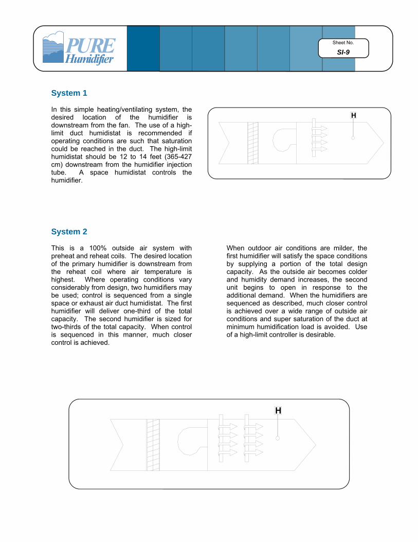
System 1 In this simple heating/ventilating system, the desired location of the humidifier is downstream from the fan. The use of a high-limit duct humidistat is recommended if operating conditions are such that saturation could be reached in the duct. The high-limit humidistat should be 12 to 14 feet (365-427 cm) downstream from the humidifier injection tube. A space humidistat controls the humidifier.
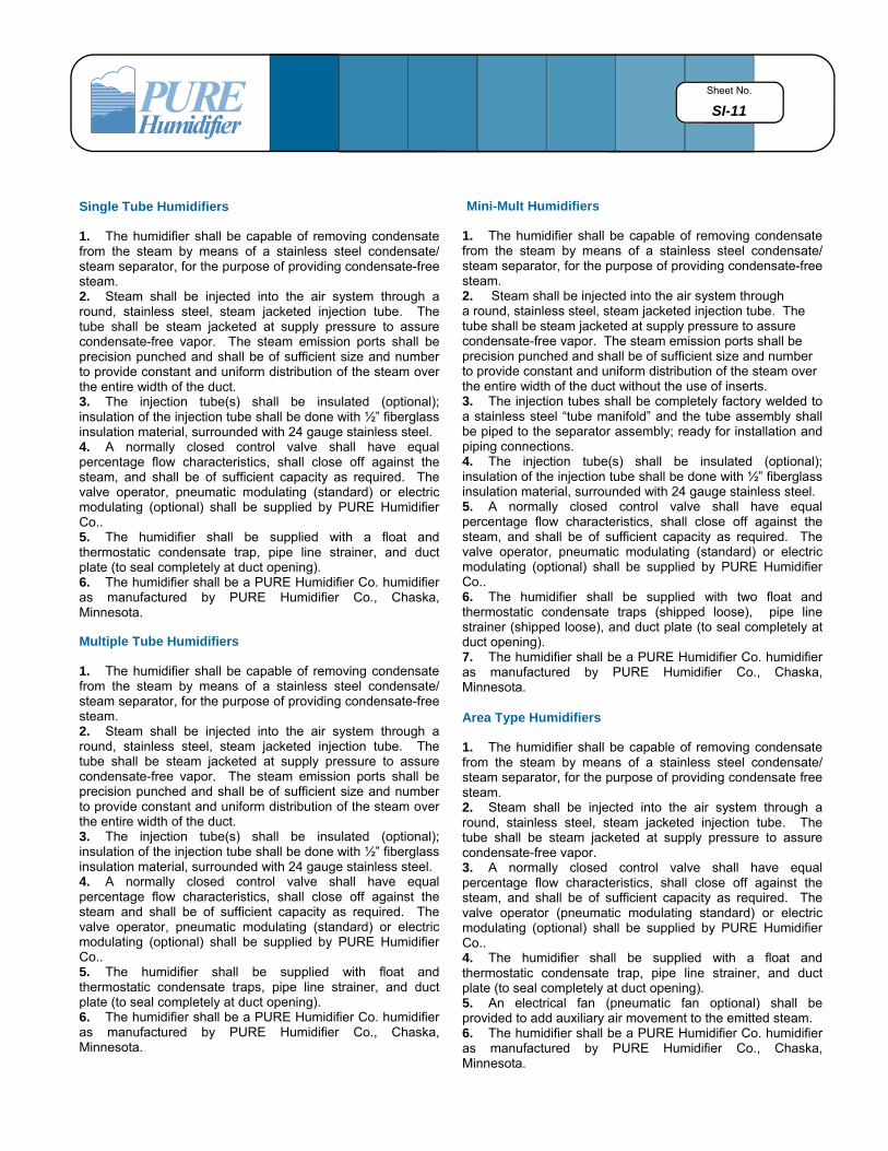
System 2 This is a 100% outside air system with preheat and reheat coils. The desired location of the primary humidifier is downstream from the reheat coil where air temperature is highest. Where operating conditions vary considerably from design, two humidifiers may be used; control is sequenced from a single space or exhaust air duct humidistat. The first humidifier will deliver one-third of the total capacity. The second humidifier is sized for two-thirds of the total capacity. When control is sequenced in this manner, much closer control is achieved.
When outdoor air conditions are milder, the first humidifier will satisfy the space conditions by supplying a portion of the total design capacity. As the outside air becomes colder and humidity demand increases, the second unit begins to open in response to the additional demand. When the humidifiers are sequenced as described, much closer control is achieved over a wide range of outside air conditions and super saturation of the duct at minimum humidification load is avoided. Use of a high-limit controller is desirable.
H
H

Sheet No.
SI-10
System 3 Shown here is a 100% outside air system using a primary and secondary humidifier. In this system, the primary humidifier is controlled by a duct humidistat 12 to 14 feet (366-427 cm) downstream from the humidifier and at a level that maintains a space condition of about 35% R.H. at 70°F. The secondary humidifier is controlled by a space humidistat. The secondary unit can be sized to boost space R.H. from 35% R.H. to a higher level such as 55% R.H. Combining humidifiers in this manner allows humidity for each zone to be controlled at a level higher than would otherwise be possible.
System 4 This is a high velocity, dual duct system. In this system, best results are achieved with primary and booster humidification. The primary humidifier is located as far upstream as possible from the fan and is controlled by a duct humidistat located ahead of the hot and cold deck coils. The booster humidifier is located downstream from the mixing box and is controlled by a humidistat in the space. The primary humidifier should be located no closer than 3 feet (91 cm) from the fan and the booster humidifier no closer than 3 feet (91 cm) from the grill. In both cases, the use of multiple injection tube units should be considered.
System 5 System 5 is a simple face and bypass unit. The humidifier is located downstream from the damper section so moisture enters the air stream in the area where best mixing and air temperature conditions exist.
H
HCOOLI
NG
HEATING
MIXING BOX
Sheet No.
SI-11
Single Tube Humidifiers
1. The humidifier shall be capable of removing condensate from the steam by means of a stainless steel condensate/steam separator, for the purpose of providing condensate-free steam. 2. Steam shall be injected into the air system through a round, stainless steel, steam jacketed injection tube. The tube shall be steam jacketed at supply pressure to assure condensate-free vapor. The steam emission ports shall be precision punched and shall be of sufficient size and number to provide constant and uniform distribution of the steam over the entire width of the duct. 3. The injection tube(s) shall be insulated (optional); insulation of the injection tube shall be done with ½” fiberglass insulation material, surrounded with 24 gauge stainless steel. 4. A normally closed control valve shall have equal percentage flow characteristics, shall close off against the steam, and shall be of sufficient capacity as required. The valve operator, pneumatic modulating (standard) or electric modulating (optional) shall be supplied by PURE Humidifier Co.. 5. The humidifier shall be supplied with a float and thermostatic condensate trap, pipe line strainer, and duct plate (to seal completely at duct opening). 6. The humidifier shall be a PURE Humidifier Co. humidifier as manufactured by PURE Humidifier Co., Chaska, Minnesota. Multiple Tube Humidifiers
1. The humidifier shall be capable of removing condensate from the steam by means of a stainless steel condensate/steam separator, for the purpose of providing condensate-free steam. 2. Steam shall be injected into the air system through a round, stainless steel, steam jacketed injection tube. The tube shall be steam jacketed at supply pressure to assure condensate-free vapor. The steam emission ports shall be precision punched and shall be of sufficient size and number to provide constant and uniform distribution of the steam over the entire width of the duct. 3. The injection tube(s) shall be insulated (optional); insulation of the injection tube shall be done with ½” fiberglass insulation material, surrounded with 24 gauge stainless steel. 4. A normally closed control valve shall have equal percentage flow characteristics, shall close off against the steam and shall be of sufficient capacity as required. The valve operator, pneumatic modulating (standard) or electric modulating (optional) shall be supplied by PURE Humidifier Co.. 5. The humidifier shall be supplied with float and thermostatic condensate traps, pipe line strainer, and duct plate (to seal completely at duct opening). 6. The humidifier shall be a PURE Humidifier Co. humidifier as manufactured by PURE Humidifier Co., Chaska, Minnesota.
Mini-Mult Humidifiers
1. The humidifier shall be capable of removing condensate from the steam by means of a stainless steel condensate/steam separator, for the purpose of providing condensate-free steam. 2. Steam shall be injected into the air system through a round, stainless steel, steam jacketed injection tube. The tube shall be steam jacketed at supply pressure to assure condensate-free vapor. The steam emission ports shall be precision punched and shall be of sufficient size and number to provide constant and uniform distribution of the steam over the entire width of the duct without the use of inserts. 3. The injection tubes shall be completely factory welded to a stainless steel “tube manifold” and the tube assembly shall be piped to the separator assembly; ready for installation and piping connections. 4. The injection tube(s) shall be insulated (optional); insulation of the injection tube shall be done with ½” fiberglass insulation material, surrounded with 24 gauge stainless steel. 5. A normally closed control valve shall have equal percentage flow characteristics, shall close off against the steam, and shall be of sufficient capacity as required. The valve operator, pneumatic modulating (standard) or electric modulating (optional) shall be supplied by PURE Humidifier Co.. 6. The humidifier shall be supplied with two float and thermostatic condensate traps (shipped loose), pipe line strainer (shipped loose), and duct plate (to seal completely at duct opening). 7. The humidifier shall be a PURE Humidifier Co. humidifier as manufactured by PURE Humidifier Co., Chaska, Minnesota. Area Type Humidifiers
1. The humidifier shall be capable of removing condensate from the steam by means of a stainless steel condensate/steam separator, for the purpose of providing condensate free steam. 2. Steam shall be injected into the air system through a round, stainless steel, steam jacketed injection tube. The tube shall be steam jacketed at supply pressure to assure condensate-free vapor. 3. A normally closed control valve shall have equal percentage flow characteristics, shall close off against the steam, and shall be of sufficient capacity as required. The valve operator (pneumatic modulating standard) or electric modulating (optional) shall be supplied by PURE Humidifier Co.. 4. The humidifier shall be supplied with a float and thermostatic condensate trap, pipe line strainer, and duct plate (to seal completely at duct opening). 5. An electrical fan (pneumatic fan optional) shall be provided to add auxiliary air movement to the emitted steam. 6. The humidifier shall be a PURE Humidifier Co. humidifier as manufactured by PURE Humidifier Co., Chaska, Minnesota.

Sheet No.
SI-12
Condensate Return Line
In order for the steam trap to remove condensate, it is essential that pressure in the condensate return line be substantially below the steam’s supply pressure. In the event the return line is at a higher elevation than the steam trap, the trap should be drained to a floor drain or the condensate must be elevated. In elevating condensate, an intermittent discharge trap, such as an inverted bucket type, should be used. Every 2 psi (13.8 kpa) of steam pressure will elevate the condensate one foot (30.5 cm). Also, a check valve must be installed on the outlet of the steam trap to prevent back flow of the elevated condensate into the humidifier. Expanded Duct Section
To avoid restricting air flow in a duct 8 inches (20.3cm) or less in height, use of an expanded duct section is recommended. Proper Length Injection Tubes For best dissipation of the steam into the air stream, always use injection tubes that fully span the widest dimension of the duct. Vertical Tube Humidifiers In those installations where the duct is taller than it is wide, a vertical tube humidifier may be used to gain tube length. NOTE: Vertical tube humidifiers must always be installed with the tube(s) pointing upwards to avoid trapping condensate in the outboard end of the injection tube. Insulated Injection Tubes Where specifications require, insulated injection tubes are available. The insulation is 1/2” (1.3 cm) fiberglass covered with a 24 gauge stainless steel jacket. NOTE: Insulated injection tubes must be installed with the stream emitting with the air flow to prevent condensation on the outer insulation jacket.
Fan Interlock Switch
PURE Humidifier Co. recommends the use of an air flow proving switch or fan interlock to prove air flow prior to humidifier operation. Humidifier operation without air flow will result in over-saturation of the air stream. Air flow proving switches are available as optional equipment from your PURE Humidifier Co. representative. High-Limit Humidistat
PURE Humidifier Co. recommends the use of a duct high-limit humidistat to prevent humidifier operation when the duct humidity level exceeds 85% relative humidity. Humidifier operation above 85% relative humidity can result in over saturation of the air stream. High-limit humidistats are available as optional equipment from your PURE Humidifier Co. representative. Temperature Interlock Switch PURE Humidifier Co. recommends the use of an Interlock temperature switch on applications with steam pressures below 5 psi (34.5 kpa) or as a safety switch to prevent humidifier operation in the case of a boiler or trap malfunction. Interlock temperature switches (pneumatic or electric) are available as optional equipment from your PURE Humidifier Co. representative. Location of Humidifiers Humidifiers should be located: 1. In the center of duct or air handling unit. 2. Not less than 3 feet (91.4 cm) upstream from fan
inlets, tees, “ells”, turning vanes, discharge grills or other in-duct objects.
3. Not less than 10 feet (304.8 cm) upstream from high efficiency filters.
4. Not less than 10 feet (304.8 cm) upstream from humidity or temperature controllers.