
Status Report IMSR-400 - ARIS · Status Report – IMSR-400 Overview Full name Integral Molten Salt...
15
Status Rep ort – IMSR-400 Ove r view Full name Integral Molten Salt Reactor-400 Ac ronym IMSR-400 Reactor type Molten Salt Reactor Purpose Commercial Coolant Fluoride Salts Moderator Graphite Neutron Spectrum Thermal Thermal capacity 400 MW per module Electrical capacity 194 MW per module Design status Under design Designe rs Terrestrial Energy Last update July 28, 2016
Transcript of Status Report IMSR-400 - ARIS · Status Report – IMSR-400 Overview Full name Integral Molten Salt...

Status Report – IMSR-400
Overview
Full name Integral Molten Salt Reactor-400
Acronym IMSR-400
Reactor type Molten Salt Reactor
Purpose Commercial
Coolant Fluoride Salts
Moderator Graphite
Neutron
Spectrum
Thermal
Thermal capacity 400 MW per module
Electrical capacity 194 MW per module
Design status Under design
Designers Terrestrial Energy
Last update July 28, 2016

1. Introduction The Integral Molten Salt Reactor – 400 Megawatts-thermal (IMSR400) is a small modular molten salt fuelled reactor. It features a completely sealed reactor vessel with integrated pumps, heat exchangers and shutdown rods. This vessel, called the IMSR core-unit, is replaced completely as a single unit at the end of its useful service life (nominally 7 years). This allows factory production levels of quality control and economy, while avoiding any need to open and service the reactor vessel at the power plant site.
IMSR400 main heat transport path for power generation The IMSR uses molten fluoride salt, a highly stable, inert liquid with robust coolant properties and high intrinsic radionuclide retention properties, for its primary fuel salt. A secondary, coolant salt loop, also using a fluoride salt (but without fuel), transfers heat away from the primary heat exchangers integrated inside the core-unit. As shown in the figure above, the coolant salt loop, in turn, transfers its heat load to a solar salt loop, which is pumped out of the nuclear island to a separate building where it either heats steam generators that generate superheated steam for power generation or is used for process heat applications. The design is based heavily on the intensive molten salt reactor project of Oak Ridge National Laboratory (ORNL) in the 1950’s - 1970’s. In this project, extensive R&D was done and molten salt reactor materials and equipment were developed. This included such items as suitable graphite to act as neutron moderator, drain tanks for the salts, hot cells for housing the equipment, pumps and heat exchangers. The ORNL program culminated in the construction and successful operation of the Molten Salt Reactor Experiment (MSRE). The MSRE employed a molten fluoride fuel salt, which was also the primary coolant. This fuel-coolant mixture was circulated between a critical graphite moderated core and external heat exchangers. The IMSR is essentially a re-configured, scaled-up version of the MSRE. This minimizes required research and development (R&D). The IMSR has also been influenced by a more recent ORNL design, the small modular advanced high temperature reactor (SmAHTR) which was to use solid fuel with fluoride salt coolant, but had an “integral”
architecture where all primary pumps, heat exchangers and control rods are integrated inside the sealed reactor vessel. The safety philosophy behind the IMSR is to produce a nuclear power plant with gen-IV reactor levels of safety. For ultimate safety, there is no dependence on operator intervention, powered mechanical components, coolant injection or their support systems such as electricity supply or instrument air in dealing with upset conditions. This is achieved through a combination of design features:
The inert, stable properties of the salt;
An inherently stable nuclear core;
Fully passive backup core and containment cooling systems.
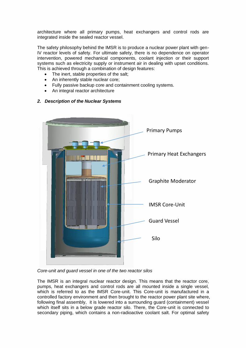
An integral reactor architecture 2. Description of the Nuclear Systems
Core-unit and guard vessel in one of the two reactor silos
The IMSR is an integral nuclear reactor design. This means that the reactor core, pumps, heat exchangers and control rods are all mounted inside a single vessel, which is referred to as the IMSR Core-unit. This Core-unit is manufactured in a controlled factory environment and then brought to the reactor power plant site where, following final assembly, it is lowered into a surrounding guard (containment) vessel which itself sits in a below grade reactor silo. There, the Core-unit is connected to secondary piping, which contains a non-radioactive coolant salt. For optimal safety
Primary Pumps
Primary Heat Exchangers
Graphite Moderator
IMSR Core-Unit
Guard Vessel
Silo

and containment, this coolant salt is used as an inert, low pressure intermediate loop between the critical reactor circuit and the steam power generation circuit. The steam circuit powers a conventional, off-the-shelf industrial steam turbine for power generation and/or industrial steam production, depending on the required application. Alternately, some or all of the hot molten salt may be sent directly to a process heat application. Being a liquid fuel reactor, there are no fuel elements in the reactor core. The fuel may consist of low enriched uranium fluoride, plutonium fluoride, thorium fluoride, or any mixture of these. The first of a kind IMSR400 however, will utilize a once-through, low enriched uranium fuel cycle as this is the simplest option. This fuel salt is diluted with coolant salt, consisting of fluorides such as sodium fluoride, beryllium fluoride and/or lithium fluoride. Together this mixture constitutes both fuel and primary coolant. The fuel-coolant mixture is pumped between a critical, graphite moderated (thermal spectrum) core, and then through the integral heat exchangers to transfer its heat to the secondary, coolant salt loop. The latter loop consists of bare diluent salts (without fuel salt added), that in turn transfers its heat to another intermediate salt loop. This second intermediate salt loop or “third loop” improves safety by adding another barrier between the radioactive primary inventory and the steam turbine. This third loop uses a nitrate salt, for its lower melting point (to avoid steam generator freezing) and compatibility with steam (in the event of a leak). Finally, the nitrate salt heated steam generator produces steam for process heat or to power a steam turbine-generator set. This fuel is separately brought to the power plant site as a solid, where it is melted and added to the IMSR Core-unit. This allows the IMSR to operate with online fuelling. Additionally, and unlike solid-fuel reactors, there is no need to remove a proportion of old fuel during makeup fuelling. All of the fuel stays inside the closed IMSR Core-unit during the entire power operations period of the Core-unit. The volume of small amounts of additional “Makeup” fuel salt is simply accommodated in the upper gas plenum. Unlike other power reactor systems, the IMSR Core-unit needs never be opened at the power plant site, either during start-up fuelling or during refuelling. After ~7 years of power operation, the Core-unit is shut down and after a cool-down period, the used fuel charge is pumped out to robust holding tanks located inside the containment. The spent, empty Core-unit is then allowed to cool down for several more years, at which point its radioactivity has diminished sufficiently to permit its safe removal from its containment silo. The IMSR400 is a single unit plant, however two Core-unit silos are used, to allow switch-loading of the silos: this allows a long period of cool-down for the spent silo, while another is connected by switching over the secondary, coolant salt lines to the new unit. After this long cool-down period, the spent, empty Core-unit is then moved into a long-term storage silo where it can stay for an extended period. Beyond this period the Core-unit can be shipped to a central facility, to be recycled or prepared for geological sequestration. Similarly the separately stored spent fuel charge can also be shipped to a central facility to recover the fuel or for conversion to a form for sequestration. This sealed, integral reactor architecture and once-through, “burner” fuel cycle mode allows the actual power plant site to always operate in a clean, simple environment without risk of facility contamination.

Cut-away view into the reactor auxiliary building.
3. Description of Safety concept All nuclear power reactors must fulfil three fundamental safety requirements: the chain reaction must be controlled, sufficient cooling must be provided to transfer heat out of the reactor core, and the radioactive materials must be contained inside the plant. The basic design approach to safety in the IMSR is to achieve an inherent, walk-away safe nuclear plant. No operator action, electricity, or externally-powered mechanical components are needed to assure the most basic safety functions:
- Control: failure of control systems or reactivity insertion events only leads to
reactor stabilization at a slightly higher temperature. - Cool: inherent heat sinks are available initially to absorb transient and decay
heat, with heat losses providing long term cooling for both core and containment.
- Contain: the fluoride salts are chemically stable, bind radioactive fission
products to the salt, and have extremely high boiling points. Multiple engineered barriers are provided as backup to this inherent containment. Partial entrenchment of the reactor, combined with thick concrete and steel shielding, provides resistance to external events such as earthquakes, explosions, and aircraft crash.
An important part of the IMSR safety philosophy is to start by removing drivers that push radioactive material into the environment. Specifically the reactor always operates at low pressure due to the inert, low-volatile fuel-coolant mixture and the absence of water or steam in the reactor. As the materials employed in the reactor system and even the interfacing systems, are all chemically compatible with each other, there is no potential for adverse chemical reactions such as fuel cladding hydrogen production or sodium reactions with air or water. This approach completely eliminates stored energy, both physical and chemical, from the reactor system. The IMSR further augments this high level of inherent, physics-based safety with its

integrated, pipe-less, fail-safe systems architecture. The result is a simple and robust system with inherent safety. In light water reactors (LWRs) the safety concept is dependent on providing sufficient coolant flow to the solid fuel assemblies at all times. This must occur at high pressure. During loss of coolant (LOCA) accidents such as pipe leaks or breaks, reliable depressurization is required, followed by low-pressure coolant injection. These systems require various mechanical, electrical/control systems, instrumentation/sensing, instrument air and other support systems to operate reliably. The IMSR does not depend on depressurizing the reactor or bringing coolant to the reactor. All required control and heat sink functions are already present where they are needed – in and directly around the IMSR Core-unit. As such the IMSR completely eliminates any dependence on support systems, valves, pumps, and operator actions. This is the case in both the short term and the long term. To make this possible, the IMSR designers have combined molten salt reactor technology with integral reactor design and a unique cooling system. Reactor criticality control is assured through a negative temperature feedback made possible by molten salt fuel. This negative temperature feedback assures reactor safety on overheating, even with loss of all control systems. Molten salt fuel does not degrade by heat or radiation, so there are effectively no reactor power limits to the fuel. The unique cooling system is based on heat capacity and heat loss – which are immutable. Heat capacity is due to the thermal mass of the fuel salt, vessel metal, and graphite. Heat loss occurs as the reactor vessel is not insulated. Short term cooling is provided by the low power density Core-unit, and the internal natural circulation capability of the fluoride fuel salt, resulting in a large capacity to absorb transient and decay heat generation. Longer term cooling is provided by heat loss from the uninsulated reactor vessel which itself is enveloped by a guard vessel. This guard vessel is a closed vessel that envelops the Core-unit, providing containment and cooling through its vessel wall. Overheating of the Core-unit will cause the Core-unit to heat up and increase heat loss from the core-unit, in turn increasing heat transfer, via thermal radiation, to the guard vessel. The guard vessel in turn is surrounded by a robust air cooling jacket. This cooling jacket will provide long term cooling. The cooling jacket operates at atmospheric pressure so will continue to cool in the event of a leak or damage to the jacket. The guard vessel containment is provided as an additional hermetic barrier in the extremely unlikely event that the integral Core-unit itself would experience major failures. Without sources of pressure in the Core-unit or in the containment itself, the containment is never challenged by pressure. Overheating of the containment is precluded by the balance of heat losses and heat generation even if the Core-unit would fail. The containment itself is covered by thick horizontal steel radiation shield plates at the top. These plates also provide protection against extreme external events such as aircraft crash or explosion pressure waves, and provide an additional heat sink in any overheating scenario.

The Core-unit loses heat to an enveloping guard vessel, which in turn loses heat to a passive air cooling jacket. This provides backup cooling in the unlikely event all of the redundant normal heat exchangers are unavailable for any reason.
The IMSR has a highly attractive seismic profile due to its compact, integral (pipe-less) primary system. In addition, the below grade silo housing the Core-unit, and low profile buildings, result in a very low centre of gravity. Apart from the reactor system and buildings themselves, earthquakes can often threaten support systems such as main power, backup power, battery power, instrumentation and control systems, emergency coolant injection lines, or pneumatic and hydraulic systems. As the IMSR does not rely on any of these support systems, or even the cooling jacket for ultimate safety, the IMSR’s safety is inherently insensitive to earthquakes. The IMSR system is a high temperature reactor system whose key safety systems are designed for extreme normal and emergency temperature profiles. No support systems are required for safe shutdown. As a result of these features, the design is inherently insensitive to fires from a safety viewpoint. As explained above, ultimate safety is provided by inherent and fail-safe features. Nevertheless, with a view of further improving the robustness of the design, to improve the reliability, and as investment protection, a considerable amount of defence-in-depth is built-in the systems. For the control function, redundant, shutdown rods are also integrated into the IMSR Core-unit. These shutdown rods will shut down the reactor upon loss of forced circulation and will also insert upon loss of power. Another backup is provided in the form of meltable cans, filled with a liquid neutron absorbing material that will shut down the reactor on overheating. A complete loss of flow is however itself unlikely, as redundant primary pumps are used for circulating the fuel salt, so that the system can continue to operate at full power with any single pump failed or tripped, and slightly de-rated operation is possible with any two pumps failed or tripped. Similarly, to drive the pumps, conventional backup

engine-driven power is available upon loss of main power. For containment, in addition to the inherently stable salt properties that act as physical and chemical containment, the integrated reactor architecture maximizes the integrity of the primary reactor system, the Core-unit. This makes leaks very unlikely. Should any leaks occur, a conventional, leak-tight containment is also provided. Overpressure failure is not a plausible event due the very high boiling points of the salts and to a lack of pressurization sources inside the Core-unit and even in interfacing systems. Overheating failure of the Core-unit is precluded by the use of high quality, high temperature capable materials in conjunction with the inherent heat loss to the surrounding passive cooling jacket.
4. Proliferation Defences
The IMSR has intrinsic, design, and procedural features that resist proliferation of fissile materials for weapons production:
1. Fuel cycle: the IMSR Core-unit itself is fuelled with low enriched uranium on a once-through fuel cycle without fuel processing. There is no need for highly enriched uranium, and, with no fuel processing on-site, there is no possibility of separating fissile materials from the bulk of fuel salt. In addition, the high burn-up and lack of online fuel removal from the IMSR Core-unit results in extremely poor isotopic quality in the spent fuel inventory. In a molten salt reactor such as the IMSR, fuel and coolant are intrinsically mixed. Removal of any significant amount of fuel therefore entails the removal of much larger volumes of coolant salt. Any future fuel processing would be done in a secure, centralized facility.
2. Systems design: the plant engineering does not allow the removal of significant quantities of fuel salt to small, and thus mobile shielded containers during normal operation. Fuel is added to the Core-unit, fuel salt need not be removed during the seven year cycle. Minor transfers for chemistry monitoring and control or for final spent fuel salt transfer to large shielded holding tanks will be completely human-inaccessible due to the high temperature and radiation levels. Any future transfer of spent fuel salt for sequestration or processing will involve time-consuming protocols under full supervision. Such off site transfers would entail full self-protection due to activity levels of contained fission products.
3. Procedural controls: the IMSR will comply with all IAEA proliferation safeguards, procedural controls, monitoring and other requirements.
5. Safety and Security (physical protection)
The IMSR is a molten salt reactor, having a highly radioactive primary fuel-coolant loop. In addition, the high operating temperature means special shielded, insulated cells and systems will be employed. These features make the reactor design highly inaccessible to potential sabotage or terrorist attack. The IMSR also employs the integral architecture, which produces a compact, robust, and fully sealed primary core-heat exchanger unit. Another design feature that protects against external threats is the provision of a hardened below grade silo as the holding cell for the Core-unit. Such hardening and below grade construction provides superior protection against external events. The Core-unit itself is provided with additional layers of protection: a sealed guard vessel surrounding the bottom and sides of the Core-unit, and a steel containment plate at the top. This containment head plate is made of very

thick steel primarily for radiation shielding, which also makes for a high strength, ductile external events shield capable of stopping the impact of a large commercial aircraft crash or explosive devices. Because the IMSR does not rely on any support systems, any attack on such support systems does not impede any of the three primary safety functions – control, cooling and containment - of the IMSR.
6. Description of turbine-generator systems The turbine-generator system does not serve any safety related mission and is not needed for ultimate safe shutdown of the IMSR Core-unit. Therefore, the IMSR will employ a standard, off-the-shelf, industrial grade superheated steam turbine plant. The use of a standard turbine avoids the necessity of having to develop a new turbine and control system for the IMSR, and allows the highly flexible and reliable industrial grade steam turbines to be used, that can be sourced from a variety of major suppliers. These steam turbines are highly flexible, being capable of high degrees of bleed off steam for cogeneration/industrial heat purposes, whilst also being capable of operating as condensing (power generating) turbine-only if required. This affords the IMSR access to many industrial power and heat markets such as steam assisted gravity drainage (SAGD), chemicals production, paper and pulp production, desalination, etc. In fact, these turbines, powered by fossil fuel boilers, are widely used already in many such industries today. The turbine-generator is a simple and compact, high speed, skid mounted design. A gearbox couples the high-speed turbine to a lower speed, 1500 to 1800 RPM electrical generator.
7. Electrical and I&C systems The IMSR does not depend on electrical or even I&C systems for ultimate safety. For operability and investment protection, a few additional requirements do exist, such as freeze protection, as the fluoride salts have high freezing points. The normal plant operations systems provide this protection, in the form of pump trips, electrical (trace) heating, and thermocouple sensors. As with the steam turbine-generator, this type of equipment is available off-the-shelf from many suppliers. The pumps are the primary control units, as passive, flow driven control rods are utilized. This links the trip and protection logic to the pump rather than to a control rod drive and logic system. The result is a simple and easy to control system where the only real variable to control actively is the pump speed (trace heating is typically kept in automatic mode for normal operations). For example, to rapidly shut down the reactor, no control rod drives, drive power, hydraulic supply, or other support systems are needed; instead the pumps are simply tripped. The simplicity of this approach and the lack of dependence on any electrical systems also means that cyber-security is easy to address. As the IMSR does not depend on the electrical systems for ultimate safety, the design of a detailed plant electrical and control room system is eased. However, as with the steam turbine-generator, standard, off-the-shelf industrial equipment is expected to be used due to the generic nature of the requirements.

8. Spent Fuel and Waste management
The IMSR utilizes nuclear fuel with far greater efficiency than light water reactors. There are three basic factors that improve the fuel utilization of the IMSR compared to light water reactors:
1. The thermal-to-electrical efficiency is high; despite the modest size, the IMSR400 features higher plant electrical efficiency than light water reactors. Depending on heat sink conditions and balance-of-plant arrangement, the IMSR400 generates 185 to 192 MWe from 400 MWth, resulting in a net efficiency of some 46-48%.
2. The fuel burn-up is high: rather than removing fuel from the reactor, new fuel is simply added to the total fuel charge forming the reactor core. The high burn-up and retention of fuel inside the core results in improved plutonium and minor actinide burning capability.
3. Without fuel cladding, internal metallic structures or H2O, and with the IMSR design permitting the passive exit of Xenon from the core, there are far fewer parasitic neutron captures.
An additional advantage of the design is that its spent liquid fuel inventory is much easier to recycle than solid fuel elements, making it more attractive to recycle the fuel. As the fuel does not degrade, it can potentially be recycled many times. If fuel recycling is employed, Terrestrial Energy envisages this to occur in a central fuel recycling centre, servicing many IMSR power plants.
The design also makes efficient use of engineering and construction materials. This is mostly due to the low operating pressure and lack of stored energy in the salts, eliminating the need for massive pressure vessels, pipe restraints, and containment buildings. High pressures are confined to the steam turbine plant, which is a very compact, standard industrial grade unit. The salts also have high volumetric heat capacity resulting in compact heat exchangers, pumps, and other heat transport equipment. The result is very compact equipment and small buildings.
The IMSR features a fully sealed unit, avoiding the need to open the reactor vessel during operation. This feature greatly reduces expected dose rates to personnel, and avoids generation of large amounts of contaminated drainage water and disposables.
9. Plant layout The IMSR Core-unit is housed in a below grade silo. This forms the heart of the IMSR system. Surrounding the Core-unit are the guard vessel cooling jacket, and at the top, a removable steel containment head plate. All these components are located below grade as well. Above the containment head, shield plates cover the Core-unit for radiation shielding. An idle silo is provided next to the active silo, so that this silo can be loaded with a new Core-unit while facilitating cool down of a spent Core-unit. These two silos make up the main components of the reactor building. After draining the spent Core-unit followed by a cool down period, the empty spent module is the lifted out and stored in long-term storage silos in an area adjacent to the reactor building. Inlets and outlets are provided for the (non radioactive) coolant salt lines coming into and out of the Core-unit, which transfer the heat to steam generators and re-heaters. The coolant salt lines are located inside the reactor building. The steam

and reheat steam are utilized in a conventional, off-the-shelf turbine-generator system located in an adjacent building.
IMSR400 plant layout
10. Plant Performance The IMSR plant is designed to accommodate various load users, from baseload to load-following. Featuring a simple modular and replaceable Core-unit, very high reliability ratings are targeted. The Core-unit has only a few moving parts (pumps) and these are redundantly fitted. Even premature replacement of a faulty module only mildly affects reliability and levelized cost. The use of an idling silo greatly increases plant capacity factor, as long cool down times (for radiation dose reduction) are possible without plant downtime. The IMSR has been specifically designed for factory fabrication. Nuclear components are small and road-transportable. The IMSR Core-unit is designed for a short service lifetime, which allows dedicated factory lines to produce the units semi-automatically, similar to aircraft jet engine production lines for example. The IMSR reactor building has a low profile and low mass, allowing rapid construction. The reactor building is a simple lightweight industrial building as it does not serve any major safety-related function - these are all provided by dedicated, robust, fail-safe systems. Being a molten salt reactor (MSR), the IMSR has low fuel reload costs; fuel fabrication costs are zero, only extensive purification of the salts is required which, being bulk chemical processing, has a much lower cost than traditional high precision fuel fabrication with all its quality and process control costs. Fuel recycling costs are also much lower with molten salt fuels, as costly fuel deconstruction and – reconstruction steps are avoided and also because simple, compact, low waste volume creating distillation and fluorination processes can be utilized. This makes it likely that spent IMSR fuel will be recycled.

11. Development status of technologies relevant to the NPP
The IMSR is a simplified burner-type molten salt reactor. All of the basic technology has been proven during the operation of the Molten Salt Reactor Experiment (MSRE) at Oak Ridge National Laboratories. The MSRE was a fully functional burner type MSR. Heat exchangers, pumps, suitable graphites, fuel salts and – purification steps, off-gas systems, fuel addition mechanisms, as well as alloys of construction were all successfully developed. The IMSR builds on this rich experimental evidence to assure a high degree of technological maturity. The IMSR utilizes an off-the-shelf industrial grade steam turbine-generator. Molten salt heated steam generators are also proven technology, with recent and very successful experience in advanced, large scale, salt-cooled Concentrated Solar Power (CSP) projects. Similarly water-cooled silo liners have been successfully employed in many nuclear reactor systems. Other technologies, such as tritium capture and management, are also proven technologies in the nuclear industry with a wide and current experience base in heavy water reactors as well as high temperature reactors. There are only a few components that have not been used before, such as the air cooling jacket. These components are technologically simple and their proper function will be verified in large scale non-nuclear testing.
12. Deployment status and planned schedule This phase of work involves the support of a growing number of universities, third party laboratories and industrial partners. In addition, the Canadian nuclear regulator, the Canadian Nuclear Safety Commission, at the request of TEI, has started Phase 1 of a pre-licensing Vendor Design Review of the IMSR. This is an assessment of a nuclear power plant design based on a vendor's reactor technology. The assessment is completed by the CNSC, at the request of the vendor. The words “pre-licensing” signifies that a design review is undertaken prior to the submission of a licence application to the CNSC by an applicant seeking to build and operate a new nuclear power plant. This review does not certify a reactor design or involve the issuance of a licence under the Nuclear Safety and Control Act, and it is not required as part of the licensing process for a new nuclear power plant. The basic engineering phase will be followed by the construction and start-up of a first full-scale commercial IMSR NNP at a site in Canada after securing all necessary operating licenses from the CNSC (and licenses from other authorities), a process that can be completed by early in the next decade.
13. References Terrestrial Energy website: www.terrestrialenergy.com World Nuclear article on Molten Salt Reactors: http://www.world-nuclear.org/info/Current-and-Future-Generation/Molten-Salt-Reactors/
Presentation by Terrestrial Energy CTO David Leblanc:
http://www.janleenkloosterman.nl/reports/kivi_leblanc_20150417.pdf
Oak Ridge Denatured Molten Salt Reactor work:
http://web.ornl.gov/info/reports/1980/3445603575931.pdf
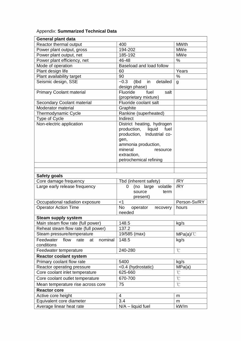
Appendix: Summarized Technical Data
General plant data
Reactor thermal output 400 MWth
Power plant output, gross 194-202 MWe
Power plant output, net 185-192 MWe
Power plant efficiency, net 46-48 %
Mode of operation Baseload and load follow
Plant design life 60 Years
Plant availability target 90 %
Seismic design, SSE ~0.3 (tbd in detailed design phase)
g
Primary Coolant material Fluoride fuel salt (proprietary mixture)
Secondary Coolant material Fluoride coolant salt
Moderator material Graphite
Thermodynamic Cycle Rankine (superheated)
Type of Cycle Indirect
Non-electric application District heating, hydrogen production, liquid fuel production, Industrial co-gen, ammonia production, mineral resource extraction, petrochemical refining
Safety goals
Core damage frequency Tbd (inherent safety) /RY
Large early release frequency 0 (no large volatile source term present)
/RY
Occupational radiation exposure <1 Person-Sv/RY
Operator Action Time No operator recovery needed
hours
Steam supply system
Main steam flow rate (full power) 148.5 kg/s
Reheat steam flow rate (full power) 137.2
Steam pressure/temperature 19/585 (max) MPa(a)/℃
Feedwater flow rate at nominal conditions
148.5 kg/s
Feedwater temperature 240-280 ℃
Reactor coolant system
Primary coolant flow rate 5400 kg/s
Reactor operating pressure <0.4 (hydrostatic) MPa(a)
Core coolant inlet temperature 625-660 ℃
Core coolant outlet temperature 670-700 ℃
Mean temperature rise across core 75 ℃
Reactor core
Active core height 4 m
Equivalent core diameter 3.4 m
Average linear heat rate N/A – liquid fuel kW/m

Average fuel power density Depends on fuel mixture kW/kgU
Average core power density 11-15 MW/m3
Fuel material UF4 in diluent fluorides (proprietary mixtures)
Cladding tube material No cladding employed – fluid fuel reactor
Outer diameter of fuel rods N/A – liquid fuel mm
Rod array of a fuel assembly N/A – liquid fuel
Number of fuel assemblies N/A – liquid fuel
Enrichment of reload fuel at equilibrium core
2-3% for start-up, 5-19% makeup fuel
Wt%
Fuel cycle length 84 months
Average discharge burnup of fuel 26-29 MWd/kg
Burnable absorber (strategy/material) None-online fuelling
Control rod absorber material N/A – no control rods
Shutdown rod absorber material Gadolinium oxide
Soluble neutron absorber None-online fuel makeup
Reactor pressure vessel
Inner diameter of cylindrical shell 3500 mm
Wall thickness of cylindrical shell 50 mm
Total height, inside 7000 mm
Base material SS316H or Alloy N
Design pressure/temperature 0.5/700 MPa(a)/℃
Transport weight 170 t
Steam generator (if applicable)
Type Tube-and-shell
Number 2
Total tube outside surface area 1400 m2
Number of heat exchanger tubes 10000
Tube outside diameter 12 mm
Tube material Incolloy 800H
Transport weight TBD t
Reactor coolant pump (if applicable)
Type Vertical, single stage, overhung, propeller pump
Number 6
Head at rated conditions 1.5 bar
Flow at rated conditions 0.27 m3/s/pump
Pump speed Variable speed drive rpm Pressurizer (if applicable)
Total volume - (low pressure) m3
Steam volume: full power/zero power - (low pressure) m3
Heating power of heater rods - (low pressure) kW
Primary containment
Type Metal, dry, low pressure
Overall form (spherical/cylindrical) Cylindrical silos and rectangular shielded vault
Dimensions (diameter/height) 4/9 m
Design pressure/temperature Atmospheric kPa(a)/℃
Design leakage rate 0.5 Vol%/day
Is secondary containment provided? Yes (reactor building)
Residual heat removal systems
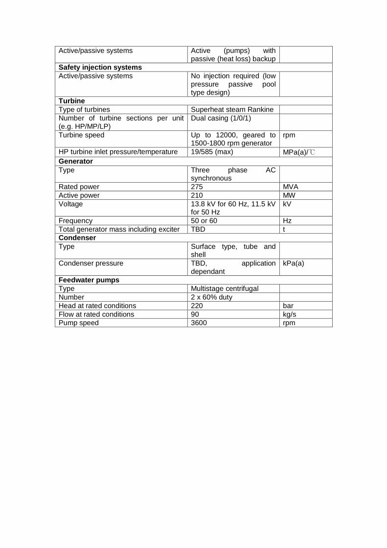
Active/passive systems Active (pumps) with passive (heat loss) backup
Safety injection systems
Active/passive systems No injection required (low pressure passive pool type design)
Turbine
Type of turbines Superheat steam Rankine
Number of turbine sections per unit (e.g. HP/MP/LP)
Dual casing (1/0/1)
Turbine speed Up to 12000, geared to 1500-1800 rpm generator
rpm
HP turbine inlet pressure/temperature 19/585 (max) MPa(a)/℃
Generator
Type Three phase AC synchronous
Rated power 275 MVA
Active power 210 MW
Voltage 13.8 kV for 60 Hz, 11.5 kV for 50 Hz
kV
Frequency 50 or 60 Hz
Total generator mass including exciter TBD t
Condenser
Type Surface type, tube and shell
Condenser pressure TBD, application dependant
kPa(a)
Feedwater pumps
Type Multistage centrifugal
Number 2 x 60% duty
Head at rated conditions 220 bar
Flow at rated conditions 90 kg/s
Pump speed 3600 rpm