Modelling of a 400-kV MSCDN Reactor for Computation of ...
9
Received May 16, 2018, accepted June 12, 2018, date of publication June 25, 2018, date of current version July 19, 2018. Digital Object Identifier 10.1109/ACCESS.2018.2849929 Modelling of a 400-kV MSCDN Reactor for Computation of Voltage and Field Distributions During Switching Transients HAZIAH ABDUL HAMID 1 , (Member, IEEE), NOUREDDINE HARID 2 , (Member, IEEE), MANU A. HADDAD 3 , (Member, IEEE), AND HUW GRIFFITHS 2 , (Member, IEEE) 1 School of Electrical Systems Engineering, Universiti Malaysia Perlis, Pauh Putra Campus, Arau 02600, Malaysia 2 Department of Electrical and Computer Engineering, Khalifa University of Science and Technology, Abu Dhabi 2533, United Arab Emirates 3 School of Engineering, Cardiff University, Cardiff CF24 3AA, U.K. Corresponding author: Noureddine Harid ([email protected]) ABSTRACT In this paper, a model for the reactor of a 400-kV mechanically switched capacitor with damping network (MSCDN) based on an equivalent circuit representation is developed. The model is based on sub-dividing the physical reactor into sections which are sufficiently small to be represented by a lumped- parameter equivalent circuit. The circuit parameters are obtained for each section using analytical formulae based on the physical configuration of the reactor, the winding layout, and the insulation material. The model is then simulated in the ATP/EMTP program for the evaluation of transient voltage and field distributions along of the reactor. This helps in identifying possible failure scenarios which will allow designing measures to mitigate failures effectively during transients arising from switching operations. Further analysis of the results has revealed that there are substantial dielectric stresses imposed on the winding insulation that can be attributed to a combination of three factors. First, the surge arrester operation during the MSCDN energization, which causes steep voltage change at the reactor terminal. Second, the non-uniform voltage distribution, resulting in high stresses across the top inter-turn windings. Third, the rapid rate-of-change of voltage in the assumed worst-case reactor winding location. This is accompanied by a high dielectric (displacement) current through the inter-turn winding insulation. The results of this paper indicate that a synergistic effect of high electric field and high dielectric current occurring at worst energization, followed by the thermal effects of steady state operation may contribute to the failure of air-core reactors used on the 400-kV MSCDN. INDEX TERMS Reactor, mechanically-switched capacitor, equivalent circuit, transient overvoltage, ATP/EMTP. I. INTRODUCTION Mechanically-switched capacitors with damping net- work (MSCDN) offer various benefits for electrical power transmission systems, such as voltage control, reactive power control, improvement of system stability, prevention of volt- age instability, and reduction of system harmonics. Dur- ing service, the MSCDN is subject to frequent switching operations and system perturbations, which may expose its components to transient overvoltages and currents with high rate of rise and long duration [1]. Of these components, the filter reactor, which is of dry type air-core design, may be particularly vulnerable to multiple overvoltage stresses produced during energisation [2]. With steep wave front impulse voltages, the voltage distribution on the reactor is non-uniform. Studies have shown that turn-to-turn insulation failure at the HV end of the reactor is the most common problem encountered during their service operation [3]. Such a failure may cause short circuit of turn-to-turn insulation, which consequently damages the reactor due to excessive overvoltages. This problem may occur if the applied electric field exceeds the dielectric strength of the insulation [4], [5]. Factors that influence the dielectric strength include the magnitude, shape, duration and polarity of the applied volt- age, the operating temperature, and other physical states of the insulation [6]. For solid dielectric materials, destructive stresses in electrical insulation systems are usually caused by one or any combination of electrical, mechanical, thermal, and environmental factors. VOLUME 6, 2018 2169-3536 2018 IEEE. Translations and content mining are permitted for academic research only. Personal use is also permitted, but republication/redistribution requires IEEE permission. See http://www.ieee.org/publications_standards/publications/rights/index.html for more information. 36247
Transcript of Modelling of a 400-kV MSCDN Reactor for Computation of ...
Received May 16, 2018, accepted June 12, 2018, date of publication June 25, 2018, date of current version July 19, 2018.
Digital Object Identifier 10.1109/ACCESS.2018.2849929
Modelling of a 400-kV MSCDN Reactor forComputation of Voltage and Field DistributionsDuring Switching TransientsHAZIAH ABDUL HAMID1, (Member, IEEE), NOUREDDINE HARID 2, (Member, IEEE),MANU A. HADDAD3, (Member, IEEE), AND HUW GRIFFITHS2, (Member, IEEE)1School of Electrical Systems Engineering, Universiti Malaysia Perlis, Pauh Putra Campus, Arau 02600, Malaysia2Department of Electrical and Computer Engineering, Khalifa University of Science and Technology, Abu Dhabi 2533, United Arab Emirates3School of Engineering, Cardiff University, Cardiff CF24 3AA, U.K.
Corresponding author: Noureddine Harid ([email protected])
ABSTRACT In this paper, a model for the reactor of a 400-kV mechanically switched capacitor withdamping network (MSCDN) based on an equivalent circuit representation is developed. The model is basedon sub-dividing the physical reactor into sections which are sufficiently small to be represented by a lumped-parameter equivalent circuit. The circuit parameters are obtained for each section using analytical formulaebased on the physical configuration of the reactor, the winding layout, and the insulation material. The modelis then simulated in the ATP/EMTP program for the evaluation of transient voltage and field distributionsalong of the reactor. This helps in identifying possible failure scenarios which will allow designing measuresto mitigate failures effectively during transients arising from switching operations. Further analysis of theresults has revealed that there are substantial dielectric stresses imposed on the winding insulation thatcan be attributed to a combination of three factors. First, the surge arrester operation during the MSCDNenergization, which causes steep voltage change at the reactor terminal. Second, the non-uniform voltagedistribution, resulting in high stresses across the top inter-turn windings. Third, the rapid rate-of-changeof voltage in the assumed worst-case reactor winding location. This is accompanied by a high dielectric(displacement) current through the inter-turn winding insulation. The results of this paper indicate that asynergistic effect of high electric field and high dielectric current occurring at worst energization, followedby the thermal effects of steady state operation may contribute to the failure of air-core reactors used onthe 400-kV MSCDN.
INDEX TERMS Reactor, mechanically-switched capacitor, equivalent circuit, transient overvoltage,ATP/EMTP.
I. INTRODUCTIONMechanically-switched capacitors with damping net-work (MSCDN) offer various benefits for electrical powertransmission systems, such as voltage control, reactive powercontrol, improvement of system stability, prevention of volt-age instability, and reduction of system harmonics. Dur-ing service, the MSCDN is subject to frequent switchingoperations and system perturbations, which may expose itscomponents to transient overvoltages and currents with highrate of rise and long duration [1]. Of these components,the filter reactor, which is of dry type air-core design, maybe particularly vulnerable to multiple overvoltage stressesproduced during energisation [2]. With steep wave frontimpulse voltages, the voltage distribution on the reactor is
non-uniform. Studies have shown that turn-to-turn insulationfailure at the HV end of the reactor is the most commonproblem encountered during their service operation [3]. Sucha failure may cause short circuit of turn-to-turn insulation,which consequently damages the reactor due to excessiveovervoltages. This problem may occur if the applied electricfield exceeds the dielectric strength of the insulation [4], [5].Factors that influence the dielectric strength include themagnitude, shape, duration and polarity of the applied volt-age, the operating temperature, and other physical states ofthe insulation [6]. For solid dielectric materials, destructivestresses in electrical insulation systems are usually caused byone or any combination of electrical, mechanical, thermal,and environmental factors.
VOLUME 6, 20182169-3536 2018 IEEE. Translations and content mining are permitted for academic research only.
Personal use is also permitted, but republication/redistribution requires IEEE permission.See http://www.ieee.org/publications_standards/publications/rights/index.html for more information.
36247
H. A. Hamid et al.: Modeling of a 400-kV MSCDN Reactor for Computation of Voltage and Field Distributions
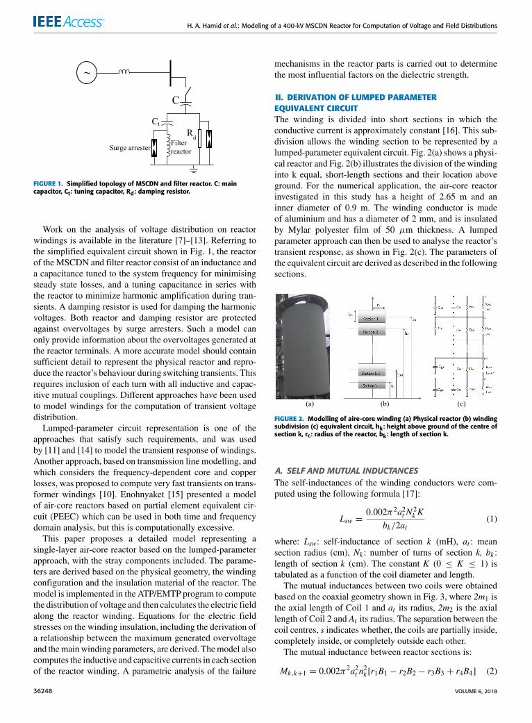
FIGURE 1. Simplified topology of MSCDN and filter reactor. C: maincapacitor, Ct: tuning capacitor, Rd: damping resistor.
Work on the analysis of voltage distribution on reactorwindings is available in the literature [7]–[13]. Referring tothe simplified equivalent circuit shown in Fig. 1, the reactorof the MSCDN and filter reactor consist of an inductance anda capacitance tuned to the system frequency for minimisingsteady state losses, and a tuning capacitance in series withthe reactor to minimize harmonic amplification during tran-sients. A damping resistor is used for damping the harmonicvoltages. Both reactor and damping resistor are protectedagainst overvoltages by surge arresters. Such a model canonly provide information about the overvoltages generated atthe reactor terminals. A more accurate model should containsufficient detail to represent the physical reactor and repro-duce the reactor’s behaviour during switching transients. Thisrequires inclusion of each turn with all inductive and capac-itive mutual couplings. Different approaches have been usedto model windings for the computation of transient voltagedistribution.
Lumped-parameter circuit representation is one of theapproaches that satisfy such requirements, and was usedby [11] and [14] to model the transient response of windings.Another approach, based on transmission line modelling, andwhich considers the frequency-dependent core and copperlosses, was proposed to compute very fast transients on trans-former windings [10]. Enohnyaket [15] presented a modelof air-core reactors based on partial element equivalent cir-cuit (PEEC) which can be used in both time and frequencydomain analysis, but this is computationally excessive.
This paper proposes a detailed model representing asingle-layer air-core reactor based on the lumped-parameterapproach, with the stray components included. The parame-ters are derived based on the physical geometry, the windingconfiguration and the insulation material of the reactor. Themodel is implemented in the ATP/EMTP program to computethe distribution of voltage and then calculates the electric fieldalong the reactor winding. Equations for the electric fieldstresses on the winding insulation, including the derivation ofa relationship between the maximum generated overvoltageand themainwinding parameters, are derived. Themodel alsocomputes the inductive and capacitive currents in each sectionof the reactor winding. A parametric analysis of the failure
mechanisms in the reactor parts is carried out to determinethe most influential factors on the dielectric strength.
II. DERIVATION OF LUMPED PARAMETEREQUIVALENT CIRCUITThe winding is divided into short sections in which theconductive current is approximately constant [16]. This sub-division allows the winding section to be represented by alumped-parameter equivalent circuit. Fig. 2(a) shows a physi-cal reactor and Fig. 2(b) illustrates the division of the windinginto k equal, short-length sections and their location aboveground. For the numerical application, the air-core reactorinvestigated in this study has a height of 2.65 m and aninner diameter of 0.9 m. The winding conductor is madeof aluminium and has a diameter of 2 mm, and is insulatedby Mylar polyester film of 50 µm thickness. A lumpedparameter approach can then be used to analyse the reactor’stransient response, as shown in Fig. 2(c). The parameters ofthe equivalent circuit are derived as described in the followingsections.
FIGURE 2. Modelling of aire-core winding (a) Physical reactor (b) windingsubdivision (c) equivalent circuit, hk: height above ground of the centre ofsection k, rc: radius of the reactor, bk: length of section k.
A. SELF AND MUTUAL INDUCTANCESThe self-inductances of the winding conductors were com-puted using the following formula [17]:
Lsw =0.002π2a2t N
2k K
bk/2at(1)
where: Lsw: self-inductance of section k (mH), at : meansection radius (cm), Nk : number of turns of section k, bk :length of section k (cm). The constant K (0 ≤ K ≤ 1) istabulated as a function of the coil diameter and length.
The mutual inductances between two coils were obtainedbased on the coaxial geometry shown in Fig. 3, where 2m1 isthe axial length of Coil 1 and at its radius, 2m2 is the axiallength of Coil 2 and At its radius. The separation between thecoil centres, s indicates whether, the coils are partially inside,completely inside, or completely outside each other.
The mutual inductance between reactor sections is:
Mk,k+1 = 0.002π2a2t n2k [r1B1 − r2B2 − r3B3 + r4B4] (2)
36248 VOLUME 6, 2018

H. A. Hamid et al.: Modeling of a 400-kV MSCDN Reactor for Computation of Voltage and Field Distributions
TABLE 1. Self and mutual inductances of winding sections (mH).
FIGURE 3. Basic geometry of two coaxial single-layer coils.
where Mk,k+1 mutual inductance between sections k andk + 1 (mH) and at the mean radius (cm), nk the winding den-sity (turns/cm), rn diagonal distances between sections (cm)and B the elliptic integral values.The four elliptic integrals, are functions of the following
four axial distances
x1 = s+ (m1 + m2)
x2 = s+ (m1 − m2)
x3 = s− (m1 − m2)
x4 = s− (m1 + m2) (3)
The diagonal distances between sections are given by
ri =√x2i + A
2t , i = 1..4 (4)
The elliptic integral values are tabulated as a function of thefollowing constants:
ρ2n =A2tr2n
(5)
α =atAt
(6)
The total inductance Lwk of section k is the sum ofits self-inductance and the mutual inductances due to allother sections. Table 1 summarizes the calculated self andmutual inductances for each section of the reactor windingfor k = 10. The diagonal elements of the table are the
self-inductance of each winding section. The off-diagonalelements are the mutual inductance between sections.
B. WINDING SERIES RESISTANCEThe series resistance Rwk represents the total winding ohmiclosses, the proximity effect, and the stray field losses causedby the large transverse magnetic field to which the con-ductors are subjected. Under impulse condition, the dielec-tric or shunt losses of the reactor are more dominant thanthe series losses; therefore, the latter can be adequately rep-resented by the ohmic losses of winding only. Assuminguniform current distribution across the winding cross-sectionand that the current remains constant at a dominant frequency,the series resistance of section k of the winding can beestimated as
Rwk =2Nkρcrcr2w
(7)
whereNk is the number of turns in section k , ρc the conductorresistivity, rc the section radius and rw the conductor radius.
C. INSULATION THICKNESSThe thickness of insulation in one turn layer (insulationbetween two successive turns of the winding) is assumed tobe equal to twice the thickness tm of the conductor insulatingmaterial. For a coil having N turns of conductors, the totalinsulation thickness in the coil is:
th = N × 2tm (8)
The height of each coil can then be obtained from:
hx = N (2tm + 2rw) (9)
from which we obtain:
th =hx
1+(rw/tm
) (10)
VOLUME 6, 2018 36249

H. A. Hamid et al.: Modeling of a 400-kV MSCDN Reactor for Computation of Voltage and Field Distributions
D. INTER-TURN INSULATION RESISTANCEThe current through the inter-turn insulation is composed ofthe capacitive current associated with field changes in thedielectric, the absorption current due to polarization effectsand the conduction or leakage current due to the actual elec-tronic conduction [18]. Leakage current represents the steadystate of the dielectric current that relies upon the appliedelectric field and temperature. The shunt resistance Rpk ofsection k of the inter-turn winding insulation is calculatedfrom:
Rpk =(Nk − 1) ρmtm
π2rcrw(11)
Where ρm is the resistivity of insulating material and tm itsthickness. The effective area is taken equal to half of the areaof the conductor surface of the inter-turn winding.
This resistance can also be calculated at a given frequency fif the dissipation factor (tanδ) of the insulation, and the inter-turn capacitance are known:
Rpk =Nk
2π fCtt tanδ(12)
where tanδ is the dissipation factor, f the dominant frequency,and Ctt the inter-turn capacitance.
E. INTER-TURN CAPACITANCEAssuming a small thickness of the insulation coatings, it ispossible to calculate the equivalent capacitance Ct,k of theseries connected inter-turn capacitances of section k byapproximating the conductor surfaces with a parallel-platehaving an effective area equal to half of the conductor cylin-drical surface:
Ctt,k =2π2ε0εmrcrm/tm
Nk − 1(13)
where ε0 is the permittivity of vacuum (F/m), and εm is therelative permittivity of the dielectric (F/m).
F. CAPACITANCE TO GROUNDThe stray capacitances-to-ground Cgk of each section can becalculated for a vertical cylinder [18] as:
Cgp = πεodc
[πdc2hk+ ln
(1+
bkhk
)](14)
where: dc is the conductor diameter, bk length of section kand hk distance from the centre of section k to ground.
III. MODEL IMPLEMENTATION IN ATP/EMTPFig. 4 shows the complete simulation circuit with a detailedmodel of the reactor added to the MSCDN network. To inves-tigate surge voltage distribution, the circuit breaker is speci-fied to close at the instant of voltage maximum, replicatingworst switching conditions. The computation time step is10 ns and the total simulation time is 10 ms. The closingtime of the switch representing the circuit breaker is specifiedat 2 ms, which was adjusted correspondingly to the time ofmaximum supply voltage. For the distribution of voltage and
FIGURE 4. ATP/EMTP simulation circuit for the MSCDN.
electric field at each reactor section, the maximum valuesare considered, and the results are reported in the followingsections.
FIGURE 5. Node voltage to ground (Vsec1 to Vsec8 indicate the computedvoltages at the 0%, 10%, 20% up to 70% along the winding away from thetop HV terminal).
IV. VOLTAGE DISTRIBUTION ALONG MSCDN REACTORA. DISTRIBUTION OF NODE TO GROUND VOLTAGEFig. 5 shows transient voltage-to-ground waveforms gener-ated at different locations on the reactor winding followingMSCDN energization. The voltage waveform Vsec1 is thevoltage-to-ground measured at the reactor terminal, whichreaches the highest magnitude of approximately 225 kV atan instant t = 5ns after switch closing. The actual steadystate reactor voltage is approximately 50 kV. The waveforms
36250 VOLUME 6, 2018

H. A. Hamid et al.: Modeling of a 400-kV MSCDN Reactor for Computation of Voltage and Field Distributions
Vsec2 to Vsec8 representing the node voltages occurring at10% to 70% of the reactor winding, have complex dampedoscillatory shapes of different oscillating frequencies. Thevoltage to ground along the winding length was also com-puted at time instants between 0.5 µs and 2 µs after switch-ing, with a time interval of 0.5 µs. The voltage distributionis non-uniform, as shown in Fig. 6, because of stray capaci-tances to both inter-turn and ground couplings. At the start ofthe transient, the highest stresses were observed at the top ofthe winding. As the impulse propagates along the winding,the voltage is redistributed towards the middle of the coiland away from the top. This non-uniformity should be keptto a minimum to avoid damage to upper parts of the reactorwinding, which are inevitably more stressed.
FIGURE 6. Distribution of node to ground voltages at different timesfollowing energization of the MSCDN.
In Fig. 6, the voltage values normalised to the highestvoltage magnitude computed at each time instant are shown.
Considering only the results obtained at time 5 ns, whichreflect the worst energising transient, it is possible to approx-imate the normalised voltage distribution by an exponentialfunction. Based on this approximation, the voltage V (x) atany point along the reactor can then be written as:
V (x) = Vm(1− e−0.04013x
)(15)
where x is the distance from the reactor terminal (%), and Vmis the maximum value of voltage occurring on the reactor.
B. DISTRIBUTION OF NODE-TO-NODE VOLTAGEThe peak values of the voltage differences appearing betweenwinding sections following energization, i.e. Vsec1-Vsec2,Vsec2-Vsec3 . . .Vsec7-Vsec8, which correspond respec-tively to the voltages across sections of the model, are shownin Fig. 7. The highest magnitude is found across the firstsection at the top of the reactor winding, where a magnitudeof approximately 80 kV is imposed. This voltage appearingacross only one-tenth of the reactor produces a high stress onthe turn-to-turn insulation in that part of the reactor. The stressis approximately evenly distributed between sections startingfrom the third section of the reactor towards the ground. Testson a laboratory scale model would be useful for validating themodel results.
FIGURE 7. Distribution of maximum node-to-node voltages followingenergization of the MSCDN.
C. CAPACITIVE AND INDUCTIVE CURRENTSFig. 8(a) shows the current flow through the reactor wind-ing (IL) and the current through the winding insulation (IC)after the energisation of the MSCDN. The current IC is thecapacitive current flow through the stray inter-turn capaci-tances of the reactor winding and is shown on expanded time-scale in Fig. 8(b). This current is dependent on the switchinginstant of the closing circuit breaker and the voltage change atthe reactor terminal. Its magnitude reaches more than 300 Ain just a few microseconds following energisation, duringwhich the current through the reactor winding is almost neg-ligible. This may initiate degradation and create weak pointsin the insulation, which may worsen through thermal effectson application of main voltage during in-service duty.
FIGURE 8. Capacitive current, IC (left scale) through the inter-turncapacitance and current in the reactor winding IL (right scale).(a) Inductive current (b) Capacitive current (expanded).
V. FIELD DISTRIBUTION ALONG MSCDN REACTORA. INTER-TURN ELECTRIC FIELD STRENGTHThe electric field intensity at points located in the top 10% ofthe reactor winding can be calculated by assuming it uniformthroughout the dielectric in that small region, and that thepotential varies linearly. This assumption is made to nullifythe effect of field distortion due to fringing effect of theline forces. Combining Equations (10) and (15), the averageelectric field Eav can be written as:
Eav =Vmhx
(1+
rwtm
)(1−e−bx
)(16)
VOLUME 6, 2018 36251
H. A. Hamid et al.: Modeling of a 400-kV MSCDN Reactor for Computation of Voltage and Field Distributions
where Vm is the maximum voltage and b is a constant.This equation shows that for a particular voltage distribution,the electric field strength is influenced by the physical geome-try of the reactor winding and the maximum applied voltage,which in turn depends on the time at which the maximumovervoltage occurs.
TABLE 2. Values of constants b and Vm for different times.
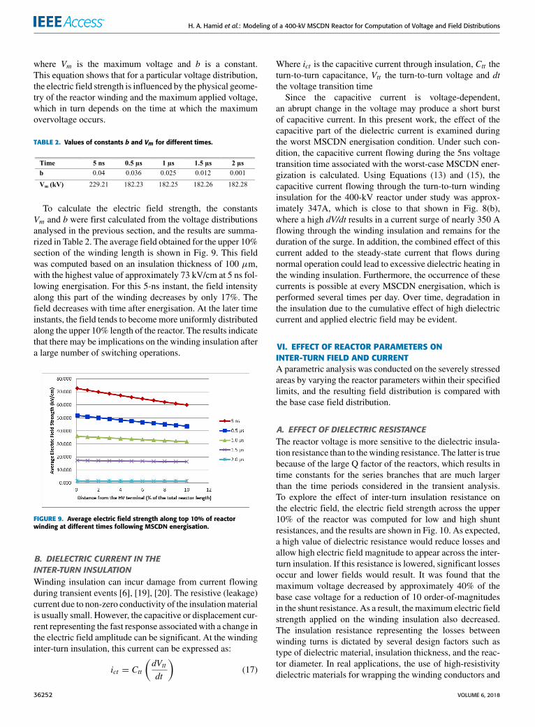
To calculate the electric field strength, the constantsVm and b were first calculated from the voltage distributionsanalysed in the previous section, and the results are summa-rized in Table 2. The average field obtained for the upper 10%section of the winding length is shown in Fig. 9. This fieldwas computed based on an insulation thickness of 100 µm,with the highest value of approximately 73 kV/cm at 5 ns fol-lowing energisation. For this 5-ns instant, the field intensityalong this part of the winding decreases by only 17%. Thefield decreases with time after energisation. At the later timeinstants, the field tends to becomemore uniformly distributedalong the upper 10% length of the reactor. The results indicatethat there may be implications on the winding insulation aftera large number of switching operations.
FIGURE 9. Average electric field strength along top 10% of reactorwinding at different times following MSCDN energisation.
B. DIELECTRIC CURRENT IN THEINTER-TURN INSULATIONWinding insulation can incur damage from current flowingduring transient events [6], [19], [20]. The resistive (leakage)current due to non-zero conductivity of the insulationmaterialis usually small. However, the capacitive or displacement cur-rent representing the fast response associated with a change inthe electric field amplitude can be significant. At the windinginter-turn insulation, this current can be expressed as:
ict = Ctt
(dVttdt
)(17)
Where ict is the capacitive current through insulation, Ctt theturn-to-turn capacitance, Vtt the turn-to-turn voltage and dtthe voltage transition time
Since the capacitive current is voltage-dependent,an abrupt change in the voltage may produce a short burstof capacitive current. In this present work, the effect of thecapacitive part of the dielectric current is examined duringthe worst MSCDN energisation condition. Under such con-dition, the capacitive current flowing during the 5ns voltagetransition time associated with the worst-case MSCDN ener-gization is calculated. Using Equations (13) and (15), thecapacitive current flowing through the turn-to-turn windinginsulation for the 400-kV reactor under study was approx-imately 347A, which is close to that shown in Fig. 8(b),where a high dV/dt results in a current surge of nearly 350 Aflowing through the winding insulation and remains for theduration of the surge. In addition, the combined effect of thiscurrent added to the steady-state current that flows duringnormal operation could lead to excessive dielectric heating inthe winding insulation. Furthermore, the occurrence of thesecurrents is possible at every MSCDN energisation, which isperformed several times per day. Over time, degradation inthe insulation due to the cumulative effect of high dielectriccurrent and applied electric field may be evident.
VI. EFFECT OF REACTOR PARAMETERS ONINTER-TURN FIELD AND CURRENTA parametric analysis was conducted on the severely stressedareas by varying the reactor parameters within their specifiedlimits, and the resulting field distribution is compared withthe base case field distribution.
A. EFFECT OF DIELECTRIC RESISTANCEThe reactor voltage is more sensitive to the dielectric insula-tion resistance than to thewinding resistance. The latter is truebecause of the large Q factor of the reactors, which results intime constants for the series branches that are much largerthan the time periods considered in the transient analysis.To explore the effect of inter-turn insulation resistance onthe electric field, the electric field strength across the upper10% of the reactor was computed for low and high shuntresistances, and the results are shown in Fig. 10. As expected,a high value of dielectric resistance would reduce losses andallow high electric field magnitude to appear across the inter-turn insulation. If this resistance is lowered, significant lossesoccur and lower fields would result. It was found that themaximum voltage decreased by approximately 40% of thebase case voltage for a reduction of 10 order-of-magnitudesin the shunt resistance. As a result, themaximum electric fieldstrength applied on the winding insulation also decreased.The insulation resistance representing the losses betweenwinding turns is dictated by several design factors such astype of dielectric material, insulation thickness, and the reac-tor diameter. In real applications, the use of high-resistivitydielectric materials for wrapping the winding conductors and
36252 VOLUME 6, 2018

H. A. Hamid et al.: Modeling of a 400-kV MSCDN Reactor for Computation of Voltage and Field Distributions
FIGURE 10. Effect of inter-turn insulation resistance on electric field.
insulation grading are important design solutions to helpincrease the insulation resistance.
B. EFFECT OF WINDING TURN INDUCTANCEFig. 11 shows the effect of winding inductance on the maxi-mum electric field strength. These results were obtained byincreasing, respectively decreasing, the inductance of eachwinding section by 50% of its base case value. As can beseen, the winding inductance has no effect on the electric fielddistribution. This is expected because the magnetic field inthe inductance requires a build-up time higher than that overwhich the transient analysis is performed. Usually, when theapplied voltage is maintained for a sufficient time, apprecia-ble currents begin to flow in the inductances, leading to nearlyuniform voltage distribution.
FIGURE 11. Effect of winding turn inductance on electric field.
C. EFFECT OF INTER-TURN CAPACITANCEThe effect of inter-turn capacitance on the electric fieldstrength was considered for lower and higher inter-turncapacitances, relative to its base case value. Fig. 12 showsthe electric field across the upper 10% of the reactor windingconsidered for three values of inter-turn capacitances: thebase value which was computed using (13) as 19.16 pF, andthe two other capacitances are one order of magnitude lowerand one order of magnitude higher than the base value.
FIGURE 12. Effect of inter-turn capacitance on electric field.
For one order of magnitude decrease in the inter-turncapacitance, the voltage across the uppermost inter-turnwinding was found to increase by approximately 200% fromits base case value. The resultant electric field strengthreached a maximum of about 220 kV/cm, which exceedsthe manufacturer-specified dielectric strength for Mylarpolyester film of 170 kV/cm [21]. Furthermore, it was foundthat low inter-turn capacitance may reduce the capacitive cur-rent that is flowing through the inter-turn winding insulation.Using Equation (17), the capacitive current obtained in thiscase was approximately 260 A, which is lower than the valueof 350 A corresponding to the base case. On the other hand,the voltage distribution over the upper 10% of the reactoris greatly improved, and decreases by approximately 60%when the capacitance increases by one order of magnitude.Interleaving is used for increasing the inter-turn capacitanceand improving the transient response of the windings, as isoften used with transformers [22].
FIGURE 13. Effect of capacitance to ground on electric field.
D. EFFECT OF CAPACITANCE-TO-GROUNDFig. 13 shows the electric field strength distribution onthe upper 10% of the reactor winding considered for lowand high capacitances-to-ground, obtained by decreasing,respectively increasing the base capacitance to groundof 2.516 pF calculated using (14) by one order of magnitude.
VOLUME 6, 2018 36253

H. A. Hamid et al.: Modeling of a 400-kV MSCDN Reactor for Computation of Voltage and Field Distributions
For high capacitance-to-ground, the maximum electric fieldstrength increases by approximately 180% from the base-case value. Furthermore, increasing capacitance-to-groundmay also increase the capacitive dielectric current flow ofthe inter-turn insulation. In this case, the capacitive currentwas approximately 380 A. For large reactor ratings, thecapacitance-to-ground tends to become smaller relative tothe inter-turn capacitance. Hence if the ground capacitanceis reduced, more current will flow through the inter-turncapacitances, leading to more uniform voltage distributionalong the winding.
In summary, a reduction of the electric field strengthis obtained by increasing the inter-turn capacitance andreducing the capacitance-to-ground of the reactor. However,such a requirement of high inter-turn capacitance and lowcapacitance-to-ground is commonly associated with the reac-tor cost and design, as well as other electrical and mechanicalfactors. For instance, changing the insulation thickness and/orpermittivity to increase the inter-turn capacitance may not bepractically feasible as it may affect safety issues of the reactordesign. A better alternative for controlling the capacitance-to-ground (Cg) is by changing the reactor height above ground.The capacitance-to-ground is also dependent on electrodesconfiguration, the radial gap and the circumferential areasbetween the windings. These parameters are usually fixedaccording to optimum electrical design considerations.
VII. POSSIBLE FAILURE MECHANISMSOF MSCDN REACTORSFrom the previous analysis, the parameters having the mostinfluence on transients and insulation failures occurring in thereactor windings are:
A. HIGH ELECTRIC FIELD STRENGTHThe model showed that during MSCDN energization,the reactor may be exposed to steep, high-magnitude over-voltages, which result in large potential differences across theinter-turn windings at the reactor HV terminal. This imposeshigh electric field on the insulation. The model computationsrevealed that a field strength of 72 kV/cmwas obtained on thewinding turns located at approximately 0.1% from the reactorHV terminal. Although this value is higher than its steady-state value, it is still below the dielectric strength of Mylarfilm specified by the manufacturer, which is 170 kV/cm.It is postulated that the electric field alone may not be thedominating factor that causes insulation failures in the reactorwinding, but a repeated switching overvoltage at this levelmay contribute to degradation of the insulation.
B. HIGH RATE OF CHANGE OF VOLTAGE (dV/dt)It was shown that energisation of the MSCDN results in anextremely high capacitive current on the inter-turn insulationof the reactor winding, which is directly proportional to thevoltage rate of rise. The computed displacement current in theinter-turn insulation of approximately 350 A is by itself notharmful to the insulation until it reaches a sufficiently highlevel, and leads to some energy losses. A synergetic effect
of dielectric stress and dielectric heating is believed to bethe influencing failure mechanism of the reactor insulationfailure. These are recurring phenomena and, combined withthe continuous steady state currents and voltages, may lead tofailure over a long period.
C. EFFECT OF SURGE ARRESTER OPERATIONIn Fig. 4, surge arresters were installed across the filter reactorand the damping resistor, respectively to provide necessaryprotection against overvoltages. Figure 14(a) shows the volt-age across the filter reactor when the MSCDN was switchedin at the instant of voltage maximum. The current through thesurge arrester connected parallel to the filter reactor is shownin Fig. 14(b).
FIGURE 14. (a) Reactor voltage and (b) Surge arrester current followingMSCDN energization
As can be seen, even though the magnitude of the arrestercurrent is small, its rate-of-rise is very high. The surge arresteroperated at voltage maximum around t = 25 ms. Near to thevoltage peak, a rapid voltage spike is observed. This spikewas not observed when the reactor was energized withoutthe surge arrester. Hence, surge arrester operation may causeadditional stress on the reactor insulation when energised atunfavourable time instants.
VIII. CONCLUSIONAmodel of a vertically-mounted single-layer air-core reactorof a 400-kVMSCDN is developed using a lumped parameterapproach. The model was implemented in ATP/EMTP andthe results showed that the transient voltage and field distri-butions along the reactor winding are highly non-uniform at
36254 VOLUME 6, 2018

H. A. Hamid et al.: Modeling of a 400-kV MSCDN Reactor for Computation of Voltage and Field Distributions
instants immediately following switching, with the highestvalues occurring in the upper 10% of the reactor winding.A parametric analysis showed the effects of reactor param-eters on the field strength stressing the reactor insulation,and possible failure mechanisms were identified. Practicalmethods for mitigating stress during MSCDN switching suchas insulation grading and improved design are described.
REFERENCES[1] R. C. Campos, D. O. Lacerda, and M. F. Alves, ‘‘Mechanically switched
capacitor with damping network (MSCDN)-engineering aspects of appli-cation, design, and protection,’’ in Proc. IEEE/PES Transmission Distrib.Conf. Expo., Latin Amer., Nov. 2010, pp. 316–322.
[2] IEEE Standard Requirements, Terminology, and Test Code for Dry-TypeAir-Core Series-Connected Reactors, IEEE Standard C57.16-1996, 2011.
[3] A. M. Mahdy, A. El-Morshedy, and H. I. Anis, ‘‘Insulation failure assess-ment under random energization overvoltages,’’ IEEE Trans. Ind. Appl.,vol. 32, no. 2, pp. 214–220, Mar. 1996.
[4] X. Wei, C. Shukang, and W. Jianér, and W. Yonghong, ‘‘Research on turn-to-turn insulation test method of dry-type air-core reactor,’’ in Proc. 6thInt. Conf. Properties Appl. Dielectr. Mater., vol. 2, 2000, pp. 1058–1061.
[5] Y. Xiuke and Y. Jian, ‘‘Calculation of wave process in an air core reactor,’’in Proc. Int. Conf. Energy Environ. Technol. (ICEET), 2009, pp. 96–98.
[6] Evaluation and Qualification of Electrical Insulation Systems, StandardBS EN 60505, 2011.
[7] M. M. A. Salama, ‘‘A calcualtion method for voltage distribution in a largeAIR core power reactor,’’ IEEE Trans. Power App. Syst., vol. PAS-100,no. 4, pp. 1752–1758, Apr. 1981.
[8] S. L. Varricchio and N. H. C. Santiago, ‘‘Transient voltage distributionin air core reactors,’’ in Proc. 8th Int. Symp. High Voltage Eng. (ISH),Yokohama, Japan, 1993, pp. 221–224.
[9] S. L. Varricchio and N. H. C. Santiago, ‘‘Electrical strength in air core reac-tors,’’ in Proc. 4th Int. Conf. Properties Appl. Dielectr. Mater., Brisbane,QLD, Australia, 1994, pp. 221–224.
[10] M. Popov, L. V.D. Sluis, R. P. P. Smeets, J. Lopez-Roldan, andV.V. Terzija,‘‘Modelling, simulation and measurement of fast transients in transformerwindings with consideration of frequency-dependent losses,’’ IET Electr.Power Appl., vol. 1, no. 1, pp. 29–35, Jan. 2007.
[11] M. Popov, R. P. P. Smeets, L. Van der Sluis, H. De Herdt, and J. Declercq,‘‘Analysis of voltage distribution in transformer windings during circuitbreaker prestrike,’’ in Proc. Int. Conf. Power Syst. Transients (IPST),Kyoto, Japan, Jun. 2009, pp. 1–6.
[12] M. M. A. Salama, R. F. Dudley, and G. Gela, ‘‘Calculation of steady-statesurface at winding ends of air-core power reactors,’’ IEEE Trans. PowerApp. Syst., vol. PAS-100, no. 7, pp. 3673–3678, Jul. 1981.
[13] A. A. Dahab, P. E. Burke, and T. H. Fawzi, ‘‘A complete model of a singlelayer air-cored reactor for impulse voltage distribution,’’ IEEE Trans.Power Delivery, vol. PWRD-3, no. 4, pp. 1745–1753, Oct. 1988.
[14] P. Holmberg, ‘‘Modelling the transient response of windings, lami-nated steel coresand electromagnetic power devices by means of lumpedcircuits,’’ Ph.D. dissertation, Dept. High Voltage Res., Uppsala Univ.,Uppsala, Sweden, 2000.
[15] M. Enohnyaket, ‘‘PEECmodelling and verification for broadband analysisof air-core reactors,’’ Ph.D. dissertation, Dept. Comput. Sci. Elect. Eng.,Lulea Univ. Technol., Lulea, Sweden, 2007.
[16] A. Greenwood, Electrical Transients in Power Systems, 2nd ed. New York,NY, USA: Wiley, 1991.
[17] F. Grover, Inductance Calculations; Working Formulas and Tables.New York, NY, USA: Van Nostrand, 1946.
[18] P. S. Maruvada and N. Hylten-Cavallius, ‘‘Capacitance calculations forsome basic high voltage electrode configurations,’’ IEEE Trans. PowerApp. Syst., vol. PAS-94, no. 5, pp. 1708–1713, Sep. 1975.
[19] C. Mayoux, ‘‘Degradation of insulating materials under electrical stress,’’IEEE Trans. Dielectr. Electr. Insul., vol. 7, no. 5, pp. 590–601, Oct. 2000.
[20] R. Bruetsch, M. Tari, K. Froehlich, T. Weiers, and R. Vogelsang, ‘‘Highvoltage insulation failure mechanisms,’’ in Proc. IEEE Int. Symp. Elect.Insul. (ISEI), Jun. 2008, pp. 162–165.
[21] Goodfellow, United Kingdom. (2018). Product Information. [Online].Available: http://www.goodfellow.com/E/Polyethylene-terephthalate.html
[22] M. J. Heathcote, The J&P Transformer Book, 12th ed. Great Britain, U.K.:Newnes, 1998.
HAZIAH ABDUL HAMID (M’13) receivedthe Bachelor and master’s degrees in electricalengineering from Universiti Teknologi Malaysiain 1999 and 2002, respectively, and the Ph.D.degree in electrical and electronic engineeringfrom Cardiff University, U.K., in 2012. She iscurrently a Senior Lecturer and the Dean with theSchool of Electrical System Engineering, Univer-siti Malaysia Perlis, Malaysia. Her main researchinterests are in high voltage transients, insulationsystem, and earthing system.
NOUREDDINE HARID (M’13) received thePh.D. degree in electrical engineering fromCardiffUniversity, U.K., in 1992. Since 1992, he has beenwith Academia as an Assistant Professor and anAssociate Professor. He joined Cardiff Universityin 2001. Since 2017, he has been an Associate Pro-fessor with the Khalifa University of Science andTechnology, Abu Dhabi. His main research inter-ests are in earthing systems, insulation systems,transients, breakdown phenomena, and condition
monitoring of high-voltage equipment. He is a member of IET and a fellowof the Higher Education Academy and served as a member of the BSIGEL/81 Standard Committee on Lightning Protection.
MANU A. HADDAD (M’13) received theBachelor degree in electrical engineering in 1985and the Ph.D. degree in high voltage engineeringin 1990. He is currently a Professor in electricalengineering with Cardiff University, with respon-sibility for research in high voltage engineering.His research interests are in overvoltage protec-tion, insulation systems, insulation coordination,and earthing of electrical energy systems. He haspublished an IET-Power Series Book on Advances
in High Voltage Engineering. He is a member of the CIGRE WorkingGroups and a member of BSI PEL1/2, IEC TC37. He serves on the scientificcommittees of several international conferences.
HUW GRIFFITHS (M’14) received the B.Sc.degree in electrical and electronic engineeringfrom the Polytechnic of Wales and the Ph.D.degree in electrical engineering from Cardiff Uni-versity, Cardiff, U.K. From 1983 to 1990, he wasan Engineer in distribution and transmission sys-tem design for SWaEB and CEGB, respectively.In 1990, he joined Cardiff University as a Lecturer,and researching with the high voltage group, hebecame a Senior Lecturer, a Reader, and a Profes-
sor. In 2015, he moved as a Professor to the Khalifa University of Scienceand Technology, Abu Dhabi. His research interests are grounding systems,transients, and high voltage insulation. Over many years, he has been amember of several British Standards, CENELEC, IEC, CIGRE, and CIREDcommittees, and working groups related to grounding systems. He is aChartered Engineer, and a member of IET.
VOLUME 6, 2018 36255