STATE OF CONNECTICUT DEPARTMENT OF TRANSPORTATION
768
STATE OF CONNECTICUT DEPARTMENT OF TRANSPORTATION ______________ Standard Specifications for Roads, Bridges, Facilities and Incidental Construction FORM 817 2016
Transcript of STATE OF CONNECTICUT DEPARTMENT OF TRANSPORTATION

STATE OF CONNECTICUT
DEPARTMENT OF TRANSPORTATION
______________
Standard Specifications for
Roads, Bridges, Facilities and
Incidental Construction
FORM 817
2016

CONNECTICUT DEPARTMENT OF TRANSPORTATIONJames P. Redeker…..Commissioner
STANDARD SPECIFICATIONS COMMITTEE
Thomas A. Harley, P.E., Chief EngineerRobert E. Obey, P.E., ChairmanJanet L. Mazeau, P.E., Secretary
Eric Tallarita, P.E., Assistant SecretaryTeresa Donahue, Assistant Secretary
MEMBERSLouis D. Bacho ................................................ Bridge DesignDean Cerasoli .....................................District 1, ConstructionLynn N. Cichowski .........................District 1A, ConstructionLisa N. Conroy ......................................... Traffic EngineeringJohn S. DeCastro ..................................................MaintenanceJohn S. Dunham ..................................District 4, ConstructionRobert Foley ........................................ Contract DevelopmentDomenic LaRosa ................................District 3, ConstructionRobert G. Lauzon .......................Division of Materials TestingAndrew Piraneo ................................Environmental PlanningGregory J. Soja ...........................................Consultant DesignMichael J. Strong ..........................................Facilities DesignMatthew R. Vail .................................................. State DesignD. Jay Young ......................................................Office of Rail
NON-VOTING MEMBERS
Peter Arborio ......... Connecticut Construction Industries AssociationLawrence Russ .................................. Office of the Attorney GeneralDonald Shubert .......Connecticut Construction Industries AssociationTimothy Snyder ............................. Federal Highway Administration

The following past members are acknowledged for their contributions: Lawrence J. D’Addio Saul Kardouni Ted Aldieri Kimberly Lesay Andrea M. Baughn Michael W. Lonergan Mark S. Bear Michelle A. Lynch Wayne W. Blair Brian Mercure Paul H. Breen Joseph A. Misbach Scott Bushee Dennis M. Murphy Lewis S. Cannon Joseph J. Obara Ravi V. Chandran Joseph P. Ouellette Paul N. Corrente Robert P. Raiola Jo Ann Devine Mark D. Rolfe Kenneth E. Fargnoli John H. Rorrio Daniel A. Gladowski Caswell K. Smith Arthur W. Gruhn Alan R. White James E. Hamilton Lamin Williams George Hird Denise A. YoungOther non-member contributors include the following personnel: Christopher G. Angelotti .....................Office of Construction Joseph D. Arsenault .....................................Highway Design Mary K. Baier .....................................Office of Construction Delois L. Barnes ................................................ State Design Jonathan T. Boardman ..............Division of Materials Testing Derek J. Brown .............................Connecticut Construction Monique G. Burns ...................................................District 1 James P. Connery ................................Office of Construction Timothy D. Fields .........................Consultant Bridge Design Leo L. Fontaine ................................... Engineering Services Daniel Furlani ..........................Division of Materials Testing Julie M. Georges ...........................Consultant Bridge Design Rudy H. Kamm ..................................................Maintenance Adam J. LeBlanc ..........................................Highway Design Thomas E. Lynch .....................Division of Materials Testing Robert J. MacNeill ............................District 3, Construction Mark F. Makuch ...................................... Traffic Engineering Michael F. McDonnell ........................Soils and Foundations Anna S. Mermelstein ............................... Traffic Engineering Brett M. Stoeffler .................................... Traffic Engineering Donald L. Ward ..................................Office of Construction

PURCHASING PRINTED COPIES OF THESTANDARD SPECIFICATIONS FOR ROADS, BRIDGES,
FACILITIES AND INCIDENTAL CONSTRUCTIONFORM 817
To purchase copies of these Standard Specifications - Form 817, please follow the instructions on the printed copy order form at:
http://www.ct.gov/dot/form817info
These Standard Specifications - Form 817, in a searchable document format, may also be accessed on the Department’s internet site: under “Doing Business With CTDOT” choose “Standards and Specifications” from the drop-down list, then click on “Form 816/Form 817.” Note: Open with Adobe Reader for best search results.
ITEM NUMBERING SYSTEM Item numbers, appearing in the Contract for roadway, bridge and incidental construction, consist of a 7-digit number which may be followed by a 2-digit decimal extension. The first 4 digits denote the Section number of the Standard Specification, Supplemental Specification, or Special Provision under which the item is to be constructed. The remaining digits are for Departmental coding purposes.

TABLE OF CONTENTS
Division I
GENERAL REQUIREMENTS AND COVENANTSSection Page1.01 DefinitionofTermsandPermissibleAbbreviations .............. 11.02 ProposalRequirementsandConditions ............................... 131.03 AwardandExecutionofContract ........................................ 161.04 ScopeofWork ...................................................................... 211.05 ControloftheWork .............................................................. 261.06 ControlofMaterials ............................................................. 421.07 LegalRelationsandResponsibilities ................................... 471.08 ProsecutionandProgress ..................................................... 561.09 MeasurementandPayment .................................................. 651.10 EnvironmentalCompliance .................................................. 751.11 Claims .................................................................................. 82
1.20-1.00 GeneralClausesforFacilitiesConstruction ......................... 871.20-1.01 DefinitionofTermsandPermissibleAbbreviationsfor
FacilitiesConstruction ....................................................... 881.20-1.02 ProposalRequirementsandConditionsforFacilities
Construction ..................................................................... 1001.20-1.03 AwardandExecutionofContractforFacillities
Construction ..................................................................... 1041.20-1.04 ScopeofWorkforFacilitiesConstruction ......................... 1101.20-1.05 ControloftheWorkforFacilitiesConstruction ................. 1161.20-1.06 ControlofMaterialsforFacilitiesConstruction ................ 1401.20-1.07 LegalRelationsandResponsiblitiesforFacilities
Construction ..................................................................... 1491.20-1.08 ProsecutionandProgressforFacilitiesConstruction ........ 1581.20-1.09 MeasurementandPaymentforFacilitiesConstruction ..... 1801.20-1.10 EnvironmentalComplianceforFacilitiesConstruction ..... 1911.20-1.11 ClaimsforFacilitiesConstruction ..................................... 1981.20-9.75 MobilizationandProjectCloseoutforFacilities
Construction ..................................................................... 203
Division II
CONSTRUCTION DETAILS
EARTHWORK
2.01 ClearingandGrubbing ....................................................... 2152.02 RoadwayExcavation,FormationofEmbankment
andDisposalofSurplusMaterial ..................................... 2162.03 StructureExcavation .......................................................... 2252.04 CofferdamandDewatering ................................................ 2282.05 TrenchExcavation .............................................................. 2312.06 DitchExcavation ................................................................ 236
i
2.07 Borrow................................................................................ 2372.08 Free-DrainingMaterial...................................................... 2392.09 Subgrade ............................................................................. 2402.10 WaterPollutionControl(SoilErosion) .............................. 2422.11 Anti-TrackingPad .............................................................. 2442.12 Subbase .............................................................................. 2452.13 GranularFill ....................................................................... 2462.14 CompactedGranularFill .................................................... 2472.16 PerviousStructureBackfill ................................................ 2482.19 SedimentationControlSystem ........................................... 2493.04 ProcessedAggregateBase.................................................. 2513.05 ProcessedAggregate .......................................................... 252
SURFACE COURSES OR PAVEMENTS4.01 ConcretePavement............................................................. 2554.06 BituminousConcrete .......................................................... 2684.15 PressureReliefJoint ........................................................... 289
STRUCTURES5.01 GeneralClauses .................................................................. 2905.03 RemovalofandAlterationstoExistingBridges ................ 2915.04 RailroadProtection ............................................................ 2945.06 RetainingWalls,EndwallsandSteps ................................. 2955.07 CatchBasins,ManholesandDropInlets ........................... 2975.08 ShearConnectors ............................................................... 3015.09 WeldedStuds ...................................................................... 3025.13 PolyvinylChloridePlasticPipe ......................................... 3025.14 PrestressedConcreteMembers .......................................... 3035.21 ElastomericBearingPads .................................................. 3115.22 ElastomericCompressionSeal ........................................... 3126.01 ConcreteforStructures ...................................................... 3146.02 ReinforcingSteel ................................................................ 3356.03 StructuralSteel ................................................................... 3406.05 MasonryFacing .................................................................. 3546.06 CementRubbleMasonry ................................................... 3576.07 DryRubbleMasonry .......................................................... 3586.09 RepointedMasonry ............................................................ 3596.11 Shotcrete ............................................................................. 3606.12 ConcreteCylinderCuringBox .......................................... 3626.51 Culverts .............................................................................. 3636.52 CulvertEnds ....................................................................... 3676.53 CleanExistingDrainageSystem ........................................ 369
INCIDENTAL CONSTRUCTION7.01 DrilledShafts ...................................................................... 3707.02 Piles ..................................................................................... 3867.03 Riprap .................................................................................. 4007.04 Gabions ............................................................................... 401
ii

7.05 SlopePaving ...................................................................... 402 7.06 Micropiles .......................................................................... 403 7.07 MembraneWaterproofing(WovenGlassFabric) ............. 416 7.08 Dampproofing .................................................................... 417 7.13 PermanentSteelSheetPiling ............................................. 418 7.14 TemporarySheetPiling ...................................................... 419 7.15 SheetPilingMaterialLeftinPlace .................................... 420 7.16 TemporaryEarthRetainingSystem ................................... 421 7.17 EarthRetainingSystemLeftinPlace ................................ 422 7.28 CrushedStoneforSlopeProtection ................................... 423 7.32 ConcreteBlockSlopeProtection ....................................... 423 7.51 UnderdrainandOutlets ...................................................... 424 7.55 Geotextile ........................................................................... 426 8.03 PavedDitchesandChannels .............................................. 428 8.11 ConcreteCurbing ............................................................... 429 8.13 StoneCurbing .................................................................... 430 8.14 ResetStoneCurbing .................................. ......................... . 431 8.15 BituminousConcreteCurbing ........................................... 431 8.16 GraniteSlopeCurbing ....................................................... 432 8.18 ProtectiveCompoundforBridges ....................................... 433 8.21 PrecastConcreteBarrierCurb ........................................... 434 8.22 TemporaryPrecastConcreteBarrierCurb ......................... 435 9.04 MetalBridgeRail ............................................................... 438 9.05 StoneWallFence ................................................................4 39 9.06 WireFence ......................................................................... 439 9.08 FarmWallFence ................................................................ 441 9.10 MetalBeamRail ................................................................ 442 9.11 MetalBeamRailAnchorages............................................. 444 9.12 RemoveandResetPosts,RailandRailAnchorages ......... 445 9.13 ChainLinkFence ............................................................... 447 9.14 MetalHandrail ................................................................... 449 9.15 TreeRootProtection .......................................................... 450 9.16 NoiseBarrierWall .............................................................. 450 9.18 Three-CableGuideRailing(I-BeamPosts)
andAnchorages .................................................................. 452 9.21 ConcreteSidewalksandRamps ......................................... 454 9.22 BituminousConcreteSidewalk,Bituminous
ConcreteDriveway............................................................. 456 9.23 BituminousConcreteforPatching ..................................... 457 9.24 ConcreteDrivewayRamps ................................................ 458 9.25 PavementforRailing.......................................................... 459 9.30 ObjectMarker .................................................................... 460 9.39 SweepingforDustControl................................................. 461 9.42 CalciumChlorideforDustControl .................................... 461 9.43 WaterforDustControl ....................................................... 462 9.44 Topsoil ................................................................................ 462 9.46 Liming ................................................................................ 463 9.47 BusPassengerShelter ........................................................ 464
iii

9.49 Furnishing,PlantingandMulchingTrees,Shrubs,VinesandGroundCoverPlants .............................467
9.50 TurfEstablishment ..............................................................471 9.51 RockExcavationforPlanting .............................................4739.52 SelectiveClearingandThinning .........................................4749.53 Sodding .............................................................................. 4759.70 Trafficperson ...................................................................... 4779.71 MaintenanceandProtectionofTraffic ............................... 4809.74 RemovalofExistingMasonry ........................................... 4819.75 MobilizationandProjectCloseout ..................................... 4829.76 BarricadeWarningLights .................................................. 4839.77 TrafficCone ........................................................................ 4849.78 TrafficDrum ....................................................................... 4859.79 ConstructionBarricades ..................................................... 4869.80 ConstructionStaking .......................................................... 4879.81 42InchTrafficCone........................................................... 4909.99 DisposalofBuildings ......................................................... 491
TRAFFIC CONTROL10.00 GeneralClausesforHighwayIllumination
andTrafficSignalProjects ................................................. 49310.01 TrenchingandBackfilling .................................................. 50310.02 LightStandardandTrafficControlFoundations ............... 50510.03 LightStandards .................................................................. 50610.04 RoadwayLuminaire ........................................................... 50710.06 UnderbridgeLuminaire ...................................................... 50810.08 ElectricalConduit............................................................... 50910.09 CastIronJunctionBox ....................................................... 51010.10 ConcreteHandhole ............................................................. 51110.11 4-InchDrainPipe ............................................................... 51210.12 SingleConductor ................................................................ 51310.14 CableInDuct ..................................................................... 51310.15 GroundingConductor......................................................... 51410.17 ServiceEntranceandCabinet ............................................ 51510.18 NavigationLight ................................................................ 51611.01 PoleAnchor ........................................................................ 51711.02 Pedestals ............................................................................. 51711.03 SpanPole ............................................................................ 51811.05 TrafficSignals .................................................................... 52011.06 PedestrianSignal ................................................................ 52111.07 PedestrianPushButton ...................................................... 52111.08 Controllers .......................................................................... 52211.11 LoopVehicleDetectorandSawcut .................................... 52411.12 MagneticVehicleDetector ................................................. 52611.13 ControlCable ..................................................................... 52711.14 MessengerandSpanWire .................................................. 52811.16 IlluminatedSigns ............................................................... 52911.17 AlternateFlashingSignalsforWarningSigns ................... 530
iv

11.1811.30
Removaland/orRelocationofTrafficSignalEquipment .. 531 HighMountedInternallyIlluminatedFlashingArrow ................................................................... 532
11.31 ChangeableMessageSign,RemoteControlledChangeableMessageSign.................................................. 532
12.00 GeneralClausesforHighwaySigning ............................... 53512.01 OverheadSignSupport ...................................................... 53512.02 OverheadSignSupportFoundation ................................... 53612.03 SideMountedSignFoundation .......................................... 53812.04 SignPanelOverlay ............................................................. 53912.05 Delineators ......................................................................... 54012.06 RemovalofExistingSigning,Removalof
ExistingOverheadSigning ................................................ 54012.07 SignFace-ExtrudedAluminum ....................................... 54112.08 SignFace-SheetAluminum.............................................. 54312.09 PaintedPavementMarkings ............................................... 54412.10 EpoxyResinPavementMarkings ...................................... 54512.11 RemovalofPavementMarkings ........................................ 54912.12 TemporaryPlasticPavementMarkingTape ...................... 54912.14 PreformedBlackLineMaskPavementMarkingTape ...... 55012.16 BlackEpoxyResinPavementMarkings,
BlackEpoxyResinSymbolsandLegends......................... 55112.20 ConstructionSigns ............................................................ 55213.00 Utilities ............................................................................... 55514.00 Vacant ................................................................................. 55515.00 Vacant ................................................................................. 55516.00 Vacant ................................................................................. 55518.00 GeneralClauses-ImpactAttenuationSystems ................. 55618.02 TypeA–ImpactAttenuationSystem ................................. 55618.06 TypeDPortableImpactAttenuationSystem ..................... 55718.07 TemporaryImpactAttenuationSystems ............................ 559
Division III
MATERIALS SECTIONM.01 GradationofAggregate ...................................................... 567M.02 GranularFill,Subbase,GranularBaseandSurfaces,
StoneBase,PerviousStructureBackfill,Free-DrainingMaterial,Crusher-RunStone .......................569
M.03 PortlandCementConcrete ................................................. 574M.04 BituminousConcreteMaterials ......................................... 583M.05 ProcessedAggregateBaseandPavement
SurfaceTreatment .............................................................. 611M.06 Metals ................................................................................. 614M.07 Paint ................................................................................... 620M.08 Drainage ............................................................................. 628M.09 SheetPilingandPiles ......................................................... 638M.10 RailingandFence ............................................................... 642
v

M.11 MasonryFacing,CementandDryRubbleMasonry,Brick,Mortar ..................................................... 650
M.12 BearingAreas,Riprap,SlopePaving&SlopeProtection,WaterproofingandDampproofing,StoneandGraniteSlopeCurbing,CalciumChlorideforDustControl,Wood ......... 653
M.13 RoadsideDevelopment ...................................................... 659M.14 PrestressedConcreteMembers .......................................... 671M.15 HighwayIllumination ........................................................ 674M.16 TrafficControlSignals ....................................................... 683M.17 ElastomericMaterials ........................................................ 709M.18 Signing ............................................................................... 715
ListofStandardPayItems ..................................................................... 727MetrictoEnglishApproximateConversionFactors ..............................734EnglishtoMetricApproximateConversionFactors ..............................735AlphabeticalSubjectIndex .....................................................................736
vi

1
1.01.01
DIVISION IGENERAL REQUIREMENTS AND COVENANTS
SECTION 1.01DEFINITION OF TERMS AND
PERMISSIBLE ABBREVIATIONS1.01.01—Definitions1.01.02—Abbreviations, Publications and Standards1.01.03—Abbreviations and Terms
1.01.01—Definitions: In these specifications, unless the context requires otherwise, words of the masculine gender include the feminine and the neuter, and, when the sense so indicates, words of the neuter gender may refer to any gender.ADDENDUM: Contract revisions developed and incorporated into the Contract after bid advertisement and before the opening of bid proposals.AIR OPERATIONS AREA: Any paved or unpaved airport area used or intended to be used for the unobstructed movement of aircraft, such as landings, takeoffs, and surface maneuverings.AWARD: The Department’s acceptance in writing of the proposal of the lowest responsible bidder for the work, subject to the execution and approval by the Department of a Contract therefor and the provision by the bidder of performance and payment bonds acceptable to the Commissioner to secure the performance thereof, and to such other conditions as may be specified by the Department or required by law.BID: The submission of a proposal for the work contemplated.BID ADVERTISEMENT: A public announcement soliciting bids for a contract for work to be performed or materials to be furnished.BIDDER: Any individual, firm, partnership, corporation, or combination thereof, submitting a proposal for the work contemplated, acting directly or through a duly authorized representative.BID MANUAL: “The State of Connecticut Department of Transportation Construction Contract Bidding and Award Manual,” copies of which are available from the Department’s Division of Contracts.CALENDAR DAY: Every day shown on the calendar, Sundays and holidays included.CATALOG CUT (PRODUCT DATA): Document(s) with information such as manufacturer’s product specifications, manufacturer’s installation instructions, standard color charts, wiring diagrams showing factory-installed wiring, printed performance curves and operational range diagrams. Product data that must be specially prepared because standard printed data is not suitable shall be considered shop drawings.CERTIFICATE OF COMPLIANCE: The formal document issued at the completion of a project by the State Building Inspector’s representative. The document is often referred to informally as a “Certificate of Occupancy,” “C.O.C.” or “C.O.”CHANNEL: A channel shall be interpreted to mean a natural or artificial watercourse having an average width at the bottom, after excavation, of 4 ft or more.COMMISSIONER: State of Connecticut Transportation Commissioner acting directly or through a duly-authorized representative.CONNECTICUT GUIDELINES FOR SOIL EROSION AND SEDIMENT CONTROL: This Department of Energy and Environmental Protection (DEEP) Bulletin

2
1.01.01
is intended to provide information to government agencies and the public on soil erosion and sediment control.http://www.ct.gov/deep/cwp/view.asp?a=2720&q=325660&deepNav_GID=1654%20 CONNECTICUT STORMWATER QUALITY MANUAL: This DEEP publication provides guidance on measures necessary to protect waters of the State from adverse impacts of post-construction stormwater runoff. http://www.ct.gov/deep/cwp/view.asp?a=2721&q=325704&depNav_GID=1654%20-%20download CONSTRUCTION ORDER, CHANGE ORDER: A written order signed by the Engineer for a contractor to perform work or provide supplies not required by the original Contract, setting forth the price therefor and the basis of payment for same.CONTRACT: The agreement covering the performance of the work and the furnishing of materials required for the construction of the Project. The Contract shall include the “Plans,” “Specifications” (i.e., the edition of the Department’s “Standard Specifications for Roads, Bridges, Facilities and Incidental Construction” which is in effect on the date of the Bid Advertisement), “Construction Orders,” and such other provisions as may be incorporated into the agreement, in addition to the contents of the bound Contract containing the schedule of prices, signature sheet, addenda, special provisions, required federal and State provisions, supplemental specifications, labor and wage schedules and other such material.CONTRACTOR: When the word is capitalized, it refers to the party of the second part to the Contract, acting directly or through its agents or employees. When this word is not capitalized, it is to be taken in its more general sense.CULVERT: A covered channel or a large pipe for carrying a watercourse below ground level, usually under a road or railway.DEPARTMENT: State of Connecticut Department of Transportation.DESIGNER: A duly-authorized representative of the Engineer, responsible for the design of the Project.DRAINAGE DITCH: An unpaved, artificially-constructed open depression having an average width of less than 4 feet at the bottom, after excavation, constructed for the purpose of carrying off surface water.ENGINEER: The Commissioner or Deputy Transportation Commissioner, acting directly or through a duly-authorized representative.EXECUTION OF CONTRACT: The date of execution of the Contract by the Department is the date on which the Department’s authorized signatory signs the Contract on behalf of the Department.EQUAL: A material, device, type of equipment, or method other than what is specified in the Contract, which is a recognized equivalent in substance and function to some required thing specified in the Contract, taking into account quality, workmanship, economy of operation, durability, and suitability for purposes intended, provided that the proposed equivalent would not require or constitute a change in the Contract work.FIXED COSTS: Any labor, material and equipment costs directly incurred for the item or items under consideration, which are necessary for the fulfillment of a Contract requirements and which remain constant regardless of the quantity of the work done.HIGHWAY: A general term denoting a public way used for vehicular travel. When referred to in the Contract, it signifies the whole right of way reserved for or secured by the Department for use in constructing or maintaining a roadway and its appurtenances.

3
1.01.01
INSPECTOR: A duly-authorized representative of the Engineer, assigned to make inspections of the work performed and materials furnished by the Contractor.LABORATORY: The official testing laboratory of the Department, unless the Department designates another laboratory to provide services in connection to the Project.LIQUIDATED DAMAGES: The amount prescribed in the Contract specifications, to be paid to the State or to be deducted from any payments due or to become due the Contractor, for a specified time unit delay in completing the whole or any specified portion of the work beyond the time allowed in the Contract.MAJOR AND MINOR ITEMS: The original Contract item of greatest cost, computed at the original Contract price and quantity, and such other original Contract items next in sequence of lower cost, computed at original Contract price and quantity, necessary to equal a total cost at the original prices and quantities of not less than 60 percent of the original aggregate Contract cost shall be considered to be a major item or major items. All other original items shall be considered to be minor items.MANAGER OF CONTRACTS: The Transportation Manager of Contracts, who is the head of the Department’s Division of Contracts, and whose office is located at the headquarters of the Department at 2800 Berlin Turnpike, Newington, CT 06111.MATERIAL: Any substance specified in the Contract for use in the construction of the Project, including appurtenances of products that are substantially shaped, cut, worked, mixed, finished, refined or otherwise fabricated, processed, or installed in order to be used for the Project work or become a part of the constructed Project.MUNICIPALITY: City, town or county.NOTICE TO PROCEED: A written notice issued by the Engineer to the Contractor stating the date on which the Contractor is authorized to commence and proceed with the Contract work.PAVEMENT STRUCTURE: The combination of sub-base, base course and surface course placed on subgrade to support and distribute the traffic load.PLANS: All drawings or reproductions of drawings supplied by the Department to the Contractor pertaining to the construction or details of the Project.
A. Standard Sheets – Standardized plans containing details approved by the Department and the FHWA, for construction of a given type on any project, included in contracts on an as-needed basis.
PRODUCT DATA (CATALOG CUT): Document(s) with information such as manufacturer’s product specifications, manufacturer’s installation instructions, standard color charts, wiring diagrams showing factory-installed wiring, printed performance curves and operational range diagrams. Product data that must be specially prepared because standard printed data is not suitable shall be considered shop drawings.PROJECT: All work included under one Department contract, notwithstanding the occasional use by the Department of multiple project numbers for the work included within one contract.PROJECT SITE (or Site): The space available to the Contractor, under the Contract, for performing construction activities. The extent of the Project site is as indicated on the plans or elsewhere in the Contract.QUALIFIED PRODUCTS LIST (QPL): A report that has been developed as a means for determining what products, suppliers, manufacturers, equipment and methodologies

4
1.01.01
may be used on construction projects. This report can be located on the CT Department of Transportation website: http://www.ct.gov/dot/cwp/view.asp?a=1387&q=259630 RECLAIMED CONCRETE AGGREGATE: Reclaimed waste consisting of crushed and graded concrete removed from pavements, structures, or buildings. Metal may be acceptable only where it is contained as reinforcement within small fragments of concrete; e.g., metal projecting from concrete fragments would be unacceptable. All such material trucked from beyond the limits of the Project must be accompanied by a materials certificate and certified test report indicating that the material is environmentally acceptable and structurally sound in accordance with Section 1.06.07, unless the source of the material is a Department Project and that source is acceptable to the Engineer.RECLAIMED MISCELLANEOUS AGGREGATE: Glass-free and clinker-free reclaimed waste that has been crushed, graded and blended, as specified in the Contract, with natural crushed stone or gravel. Metal may be acceptable only where it is contained as reinforcement within small fragments of concrete; e.g., metal projecting from concrete fragments would be unacceptable. All such material trucked from beyond the limits of the Project must be accompanied by a materials certificate and certified test report indicating that the material is environmentally acceptable and structurally sound in accordance with Section 1.06.07, unless the source of the material is a Department Project and that source is acceptable to the Engineer.RECLAIMED WASTE: Debris from the demolition of buildings, structures, and pavements; residue from incineration and recycled glass. Acceptable material shall include concrete, bituminous concrete,glass, ceramics, brick, pavement sub-base and base courses, and clinker from resource recovery plants. Metal may be acceptable only when it is contained within large fragments of concrete. Reclaimed waste trucked from beyond the limits of the Project must be accompanied by a materials certificate and certified test report indicating that the waste is environmentally acceptable and structurally sound in accordance with Section 1.06.07, unless the source of the material is a Department Project and that source is acceptable to the Engineer.RIGHT-OF-WAY: A general term denoting land, property of interest therein, usually in a strip, acquired for or devoted to transportation purposes.ROADBED: The graded portion of a highway, including portions within the top and side slopes, that has been prepared as a foundation for the pavement structure and shoulders.ROADWAY: The portion of the highway, including shoulders, which may be used for vehicular travel within the Project limits.SHOP DRAWINGS: Drawings, including proposed details, diagrams, schedules, procedures and other supporting data, prepared by a Contractor to supplement the Contract Documents, showing all information necessary for fabrication of items for which some specific design or detail appears in the Contract.SHOULDER: The portion of the roadway adjacent to the traveled way that is capable of accommodating stopped vehicles for emergency use, and of providing lateral support for base and surface courses.SPECIFICATIONS: Contractual provisions and requirements for the performance of the Contract.

5
1.01.02
A. Standard Specifications—A book of specifications published and approved by the Department for general application and repetitive use, available from the Manager of Contracts and entitled the “Standard Specifications for Roads, Bridges and Incidental Construction.”
B. Supplemental Specifications—Approved additions to and revisions of the Standard Specifications.
C. Special Provisions—Other Department specifications applicable to an individual project.
STATE: State of Connecticut.SUBCONTRACTOR: Any individual, firm, partnership or corporation to which the Contractor sublets, with the approval of the Commissioner, any part or parts of the Project.SUBSTANTIAL COMPLETION: The date at which the performance of all work on the Project has been completed except minor or incidental items, final cleanup, work required under a warranty, and repair of unacceptable work, provided the Engineer has determined:
A. The Project is safe and convenient for use by the publicB. All traffic lanes including all safety appurtenances are in their final configuration.C. Failure to complete the work (including repairs) excepted above has not and will
not result in the deterioration of other completed Project work, and provided further, that the Contract value of the work remaining to be performed, including cleanup, is less than one percent (1%) of the estimated final Contract amount
D. If applicable, a Certificate of Compliance has been issued.SUBSTITUTE: A replacement for a specified material, device, type of equipment, or method required by the Contract, which is sufficiently different in substance and function, quality, or workmanship that its use will constitute a change in the Contract work.SUBSTRUCTURE: All of that part of the bridge below the bearings of simple and continuous spans, skewbacks of arches and tops of footings of rigid frames, including backwalls, wingwalls and any protective railings mounted on the wingwalls.SUB-SUBCONTRACTOR: Any individual, firm, partnership or corporation with which a subcontractor contracts, with the approval of the Commissioner, for the performance of any part or parts of the Project.SUPERSTRUCTURE: The entire bridge except the substructure.UTILITY: Any public service company and the plant of such a company or similar facilities. Such companies include, but are not limited to, companies selling or controlling the sale, distribution or use of water, gas, electricity, communications systems, sewers or rail services. Such facilities include, but are not limited to, wires, cables, ducts, pipes, manholes, transformers, poles, towers and tracks.WORK: The provision of labor, materials or services necessary for or relating to the design and construction of the Project.WORKING DRAWINGS: Drawings, calculations, procedures and other supporting data prepared by a Contractor, documenting the Contractor’s proposed design, details, materials, construction methods and equipment for any portion of Project construction for which no specific design or detail appears in the Contract.
1.01.02—Abbreviations, Publications and Standards: Whenever one of the following abbreviations is used in the Contract, its meaning shall be interpreted as

6
1.01.02
follows:AA—(The) Aluminum Association, Inc.AABC—Associated Air Balance CouncilAAMA—American Architectural Manufacturers AssociationAAPA—American Association of Port AuthoritiesAASHTO—American Association of State Highway and Transportation Officials:
Wherever reference is made to an AASHTO Standard Method of Test or Standard Specification, it refers by letter and number to the method or specification published by AASHTO in the “Standard Specifications for Transportation Materials and Methods of Sampling and Testing.” The edition governing the Project work shall be the edition in effect on the date that the Contract was advertised for solicitation of bids.
ABMA—American Bearing Manufacturers AssociationACGIH—American Council of Government Industrial HygienistsACI—ACI (American Concrete Institute) InternationalACOE—Army Corps of EngineersADAAG—Americans with Disabilities Act (ADA) Accessibility Guidelines for
Buildings and FacilitiesADSC—The International Association of Foundation Drilling (formerly Association of Drilled Shaft ContractorsAF&PA—American Forest & Paper AssociationAGA—American Gas AssociationAGC—(The) Associated General Contractors of AmericaAHA—American Hardboard AssociationAHAM—Association of Home Appliance ManufacturersAI—Asphalt InstituteAIA—(The) American Institute of Architects AISC—American Institute of Steel ConstructionAISI—American Iron and Steel InstituteAITC—American Institute of Timber ConstructionA.L.I.—Automotive Lift InstituteALSC—American Lumber Standard Committee, IncorporatedAMCA—Air Movement and Control Association International, Inc.AMRL—AASHTO Materials Reference LaboratoryANLA—American Nursery and Landscape AssociationANSI—American National Standards InstituteAOAC—Association of Official Agricultural Chemists InternationalAOSA—Association of Official Seed AnalystsAPA—APA-The Engineered Wood AssociationAPI—American Petroleum InstituteAREMA—American Railway Engineering and Maintenance-of-Way AssociationARI—Air-Conditioning & Refrigeration InstituteARTBA—American Road and Transportation Builders AssociationASA—Acoustical Society of AmericaASC—Adhesive and Sealant CouncilASCE—American Society of Civil Engineers

7
1.01.02
ASHRAE—American Society of Heating, Refrigerating and Air-Conditioning EngineersASME—ASME International (The American Society of Mechanical Engineers
International)ASNT—American Society for Non-Destructive TestingASSE—American Society of Sanitary EngineeringASTM—American Society of Testing and Materials (ASTM International). Wherever
reference is made to an ASTM specification, test method, or practice, it refers by letter, number, or both to standards published by ASTM International in the “ASTM Standards SourceTM Database.” The edition governing the Project work shall be the edition in effect on the date that the Contract was advertised for solicitation of bids.
ATSSA—American Traffic Safety Services AssociationAWI—Architectural Woodwork InstituteAWPA—American Wood-Preservers’ AssociationAWPI—American Wood Preservers InstituteAWS—American Welding Society: Wherever reference is made to an AWS materials
specification, inspection method, or welding procedure, it refers by section number to standards of the American Welding Society published in the applicable steel, or aluminum welding code. The edition governing the Project work shall be the edition in effect on the date that the Contract was advertised for solicitation of bids.
AWWA—American Water Works AssociationBHMA—Builders Hardware Manufacturers AssociationBIA—(The) Brick Industry AssociationBOCA—BOCA International, Inc.CBM—Certified Ballast Manufacturers AssociationCCRL—Cement and Concrete Reference LaboratoryCDA—(The) Copper Development AssociationCFR—Code of Federal RegulationsCGA—Compressed Gas AssociationCGS—Connecticut General Statutes (as revised)CISCA—Ceilings and Interior Systems Construction AssociationCISPI—Cast Iron Soil Pipe InstituteCLFMI—Chain Link Fence Manufacturers InstituteConnDOT—Connecticut Department of TransportationCRI—(The) Carpet and Rug InstituteCRSI—Concrete Reinforcing Steel InstituteCSI—(The) Construction Specifications InstituteCSSB—Cedar Shake & Shingle BureauCTI—Cooling Technology InstituteDASMA—Door and Access Systems Manufacturers Association, InternationalDEEP—Connecticut Department of Energy and Environmental ProtectionDHI—Door and Hardware InstituteDOD—Department of Defense Military Specifications and StandardsEIA—Electronic Industries AllianceEPA—Environmental Protection AgencyFAA—Federal Aviation Administration FCC—Federal Communications Commission

8
1.01.02
FCICA—Floor Covering Installation Contractors AssociationFHWA—Federal Highway Administration FMG—FM GlobalFRA—Federal Railway Administration FS—Wherever reference is made to FS in the Contract, it refers by number, letter,
or both, to the latest standard or tentative standard of the Federal Specification Unit, General Services Administration, Federal Supply Service, as to materials, specifications, or methods of testing, whichever the case may be.
FTA—Federal Transit AdministrationGA—Gypsum AssociationGANA—Glass Association of North AmericaGSA—General Services AdministrationHI—Hydraulics InstituteHPVA—Hardwood Plywood & Veneer AssociationICC—International Code CouncilICC-ES—ICC Evaluation Service, Inc.ICEA—Insulated Cable Engineers Association, Inc.IEC—International Electrotechnical CommissionIEEE—Institute of Electrical and Electronics Engineers, Inc. (The)IES—Illuminating Engineers SocietyIESNA—Illuminating Engineering Society of North AmericaIGCC—Insulating Glass Certification CouncilIGMA—Insulating Glass Manufacturers AllianceIMSA—International Municipal Signal AssociationIRI—HSB Industrial Risk InsurersISO—International Organization for StandardizationITE—Institute of Traffic EngineersIUPAT—International Union of Painters and Allied TradesIWRD—Inland Wetlands Resource DivisionKCMA—Kitchen Cabinet Manufacturers AssociationLMA—Laminating Materials AssociationLPI—Lightning Protection InstituteMASH—Manual for Assessing Safety HardwareMBMA—Metal Building Manufacturers AssociationMILSPEC—Military Specification and StandardsMMA—Monorail Manufacturers AssociationMSHA—Mine Safety and Health Administration MSS—Manufacturers Standardization Society of the Valve and Fittings Industry, Inc.MUTCD—Manual on Uniform Traffic Control DevicesNAAMM—National Association of Architectural Metal ManufacturersNACE—National Association of Corrosion EngineersNADCA—National Air Duct Cleaners AssociationNAIMA—(The) North American Insulation Manufacturers AssociationNBFU—National Board of Fire UnderwritersNCHRP—National Cooperative Highway Research ProgramNCMA—National Concrete Masonry Association

9
1.01.02
NCPI—National Clay Pipe InstituteNEAUPG—NorthEast Asphalt User/Producer GroupNEBB—Natural Environmental Balancing BureauNEC—National Electrical CodeNECA—National Electrical Contractors AssociationNEMA—National Electrical Manufacturers AssociationNEPCOAT—North East Protective Coatings CommitteeNESC—National Electrical Safety CodeNETA—International Testing AssociationNETTCP—NorthEast Transportation Technician Certification ProgramNFPA—National Fire Protection AssociationNFRC—National Fenestration Rating CouncilNHLA—National Hardwood Lumber AssociationNICET—National Institute for Certification in Engineering TechnologiesNIOSH—National Institute of Occupational Safety and HealthNIST—National Institute of Standards and TechnologyNLGA—National Lumber Grades AuthorityNOAA—National Oceanic and Atmospheric AdministrationNRCA—National Roofing Contractors AssociationNRMCA—National Ready Mixed Concrete AssociationNSC—National Safety CouncilNSF—NSF InternationalNTMA—National Terrazzo and Mosaic Association, Inc.OEO—Office of Equal OpportunityOLISP—Office of Long Island Sound ProgramsOSHA—Occupational Safety and Health AdministrationPCA—Portland Cement AssociationPCI—Precast/Prestressed Concrete InstitutePDI—Plumbing & Drainage InstitutePTI—Post-Tensioning InstitutePURA—Public Utilities Regulatory AuthorityRFCI—Resilient Floor Covering InstituteRMA—Rubber Manufacturers AssociationSAE—SAE International (formerly Society of Automotive Engineers)SDI—Steel Deck Institute or Steel Door InstituteSFPA—Southern Forest Products AssociationSHRP—Strategic Highway Research ProgramSJI—Steel Joist InstituteSMACNA—Sheet Metal and Air Conditioning Contractors National AssociationSPIB—(The) Southern Pine Inspection BureauSPRI—Single Ply Roofing Institute SSPC—Where reference is made to SSPC in the Contract, it refers by number, letter,
or both, to the latest standard or tentative standard specification of The Society for Protective Coatings, formerly the Steel Structures Painting Council, as to materials specifications, methods of testing, systems, procedures, inspection or other specification pertaining to any or all phases of cleaning or painting, whichever may

10
1.01.03
apply.SWRI—Sealant, Waterproofing, & Restoration InstituteTCA—Tile Council of America, Inc.TIA—Telecommunications Industry AssociationTIA/EIA—Telecommunications Industry Association/Electronics Industries AllianceTPI—Truss Plate Institute, Inc.TRB—Transportation Research BoardUFAS—Uniform Federal Accessibility StandardsUL—Underwriters Laboratories Inc.USACOE—United States Army Corps of EngineersUSCG—United States Coast GuardUSDA—United States Department of AgricultureUSGBC—U.S. Green Building CouncilUSSWG—United States Steel Wire GaugeWCLIB—West Coast Lumber Inspection BureauWCSC—Window Covering Safety CouncilWDMA—Window & Door Manufacturers AssociationWWPA—Western Wood Products Association
1.01.03—Abbreviations and Terms: Abbreviations and terms used in the Contract are in lieu of and are to be construed in the same way as the terms or phrases following them in the list below. Those abbreviations and terms include, but are not necessarily limited to: ABS—acrylonitrile butadiene styreneAC—alternating currentACCM Pipe or ACCMP—Asphalt-Coated Corrugated Metal PipeACSR—Aluminum Conductor, Steel ReinforcedAIC—Ampere Interrupting CurrentAOEC—Area of Environmental ConcernAPA—Aquifer Protection AreaAWG—American Wire GaugeB & B—balled and burlapped bbl—barrelBCPC—Bituminous Concrete Park CurbingBit.—bituminousBit. Conc.—bituminous concreteCB—catch basinCCM Pipe or CCMP—coated corrugated metal pipeCICU—controller interface communications unitCLLCU—closed loop local coordination unitCLMU—closed loop master unitCMS—Changeable Message SignConc.—concreteCPE Pipe or CPEP—corrugated plastic or polyethylene pipeCPS—centipoise secondCWI— Certified Welding Inspectorcwt.—hundredweight or 100 pounds
11
1.01.03
DC—direct currentdist.—distillationDMT—Division of Materials TestingDTI—Direct Tension IndicatorEW—endwallest.—estimatedexc—excavationfi—jacking tensionFRC—Fiberglass Reinforced Compositef’ c—specified minimum compressive strength at a specified agef’ ci—required strength at time of transferga—gauge or gageGsa—Apparent specific gravityGsb—Bulk specific gravityHASP—Health and Safety PlanHMA—hot mix asphalt or bituminous concreteJMF—job mix formulakip—1000 poundsksf—kips per square footLED—light-emitting diodel.s.—lump summbf—1000-foot board measureMBR—metal beam railMgal—1000 gallonsMH—manholeMPT—Maintenance and Protection of TrafficN.C.—National CoarseNDT—non-destructive testingPavt.—pavementPCBC—precast concrete barrier curbPCC—Portland Cement ConcretePE—polyethylenePerf. ACCM Pipe or Perf. ACCMP—Perforated Asphalt-Coated Corrugated Metal PipePerf. CCM Pipe or Perf. CCMP—Perforated Coated Corrugated Metal PipePerf. CPE Pipe or Perf. CPEP—Perforated Corrugated Plastic or Polyethylene Pipepfmd.—preformedPROM—programmable read only memorypsf—pounds per square footpsi—pounds per square inchp/s—prestressedPVC—polyvinyl chloridePwa—Percent water absorbedRAP—reclaimed asphalt pavementRC—Reinforced ConcreteRCCE—Reinforced Concrete Culvert EndRC Pipe or RCP—Reinforced Concrete Pipe

12
1.01.03
SD—system detectorsec.—secondsol.—solublesp. gr.—specific gravitysp. visc.—specific viscositySSA—Sole Source Aquiferstd.—standardsurf.—surfaceTDC—Transportation Division ChiefTHHN—Heat resistant thermoplastic, insulated nylon jacket, 90 degrees Centigrade, 600
volt building wire THWN—Moisture and heat resistant thermoplastic, insulated nylon jacket, 75 degrees
Centigrade, 600 volt building wireTL—Test LevelTMA—Truck Mounted Impact AttenuatorTMP—Transportation Management Plantsf—tons per square footTTC—Temporary Traffic ControlU’drain or Udrain—UnderdrainUTCS—urban traffic control systemUV—ultra-violet or ultra violet lightVAC—Volts Alternating CurrentVECP—Value Engineering Change ProposalVMS—Variable Message SignVOC—Volatile Organic CompoundVT—vitrified tileW—watt WSA—Temporary Waste Stockpile Area

13
1.02.04
SECTION 1.02PROPOSAL REQUIREMENTS AND CONDITIONS
1.02.01—Contract Bidding and Award1.02.02—Vacant1.02.03—Interpretation of Estimate1.02.04—Examination of Plans, Specifications, Special Provisions and Site of Work1.02.05—Vacant1.02.06—Vacant1.02.07—Vacant1.02.08—Vacant1.02.09—Vacant1.02.10—Vacant1.02.11—Vacant1.02.12—Vacant1.02.13—Knowledge of Applicable Laws1.02.14—Vacant1.02.15—Vacant
1.02.01—Contract Bidding and Award: All bids for construction contracts must be submitted electronically. It is the responsibility of each bidder and all other interested parties to obtain all bidding related information and documents from the Department of Administrative Services (DAS) State Contracting Portal. Connecticut Department of Transportation bidding and other information and documents which are obtained from any other source must not be submitted to the Department. Reproduced, reformatted or altered forms of documents are not authorized or acceptable. For information about the bidding and award of Department construction contracts, consult the “State of Connecticut Department of Transportation Construction Contract Bidding and Award Manual,” available from the Division of Contracts and at the following link: http://www.ct.gov/dot/cwp/view.asp?a=2288&q=259258 In order to be eligible for award of a Department construction contract, a bidder must follow the requirements of this Bid Manual, and all bidding and award matters regarding Department construction contracts shall be governed by the terms of the Bid Manual, unless treated otherwise in the Contract, including these Specifications.
1.02.02—Vacant
1.02.03—Interpretation of Estimate: The quantities shown on the proposal form are approximate only and are given as a basis for the pricing upon which the award of the Contract will be made. The Department does not warrant that these quantities shall remain unchanged in the actual construction, and the Contractor may not plead misunderstanding or deception because of any variation between estimated and final quantities. The Engineer reserves the right to increase or decrease any or all of the quantities shown on the proposal form as may be necessary to properly complete the Project. The Department will pay for the actual quantity of authorized and accepted work done or material furnished under each of the items. 1.02.04—Examination of Plans, Specifications, Special Provisions and Site of Work: The bidder is required to examine carefully the site of the Contract work and

14
1.02.04
the proposal form, plans, special provisions, specifications, supplemental specifications, Contract form and other Contract documents for the work contemplated, as well as any permits or permit applications that are likely to affect the Contract work. The bidder must judge for itself and satisfy itself as to the conditions to be encountered; the character, quality and quantities of the work to be performed; the materials to be furnished; and the requirements of the above documents, particularly the requirements under each Contract item, under the general cost of the work, or under other applicable, but more general, provisions, of the Contract. The subsurface information furnished in the Contract is based on the interpretation, by the Department, of investigations made only at the specific locations indicated; and the Department gives no assurance that the conditions discovered are typical of the conditions at other Project site locations or that those conditions will have remained unchanged since the field data were obtained. The Department also gives no assurance that the presence or absence of subsurface water at the time and locations of these explorations will be representative of actual conditions at the time of construction. Such subsurface information as was obtained by the Department for its use in the design of the Project will be available for inspection by bidders through the Division of Contracts. Also, bidders may arrange through the Division of Contracts an opportunity to examine, in advance of bidding, at a location to be specified by the Department, any available samples of the materials encountered in the Department’s subsurface explorations. The Contractor shall be solely responsible for all assumptions, deductions, or conclusions it may make or derive from its examination of any Department subsurface information, document or sample. In furnishing or making available such information, the Department makes no warranty or representation as to the actual conditions that may be encountered or actual quantities or distribution of quantities of work that will be required in the course of the Project. The Department does not intend or warrant that plan sheets furnished to the State by utility companies whose facilities may be affected by the proposed construction will show all proposed utility work that will be done by utility companies or municipal authorities or both before, during, or after the life of this Contract. In addition to the work indicated on such plan sheets, the utility companies and authorities may make adjustments to or remove certain of their installations other than those indicated on the plans, or may install facilities not so indicated. Bidders must inform the Department in writing, at the earliest opportunity, of any and all omissions, errors, or discrepancies that the bidder discovers within or among the plans, specifications, and bidding documents. Information and inquiries concerning such matters, and any other information or inquiry concerning the conditions of bidding or award or the interpretation of contract documents, must be transmitted in writing to the Manager of Contracts, Connecticut Department of Transportation, P. O. Box 317546, Newington, Connecticut 06131-7546. The Department cannot ensure a response to inquiries received later than 10 days prior to the scheduled opening of the related bid. When the Department deems it warranted, responses to such inquiries that relate to changes in or interpretations of the Project documents (plans and specifications) will be issued to all bidders in the form of addenda and made a part of the Contract. Bidders are responsible for ensuring that they are aware of all addenda. Failure by the Department or postal or other courier services to deliver addenda or other information regarding a

15
1.02.15
Contract being bid does not release the bidder from any obligations under said addenda or the conditions of the bid.
1.02.05—Vacant 1.02.06—Vacant 1.02.07—Vacant 1.02.08—Vacant 1.02.09—Vacant 1.02.10—Vacant 1.02.11—Vacant 1.02.12—Vacant 1.02.13—Knowledge of Applicable Laws: Bidders shall be deemed to know and understand all federal, state and local laws, ordinances and regulations and municipal bylaws which in any manner apply to projects for which they bid; such legal requirements shall include, but not necessarily be limited to, those which apply to the conduct of the Contract work, the equipment and materials to be used on the Project, or the treatment of individuals or classes of individuals in relationship to their involvement with the Project. A Contractor’s ignorance of such requirements shall not, in any internal Department proceeding or in any claims or other legal proceeding, constitute justification for the Contractor’s failure to consider such requirements in formulating a bid proposal, or for the Contractor’s failure to ensure that such legal requirements are met with regard to any Department project in which that Contractor participates. The Contractor agrees that if it should be awarded the contract for any project supported at least in part by federal funding, the Contractor will not knowingly enter into any lower-tier transaction on that project with a person (including entities) who, by virtue of federal law or regulation, or by voluntary agreement, is currently ineligible to participate in such a project, unless after disclosure of such ineligibility, such participation is authorized by appropriate federal and State authorities. The Department expects the Contractor to obey municipal laws and regulations and cooperate with municipal officials. In some instances, however, municipal laws or regulations, or the orders of municipal officials, may conflict with necessary Project activities. In most such cases, the municipality does not have the legal power to enforce its laws and regulations upon the State or upon a State project. This is because the State is protected by its sovereign immunity. If local police or other authorities should attempt to stop the Contractor from carrying out activities that are necessary in order for the Contractor to comply with Contract requirements, the Contractor should politely inform the municipal authorities that they probably do not have jurisdiction over the State’s project, and the Contractor should immediately inform the Engineer of the attempted interference with Project activities. If the municipal authorities continue to insist upon preventing the Contractor from carrying out Project activities, the Contractor should not defy the authorities, but, to the extent possible, should await directions from the Engineer.
1.02.14—Vacant
1.02.15—Vacant

16
1.03.01
SECTION 1.03AWARD AND EXECUTION OF CONTRACT
1.03.01—Consideration of Bids1.03.02—Award and Execution of Contract1.03.03—Return of Proposal Guaranty1.03.04—Requirements of Performance Contract Bond and Payment Bond1.03.05—Vacant1.03.06—Failure to Execute Contract1.03.07—Insurance1.03.08—Notice to Proceed and Commencement of Work
1.03.01—Consideration of Bids: See Article 1.02.01.
1.03.02—Award and Execution of Contract: Except as otherwise authorized by the Commissioner, all contracts will be awarded and executed in accordance with the order of the Commissioner. The award, if made, will be made within 60 days after the opening of the proposals unless otherwise agreed upon by the Commissioner, the successful bidder, and the surety. The successful bidder, upon receipt of notice from the Department that the contract is ready for execution, shall, at the time and place designated in said notice, be present in person or be represented by an official legally authorized to sign the Contract, and shall there and then sign the necessary Project contract with the State. No proposal shall be considered binding upon the State until the proper execution of the Contract by both parties.
1.03.03—Return of Proposal Guaranty: All proposal guaranties will be returned within 3 calendar days following the award of the Contract. Ten (10) calendar days after the opening of the proposals, all guaranties, except those of the 3 lowest bidders, will be returned. Should no award be made within 60 calendar days after the opening of proposals, the Commissioner may reject all proposals and return the proposal guaranties, except that with the approval of the lowest bidder and its surety, the Commissioner may extend the time for the award and may retain the proposal and proposal guaranty of the lowest bidder for said extended time, or for any other period of time agreed upon by the Commissioner, bidder and surety.
1.03.04—Requirements of Performance Contract Bond and Payment Bond: See Article 1.02.01. In conformance with Section 49-41a of the Connecticut General Statutes, as revised, the Contractor: (1) shall, within 30 days after any given Contract payment to the Contractor by the State, pay any amounts due any subcontractor, whether for labor performed or materials furnished, when charges for such labor or materials have been included in a payment estimate paid by the State; and (2) shall include in each of its subcontracts a provision requiring each subcontractor to pay any amounts due any of its subcontractors on the Project, whether for labor performed or materials furnished, within 30 days after such subcontractor receives a payment from the Contractor which encompasses labor or materials furnished by such subcontractor for the Project. If the Contractor believes that it has a valid reason for withholding payment for

17
1.03.07
particular work or materials from a subcontractor or supplier, then the Contractor, within 30 days of receiving payment from the State for that work or materials, shall notify the subcontractor or supplier and the Department of its reasons for withholding payment.
1.03.05—Vacant
1.03.06—Failure to Execute Contract: See Article 1.02.01.
1.03.07--Insurance: Coverage shall be on a primary basis. The Contractor shall carry and maintain at all times during the term of the Contract the insurance coverages required by this article and any additional coverages(s) or higher minimum insurance coverage amount(s) required by the special provisions of the Contract. If the Project includes work on or adjacent to railroad property additional insurance may be required as specified by the railroad. Refer to the Contract special provisions for any additional insurance requirements by the railroad. 1. Worker’s Compensation Insurance: With respect to all operations the Contractor performs and all those performed for it by subcontractors, the Contractor shall carry, and require each subcontractor to carry, Workers’ Compensation insurance as required by the laws of the State of Connecticut. Employer’s Liability insurance shall be provided in amounts not less than $100,000 per accident for bodily injury by accident; $100,000 policy limit by disease and $100,000 per employee for bodily injury by disease. Each Workers’ Compensation policy shall contain the U.S. Longshoreman’s and Harbor Workers’ Act endorsement when work is to be performed over or adjacent to navigable water. 2. Commercial General Liability Insurance: With respect to the operations the Contractor performs and also those performed for it by subcontractors, the Contractor shall carry, and require each subcontractor to carry, Commercial General Liability insurance, including Contractual Liability, Products and Completed Operations, Broad Form Property Damage and Independent Contractors. Products and completed operations insurance for ongoing and completed operations shall be maintained for a period of 1 year after the acceptance of the Project by the Department in accordance with Article 1.08.14. See chart below for applicable minimum coverage amounts.
Contract Amount ($)
Minimum Single Occurrence Amount
($)
Minimum Annual Aggregate Amount
($)0-2,000,000 1,000,000 2,000,000
2,000,001-10,000,000 2,000,000 4,000,000>10,000,000 4,000,000 8,000,000
If underground work is to be undertaken, each policy shall have coverage for and exclusions removed for “Explosion, Collapse and Underground” (“XCU”). 3. Automobile Liability Insurance: The Contractor shall obtain automobile liability insurance covering the operation of all motor vehicles, including those hired or borrowed, that are used in connection with the Project for all damages arising out of: (1) bodily injury to or death of all persons and/or (2) injury to or destruction of property; in any one accident or occurrence.

18
1.03.07
This policy shall not be subject to an annual aggregate limitation. See chart above for applicable minimum coverage amounts. 4. Owner’s and Contractor’s Protective Liability Insurance for and in the Name of the State: With respect to the Contractor’s Project operations and also those of its subcontractors, the Contractor shall carry, for and on behalf of the State for each accident or occurrence resulting in damages from (1) bodily injury to or death of persons and/or (2) injury to or destruction of property. See chart below for applicable minimum coverage amounts.
Contract Amount ($)
Minimum Single Occurrence Amount
$)
Minimum Annual Aggregate Amount
($)0 - 20 Million 1,000,000 1,000,000
20 Million - 50 Million 2,000,000 2,000,000> 50 Million 4,000,000 4,000,000
5. Railroad Protective Liability Insurance: When the Contract involves work within 50 ft of the railroad right-of-way or State-owned rail property, with respect to Project operations and also those of its subcontractors, the Contractor shall carry Railroad Protective Liability Insurance providing coverage of at least $2,000,000 for each accident or occurrence resulting in damages from (a) bodily injury to or death of all persons and (b) injury to or destruction of property, and subject to that limit per accident or
occurrence, an aggregate coverage of at least $6,000,000 for all damages during the policy period, and with all entities falling within any of the following listed categories named as insured parties:
1. the owner of the railroad right-of-way,2. the owner of any railcar licensed or permitted to travel within that affected
portion of railroad right-of-way, and 3. the operator of any railcar licensed or permitted to travel within that affected
portion of the railroad right-of-way, and with the State, if not falling within any of the above-listed categories, also named as an insured party.
6. Blasting: When explosives are to be used in the Project, the Commercial General Liability insurance policy shall include XCU coverage, in the same limits as the per occurrence policy limits. 7. Protection and Indemnity Insurance for Marine Construction Operations in Navigable Waters: If a vessel of any kind will be involved in Project work, the Contractor shall obtain the following additional insurance coverage: A. Protection and Indemnity Coverage of at least $300,000 per vessel or equal to at least the value of hull and machinery, whichever is greater. B. If there is any limitation or exclusion with regard to crew and employees under the protection and indemnity form, the Contractor must obtain and keep in effect throughout the Project a workers’ compensation policy, including coverage for operations under admiralty jurisdiction, with a limit of liability of at least $300,000 per accident or a limit equal to at least the value of the hull and machinery, whichever is greater, or for any amount otherwise required by statute.

19
1.03.07
8. Builder’s Risk Insurance: For Facilities construction projects, the Contractor shall maintain comprehensive replacement cost builder’s risk (completed value) insurance providing coverage for the entire work at the Project site, including all fixtures, machinery and equipment, any heating, cooling and constituting a permanent part of the building and shall cover portions of work located away from the site, but intended for use at the site. If it is determined that all or a portion of the project is located within an area designated as a Special Flood Hazard Area, the Contractor shall maintain flood insurance (no less than $10,000,000 sublimit). The State of Connecticut shall be named as Loss Payee. Equipment breakdown coverage may be sub limited to 50% of the project cost. 9. Architects and Engineer’s Professional Liability Insurance for Structural Engineer: If required, limits will be specified in Article 1.03.07 of the Special Provisions of the Contract or in Article 1.05.02. 10. Umbrella Liability Insurance: The Contractor may satisfy the minimum limits required for Commercial General Liability and Automobile Liability Insurance using Umbrella Liability Insurance. In the event that the Contractor obtains Umbrella Liability Insurance to meet the minimum coverage requirements for Commercial General Liability or Automobile Liability Insurance coverage, the Umbrella Liability Insurance policy shall have an annual aggregate at a limit not less than twice the single occurrence and must specifically endorse the State of Connecticut as an additional insured. Specifically for Bridge Projects with a low bid equal to or higher than $80,000,000, the Umbrella Liability Insurance policy must have a minimum limit of at least $25,000,000. 11. Certificate of Insurance: Before the Contract is executed, the Contractor must provide to the Department a certificate of insurance acceptable to the Commissioner and executed by an insurance company or companies satisfactory to the State of Connecticut for the insurance coverage(s) required by this Article and the Special Provisions of the Contract. The Contractor shall maintain the required insurance coverage during the entire term of the Contract. The certificate of insurance must clearly include the name of the insured and identify the project for which it is being issued. 12. Copies of Policies: The Contractor shall provide, within 5 business days, a copy or copies of all applicable insurance policies when requested by the State. In providing said policies, the Contractor may redact provisions of the policy that are proprietary. This provision shall survive the expiration or termination of the Contract. 13. Sovereign Immunity: The Contractor may not assert the defense of sovereign immunity in the adjustment of claims or in the defense of any claim or suit brought against the Contractor or the State, unless the State, in writing, requests that the Contractor do so or consents to its doing. 14. Contractor Assumes Costs: The Contractor shall assume and pay all costs and billings for premiums, deductibles, self-insured retentions and audit charges earned and payable under the required insurance. 15. State Named as Additional Insured: The State must be named as an additional insured party for the Commercial General Liability and Automobile Liability insurance policies required by this Article and the Special Provisions to the Contract, and any Umbrella Liability Insurance, as applicable, obtained in accordance with this Article. Each policy shall waive right of recovery (waiver of subrogation) against the State of Connecticut.

20
1.03.08
16. Termination or Change of Insurance: a) The Contractor shall notify the Department of any cancelation of insurance carrier
or change to the required insurance coverage by submitting a new insurance certificate to the Department immediately following said cancelation or change in required coverage.
b) It is the responsibility of the Contractor to maintain evidence of a current insurance coverage with the Department for the duration of contract. It is the responsibility of the Contractor to file with the Department all renewals and new certificates of insurance issued due to changes in policy terms or changes in insurance carriers prior to the expiration dates on the forms already on file with the Department.
17. Duration of Coverage. The Contractor shall keep all the required insurance in continuous effect until the date that the Department designates for the termination of the Contractor’s responsibility, as defined by Article 1.08.14. 18. Compensation: There shall be no direct compensation allowed the Contractor on account of any premium or other charge necessary to obtain and keep in effect any insurance or bonds in connection with the Project, but the cost thereof shall be considered included in the general cost of the Project work.
1.03.08—Notice to Proceed and Commencement of Work: The Contractor shall commence and proceed with the Contract work on the date specified in a written Notice to Proceed issued by the Engineer to the Contractor. The date specified will be no later than 45 calendar days after the date of the execution of the Contract by the Department, except that if the expiration of said 45 calendar days occurs during the period between November 30 and April 1 of the following year, the Engineer may specify that the April 1 following said expiration shall be the date for the Contractor to proceed with the work. If the Engineer does not issue a Notice to Proceed to the Contractor within the said 45 calendar days, the Contractor shall have the option of canceling the Contract and its payment and performance bonds for the Project. Any failure by the Department to issue a Notice to Proceed, or to issue one on a timely basis, shall not, however, constitute a breach of the Contract. Neither the Contractor nor any other party may use such a failure as a basis for any claim against the Department for damages. The Contractor shall not begin physical Project construction prior to the date specified for same by the Engineer in the Notice to Proceed, except as may be otherwise authorized by the Engineer in writing.

21
1.04.02
SECTION 1.04SCOPE OF WORK
1.04.01—Intent of Contract1.04.02—Increased or Decreased Quantities of Minor Items, and Elimination of
Minor Items1.04.03—Changes in Quantities and Significant Changes in the Character of Work1.04.04—Differing Site Conditions1.04.05—Extra Work1.04.06—Removal and Disposal of Structures on the Work Site1.04.07—Rights in and Use of Materials Found on the Work Site
1.04.01—Intent of Contract: The intent of the Contract is to prescribe a complete work or improvement that the Contractor undertakes and is required to do in full compliance with the specifications, plans, special provisions, proposal, and other Contract documents. The Contractor shall perform all Project work in conformity with the lines, grades, typical cross-sections, dimensions, and other data shown on the plans and other Contract documents, as they may be modified by written orders from the Engineer subsequent to the date of the Contract. Said work includes the furnishing of all materials, implements, machinery, equipment, tools, supplies, transportation, labor, and all other things necessary for the satisfactory prosecution and completion of the Project.
1.04.02—Increased or Decreased Quantities of Minor Items, and Elimination of Minor Items: An increase or decrease in the quantity of a Contract item shall be deemed to have occurred for the purposes of these specifications when the total pay quantity of that item (i.e., the total number of units of that item for which payment is due to the Contractor as of the time when the work under that item has been completed) is either more or less than the estimated quantity of that item which was given in the bid proposal form or in the Contract as bid upon (referred to below in this section as the “estimated quantity” of the given item). This article shall apply only to minor Contract items, and not to major items in the original Contract. Any quantity increase or decrease from an estimated quantity, if that increase or decrease results from a significant change in the character of the work as defined in Subarticle 1.04.03(4)(a), shall be treated in accordance with the provisions of Article 1.04.03, and shall not be governed by or treated in accordance with the provisions of this article. Any such increase or decrease that occurs as the result of a differing site condition as defined in Article 1.04.04 shall be treated in accordance with the provisions of this article only to the extent that those provisions do not directly conflict with Article 1.04.04. If the total pay quantity of any minor item varies from the estimated quantity by 25% or less, payment for that item will be made at the original Contract unit price therefor, unless said price is eligible for adjustment under Article 1.04.03. If the total pay quantity of any minor item varies from the estimated quantity by more than 25%, the compensation payable to the Contractor for that item will be determined in accordance with the provisions of this article. If, however, the Engineer and Contractor have executed a construction order specifying the payment to be made for the item, then payment will be made in accordance with the terms of said order. As an alternative to any and all bases for payment described in this article, the Department may, in any circumstance described in this article, make any price or payment adjustment agreed upon in writing by the Department and the Contractor.

22
1.04.02
(a) Increases of More Than 25 Percent: If the total pay quantity of a minor item exceeds the estimated quantity by more than 25%, the quantity of work in excess of 125% of the estimated quantity shall be paid one of the following ways:
(i) by adjusting the Contract unit price for the quantity exceeding 125% (and only for that “excess” quantity) in the manner described in this Article;
(ii) at the option of the Engineer, on a cost-plus basis as provided in Article 1.09.04; or (iii) on any basis agreed upon in writing by the Engineer and the Contractor.
If the Engineer does not elect to pay for said excess units on a cost-plus basis or according to such a written agreement, the price or payment adjustment shall be made according to the following principles: The increase or decrease in the unit price for the excess units of the subject item shall be the difference between the original Contract unit price and the actual unit cost, said difference to be calculated in the manner described hereafter, as of the time when work under the item was completed. If the costs of work under such item include fixed costs, all such fixed costs shall be deemed to have been recovered by the Contractor as part of the payments made by the Department for the first 125% of the estimated quantity. Such fixed costs shall therefore be excluded from any computation used to adjust the price or payment for the excess units of the given item. Subject to the above provisions, the actual unit cost of the item to be adjusted shall be determined by the Engineer in the same way that it would be determined if the work were to be paid for on a cost-plus basis as provided in Article 1.09.04. If, however, the aggregate payment for the excess number of units, if they were paid for at the original, unadjusted Contract price, would be less than $25,000, the Engineer shall not adjust the Contract unit price. (b) Decreases of More Than 25%: If the total pay quantity of any minor item is less than 75% of the estimated quantity, the original Contract unit price for the item will not be adjusted unless the Contractor gives a written request for such an adjustment to the Engineer. If the Contractor so requests, the quantity of said item performed or provided shall be paid for by
(i) adjusting the Contract unit price as hereinafter provided; (ii) at the option of the Engineer, on a cost-plus basis as provided in Article 1.09.04,
except that in this kind of instance, the Contractor’s fixed cost shall be included in the calculation; or
(iii) on any basis agreed upon in writing by the Engineer and the Contractor. The unit price paid for the decreased number of units shall not, in any case, be less than the unit price in the original Contract. On the other hand, the aggregate payment for a decreased total pay quantity of a minor item may not exceed the aggregate payment which would be made for the performance of 75% of the estimated quantity at the original Contract unit price for that item. If the Engineer does not elect to pay for the decreased quantity of units on a cost-plus basis or on a basis established by written agreement, the price or payment adjustment shall be made according to the following principles: The amount of the adjustment of the original Contract unit price shall be the difference between that unit price and the actual unit cost (including fixed costs), to be calculated as of the time all work under the item has been completed. The Engineer shall determine such actual unit costs in the same way that they would be determined if payment were to be made on a cost-plus basis under Article 1.09.04.

23
1.04.03
(c) Eliminated Items: If an item is entirely eliminated from the Contract, the Department will pay the Contractor only for costs which it incurred in connection with the eliminated item prior to the date upon which the Engineer provided the Contractor with written notice of said elimination. If the Contractor had ordered Project materials (that conformed to all pertinent Contract requirements) prior to the aforesaid date of notification, and if the orders for said materials could not have been canceled within 2 business days after the date of notification, the Department shall pay the Contractor for said materials at their actual cost to the Contractor. In such a case, the materials shall become property of the State and the actual cost of any further handling necessary to deliver them to the Department shall be assumed by the State. If the materials are returnable to their vendor and if the Engineer so directs, the Contractor shall return the materials to the vendor and the State shall reimburse the Contractor
(i) for any reasonable charges made to the Contractor by the vendor for the return of the materials, and
(ii) for the actual costs to the Contractor of its handling the materials in returning them to the vendor.
Such charges or actual costs to be paid by the Department shall be computed as though the work was being paid for on a cost-plus basis under Subarticle 1.04.02(b)(ii) and Article1.09.04.
1.04.03—Changes in Quantities and Significant Changes in the Character of Work: (1) The Engineer reserves the right to make, in writing, at any time during the work,
such changes in quantities and such alterations in the work as are necessary to satisfactorily complete the project. Such changes in quantities and alterations shall not invalidate the contract nor release the surety, and the Contractor agrees to perform the work as altered.
(2) If the alterations or changes in quantities significantly change the character of the work under the contract, whether or not changed by any such different quantities or alterations, an adjustment, excluding loss of anticipated profits, will be made to the contract. The basis for the adjustment shall be agreed upon prior to the performance of work. If a basis cannot be agreed upon, then an adjustment will be made either for or against the Contractor in such amount as the Engineer may determine to be fair and equitable.
(3) If the alterations or changes in quantities do not significantly change the character of the work to be performed under the contract, the altered work will be paid for as provided elsewhere in the Contract.
(4) The term “significant change” shall be construed to apply only to the following circumstances:(a) When the character of the work as altered differs materially in kind or nature
from that involved or included in the original proposed construction or (b) When a major item of work, as defined elsewhere in the Contract, is increased
in excess of 125% or decreased below 75% of the original Contract quantity. Any allowance for an increase in quantity shall apply only to that portion in excess of 125% of original contract item quantity, or in case of a decrease below 75%, to the actual amount of work performed.

24
1.04.04
1.04.04—Differing Site Conditions: (1) During the progress of the work, if subsurface or latent physical conditions are
encountered at the site differing materially from those indicated in the Contract or if unknown physical conditions of an unusual nature, differing materially from those ordinarily encountered and generally recognized as inherent in the work provided for in the Contract, are encountered at the site, the party discovering such conditions shall promptly notify the other party in writing of the specific differing conditions before they are disturbed and before the affected work is performed.
(2) Upon written notification, the Engineer will investigate the conditions, and if he/she determines that the conditions materially differ and cause an increase or decrease in the cost or time required for the performance of any work under the Contract, an adjustment, excluding loss of anticipated profits, will be made and the Contract modified in writing accordingly. The Engineer will notify the Contractor of his/her determination whether or not an adjustment of the Contract is warranted.
(3) No Contract adjustment that results in a benefit to the Contractor will be allowed unless the Contractor has provided the required written notice.
(4) No Contract adjustment will be allowed under this clause for any effects caused on unchanged work.
1.04.05—Extra Work: Unforeseen work made necessary by the Engineer’s changes of the Contract plans or specifications, or work that is necessary for completion of the Project, but for which no price is provided in the Contract, shall be done in accordance with the requirements of the specifications and as directed by the Engineer. The Engineer will notify the Contractor of the necessity for such extra work, stipulating its character and extent, and will notify the Contractor as to whether the Engineer wants the Contractor to propose a unit price or, instead, a lump sum, for the extra work. Within 5 days of receipt of such notification, the Contractor shall advise the Engineer, in writing, of the compensation (as a unit price or lump sum, whichever has been requested by the Engineer) that the Contractor requests as compensation for the required extra work. The Contractor’s request shall be itemized and reasonably detailed, and shall include all known or anticipated direct and indirect costs of the work, including but not limited to, the costs of all safety and other equipment, small tools, labor, subcontractor quotes, consumables, field office overhead, home office overhead, insurance, bonding, and profit. The character and extent of the extra work, together with the basis of compensation, shall be communicated to the Contractor by means of a construction order which, when signed by the Engineer, shall become a part of the Contract. If a Contractor objects to any portion of a construction order submitted to it by the Engineer for signing, and if the Contractor is not willing to sign that order or some portion of that order, the Contractor must, within 15 days of its receipt of said order, return the order with a letter to the Department’s Assistant District Engineer administering the Contract, describing specifically what portions of the order the Contractor finds objectionable, the nature of its objections, and the bases for its objections. If the Contractor does not do so, it shall be deemed to have accepted the terms of the construction order. If the Engineer changes the scope of Contract work, the Contractor shall submit a proposed revised schedule and a cost revision proposal, which takes all such changes into account, if the Contractor believes that such revisions are warranted. If the schedule is to be revised, it will be revised in accordance with Article 1.08.08.

25
1.04.07
1.04.06—Removal and Disposal of Structures on the Work Site: All structures on the Project site which are not to remain on the Project site after completion of the Project shall be removed from said site and disposed of by the Contractor once it is no longer needed for the Project, and any such structure shall then become the property of the Contractor, except as otherwise required or provided by Article 1.10.07.
1.04.07—Rights in and Use of Materials Found on the Work Site: Upon written request of the Contractor and with the written approval of the Engineer, subject to limitations which may be set forth within such approval, any stone, gravel, sand, topsoil or any material from existing bridge substructures, buildings, or other structures, found within the limits of the Project may be excavated or removed and used by the Contractor on the Project, provided that said materials meet the requirements of the specification for such materials. Any materials excavated or removed shall not be taken off the Project site unless the Engineer in writing specifically authorizes such action. The following conditions shall govern these matters: 1. Excavation or removal of materials that would necessarily be excavated or removed
in making the improvement will be paid for at the applicable Contract unit prices; and, in addition, the item for which this material is used will also be paid for at its Contract unit price. The Contractor will not be charged for such materials. The Contractor shall, without compensation, place in the embankment or elsewhere, as appropriate, sufficient suitable material to fill the space that the excavated materials would have occupied, unless otherwise directed by the Engineer.
2. The excavation or removal of materials that are not required to be excavated or removed in connection with the Contract work will not be paid for; and the Contractor will be charged for such materials at a negotiated unit price. The item for which this material is used will be paid for at its Contract unit price. The Contractor shall, without compensation, backfill with accepted material the space that the excavated materials had occupied, to the satisfaction of the Engineer, unless otherwise directed by the Engineer.
Surplus material shall be removed from the Site only with the Engineer’s written permission. The Engineer may determine that such material is not surplus and order that it be incorporated into the Project.

26
1.05.01
SECTION 1.05CONTROL OF THE WORK
1.05.01—Authority of Engineer1.05.02—Plans, Working Drawings, Shop Drawings, Product Data, Submittal Preparation and Processing, and Designer’s Action1.05.03—Conformity with Plans and Specifications1.05.04—Coordination of Special Provisions, Plans, Supplemental Specifications and Standard Specifications and Other Contract
Requirements1.05.05—Cooperation by Contractor1.05.06—Cooperation with Utilities (Including Railroads)1.05.07—Coordination with Work by Other Parties1.05.08—Schedules and Reports 1.05.09—Authority of Inspectors1.05.10—Inspection1.05.11—Removal of Defective or Unauthorized Work1.05.12—Payrolls1.05.13—Examining and Copying Contractor’s Records1.05.14—Termination Clause1.05.15—Markings for Underground Facilities1.05.16—Dimensions and Measurements1.05.17—Welding
1.05.01—Authority of Engineer: All work will be subject to the review of the Engineer. He will decide all questions as to interpretation of the plans and specifications, and questions of mutual or respective rights of the Contractor and other Department contractors. The Engineer will decide on an acceptable rate of progress, on the manner of performance, and on what will be deemed acceptable fulfillment of the Contract. The Engineer will have the right to determine the points at which the Contractor may begin work and the order in which the work shall be prosecuted in the best interests of the State within the intent of the terms in the Contract. If a Project-related dispute arises between the Contractor and Department personnel assigned to the Project, and if those parties prove unable to resolve it, the Contractor may submit a detailed written description of the dispute to the Department’s Assistant District Engineer administering the Contract. It must be understood, though, that at no time may the Contractor, because of its disagreement with the Engineer, either disregard the orders of the Engineer or halt Project construction. If the Contractor cannot resolve a Project work or pricing dispute with the Engineer, the Contractor’s proper remedy is a claim under CGS Section 4-61. A Contractor that disregards the orders of the Engineer with regard to the prosecution of Project work, or who refuses to continue Project work because of a disagreement with the Engineer, may be subject to termination of its Contract, to a subsequent finding that it is nonresponsible as an apparent low bidder for a Department contract, to the assessment of liquidated damages, and to other adverse legal or administrative action by the Department.

27
1.05.02
1.05.02—Plans, Working Drawings, Shop Drawings, Product Data, Submittal Preparation and Processing, and Designers Action: 1. Plans: The plans prepared by the Department show the details necessary to give a comprehensive idea of the construction contemplated under the Contract. The plans will generally show location, character, dimensions, and details necessary to complete the Project. If the plans do not show complete details, they will show the necessary dimensions and details, which when used along with the other Contract documents, will enable the Contractor to prepare working drawings, shop drawings or product data necessary to complete the Project. 2. Working Drawings: When required by the Contract or when ordered to do so by the Engineer, the Contractor shall prepare and submit 6 printed copies and 1 electronic copy in a pdf file format of the working drawings, signed, sealed and dated by a qualified Professional Engineer licensed to practice in the State of Connecticut, for review. The drawings shall be submitted sufficiently in advance of the work detailed, to allow for their review in accordance with the requirements specified in Subarticle 1.05.02-5 (including any necessary revisions, resubmittal, and final review). There will be no direct payment for furnishing any working drawings, procedures or supporting calculations, but the cost thereof shall be considered as included in the general cost of the work. a. Working Drawings for Permanent Construction: Drawings shall be submitted on 22
in x 34 in sheets with a border and title block similar to the Department standard. Calculations, procedures and other supporting data may be submitted on 8-1/2 in x 11 in sheets. The Contractor shall supply to the Assistant District Engineer a certificate of insurance in accordance with Article 1.03.07 at the time that the working drawings for the Project are submitted. The Contractor’s designer, who prepares the working drawings, shall secure and maintain at no direct cost to the State a Professional Liability Insurance Policy for errors and omissions in the minimum amount of $2,000,000 per error or omission. The Contractor’s designer may elect to obtain a policy containing a maximum $250,000 deductible clause, but if the Contractor’s designer should obtain a policy containing such a clause, they shall be liable to the extent of at least the deductible amount. The Contractor’s designer shall obtain the appropriate and proper endorsement of its Professional Liability Policy to cover the indemnification clause in this Contract, as the same relates to negligent acts, errors or omissions in the Project work performed by them. The Contractor’s designer shall continue this liability insurance coverage for a period of (i) 3 years from the date of acceptance of the work by the Engineer, as evidenced
by a State of Connecticut, Department of Transportation Form Number CON-500, entitled “Certificate of Acceptance of Work,” issued to the Contractor; or
(ii) 3 years after the termination of the Contract, whichever is earlier, subject to the continued commercial availability of such insurance.
b. Working Drawings for Temporary Construction: The Contractor shall submit drawings, calculations, procedures and other supporting data in a format acceptable to the Assistant District Engineer.

28
1.05.02
3. Shop Drawings: When required by the Contract, or when ordered to do so by the Engineer, the Contractor shall prepare and submit 6 printed copies and 1 electronic copy in a pdf file format of the shop drawings to the Designer for review. Review timeframes and submission locations are specified in Subarticle 1.05.02-5. Drawings shall be submitted on 22 in x 34 in sheets with an appropriate border and with a title block in the lower right-hand corner of each sheet. Procedures and other supporting data may be submitted on 8½ in x 11 in sheets. There will be no direct payment for furnishing any shop drawings, but the cost thereof shall be considered as included in the general cost of the work. 4. Product Data: When required by the Contract, or when ordered to do so by the Engineer, the Contractor shall prepare and submit 6 printed copies and 1 electronic copy in a pdf file format of the product data. The product data shall be submitted to the Designer for review, sufficiently in advance of the work detailed, to allow for their review in accordance with the review periods specified in Subarticle 1.05.02-5 (including any necessary revisions, resubmittal, and final review), and acquisition of materials, without causing a delay of the Project. The Contractor shall submit the product data in a single submittal for each element of construction. The Contractor shall mark each copy of the product data submittal to show applicable choices and options. Where product data includes information on several products that are not required, copies shall be marked to indicate the applicable information. Product data shall include the following information and confirmation of conformance with the Contract to the extent applicable: manufacturer’s printed recommendations, compliance with recognized trade association standards, compliance with recognized testing agency standards, application of testing agency labels and seals, notation of coordination requirements, Contract item number, and any other information required by the individual Contract provisions. There will be no direct payment for furnishing any product data, but the cost thereof shall be considered as included in the general cost of the work. 5. Submittal Preparation and Processing – Review Timeframes: The Contractor shall allow 30 calendar days for submittal review by the Department, from the date of receipt of printed copies in the appropriate Designer or Engineer’s office. For any submittals marked with “Revise and Resubmit” or “Rejected,” the Department is allowed an additional 20 calendar days for review of any resubmissions. An extension of Contract time will not be authorized due to the Contractor’s failure to transmit submittals sufficiently in advance of the work to permit processing. The furnishing of shop drawings, working drawings or product data, or any comments or suggestions by the Designer or Engineer concerning shop drawings, working drawings or product data, shall not relieve the Contractor of any of its responsibility for claims by the State or by third parties, as per Article 1.07.10. The furnishing of the shop drawings, working drawings and product data shall not serve to relieve the Contractor of any part of its responsibility for the safety or the successful completion of the Project construction. Submissions: Unless otherwise defined in the Contract, the Contractor shall transmit the working drawings, shop drawings and product data as follows:
a. Working drawings for permanent construction, shop drawings, and product data

29
1.05.03
shall be submitted to the Designer. A copy of the transmittal or cover letter shall be forwarded to the Assistant District Engineer of the administering Construction District.
b. Working drawings for temporary construction shall be submitted to the Assistant District Engineer of the administering Construction District.
c. If not provided in the Contract, the Contractor shall request a list detailing the delivery location and contact person for each type of submittal, from the administering Construction District.
6. Designer’s Action: The Designer or Engineer will review each submittal, mark each with a uniform, self-explanatory action stamp, and return the stamped submittal promptly to the Contractor. The Contractor shall not proceed with the part of the Project covered by the submittal until the submittal is marked “No Exceptions Noted” or “Exceptions as Noted” by the Designer or Engineer. The Contractor shall retain sole responsibility for compliance with all Contract requirements. The stamp will be marked as follows to indicate the action taken:
a. If submittals are marked “No Exceptions Noted,” the Designer or Engineer has not observed any statement or feature that appears to deviate from the Contract requirements. This disposition is contingent on being able to execute any manufacturer’s written warranty in compliance with the Contract provisions. The Contractor may proceed with the work covered in the submittal.
b. If submittals are marked “Exceptions as Noted” the considerations or changes noted by the Designer or Engineer are necessary in order for the submittal to comply with Contract requirements. The Contractor shall review the required changes and inform the Designer or Engineer if they feel the changes violate a provision of the Contract or would lessen the warranty coverage.
c. If submittals are marked “Revise and Resubmit,” the Contractor shall revise the submittals to address the deficiencies or provide additional information as noted by the Designer or Engineer. The Contractor shall allow an additional review period as specified in Subarticle 1.05.02-5.
d. If submittals are marked “Rejected,” the Contractor shall prepare and submit a new submittal in accordance with the Designer’s or Engineer’s notations. The resubmissions require an additional review and determination by the Designer or Engineer. The Contractor shall allow an additional review period as specified in Subarticle 1.05.02-5.
1.05.03—Conformity with Plans and Specifications: All work performed and all materials furnished by the Contractor must be, in the opinion of the Engineer, in conformity with the lines, grades, cross-sections, dimensions and material requirements, including tolerances, shown on the plans or indicated in the Contract specifications. If the Engineer believes that the materials or the finished product in which the materials were used are not in conformity with the plans and specifications, but believes nonetheless that the finished product is acceptable, the Engineer will then determine whether or not the work will be accepted and remain in place. If the Engineer believes that the work should be accepted, the Engineer will issue a construction order confirming the determination, and may provide therein for any equitable adjustment in the basis of payment which the Engineer deems appropriate.

30
1.05.04
If, in the opinion of the Engineer, any material provided by the Contractor, any finished product in which the materials were used, or any work performed does not conform to the plans and specifications and has resulted in an unacceptable product, the Contractor shall, at its own expense, either cure or remove and replace the unaccepted work and material, as the Engineer directs.
1.05.04—Coordination of Special Provisions, Plans, Supplemental Specifications and Standard Specifications and Other Contract Requirements: All requirements indicated on the plans or in the Standard Specifications, the Supplemental Specifications, Special Provisions or other Contract provisions shall be equally binding on the Contractor, unless there is a conflict between or among any of those requirements. In the case of such a conflict, the order of governance among those requirements, in order of descending authority, shall be as follows:
1. Environmental Permits2. Environmental Permit Applications3. Special Provisions4. Plans other than Standard Sheets (enlarged details on plans, used to clarify
construction, shall take precedence over smaller details of the same area;and information contained in schedules or tables, titled as such, shall takeprecedence over other data on plans)
5. Standard Sheets6. Supplemental Specifications7. Standard Specifications and other Contract requirements
Numerical designations of dimensions shall take precedence over dimensions calculated by applying a scale to graphic representations. Neither party to the Contract may take advantage of any obvious error or omission in the Contract. Should either party to the Contract discover such an error or omission, that party shall notify the other party of same immediately in writing. The Engineer will make such corrections and interpretations of the Contract as are necessary, in his judgment, to fulfill the purposes of the Contract that are evident from examining the Contract as a whole. If the Contract includes an item that does not have a corresponding specification for either performance or payment purposes, the Contractor shall notify the Engineer of that fact in writing at least 2 weeks prior to ordering materials for or commencing work on the item. If the Department’s documents do not contain such a specification, the Engineer shall, if possible, derive an appropriate specification from applicable AASHTO Specifications or, if necessary, ASTM Specifications. If neither of those sources provides a suitable specification, the Contractor shall seek guidance from the Engineer with regard to the item, and the Engineer will formulate a reasonable specification for the item. When compliance with two or more standards is specified, and the standards may establish different or conflicting requirements for minimum quantities or quality levels, the Contractor shall refer such issues to the Engineer for a decision before proceeding with the pertinent work.
1.05.05—Cooperation by Contractor: The Contractor will be supplied by the Department with copies of the plans, and the Contractor shall have available on the Project site at all times during the prosecution of the Project, a copy of the Contract plans and specifications. The Contractor shall give the Project constant attention to facilitate

31
1.05.05
the progress thereof, shall cooperate with the Department, and shall promptly comply with all orders and directions of the Engineer. The Contractor shall at all times during Project construction have on the Project site one of its employees who is thoroughly experienced in the type of work being performed, to supervise the work and accept directions from the Engineer. The Contractor shall always notify the Engineer of the identity of said employee representative in advance of the employee’s assignment to that position. The Contractor’s representative must have full authority to promptly execute and carry out the orders and directions of the Engineer within the terms of the Contract, and to supply such materials, equipment, tools, labor and incidentals as may be required by the Contract or by the Engineer. Voluntary Partnering: The Connecticut Department of Transportation (“Department”) wants to establish a cohesive partnership with the Contractor and its principal subcontractors on the Project, so that the partnership can draw on the strengths of each organization in order to identify and pursue the partners’ mutual Project goals. Chief among those will be the effective and efficient completion of the Project, within budget, on schedule, and in accordance with applicable plans, specifications, and other Contract provisions. If the Contractor believes at any point before or during Project construction that the creation of formal partnering between itself and the Department, with the use of a third-party facilitator, would help the Contractor and the Department (“Partners”) to reach these goals, the Contractor may submit a written request to the District Engineer of the District in which the Project will be constructed for the establishment of formal partnering between the Parties. If the Contractor makes such a request, the Department will engage in that partnering. Any costs incurred by the Partners jointly in connection with Project partnering activities, to the extent that those costs are recognized as legitimate and appropriate by both Partners, will be shared equally between them. Any other costs incurred because of partnering activities will be borne by the Partner that incurred them. If the Contractor and the Department decide to pursue a formal partnering initiative, they Contractor and The Department will arrange first to meet in order to select a third-party partnering facilitator and to plan a partnering development and team-building workshop. After they agree upon the services to be performed by the facilitator and the range of compensation for the facilitator that would be acceptable to them, the Contractor will contract accordingly for the services of said facilitator. The Department will reimburse the Contractor for 50% of the payments made under that contract, so long as the activities paid for were appropriate and within the contemplation of the Partners. At the Partners’ initial partnering meeting, the Partners will also determine who should attend the first partnering workshop, what the workshop’s agenda will be, how long the workshop should last, and when and where it will be held. Unless the Partners agree otherwise, attendance at the first partnering workshop will be mandatory for the Department’s District Engineer for the Project and the Department’s other key Project personnel, the Contractor’s on-Site Project manager and other key supervisory Project personnel, and, if the Contractor agrees to it, the key supervisory personnel of the Contractor’s principal Project subcontractors. The Partners will also request that the Project design engineers and key local government personnel send Regional/District and Corporate/State-level managers to the workshop and direct them to participate in Project

32
1.05.06
partnering activities as and when requested to do so by the Partners. With the agreement of the Partners, follow-up Project partnering workshops will be held periodically until the Department closes out the Contract. If the Partners agree on a formal partnering charter for the Project, the establishment of that charter will not change the legal relationship of the Partners to the Contract; it will not alter, supplement, or eliminate any of the Partners’ rights or obligations under the Contract.
1.05.06—Cooperation with Utilities (Including Railroads): The Engineer may anticipate that a Project construction activity will require the removal, repair, replacement or relocation of a utility appurtenance. In such an instance, the Engineer, in advance of the commencement of such activity, will notify the affected utilities, either directly or through the local government, of the anticipated nature and timing of said activity. The Engineer will endeavor to have all necessary adjustments of public or private utility fixtures, pipelines, and other appurtenances within or adjacent to the limits of Project construction made as soon as practicable, when such changes are required by the State or local government. Whenever the Engineer determines that the relocation or adjustment of poles or the overhead plant of public or private utilities or railroad facilities is dependent upon the completion of certain required Contract activities, the Contractor shall complete those activities within a reasonable length of time. Temporary and permanent changes required by the State or local government in water lines, gas lines, sewer lines, wire lines, service connections, water or gas meter boxes, water or gas valve boxes, light standards, cableways, signals and all other utility (including railroad) appurtenances within the site of the proposed Project construction are to be made by others at no expense to the Contractor, except as otherwise provided for in the Special Provisions or as noted on the plans. When the Contractor is required by the Engineer to relocate utility appurtenances, such work will be paid for as extra work unless specific bid items for such work appear in the Contract. If the Contractor, for its convenience or for any other reason, desires a change in the location of a water line, gas line, sewer line, wire line, service connection, water or gas meter box, valve box, light standard, cableway, signal or any other utility (including railroad) appurtenances, the Contractor shall satisfy the Department that the proposed relocation will not interfere with the Contractor’s or other contractors’ Project operations or their fulfillment of the requirements of the plans, and that said change will not create an obstruction or hazard to traffic. If the requested change of location is acceptable to the Engineer, the Contractor shall make its own request for such relocation work to the utility companies, pipe owners or other parties likely to be affected by said work. Such relocation work shall be done at the Contractor’s sole expense. The Contractor shall schedule its operations in such a manner as to minimize interference with the operations of the utility companies or local governments in effecting the installation of new facilities, as shown on the plans, or the relocation of their existing facilities. The Contractor shall consider in its bid all permanent and temporary utility appurtenances in their present or relocated positions and any installation of new facilities required for the Project. The Department will not make any additional compensation to

33
1.05.08
the Contractor for delays, inconvenience or damage sustained by the Contractor due to (i) interference with Project construction caused by the location, condition or operation
of utility (including railroad) appurtenances or (ii) the installation, removal, or relocation of such appurtenances; and the Contractor
may not make a claim for any such compensation.
1.05.07—Coordination with Work by Other Parties: The Contractor shall make every effort to perform its work so as not to interfere with other work for the State or other parties. In the case of a dispute with another contractor working for the Department regarding their work for the State, or in the case of a conflict between their planned operations or the needs of their projects, the Contractor shall bring that dispute or conflict to the Engineer’s attention, and the Engineer will decide how it shall be resolved. The Engineer’s decision shall be binding upon all of the contractors working for the Department who are involved in the matter. The Contractor shall, as far as possible, schedule and otherwise plan and arrange its work, and place and dispose of its Project materials, so as not to interfere with the operations of other contractors working for the State. The Contractor shall, as necessary to accomplish this goal, endeavor to coordinate and schedule its work in the way which will interfere least with the work of other parties. If the Contractor’s work or activities under the Contract come into conflict with other activities or work for the State, any financial or other liability arising from such conflicts shall be the Contractor’s; and the Contractor shall protect and save harmless the State from any and all damages or claims, and the costs of defending same, which may arise because of inconvenience, delay, financial hardship, or injuries caused to the Contractor or to other contractors as a result of such conflicts, unless: (a) The Contractor notifies the Engineer of such conflicts as soon as the likelihood
of such a conflict becomes apparent; or, if such likelihood could not have been foreseen earlier, then as soon as the conflict becomes apparent.
(b) The Contractor waits for direction from the Engineer as to how the conflict should be avoided or resolved, and the Contractor does not proceed with the work involved in the conflict until the Engineer has provided the Contractor with such direction.
(c) The Contractor follows the directions given by the Engineer for avoiding, resolving, or minimizing the conflict.
The Contractor shall be responsible for the completion of its Contract work, regardless of any interference with, or delay of, that work which may be caused by the presence or activities of other contractors working for the State.
1.05.08—Schedules and Reports: When a project coordinator is not required by the Contract the following shall apply:Baseline Bar Chart Construction Schedule: Within 20 calendar days after contract award the Contractor shall develop a comprehensive bar chart as a baseline schedule for the project. The bar chart schedule shall be submitted to the Engineer for approval and shall be based on the following guidelines: 1. The bar chart schedule shall contain a list of activities that represents the major
activities of the project. At a minimum, this list should include a breakdown by individual structure or stage, including major components of each. The bar chart schedule shall contain sufficient detail to describe the progression of the work in a

34
1.05.08
comprehensive manner. As a guide, 10 to 15 bar chart activities should be provided for each $1 million of contract value.
The following list is provided as an example only and is not meant to be all-inclusive or all applicable: General Activities Applicable to all projectsProject Constraints -Winter shutdowns -Environmental permits/application time of year restrictions -Milestones -Third Party approvals -Long lead time items (procurement and fabrication of major elements) -Adjacent Projects or work by othersAwardNotice to ProceedSigning (Construction, temporary, permanent by location)MobilizationPermits as requiredField OfficeUtility RelocationsSubmittals/shop drawings/working drawings/product dataConstruction of Waste Stock pile areaClearing and GrubbingEarthwork (Borrow, earth ex, rock ex etc.)Traffic control items (including illumination and signalization)Pavement markingsRoadway Construction (Break down into components)Drainage (Break down into components)CulvertsPlantings (including turf establishment)Semi-final inspectionFinal Cleanup As required the following may supplement the activities listed above for the specific project types indicated: a. For bridges and other structures, include major components such as abutments,
wingwalls, piers, decks and retaining walls; further breakdown by footings, wall sections, parapets etc. Temporary Earth Retention SystemsCofferdam and DewateringStructure ExcavationPiles/test pilesTemporary StructuresRemoval of SuperstructureBearing PadsStructural Steel (Break down by fabrication, delivery, installation, painting etc.)Bridge Deck

35
1.05.08
b. Multiple location projects such as traffic signal, incident management, lighting, planting and guiderail projects will be broken down first by location and then by operation. Other major activities of these types of projects should include, but are not limited to:
Installation of anchorsDriving postsFoundationsTrenching and BackfillingInstallation of Span poles/mast armsInstallation of luminariesInstallation of camerasInstallation of VMSHanging headsSawcut loopsEnergizing equipment
c. Facility Projects – Facilities construction shall reflect the same breakdown of the project as the schedule of values:
Division 2 – Existing ConditionsDivision 3 – ConcreteDivision 4 – MasonryDivision 5 – MetalsDivision 6 – Wood, Plastic, and CompositesDivision 7 – Thermal and Moisture ProtectionDivision 8 – OpeningsDivision 9 – FinishesDivision 10 – SpecialtiesDivision 11 – EquipmentDivision 12 - FurnishingsDivision 13 – Special ConstructionDivision 14 – Conveying EquipmentDivision 21 – Fire SuppressionDivision 22 – PlumbingDivision 23 – Heating, Ventilating, and Air ConditioningDivision 26 – ElectricalDivision 27 – CommunicationsDivision 28 – Electronic Safety and SecurityDivision 31 – EarthworkDivision 32 – Exterior ImprovementsDivision 33 – Utilities
2. If the Engineer determines that additional detail is necessary, the Contractor shall provide it.
3. Each activity shall have a separate schedule bar. The schedule timeline shall be broken into weekly time periods with a vertical line to identify the first working day of each week.

36
1.05.08
4. The bar chart schedule shall show relationships among activities. The critical path for the Project shall be clearly defined on the schedule. The schedule shall show milestones for major elements of work, and shall be prepared on a sheet, or series of sheets of sufficient width to show data for the entire construction period.
5. If scheduling software is used to create the bar chart schedule, related reports such as a predecessor and successor report, a sort by total float, and a sort by early start shall also be submitted.
6. Project activities shall be scheduled to demonstrate that the construction completion date for the Project will occur prior to expiration of the Contract time. In addition, the schedule shall demonstrate conformance with any other dates stipulated in the Contract.
7. The Contractor is responsible to inform its subcontractor(s) and supplier(s) of the project schedule and any relevant updates.
8. There will be no direct payment for furnishing schedules, the cost thereof shall be considered as included in the general cost of the work.
9. For projects without a Mobilization item, 5% of the Contract value will be withheld until such time as the Baseline Schedule is approved.
Monthly Updates: No later than the 10th day of each month, unless directed otherwise by the Engineer, the Contractor shall deliver to the Engineer 3 copies of the schedule to show the work actually accomplished during the preceding month, the actual time spent on each activity, and the estimated time needed to complete any activity which has been started but not completed. Each time bar shall indicate, in 10% increments, the estimated percentage of that activity which remains to be completed. As the Project progresses, the Contractor shall place a contrasting mark in each bar to indicate the actual percentage of the activity that has been completed. The monthly update shall include revisions of the schedule necessitated by revisions to the Project directed by the Engineer (including, but not limited to extra work), during the month preceding the update. Similarly, any changes of the schedule required due to changes in the Contractor’s planning or progress shall also be included. The Engineer reserves the right to reject any such revisions. If the schedule revisions extend the Contract completion date, due to extra or added work or delays beyond the control of the Contractor, the Contractor shall submit a request in writing for an extension of time in accordance with Article 1.08.08. This request shall be supported by an analysis of the schedules submitted previously. Any schedule revisions shall be identified and explained in a cover letter accompanying the monthly update. The letter shall also describe in general terms the progress of the Project since the last schedule update and shall identify any items of special interest. If the Contractor fails to provide monthly schedule updates, the Engineer has the right to hold 10% of the monthly estimated payment, or $5,000, whichever is less, until such time as an update has been provided in accordance with this provision. Biweekly Schedules: Each week, the Contractor shall submit to the Engineer a 2 week look-ahead schedule. This short-term schedule may be handwritten but shall clearly indicate all work planned for the following 2 week period. Recovery Schedules: If the updated schedule indicates that the Project has fallen behind schedule, the Contractor shall either submit a time extension request in accordance with 1.08.08 or immediately institute steps acceptable to the Engineer to improve its progress

37
1.05.10
of the Project. In such a case, the Contractor shall submit a recovery plan, as may be deemed necessary by the Engineer, to demonstrate the manner in which an acceptable rate of progress will be regained.
1.05.09—Authority of Inspectors: Inspectors employed by the Department are authorized to inspect all work done and all materials furnished for Project construction. Such inspection may extend to any part of the Project work and to the preparation or manufacture of the materials to be used for same. In case of any dispute arising between the Contractor and the inspector as to materials furnished or the manner of performing work, the inspector has the authority to reject material or stop the work until the question at issue can be referred to and decided by the Engineer. The inspector is not authorized to revoke, alter, enlarge, relax, or release any requirements of the Contract, nor to approve or accept any portion of the Contract work, nor to issue instructions contrary to the Contract. The inspector shall in no case act as a foreman, or fulfill other duties for the Contractor. Any advice that the inspector may give to the Contractor shall not be construed as binding the Department in any way, nor as releasing the Contractor from its obligation to fulfill the terms of the Contract.
1.05.10—Inspection: All materials and each part or detail of the Project work shall be subject at all times to inspection by the Engineer. Such inspection may take place on the Site or at an offsite location, such as a mill, subcontractor fabrication plant or shop, or other type of location. The Engineer shall be allowed access to all parts of the work and shall be furnished with such information and assistance by the Contractor as the Engineer deems necessary to make complete, detailed and timely inspections. Information collected by the inspector may include written observations, sketches, and photographs, and other data as deemed appropriate by the inspector. The Contractor shall allow the Engineer to collect such information without restriction on the Site and shall ensure that the Engineer will have the same unrestricted ability to gather such pertinent information regarding Project work or materials at a location controlled by a subcontractor or supplier of the Contractor. The Contractor shall always notify the Engineer of its intention to perform work on the Project Site, including the nature of the particular work it intends to perform, at least 48 hours before the Contractor commences that work. If, after receiving such notice, the Engineer decides that he needs more than 48 hours to arrange for and conduct inspection related to that work, he shall so notify the Contractor, and the Contractor shall refrain from commencing the work until the Engineer has arranged for such inspection. The Contractor may not commence any portion of its work without prior related inspection by the Engineer unless the Engineer agrees otherwise. In the absence of such advance agreement by the Engineer, any work done or material used without inspection by a Department representative may be ordered exposed for examination and testing, and then corrected or restored, all at the Contractor’s expense. The Contractor shall provide the Engineer the name(s), contact information, and location(s) of any subcontractor(s) fabricating materials or components outside the Project limits for permanent incorporation into the Project. The Contractor shall provide such information sufficiently in advance of such fabrication to allow the Engineer to schedule inspections of said fabrication, and the Contractor shall ensure that such work does not commence untill it has confirmed that the Engineer has arranged for adequate

38
1.05.11
inspection at the offiste location(s). Any such work done without inspection by a Department representative may be ordered exposed for examination and testing. If the Engineer then judges that the work requires correction or restoration, the Contractor shall perform such remedial work at its own expense. If, at any time before the Department’s acceptance of the Project, the Engineer requests the Contractor to remove or uncover any portion of the Project work for inspection by the Engineer, the Contractor shall do so. After such inspection is completed, the Contractor shall restore such portions of the work to the condition required by the Contract as construed by the Engineer. If the work or material exposed and inspected under this provision proves acceptable to the Engineer, the Department shall pay the Contractor for any removal, uncovering or restoration of its previous Contract work. The Department shall pay the Contractor for such removal, uncovering, and restoration of the prior work as extra work. If the work or material exposed and inspected proves, in the opinion of the Engineer, not to conform with Contract requirements, the Contractor shall be responsible for the costs of the removal, uncovering, correction and restoration of the work and material in accordance with the Contract or as the Engineer requires. The fact that the Engineer may have conducted or failed to conduct, or conducted insufficiently or inaccurately, any inspection of Project work will not relieve the Contractor of its responsibility to perform the Project work properly, to monitor its work and the work of its subcontractors, and to institute and maintain quality control procedures appropriate for the proper execution of Project work.
1.05.11—Removal of Defective or Unauthorized Work: Work that does not conform to the requirements of the Contract shall be remedied in a manner acceptable to the Engineer or removed and replaced at the Contractor’s expense in a manner acceptable to the Engineer. No work shall be done without appropriate lines and grades having been established in the field. Work done contrary to the instructions of the Engineer, work done beyond the lines shown on the plans, or extra work done without the Engineer’s prior written direction to perform it will be considered as unauthorized and the Department will not pay for it. Work so done may be ordered removed or replaced at the Contractor’s expense. If the Contractor fails to comply with any order of the Engineer made under the provisions of this Article, the Engineer has the authority to cause unacceptable or unauthorized work to be remedied or removed and replaced by a party or parties other than the Contractor, and to deduct the costs of such activities from any monies due or to become due to the Contractor from the Department or any other agency of the State.
1.05.12—Payrolls: For each week of the Project from the first week during which an employee of the Contractor does Project work to which prevailing wage requirements apply, until the last week on which such an employee does such work, the Contractor shall furnish to the Engineer certified copies of payrolls showing (a) the names of the employees who worked on the Project and whose work is subject
to prevailing wage requirements,(b) the specific days and hours and numbers of hours that each such employee worked
on the Project, and(c) the amount of money paid to each such employee for Project work.

39
1.05.14
Each such payroll shall include the statement(s) of compliance with prevailing wage laws required by the State of Connecticut and, if applicable, by the Federal government. Said payrolls must contain all information required by Connecticut General Statutes Section 31-53 (as it may be revised). For contracts subject to Federal prevailing wage requirements, each payroll shall also contain the information required by the Davis Bacon and Related Acts (DBR). All of the payroll requirements in this Article shall also apply to the work of any subcontractor or other party that performs work on the Project site, and the Contractor shall be responsible for ensuring that each such party meets said requirements. Every Contractor or subcontractor performing Project work is required to post the relevant prevailing wage rates as determined by the State Labor Commissioner and, on federal aid projects, those determined by the United States Secretary of Labor. The wage rate determinations shall be posted in prominent and easily accessible places at the work site.
1.05.13—Examining and Copying Contractor’s Records: The Contractor shall permit the Department and its duly-authorized representatives to examine and copy all documents and other records of the Contractor that are relevant to charges for extra work, alleged breaches of Contract, or any formal or informal claim for additional compensation or for damages in connection with the Project. With the exception noted below, the Contractor shall also permit the Department to examine and copy such of its documents and other records pertaining to the Project as the Department may deem necessary in order to determine whether or not the Contractor has complied with all laws, regulations and other governmental mandates, e.g., those relating to labor compliance, affirmative action programs, and equal employment opportunity. Documents and other records relating to the Project, if they were created prior to the opening of bids for the Contract, and if they are sought by the Department only for the purpose of confirming such compliance with legal requirements, shall, however, not be subject to examination by the Department pursuant to this Article without the consent of the Contractor. The Contractor further agrees that it shall keep all documents and other records relating to the Project at least until the expiration of 3 years after the date of acceptance of the Project by the Department, as designated in a “Certificate of Acceptance of Work and Acceptance of Project” (CON-13), issued by the Department. If any claims are brought by the Department or the Contractor prior to that expiration, however, the Contractor shall keep all such records until the Department has given the Contractor and full and final release from all pending and potential claims regarding the Project. If the Contractor does not so keep any such records, it may not assert any formal or informal claim for compensation or damages that could have been substantiated or disproven with such records. The Contractor shall ensure that the requirements of this provision are made applicable to its subcontractors and suppliers, for the State’s benefit, by including the operative language of this Article in its Project subcontracts and purchase agreements.
1.05.14—Termination for Convenience Clause: The State may terminate the Contract whenever the Engineer determines that such termination is in the best interests of the State. Any such termination shall be effected by delivery to the Contractor of a written

40
1.05.15
Notice of Termination specifying the extent to which performance of work under the Contract is terminated and the date upon which said termination shall be effective. In the case of such a termination, the Department will pay the Contractor at the Contract unit prices for the actual number of units or items of Contract work completed prior to the effective date of termination, or as may be agreed by the parties for such items of work partially completed. No claim for loss of overhead or anticipated profits shall be allowed. When the volume of work completed is too small to compensate the Contractor under Contract unit prices for its related expenses, the Department may consider reimbursing the Contractor for such expenses. Materials obtained by the Contractor for the Project, if they have been inspected, tested as required, and accepted by the Engineer, but have not been incorporated into the Project construction, shall, if the Engineer and the Contractor so agree, be purchased by the Department from the Contractor at their actual cost as shown by receipted bills. To this cost shall be added all actual costs for delivery at such points of delivery as may be designated by the Engineer, as shown by actual cost records. If the Engineer does not agree to purchase such materials, the Department shall reimburse the Contractor for any reasonable restocking fees and handling costs incurred by the Contractor in returning said materials to the vendor. Termination of the Contract shall not relieve the Contractor of its responsibilities for the completed Project, nor shall it relieve the Contractor’s surety of its obligation concerning any claims arising out of the work performed, until the requirements of Articles 1.08.13 and 1.08.14 have been met.
1.05.15—Markings for Underground Facilities: In conformance with Section 16-345 through 16-359 of the Regulations of the PURA, the Contractor is responsible for notifying “Call Before You Dig” prior to commencing any excavation, including milling, reclamation or trenching; and the Contractor shall install a warning tape located a minimum of 12 in above all conduits, wires, cables, utility pipes, drainage pipes, underdrains, or other facility, unless the excavation’s depth, other underground facilities, or other engineering considerations make this minimum separation unfeasible. The warning tape shall be of durable impervious material, designed to withstand extended underground exposure without material deterioration or fading of color. The tape shall be of the color assigned to the type of facility for surface markings and shall be durably imprinted with an appropriate warning message. The tape shall also comply with the specific requirements of the utility that owns the facility. All tapes, unless otherwise directed by the specific utility, shall be detectable to a depth of at least 3 ft with a commercial radio-type metal locator. Assigned colors are:
Green - Storm and sanitary sewers and drainage systems, including force mains and other non-hazardous materials
Blue - WaterOrange - Communication lines or cables, including, but not limited to, those
used in, or in connection with, telephone, telegraph, fire signals, cable television, civil defense, data systems, electronic controls and other instrumentation
Red - Electrical power lines, electrical power conduits and other electrical power facilities, traffic signals and appurtenances and illumination

41
1.05.17
facilitiesYellow - Gas, oil petroleum products, steam, compressed air, compressed gases
and all other hazardous material except waterBrown - OtherPurple - Radioactive materials
Payment for warning tapes shall be included in the bid price for the pay item of the specific facility for which the tape is used.
1.05.16—Dimensions and Measurements: The Contractor or one of its subcontractors shall verify each dimension that is needed in order to ensure that its work complies with the Contract, and must do so before ordering any material or doing any work for which such dimension is needed. Such dimensions include, but are not limited to, dimensions given on the plans, as well as dimensions of structures in place prior to Project construction or installed in the course of construction. The Contractor or any subcontractor that finds a discrepancy or error in dimensions must report it promptly to the Engineer and may proceed with affected work only after receiving clarification and direction from the Engineer regarding the matter. Any costs for delays, changes, cutting or repairs that are incurred due to the Contractor’s failure to observe the above requirements shall be borne by the Contractor.
1.05.17—Welding: The Contractor shall ensure that all welding of materials permanently incorporated into the work, and welding of materials used temporarily during construction of the work is performed in accordance with the following codes: (a) AWS Structural Welding Code – Steel – ANSI/AWS D1.1: Miscellaneous
steel items that are statically loaded including but not limited to columns, and floor beams in buildings, railings, sign supports, cofferdams, tubular items, and modifications to existing statically loaded structures.
(b) AWS Structural Welding Code – Aluminum – AWS D1.2/D1.2M: Any aluminum structure or member including but not limited to brackets, light standards, and poles.
(c) AWS Structural Welding Code – Sheet Steel – AWS D1.3/D1.3M: Sheet steel and cold-formed members 0.18 in or less in thickness used as, but not limited, to decking and stay-in-place forms.
(d) AWS Structural Welding Code – Reinforcing Steel – AWS D1.4/D1.4M: Steel material used in the reinforcement of cast-in-place or pre-cast Portland cement concrete elements including but not limited to bridge decks, catch basin components, walls, beams, deck units, and girders.
(e) AASHTO/AWS – Bridge Welding Code, AASHTO/AWS D1.5/D1.5M: Steel highway bridges and other dynamically loaded steel structures. Also includes sign supports, and any other fracture critical structure.
The edition governing the work shall be in effect on the date the Contract was advertised for solicitation of bids. The Contractor is responsible to provide a Certified Welding Inspector in accordance with the above noted codes. The cost for this service is included in the general cost of the work. All welders shall be certified by the Engineer in accordance with Section 6.03.

42
1.06.01
SECTION 1.06CONTROL OF MATERIALS
1.06.01—Source of Supply and Quality1.06.02—Samples and Test1.06.03—Storage1.06.04—Defective Materials1.06.05—Shipping Material1.06.06—Vacant1.06.07—Certified Test Reports and Materials Certificates1.06.08—Warranties, Guarantees and Instruction Sheets
1.06.01—Source of Supply and Quality: The Contractor must obtain the Engineer’s approval of the source of supply for each of the materials specified in the Contract before beginning delivery of such materials to the Project site. If, at any time, the Department discovers that a source of supply that had been approved does not furnish uniform materials, or if the material from any source proves unacceptable to the Engineer, the Engineer will so notify the Contractor. Thereafter, the Contractor shall furnish only approved materials from other approved sources for the Project, and shall use such approved materials to replace any previously-furnished materials that have been rejected by the Engineer. Only materials conforming to the requirements of these specifications and approved by the Engineer shall be used for the Project. No material that, after approval, has in any way become unfit for use shall be used for the Project. All permanently incorporated steel and iron used in the construction of the Project must have been produced and fabricated in the United States. It is the express intent of this specification to require that all manufacturing processes for all steel and iron materials and products to be used for the Project, including the coating of steel and iron, occur within the United States, with the following exceptions: The Contractor may request, in accordance with Section 635.410(b)(4) of Title 23 CFR, approval to include a minimal amount of foreign steel in the Project construction. This amount is defined as 1/10 of 1% of the total Contract price or $2,500.00, whichever is greater. The cost of the foreign steel or iron is defined as its Contract value when delivered to the Project site. Additionally, the FHWA has granted a nationwide waiver of the requirements of 23 CFR 635.410, Buy America requirements, for the production of pig iron and processed, pelletized, and reduced iron ore. Items not specifically included in the waiver remain subject to the Buy America requirements. The Contractor may request the Engineer to seek from the FHWA a further waiver of said requirements, but it shall be at the sole discretion of the Engineer whether or not to seek such a waiver. When the Contractor proposes to use materials from a source not currently approved by the Engineer, the Contractor shall submit as a prerequisite to consideration for source approval such evidence as the Engineer may request, showing that the materials from the proposed source meet the Contract requirements and will be available to the Contractor in sufficient quantity to assure continuous and satisfactory progress of the Project. Should it become necessary after award of the Contract for the Contractor to obtain material from sources other than those indicated in the statement on materials sources that is furnished by the Department prior to award, the Contractor shall furnish a supplementary statement and required samples of said proposed materials to the Engineer

43
1.06.02
not less than 10 calendar days prior to placing an order for any such material. For any material that requires more than 1 month for delivery, the Contractor shall provide the Engineer with documentary proof that said material has been ordered in sufficient time to complete the Project as planned. Failure to produce such documentary proof will result in a denial of any claim for a time extension based on late delivery of such material. When a particular manufacturer’s product is specified in the Contract, it shall be understood that this represents the standard required, but that a comparable product of another manufacturer may be considered as an equal and may be approved, unless the plans or special provisions indicate that no equal shall be allowed. Should a Contractor desire to use a product that he considers equal or superior to the one material specified, the Contractor shall submit to the Engineer a complete description of the proposed product, together with 7 copies of shop drawings, cuts and other descriptive literature, so as to inform the Department completely of the nature of such product before the Engineer decides whether or not to approve its use. Such approval shall not change any Contract requirement for a related Certified Test Report and Materials Certificate.
1.06.02—Samples and Test: The Contractor must obtain the Engineer’s approval of any sources of materials to be incorporated into the Project before beginning to use them for the Project. Approval of material sources may be by (1) certification accepted by the Engineer, (2) written permission of the Engineer, or (3) prior approval after documented test or inspection by the Department. Any Project work in which materials from unapproved sources are used may be considered unauthorized by the Engineer, and therefore, not to be paid for. Materials tests or inspection from sources or material delivered to a project site, when required, will be made by and at the expense of the Department, unless otherwise noted in the Contract. Certification may be used as the basis for approval of such materials, as the Contract documents specify or as the Engineer may require. With regard to such materials, the Contractor shall furnish the Engineer a Certified Test Report and Materials Certificate, conforming to Article 1.06.07, as may be required in the “Minimum Schedule for Acceptance Testing” for each type of material. The Contractor shall bear any costs involved in furnishing the Test Report and Certificate. If the Contractor has purchased materials for use on a previous Department project, and if they comply with the requirements of this Contract, then those materials, with the approval of the Engineer, may be used for the Project, provided that the Contractor, acting as the materials supplier, submits a related Materials Certificate conforming to Article 1.06.07. This Materials Certificate shall further identify the project for which the material was originally purchased and shall be accompanied by a copy of the original Certificate. Material samples required by the Department will be as indicated in the latest edition of the “Minimum Schedule for Acceptance Testing,” http://www.ct.gov/dot/cwp/view.asp?a=1410&Q=538842&PM=1 and tests will be performed in accordance with the latest revision of the standard method of AASHTO or ASTM, or in accordance with other standards accepted by the Department which are in effect at the time of bidding, unless otherwise specified on the plans or in the special provisions.

44
1.06.03
Any items not covered in the “Minimum Schedule for Acceptance Testing,” special provisions, or plans shall be sampled and tested or certified, as directed by the Engineer. The Contractor shall submit to the Engineer representative preliminary samples of any materials proposed for Project use, without charge by the Contractor or the producer of the materials. Samples submitted shall be taken by a representative of the Department or a commercial laboratory approved by the Engineer. All such materials shall be subject to inspection, testing or re-testing at the Engineer’s direction at any time during their manufacturing, fabrication or use. The Contractor shall furnish all required samples without charge, and provide secure facilities for their storage. The Contractor shall provide means for, and shall assist in the verification of, all scales, measures and other devices that it operates or uses in connection with the Project. Materials will be rejected by the Engineer whenever, in his judgment, they fail to meet Contract requirements. The Engineer may accept material or combination of materials and thereby waive noncomplying test results, provided that the following conditions are met: 1. The Engineer finds results of prior and subsequent series of tests of the material or
materials from the same source or sources to be satisfactory. 2. The incidence and degree of nonconformance with the Contract requirements are, in
the Engineer’s judgment, within reasonable limits. 3. The Contractor, in the Engineer’s judgment, had diligently exercised material
controls consistent with good practices. 4. No adverse effect on the value or serviceability of the completed work could result
from said degree of nonconformance. The Engineer may, in his discretion, waive testing of minor quantities of a particular material if said material was obtained from sources that have furnished supplies of the material that have consistently met Department testing standards.
1.06.03—Storage: The Contractor shall store all materials for the Project in a way that ensures that their quality and fitness for the Project will be preserved, and that the Engineer will have easy and prompt access to them for inspection purposes. Materials shall be kept on wooden platforms or on other hard, clean surfaces and not on the ground. When so directed by the Engineer, the Contractor shall store materials in a weatherproof building. The Contractor shall not store materials in any way that would lead to a violation of Section 1.10 of these specifications. Stored materials, even if they have been approved by the Engineer prior to their storage, must be inspected by the Engineer and meet all pertinent Contract requirements immediately prior to use of those materials for the Project.
1.06.04—Defective Materials: Unless otherwise permitted by the Engineer, all materials not conforming to Contract requirements shall be considered defective, shall be rejected, and shall be removed immediately from the Project site. If deemed necessary by the Engineer, the Engineer may require the retesting of materials previously tested, approved and incorporated into the Project. If, after such retesting, the materials are found not to conform to the Contract, the Engineer may, however, allow the Contractor to leave the materials in place, provided that an equitable reduction of the

45
1.06.07
payment for the materials shall be made. No rejected material, the defects of which have been subsequently corrected, shall be used until approval for such use has been given by the Engineer. Should the Contractor fail to comply with any order of the Engineer made under the provisions of this article, the Engineer shall have authority to remove and replace defective material, and to deduct the cost of such removal and replacement from any money due or to become due to the Contractor. When a material is fabricated or treated with another material, or when any combination of materials is assembled to form a product, any or all of which are covered by the Contract specifications, the failure of any components of the product to comply with the specifications may be sufficient cause for the rejection of the whole combination or product. Materials that have been shipped from approved deposits or sources of supply, but which are found to be defective upon their delivery to the Department, to the Project site, or to any testing or storage site approved by the Engineer, shall not be used for the Project.
1.06.05—Shipping Material: Any conveyance used for transporting materials must be clean when used, be in proper working condition, have a strong and substantial body that will prevent the loss of materials during transportation, and be approved by the Engineer.
1.06.06—Vacant
1.06.07—Certified Test Reports and Materials Certificates: The Contractor shall furnish the Engineer with any Certified Test Report and Materials Certificate required by the Contract or the “Minimum Schedule for Acceptance Testing.” The Contractor shall forward the Certified Test Report and Materials Certificate to the Engineer, and, in addition, shall deliver a copy of same to the Department’s inspector at the Site. Materials for which such documentation is required may be conditionally incorporated into the Project prior to the Engineer’s acceptance of a Certified Test Report and a Materials Certificate; however, payment for such incorporated material will not be made prior to receipt of a Certified Test Report and Materials Certificate indicating that the material(s) meets the Contract requirements. A Certified Test Report is a document containing a list of the dimensional, chemical, metallurgical, electrical and physical results obtained from a physical test of the materials involved, and shall certify that the materials meet the requirements of the Contract. Such Report shall also include the following information:
(1) Item number and description of materials(2) Date of manufacture(3) Date of testing(4) Name of organization to which the material has been consigned(5) Quantity of material represented, such as batch, lot, group, etc.(6) Means of identifying the consignment, such as label, marking, lot number, etc.(7) Date and method of shipment(8) Name of organization performing tests
The Certified Test Report shall be signed by a duly-authorized and responsible agent for the organization manufacturing the materials, and the signature must be notarized. A Materials Certificate is a document certifying that the materials, components and equipment furnished conform to all requirements of the Contract plans and specifications.

46
1.06.08
Such Certificate shall also include the following information:(1) Project for which the material has been consigned(2) Name of Contractor to which material is supplied(3) Item number and description of material(4) Quantity of material represented by the certificate(5) Means of identifying the consignment, such as label, marking, lot numbers, etc.(6) Date and method of shipment
The Materials Certificate shall be signed by a duly-authorized and responsible agent for the organization supplying the material, and the signature must be notarized. The Contractor shall be responsible for any testing, Materials Certificates, and inspections required under individual sections of the Special Provisions.
1.06.08—Warranties, Guarantees and Instruction Sheets: Manufacturers’ warranties and guarantees furnished for materials used for the Project, as well as instruction sheets and parts lists supplied with Project materials, shall be delivered to the Engineer prior to acceptance of the Project. Each warranty or guaranty so furnished shall indicate its commencement and expiration dates.

47
1.07.02
SECTION 1.07LEGAL RELATIONS AND RESPONSIBILITIES
1.07.01—Laws to Be Observed1.07.02—Permits and Licenses1.07.03—Proprietary Devices, Materials and Processes1.07.04—Restoration of Surfaces Opened Pursuant to Permit or Contract1.07.05—Load Restrictions1.07.06—Sanitary Provisions1.07.07—Safety and Public Convenience1.07.08—Use of Explosives1.07.09—Protection and Restoration of Property1.07.10—Contractor’s Duty to Indemnify the State against Claims for Injury or Damage1.07.11—Opening of Section of Project to Traffic or Occupancy1.07.12—Contractor’s Responsibility for Work1.07.13—Contractor’s Responsibility for Adjacent Property, Facilities and Services1.07.14—Personal Liability of Representatives of the State1.07.15—No Waiver of Legal Rights1.07.16—Unauthorized Use of Area(s) within the Project Site1.07.17—Vacant1.07.18—Use of State Property
1.07.01—Laws to Be Observed: The Contractor at all times shall observe and comply with all laws, ordinances, government bylaws, permits, regulations, orders and decrees which in any manner affect the conduct of the Contract work. The Contractor shall indemnify and save harmless the State and all of its officers, employees and agents against any claim, fine, or other liability arising from or based on the violation of any such law, bylaw, permit, ordinance, regulation, order or decree, whether by the Contractor, its subcontractors or any of their officers, employees or agents. See the last paragraph in Article 1.02.13, however, regarding conflicts between municipal law or authorities and the requirements of Project construction.
1.07.02—Permits and Licenses: Except as may be provided otherwise in a specific Contract provision or a written direction from the Engineer, the Contractor shall procure all permits and licenses, pay all charges and fees, and give all notices required by government authorities in connection with the due prosecution of the Project. Under Connecticut law, a commercial vehicle used by a contractor or vendor in connection with the Project may be subject to Connecticut registration requirements. The CGS require such registration for any vehicle that most often is garaged in this State, or that most often leaves from and returns to 1 or more points within this State in the normal course of its operation. In addition, a vehicle must be registered in Connecticut if it continuously receives and discharges cargo within this State. Reciprocal registrations as allowed under CGS are acceptable for meeting the registration requirements. Residence or domicile of the owner, lessor or lessee of the motor vehicle, or the place where the owner, lessor or lessee is incorporated or organized, shall not be a factor in determining whether or not the vehicle must be registered in this State. Failure to register a vehicle, if the law requires it, may result in issuance of a citation for such an infraction,

48
1.07.03
and also may result in administrative action by the Commissioner of Motor Vehicles. The registration requirement applies not only to the Contractor, but also to its subcontractors, suppliers, and other agents and representatives. It is the Contractor’s responsibility to ensure that such entities and individuals comply with this requirement as well. The Contractor shall maintain, on the Project Site, records that document compliance with this requirement in connection with all vehicles used for the Project.
1.07.03—Proprietary Devices, Materials and Processes: If the Contractor is required or desires to use any design, device, material or process covered by another party’s license, patent, copyright or trademark, the Contractor shall provide for such use by suitable legal agreement with the license, patent, copyright or trademark holder. The Contractor shall provide a copy of any and all such agreements to the Engineer. If the Contractor is allowed, but not specifically required by the Engineer, to use any particular proprietor’s design, device, material or process covered by license, patent, copyright or trademark, the Contractor and its surety shall indemnify and save harmless the State from any and all claims that may be brought against the State, and any and all costs, expenses, and damages that the State may be obligated to pay by reason of any infringement or alleged infringement relating to the use of such licensed, patented, copyrighted or trademarked design, device, material or process at any time during the prosecution or after the completion of the Project.
1.07.04—Restoration of Surfaces Opened Pursuant to Permit or Contract: The Contractor shall not make, and shall not allow any person to make, an opening in a highway unless written and duly-authorized permission to do so has been obtained from the Department. If at any time prior to the completion of the Project, the Contractor should make such an opening without such permission, the Contractor shall perform all restoration necessary to close said opening, at its own expense, if the Engineer directs it to do so.
1.07.05—Load Restrictions (a) Vehicle Weights: This subarticle will apply to travel both on existing pavements and pavements under construction. The Contractor shall comply with all legal load restrictions as to vehicle size, the gross weight of vehicles, and the axle weight of vehicles while hauling materials. Throughout the duration of the Contract, the Contractor shall take precautions to ensure existing and newly installed roadway structures and appurtenances are not damaged by construction vehicles or operations. Unless otherwise noted in Contract specifications or plans, on and off road equipment of the Contractor, either loaded or unloaded, will not be allowed to travel across any bridge or on any highway when such a vehicle exceeds the statutory limit or posted limit of such bridge or highway. Should such movement of equipment become necessary the Contractor shall apply for a permit from the Department for such travel, as provided in the CGS. The movement of any such vehicles within the Project limits or detour routes shall be submitted to the Engineer for Project record. Such permit or submittal will not excuse the Contractor from liability for damage to the highway caused by its equipment. The Contractor is subject to fines, assessments and other penalties that may be levied as a result of violations by its employees or agents of the legal restrictions as to vehicle size and weight.

49
1.07.07
(b) Storage of Construction Materials/Equipment on Structures: Storage is determined to be non-operating equipment or material. The Contractor shall not exceed the statutory limit or posted limit for either an existing or new structure when storing materials and/or construction equipment. When a structure is not posted, then the maximum weight of equipment or materials stored in each 12 foot wide travel lane of any given span shall be limited to 750 pounds per linear foot combined with a 20,000 pound concentrated load located anywhere within the subject lane. If anticipated storage of equipment or material exceeds the above provision, then the Contractor shall submit its proposal of storage supported by calculations stamped by a Professional Engineer registered in the State of Connecticut, to the Engineer for approval 14 days prior to the storage operation. Operations related to structural steel demolition or erection shall follow the guidelines under Section 6.03. All other submittals shall include a detailed description of the material/equipment to be stored, the quantity of storage if it is stockpiled materials, the storage location, gross weight with supporting calculations if applicable, anticipated duration of storage and any environmental safety, or traffic protection that may be required. Storage location on the structure shall be clearly defined in the field. If structures are in a state of staged construction or demolition, additional structural analysis may be required prior to authorization of storage.
1.07.06—Sanitary Provisions: The Contractor shall provide and maintain in a neat and sanitary condition such accommodations for the use of its employees as may be necessary to comply with the regulations and other requirements of the State Department of Public Health or of other bodies or tribunals having jurisdiction over such matters.
1.07.07—Safety and Public Convenience: The Contractor shall conduct the Project work at all times in such a manner as to ensure the least possible obstruction to traffic. In a manner acceptable to the Engineer, the Contractor shall provide for the convenience and interests of the general public; the traveling public; parties residing along or adjacent to the highway or Project site; and parties owning, occupying or using property adjacent to the Project site, such as commuters, workers, tenants, lessors and operating agencies. Notwithstanding any other Contract provision, the Contractor shall not close to normal pedestrian or vehicular traffic any section of road, access drive, parking lot, sidewalk, station platform, railroad track, bus stop, runway, taxiway, occupied space within a site, or occupied space within a building, except with the written permission of the Engineer. All equipment, materials, equipment or material storage areas, and work areas must be placed, located, and used in ways that do not create a hazard to people or property, especially in areas open to public pedestrian or vehicular traffic. All equipment and materials shall be placed or stored in such a way and in such locations as will not create a hazard to the traveling public. In an area unprotected by barriers or other means, equipment and materials must not be stored within the clear zone of any traveled way. Clear zones are based on design speed and roadway geometry. The following minimum distances, measured from edge of travelway to the temporary hazard, are recommended:
Posted Speed Limit, mph Distance, feet55 or more 30
45 to 55 24under 45 16

50
1.07.07
The Contractor must always erect barriers and warning signs between any of its work or storage areas and any area open to public, pedestrian, or vehicular traffic. Such barriers and signs must comply with all laws and regulations, including any applicable codes. The Contractor must arrange for temporary lighting, snow and ice removal, security against vandalism and theft, and protection against excessive precipitation runoff within its Project work and storage areas, and within other areas specifically designated in the Contract. In addition to meeting the requirements of Section 9.71, the Contractor shall take all precautions necessary and reasonable for the protection of all persons, including, but not limited to, employees of the Contractor or the Department, and for the protection of property, until the Engineer notifies the Contractor in writing that the Project or the pertinent portion of the Project has been completed to the Engineer’s satisfaction. The Contractor shall comply with the safety provisions of applicable laws, including building and construction codes and the latest edition of the CFR. The Contractor must make available for reference in its field office, throughout the duration of the Project, a copy of the Safety Plan and the latest edition, including all supplements, of the CFR pertaining to OSHA. The Contractor shall furnish, to the Engineer’s representative supervising the Project, a report on any accident that occurs on the Project site with regard to which the Contractor is required to report under OSHA or any other legal requirement. The Contractor shall also furnish to the Engineer a report regarding any other accident involving public liability or property damage in connection with the Project. The form and detail of such reports must be acceptable to the Engineer. The Contractor shall designate a competent representative with authority to act in cooperation with the Department in the enforcement of safety provisions and promotion of safe practices on and related to the Project throughout the duration of the Project. Before beginning work on the Project, the Contractor shall have a Safety Plan on file with the Department. The Safety Plan shall include the policies and procedures necessary for the Contractor to comply with OSHA and other pertinent regulatory rules, regulations and guidelines. The Safety Plan may be a comprehensive company-wide plan provided it addresses the scope and type of work contemplated by the Contract. The Safety Plan shall address all the requirements of this Section and any applicable State or Federal regulations, and shall be revised and updated as necessary. The following elements shall be included in the Safety Plan:
1. General introduction describing the scope and applicability of the Safety Plan.2. Identification of key staff responsible for the implementation and monitoring of the
Contractor’s Safety Plan, and their roles and responsibilities for safety.3. Training requirements relative to safety.4. Safety rules and checklists specific to the types of work generally performed by the
Contractor.5. Record-keeping and reporting requirements.6. Identification of special hazards related to specific work elements.
The Contractor is responsible for the Safety Plan. Pursuant to Article 1.07.10, the Contractor shall indemnify, and save harmless the State from any and all liability related to any violation of the Safety Plan. Under Article 1.08.06, the Engineer may suspend the work of the Contractor if and

51
1.07.09
when the latter does not take the safety precautions referenced in this article. Nothing herein shall be construed, however, to relieve the Contractor from responsibility for the prosecution of the Project.
1.07.08—Use of Explosives: To the extent possible, the Contractor shall avoid using explosives in proximity to existing structures. When the use of explosives is necessary for the prosecution of the Project, the Contractor shall take the utmost care not to endanger life or property. The Contractor shall take adequate protective measures when engaging in blasting operations, and shall be responsible for any damage resulting from such operations. The Contractor shall notify each utility with facilities in proximity to the site of such blasting operations, and any other individuals and entities that may be affected thereby, of the Contractor’s intention to use explosives; and such notice shall be given sufficiently in advance of any blasting to enable such affected parties to take steps to prevent such blasting from injuring persons or property. Such notice shall not relieve the Contractor of responsibility for damage resulting from its blasting operations.
1.07.09—Protection and Restoration of Property: The Contractor shall not enter upon private property for any purpose without having obtained written permission to do so from the owner of such property and having provided the Engineer with a copy of same. The Contractor shall use every reasonable precaution to avoid disturbing or damaging public or private property, including, but not limited to, trees and monuments. The Contractor shall use suitable precautions to avoid disturbing or damaging underground or overhead structures or facilities, whether or not they are shown on the plans. If the Project requires the moving or removal of a land monument or property marker, the Contractor shall not disturb it until a duly-authorized agent of the public or private property’s owner has witnessed or recorded the monument or marker’s location. The Contractor shall not move or remove such property until and unless directed to do so by the Engineer. The Contractor shall not remove, cut, injure or destroy trees or shrubs without the Engineer’s prior approval. The Contractor shall be responsible for all damage to property resulting from any act, omission, neglect or misconduct in the Contractor’s manner or method of executing its work, or due to its defective work or materials. When or where any direct or indirect damage is done to public or private property by or on account of any act, omission, neglect, or misconduct in the execution of the Project work, the Contractor shall restore, at its own expense, such property to a condition as close as possible to that which existed before such damage was done, by repairing, rebuilding or otherwise restoring the property, as may be directed by the Engineer; or the Contractor shall make good such damage in another manner acceptable to the Engineer. If the Contractor fails to restore such property or make good such damage in a way acceptable to the Engineer, the Engineer may, upon 48 hours’ notice, proceed to have such property repaired, rebuilt or restored as he may deem necessary; and the cost thereof will be deducted from any monies due or which may become due the Contractor under the Contract or under any other contract(s) that the Contractor may have with the State.

52
1.07.10
The Engineer shall mark the locations of underground facilities belonging to the State when given 72 hours’ notice (excluding Saturdays, Sundays, and State holidays) by the Contractor that it will be excavating or driving material into the ground near such facilities as a part of necessary Contract work. After the Engineer marks the location of such facilities, it will be the Contractor’s responsibility to maintain the location markers until no longer needed. Repairs of State facilities located further than 1 ft from the line delineated by such markers shall be paid for by the State.
1.07.10—Contractor’s Duty to Indemnify the State against Claims for Injury or Damage: The Contractor shall indemnify and save harmless the State, the Department and all of its officers, employees and agents from all suits, actions or claims of any character, name or description brought for or on account of any injury or damage caused to any person or property as a result of, in connection with, or pursuant to the performance of the Contract, including all costs incurred by the State in defending itself against such claims or actions, in proportion to the extent that the Contractor is held liable for same by an arbiter of competent jurisdiction. As much of any money that may be due the Contractor under the Contract as the Commissioner considers necessary for the purpose of such indemnification or holding the State harmless may be retained for such use by the State; and the Contractor’s surety bonds may be held until such suit or suits, action or actions, claim or claims, as aforesaid, shall have been settled and until the Contractor has furnished to the Commissioner suitable evidence to that effect. Such indemnity shall not be limited by reason of any insurance coverage required under the Contract.
1.07.11—Opening of Section of Project to Traffic or Occupancy: Whenever, in the opinion of the Engineer, any portion of the Project has been substantially completed, it may be opened to traffic or occupancy as directed by the Engineer. The Engineer’s approval of any such opening shall not be held to be in any way an acceptance of such completed portion of the Project, or as a waiver of any of the provisions of these Specifications, or of any state or federal statutes, applicable building codes, or other Contract provisions. Such approval shall not constitute a basis for claims for damages due to interruptions to, or interference with, the Contractor’s operations. If repair or replacement of any portion of the Project construction becomes necessary because the Engineer has directed that said portion be opened to travel or occupancy prior to completion of the Contract work, the Contractor shall perform that repair or replacement. The Contractor shall perform such work at its own expense, unless the Department or an arbiter of competent jurisdiction shall determine definitely that the damage necessitating the repair or replacement was caused by equipment operated by a State employee while controlling snow or ice, or by routine State maintenance operations. In the latter cases, the State shall reimburse the Contractor for the cost of the repair or replacement. If the damage was caused by a traffic accident involving only a vehicle or vehicles that were not owned by the State and were not operated by an agent of the State, the Contractor may seek recovery from the responsible parties, but not from the State.
1.07.12—Contractor’s Responsibility for Work: From the date for commencement of construction given in the “Notice to Proceed” until the date when the Engineer relieves the Contractor of responsibility for the Project, the Project construction and site shall be under the charge and care of the Contractor; and the Contractor shall take every necessary

53
1.07.17
precaution against damage to the same or any part thereof by the action of the elements or from any other cause, including either execution or non-execution of Project work. The Contractor shall rebuild, repair, restore or otherwise make good, at its own expense, all damage to, or impairment of, any portion or purpose of the Project which results from any of the above causes prior to completion of the Project, except as provided in Article 1.07.11.
1.07.13—Contractor’s Responsibility for Adjacent Property, Facilities and Services: The Project work shall not commence until the Contractor has made all arrangements necessary to protect all property and facilities adjacent to the Project site, including, but not limited to, those of utilities, from damaging or disruptive effects of Project operations. The Contractor shall cooperate with the owners of any underground or overhead utility lines in their removal and rearrangement operations in order that these operations may progress in a reasonable manner, that duplication of such utilities work may be kept to a minimum, and that services rendered by those parties will not be unnecessarily interrupted. In the event of interruption of water or utility services as a result of accidental breakage of facilities, or as a result of related facilities being exposed or unsupported, the Contractor shall promptly notify the proper utility and law enforcement authorities and the Engineer of same. The Contractor shall cooperate with said authorities in the restoration of such services as promptly as possible. In no case shall the Contractor leave the site until the interrupted service has been restored. Fire hydrants shall be kept accessible at all times, and no materials shall be left within 15 ft of any fire hydrant.
1.07.14—Personal Liability of Representatives of the State: In carrying out any of the provisions of these Specifications, or in exercising any power or authority granted by the Contract, or by law or regulation, the Commissioner, Engineer, and their authorized representatives, including consultant engineering firms and their employees, shall be subject to no liability, either personally or as officials of the State, it being understood that in all such matters they act solely as agents and representatives of the State.
1.07.15—No Waiver of Legal Rights: The Commissioner reserves the right, should the Department discover an error in the estimate, or conclusive proof of defective work done or material used by or on behalf of the Contractor, either before or after the acceptance of the Contract, or even after the final payment has been made to the Contractor, to retain and apply monies owed to the Contractor under any State contract, or to claim and recover by process of law such sums, in order to correct any error or make good any defects in the Project work or materials.
1.07.16—Unauthorized Use of Area(s) Within the Project Site: The use of any area within the Project site for any purpose other than the construction of the Project, without prior written authorization to do so from the Commissioner, is prohibited. Any request by the Contractor for authorization of such special use must include details describing the proposed use. If the proposed special use would involve the Contractor’s making any lease or any profits in connection with the proposed use, the Contractor must enter into an agreement with the State for an equitable sharing of any profits with the State before such use may be authorized.
1.07.17—Vacant

54
1.07.18
1.07.18—Use of State Property: The Contractor may not use State property for any purpose or activity other than carrying out the construction activities required by the Contract, except with the prior written consent of the Engineer. Such other activities, which require the Engineer’s advance consent, include, but are not limited to, the establishment of staging areas, storage areas, asphalt plants, concrete plants, or gravel/borrow pits; or the conduct of screening, crushing, manufacturing, or mining operations. Any permitted use of the Project site or other State property for such other purposes or activities must be for the performance of the specific Contract only, and must be at no cost to the State. In addition, the Contractor may not assert or bring any claim or formal proceeding for damages or additional compensation based on either the approval or denial of a request to make such use of the Project site or other State property. Under no circumstances shall the bulk storage of fuel or lubricants by the Contractor or its agents be permitted on State property. Nor shall the Contractor store any hazardous materials on State property other than those that are integral to the Contractor’s performance of the Contract, as allowed by the Contract or in a writing from the Engineer. The Contractor shall have the responsibility and duty to ensure the proper storage, handling, management and disposal of any such hazardous materials. The Contractor shall be liable to the Department for all remedial or punitive costs, damages or penalties incurred by the Department as a result of the Contractor’s failure to fulfill this duty. The Engineer may require environmental testing of the affected site at the Contractor’s expense both prior to and upon completion of the Contractor’s permitted use of the site or of other related State property. The Contractor shall be responsible for ensuring that such a site is restored to the condition required by the Engineer and that all contaminants deposited on the site by the Contractor or its agents are removed and properly disposed of. All such restoration and removal activities must be carried out at the Contractor’s expense, and must be carried out in accordance with the provisions of the Department’s Best Management Practices, any applicable environmental permits, and all other applicable State or Federal laws or regulations. The Contractor must submit any request to use State property for a staging or storage area to the District Engineer at the District Construction Office. The following information, at a minimum, must accompany such written request: (a) A detailed description of the proposed operation or use of State property. (b) A site plan detailing the proposed location of any operations, materials, or facilities
related to the requested use, including any appropriate sedimentation or erosion controls.
(c) An area plan detailing anticipated ingress to and egress from the site of the proposed activity or the Project site, as appropriate, and indicating the location of and proximity to residential or occupied buildings in the vicinity.
(d) Copies of any related, required or affected environmental permits. (e) A detailed listing or description of the anticipated dates and hours of the proposed
operations or activities. (f) Photo documentation (a minimum of 12 – 8 in x10 in color photographs) as
follows:(i) the preconstruction condition of each site of the proposed activities and

55
1.07.18
(ii) adjacent property at the boundaries of those areas. If the site to be used or affected is State property that lies outside of any Department right-of-way, the Contractor must also obtain from other State agencies all necessary or appropriate authorizations for the proposed use(s) of State property. Any request by the Contractor relating to a proposed use of State property for activities other than the establishment of a construction staging or storage area must also be submitted to the District Engineer at the District Construction Office, and must include the same information required by (a) through (f) of the preceding paragraph. In addition, in connection with such other requests, the Contractor must submit the following to the District Engineer: (a) written confirmation from the municipality or municipalities
in which each affected site is located that each such municipality has no objection to the proposed use or activity; and
(b) a license agreement with the Department, executed by the Contractor, on terms acceptable to the Department, defining the nature and scope of the proposed use or activity.
Gore areas are not available for disposal of surplus material. For any request to establish or operate an asphalt batching or continuous mix facility, the Contractor must also provide to the District Engineer at the District Construction Office a map detailing the outermost perimeter of the proposed facilities and operations, showing all related and potentially-affected structures, land uses, watercourses, wetlands, and other areas of environmental concern within 1/3 of a mile of the facility or operation perimeter. No such facility will be permitted on State property where any hospital, nursing home, school, area of environmental concern, watercourse, or residential housing exists within the perimeter of 1/3 mile from the facility or operation (as per Public Act 98-216).

56
1.08.01
SECTION 1.08PROSECUTION AND PROGRESS
1.08.01—Transfer of Work or Contract1.08.02—Establishment of Construction Field Office1.08.03—Prosecution of Work1.08.04—Limitation of Operations1.08.05—Personnel and Equipment1.08.06—Suspensions of Work Ordered by the Engineer1.08.07—Determination of Contract Time1.08.08—Extension of Time1.08.09—Failure to Complete Work on Time1.08.10—Annulment of Contract1.08.11—Final Cleaning Up1.08.12—Final Inspection1.08.13—Termination of the Contractor’s Responsibility1.08.14—Acceptance of Project
1.08.01—Transfer of Work or Contract: The Contractor shall perform with its own organization Contract work with a value under the Contract of at least 50% of the original total Contract value. If the Contractor sublets, sells, transfers, or otherwise disposes of any part of the Contract work without the Commissioner’s prior written consent, the Contractor will not be relieved of any Contractual or other legal responsibility in connection therewith. Such an unauthorized act by the Contractor shall constitute a material breach of the Contract, and the Commissioner may, in such a case, terminate the Contract without further compensation to the Contractor. The Contractor shall include the following alternative dispute resolution clause in all of its Project subcontracts:“For any dispute arising out of the agreement between the Contractor and a subcontractor, including claims of late payment or non-payment, which cannot be settled within 60 days of the subcontractor submitting a written claim to the Contractor, either party may bring the dispute before an alternative dispute resolution entity for resolution. If the parties do not agree upon a particular dispute resolution entity for that purpose, the dispute shall be resolved under the auspices and construction arbitration rules of the American Arbitration Association, or under the rules of any other alternative dispute resolution entity approved by the Department either generally or for the specific dispute. The Department may not be made a party to formal arbitration regarding such a dispute. These rights and restrictions may not be waived, and if these provisions are not included in the Contractor’s subcontracts for the Project, these provisions shall nonetheless be read into them.” The Contractor shall not knowingly enter into any lower-tier transaction on a Department project with any person or entity which, under any federal or state law or regulation, or by voluntary agreement, is currently debarred or disqualified from bidding for construction contracts or participating in construction projects in any jurisdiction within the United States, unless after disclosure of such ineligibility, such participation is authorized by appropriate federal and State authorities, including the Commissioner. The Contractor shall not sublet, sell, transfer, assign, or otherwise dispose of the Contract or any portion thereof, or of the work provided for therein, or of its right, title, or interest

57
1.08.04
therein, to any individual or entity without the written consent of the Commissioner. No payment will be made for such work until written consent is provided by the Commissioner. The Contractor shall pay the subcontractor for work performed within 30 days after the Contractor receives payment for the work performed by the subcontractor. Withholding retainage by the Contractor, subcontractor or lower tier subcontractors is not allowed. Payment for work that has been performed by a subcontractor does not eliminate the Contractor’s responsibilities for all the work as defined in Article 1.07.12, “Contractor’s Responsibility for Work.” Payment for work that has been performed by a subcontractor also does not release the subcontractor from its responsibility for maintenance and other periods of subcontractor responsibility specified for the subcontractor’s items of work. Failure of a subcontractor to meet its maintenance, warranty or defective work responsibilities may result in administrative action on future Department contracts. For any dispute regarding prompt payment, the alternate dispute resolution provisions of this article shall apply. The above requirements are also applicable to all sub-tier subcontractors and the above provisions shall be made a part of all subcontract agreements. Failure of the Contractor to comply with the provisions of this Section may result in a finding that the Contractor is nonresponsible as a bidder for a Department contract.
1.08.02—Establishment of Construction Field Office: Prior to the start of Project construction, and within 10 calendar days after the signing of the Contract by the parties, the Contractor shall propose in writing to the Engineer a field office location. The proposal shall include the office telephone number to be used, the nearest utility pole number, and the distance from that pole to the proposed field office. The office shall be made acceptable to the Engineer and available for use, including all utility hookups, local permits and inspections, within 30 days of the Engineer’s order to establish the office. Such order shall not be deemed the “Notice to Proceed.”
1.08.03—Prosecution of Work: The Contractor shall commence construction operations with that part of the Project designated for such commencement in the progress schedule which it has submitted to the Department, unless the Engineer directs the Contractor to commence with a different part of the Project. The work shall be conducted in such manner and with sufficient materials, equipment and labor as are necessary to ensure completion of the Project in accordance with the Contract within the time set forth in the Contract. The Contractor shall notify the Engineer of its intention to commence or recommence any Project operation at least 48 hours in advance of doing so. The Contractor shall also give the Engineer such advance notice of any intent to discontinue any Project operation, unless emergency conditions make it impracticable to give such notice so far in advance. The Engineer retains the right to disallow such commencement, recommencement or discontinuance of operations.
1.08.04—Limitation of Operations: The Contractor shall plan and perform the Project work in such a manner and in such sequence as will cause as little interference as is practicable with vehicular, railroad, aircraft, pedestrian or other traffic. The Contractor shall cooperate with any utilities involved in or affected by the Project operations, and shall schedule its operations in accordance with Article 1.05.06.

58
1.08.05
The Contractor shall give the Engineer 7 days’ advance written notice of any proposed changes in Project activities that will alter vehicular traffic patterns, causing lane shifts, detours, temporary closure of a lane, permanent closure of a lane or lane reductions, or any other alteration of railroad, aircraft, pedestrian or other traffic patterns affecting usage of such a transportation facility by the traveling public. This advance notification will allow the Department to publish news releases and provide public radio announcements to inform the public of revised traffic patterns or possible traffic delays. Failure of the Contractor to provide such timely notice will subject the Contractor to stop work orders until such time as the 7 days of required notice have run from either the Contractor’s giving of the relevant notice or the Department’s discovery of the pertinent alteration of traffic conditions.
1.08.05—Personnel and Equipment: The Contractor shall assign to the Project only personnel who are careful and competent. The Engineer may demand the removal of any person employed by the Contractor on the Project who is, in the opinion of the Engineer, guilty of misconduct on a Department project or incompetent or negligent in the performance of his duties on a Department project or any portion thereof, or who neglects or refuses to comply with directions given by the Engineer in connection with the Project. Following such a demand for his removal, such person shall not work again on the Project without the prior written consent of the Engineer. Should the Contractor, following such a demand for removal, continue to employ or again employ such person on any Department project without the required consent of the Engineer, the Commissioner may withhold all estimated payments that are or may become due to the Contractor for the Project, or the Engineer may shut down the Project until the Contractor has complied with the Engineer’s orders concerning that person. The use of convict labor on projects funded in whole or in part by the federal government is prohibited. The Contractor shall furnish whatever equipment is necessary for the Project to be performed in a manner and at a rate of progress that is acceptable to the Engineer. Equipment used on any portion of the Project shall not be used in any way that may cause injury to the roadway, adjacent property, or other property on or adjacent to the Project site, unless such damage is allowed by the Engineer for the performance of the Project. The Contractor may submit to the Engineer a request to use equipment or methods other than those specified in the Contract. If the Engineer so directs, there shall be a trial of such equipment or methods. If the results of the trial are satisfactory to the Engineer, the Contractor may begin using the proposed equipment or method on the Project. Failure of the equipment or method to meet the specified Contract performance standards in the course of the specified trial, or, in the absence of such standards, a failure to perform to the satisfaction of the Engineer, shall be cause for rejection of any such method or equipment, and any work performed with either. Such rejected equipment or work shall be removed immediately from the Project site.
1.08.06—Suspensions of Work Ordered by the Engineer: The Engineer may suspend the Project wholly or in part, for such period or periods as he considers to be in the best interests of the State, including, but not limited to, the interests of public necessity, convenience, or safety. During such periods of suspension, and subject to any related directions from the Engineer, the Contractor shall store all materials and equipment in a way that will keep

59
1.08.07
them from obstructing or impeding the traveling public unnecessarily, and that will keep the materials from being damaged; shall take all reasonable measures to prevent damage to the work performed; shall provide suitable drainage of the roadway and Project site by opening ditches, shoulder drains, etc., as appropriate; and shall erect temporary structures to prevent damage to the Project or to other property, and to protect the public, where and when necessary. The Contractor shall maintain the Project site and all roadways and buildings thereon in a condition safe for travel or occupancy, and shall maintain all required barricades, signs, and lights during the period of suspension: (1) If the Engineer orders in writing that performance of all or any portion of the
Project shall be suspended, or that it shall be delayed for an unreasonable period of time (not customary, within the scope of possibilities that an experienced contractor should know might occur on a construction project, or inherent in the nature of construction activities), and if the Contractor believes that additional compensation or Contract time is due to it as a result of such suspension or delay, the Contractor shall submit to the Engineer in writing a request for a related Contract adjustment within 7 calendar days of the Contractor’s receipt of a direction from the Engineer to resume work. The request shall set forth the specific reasons and support for the requested adjustment.
(2) Upon receipt of the Contractor’s request, the Engineer will evaluate the request. If the Engineer agrees that the expenditures or time required for the Contractor’s performance of the Contract have increased as a result of such suspension or delay, and if the suspension or delay was caused by conditions beyond the control of and not the fault of the Contractor, its suppliers, or subcontractors at any approved tier, and was not caused by weather, the Engineer will make an appropriate adjustment (excluding any profit) of the written terms of the Contract. The Engineer will give the Contractor written notice of the determination as to whether or not the requested adjustment of the Contract is warranted and will be made.
(3) No Contract adjustment will be made unless the Contractor has submitted the request for adjustment within the time prescribed.
(4) In addition to the other limits and requirements imposed by this article, no Contract adjustment will be allowed under this article to the extent (a) that the Project work would have been suspended or delayed by any cause
other than the ones identified in the Contractor’s request, or (b) that the requested adjustment or type of adjustment is provided for or barred
by another provision of the Contract. (With regard to Items 1-4 above, refer to 23 CFR, Section 635.109, “Standardized Changed Condition Clauses,” Required FHWA Contract Specification.)
1.08.07—Determination of Contract Time: Unless the Contract requires the Project completion by a specified date, the number of calendar days allowed for the completion of the Project will be fixed by the Department, will be stated in the Contract, and will be known (with any subsequent adjustments) as the “Contract time.” If at any time the Contractor submits a schedule showing completion of the work more than 30 calendar days in advance of the Contract completion date, the Department will issue a no-cost construction order revising the allowable Contract time to that shown on the Contractor’s schedule.

60
1.08.08
When the Contract time is stated on a calendar-day basis, that time shall be the number of consecutive calendar days contained in the Contract period designated in the Contract, excluding the time period from each December 1 through the following March 31 (the “winter shutdown period”). The Contract time will begin to run on the date designated in the Engineer’s “Notice to Proceed” as the date for commencement of the Project, and the time will be computed as herein provided on a consecutive-day basis, including all Saturdays, Sundays, holidays, and non-work days from April 1 through November 30 of each included year. Time will not be charged for days in the winter shutdown period, except for time used in working on planting projects and any other projects with regard to which the Standard Specifications or Project bid documents provide otherwise. If the Engineer so approves, the Contractor may work on the Project during the winter shutdown period with no charge being made against the Contract time. If the time specified for completion of the Project, with time extensions, is due to expire before December 1 of a given year, but the Project has not been completed by that December 1, the time charged to the Contractor will continue through the winter shutdown period. The total elapsed time in calendar days, computed as described above, from the commencement date specified in the Engineer’s “Notice to Proceed” to the “Substantial Completion” date specified in the Engineer’s “Notice of Substantial Completion” shall be considered as the time used in the performance of the Contract work. Suspension involving cessation of work on all items, except minor construction not affected by or connected with the cause of suspension, shall be considered as total suspension. In case of a total suspension of the Project ordered by the Engineer, not due to any fault of the Contractor, the elapsed time during which the Project is suspended will not be charged against the Contract time. Work of an emergency nature ordered by the Engineer for the convenience or safety of the public or the protection of the Project work, if performed during a period of total suspension, will not be charged against Contract time. No such time allowance will be granted in case of partial suspension; provided, however, that the Contractor may request and the Engineer may grant permission to perform specific limited operations during such a partial suspension, in which case Contract time chargeable for those operations shall be negotiated and agreed to in writing before such operations may commence.
1.08.08—Extension of Time: The Contractor may present to the Engineer a request in writing for an extension of Contract time if the time necessary for completion of the Project has been increased due to extra or added work or delays resulting from unforeseeable causes beyond the control and without the fault or negligence of the Contractor, except for weather or seasonal conditions (unless extraordinary and catastrophic). Such causes include, but are not restricted to, natural catastrophes, acts of the State in either its sovereign or contractual capacity, acts of another contractor in the performance of a contract with the State, the presence of utility facilities (including railroads), fires, strikes, floods, or delays by suppliers arising from unforeseeable causes beyond the control and without the fault or negligence of either the Contractor or such suppliers. The Contractor’s plea that insufficient Contract time was allowed under the Contract before commencement of the Project is not a valid reason for extending the Contract

61
1.08.09
time. Requests for an extension of time, with adequate substantiation, must be presented within 60 calendar days from the event that is the basis of the request or from the first effect of such an event on the Project. The Contractor will be responsible for providing all the documentation necessary to support the reasonableness of the additional time requested. Such requests will be considered by the Engineer and granted to the extent that he deems to be fair and reasonable. Requests will not be considered if based on delays caused by conditions existing at the time the bids were received and of which the Contractor might reasonably be expected to have had full knowledge at that time, or upon delays caused by failure on the part of the Contractor to anticipate properly the requirements of the Project as to materials, labor or equipment. For all Project delays or time increases, except as provided below, additional Contract time is the sole remedy that the Contractor may have, and such periods of additional Contract time shall be deemed “Non-Compensable Delays.” For delays caused by the State in its Contractual capacity, the Contractor may, in addition to a time extension, request additional compensation to reimburse it for damages sustained as a direct result of such delay, and such periods of extended Contract time may be deemed “Compensable Delays.” The period of a compensable delay is limited as follows: (1) it may not include time more than 60 days prior to the Engineer’s receiving written
notice from the Contractor with adequate substantiation, of its intent to claim damages for the delay, and
(2) it may not include periods of delay for which the State was responsible, but during which the Contractor experienced concurrent delays for which the State was not responsible.
Damages for periods of Project delay for which the State had sole responsibility shall be limited to the increased costs incurred by the Contractor (which shall not include lost profits), which the Contractor substantiates and which the Contractor shows were caused by such delays. If an approved extension of time extends beyond November 30, the number of days of the approved extension remaining on that date will not begin to run again until the following April 1.
1.08.09—Failure to Complete Work on Time: Time is an essential element of the Contract. Since the prosecution of the Project may obstruct traffic, interfere with business, and otherwise inconvenience the public, it is important that the Project be pressed vigorously to completion. The cost to the Department of the administration of the Contract, including engineering, inspection and supervision, will also be increased as the time for Project completion is lengthened. Therefore, for each calendar day that any work shall remain uncompleted after the Contract time has expired, the per diem sum of liquidated damages specified in the Contract shall be deducted from any money due to the Contractor. Liquidated damages are not a penalty, but are a reasonable estimate of the damages caused by such delay. If the last day of the initial Contract time or the initial Contract date determined for Substantial Completion is before December 1 in the given year, liquidated damages as specified in the Contract shall be assessed against the Contractor per calendar day (including any days during a winter shutdown period) from that day until the date on which the Project is substantially completed.

62
1.08.10
The Engineer has the right to deduct the amount of the liquidated damages assessed against the Contractor from any estimated payment for work performed under the Contract or under any other State contract, or from any other sums owed by the State to the Contractor; or to claim and recover such sums by process of law.
1.08.10—Annulment of Contract: The Commissioner may give notice in writing to the Contractor and its surety of any delay, neglect, or default of the Contractor which the Commissioner believes has occurred, including one or more of the following: 1. Failure to begin the Project on the date specified in the Notice to Proceed. 2. Failure to perform the Project with sufficient personnel, equipment or materials to
ensure timely Project completion. 3. Unsuitable performance of the Project or failure to perform Project work in
accordance with the Contract. 4. Failure or refusal to remove or correct work rejected by the Engineer. 5. Discontinuance of suitable prosecution of the Project for a period of 72 hours,
excluding Sundays and holidays, without written authorization to do so from the Engineer.
6. Failure to recommence discontinued work within 48 hours (excluding Sundays and holidays) after being ordered to do so by the Engineer.
7. Insolvency, filing for bankruptcy, or any act or occurrence which may render the Contractor financially incapable of completing the Project.
8. Failure to satisfy any final judgment for a period of 30 calendar days. 9. Making of any assignment for the benefit of creditors.10. Violation of any provisions of the Contract.11. Any other cause which, in the judgment of the Commissioner, warrants annulment,
including, but not limited to, violations of the antitrust or criminal laws, and attempts to deceive or defraud the Department in material matters.
If the Contractor or surety within a period of 10 calendar days after such notice does not proceed in conformance with the directions set forth in the notification, or fails to present a remedial plan of operation satisfactory to the Commissioner, then the Commissioner may, at his discretion, order the surety to complete the Project or, without violating the Contract, take the right to control and prosecute the Project out of the hands of said Contractor and surety. No annulment or termination of the Contract for such cause will be deemed to have occurred, however, unless the Commissioner himself or herself (and not merely a designated representative of his or hers) expressly declares it in a writing to the Contractor. The Department may acquire or rent whatever materials or equipment are necessary in order to complete the Project and may seize and use for purposes of the Project (with any appropriate compensation to the Contractor) any material or equipment that the Contractor acquired or purchased expressly for the Project in accordance with a specific Contract requirement. The Department may also enter into an agreement, either by negotiation or public letting, for the completion of the Contract according to the terms and provisions thereof, or use such other methods or combinations thereof as in the Commissioner’s opinion shall be required or desirable for the completion of the Contract in an acceptable manner. All costs and charges incurred by the Department, in connection with completing the Project under the Contract, or as a result of the Contractor’s default, shall be deducted

63
1.08.12
from any monies due to or which may become due to the Contractor. In case such expense exceeds the sum which would have been payable under the Contract, then the Contractor and the surety shall be liable for, and shall pay to the State, the amount of the excess.
1.08.11—Final Cleaning Up: The Project will not be considered complete and will not be accepted until the rights of way, borrow pits, and all other ground, both public and private, occupied by the Contractor in connection with the Project has been cleared of all surplus and discarded materials, rubbish and temporary structures. The Contractor must drain all borrow pits where practicable. All property, both public and private, which has been damaged during the prosecution of the Project, shall be restored by the Contractor to an appearance and condition acceptable to the Engineer. All ditches, waterways, drainage structures and culverts constructed under the Contract shall be cleaned and cleared of obstructions by the Contractor, and shall be left in a condition acceptable to the Engineer. When so directed by the Engineer, the Contractor shall clean all existing ditches, waterways, drainage structures and culverts of obstructions resulting from Project operations.
1.08.12—Final Inspection: If the Engineer determines that the work may be substantially complete, a Semi Final Inspection will be held as soon as practical. After the Semi Final Inspection is held and the Engineer determines that the requirements for Substantial Completion have been satisfied the Engineer will prepare a “Notice of Substantial Completion.” When the Contractor has completed all work listed in the “Notice of Substantial Completion” the Contractor shall prepare a written notice requesting a Final Inspection and a “Certificate of Acceptance of Work.” The Engineer will hold an Inspection of the Project as soon as practical after the Engineer determines that the Project may be completed. If the Engineer deems the Project complete, said inspection shall constitute the Final Inspection, and the Engineer will notify the Contractor in writing that the Final Inspection has been performed. If the inspection discloses any unsatisfactory or incomplete Project work, the Engineer will notify the Contractor of such deficiencies. The Contractor shall immediately correct the deficiencies. Upon such correction, another inspection will be made that shall then constitute the Final Inspection, provided that the work has been satisfactorily completed. On projects consisting of two or more individual, geographically-separated sections of roadways, sites, or physically-separated buildings or portions of buildings, a partial final inspection of individual, fully-completed sections will be performed by the Engineer if the Contractor so requests. If at any time during the prosecution of the Project the Contractor substantially completes a unit or portion of the Project, such as, but not limited to, a structure, an interchange, a building, a portion of a site, a branch circuit in highway illumination that has been in satisfactory and continuous operation for a period of at least 30 days, or a section of road or pavement, then, to the extent that said portion’s stability and integrity are not dependent upon the completion of other Contract work, the completed unit or portion of the Project may be opened: (1) to vehicular or pedestrian traffic under the provisions of Article 1.07.11; or (2) to railroad, aircraft, pedestrian or other traffic, or to occupancy, at the direction of

64
1.08.13
the Engineer. A final inspection of the substantially-completed unit or portion of the Project will be arranged by the Engineer. Upon evidence of such completion, including issuance of a Certificate of Compliance for any building, and upon agreement by the Engineer, the Contractor will be relieved of the responsibility for that work which was placed upon it by Article 1.07.12. The Contractor shall be responsible for all damages to the completed unit or portion of the Project that may be caused by or that may result from the operations of the Contractor or its subcontractors, or their employees; and the Contractor shall take such precautions and shall provide such protection as may be necessary to avoid possible damage to said unit or portion of the Project. The acceptance of the completed unit or portion shall in no way affect any other requirements governing the completion and acceptance of the Project as a whole.
1.08.13—Termination of the Contractor’s Responsibility: The Contractor’s responsibility for non-administrative Project work will be considered terminated when the final inspection has been held, any required additional work and final cleaning-up have been completed, all final operation and maintenance manuals have been submitted, and all of the Contractor’s equipment and construction signs have been removed from the Project site. When these requirements have been met to the satisfaction of the Engineer, the Commissioner will accept the work by certifying in writing to the Contractor that the non-administrative Project work has been completed.
1.08.14—Acceptance of Project: The Project will be accepted by the Commissioner when all Project work has been completed, as defined by the requirements of Article 1.08.13, and the following have been submitted to the satisfaction of the Engineer:1. Supporting information necessary to substantiate pay quantities, such as cost-plus
backup documentation;2. Reports and forms required on all Federal Aid Projects;3. Warranties, guaranties, final operation and maintenance manuals, and
documentation to the effect that training and start-up support required by the Contract have been completed;
4. Any other documents required by the Contract.

65
1.09.02
SECTION 1.09MEASUREMENT AND PAYMENT
1.09.01—Measurement of Quantities1.09.02—Value Engineering Change Proposal1.09.03—Increased or Decreased Quantities1.09.04—Extra and Cost-Plus Work1.09.05—Eliminated Items1.09.06—Partial Payments1.09.07—Final Payment1.09.08—Payment of Costs Owed to the State
1.09.01—Measurement of Quantities: Work completed in compliance with the Contract will be measured by the Engineer according to U.S. Customary standard measures, and quantities of work performed shall be computed based on such measurements made in accordance with the methods of measurement described herein under provisions regarding the applicable Contract item. Notwithstanding any other provision in the Contract, only work that is within the payment limits prescribed by the Contract or ordered by the Engineer will be measured for payment. No payment will be made for work that is not actually performed. Structures shall be measured and quantities computed according to the neat lines shown on the plans (as those plans may be revised by authorization of the Engineer), or as may otherwise be required by the Contract. Quantities of materials measured for payment by net weight shall be measured in tons, while contained in hauling vehicles on scales furnished by and at the expense of the Contractor. The scales shall be satisfactory to the Engineer and shall be sealed. When required by the Engineer, an inspector will be appointed and compensated by the Department to check the weight of all materials to be incorporated into the Project. The tare weight of trucks used to haul materials being paid for by weight shall be taken at such times as the Engineer directs.
1.09.02—Value Engineering Change Proposal: These Value Engineering Change Proposal (VECP) provisions apply as encouragement to the Contractor to initiate, develop, and present to the Department for consideration cost- or time-reduction proposals or a combination of both conceived by the Contractor, involving changes to the drawings, designs, specifications, or other requirements of the Contract. These provisions do not apply unless the proposal submitted is specifically identified by the Contractor as being presented for consideration as a VECP. All such proposals must be made on the Department’s VECP form, copies of which are available from the Department. The Department reserves the right to decline to review, or to reject after initial review, any VECP. Before expending considerable funds in development of a formal VECP, the Contractor shall submit a conceptual Proposal to the Department on Department-provided forms. The proposals which may be considered as VECPs are those which, if implemented, (a) would require modification of the Contract by construction order; (b) would produce a savings to the Department by calling for the use of items or
methods less costly than those specified in the Contract; (c) would not alter necessary standardized features of the original Project; and

66
1.09.02
(d) would not impair essential functions or characteristics of the construction called for by the original Contract, such as service life, reliability, economy of operation, and ease of maintenance.
Material substitution alone will not be considered as a VECP. A VECP may shorten Contract time, however, acceleration alone will not be considered as a VECP. Cautions and Conditions: 1. The Contractor is cautioned not to base any bid or bid price on the anticipated
approval of a VECP and to recognize that such Proposal may be rejected. The Contractor will be required to perform the Contract in accordance with the existing Contract plans and specifications at the prices bid unless and until the Department formally accepts, in writing, the Contractor’s VECP.
2. In order for the Department to consider such a Proposal, the savings likely to be generated by the Proposal must be sufficient, in the sole judgment of the Department, to warrant its review and processing by the Department. All costs resulting from such review or processing will be borne by the Department. Before any VECP will be considered by the Department, the Department must determine, in its sole judgment, that implementation of the Proposal would result in a total cost savings of more than $100,000.00, reflecting a savings of at least $50,000.00 for the Department. The Department will not consider any VECP that would require an increase in Contract time.
3. All VECPS apply only to the ongoing Contract, and whether approved or not, such Proposals become the property of the Department. Such Proposals shall contain no restrictions imposed by the Contractor on their use or disclosure by the State. The Department will have the right to use, duplicate and disclose in whole or in part any data necessary for the use or implementation of the Proposal. The Department retains the right to use any accepted Proposal or part thereof on any other current or subsequent Department projects without any obligation to the Contractor for such use. This provision is not intended to deny rights provided by law with respect to patented materials or processes.
4. If the Department already has under consideration certain revisions of the Contract or has approved certain changes in specifications or standard drawings for general use which subsequently appear in a VECP, the Department may reject the Contractor’s Proposal and may proceed with such revisions without any obligation to the Contractor.
5. The Proposal must be presented and approved in writing prior to the Contractor’s undertaking any work on the Contract items involved in the proposal. Savings due to a reduction in quantities or deletion of items which result solely from adjustments to field conditions, and Proposals which would only waive specification or other Contract requirements, are not considered to be VECPs.
6. The Contractor shall have no claim against the Department for any costs or delays due to the Department’s review or rejection of a VECP, including, but not limited to, development costs, anticipated profits, or increased material or labor costs resulting from delays in the review or rejection of such Proposal.
7. The Department will be the sole judge of the acceptability of a Proposal and of the estimated net savings in construction costs that would result from adoption of

67
1.09.02
all or any part(s) of such Proposal. In determining such estimated net savings, the Department reserves the right to disregard the Contract bid prices if, in the judgment of the Engineer, such prices do not represent a fair measure of the value of work to be performed or deleted under the Proposal. Errors in the estimated quantities in the bid proposal form for the Contract shall be corrected by the Department prior to calculating the savings that would likely result from adoption of the VECP.
8. The Engineer may reject all or any portion of work performed pursuant to an approved VECP if the Engineer determines that unsatisfactory results are being obtained because of the Proposal’s implementation with regard to that work. The Engineer may direct the removal of such rejected work and require the Contractor to proceed in accordance with the original Contract requirements. Where modifications of the VECP have been approved in order to adjust to field or other conditions, payment will be limited to the total amount payable for the work at the Contract bid prices, as if the pertinent work had been constructed in accordance with the original Contract requirements. The Contractor waives the right to use such rejection or limitation of reimbursement as the basis of any claim against the State for delay damages or for any other damages or costs.
9. VECPs must meet the requirements of the specifications or standards of the Department. The standards governing the original design of the Contract will be the minimal standard allowed.
10. If additional information is needed in order for the Department to evaluate Proposals, the Contractor must provide the Department with this information within 14 calendar days of such request or within such other time period as may be approved by the Department. Failure to do so will result in rejection of the Proposal.
11. The Contractor shall provide revised Project plans, specifications and estimates to the Department in construction order format, reflecting such changes as would be required for implementation of the VECP. The Contractor shall be solely responsible for any errors or omissions resulting from such revisions.
12. Savings not directly related to the Contract, such as, but not limited to, reductions in inspection or testing costs or Department overhead, will not be included in the savings calculation for any VECP.
After the Contractor submits a conceptual Proposal, they will be notified in writing of the acceptability of the conceptual Proposal or the reason(s) for its rejection. The Department retains the right to reject the formal Proposal even if the conceptual Proposal was determined acceptable. VECPs will be processed in the same manner as are alterations of the Contract that require a construction order. VECP Submittal Requirements: 1. A statement that the Proposal is being submitted as a VECP. 2. A description of the difference between the existing Contract requirements and the
proposed change(s), and the comparative advantages and disadvantages of each, taking into account considerations of service life, economy of operations, ease of maintenance, desired appearance, safety, and environmental impacts or necessary permit changes. When an item’s function or characteristics would be altered by implementation of the Proposal, a justification of the anticipated effects of the alteration on the end item’s performance must be included in the Proposal. A life-

68
1.09.02
cycle cost analysis must be included for items involving alteration of functional characteristics. Factors for determining future worth will be provided by the Department.
3. Complete plans, specifications, and computations signed and sealed by a Professional Engineer licensed by the State of Connecticut, showing that the proposed Contract revisions would incorporate the same design criteria and restrictions that applied to the original Contract features and requirements. Said revisions shall be submitted by the Contractor in the Department’s construction order format consisting of 1 paper copy of the plans and 1 electronic copy of the plans as a portable document format (PDF) file, indicating
(a) quantity increases and decreases by item number, with associated cost; (b) new items, with their quantities and costs; (c) specifications in contract format; and, if needed, (d) compliance permit applications and revisions in accordance with Section 1.10. 4. A complete analysis of the probable cost effects of the proposed changes on
Project construction, future operations in connection with the completed Project, maintenance and durability of completed Project construction, and other aspects of the Project, as appropriate.
5. The date by which the Proposal would have to be implemented in order for the Department to obtain the maximum cost reduction from the Proposal’s implementation. The period established by the date must allow the Department ample time for review and processing of the Proposal. Should the Department find that it does not have sufficient time for such review and processing, it may reject the Proposal solely on such basis. If the Department fails to respond to the Proposal by said date, the Contractor shall consider the Proposal to be rejected and shall have no claims against the State as a result thereof.
6. A description of the effect that the implementation of the Proposal would likely have on the time required to complete the Project.
Payment for accepted VECPs: 1. The changes resulting from a VECP will be incorporated into the Contract by
construction order and shall reflect the changes in existing unit bid item quantities, or any new agreed price items, cost-plus lump sum, or any combination thereof, as appropriate, in accordance with the Specifications and as determined by the Department. Any lump sum submission shall be accompanied by a schedule of paylment values.
2. The Contract prices for the revised Project work will be paid directly as accomplished. In addition to such payment, the Department will pay the Contractor, under a separate item or a Value Engineering Incentive item, 50% of the total savings obtained by the State as a result of its implementation of the VECP. An estimate of said savings is to be calculated by the Department within 1 week prior to the Proposal’s acceptance, by
(a) estimating what it will cost the Department to carry out the Project as revised according to the VECP;
(b) estimating what it would have cost the Department to carry out the Project under the terms of the Contract as modified by any construction orders as of the time that the Department accepted the Proposal; and

69
1.09.04
(c) subtracting the sum estimated as per (a) from the sum estimated as per (b). When the implementation of the Proposal, including all related construction, has
been completed, the Department will calculate the actual savings that resulted from it. The Department will then distribute half of the actual savings less any previous payments to the Contractor.
3. The Contractor’s costs for development, design, submission and processing of the VECP are not eligible for reimbursement.
4. The Department will not reimburse the Contractor based on any cost savings not identified in the VECP prior to its acceptance.
5. The cost savings from a VECP that is exclusively time reduction shall be calculated as the number of Contract days reduced multiplied by the amount of liquidated damages for 1 day under the Contract.
1.09.03—Increased or Decreased Quantities: Whenever the quantity of any item as given in both the bid proposal form and Contract is increased or decreased, the Department will pay for such item at the Contract price, on the basis of the actual quantity completed, except as otherwise expressly authorized under the provisions of Articles 1.04.02, 1.04.03 or 1.04.04.
1.09.04—Extra and Cost-Plus Work: Extra work shall be performed only under the conditions and subject to the requirements outlined in Article 1.04.05. Payment for such work shall be based either on a unit price or on a lump sum, to be agreed upon before the extra work is started; or, if no agreement as to price can be reached, the Engineer may order that the work will be paid for on a cost-plus basis. For all work done on a cost-plus basis, the Contractor’s compensation shall be determined in accordance with the following requirements: (a) Labor: (1) For all labor, the Department shall pay the Contractor the wage rate actually paid as
shown by its certified payroll, which shall be at least the minimum rate established for the Project by the State Labor Department or the U.S. Department of Labor. For all foremen in direct charge of Project work, the Department will pay the Contractor the actual wage paid to the foremen as shown on the Contractor’s certified payroll.
(2) The Department will reimburse the Contractor for the actual costs paid to, or on behalf of, workers by reason of allowances, health and welfare benefits, pension fund benefits and other such benefits, when such amounts are required by a collective bargaining agreement or another employment contract generally applicable to the classes of labor employed on the Project. The Contractor shall certify all such costs.
(3) For property damage, liability and workmen’s compensation insurance premiums, unemployment insurance contributions and social security taxes on Project cost-plus work, the Department will reimburse the Contractor for its actual Project costs. The Contractor shall provide documentation to the Engineer, satisfactory in form and substance, of all such costs.
(4) The Department will also pay to the Contractor an amount equal to 20% (15% for overhead, 5% for profit) of the total sums described in (a) (1) through (3) above.
No part of the salary or expenses of anyone connected with the Contractor’s forces above the grade of foreman, who provides general supervision of Project work, will be

70
1.09.04
included in the above payment calculations, except when the Contractor’s organization is entirely occupied with cost-plus work, in which case the salary of a superintendent may be included in said labor item when the nature of the pertinent Project work is such that, in the opinion of the Engineer, a superintendent is required for that work. The allowable rate of pay for such superintendent shall be agreed upon before the Contractor begins the pertinent work. If no agreement on the rate can be reached, the Engineer will make payment based on such rate as he deems reasonable The Engineer reserves the right to determine the number and type of personnel to be employed for the cost-plus Project work. (b) Specialized Work: When the Engineer directs the Contractor to perform specialized work requiring skills, tools and equipment substantially unlike those ordinarily used by the Contractor or its authorized Project subcontractors, the Department will pay the Contractor for the use of a specialist to perform the specialized work. For such specialized services, including materials incorporated into the Project, the Department will pay the Contractor its actual costs, plus additional compensation in accordance with subparagraph (e) below. Prior to performing such specialized work, the Contractor shall obtain and submit to the Engineer a minimum of three price quotes for the work, if requested by the Engineer. (c) Materials: For all materials necessary for cost-plus Project work, the Department will pay the Contractor its actual cost for such materials as delivered to the Project site, including delivery charges as shown by original receipted bills, plus 15 % of the sum of said cost and charges. In lieu of receipted bills for materials used which were not specifically purchased for the Project, but were taken from the Contractor’s stock, the Contractor shall provide to the Engineer an affidavit certifying that such materials were not purchased for the Project, that the materials were taken from the Contractor’s stock, that the quantity claimed to have been used on the Project was actually so used, and that the price claimed for the materials is currently their fair market value. The Department will pay for costs of transporting the materials to the Project site, in accordance with subparagraphs (a) and (d) hereof. The Department will not reimburse the Contractor for any penalty or charge incurred due to the Contractor’s late or delayed payment for the pertinent materials. (d) Equipment: All equipment used for cost-plus Project work must, in the judgment of the Engineer, be in good working condition and suitable for the purpose intended; and the Engineer reserves the right to determine the size and number of units of equipment to be used for such work. The manufacturer’s ratings shall be the basis for all Rental Rate Blue Book classifications used for payment purposes. (“Rental Rate Blue Book” as used in these specifications refers to the current edition of the Rental Rate Blue Book, taking into account all current Rate Adjustment Tables, and amendments thereof, which is published by K III Directory Corporation of San Jose, California, including all current Rate Adjustment Tables and amendments thereof.) Trucks will be classified by cubic-yard capacity. No percentage mark-up will be added for payment purposes to amounts charged by the Contractor based on equipment rental rates. The Department will not pay rental rates for small tools needed to complete the cost-plus Project work.

71
1.09.04
For payment purposes, estimated operating costs per hour from the Rental Rate Blue Book will apply only to the actual time during which the equipment is actively being used to perform cost-plus Project work. For equipment that is also being used for non-cost-plus Project work, the Department will pay the applicable hourly rate only for the actual time that the equipment is assigned to cost-plus Project work. The applicable period of assignment for each piece of equipment shall start when the equipment commences to be used for cost-plus Project work ordered by the Engineer, and shall end at the time designated by the Engineer. For equipment which has to be brought to the Project site exclusively for cost-plus work, the Department will reimburse the Contractor for loading and unloading costs and costs of transporting such equipment to and from the Project site; provided, however, that payment for return transportation from the Project site shall not exceed the cost of moving the equipment to that site. If such a piece of equipment is self-propelled, and is driven to the Project site under its own power, then the Department will pay only operating costs and labor costs for its transport to and from the Project site. The Department will not, however, pay for any loading, unloading and transportation costs if the equipment is used for any Project work on the site other than cost-plus work. (1) Owned Equipment: The Department will pay the Contractor the applicable rental
rate set forth in the Rental Rate Blue Book for any equipment which (1) the Contractor uses, with the Engineer’s authorization, to perform cost-plus Project work, and (2) is owned by the Contractor or a subsidiary, affiliate, or parent company of the Contractor (no matter how far up or down the chain of ownership from the Contractor).
The maximum hourly rate to be used in paying for Contractor-owned equipment assigned to cost-plus work shall be the applicable monthly rate in the Rental Rate Blue Book, divided by 176 (176 being the number of working hours per month).
Should the proper completion of the cost-plus Project work require equipment of a type not covered by the Rental Rate Blue Book, the Engineer will determine, and the Department will make payment to the Contractor at, a reasonable rental rate based on rates prevailing in the area of the Project. If practicable, such rates shall be determined by the Engineer before the affected work is begun. If the Contractor proposes that the Engineer use a particular rate in such an instance, the Contractor must disclose to the Engineer the specific sources of, or support for, said rate.
If a piece of equipment owned by the Contractor is assigned to cost-plus Project work, but remains idle for some portion of the period of the cost-plus work, the Department will pay for that idle time at 50% of the applicable rental rate (exclusive of operating costs) in the Rental Rate Blue Book.
For payment purposes, the period of equipment usage shall be deemed to start when the Contractor begins to use the equipment for cost-plus Project work and shall be deemed to end when the equipment is released by the Engineer from use for such work. Any hours during which the equipment is used for work other than cost-plus Project work will be deducted from the pertinent payment period.
For any piece of Contractor-owned equipment assigned to cost-plus Project work, the Department will reimburse the Contractor for an aggregate minimum of 8 hours (of use time, idle time, or a combination thereof) in each 24-hour day (measured from one midnight to the following midnight) during the assignment

72
1.09.04
period. No such reimbursement will be made, however, for Saturdays, Sundays and legal holidays during which the Contractor does no Project work, or for any other day on which the Engineer orders the Contractor to do no Project work. If the equipment is used to perform cost-plus Project work for more than 8 hours in a day, the Department will pay the Contractor at the applicable hourly rate computed on a monthly basis for the actual time of use; however the Department will not pay the Contractor for more than 8 hours of idle time for a piece of equipment during a given day.
The Department shall have the right to limit its aggregate Project payments for idle time for a given piece of equipment to the replacement value of that equipment.
(2) Rented Equipment: If the Engineer determines that in order to perform the cost-plus Project work the Contractor must rent certain machinery, trucks or other equipment not owned by the Contractor or a subsidiary, affiliate, or parent company of the Contractor (no matter how far up or down the chain of ownership from the Contractor), the Contractor shall inform the Engineer, in advance of such rental,
(1) of the specific nature of the rental(s), (2) the reasons for its need for such rental(s), (3) the anticipated or proposed rental rate(s), and (4) the estimated duration for the use of the equipment.Rates for such rented equipment must be provided based on the following:
—A daily rate per hour when the equipment is to be specifically assigned to Project work by the Engineer for a period of 7 consecutive calendar days or less.
—A weekly rate per hour when such assigned time exceeds 7 consecutive calendar days, but does not exceed 21 consecutive calendar days.
—A monthly rate per hour when such assigned time exceeds 21 consecutive calendar days.
The applicable daily, weekly, or monthly rate will be determined at the expiration of 21 calendar days or upon release of the equipment by the Engineer, whichever occurs first. Interruptions of the rental period, when equipment is used on other than assigned cost-plus work, will not entitle the Contractor to payment at a rental rate that would be applicable to the shorter periods arguably occasioned by such interruptions.
Prior to renting such equipment, the Contractor shall obtain and submit to the Engineer a minimum of three quotes, if requested by the Engineer.
The Department will pay the Contractor for such rental at the rate actually paid by the Contractor, provided that the given use and rental rate are acceptable to the Engineer. In order to obtain such payment, the Contractor must provide the Engineer with a copy of the original receipted bill for the rental expenses incurred.
(e) Administrative Expense: When extra work on a cost-plus basis is performed by an authorized subcontractor, the Department will pay the Contractor an additional 7.5% for that work; such payment will be in addition to the percentage payments described in (a), (b), (c) and (d) above, as a reimbursement for the Contractor’s administrative expense in connection with such work. Approval of such additional payments will be given only after the Contractor provides to the Engineer receipted invoices for all relevant costs. (f) Miscellaneous: The compensation provided for in (a), (b), (c), (d) and (e) above shall be deemed to be payment in full for the extra work and shall be deemed as full compensation for same, including costs of superintendence, use of small tools,

73
1.09.06
equipment for which no rental is allowed, safety equipment, consumables, field office overhead, home office overhead, bonding, other insurance, and profit. The Contractor’s representative and the Engineer shall compare their respective records of the extra work done on a cost-plus basis at the end of each day. Copies of these records shall be signed by both the Engineer and the Contractor’s representative. The Engineer will then forward a copy of same to the Contractor and to any affected subcontractor in accordance with Department procedures. Upon payment of such costs by the Contractor, the Contractor shall immediately furnish the Engineer with original receipted bills covering the costs, including transportation charges, for all materials used for such work.
1.09.05—Eliminated Items: Should the Engineer determine any Contract items, or portion of Project work contained in a lump sum item, to be unnecessary for completion of the Project, the Engineer may eliminate such items or portion of work from the Contract. Such action shall in no way invalidate the Contract; and no allowance for any items, or portion of work contained in a lump sum item so eliminated, will be made by the Engineer in making final payment to the Contractor, except for (a) such actual work as may have been done on the items, or portion of work contained in a lump sum item, prior to the Engineer’s notice to the Contractor that the items or work had been eliminated; and (b) such related material as may have been purchased for the Project prior to said notice. This provision shall apply unless the Engineer determines that an elimination of a given item, or portion of work contained in a lump sum item, constitutes a “significant change” in the character of the Contract work, as defined under Article 1.04.03. In such a case, the terms of Article 1.04.03 shall be applied to the payment issues related to the eliminated item or work.
1.09.06—Partial Payments: A. Monthly and Semi-monthly Estimates: 1 Once each month, the Engineer will make, in writing, current estimates of the value
of work performed in accordance with the Contract, calculated at Contract unit prices, including but not limited to the value of materials complete in place and materials not yet incorporated into the Project, but approved by the Engineer for payment (as provided for elsewhere in this article). Retainage will not be held. Exceptions may be made as follows:(a) When not in conflict with the interests of the State, the Contractor may request,
and the Engineer may make, semi-monthly estimates for payment. (b) If, in the judgment of the Assistant District Engineer, the Project is not
proceeding in accordance with the Contract the Engineer may decline to make a payment estimate.
(c) If the total value of the Project work complete since the last estimate amounts to less than $2,500, the Engineer also may decline to make a payment estimate.
2 The Engineer may also make payment at Contract unit prices for the number of units that represent the value of the Project work performed to date, if said units are essentially, though not totally, complete.
B. Payment for Stored Materials: Non-perishable materials that are required for Project construction and that the Contractor has produced or purchased specifically for incorporation into the Project, but which have not yet been so incorporated, may be

74
1.09.07
included in a payment estimate if(i) the materials meet all applicable Contract specifications,(ii) the materials have been delivered to the Project site or to another location
approved by the Engineer, and (iii) the Contractor has submitted to the Engineer, as evidence of the Contractor’s
purchase of the materials, either a copy of a receipted bill for same or a Certificate of Title to the materials, in the form approved by the Department, duly-executed by the Contractor and the Vendor.
The Engineer will decide at what fair and appropriate fraction of the applicable Contract price such materials may be included in a payment estimate. Offsite storage may be approved by the Engineer, provided that the materials proposed for payment are segregated from other materials, clearly labeled as being owned by the Department for use on the identified Project, otherwise handled in compliance with Article 1.06.03, and stored in accordance with the manufacturer’s recommendations. All such materials must be readily-available for inventory and inspection by the Engineer. Storage outside of the State of Connecticut may be considered only when a representative of the Department is able to verify that the above requirements have been satisfied. For items requiring extended fabrication, manufacturing or assembly time, the Contractor may propose to the Engineer a schedule of values for the related material costs. If the Engineer approves such a schedule of values, it shall become the Basis of Payment for the stored materials, so long as all other pertinent Contract requirements have been satisfied. Generic materials having a use on many projects will be considered for payment prior to their incorporation into the Project only if stored in unopened packaging or in large lots. Stock and raw materials will not be considered for such advance payment without the Engineer’s prior written consent thereto. In no case shall material payments exceed the Contract unit price or lump sum price less the actual value of delivery and installation of the materials; if they do exceed such a price, the Engineer reserves the right to reduce any related payment accordingly. Such reductions in payment shall in no way affect the Department’s ownership interest in the stored materials.
1.09.07—Final Payment: When the Commissioner has accepted the Project in accordance with Article 1.08.14, the Engineer will prepare a final payment estimate.
1.09.08—Vacant
1.09.09—Payment of Costs Owed to the State: The State shall have the right to set off against amounts otherwise due to the Contractor under this Contract or under any other contract or arrangement that the Contractor has with the State (a) any costs that the State has incurred due to the Contractor’s noncompliance with
this Contract and (b) any other amounts that are due and payable from the Contractor to the State. Any sum taken in setoff from the Contractor shall be deemed to have been paid to the Contractor for purposes of payment obligations under Article 1.03.04 of these Specifications.

75
1.10.02
SECTION 1.10ENVIRONMENTAL COMPLIANCE
1.10.01—General1.10.02—Compliance with Laws and Regulations1.10.03—Water Pollution Control1.10.04—Vacant1.10.05—Construction Noise Pollution1.10.06—Protection of Archaeological and Paleontological Remains and Materials1.10.07—Controlled and Hazardous Materials1.10.08—Vehicle Emissions
1.10.01—General: During and following Project construction, the Contractor shall exercise precaution and care to prevent or minimize negative effects on the environment, including the State’s waters, wetlands, and other natural resources. The Contractor shall comply with all Project permits and permit applications as though the Contractor were the permittee. The Contractor must comply with the environmental provisions specified in the Contract, and any Federal, State or municipal laws or regulations. If the Contractor fails to comply with these environmental provisions, the Contractor shall be penalized as specified in this Section and elsewhere in the Contract.
1.10.02—Compliance With Laws and Regulations: The Contractor shall conduct its operations in conformance with the permit requirements established by Federal, State and municipal laws and regulations. The Department will be responsible for obtaining all environmental permits required for Contract work. If at the time such a permit is issued, its contents differ from those described in the Contract, the permit shall govern. Should the permit be issued after the solicitation of bid proposals, and should the permit requirements significantly change the character of the work as described in the Department’s Project bid documents, Contract adjustments will be made in accordance with the applicable articles in Section 1.04 herein. The Contractor shall be responsible for, and hold the State harmless from, any penalties or fines assessed by any authority due to the Contractor’s failure to comply with any term of an applicable environmental permit. Any request by the Contractor for the Department’s authorization of an activitiy or use of a method not specifically called for or allowed by the applicable permits issued for the Project must be submitted by the Contractor in writing to the Engineer. Such a request must include a detailed description of the proposed alternate activity or method, and must include justifications for same, along with supporting documentation, showing that the proposed alternate activity or method will not create a risk of damage to the environment., increase the permitted wetland impact footprint, or increase fill within a floodplain. If such request is granted by the Engineer, the Department will forward to the appropriate regulatory agency or agencies any permit modification, permit revision, de minimis change or new permit required for the Contractor to carry out the proposed alternate activity or method in question. The Department does not, however, guarantee that it will be able to obtain such approval from the regulatory agency or agencies, and the Department will not be liable for the effects of such inability to do so.

76
1.10.03
The Contractor will not be entitled to any extension of Contract time as a result of the Engineer’s granting of such a request from the Contractor. If changes to the permit are not necessary except to accommodate changes requested by the Contractor, then no claim may be made by the Contractor based on the amount of time taken by the Department to review the Contractor’s request or to secure approval of related permit changes from the regulatory agency or agencies. The proposed alternate activity or method shall not commence until and unless the Engineer has approved the Contractor’s request.
1.10.03—Water Pollution Control: The Contractor shall, throughout the duration of the Contract, control and abate siltation, sedimentation and pollution of all waters, including but not limited to under-ground water systems, inland wetlands, and tidal wetlands, and coastal or navigable waters. Construction methods proposed by the Contractor must comply with the approved permit requirements and permit applications. The Contractor shall be responsible for all obligations and costs incurred as a result of the Contractor’s failure to comply with the terms and conditions of such permits or permit applications. The following are Required Best Management Practices for prevention and control of water pollution. Provisions of the Required Best Management Practices may be superseded as specified in Article 1.05.04. The Contractor shall not make any design change in the Contract work that requires a variance from the requirements of the following items until and unless the Contractor has first submitted a detailed written proposal for such variance to the Engineer for review by the Department and for transmittal to and review by the Federal, State or municipal environmental authority, and has then received written approval from the Department of the proposed variance.
REQUIRED BEST MANAGEMENT PRACTICES1. Prior to commencing Project Site work, the Contractor shall submit in writing to
the Engineer an “Erosion and Sedimentation Control Plan” and a “Dust Control Plan” for all Project construction stages. The Contractor shall install all control measures specified in said Plans prior to commencement of Project construction activities. The Plans shall be consistent with the Connecticut Guidelines for Soil Erosion and Sediment Control, the Connecticut Stormwater Quality Manual, and all environmental laws and regulations established by Federal, State or municipal agencies, as well as the Department’s published environmental policies and standards. If the Contractor elects to work during a winter shut-down period, the Contractor shall submit to the Engineer a separate Winter Erosion and Sedimentation Control Plan, obtain the Engineer’s written approval of it, and implement it before the Contractor begins Project work during the winter shut-down period.
2. The Contractor shall inspect erosion and sedimentation controls at least weekly, immediately after each rainfall event of at least 0.1 inch, and daily during periods of prolonged rainfall. The Contractor shall maintain all erosion and sedimentation control devices in a functional condition, in accordance with the Contract plans, relevant permits, Special Provisions, and Connecticut Guidelines for Soil Erosion and Sediment Control. In the event that the Contractor fails to maintain such devices in accordance with said documents, and the Contractor does not correct such a failure within 24 hours after receipt of written notice of such a failure from the Engineer, the Department may proceed with its own or other forces to remedy such failures. The cost to the Department of curing any such specified failure will be deducted from

77
1.10.03
monies owed to the Contractor under the Contract or under any other State contract.3. Washout of applicators, containers, vehicles, and equipment that have been used with
concrete (including bituminous concrete), paint or other such possible contaminants shall be conducted: (i) at least 50 ft from any stream, wetland or other sensitive resource; and (ii) in an entirely self-contained washout system. Such materials shall be collected and disposed of in accordance with all applicable Federal, State and municipal laws and regulations.
4. No materials resulting from Project construction activities shall be placed in or allowed to contribute to the degradation of a wetland, watercourse or storm drainage system. Good housekeeping of the Site by the Contractor for the purpose of preventing construction-related debris or runoff from entering a regulated area is required. The Contractor shall not leave waste or debris within the travel way or roadside where it might create a safety hazard to the traveling public. The Contractor shall dispose of all construction-related materials in accordance with Federal, State and municipal laws and regulations.
5. In accordance with CGS Section 22a-38, the Contractor shall not withdraw water from any watercourse system, except as allowed by applicable permits.
6. The Contractor shall not dispose of any material until and unless it has proposed a location for its disposal to the Engineer and the Engineer has approved said location in writing.
If the proposed disposal location is on private property, the Contractor must include in the disposal location proposal to the Engineer letters from the property owner and the affected municipality, agreeing to the proposed location for disposal. The Contractor shall ensure that proposed disposal locations are outside of wetlands or watercourses, floodplains and water or natural resource areas.7. Before commencing any work in or adjacent to a regulated area shown on the plans,
permit(s), or identified by the Engineer, the Contractor must submit in writing to the Engineer a construction-sequencing plan, a water-handling plan, and a flood contingency plan, and obtain from the Engineer written approval of said plans..
8. When dewatering is necessary, the Contractor must not allow pumps used for same to discharge directly into a wetland or watercourse. Prior to any dewatering, the Contractor must submit to the Engineer a written proposal for specific methods and devices to be used for same, and must obtain the Engineer’s written approval of such methods and devices, including, but not limited to, the pumping of water into a temporary sedimentation basin, providing surge protection at the inlet or outlet of pumps, floating the intake of a pump, or any other method for minimizing or retaining the suspended solids. If the Engineer determines that a pumping operation is causing turbidity in a regulated area, the Contractor shall halt said operation until a means of controlling the turbidity is submitted by the Contractor in writing to the Engineer, approved in writing by the Engineer, and implemented by the Contractor.
9. Whenever possible, work within or adjacent to watercourses shall be conducted during periods of low flow. The Engineer shall remain aware of flow conditions during the conduct of such work, and shall order such work stopped if flow conditions threaten to cause excessive erosion, siltation or turbidity. Before predicted major storms (i.e., a storm predicted by NOAA Weather Service, with warnings of flooding, severe thunderstorms, or similarly severe weather conditions

78
1.10.04
or effects), the Contractor shall make every effort to secure the Site to the satisfaction of the Engineer. Unless allowed by a DEEP permit, the Contractor shall store no materials and place no staging areas below the 100-year elevation. The Contractor shall not store below the 500-year flood level any materials which are buoyant, hazardous, flammable, explosive, soluble, expansive, radioactive, and any other materials that could be injurious to human, animal or plant life in the event of a flood.
10. Upon completion of the associated work, the Contractor shall immediately clear all areas of all forms, false work, piling, debris or other obstructions created or caused by construction operations.
11. If the Contractor wants to make a change in construction operations, staging or scheduling that would affect the use of or necessity for any pollution controls, the Contractor must submit to the Engineer a written proposal detailing the proposed change, and must receive the Engineer’s approval of such change, before implementing it. Such submission must include a plan showing what erosion and sedimentation controls above and beyond those called for in the Contract would be necessitated by the proposed change.
12. Dumping of oil, fuel, chemicals or other harmful materials on the ground or into a regulated area is forbidden. The Contractor shall provide to the Engineer a written Spill Prevention and Remediation Plan for the Project, outlining the Contractor’s intended means of catching, retaining, and properly disposing of drained oil, removed oil filters, fuel, chemicals and other harmful material. Such plan shall also include the information and protocols needed for the remediation of any spill that might occur on the Site, including emergency contact information. No construction activities shall commence until such a plan has been approved in writing by the Engineer.
13. The Contractor shall restore all areas within or outside the State right-of-way that have been disturbed as a result of construction activities, in accordance with Article 1.08.11.
1.10.04—Vacant
1.10.05—Construction Noise Pollution: The Contractor shall take measures to minimize the noise caused by its construction operations, including but not limited to noise generated by equipment used for drilling, pile-driving, blasting, excavation or hauling. All methods and devices employed to minimize noise shall be subject to the continuing approval of the Engineer. The maximum allowable level of noise at the residence or occupied building nearest to the Site shall be 90 decibels on the “A” weighted scale (dBA). The Contractor shall halt any Project operation that violates this standard at any time until the Contractor develops and implements a methodology that enables it to keep the noise from its Project operations within the 90-dBA limit.
1.10.06—Protection of Archaeological and Paleontological Remains and Materials: The Contractor shall be alert to the possibility that Project operations may disturb or uncover significant archaeological or paleontological resources or other such remains which in many cases are protected by Federal laws, State laws or both. Archaeological resources are minimally defined by Federal regulations as materials 50 years of age

79
1.10.07
or older. They typically consist of subsurface concentrations of metal, bone, ceramic, or flaked or other shaped stone artifacts. They might also consist of features such as buried building foundations, linear or circular walls made of individual stones rather than concrete or cement, trash-filled pits, patches of burned earth, or distinct patterns of nearly-circular, elliptical, or squared discolorations in newly-exposed soil, accompanied by the types of artifacts described above. Paleontological resources are defined as any fossilized remains, traces, or imprints of organisms, preserved in or on the earth’s crust. These typically include fossilized bones, teeth, shells, eggs, or distinct impressions made in bedrock. When archaeological or paleontological materials are inadvertently encountered, the Contractor shall immediately halt operations in the location of same and shall notify the Engineer of said discovery. The Contractor shall make every effort to preserve archaeological or paleontological materials intact in their original positions, in order to preserve the geological context and information content of the remains in relation to one another and to the enclosing soil. The Engineer shall have the authority to suspend Project work in the area of such discovery for the purpose of preserving or recovering and documenting the archaeological or paleontological materials. The Contractor shall carry out all instructions of the Engineer for the protection of such materials, including steps to protect the site from vandalism, unauthorized investigations, accidental damage, and damage from such causes as heavy rainfall or runoff. The Contractor shall reschedule its work to minimize any loss of the time needed to complete the Project while the State evaluates, records and salvages the archaeological or paleontological materials. Extra work ordered by the Engineer in this connection will be paid for in accordance with Articles 1.04.05 and 1.09.04. Delays caused by archaeological or paleontological preservation and protection, which the Contractor demonstrates have delayed completion of the Project, will be treated under the provisions for extension of time, Article 1.08.08.
1.10.07—Controlled and Hazardous Materials: The Department will acquire any “Hazardous Waste Generator Permit(s)” required under the Resource Conservation and Recovery Act, for the management and disposal of hazardous materials on the Project site, provided that: 1. such material is within the construction limits defined in the Contract, 2. such material was not generated by the Contractor. If the Department has designated in the Contract an area of known or suspected contamination within the Project limits, the Contractor shall dispose of such material in accordance with the relevant Special Provisions. In the event that the Contractor encounters or exposes any material, not previously known or suspected to be contaminated, but exhibiting properties that may indicate the presence of controlled or hazardous material, the Contractor shall cease all operations in the material’s vicinity, and shall immediately notify the Engineer of the material’s discovery. The presence of barrels, discolored earth, metal, wood, visible fumes or smoke, abnormal odors or excessively hot earth may indicate the presence of controlled or hazardous material, and shall be treated with extreme caution. If controlled or hazardous materials, other than those required for Contract operations, are discovered at the Site, the Department may engage a specialty contractor to handle and dispose of the materials.

80
1.10.08
When the Contractor performs support work incidental to the removal, treatment or disposal of controlled or hazardous material, the Department will pay for same at the applicable Contract unit prices. When the Contract does not include appropriate pay items for such work, the Department will pay for it in accordance with Article 1.04.05. The Contractor shall observe all security precautions established pursuant to 29 CFR 1910.120 and 1926.65, including all revisions and amendments thereof, and shall not work in any area known to contain or suspected of containing controlled or hazardous material without prior written approval from the Engineer. The Contractor shall observe all security precautions established pursuant to 29 CFR 1910.120 and 1926.65, including all revisions and amendments thereof, and shall not work in any area known to contain or suspected of containing controlled hazardous material without prior written approval to do so from the Engineer. The Contractor shall assume sole responsibility for the proper storage, handling, management, and disposal of all regulated materials and wastes associated with its operations, including, but not limited to, lubricants, antifreeze, engine fluids, paints, and solvents. All costs associated with any failure by the Contractor to properly manage such materials in accordance with Federal, State and municipal regulations, and all remedial and punitive costs incurred by the Department as a result of such failure by the Contractor, shall be borne by the Contractor. This article does not apply to coatings removed by the Contractor.
1.10.08–Vehicle Emissions: All motor vehicles and construction equipment (both on-highway and non-road) shall comply with all Federal, State and municipal regulations concerning exhaust emission controls or safety. The Contractor shall establish staging zones for vehicles that are waiting to load or unload at the Site. Such zones shall be located where the emissions from the vehicles will have minimum impact on abutting properties and the general public. Idling of delivery trucks, dump trucks, and other equipment shall not be permitted for longer than 3 minutes during periods of non-activity, except as allowed by the Regulations of Connecticut State Agencies Section 22a-174-18(b)(3)(c): No mobile source engine shall be allowed “to operate for more than 3 consecutive minutes when the mobile source is not in motion, except as follows: 1. When a mobile source is forced to remain motionless because of traffic conditions or
mechanical difficulties over which the operator has no control,2. When it is necessary to operate defrosting, heating or cooling equipment to ensure
the safety or health of the driver or passengers,3. When it is necessary to operate auxiliary equipment that is located in or on the
mobile source to accomplish the intended use of the mobile source,4. To bring the mobile source to the manufacturer’s recommended operating
temperature,5. When the outdoor temperature is below 20 degrees Fahrenheit,6. When the mobile source is undergoing maintenance that requires such mobile source
be operated for more than 3 consecutive minutes, or7. When a mobile source is in queue to be inspected by U.S. military personnel prior to
gaining access to a U.S. military installation.” The Contractor shall conduct all of its Project work in a way that causes no harm to

81
1.10.08
adjacent sensitive receptors. Sensitive receptors include but are not limited to hospitals, schools, daycare facilities, elderly housing, and convalescent facilities. The Contractor shall see to it that any engine exhaust is not directed toward fresh air intakes, air conditioners, or windows. Before performing extensive work within less than 50 ft of a sensitive receptor, the Contractor must (1) submit to the Engineer a Vehicle Emissions Mitigation plan, proposing detailed means for minimizing vehicle emissions from vehicles and construction equipment in the affected area, including a proposed sequence of construction; (2) obtain the Engineer’s written approval of the Plan, making any revisions of same necessary to obtain said permisssion; and (3) implement the Plan, as it may have been revised. Any costs associated with this “Vehicle Emissions” Article shall be included in the general cost of the Contract. In addition, there shall be no additional time granted to the Contractor for compliance with this Article. The Contractor’s compliance with this Article and any associated laws or regulations shall not be grounds for claims as outlined in Section 1.11 – “Claims.”

82
1.11.01
SECTION 1.11CLAIMS
1.11.01—General1.11.02—Notice of Claim1.11.03—Record Keeping1.11.04—Claim Compensation1.11.05—Required Claim Documentation1.11.06—Auditing of Claims
1.11.01—General: When filing a formal claim under Section 4-61 (referred to as “Section 4-61” below) of the C.G.S. (as revised), either as a lawsuit in the Superior Court or as a demand for arbitration, the Contractor must follow the procedures and comply with the requirements set forth in this Section of the Specifications. This Section does not, unless so specified, govern informal claims for additional compensation which the Contractor may bring before the Department. The Contractor should understand, however, that the Department may need, before the Department can resolve such a claim, the same kinds of documentation and other substantiation that it requires under this Section. It is the intent of the Department to compensate the Contractor for actual increased costs caused by or arising from acts or omissions on the part of the Department that violate legal or contractual duties owed to the Contractor by the Department.
1.11.02—Notice of Claim: Whenever the Contractor intends to file a formal claim against the Department under Section 4-61, seeking compensation for additional costs, the Contractor shall notify the Commissioner in writing (in strict compliance with Section 4-61) of the details of said claim. Such written notice shall contain all pertinent information described in Article 1.11.05 below. Once formal notice of a claim under C.G.S. Section 4-61 (b) (as revised) has been given to the Commissioner, the claimant may not change the claim in any way, in either concept or monetary amount, (1)without filing a new notice of claim and demand for arbitration to reflect any such change and without the minimum period of six months after filing of the new demand commencing again and running before any hearing on the merits of the claim may be held. The only exception to this limitation will be for damages that continue to accrue after submission of the notice, in ways described and anticipated in the notice. 1.11.03—Record Keeping: The Contractor shall keep daily records of all costs incurred in connection with its construction-related activities on behalf of the Department. These daily records shall identify each aspect of the Project affected by matters related to any claim for additional compensation that the Contractor has filed, intends to file, or has reason to believe that it may file against the Department; the specific Project locations where Project work has been so affected; the number of people working on the affected aspects of the Project at the pertinent time(s); and the types and number of pieces of equipment on the Project site at the pertinent time(s). If possible, any potential or anticipated effect on the Project’s progress or schedule which may result in a claim by the Contractor should also be noted contemporaneously with the cause of the effect, or as soon thereafter as possible.
1.11.04—Claim Compensation: The payment of any claim, or any portion thereof, that is deemed valid by the Engineer shall be made in accordance with the following

83
1.11.04
provisions of this Article:1. Compensable Items: The liability of the Department for claims will be limited to
the following specifically-identified items of cost, insofar as they have not otherwise been paid for by the Department, and insofar as they were caused solely by the actions or omissions of the Department or its agents (except that with regard to payment for extra work, the Department will pay to the Contractor the mark-ups provided for in Article 1.04.05.): (1) Additional Project-site labor expenses. (2) Additional costs for materials. (3) Additional, unabsorbed Project-site overhead (e.g., for mobilization and demobilization). (4) Additional costs for active equipment. (5) For each day of Project delay or suspension caused solely by actions or omissions of the Department, either
i. an additional 10% of the total amount of the costs identified in Subarticles (1) through (4) above; except that if the delay or suspension period prevented the Contractor from incurring enough Project costs under Subarticles (1) through (4) during that period to require a payment by the Department that would be greater than the payment described in subparagraph ii below, then the payment for affected home office overhead and profit shall instead be made in the following per diem amount:
ii. 6% of the original total Contract amount divided by the original number of days of Contract time.
Payment under either i or ii hereof shall be deemed to be complete and mutually-satisfactory compensation for any unabsorbed home office overhead and any profit related to the period of delay or suspension.
(6) Additional equipment costs. Only actual equipment costs shall be used in the calculation of any compensation to be made in response to claims for additional Project compensation. Actual equipment costs shall be based upon records kept in the normal course of business and in accordance with generally-accepted accounting principles. Under no circumstances shall Blue Book or other guide or rental rates be used for this purpose (unless the Contractor had to rent the equipment from an unrelated party, in which case the actual rental charges paid by the Contractor, so long as they are reasonable, shall be used). Idle equipment, for instance, shall be paid for based only on its actual cost to the Contractor. (7) Subcontractor costs limited to, and determined in accordance with, Subarticles (1), (2), (3), (4), and (5) above and applicable statutory and case law. Such subcontractor costs may be paid for by the Department only (a) in the context of an informal claims settlement or (b) if the Contractor has itself paid or legally-assumed, present unconditional liability for those subcontractor costs.
2. Non-Compensable Items: The Department will have no liability for the following specifically identified non-compensable items: (1) Profit, in excess of that provided for herein. (2) Loss of anticipated profit. (3) Loss of bidding opportunities. (4) Reduction of bidding capacity.

84
1.11.05
(5) Home office overhead in excess of that provided for in Article 1.11.04-1(e) hereof. (6) Attorney’s fees, claims preparation expenses, or other costs of claims proceedings or resolution. (7) Any other consequential or indirect expenses or costs, such as tort damages, or any other form of expense or damages not provided for in these Specifications or elsewhere in the Contract.
1.11.05—Required Claim Documentation: All claims shall be submitted in writing to the Commissioner, and shall be sufficient in detail to enable the Engineer to ascertain the basis and the amount of each claim, and to investigate and evaluate each claim in detail. As a minimum, the Contractor must provide the following information for each and every claim and sub-claim asserted:(a) A detailed factual statement of the claim, with all dates, locations and items of work pertinent to the claim.(b) A statement of whether each requested additional amount of compensation or extension of time is based on provisions of the Contract or on an alleged breach of the Contract. Each supporting or breached Contract provision and a statement of the reasons why each such provision supports the claim, must be specifically identified or explained.(c) Excerpts from manuals or other texts which are standard in the industry, if available, that support the Contractor’s claim.(d) The details of the circumstances that gave rise to the claim.(e) The date(s) on which any and all events resulting in the claim occurred, and the date(s) on which conditions resulting in the claim first became evident to the Contractor.(f) Specific identification of any pertinent document, and detailed description of the substance of any material oral communication, relating to the substance of such claim.(g) If an extension of time is sought, the specific dates and number of days for which it is sought, and the basis or bases for the extension sought. A critical path method, bar chart, or other type of graphical schedule that supports the extension must be submitted. (h) When submitting any claim over $50,000, the Contractor shall certify in writing, under oath and in accordance with the formalities required by the Contract, as to the following: (1) That supporting data is accurate and complete to the Contractors best knowledge and belief; (2) That the amount of the dispute and the dispute itself accurately reflects what the Contractor in good faith believes to be the Departments liability; (3) The certification shall be executed by: a. If the Contractor is an individual, the certification shall be executed by that
individual. b. If the Contractor is not an individual, the certification shall be executed by a senior company official in charge at the Contractor’s plant or location involved or an officer or general partner of the Contractor having overall responsibility for the conduct of the Contractors affairs.
1.11.06—Auditing of Claims: All claims filed against the Department shall be subject to audit by the Department or its agents at any time following the filing of such claim. The Contractor and its subcontractors and suppliers shall cooperate fully with

85
1.11.06
the Department’s auditors. Failure of the Contractor, its subcontractors, or its suppliers to maintain and retain sufficient records to allow the Department or its agents to fully evaluate the claim shall constitute a waiver of any portion of such claim that cannot be verified by specific, adequate, contemporaneous records, and shall bar recovery on any claim or any portion of a claim for which such verification is not produced. Without limiting the foregoing requirements, and as a minimum, the Contractor shall make available to the Department and its agents the following documents in connection with any claim that the Contractor submits: (1) Daily time sheets and project superintendent’s daily reports. (2) Union agreements, if any. (3) Insurance, welfare, and benefits records. (4) Payroll register. (5) Earnings records. (6) Payroll tax returns. (7) Records of property tax payments. (8) Material invoices, purchase orders, and all material and supply acquisition contracts. (9) Materials cost distribution worksheets. (10) Equipment records (list of company equipment, rates, etc.). (11) Vendor rental agreements (12) Subcontractor invoices to the Contractor, and the Contractor’s certificates of payments to subcontractors (13) Subcontractor payment certificates. (14) Canceled checks (payroll and vendors). (15) Job cost reports. (16) Job payroll ledger. (17) General ledger, general journal (if used), and all subsidiary ledgers and journals, together with all supporting documentation pertinent to entries made in these ledgers and journals. (18) Cash disbursements journals. (19) Financial statements for all years reflecting the operations on the Project. (20) Income tax returns for all years reflecting the operations on the Project. (21) Depreciation records on all company equipment, whether such records are maintained by the company involved, its accountant, or others. (22) If a source other than depreciation records is used to develop costs for the Contractor’s internal purposes in establishing the actual cost of owning and operating equipment, all such other source documents. (23) All documents which reflect the Contractor’s actual profit and overhead during the years that the Project was being performed, and for each of the five years prior to the commencement of the Project. (24) All documents related to the preparation of the Contractor’s bid, including the final calculations on which the bid was based. (25) All documents which relate to the claim or to any sub-claim, together with all documents that support the amount of damages as to each claim or sub-claim. (26) Worksheets used to prepare the claim, which indicate the cost components of each item of the claim, including but not limited to the pertiment costs of

86
1.11.06
labor, benefits and insurance, materials, equipment, and subcontractors’ damages, as well as all documents which establish the relevant time periods, individuals involved, and the Project hours and the rates for the individuals. (27) The name, function, and pertinent activity of each Contractor’s or subcontractor’s official, or employee involved in or knowledgeable about events that give rise to, or facts that relate to, the claim. (28) The amount(s) of additional compensation sought and a break-down of the amount(s) into the categories specified as payable under Article 1.11.04 above. (29) The name, function, and pertinent activity of each Department official, employee or agent involved in or knowledgeable about events that give rise to, or facts that relate to, the claim.

87
1.20-1.00
DIVISION IGENERAL REQUIREMENTS AND COVENANTS
SECTION 1.20GENERAL CLAUSES FOR FACILITIES
CONSTRUCTION
SECTION 1.20—1.00FACILITIES CONSTRUCTION - GENERAL
1.20-1.00—Facilities Construction - General
1.20-1.00—Facilities Construction - General: Facilities Construction is defined as the type of construction that requires the issuance of a Certificate of Compliance (C.O.C.) by the State Building Inspector at the completion of a Project, and includes site work considered ancillary to this type of construction.
88
1.20-1.01.01
SECTION 1.20-1.01DEFINITION OF TERMS AND
PERMISSIBLE ABBREVIATIONS FORFACILITIES CONSTRUCTION
1.20-1.01.01—Facilities Construction - Definitions1.20-1.01.02—Facilities Construction - Abbreviations, Publications and Standards1.20-1.01.03—Facilities Construction - Abbreviations and Terms
1.20-1.01.01—Facilities Construction - Definitions: In these specifications, unless the context requires otherwise, words of the masculine gender include the feminine and the neuter, and, when the sense so indicates, words of the neuter gender may refer to any gender. Where appropriate, words in the singular form shall be deemed to include the plural, and words in the plural form to include the singular.ADDENDUM: Contract revisions developed and incorporated into the contract after bid advertisement and before the opening of bid proposals.AIR OPERATIONS AREA: Any paved or unpaved area of the airport used or intended to be used for the unobstructed movement of aircraft. These movements shall include landings, takeoffs, and surface maneuverings.AWARD: The Department’s acceptance in writing of the proposal of the lowest responsible bidder for the work, subject to the execution and approval by the Department of a contract therefor and the provision by the bidder of performance and payment bonds to secure the performance thereof which are acceptable to the Commissioner, and to such other conditions as may be specified by the Department or required by law.BID: The submission of a proposal for the work contemplated.BID ADVERTISEMENT: A public announcement soliciting bids for a contract for work to be performed or materials to be furnished.BIDDER: Any individual, firm, partnership, corporation, or combination thereof, submitting a proposal for the work contemplated, acting directly or through a duly authorized representativeBID MANUAL: “The State of Connecticut Department of Transportation Construction Contract Bidding and Award Manual,” copies of which are available from the Department’s Division of Contracts.CALENDAR DAY: Every day shown on the calendar, Sundays and holidays included.CATALOG CUT (PRODUCT DATA): Document(s) with information such as manufacturer’s product specifications, manufacturer’s installation instructions, standard color charts, wiring diagrams showing factory-installed wiring, printed performance curves and operational range diagrams. Product data that must be specially prepared because standard printed data is not suitable shall be considered shop drawings.CERTIFICATE OF COMPLIANCE: The formal document issued at the completion of a project by the State Building Inspector. The document is often referred to informally as a “Certificate of Occupancy,” “C.O.C.” or “C.O.”CHANNEL: A channel shall be interpreted to mean a natural or artificial watercourse having an average width at the bottom, after excavation, of 4 feet or more.COMMISSIONER: State of Connecticut Transportation Commissioner acting directly or through a duly-authorized representative.CONNECTICUT GUIDELINES FOR SOIL EROSION AND SEDIMENT CONTROL: This Department of Energy and Environmental Protection (DEEP)

89
1.20-1.01.01
Bulletin is intended to provide information to government agencies and the public on soil erosion and sediment control. http://www.ct.gov/deep/cwp/view.asp?a=2720&q=325660&deepNav_GID=1654%20CONNECTICUT STORMWATER QUALITY MANUAL: This DEEP publication provides guidance on measures necessary to protect waters of the State from adverse impacts of post-construction stormwater runoff. http://www.ct.gov/deep/cwp/view. asp?a=2721&q=325704&depNav_GID=1654%20-%20download CONSTRUCTION ORDER, CHANGE ORDER: A written order signed by the Engineer for a contractor to perform work or provide supplies stipulated therein at the price or upon the basis of payment set forth therein.CONTRACT: The agreement covering the performance of the work and the furnishing of materials required for the construction of the Project. The Contract shall be deemed to include the “Plans,” “Specifications” (i.e., the edition of the Department’s “Standard Specifications for Roads, Bridges, Facilities and Incidental Construction” which is in effect on the date of the Bid Advertisement), “Construction Orders,” and such other provisions as may be incorporated into the agreement, in addition to the contents of the bound contract containing the schedule of prices, signature sheet, addenda, special provisions, required federal and state provisions, supplemental specifications, labor and wage schedules and other such material.CONTRACTOR: When the word is capitalized, the party of the second part to the Contract, acting directly or through its agents or employees. When this word is not capitalized, it is to be taken in its more general sense.CULVERT: A covered channel or a large pipe for carrying a watercourse below ground level, usually under a road or railway.DEPARTMENT: State of Connecticut Department of Transportation.DESIGNER: A duly-authorized representative of the Engineer, responsible for the design of the Project.DRAINAGE DITCH: An unpaved, artificially-constructed open depression having an average width of less than 4 feet at the bottom, after excavation, constructed for the purpose of carrying off surface water.ENGINEER: The Commissioner or Deputy Transportation Commissioner, acting directly or through a duly-authorized representative.EXECUTION OF CONTRACT: The date of execution of the Contract by the Department is the date on which the Department’s authorized signatory signs the Contract on behalf of the Department.EQUAL: A material, device, type of equipment, or method other than what is specified in the Contract, which is a recognized equivalent in substance and function for that specified thing, taking into account warranty, performance, weight, size, visual effect, specific features and requirements indicated, quality, workmanship, economy of operation, durability, and suitability for purposes intended, provided that the proposed equivalent would not require or constitute a change in Contract work.FIXED COSTS: Any labor, material and equipment costs directly incurred for the item or items under consideration, which are necessary for the fulfillment of Contract requirements and which remain constant regardless of the quantity of the work done. HIGHWAY: A general term denoting a public way used for vehicular travel. When referred to in the Contract, it signifies the whole right of way reserved for or secured by

90
1.20-1.01.01
the Department for use in constructing or maintaining a roadway and its appurtenances.INSPECTOR: A duly-authorized representative of the Engineer, assigned to make inspections of the work performed and materials furnished by the Contractor.LABORATORY: Unless another laboratory or type of laboratory is indicated, the official testing laboratory of the Department.LIQUIDATED DAMAGES: The amount prescribed in the Contract specifications, to be paid to the State or to be deducted from any payments due or to become due the Contractor, for a specified time unit delay in completing the whole or any specified portion of the work beyond the time allowed in the Contract.MAJOR AND MINOR ITEMS: The original Contract item of greatest cost, computed at the original Contract price and quantity, and such other original Contract items next in sequence of lower cost, computed at original Contract price and quantity, necessary to equal a total cost at the original prices and quantities of not less than 60 percent of the original aggregate Contract cost shall be considered to be a major item or major items. All other original items shall be considered to be minor items.MAJOR LUMP SUM ITEM (MLSI): The original Contract item(s) that includes all work depicted on the Contract Plans, described in the Contract Specifications, or is otherwise required for performance and completion of the work, including mobilization and project closeout, but not including any unit price or other lump sum items listed in the Bid Proposal Form.MANAGER OF CONTRACTS: The Transportation Manager of Contracts, who is the head of the Department’s Division of Contracts, and whose office is located at the headquarters of the Department at 2800 Berlin Turnpike, Newington, CT.MATERIAL: Any substance specified in the Contract for use in the construction of the Project, including appurtenances of products that are substantially shaped, cut, worked, mixed, finished, refined or otherwise fabricated, processed, or installed to form a part of the work.MUNICIPALITY: City, town or county.NOTICE TO PROCEED: A written notice issued by the Engineer to the Contractor stating the date on which the Contractor is authorized to commence and proceed with the Contract work.OWNER: Where used herein, it is synonymous with Department or State.PAVEMENT STRUCTURE: The combination of sub-base, base course and surface course placed on subgrade to support and distribute the traffic load.PLANS: All drawings or reproductions of drawings supplied by the Department to the Contractor pertaining to the construction or details of the Project.
A. Standard Sheets – Standardized plans containing details approved by the Department and the FHWA, for construction of a given type on any project, included in contracts on an as-needed basis.
PRODUCT DATA (CATALOG CUT): Document(s) with information such as manufacturer’s product specifications, manufacturer’s installation instructions, standard color charts, wiring diagrams showing factory-installed wiring, printed performance curves and operational range diagrams. Product data that must be specially prepared because standard printed data is not suitable shall be considered shop drawings.PROJECT: All work included under one Department contract, notwithstanding the occasional use by the Department of multiple project numbers for the work included

91
1.20-1.01.01
within one contract.PROJECT SITE (or SITE): The space available to the Contractor, under the Contract, for performing construction activities. The extent of the Project site is as indicated on the plans or elsewhere in the Contract.QUALIFIED PRODUCTS LIST (QPL): A report that has been developed as a means for determining what products, suppliers, manufacturers, equipment and methodologies may be used on construction projects. This report can be located on the CT Department of Transportation Website:
http://www.ct.gov/dot/cwp/view.asp?a=1387&q=259630 RECLAIMED CONCRETE AGGREGATE: Reclaimed waste consisting of crushed and graded concrete removed from pavements, structures, or buildings. Metal may be acceptable only where it is contained as reinforcement within small fragments of concrete; e.g., metal projecting from concrete fragments would be unacceptable. All such material trucked from beyond the limits of the Project must be accompanied by a materials certificate and certified test report indicating that the material is environmentally acceptable and structurally sound in accordance with Article 1.20- 1.06.07, unless the source of the material is a Department Project and that source is acceptable to the Engineer.RECLAIMED MISCELLANEOUS AGGREGATE: Glass-free and clinker-free reclaimed waste, which has been crushed, graded and blended, as specified in the Contract, with natural crushed stone or gravel. Metal may be acceptable only where it is contained as reinforcement within small fragments of concrete; e.g., metal projecting from concrete fragments would be unacceptable. All such material trucked from beyond the limits of the Project must be accompanied by a materials certificate and certified test report indicating that the material is environmentally acceptable and structurally sound in accordance with Article 1.20-1.06.07, unless the source of the material is a Department Project and that source is acceptable to the Engineer.RECLAIMED WASTE: Debris from the demolition of buildings, structures, and pavements; residue from incineration and recycled glass. Acceptable material shall include concrete, bituminous concrete, glass, ceramics, brick, pavement sub-base and base courses, and clinker from resource recovery plants. Metal may be acceptable only when it is contained within large fragments of concrete. Reclaimed waste trucked from beyond the limits of the Project must be accompanied by a materials certificate and certified test report indicating that the waste is environmentally acceptable and structurally sound in accordance with Article 1.20-1.06.07, unless the source of the material is a Department Project and that source is acceptable to the Engineer.RIGHT-OF-WAY: A general term denoting land, property of interest therein, usually in a strip, acquired for or devoted to transportation purposes.ROADBED: The graded portion of a highway, including portions within the top and side slopes, which have been prepared as a foundation for the pavement structure and shoulders.ROADWAY: The portion of the highway, including shoulders, which may be used for vehicular travel within the Project limits.SHOP DRAWINGS: Drawings, including proposed details, diagrams, schedules, procedures and other supporting data, prepared by a Contractor to supplement the Contract documents, showing all information necessary for fabrication of items for which

92
1.20-1.01.01
some specific design or detail appears in the Contract.SHOULDER: The portion of the roadway adjacent to the traveled way, that can accommodate stopped vehicles for emergency use, and that provides lateral support of base and surface courses.SPECIFICATIONS: The Department’s written provisions and requirements for the performance of the Contract, contained in or incorporated by the Contract.
A. Standard Specifications—A book of specifications published and approved by the Department for general application and repetitive use, available from the Manager of Contracts and entitled the “Standard Specifications for Roads, Bridges, Facilities and Incidental Construction.”
B. Supplemental Specifications—Approved additions to and revisions of the Standard Specifications.
C. Special Provisions—Other Department specifications applicable to an individual project.
STATE: State of Connecticut.SUBCONTRACTOR: Any individual, firm, partnership or corporation to which the Contractor sublets, with the approval of the Commissioner, any part or parts of the Project covered by the Contract.SUBSTANTIAL COMPLETION: The date at which the performance of all work on the Project has been completed except minor or incidental items, final cleanup, work required under a warranty, and repair of unacceptable work, and provided the Engineer has determined that:
A. The Project is safe and convenient for use by the public, andB. All traffic lanes including all safety appurtenances are in their final configuration, and C. Failure to complete the work and repairs excepted above does not result in the
deterioration of other completed work, and provided further, that the value of work remaining to be performed, and cleanup is less than one percent (1%) of the estimated final Contract amount, and
D. A Certificate of Compliance has been issued.SUBSTITUTE: A replacement for a specified material, device, type of equipment, or method, which is sufficiently different in substance and function, quality, or workmanship to constitute a change in the Contract work.SUBSTRUCTURE: All of that part of the bridge below the bearings of simple and continuous spans, skewbacks of arches and tops of footings of rigid frames, including backwalls, wingwalls and any protective railings mounted on the wingwalls.SUB-SUBCONTRACTOR: Any individual, firm, partnership or corporation to which a subcontractor sublets, with the approval of the Commissioner, any part or parts of the Project covered by the Contract.SUPERSTRUCTURE: The entire bridge except the substructure.UTILITY: Any public service company and the plant of such a company or similar facilities. Such companies may consist of, but not be limited to, companies selling or controlling the sale, distribution or use of water, gas, electricity, communications systems, sewers and railroad lines. Such facilities may consist of, but not be limited to, wires, cables, ducts, pipes, manholes, transformers, poles, towers and tracks.WORK: The provision of labor, materials or services necessary for or relating to the

93
1.20-1.01.02
design and construction of the Project.WORKING DRAWINGS: Drawings, calculations, procedures and other supporting data prepared by a Contractor, documenting the Contractor’s proposed design, details, materials, construction methods and equipment for any construction for which no specific design or detail appears in the Contract.
1.20-1.01.02—Facilities Construction - Abbreviations, Publications and Standards: Whenever one of the following abbreviations is used in the Contract, its meaning shall be interpreted as follows:AA—(The) Aluminum Association, Inc.AABC—Associated Air Balance CouncilAAMA—American Architectural Manufacturers AssociationAAPA—American Association of Port AuthoritiesAASHTO—American Association of State Highway and Transportation Officials:
Wherever reference is made to an AASHTO Standard Method of Test or Standard Specification, it refers by letter and number to the method or specification published by AASHTO in the “Standard Specifications for Transportation Materials and Methods of Sampling and Testing”. The edition governing the work shall be in effect on the date the Contract was advertised for solicitation of bids shall govern.
ABMA—American Bearing Manufacturers AssociationACGIH—American Council of Government Industrial HygienistsACI—ACI International (American Concrete Institute)ACOE—Army Corps of EngineersADAAG—Americans with Disabilities Act (ADA) Accessibility Guidelines for Buildings and FacilitiesADSC—The International Association of Foundation Drilling (formerly Association of Drilled Shaft Contractors)AF&PA—American Forest & Paper AssociationAGA—American Gas AssociationAGC—(The) Associated General Contractors of AmericaAHA—American Hardboard AssociationAHAM—Association of Home Appliance ManufacturersAI—Asphalt InstituteAIA—(The) American Institute of ArchitectsAISC—American Institute of Steel ConstructionAISI—American Iron and Steel InstituteAITC—American Institute of Timber ConstructionA.L.I.—Automotive Lift InstituteALSC—American Lumber Standard Committee, IncorporatedAMCA—Air Movement and Control Association International, Inc.AMRL—AASHTO Materials Reference LibraryANLA—American Nursery and Landscape AssociationANSI—American National Standards InstituteAOAC—AOAC InternationalAOSA—Association of Official Seed AnalystsAPA—APA-The Engineered Wood AssociationAPI—American Petroleum Institute

94
1.20-1.01.02
AREMA—American Railway Engineering and Maintenance-of-Way AssociationARI—Air-Conditioning & Refrigeration InstituteARTBA—American Road and Transportation Builders AssociationASA—Acoustical Society of AmericaASC—Adhesive and Sealant CouncilASCE—American Society of Civil EngineersASHRAE—American Society of Heating, Refrigerating and Air-Conditioning EngineersASME—ASME International (The American Society of Mechanical Engineers International)ASNT—American Society for Non-Destructive TestingASSE—American Society of Sanitary EngineeringASTM—American Society of Testing and Materials (ASTM International): Wherever
reference is made to an ASTM specification, test method, or practice, it refers by letter, number, or both to standards published by ASTM International in the “ASTM Standards SourceTM Database”. The edition governing the work shall be in effect on the date the Contract was advertised for solicitation of bids shall govern.
ATSSA—American Traffic Safety Services AssociationAWI—Architectural Woodwork InstituteAWPA—American Wood-Preservers’ AssociationAWPI—American Wood Preservers InstituteAWS—American Welding Society: Wherever reference is made to an AWS materials
specification, inspection methods, or welding procedures, it refers by section number to standards of the American Welding Society published in the applicable steel, or aluminum welding code. The edition governing the work shall be in effect on the date the Contract was advertised for solicitation of bids shall govern.
AWWA—American Water Works AssociationBHMA—Builders Hardware Manufacturers AssociationBIA—(The) Brick Industry AssociationBOCA—BOCA International, Inc.CBM—Certified Ballast Manufacturers AssociationCCRL—Cement and Concrete Reference LaboratoryCDA—Copper Development Association (The)CFR—Code of Federal RegulationsCGA—Compressed Gas AssociationCGS—Connecticut General Statutes (as revised)CISCA—Ceilings and Interior Systems Construction AssociationCISPI—Cast Iron Soil Pipe InstituteCLFMI—Chain Link Fence Manufacturers InstituteConnDOT—Connecticut Department of TransportationCRI—(The) Carpet and Rug InstituteCRSI—Concrete Reinforcing Steel InstituteCSI—(The) Construction Specifications Institute CSSB—Cedar Shake & Shingle BureauCTI—Cooling Technology InstituteDASMA—Door and Access Systems Manufacturers Association, InternationalDEEP—Connecticut Department of Energy and Environmental Protection

95
1.20-1.01.02
DHI—Door and Hardware InstituteDOD—Department of Defense Military Specifications and StandardsEIA—Electronic Industries AllianceEPA—Environmental Protection AgencyFAA—Federal Aviation Administration FCC—Federal Communications CommissionFCICA—Floor Covering Installation Contractors AssociationFHWA—Federal Highway Administration FMG—FM GlobalFRA—Federal Railway Administration FS—Wherever reference is made to FS in the contract, it refers by number, letter, or both,
to the latest standard or tentative standard of the Federal Specification Unit, General Services Administration, Federal Supply Service, as to materials, specifications, or methods of testing, whichever the case may be.
FTA—Federal Transit AdministrationGA—Gypsum AssociationGANA—Glass Association of North AmericaGSA—General Services AdministrationHI—Hydraulics InstituteHPVA—Hardwood Plywood & Veneer AssociationICC—International Code CouncilICC-ES—ICC Evaluation Service, Inc.ICEA—Insulated Cable Engineers Association, Inc.IEC—International Electrotechnical CommissionIEEE—(The) Institute of Electrical and Electronics Engineers, Inc.IES—Illuminating Engineers SocietyIESNA—Illuminating Engineering Society of North AmericaIGCC—Insulating Glass Certification CouncilIGMA—Insulating Glass Manufacturers AllianceIMSA—International Municipal Signal AssociationIRI—HSB Industrial Risk InsurersISO—International Organization for StandardizationITE—Institute of Traffic EngineersIUPAT—International Union of Painters and Allied TradesIWRD—Inland Wetlands Resource DivisionKCMA—Kitchen Cabinet Manufacturers AssociationLMA—Laminating Materials AssociationLPI—Lightning Protection InstituteMASH—Manual for Assessing Safety HardwareMBMA—Metal Building Manufacturers AssociationMILSPEC—Military Specification and StandardsMMA—Monorail Manufacturers AssociationMSHA—Mine Safety and Health Administration MSS—Manufacturers Standardization Society of The Valve and Fittings Industry, Inc.MUTCD—Manual on Uniform Traffic Control DevicesNAAMM—National Association of Architectural Metal Manufacturers

96
1.20-1.01.02
NACE—National Association of Corrosion EngineersNADCA—National Air Duct Cleaners AssociationNAIMA—(The) North American Insulation Manufacturers AssociationNBFU—National Board of Fire UnderwritersNCHRP—National Cooperative Highway Research ProgramNCMA—National Concrete Masonry AssociationNCPI—National Clay Pipe InstituteNEAUPG—NorthEast Asphalt User/Producer GroupNEBB—Natural Environmental Balancing BureauNEC—National Electrical CodeNECA—National Electrical Contractors AssociationNEMA—National Electrical Manufacturers AssociationNEPCOAT—North East Protective Coatings CommitteeNESC—National Electrical Safety CodeNETA—InterNational Testing AssociationNETTCP—NorthEast Transportation Technician Certification ProgramNFPA—National Fire Protection AssociationNFRC—National Fenestration Rating CouncilNHLA—National Hardwood Lumber AssociationNICET—National Institute for Certification in Engineering TechnologiesNIOSH—National Institute of Occupational Safety and HealthNIST—National Institute of Standards and TechnologyNLGA—National Lumber Grades AuthorityNOAA—National Oceanic and Atmospheric AdministrationNRCA—National Roofing Contractors AssociationNRMCA—National Ready-Mixed Concrete AssociationNSC—National Safety CouncilNSF—NSF InternationalNTMA—National Terrazzo and Mosaic Association, Inc.OEO—Office of Equal OpportunityOLISP—Office of Long Island Sound ProgamsOSHA—Occupational Safety and Health AdministrationPCA—Portland Cement AssociationPCI—Precast/Prestressed Concrete InstitutePDI—Plumbing & Drainage InstitutePTI—Post-Tensioning InstitutePURA—Public Utilities Regulatory AuthorityRFCI—Resilient Floor Covering InstituteRMA—Rubber Manufacturers AssociationSAE—SAE International (formerly Society of Automotive Engineers)SDI—Steel Deck Institute or Steel Door InstituteSFPA—Southern Forest Products AssociationSHRP—Strategic Highway Research ProgramSJI—Steel Joist InstituteSMACNA—Sheet Metal and Air Conditioning Contractors National AssociationSPIB—(The) Southern Pine Inspection Bureau

97
1.20-1.01.03
SPRI—Single Ply Roofing Institute SSPC—Where reference is made to SSPC in the Contract, it refers by number, letter, or both, to the latest standard or tentative standard specification of The Society for Protective Coatings, Formerly the Steel Structures Painting Council, as to materials specifications, methods of testing, systems, procedures, inspection or other specification pertaining to any or all phases of cleaning or painting, whichever may apply.
SSPC—Where reference is made to SSPC in the Contract, it refers by number, letter, or both, to the latest standard or tentative standard specification of The Society for Protective Coatings, formerly the Steel Structures Painting Council, as to materials specifications, methods of testing, systems, procedures, inspection or other specification pertaining to any or all phases of cleaning or painting, whichever may apply.
SWRI—Sealant, Waterproofing, & Restoration InstituteTCA—Tile Council of America, Inc.TIA—Telecommunications Industry AssociationTIA/EIA—Telecommunications Industry Association/Electronics Industries AllianceTPI—Truss Plate Institute, Inc.TRB—Transportation Research BoardUFAS—Uniform Federal Accessibility StandardsUL—Underwriters Laboratories Inc.USCG—United States Coast GuardUSDA—United States Department of AgricultureUSGBC—U.S. Green Building CouncilWCLIB—West Coast Lumber Inspection BureauWCSC—Window Covering Safety CouncilWDMA—Window & Door Manufacturers AssociationWWPA—Western Wood Products Association
1.20-1.01.03—Abbreviations and Terms: Abbreviations and terms used in the Contract are in lieu of and are to be construed in the same way as are the terms or phrases following them in the list below. Those abbreviations and terms include, but are not necessarily limited to: ABS—acrylonitrile butadiene styreneAC—alternating currentACCM Pipe or ACCMP—Asphalt-Coated Corrugated Metal PipeACSR—Aluminum Conductor, Steel ReinforcedAIC—Ampere Interrupting CurrentAOEC—Area of Environmental ConcernAPA—Aquifer Protection AreaAWG—American Wire GaugeB & B—balled and burlapped bbl—barrelBCPC—Bituminous Concrete Park CurbingBit.—bituminousBit. Conc.—bituminous concreteCAS—Coating Applicator SpecialistCB—catch basin

98
1.20-1.01.03
CCM Pipe or CCMP—coated corrugated metal pipeCICU—controller interface communications unit1CLLCU—closed loop local coordination unitCLMU—closed loop master unitCMS—Changeable Message SignConc.—concreteCPE Pipe or CPEP—corrugated plastic or polyethylene pipeCPS—centipoise secondCWI— Certified Welding Inspectorcwt.—hundredweight or 100 poundsDC—direct currentdist.—distillationDMT—Division of Materials TestingDTI—Direct Tension IndicatorEW—endwallest.—estimatedexc—excavationfi—jacking tensionFRC—Fiberglass Reinforced Compositef’ c—specified minimum compressive strength at a specified agef’ ci—required strength at time of transferga—gauge or gageGsa—Apparent specific gravityGsb—Bulk specific gravityHASP—Health and Safety PlanHMA—hot mix asphalt or bituminous concreteJMF—job mix formulakip—1000 poundsksf—kips per square footLED—light-emitting diodel.s.—lump summbf—1000-foot board measureMBR—metal beam railMgal—1000 gallonsMH—manholeMSDS—Material Safety Data Sheet(s)MPT—Maintenance and Protection of TrafficN.C.—National CoarseNDT—non-destructive testingPavt.—pavementPCBC—precast concrete barrier curbPCC—Portland Cement ConcretePE—polyethylenePerf. ACCM Pipe or Perf. ACCMP—Perforated Asphalt-Coated Corrugated Metal PipePerf. CCM Pipe or Perf. CCMP—Perforated Coated Corrugated Metal PipePerf. CPE Pipe or Perf. CPEP—Perforated Corrugated Plastic or Polyethylene Pipe

99
1.20-1.01.03
pfmd.—preformedPROM—programmable read only memorypsf—pounds per square footpsi—pounds per square inchp/s—prestressedPVC—polyvinyl chloridePwa—Percent water absorbedRAP—reclaimed asphalt pavementRC—Reinforced ConcreteRCCE—Reinforced Concrete Culvert EndRC Pipe or RCP—Reinforced Concrete PipeSD—system detectorsec.—secondsol.—solublesp. gr.—specific gravitysp. visc.—specific viscositySSA—Sole Source Aquiferstd.—standardsurf.—surfaceTDC—Transportation Division ChiefTHHN—Heat resistant thermoplastic, insulated nylon jacket, 90 degrees Centigrade, 600
volt building wire THWN—Moisture and heat resistant thermoplastic, insulated nylon jacket, 75 degrees
Centigrade, 600 volt building wireTL—Test LevelTMA—Truck Mounted Impact AttenuatorTMP—Transportation Management Plantsf—tons per square footTTC—Temporary Traffic ControlU’drain or Udrain—UnderdrainUTCS—urban traffic control systemUV—ultra-violet or ultra violet lightVAC—Volts Alternating CurrentVECP—Value Engineering Change ProposalVMS—Variable Message SignVOC—Volatile Organic CompoundVT—vitrified tileW—watt WSA—Temporary Waste Stockpile Area

100
1.20-1.02.01
SECTION 1.20-1.02PROPOSAL REQUIREMENTS AND CONDITIONS FOR
FACILITIES CONSTRUCTION1.20-1.02.01—Facilities Construction - Contract Bidding and Award1.20-1.02.02—Facilities Construction - Vacant1.20-1.02.03—Facilities Construction - Interpretation of Estimate1.20-1.02.04—Facilities Construction - Examination of Plans, Specifications, Special
Provisions and Site of Work1.20-1.02.05—Facilities Construction - Vacant1.20-1.02.06—Facilities Construction - Vacant1.20-1.02.07—Facilities Construction - Vacant1.20-1.02.08—Facilities Construction - Vacant1.20-1.02.09—Facilities Construction - Vacant1.20-1.02.10—Facilities Construction - Vacant1.20-1.02.11—Facilities Construction - Vacant1.20-1.02.12—Facilities Construction - Vacant1.20-1.02.13—Facilities Construction - Knowledge of Applicable Laws1.20-1.02.14—Facilities Construction - Vacant1.20-1.02.15—Facilities Construction - Vacant
1.20-1.02.01—Facilities Construction – Contract Bidding and Award: All bids for construction contracts must be submitted electronically. It is the responsibility of each bidder and all other interested parties to obtain all bidding related information and documents from the Department of Administrative Services (DAS) State Contracting Portal. Connecticut Department of Transportation bidding and other information and documents which are obtained from any other source must not be submitted to the Department. Reproduced, reformatted or altered forms of documents are not authorized or acceptable. For information about the bidding and award of Department construction contracts, consult the “State of Connecticut Department of Transportation Construction Contract Bidding and Award Manual,” available from the Division of Contracts and at the following link: http://www.ct.gov/dot/cwp/view.asp?a=2288&q=259258 In order to be eligible for award of a Department construction contract, a bidder must follow the requirements of this Bid Manual, and all bidding and award matters regarding Department construction contracts shall be governed by the terms of the Bid Manual, unless treated otherwise in the Contract, including these Specifications.
1.20-1.02.02—Facilities Construction - Vacant
1.20-1.02.03—Facilities Construction - Interpretation of Estimate: The quantities shown on the proposal form are approximate only and are given as a basis for the pricing upon which the award of the Contract will be made. The Department does not warrant that these quantities shall remain unchanged in the actual construction, and the Contractor may not plead misunderstanding or deception because of any variation between estimated and final quantities. The Engineer reserves the right to increase or decrease any or all of the quantities shown on the proposal form as may be necessary to properly complete the Project. The Department will pay for the actual quantity of authorized and accepted work done

101
1.20-1.02.04
or material furnished under each of the items.
1.20-1.02.04—Facilities Construction - Examination of Plans, Specifications, Special Provisions and Site of Work: The bidder is required to examine carefully the site of the Contract work and the proposal form, plans, special provisions, specifications, supplemental specifications, Contract form and other Contract documents for the work contemplated, as well as any permits or permit applications that are likely to affect the Contract work. The bidder must judge for itself and satisfy itself as to the conditions to be encountered; the character, quality and quantities of the work to be performed; the materials to be furnished; and the requirements of the above documents, particularly the requirements under each Contract item, under the general cost of the work, or under other applicable, but more general, provisions, of the Contract. The subsurface information furnished in the Contract is based on the interpretation, by the Department, of investigations made only at the specific locations indicated; and the Department gives no assurance that the conditions discovered are typical of the conditions at other Project site locations or that those conditions will have remained unchanged since the field data were obtained. The Department also gives no assurance that the presence or absence of subsurface water at the time and locations of these explorations will be representative of actual conditions at the time of construction. Such subsurface information as was obtained by the Department for its use in the design of the Project will be available for inspection by bidders through the Division of Contracts. Also, bidders may arrange through the Division of Contracts an opportunity to examine, in advance of bidding, at a location to be specified by the Department, any available samples of the materials encountered in the Department’s subsurface explorations. The Contractor shall be solely responsible for all assumptions, deductions, or conclusions it may make or derive from its examination of any Department subsurface information, document or sample. In furnishing or making available such information, the Department makes no warranty or representation as to the actual conditions that may be encountered or actual quantities or distribution of quantities of work that will be required in the course of the Project. The Department does not intend or warrant that plan sheets furnished to the State by utility companies whose facilities may be affected by the proposed construction will show all proposed utility work that will be done by utility companies or municipal authorities or both before, during, or after the life of this Contract. In addition to the work indicated on such plan sheets, the utility companies and authorities may make adjustments to or remove certain of their installations other than those indicated on the plans, or may install facilities not so indicated. Bidders must inform the Department in writing, at the earliest opportunity, of any and all omissions, errors, and/or discrepancies that the bidder discovers within or among the plans, specifications, and bidding documents. Information and inquiries concerning such matters, and any other information or inquiry concerning the conditions of bidding or award or the interpretation of contract documents, must be transmitted in writing to the Manager of Contracts, Connecticut Department of Transportation, P. O. Box 317546, Newington, Connecticut 06131-7546. The Department cannot ensure a response to inquiries received later than ten (10) days prior to the scheduled opening of the related bid. When the Department deems it warranted, responses to such inquiries that relate to changes in or interpretations of the Project documents (plans and specifications) will be

102
1.20-1.02.05
issued to all bidders in the form of addenda and made a part of the Contract. Bidders are responsible for ensuring that they are aware of all addenda. Failure by the Department or postal or other courier services to deliver addenda or other information regarding a Contract being bid does not release the bidder from any obligations under said addenda or the conditions of the bid. CSI-formatted specifications are organized into Divisions and Sections based on the CSI’s “MasterFormat” numbering system. CSI-formatted specifications use certain conventions for the style of language and the intended meaning of certain terms, words, and phrases when used in particular situations. These conventions are as follows: (a) Language used is abbreviated. Words and meanings shall be interpreted as appropriate. Words implied, but not stated, shall be interpreted as the sense requires. Singular words shall be interpreted as plural and plural words shall be interpreted as singular where applicable as the context indicates. (b) Imperative mood and streamlined language are generally used. Requirements expressed in the imperative mood are to be performed by the Contractor. Subjective language is used for clarity to describe responsibilities that must be fulfilled indirectly by the Contractor or by others when so noted. (c) The words “shall,” “shall be,” or “shall comply with” are implied where a colon (:) is used within a sentence or phrase.
1.20-1.02.05—Facilities Construction - Vacant
1.20-1.02.06—Facilities Construction - Vacant
1.20-1.02.07—Facilities Construction - Vacant
1.20-1.02.08—Facilities Construction - Vacant
1.20-1.02.09—Facilities Construction - Vacant
1.20-1.02.10—Facilities Construction - Vacant
1.20-1.02.11—Facilities Construction - Vacant
1.20-1.02.12—Facilities Construction - Vacant
1.20-1.02.13—Facilities Construction - Knowledge of Applicable Laws: Bidders shall be deemed to know and understand all federal, state and local laws, ordinances and regulations and municipal bylaws which in any manner apply to projects for which they bid; such legal requirements shall include, but not necessarily be limited to, those which apply to the conduct of the Contract work, the equipment and materials to be used on the Project, or the treatment of individuals or classes of individuals in relationship to their involvement with the Project. A Contractor’s ignorance of such requirements shall not, in any internal Department proceeding or in any claims or other legal proceeding, constitute justification for the Contractor’s failure to consider such requirements in formulating a bid proposal, or for the Contractor’s failure to ensure that such legal requirements are met with regard to any Department project in which that Contractor participates. The Contractor agrees that if it should be awarded the contract for any project supported at least in part by federal funding, the Contractor will not knowingly enter into any lower-tier transaction on that project with a person (including entities) who, by virtue of federal law or regulation, or by voluntary agreement, is currently ineligible to participate in such

103
1.20-1.02.15
a project, unless after disclosure of such ineligibility, such participation is authorized by appropriate federal and State authorities. The Department expects the Contractor to obey municipal laws and regulations and cooperate with municipal officials. In some instances, however, municipal laws or regulations, or the orders of municipal officials, may conflict with necessary Project activities. In most such cases, the municipality does not have the legal power to enforce its laws and regulations upon the State or upon a State project. This is because the State is protected by its sovereign immunity. If local police or other authorities should attempt to stop the Contractor from carrying out activities that are necessary in order for the Contractor to comply with Contract requirements, the Contractor should politely inform the municipal authorities that they probably do not have jurisdiction over the State’s project, and the Contractor should immediately inform the Engineer of the attempted interference with Project activities. If the municipal authorities continue to insist upon preventing the Contractor from carrying out Project activities, the Contractor should not defy the authorities, but, to the extent possible, should await directions from the Engineer. All work to be performed by the Contractor shall comply with, as a minimum, the State Building Code as adopted pursuant to CGS 29-252, as amended; the State Fire Prevention Code as adopted pursuant to CGS 29-291a, as amended; and the Fire Safety Code as adopted pursuant to CGS 29-292, as amended. The State Building Code, including latest Connecticut Supplements and Amendments, includes the following: 1. The 2012 International Building Code. 2. The 2012 International Plumbing Code. 3. The 2012 International Mechanical Code. 4. The 2012 International Existing Building Code. 5. The 2012 International Energy Conservation Code. 6. The 2012 NFPA 70 National Electrical Code. 7. The 2012 ICC/ANSI A117.1. The State Fire Safety Code, including latest Connecticut Supplements and Amendments, includes the following: 1. The 2012 International Fire Code. 2. The 2012 NFPA 101 Life Safety Code. The State Fire Prevention Code, including latest Connecticut Supplements and Amendments, includes the following: 1. The 2012 NFPA 1. Uniform Fire Code The edition of the code governing the Project shall be the code which is in effect as per the above CGS Sections on the date that the Contract is advertised for solicitation of bids. All work to be performed by the Contractor shall comply with the 2010 Department of Justice “ADA Standards for Accessible Design.”
1.20-1.02.14—Facilities Construction - Vacant
1.20-1.02.15—Facilities Construction - Vacant

104
1.20-1.03.01
SECTION 1.20-1.03AWARD AND EXECUTION OF CONTRACT FOR
FACILITIES CONSTRUCTION1.20-1.03.01—Facilities Construction - Consideration of Bids1.20-1.03.02—Facilities Construction - Award and Execution of Contract1.20-1.03.03—Facilities Construction - Return of Proposal Guaranty1.20-1.03.04—Facilities Construction - Requirements of Performance Contract Bond and Payment Bond1.20-1.03.05—Facilities Construction - Vacant1.20-1.03.06—Facilities Construction - Failure to Execute Contract1.20-1.03.07—Facilities Construction - Insurance1.20-1.03.08—Facilities Construction - Notice to Proceed and Commencement of Work
1.20-1.03.01—Facilities Construction - Consideration of Bids: See Article 1.20-1.02.01. The apparent low bidder shall submit to the Manager of Contracts a Schedule of Values within 14 calendar days after bid opening. Any other Contractor that the Department may subsequently designate as the apparent lowest bidder shall make the aforesaid submission within 14 calendar days from the date on which the Department notifies said Contractor that it has become the apparent lowest bidder. If, however, the Department deems it necessary for such a subsequently designated Contractor to make said submission within a shorter period of time, the Contractor shall make the submission within the time designated by the Department. The total in the Schedule of Values shall equal the bid dollar amount for the MLSI. The Schedule of Values shall be divided into “Line Items” listed separately for each CSI Section of the Special Provisions. An additional line item for “Mobilization” may be incorporated into the Schedule of Values; however, this item may not exceed 7.5% of the value of the MLSI. The “Mobilization” line item will also include costs associated with “General Conditions,” “Insurance/Bonding,” and “Project Superintendent.” An additional line item for “Project Closeout” shall be incorporated into the Schedule of Values; however, this item must be at least 2.5% of the value of the MLSI. Where requested by the Department, the Contractor shall breakdown the line items further into more specific line items. In the event that this Contract is terminated or a portion of this Contract is deleted for any reason or in any way allowable by law under this Contract after the apparent low bidder has been awarded the Contract, the Schedule of Values will not be used for estimating payment due the Contractor for work completed prior to such termination of the Contract or deletion of work thereunder. In the case of Contract termination, payment shall be made in accordance with Article 1.20-1.05.14.
1.20-1.03.02—Facilities Construction - Award and Execution of Contract: Except as otherwise authorized by the Commissioner, all contracts will be awarded and executed in accordance with the order of the Commissioner. The award, if made, will be made within 60 days after the opening of the proposals unless otherwise agreed upon by the Commissioner, the successful bidder, and the surety. The successful bidder, upon receipt of notice from the Department that the contract is ready for execution, shall, at the time

105
1.20-1.03.07
and place designated in said notice, be present in person or be represented by an official legally authorized to sign the Contract, and shall there and then sign the necessary Project contract with the State. No proposal shall be considered binding upon the State until the proper execution of the Contract by both parties.
1.20-1.03.03—Facilities Construction - Return of Proposal Guaranty: All proposal guaranties will be returned within 3 calendar days following the award of the Contract. Ten calendar days after the opening of the proposals, all guaranties, except those of the 3 lowest bidders, will be returned. Should no award be made within 60 calendar days after the opening of proposals, the Commissioner may reject all proposals and return the proposal guaranties, except that with the approval of the lowest bidder and its surety, the Commissioner may extend the time for the award and may retain the proposal and proposal guaranty of the lowest bidder for said extended time, or for any other period of time agreed upon by the Commissioner, bidder and surety.
1.20-1.03.04—Facilities Construction - Requirements of Performance Contract Bond and Payment Bond: See Article 1.20-1.02.01. In conformance with Section 49-41a of the Connecticut General Statutes, as revised, the Contractor (1) shall, within 30 days after any given Contract payment to the Contractor by the State, pay any amounts due any subcontractor, whether for labor performed or materials furnished, when charges for such labor or materials have been included in a payment estimate paid by the State; (2) and shall include in each of its subcontracts a provision requiring each subcontractor to pay any amounts due any of its subcontractors on the Project, whether for labor performed or materials furnished, within 30 days after such subcontractor receives a payment from the Contractor which encompasses labor or materials furnished by such subcontractor for the Project. If the Contractor believes that it has a valid reason for withholding payment for particular work or materials from a subcontractor or supplier, then the Contractor, within 30 days of receiving payment from the State for that work or materials, shall notify the subcontractor or supplier and the Department of its reasons for withholding payment.
1.20.1.03.05—Facilities Construction - Vacant
1.20-1.03.06—Facilities Construction - Failure to Execute Contract: See Article 1.20-1.02.01.
1.20-1.03.07—Facilities Construction - Insurance: Coverage shall be on a primary basis. The Contractor shall carry and maintain at all times during the term of the Contract the insurance coverages required by this Article and any additional coverages(s) or higher minimum insurance coverage amount(s) required by the Special Provisions of the Contract. If the Project includes work on or adjacent to railroad property additional insurance may be required as specified by the railroad. Please refer to the Special Provisions for any additional insurance requirements by the railroad.1. Worker’s Compensation Insurance: With respect to all operations the Contractor performs and all those performed for it by subcontractors, the Contractor shall carry, and require each subcontractor to carry, Workers’ Compensation insurance as required by the laws of the State of Connecticut.

106
1.20-1.03.07
Employer’s Liability insurance shall be provided in amounts not less than $100,000 per accident for bodily injury by accident; $100,000 policy limit by disease and $100,000 per employee for bodily injury by disease. Each Workers’ Compensation policy shall contain the U.S. Longshoreman’s and Harbor Workers’ Act endorsement when work is to be performed over or adjacent to navigable water.2. Commercial General Liability Insurance: With respect to the operations the Contractor performs and also those performed for it by subcontractors, the Contractor shall carry, and require each subcontractor to carry, Commercial General Liability insurance, including Contractual Liability, Products and Completed Operations, Broad Form Property Damage and Independent Contractors. Products and completed operations insurance for ongoing and completed operations shall be maintained for a period of one (1) year after the acceptance of the project by the Department in accordance with Article 1.20-1.08.14. See chart below for applicable minimum coverage amounts.
Contract Amount ($)
Minimum Single Occurrence Amount ($)
Minimum Annual Aggregate Amount ($)
0-2,000,000 1,000,000 2,000,000>2,000,001-10,000,000 2,000,000 4,000,000
>10,000,000 4,000,000 8,000,000
Each policy shall have coverage for and exclusions removed for “Explosion, Collapse and Underground” (“XCU”) if underground work is to be undertaken.3. Automobile Liability Insurance: The Contractor shall obtain automobile liability insurance covering the operation of all motor vehicles, including those hired or borrowed, that are used in connection with the Project for all damages arising out of: (1) bodily injury to or death of all persons and/or (2) injury to or destruction of property; in any one accident or occurrence. This policy shall not be subject to an annual aggregate limitation. See chart above for applicable minimum coverage amounts.4. Owner’s and Contractor’s Protective Liability Insurance for and in the Name of the State: With respect to the Contractor’s Project operations and also those of its subcontractors, the Contractor shall carry, for and on behalf of the State for each accident or occurrence resulting in damages from (1) bodily injury to or death of persons and/or (2) injury to or destruction of property. See chart below for applicable minimum coverage amounts.
Contract Amount ($)
Minimum Single Occurrence Amount ($)
Minimum Annual Aggregate Amount ($)
0 - 20 Million 1,000,000 1,000,00020 Million - 50 Million 2,000,000 2,000,000
> 50 Million 4,000,000 4,000,000
5. Railroad Protective Liability Insurance: When the Contract involves work within fifty (50) feet of the railroad right-of-way or State-owned rail property, with respect to Project operations and also those of its subcontractors, the Contractor shall carry Railroad Protective Liability Insurance providing coverage of at least $2,000,000 for each accident or occurrence resulting in damages from

107
1.20-1.03.07
(1) bodily injury to or death of all persons and (2) injury to or destruction of property, and subject to that limit per accident or
occurrence, an aggregate coverage of at least $6,000,000 for all damages during the policy period, and with all entities falling within any of the following listed categories named as insured parties:
(i) the owner of the railroad right-of-way, (ii) the owner of any railcar licensed or permitted to travel within that affected
portion of railroad right-of-way, and (iii) the operator of any railcar licensed or permitted to travel within that affected
portion of the railroad right-of-way, and with the State, if not falling within any of the above-listed categories, also named as an insured party.
6. Blasting: When explosives are to be used in the Project, the Commercial General Liability insurance policy shall include XCU coverage, in the same limits as the per occurrence policy limits.7. Protection and Indemnity Insurance for Marine Construction Operations in Navigable Waters:If a vessel of any kind will be involved in Project work, the Contractor shall obtain the following additional insurance.coverage:A. Protection and Indemnity Coverage of at least $300,000 per vessel or equal to at least the value of hull and machinery, whichever is greater.B. If there is any limitation or exclusion with regard to crew and employees under the protection and indemnity form, the Contractor must obtain and keep in effect throughout the Project a workers’ compensation policy, including coverage for operations under admiralty jurisdiction, with a limit of liability of at least $300,000 per accident or a limit equal to at least the value of the hull and machinery, whichever is greater, or for any amount otherwise required by statute.8. Builder’s Risk Insurance: The Contractor shall maintain comprehensive replacement cost builder’s risk (completed value) insurance providing coverage for the entire work at the Project site, including all fixtures, machinery and equipment, any heating, cooling and constituting a permanent part of the building and shall cover portions of work located away from the site, but intended for use at the site. If it is determined that all or a portion of the project is located within an area designated as a Special Flood Hazard Area, the Contractor shall maintain flood insurance (no less than $10,000,000 sublimit). The State of Connecticut shall be named as Loss Payee. Equipment breakdown coverage may be sub limited to 50% of the project cost.9. Architects and Engineer’s Professional Liability Insurance for Structural Engineer: If required, limits will be specified in Article 1.20-1.03.07 of the Special Provisions of the Contract or Article 1.20-1.05.02.10. Umbrella Liability Insurance: The Contractor may satisfy the minimum limits required for Commercial General Liability and Automobile Liability Insurance using Umbrella Liability Insurance. In the event that the Contractor obtains Umbrella Liability Insurance to meet the minimum coverage requirements for Commercial General Liability or Automobile Liability Insurance coverage, the Umbrella Liability Insurance policy shall have an annual aggregate at a limit not less than twice the single occurrence and must specifically endorse the State of Connecticut as an additional insured. Specifically

108
1.20-1.03.08
for Bridge Projects with a low bid equal to or higher than $80,000,000, the Umbrella Liability Insurance policy must have a minimum limit of at least $25,000,000.11. Certificate of Insurance: Before the Contract is executed, the Contractor must provide to the Department a certificate of insurance acceptable to the Commissioner and executed by an insurance company or companies satisfactory to the State of Connecticut for the insurance coverage(s) required by this Article and the Special Provisions of the Contract. The Contractor shall maintain the required insurance coverage during the entire term of the Contract. The certificate of insurance must clearly include the name of the insured and identify the project for which it is being issued. 12. Copies of Policies: The Contractor shall provide, within five (5) business days, a copy or copies of all applicable insurance policies when requested by the State. In providing said policies, the Contractor may redact provisions of the policy that are proprietary. This provision shall survive the expiration or termination of the Contract. 13. Sovereign Immunity: The Contractor may not assert the defense of sovereign immunity in the adjustment of claims or in the defense of any claim or suit brought against the Contractor or the State, unless the State, in writing, requests that the Contractor do so or consents to its doing. 14. Contractor Assumes Costs: The Contractor shall assume and pay all costs and billings for premiums, deductibles, self-insured retentions and audit charges earned and payable under the required insurance.15. State Named as Additional Insured: The State must be named as an additional insured party for the Commercial General Liability and Automobile Liability insurance policies required by this Article and the Special Provisions to the Contract, and any Umbrella Liability Insurance, as applicable, obtained in accordance with this Article. Each policy shall waive right of recovery (waiver of subrogation) against the State of Connecticut. 16. Termination or Change of Insurance: A. The Contractor shall notify the Department of any cancelation of insurance carrier or change to the required insurance coverage by submitting a new insurance certificate to the Department immediately following said cancelation or change in required coverage.B. It is the responsibility of the Contractor to maintain evidence of a current insurance coverage with the Department for the duration of contract. It is the responsibility of the Contractor to file with the Department all renewals and new certificates of insurance issued due to changes in policy terms or changes in insurance carriers prior to the expiration dates on the forms already on file with the Department.17. Duration of Coverage. The Contractor shall keep all the required insurance in continuous effect until the date that the Department designates for the termination of the Contractor’s responsibility, as defined by Article 1.20-1.08.14.18. Compensation: There shall be no direct compensation allowed the Contractor on account of any premium or other charge necessary to obtain and keep in effect any insurance or bonds in connection with the Project, but the cost thereof shall be considered included in the general cost of the Project work.
1.20-1.03.08—Facilities Construction - Notice to Proceed and Commencement of Work: The Contractor shall commence and proceed with the Contract work on the date specified in a written Notice to Proceed issued by the Engineer to the Contractor. The

109
1.20-1.03.08
date specified will be no later than 45 calendar days after the date of the execution of the Contract by the Department. If the Engineer does not issue a Notice to Proceed to the Contractor within the said 45 calendar days, the Contractor shall have the option of canceling the Contract and its payment and performance bonds for the Project. Any failure by the Department to issue a notice to proceed, or to issue one on a timely basis, shall not, however, constitute a breach of the Contract. Neither the Contractor nor any other party may use such a failure as a basis for any claim against the Department for damages. The Contractor shall not begin physical Project construction prior to the date specified for same by the Engineer in the Notice to Proceed, except as may be otherwise authorized by the Engineer in writing.

110
1.20-1.04.01
SECTION 1.20-1.04SCOPE OF WORK FOR
FACILITIES CONSTRUCTION1.20-1.04.01—Facilities Construction - Intent of Contract1.20-1.04.02—Facilities Construction - Increased or Decreased Quantities of Minor
Items, and Elimination of Minor Items
1.20-1.04.03—Facilities Construction - Changes in Quantities and Significant Changes in
the Character of Work1.20-1.04.04—Facilities Construction - Differing Site Conditions1.20-1.04.05—Facilities Construction - Extra Work1.20-1.04.06—Facilities Construction - Removal and Disposal of Structures on the
Work Site1.20-1.04.07—Facilities Construction - Rights in and Use of Materials Found on the
Work Site
1.20-1.04.01—Facilities Construction - Intent of Contract: The intent of the Contract is to prescribe a complete work or improvement that the Contractor undertakes and is required to do in full compliance with the specifications, plans, special provisions, proposal, and other Contract documents. The Contractor shall perform all Project work in conformity with the lines, grades, typical cross-sections, dimensions, and other data shown on the plans and other Contract documents, as they may be modified by written orders from the Engineer subsequent to the date of the Contract. Said work includes the furnishing of all materials, implements, machinery, equipment, tools, supplies, transportation, labor, and all other things necessary for the satisfactory prosecution and completion of the Project. It is not the intent of the Contract plans to show every pipe, wire, conduit, fitting, and appurtenance. Such components required to complete the Project in accordance with best trade practices and code requirements, shall nonetheless be included in the Contract work and shall not be deemed extra work. The organization and divisions of work that are set forth within the Contract shall not determine the appropriate divisions of work or responsibility among the Contractor and individual subcontractors, unless the Contract dictates otherwise.
1.20-1.04.02—Facilities Construction - Increased or Decreased Quantities of Minor Items, and Elimination of Minor Items: An increase or decrease in the quantity of a Contract item shall be deemed to have occurred for the purposes of these specifications when the total pay quantity of that item (i.e., the total number of units of that item for which payment is due to the Contractor as of the time when the work under that item has been completed) is either more or less than the estimated quantity of that item which was given in the bid proposal form or in the Contract as bid upon (referred to below in this section as the “estimated quantity” of the given item). This article shall apply only to minor Contract items, and not to major items in the original Contract. Any quantity increase or decrease from an estimated quantity, if that increase or decrease results from a significant change in the character of the work as defined in Article 1.20-1.04.03(4)(a), shall be treated in accordance with the provisions of Article 1.20-1.04.03, and shall

111
1.20-1.04.02
not be governed by or treated in accordance with the provisions of this article. Any such increase or decrease that occurs as the result of a differing site condition as defined in Article 1.20-1.04.04 shall be treated in accordance with the provisions of this article only to the extent that those provisions do not directly conflict with Article 1.20-1.04.04. If the total pay quantity of any minor item varies from the estimated quantity by 25% or less, payment for that item will be made at the original Contract unit price therefor, unless said price is eligible for adjustment under Article 1.20-1.04.03. If the total pay quantity of any minor item varies from the estimated quantity by more than 25%, the compensation payable to the Contractor for that item will be determined in accordance with the provisions of this article. If, however, the Engineer and Contractor have executed a construction order specifying the payment to be made for the item, then payment will be made in accordance with the terms of said order. As an alternative to any and all bases for payment described in this article, the Department may, in any circumstance described in this article, make any price or payment adjustment agreed upon in writing by the Department and the Contractor.(a) Increases of More Than 25 Percent: If the total pay quantity of a minor item exceeds the estimated quantity by more than 25%, the quantity of work in excess of 125% of the estimated quantity shall be paid for (i) by adjusting the Contract unit price for the quantity exceeding 125% (and only for that “excess” quantity) in the manner described in this Article; (ii) at the option of the Engineer, on a cost-plus basis as provided in Article 1.20-1.09.04; or (iii) on any basis agreed upon in writing by the Engineer and the Contractor. If the Engineer does not elect to pay for said excess units on a cost-plus basis or according to such a written agreement, the price or payment adjustment shall be made according to the following principles: The increase or decrease in the unit price for the excess units of the subject item shall be the difference between the original Contract unit price and the actual unit cost, said difference to be calculated in the manner described hereafter, as of the time when work under the item was completed. If the costs of work under such item include fixed costs, all such fixed costs shall be deemed to have been recovered by the Contractor as part of the payments made by the Department for the first 125% of the estimated quantity. Such fixed costs shall therefore be excluded from any computation used to adjust the price or payment for the excess units of the given item. Subject to the above provisions, the actual unit cost of the item to be adjusted shall be determined by the Engineer in the same way that it would be determined if the work were to be paid for on a cost-plus basis as provided in Article 1.20-1.09.04. If, however, the aggregate payment for the excess number of units, if they were paid for at the original, unadjusted Contract price, would be less than $25,000, the Engineer shall not adjust the Contract unit price. (b) Decreases of More Than 25%: If the total pay quantity of any minor item is less than 75% of the estimated quantity, the original Contract unit price for the item will not be adjusted unless the Contractor gives a written request for such an adjustment to the Engineer. If the Contractor so requests, the quantity of said item performed or provided shall be paid for by (i) adjusting the Contract unit price as hereinafter provided; (ii) at the option of the Engineer, on a cost-plus basis as provided in Article 1.20-1.09.04, except that in this kind of instance, the Contractor’s fixed cost shall be included in the calculation; or (iii) on any basis agreed upon in writing by the Engineer and the
112
1.20-1.04.03
Contractor. The unit price paid for the decreased number of units shall not, in any case, be less than the unit price in the original Contract. On the other hand, the aggregate payment for a decreased total pay quantity of a minor item may not exceed the aggregate payment which would be made for the performance of 75% of the estimated quantity at the original Contract unit price for that item. If the Engineer does not elect to pay for the decreased quantity of units on a cost-plus basis or on a basis established by written agreement, the price or payment adjustment shall be made according to the following principles: The amount of the adjustment of the original Contract unit price shall be the difference between that unit price and the actual unit cost (including fixed costs), to be calculated as of the time all work under the item has been completed. The Engineer shall determine such actual unit costs in the same way that they would be determined if payment were to be made on a cost-plus basis under Article 1.20-1.09.04.(c) Eliminated Items: If an item is entirely eliminated from the Contract, the Department will pay the Contractor only for costs which it incurred in connection with the eliminated item prior to the date upon which the Engineer provided the Contractor with written notice of said elimination. If the Contractor had ordered Project materials (that conformed to all pertinent Contract requirements) prior to the aforesaid date of notification, and if the orders for said materials could not have been canceled within 2 business days after the date of notification, the Department shall pay the Contractor for said materials at their actual cost to the Contractor. In such a case, the materials shall become property of the State and the actual cost of any further handling necessary to deliver them to the Department shall be assumed by the State. If the materials are returnable to their vendor and if the Engineer so directs, the Contractor shall return the materials to the vendor and the State shall reimburse the Contractor (i) for any reasonable charges made to the Contractor by the vendor for the return of the materials, and (ii) for the actual costs to the Contractor of its handling the materials in returning them to the vendor. Such charges or actual costs to be paid by the Department shall be computed as though the work was being paid for on a cost-plus basis under Articles 1.20-1.04.02(b)(ii) and 1.20-1.09.04.
1.20-1.04.03—Facilities Construction - Changes in Quantities and Significant Changes in the Character of Work:(1) The Engineer reserves the right to make, in writing, at any time during the work,
such changes in quantities and such alterations in the work as are necessary to satisfactorily complete the project. Such changes in quantities and alterations shall not invalidate the contract nor release the surety, and the Contractor agrees to perform the work as altered.
(2) If the alterations or changes in quantities significantly change the character of the work under the contract, whether or not changed by any such different quantities or alterations, an adjustment, excluding loss of anticipated profits, will be made to the contract. The basis for the adjustment shall be agreed upon prior to the performance of work. If a basis cannot be agreed upon, then an adjustment will be made either for or against the Contractor in such amount as the Engineer may determine to be fair and equitable.
(3) If the alterations or changes in quantities do not significantly change the character
113
1.20-1.04.05
of the work to be performed under the contract, the altered work will be paid for as provided elsewhere in the contract.
(4) The term “significant change” shall be construed to apply only to the following circumstances:(a) When the character of the work as altered differs materially in kind or
nature from that involved or included in the original proposed construction or
(b) When a major item of work, as defined elsewhere in the Contract, is increased in excess of 125% or decreased below 75% of the original Contract quantity. Any allowance for an increase in quantity shall apply only to that portion in excess of 125% of original contract item quantity, or in case of a decrease below 75%, to the actual amount of work performed
1.20-1.04.04—Facilities Construction - Differing Site Conditions:(1) During the progress of the work, if subsurface or latent physical conditions are
encountered at the site differing materially from those indicated in the Contract or if unknown physical conditions of an unusual nature, differing materially from those ordinarily encountered and generally recognized as inherent in the work provided for in the Contract, are encountered at the site, the party discovering such conditions shall promptly notify the other party in writing of the specific differing conditions before they are disturbed and before the affected work is performed.
(2) Upon written notification, the Engineer will investigate the conditions, and if he/she determines that the conditions materially differ and cause an increase or decrease in the cost or time required for the performance of any work under the Contract, an adjustment, excluding loss of anticipated profits, will be made and the Contract modified in writing accordingly. The Engineer will notify the Contractor of his/her determination whether or not an adjustment of the Contract is warranted.
(3) No Contract adjustment that results in a benefit to the Contractor will be allowed unless the Contractor has provided the required written notice.
(4) No Contract adjustment will be allowed under this clause for any effects caused on unchanged work.
1.20.1.04.05—Facilities Construction - Extra Work: Unforeseen work made necessary by the Engineer’s changes of the Contract plans or specifications, or work that is necessary for completion of the Project, but for which no price is provided in the Contract, shall be done in accordance with the requirements of the specifications and as directed by the Engineer. The Engineer shall notify the Contractor of the necessity for such extra work, stipulating its character and extent, and shall notify the Contractor as to whether the Engineer wants the Contractor to propose a unit price or, instead, a lump sum, for the extra work. Within 5 days of receipt of such notification, the Contractor shall advise the Engineer, in writing, of the compensation (as a unit price or lump sum, whichever has been requested by the Engineer) that the Contractor requests as compensation for the required extra work. The Contractor’s request shall be itemized and reasonably detailed, and shall include all known or anticipated direct and indirect costs of the work, including but not limited to, the costs of all safety and other equipment, small tools, labor, subcontractor quotes, consumables, field office overhead, home office overhead, insurance, bonding, and profit. The character and extent of the

114
1.20-1.04.06
extra work, together with the basis of compensation, shall be communicated to the Contractor by means of a construction order which, when signed by the Engineer, shall become a part of the Contract. If a Contractor objects to any portion of a construction order submitted to it by the Engineer for signing, and if the Contractor is not willing to sign that order or some portion of that order, the Contractor must, within 15 days of its receipt of said order, return the order with a letter to the Department’s Assistant District Engineer administering the Contract, describing specifically what portions of the order the Contractor finds objectionable, the nature of its objections, and the bases for its objections. If the Contractor does not do so, it shall be deemed to have accepted the terms of the construction order. If the Engineer changes the scope of Contract work, the Contractor shall submit a proposed revised schedule and a cost revision proposal, which takes all such changes into account, if the Contractor believes that such revisions are warranted. If the schedule is to be revised, it will be revised in accordance with Article 1.20-1.08.08.
1.20-1.04.06—Facilities Construction - Removal and Disposal of Structures on the Work Site: All structures on the Project site which are not to remain on the Project site after completion of the Project shall be removed from said site and disposed of by the Contractor once it is no longer needed for the Project, and any such structure shall then become the property of the Contractor, except as otherwise required or provided by Article 1.20-1.10.07.
1.20-1.04.07—Facilities Construction - Rights in and Use of Materials Found on the Work Site: Upon written request of the Contractor and with the written approval of the Engineer, subject to limitations which may be set forth within such approval, any stone, gravel, sand, topsoil or any material from existing bridge substructures, buildings, or other structures, found within the limits of the Project may be excavated or removed and used by the Contractor on the Project, provided that said materials meet the requirements of the specification for such materials. Any materials excavated or removed shall not be taken off the Project site unless the Engineer in writing specifically authorizes such action. The following conditions shall govern these matters:1. Excavation or removal of materials that would necessarily be excavated or
removed in making the improvement will be paid for at the applicable Contract unit prices; and, in addition, the item for which this material is used will also be paid for at its Contract unit price. The Contractor will not be charged for such materials. The Contractor shall, without compensation, place in the embankment or elsewhere, as appropriate, sufficient suitable material to fill the space that the excavated materials would have occupied, unless otherwise directed by the Engineer.
2. The excavation or removal of materials that are not required to be excavated or removed in connection with the Contract work will not be paid for; and the Contractor will be charged for such materials at a negotiated unit price. The item for which this material is used will be paid for at its Contract unit price. The Contractor shall, without compensation, backfill with accepted material the space that the excavated materials had occupied, to the satisfaction of the Engineer, unless otherwise directed by the Engineer.
Surplus material shall be removed from the Project only with the Engineer’s written

115
1.20-1.04.07
permission. The Engineer may determine that such material is not surplus, and may order that it be incorporated into the Project.

116
1.20-1.05.01
SECTION 1.20-1.05CONTROL OF THE WORK FORFACILITIES CONSTRUCTION
1.20-1.05.01—Facilities Construction - Authority of Engineer1.20-1.05.02—Facilities Construction - Contractor Submittals1.20-1.05.03—Facilities Construction - Conformity with Plans and Specifications1.20-1.05.04—Facilities Construction - Coordination of Special Provisions, Plans,
Supplemental Specifications and Standard Specifications and Other Contract Requirements
1.20-1.05.05—Facilities Construction - Cooperation by Contractor1.20-1.05.06—Facilities Construction - Cooperation with Utilities (Including Railroads)1.20-1.05.07—Facilities Construction - Coordination with Work by Other Parties1.20-1.05.08—Facilities Construction - Schedules and Reports 1.20-1.05.09—Facilities Construction - Authority of Inspectors1.20-1.05.10—Facilities Construction - Inspection1.20-1.05.11—Facilities Construction - Removal of Defective or Unauthorized Work1.20-1.05.12—Facilities Construction - Payrolls1.20-1.05.13—Facilities Construction - Examining and Copying Contractor’s Records1.20-1.05.14—Facilities Construction - Termination Clause1.20-1.05.15—Facilities Construction - Markings for Underground Facilities1.20-1.05.16—Facilities Construction - Dimensions and Measurements1.20-1.05.17—Facilities Construction - Welding 1.20-1.05.23—Facilities Construction - Requests for Information (RFIs) and Requests
for Change (RFCs)1.20-1.05.24—Facilities Construction - Project Meetings
1.20-1.05.01—Facilities Construction - Authority of Engineer: All work shall be subject to the review of the Engineer. He shall decide all questions as to interpretation of the plans and specifications, and questions of mutual or respective rights of the Contractor and other Department contractors. The Engineer shall decide on an acceptable rate of progress, on the manner of performance, and on what shall be deemed acceptable fulfillment of the Contract. The Engineer shall have the right to determine the points at which the Contractor may begin work and the order in which the work shall be prosecuted in the best interests of the State within the intent of the terms in the Contract. If a Project-related dispute arises between the Contractor and Department personnel assigned to the Project, and if those parties prove unable to resolve it, the Contractor may submit a detailed written description of the dispute to the Department’s Assistant District Engineer administering the Contract. It must be understood, though, that at no time may the Contractor, because of its disagreement with the Engineer, either disregard the orders of the Engineer or halt Project construction. If the Contractor cannot resolve a Project work or pricing dispute with the Engineer, the Contractor’s proper remedy is a claim under CGS Section 4-61. A Contractor that disregards the orders of the Engineer with regard to the prosecution of Project work, or who refuses to continue Project work because of a disagreement with the Engineer, may be subject to termination of its Contract, to a subsequent finding

117
1.20-1.05.02
that it is non-responsible as an apparent low bidder for a Department contract, to the assessment of liquidated damages, and to other adverse legal or administrative action by the Department.
1.20-1.05.02—Facilities Construction -Contractor Submittals: 1. General: Vacant 2. Submittal Preparation and Processing: Vacant 3. Transmittal of Submittals: Vacant 4. Submittal Schedule: At the Pre-Construction Meeting, the Contractor shall submit the initial submittal schedule. The initial submittal schedule will include all submittals required during the first 60 calendar days of construction, all submittals required to maintain orderly progress of the Work, and all submittal required early because of long lead time for manufacture or fabrication. Following the Engineer’s response to the initial submittal, the Contractor shall provide copies of the schedule to the Engineer, Designer, the Contractor’s subcontractors, and other parties required to comply with submittal dates indicated. The Contractor shall submit the complete submittal schedule within 60 calendar days of the Notice to Proceed. The Contractor shall update its submittal schedule once a month and distribute and post each updated schedule in the manner described above. The submittal schedule shall be organized in numerical order by special provision number and by CSI-formatted specification section number. The Contractor shall include (1) time required for review, ordering, manufacturing, fabrication, and delivery when establishing dates; and (2) additional time required for making corrections or revisions to submittals noted by Designer or Engineer and additional time for handling and reviewing submittals required by those corrections. The Contractor shall coordinate submittal schedule with its subcontracts, the schedule of values, and their construction schedule. 5. Working Drawings (Delegated Design Submittals): When required by the Contract, or when ordered to do so by the Engineer, the Contractor shall prepare and submit working drawings, signed, sealed and dated by a qualified Professional Engineer licensed to practice in the State of Connecticut, for review. There will be no direct payment for furnishing any working drawings, procedures or supporting calculations, but the cost thereof shall be considered as included in the general cost of the work. a. Working Drawings for Permanent Construction: The Contractor shall submit
drawings to the Designer on 22 in x 34 in sheets with a border and title block similar to the Department standard. Each drawing shall be a separate PDF file. Drawings shall be searchable. The first drawing shall include the Contractor’s designer’s Professional Engineer’s digital signature, meeting the requirements of Adobe’s Certified Document Services (CDS), and all other drawings shall include a watermark of the Professional Engineer’s stamp in a common area of the border. Calculations, procedures and other supporting data may be submitted in an 8-1/2 in x 11 in format and shall be in a single PDF file. The first sheet of calculations shall include the Contractor’s designer’s Professional Engineer’s digital signature, meeting the CDS requirements, Documents shall be named “Drawings,” “Calculations,” or “Supporting Documentation” as applicable. The Contractor’s designer, who prepares the working drawings, shall secure

118
1.20-1.05.02
and maintain at no direct cost to the State a Professional Liability Insurance Policy for errors and omissions in the minimum amount of $2,000,000 per error or omission. The Contractor’s designer may elect to obtain a policy containing a maximum $250,000 deductible clause, but if the Contractor’s designer should obtain a policy containing such a clause, they shall be liable to the extent of at least the deductible amount. The Contractor’s designer shall obtain the appropriate and proper endorsement of its Professional Liability Policy to cover the indemnification clause in this Contract, as the same relates to negligent acts, errors or omissions in the Project work performed by them. The Contractor’s designer shall continue this liability insurance coverage for a period of (1) 3 years from the date of acceptance of the work by the Engineer, as evidenced by a State of Connecticut, Department of Transportation Form Number CON-500, entitled “Certificate of Acceptance of Work,” issued to the Contractor; or (2) 3 years after the termination of the Contract, whichever is earlier, subject to the continued commercial availability of such insurance. The Contractor shall supply to the Assistant District Engineer a certificate of insurance in accordance with Article 1.20-1.03.07 at the time that the working drawings for the Project are submitted.
b. Working Drawings for Temporary Construction: The Contractor shall submit drawings, calculations, procedures and other supporting data to the Assistant District Engineer in a format acceptable to the Assistant District Engineer.
c. Working Drawings for Permanent Construction: Drawings shall be submitted to the Designer on 22 in x 34 in sheets with a border and title block similar to the Department standard. Each drawing shall be a separate PDF file. Drawings shall be searchable. The first drawing shall include the Contractor’s designer’s Professional Engineer’s digital signature, meeting the requirements of Adobe’s Certified Document Services (CDS), and all other drawings shall include a watermark of the Professional Engineer’s stamp in a common area of the border. Calculations, procedures and other supporting data may be submitted in an 8-1/2 in x 11 in format and shall be in a single PDF file. The first sheet of calculations shall include the Contractor’s designer’s Professional Engineer’s digital signature, meeting the CDS requirements, Documents shall be named “Drawings,” “Calculations,” or “Supporting Documentation” as applicable.
6. Shop Drawings: When required by the Contract, or when ordered to do so by the Engineer, the Contractor shall prepare and submit shop drawings for review. Drawings shall be submitted on 22 in x 34 in sheets with an appropriate border and with a title block in the lower right-hand corner of each sheet. Each drawing shall be a separate PDF file. Drawings shall be searchable. Shop Drawings consist of fabrication and installation drawings, roughing-in and setting drawings, schedules, patterns, templates and similar drawings, and wiring diagrams showing field-installed wiring, including power, signal, and control wiring. Standard information prepared without specific reference to the Project shall not be considered to be a Shop Drawing. Shop Drawings shall be project specific. Shop drawings shall include the following information: Contract number, Project description, number and title of the drawing, date of drawing, revision number, name of Contractor and subcontractor submitting drawings, dimensions, identification of products, shop work manufacturing instructions, design calculations, statement of compliance with

119
1.20-1.05.02
Contractual standards, notation of dimensions established by field measurement, notation of coordination requirements, relationship to adjoining construction clearly indicated, seal and signature of a professional engineer if specified, and any other information required by individual Contract provisions. There will be no direct payment for furnishing any shop drawings, procedures or supporting calculations, but the cost thereof shall be considered as included in the general cost of the work. 7. Coordination Drawings: When required by the Contract, or when ordered to do so by the Engineer, the Contractor shall prepare and submit coordination drawings for review. Each drawing shall be a separate PDF file. Drawings shall be searchable. The Contractor shall prepare coordination drawings according to requirements in other Contract provisions, and additionally where installation is not completely shown on Shop Drawings, where limited space availability necessitates coordination, or if coordination is required to facilitate integration of products and materials fabricated or installed by more than one entity. Coordination Drawings shall include Project-specific information drawn accurately to a scale large enough to indicate and resolve conflicts. Coordination Drawings shall not be based on standard printed data. Coordination Drawings shall include the following information, as applicable: (1) use applicable plans as a basis for preparation of Coordination Drawings and prepare sections, elevations, and details as needed to describe relationship of various systems and components; (2) coordinate the addition of trade-specific information to the coordination drawings by multiple contractors in a sequence that best provides for coordination of the information and resolution of conflicts between installed components before submitting for review; (3) indicate functional and spatial relationships of components of architectural, structural, civil, mechanical, and electrical systems; (4) indicate space requirements for routine maintenance and for anticipated replacement of components during the life of the installation; (5) show location and size of access doors required for access to concealed dampers, valves, and other controls; (6) indicate required installation sequences; (7) indicate dimensions shown on the plans, specifically noting dimensions that appear to be in conflict with submitted equipment and minimum clearance requirements, and (8) provide alternate sketches to the Designer indicating proposed resolution of such conflicts. There will be no direct payment for furnishing any coordination drawings, but the cost thereof shall be considered as included in the general cost of the work. 8. Product Data: When required by the Contract, or when ordered to do so by the Engineer, the Contractor shall prepare and submit product data for review in a PDF file. The Contractor shall provide all product data in a single submittal for each element of construction or system and shall mark each submittal with the Contract item number. The Contractor shall mark each copy of a product data submittal to show applicable choices and options. Where product data includes information on several products that are not required, copies shall be marked to indicate the applicable information. Product data shall include the following information and confirmations to the extent applicable: manufacturer’s printed recommendations, compliance with recognized trade association standards, compliance with recognized testing agency standards, application of testing agency labels and seals, notation of coordination requirements, and any other information required by the individual Contract provisions.

120
1.20-1.05.02
There will be no direct payment for furnishing any product data, but the cost thereof shall be considered as included in the general cost of the work. 9. Product Samples: When required by the Contract, or when ordered to do so by the Engineer, the Contractor shall prepare and submit product samples for review. Product Samples are samples submitted for review and action by the Designer, which are: (1) physically identical to the proposed product or material cured and finished as required by the Contract; or (2) submitted for review of kind, color, pattern, thickness, and texture. Samples shall be used for a final check of these characteristics with other elements, and for a comparison of the characteristics of the approved sample with those of the actual component as delivered and installed. The following information shall be submitted with product samples to the extent applicable: Contract number; Project description; generic description of the sample (name or trade reference, type or quality or grade, and any further designation necessary to identify the items or materials); sample source; product name; manufacturer’s name; confirmation of availability; and anticipated delivery time. In conjunction with the submission of physical product samples, a digital photograph of the sample shall be uploaded into ProjectWise. The Designer will retain one set of the samples, transmit one set of same to the Engineer, and transmit any remaining sets of samples to the Contractor. The Engineer will retain the samples at the Project site for quality comparisons throughout the duration of the Project. There will be no direct payment for furnishing any product samples, but the cost thereof shall be considered as included in the general cost of the work. 10. Quality Assurance Submittals: When required by the Contract, or when ordered to do so by the Engineer, the Contractor shall prepare and submit quality assurance submittals for review in a PDF file.Quality assurance submittals consist of qualification data, design data, certifications, manufacturer’s instructions, manufacturer’s field reports, test reports, Material Safety Data Sheets (MSDSs), and other quality assurance information required by individual Contract provisions. Where Contract provisions require certification that a product, material, or installation complies with specified requirements, the Contractor shall submit a notarized certification from the manufacturer certifying said compliance. An officer of the manufacturer or other individual authorized to sign documents on behalf of the company shall sign the certification. Where Contract provisions require the Contractor shall provide a certification letter on the manufacturer’s letterhead to certify that asbestos is not contained in the materials.

121
1.20-1.05.02
The manufacturer certification letter shall be formatted in the following manner:
[Addressed to:] Commissioner of Transportation Department of Transportation
P.O. Box 317546Newington, Connecticut 06131-7546
Project Title and Number
[We] hereby certify that all materials manufactured by [Insert Manufacturer Name] are asbestos-free.
[Signature:] [Name of authorized signatory] [Title]
Submittals associated with these materials will not be reviewed without the required manufacturer certification letter. There will be no direct payment for furnishing any quality assurance submittals, but the cost thereof shall be considered as included in the general cost of the work. 11. Submittal Reviewer’s Action: The Designer or Engineer will review each submittal, mark each with a uniform, self-explanatory action stamp, and return the stamped submittal promptly to the Contractor. The stamp will be marked as follows to indicate the action taken: (a) If submittals are marked “No Exceptions Noted,” the Designer or Engineer has not observed any statement or feature that appears to deviate from the Contract requirements. This disposition is contingent on being able to execute the manufacturer’s written warranty in compliance with the Contract provisions. (b) If submittals are marked “Exceptions as Noted,” the considerations or changes noted by the Designer or Engineer are necessary in order for the submittal to comply with Contract requirements. This disposition is contingent on being able to execute the manufacturer’s written warranty in compliance with the Contract provisions. (c) If submittals are marked “Revise and Resubmit,” the Contractor shall revise and resubmit the submittal to address the deficiencies or provide additional information requested by the Designer or Engineer (d) If submittals are marked “Rejected,” the Contractor shall prepare and submit a new submittal in accordance with the Designer’s notations. (e) If submittals are primarily for information or record purposes, the Designer will return the submittal marked “No Action Required.” This disposition is contingent on being able to execute the manufacturer’s written warranty in compliance with the Contract provisions. Upon completion of the review, the submittal reviewer will notify the Contractor by e-mail that the submittal dispositions are available in ProjectWise. The Contractor shall not proceed with the part of the Project covered by the submittal until the submittal is marked “No Exceptions Noted” or “Exceptions as Noted” by the Designer or the Engineer. The Contractor shall retain sole responsibility for compliance with all Contract requirements.

122
1.20-1.05.03
The Contractor shall print 2 copies through ProjectWise of each submittal marked “No Exceptions Noted” or “Exceptions as Noted” to the Assistant District Engineer for use by the Engineer within 7 calendar days of the Contractor’s receipt of the submittal reviewer’s e-mail. The Contractor shall not perform physical work related to the submittal until the 2 copies are provided to the Assistant District Engineer. The Contractor shall mark up one set of shop drawings and one set of working drawings and retain them as a “Record Document.” Maintenance manuals and warranties will not be returned unless they are Rejected.
1.20-1.05.03—Facilities Construction - Conformity with Plans and Specifications: All work performed and all materials furnished by the Contractor must be, in the opinion of the Engineer, in conformity with the lines, grades, cross-sections, dimensions and material requirements, including tolerances, shown on the plans or indicated in the Contract specifications. The minimum quantity or quality level to be provided or performed is shown or specified in the Contract. The actual installation may comply exactly with the minimum quantity or quality specified or it may exceed the minimum within reasonable limits. Indicated numeric values are minimum or maximum, as appropriate for the context of the requirements. The Contractor shall refer uncertainties to the Engineer for a decision before proceeding. If the Engineer believes that the materials or the finished product in which the materials were used are not in conformity with the plans and specifications, but believes nonetheless that the finished product is acceptable, he will then determine whether or not the work will be accepted and remain in place. If the Engineer believes that the work should be accepted, he will issue a construction order confirming his determination, and may provide therein for any equitable adjustment in the basis of payment which he deems appropriate. If, in the opinion of the Engineer, any material provided by the Contractor, any finished product in which the materials were used, or any work performed does not conform to the plans and specifications and has resulted in an unacceptable product, the Contractor shall, at its own expense, either cure or remove and replace the unaccepted work and material, as the Engineer directs.
1.20-1.05.04—Facilities Construction - Coordination of Special Provisions, Plans, Supplemental Specifications and Standard Specifications and Other Contract Requirements: All requirements indicated on the plans or in the Standard Specifications, the Supplemental Specifications, Special Provisions or other Contract provisions shall be equally binding on the Contractor, unless there is a conflict between or among any of those requirements. In the case of such a conflict, the order of governance among those requirements, in order of descending authority, shall be as follows:1. Environmental Permits2. Environmental Permit Applications3. Special Provisions4. Plans other than Standard Sheets (enlarged details on plans, used to clarify
construction, shall take precedence over smaller details of the same area; and information contained in schedules or tables, titled as such, shall take precedence over other data on plans)
5. Standard Sheets

123
1.20-1.05.05
6. Supplemental Specifications7. Standard Specifications and other Contract requirements Numerical designations of dimensions shall take precedence over dimensions calculated by applying a scale to graphic representations. Neither party to the Contract may take advantage of any obvious error or omission in the Contract. Should either party to the Contract discover such an error or omission, that party shall notify the other party of same immediately in writing. The Engineer will make such corrections and interpretations of the Contract as are necessary, in his judgment, to fulfill the purposes of the Contract that are evident from examining the Contract as a whole. If the Contract includes an item that does not have a corresponding specification for either performance or payment purposes, the Contractor shall notify the Engineer of that fact in writing at least 2 weeks prior to ordering materials for or commencing work on the item. If the Department’s documents do not contain such a specification, the Engineer shall, if possible, derive an appropriate specification from applicable AASHTO Specifications or, if necessary, ASTM Specifications. If neither of those sources provides a suitable specification, the Contractor shall seek guidance from the Engineer with regard to the item, and the Engineer will formulate a reasonable specification for the item. When compliance with 2 or more standards is specified, and the standards may establish different or conflicting requirements for minimum quantities or quality levels, the Contractor shall refer such issues to the Engineer for a decision before proceeding with the pertinent work. Industry Standards: Each entity engaged in construction of the Contract shall be familiar with industry standards applicable to that entity’s construction activities. If printed standards have been established by organizations referenced in Article 1.20-1.01.02 or in the Contract, the Contractor shall obtain copies of said standards directly from the publication source. Unless the Special Provisions include more stringent requirements, applicable construction industry standards have the same force and effect as if bound or copied directly into the Special Provisions to the extent referenced. Such standards are made a part of the Contract by reference. The Contractor shall comply with the standard in effect as of the date of the advertisement for solicitation of bids, unless specifically directed otherwise in writing by the Engineer. All references in the Contract to industry standards or codes refer to the last editions of same that were in effect at the date for the advertisement for solicitation of bids. Such references include current addenda and errata, if any, and shall be considered a part of the Contract.
1.20-1.05.05—Facilities Construction - Cooperation by Contractor: The Contractor will be supplied by the Department with copies of the plans. The Contractor shall maintain in good order, in a secure, fire-resistant location at the Project site, 2 copies of all plans, Special Provisions (including CSI-formatted specifications within a particular Special Provision), Addenda, submittals, Construction Orders, and other modifications, schedules and instructions. The Contractor shall mark one set of these documents to record all changes made during construction. The other set shall be kept clean of all markings. Both sets shall be available to the Engineer at all times.

124
1.20-1.05.05
Record Drawings: The Contractor shall maintain a complete set of Record Drawings by maintaining a clean, undamaged set of blue or black line prints of Contract drawings, Working Drawings, Shop Drawings, and Coordination Drawings. The Contractor shall mark whichever drawings within the set that are most capable of showing conditions fully and accurately where the actual installation varies substantially from the Project work as originally shown. Where Working Drawings, Shop Drawings, or Coordination Drawings are used, the Contractor shall record a cross-reference at the corresponding location on the Contract plans. The Contractor shall give particular attention to concealed elements that would be difficult to measure and record at a later date. The Contractor shall (1) mark record sets with red erasable pencil, (2) use other colors to distinguish between variations in separate categories of the Project work, (3) mark new information that was not shown on Contract plans, Working Drawings, Shop Drawings, or Coordination Drawings, (4) note related Addenda and construction order dates where applicable. Record Specifications: The Contractor shall maintain one complete copy of the Record Specifications, including related Addenda, construction orders and modifications issued in printed form during construction. The Contractor shall (1) mark these documents to show substantial variations in actual Project work performed in comparison with the text of the Specifications and modifications, (2) take care to show clearly on these documents any selected options and information on concealed construction that would be difficult to view at a later date, (3) note related record drawing information and Product Data. Record Reports: The Contractor shall maintain one binder of all miscellaneous records such as manufacturer startup reports, test reports, and Building and Fire Code inspection reports required by other Contract Provisions (including CSI-formatted Specifications within a particular Special Provision). The miscellaneous records shall be arranged systematically according to the organization of the Contract provisions. No Asbestos Certification: The Contractor shall complete and sign a certification letter assuring the Department that no asbestos-containing materials have been used in the construction of the Contract. The Department will not issue the Certificate of Compliance without this completed and signed certification form.

125
1.20-1.05.05
The Contractor certification letter shall be formatted in the following manner:
CONTRACTOR CERTIFICATION:RE/ASBESTOS CONTENT OF MATERIALS
State of ConnecticutDepartment of Transportation
PO Box 317546Newington, CT 06131-7546
1. Project Number: ____________________________________2. Project Name: ____________________________________3. Contractor Name: _____________________________________4. This is to certify that I fully understand that it is the requirement of the
Connecticut Department of Transportation that only materials that do not contain asbestos of any kind or amount are to be utilized in the construction of this Project.
I therefore certify that, to the best of my knowledge, all materials installed under this Contract are asbestos-free.
For the one-year warranty period after the issuance of the Certificate of Compliance, I agree to remove any asbestos-containing material identified by the Connecticut Department of Transportation and reinstall an approved, non-asbestos-containing material that is in compliance with the original Contract at no additional cost to the State.
5. Date of Certificate of Compliance: __________________6. Date of the Asbestos Certification: __________________7. Signature of Authorized Party Agreeing to the Terms & Conditions Identified
Herein & as Further Stated in the Contract:
____________________________ ____________________________Signature Title____________________________ ____________________________Printed Name Date
The Contractor shall give the Project constant attention to facilitate the progress thereof, shall cooperate with the Department, and shall promptly comply with all orders and directions of the Engineer. Project Superintendent: The Contractor shall be represented on Site by a Project Superintendent. The Project Superintendent shall be on the Project Site whenever Project work is being performed. The Project Superintendent shall (1) attend all meetings between the Contractor and the Department, the Contractor and its subcontractors, and any other meetings that affect the progress of the Project; (2) be knowledgeable of the status of all parts of the work throughout the duration of the Project; (3) coordinate

126
1.20-1.05.05
the activities of the subcontractors; (4) maintain the construction schedule; (5) be the Contractor’s quality assurance/quality control representative; (6) prepare Daily Construction Reports in accordance with Article 1.20-1.05.08; (7) prepare or approve the Biweekly Schedules required to be submitted by the Contractor in Article 1.20-1.05.08; (8) have full authority to promptly execute and carry out the orders and directions of the Engineer within the terms of the Contract; and (9) to supply such materials, equipment, tools, labor and incidentals as may be required by the Contract or by the Engineer. The Project Superintendent shall be an administrative employee of the Contractor or a Consultant hired by the Contractor to coordinate and expedite all phases of the work on a full-time daily basis, including associated project trades, on the Project Site. The Contractor shall submit a written resume of the proposed Project Superintendent within 7 calendar days of the award of the Contract for the Department’s acceptance. This resume shall demonstrate their superintendent work experience on a minimum of 2 projects of this type, scale, and complexity of this Project. At any time during the Project, the Department may ask for any reason that the Project Superintendent be replaced. If the Department directs this action, the Contractor shall submit a written resume for a new Project Superintendent with the intent that this individual be in place on the Project within 30 calendar days of their acceptance by the Department. During this time, the duties of the Project Superintendent shall be performed by the Project Coordinator. If there is no Project Coordinator on the Project, the Department may allow the original Project Superintendent to remain until the new Project Superintendent begins. The original Project Superintendent may still work on the Project in another capacity at the discretion of the Contractor. Voluntary Partnering: The Department wants to establish a cohesive partnership with the Contractor and its principal subcontractors on the Project, so that the partnership can draw on the strengths of each organization in order to identify and pursue the partners’ mutual Project goals. Chief among those will be the effective and efficient completion of the Project, within budget, on schedule, and in accordance with applicable plans, specifications, and other Contract provisions. If the Contractor believes at any point before or during Project construction that the creation of formal partnering between itself and the Department, with the use of a third-party facilitator, would help the Contractor and the Department (“Partners”) to reach these goals, the Contractor may submit a written request to the District Engineer of the District in which the Project will be constructed for the establishment of formal partnering between the Parties. If the Contractor makes such a request, the Department will engage in that partnering. Any costs incurred by the Partners jointly in connection with Project partnering activities, to the extent that those costs are recognized as legitimate and appropriate by both Partners, will be shared equally between them. Any other costs incurred because of partnering activities will be borne by the Partner that incurred them. If the Contractor and the Department decide to pursue a formal partnering initiative, they Contractor and The Department will arrange first to meet in order to select a third-party partnering facilitator and to plan a partnering development and team-building workshop. After they agree upon the services to be performed by the facilitator and the range of compensation for the facilitator that would be acceptable to them, the Contractor will contract accordingly for the services of said facilitator. The Department

127
1.20-1.05.06
will reimburse the Contractor for fifty percent (50%) of the payments made under that contract, so long as the activities paid for were appropriate and within the contemplation of the Partners. At the Partners’ initial partnering meeting, the Partners will also determine who should attend the first partnering workshop, what the workshop’s agenda will be, how long the workshop should last, and when and where it will be held. Unless the Partners agree otherwise, attendance at the first partnering workshop will be mandatory for the Department’s District Engineer for the Project and the Department’s other key Project personnel, the Contractor’s on-Site Project manager and other key supervisory Project personnel, and, if the Contractor agrees to it, the key supervisory personnel of the Contractor’s principal Project subcontractors. The Partners will also request that the Project design engineers and key local government personnel send Regional/District and Corporate/State-level managers to the workshop and direct them to participate in Project partnering activities as and when requested to do so by the Partners. With the agreement of the Partners, follow-up Project partnering workshops will be held periodically until the Department closes out the Contract. If the Partners agree on a formal partnering charter for the Project, the establishment of that charter will not change the legal relationship of the Partners to the Contract; it will not alter, supplement, or eliminate any of the Partners’ rights or obligations under the Contract.
1.20-1.05.06—Facilities Construction - Cooperation with Utilities (Including Railroads): The Engineer may anticipate that a Project construction activity will require the removal, repair, replacement or relocation of a utility appurtenance. In such an instance, the Engineer, in advance of the commencement of such activity, will notify the affected utilities, either directly or through the local government, of the anticipated nature and timing of said activity. The Engineer will endeavor to have all necessary adjustments of public or private utility fixtures, pipelines, and other appurtenances within or adjacent to the limits of Project construction made as soon as practicable, when such changes are required by the State or local government. Whenever the Engineer determines that the relocation or adjustment of poles or the overhead plant of public or private utilities or railroad facilities is dependent upon the completion of certain required Contract activities, the Contractor shall complete those activities within a reasonable length of time. Temporary and permanent changes required by the State or local government in water lines, gas lines, sewer lines, wire lines, service connections, water or gas meter boxes, water or gas valve boxes, light standards, cableways, signals and all other utility (including railroad) appurtenances within the Site of the proposed Project construction are to be made by others at no expense to the Contractor, except as otherwise provided for in the Special Provisions or as noted on the plans. When the Contractor is required by the Engineer to relocate utility appurtenances, such work will be paid for as extra work unless specific bid items for such work appear in the Contract. If the Contractor, for its convenience or for any other reason, desires a change in the location of a water line, gas line, sewer line, wire line, service connection, water or gas meter box, valve box, light standard, cableway, signal or any other utility (including railroad) appurtenances, the Contractor shall satisfy the Department that the proposed

128
1.20-1.05.07
relocation will not interfere with the Contractor’s or other contractors’ Project operations or their fulfillment of the requirements of the plans, and that said change will not create an obstruction or hazard to traffic. If the requested change of location is acceptable to the Engineer, the Contractor shall make its own request for such relocation work to the utility companies, pipe owners or other parties likely to be affected by said work. Such relocation work shall be done at the Contractor’s sole expense. The Contractor shall schedule its operations in such a manner as to minimize interference with the operations of the utility companies or local governments in effecting the installation of new facilities, as shown on the plans, or the relocation of their existing facilities. The Contractor shall consider in its bid all permanent and temporary utility appurtenances in their present or relocated positions and any installation of new facilities required for the Project. The Department will not make any additional compensation to the Contractor for delays, inconvenience or damage sustained by the Contractor due to (i) interference with Project construction caused by the location, condition or
operation of utility (including railroad) appurtenances or (ii) the installation, removal, or relocation of such appurtenances; and the Contractor
may not make a claim for any such compensation.
1.20-1.05.07—Facilities Construction - Coordination with Work by Other Parties: The Contractor shall make every effort to perform its work so as not to interfere with other work for the State or other parties. In the case of a dispute with another contractor working for the Department regarding their work for the State, or in the case of a conflict between their planned operations or the needs of their projects, the Contractor shall bring that dispute or conflict to the Engineer’s attention and the Engineer shall decide how it shall be resolved. The Engineer’s decision shall be binding upon all of the contractors working for the Department who are involved in the matter. The Contractor shall, as far as possible, schedule and otherwise plan and arrange its work, and place and dispose of its Project materials, so as not to interfere with the operations of other contractors working for the State. The Contractor shall, as necessary to accomplish this goal, endeavor to coordinate and schedule its work in the way which will interfere least with the work of other parties. If the Contractor’s work or activities under the Contract come into conflict with other activities or work for the State, any financial or other liability arising from such conflicts shall be the Contractor’s; and the Contractor shall protect and save harmless the State from any and all damages or claims, and the costs of defending same, which may arise because of inconvenience, delay, financial hardship, or injuries caused to the Contractor or to other contractors as a result of such conflicts, unless:(a) The Contractor notifies the Engineer of such conflicts as soon as the likelihood
of such a conflict becomes apparent; or, if such likelihood could not have been foreseen earlier, then as soon as the conflict becomes apparent.
(b) The Contractor waits for direction from the Engineer as to how the conflict should be avoided or resolved, and the Contractor does not proceed with the work involved in the conflict until the Engineer has provided the Contractor with such direction.
(c) The Contractor follows the directions given by the Engineer for avoiding, resolving, or minimizing the conflict.
The Contractor shall be responsible for the completion of its Contract work, regardless

129
1.20-1.05.08
of any interference with, or delay of, that work which may be caused by the presence or activities of other contractors working for the State. The Engineer and the Owner will occupy the Project Site during the entire construction period. The Engineer and the Owner reserve the right to install equipment prior to Semi-Final Inspection and the issuance of the Certificate of Compliance provided that such installation does not interfere with the Contractor’s completion of their Work. The Owner and any PURA regulated utility installers reserve the right to perform work in the Communications Room, including the Owner changing locks on the doors, on or about the time the above-ceiling inspection is performed by the Engineer. Such installations shall not constitute acceptance of the total Project.
1.20-1.05.08—Facilities Construction - Schedules and Reports: When a project coordinator is not required by the Contract the following shall apply: Baseline Bar Chart Construction Schedule: Within 20 calendar days after contract award the Contractor shall develop a comprehensive bar chart as a baseline schedule for the project. The bar chart schedule shall be submitted to the Engineer for approval and shall be based on the following guidelines: 1. The bar chart schedule shall contain a list of activities that represents the major activities of the project. At a minimum, this list should include a breakdown by individual structure or stage, including major components of each. The bar chart schedule shall contain sufficient detail to describe the progression of the work in a comprehensive manner. As a guide, 10 to 15 bar chart activities should be provided for each $1 million of contract value. The following list is provided as an example only and is not meant to be all-inclusive or all-applicable: General Activities Applicable to all projects
Project Constraints -Winter shutdowns -Environmental permits/application time of year restrictions -Milestones -Third Party approvals -Long lead time items (procurement and fabrication of major elements) -Adjacent Projects or work by othersAwardNotice to ProceedSigning (Construction, temporary, permanent by location)MobilizationPermits as requiredField OfficeUtility RelocationsSubmittals/shop drawings/working drawings/product dataConstruction of Waste Stock pile areaClearing and GrubbingEarthwork (Borrow, earth ex, rock ex etc.)Traffic control items (including illumination and signalization)Pavement markingsRoadway Construction (Breakdown into components)

130
1.20-1.05.08
Drainage (Breakdown into components)CulvertsPlantings (including turf establishment)Semi-final inspectionFinal Cleanup
As required the following may supplement the activities listed above for the specific project types indicated:
a. For bridges and other structures, include major components such as abutments, wingwalls, piers, decks and retaining walls; further breakdown by footings, wall sections, parapets etc. Temporary Earth Retention SystemsCofferdam and DewateringStructure ExcavationPiles/test pilesTemporary StructuresRemoval of SuperstructureBearing PadsStructural Steel (Breakdown by fabrication, delivery, installation, painting etc.)Bridge Deck
b. Multiple location projects such as traffic signal, incident management, lighting, planting and guiderail projects will be broken down first by location and then by operation. Other major activities of these types of projects should include, but are not limited to:Installation of anchorsDriving postsFoundationsTrenching and BackfillingInstallation of Span poles/mast armsInstallation of luminariesInstallation of camerasInstallation of VMSHanging signal headsSawcut loopsEnergizing equipment
c. Facility Projects – Facilities construction shall reflect the same breakdown of the project as the schedule of values:Division 2 – Existing ConditionsDivision 3 – ConcreteDivision 4 – MasonryDivision 5 – MetalsDivision 6 – Wood, Plastic, and CompositesDivision 7 – Thermal and Moisture ProtectionDivision 8 – OpeningsDivision 9 – FinishesDivision 10 – SpecialtiesDivision 11 – Equipment

131
1.20-1.05.08
Division 12 - FurnishingsDivision 13 – Special ConstructionDivision 14 – Conveying EquipmentDivision 21 – Fire SuppressionDivision 22 – PlumbingDivision 23 – Heating, Ventilating, and Air ConditioningDivision 26 – ElectricalDivision 27 – CommunicationsDivision 28 – Electronic Safety and SecurityDivision 30 – Site WorkDivision 31 – EarthworkDivision 32 – Exterior ImprovementsDivision 33 - Utilities
2. If the Engineer determines that additional detail is necessary, the Contractor shall provide it. 3. Each activity shall have a separate schedule bar. The schedule timeline shall be broken into weekly time periods with a vertical line to identify the first working day of each week. 4. The bar chart schedule shall show relationships among activities. The critical path for the Project shall be clearly defined on the schedule. The schedule shall show milestones for major elements of work, and shall be prepared on a sheet, or series of sheets of sufficient width to show data for the entire construction period. 5. If scheduling software is used to create the bar chart schedule, related reports such as a predecessor and successor report, a sort by total float, and a sort by early start shall also be submitted. 6. Project activities shall be scheduled to demonstrate that the construction completion date for the Project will occur prior to expiration of the Contract time. In addition, the schedule shall demonstrate conformance with any other dates stipulated in the Contract. 7. The Contractor is responsible to inform its subcontractor(s) and supplier(s) of the Project schedule and any relevant updates. 8. There will be no direct payment for furnishing schedules, the cost thereof shall be considered as included in the general cost of the work. Monthly Updates: No later than the 10th day of each month, unless directed otherwise by the Engineer, the Contractor shall deliver to the Engineer three (3) copies of the schedule to show the work actually accomplished during the preceding month, the actual time spent on each activity, and the estimated time needed to complete any activity which has been started but not completed. Each time bar shall indicate, in 10% increments, the estimated percentage of that activity which remains to be completed. As the Project progresses, the Contractor shall place a contrasting mark in each bar to indicate the actual percentage of the activity that has been completed. The monthly update shall include revisions of the schedule necessitated by revisions to the Project directed by the Engineer (including, but not limited to extra work), during the month preceding the update. Similarly, any changes of the schedule required due to changes in the Contractor’s planning or progress shall also be included. The Engineer reserves the right to reject any such revisions. If the schedule revisions extend the contract completion date, due to extra or added work or delays beyond the control of the
132
1.20-1.05.09
Contractor, the Contractor shall submit a request in writing for an extension of time in accordance with Article 1.20-1.08.08. This request shall be supported by an analysis of the schedules submitted previously. Any schedule revisions shall be identified and explained in a cover letter accompanying the monthly update. The letter shall also describe in general terms the progress of the Project since the last schedule update and shall identify any items of special interest. If the Contractor fails to provide monthly schedule updates, the Engineer has the right to hold 10% of the monthly estimated payment, or $5,000, whichever is less, until such time as an update has been provided in accordance with this provision. Biweekly Schedules: Each week, the Contractor shall submit to the Engineer a two week look-ahead schedule. This short-term schedule may be handwritten but shall clearly indicate all work planned for the following two week period. Recovery Schedules: If the updated schedule indicates that the Project has fallen behind schedule, the Contractor shall either submit a time extension request in accordance with Article 1.20-1.08.08 or immediately institute steps acceptable to the Engineer to improve its progress of the Project. In such a case, the Contractor shall submit a recovery plan, as may be deemed necessary by the Engineer, to demonstrate the manner in which an acceptable rate of progress will be regained. Daily Construction Reports: The Project Superintendent shall assist the Engineer in the preparation of a daily construction report, by ensuring that each of the Contractor’s employees and subcontractors working on the Project Site on a given day signs the Engineer’s sign-in sheet for that day; and by keeping and providing to the Engineer its own daily list of employees and subcontractors who worked on the Project Site on that day.
1.20-1.05.09—Facilities Construction - Authority of Inspectors: Inspectors employed by the Department are authorized to inspect all work done and all materials furnished for Project construction. Such inspection may extend to any part of the Project work, and to the preparation or manufacture of the materials to be used for same. In case of any dispute arising between the Contractor and the inspector as to materials furnished or the manner of performing work, the inspector has the authority to reject material or stop the work until the question at issue can be referred to and decided by the Engineer. The inspector is not authorized to revoke, alter, enlarge, relax, or release any requirements of the Contract nor to approve or accept any portion of the Contract work, nor to issue instructions contrary to the Contract. The inspector shall in no case act as a foreman, or fulfill other duties for the Contractor. Any advice that the inspector may give to the Contractor shall not be construed as binding the Department in any way, nor as releasing the Contractor from its obligation to fulfill the terms of the Contract.
1.20-1.05.10—Facilities Construction - Inspection: All materials and each part or detail of the Project work shall be subject at all times to inspection by the Engineer. Such inspection may take place on the Site or at an offsite loaction, such as a mill, subcontractor plant or shop, or other type of location. The Engineer shall be allowed access to all parts of the work and shall be furnished with such information and assistance by the Contractor as the Engineer deems necessary to make complete, detailed and timely inspections. Information collected by the inspector may include written observations, sketches, photographs and other data as deemed appropriate by the inspector. The

133
1.20-1.05.10
Contractor shall allow the Engineer to collect such information without restriction on the Site and shall ensure that the Engineer will have the same unrestricted ability to gather such pertinent information regarding Project work or materials at a location controlled by a subcontractor or supplier of the Contractor. The Contractor shall always notify the Engineer of its intention to perform work on the Project site, including the nature of the particular work it intends to perform, at least 3 calendar days before the Contractor commences that work. If, after receiving such notice, the Engineer decides that he needs more than 3 calendar days to arrange for and conduct inspection related to that work, he shall so notify the Contractor, and the Contractor shall refrain from commencing the work until the Engineer has arranged for such inspection. The Contractor may not commence any portion of its work without prior related inspection by the Engineer unless the Engineer agrees otherwise. In the absence of such advance agreement by the Engineer, any work done or material used without inspection by a Department representative may be ordered exposed for examination and testing, and then corrected or restored, all at the Contractor’s expense. The Contractor shall provide the Engineer the name(s), contact information, and location(s) of any subcontractor(s) fabricating materials or components outside the Project limits for permanent incorporation into the Project. The Contractor shall provide such information sufficiently in advance of such fabrication to allow the Engineer to schedule inspections of said fabrication, and the Contractor shall ensure that such work does not commence until it has confirmed that the Engineer has arranged for adequate inspection at the offsite location(s). Any such work done without inspection by a Department representative may be ordered exposed for examination and testing. If the Engineer then judges that the work requires correction or restoration, the Contractor shall perform such remedial work at its own expense. If, at any time before the Department’s acceptance of the Project, the Engineer requests the Contractor to remove or uncover any portion of the Project work for inspection by the Engineer, the Contractor shall do so. After such inspection is completed, the Contractor shall restore such portions of the work to the condition required by the Contract as construed by the Engineer. If the work or material exposed and inspected under this provision proves acceptable to the Engineer, the Department shall pay the Contractor for any removal, uncovering or restoration of its previous Contract work. The Department shall pay the Contractor for such removal, uncovering, and restoration of the prior work as extra work. If the work or material exposed and inspected proves, in the opinion of the Engineer, not to conform to Contract requirements, the Contractor shall be responsible for the costs of the removal, uncovering, correction and restoration of the work and material in accordance with the Contract or as the Engineer requires. The fact that the Engineer may have conducted or failed to conduct, or conducted insufficiently or inaccurately, any inspection of Project work will not relieve the Contractor of its responsibility to perform the Project work properly, to monitor its work and the work of its subcontractors, and to institute and maintain quality control procedures appropriate for the proper execution of Project work. For work requiring inspection by a building or fire code official, the Contractor shall provide a minimum 3 calendar days, excluding weekends and State holidays, notice to the Engineer to perform such inspection. The Contractor shall not enclose, cover, or impair any system or component that will require inspecting, testing, or viewing for compliance

134
1.20-1.05.11
with the codes defined in Article 1.20-1.02.13.
1.20-1.05.11—Facilities Construction - Removal of Defective or Unauthorized Work: Work that does not conform to the requirements of the Contract shall be remedied in a manner acceptable to the Engineer or removed and replaced at the Contractor’s expense in a manner acceptable to the Engineer. No work shall be done without appropriate lines and grades having been established in the field. Work done contrary to the instructions of the Engineer, work done beyond the lines shown on the plans, or extra work done without the Engineer’s prior written direction to perform it will be considered as unauthorized and the Department will not pay for it. Work so done may be ordered removed or replaced at the Contractor’s expense. If the Contractor fails to comply with any order of the Engineer made under the provisions of this Article, the Engineer has the authority to cause unacceptable or unauthorized work to be remedied or removed and replaced by a party or parties other than the Contractor, and to deduct the costs of such activities from any monies due or to become due to the Contractor from the Department or any other agency of the State. The Contractor shall remove all materials that have a probability of containing asbestos if they failed to provide the manufacturer certification letter required by Article 1.20-1.05.02 unless a manufacturer certification letter is provided and is acceptable to the Designer. The Contractor shall remove all asbestos containing material that is found to have been installed. The Contractor shall replace the removed material with appropriate material. The Contractor shall pay for any asbestos testing charges the Department incurred in order to prove that the material contains asbestos fibers. This obligation will extend throughout the one year warranty period after the issuance of the Certificate of Compliance.
1.20-1.05.12—Facilities Construction - Payrolls: For each week of the Project from the first week during which an employee of the Contractor does Project work to which prevailing wage requirements apply, until the last week on which such an employee does such work, the Contractor shall furnish to the Engineer certified copies of payrolls showing
(a) the names of the employees who worked on the Project and whose work is subject to prevailing wage requirements,
(b) the specific days and hours and numbers of hours that each such employee worked on the Project, and
(c) the amount of money paid to each such employee for Project work. Each such payroll shall include the statement(s) of compliance with prevailing wage laws required by the State of Connecticut and, if applicable, by the Federal government. Said payrolls must contain all information required by CGS Section 31-53 (as it may be revised). For contracts subject to Federal prevailing wage requirements, each payroll shall also contain the information required by the Davis Bacon and Related Acts (DBR). All of the payroll requirements in this Article shall also apply to the work of any subcontractor or other party that performs work on the Project site, and the Contractor shall be responsible for ensuring that each such party meets said requirements. Every Contractor or subcontractor performing Project work is required to post the relevant prevailing wage rates as determined by the State Labor Commissioner and, on

135
1.20-1.05.14
federal aid projects, those determined by the United States Secretary of Labor. The wage rate determinations shall be posted in prominent and easily accessible places at the work site.
1.20-1.05.13—Facilities Construction - Examining and Copying Contractor’s Records: The Contractor shall permit the Department and its duly-authorized representatives to examine and copy all documents and other records of the Contractor that are relevant to charges for extra work, alleged breaches of Contract, or any formal or informal claim for additional compensation or for damages in connection with the Project. With the exception noted below, the Contractor shall also permit the Department to examine and copy such of its documents and other records pertaining to the Project as the Department may deem necessary in order to determine whether or not the Contractor has complied with all laws, regulations and other governmental mandates, e.g., those relating to labor compliance, affirmative action programs, and equal employment opportunity. Documents and other records relating to the Project, if they were created prior to the opening of bids for the Contract, and if they are sought by the Department only for the purpose of confirming such compliance with legal requirements, shall, however, not be subject to examination by the Department pursuant to this Article without the consent of the Contractor. The Contractor further agrees that it shall keep all documents and other records relating to the Project at least until the expiration of 3 years after the date of acceptance of the Project by the Department, as designated in a “Certificate of Acceptance of Work and Acceptance of Project” (CON-13), issued by the Department. If any claims are brought by the Department or the Contractor prior to that expiration, however, the Contractor shall keep all such records until the Department has given the Contractor a full and final release from all pending and potential claims regarding the Project. If the Contractor does not so keep any such records, it may not assert any formal or informal claim for compensation or damages that could have been substantiated or disproven with such records. The Contractor shall ensure that the requirements of this provision are made applicable to its subcontractors and suppliers, for the State’s benefit, by including the operative language of this Article in its Project subcontracts and purchase agreements.
1.20-1.05.14—Facilities Construction - Termination for Convenience Clause: The State may terminate the Contract whenever the Engineer determines that such termination is in the best interests of the State. Any such termination shall be effected by delivery to the Contractor of a written Notice of Termination specifying the extent to which performance of work under the Contract is terminated and the date upon which said termination shall be effective. In the case of such a termination, the Department will pay the Contractor at the Contract unit prices for the actual number of units or items of Contract work completed prior to the effective date of termination, or as may be agreed by the parties for such items of work partially completed. No claim for loss of overhead or anticipated profits shall be allowed. When the volume of work completed is too small to compensate the Contractor under Contract unit prices for its related expenses, the Department may consider reimbursing the Contractor for such expenses.

136
1.20-1.05.15
Materials obtained by the Contractor for the Project, if they have been inspected, tested as required, and accepted by the Engineer, but have not been incorporated into the Project construction, shall, if the Engineer and the Contractor so agree, be purchased by the Department from the Contractor at their actual cost as shown by receipted bills. To this cost shall be added all actual costs for delivery at such points of delivery as may be designated by the Engineer, as shown by actual cost records. If the Engineer does not agree to purchase such materials, the Department shall reimburse the Contractor for any reasonable restocking fees and handling costs incurred by the Contractor in returning said materials to the vendor. Termination of the Contract shall not relieve the Contractor of its responsibilities for the completed Project, nor shall it relieve the Contractor’s surety of its obligation concerning any claims arising out of the work performed, until the requirements of Articles 1.20-1.08.13 and 1.20-1.08.14 have been met.
1.20-1.05.15—Facilities Construction - Markings for Underground Facilities: In conformance with Section 16-345 through 16-359 of the Regulations of the PURA, the Contractor is responsible for notifying “Call Before You Dig” prior to commencing any excavation, including milling, reclamation or trenching; and the Contractor shall install a warning tape located a minimum of 12 inches above all conduits, wires, cables, utility pipes, drainage pipes, underdrains, or other facility, unless the excavation’s depth, other underground facilities, or other engineering considerations make this minimum separation unfeasible. The warning tape shall be of durable impervious material, designed to withstand extended underground exposure without material deterioration or fading of color. The tape shall be of the color assigned to the type of facility for surface markings and shall be durably imprinted with an appropriate warning message. The tape shall also comply with the specific requirements of the utility that owns the facility. All tapes, unless otherwise directed by the specific utility, shall be detectable to a depth of at least 3 feet with a commercial radio-type metal locator. Assigned colors are:
Green—Storm and sanitary sewers and drainage systems, including force mains and other non-hazardous materialsBlue—WaterOrange—Communication lines or cables, including, but not limited to, those used in, or in connection with, telephone, telegraph, fire signals, cable television, civil defense, data systems, electronic controls and other instrumentationRed—Electrical power lines, electrical power conduits and other electrical power facilities, traffic signals and appurtenances and illumination facilitiesYellow—Gas, oil petroleum products, steam, compressed air, compressed gases and all other hazardous material except waterBrown—OtherPurple—Radioactive materials
Payment for warning tapes shall be included in the bid price for the pay item of the specific facility for which the tape is used.
1.20-1.05.16—Facilities Construction - Dimensions and Measurements: The Contractor or one of its subcontractors shall verify each dimension that is needed in order to ensure that its work complies with the Contract, and must do so before ordering

137
1.20-1.05.24
any material or doing any work for which such dimension is needed. Such dimensions include, but are not limited to, dimensions given on the plans, as well as dimensions of structures in place prior to Project construction or installed in the course of construction. The Contractor or any subcontractor that finds a discrepancy or error in dimensions must report it promptly to the Engineer and may proceed with affected work only after receiving clarification and direction from the Engineer regarding the matter. Any costs for delays, changes, cutting or repairs that are incurred due to the Contractor’s failure to observe the above requirements shall be borne by the Contractor.
1.20-1.05.17—Facilities Construction - Welding: The Contractor shall ensure that all welding of materials permanently incorporated into the work, and welding of materials used temporarily during construction of the work is performed in accordance with the following codes:
• AWS Structural Welding Code – Steel – ANSI/AWS D1.1: Miscellaneous steel items that are statically loaded including but not limited to columns, and floor beams in buildings, railings, sign supports, cofferdams, tubular items, and modifications to existing statically loaded structures.
• AWS Structural Welding Code – Aluminum – AWS D1.2/D1.2M: Any aluminum structure or member including but not limited to brackets, light standards, and poles.
• AWS Structural Welding Code – Sheet Steel – AWS D1.3/D1.3M: Sheet steel and cold-formed members 0.18 in or less in thickness used as, but not limited, to decking and stay-in-place forms.
• AWS Structural Welding Code – Reinforcing Steel – AWS D1.4/D1.4M: Steel material used in the reinforcement of cast-in-place or pre-cast Portland cement concrete elements including but not limited to bridge decks, catch basin components, walls, beams, deck units, and girders.
• AASHTO/AWS – Bridge Welding Code, AASHTO/AWS D1.5/D1.5M: Steel highway bridges and other dynamically loaded steel structures. Also includes sign supports, and any other fracture critical structure.
The edition governing the work shall be in effect on the date the Contract was advertised for solicitation of bids. The Contractor is responsible to provide a Certified Welding Inspector in accordance with the above noted codes. The cost for this service is included in the general cost of the work. All welders shall be certified by the Engineer in accordance with Section 6.03.
1.20-1.05.23—Facilities Construction -Requests for Information (RFI’s) and Requests for Change (RFC’s): The Contractor shall forward all RFIs and RFCs to the Engineer by in PDF format for review. The Engineer will forward the RFI or RFC to the Designer for review. Upon receipt of an RFI or RFC, the Designer will attempt to determine if additional information is required from the Contractor to respond to the RFI or RFC, and request said information from the Engineer. All RFI’s will be responded to within 10 calendar days of receipt by the Designer. All RFC’s will be responded to within 21 calendar days of receipt by the Designer.
1.20-1.05.24—Facilities Construction - Project Meetings: In order to maximize effective use of time, and to minimize disruption during construction, the Contractor shall

138
1.20-1.05.24
work closely with the Engineer to combine required meetings when possible. 1. Pre-Construction Meetings: The Engineer will schedule a pre-construction and organizational meeting at the District Office or other convenient location after the Award of the Contract. At such meeting, the Engineer will review the parties’ responsibilities and personnel assignments. The Engineer, Designer, Owner, the Contractor and its project coordinator, superintendent, major subcontractors, and other concerned parties shall attend the meeting. All participants at the meeting shall be familiar with the Project and authorized to conclude matters relating to the Project. The Engineer will distribute copies of minutes of the Pre-Construction Meeting to all attendees. The Contractor shall distribute copies to other parties who were not present at the meeting. 2. Pre-Installation Meetings: The Engineer, Designer, the Contractor’s project coordinator, superintendent, the Installer, technical and field service engineering representatives of each manufacturer and fabricator involved in or affected by the installation, and other representatives required for coordination or integration of Project work or materials shall attend the scheduled Pre-Installation Meeting. All meeting participants shall be familiar with the Project and authorized to conclude matters relating to the Project. The meeting participants shall review progress of other construction activities and preparations for the particular activity under consideration, including requirements of Contract documents, related requests for interpretations, related construction orders, purchases, deliveries, submittals, review of mockups, possible conflicts, compatibility problems, time schedules, weather limitations, manufacturer’s written recommendations, warranty requirements, compatibility of materials, acceptability of substrates, temporary facilities and controls, space and access limitations, regulations of authorities having jurisdiction, testing and inspecting requirements, installation procedures coordination with other work, required performance results, protection of adjacent work, and protection of construction and personnel. The Engineer will distribute copies of minutes of the meeting to the Designer and the Contractor. The Contractor shall distribute copies to parties who were or should have been at the meeting. 3. Progress Meetings: The Engineer will conduct progress meetings at the Project site at regularly scheduled intervals, but no less than twice a month. The Contractor shall provide the Engineer with a detailed agenda for the proposed meeting, specifying what topics will be covered. In addition to representatives of the Engineer, the Contractor’s project coordinator and superintendent, each subcontractor, supplier or other entity concerned with current progress or involved in planning, coordination or performance of future activities shall attend these meetings. All participants at the meeting shall be familiar with the Project and authorized to conclude matters relating to the Project. At each progress meeting, the participants shall (1) review items of significance that could affect progress; (2) discuss topics appropriate to the current status of the Project; (3) review progress since the last meeting; (4) determine whether each activity is on time, ahead of schedule, or behind schedule, in relation to the Contractor’s Construction Schedule; (5) determine how to expedite any Project work that may be behind schedule;

139
120-1.05.24
(6) discuss whether or not schedule revisions are required to ensure that current and subsequent activities will be completed within the Contract time; and (7) review the present and future needs of each entity represented at the meeting, including such items as interface requirements, time, sequences, deliveries, off-site fabrication problems, access, site utilization, temporary facilities and controls, hours of work, hazards and risks, housekeeping, quality and work standards, status of correction of deficient items, field observations, requests for interpretations, status of proposal requests, pending changes, status of construction orders, and documentation of information for payment requests. The Contractor shall provide the Engineer, for inclusion in the meeting minutes, a brief summary of the Project’s progress since the previous meeting. The Engineer will distribute copies of minutes of the meeting to the Designer and the Contractor. The Contractor shall distribute copies to parties who were or should have been at the meeting. 4. Coordination Meetings: The Engineer will conduct Project coordination meetings as necessary, and shall follow the procedures established for progress meetings. The Contractor shall request representation at each meeting by every party currently involved in coordination or planning for the construction activities involved. The Engineer will record meeting results and distribute copies to everyone in attendance, the Designer, and to the Contractor to be distributed to others affected by decisions or actions resulting from each meeting.5. Project Closeout Meeting: The Engineer will conduct a Project closeout meeting no later than 90 days prior to the anticipated expiration of Contract Time to review the requirements and responsibilities related to Project closeout. The Engineer, Designer, Owner, the Contractor and its project coordinator, superintendent, major subcontractors, and other concerned parties shall attend the meeting. All participants at the meeting shall be familiar with Project and authorized to conclude matters relating to the Work. The meeting participants shall discuss items of significance that could affect or delay Project closeout, including the following: (1) preparation of record documents; (2) procedures required prior to inspection for Semi-Final and Substantial Completion for acceptance; (3) submittal of written warranties; (4) requirements for preparing operations and maintenance data; (5) requirements for delivery of spare parts; (6) requirements for demonstration and training; (7) submittal procedures; (8) coordination of separate contracts or work to be performed by others; (9) Owner’s partial occupancy requirements; (10) installation of Owner’s furniture, fixtures, and equipment; and (11) responsibility for removing temporary facilities and controls. The Engineer will record meeting results and distribute copies to everyone in attendance, the Designer, and to the Contractor to be distributed to others affected by decisions or actions resulting from the meeting.

140
1.20-1.06.01
SECTION 1.20-1.06CONTROL OF MATERIALS FOR
FACILITIES CONSTRUCTION1.20-1.06.01—Facilities Construction - Source of Supply and Quality1.20-1.06.02—Facilities Construction - Samples and Test1.20-1.06.03—Facilities Construction - Storage1.20-1.06.04—Facilities Construction - Defective Materials1.20-1.06.05—Facilities Construction - Facilities Construction - Shipping Material1.20-1.06.06—Facilities Construction - Vacant1.20-1.06.07—Facilities Construction - Certified Test Reports and Materials Certificates1.20-1.06.08—Facilities Construction -Warranties1.20-1.06.25—Facilities Construction- Product Selection
1.20-1.06.01—Facilities Construction - Source of Supply and Quality: The Contractor must obtain the Engineer’s approval of the source of supply for each of the materials specified in the Contract before beginning delivery of such materials to the Project site. If, at any time, the Department discovers that a source of supply that had been approved does not furnish uniform materials, or if the material from any source proves unacceptable to the Engineer, the Engineer will so notify the Contractor. Thereafter, the Contractor shall furnish only approved materials from other approved sources for the Project, and shall use such approved materials to replace any previously-furnished materials that have been rejected by the Engineer. Only materials conforming to the requirements of these specifications and approved by the Engineer shall be used for the Project. No material that, after approval, has in any way become unfit for use shall be used for the Project. All permanently incorporated steel and iron used in the construction of the Project must have been produced and fabricated in the United States. It is the express intent of this specification to require that all manufacturing processes for all steel and iron materials and products to be used for the Project, including the coating of steel and iron, occur within the United States, with the following exceptions: The Contractor may request, in accordance with Section 635.410(b)(4) of Title 23 CFR, approval to include a minimal amount of foreign steel in the Project construction. This amount is defined as 1/10 of 1% of the total Contract price or $2,500.00, whichever is greater. The cost of the foreign steel or iron is defined as its Contract value when delivered to the Project site. Additionally, the FHWA has granted a nationwide waiver of the requirements of 23 CFR 635.410, Buy America requirements, for the production of pig iron and processed, pelletized, and reduced iron ore. Items not specifically included in the waiver remain subject to the Buy America requirements. The Contractor may request the Engineer to seek from the FHWA a further waiver of said requirements, but it shall be at the sole discretion of the Engineer whether or not to seek such a waiver. When the Contractor proposes to use materials from a source not currently approved by the Engineer, the Contractor shall submit as a prerequisite to consideration for source approval such evidence as the Engineer may request, showing that the materials from the proposed source meet the Contract requirements and will be available to the Contractor in

141
1.20-1.06.02
sufficient quantity to assure continuous and satisfactory progress of the Project. Should it become necessary after award of the Contract for the Contractor to obtain material from sources other than those indicated in the statement on materials sources that is furnished by the Department prior to award, the Contractor shall furnish a supplementary statement and required samples of said proposed materials to the Engineer not less than 10 calendar days prior to placing an order for any such material. For any material that requires more than one month for delivery, the Contractor shall provide the Engineer with documentary proof that said material has been ordered in sufficient time to complete the Project as planned. Failure to produce such documentary proof will result in a denial of any claim for a time extension based on late delivery of such material. When one manufacturer’s product is specified in the Contract, it shall be understood that this represents the standard required, but that a comparable product of another manufacturer may be considered as an equal and may be approved, unless the plans or special provisions indicate that no equal shall be allowed. Should a Contractor desire to use a product that he considers equal or superior to the one material specified, the Contractor shall submit for review in accordance with Article 1.20-1.05.02. Should an equal product be permitted, this shall not change any Contract requirement for a related Certified Test Report and Materials Certificate. The identification of a manufacturer or fabricator in the Contract does not imply acceptability of products from the named entity. All products must satisfy the Contract criteria for performance, efficiency, materials, and special accessories. To the fullest extent possible, the Contractor shall provide products of the same kind from a single source. When specified products are available only from sources that do not or cannot produce a quantity adequate to complete Project requirements in a timely manner, the Contractor shall consult with the Engineer to determine the most important product qualities before proceeding. Such qualities may include attributes such as visual appearance, strength, durability, or compatibility. When the Engineer has made such a determination, the Contractor shall select products in accordance with said determination to the fullest extent possible. With respect to the Project, all products selected by the Contractor must be compatible with its previously selected products. The Contractor shall place a permanent nameplate on each item of service-connected or power-operated equipment. In occupied spaces, the nameplate shall be located on an easily-accessible but inconspicuous surface. The nameplate shall contain: name of product and manufacturer, model and serial number, capacity, speed, ratings, and other essential operating data. Except for required labels and operating data, the Contractor shall not attach or imprint manufacturer’s or producer’s nameplates or trademarks on exposed surfaces of products that will be exposed to view in occupied spaces or on a structure’s exterior. The Contractor shall locate required product labels and stamps on concealed surfaces or, if required for observation after installation, on accessible but inconspicuous surfaces.
1.20-1.06.02—Facilities Construction - Samples and Test: The Contractor must obtain the Engineer’s approval of any sources of materials to be incorporated into the Project before beginning to use them for the Project.

142
1.20-1.06.02
Approval of material sources may be by (1) certification accepted by the Engineer, (2) written permission of the Engineer, or (3) prior approval after documented test or inspection of the source by the Department. Any Project work in which materials from unapproved sources are used may be considered unauthorized by the Engineer, and therefore not to be paid for. Materials tests or inspection from sources or material delivered to a project site, when required, will be made by and at the expense of the Department, unless otherwise noted in the Contract. Certification may be used as the basis for approval of such materials, as the Contract documents specify or as the Engineer may require. With regard to such materials, the Contractor shall furnish the Engineer a Certified Test Report and Materials Certificate, conforming to Article 1.20-1.06.07, as may be required in the “Minimum Schedule for Acceptance Testing” for each type of material. The Contractor shall bear any costs involved in furnishing the Test Report and Certificate. If the Contractor has purchased materials for use on a previous Department project, and if they comply with the requirements of this Contract, then those materials, with the approval of the Engineer, may be used for the Project, provided that the Contractor, acting as the materials supplier, submits a related Materials Certificate conforming to Article 1.20-1.06.07. This Materials Certificate shall further identify the project for which the material was originally purchased and shall be accompanied by a copy of the original Certificate. Material samples required by the Department will be as indicated in the latest edition of the “Minimum Schedule for Acceptance Testing,” and tests will be performed in accordance with the latest revision of the standard method of AASHTO or ASTM, or in accordance with other standards accepted by the Department which are in effect at the time of bidding, unless otherwise specified on the plans or in the special provisions. Any items not covered in the “Minimum Schedule for Acceptance Testing,” special provisions, or plans shall be sampled and tested or certified, as directed by the Engineer. The Contractor shall submit to the Engineer representative preliminary samples of any materials proposed for Project use, without charge by the Contractor or the producer of the materials. Samples submitted shall be taken by a representative of the Department or a commercial laboratory approved by the Engineer. All such materials shall be subject to inspection, testing or re-testing at the Engineer’s direction at any time during their manufacturing, fabrication or use. The Contractor shall furnish all required samples without charge, and provide secure facilities for their storage. The Contractor shall provide means for, and shall assist in the verification of, all scales, measures and other devices that it operates or uses in connection with the Project. Materials will be rejected by the Engineer whenever, in his judgment, they fail to meet Contract requirements. The Engineer may accept material or combination of materials and thereby waive noncomplying test results, provided that the following conditions are met: 1. The Engineer finds results of prior and subsequent series of tests of the material or
materials from the same source or sources to be satisfactory. 2. The incidence and degree of nonconformance with the Contract requirements are, in
the Engineer’s judgment, within reasonable limits. 3. The Contractor, in the Engineer’s judgment, had diligently exercised material

143
1.20-1.06.04
controls consistent with good practices. 4. No adverse effect on the value or serviceability of the completed work could result
from said degree of nonconformance. The Engineer may, in his discretion, waive testing of minor quantities of a particular material if said material was obtained from sources that have furnished supplies of the material that have consistently met Department testing standards.
1.20-1.06.03—Facilities Construction - Storage: The Contractor shall store all materials for the Project in a way that ensures that their quality and fitness for the Project will be preserved, and that the Engineer will have easy and prompt access to them for inspection purposes. Materials shall be kept on wooden platforms or on other hard, clean surfaces and not on the ground. When so directed by the Engineer, the Contractor shall store materials in a weatherproof building. The Contractor shall not store materials in any way that would lead to a violation of Article 1.20-1.10.01 through 1.20-1.10.08 of these specifications. Stored materials, even if they have been approved by the Engineer prior to their storage, must be inspected by the Engineer and meet all pertinent Contract requirements immediately prior to use of those materials for the Project. The Contractor shall (1) store products in accordance with the manufacturer’s recommendations; (2) store products at the site in a manner that will facilitate inspection and measurement or counting of units; (3) store heavy materials away from Project structures so as not to endanger the supporting construction; (4) if the products are subject to damage by the elements, store them off the ground, under cover in a weatherproof enclosure, with ventilation adequate to prevent condensation; and (5) maintain temperature and humidity within any range recommended by the manufacturer. Off-site staging and storage of materials and equipment may be required due to restrictive Project Limits and other operational constraints. Arrangement for off-site staging and storage of materials and equipment shall be the responsibility of the Contractor. Payment for off-site staging and storage of materials and equipment shall be in accordance with Article 1.20-1.09.06.
1.20-1.06.04—Facilities Construction - Defective Materials: Unless otherwise permitted by the Engineer, all materials not conforming to Contract requirements shall be considered defective, shall be rejected, and shall be removed immediately from the Project site. If deemed necessary by the Engineer, the Engineer may require the retesting of materials previously tested, approved and incorporated into the Project. If, after such retesting, the materials are found not to conform to the Contract, the Engineer may, however, allow the Contractor to leave the materials in place, provided that an equitable reduction of the payment for the materials shall be made. No rejected material, the defects of which have been subsequently corrected, shall be used until approval for such use has been given by the Engineer. Should the Contractor fail to comply with any order of the Engineer made under the provisions of this article, the Engineer shall have authority to remove and replace defective material, and to deduct the cost of such removal and replacement from any money due or to become due to the Contractor. When a material is fabricated or treated with another material, or when any combination of materials is assembled to form a product, any or all of which are covered by the

144
1.20-1.06.05
Contract specifications, the failure of any components of the product to comply with the specifications may be sufficient cause for the rejection of the whole combination or product. Materials that have been shipped from approved deposits or sources of supply, but which are found to be defective upon their delivery to the Department, to the Project site, or to any testing or storage site approved by the Engineer, shall not be used for the Project.
1.20-1.06.05—Facilities Construction - Shipping Material: Any conveyance used for transporting materials must be clean when used, be in proper working condition, have a strong and substantial body that will prevent the loss of materials during transportation, and be approved by the Engineer.
1.20-1.06.06—Facilities Construction - Vacant
1.20-1.06.07—Facilities Construction - Certified Test Reports and Materials Certificates: The Contractor shall furnish the Engineer with any Certified Test Report and Materials Certificate required by the Contract or the “Minimum Schedule for Acceptance Testing.” The Contractor shall forward the Certified Test Report and Materials Certificate to the Engineer, and, in addition, shall deliver a copy of same to the Department’s inspector at the Site. Materials for which such documentation is required may be conditionally incorporated into the Project prior to the Engineer’s acceptance of a Certified Test Report and a Materials Certificate; however, payment for such incorporated material will not be made prior to receipt of a Certified Test Report and Materials Certificate indicating that the materials meets the Contract requirements. A Certified Test Report is a document containing a list of the dimensional, chemical, metallurgical, electrical and physical results obtained from a physical test of the materials involved, and shall certify that the materials meet the requirements of the Contract. Such Report shall also include the following information:
(1) Item number and description of materials(2) Date of manufacture(3) Date of testing(4) Name of organization to which the material has been consigned(5) Quantity of material represented, such as batch, lot, group, etc.(6) Means of identifying the consignment, such as label, marking, lot number, etc.(7) Date and method of shipment(8) Name of organization performing tests
The Certified Test Report shall be signed by a duly-authorized and responsible agent for the organization manufacturing the materials, and the signature must be notarized. A Materials Certificate is a document certifying that the materials, components and equipment furnished conform to all requirements of the Contract plans and specifications. Such Certificate shall also include the following information:
(1) Project for which the material has been consigned(2) Name of Contractor to which material is supplied(3) Item number and description of material(4) Quantity of material represented by the certificate(5) Means of identifying the consignment, such as label, marking, lot numbers, etc.

145
1.20-1.06.08
(6) Date and method of shipment The Materials Certificate shall be signed by a duly-authorized and responsible agent for the organization supplying the material, and the signature must be notarized. The Contractor shall be responsible for any testing, Materials Certificates, and inspections required under individual sections of the Special Provisions.
1.20-1.06.08—Facilities Construction - Warranties: Warranties shall be delivered to the Designer prior to acceptance of the Project. Standard warranties are written warranties published by individual manufacturers for particular products, which are specifically endorsed by the manufacturer to the State. Special warranties are written warranties required by the Contract, either to extend time limits provided by standard warranties or to provide greater rights for the State. All required warranties shall be endorsed to, or have named as obligee, the State. Manufacturer’s disclaimers and limitations on product warranties do not relieve the Contractor of the Contractually-required warranty, that incorporates the products, nor does it relieve suppliers, manufacturers, and subcontractors required by the Contract to countersign special warranties with the Contractor. Unless otherwise directed by the Engineer, the commencement date for warranties shall be the date of the issuance of the Certificate of Compliance. When a designated portion of the Project is completed and used by the Engineer or occupied by the Owner, by separate agreement with the Contractor during the construction period, the Contractor shall coordinate with the Engineer the submission date for properly-executed warranties and commencement date for those affected warranties. When a special warranty is required to be executed by the Contractor, or by the Contractor and a subcontractor, supplier or manufacturer, the Contractor shall prepare a written document that contains appropriate terms and identification, ready for execution by the required parties. Written warranties made to the Engineer shall be deemed to supplement implied warranties, and shall not limit the duties, obligations, rights or remedies otherwise available under the law, nor shall warranty periods be interpreted as limitations of the time in which the Engineer can enforce such other duties, obligations, rights, or remedies. The Contractor shall submit draft warranties for approval prior to final execution. The Engineer reserves the right to reject warranties and to limit selections to products with warranties that do not conflict with Contract requirements. Where the Contract requires a special warranty, or similar commitment regarding the Project or part of the Project, the Engineer reserves the right to refuse to accept the related work until evidence is presented that entities required to countersign such commitments are willing to do so. Prior to the date for the Substantial Completion Inspection, the Contractor shall compile 3 copies of each required warranty, properly executed by the Contractor or any other required party. The Contractor shall place the warranty documents in an orderly sequence based on the organization of the Contract provisions (including specific CSI-formatted specifications contained within a particular Special Provision). The Contractor shall: (a) Bind warranties in heavy-duty, commercial-quality, durable 3-ring vinyl-covered
loose-leaf binders, thick enough to accommodate the contents, and sized to receive 8 1/2-inch x 11-inch paper paper.
(b) Identify the binder’s contents on the binder’s front and spine with the typed or

146
1.20-1.06.08
printed title “WARRANTIES,” the Project title or name, and the name of the Contractor.
(c) Provide a heavy paper divider with a tab for each separate warranty. (d) Mark the tab to identify the related product or installation. (e) Provide a typed description of the product or installation, including the name of
the product, and the name, address and telephone number of the Contractor or pertinent subcontractor.
(f) Furnish to the Department a written warranty for all Project work accompanied by a cover letter with the following contents:
[Addressed to:] Commissioner of Transportation Department of Transportation P.O. Box 317546 Newington, Connecticut 06131-7546
Project Title and Number
[We] hereby warrant all materials and workmanship for all work performed under this Contract for a period of one (1) year from [date of issuance of C.O.C.] against failures of workmanship and materials in accordance with the Contract. Furthermore, as a condition of this warranty, [we] agree to have in place all insurance coverage identified in the Contract for the performance of any warranty work.
[Signature:] [Name of authorized signatory] [Title]
(g) Submit to the Engineer, upon completion of installation of materials or assemblies that are required to have either a flame-rating or a fire-endurance hourly rating, a detailed letter certifying that the required rating has been attained.
Upon determination by the Engineer that Project work covered by a warranty has failed, the Contractor shall replace or rebuild the work to an acceptable condition complying with Contract requirements. The Contractor is responsible for the cost of replacing or rebuilding defective construction or components and those which may have needed to be damaged or removed in order to cure the defective work including costs of material, equipment, labor, and material disposal, regardless of whether or not the State has benefited from use of the work through a portion of its anticipated useful service life. The Contractor shall respond to the Project Site when Project work covered by a warranty has failed within 3 calendar days, unless in the Engineer’s opinion said failure is deemed to be an emergency, in which case the Contractor shall respond to the Project Site as directed by the Engineer. When Project work covered by a warranty has failed and been corrected by replacement or rebuilding, the Contractor shall reinstate the warranty by written endorsement. The reinstated warranty shall be equal to the time that remains on the original warranty period at the time of the failure.

147
1.20-1.06.25
1.20-1.06.25—Facilities Construction -Product Selection: The Contractor shall provide products that comply with the Contract, that are undamaged and, unless otherwise indicated, unused at the time of installation. The Contractor shall provide products complete with accessories, trim, finish, safety guards and other devices and details needed for a complete installation and the intended use and effect. The Contractor shall provide standard products of types that have been produced and used successfully in similar situations on other projects, when such products are available, unless the Contract requires otherwise. Descriptive, performance, and reference standard requirements in the Contract provisions establish salient characteristics of products. Contractor’s options for selecting products are limited by the Contract and governing regulations, and are NOT controlled by industry traditions or procedures used by the Contractor on previous construction projects. Procedures governing product selection include the following: (a) The Contractor shall not use product substitutes as defined in Article 1.20-1.01.01. (b) Semi-proprietary Specification Requirements: When the Contract lists 3 or more
acceptable products or manufacturers unaccompanied by the term “Or Equal,” the Contractor shall provide one of the products indicated. In such a case, no “Equal” will be permitted.
(c) Non-Proprietary Specification Requirements: When the Contract lists products or manufacturers whose products are available and may be incorporated into the Project, or when the list is accompanied by the term “Or Equal,” then the Contractor is not restricted to use those products, but may propose any available product that complies with Contract requirements.
(d) Descriptive Specification Requirements: When the Contract describes a product or assembly, listing exact characteristics required, with or without use of a brand or trade name, the Contractor shall provide a product or assembly that provides those characteristics and otherwise complies with the Contract.
(e) Performance Specification Requirements: When the Contract contains performance requirements, the Contractor shall provide products that comply with those requirements, and that are recommended by the manufacturer for the application indicated. Such recommendations may be derived from the manufacturer’s published product literature or by the manufacturer’s certification of performance.
(f) Visual Matching: When the Contract requires matching an established sample, the Engineer’s decision will be final as to whether or not a proposed product matches satisfactorily. When no product available within the specified category matches satisfactorily and complies with other specified requirements, the Contractor shall comply with Contract provisions concerning “Or Equal” submissions for selection of a matching product in another product category.
(g) Visual Selection: When a Contractual product requirement includes the phrase “...as selected by the Designer from manufacturer’s full range ...” or a similar phrase, the Contractor shall select a product line that complies with Contract requirements. The Designer will select the color, gloss, pattern, density, or texture from the product line that includes both standard and premium items. Bids will be based on premium items.
(h) Basis-of-Design Product Specification: A specification in which a specific manufacturer’s product is named and accompanied by the words “basis-of-design,”

148
1.20-1.06.25
including make or model number or other designation, to establish the significant qualities related to type, function, dimension, in-service performance, physical properties, appearance, and other characteristics for purposes of evaluating comparable products of additional manufacturers.

149
1.20-1.07.02
SECTION 1.20-1.07LEGAL RELATIONS AND RESPONSIBILTIES FOR
FACILITIES CONSTRUCTION1.20-1.07.01—Facilities Construction - Laws to Be Observed1.20-1.07.02—Facilities Construction - Permits and Licenses1.20-1.07.03—Facilities Construction - Proprietary Devices, Materials and Processes1.20-1.07.04—Facilities Construction - Restoration of Surfaces Opened Pursuant to
Permit or Contract1.20-1.07.05—Facilities Construction - Load Restrictions1.20-1.07.06—Facilities Construction - Sanitary Provisions1.20-1.07.07—Facilities Construction - Safety and Public Convenience1.20-1.07.08—Facilities Construction - Use of Explosives1.20-1.07.09—Facilities Construction - Protection and Restoration of Property1.20-1.07.10—Facilities Construction - Contractor’s Duty to Indemnify the State against Claims for Injury or Damage1.20-1.07.11—Facilities Construction - Opening of Section of Project to Traffic or Occupancy1.20-1.07.12—Facilities Construction - Contractor’s Responsibility for Work1.20-1.07.13—Facilities Construction - Contractor’s Responsibility for Adjacent Property, Facilities and Services1.20-1.07.14—Facilities Construction - Personal Liability of Representatives of the State1.20-1.07.15—Facilities Construction - No Waiver of Legal Rights1.20-1.07.16—Facilities Construction - Unauthorized Use of Area(s) within the Project Site1.20-1.07.17—Facilities Construction - Vacant1.20-1.07.18—Facilities Construction - Use of State Property
1.20-1.07.01—Facilities Construction - Laws to Be Observed: The Contractor at all times shall observe and comply with all laws, ordinances, government bylaws, permits, regulations, orders and decrees which in any manner affect the conduct of the Contract work. The Contractor shall indemnify and save harmless the State and all of its officers, employees and agents against any claim, fine, or other liability arising from or based on the violation of any such law, bylaw, permit, ordinance, regulation, order or decree, whether by the Contractor, its subcontractors or any of their officers, employees or agents. See the third paragraph in Article 1.20-1.02.13, however, regarding conflicts between municipal law or authorities and the requirements of Project construction.
1.20-1.07.02—Facilities Construction - Permits and Licenses: Except as may be provided otherwise in a specific Contract provision or a written direction from the Engineer, the Contractor shall procure all permits and licenses, pay all charges and fees, and give all notices required by government authorities in connection with the due prosecution of the Project. The Contractor will not be required to apply for a Building Permit from the local Building Official since the state will issue a Notice of Intent to Construct (NOIC) as the Building Permit. The Contractor shall apply for and obtain a demolition permit from the municipality for

150
1.20-1.07.03
each building to be demolished prior to initiating any demolition activities in accordance with CGS 29-401 through 29-415. Said statutes permit a waiting period from the demolition permit application to approval of not more than 90 days so the Contractor shall schedule its work accordingly. The Contractor shall apply for and obtain the necessary permits related to the installation of wells and septic systems. Under Connecticut law, a commercial vehicle used by a contractor or vendor in connection with the Project may be subject to Connecticut registration requirements. The CGS require such registration for any vehicle that most often is garaged in this State, or that most often leaves from and returns to one or more points within this State in the normal course of its operation. In addition, a vehicle must be registered in Connecticut if it continuously receives and discharges cargo within this State. Reciprocal registrations as allowed under CGS are acceptable for meeting the registration requirements. Residence or domicile of the owner, lessor or lessee of the motor vehicle, or the place where the owner, lessor or lessee is incorporated or organized, shall not be a factor in determining whether or not the vehicle must be registered in this State. Failure to register a vehicle, if the law requires it, may result in issuance of a citation for such an infraction, and also may result in administrative action by the Commissioner of Motor Vehicles. The registration requirement applies not only to the Contractor, but also to its subcontractors, suppliers, and other agents and representatives. It is the Contractor’s responsibility to ensure that such entities and individuals comply with this requirement as well. The Contractor shall maintain, on the Project Site, records that document compliance with this requirement in connection with all vehicles used for the Project.
1.20-1.07.03—Facilities Construction - Proprietary Devices, Materials and Processes: If the Contractor is required or desires to use any design, device, material or process covered by another party’s license, patent, copyright or trademark, the Contractor shall provide for such use by suitable legal agreement with the license, patent, copyright or trademark holder. The Contractor shall provide a copy of any and all such agreements to the Engineer. If the Contractor is allowed, but not specifically required by the Engineer, to use any particular proprietor’s design, device, material or process covered by license, patent, copyright or trademark, the Contractor and its surety shall indemnify and save harmless the State from any and all claims that may be brought against the State, and any and all costs, expenses, and damages that the State may be obligated to pay by reason of any infringement or alleged infringement relating to the use of such licensed, patented, copyrighted or trademarked design, device, material or process at any time during the prosecution or after the completion of the Project.
1.20-1.07.04—Facilities Construction - Restoration of Surfaces Opened Pursuant to Permit or Contract: The Contractor shall not make, and shall not allow any person to make, an opening in a highway unless written and duly-authorized permission to do so has been obtained from the Department. If at any time prior to the completion of the Project, the Contractor should make such an opening without such permission, the Contractor shall perform all restoration necessary to close said opening, at its own expense, if the Engineer directs it to do so.
1.20-1.07.05—Facilities Construction - Load Restrictions:

151
1.20-1.07.07
(a) Vehicle Weights: This subarticle will apply to travel both on existing pavements and pavements under construction. The Contractor shall comply with all legal load restrictions as to vehicle size, the gross weight of vehicles, and the axle weight of vehicles while hauling materials. Throughout the duration of the Contract, the Contractor shall take precautions to ensure existing and newly installed roadway structures and appurtenances are not damaged by construction vehicles or operations. Unless otherwise noted in Contract specifications or plans, on and off road equipment of the Contractor, either loaded or unloaded, will not be allowed to travel across any bridge or on any highway when such a vehicle exceeds the statutory limit or posted limit of such bridge or highway. Should such movement of equipment become necessary the Contractor shall apply for a permit from the Department for such travel, as provided in the CGS. The movement of any such vehicles within the Project limits or detour routes shall be submitted to the Engineer for Project record. Such permit or submittal will not excuse the Contractor from liability for damage to the highway caused by its equipment. The Contractor is subject to fines, assessments and other penalties that may be levied as a result of violations by its employees or agents of the legal restrictions as to vehicle size and weight. (b) Storage of Construction Materials/Equipment on Structures: Storage is determined to be non-operating equipment or material. The Contractor shall not exceed the statutory limit or posted limit for either an existing or new structure when storing materials and/or construction equipment. When a structure is not posted, then the maximum weight of equipment or materials stored in each 12 foot wide travel lane of any given span shall be limited to 750 pounds per linear foot combined with a 20,000 pound concentrated load located anywhere within the subject lane. If anticipated storage of equipment or material exceeds the above provision, then the Contractor shall submit its proposal of storage supported by calculations stamped by a Professional Engineer registered in the State of Connecticut, to the Engineer for approval 14 days prior to the storage operation. Operations related to structural steel demolition or erection shall follow the guidelines under Section 6.03. All other submittals shall include a detailed description of the material/equipment to be stored, the quantity of storage if it is stockpiled materials, the storage location, gross weight with supporting calculations if applicable, anticipated duration of storage and any environmental safety, or traffic protection that may be required. Storage location on the structure shall be clearly defined in the field. If structures are in a state of staged construction or demolition, additional structural analysis may be required prior to authorization of storage.
1.20-1.07.06—Facilities Construction - Sanitary Provisions: The Contractor shall provide and maintain in a neat and sanitary condition such accommodations for the use of its employees as may be necessary to comply with the regulations and other requirements of the State Department of Public Health or of other bodies or tribunals having jurisdiction over such matters. The Contractor may not use the State’s existing toilet facilities.
1.20-1.07.07—Facilities Construction - Safety and Public Convenience: The Contractor shall conduct the Project work at all times in such a manner as to ensure the least possible obstruction to traffic. In a manner acceptable to the Engineer, the

152
1.20-1.07.07
Contractor shall provide for the convenience and interests of the general public; the traveling public; parties residing along or adjacent to the highway or Project site; and parties owning, occupying or using property adjacent to the Project site, such as commuters, workers, tenants, lessors and operating agencies. Notwithstanding any other Contract provision, the Contractor shall not close to normal pedestrian or vehicular traffic any section of road, access drive, parking lot, sidewalk, station platform, railroad track, bus stop, runway, taxiway, occupied space within a site, or occupied space within a building, except with the written permission of the Engineer. All equipment, materials, equipment or material storage areas, and work areas must be placed, located, and used in ways that do not create a hazard to people or property, especially in areas open to public pedestrian or vehicular traffic. All equipment and materials shall be placed or stored in such a way and in such locations as will not create a hazard to the traveling public. In an area unprotected by barriers or other means, equipment and materials must not be stored within the clear zone of any traveled way. Clear zones are based on design speed and roadway geometry. The following minimum distances, measured from edge of travelway to the temporary hazard, are recommended:
Posted Speed Limit, mph Distance, feet55 or more 30
45 to 55 24under 45 16
The Contractor must always erect barriers and warning signs between any of its work or storage areas and any area open to public, pedestrian, or vehicular traffic. Such barriers and signs must comply with all laws and regulations, including any applicable codes. The Contractor must arrange for temporary lighting, snow and ice removal, security against vandalism and theft, and protection against excessive precipitation runoff within its Project work and storage areas, and within other areas specifically designated in the Contract. In addition to meeting the requirements of Article 9.71, the Contractor shall take all precautions necessary and reasonable for the protection of all persons, including, but not limited to, employees of the Contractor or the Department, and for the protection of property, until the Engineer notifies the Contractor in writing that the Project or the pertinent portion of the Project has been completed to the Engineer’s satisfaction. The Contractor shall comply with the safety provisions of applicable laws, including building and construction codes and the latest edition of the CFR. The Contractor must make available for reference in its field office, throughout the duration of the Project, a copy of the Safety Plan and the latest edition, including all supplements, of the CFR pertaining to OSHA. The Contractor shall furnish to the Engineer’s representative supervising the Project a report on any accident that occurs on the Project site with regard to which the Contractor is required to report under OSHA or any other legal requirement. The Contractor shall also furnish to the Engineer a report regarding any other accident involving public liability or property damage in connection with the Project. The form and detail of such reports must be acceptable to the Engineer. The Contractor shall designate a competent representative with authority to act in cooperation with the Department in the enforcement of safety provisions and promotion of safe practices on and related to the Project throughout the duration of the Project.

153
1.20-1.07.09
Before beginning work on the Project, the Contractor shall have a Safety Plan on file with the Department. The Safety Plan shall include the policies and procedures necessary for the Contractor to comply with OSHA and other pertinent regulatory rules, regulations and guidelines. The Safety Plan may be a comprehensive company-wide plan provided it addresses the scope and type of work contemplated by the Contract. The Safety Plan shall address all the requirements of this Section and any applicable State or Federal regulations, and shall be revised and updated as necessary. The following elements shall be included in the Safety Plan:1. General introduction describing the scope and applicability of the Safety Plan.2. Identification of key staff responsible for the implementation and monitoring of the
Contractor’s Safety Plan, and their roles and responsibilities for safety.3. Training requirements relative to safety.4. Safety rules and checklists specific to the types of work generally performed by the
Contractor.5. Record-keeping and reporting requirements.6. Identification of special hazards related to specific work elements.
The Contractor is responsible for the Safety Plan. Pursuant to Article 1.20-1.07.10, the Contractor shall indemnify, and save harmless the State from any and all liability related to any violation of the Safety Plan. Under Article 1.20-1.08.06, the Engineer may suspend the work of the Contractor if and when the latter does not take the safety precautions referenced in this article. Nothing herein shall be construed, however, to relieve the Contractor from responsibility for the prosecution of the Project.
1.20-1.07.08—Facilities Construction - Use of Explosives: To the extent possible, the Contractor shall avoid using explosives in proximity to existing structures. When the use of explosives is necessary for the prosecution of the Project, the Contractor shall take the utmost care not to endanger life or property. The Contractor shall take adequate protective measures when engaging in blasting operations, and shall be responsible for any damage resulting from such operations. The Contractor shall notify each utility with facilities in proximity to the site of such blasting operations, and any other individuals and entities that may be affected thereby, of the Contractor’s intention to use explosives; and such notice shall be given sufficiently in advance of any blasting to enable such affected parties to take steps to prevent such blasting from injuring persons or property. Such notice shall not relieve the Contractor of responsibility for damage resulting from its blasting operations.
1.20-1.07.09—Facilities Construction - Protection and Restoration of Property: The Contractor shall not enter upon private property for any purpose without having obtained written permission to do so from the owner of such property and having provided the Engineer with a copy of same. The Contractor shall use every reasonable precaution to avoid disturbing or damaging public or private property, including, but not limited to, trees and monuments. The Contractor shall use suitable precautions to avoid disturbing or damaging underground or overhead structures or facilities, whether or not they are shown on the plans. If the Project requires the moving or removal of a land monument or property marker, the Contractor shall not disturb it until a duly-authorized agent of the public or private

154
1.20-1.07.10
property’s owner has witnessed or recorded the monument or marker’s location. The Contractor shall not move or remove such property until and unless directed to do so by the Engineer. The Contractor shall not remove, cut, injure or destroy trees or shrubs without the Engineer’s prior approval. The Contractor shall be responsible for all damage to property resulting from any act, omission, neglect or misconduct in the Contractor’s manner or method of executing its work, or due to its defective work or materials. When or where any direct or indirect damage is done to public or private property by or on account of any act, omission, neglect, or misconduct in the execution of the Project work, the Contractor shall restore, at its own expense, such property to a condition as close as possible to that which existed before such damage was done, by repairing, rebuilding or otherwise restoring the property, as may be directed by the Engineer; or the Contractor shall make good such damage in another manner acceptable to the Engineer. If the Contractor fails to restore such property or make good such damage in a way acceptable to the Engineer, the Engineer may, upon 48 hours’ notice, proceed to have such property repaired, rebuilt or restored as he may deem necessary; and the cost thereof will be deducted from any monies due or which may become due the Contractor under the Contract or under any other contract(s) that the Contractor may have with the State. The Engineer shall mark the locations of underground facilities belonging to the State when given 3 calendar days (excluding Saturdays, Sundays, and State holidays) notice by the Contractor that it will be excavating or driving material into the ground near such facilities as a part of necessary Contract work. After the Engineer marks the location of such facilities, it will be the Contractor’s responsibility to maintain the location markers until no longer needed. Repairs of State facilities located further than 1 ft from the line delineated by such markers shall be paid for by the State.
1.20-1.07.10—Facilities Construction - Contractor’s Duty to Indemnify the State against Claims for Injury or Damage: The Contractor shall indemnify and save harmless the State, the Department and all of its officers, employees and agents from all suits, actions or claims of any character, name or description brought for or on account of any injury or damage caused to any person or property as a result of, in connection with, or pursuant to the performance of the Contract, including all costs incurred by the State in defending itself against such claims or actions, in proportion to the extent that the Contractor is held liable for same by an arbiter of competent jurisdiction. As much of any money that may be due the Contractor under the Contract as the Commissioner considers necessary for the purpose of such indemnification or holding the State harmless may be retained for such use by the State; and the Contractor’s surety bonds may be held until such suit or suits, action or actions, claim or claims, as aforesaid, shall have been settled and until the Contractor has furnished to the Commissioner suitable evidence to that effect. Such indemnity shall not be limited by reason of any insurance coverage required under the Contract.
1.20-1.07.11—Facilities Construction - Opening of Section of Project to Traffic or Occupancy: Whenever, in the opinion of the Engineer, any portion of the Project has been substantially completed, it may be opened to traffic or occupancy as directed by the Engineer. The Engineer’s approval of any such opening shall not be held to be in any

155
1.20-1.07.14
way an acceptance of such completed portion of the Project, or as a waiver of any of the provisions of these Specifications, or of any state or federal statutes, applicable building codes, or other Contract provisions. Such approval shall not constitute a basis for claims for damages due to interruptions to, or interference with, the Contractor’s operations. If repair or replacement of any portion of the Project construction becomes necessary because the Engineer has directed that said portion be opened to travel or occupancy prior to completion of the Contract work, the Contractor shall perform that repair or replacement. The Contractor shall perform such work at its own expense, unless the Department or an arbiter of competent jurisdiction shall determine definitely that the damage necessitating the repair or replacement was caused by equipment operated by a State employee while controlling snow or ice, or by routine State maintenance operations. In the latter cases, the State shall reimburse the Contractor for the cost of the repair or replacement. If the damage was caused by a traffic accident involving only a vehicle or vehicles that were not owned by the State and were not operated by an agent of the State, the Contractor may seek recovery from the responsible parties, but not from the State.
1.20-1.07.12—Facilities Construction - Contractor’s Responsibility for Work: From the date for commencement of construction given in the “Notice to Proceed” until the date when the Engineer relieves the Contractor of responsibility for the Project, the Project construction and site shall be under the charge and care of the Contractor; and the Contractor shall take every necessary precaution against damage to the same or any part thereof by the action of the elements or from any other cause, including either execution or non-execution of Project work. The Contractor shall rebuild, repair, restore or otherwise make good, at its own expense, all damage to, or impairment of, any portion or purpose of the Project which results from any of the above causes prior to completion of the Project, except as provided in Article 1.20-1.07.11.
1.20-1.07.13—Facilities Construction - Contractor’s Responsibility for Adjacent Property, Facilities and Services: The Project work shall not commence until the Contractor has made all arrangements necessary to protect all property and facilities adjacent to the Project site, including, but not limited to, those of utilities, from damaging or disruptive effects of Project operations. The Contractor shall cooperate with the owners of any underground or overhead utility lines in their removal and rearrangement operations in order that these operations may progress in a reasonable manner, that duplication of such utilities work may be kept to a minimum, and that services rendered by those parties will not be unnecessarily interrupted. In the event of interruption of water or utility services as a result of accidental breakage of facilities, or as a result of related facilities being exposed or unsupported, the Contractor shall promptly notify the proper utility and law enforcement authorities and the Engineer of same. The Contractor shall cooperate with said authorities in the restoration of such services as promptly as possible. In no case shall the Contractor leave the site until the interrupted service has been restored. Fire hydrants shall be kept accessible at all times, and no materials shall be left within 15 ft of any fire hydrant.
1.20-1.07.14—Facilities Construction - Personal Liability of Representatives of the State: In carrying out any of the provisions of these Specifications, or in exercising any power or authority granted by the Contract, or by law or regulation, the Commissioner, Engineer, and their authorized representatives, including consultant engineering firms

156
1.20-1.07.15
and their employees, shall be subject to no liability, either personally or as officials of the State, it being understood that in all such matters they act solely as agents and representatives of the State.
1.20-1.07.15—Facilities Construction - No Waiver of Legal Rights: The Commissioner reserves the right, should the Department discover an error in the estimate, or conclusive proof of defective work done or material used by or on behalf of the Contractor, either before or after the acceptance of the Contract, or even after the final payment has been made to the Contractor, to retain and apply monies owed to the Contractor under any State contract, or to claim and recover by process of law such sums, in order to correct any error or make good any defects in the Project work or materials.
1.20-1.07.16—Facilities Construction - Unauthorized Use of Area(s) Within the Project Site: The use of any area within the Project site for any purpose other than the construction of the Project, without prior written authorization to do so from the Commissioner, is prohibited. Any request by the Contractor for authorization of such special use must include details describing the proposed use. If the proposed special use would involve the Contractor’s making any lease or any profits in connection with the proposed use, the Contractor must enter into an agreement with the State for an equitable sharing of any profits with the State before such use may be authorized.
1.20-1.07.17—Facilities Construction - Vacant
1.20-1.07.18—Facilities Construction - Use of State Property: The Contractor may not use State property for any purpose or activity other than carrying out the construction activities required by the Contract, except with the prior written consent of the Engineer. Such other activities, which require the Engineer’s advance consent, include, but are not limited to, the establishment of staging areas, storage areas, asphalt plants, concrete plants, or gravel/borrow pits; or the conduct of screening, crushing, manufacturing, or mining operations. Any permitted use of the Project site or other State property for such other purposes or activities must be for the performance of the specific Contract only, and must be at no cost to the State. In addition, the Contractor may not assert or bring any claim or formal proceeding for damages or additional compensation based on either the approval or denial of a request to make such use of the Project site or other State property. Under no circumstances shall the bulk storage of fuel or lubricants by the Contractor or its agents be permitted on State property. Nor shall the Contractor store any hazardous materials on State property other than those that are integral to the Contractor’s performance of the Contract, as allowed by the Contract or in writing from the Engineer. The Contractor shall have the responsibility and duty to ensure the proper storage, handling, management and disposal of any such hazardous materials. The Contractor shall be liable to the Department for all remedial or punitive costs, damages or penalties incurred by the Department as a result of the Contractor’s failure to fulfill this duty. The Engineer may require environmental testing of the affected site at the Contractor’s expense both prior to and upon completion of the Contractor’s permitted use of the site or of other related State property. The Contractor shall be responsible for ensuring that such a site is restored to the condition required by the Engineer and that all contaminants

157
1.20-1.07.18
deposited on the site by the Contractor or its agents are removed and properly disposed of. All such restoration and removal activities must be carried out at the Contractor’s expense, and must be carried out in accordance with the provisions of the Department’s Best Management Practices, any applicable environmental permits, and all other applicable State or Federal laws or regulations. The Contractor must submit any request to use State property for a staging or storage area to the District Engineer at the District Construction Office. The following information, at a minimum, must accompany such written request: (a) A detailed description of the proposed operation or use of State property. (b) A site plan detailing the proposed location of any operations, materials, or facilities
related to the requested use, including any appropriate sedimentation or erosion controls.
(c) An area plan detailing anticipated ingress to and egress from the site of the proposed activity or the Project site, as appropriate, and indicating the location of and proximity to residential or occupied buildings in the vicinity.
(d) Copies of any related, required or affected environmental permits. (e) A detailed listing or description of the anticipated dates and hours of the proposed
operations or activities. (f) Photo documentation (a minimum of twelve 8x10-in. color photographs) (i) of the
preconstruction condition of each site of the proposed activities and (ii) of adjacent property at the boundaries of those areas. If the site to be used or affected is State property that lies outside of any Department right-of-way, the Contractor must also obtain from other State agencies all necessary or appropriate authorizations for the proposed use(s) of State property.
Any request by the Contractor relating to a proposed use of State property for activities other than the establishment of a construction staging or storage area must also be submitted to the District Engineer at the District Construction Office, and must include the same information required by (a) through (f) of the preceding paragraph. In addition, in connection with such other requests, the Contractor must submit to the District Engineer (g) written confirmation from the municipality or municipalities in which each affected site is located that each such municipality has no objection to the proposed use or activity; and (h) a license agreement with the Department, executed by the Contractor, on terms acceptable to the Department, defining the nature and scope of the proposed use or activity. Gore areas are not available for disposal of surplus material. For any request to establish or operate an asphalt batching or continuous mix facility, the Contractor must also provide to the District Engineer at the District Construction Office a map detailing the outermost perimeter of the proposed facilities and operations, showing all related and potentially-affected structures, land uses, watercourses, wetlands, and other areas of environmental concern within 1/3 of a mile of the facility or operation perimeter. No such facility will be permitted on State property where any hospital, nursing home, school, area of environmental concern, watercourse, or residential housing exists within 1/3 of a mile of the perimeter of the facility or operation (as per Public Act 98-216).

158
1.20-1.08.01
SECTION 1.20-1.08PROSECUTION AND PROGRESS FOR
FACILITIES CONSTRUCTION1.20-1.08.01—Facilities Construction - Transfer of Work or Contract1.20-1.08.02—Facilities Construction - Establishment of Construction Field Office1.20-1.08.03—Facilities Construction - Prosecution of Work1.20-1.08.04—Facilities Construction - Limitation of Operations1.20-1.08.05—Facilities Construction - Personnel and Equipment1.20-1.08.06—Facilities Construction - Suspensions of Work Ordered by the
Engineer1.20-1.08.07—Facilities Construction - Determination of Contract Time1.20-1.08.08—Facilities Construction - Extension of Time1.20-1.08.09—Facilities Construction - Failure to Complete Work on Time1.20-1.08.10—Facilities Construction - Annulment of Contract1.20-1.08.11—Facilities Construction - Final Cleaning Up1.20-1.08.12—Facilities Construction - Semi-Final, Substantial Completion, and
Final Completion Inspections1.20-1.08.13—Facilities Construction - Termination of the Contractor’s
Responsibility1.20-1.08.14—Facilities Construction - Acceptance of Project
1.20-1.08.01—Facilities Construction - Transfer of Work or Contract: The Contractor shall perform with its own organization Contract work with a value under the Contract of at least 25% of the original total Contract value. If the Contractor sublets, sells, transfers, or otherwise disposes of any part of the Contract work without the Commissioner’s prior written consent, the Contractor will not be relieved of any Contractual or other legal responsibility in connection therewith. Such an unauthorized act by the Contractor shall constitute a material breach of the Contract, and the Commissioner may, in such a case, terminate the Contract without further compensation to the Contractor. The Contractor shall include the following alternative dispute resolution clause in all of its Project subcontracts:“For any dispute arising out of the agreement between the Contractor and a subcontractor, including claims of late payment or non-payment, which cannot be settled within 60 days of the subcontractor submitting a written claim to the Contractor, either party may bring the dispute before an alternative dispute resolution entity for resolution. If the parties do not agree upon a particular dispute resolution entity for that purpose, the dispute shall be resolved under the auspices and construction arbitration rules of the American Arbitration Association, or under the rules of any other alternative dispute resolution entity approved by the Department either generally or for the specific dispute. The Department may not be made a party to formal arbitration regarding such a dispute. These rights and restrictions may not be waived, and if these provisions are not included in the Contractor’s subcontracts for the Project, these provisions shall nonetheless be read into them.” The Contractor shall not knowingly enter into any lower-tier transaction on a Department project with any person or entity which, under any federal or state law or regulation, or by voluntary agreement, is currently debarred or disqualified from bidding

159
1.20-1.08.03
for construction contracts or participating in construction projects in any jurisdiction within the United States, unless after disclosure of such ineligibility, such participation is authorized by appropriate federal and State authorities, including the Commissioner. The Contractor shall not sublet, sell, transfer, assign, or otherwise dispose of the Contract or any portion thereof, or of the work provided for therein, or of its right, title, or interest therein, to any individual or entity without the written consent of the Commissioner. No payment will be made for such work until written consent is provided by the Commissioner. The Contractor shall pay the subcontractor for work performed within thirty (30) days after the Contractor receives payment for the work performed by the subcontractor. Withholding retainage by the Contractor, subcontractor or lower tier subcontractors is not allowed. Payment for work that has been performed by a subcontractor does not eliminate the Contractor’s responsibilities for all the work as defined in Article 1.20-1.07.12, “Contractor’s Responsibility for Work.” Payment for work that has been performed by a subcontractor also does not release the subcontractor from its responsibility for maintenance and other periods of subcontractor responsibility specified for the subcontractor’s items of work. Failure of a subcontractor to meet its maintenance, warranty or defective work responsibilities may result in administrative action on future Department contracts. For any dispute regarding prompt payment, the alternate dispute resolution provisions of this article shall apply. The above requirements are also applicable to all sub-tier subcontractors and the above provisions shall be made a part of all subcontract agreements. Failure of the Contractor to comply with the provisions of this section may result in a finding that the Contractor is non-responsible as a bidder for a Department contract.
1.20-1.08.02—Facilities Construction - Establishment of Construction Field Office: Prior to the start of Project construction, and within 10 calendar days after the signing of the Contract by the parties, the Contractor shall propose in writing to the Engineer a field office location. The proposal shall include the office telephone number to be used, the nearest utility pole number, and the distance from that pole to the proposed field office. The office shall be made acceptable to the Engineer and available for use, including all utility hookups, local permits and inspections, within 30 days of the Engineer’s order to establish the office. Such order shall not be deemed the “Notice to Proceed.” The Contractor shall purchase one set of all building and fire codes listed in Article 1.20-1.02.13 for the Engineer’s use. If any codes are not readily available, the Contractor shall provide the Engineer with a copy of the code order form along with an anticipated delivery date. At the end of the Project, the codes will remain the property of the Engineer.
1.20-1.08.03—Facilities Construction - Prosecution of Work: 1. General: The Contractor shall commence construction operations with that part of the Project designated for such commencement in the progress schedule which it has submitted to the Department, unless the Engineer directs the Contractor to commence with a different part of the Project. The work shall be conducted in such manner and with sufficient materials, equipment and labor as are necessary to ensure completion of

160
1.20-1.08.03
the Project in accordance with the Contract within the time set forth in the Contract. The Contractor shall notify the Engineer of its intention to commence or recommence any Project operation at least 48 hours in advance of doing so. The Contractor shall also give the Engineer such advance notice of any intent to discontinue any Project operation, unless emergency conditions make it impracticable to give such notice so far in advance. The Engineer retains the right to disallow such commencement, recommencement or discontinuance of operations. 2. Permanent Utilities: The Contractor shall place all permanent utility services in its name until the requirements of Subarticle 1.20-1.08.13-1 are met. 3. Temporary Utilities, Services, and Facilities: All utility usage charges for the Project site for Project construction are the responsibility of the Contractor except as may be provided by the Contract. The Contractor shall place all temporary utility services in its name. Installation or use charges for temporary facilities are not chargeable to the State, and may not be used as a basis for construction orders. The Contractor shall: (a) Submit to the Engineer a schedule indicating the Contractor’s plan for
implementation and termination of each temporary utility within 21 calendar days of the Notice to Proceed.
(b) Obtain required certifications and permits for temporary utilities and submit copies of same to the Engineer as soon as each is obtained.
(c) Arrange for authorities having relevant jurisdiction to inspect and test each temporary utility before use, and after any relocation of same.
(d) Use qualified personnel for installation of temporary facilities, including subsequent relocations.
(e) Install such facilities in locations where they will serve the Project adequately and result in minimum interference with performance of the Project.
(f) Engage the appropriate utility company to install temporary service or connect to existing service. If such company provides only part of the service, the Contractor shall provide the remainder with matching, compatible materials and equipment and shall comply with the company recommendations and arrange with the company and the Engineer for a time when service may be interrupted, if necessary, to make connections for temporary services.
(g) Provide adequate utility capacity at each stage of Project construction. (h) Prior to temporary utility availability, the Contractor shall provide trucked-in
services. The Contractor shall obtain easements to bring temporary utilities to the site, where easements cannot be used for that purpose.
(i) Provide weatherproof, grounded electric power service and distribution system of sufficient size, capacity, and power characteristics during Project construction. The Contractor shall include meters, transformers, overload-protected disconnects, automatic ground-fault interrupters and main distribution switch-gear and shall install underground electric power service, except where overhead service must be used, or the Engineer directs it.
Whenever the Contractor installs an overhead floor or roof deck, the Contractor shall provide temporary lighting with local switching. The Contractor shall provide temporary lighting that will fulfill security and protection requirements, that will be adequate for construction operations and traffic conditions, and that will render signs on the Project

161
1.20-1.08.03
site visible when Project work is being performed for the duration of the Project. The Contractor shall provide temporary heat required for curing or drying activities, for protection of installed construction from adverse effects of low temperatures or high humidity, or for heating of interior building areas. The Contractor shall use safe equipment that will not have a harmful effect on elements being installed or on completed installations. The Contractor shall coordinate ventilation and temporary heating so as to produce the ambient condition required and to minimize consumption of energy. All temporary heating must comply with OSHA regulations and other applicable codes, statutes, rules and regulations. The Contractor shall bear the costs related to furnishing temporary heat as herein required, including the cost of energy. Except when use of the permanent heating system is authorized by the Engineer, the Contractor shall provide vented, self-contained LP-gas or fuel oil heaters with individual-space thermostatic control. Use of gasoline-burning space heaters, open flame, or salamander type heating units are prohibited. The Contractor shall install water service and distribution piping of sizes and pressures adequate for Project construction until permanent water service is in use. The Contractor shall sterilize temporary water piping prior to use. The Contractor shall collect waste daily from the Project Site. The Contractor shall comply with requirements of NFPA 241 for removal of combustible waste material and debris. The Contractor shall not hold such materials more than 7 calendar days during normal weather or 3 calendar days when the temperature is expected to rise above 80° F. The Contractor shall handle hazardous, dangerous, or unsanitary waste materials separately from other waste by placing them in proper containers. The Contractor shall dispose of material in a lawful manner. The Contractor shall remove each temporary facility as authorized by the Engineer. Materials and facilities that constitute temporary facilities are the Contractor’s property, unless otherwise noted in the Contract. 4. Cutting and Patching: A. Approval Process: Well in advance of performing any cutting and patching on the Project, the Contractor shall submit to the Engineer a proposal describing the procedures that the Contractor intends to use for same. The Contractor shall include the following information, as applicable, in the proposal: (1) Description of the extent of cutting and patching required, how it will be
performed, and an indication as to why it cannot be avoided; (2) Changes in structural elements, operating components, and the building’s
appearance and other significant visual elements; (3) List of products to be used and firms or entities that will perform Project work; (4) Dates when cutting and patching are to be performed; (5) List of utilities that cutting and patching procedures will affect, list of utilities
that will be relocated, and list of utilities that will be temporarily rendered out of service (including duration);
(6) Where cutting and patching involves adding reinforcement to structural elements and is required due to the fault of the Contractor, details and engineering calculations prepared by a Professional Engineer registered in the State of Connecticut to show integration of reinforcement with the original structure; if such is not due to fault of the Contractor, the Designer shall supply details to show

162
1.20-1.08.03
integration of reinforcement with the original structure. Approval by the Engineer to proceed with cutting and patching does not waive the Engineer’s right to later require complete removal and replacement of unsatisfactory work. B. Protection: (1) Structural Elements: The Contractor shall obtain approval of the cutting and
patching proposal before cutting and patching any structural element, including but not limited to structural concrete, structural steel, timber and primary wood framing, and structural decking. The Contractor shall not cut and patch structural elements in a manner that would reduce their load-carrying capacity or load-deflection ratio; or cut and patch operating elements or related components in a manner that would reduce their capacity to perform as intended, increase maintenance needs, or decrease operational life or safety.
(2) Operational Elements: The Contractor shall not cut and patch operating elements and related components in a manner that results in their reducing their capacity to perform as intended or that results in increased maintenance or decreased operational life or safety.
(3) Other Construction Elements: The Contractor shall not cut and patch miscellaneous elements or related components in a manner that could change their load-carrying capacity, that results reducing their capacity to perform as intended, or that results in increased maintenance or decreased operational life or safety.
C. Protection of Visual Elements: The Contractor shall not cut and patch construction exposed on the exterior or in occupied spaces in a manner that would, in the Engineer’s opinion, reduce the building’s aesthetic qualities; or cut and patch construction in a manner that would result in visual evidence of cutting and patching. The Contractor shall remove and replace any such unsatisfactory work. If possible, the Contractor shall retain the original installer or fabricator to cut and patch exposed work. If it is impossible to engage the original installer or fabricator, the Contractor shall engage another firm acceptable to the Engineer. D. Warranty: When replacing, patching, or repairing material or surfaces that have been cut or damaged, the Contractor shall use methods and materials in such a manner as not to void any required or existing warranties. E. Materials: To the extent possible, the Contractor shall use materials identical to existing materials. For exposed surfaces, the Contractor shall use materials that visually match adjacent surfaces to the fullest extent possible. The Contractor shall use materials whose performance will equal or surpass that of existing materials. F. Coordination: Before proceeding with any cutting and patching, the Contractor shall meet at the Project site with parties that will be involved in that work, including the Engineer and mechanical and electrical subcontractors, to review and resolve areas of potential interference and conflicts. G. Preparation: The Contractor shall (1) provide temporary support of work to be cut; (2) protect existing construction during cutting and patching; (3) protect such construction from adverse weather conditions where it may be
exposed during cutting and patching operations; and

163
1.20-1.08.03
(4) avoid interference with use of adjoining areas or interruption of free passage to adjoining areas.
The Contractor shall avoid cutting existing pipe, conduit, or ductwork which serves the building, but which is scheduled to be removed or relocated, until adequate to bypass, replace, or discontinue those services, as applicable. H. Performance: The Contractor shall: (1) employ skilled workers to perform cutting and patching; (2) proceed with cutting and patching at the earliest feasible time, and complete the
work without delay; (3) cut existing construction to provide for installation of other components or
performance of other construction activities and the subsequent fitting and patching required for restoring surfaces to their original condition;
(4) cut existing construction using methods least likely to damage elements retained or adjoining construction; and
(5) review proposed procedures with the original installer and comply with the original installer’s recommendations, if possible.
In general, for cutting and patching the Contractor shall: (1) use hand or small power tools designed for sawing or grinding, not for hammering
and chopping; (2) cut holes and slots neatly to the size required, and with minimum disturbance of
adjacent surfaces; (3) temporarily cover openings when not in use; (4) cut or drill from the exposed or finished side into concealed surfaces to avoid
marring existing finished surfaces; (5) cut through concrete and masonry using a cutting machine such as a carborundum-
saw or diamond-core drill; and (6) review any Contract provisions applicable to cutting and patching which requires
excavating and backfilling. Where services are required to be removed, relocated or abandoned, the Contractor shall: (1) by-pass utility services such as pipe or conduit, before cutting; (2) cut-off pipe or conduit in walls or partitions to be removed; and (3) cap, valve, or plug and seal the remaining portion of pipe or conduit to prevent
entrance of moisture or other foreign matter after bypassing and cutting. The Contractor shall: (1) patch with durable seams that are as invisible as possible; (2) comply with specified tolerances; (3) inspect patched areas to ensure integrity of the installation where feasible; and (4) restore exposed finishes of patched areas and extend finish restoration into retained
adjoining construction in a manner that will eliminate evidence of patching and refinishing.
Where removal of walls or partitions extends one finished area into another, the Contractor shall: (1) patch and repair floor and wall surfaces in the new space; (2) provide an even surface of uniform color and appearance; (3) remove existing floor and wall coverings and replace with new materials, if

164
1.20-1.08.03
necessary to achieve uniform color and appearance; and (4) patch, repair or re-hang existing ceilings as necessary to provide an even plane
surface of uniform appearance. Where patching occurs in a smooth painted surface, the Contractor shall extend final paint coat over entire unbroken surface containing the patch, after the patched area has received primer and second coat. I. Cleaning: The Contractor shall: (1) clean areas and spaces where cutting and patching are performed or used as access; (2) remove paint, mortar, oils, putty and similar items; (3) clean piping, conduit, and similar features before applying paint or other finishing
materials; and (4) restore damaged pipe covering to its original condition. 5. Selective Demolition: A. Definitions: Remove: The Contractor shall detach materials from existing construction and legally dispose or recycle them off-site, unless indicated to be removed and salvaged or removed and reinstalled. Except for materials indicated to be reused, salvaged, reinstalled, or otherwise indicated to remain Engineer’s property, demolished materials shall become Contractor’s property and shall be removed from the Project Site. Remove and Salvage: The Contractor shall detach materials from existing construction and deliver them to Engineer. The Engineer reserves the right to identify other materials for salvage during the course of demolition. Remove and Reinstall: The Contractor shall detach materials from existing construction, prepare them for reuse, and reinstall them where indicated. Existing to Remain: Existing materials of construction that are not to be removed and that are not otherwise indicated to be removed, removed and salvaged, or removed and reinstalled. B. Approval Process: The Contractor shall submit pre-demolition photographs to the Engineer prior to the commencement of Project work to show existing conditions of adjoining construction and site improvements, including finish surfaces, that might be misconstrued as damage caused by selective demolition operations. Well in advance of performing any selective demolition on the Project, the Contractor shall submit to the Engineer a proposal describing the procedures that the Contractor intends to use for same. The Contractor shall include the following information, as applicable, in its proposal: (1) detailed sequence of selective demolition and removal work with starting and
ending dates for each activity while ensuring that the Engineer’s on-site operations are not disrupted;
(2) interruption of utility services; (3) coordination for shutoff, capping, and continuation of utility services; (4) use of elevators and stairs; (5) locations of temporary partitions and means of egress; (6) coordination of Engineer’s continuing occupancy of portions of existing building
and of Engineer’s partial occupancy of completed Project work; and (7) means of protection for items to remain and items in path of waste removal from

165
1.20-1.08.03
building. The Contractor shall comply with (1) governing EPA notification regulations before beginning selective demolition; (2) hauling and disposal regulations of authorities having jurisdiction; (3) ANSI A10.6; and (4) NFPA 241. The Engineer will conduct a Pre-Demolition Meeting at the Project site in accordance with Article 1.20-1.05.24. Said meeting will review the methods and procedures related to selective demolition including, but not limited to, the following: (1) an inspection and discussion of the condition of construction to be selectively
demolished; (2) a review of the structural load limitations of the existing structure; (3) a review and finalization of the selective demolition schedule and a verification
of the availability of materials, demolition personnel, equipment, and facilities needed to make progress and avoid delays;
(4) a review of requirements of Project work performed by other trades that rely on substrates exposed by selective demolition operations; and
(5) a review of areas where existing construction is to remain and requires protection. C. Repair Materials: The Contractor shall comply with Subarticle 1.20-1.08.03-4E for repair materials and shall comply with material and installation requirements specified in other Contract provisions. D. Examination: The Contractor shall: (1) verify that utilities have been disconnected and capped; (2) survey existing conditions and correlate with requirements indicated to determine
extent of selective demolition required; (3) inventory and record the condition of items to be removed and reinstalled and
items to be removed and salvaged; (4) investigate and measure the nature and extent of unanticipated mechanical,
electrical, or structural elements that conflict with intended function or design and submit a written report to Engineer; and
(5) perform surveys as the Project work progresses to detect hazards resulting from selective demolition activities.
E. Utility Services: The Contractor shall: (1) maintain existing utility services indicated to remain and protect them against
damage during selective demolition operations; (2) not interrupt existing utilities serving occupied or operating facilities unless
authorized in writing by the Engineer; (3) provide temporary services during interruptions to existing utilities, as acceptable
to Engineer; (4) provide at least 3 calendar days’ notice to the Engineer if shutdown of service is
required during changeover; and (5) locate, identify, disconnect, and seal or cap off indicated utilities serving areas to
be selectively demolished.

166
1.20-1.08.03
The Contractor shall arrange to shut off indicated utilities with utility companies. If utility services are required to be removed, relocated, or abandoned, before proceeding with selective demolition the Contractor shall provide temporary utilities that bypass area of selective demolition and that maintain continuity of service to other parts of building. The Contractor shall cut off pipe or conduit in walls or partitions to be removed and shall cap, valve, or plug and seal remaining portion of pipe or conduit after bypassing. The Contractor shall refer to other Contract provisions for shutting off, disconnecting, removing, and sealing or capping utilities. The Contractor shall not start selective demolition work until utility disconnecting and sealing have been completed and verified by the Engineer in writing. F. Preparation: The Contractor shall conduct selective demolition and debris-removal operations to ensure minimum interference with adjacent occupied and used facilities on the Project site. The Contractor shall not disrupt the Owner’s operations without the Engineer’s permission. The Contractor shall protect existing site improvements, appurtenances, and landscaping to remain. The Contractor shall provide temporary barricades and other protection required to prevent injury to people and damage to adjacent buildings and facilities to remain. The Contractor shall provide temporary weather protection, during interval between selective demolition of existing construction on exterior surfaces and new construction, to prevent water leakage and damage to structure and interior areas. The Contractor shall protect walls, ceilings, floors, and other existing finish work that are to remain or that are exposed during selective demolition operations. The Contractor shall cover and protect furniture, furnishings, and equipment that have not been removed. The Contractor shall provide temporary enclosures for protection of existing building and construction, in progress and completed, from exposure, foul weather, other construction operations, and similar activities. The Contractor shall provide temporary weathertight enclosure for building exterior. Where heating is needed and permanent enclosure is not complete, the Contractor shall provide insulated temporary enclosures and shall coordinate enclosure with ventilating and material drying or curing requirements to avoid dangerous conditions and effects. The Contractor shall erect and maintain dustproof partitions and temporary enclosures to limit dust and dirt migration and to separate areas from fumes and noise. The Contractor shall provide and maintain interior and exterior shoring, bracing, or structural support to preserve stability and prevent movement, settlement, or collapse of construction to remain, and to prevent unexpected or uncontrolled movement or collapse of construction being demolished. The Contractor shall strengthen or add new supports when required during progress of selective demolition. G. Pollution Controls: The Contractor shall comply with governing regulations pertaining to environmental protection.The Contractor shall not use water when it may create a hazardous or objectionable condition such as ice, flooding, or pollution. The Contractor shall remove and transport debris in a manner that will prevent spillage on adjacent surfaces and areas. The Contractor shall remove debris from elevated portions of building by chute, hoist, or other device that will convey debris to grade level

167
1.20-1.08.03
in a controlled descent. The Contractor shall clean adjacent structures and improvements of dust, dirt, and debris caused by selective demolition operations. The Contractor shall return adjacent areas to condition existing before selective demolition operations began. H. Performance: The Contractor shall not use explosives for demolition purposes. The Contractor shall demolish and remove existing construction only to the extent required by new construction and as indicated. The Contractor shall: (1) proceed with selective demolition systematically; (2) neatly cut openings and holes plumb, square, and true to dimensions required; (3) use cutting methods least likely to damage remaining or adjoining construction; (4) use hand tools or small power tools designed for sawing or grinding, not
hammering and chopping, to minimize disturbance of adjacent surfaces; (5) temporarily cover openings to remain; (6) cut or drill from the exposed or finished side into concealed surfaces to avoid
marring existing finished surfaces; (7) not use cutting torches until work area is cleared of flammable materials; (8) verify condition and contents of concealed spaces such as duct and pipe interiors
before starting flame-cutting operations; (9) maintain fire watch and portable fire-suppression devices during flame-cutting
operations; (10) maintain adequate ventilation when using cutting torches; (11) remove decayed, vermin-infested, or otherwise dangerous or unsuitable materials
and promptly dispose of off-site; (12) remove structural framing members and lower to ground by method suitable to
avoid free fall and to prevent ground impact or dust generation; (13) locate selective demolition equipment and remove debris and materials so as not to
impose excessive loads on supporting walls, floors, or framing; and (14) dispose of demolished items and materials promptly. The Contractor shall comply with the Engineer’s requirements for using and protecting walkways, building entries, and other building facilities during selective demolition operations. The Contractor shall demolish and remove foundations and other below grade structures completely unless otherwise indicated on the plans. The Contractor shall fill below grade areas and voids resulting from demolition of structures with granular fill materials. Prior to placement of fill materials, the Contractor shall ensure that the areas to be filled are free of standing water, frost, frozen material, trash, and debris. After fill placement and compaction, grade surface to meet adjacent contours and provide flow to surface drainage structures. Backfilling and grading related to demolition is included in the Major Lump Sum Item (MLSI) for the Project. There will be no separate payment for this backfilling and grading. The Contractor shall (1) demolish concrete in sections; (2) cut concrete at junctures with construction to remain to the depth shown on the Contract plans and at regular intervals using power-driven saw; and (3) remove concrete between saw cuts. The Contractor shall: (1) demolish masonry in small sections;

168
1.20-1.08.03
(2) cut masonry at junctures with construction to remain using power-driven saw; and (3) remove masonry between saw cuts. The Contractor shall: (1) saw-cut perimeter of concrete slabs-on-grade to be demolished as shown on the
Contract plans; and (2) break up and remove concrete slabs-on-grade. The Contractor shall; (1) remove floor coverings and adhesive according to recommendations in RFCI-WP
and its Addendum; and (2) remove residual adhesive and prepare substrate for new floor coverings by one of
the methods recommended by RFCI. The Contractor shall: (1) only remove existing roofing in one day to the extent that it can be covered by new roofing; and (2) refer to other Contract provisions for new roofing requirements. The Contractor shall remove air conditioning equipment without releasing refrigerants. I. Reuse of Building Elements: The Contractor shall not demolish building elements beyond what is indicated on the plans without the Engineer’s approval. J. Removed and Salvaged Materials: Unless otherwise directed by the Engineer, the Contractor shall: (1) store materials in a secure area until delivery to the Owner; (2) transport materials to the Owner’s storage area off-site; and (3) protect materials from damage during transport and storage. K. Removed and Reinstalled Materials: Unless otherwise directed by the Engineer, the Contractor shall: (1) clean and repair materials to functional condition adequate for intended reuse; (2) paint equipment to match the color of new equipment; (3) protect materials from damage during transport and storage; and (4) reinstall items in locations indicated complying with installation requirements
for new materials and equipment and providing connections, supports, and miscellaneous materials necessary to make item functional for use indicated.
L. Existing Materials to Remain: The Contractor shall protect construction indicated to remain against damage and soiling during selective demolition. The Contractor shall drain piping and cap or plug piping with the same or a compatible piping material for piping to be abandoned in place. The Contractor shall cap or plug ducts with the same or a compatible ductwork material for ducts to be abandoned in place. The Contractor shall cut and remove concealed conduits and wiring to be abandoned in place 2-in below the surface of the adjacent construction, cap the conduit end, and patch the surface to match the existing finish. The Contractor shall cut existing conduits installed in concrete slabs to be abandoned in place flush with the top of the slab and fill conduit end with a minimum of 4-in of concrete. M. Patching and Repairing: The Contractor shall comply with Subarticle 1.20-1.08.03-4H for patching and repairing

169
1.20-1.08.05
damage to adjacent construction caused by selective demolition operations. N. Disposal of Demolished Materials: The Contractor shall: (1) not allow demolished materials to accumulate or be sold on the Project Site; (2) not burn demolished materials on the Project Site; and (3) promptly and legally dispose or recycle demolished materials off the Project Site.
1.20-1.08.04—Facilities Construction - Limitation of Operations: The Contractor shall plan and perform the Project work in such a manner and in such sequence as will cause as little interference as is practicable with vehicular, railroad, aircraft, pedestrian or other traffic. The Contractor shall cooperate with any utilities involved in or affected by the Project operations, and shall schedule its operations in accordance with Article 1.20-1.05.06. The Contractor shall give the Engineer 7 days’ advance written notice of any proposed changes in Project activities that will alter vehicular traffic patterns, causing lane shifts, detours, temporary closure of a lane, permanent closure of a lane or lane reductions, or any other alteration of railroad, aircraft, pedestrian or other traffic patterns affecting usage of such a transportation facility by the traveling public. This advance notification will allow the Department to publish news releases and provide public radio announcements to inform the public of revised traffic patterns or possible traffic delays. Failure of the Contractor to provide such timely notice will subject the Contractor to stop work orders until such time as the 7 days of required notice have run from either the Contractor’s giving of the relevant notice or the Department’s discovery of the pertinent alteration of traffic conditions.
1.20-1.08.05—Facilities Construction - Personnel and Equipment: The Contractor shall assign to the Project only personnel who are careful and competent. The Engineer may demand the removal of any person employed by the Contractor on the Project who is, in the opinion of the Engineer, guilty of misconduct on a Department project or incompetent or negligent in the performance of his duties on a Department project or any portion thereof, or who neglects or refuses to comply with directions given by the Engineer in connection with the Project. Following such a demand for his removal, such person shall not work again on the Project without the prior written consent of the Engineer. Should the Contractor, following such a demand for removal, continue to employ or again employ such person on any Department project without the required consent of the Engineer, the Commissioner may withhold all estimated payments that are or may become due to the Contractor for the Project, or the Engineer may shut down the Project until the Contractor has complied with the Engineer’s orders concerning that person. The use of convict labor on projects funded in whole or in part by the federal government is prohibited. The Contractor shall furnish whatever equipment is necessary for the Project to be performed in a manner and at a rate of progress that is acceptable to the Engineer. Equipment used on any portion of the Project shall not be used in any way that may cause injury to the roadway, adjacent property, or other property on or adjacent to the Project Site, unless such damage is allowed by the Engineer for the performance of the Project. The Contractor may submit to the Engineer a request to use equipment or methods other than those specified in the Contract. If the Engineer so directs, there shall be a trial of

170
1.20-1.08.06
such equipment or methods. If the results of the trial are satisfactory to the Engineer, the Contractor may begin using the proposed equipment or method on the Project. Failure of the equipment or method to meet the specified Contract performance standards in the course of the specified trial, or, in the absence of such standards, a failure to perform to the satisfaction of the Engineer, shall be cause for rejection of any such method or equipment, and any work performed with either. Such rejected equipment or work shall be removed immediately from the Project site. The Contractor shall provide: (a) Temporary heating units that have been tested and labeled by UL, FMG or another
recognized trade association related to the type of fuel being consumed. (b) Hand-carried, portable, UL-rated, Class ABC, dry-chemical extinguishers or a
combination of extinguishers of NFPA recommended classes that comply with NFPA 10 and 241 for classification, extinguishing agent, and size required by location and class of fire exposure.
(c) The Contractor shall install a filter with a minimum MERV rating of 10 at each return air grille in the permanent HVAC system if the Engineer authorizes the use of the permanent HVAC system for temporary use during construction. The Contractor shall remove the filters prior to the Semi-Final Inspection.
1.20-1.08.06—Facilities Construction - Suspensions of Work Ordered by the Engineer: The Engineer may suspend the Project wholly or in part, for such period or periods as he considers to be in the best interests of the State, including, but not limited to, the interests of public necessity, convenience, or safety. During such periods of suspension, and subject to any related directions from the Engineer, the Contractor shall store all materials and equipment in a way that will keep them from obstructing or impeding the traveling public unnecessarily, and that will keep the materials from being damaged; shall take all reasonable measures to prevent damage to the work performed; shall provide suitable drainage of the roadway and Project site by opening ditches, shoulder drains, etc., as appropriate; and shall erect temporary structures to prevent damage to the Project or to other property, and to protect the public, where and when necessary. The Contractor shall maintain the Project site and all roadways and buildings thereon in a condition safe for travel or occupancy, and shall maintain all required barricades, signs, and lights during the period of suspension: (1) If the Engineer orders in writing that performance of all or any portion of the
Project shall be suspended, or that it shall be delayed for an unreasonable period of time (not customary, within the scope of possibilities that an experienced contractor should know might occur on a construction project, or inherent in the nature of construction activities), and if the Contractor believes that additional compensation or Contract time is due to it as a result of such suspension or delay, the Contractor shall submit to the Engineer in writing a request for a related Contract adjustment within 7 calendar days of the Contractor’s receipt of a direction from the Engineer to resume work. The request shall set forth the specific reasons and support for the requested adjustment.
(2) Upon receipt of the Contractor’s request, the Engineer will evaluate the request. If the Engineer agrees that the expenditures or time required for the Contractor’s performance of the Contract have increased as a result of such suspension or delay,

171
1.20-1.08.07
and if the suspension or delay was caused by conditions beyond the control of and not the fault of the Contractor, its suppliers, or subcontractors at any approved tier, and was not caused by weather, the Engineer will make an appropriate adjustment (excluding any profit) of the written terms of the Contract. The Engineer will give the Contractor written notice of his determination as to whether or not the requested adjustment of the Contract is warranted and will be made.
(3) No Contract adjustment will be made unless the Contractor has submitted the request for adjustment within the time prescribed.
(4) In addition to the other limits and requirements imposed by this article, no Contract adjustment will be allowed under this article to the extent (a) that the Project work would have been suspended or delayed by any cause
other than the ones identified in the Contractor’s request, or (b) that the requested adjustment or type of adjustment is provided for or barred
by another provision of the Contract. (With regard to Items 1-4, refer to 23 CFR, Section 635.109, “Standardized Changed Condition Clauses,” Required FHWA Contract Specification.)
1.20-1.08.07—Facilities Construction - Determination of Contract Time: Unless the Contract requires the Project completion by a specified date, the number of calendar days allowed for the completion of the Project will be fixed by the Department, will be stated in the Contract, and will be known (with any subsequent adjustments) as the “Contract time.” If at any time the Contractor submits a schedule showing completion of the work more than 30 calendar days in advance of the Contract completion date, the Department will issue a no-cost construction order revising the allowable Contract time to that shown on the Contractor’s schedule. When the Contract time is stated on a calendar-day basis, that time shall be the number of consecutive calendar days contained in the Contract period designated in the Contract, INCLUDING the time period from each December 1 through the following March 31. The Contract time will begin to run on the date designated in the Engineer’s “Notice to Proceed” as the date for commencement of the Project, and the time will be computed as herein provided on a consecutive-day basis, including all Saturdays, Sundays, holidays, and non-work days. The total elapsed time in calendar days, computed as described above, from the commencement date specified in the Engineer’s “Notice to Proceed” to the “Substantial Completion” date specified in the Engineer’s “Notice of Substantial Completion” shall be considered as the time used in the performance of the Contract work. Suspension involving cessation of work on all items, except minor construction not affected by or connected with the cause of suspension, shall be considered as total suspension. In case of a total suspension of the Project ordered by the Engineer, not due to any fault of the Contractor, the elapsed time during which the Project is suspended will not be charged against the Contract time. Work of an emergency nature ordered by the Engineer for the convenience or safety of the public or the protection of the Project work, if performed during a period of total suspension, will not be charged against Contract time. No such time allowance will be granted in case of partial suspension; provided, however, that the Contractor may request and the Engineer may grant permission to perform specific limited operations during such a partial suspension, in which case Contract time chargeable for those operations shall be negotiated and agreed to in writing

172
1.20-1.08.08
before such operations may commence.
1.20-1.08.08—Facilities Construction - Extension of Time: The Contractor may present to the Engineer a request in writing for an extension of Contract time if the time necessary for completion of the Project has been increased due to extra or added work or delays resulting from unforeseeable causes beyond the control and without the fault or negligence of the Contractor, except for weather or seasonal conditions (unless extraordinary and catastrophic). Such causes include, but are not restricted to, natural catastrophes, acts of the State in either its sovereign or contractual capacity, acts of another contractor in the performance of a contract with the State, the presence of utility facilities (including railroads), fires, strikes, floods, or delays by suppliers arising from unforeseeable causes beyond the control and without the fault or negligence of either the Contractor or such suppliers. The Contractor’s plea that insufficient Contract time was allowed under the Contract before commencement of the Project is not a valid reason for extending the Contract time. Requests for an extension of time, with adequate substantiation, must be presented within 60 calendar days from the event that is the basis of the request or from the first effect of such an event on the Project. The Contractor will be responsible for providing all the documentation necessary to support the reasonableness of the additional time requested. Such requests will be considered by the Engineer and granted to the extent that he deems to be fair and reasonable. Requests will not be considered if based on delays caused by conditions existing at the time the bids were received and of which the Contractor might reasonably be expected to have had full knowledge at that time, or upon delays caused by failure on the part of the Contractor to anticipate properly the requirements of the Project as to materials, labor or equipment. For all Project delays or time increases, except as provided below, additional Contract time is the sole remedy that the Contractor may have, and such periods of additional Contract time shall be deemed “Non-Compensable Delays.” For delays caused by the State in its Contractual capacity, the Contractor may, in addition to a time extension, request additional compensation to reimburse it for damages sustained as a direct result of such delay, and such periods of extended Contract time may be deemed “Compensable Delays.” The period of a compensable delay is limited as follows: (1) it may not include time more than 60 days prior to the Engineer’s receiving written notice from the Contractor with adequate substantiation, of its intent to claim damages for the delay, (2) and it may not include periods of delay for which the State was responsible, but during which the Contractor experienced concurrent delays for which the State was not responsible. Damages for periods of Project delay for which the State had sole responsibility shall be limited to the increased costs incurred by the Contractor (which shall not include lost profits), which the Contractor substantiates and which the Contractor shows were caused by such delays.
1.20-1.08.09—Facilities Construction - Failure to Complete Work on Time: Time is an essential element of the Contract. Since the prosecution of the Project may obstruct traffic, interfere with business, and otherwise inconvenience the public, it is important that the Project be pressed vigorously to completion. The cost to the Department of the administration of the Contract, including engineering, inspection and supervision, will

173
1.20-1.08.10
also be increased as the time for Project completion is lengthened. Therefore, for each calendar day that any work shall remain uncompleted after the Contract time has expired, the per diem sum of liquidated damages specified in the Contract shall be deducted from any money due to the Contractor. Liquidated damages are not a penalty, but are a reasonable estimate of the damages caused by such delay. Liquidated damages as specified in the Contract shall be assessed against the Contractor per calendar day from that day until the date on which the Project is substantially completed. The Engineer has the right to deduct the amount of the liquidated damages assessed against the Contractor from any estimated payment for work performed under the Contract or under any other State contract, or from any other sums owed by the State to the Contractor; or to claim and recover such sums by process of law.
1.20-1.08.10—Facilities Construction - Annulment of Contract: The Commissioner may give notice in writing to the Contractor and its surety of any delay, neglect, or default of the Contractor which the Commissioner believes has occurred, including one or more of the following: 1. Failure to begin the Project on the date specified in the Notice to Proceed. 2. Failure to perform the Project with sufficient personnel, equipment or materials to
ensure timely Project completion. 3. Unsuitable performance of the Project or failure to perform Project work in
accordance with the Contract. 4. Failure or refusal to remove or correct work rejected by the Engineer. 5. Discontinuance of suitable prosecution of the Project for a period of 72 hours,
excluding Sundays and holidays, without written authorization to do so from the Engineer.
6. Failure to recommence discontinued work within 48 hours (excluding Sundays and holidays) after being ordered to do so by the Engineer.
7. Insolvency, filing for bankruptcy, or any act or occurrence which may render the Contractor financially incapable of completing the Project.
8. Failure to satisfy any final judgment for a period of 30 calendar days. 9. Making of any assignment for the benefit of creditors.10. Violation of any provisions of the Contract.11. Any other cause which, in the judgment of the Commissioner, warrants annulment,
including, but not limited to, violations of the antitrust or criminal laws, and attempts to deceive or defraud the Department in material matters.
If the Contractor or surety within a period of 10 calendar days after such notice does not proceed in conformance with the directions set forth in the notification, or fails to present a remedial plan of operation satisfactory to the Commissioner, then the Commissioner may, at his discretion, order the surety to complete the Project or, without violating the Contract, take the right to control and prosecute the Project out of the hands of said Contractor and surety. No annulment or termination of the Contract for such cause will be deemed to have occurred, however, unless the Commissioner himself or herself (and not merely a designated representative of his or hers) expressly declares it in a writing to the Contractor. The Department may acquire or rent whatever materials or equipment are necessary in order to complete the Project and may seize and use for purposes of the Project (with

174
1.20-1.08.11
any appropriate compensation to the Contractor) any material or equipment that the Contractor acquired or purchased expressly for the Project in accordance with a specific Contract requirement. The Department may also enter into an agreement, either by negotiation or public letting, for the completion of the Contract according to the terms and provisions thereof, or use such other methods or combinations thereof as in the Commissioner’s opinion shall be required or desirable for the completion of the Contract in an acceptable manner. All costs and charges incurred by the Department, in connection with completing the Project under the Contract, or as a result of the Contractor’s default, shall be deducted from any monies due to or which may become due to the Contractor. In case such expense exceeds the sum which would have been payable under the Contract, then the Contractor and the surety shall be liable for, and shall pay to the State, the amount of the excess.
1.20-1.08.11—Facilities Construction - Final Cleaning Up: The Project will not be considered complete and will not be accepted until the rights of way, borrow pits, and all other ground, both public and private, occupied by the Contractor in connection with the Project has been cleared of all surplus and discarded materials, rubbish and temporary structures. The Contractor must drain all borrow pits where practicable. All property, both public and private, which has been damaged during the prosecution of the Project, shall be restored by the Contractor to an appearance and condition acceptable to the Engineer. All ditches, waterways, drainage structures and culverts constructed under the Contract shall be cleaned and cleared of obstructions by the Contractor, and shall be left in a condition acceptable to the Engineer. When so directed by the Engineer, the Contractor shall clean all existing ditches, waterways, drainage structures and culverts of obstructions resulting from Project operations. The Contractor shall: (a) Clean each surface or unit to the satisfaction of the Engineer. (b) Comply with all applicable manufacturer’s recommendations for cleaning products
and methods. (c) Complete the following cleaning operations before requesting Substantial
Completion Inspection for issuance of the Certificate of Compliance: remove labels that are not permanent labels; clean transparent materials, including mirrors and glass in doors and windows; remove glazing compound and other substances that are noticeable vision-obscuring materials; replace chipped or broken glass and other damaged transparent materials; clean exposed exterior and interior hard-surfaced finishes to a dust-free condition, free of stains, films and similar foreign substances; restore reflective surfaces to their original reflective condition; leave concrete floors broom-clean; vacuum carpeted surfaces; wipe surfaces of mechanical and electrical equipment; remove excess lubrication and other substances; clean plumbing fixtures to a sanitary condition; clean light fixtures and lamps; clean the site, including landscape development areas, of rubbish, litter and other foreign substances; sweep paved areas broom-clean; remove stains, spills and other foreign deposits; and rake unpaved and unplanted grounds to a smooth even-textured surface.
(d) Engage a licensed exterminator to conduct an inspection and rid the Project of

175
1.20-1.08.12
rodents, insects, and other pests, as necessary. (e) Remove temporary facilities installed for protection of the Project work during
construction. (f) The Contractor shall not burn waste materials, bury debris or excess materials
on the State’s property or discharge volatile, harmful or dangerous materials into drainage systems. The Contractor shall remove waste materials from the site and dispose of lawfully.
(g) The Contractor shall not leave partial or full containers of materials, such as paints and solvents, other than those specified in the Contract, on the Project site. Such materials shall remain property of the Contractor and be removed from State property at the completion of the Project.
1.20-1.08.12—Facilities Construction - Semi-Final, Substantial Completion, and Final Inspections: 1. Semi-Final Inspection: If the Contractor has installed the permanent electrical service and completed all physical work, a Semi-Final Inspection will be scheduled as soon as practical after the Contractor submits the following: (1) Record Drawings, Record Specifications, miscellaneous records, and Contractor
Asbestos Certification Letter as referenced in Article 1.20-1.05.05; (2) final survey; (3) preliminary test/adjust/balance records including the air and water balance report; (4) one draft copy of all Operation and Maintenance Manuals as referenced in Article
1.20-1.08.14; (5) a list of all required training along with the entities who will provide the training
and estimated time frames for each session; (6) a list of all spare parts and salvage materials to be turned over to the Owner, and (7) account numbers and copies of latest bills from each utility. The Engineer, Designer, Building and Fire Code Officials, and the Owner will conduct an inspection to prepare a “Punch List” of unfulfilled, substandard, or incomplete items. During this inspection, the Contractor shall have all technicians necessary to demonstrate the complete operation of all systems on site. Examples of such systems include, but are not limited to, the following: boiler, HVAC, fire alarm, and building automation. Results of the completed inspection will form the basis of requirements for the Substantial Completion Inspection. The Engineer reserves the right to issue the C.O.C. after the Semi-Final Inspection if the requirements of the Substantial Completion Inspection are met and there are no Building Code or Fire Code compliance issues or any major “Punch List” items that would adversely affect the tenants of the facility after moving in. The Engineer will advise the Contractor of the construction that shall be completed before the issuance of the C.O.C. 2. Substantial Completion Inspection: Before requesting a Substantial Completion Inspection for the issuance of the C.O.C, the Contractor shall complete all items listed on the Engineer’s Semi-Final Inspection “Punch List.” If the Engineer determines that the “Punch List” is complete, a Substantial Completion Inspection will be scheduled as soon as practical after the Contractor submits the following: (1) final test/adjust/balance records including the air and water balance report; (2) final copies of Operation and Maintenance Manuals as referenced in Article 1.20-1.08.14;

176
1.20-1.08.13
(3) executed warranties as referenced in Article 1.20-1.06.08; (4) maintenance service agreements; (5) final construction photographs; (6) final meter readings for all utilities; and the Contractor (1) completes final cleaning requirements and touch up painting; (2) delivers all spare parts and salvage materials to the Engineer; and (3) completes all training of the Owner’s personnel. The Engineer and code officials will conduct the inspection. During this inspection, the Contractor shall have all technicians necessary to demonstrate the complete operation of all systems on-site if requested by the Engineer. The Engineer will advise the Contractor of the construction that is required to be completed. 3. Final Completion Inspection: The Engineer will schedule a Final Completion Inspection 1 year after the issuance of the C.O.C. for “Relief of Responsibility,” notwithstanding any warranty obligations, only after the Engineer determines that the Contractor has satisfactorily: (1) completed follow up door hardware adjusting; (2) completed subsequent season air and water balancing; (3) resolved warrantee issues; (4) completed miscellaneous follow up testing; and (5) completed landscaping requirements.
1.20-1.08.13—Facilities Construction - Termination of the Contractor’s Responsibility: 1. General: The Contractor’s responsibility for non-administrative Project work will be considered terminated when the final inspection has been held, any required additional work and final cleaning-up have been completed, all final operation and maintenance manuals have been submitted, and all of the Contractor’s equipment and construction signs have been removed from the Project site. When these requirements have been met to the satisfaction of the Engineer, the Commissioner will accept the work by certifying in writing to the Contractor that the non-administrative Project work has been completed. 2. Utility Services: At the issuance of the Certificate of Compliance or at an earlier date if directed by the Engineer, the Contractor shall request in writing that permanent utility services be placed in the Department’s name. The Contractor’s written request shall include the following information: account number, meter number, exact street address, and, if applicable, the Certificate of Compliance date. Within 7 calendar days of the receipt of the Contractor’s written request, the Department will notify the utility providing the service that it will accept billing. The Department will not accept billing of any utility service until the Certificate of Compliance has been issued, unless the Engineer establishes an earlier date in writing. 3. Spare Parts: The Contractor shall review the Contract and prepare a list of acceptable material to be turned over to the State at the completion of the Project for review and concurrence by the Engineer. The Contractor shall provide a material safety data sheet with all required items to comply with OSHA requirements. The Engineer will not accept partially used and open items such as paints and solvents. 4. Insurance Coverage: The Contractor shall have in place all insurance coverage

177
1.20-1.08.14
identified in Article 1.20-1.03.07 for the performance of any warranty work.
1.20-1.08.14—Facilities Construction - Acceptance of Project: The Project will be accepted by the Commissioner when all Project work has been completed, as defined by the requirements of Article 1.20-1.08.13, and the following have been submitted to the satisfaction of the Engineer:1. Supporting information necessary to substantiate pay quantities, such as cost-
plus backup documentation;2. Reports and forms required on all Federal Aid Projects;3. Record Documents: The Contractor shall submit all documents required by Article
1.20-1.05.05 to the Engineer prior to the date of the Semi-Final Inspection.4. Operation and Maintenance Manuals: Prior to the date of the Semi-Final
Inspection, the Contractor shall compile operation and maintenance manuals in the form of instructional manuals for use by the Owner. The Contractor shall organize said manuals into suitable sets of manageable size and, where possible, assemble instructions for similar equipment into a single binder.
Where 2 or more binders are necessary to accommodate data of a system, the Contractor shall cross-reference other binders where necessary to provide essential information for proper operation or maintenance of the piece of equipment or system. For each manual, the Contractor shall:
(a) Provide heavy-duty, commercial-quality, 3-ring, vinyl-covered, loose-leaf binders, thick enough to accommodate contents, sized to receive 8-1/2-inch x 11-inch paper.
(b) Identify the binder’s contents on binder’s front and spine with the printed title “OPERATION AND MAINTENANCE MANUAL,” Project title or name, and subject matter covered, and volume number for multiple volume sets.
(c) Organize each manual into sections, separated by a heavy paper divider with a tab marked to indicate the contents of the section.
(d) Provide a title page as the first sheet of each manual with the following information: subject matter covered by the manual; Contract number and title; date of submittal; name, address, and telephone number of the Contractor; and cross-reference to related systems in other sections.
(e) Provide a written table of contents for each volume, arranged systematically according to the organization of the Contract provisions (including specific CSI-formatted specifications within a particular Special Provision).
(f) Provide a general information section immediately following the table of contents, listing each product included in the manual, identified by product name. The Contractor shall list the name, address, and telephone number of the subcontractor, the maintenance contractor, and the local source for replacement parts and equipment for each product.
(g) Include manufacturer’s standard printed data and mark each sheet to identify each part or product included in the Project, identify each product using appropriate references from the Contract, and delete references to information that is not applicable. The use of project record documents as part of operation and maintenance manuals is not permitted.
(h) Prepare supplementary text to provide operation and maintenance information when the manufacturer’s standard printed data is not available or printed data is

178
1.20-1.08.14
insufficient and the information is necessary for proper operation and maintenance of equipment or systems, organize text in a consistent format under separate headings for each procedure, and provide a logical sequence of instruction for each operation or maintenance procedure.
(i) Provide drawings where necessary in order to supplement manufacturer’s printed data to illustrate the relationship of component parts of equipment or systems or to provide control or flow diagrams. Where oversize drawings are necessary, the Contractor shall fold drawings to the same size as text pages and use as a foldout. If the drawings are too large to be used practically as a foldout, the Contractor shall place the folded drawing in a 8-1/2-in x 11-in labeled pre-punched envelope or sleeve, and place it with the manufacturer’s printed data. The Contractor shall coordinate these drawings with information contained in project record drawings to ensure correct illustration of the completed installation. The use of Project record documents as part of operation and maintenance manuals is not permitted.
(j) Provide estimated life cycle costs to maintain each product included in the manual to reach maximum useful life (i.e. annual, mid-life overhaul, end of life overhaul, or programmed interval replacement).
Product Maintenance Manual: The Contractor shall provide: (a) Manufacturer’s data and instructions on care and maintenance of product material,
and finish. (b) Complete information on architectural products, including the following, as
applicable: manufacturer’s catalog number, size, material composition, color, texture, and re-ordering information for specially manufactured products.
(c) Information (including cleaning schedule) on care and maintenance, including manufacturer’s recommendations for types of cleaning agents and methods of cleaning, and methods of cleaning that could prove detrimental to the product.
(d) Complete manufacturer’s data with instructions on inspection, maintenance, and repair of products exposed to the weather or designed for moisture-protection purposes.
(e) Manufacturer’s data giving detailed information, including the following, as applicable: identification of relevant industry standards, chemical composition, installation details, inspection procedures, maintenance information, and repair procedures.
Equipment and Systems Maintenance Manual: The Contractor shall provide: (a) A complete description of each unit and related component parts, including the
following: name of manufacturer, model number and serial number, equipment or system function, operating characteristics, limiting conditions, performance curves, and engineering data and test results.
(b) The following for each unit and related component part: assembly drawings and diagrams required for maintenance, complete list of parts and supplies with current unit prices (identify which items are recommended to be stocked as spare parts and identify which items have an anticipated ordering and delivery time greater than 10 days), complete list of distributors and authorized repair facilities, and telephone numbers for technical service.
(c) Information detailing essential maintenance procedures, including the following or information about the following: routine operations; troubleshooting guide;

179
1.20-1.08.14
disassembly, repair, and reassembly; alignment, adjusting, and checking; a list of any special tools required.
(d) Information on equipment and system operating procedures, including the following: startup procedures, equipment or system break-in, normal operating instructions, regulation and control procedures, instructions for shutdown and emergencies, summer and winter operating instructions, required sequences for electric or electronic systems, and special operating instructions.
(e) A schedule of routine servicing and lubrication requirements, including a list of required lubricants for equipment.
(f) As-installed control diagrams for systems requiring controls. (g) Contractor’s coordination drawings of as-installed piping and other systems, color-
coded as needed for identification. (h) Charts of valve tag numbers, with the location and function of each valve (clearly
mark as such any valve intended for emergency shut-off or similar special use). (i) Complete circuit directories of panelboards, including designations of the
following: electric service, controls, and communication. (j) Copies of maintenance agreements with service agent name and telephone number.5. Training: The Contractor shall use experienced instructors thoroughly trained and
experienced in operation and maintenance of Project equipment and systems, in order to instruct the Owner’s operation and maintenance personnel.
The Contractor shall develop a training schedule for approval by the Engineer, the Owner, and the Commissioning Authority when applicable that is coordinated with the Owner’s operations and working hours. This schedule shall be submitted a minimum of 30 calendar days in advance of the start of training. The Contractor shall;
(1) arrange for each installer of equipment that requires regular maintenance to meet with the Owner in order to provide instruction in the proper operation and maintenance of any equipment that requires regular maintenance,
(2) provide instruction by manufacturer’s representatives if installers are not experienced in any relevant procedures,
(3) provide instruction at agreed-upon times, and (4) provide Engineer with a minimum of 72 hours advance notice of the training
sessions. The Contractor shall provide a syllabus prior to the training to ensure that the appropriate Owner’s operation and maintenance personnel are in attendance. The Contractor shall submit to the Engineer for approval, a qualified commercial videographer to videotape the training sessions. The videographer shall be a firm or an individual of established reputation that has been regularly engaged as a professional videographer for not less than 3 years. The Contractor shall video record each training session and provide said video in DVD format to the Engineer for the Owner’s future use. Two (2) DVD’s of all training sessions shall be turned over to the Owner through the Engineer. The videographer shall transfer copyright usage rights to the Owner for unlimited reproduction.6. Any other documents required by the Contract.

180
1.20-1.09.01
SECTION 1.20-1.09MEASUREMENT AND PAYMENT FOR
FACILITIES CONSTRUCTION1.20-1.09.01—Facilities Construction - Measurement of Quantities1.20-1.09.02—Facilities Construction - Value Engineering Change Proposal1.20-1.09.03—Facilities Construction - Increased or Decreased Quantities1.20-1.09.04—Facilities Construction - Extra and Cost-Plus Work1.20-1.09.05—Facilities Construction - Eliminated Items1.20-1.09.06—Facilities Construction - Partial Payments1.20-1.09.07—Facilities Construction - Final Payment1.20-1.09.08—Facilities Construction - Payment of Costs Owed to the State
1.20.1.09.01—Facilities Construction - Measurement of Quantities: Work completed in compliance with the Contract will be measured by the Engineer according to U.S. Customary (System International) standard measures, and quantities of work performed shall be computed based on such measurements made in accordance with the methods of measurement described herein under provisions regarding the applicable Contract item. Notwithstanding any other provision in the Contract, only work that is within the payment limits prescribed by the Contract or ordered by the Engineer will be measured for payment. No payment will be made for work that is not actually performed. Structures shall be measured and quantities computed according to the neat lines shown on the plans (as those plans may be revised by authorization of the Engineer), or as may otherwise be required by the Contract. Quantities of materials measured for payment by net weight shall be measured in tons, while contained in hauling vehicles on scales furnished by and at the expense of the Contractor. The scales shall be satisfactory to the Engineer and shall be sealed. When required by the Engineer, an inspector will be appointed and compensated by the Department to check the weight of all materials to be incorporated into the Project. The tare weight of trucks used to haul materials being paid for by weight shall be taken at such times as the Engineer directs.
1.20-1.09.02—Facilities Construction - Value Engineering Change Proposal: These Value Engineering Change Proposal (VECP) provisions apply as encouragement to the Contractor to initiate, develop, and present to the Department for consideration cost- or time- reduction proposals or a combination of both conceived by the Contractor, involving changes to the drawings, designs, specifications, or other requirements of the Contract. These provisions do not apply unless the proposal submitted is specifically identified by the Contractor as being presented for consideration as a VECP. All such proposals must be made on the Department’s VECP form, copies of which are available from the Department. The Department reserves the right to decline to review, or to reject after initial review, any VECP. Before expending considerable funds in development of a formal VECP, the Contractor shall submit a conceptual Proposal to the Department on Department-provided forms. The proposals which may be considered as VECPs are those which, if implemented, (a) would require modification of the Contract by construction order; (b) would produce a savings to the Department by calling for the use of items or methods less costly than

181
1.20-1.09.02
those specified in the Contract; (c) would not alter necessary standardized features of the original Project; and (d) would not impair essential functions or characteristics of the construction called for by the original Contract, such as service life, reliability, economy of operation, and ease of maintenance. Material substitution alone will not be considered as a VECP. A VECP may shorten Contract time, however, acceleration alone will not be considered as a VECP. Cautions and Conditions: 1. The Contractor is cautioned not to base any bid or bid price on the anticipated
approval of a VECP and to recognize that such Proposal may be rejected. The Contractor will be required to perform the Contract in accordance with the existing Contract plans and specifications at the prices bid unless and until the Department formally accepts, in writing, the Contractor’s VECP.
2. In order for the Department to consider such a Proposal, the savings likely to be generated by the Proposal must be sufficient, in the sole judgement of the Department, to warrant its review and processing by the Department. All costs resulting from such review or processing will be borne by the Department. Before any VECP will be considered by the Department, the Department must determine, in its sole judgement, that implementation of the Proposal would result in a total cost savings of more than $100,000.00, reflecting a savings of at least $50,000.00 for the Department. The Department will not consider any VECP that would require an increase in Contract time.
3. All VECPs apply only to the ongoing Contract, and whether approved or not, such Proposals become the property of the Department. Such Proposals shall contain no restrictions imposed by the Contractor on their use or disclosure by the State. The Department will have the right to use, duplicate and disclose in whole or in part any data necessary for the use or implementation of the Proposal. The Department retains the right to use any accepted Proposal or part thereof on any other current or subsequent Department projects without any obligation to the Contractor for such use. This provision is not intended to deny rights provided by law with respect to patented materials or processes.
4. If the Department already has under consideration certain revisions of the Contract or has approved certain changes in specifications or standard drawings for general use which subsequently appear in a VECP, the Department may reject the Contractor’s Proposal and may proceed with such revisions without any obligation to the Contractor.
5. The Proposal must be presented and approved in writing prior to the Contractor’s undertaking any work on the Contract items involved in the proposal. Savings due to a reduction in quantities or deletion of items which result solely from adjustments to field conditions, and Proposals which would only waive specification or other Contract requirements, are not considered to be VECPs.
6. The Contractor shall have no claim against the Department for any costs or delays due to the Department’s review or rejection of a VECP, including, but not limited to, development costs, anticipated profits, or increased material or labor costs resulting from delays in the review or rejection of such Proposal.
7. The Department will be the sole judge of the acceptability of a Proposal and of

182
1.20-1.09.02
the estimated net savings in construction costs that would result from adoption of all or any part(s) of such Proposal. In determining such estimated net savings, the Department reserves the right to disregard the Contract bid prices if, in the judgment of the Engineer, such prices do not represent a fair measure of the value of work to be performed or deleted under the Proposal. Errors in the estimated quantities in the bid proposal form for the Contract shall be corrected by the Department prior to calculating the savings that would likely result from adoption of the VECP.
8. The Engineer may reject all or any portion of work performed pursuant to an approved VECP if the Engineer determines that unsatisfactory results are being obtained because of the Proposal’s implementation with regard to that work. The Engineer may direct the removal of such rejected work and require the Contractor to proceed in accordance with the original Contract requirements. Where modifications of the VECP have been approved in order to adjust to field or other conditions, payment will be limited to the total amount payable for the work at the Contract bid prices, as if the pertinent work had been constructed in accordance with the original Contract requirements. The Contractor waives the right to use such rejection or limitation of reimbursement as the basis of any claim against the State for delay damages or for any other damages or costs.
9. VECPs must meet the requirements of the specifications or standards of the Department. The standards governing the original design of the Contract will be the minimal standard allowed.
10. If additional information is needed in order for the Department to evaluate Proposals, the Contractor must provide the Department with this information within 14 calendar days of such request or within such other time period as may be approved by the Department. Failure to do so will result in rejection of the Proposal.
11. The Contractor shall provide revised Project plans, specifications and estimates to the Department in construction order format, reflecting such changes as would be required for implementation of the VECP. The Contractor shall be solely responsible for any errors or omissions resulting from such revisions.
12. Savings not directly related to the Contract, such as, but not limited to, reductions in inspection or testing costs or Department overhead, will not be included in the savings calculation for any VECP.
After the Contractor submits a conceptual Proposal, they will be notified in writing of the acceptability or the reason(s) for its rejection. The Department retains the right to reject the formal Proposal even if the conceptual Proposal was determined acceptable. VECPs will be processed in the same manner as are alterations of the Contract that require a construction order. VECP Submittal Requirements: 1. A statement that the Proposal is being submitted as a VECP. 2. A description of the difference between the existing Contract requirements and the
proposed change(s), and the comparative advantages and disadvantages of each, taking into account considerations of service life, economy of operations, ease of maintenance, desired appearance, safety, and environmental impacts or necessary permit changes. When an item’s function or characteristics would be altered by implementation of the Proposal, a justification of the anticipated effects of the alteration on the end item’s performance must be included in the Proposal. A life-

183
1.20-1.09.02
cycle cost analysis must be included for items involving alteration of functional characteristics. Factors for determining future worth will be provided by the Department.
3. Complete plans, specifications, and computations signed and sealed by a Professional Engineer licensed by the State of Connecticut, showing that the proposed Contract revisions would incorporate the same design criteria and restrictions that applied to the original Contract features and requirements. Said revisions shall be submitted by the Contractor in the Department’s construction order format consisting of 1 paper copy of the plans and 1 electronic copy of the plans as a portable document format (PDF) file, indicating
(a) quantity increases and decreases by item number, with associated cost; (b) new items, with their quantities and costs; (c) specifications in contract format; and, if needed, (d) compliance permit applications and revisions in accordance with Articles
1.20-1.10.01 through 1.20-1.10.08 of these specifications. 4. A complete analysis of the probable cost effects of the proposed changes on
Project construction, future operations in connection with the completed Project, maintenance and durability of completed Project construction, and other aspects of the Project, as appropriate.
5. The date by which the Proposal would have to be implemented in order for the Department to obtain the maximum cost reduction from the Proposal’s implementation. The period established by the date must allow the Department ample time for review and processing of the Proposal. Should the Department find that it does not have sufficient time for such review and processing, it may reject the Proposal solely on such basis. If the Department fails to respond to the Proposal by said date, the Contractor shall consider the Proposal to be rejected and shall have no claims against the State as a result thereof.
6. A description of the effect that the implementation of the Proposal would likely have on the time required to complete the Project.
Payment for accepted VECPs: 1. The changes resulting from a VECP will be incorporated into the Contract by
construction order and shall reflect the changes in existing unit bid item quantities, or any new agreed price items, cost-plus lump sum, or any combination thereof, as appropriate, in accordance with the Specifications and as determined by the Department. Any lump sum submission shall be accompanied by a schedule of payment values.
2. The Contract prices for the revised Project work will be paid directly as accomplished. In addition to such payment, the Department will pay the Contractor, under a separate item or a Value Engineering Incentive item, 50% of the total savings obtained by the State as a result of its implementation of the VECP. An estimate of said savings is to be calculated by the Department within 1 week prior to the Proposal’s acceptance, by
(a) estimating what it will cost the Department to carry out the Project as revised according to the VECP;
(b) estimating what it would have cost the Department to carry out the Project under the terms of the Contract as modified by any construction orders as of

184
1.20-1.09.03
the time that the Department accepted the Proposal; and (c) subtracting the sum estimated as per (a) from the sum estimated as per (b). When the implementation of the Proposal, including all related construction, has
been completed, the Department will calculate the actual savings that resulted from it. The Department will then distribute half of the actual savings to the Contractor.
3. The Contractor’s costs for development, design, submission and processing of the VECP are not eligible for reimbursement.
4. The Department will not reimburse the Contractor based on any cost savings not identified in the VECP prior to its acceptance.
5. The cost savings from a VECP that is exclusively time reduction shall be calculated as the number of Contract days reduced multiplied by the amount of liquidated damages for 1 day under the Contract.
1.20-1.09.03—Facilities Construction - Increased or Decreased Quantities: Whenever the quantity of any item as given in both the bid proposal form and Contract is increased or decreased, the Department will pay for such item at the Contract price, on the basis of the actual quantity completed, except as otherwise expressly authorized under the provisions of Articles 1.20-1.04.02, 1.20-1.04.03 or 1.20- 1.04.04.
1.20-1.09.04—Facilities Construction - Extra and Cost-Plus Work: Extra work shall be performed only under the conditions and subject to the requirements outlined in Article 1.20-1.04.05. Payment for such work shall be based either on a unit price or on a lump sum, to be agreed upon before the extra work is started; or, if no agreement as to price can be reached, the Engineer may order that the work will be paid for on a cost-plus basis. For all work done on a cost-plus basis, the Contractor’s compensation shall be determined in accordance with the following requirements: (a) Labor: (1) For all labor, the Department shall pay the Contractor the wage rate actually paid as
shown by its certified payroll, which shall be at least the minimum rate established for the Project by the State Labor Department or the U.S. Department of Labor. For all foremen in direct charge of Project work, the Department will pay the Contractor the actual wage paid to the foremen as shown on the Contractor’s certified payroll.
(2) The Department will reimburse the Contractor for the actual costs paid to, or on behalf of, workers by reason of allowances, health and welfare benefits, pension fund benefits and other such benefits, when such amounts are required by a collective bargaining agreement or another employment contract generally applicable to the classes of labor employed on the Project. The Contractor shall certify all such costs.
(3) For property damage, liability and workmen’s compensation insurance premiums, unemployment insurance contributions and social security taxes on Project cost-plus work, the Department will reimburse the Contractor for its actual Project costs. The Contractor shall provide to the Engineer documentation, satisfactory to the Engineer in form and substance, of all such costs.
(4) The Department will also pay to the Contractor an amount equal to 20% (15% for overhead, 5% for profit) of the total sums described in (a) (1) through (3) above.
No part of the salary or expenses of anyone connected with the Contractor’s forces

185
1.20-1.09.04
above the grade of project superintendent, who provides general supervision of Project work, will be included in the above payment calculations, except when the Contractor’s organization is entirely occupied with cost-plus work, in which case the salary of a superintendent may be included in said labor item when the nature of the pertinent Project work is such that, in the opinion of the Engineer, a superintendent is required for that work. The allowable rate of pay for such superintendent shall be agreed upon before the Contractor begins the pertinent work. If no agreement on the rate can be reached, the Engineer will make payment based on such rate as he deems reasonable The Engineer reserves the right to determine the number and type of personnel to be employed for the cost-plus Project work. (b) Specialized Work: When the Engineer directs the Contractor to perform specialized work requiring skills, tools and equipment substantially unlike those ordinarily used by the Contractor or its authorized Project subcontractors, the Department will pay the Contractor for the use of a specialist to perform the specialized work. For such specialized services, including materials incorporated into the Project, the Department will pay the Contractor its actual costs, plus additional compensation in accordance with subparagraph (e) below. Prior to performing such specialized work, the Contractor shall obtain and submit to the Engineer a minimum of three price quotes for the work, if requested by the Engineer. (c) Materials: For all materials necessary for cost-plus Project work, the Department will pay the Contractor its actual cost for such materials as delivered to the Project site, including delivery charges as shown by original receipted bills, plus 15 % of the sum of said cost and charges. In lieu of receipted bills for materials used which were not specifically purchased for the Project, but were taken from the Contractor’s stock, the Contractor shall provide to the Engineer an affidavit certifying that such materials were not purchased for the Project, that the materials were taken from the Contractor’s stock, that the quantity claimed to have been used on the Project was actually so used, and that the price claimed for the materials is currently their fair market value. The Department will pay for costs of transporting the materials to the Project site, in accordance with subparagraphs (a) and (d) hereof. The Department will not reimburse the Contractor for any penalty or charge incurred due to the Contractor’s late or delayed payment for the pertinent materials. (d) Equipment: All equipment used for cost-plus Project work must, in the judgment of the Engineer, be in good working condition and suitable for the purpose intended; and the Engineer reserves the right to determine the size and number of units of equipment to be used for such work. The manufacturer’s ratings shall be the basis for all Rental Rate Blue Book classifications used for payment purposes. (“Rental Rate Blue Book” as used in these specifications refers to the current edition of the Rental Rate Blue Book, taking into account all current Rate Adjustment Tables, and amendments thereof, which is published by K III Directory Corporation of San Jose, California, including all current Rate Adjustment Tables and amendments thereof.) Trucks will be classified by cubic-yard capacity. No percentage mark-up will be added for payment purposes to amounts charged by the Contractor based on equipment rental rates. The Department will not pay rental rates for small tools needed to complete the cost-

186
1.20-1.09.04
plus Project work. For payment purposes, estimated operating costs per hour from the Rental Rate Blue Book will apply only to the actual time during which the equipment is actively being used to perform cost-plus Project work. For equipment that is also being used for non-cost-plus Project work, the Department will pay the applicable hourly rate only for the actual time that the equipment is assigned to cost-plus Project work. The applicable period of assignment for each piece of equipment shall start when the equipment commences to be used for cost-plus Project work ordered by the Engineer, and shall end at the time designated by the Engineer. For equipment which has to be brought to the Project site exclusively for cost-plus work, the Department will reimburse the Contractor for loading and unloading costs and costs of transporting such equipment to and from the Project site; provided, however, that payment for return transportation from the Project site shall not exceed the cost of moving the equipment to that site. If such a piece of equipment is self-propelled, and is driven to the Project site under its own power, then the Department will pay only operating costs and labor costs for its transport to and from the Project site. The Department will not, however, pay for any loading, unloading and transportation costs if the equipment is used for any Project work on the site other than cost-plus work. (1) Owned Equipment: The Department will pay the Contractor the applicable rental
rate set forth in the Rental Rate Blue Book for any equipment (1) which the Contractor uses, with the Engineer’s authorization, to perform cost-plus Project work, and (2) which is owned by the Contractor or a subsidiary, affiliate, or parent company of the Contractor (no matter how far up or down the chain of ownership from the Contractor).
The maximum hourly rate to be used in paying for Contractor-owned equipment assigned to cost-plus work shall be the applicable monthly rate in the Rental Rate Blue Book, divided by 176 (176 working hours per month).
Should the proper completion of the cost-plus Project work require equipment of a type not covered by the Rental Rate Blue Book, the Engineer will determine, and the Department will make payment to the Contractor at, a reasonable rental rate based on rates prevailing in the area of the Project. If practicable, such rates shall be determined by the Engineer before the affected work is begun. If the Contractor proposes that the Engineer use a particular rate in such an instance, the Contractor must disclose to the Engineer the specific sources of, or support for, said rate.
If a piece of equipment owned by the Contractor is assigned to cost-plus Project work, but remains idle for some portion of the period of the cost-plus work, the Department will pay for that idle time at 50% of the applicable rental rate (exclusive of operating costs) in the Rental Rate Blue Book.
For payment purposes, the period of equipment usage shall be deemed to start when the Contractor begins to use the equipment for cost-plus Project work and shall be deemed to end when the equipment is released by the Engineer from use for such work. Any hours during which the equipment is used for work other than cost-plus Project work will be deducted from the pertinent payment period.
For any piece of Contractor-owned equipment assigned to cost-plus Project work, the Department will reimburse the Contractor for an aggregate minimum of 8 hours (of use time, idle time, or a combination thereof) in each 24-hour day

187
1.20-1.09.04
(measured from one midnight to the following midnight) during the assignment period. No such reimbursement will be made, however, for Saturdays, Sundays and legal holidays during which the Contractor does no Project work, or for any other day on which the Engineer orders the Contractor to do no Project work. If the equipment is used to perform cost-plus Project work for more than 8 hours in a day, the Department will pay the Contractor at the applicable hourly rate computed on a monthly basis for the actual time of use; however the Department will not pay the Contractor for more than 8 hours of idle time for a piece of equipment during a given day.
The Department shall have the right to limit its aggregate Project payments for idle time for a given piece of equipment to the replacement value of that equipment.
(2) Rented Equipment: If the Engineer determines that in order to perform the cost-plus Project work the Contractor must rent certain machinery, trucks or other equipment not owned by the Contractor or a subsidiary, affiliate, or parent company of the Contractor (no matter how far up or down the chain of ownership from the Contractor), the Contractor shall inform the Engineer, in advance of such rental, (1) of the specific nature of the rental(s), (2) the reasons for its need for such rental(s), (3) the anticipated or proposed rental rate(s), and (4) the estimated duration for the use of the equipment. Rates for such rented equipment must be provided based on the following:
—A daily rate per hour when the equipment is to be specifically assigned to Project work by the Engineer for a period of 7 consecutive calendar days or less.
—A weekly rate per hour when such assigned time exceeds 7 consecutive calendar days, but does not exceed 21 consecutive calendar days.
—A monthly rate per hour when such assigned time exceeds 21 consecutive calendar days.
The applicable daily, weekly, or monthly rate will be determined at the expiration of 21 calendar days or upon release of the equipment by the Engineer, whichever occurs first. Interruptions of the rental period, when equipment is used on other than assigned cost-plus work, will not entitle the Contractor to payment at a rental rate that would be applicable to the shorter periods arguably occasioned by such interruptions.
Prior to renting such equipment, the Contractor shall obtain and submit to the Engineer a minimum of three quotes, if requested by the Engineer.
The Department will pay the Contractor for such rental at the rate actually paid by the Contractor, provided that the given use and rental rate are acceptable to the Engineer. In order to obtain such payment, the Contractor must provide the Engineer with a copy of the original receipted bill for the rental expenses incurred.
(e) Administrative Expense: When extra work on a cost-plus basis is performed by an authorized subcontractor, the Department will pay the Contractor an additional 7.5% for that work; such payment will be in addition to the percentage payments described in (a), (b), (c) and (d) above, as a reimbursement for the Contractor’s administrative expense in connection with such work. Approval of such additional payments will be given only after the Contractor provides to the Engineer receipted invoices for all relevant costs. (f) Miscellaneous: The compensation provided for in (a), (b), (c), (d) and (e) above shall be deemed to be payment in full for the extra work and shall be deemed as

188
1.20-1.09.05
full compensation for same, including costs of superintendence, use of small tools, equipment for which no rental is allowed, safety equipment, consumables, field office overhead, home office overhead, bonding, other insurance, and profit. The Contractor’s representative and the Engineer shall compare their respective records of the extra work done on a cost-plus basis at the end of each day. Copies of these records shall be signed by both the Engineer and the Contractor’s representative. The Engineer will then forward a copy of same to the Contractor and to any affected subcontractor in accordance with Department procedures. Upon payment of such costs by the Contractor, the Contractor shall immediately furnish the Engineer with original receipted bills covering the costs, including transportation charges, for all materials used for such work.
1.20-1.09.05—Facilities Construction - Eliminated Items: Should the Engineer determine any Contract items, or portion of Project work contained in a lump sum item, to be unnecessary for completion of the Project, the Engineer may eliminate such items or portion of work from the Contract. Such action shall in no way invalidate the Contract; and no allowance for any items, or portion of work contained in a lump sum item so eliminated, will be made by the Engineer in making final payment to the Contractor, except for (a) such actual work as may have been done on the items, or portion of work contained in a lump sum item, prior to the Engineer’s notice to the Contractor that the items or work had been eliminated; and (b) such related material as may have been purchased for the Project prior to said notice. This provision shall apply unless the Engineer determines that an elimination of a given item, or portion of work contained in a lump sum item, constitutes a “significant change” in the character of the Contract work, as defined under Article 1.20-1.04.03. In such a case, the terms of Article 1.20-1.04.03 shall be applied to the payment issues related to the eliminated item or work.
1.20-1.09.06—Facilities Construction - Partial Payments: A. Monthly and Semi-monthly Estimates: (1) Once each month, the Engineer will make, in writing, current estimates of the value of work performed in accordance with the Contract, calculated at Contract unit prices, including but not limited to the value of materials complete in place and materials not yet incorporated into the Project, but approved by the Engineer for payment (as provided for elsewhere in this article). Retainage will not be held. Exceptions may be made as follows:
(a) When not in conflict with the interests of the State, the Contractor may request, and the Engineer may make, semi-monthly estimates for payment.
(b) If, in the judgment of the Assistant District Engineer, the Project is not proceeding in accordance with the Contract the Engineer may decline to make a payment estimate.
(c) If the total value of the Project work completed since the last estimate amounts to less than $2,500, the Engineer also may decline to make a payment estimate.
(2) The Engineer may also make payment at Contract unit prices for the number of units that represent the value of the Project work performed to date, if said units are essentially, though not totally, complete. B. Payment for Stored Materials: Non-perishable materials that are required for Project construction and that the Contractor has produced or purchased specifically for incorporation into the Project, but which have not yet been so incorporated, may be

189
1.20-1.09.09
included in a payment estimate if(i) the materials meet all applicable Contract specifications,
(ii) the materials have been delivered to the Project site or to another location approved by the Engineer, and
(iii) the Contractor has submitted to the Engineer, as evidence of the Contractor’s purchase of the materials, either a copy of a receipted bill for same or a Certificate of Title to the materials, in the form approved by the Department, duly-executed by the Contractor and the Vendor.
The Engineer will decide at what fair and appropriate fraction of the applicable Contract price such materials may be included in a payment estimate. Offsite storage may be approved by the Engineer, provided that the materials proposed for payment are segregated from other materials, clearly labeled as being owned by the Department for use on the identified Project, otherwise handled in compliance with Article 1.20-1.06.03, and stored in accordance with the manufacturer’s recommendations. All such materials must be readily-available for inventory and inspection by the Engineer. Storage outside of the State of Connecticut may be considered only when a representative of the Department is able to verify that the above requirements have been satisfied. For items requiring extended fabrication, manufacturing or assembly time, the Contractor may propose to the Engineer a schedule of values for the related material costs. If the Engineer approves such a schedule of values, it shall become the Basis of Payment for the stored materials, so long as all other pertinent Contract requirements have been satisfied. Generic materials having a use on many projects will be considered for payment prior to their incorporation into the Project only if stored in unopened packaging or in large lots. Stock and raw materials will not be considered for such advance payment without the Engineer’s prior written consent thereto. In no case shall material payments exceed the Contract unit price or lump sum price less the actual value of delivery and installation of the materials; if they do exceed such a price, the Engineer reserves the right to reduce any related payment accordingly. Such reductions in payment shall in no way affect the Department’s ownership interest in the stored materials.
1.20-1.09.07—Facilities Construction - Final Payment: When the Commissioner has accepted the Project in accordance with Article 1.20-1.08.14, the Engineer will prepare a final payment estimate.
1.20-1.09.08—Facilities Construction - Vacant
1.20-1.09.09—Facilities Construction - Payment of Costs Owed to the State: The State shall have the right to set off against amounts otherwise due to the Contractor under this Contract or under any other contract or arrangement that the Contractor has with the State (a) any costs that the State has incurred due to the Contractor’s noncompliance with this Contract and (b) any other amounts that are due and payable from the Contractor to the State. Any sum taken in setoff from the Contractor shall be deemed to have been paid to the Contractor for purposes of payment obligations under Article 1.20-1.03.04 of these Specifications.

190

191
1.20-1.10.02
SECTION 1.20-1.10ENVIRONMENTAL COMPLIANCE FOR
FACILITIES CONSTRUCTION1.20-1.10.01—Facilities Construction - General1.20-1.10.02—Facilities Construction - Compliance with Laws and Regulations1.20-1.10.03—Facilities Construction - Water Pollution Control1.20-1.10.04—Facilities Construction - Vacant1.20-1.10.05—Facilities Construction - Construction Noise Pollution1.20-1.10.06—Facilities Construction - Protection of Archaeological and Paleontological Remains and Materials1.20-1.10.07—Facilities Construction - Controlled and Hazardous Materials1.20.1.10.08—Facilities Construction - Vehicle Emissions
1.20-1.10.01—Facilities Construction - General: During and following Project construction, the Contractor shall exercise precaution and care to prevent or minimize negative effects on the environment, including the State’s waters, wetlands, and other natural resources. The Contractor shall comply with all Project permits and permit applications as though the Contractor were the permittee. The Contractor must comply with the environmental provisions specified in the Contract, and any Federal, State or municipal laws or regulations. If the Contractor fails to comply with these environmental provisions, the Contractor shall be penalized as specified in this Section and elsewhere in the Contract.
1.20-1.10.02—Facilities Construction - Compliance with Laws and Regulations: The Contractor shall conduct its operations in conformance with the permit requirements established by Federal, State and municipal laws and regulations. The Department will be responsible for obtaining all environmental permits required for Contract work. If at the time such a permit is issued, its contents differ from those described in the Contract, the permit shall govern. Should the permit be issued after the solicitation of bid proposals, and should the permit requirements significantly change the character of the work as described in the Department’s Project bid documents, Contract adjustments will be made in accordance with the applicable articles in Articles 1.20-1.04.01 through 1.20-1.04.07 of these specifications. The Contractor shall be responsible for, and hold the State harmless from, any penalties or fines assessed by any authority due to the Contractor’s failure to comply with any term of an applicable environmental permit. Any request by the Contractor for the Department’s authorization of an activity or use of a method not specifically called for or allowed by the applicable permits issued for the Project must be submitted by the Contractor in writing to the Engineer. Such a request must include a detailed description of the proposed alternate activity or method, and must include justifications for same, along with supporting documentation, showing that the proposed alternate activity or method will not create a risk of damage to the environment, increase the permitted wetland impact footprint, or increase fill within a floodplain. If such request is granted by the Engineer, the Department will forward to the appropriate regulatory agency or agencies any permit modification, permit revision, de minimis change or new permit required for the Contractor to carry out the proposed

192
1.20-1.10.03
alternate activity or method in question. The Department does not, however, guarantee that it will be able to obtain such approval from the regulatory agency or agencies; and the Department will not be liable for the effects of such inability to do so. The Contractor will not be entitled to any extension of Contract time as a result of the Engineer’s granting of such a request from the Contractor. If changes to the permit are not necessary except to accommodate changes requested by the Contractor, then no claim may be made by the Contractor based on the amount of time taken by the Department to review the Contractor’s request or to secure approval of related permit changes from the regulatory agency or agencies. The proposed alternate activity or method shall not commence until and unless the Engineer has approved the Contractor’s request.
1.20-1.10.03—Facilities Construction - Water Pollution Control: The Contractor shall, throughout the duration of the Contract, control and abate siltation, sedimentation and pollution of all waters, including but not limited to under-ground water systems, inland wetlands, tidal wetlands, and coastal or navigable waters. Construction methods proposed by the Contractor must comply with the approved permit requirements and permit applications. The Contractor shall be responsible for all obligations and costs incurred as a result of the Contractor’s failure to comply with the terms and conditions of such permits or permit applications. The following are Required Best Management Practices for prevention and control of water pollution. Provisions of the Required Best Management Practices may be superseded as specified in Article 1.20-1.05.04. The Contractor shall not make any design change in the Contract work that requires a variance from the requirements of the following items until and unless the Contractor has first submitted a detailed written proposal for such variance to the Engineer for review by the Department and for transmittal to and review by the Federal, State or municipal environmental authority, and has then received written approval from the Department of the proposed variance.
REQUIRED BEST MANAGEMENT PRACTICES1. Prior to commencing Project Site work, the Contractor shall submit in writing to
the Engineer an “Erosion and Sedimentation Control Plan” and a “Dust Control Plan” for all Project construction stages. The Contractor shall install all control measures specified in said Plans prior to commencement of Project construction activities. The Plans shall be consistent with the Connecticut Guidelines for Soil Erosion and Sediment Control, the Connecticut Stormwater Quality Manual, and all environmental laws and regulations established by Federal, State or municipal agencies, as well as the Department’s published environmental policies and standards. If the Contractor elects to work during a winter shut-down period, the Contractor shall submit to the Engineer a separate Winter Erosion and Sedimentation Control Plan, obtain the Engineer’s written approval of it, and implement it before the Contractor begins Project work during the winter shut-down period.
2. The Contractor shall inspect erosion and sedimentation controls at least weekly, immediately after each rainfall event of at least 0.1 inch, and daily during periods of prolonged rainfall. The Contractor shall maintain all erosion and sedimentation control devices in a functional condition, in accordance with the Contract plans, relevant permits, Special Provisions, and the Connecticut Guidelines for Soil Erosion and Sediment Control. In the event that the Contractor fails to maintain such devices in accordance with said documents, and the Contractor does not correct such a failure

193
1.20-1.10.03
within 24 hours after receipt of written notice of such a failure froom the Engineer, the Department may proceed with its own or other forces to remedy such failures. The cost to the Department of curing any such specified failure will be deducted from monies owed to the Contractor under the Contract or under any other State contract.
3. Washout of applicators, containers, vehicles, and equipment that have been used with concrete (including bituminous concrete), paint or other such possible contaminants shall be conducted: (i) at least 50 ft from any stream, wetland or other sensitive resource; and (ii) in an entirely self-contained washout system. Such materials shall be collected and disposed of in accordance with all applicable Federal, State and municipal laws and regulations.
4. No materials resulting from Project construction activities shall be placed in or allowed to contribute to the degradation of a wetland, watercourse or storm drainage system. Good housekeeping of the Ssite by the Contractor for the purpose of preventing construction-related debris or runoff from entering a regulated area is required. The Contractor shall not leave waste or debris within the travel way or roadside where it might create a safety hazard to the traveling public. The Contractor shall dispose of all construction-related materials in accordance with Federal, State and municipal laws and regulations.
5. In accordance with CGS Section 22a-38, the Contractor shall not withdraw water from any watercourse system, except all allowed by applicable permits.
6. The Contractor shall not dispose of any material until and unless it has proposed a location for its disposal to the Engineer and the Engineer has approved said location in writing. If the proposed disposal location is on private property, the Contractor must include in the disposal location proposal to the Engineer letters from the property owner and the affected municipality, agreeing to the proposed location for disposal. The Contractor shall ensure that proposed disposal locations are outside of wetlands or watercourses, floodplains and water or natural resource areas.
7. Before commencing any work in or adjacent to a regulated area shown on the plans, permit(s), or identified by the Engineer, the Contractor must submit in writing to the Engineer a construction-sequencing plan, a water-handling plan, and a flood contingency plan, and obtain from the Engineer written approval of said plans.
8. When dewatering is necessary, the Contractor must not allow pumps used for same to discharge directly into a wetland of watercourse. Prior to any dewatering, the Contractor must submit to the Engineer a written proposal for specific methods and devices to be used for same, and must obtain the Engineer’s written approval of such methods and devices, including, but not limited to, the pumping of water into a temporary sedimentation basin, providing surge protection at the inlet or outlet of pumps, floating the intake of a pump, or any other method for minimizing or retaining the suspended solids. If the Engineer determines that a pumping operation is causing turbidity in a regulated area, the Contractor shall halt said operation until a means of controlling the turbidity is submitted by the Contractor in writing to the Engineer, approved in writing by the Engineer, and implemented by the Contractor.
9. Whenever possible, work witing or adjacent to watercourses shall be conducted during periods of low flow. The Engineer shall remain aware of flow conditions

194
1.20-1.10.04
during the conduct of such work, and shall order such work stopped if flow conditions threaten to cause excessive erosion, siltation or turbidity. Before predicted major storms (i.e., a storm predicted by NOAA Weather Service, with warnings of flooding, severe thunderstorms, or similarly severe weather conditions or effects), the Contractor shall make every effort to secure the Site to the satisfaction of the Engineer. Unless allowed by a DEEP permit, the Contractor shall store no materials and place no staging areas below the 100-year elevation. The Contractor shall not store below the 500-year flood level any materials which are buoyant, hazardous, flammable, explosive, soluble, expansive, radioactive, andy any other materials that could be injurious to human, animal or plant life in the event of a flood.
10. Upon completion of the associated work, the Contractor shall immediately clear all areas of all forms, false work, piling, debris or other obstructions created or caused by construction operations.
11. If the Contractor wants to make a change in construction operations, staging or scheduling that would affect the use of or necessity for any polluntion controls, the Contractor must submit to the Engineer a written proposal detailing the proposed change, and must receive the Engineer’s approval of such change, before implementing it. Such submission must include a plan showing what erosion and sedimentation controls above and beyond those called for in the Contract would be necessitated by the proposed change.
12. Dumping of oil, fuel, chemicals or other harmful materials on the ground or into a regulated area is forbidden. The Contractor shall provide to the Engineer a written Spill Prevention and Remediation Plan for the Project, outlining the Contractor’s intended means of catching, retaining, and properly disposing of drained oil, removed oil filters, fuel, chemicals and other harmful material. Such plan shall also include the information and protocols needed for the remediation of any spill that misht occur on the Site, including emergency contact information. No construction activities shall commence until such a plan has been approved in writing by the Engineer.
13. The Contractor shall restore all areas within or outside the State right-of-way that have been disturbed as a result of construction activities, in accordance with Article 1.20-1.08.11.
1.20-1.10.04—Facilities Construction - Vacant
1.20-1.10.05—Facilities Construction - Construction Noise Pollution: The Contractor shall take measures to minimize the noise caused by its construction operations, including but not limited to noise generated by equipment used for drilling, pile-driving, blasting, excavation or hauling. All methods and devices employed to minimize noise shall be subject to the continuing approval of the Engineer. The maximum allowable level of noise at the residence or occupied building nearest to the Site shall be 90 decibels on the “A”-weighted scale (dBA). The Contractor shall halt any Project operation that violates this standard at any time until the Contractor develops and implements a methodology that enables it to keep the noise from its Project operations below the 90-dBA limit.

195
1.20-1.10.07
1.20-1.10.06—Facilities Construction - Protection of Archaeological and Paleontological Remains and Materials: The Contractor shall be alert to the possibility that Project operations may disturb or uncover significant archaeological or paleontological resources or other such remains which in many cases are protected by Federal laws, State laws or both. Archaeological resources are minimally defined by Federal regulations as materials 50 years of age or older. They typically consist of subsurface concentrations of metal, bone, ceramic, or flaked or other shaped stone artifacts. They might also consist of features such as buried building foundations, linear or circular walls made of individual stones rather than concrete or cement, trash-filled pits, patches of burned earth, or distinct patterns of nearly-circular, elliptical, or squared discolorations in newly-exposed soil, accompanied by the types of artifacts described above. Paleontological resources are defined as any fossilized remains, traces, or imprints of organisms, preserved in or on the earth’s crust. These typically include fossilized bones, teeth, shells, eggs, or distinct impressions made in bedrock. When archaeological or paleontological materials are inadvertently encountered, the Contractor shall immediately halt operations in the location of same and shall notify the Engineer of said discovery. The Contractor shall make every effort to preserve archaeological or paleontological materials intact in their original positions, in order to preserve the geological context and information content of the remains in relation to one another and to the enclosing soil. The Engineer shall have the authority to suspend Project work in the area of such discovery for the purpose of preserving or recovering and documenting the archaeological or paleontological materials. The Contractor shall carry out all instructions of the Engineer for the protection of such materials, including steps to protect the site from vandalism, unauthorized investigations, accidental damage, and damage from such causes as heavy rainfall or runoff. The Contractor shall reschedule its work to minimize any loss of the time needed to complete the Project while the State evaluates, records and salvages the archaeological or paleontological materials. Extra work ordered by the Engineer in this connection will be paid for in accordance with Articles 1.20-1.04.05 and 1.20-1.09.04. Delays caused by archaeological or paleontological preservation and protection, which the Contractor demonstrates have delayed completion of the Project, will be treated under the provisions for extension of time, Article 1.20-1.08.08.
1.20-1.10.07—Facilities Construction - Controlled and Hazardous Materials: The Department will acquire any “Hazardous Waste Generator Permit(s)” required under the Resource Conservation and Recovery Act, for the management and disposal of hazardous materials on the Site, provided that 1. such material is within the construction limits defined in the Contract, and 2. such material was not generated by the Contractor. If the Department has designated in the Contract an area of known or suspected contamination within the Project limits, the Contractor shall dispose of such material in accordance with the relevant Special Provisions. In the event that the Contractor encounters or exposes any material, not previously known or suspected to be contaminated, but exhibiting properties that may indicate the presence of controlled or hazardous material, the Contractor shall cease all operations

196
1.20-1.10.08
in the material’s vicinity and shall immediately notify the Engineer of the material’s discovery. The presence of barrels, discolored earth, metal, wood, visible fumes or smoke, abnormal odors or excessively hot earth may indicate the presence of controlled or hazardous material, and the Contractor shall treat it with extreme caution. If controlled or hazardous materials, other than those required for Contract operations, are discovered at the Site, the Department may engage a specialty contractor to handle and dispose of the materials. When the Contractor performs support work incidental to the removal, treatment or disposal of controlled or hazardous material, the Department will pay for same at the applicable Contract unit prices. When the Contract does not include appropriate pay items for such work, the Department will pay for it in accordance with Article 1.20-1.04.05. The Contractor shall observe all security precautions established pursuant to 29 CFR 1910.120 and 1926.65, including all revisions and amendments thereof, and shall not work in any area known to contain or suspected of containing controlled or hazardous material without prior written approval to do so from the Engineer. The Contractor shall assume sole responsibility for the proper storage, handling, management, and disposal of all regulated materials and wastes associated with its operations, including, but not limited to, lubricants, antifreeze, engine fluids, paints, and solvents. All costs associated with any failure by the Contractor to properly manage such materials in accordance with Federal, State and municipal regulations, and all remedial and punitive costs incurred by the Department as a result of such failure by the Contractor, shall be borne by the Contractor. This article does not apply to coatings removed by the Contractor.
1.20-1.10.08–Facilities Construction - Vehicle Emissions: All motor vehicles and construction equipment used for the Project (both on-highway and off-road) shall comply with all Federal, State and municipal regulations concerning exhaust emission controls or safety. The Contractor shall establish staging zones for vehicles waiting to load or unload at the Site. Such zones shall be located where the emissions from the vehicles will have minimum impact on abutting properties and the general public. Idling of delivery trucks, dump trucks, and other equipment shall not be permitted for longer than 3 minutes during periods of non-activity, except as allowed by the Regulations of Connecticut State Agencies Section 22a-174-18(b)(3)(c):No mobile source engine shall be allowed “to operate for more than 3 consecutive minutes when the mobile source is not in motion, except as follows:
1. When a mobile source is forced to remain motionless because of traffic conditions or mechanical difficulties over which the operator has no control,
2. When it is necessary to operate defrosting, heating or cooling equipment to ensure the safety or health of the driver or passengers,
3. When it is necessary to operate auxiliary equipment that is located in or on the mobile source to accomplish the intended use of the mobile source,
4. To bring the mobile source to the manufacturer’s recommended operating temperature,
5. When the outdoor temperature is below 20°F6. When the mobile source is undergoing maintenance that requires such mobile

197
1.20-1.10.08
source be operated for more than 3 consecutive minutes, or7. When a mobile source is in queue to be inspected by U.S. military personnel prior
to gaining access to a U.S. military installation.” The Contractor shall conduct all of its Project work in a way that causes no harm to adjacent sensitive receptors. Sensitive receptors include but are not limited to hospitals, schools, daycare facilities, elderly housing, and convalescent facilities. The Contractor shall see to it that any engine exhaust is not directed toward fresh air intakes, air conditioners, or windows. Before performing extensive work within less than 50 ft of a sensitive receptor, the Contractor must (1) submit to the Engineer a Vehicle Emissions Mitigation plan, proposing detailed means for minimizing vehicle emissions from vehicles and construction equipment in the affected area, including a proposed sequence of construction; (2) obtain the Engineer’s written approval of the Plan, making any revisions of same necessary to obtain said permission; and (3) implement the Plan, as it may have been revised. Any costs associated with this “Vehicle Emissions” Article shall be included in the general cost of the Contract. In addition, there shall be no additional time granted to the Contractor for compliance with this Article. The Contractor’s compliance with this Article and any associated laws or regulations shall not be grounds for claims as outlined in Article 1.20-1.11.01 through 1.20-1.11.06 of these specifications.

198
1.20-1.11.01
SECTION 1.20-1.11CLAIMS FOR
FACILITIES CONSTRUCTION1.20-1.11.01—Facilities Construction - General1.20-1.11.02—Facilities Construction - Notice of Claim1.20-1.11.03—Facilities Construction - Record Keeping1.20-1.11.04—Facilities Construction - Claim Compensation1.20-1.11.05—Facilities Construction - Required Claim Documentation1.20-1.11.06—Facilities Construction - Auditing of Claims
1.20-1.11.01—Facilities Construction - General: When filing a formal claim under Section 4-61 (referred to as “Section 4-61” below) of the C.G.S. (as revised), either as a lawsuit in the Superior Court or as a demand for arbitration, the Contractor must follow the procedures and comply with the requirements set forth in this Section of the Specifications. This Section does not, unless so specified, govern informal claims for additional compensation which the Contractor may bring before the Department. The Contractor should understand, however, that the Department may need, before the Department can resolve such a claim, the same kinds of documentation and other substantiation that it requires under this Section. It is the intent of the Department to compensate the Contractor for actual increased costs caused by or arising from acts or omissions on the part of the Department that violate legal or contractual duties owed to the Contractor by the Department.
1.20-1.11.02—Facilities Construction - Notice of Claim: Whenever the Contractor intends to file a formal claim against the Department under Section 4-61, seeking compensation for additional costs, the Contractor shall notify the Commissioner in writing (in strict compliance with Section 4-61) of the details of said claim. Such written notice shall contain all pertinent information described in Article 1.20-1.11.05 below. Once formal notice of a claim under C.G.S. Section 4-61 (b) (as revised) has been given to the Commissioner, the claimant may not change the claim in any way, in either concept or monetary amount, (1) without filing a new notice of claim and demand for arbitration to reflect any such change and (2) without the minimum period of six months after filing of the new demand commencing again and running before any hearing on the merits of the claim may be held. The only exception to this limitation will be for damages that continue to accrue after submission of the notice, in ways described and anticipated in the notice.
1.20-1.11.03—Facilities Construction - Record Keeping: The Contractor shall keep daily records of all costs incurred in connection with its construction-related activities on behalf of the Department. These daily records shall identify each aspect of the Project affected by matters related to any claim for additional compensation that the Contractor has filed, intends to file, or has reason to believe that it may file against the Department; the specific Project locations where Project work has been so affected; the number of people working on the affected aspects of the Project at the pertinent time(s); and the types and number of pieces of equipment on the Project site at the pertinent time(s). If possible, any potential or anticipated effect on the Project’s progress or schedule which may result in a claim by the Contractor should also be noted contemporaneously with the cause of the effect, or as soon thereafter as possible.

199
1.20-1.11.04
1.20-1.11.04—Facilities Construction - Claim Compensation: The payment of any claim, or any portion thereof, that is deemed valid by the Engineer shall be made in accordance with the following provisions of this Article:(a) Compensable Items: The liability of the Department for claims will be limited to the following specifically-identified items of cost, insofar as they have not otherwise been paid for by the Department, and insofar as they were caused solely by the actions or omissions of the Department or its agents (except that with regard to payment for extra work, the Department will pay to the Contractor the mark-ups provided for in Article 1.20-1.04.05):(1) Additional Project-site labor expenses.(2) Additional costs for materials.(3) Additional, unabsorbed Project-site overhead (e.g., for mobilization and
demobilization).(4) Additional costs for active equipment.(5) For each day of Project delay or suspension caused solely by actions or omissions
of the Department, eitheri an additional 10% of the total amount of the costs identified in Subarticles (1)
through (4) above; except that if the delay or suspension period prevented the Contractor from incurring enough Project costs under Subarticles (1) through (4) during that period to require a payment by the Department that would be greater than the payment described in subparagraph ii below, then the payment for affected home office overhead and profit shall instead be made in the following per diem amount:
ii 6% of the original total Contract amount divided by the original number of days of Contract time.
Payment under either subparagraph i or ii hereof shall be deemed to be complete and mutually-satisfactory compensation for any unabsorbed home office overhead and any profit related to the period of delay or suspension.
(6) Additional equipment costs. Only actual equipment costs shall be used in the calculation of any compensation to be made in response to claims for additional Project compensation. Actual equipment costs shall be based upon records kept in the normal course of business and in accordance with generally-accepted accounting principles. Under no circumstances shall Blue Book or other guide or rental rates be used for this purpose (unless the Contractor had to rent the equipment from an unrelated party, in which case the actual rental charges paid by the Contractor, so long as they are reasonable, shall be used). Idle equipment, for instance, shall be paid for based only on its actual cost to the Contractor.
(7) Subcontractor costs limited to, and determined in accordance with, Subarticles (1), (2), (3), (4), and (5) above and applicable statutory and case law. Such subcontractor costs may be paid for by the Department only (a) in the context of an informal claims settlement or (b) if the Contractor has itself paid or legally-assumed, present unconditional liability for those subcontractor costs.
(b) Non-Compensable Items: The Department will have no liability for the following specifically-identified non-compensable items:(1) Profit, in excess of that provided for herein.(2) Loss of anticipated profit.

200
1.20-1.11.05
(3) Loss of bidding opportunities.(4) Reduction of bidding capacity.(5) Home office overhead in excess of that provided for in Subarticle 1.20-1.11.04(a)
(5) hereof.(6) Attorney’s fees, claims preparation expenses, or other costs of claims proceedings
or resolution.(7) Any other consequential or indirect expenses or costs, such as tort damages, or
any other form of expense or damages not provided for in these Specifications or elsewhere in the Contract.
1.20-1.11.05—Facilities Construction - Required Claim Documentation: All claims shall be submitted in writing to the Commissioner, and shall be sufficient in detail to enable the Engineer to ascertain the basis and the amount of each claim, and to investigate and evaluate each claim in detail. As a minimum, the Contractor must provide the following information for each and every claim and sub-claim asserted:
(a) A detailed factual statement of the claim, with all dates, locations and items of work pertinent to the claim.
(b) A statement of whether each requested additional amount of compensation or extension of time is based on provisions of the Contract or on an alleged breach of the Contract. Each supporting or breached Contract provision and a statement of the reasons why each such provision supports the claim, must be specifically identified or explained.
(c) Excerpts from manuals or other texts which are standard in the industry, if available, that support the Contractor’s claim.
(d) The details of the circumstances that gave rise to the claim.(e) The date(s) on which any and all events resulting in the claim occurred, and the
date(s) on which conditions resulting in the claim first became evident to the Contractor.
(f) Specific identification of any pertinent document, and detailed description of the substance of any material oral communication, relating to the substance of such claim.
(g) If an extension of time is sought, the specific dates and number of days for which it is sought, and the basis or bases for the extension sought. A critical path method, bar chart, or other type of graphical schedule that supports the extension must be submitted.
(h) When submitting any claim over $50,000, the Contractor shall certify in writing, under oath and in accordance with the formalities required by the contract, as to the following:
(1) That supporting data is accurate and complete to the Contractors best knowledge and belief; (2) That the amount of the dispute and the dispute itself accurately reflects what the Contractor in good faith believes to be the Departments liability; (3) The certification shall be executed by: a. If the Contractor is an individual, the certification shall be executed by that individual. b. If the Contractor is not an individual, the certification shall be executed
by a senior company official in charge at the Contractor’s plant or

201
1.20-1.11.06
location involved or an officer or general partner of the Contractor having overall responsibility for the conduct of the Contractors affairs.
1.20-1.11.06—Facilities Construction - Auditing of Claims: All claims filed against the Department shall be subject to audit by the Department or its agents at any time following the filing of such claim. The Contractor and its subcontractors and suppliers shall cooperate fully with the Department’s auditors. Failure of the Contractor, its subcontractors, or its suppliers to maintain and retain sufficient records to allow the Department or its agents to fully evaluate the claim shall constitute a waiver of any portion of such claim that cannot be verified by specific, adequate, contemporaneous records, and shall bar recovery on any claim or any portion of a claim for which such verification is not produced. Without limiting the foregoing requirements, and as a minimum, the Contractor shall make available to the Department and its agents the following documents in connection with any claim that the Contractor submits:
(1) Daily time sheets and project superintendent’s daily reports.(2) Union agreements, if any.(3) Insurance, welfare, and benefits records.(4) Payroll register.(5) Earnings records.(6) Payroll tax returns.(7) Records of property tax payments.(8) Material invoices, purchase orders, and all material and supply acquisition
contracts.(9) Materials cost distribution worksheets.(10) Equipment records (list of company equipment, rates, etc.).(11) Vendor rental agreements(12) Subcontractor invoices to the Contractor, and the Contractor’s certificates of
payments to subcontractors(13) Subcontractor payment certificates.(14) Canceled checks (payroll and vendors).(15) Job cost reports.(16) Job payroll ledger.(17) General ledger, general journal (if used), and all subsidiary ledgers and journals,
together with all supporting documentation pertinent to entries made in these ledgers and journals.
(18) Cash disbursements journals.(19) Financial statements for all years reflecting the operations on the Project.(20) Income tax returns for all years reflecting the operations on the Project.(21) Depreciation records on all company equipment, whether such records are
maintained by the company involved, its accountant, or others.(22) If a source other than depreciation records is used to develop costs for the
Contractor’s internal purposes in establishing the actual cost of owning and operating equipment, all such other source documents.
(23) All documents which reflect the Contractor’s actual profit and overhead during the years that the Project was being performed, and for each of the five years prior to the commencement of the Project.
(24) All documents related to the preparation of the Contractor’s bid, including the

202
1.20-1.11.06
final calculations on which the bid was based. (25) All documents which relate to the claim or to any sub-claim, together with all
documents that support the amount of damages as to each claim or sub-claim.(26) Worksheets used to prepare the claim, which indicate the cost components of each
item of the claim, including but not limited to the pertinent costs of labor, benefits and insurance, materials, equipment, and subcontractors’ damages, as well as all documents which establish the relevant time periods, individuals involved, and the Project hours and the rates for the individuals.
(27) The name, function, and pertinent activity of each Contractor’s or subcontractor’s official, or employee involved in or knowledgeable about events that give rise to, or facts that relate to, the claim.
(28) The amount(s) of additional compensation sought and a break-down of the amount(s) into the categories specified as payable under Article 1.20-1.11.04 above.
(29) The name, function, and pertinent activity of each Department official, employee or agent involved in or knowledgeable about events that give rise to, or facts that relate to, the claim.

203
1.20-9.75.04
SECTION 1.20-9.75MOBILIZATION FOR
FACILITIES CONSTRUCTION1.20-9.75.01—Facilities Construction - Mobilization Description1.20-9.75.04—Facilities Construction - Mobilization Method of Measurement
1.20-9.75.01—Facilities Construction - Mobilization Description: This item consists of:
1. all work necessary for moving Project personnel and equipment to the Project Site;
2. all work necessary for the establishment of the Contractors’ field offices, buildings and other facilities necessary for Contract performance;
3. the preparation of work plans and other documents that must be submitted by the Contractor to the Department prior to the start of physical Project construction. These initial submittals are identified elsewhere in the Contract and may include Project schedules, Project management plans, staging and storage areas, safety plans, quality control plans, erosion and sedimentation control plans, and other documents addressing general Project sequencing or management;
4. demobilization of plant and equipment; 5. completion of all physical work, and 6. completion of administrative closeout items as required by the Contract.
1.20-9.75.04—Facilities Construction - Mobilization Method of Measurement: Mobilization as defined in Article 1.20-1.03.01 will be paid in the manner described hereinafter; however, the determination of the total Contract amount earned shall not include the amount of mobilization earned during the period covered by the current monthly estimate – but shall include amounts previously earned and certified for payment: 1. When the first payment estimate is made, 25% of the “Mobilization” line item will
be certified for payment. 2. When the Baseline Schedule, as specified under Article 1.20-1.05.08, is accepted,
50% of the “Mobilization” line item, minus any previous payments, will be certified for payment.
3. When 10% of the total original Contract price is earned and the Baseline Schedule, as specified under Article 1.20-1.05.08, is accepted, 75% of the “Mobilization” line item, minus any previous payments, will be certified for payment.
4. When 30% of the total original Contract price is earned and the Baseline Schedule, as specified under Article 1.20-1.05.08, is accepted, 100% of the “Mobilization” line item, minus any previous payments, will be certified for payment.
Project Closeout as defined in Article 1.20-1.03.01 shall include demobilization of plant and equipment, completion of all physical work, and administrative closeout items necessary to satisfy all Contract requirements. Project Closeout will be paid in the manner described hereinafter:• When the non-administrative Project completion requirements (as specified under
Article 1.20-1.08.13) and the administrative completion requirements (as specified under Article 1.20-1.08.14) have been satisfied, 100%t of the “Project Closeout” line item will be certified for payment.

204

205

206

207

208

209

210

211

212

213

214

215
2.01.03
DIVISION IICONSTRUCTION DETAILS
EARTHWORK
SECTION 2.01CLEARING AND GRUBBING
2.01.01—Description2.01.02—Materials (Vacant)2.01.03—Construction Methods2.01.04—Method of Measurement2.01.05—Basis of Payment
2.01.01—Description: This work shall consist of clearing the ground of trees, stumps, brush, rubbish and all objectionable material in accordance with these specifications or as directed by the Engineer. This work shall also include the clearing of the ground necessary for the construction and installation of drainage, structures, ditches, channels, fences and other appurtenances. Included in this work shall be the preservation from injury or defacement of vegetation and objects designated to remain.
2.01.02—Vacant
2.01.03—Construction Methods: The Contractor shall mark all trees, shrubs and plants to be removed in accordance with the plans and these specifications. The Engineer shall have 7 days to field review the markings and make any adjustments prior to the start of the clearing operation. Within the excavation lines all trees shall be cut off and stumps removed to a depth of not less than 12 in below the graded surface. Within the fill lines where an embankment is to be made not more than 5 ft deep, trees, stumps, roots, etc., shall be removed. Where the embankments to be made exceed 5 ft deep, trees, stumps, roots, etc., shall be cut off to within 6 in of the ground surface. In areas where clearing is necessary for the construction and installation of various appurtenances, all trees and stumps shall be cut flush with the ground; and all dead or uprooted trees, brush, roots or otherwise objectionable material shall be removed as directed unless otherwise indicated on the plans. Prior to clearing operations, a meeting must be held. Those attending the meeting should include the Contractor, the Engineer, the designer, local tree warden or equivalent, and the District Environmental Coordinator. All clearing issues shall be resolved to the satisfaction of the Engineer before any trees are cut. All trees scheduled to be removed outside of the proposed gutter or curb lines shall be visibly marked or flagged by the Contractor at least seven days prior to cutting of such trees. The Engineer will inspect the identified trees within 7 days of the marking of the trees and verify the limits of clearing and grubbing prior to the Contractor proceeding with his cutting operation. All branches of trees extending within the roadway shall be trimmed as directed to provide a 16-ft minimum vertical clearance including selective trimming of such trees as directed. The Contractor shall dispose of all such trees, stumps, brush, etc., in a satisfactory manner and shall remove all rubbish and refuse from within the highway limits.

216
2.01.04
All excavations made below subgrade surface by the removal of trees, stumps, etc., shall be filled with suitable material, which shall be compacted thoroughly in accordance with the provisions governing formation of embankments. All fences, stonewall fences and ornamental and utilitarian domestic accessories, such as, but not limited to garden pools, arbors, stair railings, fireplaces, sheds and incinerators, within the highway limits shall be removed as directed. However, the removal of materials in stonewalls, that are to be removed and not used in a new stonewall fences, will be paid for according to the provisions of Section 2.02. All road signs, mail boxes, etc., shall be removed and reset as directed.
2.01.04—Method of Measurement: When no price for “Clearing and Grubbing” is asked for on the proposal form, the cost of the work as described above shall be included in the cost of the grading items and no direct payment for “Clearing and Grubbing” will be made. When a price is asked for on the proposal form on a lump sum basis, this shall include all the work as described above, which may be necessary to properly complete the Project, unless the item is included under another Project pay item. Should the Project be increased in length or the scope of work be increased due to construction changes beyond the requirements hereinabove, any additional work required will be paid for as extra work. Should the Project be decreased in length, a suitable credit, mutually agreed upon and based on the reduction in actual work or scope, will be taken by the State. The work, material, tools, equipment and labor incidental to the disposal of trees, stumps, etc., will not be measured for payment.
2.01.05—Basis of Payment: Payment for this work will be at the Contract lump sum price for “Clearing and Grubbing,” except as noted above, and shall include all equipment, tools and labor incidental to the completion of this item. All costs incidental to the disposal of trees, stumps, etc., will be included in the lump sum price of “Clearing and Grubbing.”
Pay Item Pay UnitClearing and Grubbing l.s
SECTION 2.02ROADWAY EXCAVATION, FORMATION OF
EMBANKMENT AND DISPOSAL OFSURPLUS MATERIAL
2.02.01—Description: Roadway excavation shall consist of the removal and satisfactory disposal, in the manner herein required, of all material taken from within the limits of the work contracted for, the removal of which is necessary for the construction of the roadway, subgrade, shoulders, slopes, entrances, retaining walls, gutters, channels, swales and other miscellaneous construction to the dimensions and limits shown on the plans or as ordered and shall include the necessary excavation for pervious structure backfill outside of structure excavation limits. It shall also include the formation of embankments, the disposal of surplus or unsuitable material, removal of old foundations, concrete or masonry walls, crib walls, bin walls, stone wall fences or farm wall fences and filling of cellar or other holes, and in the absence of such items in the contract, the clearing and grubbing and the shaping and cleaning of slopes and of shoulders.

217
2.02.03
Classification: Roadway excavation shall be classified for the purpose of payment as “Earth,” “Rock,” “Channel Excavation—Earth,” or “Channel Excavation—Rock,” in accordance with the following definitions. The classifications applying to any particular project shall be as indicated on the proposal form. Earth Excavation shall include all materials removed as indicated or directed except water, “Rock,” “Channel Excavation—Earth,” and “Channel Excavation—Rock.” Rock Excavation shall include rock in definite ledge formation and boulders, or the portion of boulders, 1 c.y. or more, in volume. Channel Excavation—Earth shall include all materials other than water or “Channel Excavation—Rock” removed from the existing new or temporary water courses as indicated on the plans or as directed. Channel Excavation—Rock shall include rock in definite ledge formation and boulders of 1 c.y. or more in volume removed from existing, new or temporary water courses, as indicated on the plans or as directed.
2.02.03—Construction Methods: Excavation shall be made in accordance with the requirements of the plans and as ordered by the Engineer. The Contractor shall, when necessary in excavation areas, provide and maintain ditches which are adequate to prevent free water from becoming incorporated in material to be used to form embankments, such ditching to be at the sole expense of the Contractor. Where buildings have been removed to clear the way for construction or where old foundations, concrete or masonry walls exist, they shall be removed to 2 ft below the directed or finished grading; and all cellar and other holes shall be filled with suitable material. 1. Sod and other organic matter shall be disposed of as directed by the Engineer. In the event the Engineer does not direct the disposal of unsuitable material in accordance with Subarticle 2.02.03-8, the Contractor has the option of disposing of the unsuitable material as specified within Subarticle 2.02.03‑10. 2. Frozen material, otherwise suitable for formation of embankments, shall be placed on embankment slopes or disposed of as directed by the Engineer. The Engineer may direct the removal of any portion of an accepted layer which has become frozen after placement and compaction. This frozen material shall be placed on embankment slopes or disposed of as directed by the Engineer. The removal and placement of frozen material shall be at the sole expense of the Contractor. 3. Topsoil shall be excavated within pavement and shoulder limits at grade points and to an elevation 3 ft below finish grade and elsewhere as directed. The material excavated may be used in the construction of embankments, if permitted by the Engineer, and shall be thus used if the Engineer so directs. In all cases, the use of topsoil in constructing embankments shall be restricted to locations where the surface of the underlying material is dry, its distance above the free water surface at the time of filling is more than 3 ft, and its distance below finish pavement grade is more than 5 ft. 4. Excavation of Rock: When rock is encountered, it shall be excavated to the slope lines and depths indicated on the plans. The Contractor shall presplit the rock along the proposed rock slopes to the lines and inclinations shown on the plans except as otherwise provided in the specifications. Presplitting will be required where the backslope is designed at an inclination 1 (vertical) on 1 (horizontal) or steeper or where the cut in rock is 10 ft or more, measured on the inclination of the proposed slope from the bottom of excavation to the natural surface of
218
2.02.03
sound rock. The maximum vertical height of slope face which can be presplit at the same time shall be 50 ft. The presplitting holes shall follow the required rock slope lines and inclinations. Hole drilling shall commence only when solid rock is encountered and exposed to the satisfaction of the Engineer. Unless otherwise permitted by the Engineer, presplitting holes shall have a spacing of 3 ft, center-to-center, and a diameter not greater than 3 in. The holes shall be extended from the top of solid rock surface to the toe of finished rock slope, unless lesser depths are specified on the plans. The proper angle of drilling shall be maintained at all times so all presplit holes lie essentially in the same plane and are paralleled to each other. No holes shall deviate more than 6 in at any place in the plane of the specified slope line nor in its vertical alignment. If any cut is presplit by vertical stages (lifts), the presplit holes may be offset, for each stage, a distance not more than 24 in inside the previously presplit face. Presplit holes shall be lightly loaded with a continuous column charge manufactured especially for presplitting. All space in each hole not occupied by the explosive charge shall be filled with clean stone chips less than 3/8 inch in size or approved equal. Charges near the top of hole shall be reduced sufficiently to eliminate overbreak and heaving. The top charge shall not be less than 3 ft below the top of the drill hole. The methods of detonation shall be such that a uniform plane of rupture of the rock occurs from top to bottom and between presplit holes. If necessary, the Contractor shall adjust the methods as outlined above so as to result in a uniform plane of rupture in the rock. Unless otherwise approved by the Engineer, presplit holes shall be drilled at least 50 ft ahead of, and shall be detonated prior to the drilling and blasting, the general pattern holes within the section of any lift of rock to be excavated. The presplitting shall be performed so as to produce a uniform plane of rupture in the rock such that the resulting rock face will not be affected by subsequent blasting and excavation operations. In the general pattern, blasting following presplitting operations, no portion of any blast hole shall be drilled closer than 4 ft to the presplit face. No portion of any blast hole larger than 3 in in diameter shall be permitted closer than 12 ft to the presplit face. The spacing of blast holes, distribution and type of explosives, methods of detonation, and the blasting techniques shall be adjusted by the Contractor according to the characteristics and structure of the rock encountered so as not to fracture the rock beyond the presplit face. Prior to any blasting, the Department will call a blasting conference at which the Contractor shall be represented to determine the methods to be used and the required protection to insure the utmost safety during blasting operations. The Contractor shall be responsible for all damage due either directly or indirectly to such operation. The Contractor shall schedule his operations so that all rock excavation within a distance of 100 ft of bridge or other large structures, or any portion thereof, is completed to the required slope lines and depths before any structure work is started. All loose and unstable material, even if located beyond the payment lines, and all breakage and slices shall be removed as directed and as the excavation for each vertical stage (lift) progresses. It shall be, at all times, the responsibility of the Contractor to perform all phases of this work to produce the required rock slope faces to the satisfaction of the Engineer. Where indicated on the plans or as ordered by the Engineer, rock shall be excavated

219
2.02.03
without the use of explosives. Excavation methods by the use of drilling, splitting, wedging or other approved methods not involving the use of explosives shall be utilized. The method selected by the Contractor shall allow excavation to the slope line(s) and depth(s) as shown on the plans and shall not affect in any way the material or structures outside the excavation line or grade. 5. Placement of Embankment Material: All excavated material and reclaimed waste obtained within the limits of the Project shall be used in the formation of embankments, except as provided elsewhere herein or as ordered by the Engineer. Overhaul will not be allowed; but excavated material shall be transported where directed, provided the designated point of deposit is not more than 100 yd beyond the limits of the work contracted for, unless stated otherwise in the special provisions or plans. When embankments are to be constructed on slopes steeper than 1:3, the slope of the existing ground on which the embankment is to be placed shall be plowed deeply or cut into steps before the filling is begun. Embankments shall be constructed of earth, rock, reclaimed waste or a mixture thereof containing no more than 2% by weight of asphalt cement. The embankment shall be constructed by depositing successive layers of fill for the full width of the embankment, unless a partial width is permitted by the Contract or by the Engineer. If glass or clinker, or both, are included in reclaimed waste, their individual particles shall be no larger than 1 in. Glass or clinker, or both, shall be thoroughly mixed with other embankment materials such that their content anywhere in the embankment shall not exceed 25% by weight, with the exception that material placed within 5 ft from the face of the slope shall be free of glass and clinker. No embankment layer shall be deposited on surfaces of snow or ice, nor shall it be placed on frozen or unstable surfaces except under the conditions permitted elsewhere herein. If the Contractor is permitted to continue work, he shall remove, at no cost to the State, any frozen embankment material unless otherwise directed by the Engineer. The depth of each layer, before compaction, shall not exceed 12 in except as permitted hereinafter by these specifications, or with the permission of the Engineer. The embankment shall be crowned or pitched to provide drainage at the close of each day’s operations. Where filling in 12‑in layers is impracticable, as in the case of filling in water or over slopes too steep for the operation of equipment, the embankment may be constructed in a single layer to the minimum elevation at which equipment can be operated, as determined by the Engineer; and above this elevation, the embankment shall be constructed as specified herein. Embankments to an elevation 3 ft above the free water surface at the time of filling, shall be constructed of rock or free-draining material, or a mixture of both. Free-draining material shall meet the requirements of Article M.02.07. In fills where the top of the proposed pavement will be less than 4 feet above an existing flexible pavement, and the existing pavement is not required to be removed, it shall be scarified as directed by the Engineer. In fills where the top of the proposed pavement will be less than 3 ft above an existing concrete pavement, including all bituminous resurfacing thereon, the concrete pavement shall be removed.

220
2.02.03
In fills where the top of the proposed pavement will be between 3 and 4 ft above an existing concrete pavement, the concrete pavement shall be broken in such a manner that complete fractures are obtained. Intact fragments, undamaged after breaking, shall not be larger than 2 s.f. When present pavement not in cut or fill is removed, as called for on the plans or directed, the area shall be backfilled with a suitable earth material which shall be free from admixture of subsoil, refuse, stumps, roots, rocks brush, weeds and other material which will prevent the formation of a suitable seed bed. Wherever portions of existing concrete pavement are to be removed, such removals shall be made to neat lines. The areas in which such concrete surfaces are to be removed will be delineated by the Engineer before such work is done. Where no break or joint exists in the concrete pavement at the line of delineation, a kerf, at least 2 in, but no more than 3 in deep, shall be made in the concrete with an approved concrete cutting saw. The concrete shall then be removed from within the delineated area exercising extreme care to avoid “breakbacks” beyond the kerf, break or joint. Concrete pavement remaining in place shall have vertical edges, and that portion below the kerf shall be reasonably smooth. Wherever portions of existing bituminous concrete pavement are to be removed, they shall be removed to neat lines as shown on the plans or as directed by the Engineer. Where the delineated limits of the areas in which such bituminous surfaces are to be removed are adjacent to existing bituminous concrete pavement that is to remain in place, the line of delineation shall be cut by a method approved by the Engineer. When the embankment material consists predominantly of rock fragments and/or fragments of reclaimed waste of such size that material cannot be placed in horizontal layers of the thickness specified above without crushing or further breaking down the pieces resulting from the excavation methods, such material may be placed in the embankments in horizontal layers not exceeding 3 ft thick. Large stones or fragments of reclaimed waste shall not be placed in nests but shall be distributed over the area; and the interstices shall be filled with spalls, finer fragments or earth to form a solid, compact mass. The entire area of each layer shall be leveled off by suitable grading equipment and shall be compacted as hereinafter specified. In portions of embankments where piles are to be driven, the Contractor shall not place any material which might interfere with pile driving operations. The correction of any condition which interferes with the pile driving operations in embankments constructed under the contract shall be made by the Contractor at no cost to the State. Rock fill or reclaimed waste containing fragments with their greatest dimension over 12 in shall not be placed above an elevation which is 2 ft below the top of the embankment. Particles with their greatest dimension over 5 in shall not be placed within 12 in of the elevation of the top of the prepared subbase unless otherwise specifically authorized. Prior to the formation of any embankment, the Contractor may submit a plan in a form acceptable to the Engineer for grading operations detailing the location of embankment material sources and points of deposit for the entire Project in order to qualify for payment for overhaul as hereinafter provided. Failure to submit such a plan will be construed as a waiver of any and all rights to payment for overhaul. 6. Compaction: The entire area of each layer of the embankment and the subgrade
221
2.02.03
in the excavated areas shall be uniformly compacted to at least the required minimum density by use of compaction equipment consisting of rollers, compactors or a combination thereof. Earth‑moving and other equipment not specifically manufactured for compaction purposes will not be considered as compaction equipment. The dry density after compaction shall not be less than 95% of the dry density for that soil when tested in accordance with AASHTO T 180, Method D. Each layer of the embankment and the subgrade shall be compacted at optimum moisture content. No subsequent layer shall be placed until the specified compaction is obtained for the previous layer. 7. Stability: If after full compliance with the requirements of these specifications with regard to excavation, placement and compaction density requirements, a stable embankment or subgrade has not been obtained, the Contractor shall proceed to perform such corrective work as is necessary to produce a stable embankment or subgrade. This work may include, but not necessarily be limited to control of moisture to within limits suitable for obtaining the required stability, blending with rock or granular material from any Project excavation or borrow, or free draining material or any combination thereof; removal and replacement with acceptably compacted material or a combination of these methods approved by the Engineer. Any of the foregoing methods may be supplemented by suspending embankment operations and allowing the material to dry. When embankments are constructed of material from Project excavation and the Engineer determines that the material properly compacted is not sufficiently stabilized, the cost of corrective measures directed by the Engineer shall be paid for at applicable Contract unit prices, or in the absence thereof, as extra work. If the corrective work on embankments constructed of Project excavation is necessary, and requires departure from the plan for grading operations to obtain material at locations other than shown on the aforementioned plan which result in increased net costs to the Contractor, such increased costs will be paid as extra work, except that no payment will be made for overhaul for any corrective material for the first 1/2 mile of increased hauling distance. When embankments are constructed of borrow, they shall be stable. In this case however, the methods and material used to obtain such stability shall be determined by the Contractor and performed at its expense. 8. Surplus Excavated Material: All surplus excavated material shall be used where directed by the Engineer, to uniformly widen embankments, to flatten slopes, to fill low places in the right of way, or for such other purposes as the Engineer may direct, provided the area designated for deposit does not conflict with Subarticle 2.02.03‑5. Any surplus or unsuitable material not required, nor permitted to be used for such purposes, shall be disposed of in accordance with Subarticle 2.02.03-10. 9. Fences: The Contractor shall erect either the permanent or temporary fence, to the satisfaction of the Engineer, at all points where the land is used for pasturing and where the existing fences are affected by the grading operations. Permanent or temporary fences shall be erected prior to the removal or destruction of any part of the existing fence, and any temporary fence erected shall be removed when no longer required. There will be no direct payment for any temporary fence erected, but the cost thereof shall be considered as included in the cost of the grading operations; permanent fences will be paid for at the Contract unit price for this item.

222
2.02.04
10. Disposal of Unsuitable Material: When the Engineer has not directed otherwise, the Contractor has the option to dispose of unsuitable excavated material by either or both of the following methods: (a) By removing such material from within the limits of the highway and disposing of
such material at point or points as the Contractor shall determine provided this does not create any detrimental effects to the Project and the Engineer does not object to the area selected for disposal.
(b) By disposing of such material within the limits of the highway in accordance with the details and requirements shown on the plans and the following requirements:
Not less than 15 days prior to disposing of any such material within Project limits, the Contractor shall submit to the Engineer for his approval a proposal delineating the locations and extent of the areas in which he intends to dispose of such material. The proposal shall describe the nature of the material and the methods to be employed in placing and covering the material. The proposal will be reviewed for its effects on the completed construction and the environment. The proposal shall be amended as required by the Engineer. No such material shall be disposed of within Project limits until the proposal has been approved by the Engineer. All work shall be done in accordance with the approved proposal. Suitable material excavated for the disposal of the unsuitable excavated material shall be placed in the embankment in accordance with the requirements of Section 2.02 or shall be used to cover the unsuitable excavated material. The State does not guarantee nor imply that the areas available for disposal of unsuitable excavated material within Project limits will be adequate for the disposal of all unsuitable excavated material to be removed. The Contractor shall dispose of all unsuitable excavated material in excess of that which can be placed within the permitted areas. 11. Slopes: Earth slopes with a degree of slope from 2:1 to 5:1 shall be tracked unless the Engineer directs that they shall not be tracked. Tracking shall consist of traversing the slopes with cleated tracks so that the cleat indentations are horizontal. Where topsoil is to be placed on slopes, the tracking shall be done prior to the installation of the topsoil. Tracking is not to be construed to be used for slope compaction. Its sole purpose is to provide indentations in the slope to help reduce soil erosion. Other methods of achieving the desired results may be used, with the permission of the Engineer.
2.02.04—Method of Measurement: Payment lines for earth excavation will coincide with the slope and subgrade lines or the top of the payment lines for ditch excavation, whichever applies, as shown on the plans or as ordered. Payment lines for unsuitable material excavation will be the area designated by the plans, special provisions or the Engineer as unsuitable material below the subgrade in cut sections, below the original ground line in fill sections and beyond the normal payment lines for ditch and channel excavation. Unsuitable material within the slope and subgrade lines or the top of the normal payment lines for ditch and channel excavation will be measured as earth excavation, ditch excavation or channel excavation. Any stockpiling, drying or re-excavation necessary to utilize such material on the Project will not be measured for payment, but will be included in the payment for unsuitable material. Also measured for payment will be the volume of earth moved in cutting or plowing of

223
2.02.04
steps on steep slopes, as described in Article 2.02.03, and the removal of existing flexible pavement where shown on the plans or ordered by the Engineer. The stockpiling, re‑excavation and final placement of material will not be measured for payment, unless such has been made a part of the Contract or unless the State has created conditions different from those that existed or could have been foreseen or anticipated when the Contract was bid. Payment limits for Channel Excavation—Earth will coincide with the side slopes and bottom of channel as shown on the plans or as directed. Payment lines for Channel Excavation-Rock will coincide with the depth shown on the plans or to the depth ordered. Payment lines for slopes will be extended to a limit of 12 in outside of and parallel to the slope lines shown on the plans, or as ordered, to include rock actually removed within this limit. In case of natural faults or fissures which make the removal of additional rock necessary for reasons of safety, or which produce slides clearly not attributable to the Contractor’s method of operation, the slope payment lines will be fixed to coincide with the natural faults or fissures of the rock. Payment lines for rock excavation, where presplitting bedrock is required by these specifications, will extend to the slope and depth line shown on the plans or as directed, to include only the rock actually removed within this limit. Payment lines for rock excavation, where presplitting bedrock is not required by these specifications, will coincide with the depth shown on the plans or to the depth directed; and payment lines for the slopes will be extended to a limit of 1 ft outside of and parallel to the slope lines shown on the plans, or as directed, to include rock actually removed within this limit. Where removal of rock is necessary for reasons of safety or due to conditions clearly not attributable to the Contractor’s method of operation, the payment lines will be fixed to coincide with limits ordered by the Engineer. Presplitting of bedrock performed in accordance with these specifications will not be measured for payment. Where removal of rock is necessary for reason of safety or due to conditions clearly not attributable to the Contractor’s methods of operation, the payment lines for rock excavation where presplitting is required will be fixed to coincide with limits ordered by the Engineer. Payment lines for Rock Excavation (No Explosives), where mechanical means of removal are required by these specifications, will extend to the slope and depth line(s) shown on the plans or as directed, to include only the rock actually removed within these limits. Concrete and masonry foundation walls, or portions thereof, to be removed will be measured for payment by the volume in cubic yards, in place, before removal. Existing concrete pavement and concrete base over 5 s.y., including any bituminous surfacing material immediately thereon, will be measured in place before removal. Existing concrete and cement masonry structures over 1 c.y., will be measured in place before removal. When rock is encountered, and its removal is to be paid for as “Rock Excavation” or “Channel Excavation—Rock,” the Contractor shall strip or expose the rock to such an extent that in the Engineer’s opinion the necessary measurements can be taken. The Contractor shall notify the Engineer at least 2 days prior to disturbing any of the rock to allow ample time to obtain the necessary measurements. If the Contractor shall fail to give such notice, or remove any rock prior to the taking of the measurements, the

224
2.02.05
Engineer will presume that measurements taken at the time the Engineer first sees the material in question will give a true quantity of excavation. The amount of excavation will be determined by the average end area method. The work of scarifying existing pavement will not be measured for payment, but the cost shall be considered as included in the general cost of the Contract. The work of cutting concrete pavement will be measured for payment by the number of linear feet of saw cut made with an approved concrete saw to the lines delineated by the Engineer on the concrete pavement. The cutting of bituminous concrete pavement will be measured for payment by the number of linear feet of cut made by an approved method to the lines delineated on the plans or as directed by the Engineer. Cuts made necessary by the Contractor’s operation, such as, but not limited to, patching, bituminous concrete samples, continuance of previous runs, faulty work or faulty materials will not be measured for payment. Bituminous parking areas are considered as bituminous concrete pavement. The work, materials, tools, equipment and labor incidental to the disposal of unsuitable excavated material or breaking concrete pavement will not be measured for payment.
2.02.05—Basis of Payment: Roadway excavation will be paid for at the Contract unit price per cubic yard for “Earth Excavation,” “Rock Excavation,” “Rock Excavation (No Explosives),” “Channel Excavation—Earth,” or “Channel Excavation—Rock” as the case may be, in accordance with the classification given herein and subject to the method of measurement described above. The price shall include all equipment, tools and labor incidental to the completion of the excavation, the formation and compaction of embankments, and the disposal of surplus or unsuitable material in accordance with the provisions of the plans and of these specifications. The removal of concrete pavement or concrete base will be paid for at the Contract unit price per square yard for “Removal of Concrete Pavement,” including any bituminous surfacing material immediately thereon. The removal of concrete or cement masonry structures over 1 c.y., other than retaining walls or bridge structures, will be paid for at the Contract unit price per cubic yard for “Rock Excavation” or “Unclassified Excavation,” as the case may be. The removal of drainage structures outside of the limits of Roadway and Structure Excavation will be paid for under the “Trench Excavation” items. Concrete and masonry foundation walls or portions thereof ordered removed will be paid for at the Contract unit price per cubic yard for “Rock Excavation” or “Unclassified Excavation,” as the case may be. The removal of retaining walls and bridge substructures will be paid for under the item “Removal of Existing Masonry.” The removal of crib walls, bin walls, stone wall fences or farm wall fences will be paid for as Earth Excavation. The removal of all pavement or pavement bases other than concrete will be paid for at the Contract unit price per cubic yard for “Earth Excavation.” The work of cutting concrete pavement will be paid for at the Contract unit price per linear foot for “Cut Concrete Pavement” including any bituminous surfacing material immediately thereon, which price shall include all materials, equipment, tools and labor incidental thereto. The work of cutting bituminous concrete pavement will be paid for at the Contract unit
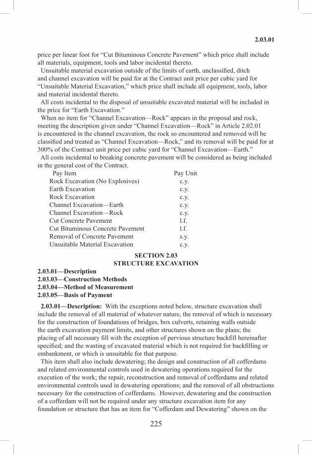
225
2.03.01
price per linear foot for “Cut Bituminous Concrete Pavement” which price shall include all materials, equipment, tools and labor incidental thereto. Unsuitable material excavation outside of the limits of earth, unclassified, ditch and channel excavation will be paid for at the Contract unit price per cubic yard for “Unsuitable Material Excavation,” which price shall include all equipment, tools, labor and material incidental thereto. All costs incidental to the disposal of unsuitable excavated material will be included in the price for “Earth Excavation.” When no item for “Channel Excavation—Rock” appears in the proposal and rock, meeting the description given under “Channel Excavation—Rock” in Article 2.02.01 is encountered in the channel excavation, the rock so encountered and removed will be classified and treated as “Channel Excavation—Rock,” and its removal will be paid for at 300% of the Contract unit price per cubic yard for “Channel Excavation—Earth.” All costs incidental to breaking concrete pavement will be considered as being included in the general cost of the Contract.
Pay Item Pay UnitRock Excavation (No Explosives) c.y. Earth Excavation c.y. Rock Excavation c.y. Channel Excavation—Earth c.y. Channel Excavation—Rock c.y. Cut Concrete Pavement l.f. Cut Bituminous Concrete Pavement l.f. Removal of Concrete Pavement s.y.Unsuitable Material Excavation c.y.
SECTION 2.03STRUCTURE EXCAVATION
2.03.01—Description2.03.03—Construction Methods2.03.04—Method of Measurement2.03.05—Basis of Payment
2.03.01—Description: With the exceptions noted below, structure excavation shall include the removal of all material of whatever nature, the removal of which is necessary for the construction of foundations of bridges, box culverts, retaining walls outside the earth excavation payment limits, and other structures shown on the plans; the placing of all necessary fill with the exception of pervious structure backfill hereinafter specified; and the wasting of excavated material which is not required for backfilling or embankment, or which is unsuitable for that purpose. This item shall also include dewatering; the design and construction of all cofferdams and related environmental controls used in dewatering operations required for the execution of the work; the repair, reconstruction and removal of cofferdams and related environmental controls used in dewatering operations; and the removal of all obstructions necessary for the construction of cofferdams. However, dewatering and the construction of a cofferdam will not be required under any structure excavation item for any foundation or structure that has an item for “Cofferdam and Dewatering” shown on the

226
2.03.03
plans and in the proposal estimate for a given location. In such instances, the provisions of Section 2.04 shall govern for the items described in 2.03.05 (b) below. “Structure Excavation—Earth” and “Structure Excavation—Rock” are defined as follows: 1. “Structure Excavation—Earth” shall include removal of all materials, other than water or “Structure Excavation—Rock.” 2. “Structure Excavation—Rock” shall include the removal of rock in definite ledge formation; boulders or portions of boulders that have a volume of 1 c.y. or greater; and masonry structures of 1 c.y. or more in volume, except retaining walls and bridge substructures, the removal of which is covered by Section 9.74.
2.03.03—Construction Methods: 1. Dimensions and Elevations of Footings: The elevations of the bottom of footings, as shown on the plans, shall be considered as approximate only, and the Engineer may order, in writing, such changes in dimensions or elevations of footings as may be necessary to secure a satisfactory foundation. 2. Preparation of Foundations: All rock or other suitable foundation material shall be cleared of all overlying material, cleaned and cut to a firm surface, either level, stepped or serrated, as directed by the Engineer. All seams shall be cleaned out and filled with concrete, mortar or grout. Any over-breakage in rock more than 6 in below the plan grade for the bottom of the footing not authorized by the Engineer shall be replaced by the Contractor with Class “A” Concrete at the Contractor’s expense. When the structure is to rest on a material other than rock, special care shall be taken not to disturb the material below the bottom of the excavation, and the final removal of the foundation material to grade shall not be made until just before the forms for concrete or masonry are placed. Any foundation material disturbed below plan grade or revised plan grade shall be dressed and compacted at the Contractor’s expense. This shall not apply, however, when a granular fill foundation course is required. 3. Cofferdams: If a cofferdam is required under this item, it will be designed and constructed in accordance with the provisions of Subarticles 2.04.03-1 and 2.04.03-3. 4. Dewatering: If a cofferdam is required under this item, dewatering will be performed in accordance with the provisions of Subarticle 2.04.03-2. 5. Inspection: After each excavation is completed, the Contractor shall notify the Engineer and no construction shall be started until the Engineer has approved the depth of the excavation and the character of the foundation material. 6. Fill Adjacent to Structures: All spaces excavated and not occupied by the abutments, piers, other permanent work or pervious structure backfill shall be filled to the surface of the surrounding ground with suitable material. Such backfill shall be thoroughly compacted and neatly graded. Fill placed around arches, rigid frames, box culverts and piers shall be deposited on both sides of the structure to approximately the same elevation at the same time. Each layer of backfill shall be spread to a thickness not exceeding 6 in deep after compaction and shall be thoroughly compacted by the use of power rollers or other motorized vehicular equipment, by tamping with mechanical rammers or vibrators, or by pneumatic tampers. Any equipment not principally manufactured for compaction purposes or which is not in proper working order in all respects shall not be used within the area described above.

227
2.03.05
Special attention shall be given to compaction in places close to walls where motorized vehicular compaction equipment cannot reach. Within 3 ft of the back face of walls and within a greater distance at angle points of walls, each layer of backfill shall be compacted by mechanical rammers, vibrators or pneumatic tampers. The dry density of each layer of backfill after compaction shall not be less than 95% of the dry density for that material when tested in accordance with AASHTO T 180, Method D. In conducting this test, material retained on the 3/4-in sieve size shall be replaced with material retained on the No. 4 sieve, as noted as an option in the specifications for this test. Adequate provision shall be made for the drainage of all fill in accordance with the provisions of the plans, or as ordered by the Engineer. Each layer of backfill shall be compacted at optimum moisture content. No subsequent layer shall be placed until the specified compaction is obtained for the previous layer. No fill shall be placed against any structure until the Engineer has given permission to do so and in no case until after the permitted time for removal of forms.
2.03.04—Method of Measurement: The Contractor shall notify the Engineer before starting any excavation, so that elevations and the measurements of the excavation area may first be obtained. When ledge rock is encountered, the Contractor shall notify the Engineer and shall strip or expose the rock to such an extent that in the Engineer’s opinion the necessary measurements can be taken for “Structure Excavation—Rock.” If the Contractor fails to give such notice(s), or removes any material prior to the taking of measurements, the Engineer may presume that measurements taken at the time the Engineer first saw the material in question indicates the true quantity of excavation. Vertical payment limits will be measured for payment as follows: 1. Structure Excavation—Earth will be measured in place by taking the difference in elevation between the existing ground surface or the bottom of roadway excavation or channel excavation, whichever is lower, and the surface of the completed structure excavation at plan grade or approved revised plan grade. Structure excavation in roadway cuts, or embankment areas where the removal of unsuitable material is indicated on the plans, shall include only the portion below the bottom of the unsuitable material or subbase, if any, or the subgrade, shoulder foundation or cut slope lines, as the case may be or as may be more specifically shown on the plans. 2. Structure Excavation—Rock will be measured in place by taking the difference in elevation between the existing ledge rock or bottom of roadway excavation or channel excavation, whichever is lower, and the bottom of the actual completed and accepted structure excavation, except that any excavation to a depth greater than 6 in below the plan grade or revised plan grade, will not be measured for payment. Horizontal payment limits for “Structure Excavation—Earth” and “Structure Excavation—Rock” will be measured between plumb lines 2 ft outside of the neat lines of the original foundations only, unless otherwise shown on the plans and unless the size of the footing is increased more than 2 ft in length or width (or both), in which case the area of the excavation that extends beyond the original Contract payment limits, will be used for determining the additional amount of excavation.
2.03.05—Basis of Payment: Payment for this work will be made at the Contract unit price per cubic yard for: (a) “Structure Excavation—Earth (complete)” or “Structure Excavation—

228
2.04.01
Rock (complete),” whichever applies, in whole or in part, which price shall include all materials, tools, and equipment; all work related to cofferdams, including their design, construction, dewatering, repair, removal of obstructions, and any required reconstruction; all labor necessary to complete the excavation in accordance with the requirements of the plans or as ordered by the Engineer; the preparation of foundations as described under Article 2.03.03; all necessary filling, except as otherwise provided in the Contract; and the removal of all surplus or unsuitable material resulting from the excavations. Any suitable surplus material shall be placed in the embankments, if so ordered by the Engineer, without additional compensation. (b) “Structure Excavation—Earth (Excluding Cofferdam and Dewatering)” or “Structure Excavation—Rock (Excluding Cofferdam and Dewatering),” whichever applies in whole or in part, which price shall include all materials, tools, equipment and labor necessary to complete the excavations in accordance with the requirements of the plans or as ordered by the Engineer. It shall also include the preparation of foundations as described under Article 2.03.03, the necessary filling, except as otherwise provided in the Contract, and the removal of all surplus or unsuitable material resulting from the excavations. Any suitable surplus material shall be placed in the embankments, if so ordered by the Engineer, without additional compensation. Should it become necessary to change the dimensions of the footings from those shown on the plans or to excavate below the elevation shown on the plans, payment will be made in accordance with the following provisions:1. The length or width (or both) may be increased horizontally not more than 2 ft and
the depth of excavation increased not more than 2 ft without change in the unit price as specified above.
2. If the depth of the excavation is increased more than 2 ft, but not more than 10ft below the original plan grade, payment for excavation below an elevation 2 ftbelow the elevation shown on the plans and within the horizontal payment limits asspecified above, will be at the Contract unit price plus 100% thereof.
3. When the size of the footing is increased horizontally more than 2 ft in length orwidth, or both, excavation actually required outside the horizontal payment limitsdefined above will be paid for at the Contract unit price plus l00% thereof.
4. In the event the depth of the excavation has to be increased to a depth greater than10 ft below the original plan elevation, the excavation actually made below the 10-ft limit will be considered extra work and will be paid for in accordance with Articlel.04.05.
Pay Item Pay UnitStructure Excavation—Earth (Complete) c.y.Structure Excavation—Rock (Complete) c.y.Structure Excavation—Earth (Excluding Cofferdam and Dewatering) c.y.Structure Excavation—Rock (Excluding Cofferdam and Dewatering) c.y.
SECTION 2.04COFFERDAM AND DEWATERING
2.04.01—Description: Work under this item shall consist of the design and construction of cofferdams as and where shown and specifically designated as such on

229
2.04.03
the plans; necessary dewatering, adjustments, repair or reconstruction; and the removal of temporary cofferdams and related facilities.
2.04.03—Construction Methods: 1. Cofferdams: Cofferdams shall be carried to adequate depths and heights, shall comply with Section 1.10, and shall be safe and watertight as necessary for the proper performance of the work which must be done inside them. Cofferdams shall be constructed so that the work can be safely carried to an elevation 2 ft lower than the elevation shown on the plans for the bottom of the structure footing, or, if a granular fill foundation is shown on the plans, to an elevation 2 ft lower than the bottom of the granular fill foundation. The interior dimensions of the cofferdams shall be sufficient for the unobstructed and satisfactory completion of all necessary substructure work, such as pile driving, form building, inspection and pumping. Cofferdams which become tilted or displaced prior to the completion of all work to be done within them, shall be righted, reset, or enlarged as may be necessary to provide the clearance for the unobstructed performance of all necessary work, and such corrections and adjustments of cofferdams shall be at the sole expense of the Contractor. Cofferdams shall be completely dewatered as required to complete the work entirely in the dry, except as specified below. When conditions are encountered that render it impractical to dewater the cofferdam, the Engineer may require the placing of underwater concrete of such dimensions as will be necessary to allow the Contractor to complete the substructure in the dry. The placement of underwater concrete shall comply with Subarticle 6.01.03-6. Cofferdams must be constructed to protect uncured masonry and concrete against damage from a sudden rising of the water and prevent damage to structure foundations by erosion. No part of the cofferdam which extends into the substructure may be left in place without written permission from the Engineer. At least 30 calendar days prior to the start of constructing or installing a cofferdam, the Contractor shall submit to the Engineer detailed plans and computations of its proposed cofferdam(s) prepared by a professional Engineer licensed in the State. The furnishing of such plans and methods shall not serve to relieve the Contractor of its responsibility for the safety of the work and the successful completion of the Project. The Contractor’s proposal must meet all requirements established in regulatory permits for the Project and must also meet the requirements of Section 1.10. 2. Dewatering: Pumping from the interior of any cofferdam shall be done in such a manner as to preclude the possibility of water moving through uncured masonry or concrete. During the placement of concrete or masonry, and for at least 24 hours thereafter, any pumping shall be done from a suitable sump located outside the horizontal limits and below the elevation of the work being placed or as directed by the Engineer. The pumped water must be discharged in accordance with the requirements of Section 1.10. Pumping to dewater a cofferdam shall not start until any underwater concrete has sufficiently set to withstand the hydrostatic pressure created by pumping. 3. Removal of Cofferdams: Unless the Engineer directs otherwise, the Contractor shall remove all parts of the cofferdam after completion of the required work. This shall be done in such a way as not to disturb or otherwise damage any permanent construction. Sheet piling used in constructing the cofferdam may be left in place with the approval of the Engineer, provided the piling is cut off at elevations approved in advance by the Engineer, and the cut off portions are removed from the Site.

230
2.04.05
2.04.04—Method of Measurement: Work under this item will be measured for payment by the number of linear feet of cofferdam designated numerically on the plans.
2.04.05—Basis of Payment: Payment for this work will be made at the Contract unit price per linear foot for “Cofferdam and Dewatering,” measured as described above, which price shall include all costs of design, materials, equipment, labor, work, and any related environmental controls used in dewatering operations, which are required for the construction of cofferdams shown in the plans; of any repair, correction, adjustment or reconstruction of such cofferdams required by the plans; removal of obstructions; pumping and dewatering; removal of such cofferdams and related environmental controls used in dewatering operations. If the Engineer requires the Contractor to construct an additional cofferdam not shown on the plans, or to enlarge a cofferdam beyond the dimensions of same as designated on the plans, or if the Engineer accepts the Contractor’s proposal to do so as being essential for the purposes of the Contract, the Department will revise the Contract to indicate those changes and to designate the revised dimensions of cofferdam deemed necessary by the Engineer. If the total number of linear feet of any given cofferdam as designated in the revised Contract is greater than the quantity as designated on the original Contract plans, the Department will pay the Contractor for the revised quantity of such linear feet at the Contract unit price, subject to the provisions of Articles 1.04.02 and 1.04.03. To the extent that the Engineer allows the addition or enlargement of a cofferdam for the convenience or other benefit of the Contractor, but does not deem that addition or enlargement essential for the performance of the Contract work, the Department will make no additional payment for the cofferdam or portion of the cofferdam which the Engineer does not so deem essential. The Department will not in any event pay the Contractor for fewer linear feet of a cofferdam than were designated on the original Contract plans unless the Department eliminates that cofferdam in its entirety from the Contract. Even if, however, the Contractor’s plan for an additional cofferdam or enlargement of a cofferdam deemed essential by the Engineer includes a previously-existing structure, in no case will a previously-existing natural or built structure, such as an abutment or an embankment, be measured for payment in calculating the revised number of linear feet of cofferdam on the Project. Any common cofferdam wall required for staged construction will be measured for payment only once. In no case will a given length or portion of cofferdam be measured for payment purposes more than once.
Pay Item Pay UnitCofferdam and Dewatering l.f.

231
2.05.03
SECTION 2.05TRENCH EXCAVATION
2.05.01—Description2.05.03—Construction Methods2.05.04—Method of Measurement2.05.05—Basis of Payment
2.05.01—Description: Trench excavation shall consist of the removal and satisfactory disposal of all materials, the removal of which is necessary for the proper completion of the work, to the dimensions shown on the plans or as ordered, and backfilling, all in accordance with these specifications for the following:1) The construction of pipe culverts, endwalls, catch basins, drop inlets, manholes,
underdrains and outlets, sewers, service pipes.2) The removal of storm water drainage structures, storm water pipes and
appurtenances beyond the limits of the roadway and structure excavation.3) The removal of miscellaneous items such as abandoned underground tanks,
pipelines, etc. Classification: (1) Trench excavation will be allowed only for the construction of the structures and
the removals definitely specified above; and no compensation will be made for any other class of excavation, as specified elsewhere herein, that may be necessary for construction or removal.
(2) Rock in Trench: Rock, insofar as it applies to trench excavation, shall be defined as rock in definite ledge formation, boulders, or portions of boulders, cement masonry structures, concrete structures, reinforced concrete pipe, Portland cement concrete pavement or base, of 1/2 c.y. or more in volume, removed as indicated or directed from within the payment lines for trench excavation.
2.05.03—Construction Methods: Trench excavation shall be made in accordance with the requirements of the plans or as ordered. The Contractor shall furnish and employ such shores, braces, pumps, etc., as may be necessary for the protection of property, proper completion of the work and the safety of the public and employees of the Contractor and the Department. All bracing, etc., shall be removed when no longer required for the construction or safety of the work. When a drainage structure is to be eliminated, it shall be completely removed and all pipes plugged with cement masonry or removed completely. Where the plans or Contract show that a drainage structure is to be abandoned, the structure shall be removed to a depth 2 ft below the subgrade or to the depth shown on the plan. The floor of the structure shall be broken and all pipes shall be plugged with cement masonry. Wherever portions of existing concrete pavement that would otherwise remain in place must be removed in conjunction with trench excavation, such removals shall be made to neat lines. The areas in which such concrete pavements are to be removed will be delineated by the Engineer before such work is done. Where no break or joint exists in the concrete pavement at the line of delineation, a full depth cut shall be made in the concrete with a concrete cutting saw approved by the Engineer. The concrete shall then be removed from within the delineated area, exercising extreme care to avoid

232
2.05.04
“breakbacks” beyond the sawcut or joint. Concrete pavement remaining in place shall have vertical edges. Wherever the concrete pavement to be removed has been overlaid with bituminous concrete and the adjacent bituminous concrete pavement is to remain in place, the bituminous pavement shall be removed to a neat line that is 1 ft beyond the neat line for the concrete pavement removal. Wherever portions of existing full-depth bituminous concrete pavement are to be removed in conjunction with trench excavation, they shall be removed to neat lines. Where the limits of the areas in which such bituminous pavement is to be removed are adjacent to existing bituminous concrete pavement that is to remain in place, the limits shall be cut by a method approved by the Engineer. After the excavation is completed, the Contractor shall notify the Engineer; and no masonry, pipe or other material shall be placed in the excavated area until the Engineer has approved the depth of excavation and the character of the foundation material. When backfilling is required, the material used shall be of a quality satisfactory to the Engineer and shall be free from large or frozen lumps, wood and other extraneous material. All backfill shall be placed in layers of not more than 6 in deep after compaction and shall be thoroughly compacted by means of mechanical rammers or vibrators or by pneumatic tampers. Hand tampers shall be used only upon written permission of the Engineer. Unless otherwise ordered by the Engineer, the backfill shall be brought to the surface of the surrounding ground and neatly graded. All suitable material removed in making the excavation shall be used for backfill if required. All surplus or unsuitable material shall be removed and disposed of as directed. Should additional material be required for backfilling, it may be obtained from the Project excavation or from borrow pits, gravel pits, or elsewhere as the Engineer may direct. Each layer of backfill shall be compacted to optimum moisture content. No subsequent layer shall be placed until the specified compaction is obtained for the previous layer. Fill placed around pipes shall be deposited on both sides to approximately the same elevation at the same time. Rock fill or stones larger than 2 in shall not be placed closer than 2 ft from the pipes on the sides and the top. No backfill shall be placed against any structure until permission has been given by the Engineer.
2.05.04—Method of Measurement: Except as noted below, the depth of trench excavation will be measured in its original position by taking the difference between the ground surface at the time the trench is excavated and that after the excavations are complete. Before starting any excavation, the Contractor shall notify the Engineer so that elevations and measurements of the work may be obtained. Any work done prior to such notification will not be paid for. Trench excavation in roadway cuts will include only that portion outside of the limits of roadway excavation and will not include open ditches. Payment limits will be as described hereinafter. There will be no measurement for payment for the cost of plugging existing pipes. Horizontal Payment Limits: Except as noted below for installations of pipe and pipe arches, fabricated from structural plates, payment lines will be vertical for pipe culverts, pipe-arches, sewers, and service pipes, and will be the width to which the material is actually removed, except that in no case, even though the actual excavation is wider, will

233
2.05.04
the width between payment lines be more than the following: (a) 2 ft greater than the nominal inside diameter of circular pipe, or nominal inside
span of elliptical pipe or pipe-arch for such diameters or spans of less than 30 in. (b) 3 ft greater than the nominal inside diameter of circular pipe or the nominal inside
span of elliptical pipe or pipe-arch for such diameters or spans that are 30 in or greater.
For pipes and pipe‑arches, fabricated from structural plates specified in Subarticle M.08.01-5, payment lines will be vertical and between the actual horizontal limits to which the material is removed except that the width between payment lines will not be more than 4 ft greater than the nominal inside diameter or nominal horizontal inside span. For endwalls, manholes, drop inlets and catch basins, payment lines will be vertical and 2 ft outside of the neat lines of the foundations in each direction horizontally. In case it is necessary to excavate to a greater width than that specified above due to of the removal of existing structures, such additional excavation will be considered as trench excavation and will be measured and paid for as such. For the removal of underground obstructions such as pipelines, tanks, drainage structures, etc., payment lines shall be vertical and 2 ft outside of the underground item measured horizontally in each direction. If rock is encountered, the Contractor shall strip it of sufficient overlying material to allow for proper measurement and shall then notify the Engineer that the rock surface is ready for measurement. If the Contractor shall fail to give such notice, the Engineer will presume that the measurements taken at the time the Engineer first saw the material in question will give the true quantity of excavation. Vertical Payment Limits: Where pipe bedding is used, the lower vertical payment limit will be as shown on the plans. There will be no direct payment for the excavation necessitated by the shaping of the bedding, but the cost shall be included in the cost per linear foot for the pipe culvert specified. The upper vertical payment limit will be that prescribed below; except, when in the opinion of the Engineer, roadway excavation cannot be made prior to or simultaneously with the trench excavation, then the upper vertical payment limit will be the surface existing at the time the trench excavation is made. Vertical Payment Limits Other Than in Fills: Payment lines will extend vertically from the bottom of the trench to the bottom of the roadway excavation. If trench excavation is not located within the limits of roadway excavation, payment lines will extend vertically from the bottom of the trench to the existing ground surface. Vertical Payment Limits in Fills: For the various drainage installations, the vertical payment lines will extend from the bottom of the completed and accepted trench to the lowest of the following upper limits: a. Bottom of subbase. b. In the case of culverts, 1 ft above the top of the pipe. c. In the case of drainage structure other than culverts, 1 ft above the top of the
uppermost culvert pipe placed in the structure. d. In the case of culvert installations transverse to the roadway extending down
fill slopes, the vertical payment limit will be the depth below bottom of loam or embankment surface, as the case may be, and measured perpendicular to the bottom of the trench.

234
2.05.05
Vertical payment limits will be as described above except that in no case will the depth measurement used for payment be greater than that actually excavated. If gravel fill or borrow are used for trench backfill, they will be measured in place within the payment limits described herein. Trench excavation will not be measured for payment for resetting manholes, catch basins, drop inlets, junction boxes or utility structures and appurtenances, but the cost will be included in the payment for the specified reset item. The work of cutting concrete pavement and cutting bituminous concrete pavement will be measured in accordance with Article 2.02.04.
2.05.05—Basis of Payment: This work will be paid for at the Contract unit price per cubic yard for “Trench Excavation 0 feet - 4 feet Deep,” “Trench Excavation 0 feet - 10 feet Deep,” “Trench Excavation 0 feet - 15 feet Deep” or “Trench Excavation 0 feet - 20 feet Deep,” as the case may be. When rock, meeting the description given under Article 2.05.01 is encountered within the payment lines for trench excavation, its removal will be classified and paid for at the Contract unit price per cubic yard for “Rock in Trench Excavation 0 feet - 4 feet Deep,” “Rock in Trench Excavation 0 feet - 10 feet Deep,” “Rock in Trench Excavation 0 feet - 15 feet Deep” or “Rock in Trench Excavation 0 feet - 20 feet Deep,” as the case may be. Those portions of trench excavation classified and paid for as “Rock in Trench Excavation” of the various depths will be the actual volumes of rock excavated within the payment lines at the applicable bottom depth. Those portions of trench excavation above the rock will be the actual volume of earth excavated within the payment lines at the applicable bottom depth for rock in trench. Where no item or items for “Rock in Trench Excavation” at the applicable depth appear in the proposal and rock is encountered in trench excavation, its removal will be paid for as follows: a. In trench excavation 0 feet - 4 feet deep, at 500% of the Contract unit price for
“Trench Excavation 0 feet - 4 feet Deep.” b. In trench excavation 0 feet - 10 feet deep, at 400% of the Contract unit price for
“Trench Excavation 0 feet - 10 feet Deep.” c. In trench excavation 0 feet - 15 feet deep, at 300% of the Contract unit price for
“Trench Excavation 0 feet - 15 feet Deep.” d. In trench excavation 0 feet - 20 feet deep at 150% of the Contract unit price for
“Trench Excavation 0 feet - 20 feet Deep.” When payment is made for trench excavation in fill, no such excavation will be classified as “Rock in Trench.” Excavation necessary for the removal of pipe culverts, or other installations, described herein, will be paid for as trench excavation at the applying depth. The above prices shall include all materials, tools, equipment and labor necessary to complete the excavation in accordance with the plans or as ordered. The prices shall also include backfilling where required and the disposal of surplus material. No additional payment will be made for shoring, bracing, pumping, bailing or for material or equipment necessary for the satisfactory completion of the work. When it becomes necessary, in the opinion of the Engineer, to install sheet piling for the support of existing facilities, pavement, utilities, or for other constraints, the sheeting items will be paid in accordance with Section 7.13, 7.14 or 7.15.

235
2.05.05
If gravel fill or borrow are used for trench backfill, payment will be made at their respective Contract unit prices, or in the absence of such items in the Contract, as extra work. There will be no direct payment for the plugging of existing pipes, removal and disposal of metal or plastic pipes or for the breaking up of floors in drainage structures being abandoned. The cost shall be included in the Contract unit prices of the drainage and excavation items. Payment for the work of “Cut Concrete Pavement” and “Cut Bituminous Concrete Pavement” will be made in accordance with Article 2.02.05 except that the cut made in the bituminous concrete overlay 1 ft beyond the neat line for concrete pavement removal is not included under “Cut Concrete Pavement” and will be paid for as “Cut Bituminous Concrete Pavement.”
Pay Item Pay UnitTrench Excavation ( ) Deep c.y. Rock-in-Trench Excavation ( ) Deep c.y.

236
2.06.01
SECTION 2.06DITCH EXCAVATION
2.06.01—Description: Ditch excavation shall consist of the removal and satisfactory disposal of all materials except water, the removal of which is necessary for the construction of drainage ditches, paved ditches, and paved leak-offs, except as noted below. Not included herein is excavation for gutters and channels.
2.06.03—Construction Methods: Ditch excavation shall be made in accordance with the requirements of the plans or as ordered by the Engineer. The excavated material shall be removed from the area adjoining the excavation and the suitable excavated material used in the embankments, unless otherwise directed by the Engineer. Unsuitable materials shall be disposed of as directed. The top of the banks of the ditches shall be graded and left in a neat and acceptable condition.
2.06.04—Method of Measurement: Ditch excavation will be measured for payment according to the conditions and between the limits set forth in the following: 1. Drainage Ditches (unpaved): (a) Within normal cut slopes, excavation will be measured under Section 2.02. (b) On fill slopes, between the surface of the embankment and the bottom of the
excavation. (c) In areas other than (a) and (b), above, between the original ground surface and that
after excavation is completed. 2. Paved Leak-offs and Paved Ditches: (a) Within normal cut slopes, between the limits of the top of paved surface and the
bottom of the base course. (b) Within normal fill slopes, between the surface of the embankment and the bottom
of the base course. (c) Outside of cut or fill slopes, between the ground surface and that after the
excavation is completed. Before starting any excavation, the Contractor shall notify the Engineer so that elevations and measurements of the work may be obtained. Any work done prior to such notification will not be paid for. If rock meeting the description given under Article 2.05.01 is encountered, the Contractor shall strip it of sufficient overlying material to allow for proper measurement. The Contractor shall notify the Engineer at least 2 days prior to disturbing the rock that the rock surface is ready for measurement. If the Contractor shall fail to give such notice, or remove any rock prior to the taking of such measurement, the Engineer shall presume that the measurements taken at the time the Engineer first saw the material in question will give the true quantity of excavation.
2.06.05—Basis of Payment: This work will be paid for at the Contract unit price per cubic yard for “Ditch Excavation” or “Rock in Ditch Excavation,” whichever may apply in whole or in part. These prices shall include all equipment, tools and labor necessary to complete the work, dispose of the excavated material and leave the Site in a neat and workmanlike condition. When no item for “Rock in Ditch Excavation” appears in the Contract and rock meeting the description given under Article 2.05.01 is encountered in ditch excavation, its removal will be paid for at 500% of the Contract unit price per cubic yard for “Ditch Excavation.”

237
2.07.03
Pay Item Pay UnitDitch Excavation c.y. Rock in Ditch Excavation c.y.
SECTION 2.07BORROW
2.07.01—Description: When the amount of usable material excavated within the limits of the work contracted for is not sufficient to form the embankments and other features of the work, additional material shall be furnished by the Contractor from borrow pits obtained at its expense and located beyond the limits of the highway. This material shall be known as borrow. Borrow shall include the furnishing, removing and satisfactory placing of the additional material necessary to complete the embankments and other features of the work. Stockpiled hydraulically dredged and/or reclaimed waste material containing no more than 25% of glass or clinker by weight and no more than 2% by weight of asphalt cement may be used for part or all borrow requirements. Stockpiles shall be placed at locations arranged for and provided by the Contractor at its expense and will not be allowed within the highway limits except at locations and under conditions stipulated by the Engineer. All permits, easements, rights or other requirements related to dredging and stockpiling shall be the obligation and responsibility of the Contractor.
2.07.02—Materials: Borrow, excluding hydraulically dredged borrow, shall meet the requirements of Article 2.02.03 for performance when incorporated in embankments. For purposes other than embankments, it shall be of a satisfactory quality as determined by the Engineer for the purpose intended. Hydraulically dredged borrow shall contain no more than 20% by dry weight of material passing the No. 200 sieve when placed in the embankment.
2.07.03—Construction Methods: Borrow will be permitted only to the extent necessary to complete the embankments and similar details and only after all usable material from the excavation has been placed. With the approval of the Engineer, the Contractor may be permitted to place borrow before the excavation is completed; but will be held responsible for the proper placing of all suitable excavated material, and no payment will be allowed for any borrow placed in lieu of suitable excavated material. This permission may be revoked by the Engineer at any time if in the Engineer’s opinion satisfactory progress is not maintained on other operations. The Contractor shall notify the Engineer at least 5 days prior to obtaining material from any borrow pits so that an examination may be made of the fitness of the material and so that the necessary measurements may be taken. The limits of the proposed borrow pit shall be shown to the Engineer; and prior to the taking of measurements, the Contractor shall be required to clear the area of all unsuitable material. No payment will be made for any material removed outside of the area measured or which was not used in the work. No excavation shall be made within the confines of a borrow pit after the Engineer has taken original measurements, other than for material to be used in the formation of embankments or elsewhere as shown on the plans or as directed by the Engineer; except that material may be taken for Contract items other than borrow with the permission of the Engineer under terms and conditions set forth in writing. If the Contractor elects to obtain borrow from a commercial pit, it shall be necessary

238
2.07.04
to have a section of the pit set off for the Contractor’s use solely, so that the amount of material removed may be accurately determined. During the period between the original and the final measurements and release by the Engineer, no material shall be taken from a measured borrow pit except by the Contractor for use in the work under this Contract. Borrow pits shall be excavated to regular lines as staked, so as to permit accurate measurements, and shall be drained and left in a neat condition as directed. If the Contractor elects to obtain borrow from a stockpile of reclaimed waste, approval shall be obtained from the Engineer prior to removing any material from the stockpile to the job Site. Once the stockpiles have been tested and approved, no additional material shall be added to them. If the Contractor uses hydraulically dredged material, the Contractor shall, at its expense, employ effective dust control measures so that the public will not be adversely affected by dust from stockpiled material or such material in transit. The Contractor shall also provide and maintain at its expense effective and adequate drainage for all dredging and stockpiling operations at all times, and shall be solely responsible for all damages which result from dredging and stockpiling and for the continuing maintenance and final restoration of all drainage facilities affected by its operations. Stockpiles of hydraulic material shall be reserved for exclusive use of the State and be placed so as to be readily measured, and no area shall be reused for stockpiling prior to its being re-measured by the Engineer. Dredging to a stockpile and removing material therefrom simultaneously is expressly prohibited. Borrow shall be placed where directed and in accordance with the provisions for the formation of embankments of Article 2.02.03.
2.07.04—Method of Measurement: Except as provided under (a), (b), (c), (d) and (e) below, the amount of borrow to be paid for will be determined by the average end area method, from the results of cross-sectional elevations taken before and after the borrow material has been excavated from the pit or stockpile. Measurements of stockpiles will not be taken until they are firm and can be measured safely and accurately. (a) If, in the opinion of the Engineer, cross-sections of the stockpiled hydraulically
dredged material will not indicate the true volume removed for borrow, supplementary measurements will be taken. This may involve the use of settlement platforms, trenches, test holes or other methods or any combinations thereof. The data so derived will be applied in the adjustment of the computation of the quantity for payment.
(b) At the request of the Engineer or with the written permission of the Engineer, borrow may be measured by the cubic contents of the vehicles used for transportation less a 10% shrinkage factor for earth or less an agreed upon shrinkage factor for rock to be determined by the Engineer.
(c) At the request of the Engineer or with the written permission of the Engineer, borrow may be weighed and such weight will be converted to cubic yards on the basis of 3200 lb./c.y.
(d) At the request of the Engineer or with the written permission of the Engineer, the volume of borrow used to construct embankment may be measured in place. The shrinkage factor for earth shall be 10%. The swell factor for rock shall be determined by the Engineer.
(e) At the request of the Engineer or with the written permission of the Engineer,

239
2.08.03
the Contractor may remove material from the borrow pit for purposes other than the formation of embankments, in which event the method of adjusting borrow measurements will be stated in the authorization.
2.07.05—Basis of Payment: Payment for this work will be at the Contract unit price per cubic yard for “Borrow” complete in place, which price shall include furnishing and placing the material and all equipment, tools and labor necessary thereto. No payment will be allowed for “Borrow” until all excavation has been placed in embankments except under the following conditions: If the Contractor has secured the permission of the Engineer to place borrow before the excavation is complete, as provided for in Paragraph 1 of Article 2.07.03, payment for such borrow material may be made at the discretion of the Engineer, before completion of the excavation. A request for such payment shall be made by the Contractor in writing, certifying therein that it waives payment for any borrow placed in lieu of suitable excavated material. Deductions will be made from borrow measurements for any materials wasted from the cuts or placed in embankments outside of the cross-sections, except when unsuitable material is ordered to be wasted by the Engineer.
Pay Item Pay UnitBorrow c.y.
SECTION 2.08FREE-DRAINING MATERIAL
2.08.01—Description: Free-draining material shall consist of material meeting the requirements stated elsewhere herein. This material shall be furnished and placed in accordance with these specifications and as indicated on the plans, special provisions, or as ordered by the Engineer for the stabilization or embankments, or for fill in free water areas, or wherever specified.
2.08.02—Materials: Material for this work shall meet the requirements of Article M.02.07.
2.08.03—Construction Methods: The Contractor shall notify the Engineer at least 3 days prior to obtaining free-draining material from any source so that an examination may be made of the material and the necessary measurements may be taken. The limits of the proposed source shall be shown to the Engineer; and prior to the taking of measurements, the Contractor shall be required to clear the area of all unsuitable material. No payment will be made for any material removed outside of the area measured or which was not used in the Contract work. No excavation shall be made within the confines of a source after the Engineer has taken the original measurements, except for material to be used for the purposes hereinbefore indicated, except with the permission of the Engineer. The Contractor may, with the approval of the Engineer, obtain free-draining material, if available, from within the roadway excavation limits subject to the provisions of Article 1.04.07. If the Contractor elects to obtain free-draining material from a commercial pit, it will be necessary to have a section of the pit set off for its use solely, so that the amount of material removed may be accurately determined. During the period between the original and the final release by the Engineer, no material shall be taken from a measured pit except by the Contractor and for use only in the work under the Contract.

240
2.08.04
If the Contractor elects to use stone from a quarry or reclaimed miscellaneous aggregate, the Contractor shall use only the materials from stockpiles which have been approved for use. Free-draining material will be permitted only to the extent necessary to construct embankments to 3 ft above free water, or to promote free drainage in areas specified on the plans, in the special provisions, or as directed by the Engineer. Free-draining material shall be placed in accordance with the provisions for the formation of embankment of Section 2.02.
2.08.04—Method of Measurement: The amount of free-draining material to be paid for will be determined by the average end area method based on the results obtained from cross-sectional elevations taken before and after the free-draining material has been excavated. When material is drawn from a quarry stockpile or stockpile formed from reclaimed miscellaneous aggregate, the material shall be weighed on scales furnished by and at the expense of the Contractor. The scales shall be of a type satisfactory to the Engineer and shall be sealed at the expense of the Contractor as often as the Engineer may require. All weighing shall be done in the presence of a representative of the Department. From the weight so obtained, the volume shall be computed based on a specific gravity of 2.92 for the aggregate and smaller particles. For material having a different specific gravity, an appropriate correction shall be made.
2.08.05—Basis of Payment: Payment will be made at the Contract unit price per cubic yard for “Free-Draining Material,” complete in place, which price shall include furnishing and placing the material and all equipment, tools and labor necessary thereto.
Pay Item Pay UnitFree-Draining Material c.y.
SECTION 2.09SUBGRADE
2.09.01—Description: The area upon which the pavement structure and paved shoulders are placed, including the shoulder base courses and subbase shall be known as the subgrade. This is the plane coincident with the bottom of the subbase and the edge of pavement, as shown on the plans and cross-sections or as ordered by the Engineer. The work of formation of subgrade shall be performed at this plane. Where precast concrete barrier curb is to be permanently installed, the work of formation of subgrade shall be performed on the area under the precast concrete barrier curb. Where shoulders are to be reconstructed and the existing subbase is to remain, the work of formation of subgrade shall be performed at the plane coincident with the surface of the existing subbase. After all grading has been substantially completed and all drains laid, the subgrade shall be brought to the lines, grades and cross-sections shown on the plans. When no item for “Clearing and Grubbing” and no grading items appear in the proposal, the work of clearing waterways, ditches, drainage structures and culverts, as described in Article 2.01.03, shall be performed as part of this work.
2.09.03—Construction Methods: All soft and yielding material and other portions of

241
2.09.05
the subgrade which will not compact readily shall be removed and replaced with suitable material. In cut areas, the surface shall be uniformly compacted by use of equipment specifically manufactured for that purpose. Rollers shall deliver a ground pressure of not less than 300 lb./in of contact width and weigh not less than 10 tons. Vibratory units shall have a static weight of not less than 4 tons. The amount of compactive effort shall be as directed by the Engineer, but shall be at least 4 complete passes of the compacting equipment being used. The dry density after compaction shall be as specified in Subarticle 2.02.03‑6. Where multiple compacting units are to be used, that unit which exerts the larger compactive effort shall make the initial passes. Any portion of the subgrade not accessible to larger compacting units shall be compacted, as directed by the Engineer, to a degree equal to that obtained on the other portions of the subgrade with equipment and by methods appropriate to the size of the inaccessible area. After compacting, the subgrade shall be true to required line and grade. There will be no direct payment for any materials required to bring the subgrade to the line, grade and cross-section shown on the plans. The Contractor shall protect the completed subgrade from damage by exercising such precautions as the Engineer deems necessary. The subgrade surface shall be maintained in such condition as to permit proper drainage. It shall be checked and approved by the Engineer prior to placing any pavement structure and shoulders thereon.
2.09.04—Method of Measurement: Payment lines for formation of subgrade will be coincident with the outside edges of the pavement or where paved shoulders are constructed, with the outside edges of the shoulder. Where precast concrete barrier curb is permanently installed, measurement for payment will include the area under the precast concrete barrier curb. Payment for formation of subgrade will be allowed when such work is done in providing connections to public roads. Payment for formation of subgrade will not be allowed for work at private drives, in areas where traffic bound gravel is constructed or in areas where existing pavement is used as a base for resurfacing with bituminous concrete. The area computed for payment will not include the area of any bridge floor where the type of construction is such as to eliminate any necessity for the work described herein.
2.09.05—Basis of Payment: Formation and protection of subgrade, including all work provided for hereinbefore, will be paid for at the Contract unit price per square yard for “Formation of Subgrade,” which price shall include all materials, equipment, tools and labor necessary thereto. There will be no specific payment for the work of scarifying existing stone or gravel roads as described in Article 2.02.03, but the cost of such work shall be considered included in the payment for the item providing for the formation of subgrade. When no item for “Formation of Subgrade” appears in the proposal, the cost of this work shall be included in the Contract unit price for the pavement item or items involved.
Pay Item Pay UnitFormation of Subgrade s.y.

242
2.10.01
SECTION 2.10WATER POLLUTION CONTROL (SOIL EROSION)
2.10.01—Description: This work shall consist of measures to control water pollution and soil erosion through the use of berms, dikes, dams, sediment basins, erosion control matting, gravel, mulches, grasses, slope drains, ditches, channels, riprap, grading to control surface runoff and other erosion control devices or methods. If the Contractor proposes changes in construction or scheduling which would affect the designed pollution controls, plans for revised pollution controls shall be submitted for the Engineer’s approval before starting construction. The Contractor shall submit a plan showing erosion and sedimentation controls above and beyond those called for in the plans and specifications, necessitated by its proposed sequence of operations and construction activities. The construction shall not proceed until the erosion and sedimentation control plans have been approved by the Engineer. The Engineer may order additional control measures if the measures mentioned above prove insufficient.
2.10.02—Materials: The materials shall consist of items meeting the pertinent articles of the Standard Specifications and approved by the Engineer, or other items approved by the Engineer, such as: (a) Soil tackifiers, erosion control matting, burlap, and plastic sheets. All materials
shall be clean and free from noxious weeds, contaminants, and debris deleterious to plant growth. Erosion control matting shall be as specified in Section M.13.
(b) Slope drains or ditches may be constructed of pipe, rubble, riprap, sod, burlap, plastic sheets, Portland cement concrete, bituminous concrete, or other material approved by the Engineer.
(c) Seeding shall be as specified in Sections 9.50 and M.13.
2.10.03—Construction Method: The Engineer has the authority to control the surface area of earth material exposed by construction operations and to direct the Contractor to immediately provide permanent or temporary pollution control measures to prevent contamination of adjacent streams, watercourses, lakes, ponds or other areas of water impoundment. Every effort shall be made by the Contractor to prevent erosion on the Site and abutting property. All slopes shall be stabilized by mulching, seeding or otherwise protected as the work progresses to comply with the intent of this specification. All seeding shall include mulch or other protective covering approved by the Engineer. When hay is used as a mulch with seeding, it shall be a minimum of 2 in deep and held down with a tackifier. When wood fiber mulch is used, it shall be applied in a water slurry at a rate of 2000 lb./ac with or immediately after the application of seed, fertilizer and limestone. All damaged slopes shall be repaired as soon as possible. The Engineer shall limit the surface area of earth material exposed if the Contractor fails to sufficiently protect the slopes to prevent pollution. The Contractor shall at all times have on hand the necessary materials and equipment to provide for early slope stabilization and corrective measures to damaged slopes. Temporary channels, ditches and outfalls shall be protected prior to directing water into them to prevent erosion.

243
2.10.05
The erosion control features installed by the Contractor shall be maintained by the Contractor, and such installations shall be removed if ordered by the Engineer. Maintenance of erosion control measures by the Contractor shall include the clean out of accumulated sediment. The Contractor shall operate all equipment and perform all construction operations so as to minimize pollution. The Contractor shall cease any of its operations which will increase pollution during rain storms. The Contractor shall give the Engineer sufficient notice of impending shutdowns to enable the Engineer and Contractor to examine the Project and to implement erosion and pollution control work.
2.10.04—Method of Measurement: Measurement for payment of work and materials involved with the construction, application and installation of water pollution controls will be as provided for under the applicable Contract items. Temporary slope protection will be measured for payment by the number of square yards of slope protected in accordance with this specification and as directed by the Engineer. When no applicable Contract item appears in the proposal for any additional measures not shown on the plans, the additional work and materials required for those measures shall be measured for payment as provided for under Article 1.09.04—Extra and Cost-Plus Work. All extra work performed on an agreed-price basis shall be incorporated through construction orders and paid for on an item-by-item basis. The sum of money shown on the estimate and in the itemized proposal as “Estimated Cost” for this work will be considered the price bid even though payment will be made only for actual work performed. The estimated cost figure is not to be altered in any manner by the bidder. Should the bidder alter the amount shown, the altered figures will be disregarded and the original price will be used to determine the total amount bid for the Contract.
2.10.05—Basis of Payment: Work will be paid for under the applicable Contract items or as provided for under Article 1.09.04—Extra and Cost-Plus Work. No payment will be made for the clean out of accumulated sediment for either permanent or temporary erosion control measures. Temporary pollution control measures that are made necessary by the Contractor’s negligence, carelessness, failure to install permanent controls as a part of the work as scheduled and are ordered by the Engineer, or are made necessary by the Contractor’s failure to perform the sequence and scheduling of work as part of the schedule as given in the Preconstruction Conference or as later amended and approved, will be ordered by the Engineer to be accomplished and performed by the Contractor at its own expense. On areas off the right-of-way that are selected by the Contractor and which include but are not necessarily limited to borrow pits (other than commercially operated sources), Contractor’s haul roads, disposal areas, storage, maintenance, batching areas, etc., temporary control work shall be the responsibility of the Contractor and shall be performed by the Contractor at its expense in a manner approved by the Engineer. No direct payment will be made for this work, the cost is to be included in other items of the Contract. Temporary control work on the aforesaid areas which are specifically designated for contractual operations by the State shall be paid for under the provisions of this specification.

244
2.11.01
Temporary slope protection will be paid for at the Contract unit price per square yard for “Temporary Slope Protection,” which price shall include the installation and removal, where necessary, of the protective material and all equipment, materials, tools and labor incidental thereto.
Pay Item Pay UnitWater Pollution Control est.Temporary Slope Protection s.y.
SECTION 2.11ANTI-TRACKING PAD
2.11.01—Description2.11.02—Materials2.11.03—Construction Methods2.11.04—Method of Measurement2.11.05—Basis of Payment
2.11.01—Description: This work shall consist of furnishing, installing, maintaining and removing a crushed stone anti‑tracking pad on geotextile filter fabric. All areas affected by the anti-tracking pad shall be restored to the original or plan contours. If shown on the plans or ordered by the Engineer, the restored areas shall be stabilized with turf establishment.
2.11.02—Materials: The crushed stone shall meet the grading requirements of Article M.01.01 for 2-in (No. 3) coarse aggregate. Geotextile filter fabric shall meet the requirements of Section 7.55 and Subarticle M.08.01-19. Topsoil, if necessary, shall meet the requirements of Article M.13.01. Seed, if necessary, shall meet the requirements of Article M.13.04. Fertilizer, if necessary, shall meet the requirements of Article M.13.03. Mulch, if necessary, shall meet the requirements of Article M.13.05.
2.11.03—Construction Methods: Clear area of anti-tracking pad of all vegetation and excavate to a minimum depth of 4 in. Place geotextile filter fabric over the full width and length of excavated area and cover with No. 3 crushed stone to a minimum depth of 4 in. The anti-tracking pad shall be uniformly graded to produce the entry and exit path to the Site for all construction equipment. The pad shall be maintained of sufficient grading and stone surface to capture all soils and sediment from equipment tires prior to such exiting from the Site. Crushed stone shall be replenished or replaced as necessary or as ordered by the Engineer to assure sufficient capture of sediment at the construction Site. Any sediment or crushed stone tracked off the Site shall be immediately cleaned, swept and removed by the Contractor at no cost to the State.
2.11.04—Method of Measurement: This work will be measured for payment by the number of square yards of accepted anti-tracking pad completed as shown on the plans or as ordered by the Engineer.
2.11.05—Basis of Payment: Payment for this work will be made at the Contract unit

245
2.12.04
price per square yard for “Anti-Tracking Pad,” which shall include furnishing and placing all material, including the geotextile; for maintaining the anti‑tracking pad during the Project construction period; for removing the anti‑tracking pad after completion of the Project; for restoring the Site, including any required turf establishment; and for all labor, equipment, tools, and incidentals required to complete the work as well as the cleaning and sweeping of any sediment or crushed stone tracked off the Site. Clearing and grubbing required to install the anti-tracking pad will be paid under the item “Clearing and Grubbing.” Pay Item Pay Unit Anti-Tracking Pad s.y.
SECTION 2.12SUBBASE
2.12.01—Description: The subbase shall consist of a clean soil-aggregate mixture of bank or crushed gravel, crusher run stone, reclaimed miscellaneous aggregate containing no more than 2% by weight of asphalt cement or any combinations thereof, placed where shown on the plans or where directed by the Engineer and constructed in accordance with these specifications.
2.12.02—Materials: All materials for this work shall meet the requirements of Articles M.02.02 and M.02.06.
2.12.03—Construction Methods: The prepared foundation for the subbase shall be carefully shaped to the required cross section and compacted as specified in Article 2.02.03. Where underdrains and outlets are specified on the plans or ordered by the Engineer, they shall be in place and functioning before any subbase material is placed. The subbase material shall be spread uniformly upon the required grade, in courses not to exceed 6 in thick after final compaction. However, if the required thickness of subbase does not exceed 8 in it may be placed in a single course. After each course has been placed as specified above, its entire area shall be compacted with equipment specifically manufactured for that purpose. The use of hauling and spreading equipment shall not be considered as a substitute for compacting equipment. Compaction shall be continued until the entire course is uniformly compacted to the required minimum density. The dry density after compaction shall not be less than 95% of the dry density for that subbase material when tested in accordance with AASHTO T 180, Method D. If a subbase course is formed from reclaimed miscellaneous aggregate containing bituminous concrete, the wet density after compaction on this course shall not be less than 95% of the wet density for that subbase when tested in accordance with AASHTO T 180, Method D. Each layer of subbase shall be compacted at optimum moisture content. No subsequent layer shall be placed until the specified compaction is obtained for the previous layer. Should the foundation material beneath the subbase become churned up and mixed with subbase material at any time, the Contractor shall, without additional compensation, remove the mixture and replace it with new subbase material to the required thickness shown on the plans or as previously required by the Engineer. Such replaced subbase material shall be compacted to the required minimum density.
2.12.04—Method of Measurement: Subbase will be measured horizontally in place

246
2.12.05
after final grading and compaction. The thickness will be as indicated on the plans, or as ordered by the Engineer, and within the following tolerances: Less than 24 in: minus 1 in to plus 3/4 in 24 in and greater: minus 2 in to plus 1 in Measurements to determine the thickness will be made by the Engineer at intervals of 500 ft, or less, along lanes and shall be considered as representative of the lane. For purposes of these measurements, a shoulder will be considered a lane. If deficient thicknesses are found, the Engineer will make such additional measurements considered necessary to determine the longitudinal limits of the deficiency. Areas not within allowable tolerances shall be corrected, as ordered by the Engineer, without additional compensation to the Contractor.
2.12.05—Basis of Payment: This work will be paid at the Contract unit price per cubic yard for “Subbase,” which price shall include all materials, equipment, tools and labor incidental thereto.
Pay Item Pay UnitSubbase c.y.
SECTION 2.13GRANULAR FILL
2.13.01—Description: This material shall be used as a foundation for structures, to replace unstable material in slopes, as a foundation for sidewalks and culverts, in shoulders and elsewhere as indicated on the plans, required by the specifications or ordered by the Engineer. It shall consist of gravel or reclaimed miscellaneous aggregate containing no more than 2% by weight of asphalt cement meeting the requirements of these specifications.
2.13.02—Materials: Granular fill shall meet the requirements of Article M.02.01.
2.13.03—Construction Methods: When granular fill is used for foundation for structures or to replace rock or unsuitable material in trenches, it shall be deposited in layers not over 6 in deep, with each layer thoroughly compacted before the addition of other layers.
2.13.04—Method of Measurement: Granular fill will be measured in place after compaction within the payment lines shown or specified by the Engineer.
2.13.05—Basis of Payment: This work will be paid for at the Contract unit price per cubic yard for “Granular Fill,” complete in place, which price shall include all materials, tools, equipment and labor incidental thereto.
Pay Item Pay UnitGranular Fill c.y.

247
2.14.05
SECTION 2.14COMPACTED GRANULAR FILL
2.14.01—Description: Work under this item shall consist of furnishing and placing compacted granular fill as foundation for structures where shown on the plans or directed by the Engineer.
2.14.02—Materials: Gravel or reclaimed miscellaneous aggregate shall meet the requirements of Article M.02.02. Admixtures and surface protective materials used to prevent the gravel from freezing must meet the approval of the Engineer.
2.14.03—Construction Methods: After all excavation has been completed, gravel or reclaimed miscellaneous aggregate shall be deposited in layers not exceeding 8 in deep over the areas. In exceptional cases, the Engineer may permit the first layer to be thicker than 8 in. Each layer shall be leveled off by the use of blade graders or bulldozers with adequate power for the work involved. The entire area of each layer shall be compacted by use of vibratory, pneumatic tire or tread type compaction equipment approved by the Engineer. The compaction shall be continued until the dry density over the entire area of each layer is not less than 95% of the dry density achieved by AASHTO T 180, Method D. If a layer is formed from reclaimed miscellaneous aggregate containing bituminous concrete, the wet density after compaction on this layer shall not be less than 95% of the wet density for that compacted granular fill when tested in accordance with AASHTO T 180, Method D. In this test, material retained on the 3/4-in sieve shall be replaced with material retained on the No. 4 sieve, as noted as an option in the specifications for this testing. Each layer of compacted granular fill shall be compacted at optimum moisture content. No subsequent layer shall be placed until the specified compaction is obtained for the previous layer. The embankment adjacent to the compacted granular fill shall be placed simultaneously with the compacted granular fill, and at no time shall there be a difference of more than 2 ft in elevation between the classes of material. The embankment material to be placed simultaneously with the compacted granular fill shall extend at least 20 ft in every direction beyond the limits of the compacted granular fill, except that where a narrower width is shown on the plans, such narrower width of material shall be placed as prescribed above.
2.14.04—Method of Measurement: Compacted granular fill will be measured in place after compaction, by the average end area method.
2.14.05—Basis of Payment: This work will be paid for at the Contract unit price per cubic yard for “Compacted Granular Fill,” complete in place, which price shall include all materials, equipment, tools and labor incidental thereto. The cost of water and work involved in puddling, admixtures and protective materials shall be included in the Contract unit price per cubic yard for “Compacted Granular Fill.”
Pay Item Pay UnitCompacted Granular Fill c.y.

248
2.16.01
SECTION 2.16PERVIOUS STRUCTURE BACKFILL
2.16.01—Description: This work shall include the furnishing, placing, and compaction of pervious material adjacent to structures. This item shall also consist of furnishing and placing crushed stone or gravel in permeable material bags at the inlet ends of weep holes in structures to the dimensions indicated on the plans or as ordered by the Engineer.
2.16.02—Materials: Pervious structure backfill shall meet the requirements of Article M.02.05. The materials for bagged stone shall meet the following requirements: 1. The crushed stone or gravel shall meet the grading requirements of Article M.01.01
for No. 3 or No. 4 coarse aggregate or a mixture of both.2. The bag shall be of permeable material sized to contain 1 c.f. of loosely packed
granular material.
2.16.03—Construction Methods: Pervious structure backfill shall be placed adjacent to abutments, retaining walls, box culverts, and elsewhere as called for. It shall be placed above a plane extending on a 2 to 1 slope from the upper edge of the footing to the top of the embankment, or as shown on the plans. Where the face of undisturbed material is above or beneath this slope plane, the amount of pervious structure backfill shall be decreased or increased accordingly, if ordered by the Engineer. In filling behind abutments, retaining walls, box culverts, or other structures, the fill is placed against undisturbed material, or against compacted embankments having a length in a direction at right angles to the abutment wall or culvert not less than twice the height of the structure against which the fill is placed. The slope of the embankment on which the pervious structure backfill is to be placed shall be plowed deeply or cut into steps before and during the placing of pervious structure backfill so both types of material will be thoroughly bonded and compacted. Each layer of pervious structure backfill shall be spread to a thickness not exceeding 6 in deep after compaction and shall be thoroughly compacted as directed by the Engineer by the use of power rollers or other motorized vehicular equipment, by tamping with mechanical rammers or vibrators, or by pneumatic tampers. Any equipment not principally manufactured for compaction purposes and equipment which is not in proper working order in all respects shall not be used within the area described above. Special attention shall be given to compaction in places close to walls where motorized vehicular equipment cannot reach. Within 3 ft of the back face of walls and within a greater distance at angle points of walls, each layer of pervious structure backfill shall be compacted by mechanical rammers, vibrators, or pneumatic tampers. The dry density of each layer of pervious structure backfill formed from broken or crushed stone, broken or crushed gravel or reclaimed miscellaneous aggregate free of bituminous concrete shall have a dry density after compaction that is not less than 100% of the dry density for that material when tested in accordance with AASHTO T 180, Method D. If a layer formed from reclaimed miscellaneous aggregate containing bituminous concrete is placed as pervious structure backfill, the wet density of this layer after compaction shall not be less than 100% of the wet density for that material when tested in accordance with AASHTO T 180, Method D. In this test, material retained on the 3/4 in

249
2.19.03
sieve shall be replaced with material retained on the No. 4 sieve, as noted as an option in the specifications for this test. Each layer of the pervious structure backfill shall be compacted at optimum moisture content. No subsequent layer shall be placed until the specified compaction is obtained for the previous layer. Where weep holes are installed, bagged stone shall be placed around the inlet end of each weep hole, to prevent movement of the pervious material into the weep hole. Approximately 1 c.f. of crushed stone or gravel shall be enclosed in each of the permeable material bags. All bags shall be securely tied at the neck with cord or wire so that the enclosed material is contained loosely. The filled bags shall be stacked at the weep holes to the dimensions shown on the plans or as directed by the Engineer. The bags shall be unbroken at the time pervious material is placed around them, and bags which are broken or burst prior to or during the placing of the pervious material shall be replaced at the Contractor’s expense.
2.16.04—Method of Measurement: Payment lines for pervious structure backfill will coincide with the limits of the compacted pervious structure backfill as actually placed and ordered by the Engineer.
2.16.05—Basis of Payment: Pervious structure backfill will be paid for the Contract unit price per cubic yard for “Pervious Structure Backfill,” complete in place. There will be no direct payment for bagged stone, but the cost thereof shall be included in the cost of the work for “Pervious Structure Backfill.”
Pay Item Pay UnitPervious Structure Backfill c.y.
SECTION 2.19SEDIMENTATION CONTROL SYSTEM
2.19.01—Description: This work shall consist of furnishing, placing, maintaining and removing sedimentation control systems as shown on the plans or as directed by the Engineer. Maintaining shall include the clean out of accumulated sediment.
2.19.02—Materials: The sedimentation control system materials for this work shall meet the following requirements: Hay bales shall be made of hay with 40 lbs minimum weight and 120 lbs maximum weight, and shall be held together with twine or wire. Geotextile shall meet the requirements of Sections 7.55 and M.08.
2.19.03—Construction Methods: Sedimentation Control Systems shall be installed by the Contractor in locations shown on the plans or as directed by the Engineer. Hay bales systems shall be installed lengthwise along the contour with ends of adjacement bales tightly abutting each other. All hay bales shall be installed so that bindings are oriented around the sides, rather than along the tops and bottoms. Each hay bale shall be entrenched 4 in deep and backfilled, with the backfilled soil placed toward the potential silt source. They shall be held in place by 2 wooden stakes in each hay bale and each wooden stake shall be driven 18 in deep into the ground. Gaps shall be filled with hay or straw to prevent water or debris escaping between the bales. Geotextile systems shall be installed along the contour so that the bottom 6 in of the fabric is buried by either trenching or by laying the 6-in section horizontally on the

250
2.19.04
ground and burying by ramping the soil up to the control fence. All geotextile fences shall have be exposed at least 30 in high as installed. Spacing between posts shall not exceed 10 ft and all wooden posts shall be driven a minimum of 12 in deep into the ground. When joints between sections of geotextile sedimentation control systems are necessary, geotextile shall be spliced together only at a support post, with a minimum 6-in overlap, and shall be securely sealed. When trench excavation of a hay bale or geotextile fence is obstructed by an occasional stone or tree root, provide a smooth transition between the trench bottom and the obstrction. Clean out of accumulated sediment shall be accomplished when 1/2 of the original height of the hay bales or geotextile fence systems as installed becomes filled with sediment, or as ordered by the Engineer. Hay bales or geotextile fence systems shall be maintained or replaced until they are no longer necessary for the purpose intended or are ordered removed for the Site at the completion of the Project when full stabilization has occurred, unless specifically authorized by the Engineer to be left in place.allowed to remain in toe of slope areas unless ordered removed by the Engineer.
2.19.04—Method of Measurement: This work will be measured for payment by the actual number of linear feet of “Sedimentation Control System” or “Sedimentation Control (Type) System” installed and accepted. Measurement shall be made along the center-line of the top of the system. Replacement systems will not be measured for payment.
2.19.05—Basis of Payment: Payment for this work will be made at the Contract unit price per linear foot for “Sedimentation Control System” or “Sedimentation Control (Type) System” complete in place, which price shall include all materials, equipment, tools and labor incidental to the installation, maintenance, replacement, removal and disposal of the system and surplus material. No payment shall be made for the clean out of accumulated sediment.
Pay Item Pay UnitSedimentation Control System l.f. Sedimentation Control (Type) System l.f.

251
3.04.03
SECTION 3.04PROCESSED AGGREGATE BASE
3.04.01—Description3.04.02—Materials3.04.03—Construction Methods3.04.04—Method of Measurement3.04.05—Basis of Payment
3.04.01--Description: The base shall consist of a foundation constructed on the prepared subbase or subgrade in accordance with the lines, grades, compacted thickness and typical cross-section as shown on the plans.
3.04.02--Materials: All materials for this work shall meet the requirements of Article M.05.01.
3.04.03--Construction Methods: The same type of coarse aggregate shall be used throughout a Project unless otherwise permitted by the Engineer. Prior to placing the processed aggregate base, the prepared subbase or subgrade shall be maintained true to line and grade, for a minimum distance of 200 ft in advance of the work. The aggregate courses shall not be placed more than 500 ft ahead of the compaction and binding operation on that particular course. The processed aggregate base shall be spread uniformly by a method approved by the Engineer. The thickness of each course shall not be more than 4 in after compaction, unless otherwise ordered. After the aggregate is spread, it shall be thoroughly compacted and bound by use of equipment specifically manufactured for that purpose. Rollers shall deliver a ground pressure of not less than 300 lbs/in of contact width and shall have a weight not less than 10 tons. Vibratory units shall have a static weight of not less than 4 tons. Water may be used during the compaction and binding operation and shall be applied from an approved watering device. The compacting and binding operation shall begin at the outside edges, overlapping the shoulders for a distance of not less than 6 in and progress towards the middle, parallel with the centerline of the pavement. The work shall cover the entire surface of the course with uniform overlapping of each preceding track or pass. Areas of super-elevation and special cross slope shall be compacted by beginning at the lowest edge and proceeding towards the higher edge, unless otherwise directed by the Engineer. The compacting and binding operation shall be continued until the voids in the aggregates have been reduced to provide a firm and uniform surface satisfactory to the Engineer. The amount of compactive effort shall in no case be less than 4 complete passes of the compacting and binding operations. All aggregate shall be completely compacted and bound at the end of each day’s work or when traffic is to be permitted to operate on the road. The dry density of each layer of processed aggregate base after compaction shall not be less than 95% of the dry density for that material tested in accordance with AASHTO T 180, Method D. Should the subbase or subgrade material become churned up or mixed with the processed aggregate base at any time, the Contractor shall, without additional compensation remove the mixture. The Contractor shall add new subbase material, if required, and reshape and recompact the subbase in accordance with the requirements of Article 2.12.03. New aggregate material shall be added, compacted and bound, as

252
3.04.04
hereinbefore specified, to match the surrounding surface. Any surface irregularities which develop during, or after work on each course, shall be corrected by loosening material already in place and removing or adding aggregate as required. The entire area, including the surrounding surface, shall be re-compacted and rebound until it is brought to a firm and uniform surface satisfactory to the Engineer.
3.04.04--Method of Measurement: Processed Aggregate Base will be measured horizontally in place after final grading and compaction. Materials placed beyond the horizontal limits indicated on the plans will not be measured for payment. The total thickness shall be as indicated on the plans, or as ordered by the Engineer, within a tolerance of -3/4 in to +1/2 in. Measurements to determine the thickness will be taken by the Engineer at intervals of 500 ft or less, along lanes, and shall be considered representative of the lane. For the purpose of these measurements, a shoulder will be considered a lane. If a thickness measurement is taken and found deficient, additional measurements considered necessary by the Engineer will be taken to determine the longitudinal limits of the deficiency. Areas not within allowable tolerances shall be corrected, as ordered by the Engineer, without additional compensation to the Contractor.
3.04.05--Basis of Payment: This work will be paid for at the Contract unit price per cubic yard for “Processed Aggregate Base,” complete in place, which price shall include all materials, tools, equipment and work incidental thereto.
Pay Item Pay UnitProcessed Aggregate Base c.y.
SECTION 3.05PROCESSED AGGREGATE
3.05.01—Description: Work under this item shall consist of furnishing, placing, shaping and compacting processed aggregate to be used for back-up to bituminous concrete overlays in areas shown on the plans or where directed by the Engineer.
3.05.02—Materials: The material for this item shall meet the requirements of Article M.05.01, except that coarse aggregate shall be broken stone, and fine aggregate shall be stone sand, screenings, or a combination thereof.
3.05.03—Construction Methods: The material shall be placed, shaped, and compacted in a single continuous operation to the lines, grades, and cross slopes shown on the plans or as directed by the Engineer. Only the amount of material that can be placed, shaped, and compacted during the work shift shall be placed. No excess loose material shall be left along the edge of road. Compaction will be by vibratory equipment determined to be acceptable to the Engineer prior to the start of the work. No specific percent of compaction is required; however, no loose material shall be evident after completion of compaction as approved by the Engineer. During the hauling and placing operations, the Contractor shall immediately remove any material dumped or spilled on the shoulders or pavement. It shall be the Contractor’s responsibility to maintain and restore any eroded areas to the required line, grade, and cross slope with approved material and to keep the areas in acceptable condition until the construction work is considered complete by the Engineer.

253
3.05.05
3.05.04—Method of Measurement: The quantity of processed aggregate to be included for payment will be determined by the net weight, in tons, measured in the hauling vehicles. Scales shall be of a type satisfactory to the Engineer and shall be sealed by the Department of Consumer Protection at the expense of the Contractor, as often as the Engineer may require. When required, weighing shall be done in the presence of a Department representative.
3.05.05—Basis of Payment: This material will be paid for at the Contract unit price per ton for “Processed Aggregate”, complete in place, which price shall include all materials, equipment, tools, and labor incidental thereto.
Pay Item Pay UnitProcessed Aggregate ton

254
NOTES

255
4.01.03
SURFACE COURSES OR PAVEMENTS
SECTION 4.01CONCRETE FOR PAVEMENT
4.01.01—Description4.01.02—Materials4.01.03—Construction Methods4.01.04—Method of Measurement4.01.05—Basis of Payment
4.01.01—Description: This pavement shall consist of Portland cement concrete, with or without reinforcement, in accordance with the lines, grades, thickness, and typical cross section as shown on the plans.
4.01.02—Materials: The materials for this work shall meet the requirements for concrete pavement under M.03. Reinforcing steel shall be as specified in M.06.01.
4.01.03—Construction Methods: A. Material Documentation, Transportation and Testing: All material delivered to the Project shall be documented, transported and tested in accordance with Subarticle 6.01.03-3 Transportation and Delivery of Concrete and Subarticle 6.01.03-4 Acceptance Testing and Test Specimens. The plastic properties for concrete pavement shall meet the requirements for standard mix properties as specified in Subarticle 6.01.03‑4a. In addition, the air content of the plastic concrete shall be determined in accordance with AASHTO Method T 152, Pressure Method. No alternative method is acceptable. B. Placing Concrete: All forms, slip form pavers, and other equipment used in the placing, curing and finishing of concrete shall be of a design acceptable to the Engineer. 1. Forms: Forms shall be set by the Contractor to true line and grade. The specified grade shall be set and compacted prior to the setting of forms. Conditioning of Subgrade or Base Course: The subgrade or base course shall be brought to proper cross section. High areas shall be trimmed to proper elevation. Low areas shall be filled and compacted to a condition similar to that of surrounding grade. The finished grades shall be maintained in a smooth and compacted condition until the pavement is placed. 2. Slip Form Paving: When slip form paving, the subgrade, or the surface of the subbase over which the tracks of the slip form paver will travel shall not vary more than ± 3/16 in from the grade established by the Engineer. Except when the Contractor elects to place reinforcement in a two-layer procedure, the slip form paving equipment shall spread, consolidate, screed and float finish the freshly placed concrete in a single pass in a manner such that a minimum of hand floating will be required. The operations of depositing, spreading, consolidating and finishing shall be such that, insofar as possible, continuous operation of the paver will be maintained. Frequent starting and stopping of the paver shall be kept to a minimum. 3. Placement: Where concrete is to be placed adjoining a previously constructed lane of pavement, and hauling units and mechanical equipment will be operated upon that previously constructed lane of pavement, that lane shall have attained the strength specified for opening the pavement to vehicular traffic. If only finishing equipment is

256
4.01.03
carried on the existing lane, paving in adjoining lanes may be permitted after the concrete is tested in accordance with Subarticle 4.01.03-D and has attained a modulus of rupture of 400 psi. Concrete shall be thoroughly consolidated against and along the faces of all forms and along the full length and on both sides of all joint assemblies, by means of vibrators inserted in the concrete. Vibrators shall not be permitted to come in contact with a joint assembly, the grade, or a side form. In no case shall the vibrator be operated longer than 5 seconds in any location. Concrete shall be deposited as close to expansion and contraction joints as possible without disturbing them, but shall not be dumped from the discharge bucket or hopper on to a joint assembly unless the hopper is well centered on the joint assembly. Should any concrete materials fall on or be worked into the surface of a completed slab, they shall be removed immediately by approved methods. In order that the concrete may be properly protected from rain before the concrete is sufficiently hardened, the Contractor will be required to have available at all times materials for the protection of the edges and surface of the unhardened concrete. 4. Placing Reinforcement: If mechanical means are used to place pavement reinforcement or pavement fabric, the mechanical placement equipment shall be capable of positioning the reinforcement or fabric within the tolerances specified. When reinforced concrete pavement is placed in 2 layers, the entire width of the bottom layer shall be struck off and consolidated to such length and depth that the sheet of fabric or bar mat may be laid full length on the concrete in its final position without further manipulation. The reinforcement shall be placed directly upon the concrete, after which the top layer of the concrete shall be placed, struck off and screeded. Any portion of the bottom layer of concrete which has been in place for more than 45 minutes without being covered with a top layer shall be removed and replaced with freshly mixed concrete at the Contractor’s expense. When reinforced concrete is placed in a single layer, the reinforcement may be positioned in advance of concrete placement or it may be placed in plastic concrete after spreading, by mechanical or vibratory means. Reinforcing steel shall be free from dirt, oil, paint, grease, mill scale, and loose or thick rust, which could impair bond of the steel with the concrete. 5. Finishing: (a) Sequence: The sequence of operations shall be the strike-off and consolidation floating and removal of laitance, and final surface finish. Work bridges or other devices necessary to provide access to the pavement surface for the purpose of finishing, straight‑edging, and making corrections as hereinafter specified, shall be provided by the Contractor. In general, the addition of superficial water to the surface of the concrete to assist in finishing operations will not be permitted. If the application of water to the surfaces is permitted, it shall be applied as a fog spray by means of approved spray equipment. (b) Finishing at Joints: The concrete adjacent to joints shall be compacted or firmly placed without voids or segregation against the joint material, under and around all load transfer devices, joint assembly units, and other features designed to extend into the pavement. Concrete adjacent to joints shall be mechanically vibrated. (c) Hand Finishing: Unless otherwise specified, hand finishing methods will not be permitted except under the following conditions:

257
4.01.03
i. In the event of breakdown of the mechanical equipment, hand methods may be used to finish the concrete already deposited on the grade when the breakdown occurs.
ii. Narrow widths or areas of irregular dimensions where operations of the mechanical equipment is impractical may be finished by hand methods.
Concrete, as soon as placed, shall be struck off and screeded. An approved portable screed shall be used. A second screed shall be provided for striking off the bottom layer of concrete if reinforcement is used. (d) Floating: After the concrete has been struck off and consolidated it shall be further smoothed, trued, and consolidated by means of a float. (e) Final Finish: When all irregularities have been removed, and the edges of the slabs and joints given their initial edging, the pavement shall be subjected to the following 2-stage texturing treatment: i. Dragging with Burlap: The burlap shall be at least 3 ft wide and a length of 2 ft
greater than the width of the lane or lanes being placed. The burlap shall not have frayed edges and shall be kept wet and clean of accumulations of dried concrete particles or other foreign materials, which might leave distinctive undesirable marks. The burlap shall be drawn longitudinally along the surface in a slow manner so as to have an even texture. When not in use, the burlap shall not be allowed to rest on the pavement.
ii. Texturing with Tines: As soon as possible, after the pavement surface has been dragged with the burlap, mechanical equipment shall be used to texture the surface with deep transverse grooves. The equipment shall consist of a self-propelled device capable of applying a textured finish transverse to the centerline of the pavement. The texturing shall be done with tines 0.03 in thick, 0.08 in wide, and 4 to 6 in long, with an average spacing of 1/2 in on centers.
The transverse grooving shall be performed when the condition of the concrete is optimum. This condition will prevail when the grooves can be formed to a depth of 1/8 to 1/4 in with relative ease and without the walls of the grooves closing back in on each other. Other adjustments to the tining procedure may be permitted by the Engineer to obtain grooves of the proper width and depth. The tined grooving shall extend from edge to edge of the pavement, and shall be perpendicular to the centerline of the pavement. The tining mechanism shall be aligned so as to prevent overlapping of grooves in any 2 successive passes. The depth of the grooves formed in the surface by the tines shall be checked randomly with a tire tread depth-measuring gage furnished by the Contractor to ensure compliance with the required limits of 1/8 to 1/4 in. The original surface of the concrete shall serve as the datum for the depth measurements. (f) Edging at Forms and Joints: After the final finish, but before the concrete has taken its initial set, the edges of the pavement along each side of each slab, and on each side of transverse expansion joints, formed joints, transverse construction joints, and emergency construction joints shall be worked with an approved tool and rounded to the radius required by the plans. A well‑defined and continuous radius shall be produced and a smooth, dense mortar finish obtained. The surface of the slab shall not be unduly disturbed by tilting the tool during use. At all joints, any tool marks appearing on the slab adjacent to the joints shall be

258
4.01.03
eliminated by brooming the surface. In doing this, the rounding of the corner of the slab shall not be disturbed. All concrete on top of the joint filler shall be completely removed. All joints shall be tested with a straight edge before the concrete has set, and correction shall be made if either side of the joint is higher than the other or if they are higher or lower than the adjacent slabs. 6. Joints: Joints shall be constructed of the type and dimensions, and at the locations required by the plans or specifications. All joints shall be protected from the intrusion of injurious foreign material until sealed. (a) Longitudinal Joint: Deformed steel tie bars of specified length, size, spacing and material shall be placed perpendicular to the longitudinal joints; they shall be placed by approved mechanical equipment or rigidly secured on chairs or other approved supports to prevent displacement. Tie bars shall be coated with epoxy meeting AASHTO M 284. When shown on the plans and when adjacent lanes of pavement are constructed, steel side forms shall be used which will form a keyway along the construction joint. Tie bars may be bent at right angles against the form of the first lane constructed and straightened into final position before the concrete of the adjacent lane is placed, or in lieu of bent tie bars, approved 2-piece connectors may be used. Longitudinal formed joints shall consist of a groove or cleft, extending downward from, and normal to, the surface of the pavement. These joints shall be formed by an approved mechanically or manually operated device to the dimensions and line indicated on the plans and while the concrete is in a plastic state. The groove, or cleft, shall be filled with either a pre-molded strip or poured material. The longitudinal joint, however formed, shall be continuous. There shall be no gaps in either transverse or longitudinal joints at the intersection of the joints. Longitudinal sawed joints shall be cut by means of approved concrete saws to the depth, width and line shown on the plans. Suitable guidelines or devices shall be used to assure cutting the longitudinal joint on the true line as shown on the plans. The longitudinal joint shall be sawed within 36 hours of placement and before any other equipment or vehicles are allowed on the pavement. The sawed area shall be thoroughly cleaned and the joint shall immediately be filled with sealer. (b) Transverse Expansion Joints: The expansion joint fillers shall be continuous from edge to edge, shaped to the subbase and to the keyway along the edge. Preformed joint filler shall be furnished in lengths equal to the pavement width or equal to the lane width. Damaged or repaired joint filler shall not be used unless approved by the Engineer. The expansion joint filler shall be held in a vertical position. An approved installing bar, or other device shall be used if required to secure preformed expansion joint filler at the proper grade and alignment during placing and finishing of the concrete. Finished joints shall not deviate more than 1/4 in along horizontal alignment from a straight line. If joint fillers are assembled in sections, there shall be no offsets between adjacent units. No plugs of concrete shall be permitted anywhere within the expansion space. (c) Transverse Contraction Joints: Transverse contraction joints shall consist of planes of weakness created by forming or cutting grooves in the surface of the pavement and, when shown on the plans, shall include transfer assemblies. i. Formed grooves shall be made by depressing an approved tool or device into the
plastic concrete. The tool or device shall remain in place until the concrete has attained its initial set and shall then be removed without disturbing the adjacent

259
4.01.03
concrete, unless the device is designed to remain in the joint. ii. Sawed contraction joints shall be created by sawing grooves in the surface of the
pavement of the dimensions and at the spacing and lines shown on the plans with an approved concrete saw. After each joint is sawed, the saw cut and adjacent concrete surface shall be thoroughly cleaned.
Sawing of the joints shall commence as soon as the concrete has hardened sufficiently to permit sawing without excessive raveling, usually 4 to 24 hours. All joints shall be sawed before uncontrolled shrinkage cracking takes place. If necessary, the sawing operations shall be carried on both during the day and night, regardless of weather conditions. The sawing of any joint shall be omitted if a crack occurs at or near the joint location prior to the time of sawing. Sawing shall be discontinued when a crack develops ahead of the saw. In general, all joints shall be sawed in sequence. If extreme conditions exist, which make it impractical to prevent erratic cracking by early sawing, the contraction joint groove shall be formed prior to initial set of concrete as provided above. The Engineer will review procedures and methods to correct random cracking.
iii. Transverse formed contraction joints shall comply with the requirements for the longitudinal formed joint.
(d) Transverse Construction Joints: Transverse construction joints shall be constructed when there is an interruption of more than 30 minutes in the concreting operations. No transverse joint shall be constructed within 10 ft of an expansion joint, contraction joint, or plane of weakness. If sufficient concrete has not been mixed at the time of interruption to form a slab at least 10 ft long, the excess concrete back to the last preceding joint shall be removed and disposed of as directed. (e) Load Transfer Devices: Load transfer devices shall meet the requirements of Article M.03.08. (f) Sealing Joints: Joints shall be sealed as soon after completion of the curing period as feasible and before the pavement is opened to traffic, including the Contractor’s equipment. Just prior to sealing, each joint shall be thoroughly cleaned of all foreign material, including membrane curing compound and the joint-faces shall be clean and surface dry when the seal is applied. The sealing material shall be applied to each joint opening to conform to the details shown on the plans or as directed by the Engineer. Material for seal applied hot shall be stirred during heating so that localized overheating does not occur. The pouring shall be done in such a manner that the material will not be spilled on the exposed surfaces of the concrete. The use of sand or similar material as a cover for the seal will not be permitted. Poured joint-sealing material shall not be placed when the air temperature in the shade is less than 50o F, unless approved by the Engineer. Preformed elastomeric gaskets for sealing joints shall be of the cross sectional dimensions shown on the plans. Seals shall be installed by suitable tools, without elongation, and secured in place with an approved lubricant adhesive which shall cover both sides of the concrete joints. The seals shall be installed in a compressed condition and shall at time of placement be below the level of the pavement surface by approximately 1/4 in. The seals shall be a single piece for the full width of each transverse joint. 7. Curing: Immediately after the finishing operations have been completed and as

260
4.01.03
soon as marring of the concrete will not occur, the entire surface of the newly placed concrete shall be covered and cured in accordance with any of the methods below. Liquid Membrane – Forming Cure is the preferred method of curing. Moist curing and cover sheet curing must be approved by the Engineer prior to paving operations. In all cases in which curing requires the use of water, the curing shall have prior right to all water supply or supplies. Failure to use, or lack of water to adequately take care of curing and other requirements, shall be cause for immediate suspension of concreting operations. The concrete shall not be left exposed for more than 30 minutes between stages of curing or during the curing period. When concrete is being placed and the air temperature may be expected to drop below 35o F a sufficient supply of straw, hay, grass, or other suitable blanketing material shall be provided along the work and any time the temperature may be expected to reach the freezing point during the day or night, the material so provided shall be spread over the pavement to a sufficient depth to prevent freezing of the concrete. During the period of time such protection is used, the Contractor shall be responsible for the uality and strength of the concrete placed during cold weather, and any concrete injured by frost action shall be removed and replaced at the Contractor’s expense. (a) Liquid Membrane-Forming Cure: The liquid curing compound shall be as specified in Subarticle M.03.04‑3. When resin‑based curing compound is used, it shall be applied following the final finishing immediately after the disappearance of the water sheen and before any surface checking or marked dehydration of the concrete occurs. When water-soluble, linseed oil-based compound is used, it shall be applied immediately following the final finishing. The compound shall be applied by an approved self-propelled mechanical pressured sprayer delivering a fine, even spray with uniform coverage. This equipment shall be provided with a suitable device for adequate agitation of the compound to prevent settlement. For the sides of concrete pavement exposed after removal of the forms and for areas where the use of self-propelled equipment is not practical, approved hand-held spray bars delivering a fine, even spray may be used; and the compound shall be drawn from a tank equipped with an approved device to prevent settlement or by a method which will prevent settlement. If the compound is applied in 2 applications, the second application shall follow the first application within 30 minutes. The compound shall be applied in a continuous, uniform film at not less than 1 gal per 150 sf. If rain falls on the newly coated pavement before the film has dried sufficiently to resist damage, or if the film is damaged in any other way, the Contractor shall be required to apply a new coat of material to the affected areas equal in curing value to that specified for the original coat. The treated surface shall be protected by the Contractor from injury for a period of at least 7 days. All traffic, either foot or otherwise, will be considered as injurious to the film of the applied compound. The Contractor shall have on the Project sufficient approved cover sheet or cotton mats for the protection of the pavement in case of rain or breakdown of the spray equipment. The cotton mats shall be maintained in a wet condition during the period of use, as elsewhere herein specified. Transverse joints shall be protected from the compound by means or methods approved by the Engineer.

261
4.01.03
(b) Moist Curing: After the surface of the concrete has been given its final finish, it shall be protected by covering it with moist mats of the size and quality specified in Subarticle M.03.04-2. These mats shall be laid longitudinally over the surface of the finished pavement by unrolling from the supported roll so as not to bring an excessive weight upon or to mar the new surface of the pavement. After placing, these mats shall be saturated and kept saturated for a period of 7 days, at the end of which time they may be removed, and no further wetting or artificial curing will be required. (c) Cover Sheet Curing: As soon as practicable after the finishing operations, paper or polyethylene cover sheets as specified in Sub‑article M.03.04‑4 shall be placed in such a manner that the surface of the concrete shall not be marred. The adjoining covers shall overlap at least 18 in, and the lap shall be securely fastened down to form a closed joint. On removal of the forms, the edges shall be covered down to the bottom of the pavement. The cover sheets shall remain in place for a period of 7 days. In the event that hair-checking develops before the cover can be placed, the procedure set forth shall be modified at the direction of the Engineer. Moist curing mats shall then be used for the initial 24 hours of the curing period, and the cover sheets placed for the remainder of the curing period. Before reusing paper or polyethylene covers, they shall be checked for holes or tears, and any such perforations shall be repaired. Covers which have become unserviceable will be rejected by the Engineer. C. Protection of Pavement: The Contractor shall protect the pavement and its appurtenances against public traffic and traffic caused by his own employees and agents until the pavement is opened to traffic. Any damage to the pavement occurring prior to the opening of the pavement to traffic by the State shall be repaired or the pavement replaced. D. Riding Surface Tests: 1. SurfaceTest(Profilograph)andCorrection: The finished surface of all mainline pavement shall be tested and corrected to a smoothness as described herein. Mainline pavement is defined as all pavement for traffic lanes and climbing lanes, but excluding concrete base, acceleration and deceleration lanes, and all taper sections, pavement widening, shoulders, and side street returns. Pavement on horizontal curves having a baseline radius of curvature of 6 degrees or greater and superelevation transitions of such curves will also be excluded. The surface smoothness of pavement not classified as mainline pavement shall be determined by the Surface Test (straightedge) as described hereinafter. The smoothness of the pavement surface will be determined by using a California Type Profilograph over each designated lane to develop a Profile Index. The equipment shall be furnished and maintained by the Contractor, and will be operated by the Engineer in accordance with Department test methods. The Contractor shall furnish paving equipment and employ methods that produce a riding surface having a Profile Index of 12 in/mi, or less. The profile will terminate 50 ft from each pressure relief joint or existing pavement which is joined by the new pavement. Pavement profiles will be taken 3 ft from and parallel to each edge of pavement for pavement placed at a 12-ft width or less. When pavement is placed at a greater width than 12 ft, the profile will be taken 3 ft from and parallel to each edge and at the

262
4.01.03
approximate locations of each planned longitudinal joint. Additional profiles may be taken only to define the limits of an out of tolerance surface variation. During the initial paving operations, either when starting up or after a long shut down period, the pavement surface will be tested with the profilograph as soon as the concrete has cured sufficiently to allow testing. Membrane curing damaged during the testing operation shall be repaired by the Contractor as directed by the Engineer. The purpose of this initial testing is to aid the Contractor and the Engineer in evaluating the paving methods and equipment. Once the initial pavement smoothness, paving methods, and paving equipment are acceptable to the Engineer, the Contractor may proceed with the paving operation. Subsequent to the aforementioned initial testing, daily profiles of each day’s paving will be run as soon as possible, preferably during the next working day following placement of the pavement. A daily average Profile Index will be determined for each day’s paving. A day’s paving is defined as a minimum of 1000 lf of full‑width pavement placed in a single day. If less than 1000 lf is paved, the day’s production shall be grouped with the subsequent day’s production. If an average Profile Index of 20 in/mi is exceeded in any daily paving operation, the paving operation will be suspended and will not be allowed to resume until corrective action is taken by the Contractor. In the event that paving operations are suspended as a result of the average Profile Index exceeding 20 in/mi, subsequent paving operations will be tested in accordance with the initial paving testing procedures. For the purpose of determining pavement sections where corrective work or pay adjustments will be necessary, the pavement will be evaluated in 0.1-mi sections. Within each 0.1-mi section, all areas represented by high points with deviations in excess of 0.5 in per25 ft or less shall be removed by the Contractor with an approved grinding device or a device consisting of multiple saws. The final texture of the concrete pavement shall be such that texture, appearance, and skid resistance are comparable to adjacent sections that do not require corrective work. The use of a bush hammer or other impact device will not be permitted. Deviations in excess of 0.5 in will be determined from the profilogram in accordance with Department Test Methods. After removing all individual deviations in excess of 0.5 in per 25 ft, additional cutting shall be performed if necessary to reduce the Profile Index. On those 0.1‑mi sections where corrections are necessary, second profilograph runs will be performed to verify that corrections have produced an average Profile Index 20 in/mi or less. If the initial average Profile Index is less than 12 in/mi, only the areas in excess of 0.5‑in deviations will be re‑profiled for correction verification. After removing all individual deviations in excess of 0.5 in, as stated above, additional correction shall be performed if necessary to reduce the average Profile Index to 20 in/mi or less. All corrective work shall be completed prior to determinations of pavement thickness. 2. Surface Test (Straightedge) and Corrections: As soon as the concrete has hardened sufficiently, the pavement surface, except as specified herein above for mainline pavement, shall be tested by the Contractor with an approved 10-ft straightedge placed both transversely and longitudinally to the centerline at sufficient intervals to check the surface profile. Areas showing high spots of more than 1/8 in, exclusive of tining corrugations, shall be marked by the Engineer and removed by the Contractor to an elevation where the area or spot will not show surface deviations in excess of 1/8 in when

263
4.01.04
tested with a 10-ft straightedge. Correction of surface irregularities and resulting surface finish shall meet the requirements specified herein for mainline pavement. E. Flexural Testing of Concrete: The flexural strength of the concrete pavement shall be monitored by the evaluation of compressive strength cylinders. The compressive strength specimens shall be cast and cured in the field in accordance with ASTM C31. After proper curing, these cylinders shall be transported to the Division of Materials Testing for strength evaluation. F. OpeningtoTraffic: Vehicular traffic shall be excluded from the pavement until sufficient curing has taken place. The pavement shall be opened to traffic with the attainment of a compressive strength of 3,500 psi. Any damage to the pavement from traffic or any other causes, occurring prior to acceptance of this Contract, shall be repaired by the Contractor at its own expense. In order to expedite the opening of a pavement, or part thereof, to traffic, the Engineer may direct the Contractor to supply a concrete with a higher cement factor, or to substitute TYPE III Portland Cement for the type being used. The mix design for this concrete must be approved by the Engineer. The State will only pay the extra cost per ton for the cement used. If the Contractor wants to increase the early strength of the pavement in order to facilitate its plan for the paving sequence, substitution of TYPE III Portland Cement, or use of a concrete with a higher cement factor may be allowed. The mix design for these types of concrete must be approved by the Engineer. The extra costs for the cement used shall be borne by the Contractor.
4.01.04—Method of Measurement: It is the intent of these specifications that the pavement shall be constructed strictly in accordance with the thickness and widths shown on the plans. The State will not be liable for payment for any thickness and widths in excess of that required.
A. Pay Adjustment for Surface Smoothness: Payment to the Contractor will be based on the average Profile Index per 0.1‑mi section according to the following table:
AVERAGE PROFILE INDEX CONTRACT UNIT PRICE ADJUSTMENT
Inches per mile per 0.1-mile section Percentage of pavement unit bid price0 to 6 106
over 6 to 8 104over 8 to 10 102over 10 to 12 100over 12 to 14 98over 14 to 16 96over 16 to 18 94over 18 to 20 92
over 20 see below
When the average Profile Index exceeds 12 in/mi per 0.1‑mi section, but does not exceed 20 in/mi per 0.1-mi section, the Contractor may elect to accept a Contract unit price adjustment in lieu of reducing the average Profile Index. The unit bid price adjustment will be computed using the designed thickness of Portland Cement pavement or as adjusted under Article 4.01.04. This unit bid price adjustment

264
4.01.04
will apply to the total area of the 0.1-mi long section for the lane width represented by the profile (usually 12 ft wide). No payment will be made for any pavement which has an average profile index in excess of 20 in/mi until corrective work has been completed by the Contractor and the pavement re‑profiled to verify that the average Profile Index has been reduced to 20 in/mi or less. B. Pay Adjustment for Pavement Thickness: 1. Determination of Pavement Thickness: The pavement thickness shall be measured after surface correction is completed. The thickness of fixed form pavement shall be determined by using measurements or elevations, or both, obtained by the Contractor and submitted to the Engineer prior to the placement of concrete. Thickness measurements using cores tested in accordance with AASHTO T 148 shall remain the option of the Engineer. The thickness of slip form pavement will be determined by average caliper measurements of cores tested in accordance with AASHTO T 148. For the purpose of establishing an adjusted unit price for pavement, units to be considered separately are defined at 1,000 lf of pavement in each traffic lane starting at the end of the pavement bearing the smaller station number. The last unit in each lane shall be 1,000 ft plus the fractional part of 1,000 ft remaining. A core will be taken at random by the Department in each unit. When the measurement of the core from a unit is not deficient more than 0.2 in from the plan thickness, full payment will be made. When such measurement is deficient more than 0.2 in and not more than 1.0 in from the plan thickness, 2 additional cores at intervals not less than 300 ft will be taken and used in the average thickness for that unit. If the average measurement of these 3 cores is not deficient more than 0.2 in from the plan thickness, full payment will be made. If the average thickness of the 3 cores is deficient more than 0.2 in, but not more than 1.0 in from the plan thickness, an adjusted unit price as provided in Subarticle 4.01.04-B.2 will be paid for the area represented by these cores. Other areas such as intersections, entrances, crossover ramps, etc., will be considered as a single unit, and the thickness of each unit will be determined separately. Small irregular unit areas may be included as part of another unit. At such points as the Engineer may select in each unit, a core will be taken for each 1,000 s.y. of pavement, or fraction thereof, in the unit. If the core so taken is not deficient more than 0.2 in from the plan thickness, full payment will be made. If the core is deficient in thickness by more than 0.2 in, but not more than 1.0 in from the plan thickness, 2 additional cores will be taken from the area represented and the average of the 3 cores determined. If the average thickness of the 3 cores is deficient more than 0.2 in, but not more than 1.0 in from the plan thickness, an adjusted unit price as provided in Subarticle 4.01.04-B.2 will be paid for the area represented by these cores. In calculating the average thickness of the pavement, measurements that are in excess of the specified thickness by more than 0.2 in will be considered as the specified thickness plus 0.2 in, and measurements that are less than the specified thickness by more than 1.0 in will not be included in the average. When the measurement of any core is less than the specified thickness by more than 1.0 in, the actual thickness of the pavement in this area will be determined by taking additional cores at (not less than) 10-ft intervals parallel to the centerline in each direction from the affected location until in each direction a core is found that is not deficient

265
4.01.04
by more than 1.0 in. Areas found deficient in thickness by more than 1.0 in shall be evaluated by the Engineer, and if so judged that the deficient areas warrant removal, they shall be removed and replaced with concrete of the thickness shown on the plans. Exploratory cores for deficient thickness will not be used in averages for adjusted unit price. The cost of all thickness measurements made to determine average thickness variation or to isolate areas that are deficient by more than 1.0 in, including filling holes with concrete, will be deducted from any monies due or that may come due to the Contractor under the Contract at the rate of $50.00 per core. 2. Determination of Adjusted Payments: After the thickness of pavement has been determined on the basis of core measurements as hereinbefore described, the following rules for payment shall be applied. Where the average thickness of pavement is deficient in thickness by more than 0.2 in, but not more than 1.0 in, payment will be made at an adjusted price as specified in the following table.
ConcretePavementDeficiencyDeficiency in Thickness
Determined by Cores
Proportional part ofContract Price Allowed
Inches Percentage0.00 to 0.20 1000.21 to 0.30 800.31 to 0.40 720.41 to 0.50 680.51 to 0.75 570.76 to 1.00 50
When the thickness of pavement is deficient by more than 1 in, the Engineer will determine whether the area of such deficiency will be left in place or replaced in accordance with the provisions of Article 1.05.03. All additional work required and any delay to the Contractor’s operation as a result of these specifications will not be cause for additional compensation for an extension of time. On all sections of pavement which have to be removed, the Contractor shall bear the entire cost of the initial construction and the removal of the pavement including all concrete, reinforcement steel and joint material. Measured for payment hereunder will be only the items of construction entering into the replacement of the concrete pavement to the specified thickness. C. Measurement for Payment: This work will be measured for payment as follows: 1. Concrete for Pavement: The quantity of concrete included under this item will be the number of cubic yards of accepted concrete for pavement contained in the theoretical computed volume of the pavement having the required thickness and widths, but subject to adjusted proportional payment or non-payment as stated hereinbefore. 2. Fabric or Bar Mat Reinforcement: This material will be measured by the number of square yards of completed and accepted reinforced concrete pavement. 3. Transverse Expansion Joint: This material will be measured by the number of linear feet of completed and accepted transverse expansion joint. 4. Contraction Joint: This material will be measured by the number of linear feet of completed and accepted contraction joint.

266
4.01.05
5. Longitudinal Joint Support Assembly: This material will be measured by the number of joint support assemblies actually incorporated in the completed and accepted concrete pavement. If multilane construction methods are used, 2 longitudinal joint tie bars will be measured as 1 longitudinal joint support assembly. 6. Expansion Joint Filler: This material, when not part of a transverse joint assembly, will be measured by the number of linear feet of expansion joint filler of the type and thickness specified and of the width required, actually installed and accepted.
4.01.05—Basis of Payment: Payment for the concrete pavement will be made as follows: 1. Concrete: This work will be paid for at the Contract unit price per cubic yard for “Concrete for Pavement,” complete in place, which price shall include all equipment, tools, labor, work incidental thereto and all materials, except reinforcement and joints. No direct payment will be made for the concrete testing equipment, the instruction in its use, in-situ testing, the concrete in or curing of the required test beams and cylinders as specified hereinbefore, but the cost of this work shall be considered included in the general cost of the work. The transporting and testing of beams and cylinders will be done by the Department without expense to the Contractor. 2. Reinforcement: The reinforcement for the concrete pavement will be paid for at the Contract unit price per square yard of pavement for “Mat Reinforcement for Concrete Pavement,” complete in place, which price shall include all materials, equipment, tools, labor and work incidental thereto. 3. Joints: The expansion joints and the contraction joints will be paid for respectively at the Contract unit prices per linear foot for “Transverse Expansion Joint” and for “Transverse Contraction Joint,” complete in place, which price shall include all joint filler where required, all joint seal, load transfer devices, and all other material, equipment, tools, labor and work incidental thereto. Longitudinal joints and dummy joints including seal, will not be paid for directly, but the cost thereof shall be considered as included in the general cost of the work. 4. Longitudinal Joint Support Assembly: The devices required in connection with longitudinal construction joints will be paid for at the Contract unit price each for “Longitudinal Joint Support,” complete in place, which price shall include all materials, supports, equipment, tools, labor and work incidental thereto. 5. Expansion Joint Filler: The expansion joint filler, other than that which is a part of the transverse joint assembly, will be paid for at the Contract unit price per linear foot for “Expansion Joint Filler” of the type and thickness specified, complete in place, which price shall include all joint filler, joint seal and all other materials, equipment, tools, labor and work incidental thereto. 6. Type III Portland Cement: When such material is substituted for other Portland Cement at the direction of the Engineer in order to expedite the opening of pavement to traffic, it will be paid for at the actual unit cost per barrel to the Contractor for the quantity actually incorporated in the pavement less the actual unit cost per barrel to the Contractor for an equal quantity of the Portland Cement so replaced, which cost shall include all equipment, labor, storage, transportation and work incidental to its inclusion in the concrete and incorporation in the finished pavement.

267
4.01.05
Pay Item Pay UnitConcrete for Pavement c.y.Mat Reinforcement for Concrete Pavement s.y.Transverse Expansion Joints l.f.Transverse Contraction Joints l.f.Longitudinal Joint Support ea.Type and Thickness Expansion Joint Filler l.f.

268
4.06.01
SECTION 4.06BITUMINOUS CONCRETE
4.06.01—Description4.06.02—Materials4.06.03—Construction Methods4.06.04—Method of Measurement4.06.05—Basis of Payment
4.06.01—Description: Work under this Section shall include the production, delivery and placement of a non-segregated, smooth and dense bituminous concrete mixture brought to proper grade and cross section. This Section shall also include the method and construction of longitudinal joints. The Contractor shall furnish ConnDOT with a Quality Control Plan (QCP) as described in Article 4.06.03. The following terms as used in this specification are defined as:Bituminous Concrete: A concrete material that uses a bituminous material (typically asphalt) as the binding agent and stone and sand as the principal aggregate components. Bituminous concrete may also contain any of a number of additives engineered to modify specific properties and/or behavior of the concrete material. For the purposes of this Section, references to bituminous concrete apply to all of its sub-categories, for instance those defined on the basis of production and placement temperatures, such as hot‑mix asphalt (HMA) or warm‑mix asphalt (WMA), or those defined on the basis of composition, such as those containing polymer‑modified asphalt (PMA).Course: A lift or multiple lifts comprised of the same bituminous concrete mixture placed as part of the pavement structure.Density Lot: All material placed in a single lift and as defined in Article 4.06.03.Disintegration: Wearing away or fragmentation of the pavement. Disintegration will be evident in the following forms: Polishing, weathering-oxidizing, scaling, spalling, raveling, potholes or loss of material.Dispute Resolution: A procedure used to resolve conflicts resulting from discrepancies between the Engineer and the Contractor’s density results that may affect payment. Hot Mix Asphalt (HMA): A bituminous concrete mixture typically produced at 325°F.Lift: An application of a bituminous concrete mixture placed and compacted to a specified thickness in a single paver pass.Polymer Modified Asphalt (PMA): A bituminous concrete mixture containing a polymer modified asphalt binder in accordance with contract specifications. All PMA mixtures shall incorporate a qualified warm mix technology.Production Lot: All material placed during a continuous daily paving operation.Quality Assurance (QA): All those planned and systematic actions necessary to provide confidence that a product or facility will perform as designed.Quality Control (QC): The sum total of activities performed by the vendor (Producer, Manufacturer, and Contractor) to ensure that a product meets contract requirements.Superpave: A bituminous concrete mix design used in mixtures designated as “S*” where “S” indicates Superpave and * indicates the sieve related to the nominal maximum aggregate size of the mix.Segregation: A non-uniform distribution of a bituminous concrete mixture in terms of gradation, temperature, or volumetric properties.
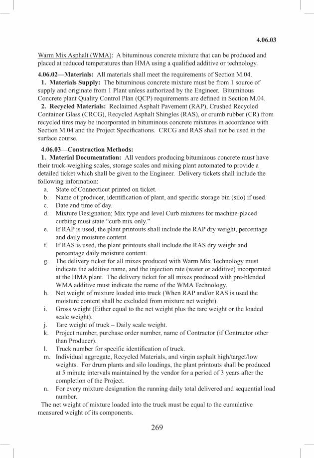
269
4.06.03
Warm Mix Asphalt (WMA): A bituminous concrete mixture that can be produced and placed at reduced temperatures than HMA using a qualified additive or technology.
4.06.02—Materials: All materials shall meet the requirements of Section M.04. 1. Materials Supply: The bituminous concrete mixture must be from 1 source of supply and originate from 1 Plant unless authorized by the Engineer. Bituminous Concrete plant Quality Control Plan (QCP) requirements are defined in Section M.04. 2. Recycled Materials: Reclaimed Asphalt Pavement (RAP), Crushed Recycled Container Glass (CRCG), Recycled Asphalt Shingles (RAS), or crumb rubber (CR) from recycled tires may be incorporated in bituminous concrete mixtures in accordance with Section M.04 and the Project Specifications. CRCG and RAS shall not be used in the surface course.
4.06.03—Construction Methods: 1. Material Documentation: All vendors producing bituminous concrete must have their truck-weighing scales, storage scales and mixing plant automated to provide a detailed ticket which shall be given to the Engineer. Delivery tickets shall include the following information:
a. State of Connecticut printed on ticket.b. Name of producer, identification of plant, and specific storage bin (silo) if used.c. Date and time of day.d. Mixture Designation; Mix type and level Curb mixtures for machine‑placed
curbing must state “curb mix only.”e. If RAP is used, the plant printouts shall include the RAP dry weight, percentage
and daily moisture content.f. If RAS is used, the plant printouts shall include the RAS dry weight and
percentage daily moisture content.g. The delivery ticket for all mixes produced with Warm Mix Technology must
indicate the additive name, and the injection rate (water or additive) incorporated at the HMA plant. The delivery ticket for all mixes produced with pre-blended WMA additive must indicate the name of the WMA Technology.
h. Net weight of mixture loaded into truck (When RAP and/or RAS is used the moisture content shall be excluded from mixture net weight).
i. Gross weight (Either equal to the net weight plus the tare weight or the loaded scale weight).
j. Tare weight of truck – Daily scale weight.k. Project number, purchase order number, name of Contractor (if Contractor other
than Producer).l. Truck number for specific identification of truck.m. Individual aggregate, Recycled Materials, and virgin asphalt high/target/low
weights. For drum plants and silo loadings, the plant printouts shall be produced at 5 minute intervals maintained by the vendor for a period of 3 years after the completion of the Project.
n. For every mixture designation the running daily total delivered and sequential load number.
The net weight of mixture loaded into the truck must be equal to the cumulative measured weight of its components.

270
4.06.03
The Contractor must notify the Engineer immediately if, during the production day, there is a malfunction of the weighing or recording system in the automated plant or truck-weighing scales. Manually written tickets containing all required information will be allowed for 1 hour, but for no longer, provided that each load is weighed on State-approved scales. At the Engineer’s sole discretion, trucks may be approved to leave the plant if a State inspector is present to monitor weighing. If such a malfunction is not fixed within 48 hours, mixture will not be approved to leave the plant until the system is fixed to the Engineer’s satisfaction. No damages will be considered should the State be unable to provide an inspector at the plant. The State reserves the right to have an inspector present to monitor batching and/or weighing operations. 2. Transportation of Mixture: Trucks with loads of bituminous concrete being delivered to State projects must not exceed the statutory or permitted load limits referred to as gross vehicle weight (GVW). The Contractor shall furnish a list of all vehicles and allowable weights transporting mixture. The State reserves the right to check the gross and tare weight of any delivery truck. A variation of 0.4% or less in the gross or tare weight shown on the delivery ticket and the certified scale weight shall be considered evidence that the weight shown on the delivery ticket is correct. If the gross or tare weight varies from that shown on the delivery ticket by more than 0.4%, the Engineer will recalculate the net weight. The Contractor shall take action to correct the discrepancy to the satisfaction of the Engineer. If a truck delivers mixture to the Project and the ticket indicates that the truck is overweight, the load will not be rejected but a “Measured Weight Adjustment” will be taken in accordance with Article 4.06.04. The mixture shall be transported from the mixing plant in trucks that have previously been cleaned of all foreign material and that have no gaps through which mixture might inadvertently escape. The Contractor shall take care in loading trucks uniformly so that segregation is minimized. Loaded trucks shall be tightly covered with waterproof covers acceptable to the Engineer. Mesh covers are prohibited. The front and rear of the cover must be fastened to minimize air infiltration. The Contractor shall assure that all trucks are in accordance with this specification. Non‑conforming trucks will not be allowed to be loaded until re-inspected and found satisfactory to the Engineer. Truck body coating and cleaning agents must not have a deleterious effect on the transported mixture. The use of solvents or fuel oil, in any concentration, is strictly prohibited for the coating of the inside of truck bodies. When acceptable coating or agents are applied, truck bodies shall be raised immediately prior to loading to remove any excess agent in an environmentally acceptable manner. 3. Paving Equipment: The Contractor shall have the necessary paving and compaction equipment at the Project Site to perform the work. All equipment shall be in good working order and any equipment that is worn, defective or inadequate for performance of the work shall be repaired or replaced by the Contractor to the satisfaction of the Engineer. During the paving operation, the use of solvents or fuel oil, in any concentration, is strictly prohibited as a release agent or cleaner on any paving equipment (i.e., rollers, pavers, transfer devices). Refueling of equipment is prohibited in any location on the paving Project where fuel might come in contact with bituminous concrete mixtures already placed or to be placed.

271
4.06.03
Solvents for use in cleaning mechanical equipment or hand tools shall be stored clear of areas paved or to be paved. Before any such equipment and tools are cleaned, they shall be moved off the paved or to be paved area; and they shall not be returned for use until after they have been allowed to dry. Pavers: Each paver shall have a receiving hopper with sufficient capacity to provide for a uniform spreading operation and a distribution system that places the mix uniformly, without segregation. The paver shall be equipped with and use a vibratory screed system with heaters or burners. The screed system shall be capable of producing a finished surface of the required evenness and texture without tearing, shoving, or gouging the mixture. Pavers with extendible screed units as part of the system shall have auger extensions and tunnel extenders as necessary. Automatic screed controls for grade and slope shall be used at all times unless otherwise authorized by the Engineer. The controls shall automatically adjust the screed to compensate for irregularities in the preceding course or existing base. The controls shall maintain the proper transverse slope and be readily adjustable, and shall operate from a fixed or moving reference such as a grade wire or floating beam. Rollers: All rollers shall be self-propelled and designed for compaction of bituminous concrete. Roller types shall include steel-wheeled, pneumatic or a combination thereof and may be capable of operating in a static or dynamic mode. Rollers that operate in a dynamic mode shall have drums that use a vibratory or oscillatory system or combination. The vibratory system achieves compaction through vertical amplitude forces. Rollers with this system shall be equipped with indicators that provide the operator with amplitude, frequency and speed settings/readouts to measure the number of impacts per foot during the compaction process. The oscillatory system achieves compaction through horizontal shear forces. Rollers with this system shall be equipped with frequency indicators. Rollers can operate in the dynamic mode using the oscillatory system on concrete structures such as bridges and catch basins if at the lowest frequency setting. Pneumatic tire rollers shall be self-propelled and equipped with wide-tread compaction tires capable of exerting an average contact pressure from 60 to 90 lb./in2 uniformly over the surface, adjusting ballast and tire inflation pressure as required. The Contractor shall furnish evidence regarding tire size, pressure and loading to confirm that the proper contact pressure is being developed and that the loading and contact pressure are uniform for all wheels. Lighting: For paving operations, which will be performed during hours of darkness, the paving equipment shall be equipped with lighting fixtures as described below, or with approved lighting fixtures of equivalent light output characteristics. Lighting shall maximize the illumination on each task and minimize glare to passing traffic. The Contractor shall provide generators on rollers and pavers of the type, size, and wattage, to adequately furnish electric power to operate the specified lighting equipment. The lighting options and minimum number of fixtures are listed in Tables 4.06‑1 and 4.06‑2:

272
4.06.03
TABLE 4.06-1: Paver Lighting
Option FixtureConfiguration Fixture Quantity Requirement
1
Type A 3 Mount over screed area
Type B (narrow) or Type C (spot) 2 Aim to auger and guideline
Type B (wide) or Type C (flood) 2 Aim 25 feet behind paving
machine
2 Type D Balloon 2 Mount over screed area
Type A: Fluorescent fixture shall be heavy duty industrial type. Each fixture shall have a minimum output of 8,000 lumens. The fixtures shall be mounted horizontally, and be designed for continuous row installation. Type B: Each floodlight fixture shall have a minimum output of 18,000 lumens. Type C: Each fixture shall have a minimum output of 19,000 lumens. Type D: Balloon light – each balloon light fixture shall have minimum output of
50,000 lumens and emit light equally in all directions.
TABLE 4.06-2: Roller Lighting
Option Fixture Configuration*
Fixture Quantity Requirement
1Type B (wide) 2 Aim 50 feet in front of and behind roller
Type B (narrow) 2 Aim 100 feet in front of and behind roller
2Type C (flood) 2 Aim 50 feet in front of and behind roller
Type C (spot) 2 Aim 100 feet in front of and behind roller
3 Type D Balloon 1 Mount above the roller *All fixtures shall be mounted above the roller. Type B: Each floodlight fixture shall have a minimum output of 18,000 lumens. Type C: Each fixture shall have a minimum output of 19,000 lumens. Type D: Balloon light – each balloon light fixture shall have minimum output of
50,000 lumens and emit light equally in all directions.
Material Transfer Vehicle (MTV): A MTV shall be used when placing a bituminous concrete surface course as indicated in the Contract. A surface course is defined as the total thickness of the same bituminous concrete mix that extends up to and includes the final wearing surface whether it is placed in a single or multiple lifts, and regardless of any time delays between lifts.
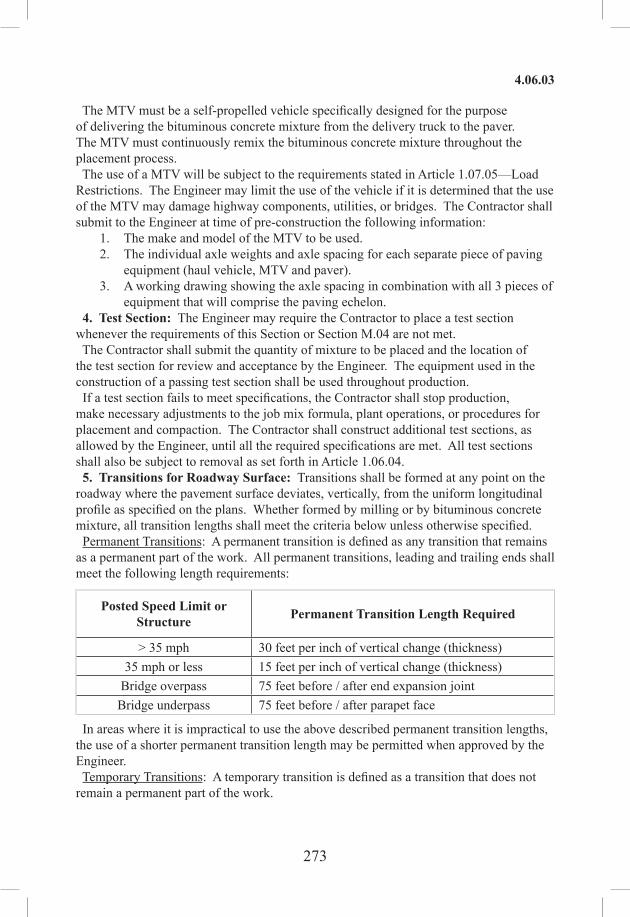
273
4.06.03
The MTV must be a self‑propelled vehicle specifically designed for the purpose of delivering the bituminous concrete mixture from the delivery truck to the paver. The MTV must continuously remix the bituminous concrete mixture throughout the placement process. The use of a MTV will be subject to the requirements stated in Article 1.07.05—Load Restrictions. The Engineer may limit the use of the vehicle if it is determined that the use of the MTV may damage highway components, utilities, or bridges. The Contractor shall submit to the Engineer at time of pre-construction the following information:
1. The make and model of the MTV to be used.2. The individual axle weights and axle spacing for each separate piece of paving
equipment (haul vehicle, MTV and paver).3. A working drawing showing the axle spacing in combination with all 3 pieces of
equipment that will comprise the paving echelon. 4. Test Section: The Engineer may require the Contractor to place a test section whenever the requirements of this Section or Section M.04 are not met. The Contractor shall submit the quantity of mixture to be placed and the location of the test section for review and acceptance by the Engineer. The equipment used in the construction of a passing test section shall be used throughout production. If a test section fails to meet specifications, the Contractor shall stop production, make necessary adjustments to the job mix formula, plant operations, or procedures for placement and compaction. The Contractor shall construct additional test sections, as allowed by the Engineer, until all the required specifications are met. All test sections shall also be subject to removal as set forth in Article 1.06.04. 5. Transitions for Roadway Surface: Transitions shall be formed at any point on the roadway where the pavement surface deviates, vertically, from the uniform longitudinal profile as specified on the plans. Whether formed by milling or by bituminous concrete mixture, all transition lengths shall meet the criteria below unless otherwise specified. Permanent Transitions: A permanent transition is defined as any transition that remains as a permanent part of the work. All permanent transitions, leading and trailing ends shall meet the following length requirements:
Posted Speed Limit or Structure Permanent Transition Length Required
> 35 mph 30 feet per inch of vertical change (thickness)35 mph or less 15 feet per inch of vertical change (thickness)
Bridge overpass 75 feet before / after end expansion jointBridge underpass 75 feet before / after parapet face
In areas where it is impractical to use the above described permanent transition lengths, the use of a shorter permanent transition length may be permitted when approved by the Engineer. Temporary Transitions: A temporary transition is defined as a transition that does not remain a permanent part of the work.

274
4.06.03
All temporary transitions shall meet the following length requirements:
Posted Speed Limit Temporary Transition Length Required
> 50 mph Leading Transition: 15 feet per inch of vertical change (thickness)Trailing Transition: 6 feet per inch of vertical change (thickness)
40, 45 or 50 mph Leading and Trailing: 4 feet per inch of vertical change (thickness)
35 mph or less Leading and Trailing: 3 feet per inch of vertical change (thickness)
Note: Any temporary transition to be in place over the winter shutdown period or during extended periods of inactivity (more than 14 calendar days) shall meet the greater than 50 MPH requirements shown above. 6. Spreading and Finishing of Mixture: Prior to the placement of the bituminous concrete, the underlying base course shall be brought to the plan grade and cross section within the allowable tolerance. Immediately before placing the mixture, the area to be surfaced shall be cleaned by sweeping or by other means acceptable to the Engineer. The bituminous concrete mixture shall not be placed whenever the surface is wet or frozen. The Engineer will verify the mix temperature by means of a probe or infrared type of thermometer. A probe type thermometer, verified by the Department on an annual basis, must be used in order to reject a load of mixture based on temperatures outside the range stated in the placement QCP. Placement: The bituminous concrete mixture shall be placed and compacted to provide a smooth, dense surface with a uniform texture and no segregation at the specified thickness and dimensions indicated in the plans and specifications. When unforeseen weather conditions prevent further placement of the mix, the Engineer is not obligated to accept or place the bituminous concrete mixture that is in transit from the plant. In advance of paving, traffic control requirements shall be set up daily, maintained throughout placement, and shall not be removed until all associated work including density testing is completed. The Contractor shall inspect the newly placed pavement for defects in the mixture or placement before rolling is started. Any deviation from standard crown or section shall be immediately remedied by placing additional mixture or removing surplus mixture. Such defects shall be corrected to the satisfaction of the Engineer. Where it is impractical due to physical limitations to operate the paving equipment, the Engineer may permit the use of other methods or equipment. Where hand spreading is permitted, the mixture shall be placed by means of suitable shovels and other tools, and in a uniformly loose layer at a thickness that will result in a completed pavement meeting the designed grade and elevation. Placement Tolerances: Each lift of bituminous concrete placed at a uniform specified thickness shall meet the following requirements for thickness and area. Any pavement exceeding these limits shall be subject to an adjustment or removal. Lift tolerances will not relieve the Contractor from meeting the final designed grade. Lifts of specified non‑

275
4.06.03
uniform thickness, i.e. wedge or shim course, shall not be subject to thickness and area adjustments.
a) Thickness: Where the total thickness of the lift of mixture exceeds that shown on the plans beyond the tolerances shown in Table 4.06-3, the longitudinal limits of such variation including locations and intervals of the measurements will be documented by the Engineer for use in calculating an adjustment in accordance with Article 4.06.04.
TABLE 4.06-3: Thickness TolerancesMixture Designation Lift Tolerance
S1 +/- 3/8 inchS0.25, S0.375, S0.5 +/- 1/4 inch
Where the thickness of the lift of mixture is less than that shown on the plans beyond the tolerances shown in Table 4.06-3, the Contractor, with the approval of the Engineer, shall take corrective action in accordance with this Section.
b) Area: Where the width of the lift exceeds that shown on the plans by more than the specified thickness of each lift, the longitudinal limits of such variation including locations and intervals of the measurements will be documented by the Engineer for use in calculating the adjustment in Article 4.06.04.
c) Delivered Weight of Mixture: When the delivery ticket shows that the truck exceeds the allowable gross weight for the vehicle type the quantity of tons representing the overweight amount will be documented by the Engineer for use in calculating an adjustment in accordance with Article 4.06.04.
Transverse Joints: All transverse joints shall be formed by saw‑cutting a sufficient distance back from the previous run, existing bituminous concrete pavement or bituminous concrete driveways to expose the full thickness of the lift. A brush of tack coat shall be used on any cold joint immediately prior to additional bituminous concrete mixture being placed. Tack Coat Application: Immediately before application, the area to be tacked shall be cleaned by sweeping or by other means acceptable to the Engineer. A thin uniform coating of tack coat shall be applied to the pavement immediately before overlaying and be allowed sufficient time to break (set) prior to any paving equipment or haul vehicles driving on it. All surfaces in contact with the bituminous concrete that have been in place longer than 3 calendar days shall have an application of tack coat. The tack coat shall be applied by a non-gravity pressurized spray system that results in uniform overlapping coverage at an application rate of 0.03 to 0.05 gal/s.y. for a non-milled surface and an application rate of 0.05 to 0.07 gal/s.y. for a milled surface. For areas where both milled and un-milled surfaces occur, the tack coat shall be an application rate of 0.03 to 0.05 gal/s.y. The Engineer must approve the equipment and the method of measurement prior to use. The material for tack coat shall not be heated in excess of 160°F and shall not be further diluted. Compaction: The Contractor shall compact the mixture to meet the density requirements as stated in Article 4.06.03 and eliminate all roller marks without displacement, shoving, cracking, or aggregate breakage. When placing a lift with a specified thickness less than 1 1/2 in, or a wedge course, the

276
4.06.03
Contractor shall provide a minimum rolling pattern as determined by the development of a compaction curve. The procedure to be used shall be documented in the Contractor’s QCP for placement and demonstrated on the first day of placement. The use of the vibratory system on concrete structures is prohibited. When approved by the Engineer, the Contractor may operate a roller using an oscillatory system at the lowest frequency setting. If the Engineer determines that the use of compaction equipment in the dynamic mode may damage highway components, utilities, or adjacent property, the Contractor shall provide alternate compaction equipment. The Engineer may allow the Contractor to operate rollers in the dynamic mode using the oscillatory system at the lowest frequency setting. Rollers operating in the dynamic mode shall be shut off when changing directions. These allowances will not relieve the Contractor from meeting pavement compaction requirements. Surface Requirements: The pavement surface of any lift shall meet the following requirements for smoothness and uniformity. Any irregularity of the surface exceeding these requirements shall be corrected by the Contractor.
a) Smoothness: Each lift of the surface course shall not vary more than 1/4 in from a Contractor-supplied 10 ft straightedge. For all other lifts of bituminous concrete, the tolerance shall be 3/8 in. Such tolerance will apply to all paved areas.
b) Uniformity: The paved surface of the mat and joints shall not exhibit segregation, rutting, cracking, disintegration, flushing or vary in composition as determined by the Engineer.
7. Longitudinal Joint Construction Methods: The Contractor shall use Method I- Notched Wedge Joint (see Figure 4.06-1) when constructing longitudinal joints where lift thicknesses are between 1 1/2 and 3 in, except for S1 mixes. Method II Butt Joint (see Figure 4.06-2) shall be used for lifts less than 1 1/2 in or greater than 3 in, and S1 mixes. During placement of multiple lifts of bituminous concrete, the longitudinal joint shall be constructed in such a manner that it is located at least 6 in from the joint in the lift immediately below. The joint in the final lift shall be at the centerline or at lane lines. Each longitudinal joint shall maintain a consistent offset from the centerline of the roadway along its entire length. The difference in elevation between the two faces of any completed longitudinal joint shall not exceed 1/4 in at any location. Method I - Notched Wedge Joint: A notched wedge joint shall be constructed as shown in Figure 4.06-1 using a device that is attached to the paver screed and is capable of independently adjusting the top and bottom vertical notches. The device shall have an integrated vibratory system. The taper portion of the wedge joint must be placed over the longitudinal joint in the lift immediately below. The top vertical notice must be located at the centerline or lane line in the final lift. The requirement for paving full width “curb to curb” as described in Method II may be waived if addressed in the QCP and approved by the Engineer. The taper portion of the wedge joint shall be evenly compacted using equipment other than the paver or notch wedge joint device. The taper portion of the wedge joint shall not be exposed to traffic for more than 5 calendar days. The pavement surface under the wedge joint must have an application of tack coat

277
4.06.03
material. Prior to placing the completing pass (hot side), an application of tack coat must be applied to the exposed surface of the tapered section; regardless of time elapsed between paver passes. The in-place time allowance described in Subarticle 4.06.03-7 does not apply to joint construction.
Any exposed wedge joint must be located to allow for the free draining of water from the road surface. The Engineer reserves the right to define the paving limits when using a wedge joint that will be exposed to traffic. If Method I, Notched Wedge Joint cannot be used on lifts between 1.5 and 3 in, Method III Butt Joint may be substituted according to the requirements below for “Method III – Butt Joint with Hot Pour Rubberized Asphalt Treatment.” Method II - Butt Joint: When adjoining passes are placed, the Contractor shall utilize equipmentthat creates a near vertical edge (refer to Figure 4.06-2).
FIGURE 4.06-2: Butt Joint (Not to Scale)
The completing pass (hot side) shall have sufficient mixture so that the compacted thickness is not less than the previous pass (cold side). The end gate on the paver should be set so there is an overlap onto the cold side of the joint. The Contractor shall not allow any butt joint to be incomplete at the end of a work shift unless otherwise allowed by the Engineer. When using this method, the Contractor is not allowed to leave a vertical edge exposed at the end of a work shift and must complete paving of the roadway full width “curb to curb.”
MazeauJL
Typewritten Text
MazeauJL
Typewritten Text
MazeauJL
Typewritten Text
MazeauJL
Typewritten Text
MazeauJL
Typewritten Text
0 -

278
4.06.03
Method III - Butt Joint with Hot Poured Rubberized Asphalt Treatment: If Method I Notched Wedge Joint cannot be used due to physical constraints in certain limited locations; the Contractor may submit a request in writing, for approval by the Engineer, to utilize Method III Butt Joint with Hot Poured Rubberized Asphalt Treatment as a substitution in those locations. There shall be no additional measurement or payment made when the Method III joint is substituted for the Method I wedge joint. When required by the Contract or approved by the Engineer, Method III (see Figure 4.06-3) shall be used.
FIGURE 4.06-3: Butt Joint with Hot Poured Rubberized Asphalt Treatment(Not to Scale)
All of the requirements of Method II must be met with Method III. In addition, the longitudinal vertical edge must be treated with a rubberized joint seal material meeting the requirements of ASTM D6690, Type 2. The joint sealant shall be placed on the face of the “cold side” of the butt joint as shown above prior to placing the “hot side” of the butt joint. The joint seal material shall be applied in accordance with the manufacturer’s recommendation so as to provide uniform coverage and avoid excess bleeding onto the newly placed pavement. 8. Contractor Quality Control (QC) Requirements: The Contractor shall be responsible for maintaining adequate quality control procedures throughout the production and placement operations. Therefore, the Contractor must ensure that the materials, mixture and work provided by subcontractors, suppliers and producers also meets Contract specification requirements. This effort must be documented in a Quality Control Plan (QCP) which shall also address the actions, inspection, or sampling and testing necessary to keep the production and placement operations in control, to determine when an operation has gone out of control and to respond to correct the situation in a timely fashion. The Standard QCP for production shall consist of the quality control program specific to the production facility. There are 3 components to the QCP for placement: a Standard QCP, a Project Summary Sheet that details Project‑specific information, and if applicable a separate Extended Season Paving Plan as required in Section 9 “Temperature and Seasonal Requirements.” The Standard QCP for both production and placement shall be submitted to the Department for approval each calendar year, a minimum of 30 days prior to production or placement. Production or placement shall not occur until all QCP components have been

279
4.06.03
approved by the Engineer. Each QCP shall include the name and qualifications of a Quality Control Manager (QCM). The QCM shall be responsible for the administration of the QCP, and any modifications that may become necessary. The QCM shall have the ability to direct all Contractor personnel on the Project during paving operations. All Contractor sampling, inspection and test reports shall be reviewed and signed by the QCM prior to submittal to the Engineer. The QCP shall also include the name and qualifications of any outside testing laboratory performing any QC functions on behalf of the Contractor. Approval of the QCP does not relieve the Contractor of its responsibility to comply with the Project specifications. The Contractor may modify the QCP as work progresses and must document the changes in writing prior to resuming operations. These changes include but are not limited to changes in quality control procedures or personnel. The Department reserves the right to deny significant changes to the QCP. QCP for Production: Refer to M.04.03-1. QCP for Placement: The Standard QCP, Project Summary Sheet, and Extended Season Paving Plan shall be in the format provided by the Engineer. The format is available at http://www.ct.gov/dot/lib/dot/documents/dconstruction/pat/qcp_outline_hma_placement.pdf. The Contractor shall perform all quality control sampling and testing, provide inspection, and exercise management control to ensure that bituminous concrete placement meets the requirements as outlined in its QCP during all phases of the work. The Contractor shall document these activities for each day of placement. The Contractor shall submit complete field density testing and inspection records to the Engineer within 48 hours of the test in a manner acceptable to the Engineer. The Contractor may obtain 1 mat core and 1 joint core per day for process control, provided this process is detailed in the QCP. The results of these process control cores shall not be used to dispute the Department determinations from the acceptance cores. The Contractor shall submit the location of each process control core to the Engineer for approval prior to taking the core. The core holes shall be filled to the same requirements described in Subarticle 4.06.03-10. 9. Temperature and Seasonal Requirements: Paving, including placement of temporary pavements, shall be divided into 2 seasons, “In-Season” and “Extended-Season.” In-Season paving occurs from May 1 to October 14, and Extended Season paving occurs from October 15 to April 30. The following requirements shall apply unless otherwise authorized or directed by the Engineer:• Bituminous concrete mixes shall not be placed when the air or subbase temperature is below 40°F regardless of the season.• Should paving operations be scheduled during the Extended Season, the Contractor must submit an Extended Season Paving Plan for the Project that addresses minimum delivered mix temperature considering WMA, PMA or other additives, maximum paver speed, enhanced rolling patterns and the method to balance mixture delivery and placement operations. Paving during Extended Season shall not commence until the Engineer has approved the plan. 10. Density Testing of Bituminous Concrete Using Core Samples: This procedure describes the frequency and the method the Contractor shall use to obtain pavement cores for acceptance from the Project.

280
4.06.03
Coring shall be performed on each lift specified to a thickness of 1 1/2 in or more. All material placed in a lift shall be compacted to the degree specified in Tables 4.06‑8 and 4.06-9. The density of each core will be determined using the production lot’s average maximum theoretical specific gravity (Gmm) established during the testing of the parent material at the plant. When there was no testing of the parent material or any Gmm exceeds the specified tolerances in the Department’s current QA Program for Materials, the Engineer will determine the maximum theoretical density value to be used for density calculations. Bituminous concrete HMA S1 mixes are excluded from the longitudinal joint density requirements. The Contractor shall extract cores (4 or 6 in diameter for S0.25, S0.375 and S0.5 mixes, 6 in diameter for S1.0 mixtures - wet sawed) from sampling locations determined by the Engineer. The Engineer must witness the extraction and labeling of cores, as well as the filling of the core holes. The cores shall be labeled by the Contractor with the Project number, lot number, and sub-lot number on the top surface of the core. When labeling the core lot number, include whether the core is from a mat lot or joint lot by using an “M” for a mat core and “J” for a joint core. For example, a core from the first sub‑lot of the first mat lot shall be labeled with “Lot M1 – 1.” The first number refers to the lot and the second number refers to the sub-lot. See Figure 4.06-4. The side of the cores shall be labeled with the core lot number and date placed. The Project inspector will fill out a MAT-109 containing the same information to accompany the cores. The Contractor shall deliver the cores and MAT-109 to the Department’s Central Testing Lab in a safe manner to ensure no damage occurs to the cores. The Contractor shall use a container approved by the Engineer. In general the container shall consist of an attached lid container made out of plastic capable of being locked shut and shall be tamper proof. The Contractor shall use foam, bubble wrap, or another suitable material to prevent the cores from being damaged during transportation. Once the cores and MAT-109 are in the container, the Engineer will secure the lid using a security seal. The security seal’s identification number must be documented on the MAT-109. The Central Lab will break the security seal and take possession of the cores upon receipt.
FIGURE 4.06-4: Labeling of Cores

281
4.06.03
Frequency of sampling shall be in accordance with the following tables:
TABLE 4.06-4: Testing Requirement for Bridge Density LotLength of Each Structure (Feet)
MAT -No. of Cores
Joint -No. of Cores
≤ 500 See Table 4.06-5(A or B) See Table 4.06-5(A or B)501 - 1500 3 31501 - 2500 4 4
2501 and greater 5 5
All material placed on structures less than or equal to 500 ft long shall be included as part of a standard lot as follows:
TABLE4.06-5A:TestingRequirementforDensityLots≥500Tons
Lot Type No. of Mat Cores No. of Joint Cores Target LotSize (Tons)
Lot without Bridge(1) 4 4 2000
Lot with Bridge(s)(1)(2) 4 plus
1 perstructure(≤ 300’)
4 plus
1 perstructure(≤ 300’)
20002 per
structure(301’-500’)
2 perstructure
(301’-500’)
TABLE 4.06-5B: Testing Requirement for Density Lots < 500 TonsLot Type No. of Mat Cores No. of Joint Cores Target Lot
Size (Tons)Lot without
Bridge(1) 3 3 1 per lift
Lot with Bridge(s)(1)(2) 3 3 1 per lift
Notes for Tables 4.06-5A and 4.06-5B: (1) The number of “Required Paver Passes for Full Width” shall be used to determine the sub-lot sizes within the lot. The number of paver passes for full width is determined by the Contractor. (2) If a non-bridge mat or joint core location randomly falls on a structure, the core is to be obtained on the structure in addition to the core(s) required on the structure.
A density lot will be complete when the full designed paving width of the established lot length has been completed and shall include all longitudinal joints that exist between the curb lines regardless of date(s) paved. Quantity of material placed on structures less than or equal to 500 ft long is inclusive of the standard lot. Prior to paving, the total length of the Project to be paved shall be split up into lots that contain approximately 2000

282
4.06.03
tons each. Areas such as highway ramps may be combined to create one lot. In general, combined areas should be set up to target a 2000 ton lot size. One (1) adjustment will apply for each lot. The tons shall be determined using the yield calculation in Article 4.06.04. The last lot shall be the difference between the total payable tons for the Project and the sum of the previous lots. After the compaction process has been completed, the material shall be allowed to cool sufficiently to allow the cutting and removal of the core without damage. The Contractor shall core to a depth that allows extraction so that the uppermost layer being tested for density will not be affected. A mat core shall not be taken any closer than 1 ft from the edge of a paver pass. If a random number locates a core less than 1 ft from any edge, locate the core so that the sample is 1 ft from the edge. When Method I, Notched Wedge Joint cores shall be taken so that the center of the core is 5 in from the visible joint on the hot mat side. Refer to Figure 4.06-5. When Method III Butt Joint with Hot Poured Rubberized Asphalt Treatment is used, cores shall be taken from the hot side so the edge of the core is within 1 in of the longitudinal joint. All cores must be cut within 5 calendar days of placement. Any core that is damaged or obviously defective while being obtained will be replaced with a new core from a location within 2 ft measured in a longitudinal direction. Each core hole shall be filled within 4 hours upon core extraction. Prior to being filled, the hole shall be prepared by removing any free water and applying tack coat using a brush or other means to uniformly cover the cut surface. The core hole shall be filled using a bituminous concrete mixture at a minimum temperature of 240ºF containing the same or smaller nominal maximum aggregate size and compacted with a hand compactor or other mechanical means to the maximum compaction possible. The bituminous concrete fill shall be compacted to 1/8 in above the finished pavement.
FIGURE 4.06-5: Notched Wedge Joint Cores (Not to Scale)
11. Acceptance Inspection, Sampling and Testing: Inspection, sampling, and testing to be used by the Engineer shall be performed at the minimum frequency specified in Section M.04 and stated herein. Sampling for acceptance shall be established using ASTM D3665, or a statistically based procedure of random sampling approved by the Engineer. Plant Material Acceptance: The Contractor shall provide the required acceptance sampling, testing and inspection during all phases of the work in accordance with Section

283
4.06.03
M.04. The Department will perform verification testing on the Contractor’s acceptance test results. Should binder content, theoretical maximum density (Gmm), or air void results exceed the specified tolerances in the Department’s current QA Program for Materials, Acceptance and Assurance Testing Policies and Procedures, the Department will investigate to determine an assignable cause. Contractor test results for a subject lot or sub lot may be replaced with the Department’s results for the purpose of assessing adjustments. The verification procedure is included in the Department’s current QA Program for Materials. Density Acceptance: The Engineer will perform all acceptance testing on the cores in accordance with AASHTO T 331. 12. Density Dispute Resolution Process: The Contractor and Engineer will work in partnership to avoid potential conflicts and to resolve any differences that may arise during quality control or acceptance testing for density. Both parties shall review their sampling and testing procedures and results and share their findings. If the Contractor disputes the Engineer’s test results, the Contractor must submit a written request to initiate the Dispute Resolution Process within 7 calendar days of the notification of the test results. No request for dispute resolution will be allowed unless the Contractor provides quality control results within the timeframe described in Subarticle 4.06.03-9 supporting its position. No request for Dispute Resolution will be allowed for a Density Lot in which any core was not taken within the required 5 calendar days of placement. Should the dispute not be resolved through evaluation of existing testing data or procedures, the Engineer may authorize the Contractor to obtain a new set of core samples per disputed lot. The core samples must be extracted no later than 14 calendar days from the date of Engineer’s authorization. The number and type (mat, joint, or structure) of the cores taken for dispute resolution must reflect the number and type of the cores taken for acceptance. The location of each core shall be randomly located within the respective original sub lot. All such core samples shall be extracted and filled using the procedure outlined in Article 4.06.03. The results from the dispute resolution cores shall be added to the results from the acceptance cores and averaged for determining the final in‑place density value. 13. Corrective Work Procedures: Any portion of the completed pavement that does not meet the requirements of the specification shall be corrected at the expense of the Contractor. Any corrective courses placed as the final wearing surface shall match the specified lift thickness after compaction. If pavement placed by the Contractor does not meet the specifications, and the Engineer requires its replacement or correction, the Contractor shall: a) Propose a corrective procedure to the Engineer for review and approval prior to any corrective work commencing. The proposal shall include: • Limits of pavement to be replaced or corrected, indicating stationing or other criteria that are readily distinguishable. • Proposed work schedule. • Construction method and sequence of operations. • Methods of maintenance and protection of traffic. • Material sources. • Names and telephone numbers of supervising personnel. b) Perform all corrective work in accordance with the Contract and the approved

284
4.06.04
corrective procedure. 14. Protection of the Work: The Contractor shall protect all sections of the newly finished pavement from damage that may occur as a result of the Contractor’s operations for the duration of the Project. Prior to the Engineer’s authorization to open the pavement to traffic, the Contractor is responsible to protect the pavement from damage. 15. Cut Bituminous Concrete Pavement: Work under this item shall consist of making a straight-line cut in the bituminous concrete pavement to the lines delineated on the plans or as directed by the Engineer. The cut shall provide a straight, clean, vertical face with no cracking, tearing or breakage along the cut edge.
4.06.04—Method of Measurement: 1.HMAS*orPMAS*: The quantity of bituminous concrete measured for payment will be determined by the documented net weight in tons accepted by the Engineer in accordance with this Section and Section M.04. 2. Adjustments: Adjustments may be applied to bituminous concrete quantities and will be measured for payment using the following formulas:Yield Factor for Adjustment Calculation = 0.0575 Tons/SY/inch
Actual Area (SY) = [Measured Length (ft) x Avg. of width measurements (ft)]÷9 s.f./SY
Actual Thickness (t) = Total tons delivered / [Actual Area (SY) x 0.0575 Tons/SY/inch] a) Area: If the average width exceeds the allowable tolerance, an adjustment will be made using the following formula. The tolerance for width is equal to the specified thickness (inches) of the lift being placed.
Tons Adjusted for Area (TA) = [(L x Wadj)/9] x (t) x 0.0575 Tons/SY/inch = (-) Tons
Where: L = Length (ft) (t) = Actual thickness (inches) Wadj = (Designed width (ft) + tolerance /12) - Measured Width) b) Thickness: If the actual thickness is less than the allowable tolerance, the Contractor shall submit a repair procedure to the Engineer for approval. If the actual thickness exceeds the allowable tolerance, an adjustment will be made using the following formula:
Tons Adjusted for Thickness (TT) = A x tadj x 0.0575 = (-) Tons
Where: A = Area = {[L x (Design width + tolerance (lift thickness)/12)]÷9} tadj = Adjusted thickness = [(Design thickness + tolerance) - Actual thickness] (Note: Design thickness, tolerance and Actual thickness in inches) c) Weight: If the quantity of bituminous concrete representing the mixture delivered to the Project is in excess of the allowable gross vehicle weight (GVW) for each vehicle, an adjustment will be made using the following formula:
Tons Adjusted for Weight (TW) = GVW – DGW= (-) Tons
Where: DGW = Delivered gross weight as shown on the delivery ticket or measured on a certified scale. d) Mixture Adjustment: The quantity of bituminous concrete representing the production lot will be adjusted based on test results and values listed in Tables 4.06-6 and 4.06-7. The Department’s Division of Material Testing will calculate the daily

285
4.06.04
adjustment value for TSD. The adjustment values in Table 4.06-6 and 4.06-7 will be calculated for each sub lot based on the Air Void and Liquid Binder Content test results for that sub lot. The total adjustment for each day’s production (lot) will be computed using tables and the following formulas:
Tons Adjusted for Superpave Design (TSD) = [(AdjAVt + AdjPBt) / 100] x Tons
Percent Adjustment for Air Voids = AdjAVt = [AdjAV1 + AdjAV2 + AdjAVi + … + AdjAVn)] /n
Where: AdjAVt = Total percent air void adjustment value for the lot AdjAVi = Adjustment value from Table 4.06-7 resulting from each sub lot or the average of the adjustment values resulting from multiple tests within a sub lot, as approved by the Engineer. n = number of sub lots based on Table M.04.03-1
TABLE 4.06-6: Adjustment Values for Air VoidsAdjustment Value
(AdjAVi) (%)S0.25, S0.375, S0.5, S1
Air Voids (AV)+2.5 3.8 - 4.2
+3.125 x (AV-3) 3.0 - 3.7-3.125 x (AV-5) 4.3 -5.0
20 x (AV-3) 2.3 - 2.9-20 x (AV-5) 5.1 - 5.7
-20.0 less than or equal to 2.2 orgreater than or equal to 5.8
Positive air void adjustment values will not be calculated for any test that fails to meet gradation or binder content tolerances of the JMF in Table M.04.03-5.
Percent Adjustment for Liquid Binder = AdjPBt = [(AdjPB1 + AdjPB2 + AdjPBi + … + AdjPBn)] / n
Where: AdjPBt = Total percent liquid binder adjustment value for the lot AdjPBi = Adjustment value from Table 4.06-7 resulting from each sub lot n = number of binder tests in a production lot
TABLE 4.06-7: Adjustment Values for Binder Content Adjustment Value (AdjAVi)
(%)S0.25, S0.375, S0.5, S1
Pb (refer to Table M.04.02-5)0.0 Equal to or above the min. liquid content
-10.0 Below the min. liquid content
e) Density Adjustment: The quantity of bituminous concrete measured for payment in a lift of pavement specified to be 1 1/2 in or greater may be adjusted for density. Separate density adjustments will be made for each lot and will not be combined to establish 1

286
4.06.04
density adjustment. If either the Mat or Joint adjustment value is “remove and replace,” the density lot shall be removed and replaced (curb to curb). No positive adjustment will be applied to a Density Lot in which any core was not taken within the required 5 calendar days of placement.Tons Adjusted for Density (TD) = [{(PAM x 0.50) + (PAJ x 0.50)} / 100] x Density Lot Tons
Where: TD = Total tons adjusted for density for each lot PAM = Mat density percent adjustment from Table 4.06-8 PAJ = Joint density percent adjustment from Table 4.06-9
TABLE 4.06-8: Adjustment Values for Pavement Mat densityAverage Core Result
Per Mat DensityPercent Adjustment
(Bridge and Non-Bridge)(1)(2)
97.1 - 100 -1.667 x (ACRPD-98.5)94.5 - 97.0 +2.593.5 - 94.4 +2.5 x (ACRPD-93.5)92.0 - 93.4 090.0 - 91.9 -5 x (92-ACRPD)88.0 - 89.9 -10 x (91-ACRPD)87.0 - 87.9 -3086.9 or less Remove and Replace (curb to curb)
Notes: (1) ACRPD = Average Core Result Percent Density (2) All Percent Adjustments to be rounded to the second decimal place. For example, 1.667 is to be rounded to 1.67.
TABLE 4.06-9: Adjustment Values for Pavement Joint DensityAverage Core
ResultPercent Joint
Density
Percent Adjustment(Bridge and Non-Bridge)(1)(2)
97.1 - 100 -1.667 x (ACRPD-98.5)93.5 - 97.0 +2.592.0 - 93.4 +1.667 x (ACRPD-92)91.0 - 91.9 089.0 - 90.9 -7.5 x (91-ACRPD)88.0 - 88.9 -15 x (90-ACRPD)87.0 - 87.9 -3086.9 or less Remove and Replace (curb to curb)
Notes (for Table 4.06-9): (1) ACRPD = Average Core Result Percent Density (2) All Percent Adjustments to be rounded to the second decimal place. For example,

287
4.06.05
1.667 is to be rounded to 1.67.
3. Transitions for Roadway Surface: The installation of permanent transitions will be measured under the appropriate HMA or PMA item used in the formation of the transition. The quantity of material used for the installation of temporary transitions will be measured for payment under the appropriate item used in the formation of the transition. The installation and removal of a bond breaker, and the removal and disposal of any temporary transition formed by milling or with bituminous concrete pavement will not be measured for payment. 4. Cut Bituminous Concrete Pavement: The quantity of bituminous concrete pavement cut will be measured in accordance with Article 2.02.04. 5. Material for Tack Coat: The quantity of tack coat will be measured for payment by the number of gallons furnished and applied on the Project and approved by the Engineer. No tack coat material shall be included that is placed in excess of the application rates described in Subarticle 4.06.03-6. a. Container Method - Material furnished in a container will be measured to the nearest 1/2 gallon. The volume will be determined by either measuring the volume in the original container by a method approved by the Engineer or using a separate graduated container capable of measuring the volume to the nearest 1/2 gallon. The container in which the material is furnished must include the description of material, including lot number or batch number and manufacturer or product source. b. Truck Method - The Engineer will establish a weight per gallon of the tack coat based on the density at 60ºF for the material furnished. The number of gallons furnished will be determined by weighing the material on scales furnished by and at the expense of the Contractor, or from the automated metering system on the delivery vehicle. 6. Material Transfer Vehicle (MTV): The furnishing and use of a MTV will be measured separately for payment based on the actual number of surface course tons delivered to a paver using the MTV.
4.06.05—Basis of Payment: 1.HMAS*orPMAS*: The furnishing and placing of bituminous concrete will be paid for at the Contract unit price per ton for “HMA S*” or “PMA S*”. All costs associated with providing illumination of the work area are included in the general cost of the work. All costs associated with cleaning the surface to be paved, including mechanical sweeping, are included in the general cost of the work. All costs associated with constructing longitudinal joints are included in the general cost of the work. All costs associated with obtaining cores for acceptance testing and dispute resolution are included in the general cost of the work. 2. Bituminous Concrete Adjustment Costs: This adjustment will be calculated using the formulas shown below if all of the measured adjustments in Article 4.06.04 are not equal to zero. A positive or negative adjustment will be applied to monies due the Contractor.
Production Lot: [TT + TA + TW + TSD] x Unit Price = Est. (P)

288
4.06.05
Density Lot: TD x Unit Price = Est. (D)
Where: Unit Price = Contract unit price per ton per type of mixture TT = Total tons adjusted for thickness (see Article 4.06.04) TA = Total tons adjusted for area TW = Total tons adjusted for weight TSD = Total tons adjusted for Superpave design TD = Total tons adjusted for density Est. ( ) = Pay Unit in dollars representing incentive or disincentive The Bituminous Concrete Adjustment Cost item, if included in the bid proposal or estimate, is not to be altered in any manner by the Bidder. If the Bidder should alter the amount shown, the altered figure will be disregarded and the original estimated cost will be used for the Contract. 3. Transitions for Roadway Surface: The installation of permanent transitions will be paid under the appropriate HMA or PMA item used in the formation of the transition. The quantity of material used for the installation of temporary trnsitions will be paid under the appropriate pay item used in the formation of the transition. The installation and removal of a bond breaker, and the removal and disposal of any temporary transition formed by milling or with bituminous concrete pavement is included in the general cost of the work. 4. The cutting of bituminous concrete pavement will be paid in accordance with Article 2.02.05 for “Cut Bituminous Concrete Pavement.” 5. Material for tack coat will be paid for at the Contract unit price per gallon for “Material for Tack Coat.” 6. The Material Transfer Vehicle (MTV) will be paid at the Contract unit price per ton for “Material Transfer Vehicle.” Pay Item Pay Unit HMA S* ton PMA S* ton Bituminous Concrete Adjustment Cost est. Material for Tack Coat gal. Material Transfer Vehicle ton

289
4.15.05
SECTION 4.15PRESSURE RELIEF JOINT
4.15.01—Description: Work under this item shall consist of constructing, in the new or existing reinforced concrete pavement, a pressure relief joint composed of a bituminous concrete pavement course on a bituminous concrete base course. The pressure relief joint shall be constructed on the prepared subbase in accordance with these specifications and in accordance with the lines, grades, compacted thickness, pavement class, and cross-sections shown on the plans.
4.15.02—Materials: Materials shall meet the requirements of Section M.04.
4.15.03—Construction Methods: Construction methods of pressure relief joints shall meet the applicable requirements of Section 4.06, 2.02, and 2.12. Prior to the installation of the pressure relief joint, the subbase shall be adjusted to the correct grade, with additional material, if required, and compacted. 4.15.04—Method of Measurement: This work will be measured by the actual number of square yards of completed and accepted pressure relief joint.
4.15.05—Basis of Payment: This work will be paid for at the Contract unit price per square yard for “Pressure Relief Joint,” completed and accepted in place, which price shall include all materials, equipment, tools and labor and work incidental thereto. There will be no payment for cutting concrete pavement and bituminous concrete pavement, removal of concrete pavement and bituminous concrete pavement, additional subbase, and compaction of subbase, but the cost thereof shall be considered in the general cost of the pressure relief joint.
Pay Item Pay UnitPressure Relief Joint s.y.

290
5.01.01
STRUCTURES
SECTION 5.01GENERAL CLAUSES
5.01.01—Preservation of Channel5.01.02—Navigable Streams and Harbors5.01.03—Railroad Crossings
5.01.01—Preservation of Channel: Unless otherwise specified, no excavation shall be made outside of cofferdams; and the natural bed adjacent to the structure shall not be disturbed without permission from the Engineer. If the Contractor does any excavating or dredging at the site of the structure before cofferdams or similar construction are in place, the Contractor shall, without extra charge, after the foundations are in place, backfill all such excavated areas to the level of the original ground surface or stream bed with material satisfactory to Engineer. Material deposited within the stream area from foundation or other excavation or from the filling of cofferdams, and all temporary construction resulting from the Contractor’s operations shall be removed so as to leave the whole in a neat and presentable condition satisfactory to the Engineer. Structures or any portions thereof, which are founded on bedrock, shall not be constructed until all required rock excavation within a minimum distance of 100 ft is completed to the slope lines and depths indicated on the plans. The Contractor shall carry out the construction operations in accordance with all Federal, State or local requirements relative to the locations and dimensions of channel openings. The Contractor shall not obstruct such channels as are required for navigation purposes or the free flow of the stream at any time, except to such extent as the Engineer and other authority may permit, and shall be responsible for all damage, both to the work and to the property of others, resulting from any temporary obstruction placed in the channel or stream bed.
5.01.02—Navigable Streams and Harbors: When performing construction work in, over or immediately adjacent to navigable waters, the work shall be carried out subject to the requirements of DEEP and the U.S. Army Corps of Engineers, relative to channel clearance and depth, obstructions, etc., and the work shall be lighted and protected as may be required by the U.S. Coast Guard or other Federal agency having jurisdiction. No excavated material shall be deposited in navigable waters or adjacent thereto except as permitted by the U.S. Army Corps of Engineers.
5.01.03—Railroad Crossings: When the Contract includes work to be done on, over, under or immediately adjacent to the right of way of any railroad company, the work shall be subject to inspection by representatives of the railroad company, insofar as its interests are concerned, and all operations affecting railroad property or the operation of trains shall be carried out in accordance with the railroad’s requirements. The Contractor shall comply with all instructions given relative to the preservation of property, the operation of trains and the safety of all concerned. The railroad company will provide flagmen for the protection of railroad traffic and those engaged in the work during periods when the nature of the Contractor’s operations is such as to make it necessary. The character and extent of the flag protection necessary shall be determined and agreed upon by the railroad company and the Engineer.

291
5.03.01
Payment for any special or unusual work required to be done by the Contractor shall be described in the special provisions. The Contractor shall carry insurance in accordance with the requirements of Article 1.03.07. The amount of coverage required may vary, depending upon the location and character of the Project, and shall be as stated in the special provisions. The limits of liability with respect to insurance in favor of the Contractor and that in favor of the railroad will be as stated in the special provisions. Contractor’s public liability and property damage insurance shall furnish protection to the Contractor only in respect to their operations, or those of subcontractors, in performing the work covered by the Contract. However, when railroad employees are assigned or loaned to the Contractor to perform work in connection with their operations which are not in any way connected with the movement of trains of the railroad, or is not done under the direct control of the railroad, and if such employees are subject to the direction and control of the Contractor in all matters pertaining to their work and are employees of the Contractor, as evidenced by Project payrolls, the insurance coverage shall include such railroad employees so assigned or loaned to the Contractor. Railroads’ protective public liability and property damage insurance shall furnish protection to the railroad only in respect to the direct operation of the Contractor and subcontractors in performing the work covered by the Contract, including acts and omissions of all regular employees of the Contractor and subcontractors in connection with the work. The policy will definitely exclude coverage from liability imposed upon railroads by law due to their negligence or the negligence of their agents or employees in connection with all their direct operations, including railroad operations, any construction or other work that may be performed by them in connection with the Project, and also in connection with the acts and omissions of all railroad employees assigned to the work covered by the Contract. However, when railroad employees are assigned or loaned to the Contractor to perform work in connection with their operations, which is not in any way connected with the movement of trains of the railroad, or is not done under the direct control of the railroad, and if such employees are subject to the direction and control of the Contractor in all matters pertaining to their work and are employees of the Contractor, as evidenced by Project payrolls, then such railroad employees so assigned or loaned to the Contractor shall not be deemed to be employees of the railroad under the policy; but in no event will the policy afford coverage for the railroad in respect to injuries to such railroad employees themselves not arising from the negligence of the Contractor or his employees.
SECTION 5.03REMOVAL OF AND ALTERATIONS TO
EXISTING BRIDGES5.03.01—Description5.03.02—Materials5.03.03—Construction Methods5.03.04—Method of Measurement5.03.05—Basis of Payment
5.03.01—Description: This work shall include the removal and satisfactory disposal of all bridges or parts of bridges, including superstructure, substructure and approaches,

292
5.03.02
the removal of which is necessary to the final completion of the work. When stated in the special provisions or on the plans, the bridge may be required to be removed before permanent construction is started; or it may be required to be kept open for the use of traffic during the construction of the new work and to be removed after its final completion. It shall also include alterations or additions to or strengthening of existing bridges which are not to be removed when such work is included in the requirement of the plans and special provisions. All work shall be done in accordance with the requirements of the plans or as ordered and in accordance with these specifications.
5.03.02—Materials: The materials required for this work shall be as shown on the plans or as ordered. All materials shall meet the requirements of these specifications or the special provisions for the material in question; or if not so specified, they shall be of a quality satisfactory to the Engineer.
5.03.03—Construction Methods: Existing bridges which are to be removed by the Contractor shall be taken down and disposed of by such methods as the Contractor may propose, subject to the approval of the Engineer. Care shall be taken that the removal does not result in injury to any permanent construction or to adjoining property. Any material designated to remain the property of the Department shall be carefully removed and stored at a point adjacent to the Site to be designated by the Engineer. When so required by the Engineer, the several parts shall be match-marked as directed to facilitate re-erection. Any suitable concrete, masonry or similar material removed shall be placed in approach embankments or used for slope or foundation protection if the Engineer so directs. All material not designated for definite use shall be disposed of by the Contractor. When an existing structure is to be used by traffic during the construction of the new work, the Contractor shall relocate and strengthen it, if so required by the plans and special provisions. Temporary approaches shall be built if required, and the structure and approaches shall be repaired and renewed as necessary to keep them in a safe and satisfactory condition for the use of traffic at all times until the new structure is completed and open to traffic. The Contractor shall prepare and submit to the Engineer for approval plans for falsework or for changes in an existing structure necessary for maintaining traffic. Approval of the Contractor’s plans shall not be considered as relieving the Contractor of any responsibility. All such plans prepared by the Contractor shall be considered working drawings and shall be submitted with engineering calculations to the Engineer for review in accordance with the requirements of Article 1.05.02. The Contractor shall take all precautions and do such work as may be necessary to prevent damage to the structure or approaches due to the construction operations. When no longer required for traffic, the structure(s) shall be removed, as specified above, and the approaches graded in accordance with the requirements of the plans or as ordered. All existing piers, abutments or other portions of structures that constitute obstructions to stream channels shall be removed to the bed of the stream, unless otherwise specified on the plans. Any portions of existing structures not within a stream channel, shall be removed to a depth of 1 ft below the surface of the surrounding ground unless otherwise shown on the plans or directed by the Engineer.

293
5.03.05
When an existing structure is to be altered, added to or strengthened as part of the permanent construction, the work shall be done in accordance with the plans, special provisions and these specifications for the kind of material or work involved. In widening or altering an existing concrete structure, concrete shall not be removed by methods that are likely to cause damage to the concrete or reinforcement that are to remain in place in the completed structure. All reinforcement intended to be reused shall be cleaned and straightened or bent to the required dimensions.
5.03.04—Method of Measurement: Measurements necessary to determine the quantities for payment under any of the requirements specified above shall be made in accordance with the requirements of these specifications for the items involved unless otherwise stated on the plans or in the special provisions.
5.03.05—Basis of Payment: Payment for the above-described work shall be made as follows: When a superstructure is to be removed, whether the total structure is to be removed or only the superstructure, the work will be paid for at the Contract lump sum price for “Removal of Superstructure,” at the location designated, complete, including disposal of material and all materials, equipment, tools and labor incidental thereto. In the absence of the item “Removal of Superstructure,” the work will be paid as extra work. Payment for removing piers, abutments and substructures generally shall be at the Contract unit price per cubic yard for “Removal of Existing Masonry,” or in the absence of this item, as extra work. Where existing bridges are to be strengthened as shown on the plans, maintained for the use of traffic during construction, either in their original position or relocated, such work shall be paid for at the Contract lump sum price for “Maintaining Existing Bridge” at the location designated. This price shall include alteration and maintenance of the structure and all materials, tools, equipment and labor incidental thereto. The removal of substructures will be included in the excavation items as specified above. The construction and maintenance and later removal of the approaches will be paid for as extra work, unless the work is covered by Contract items. When existing structures are to be altered, added to or strengthened as part of the permanent construction, the work to be done will be paid for in accordance with the provisions of these specifications for the character of work or material involved; or where not covered herein, the basis of payment shall be as described in the special provisions.
Pay Item Pay UnitRemoval of Superstructure l.s.Maintaining Existing Bridge l.s.

294
5.04.01
SECTION 5.04RAILROAD PROTECTION
5.04.01—Description: This item shall consist of securing protective services such as flagmen, electric traction linemen, inspectors, track foremen, signalmen, or other employees deemed necessary by the railroad for work occasioned by the operations of the Contractor on, over, under or adjacent to the railroad right-of-way. This item shall also include material and equipment incidental to providing required protective services. The type and extent of protection services shall be as required by the railroad and it shall be the responsibility of the Contractor to determine from the railroad the estimated cost of the protection services required. The service shall be secured by the Contractor which shall reimburse the railroad in accordance with its terms on such transactions. The Contractor is alerted that the railroad may require advance payment of all or a portion of the estimated cost.
5.04.02—Vacant
5.04.03—Vacant
5.04.04—Method of Measurement: Only protection services billed by the railroad and approved by the Engineer will be measured for payment. Protection services used by the Contractor for which the Engineer did not approve or deems not necessary for the proper completion of the Project will not be measured for payment.
5.04.05—Basis of Payment: This sum of money shown on the Estimate and in the itemized proposal as “Estimated Cost” for this work will be considered the bid price even though payment will be made as described below. the estimated cost figure is not to be altered in any manner by the bidder. Should the bidder alter the amount shown, the altered figures will be disregarded and the original price will be used to determine the total amount for the Contract. “Railroad Protection” will be paid for at the actual hourly rate charged (monthly statement or receipted bills from the entity which actually provided the services) for railroad protection services which have been approved by the Engineer, plus a 5% markup. This price shall include all labor, material and equipment provided by the railroad for protective services required by the operations of the Contractor. Protective services solely for the convenience or benefit of the Contractor shall be the responsibility of and at the expense of the Contractor and will not be included in this item. Final settlement with the Contractor will be contingent upon proof that the railroad has been reimbursed for all necessary protective services or that satisfactory arrangements have been made for such reimbursement.
Pay Item Pay UnitRailroad Protection Est.

295
5.06.04
SECTION 5.06RETAINING WALLS, ENDWALLS AND STEPS
5.06.01—Description: Work under this heading shall include all concrete and masonry retaining walls, endwalls, steps and other miscellaneous structures. All such structures shall be built in the locations indicated or directed, to the lines, grades, dimensions and details shown on the plans and in accordance with the provisions of these specifications for the various Contract items which constitute the completed structure.
5.06.02—Materials: The materials furnished and used in the work shall be those prescribed herein for the several Contract items which constitute the completed structure. Unless otherwise noted, concrete shall be Class “A” Concrete, except the concrete for steps and copings shall be Class “C” Concrete, meeting applicable requirements of Section M.03.
5.06.03—Construction Methods: All construction methods for endwalls, retaining walls, steps and other miscellaneous structures shall be in accordance with the detailed requirements prescribed for the construction of the several Contract items entering into the completed structure. All requirements relative to concrete structures that are pertinent shall apply equally to work covered by this Section. 1. Foundations shall be excavated to the depth shown on the plans, unless the character of the material encountered is such as to require changes, in which case the depth shall be as ordered by the Engineer. Should suitable material not be encountered at depths to which it is practicable to excavate, piles shall be driven or other special treatment employed as the Engineer may direct. Piles shall be driven in accordance with the requirements of the plans and shall be either vertical or battered, as the Engineer may require. Special treatment of foundations shall meet the requirements of the plans and special provisions, or if not specified therein, shall be as directed by the Engineer and will be classed as extra work or additional work. No construction material shall be placed in any foundation until the Engineer has examined the material encountered and approved its character and the depth of the excavation. 2. Endwalls shall be built in the location and to the dimensions and details shown on the plans, or as ordered, and they shall be neatly and accurately finished, true to the lines and grades given. Pipes shall be of sufficient length to extend to the exposed face of the endwall, and the end shall be finished to provide neat, watertight joints. The ends of pipe culverts which enter endwalls on a skew shall be cut to the angle of the skew; or the short side of the pipe may be built out with adequate forms, if this method is approved by the Engineer. 3. Retaining Walls shall be built in the location and to the dimensions and details shown on the plans or as ordered. Drainage of retained material shall be provided as specified in Section 2.16 and as shown on the plans. 4. Steps shall be built where indicated or directed to the dimensions and details shown on the plans or as ordered and in accordance with the requirements of these specifications.
5.06.04—Method of Measurement: The quantities of the various Contract items entering into the completed work shall be determined in accordance with the provisions of the plans and specifications for the several items involved. Only accepted work

296
5.06.05
shall be included, and the dimensions used shall be those shown on the plans, except as modified by the written orders of the Engineer.
5.06.05—Basis of Payment: Payment will be made for the actual quantities of accepted work or materials, measured as provided above, at the Contract prices for the several items involved, which prices shall be full compensation for all materials, tools, equipment and labor necessary to the completion of the work. Concrete for steps and for copings on masonry endwalls or retaining walls will be paid for at the Contract unit price per cubic yard for “Concrete for Steps and Copings” complete in place including all incidental expense. Reinforcement, if used, will be paid for in accordance with the provisions of these specifications for the kind of material involved. Excavation necessary for the construction of endwalls will be paid for in accordance with Section 2.05. Excavation necessary to the construction of steps will not be measured or paid for directly, but the cost thereof shall be included in the cost of the concrete item. Excavation necessary to the construction of retaining walls will be paid for in accordance with Section 2.02 with respect to the classification applying to the balance of the Project, unless otherwise specified. There will be no direct payment for the cost of forming keys or construction joints, but the cost thereof shall be included in the cost of the concrete items. Where steel dowels are used, this material will be paid for under the reinforcement item. There will be no direct payment for forming weep holes through the walls or for the pipe necessary for the purpose, but the cost thereof shall be considered as included in the general cost of the work. Expansion joints will not be paid for as such, but the various materials entering into their construction shall be paid for at the Contract prices for the materials in question, complete in place, including all incidental expense.
Pay Item Pay UnitConcrete for Steps and Copings c.y.

297
5.07.03
SECTION 5.07CATCH BASINS, MANHOLES AND
DROP INLETS5.07.01—Description5.07.02—Materials5.07.03—Construction Methods5.07.04—Method of Measurement5.07.05—Basis of Payment
5.07.01—Description: Work under this heading shall include the construction of all catch basins, junction boxes, manholes and drop inlets (and also the alteration, reconstruction or conversion of such existing structures) all in accordance with the lines, grades, dimensions and details shown on the plans, or as ordered, and in accordance with the provisions of these specifications for the various materials and work which constitute the completed structure. When it becomes necessary to increase the horizontal dimensions of manholes, catch basins, junction boxes and drop inlets to sizes greater than those shown on the plans in order to provide for multiple pipe installations or large pipes or for other reasons, the Contractor shall construct such manholes, catch basins and drop inlets to modified dimensions as directed by the Engineer. 5.07.02—Materials: The materials to be used in the construction shall be those indicated on the plans or ordered by the Engineer and shall meet the requirements in Article M.08.02. Protective compound material shall be as specified in Article M.03.09. Galvanizing shall be as specified in Article M.06.03. Mortar shall be as specified in Article M.11.04. Pervious material shall be as specified in Article M.02.05. Geotextile shall be of a type appearing on the Department’s Qualified Products List for Geotextiles, as referred to in Subarticle M.08.01-19.
5.07.03—Construction Methods: These structures shall be constructed in accordance with the requirements contained herein for the character of work involved. The provisions of Article 6.02.03 pertaining to bar reinforcement shall apply except that shop drawings need not be submitted for approval, unless called for on the plans or directed by the Engineer. Welding shall be performed in accordance with the applicable sections of the AWS Structural Welding Code, D1.1. The surfaces of the tops of all catch basins, junction boxes and drop inlets shall be given a coat of protective compound material immediately upon completion of the concrete curing period at the rate of .04 gal./s.y. All masonry units shall be laid in full mortar beds. Metal fittings for catch basins, junction boxes, manholes or drop inlets shall be set in full mortar beds or otherwise secured as shown on the plans. Inlet and outlet pipes shall extend through the walls for a sufficient distance beyond the outside surface to allow for satisfactory connections, and the concrete or masonry shall be constructed around them neatly to prevent leakage along their outer surfaces. The pipe shall be cut flush with the inside face of the wall, or as shown on the plans. When constructing a new drainage structure within a run of existing pipe, the section of

298
5.07.04
existing pipe disturbed by the construction shall be replaced with new pipe of identical type and size extending from the drainage structure to the nearest joint of the existing pipe. Pervious material shall be used for backfilling the upper portion of the excavation made for catch basins and drop inlets down to the elevation of the invert of the outlet pipe but in no case to a depth greater than 3 ft below the top of the structure. Drainage openings shall be formed in the four walls of the structure at or immediately above the bottom of the pervious backfill to convey subsurface drainage. The openings shall be covered with geotextile. Depending on the masonry used in the walls, such openings shall be formed by the insertion of 2 in pipes, omission of a header brick or by leaving 2 open vertical joints in the masonry. Frames, covers and tops which are to be reset shall be carefully removed from their present beds, the walls or sides shall be rebuilt to meet the requirements of the new construction and the tops, frames and covers reset, or the grates or covers may be raised by extensions of suitable height approved by the Engineer. Extensions shall not be used on catch basins or drop inlets at pavement low points or where adjacent curbing is being raised. Extensions for catch basins or drop inlets shall be tack welded to the frame in four locations approximately at the mid points of each side of the frame. If the frames, covers or tops are broken or so damaged as to be unfit for further use, they shall be replaced with new, sound material meeting the above requirements for the material involved.
5.07.04—Method of Measurement: Construction, reconstruction and conversion of catch basins, manholes and drop inlets will be measured as units. The depth of a unit shall be the total depth, measured from the highest point of the grate or cover to bottom of floor slab. Conversion of catch basins to catch basins of the type specified or to manholes, as the case may be, will be measured for payment as a unit including excavation, cutting of pavement, removal and replacement of pavement, pervious material, backfill and all necessary alterations to the walls and furnishing and setting the frame and grate or cover, whichever applies. There will be no measurement or direct payment for the application of the protective compound material, but the cost of this work shall be considered as included in the general cost of the work. Resetting tops, frames and covers will be measured as units. Replacement of tops, frames and covers will be paid for as a unit for resetting plus the unit for catch basin top or manhole frame and cover. When resetting tops, frames and covers, there will be no measurement for excavation; cutting, removal and replacement of pavement; pervious material and backfill. Measurement for payment for work and materials involved with installing pipes to connect new drainage structures into a run of existing pipe will be as provided for under the applicable Contract items.
5.07.05—Basis of Payment: These structures will be paid for as follows: 1. Excavation will be paid for as “Trench Excavation” in accordance with the provisions of Article 2.05.05. 2. Catch Basins, Junction Boxes and Manholes having a depth of not over 10 ft will

299
5.07.05
be paid for at the Contract unit price each for “Junction Box,” “Catch Basin,” of the type specified, or “Manhole,” of the type specified, complete in place, which price shall include all materials, equipment, tools and labor incidental thereto. 3. Catch Basins, Junction Boxes and Manholes having a depth of more than 10 ft will be paid for at the Contract unit price each for “Catch Basin Over 10 Feet Deep,” “Junction Box Over 10 Feet Deep,” or “Manhole Over 10 Feet Deep,” of the type specified, complete in place, which price shall include all materials, equipment, tools and labor incidental thereto. 4. Drop Inlets will be paid for at the Contract unit price each for “Drop Inlet,” of the type specified, complete in place, which price shall include all materials, equipment, tools and labor incidental thereto. 5. Reset Units will be paid for at the Contract unit price each for “Reset Manhole,” “Reset Catch Basin,” or “Reset Drop Inlet,” of the type specified, respectively, complete in place, which price shall include excavation, pervious material, backfill, cutting of pavement, removal and replacement of pavement structure, and all materials, equipment, tools and labor incidental thereto, except that when the work requires reconstruction greater than 3 ft, measured vertically, then the entire cost of resetting the unit will be paid for as extra work in accordance with the provisions of Article 1.04.05. 6. Manholes, Catch Basins, and Drop Inlets, constructed to modified dimensions as directed by the Engineer, will be paid for as follows:
Where the interior floor area, as measured horizontally at the top of the base of the completed structure, does not exceed 125% of the interior floor area as shown on the plans for that structure, the structure will be paid for at the Contract unit price for “Manhole,” “Catch Basin,” or “Drop Inlet” of the type specified. The increase in the unit price for the individual structure shall be in direct proportion to the increase of the completed interior floor area over the interior floor area as shown on the plans for that structure. Such increased unit price shall include all materials, equipment, tools, and labor incidental to the completion of the structure. Where shown on the plans or where directed by the Engineer, catch basins shall be constructed with paved inverts and no sumps. Paved inverts in catch basins without sumps shall be formed as shown on the plans for manholes. These will be paid for as catch basins of the type specified, as provided above.
7. Pervious Material and Geotextile will not be paid for directly, but the cost thereof shall be included in the Contract unit price each for the type of drainage structure where used. 8. Frames, Covers and Tops when required in connection with reset units, will be paid for at the Contract unit price each for such “Manhole Frame and Cover” or “(Type) Catch Basin Top,” complete in place, including all incidental expense; or when no price exists, the furnishing and placing of such material will be paid for as extra work. When the catch basin top has a stone or granite curb in its design, this curb or inlet shall be included in the cost of the top. 9. Conversion of drainage structures will be paid for at the Contract unit price each for “Convert Catch Basin to (Type) Catch Basin,” “Convert Catch Basin to Manhole,” or “Convert of Manhole to Catch Basin,” complete in place, which price shall include excavation, cutting of pavement, removal and replacement of pavement, pervious material, backfill, all alterations to existing catch basin or manhole, all materials

300
5.07.05
including catch basin frame and grate of the type specified, or manhole frame and cover, all equipment, tools and labor incidental thereto. The maximum change in elevation of frame under these items shall not exceed 3 ft. Greater changes if required will be paid for as extra work, in accordance with the provisions of Article 1.04.05, unless otherwise provided.
Pay Item Pay Unit(Type) Catch Basin ea.(Type) Catch Basin Over 10’ Deep ea.(Type) Drop Inlet ea.Manhole (Type) ea.Manhole (Type) Over 10’ Deep ea.Reset Catch Basin (Type), Drop Inlet (Type), Reset Manhole ea.Manhole Frame and Cover ea.Convert Catch Basin to (Type) Catch Basin ea.Convert Catch Basin to Manhole ea.Convert Manhole to Catch Basin ea.(Type) Catch Basin Top ea.(Type) Junction Box ea.(Type) Junction Box - Over 10’ Deep ea.

301
5.08.03
SECTION 5.08SHEAR CONNECTORS
5.08.01—Description: This item shall consist of furnishing, placing and welding stud shear connectors to the top of structural steel supporting members to induce composite action with the concrete slab. The shear connectors shall be the details, size and quantity shown on the plans for the designated locations.
5.08.02—Materials: Stud shear connectors shall meet the requirements of Subarticle M.06.02-4 Welded Stud Shear Connectors.
5.08.03—Construction Methods: The surface on which the shear connectors are to be welded shall be thoroughly cleaned of mill scale, rust, dirt, paint, grease or other materials which would reduce the quality of the weld. The stud shear connectors shall be free from rust scale, rust pits and oil at the time of welding. Before welding any stud shear connectors, the Contractor shall submit for the Engineer’s approval a notarized laboratory qualification from the manufacturer certifying that each shipment of material meets the minimum requirements. Each separate container shall be clearly tagged or marked by the manufacturer for identification with the certified laboratory qualification. Stud shear connectors shall be end welded with automatically timed stud welding equipment connected to a recommended power source. If 2 or more stud welding guns are to be operated from the same power source, they shall be interlocked so that only 1 gun can operate at a time and so the power source has fully recovered from making each weld before another weld is started. Stud shear connectors may be stacked to meet heights greater than the 8-in maximum for individual studs. Welding, either in the shop or field, will not be permitted when the air temperature is below 35°F, except with the special permission of the Engineer, and in no case will welding be permitted when air temperature is below 25°F, or when surfaces to be welded are wet from condensation, rain, snow or ice, when rain or snow is falling on the surfaces to be welded, or during periods of high wind, unless the welding operation and the work are properly protected. The minimum requirement for preheat tabulated elsewhere herein and in the current “ANSI/AASHTO/AWS D1.5 Bridge Welding Code” shall apply, except where the requirements noted above shall take precedence. While in operation, the welding gun shall be held in position without movement until the weld metal has solidified. After cooling, the ferrules shall be removed from each stud. After 2 successive studs on each beam or girder are welded and have withstood the test of being bent to 45° by striking with a hammer (without weld or stud failure), further stud welding shall proceed. The Engineer shall be promptly informed of any changes in the welding procedure at any time during construction. If the reduction in the height of studs as they are welded becomes less than normal, welding shall be stopped immediately and not resumed until the cause has been determined and corrected. When so directed by the Engineer, the Contractor shall test additional studs by bending. Studs exhibiting no signs of failure after bending shall be left in the bent position, if allowed by the Engineer. Before welding a new stud where a defective stud has been removed, the area shall be ground smooth and flush, or in the case of a pullout of metal, the pocket shall be filled with weld metal using the shielded metal‑arc process with low‑hydrogen welding

302
5.08.04
electrodes and then ground flush. Where a stud is defective or does not have a full 360° weld, a new stud may be welded adjacent to the defective stud. However, this may be done only in areas of compression or where permitted by the Engineer. The Engineer may at any time require the Contractor to supply sample studs for a requalification test without additional compensation.
5.08.04—Method of Measurement: Installed and accepted shear connectors will be measured as units. For stacked studs, the Department will measure for payment any stack higher than 8 in as 2 studs.
5.08.05—Basis of Payment: This work will be paid for at the Contract unit price each for “Shear Connectors,” which price shall include all materials, tools, equipment and labor incidental thereto for all work under this item on the Project.
Pay Item Pay UnitShear Connectors ea.
SECTION 5.09WELDED STUDS
5.09.01—Description: Under this item the Contractor shall furnish and install studs, exclusive of studs used as shear connectors, of the type, detail, size and quantity shown on the plans.
5.09.02—Materials: Steel for the studs shall meet the requirements of Subarticle M.06.02-4 Welded Stud Shear Connectors.
5.09.03—Construction Methods: The installation of welded studs shall be in accordance with the requirements of Article 5.08.03.
5.09.04—Method of Measurement: Studs will be measured as units, in place, and acceptable to the Engineer.
5.09.05—Basis of Payment: This work will be paid for at the Contract unit price each for “Welded Studs,” complete in place, which price shall include all materials, equipment, tools and labor incidental thereto. Welded studs used as shear connectors shall be paid for in accordance with the provisions of Section 5.08.
Pay Item Pay UnitWelded Studs ea.
SECTION 5.13POLYVINYL CHLORIDE PLASTIC PIPE
5.13.01—Description: This item shall consist of furnishing and installing polyvinyl chloride pipe for use as drains through the concrete bridge slab where shown on the plans or as ordered by the Engineer.
5.13.02—Materials: The pipe shall meet the requirements of Subarticle M.08.01-20 PVC Pipe or M.08.01-21 PVC Gravity Pipe and shall be Schedule 40.
5.13.03—Construction Methods: The pipe drain shall be placed through the concrete slab at locations shown and as indicated on the plans. Pipe shall be secured at the proper locations before placing concrete. Where required, couplings and elbows may be used.

303
5.14.02
After placing of the concrete slab, the pipe end shall be trimmed flush with the top surface of the concrete slab.
5.13.04—Method of Measurement: This work will be measured for payment by the number of linear feet of pipe completed and accepted in place and measured through all fittings.
5.13.05—Basis of Payment: This work will be paid for at the Contract unit price per linear foot for “Polyvinyl Chloride Plastic Pipe,” of the type specified, complete in place, which price shall include all materials, fittings, equipment, tools, labor and work incidental thereto.
Pay Item Pay Unit(Size) Polyvinyl Chloride Plastic Pipe l.f.
SECTION 5.14PRESTRESSED CONCRETE MEMBERS
5.14.01—Description: Work under this item shall consist of furnishing, erecting, and joining prestressed members, such as beams and deck units of the type and size shown on the plans, including concrete, strands, reinforcing, pipe sleeves, threaded inserts, erection and tie plates, transverse tie strands, tie wires, lifting inserts or devices, mortar, void forms, grout, anchoring hardware, and all other necessary materials and equipment to complete the work.
5.14.02—Materials: The materials for prestressed beams and deck units shall meet the requirements of Article M.14.01. Prestressing and reinforcing steel shall be free of corrosion that imparts etching, pitting, or scaling of the surface. Light surface rusting shall be removed as ordered by the Engineer. Prestressing and reinforcing steel shall be stored under shelter and kept free of deleterious material, such as grease, oil, wax, dirt, paint, loose rust, and other similar contaminants that reduce the bond between steel and concrete. It shall not be stored on surfaces which contribute to galvanic or battery action, nor shall it be used as a ground for electrical welding. When called for on the plans, the deformed reinforcing steel bars shall be epoxy coated in accordance with the applicable sections of ASTM D3963. A representative 8-ounce sample of the coating material shall be retained by the manufacturer from each batch. The sample shall be packaged in an airtight container and identified by batch number. When required, infrared spectroscopy, gas chromatography, or any other method which is deemed necessary shall be completed to ensure that the sample is of the same composition as the initial samples. Epoxy material for touch up and repair work shall be subject to approval by the Engineer. It shall be furnished by the epoxy manufacturer, shall be compatible with the coating material, inert in concrete, and shall be suitable for use by the fabricator installing the coated bars. All wires, clips, chair and bar supports, and other metallic materials used for the installation of the epoxy coated reinforcing bars shall be coated with the powdered epoxy resin, or coated with an acceptable plastic material; or made of rustproof or coated material that has been approved in writing by the Engineer.

304
5.14.03
All systems for handling coated bars shall have padded contact areas for the bars wherever possible. All bundling bands shall be padded, and all bundles shall be lifted with a strong back, multiple supports, or a platform bridge so as to prevent bar-to-bar abrasion from sags in the bar bundle. Special attention shall be given to loading and unloading procedures and to equipment so that damage to the coating will not occur. The epoxy coated steel bars shall be carefully unloaded and stored in such a manner as to avoid damage or contamination. The bars shall be installed in accordance with the plans, and care shall be taken to protect and preserve the epoxy coating. During and after the installation of the bars, the fabricator shall repair all significant cuts, nicks, and abraded places in the coating on the bars with the epoxy repair material supplied by the manufacturer of the powdered epoxy resin. Any damaged metallic accessories shall also be repaired with a suitable material. All touchup material shall be fully cured prior to the placing of concrete. Damage caused during shipment of epoxy bars, or by installation, or by both, need not be repaired when the damaged area is 1/8 in2 or smaller and the sum of all damaged areas in each 1-ft length of bar does not exceed 2% of the bar surface area. All damaged areas larger than 1/8 in2 shall be repaired and all bars with total damage greater than 2% of bar surface shall be rejected and removed. The total bar surface area covered by patching material shall not exceed 3%. The fabricator shall exercise care to ensure that the coated bars incorporated into the work are reasonably free from dirt, paint, oil, grease, or other foreign substance; and when deemed necessary, the bars shall be cleaned to the satisfaction of the Engineer. The placing of the concrete shall be performed by using methods and equipment which will not damage the coated material. Since the epoxy coating is flammable, the coated bars shall not be exposed to any fire or flame. Cutting coated bars by burning will not be permitted. The coating applicator shall be responsible for performing quality control, tests and repairs of coated reinforcing steel bars in accordance with the requirements listed in ASTM D3963. The Department shall have free access to the plant of the epoxy coating applicator, and shall be permitted to have any or all the work specified performed in their presence. The inspector shall be furnished with check samples of the coated bars on a random basis for testing by the Department. If access to this facility is denied, the material will be rejected. Prior to fabrication of the prestressed item, the Contractor shall provide a Certified Test Report in accordance with Article 1.06.07 for epoxy coated bars to verify they meet the specifications. The Contractor shall also provide a Materials Certificate in accordance with Article 1.06.07 for the epoxy powder to verify it is in accordance with these specifications.
5.14.03—Construction Methods: The prestressed members shall be manufactured in a concrete products plant with approved facilities and equipment for pretensioning. 1. Shop Drawings: Before fabrication, the Contractor shall submit shop drawings to the Engineer for approval in accordance with Subarticle 1.05.02-3. The shop drawings shall include complete details of the proposed methods, materials and equipment to be used. Such details shall outline the method and sequence of stressing and give complete material designations and details of the prestressing steel and anchorage devices, and
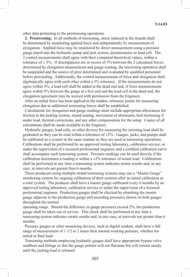
305
5.14.03
other data pertaining to the prestressing operations. 2. Prestressing: In all methods of tensioning, stress induced in the strands shall be determined by monitoring applied force and independently by measurement of elongation. Applied force may be monitored by direct measurement using a pressure gauge piped into the hydraulic pump and jack system, dynamometer or load cell. The 2 control measurements shall agree with their computed theoretical values, within a tolerance of ± 5%. If discrepancies are in excess of 5% between the 2 calculated forces, determined by elongation measurement and gauge reading, the tensioning operation shall be suspended and the source of error determined and evaluated by qualified personnel before proceeding. Additionally, the control measurements of force and elongation shall algebraically agree with each other within a 5% tolerance. If the measurements do not agree within 5%, a load cell shall be added at the dead end and, if force measurements agree within 5% between the gauge at a live end and the load cell at the dead end, the elongation agreement may be waived with permission from the Engineer. After an initial force has been applied to the tendon, reference points for measuring elongation due to additional tensioning forces shall be established. Calculations for elongation and gauge readings must include appropriate allowances for friction in the jacking system, strand seating, movement of abutments, bed shortening if under load, thermal corrections, and any other compensation for the setup. Copies of all calculations shall be made available to the Engineer. Hydraulic gauges, load cells, or other devices for measuring the stressing load shall be graduated so they can be read within a tolerance of ±2%. Gauges, jacks, and pumps shall be calibrated as a system in the same manner as they are used in tensioning operations. Calibrations shall be performed by an approved testing laboratory, calibration service, or under the supervision of a licensed professional engineer, and a certified calibration curve shall accompany each tensioning system. Pressure readings can be used directly if the calibration determines a reading is within a ±2% tolerance of actual load. Calibrations shall be performed at any time a tensioning system indicates erratic results and, in any case, at intervals not greater than 6 months. Those producers using multiple strand tensioning systems may use a “Master Gauge” monitoring system for ongoing calibration of their systems after an initial calibration as a total system. The producer shall have a master gauge calibrated every 6 months by an approved testing laboratory, calibration service or under the supervision of a licensed professional engineer. Production gauges shall be checked by plumbing the master gauge adjacent to the production gauge and recording pressures shown on both gauges throughout the normal operating range. Should the difference in gauge pressures exceed 2%, the production gauge shall be taken out of service. This check shall be performed at any time a tensioning system indicates erratic results and, in any case, at intervals not greater than 6 months. Pressure gauges or other measuring devices, such as digital readout, shall have a full range of measurement of 1 1/2 to 2 times their normal working pressure, whether for initial or final load. Tensioning methods employing hydraulic gauges shall have appropriate bypass valve snubbers and fittings so that the gauge pointer will not fluctuate but will remain steady until the jacking load is released.

306
5.14.03
In all methods of pretensioning, the load shall be applied in 2 increments. An initial load is applied to the individual strands to straighten them, eliminate slack, and provide a starting or reference point for measuring elongation. The final load is then applied for which elongation of strands is computed and measured. This method of operation shall be mandatory except as noted below in multiple strand tensioning. Initial tensioning shall not exceed 15% of the specified tensioning force, or 3,000 lb., whichever is greater. In single‑strand tensioning, the initial and final loads may be applied in immediate succession on each strand. At the completion of initial tension, reference marks shall be established from which elongation by final tensioning forces can be measured. Elongations shall then be accurately measured from these reference points. Elongations shall be measured as outlined hereinafter. Elongation measurement shall take into account all operational losses and compensations in the tensioning system. A. Final Stressing of Straight Strands: (1) Single-strand tensioning: After application of the initial load and
establishment of reference marks for measuring elongation, the full strand load shall be applied. Loads indicated by gauging systems shall control the tensioning, with elongation checked on every strand. An exception is the case of a completely open bed with no headers or other possible sources of friction. In such instances, strand elongation shall be checked on only the first and last strands and 10% of all others.
(2) Multiple-strand tensioning: Following application of initial stress and seating of each strand on the anchorage header, reference marks shall be established for measuring elongation and slippage. Reference marks for slippage shall be made by marking a straight line across the strands in each row along the face of the anchorage. For uniform application of load to strands, the face of anchorage at final load must be in a plane parallel to its position under initial load. Parallel movement shall be verified by measurement of movement on opposite sides of the anchorage and a check of its plumb position before and after application of the final load.
B. Final Stressing of Draped Strands: Draped pretensioning strands may be finally stressed by any of the following methods: (1) Partial stressing and subsequent strains: In this method, the strands shall be
tensioned in a straight position or on a partially draped trajectory to a predetermined, intermediate stress value between initial and final stress. The final stress shall be induced by strains resulting from lifting or depressing strands at all other points of change in strand alignment. Final position and stress shall be offset symmetrically about the center of the setup to distribute friction evenly. Stress and elongation shall be measured as specified for the intermediate stress value. Suitable stress measurements at each anchorage at each end of the bed shall verify calculated strand stresses within 5%.
(2) Final stressing in draped position: In this method the strands are stressed to final value in their draped position for the full length of the bed. The strands shall pass over devices which effectively minimize friction at all deflection points. Stress and elongation shall be measured as specified.
When final stressing is done by jacking strands from an end of the bed, even when

307
5.14.03
that tensioning is within tolerance, the force shall be measured on at least 2 strands at the far end. This force shall not be below the theoretical values by more than 5%. If the theoretical elongation has not been attained at an end of the bed when the force, as indicated by pressure gauge or load cell, is exceeded by 5%, the strand shall be jacked from the other end of the bed to the theoretical elongation. If this requires an overstress as indicated by the gauge in excess of 5% overload, the number of deflection points on the bed shall be reduced until the elongation can be attained with not more than 5% overload or the hardware shall be improved to reduce friction. Remaining deflection points shall then be achieved as outlined. If elongation is not obtained within 5% tolerance when theoretical force has been applied, the strand may be temporarily overstressed to overcome friction. Overstress shall not exceed 80% of the specified tensile strength of the strand. Strands shall not be seated in this overstress condition. Provision shall be made to reduce the force on the strand before anchorage. Anchorage by seating of strand into chucks shall be done within 5% tolerance of theoretical force. Stress shall not be transferred to pretensioned members until concrete strength, as indicated by test cylinders or any other properly calibrated nondestructive test technique, is in accordance with specified transfer strength. If concrete has been heat-cured, detensioning shall be performed immediately following the curing period while the concrete is still warm and moist. In all detensioning operations, the prestressing forces shall be kept nearly symmetrical about the vertical axis of the member and shall be applied in a manner that will minimize sudden shock or loading. Maximum eccentricity about vertical axis of the member shall be limited to 10% of the strand group. Limitation of vertical axis eccentricity shall be at the initial cutting of strands at the ends of the bed and as strands are cut between members in the setup. For unusual shapes and heavily stressed shapes, production drawings shall show detensioning procedures. Forms, ties, inserts, or other devices that would restrict longitudinal movement of the members along the bed shall be removed or adequately loosened. Hold-downs shall be removed at the appropriate time for the product and setup. Alternately, detensioning shall be performed in such a manner sequence that longitudinal movement is precluded. In a single strand detensioning, both ends of the bed shall be released simultaneously and symmetrically to minimize sliding of members. The sequence used for detensioning strands shall be according to an approved pattern and schedule that keeps the stresses nearly symmetrical about the vertical axis of the members as specified above. In multiple strand detensioning, strands shall be released simultaneously by hydraulically releasing the jack. The total force shall be taken from the header by the jack, then released gradually. The overstress required to loosen lock nuts or other anchoring devices at the header shall not exceed the force in the strand by 5%. The maximum permissible time for holding tensioned strands in the bed before starting concrete placement is 36 hours. Prestressing details that have been approved by the Engineer shall not be deviated from unless details of such deviations are approved in advance of use. The approval by the Engineer of any proposed method, materials, or equipment shall not relieve the

308
5.14.03
Contractor of full responsibility for successfully completing the prestressing operations in accordance with the requirements of these specifications. 3. Forms: The forms for the beams and deck units shall be of substantial construction. A firm compressible material as indicated on the approved shop drawings, shall form the bottom of the casting bed near the ends of the beams in order that cracking and chipping of the beams will be minimized at the time of load transfer. A minimum concrete cover of 1 1/2 in must be maintained for prestressing strands by the use of approved spreaders or by bundling in areas adjacent to openings, cavities, or inserts. Stirrups and ties shall have a minimum cover of 1 in at these locations. Side forms carrying no load may be removed after 24 hours with the permission of the Engineer or after the concrete has reached the strength required at time of transfer (f’ci). 4. Placing Concrete: Concrete shall not be deposited in the forms until the Engineer has inspected the placing of the prestressing elements and reinforcing steel, including all other cast-in-place components, and has given approval thereof. Concrete shall not be deposited into the forms when the ambient temperature is below 40°F or above 100°F, unless adequate heating or cooling procedures have been previously approved by the Engineer. The concrete temperature shall be 60°F to 90°F at the time of placement. At no time will truck-mixed or transit-mixed concrete be allowed. Production during the winter season, from November 15 to March 15 inclusive, will be permitted only on beds located in a completely enclosed structure of suitable size and dimension that provides a controlled atmosphere for the protection of the casting operation and the product. Outside concreting operations will not be permitted during rainfall unless the operation is completely under cover. Void forms shall be held in place against uplift or lateral displacement during the placing and vibrating of the concrete by substantial wire ties or other satisfactory means as approved by the Engineer. The concrete shall be vibrated internally, or externally, or both, as ordered by the Engineer. The vibrating shall be done with care in such a manner as to avoid displacement of reinforcing steel, prestressing elements, voids, forms, or other components. There shall be no interruption in the placing of any of the members. Concrete shall be carefully placed in the forms and vibrated sufficiently to produce a surface free from imperfections such as honeycombing, segregation, cracking, or checking. Any deficiencies noted in the members may be cause for rejection. 5. Finishing: Prestressing elements shall be recessed 1/8 in to 1/4 in into the member. The recess shall be patched with material approved by the Engineer. When the patch material has cured, it shall be coated with a waterproof material approved by the Engineer. Special care shall be given to the finishing of exposed surface areas. The surface area of all shear keys shall be blast cleaned. Additional finishing of members shall be as shown on the plans or as otherwise directed by the Engineer. Formed surfaces shall not be finished in any manner unless permitted by the Engineer. Top surfaces shall be finished as follows:
Beams: The laitance shall be removed from the top of the beams. After the concrete has set sufficiently to prevent tearing loose of coarse aggregate, the top surface shall be transversely raked. Deck Units: Deck units in structures that will have a bituminous concrete wearing

309
5.14.04
surface shall be given a float finish on the top surface as specified in Subarticle 6.01.03-10. Where the deck units are used with a concrete deck, the top surface of the units shall be finished in accordance with the above requirements for beams.
6. Test Cylinders: During the casting of each prestressed member, the Contractor shall make test cylinders under the supervision of a representative of the Department. The dimensions, type of cylinder mold and number of cylinders shall be specified by the Engineer. At least 4 test cylinders shall be cured by the same methods employed for the curing of the member and shall be used to verify the strength (f’ci) required for transfer of the prestressing load. The remaining test cylinders shall be used to determine when the required 28-day strength (f’c) has been achieved. Failure of any of the 28-day test cylinders to meet 90% of the minimum compressive strength or failure of the average to meet the full minimum compressive strength requirement may be cause for rejection. 7. Curing: Unless otherwise shown on the plans or indicated in the special provisions, prestressed concrete members shall be cured in accordance with the latest edition (including Interim Specifications) of “AASHTO Standard Specifications for Highway Bridges, Division II.” 8. Patching: No patching of the completed members will be allowed unless permitted by the Engineer. The Contractor’s proposal for methods and materials to be used in the patching operation shall be submitted to the Engineer for approval. Failure to do so may be cause for rejection. 9. Joining Deck Units: The transverse tie strands shall be installed and tensioned to the total force shown on the plans. When the required length of the transverse tie strand is greater than 13 ft, the strands shall be checked after a period of 36 hours and retensioned if necessary to the required force. After the check and required retensioning, the longitudinal shear keys between the adjacent deck units and the recesses at the ends of the transverse tie strands shall be filled with non‑shrink grout meeting the requirements of Article M.03.05. Before the non-shrink grout is placed, the key spaces and recesses shall be thoroughly cleaned. If Portland cement non-shrink grout is used, the key areas shall be thoroughly wetted prior to placement of the grout. The Portland cement grout shall be mixed and placed as directed by the Engineer. If premixed non-shrink grout is used, the key areas shall be prepared and the grout mixed and placed as recommended by the grout manufacturer. Where the top surfaces of the adjacent deck units do not match, the grout shall be sloped to form a smooth transition. No superimposed dead or live loads shall be applied to the adjacent deck units until the non-shrink grout in the longitudinal shear keys and recesses has cured. The curing time for Portland cement non-shrink grout shall be 7 days. The curing time for premixed non-shrink grout shall be considered the time when the grout has attained a compressive strength of 4,500 psi and as recommended by the grout manufacturer. 10. Quality Control: Quality control shall be the responsibility of the fabricator. Quality assurance shall be the prerogative of the State. At no expense to the State, there shall be provided a separate office building or room having an area of at least 80 s.f., with the least dimension to be 6 ft. This office shall be equipped with a suitable heating system capable of maintaining a minimum temperature of 65°F. It shall be clean and free of extraneous material and equipment. Sufficient light and ventilation shall be provided.

310
5.14.04
During the summer months, the office temperature shall not exceed the ambient temperature. A desk and chair shall be provided for the inspector, and a telephone shall be within audible range of the office. The quality of fabrication and construction and the dimensional tolerance of the prestressed members shall conform to the limits specified in the “Manual for Quality Control for Plants and the Production of Precast Prestressed Concrete Products (MNL‑116‑Latest Edition)” published by PCI, unless otherwise specified herein, except that:1. The tolerance for horizontal alignment shall be measured from a straight line
intersecting the ends of beam at either or both faces of top and bottom flanges.2. The tolerance for beam seat bearing area shall apply to the entire width of the
member. Deviations in excess of the permissible tolerances will be cause for rejection.
11. Marking: Beams and deck units shall be identified as to Project, structure, casting date, and position in the structure by means of a non-corrosive metal tag embedded permanently in the bottom of the members at the mark end. 12. Inspection: The provisions of Subarticle 6.03.03-3 (Shop Fabrication), (a) Notification, shall apply to the steel items, and the pertinent requirements contained herein shall apply equally to the work performed in the plant producing the precast concrete products. 13. Lifting Hooks: The number and location of lifting hooks shall be as shown on plans. 14. Special Considerations: Before erection, the Contractor shall recess, clean, patch and paint ends of strands in a neat and workmanlike manner. Projecting fins and surface imperfections shall be removed. The bearing area at the bottom ends of the beams and deck units must lie in the same plane as the grade of the beam or deck units in their final erected position after application of full dead load. Prior to erection, any deviations of the bearing area from a true plane shall be remedied by grinding, by applying an approved epoxy mortar, or by a combination of both as approved by the Engineer. 15. Handling and Storage: Care shall be taken during storage, transporting, hoisting, and handling of all prestressed members to prevent cracking or damage. Members damaged by improper storing, transporting, or handling shall be replaced by the Contractor at its expense. All storage and handling operations shall be as directed by the Engineer. After erection, any marking, chipping, or spalling sustained by the member shall be removed or repaired in a neat and workmanlike manner as directed by the Engineer. 16. Methods and Equipment: The Contractor shall be solely responsible for the adequacy of his erection scheme and for all details of plant, falsework, and other equipment and material necessary to carry it out. The Contractor’s responsibility includes the investigation of erection stresses. The results of this investigation, including computations, shall be submitted to the Engineer.
5.14.04—Method of Measurement: This work will be measured for payment by the actual number of linear feet of prestressed beams or deck units installed and accepted. Measurement will be made along the longitudinal center line of each member.

311
5.21.03
5.14.05—Basis of Payment: Payment for this work will be made at the Contract unit price per linear foot for “Prestressed Beams—Pretensioned, Type ( )” or “Prestressed Deck Units (size)” as shown on the plans, completed and accepted, including all materials, equipment, tools, and labor incidental thereto, and without differentiation as to interior or exterior members.
Pay Item Pay UnitPrestressed Beams—Pretensioned Type ( ) l.f.Prestressed Deck Units (size) l.f.
SECTION 5.21ELASTOMERIC BEARING PADS
5.21.01—Description: Work under this item shall consist of furnishing and installing elastomeric bearing pads and all other necessary materials and equipment to complete the work as shown on the plans.
5.21.02—Materials: Elastomeric bearing pads and adhesive for bonding the pads to steel shall meet the requirements of Article M.17.01.
5.21.03—Construction Methods: 1. Shop Drawings: Before fabricating any materials, the Contractor shall submit drawings to the Engineer for approval in accordance with Subarticle 1.05.02-3. These drawings shall include but not be limited to the following information:1. name of manufacturer 2. complete details of the pads3. pertinent material designations
2. Setting the bearing pads: The Contractor shall set the elastomeric bearing pads in accordance with the following requirements:
(a) Concrete bearing areas: The bearing areas of the masonry upon which the elastomeric bearing pads are to rest shall be carefully finished, by grinding if necessary, to a smooth, even level surface of the required elevation, and shall show no variations from a true plane greater than 1/16 in over the entire area upon which the elastomeric bearing pads are to rest.
(b) Metal bearing areas: The elastomeric bearing pads shall be bonded to steel masonry plates or to steel sole plates or girders where indicated on plans or when directed by the Engineer.
3. There shall be uniform bearing between the bottom of the beam or steel sole plate and the elastomeric bearing pad and between the elastomeric bearing pad and the concrete seat or steel base plate, after application of full dead load. Also after application of full dead load, there shall be uniform deflection of the elastomeric bearing pad. 4. The elastomeric bearing pads shall be bonded to the steel plates or beams as shown on Contract plans or where directed. All contact surfaces to which the adhesive is to be applied shall be free of oil, paint, lacquer, galvanizing, mill scale, and rust. Primer, if required, and adhesive shall be applied in strict accordance with the manufacturer’s printed instructions. The prefabricated pads shall be pressed to the steel plate under sufficient pressure to provide full intimate contact until the adhesive has set. 5. The adhesive shall be mixed in strict accordance with the manufacturer’s printed directions.

312
5.21.04
5.21.04—Method of Measurement: This work will be measured for payment by the number of cubic inches of elastomeric bearing pads, installed and accepted.
5.21.05—Basis of Payment: This work will be paid for at the Contract unit price per cubic inch of “Elastomeric Bearing Pads,” complete in place, which price shall include all materials, equipment, tools and labor incidental thereto, including all the cost of furnishing test pads.
Pay Item Pay UnitElastomeric Bearing Pads c.i.
SECTION 5.22ELASTOMERIC COMPRESSION SEAL
5.22.01—Description5.22.02—Materials5.22.03—Construction Methods5.22.04—Method of Measurement5.22.05—Basis of Payment
5.22.01—Description: Under this item the Contractor shall furnish and install elastomeric compression seal with a lubricant-adhesive in joints as shown, dimensioned and detailed on the plans, or as ordered by the Engineer.
5.22.02—Materials: The materials for this work shall meet the requirements of Article M.17.02.
5.22.03—Construction Methods: The Contractor shall arrange to have a representative of the manufacturer knowledgeable in the methods of installation present at the time of the first installation. The Contractor shall also arrange to have the representative of the manufacturer present at such other times as the Engineer may require. Shop Drawings: Before fabricating any materials, the Contractor shall submit shop drawings to the Engineer in accordance with Subarticle 1.05.02-3. These drawings shall include but not be limited to the following information:1. complete details of the method, materials and equipment proposed to be used2. name of manufacturer3. complete details of the compression seal and method of notching at bends where
necessary, showing length and depth of notch Joint Preparation: Where the concrete has spalled, cracked or chipped adjacent to the joint, the Contractor shall make the necessary repairs with an approved material to the satisfaction of the Engineer and at no additional cost to the State. Immediately before placing the compression seal, the entire joint shall be thoroughly cleaned of all scale, loose concrete, dirt, dust and foreign matter to the satisfaction of the Engineer. The portion of the joint outside of the traveled way, including the mall and all curb areas shall be masked sufficiently on each side of the joint to prevent the lubricant‑ adhesive from coming in contact with the exposed surfaces. Installation: The compression seal shall be furnished and installed continuous in length for the full length of the transverse joint as shown on the plans. Cutting shall be performed in accordance with the methods and procedures as indicated on the shop drawings.

313
5.22.05
The compression seal shall be installed by special hand or machine tools in the joint with the lubricant-adhesive after the concrete in curb areas adjacent to the joint has cured. The lubricant-adhesive shall be applied to the sides of the joint or to the sides of the compression seal or to both such that the full area in contact between the compression seal and the joint shall be covered with the lubricant-adhesive. Immediately prior to installation, the compression seal shall be wiped with a suitable solvent to remove any dirt, dust, protective coating or any foreign matter. The compression seal shall be installed in a compressed condition and shall at all times be recessed to the depth indicated on the plans. The sides of the compression seal shall be fully in contact with the sides of the joint and the “V” section of the top of the compression seal shall be folded so that it projects inwards towards the inner web sections. Any lubricant-adhesive on the top of the compression seal shall be removed immediately. Any compression seal that is punctured or ruptured shall be removed in its entirety and replaced by the Contractor at no additional cost to the State.
5.22.04—Method of Measurement: This work will be measured for payment by the actual number of linear feet of elastomeric compression seal, of the various widths, installed and accepted.
5.22.05—Basis of Payment: This work will be paid for at the Contract unit price per linear foot for “(Size) Elastomeric Compression Seal” of the various widths, complete in place, which price shall include all material including lubricant-adhesive, splicing, equipment, tools, and labor incidental thereto.
Pay Item Pay Unit(Size) Elastomeric Compression Seal l.f.

314
6.01.01
SECTION 6.01CONCRETE FOR STRUCTURES
6.01.01—Description6.01.02—Materials6.01.03—Construction Methods6.01.04—Method of Measurement6.01.05—Basis of Payment
6.01.01—Description: This item shall include concrete for use in bridges and culverts, walls, catch basins, drop inlets and other incidental construction as required. The concrete shall be composed of Portland cement, pozzolans, fine and coarse aggregate, admixtures and water, prepared and constructed in accordance with these specifications, at the locations and of the form dimensions and class shown on the plans, or as directed by the Engineer. The use of concrete from dry batch or central mixed plants is permitted for all concrete mixtures.
6.01.02—Materials: The materials for this work shall meet the requirements of Section M.03.
6.01.03—Construction Methods: 1. Falsework and Forms: Falsework is considered to be any temporary structure which supports structural elements of concrete, steel, masonry or other material during the construction or erection. Forms are to be considered to be the enclosures or panels which contain the fluid concrete and withstand the forces due to its placement and consolidation. Forms may in turn be supported on falsework. This work shall consist of the construction and removal of falsework and forms that are designed by the Contractor in the execution of the work, and whose failure to perform properly could adversely affect the character of the Contract work or endanger the safety of adjacent facilities, property, or the public. Falsework and forms shall be mortar tight and of sufficient rigidity and strength to safely support all loads imposed and to produce in the finished structure the lines and grades indicated in the Contract. Forms shall also impart the required surface texture and rustication, and shall not detract from the uniformity of color of the formed surfaces. Forms shall be of wood, steel or other material approved by the Engineer. (a) Design: The design of falsework and formwork shall be as specified in the AASHTO Guide Design Specifications for Bridge Temporary Works, or to other established and generally accepted design codes such as ACI Standard ACI 347-Recommended Practice for Concrete Formwork or specific form or falsework manufacturer specifications. When other than new or undamaged materials are used, appropriate reductions in allowable stresses, and decreases in resistance factors or imposed loads shall be used for design. (b) Loads: The design of the falsework and forms shall be based on load factors specified in the AASHTO LRFD Bridge Design Specifications and all applicable load combinations shall be investigated. The design load for falsework shall consist of the sum of appropriate dead and live vertical loads and any horizontal loads. As a minimum, dead loads shall include the weight of the falsework and all construction material to be supported. The combined unit weight of concrete, reinforcing and pre-

315
6.01.03
stressing steel, and forms that is supported shall be assumed to be not less than:1. Normal-weight (normal-density) concrete: 0.16 kip/ft3 2. Lightweight (low-density) concrete: 0.13 kip/ft3
Live loads shall consist of the actual weight of any equipment to be supported, applied as concentrated loads at the points of contact and a uniform load of not less than 0.02 kip/ft2 applied over the area supported, plus 0.075 kip/ft applied at the outside edge of deck overhangs. The horizontal load used for the design of the falsework bracing system shall be the sum of the horizontal loads due to equipment; construction sequence including unbalanced hydrostatic forces from fluid concrete and traffic control devices; stream flow, when applicable; and an allowance for wind. However, in no case shall the horizontal load to be resisted in any direction be less than 2% of the total dead load. For post-tensioned structures, the falsework shall also be designed to support any increase in or redistribution of loads caused by tensioning of the structure. Loads imposed by falsework onto existing, new, or partially completed structures shall not exceed those permitted in 6.01.03-12, Application of Loads. (c) Working Drawings: The working drawings for falsework and formwork shall be prepared in accordance with Article 1.05.02 whenever the falsework or formwork exceeds 14.0 ft in height or whenever vehicular, marine, or pedestrian traffic may travel under or adjacent to the falsework or formwork. Working drawings shall include the sequence, method and rate of placement of the concrete. Manufacturer catalog cuts or written installation procedures shall be provided for any clips, braces, hangers or other manufactured parts used with the formwork or falsework. (d) Construction: Forms and falsework shall be built true to lines and grades shall be strong, stable, firm, mortar‑tight and adequately braced or tied, or both. They shall be designed and constructed to withstand all loads and pressures including those imposed by plastic concrete, taking full account of the stresses due to the rate of placement, effect of vibration and conditions brought about by construction methods. Forms and falsework shall be constructed to compensate for variations in camber of supporting members and allow for deflections. Falsework and formwork shall be chamfered at all sharp corners, unless otherwise ordered or permitted, and shall be given a slight bevel or draft in the case of projections to ensure satisfactory removal. Materials for falsework and formwork and their supports, ties and bracing, shall be of the type, quality and strength to achieve the structural requirements. Form material in contact with concrete shall provide the finished concrete surface smoothness as specified in 6.01.03‑10, Finishing Concrete Surfaces, and shall have a uniform appearance. Falsework and formwork shall be treated with form oil or other release agent approved by the Engineer before the reinforcing steel is placed or self-releasing forms approved by the Engineer may be used. Release agents which will adhere to or discolor the concrete shall not be used. Falsework and formwork for concrete surfaces exposed to view shall produce a smooth surface of uniform texture, free of voids, indentations, protrusions and bulges. Panels lining falsework and formwork shall be arranged so that the joint lines form a symmetrical pattern conforming to the general lines of the structure. The same type of form-lining material shall be used throughout each element of a structure. Falsework and

316
6.01.03
formwork shall be sufficiently rigid so that the undulation of the concrete surface shall not exceed 1/4 in when checked with a 4 ft straightedge or template. For non‑exposed surfaces the falsework and formwork shall be sufficiently rigid so that the undulation of the concrete surface shall not exceed 1/2 in when checked with a 4 ft straightedge or template. Metal ties and anchors to hold the falsework and formwork in alignment and location shall be so constructed that the metal work can be removed to a depth of at least 2 in from the concrete surface without damage to the concrete. All cavities resulting from the removal of metal ties shall be filled after removal of forms with cement mortar of the same proportions used in the body of the work or other materials approved by the Engineer, and the surface finished smooth and even, and if exposed in the finished work, shall be similar in texture and color of adjacent surfaces. With permission of the Engineer, the Contractor need not remove from the underneath side of bridge decks portions of metal devices used to support reinforcing steel providing such devices are of material, or are adequately coated with material, that will not rust or corrode. When coated reinforcing steel is required, all metal ties, anchorages, or spreaders that remain in the concrete shall be of corrosion-resistant material or coated with a dielectric material. Forms shall be clean and clear of all debris. For narrow walls and columns where the bottom of the form is inaccessible, an access opening will be allowed in the form and falsework for cleaning out extraneous material. (e) Date of Completion: The year in which the superstructure is completed in its entirety shall be cast in at least 2 places as shown on the plans unless otherwise ordered by the Engineer. The date shall be placed in diagonally opposite ends of the bridge parapets or as designated by the Engineer. The reverse molds for the date shall be furnished by the Contractor. (f) Bridge Decks: After erection of beams and prior to placing falsework and forms, the Contractor shall take elevations along the top of the beam at the points shown on the plans or as directed by the Engineer. The Contractor shall calculate the haunch depths and provide them to the Engineer a minimum of 7 days prior to installing the falsework and forms. The Contractor shall also provide calculations for the setting of the overhang brackets based on the final beam deflection. These calculations shall be based on the final proposed deck grade and parapet elevations. Falsework or formwork for deck forms on girder bridges shall be supported directly on the girders so that there will be no appreciable differential settlement during placing of the concrete. Girders shall be either braced and tied to resist any forces that would cause rotation or torsion in the girders caused by the placing of concrete for diaphragms or decks, or shown to be adequate for those effects. Unless specifically permitted, welding of falsework support brackets or braces to structural steel members or reinforcing steel shall not be allowed. (g) Stay-In-Place Metal Forms for Bridge Decks: These forms may be used if shown in the Contract or approved by the Engineer. Prior to the use of such forms and before fabricating any material, the Contractor shall submit working drawings to the Engineer for review in accordance with Article 1.05.02. These drawings shall include the proposed method of form construction, erection plans including placement plans, attachment details, weld procedure(s), material lists, material designation, gage of all materials, and the details of corrugation. Also, copies of the form design computations shall be

317
6.01.03
submitted with the working drawings. Any changes necessary to accommodate stay-in-place forms, if approved, shall be at no cost to the Department. The metal forms shall be designed on the basis of the dead load of the form, reinforcement and the plastic concrete, including the additional weight of concrete [considered to be equivalent to the weight imposed by an additional concrete thickness equal to 3% of the proposed deck thickness, but not to exceed 0.3 in] due to the deflection of the metal forms, plus 50 psf for construction loads. The allowable stress in the corrugated form and the accessories shall not be greater than 0.725 times the yield strength of the furnished material and the allowable stress shall not exceed 36,000 psi. The span for design and deflection shall be the clear distance between edges of the beams or girders less 2 in and shall be measured parallel to the form flutes. The maximum deflection under the weight of plastic concrete, reinforcement, and forms shall not exceed 1/180 of the form span or 0.5 in, whichever is less. In no case shall the loading used to estimate this deflection be less than 120 psf. The permissible form camber shall be based on the actual dead load condition. Camber shall not be used to compensate for deflection in excess of the foregoing limits. The form support angles shall be designed as a cantilever and the horizontal leg of the form support angle shall not be greater than 3 in. No stay-in-place metal forms shall be placed over or be directly supported by the top flanges of beams or girders. The form supporting steel angles may be supported by or attached to the top flanges. Stay-in-place metal forms shall not be used in bays where longitudinal slab construction joints are located, under cantilevered slabs such as the overhang outside of fascia members, and bridges where the clearance over a salt-laden body of water is less than 15 ft above mean high water level. Welding to the top flanges of steel beams and girders is not permitted in the areas where the top flanges are in tension, or as indicated on the plans. Alternate installation procedures shall be submitted addressing this condition. Drilling of holes in prestressed concrete beams or the use of power-actuated tools on the prestressed concrete beams for fastening of the form supports will not be permitted. Welding of the reinforcing steel to the prestressed units is not permitted. All edges of openings cut for drains, pipes, and similar appurtenances shall be independently supported around the entire periphery of the opening. All fabricated stay-in-place metal forms shall be unloaded, stored at the Project Site at least 4 in above the ground on platforms, skids or other suitable supports and shall be protected against corrosion and damage and handled in such a manner as to preclude damage to the forms. Damaged material shall be replaced at no additional cost to the State. Any exposed form or form support metal where the galvanized coating has been damaged, shall be thoroughly cleaned, wire brushed, then coated with 2 coats of Zinc Dust – Zinc Oxide primer, FS No. TT-P-641d, Type II or another product acceptable to the Engineer. The forms shall be installed from the topside in accordance with the manufacturer’s recommended installation procedures. The form supports shall ensure that the forms retain their correct dimensions and positions during use at all times. Form supports shall provide vertical adjustment to maintain design slab thickness at the crest of corrugation, to compensate for variations in camber of beams and girders and to allow for deflections. Stay-in-place metal forms shall have a minimum depth of the form valley equal to 2 in.

318
6.01.03
The forms shall have closed tapered ends. Lightweight filler material shall be used in the form valleys. All field cutting shall be done with a steel cutting saw or shears including the cutting of supports, closures and cutouts. Flame cutting of forms is not permitted. All welding shall be performed by Department certified welders in accordance with the Welding Subarticle in Section 6.03. Welding of forms to supports is not permitted. The steel form supports shall be placed in direct contact with the flange of stringer or floor beam flanges and attached by bolts, clips, welding where permitted, or other approved means. Form sheets shall not be permitted to rest directly on the top of the stringer or floor beam flanges. The forms shall be securely fastened to form supports with self-drilling fasteners and shall have a minimum bearing length of 1 in at each end. In the areas where the form sheets lap, the form sheets shall be securely fastened to each other by fasteners at a maximum spacing of 18 in. The ends of the form sheets shall be securely attached to the support angles with fasteners at a maximum spacing of 18 in or 2 corrugation widths, whichever is less. The depth of the concrete slab shall be as shown on the plans and the corrugated forms shall be placed so that the top of the corrugation will coincide with the bottom of the deck slab. No part of the forms or their supports shall protrude into the slab. All reinforcement in the bottom reinforcement mat shall have a minimum concrete cover of 1 in unless noted otherwise on the plans. The completed stay‑in‑place metal form system shall be sufficiently tight to prevent leakage of mortar. Where forms or their installation are unsatisfactory in the opinion of the Engineer, either before or during placement of the concrete, the Contractor shall correct the defects before proceeding with the work. (h) Construction Joints: Construction joints other than those shown on the plans will not be permitted without prior approval of the Engineer. In joining fresh concrete to concrete that has already set, the work already in place shall have all loose and foreign material removed, and the surface roughened and thoroughly drenched with water. All reinforcing steel shall extend continuously through joints. Where unplanned construction joints may be needed, they shall be constructed as directed by the Engineer. (i) Expansion and Contraction Joints: Expansion and contraction joints shall be constructed at the locations and in accordance with the details specified in the Contract. The forming of joint openings shall be dimensioned in accordance with the joint manufacturer’s design requirements. Joints include open joints, filled joints, joints sealed with sealants, joints reinforced with steel armor plates or shapes, paraffin coated joints, and joints with combinations of these features. Open joints shall be placed at locations designated on the plans and shall be formed by the insertion and subsequent removal of templates of wood, metal or other suitable material. The templates shall be so constructed that their removal may be readily accomplished without damage to the work. Filled joints shall be made with joint filler, the materials for which shall meet the requirements of the plans and of these specifications. For mechanical joint systems, the concrete shall be placed in such a manner that does not interfere with the movement of the joint. (j) Pipes, Conduits and Utility Installations: The Contractor shall coordinate the installation of pipes, conduits and utilities as shown on the plans and in accordance with

319
6.01.03
the Contract or as directed by the Engineer. The openings accommodating such pipe, conduit and utility installations shall be incorporated into the formwork by the Contractor. (k) Anchorages: Anchor bolts and systems shall be set to the requirements of the plans and Contract. Anchor bolts and systems shall be clean and free of dirt, moisture or other foreign materials at the time of installation. The anchor bolts and systems shall be installed prior to placing concrete. With the Engineer’s approval, the Contractor may install anchorages after placement and setting of the concrete or in formed holes. The anchorages shall be installed into drilled or formed holes having a diameter and a depth suitable to receive the bolts in accordance with the grout manufacturer’s requirements. Such holes shall be located to avoid damage to the existing reinforcement. All holes shall be perpendicular to the plane surface. The Contractor shall take every precaution necessary to prevent damage to the concrete due to freezing of water or grout in anchor bolt holes. (l) Ornament or Reverse Moulds: Ornamental work, when so noted on the plans, shall be formed by the use of reverse moulds. These moulds shall be produced by a qualified manufacturer approved by the Engineer. They shall be built in accordance with the general dimensions and appearance shown on the plans. The Contractor shall submit all detailed drawings, models, or carvings for review by the Engineer before the moulds are made. The Contractor shall be responsible for their condition at all times, and shall be required to remove and replace any damaged or defective moulds at no additional cost to the State. The surfaces of the moulds shall be given a coating of form release agent to prevent the adherence of concrete. Any material which will adhere to or discolor the concrete shall not be used. Form Liners, if required, shall be installed as specified elsewhere. (m) Removal of Falsework and Forms: The Contractor shall consider the location and character of the structure, the weather, the materials used in the mix, and other conditions influencing the early strength of the concrete when removing forms and falsework. Methods of removal likely to cause damage to the concrete surface shall not be used. Supports shall be removed in such a manner as to permit the structure to uniformly and gradually take the stresses due to its own weight. For structures of 2 or more spans, the sequence of falsework release shall be as specified in the Contract or approved by the Engineer. Removal shall be controlled by field‑cured cylinder tests. The removal shall not begin until the concrete has achieved 75% of the design compressive strength. To facilitate finishing, side forms carrying no load may be removed after 24 hours with the permission of the Engineer, but the curing process must be continued for 7 days.

320
6.01.03
When the results of field‑cured cylinder tests are unavailable, the following periods, exclusive of days when the temperature drops below 40°F, may govern the removal of forms:
Form Removal RequirementsStructure Element Minimum Time Period
Arch Centers, centering under beams,pier caps, and unsupported elements 14 days
Slabs on grade, Abutments and Walls 24 hoursColumns 2 daysBridge Decks 28 days
The Contractor may submit for review and approval by the Engineer, alternate methods to determine the in-place strength of the concrete for removal of forms and falsework. 2. Protection from Environmental Conditions: The concrete shall be protected from damage due to weather or other environmental conditions during placing and curing periods. In-place concrete that has been damaged by weather conditions shall be either repaired to an acceptable condition or removed and replaced as determined by the Engineer. (a) Rain Protection: The placement of concrete shall not commence or continue unless adequate protection satisfactory to the Engineer is provided by the Contractor. (b) Hot Weather Protection: When the ambient air temperature is above 90°F, the forms, which will come in contact with the mix shall be cooled to below 90°F for a minimum of 1 hour prior to and 1 hour after completion of the concrete placement by means of a water spray or other methods satisfactory to the Engineer. (c) Cold Weather Protection: When there is a probability of ambient air temperature below 40°F during placement and curing, a Cold-Weather Concreting Plan shall be submitted to the Engineer for review and comment. The Plan shall detail the methods and equipment, including temperature measuring devices that will be used to ensure that the required concrete and air temperatures are maintained, as follows:1. Placement: The forms, reinforcing steel, steel beam flanges, and other surfaces
which will come in contact with the mix shall be heated to a minimum of 40°F, by methods satisfactory to the Engineer, for a minimum of 1 hour prior to, and maintained throughout, concrete placement.
2. Curing: For the first 6 days, considered the initial cure period, the concrete shall be maintained at a temperature of not less than 45°F and the air temperature surrounding the structure shall be maintained at a temperature of not less than 60°F. When the concrete mix includes pozzolans or slag, the initial cure period shall be increased to 10 days. After the initial cure period, the air surrounding the structure shall be maintained above 40° F for an additional 8 days. If external heating is employed, the heat shall be applied and withdrawn gradually and uniformly so that no part of the concrete surface is heated to more than 90°F or caused to change temperature by more than 20°F in 8 hours. The Engineer may reduce or increase the amount of time that the structure must be protected or heated based on an indication of in-place concrete strength acceptable to the Engineer.
(d) Additional Requirements for Bridge Decks: Prior to the application of curing

321
6.01.03
materials, all the concrete placed on bridge decks shall be protected from damage due to rapid evaporation by methods acceptable to the Engineer. During periods of low humidity (less than 60% relative humidity), sustained winds of 25 mph or more, or ambient air temperatures greater than 80ºF, the Contractor shall provide written details of additional measures to be taken during placement and curing. Protection may include increasing the humidity of the surrounding air with fog sprayers and employing wind-breaks or sun-shades. Additional actions may include reduction of the temperature of the concrete prior to placement, scheduling placement during the cooler times of days or nights, or any combination of these actions. (e) Concrete Exposed to Salt Water: No Construction joints shall be formed between the levels of extreme low water and extreme high water or the upper limit of wave action as determined by the Engineer. 3. Transportation and Delivery of Concrete: All material delivered to the Project shall be supplied by a producer qualified in accordance with Section M.03. The producer shall have sufficient plant capacity and trucks to ensure continuous delivery at the rate required to prevent the formation of cold joints. (a) Material Documentation: All vendors producing concrete must have their weigh scales and mixing plant automated to provide a detailed ticket. Delivery tickets must include the following information:
1. State of Connecticut printed on ticket2. Name of producer, identification of plant3. Date and time of day4. Type of material5. Cubic yards of material loaded into truck6. Project number, purchase order number, name of Contractor (if Contractor other
than producer)7. Truck number for specific identification of truck8. Individual aggregate, cement, water weights and any admixtures shall be printed
on plant tickets9. Water/cement ratio, and10. Additional water allowance in gallons based on water/cement ratio for mix
A State inspector may be present to monitor batching or weighing operations. The Contractor shall notify the Engineer immediately if, during the production day, there is a malfunction of the recording system in the automated plant or weigh scales. Manually written tickets containing all required information may be allowed for up to 1 hour after malfunction provided they are signed by an authorized representative of the producer. (b) Transportation of Mixture: Trucks delivering concrete shall be qualified in accordance with Section M.03. If the concrete mix arrives at the Project with a slump lower than allowed by specification, water may be considered as a means to temper concrete to bring the slump back to within specification. This tempering may only be done prior to discharge with the permission of the Engineer. The quantity of water in gallons added to the concrete cannot exceed the allowance shown on the delivery ticket. The concrete shall be completely discharged into the forms within 1-1/2 hours from the batch time stamped on the delivery ticket. This time may be extended if the measured

322
6.01.03
temperature of the concrete is below 90ºF. This time may also be reduced if the temperature of the concrete is over 90ºF. Rejected concrete shall be disposed of by the Contractor at no cost to the State. The addition of chemical admixtures or air entrainment admixtures at the Project Site, to increase the workability or to alter the time of set, will only be permitted if prior approval has been granted by the Engineer. The addition of air entrainment admixtures at the Project Site will only be permitted by the producer’s quality control staff. The Contractor is responsible for follow-up quality control testing to verify compliance with the Specifications. 4. Acceptance Testing and Test Specimens: The Contractor shall furnish the facilities and concrete required for sampling, transport to the testing location in the field, performing field testing and for casting sample cylinders for compressive‑strength determinations. The Department will furnish personnel for sampling and casting Acceptance specimens and the number of specimens required will be determined by the Engineer. The equipment for the Department’s testing is provided for elsewhere in the Contract. (a) Temperature, Air Content and Slump: Field testing in accordance with AASHTO T 23, “Making and Curing Concrete Test Specimens in the Field” will be performed at the point of placement and at a frequency determined by the Engineer. (b) Acceptance Testing and Compressive Strength Specimens: Concrete samples are to be taken at the point of placement into the forms or molds. Representatives of the Engineer will sample the mix.
Standard Mix Class Air Content Slump Concrete
TemperatureA (3300 psi)
6.0 +/- 1.5% 4” +/- 1”
60º-90ºF
C (3300 psi)F (4400 psi)
Modified Standards1 6.0 +/- 1.5%2 4” +/- 1” 2
Special Provision Mix3 As specified As Specified
1 Modifications to Standard Mixes, including mixed placed by pumping, shall be reviewed by the Engineer prior to use. These include but are not limited to the use
of chemical admixtures such as high range water reducing (HRWR) admixtures and the use of coarse aggregate sizes for that class not specified in M.03
2 If the only modification is the addition of HRWR, the maximum allowable slump shall be 7 inches.
3 All concrete mixes with a mix design strength not shown in the table must be approved by the Engineer on a case-by-case basis. Limits on the plastic properties
and strength requirements of these mixes are listed in the Specifications.
The Contractor shall provide and maintain facilities on the Project Site, acceptable to the Engineer, for sampling, transporting the initial sample, casting, safe storage and initial

323
6.01.03
curing of the concrete test specimens as required by AASHTO T 23. This shall include but not be limited to a sampling receptacle, a means of transport of the initial concrete sample from the location of the concrete placement to the testing location, a level and protected area of adequate size to perform testing, and a specimen storage container capable of maintaining the temperature and moisture requirements for initial curing of Acceptance specimens. The distance from the location of concrete placement to the location of testing and initial curing shall be 100 ft or less, unless otherwise approved by the Engineer. The specimen storage container described in this section is in addition to the concrete cylinder curing box provided for elsewhere in the Contract. After initial curing, the test specimens will be transported by Department personnel and stored in the concrete cylinder curing box until they can be transported to the Division of Materials Testing for strength evaluation. (c) Sampling Procedure for Pumping: It is the responsibility of the Contractor to provide concrete that meets specification at the point of placement. Samples of concrete shall be taken at the discharge end of the pump at the point of placement with the exception of underwater concrete. The Contractor may submit an alternate location to provide a sample from the discharge end of the pump with verification showing that the characteristics of the mix will not be altered from that of which would have been attained at the point of placement. The Engineer will review the documentation and other extenuating circumstances when evaluating the request. In the case of underwater concrete the Contractor shall submit the proposed sampling location with the submittals required in Subarticle 6.01.03-6(f).(d)Additionalfieldtesting: Additional field testing such as density and yield measurements may be required at the time of placement as determined by the Engineer. 5. Progression Cylinders and Compressive Strength Specimens: Progression Cylinders outlined in this section are field cured compressive strength specimens taken for information related to when a structure or segment of a structure can be loaded or put into service, adequacy of curing and protection of concrete in the structure, or when formwork or shoring may be removed from the structure. The information produced from strength results of Progression Cylinders will not be considered for acceptance of the concrete. The personnel, equipment, and molds for sampling, casting, curing and testing of Progression Cylinders shall be furnished by the Contractor at no expense to the Department. Sampling, casting, and field curing of the specimens shall be performed in accordance with AASHTO T 23 by an ACI Concrete Field Testing Technician Grade 1 or higher and will be witnessed by a representative of the Department. The sample shall be taken at the point of placement into the forms or molds from the same truck load(s) from which an Acceptance sample is taken. A minimum of 2 cylinder results will be used to determine in-place strength. Compression testing shall be performed in accordance with AASHTO T 22 by personnel approved by the Engineer. A Certified Test Report in accordance with Article 1.06.07 shall be provided to the Engineer reporting the Progression Cylinder test results. A copy of the results of the compressive strength testing shall be provided to the Engineer at least 24 hours prior to

324
6.01.03
any Project activity that the results may control. 6. Handling and Placing Concrete: Concrete shall be handled, placed, and consolidated by methods acceptable to the Engineer that will not segregate the mix and shall result in a dense homogeneous concrete. The methods used shall not cause displacement of reinforcing steel or other materials to be embedded in the concrete. Concrete shall not be placed until the forms and all materials have been inspected by the Engineer. All mortar from previous placements, debris, and foreign material shall be removed from the forms and steel prior to commencing placement. The forms and subgrade shall be thoroughly moistened with water immediately before concrete is placed. All water that has ponded within the forms shall also be removed. Temporary form spreader devices shall not be left in place. All laitance or unsound material shall be removed before placing substructure concrete onto the surface of any concrete placed underwater. Placement of concrete for each section of the structure shall be performed continuously between construction or expansion joints as shown on the plans. The delivery rate, placing sequence and methods shall be such that fresh concrete is always placed and consolidated against previously placed concrete before initial set has occurred. The temperature of the concrete mixture during placement shall be maintained between 60ºF and 90ºF. During and after placement of concrete, care shall be taken not to damage the concrete or break the bond with reinforcing steel. Platforms for workers and equipment shall not be supported directly on any reinforcing steel. Forces that may damage the concrete shall not be applied to the forms or reinforcing steel. (a) Sequence of Placement: The sequence of placement shall be in accordance with the Contract or as permitted by the Engineer. Concrete for integral horizontal members, such as caps, slabs, or footings shall not be placed until the concrete for the columns, substructure, culvert walls and similar vertical members has achieved sufficient strength as specified in Subarticle 6.01.03‑1(m). The concrete in arches shall be placed in such a manner as to load the formwork uniformly and symmetrically. The base slab or footings of cast‑in‑place box culverts shall reach sufficient strength before the remainder of the culvert is constructed. (b) Placement Methods: The Contractor shall notify the Engineer at least 24 hours in advance of intention to place concrete. Vibrators shall not be used to shift the fresh concrete horizontally. Vibrators shall be adequate to consolidate the concrete and integrate it with the previous lift. The rate of concrete placement must not produce loadings that exceed those considered in the design of the forms. The use of chutes and pipes for conveying concrete into the forms must be reviewed by the Engineer. Chutes shall be clean, lined with smooth watertight material, and when steep slopes are involved, shall be equipped with baffles or reverses. When the discharge must be intermittent, a hopper or other device for regulating the discharge shall be provided. Aluminum shall not be permanently incorporated into the concrete unless otherwise specified. When placing operations involve dropping the concrete more than 5 ft, the Contractor shall take action to prevent segregation of the mix and spattering of mortar on steel and

325
6.01.03
forms above the elevation of the lift being placed. This restriction shall not apply to cast-in-place pilings. When using stay-in-place forms, concrete shall not be dropped more than 3 ft above the top of the forms, and the concrete shall be discharged directly over the beams or girders. (c) Pumping: The Contractor shall use equipment specifically manufactured to pump concrete mixes which meets the needs of the specific concrete placement. (d) Consolidation: Unless otherwise specified, all concrete, except concrete placed under water, shall be sufficiently consolidated by mechanical vibration immediately after placement. The Contractor shall provide a sufficient number of commercially available mechanical immersion type vibrators to properly consolidate the concrete immediately after it is placed in the forms unless external form vibrators are used. The Contractor shall have an adequate number of operable vibrators available in case of breakdown. External form vibrators may be used if submitted prior to concrete placement and reviewed by the Engineer. Vibration shall not be applied directly to the reinforcement or hardened concrete. Special care shall be taken in placing and consolidating concrete around ornamental moulds, form liners and other embedded items. The vibrator shall not touch these items at any time. (e) Additional Requirements for Bridge Decks: At least 15 days before the erection of the screed rails, the Contractor shall submit screed erection plans, grades and sequence of concrete placement and proposed rate of placing concrete for review by the Engineer. These plans shall include details of equipment to be used in the placement and finishing of the concrete, including the number and type of personnel who will be engaged in placing the concrete. The screed equipment shall be a commercially available vibratory system. The use of wooden screeds is prohibited. When setting screed rails for mechanical finishing, the Contractor shall take into consideration and make proper allowances for the deflection of the bridge superstructure due to all operations. Screed and runway supports shall not be located on any stay-in-place metal form sheets, form supports or reinforcing steel. The Contractor shall operate the mechanical screed at least 24 hours prior to actual placement of the concrete to verify deck survey and equipment operations to the satisfaction of the Engineer. Concrete shall be deposited in a uniform manner across the entire width being placed, and only 2 passes of the transverse screed will be permitted over a given deck area, unless otherwise allowed by the Engineer. If the Contractor proposes to place concrete outside of daylight hours, an adequate lighting system must be provided. Concrete shall be deposited in accordance with the placement sequence as noted on the plans. If no sequence is indicated, the Contractor shall provide a placement sequence to the Engineer for review. The placement sequence shall proceed in such a manner that the total deflection or settlement of supporting members, and the final finishing of the surface will occur before the initial set of the concrete takes place. At construction joints, concrete shall not be placed against the previously placed concrete for at least 12 hours unless otherwise allowed by the Engineer. (f) Underwater Placement: Concrete may only be placed under water within a

326
6.01.03
cofferdam unless otherwise specified in the documents or allowed by the Engineer. Placement shall begin following inspection and acceptance of the depth and character of the foundation material by the Engineer. Underwater concrete mixes are considered non-standard designs and shall be submitted to the Engineer for approval. Typically a minimum of 10% additional cement than comparable non-underwater mixes will be required. Underwater concrete shall be placed continuously with the surface of the concrete kept as horizontal as practical. To ensure thorough bonding, each succeeding layer shall be placed before the preceding layer has taken initial set. For large concrete placements, additional tremies or pumps shall be used to ensure compliance with this requirement. Mass concrete placement requirements, outlined in Subarticle 6.01.03-6(g), do not apply to underwater concrete. To prevent segregation, underwater concrete shall be placed in a compact mass, in its final position, by means of a tremie, concrete pump, or other approved method and shall not be disturbed. Still water shall be maintained at the point of deposit. Cofferdams shall be vented during the placement and curing of the concrete to equalize the hydrostatic pressure and thus prevent flow of water through the concrete. If a tremie is used, the method of depositing the concrete shall be detailed in a submission to the Engineer as a working drawing for review. The tube shall have watertight couplings and shall permit the free movement of the discharge end over the area of the work. (g) Mass concrete placement: Mass concrete placement shall be defined as any placement, excluding underwater concrete placement, in which the concrete being cast has dimensions of 5 ft or greater in each of 3 different directions. For placements with a circular cross‑section, a mass concrete placement shall be defined as any placement that has a diameter of 6 ft or greater and a height of 5 ft or greater. For all mass concrete placements, the mix temperature shall not exceed 85°F as measured at point of discharge into the forms. Any special concrete mix design proposed by the Contractor to meet the above temperature requirements shall be submitted to the Engineer for review. 7. Finishing Plastic Concrete: Unless otherwise specified in the Contract, after concrete has been consolidated and prior to final curing, all surfaces of concrete that are not placed against forms shall be struck-off to the planned elevation or slope. The surface shall be finished by floating with an acceptable tool. While the concrete is still in a workable state, all construction and expansion joints shall be tooled with an edger. Joint filler shall be left exposed. For requirements on float finish, refer to Subarticle 6.01.03‑10, Finishing Concrete Surfaces. After completion of the placing and finishing operation and for at least 12 hours after the concrete has set, the Contractor shall not operate any equipment in the immediate vicinity of the freshly placed concrete if, in the opinion of the Engineer, it could cause excessive vibration, movement or deflection of the forms. The addition of water to the surface of the concrete to assist in finishing operations will not be permitted. (a) Bridge Decks: After the concrete has been consolidated and brought to the proper elevation by the screed machine, it shall be finished by use of a suitable float. The Contractor shall not disturb the fresh concrete after it has been finished. All finishing

327
6.01.03
work, including the application of the fog spray and placement of the curing mats, shall be performed from work bridges supported above the deck surface. A work bridge shall be made available to the Engineer for inspection of the concrete work. Surfaces that are to be covered with a waterproofing membrane shall be finished to a smooth surface, free of mortar ridges and other projections and in accordance with the membrane manufacturer’s recommendations. Unless otherwise noted in the Contract, the concrete wearing surfaces shall be given a skid-resistant texture by dragging, brooming, tining, or by a combination of these methods These methods shall be done after floating and at such time and in such manner that the desired texture will be achieved while minimizing displacement of the larger aggregate particles.
1. Dragging: The surface shall be finished by dragging a seamless strip of damp burlap over the surface. The burlap to be dragged shall consist of sufficient layers and have sufficient length in contact with the concrete to slightly groove the surface. The burlap shall be drawn longitudinally along the surface in a slow manner so as to leave an even texture. The burlap shall be kept damp, clean, and free of particles of hardened concrete. The Contractor may propose an alternate material for the Engineer’s consideration.
2. Tining: Tining shall be in a transverse direction using a wire broom, comb, or float having a single row of tines or fins. The tining grooves shall be between 1/16 in and 3/16 in wide and between 1/8 in and 3/16 in deep, spaced 1/2 in to 3/4 in on centers. Tining shall be discontinued 12 in from the curb line on bridge decks. The area adjacent to the curbs shall be given a light broom finish longitudinally. As an alternative, tining may be achieved using a machine designed specifically for tining or grooving concrete pavements.
The transverse grooving shall be performed when the grooves can be formed to a maximum depth of 3/16 in with relative ease and without the walls of the grooves closing in on each other. The tining shall be aligned so as to prevent overlapping of grooves in any 2 successive transverse passes. The Contractor shall measure the depth of the grooves in the presence of the Engineer with an appropriate device to ensure compliance. (b) Surface Testing and Correction: The completed surface shall be constructed in accordance with grades and cross slopes shown on the plans. The entire surface shall be checked by the Contractor in the presence of the Engineer, with an acceptable 10 ft straightedge. 1. The surface shall not vary more than +/- 1/8 in over 10 ft for decks which will not be
covered with an overlay. 2. The surface shall not vary more than +/- 1/4 in over 10 ft for decks which will be
covered with an overlay. Variances greater than these, which, in the opinion of the Engineer, may adversely affect the riding qualities of the surface shall be corrected, and this work shall be done at the expense of the Contractor. The Contractor shall submit a corrective procedure to the Engineer for review and approval. The procedure shall correct such irregularities by methods such as, but not limited to, concrete planing or grooving. 8. Bearing Surfaces: Concrete surfaces under metallic masonry plates and elastomeric bearings shall have a float finish. After the concrete has set, the area which will be in contact with the masonry plate shall be ground as necessary to provide full and even

328
6.01.03
bearing. The finished surface shall not vary from a straightedge laid on the surface in any direction within the limits of the masonry plate by more than 0.0625 in. Surfaces which fail to conform shall be ground or filled until acceptable to the Engineer. 9. Curing Concrete: All newly placed concrete shall be cured so as to prevent loss of water by use of the methods specified. The Engineer may request that the Contractor furnish a curing plan. The duration of the initial and final curing period in total shall continue uninterrupted for a minimum of 7 days. (a) Curing Methods:1. Forms-In-Place Method: Formed surfaces of concrete may be cured by retaining
the forms in place without loosening. During periods of hot weather, water shall be applied to the forms until the Engineer determines that it is no longer required.
2. Water Method: Exposed concrete surfaces shall be kept continuously wet by ponding, spraying, or covering with materials that are kept continuously and thoroughly wet. Such materials may consist of cotton mats, multiple layers of burlap, or other approved materials that do not discolor or otherwise damage the concrete.
3. Waterproof Cover Method: This method shall consist of covering exposed surfaces with a waterproof sheet material to prevent moisture loss from the concrete. The concrete shall be wet at the time the cover is installed. The sheets shall be of the widest practicable width and adjacent sheets shall overlap a minimum of 6.0 in to form a waterproof cover of the entire concrete surface and shall be adequately secured. Broken or damaged sheets shall be immediately repaired and the concrete shall be remoistened.
(b) Additional Requirements for Bridge Decks: Curing Plan: The Contractor shall submit to the Engineer, at least 14 days prior to the placement of concrete for the bridge deck, a detailed curing plan that describes the following: A. the initial and final curing durations, B. equipment and materials to be used for curing concrete and monitoring concrete
temperature, andC. proposed primary and secondary water and heat sources 1. Initial Curing Period: A water fog spray shall be used by the Contractor from
the time of initial placement until the final curing period begins. The amount of fog spray shall be strictly controlled so that accumulations of standing or flowing water on the surface of the concrete shall not occur. Should atmospheric conditions render the use of fog spray impractical, the Contractor shall request approval from the Engineer to use a curing compound that meets the requirements of Section M.03 in lieu of a fog spray. The application shall be in accordance with the manufacturer’s recommendation and be compatible with the membrane waterproofing.
2. Final Curing: After completion of finishing and as soon as any bleed water has dissipated and the concrete reaches sufficient strength to avoid marring, the Final curing period shall begin and the entire concrete surface shall be covered with water-retaining materials such as cotton mats, multiple layers of burlap, or other materials approved by the Engineer. Materials used shall be kept saturated by

329
6.01.03
means of an acceptable sprinkler or wetting system. The Contractor may cover the wet water-retaining material with a suitable polyethylene film to minimize evaporation during the curing period. The use of the polyethylene film does not relieve the Contractor from maintaining saturation of the curing materials.
3. Temperature Monitoring: The internal temperature of the concrete shall be monitored with a calibrated continuous recording thermometer for a minimum of 7 days. The air temperature at the concrete surface or the air temperature between the concrete surface and its protective covering shall be monitored with a minimum of 1 recording thermometer. The number and placement of the thermometers will be determined by the Engineer. A minimum of 2 thermometers per concrete placement shall be provided by the Contractor. The following types of thermometers shall be used to monitor curing temperatures:
i) Continuously Recording Thermometer: The thermometer shall be capable of continuously recording temperatures within a range of -4 ºF to 122 ºF for a minimum of 24 hours.
ii) Maximum–Minimum Recording Thermometer: For all placements, the thermometer shall be capable of recording maximum and minimum temperatures in a range of -4º F to 122º F.
10. Finishing Concrete Surfaces: Any minor repairs due to fins, bulges, offsets and irregular projections shall be performed immediately following the removal of forms. For areas of newly placed concrete that are honey combed or segregated the Contractor shall provide a written corrective procedure for review by the Engineer prior to the work being performed. Construction and expansion joints in the completed work shall be left carefully tooled and free of mortar and concrete. The joint filler shall be left exposed for its full length with clean and true edges. The cavities produced by form ties and all other holes, broken corners or edges, and other defects shall be cleaned, saturated with water, pointed and trued with a mortar as specified in M.11.04. Cement similar in color to the exposed surface being repaired shall be added to the mortar. Mortar used in pointing shall be used within 1 hour of mixing. The concrete shall be finished as defined below if required and the cure continued as previously specified in Subarticle 6.01.03‑9. Finishing work shall not interrupt the curing period unless permitted by the Engineer. The curing period may be extended to provide the minimum total number of days required. Concretesurfacefinishesshallbeclassifiedasfollows: (a) Float Finish: This finish shall be achieved by placing an excess of material in the form and removing or striking off of such excess forcing the coarse aggregate below the mortar surface. Concave surfaces in which water will be retained will not be allowed. After the concrete has been struck off, the surface shall be thoroughly worked and floated. Before this last finish has set, the surface shall be lightly stripped with a fine brush to remove the surface cement film, leaving a fine‑grained, smooth, but sanded texture. Curing, as specified elsewhere, shall follow. Any surfaces that will support appurtenances such as light standards, railing, or fences shall be finished in accordance

330
6.01.03
with Subarticle 6.01.03-8. (b) Rubbed Finish: The initial rubbing shall only be allowed within 3 days after placement. The entire surface shall be thoroughly wet with a brush and rubbed with a No. 16 Carborundum Stone or an abrasive of equal quality, bringing the surface to a paste. The rubbing shall be continued sufficiently to remove all form marks and projections, producing a smooth, dense surface without pits or irregularities. The paste formed by the rubbing may be finished by stripping with a clean brush, or it may be spread uniformly over the surface and allowed to re-set. If all or portions of the rubbed surface are unacceptable to the Engineer or a rubbed finish is not provided within 3 days after removal of forms, the Contractor will be directed to provide a grout clean down finish. (c) Grout Clean-Down Finish: As soon as all cavities have been filled as required elsewhere and the cement mortar has set sufficiently, grout clean‑down shall be performed. All burrs, unevenness, laitance, including that in air holes, and any other material which will adversely affect the bond of the grout to the concrete, shall be removed by acceptable methods. This cleaning shall be done from the top or uppermost part of the surface to be finished to the bottom. A mixture of a fine aggregate and Portland cement shall be thoroughly blended while dry. The proportions shall be such that when mixed with the proper amount of water, the color will match that of the concrete to be finished. Water shall be added to this mixture in an amount which will bring the grout to a workable thick paint-like consistency. The surface to be treated shall be thoroughly wetted with a sufficient amount of water to prevent the absorption of water from the grout. Grout shall then be applied to the wetted surface before setting of the grout occurs. Grout which has set shall not be re-tempered and shall be disposed of by the Contractor at no cost to the State. The grout shall be uniformly applied over the entire surface, completely filling all air bubbles and holes. Immediately after applying the grout, the surface shall be floated with a suitable float, scouring the surface vigorously. While the grout is still plastic, all excess grout shall be removed. After the final rubbing is completed and the surface has dried, it shall be rubbed to remove loose powder and shall be left free from all unsound patches, paste, powder, and objectionable marks. Wetting, application and removal of excess grout shall be completed in 1 work shift. All finished surfaces shall be cured for a minimum of 24 hours. Horizontal surfaces shall have a float finish and vertical exposed surfaces shall have a rubbed finish. A grout clean down finish may be substituted for a rubbed finish as noted in this section or as directed by the Engineer. 11. Mortar, Grout, Epoxy and Joint Seal (a) Mortar and Grout: This work consists of the making and placing of mortar and grout. At least 48 hours prior to the planned use, a copy of the installation instructions and MSDS sheets shall be provided to the Engineer for review and concurrence of their applicability and for verification of proper hole sizes in concrete structures. Such uses include mortar for filling under masonry plates, mortar used to fill voids and repair surface defects, grout used to fill sleeves for anchor bolts, and mortar and grout for other such uses where required or approved. Concrete areas to be in contact with the mortar or grout shall be cleaned of all loose or

331
6.01.03
foreign material that would in any way prevent bond, and the concrete surfaces shall be flushed with water and allowed to dry until no free‑standing water is present. The mortar or grout shall completely fill and shall be tightly packed into recesses and holes, on surfaces, under structural members, and at other locations specified. After placing, all surfaces of mortar or grout shall be cured as previously specified in Subarticle 6.01.03-9(a)-2, for a period of not less than 3 days. (b) Epoxy: The epoxy shall be prepared and placed in accordance with the manufacturer’s directions and with the equipment prescribed by the manufacturer. Instructions furnished by the supplier for the safe storage, mixing, handling and application of the epoxy shall be followed. Contents of damaged or previously opened containers shall not be used. (c) Joint Seal: This work consists of sealing joints where shown on the plans or as otherwise directed by the Engineer. Before placement of the sealing material, the joints shall be thoroughly cleaned of all scale, loose concrete, dirt, dust or other foreign matter. Projections of concrete into the joint space shall be removed. The joint shall be clean and dry before the sealing compound is applied. The joint sealant shall be prepared and placed in accordance with the manufacturer’s directions and with the equipment prescribed by the manufacturer. The sealing compound shall be flush with, or not more than 1/8 in above the adjacent surface of concrete, cutting off all excess compounds after the application. The joints shall be sealed in a neat and workmanlike manner and when the work is completed, the joints shall effectively seal against infiltration of moisture and water. The Contractor shall arrange for, and have present at the commencement of the joint-sealing operation, a technically competent manufacturer’s representative knowledgeable in the methods of installation of the sealant. The Contractor shall also arrange to have the representative present at such other times as the Engineer may request. (d) Closed Cell Elastomer: The closed cell elastomer shall be of the thickness, size and type specified and installed as shown on the plans and shall be in accordance with Section M.03. 12. Application of Loads: Loads shall not be applied to concrete structures until the concrete has attained sufficient strength and, when applicable, sufficient prestressing and post tensioning has been completed, so that damage will not occur. The means to determine when the concrete has attained sufficient strength shall be the use of Progression cylinders as defined elsewhere in this specification, or other means approved in advance by the Engineer. (a) Earth Loads: The placement of backfill shall not begin until the concrete is cured and has reached at least 80% of its specified strength unless otherwise permitted by the Engineer. The sequence of placing backfill around structures shall minimize overturning or sliding forces and flexural stresses in the concrete. (b) Construction Loads: Light materials and equipment may be hand carried onto bridge decks only after the concrete has been in place at least 24 hours providing curing is not interfered with and the surface texture is not damaged. Prior to the concrete achieving its specified compressive strength, any other live or dead loads imposed on existing, new, or partially completed portions of structures, shall not exceed the reduced load carrying capacity of the structure, or portion of structure.

332
6.01.04
The Contractor may be required to submit calculations to the Engineer that verify these requirements are being met. The compressive strength of concrete (f’ c) to be used in computing the load‑carrying capacity shall be the smaller of the actual field compressive strength at the time of loading or the specified design strength of the concrete. The means to determine the actual field compressive strength shall be approved by the Engineer. For post-tensioned structures, no live or dead loads shall be allowed on any span until the steel for that span has been tensioned. (c) Loading of Completed Elements: Precast concrete or steel girders shall not be placed on substructure elements until the substructure concrete has attained 85% of its specified strength. No load shall be allowed on mortar or grout that has been in place less than 72 hours.(d)TrafficLoads: The concrete deck will not be opened to traffic until at least 14 days after the last placement of deck concrete and until such concrete has attained its specified strength. 13. Dispute Resolution: The basis of any dispute resolution is side-by-side and quality control testing by the Contractor or the Contractor’s representative. The Contractor and Engineer should perform independent testing on the material to reasonably establish the true characteristics of the material at the time of delivery. Absent of Contractor QC testing, the Engineer’s test results will apply to the quantity of concrete represented by the sample, not to exceed 75 c.y. Air Content: Contractor QC Testing must be performed by personnel qualified by The American Concrete Institute as an ACI Concrete Field Testing Technician Grade 1 or higher and performed in accordance with AASHTO T 23. If the Contractor’s test results vary from those of the Engineer, the Contractor shall immediately notify the Engineer of the difference and shall work cooperatively to determine the reasonable cause and recognize the valid test. Should there be agreement, the result of the valid test will be used for acceptance and adjustment purposes for that lot of material. Should there not be an agreement as to the valid test, an additional set of tests should be performed. Results of all valid tests on the same lot may be averaged and used for acceptance and adjustment purposes. Should the Contractor wish to perform additional QC testing on subsequent material, the lot sizes may be adjusted to the amount of material included in that specific delivery. Any such QC testing must be witnessed and agreed to by the Engineer. Compressive Strength: Contractor QC testing for compressive strength must be performed in accordance with AASHTO T 22 by personnel approved by the Engineer. Samples used to dispute the Engineer’s test results must be made simultaneously and from the same batch of concrete. Should the Contractor wish to pursue a dispute resolution with regard to compressive strength, the Contractor shall submit in writing to the Engineer all test results, control charts, or other documentation that may be useful in determining if the specific lot(s) of material met the Contract specifications. The Engineer will consider the submittal and may average specific test results on the disputed lot(s) for acceptance and adjustment purposes. Destructive testing of any kind on the placed concrete structure will not be allowed.
6.01.04—Method of Measurement: This work will be measured for payment as follows: 1. Concrete: The quantity of concrete will be the actual volume in cubic yards of the specified class or classes, with the exception of underwater concrete, completed and

333
6.01.05
accepted within the neat lines as shown on the plans or as ordered by the Engineer. When concrete is placed against bedrock, a maximum additional 6 in beyond the neat lines can be measured for payment. No deduction will be made for panels, form liners, reinforcing bars, structural steel shapes or for pile heads. There will be no deduction made for the volume occupied by culvert and drainage pipes, scuppers, weep holes, public utility structures or any other opening, unless the surface area of any such single opening is 9 s.f. or more. In the case of culverts or drainage pipes, the computation of the surface area will be based on the nominal diameter of the pipe, disregarding the thickness of the shell. Miscellaneous materials necessary for completion of the work such as felt, mortar, grout, epoxy, joint seal, paraffin coating and closed cell elastomer will not be measured for payment. Incidental work such as forming for anchor bolts, utilities, keyways, and sampling and testing will not be measured for payment. 2. Underwater Concrete: When underwater concrete is used, it will be measured by the volume in cubic yards within the actual horizontal limits of the cofferdam and between the elevations established by the Engineer. 3. Joint Filler: This material will be measured by the area in square feet of the joint filler, of the type and thickness specified, actually installed and accepted.
6.01.05—Basis of Payment: Payment for this work will be made as follows: 1. Concrete: Progress payments may be allowed for completed major labor elements of work such as forming, placing and curing. Prior to placement, the Contractor shall submit a proposed schedule of values for review and approval by the Engineer. Payment for any lot of concrete allowed to remain in place will be adjusted when the field and laboratory testing of the material is completed. The quantity of concrete in each lot will be a maximum of 75 cubic yards. Payment for each lot of concrete will be adjusted based on the results of the Acceptance testing performed by the Engineer. The following pay factors apply for Standard and Modified Standard Mix classes with regard to entrained air content:
Entrained AirPay FactorsMeasured air (%) Pay factor (%)
4.5 to 7.5 1.00 (100)4.3 and 4.4 7.6 and 7.7 0.98 (98)4.1 and 4.2 7.8 and 7.9 0.96 (96)3.9 and 4.0 8.0 and 8.1 0.94 (94)3.7 and 3.8 8.2 and 8.3 0.92 (92)3.5 and 3.6 8.4 and 8.5 0.90 (90)
Concrete lots with less than 3.5% or greater than 8.5% entrained air willbe rejected.
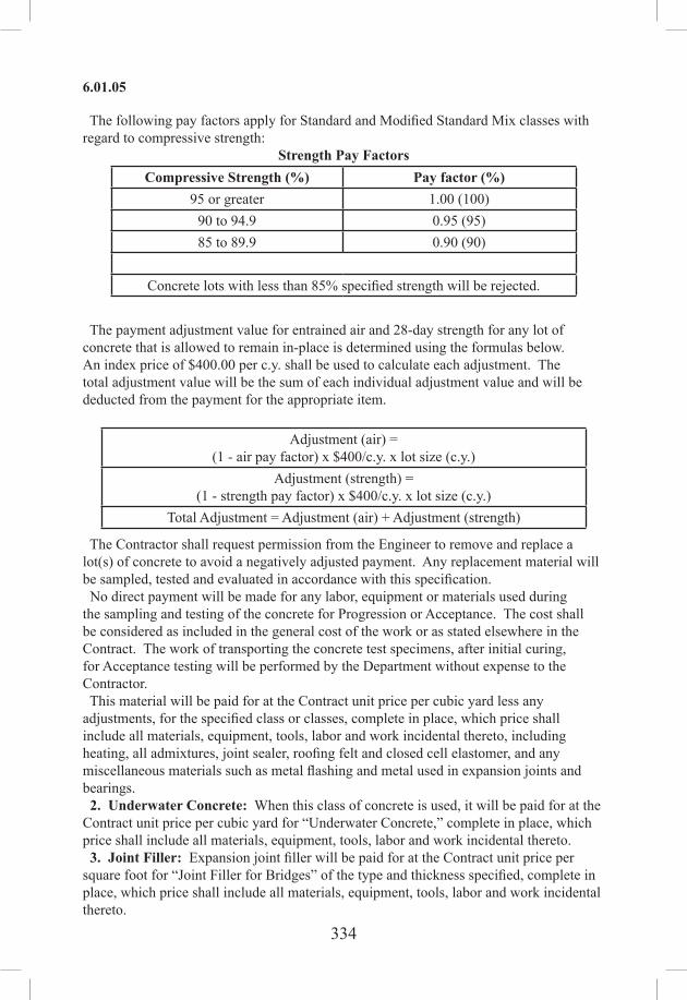
334
6.01.05
The following pay factors apply for Standard and Modified Standard Mix classes with regard to compressive strength:
Strength Pay FactorsCompressive Strength (%) Pay factor (%)
95 or greater 1.00 (100)90 to 94.9 0.95 (95)85 to 89.9 0.90 (90)
Concrete lots with less than 85% specified strength will be rejected.
The payment adjustment value for entrained air and 28-day strength for any lot of concrete that is allowed to remain in-place is determined using the formulas below. An index price of $400.00 per c.y. shall be used to calculate each adjustment. The total adjustment value will be the sum of each individual adjustment value and will be deducted from the payment for the appropriate item.
Adjustment (air) =(1 - air pay factor) x $400/c.y. x lot size (c.y.)
Adjustment (strength) =(1 - strength pay factor) x $400/c.y. x lot size (c.y.)
Total Adjustment = Adjustment (air) + Adjustment (strength)
The Contractor shall request permission from the Engineer to remove and replace a lot(s) of concrete to avoid a negatively adjusted payment. Any replacement material will be sampled, tested and evaluated in accordance with this specification. No direct payment will be made for any labor, equipment or materials used during the sampling and testing of the concrete for Progression or Acceptance. The cost shall be considered as included in the general cost of the work or as stated elsewhere in the Contract. The work of transporting the concrete test specimens, after initial curing, for Acceptance testing will be performed by the Department without expense to the Contractor. This material will be paid for at the Contract unit price per cubic yard less any adjustments, for the specified class or classes, complete in place, which price shall include all materials, equipment, tools, labor and work incidental thereto, including heating, all admixtures, joint sealer, roofing felt and closed cell elastomer, and any miscellaneous materials such as metal flashing and metal used in expansion joints and bearings. 2. Underwater Concrete: When this class of concrete is used, it will be paid for at the Contract unit price per cubic yard for “Underwater Concrete,” complete in place, which price shall include all materials, equipment, tools, labor and work incidental thereto. 3. Joint Filler: Expansion joint filler will be paid for at the Contract unit price per square foot for “Joint Filler for Bridges” of the type and thickness specified, complete in place, which price shall include all materials, equipment, tools, labor and work incidental thereto.

335
6.02.03
Pay Item Pay UnitClass “_” Concrete c.y.Underwater Concrete c.y.(Thickness and Type) Joint Filler for Bridges s.f.
SECTION 6.02REINFORCING STEEL
6.02.01—Description: Work under this item shall consist of furnishing and placing reinforcing steel and splicing materials, of the type and size designated, as shown on the plans, as directed by the Engineer and in accordance with these specifications.
6.02.02—Materials: The materials for this work shall meet the requirements of Article M.06.01.
6.02.03—Construction Methods: 1. Shop Drawings: Prior to fabricating any materials, the Contractor shall submit shop drawings of the reinforcing steel and splicing materials, with material lists, material designations, placement diagrams, bending diagrams and manufacturer’s literature for mechanical connections, for review and approval, in accordance with Article 1.05.02. Any expenses incidental to the revision of materials furnished in accordance with shop drawing and order lists to make them comply with the requirements of the plans, specifications or special provisions shall be borne by the Contractor. 2. Fabrication: (a) Cutting and Bending: Bar reinforcement shall be cut and bent to the shapes shown on the plans. Fabrication tolerances shall be in accordance with the requirements of ACI 315. All bars shall be bent cold, unless otherwise permitted. Coated bars shall not be field cut, unless permitted by the Engineer. If allowed, field cutting of coated bars shall be performed using hydraulic-powered cutters or friction cutting tools to minimize coating damage and field touch‑up. Flame cutting of coated bars will not be permitted. Field cut coated bars shall be repaired immediately. Bars partially embedded in concrete shall not be field bent, except as shown on the plans or permitted by the Engineer. (b) Hooks and Bend Dimensions: The dimensions of hooks and the diameters of bends measured on the inside of the bar shall be as shown on the plans. When the dimensions of hooks or the diameter of bends are not shown, they shall be in accordance with the ACI 318, “Building Code Requirements for Reinforced Concrete” as amended by ASTM A767 for galvanized bars.(c)Identification:Bar reinforcement shall be shipped in standard bundles, tagged and marked in accordance with the CRSI “Manual of Standard Practice.” 3. Handling, Storing and Surface Condition of Reinforcement: Steel reinforcement shall be stored above the surface of the ground on platforms, skids, or other supports and shall be protected as far as practical from mechanical injury and surface deterioration caused by exposure to conditions producing rust. Epoxy-coated and galvanized reinforcing steel shall be handled and stored by methods that will not damage the coating. All systems for handling coated reinforcement shall have adequately padded contact areas wherever possible. All bundling bands shall be padded and all bundles shall be lifted with a strong back, multiple supports, or platform bridge so as to prevent bar-to-bar abrasion from sags in the bar bundle. Bars or bundles

336
6.02.03
shall not be dropped or dragged. Coated reinforcing steel shall be transported and stored on wooden or padded supports. Epoxy-coated reinforcing steel, stored at the job Site, shall be protected by covering with opaque polyethylene or other suitable protective material. Provisions shall be made for adequate ventilation to prevent condensation under the covering. Since the epoxy coating is flammable, the epoxy coated reinforcing shall not be exposed to any fire or flame. Prior to placement of concrete, all reinforcement shall be free from dirt, loose rust or scale, mortar, paint, grease, oil, or other materials that would reduce bond. Reinforcement shall be free from injurious defects such as cracks and laminations. Bonded rust, surface seams, surface irregularities, or mill scale will not be cause for rejection, provided the minimum dimensions, cross section area, and tensile properties of a hand wire brushed specimen meet the physical requirements for the size and grade of steel specified. 4. Placing and Fastening: (a) General: Steel reinforcement shall be accurately placed as shown on the plans and firmly held in position during the placing and setting of concrete. Bars shall be tied at all intersections, except where the spacing is less than 12 in between intersections, alternate intersections shall be tied. Bars shall be tied at all intersections around the perimeter of each mat, regardless of spacing. Bundled bars shall be tied together at not more than 6-ft centers. Lap splices shall have a minimum of 2 ties or be tied 12 in apart for the length of the splice, whichever requires the greater number of ties. For epoxy-coated reinforcement, tie wires and metal clips shall be epoxy, plastic or nylon coated. For galvanized reinforcement, tie wires and metal clips shall be plastic coated or galvanized. With the exception of tie down bars, welding (tack welding) will not be permitted for assembly of reinforcement, unless shown on the plans. Tie down bars shall be placed as shown on the plans and a top longitudinal reinforcing bar tied to these bars. When welding coated bars an appropriate protective mask must be worn, safety equipment used and suitable ventilation provided. If wire fabric reinforcement is shipped in rolls, it shall be straightened into flat sheets before being placed. (b) Support Systems: Reinforcing steel shall be supported in its proper position by use of precast mortar blocks, wire bar supports, supplementary bars (tie-down bars), side form spacers or other approved devices. Such devices shall be sufficiently strong and properly placed at frequent intervals so as to maintain the cover between the reinforcing and the surface of the concrete. The reinforcing steel cover shall be no less than that shown on the plans and no greater than that shown plus 1/4 in. Platforms for the support of workers and equipment during concrete placement shall be supported directly on the forms and not on the reinforcing steel. (c) Precast Mortar Blocks: Precast mortar blocks shall have a compressive strength not less than that of the concrete in which they are to be embedded. The face of the blocks in contact with forms for exposed surfaces shall not exceed 2 in x 2 in and shall have a color and texture that will match the concrete surface. Precast mortar blocks shall not be used on exposed surfaces of precast concrete members. When used on vertical or sloping surfaces, such blocks shall have an embedded wire for securing the block to the reinforcing. When used in slabs, either such a tie wire or, when the weight of the

337
6.02.03
reinforcing is sufficient to firmly hold the blocks in place, a groove in the top of the block may be used. For epoxy-coated bars, such tie wires shall be epoxy, plastic or nylon coated. For galvanized bars, such tie wires shall be plastic coated or galvanized. (d) Wire Supports: Wire bar supports, such as ferrous metal chairs and bolsters, shall conform to industry practice as described in the CRSI “Manual of Standard Practice of the Concrete Reinforcing Steel Institute.” All bolsters or chairs which bear against the forms for exposed surfaces shall be equipped with snug fitting, high density, polyethylene tips which provide 1/2-in minimum clearance between the metal and any exposed surface. For epoxy-coated reinforcement, all wire bar supports and bar clips shall be epoxy or plastic coated. For galvanized reinforcement, chair and bar supports shall be hot-dip galvanized, after fabrication, in accordance with ASTM A123. The maximum spacing of slab bolster rows and high chair rows for concrete deck slabs shall be 4 ft unless otherwise directed by the Engineer. (e) Repair of Coated Reinforcing Steel: Epoxy-coated Reinforcing Steel - In addition to the requirements of ASTM D3963, all damage (i.e., scratches, nicks, cracks) to the epoxy coating of the bar reinforcement, visible to the unaided eye with corrective vision, caused during shipment, storage or placement shall be repaired by the Contractor at the Project Site with approved patching material. Ends of bars that have been sheared, saw cut or cut by other means shall be coated with approved patching material. The areas on the bars and tie down bars damaged by welding shall be repaired with approved patching material. Patching of damaged areas shall be performed in accordance with the patching material manufacturer’s recommendations. Any singular damaged surface area (prior to repair with approved patching material), shall not exceed 2% of the total surface area of the bar. The total bar surface area covered by patching material shall not exceed 5% of the total surface area of the bar. Should either of these limits be exceeded the bar shall be removed from the work and replaced with an acceptable bar. All patching material shall be fully cured prior to placing concrete. The patching material shall be compatible with the epoxy coating, inert in concrete, and suitable for repairs in the field. The patching material shall be prequalified, as required for the coating material, and shall be either identified on the container as meeting the requirements of Annex A1 of ASTM D3963 or shall be accompanied by a Materials Certificate certifying that the material meets the requirements of said Annex A1. Galvanized Reinforcing Steel - All damage (i.e. scratches, nicks, cracks) to the galvanized coating on bar reinforcement, visible to the unaided eye with corrective vision, caused during shipment, storage or placement shall be repaired by the Contractor at the job Site in accordance with ASTM A780, Annex A2 - “Repair using Zinc-Rich Paints.” Ends of bars that have been sheared, saw cut or cut by other means shall be coated with zinc-rich paint. The area on the bars and tie down bars damaged by welding shall be repaired with zinc-rich paint. Field coating of damaged areas shall be performed in accordance with the zinc-rich paint manufacturer’s recommendations. The zinc‑rich paint shall be as specified in FS TT‑P‑641, Type 1 and shall be brush applied to achieve a dry film thickness of 3 to 6 mils. All touchup paint shall be fully cured prior to placing concrete. 5. Splicing of Bars: (a) General: All reinforcement shall be furnished in the full lengths indicated on the
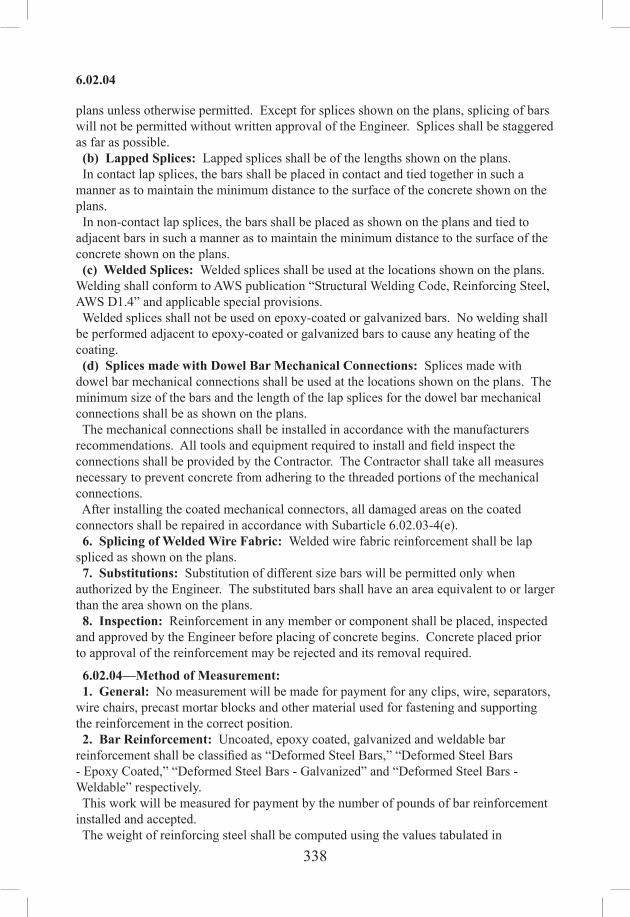
338
6.02.04
plans unless otherwise permitted. Except for splices shown on the plans, splicing of bars will not be permitted without written approval of the Engineer. Splices shall be staggered as far as possible. (b) Lapped Splices: Lapped splices shall be of the lengths shown on the plans. In contact lap splices, the bars shall be placed in contact and tied together in such a manner as to maintain the minimum distance to the surface of the concrete shown on the plans. In non-contact lap splices, the bars shall be placed as shown on the plans and tied to adjacent bars in such a manner as to maintain the minimum distance to the surface of the concrete shown on the plans. (c) Welded Splices: Welded splices shall be used at the locations shown on the plans. Welding shall conform to AWS publication “Structural Welding Code, Reinforcing Steel, AWS D1.4” and applicable special provisions. Welded splices shall not be used on epoxy-coated or galvanized bars. No welding shall be performed adjacent to epoxy-coated or galvanized bars to cause any heating of the coating. (d) Splices made with Dowel Bar Mechanical Connections: Splices made with dowel bar mechanical connections shall be used at the locations shown on the plans. The minimum size of the bars and the length of the lap splices for the dowel bar mechanical connections shall be as shown on the plans. The mechanical connections shall be installed in accordance with the manufacturers recommendations. All tools and equipment required to install and field inspect the connections shall be provided by the Contractor. The Contractor shall take all measures necessary to prevent concrete from adhering to the threaded portions of the mechanical connections. After installing the coated mechanical connectors, all damaged areas on the coated connectors shall be repaired in accordance with Subarticle 6.02.03-4(e). 6. Splicing of Welded Wire Fabric: Welded wire fabric reinforcement shall be lap spliced as shown on the plans. 7. Substitutions: Substitution of different size bars will be permitted only when authorized by the Engineer. The substituted bars shall have an area equivalent to or larger than the area shown on the plans. 8. Inspection: Reinforcement in any member or component shall be placed, inspected and approved by the Engineer before placing of concrete begins. Concrete placed prior to approval of the reinforcement may be rejected and its removal required.
6.02.04—Method of Measurement: 1. General: No measurement will be made for payment for any clips, wire, separators, wire chairs, precast mortar blocks and other material used for fastening and supporting the reinforcement in the correct position. 2. Bar Reinforcement: Uncoated, epoxy coated, galvanized and weldable bar reinforcement shall be classified as “Deformed Steel Bars,” “Deformed Steel Bars - Epoxy Coated,” “Deformed Steel Bars - Galvanized” and “Deformed Steel Bars - Weldable” respectively. This work will be measured for payment by the number of pounds of bar reinforcement installed and accepted. The weight of reinforcing steel shall be computed using the values tabulated in

339
6.02.05
Subarticle M.06.01-2. No allowance shall be made for the weight of the epoxy or galvanized coatings. Tie down bars will not be measured for payment. If short bars are used when full length bars might reasonably be required, only the amount which would be obtained if full length bars were used will be measured for payment. No allowance will be made for lap splices not contemplated by the plans unless approved by the Engineer. If bars are substituted upon the Contractor’s request and as a result more reinforcing steel is used than specified, only the amount specified will be included for payment. 3. Welded Wire Fabric: This work will be measured for payment by the number of pounds of welded wire fabric installed and accepted. The weight of welded wire fabric will be computed from the values published in the CRSI “Manual of Standard Practice.” 4. Dowel Bar Mechanical Connections: Uncoated, epoxy coated and galvanized dowel bar mechanical connections shall be classified as “Dowel Bar Splicer System,” “Dowel Bar Splicer System - Epoxy Coated” and “Dowel Bar Splicer System - Galvanized” respectively. This work will be measured for payment by the number of dowel bar mechanical connections installed and accepted.
6.02.05—Basis of Payment: Payment for this work will be made as follows: 1. Bar Reinforcement: This work will be paid for at the Contract unit price per pound for “Deformed Steel Bars,” “Deformed Steel Bars - Epoxy Coated,” “Deformed Steel Bars - Galvanized” or “Deformed Steel Bars - Weldable” complete in place and accepted, including shop drawings, furnishing, fabricating and placing reinforcing steel, welding splices and all materials, equipment, tools, labor and work incidental thereto. 2. Welded Wire Fabric: This work will be paid for at the Contract unit price per pound for “Welded Wire Fabric,” complete in place and accepted, including shop drawings, furnishing, fabricating and placing welded wire fabric and all materials, equipment, tools, labor and work incidental thereto. 3. Dowel Bar Mechanical Connections: This work will be paid for at the Contract unit price each for “Dowel Bar Splicer System,” “Dowel Bar Splicer System - Epoxy Coated” or “Dowel Bar Splicer System - Galvanized” complete in place and accepted, including shop drawings, furnishing, fabricating and placing dowel bar mechanical connections and all materials, equipment, tools, labor and work incidental thereto.
Pay Item Pay UnitDeformed Steel Bars lb.Deformed Steel Bars - Epoxy Coated lb.Deformed Steel Bars - Galvanized lb.Deformed Steel Bars - Weldable lb.Welded Wire Fabric lb.Dowel Bar Splicer System ea.Dowel Bar Splicer System - Epoxy Coated ea.Dowel Bar Splicer System - Galvanized ea.

340
6.03.01
SECTION 6.03STRUCTURAL STEEL
6.03.01—Description: Work under this item shall consist of furnishing, fabricating, transporting, storing, handling and erecting of structural steel of the type and size designated, as shown on the plans, as directed by the Engineer and in accordance with these specifications. All work, except as stated in the following paragraph, shall meet the requirements of the AASHTO LRFD Bridge Construction Specifications and the ANSI/AASHTO/AWS D1.5 – Bridge Welding Code. All work subject to railroad loading shall meet the requirements of AREMA and the ANSI/AASHTO/AWS D1.5 – Bridge Welding Code.
6.03.02—Materials: The materials for this work shall meet the requirements of Section M.06. Materials for this work shall be stored off the ground before, during, and after fabrication. It shall be kept free from dirt, grease and other contaminants and shall be reasonably protected from corrosion. In addition, weathering steel shall be stored as to allow free drainage and promote the development of the oxide coating and a uniform appearance.
6.03.03—Construction Methods:1.Pre-qualification: (a) Fabricators producing material for Department projects under this item are required to have as a minimum, an active AISC Certification for Simple Steel Bridges. For fabrication of material for use on bridges other than unspliced rolled beam bridges, AISC Major Steel Bridge Certification is required. If so noted on the plans, additional AISC endorsement for fabrication of fracture critical members is also required. (b) Field Welders: Prior to working on material for Department projects under this specification, all field welders, field welding operators, and field tackers must possess a valid welder certification card issued by the Department’s Division of Materials Testing. If such person has not been engaged in welding operations on a Department project or project acceptable to the Department within a period of 6 months, or cannot produce an approved welding certificate dated within the previous 12 months from a welding agency acceptable to the Engineer, the field welder shall be required to re‑qualify through examination. The Engineer may require requalification of anyone whose quality of work is in question. 2. Submittals: (a) Shop Drawings: Prior to any fabrication, the Contractor shall submit shop drawings in accordance with Article 1.05.02 to the Engineer for review. Shop drawings shall include a cambering procedure and diagram. In the case of trusses, the Contractor is responsible for calculation of the camber (lengthening and shortening) of all truss members. (b) Shop Schedule: The Contractor shall submit a detailed shop fabrication schedule to the Engineer for review within 30 days of the Notice to Proceed unless otherwise agreed to by the Engineer. At a minimum the schedule shall include the start date, milestone dates, and completion date. Any significant changes shall be brought to the attention of the Engineer immediately.

341
6.03.03
(c) Welding Procedures: Prior to start of fabrication, all welding procedures shall be submitted to the Engineer for review. (d) Working Drawings for Falsework and Erection of Structural Steel: Prior to erecting any steel fabricated under this specification, the Contractor shall submit drawings and supporting calculations, including erection stresses, in accordance with Article1.05.02, to the Engineer. The design of temporary supports and falsework shall be as specified in the AASHTO Specifications, the AASHTO Guide Design Specifications for Bridge Temporary Works or any other standard acceptable to the Engineer. Falsework shall be of sufficient rigidity and strength to safely support all loads imposed and to produce in the finished structure the lines and grades indicated in the Contract. The working drawings submittal shall include at a minimum: 1. Title block with Contract number, Project identification number (PIN), town, and
structure number and name. 2. Plan of the work area showing support structures, roads, railroad tracks, Federal
and State regulated areas as depicted on the plans, utilities or any other information relative to erection.
3. A detailed narrative describing the erection sequence for main members and secondary members (cross frames, diaphragms, lateral bracing, portals, etc.), noting use of holding cranes or temporary supports, falsework, or bents.
4. Delivery location of each girder. 5. Location of each crane for each pick. 6. Capacity chart for each crane and boom length used in the work. 7. The capacity of the crane and of all lifting and connecting devices shall be adequate
for the total pick load including spreaders and other materials. In the area of railroads and navigable waterways, the capacity shall be as required by Amtrak, Metro North, U.S. Coast Guard or other regulatory authorities. No picks shall be allowed over vehicular or pedestrian traffic unless otherwise noted on the plans or permitted by the Engineer.
8. Pick point location(s) on each member. 9. Lifting weight of each member including clamps, spreader beams, etc. 10. Lift and setting radius for each pick (or maximum lift radius). 11. Description of lifting devices or other connecting equipment. 12. Girder tie-down details or other method of stabilizing erected girders. 13. Bolting requirements, including the minimum number of bolts and erection pins
required to stabilize members during the erection sequence. 14. Blocking details for stabilizing members supported on expansion bearings and on
bearings that do not limit movement in the transverse direction. 15. The method and location for temporary supports for field spliced or curved girders,
including shoring, false work, holding cranes, guys, etc. The Engineer will review, but not approve details of temporary supports. The design, erection, and stability of these supports shall be the sole responsibility of the Contractor.
16. Offsets necessary to adjust expansion bearings during erection to provide for temperature variance and dead load rotation.
The following notes shall be placed on the Erection Drawings: 1. Cranes shall be operated in accordance with the Connecticut Department of Public
Safety regulations.

342
6.03.03
2. The Contractor shall be responsible for verifying the weight of each lift and for insuring the stability of each member during all phases of erection.
3. Members shall be subject to only light drifting to align holes. Any drifting that results in distortion of the member or damage to the holes will be cause for rejection of the member.
4. Field reaming of holes shall not be performed unless required by the Contract drawings or approved by the Engineer.
The Contractor shall submit these documents to the Engineer at least 60 calendar days in advance of their proposed use. If the proposed method of erection requires additional members or modifications to the existing members of the structure, such additions and modifications shall be made by the Contractor at no expense to the State. 3. Shop Fabrication: Unless otherwise shown on the plans or indicated in the Special Provisions, Structural Steel shall be fabricated in accordance with the AASHTO LRFD Bridge Construction Specifications, amended as follows:(a)Notification: The Contractor shall submit written notification to both the Engineer and the Division Chief (OOC) not less than 30 calendar days prior to start of fabrication. No material shall be manufactured or worked in the shop before the Engineer has been so notified. The notification shall include the name and location of the fabrication shop where the work will be done so that arrangements can be made for an audit of the facility and the assignment of a Department Quality Assurance inspector. (b) Camber: All members shall be cambered prior to heat curving and painting. Rolled beams shall be heat cambered by methods approved by the Engineer. Plate girders shall be cambered by cutting the web to the prescribed shape with allowances for shrinkage due to cutting, welding, and heat curving. The fabricator is responsible to determine what allowances should be made. Rolled, plate-rolled, or fabricated sections shall be cambered to the total amount shown on the plans and within the camber deviation tolerances permitted for welded beams and girders, as indicated in the ANSI/AASHTO/AWS D1.5 Bridge Welding Code. The Contractor must submit to the Engineer for approval, a plan for corrective action if the actual camber is not within tolerance. (c) Welding: Unless otherwise indicated in the Contract, all work shall be performed in accordance with ANSI/AASHTO/AWS D1.5 – Bridge Welding Code. (d) Preassembly of Field Connections: Field connections of main members of continuous beams, plate girders, bents, towers, rigid frames, trusses and arches shall be preassembled prior to erection as necessary to verify the geometry of the completed structure or unit and to verify or prepare field splices. The Contractor shall propose an appropriate method of preassembly for review and comment by the Engineer. The method and details of preassembly shall be consistent with the erection procedures shown on the working drawings and camber diagrams. As a minimum, the preassembly procedure shall consist of assembling 3 contiguous panels accurately adjusted for line and camber. Successive assemblies shall consist of at least 1 section or panel of the previous assembly plus 2 or more sections or panels added at the advancing end. In the case of structures longer than 150 ft, each assembly shall not be less than 150 ft long regardless of the length of individual continuous panels or section. All falsework, tools, machinery and appliances, including drift pins and bolts necessary for the expeditious handling of the work shall be provided by the Contractor at no cost to the State. (e) Inspection: The Contractor shall furnish facilities for the inspection of material and

343
6.03.03
workmanship in the shop by the Engineer. The Engineer and any representatives of the Engineer shall be allowed free access to the necessary parts of the premises. The Engineer will provide Quality Assurance (QA) inspection at the fabrication shop to assure that all applicable Quality Control plans and inspections are adequately adhered to and maintained by the Contractor during all phases of the fabrication. A thorough inspection of a random selection of elements at the fabrication shop may serve as the basis of this assurance. Prior to shipment to the Project, each individual piece of structural steel shall be stamped or marked in a clear and permanent fashion by a representative of the fabricators’ Quality Control (QC) Department to indicate complete final inspection by the fabricator and conformance to the Project specifications for that piece. The stamp or mark must be dated. A Materials Certificate in accordance with Article 1.06.07 may be used in lieu of individual stamps or markings, for all material in a single shipment. The Materials Certificate must list each piece within the shipment and accompany the shipment to the Project Site. Following the final inspection by the fabricator’s QC personnel, the Engineer may select pieces of structural steel for re-inspection by the Department’s QA inspector. Should non‑conforming pieces be identified, all similar pieces must be re‑inspected by the fabricator and repair procedure(s) submitted to the Engineer for approval. Repairs will be made at the Contractor’s expense. The pieces selected for re-inspection and found to be in conformance, or adequately repaired pieces, may be stamped or marked by the QA inspector. Such markings indicate the Engineer takes no exception to the pieces being sent to the Project Site. Such marking does not indicate acceptance or approval of the material by the Engineer. Following delivery to the Project Site, the Engineer will perform a visual inspection of all material to verify shipping documents, fabricator markings, and that there was no damage to the material or coatings during transportation and handling. The Engineer is not responsible for approving or accepting any fabricated materials prior to final erection and assembly at the Project Site. (f) Nondestructive Testing: All nondestructive testing of structural steel and welding shall be performed as designated in the plans and specifications. Such testing shall be performed by personnel approved by the Engineer. Personnel performing Radiographic, Ultrasonic or Magnetic Particle testing shall be certified as a NDT Level II technician in accordance with the American Society for Non Destructive Testing (ASNT), Recommended Practice SNT-TC-1A. Nondestructive testing shall be performed in accordance with the procedures and standards set forth in the AASHTO/AWS D1.5, Bridge Welding Code. The Department reserves the right to perform additional testing as determined by the Engineer. All nondestructive testing shall be witnessed by an authorized representative of the Department. Certified reports of all tests shall be submitted to the Division of Materials Testing for examination. Each certified test report shall identify the structure, member, and location of weld or welds tested. Each report shall also list the length and location of any defective welds and include information on the corrective action taken and results of all retests of repaired welds. Should the Engineer require nondestructive testing on welds not designated in the Contract, the cost of such inspection shall be borne by the Contractor if the testing

344
6.03.03
indicates that any weld is defective. If the testing indicates the weld to be satisfactory, the actual cost of such inspection will be paid by the Department. (g) Marking: Each member shall be identified with an erection mark corresponding with the member identification mark on the approved shop drawings. Identification marks shall be impressed into the member with a low stress stamp in a location in accordance with standard industry practice. (h) Shipping, Handling, Storage and Receiving: The Contractor shall make all arrangements necessary to properly load, transport, unload, handle and store all material. The Contractor shall furnish to the Engineer copies of all shipping statements. The weight of the individual members shall be shown on the statements. Members having a weight of more than 3 tons shall have the weight marked thereon. All material shall be unloaded promptly upon delivery. The Contractor shall be responsible for any demurrage charges. Damage to any material during transportation, improper storage, faulty erection, or undocumented fabrication errors may be cause for rejection of said material at the Project Site. Top lateral bracing shall be installed in tub girders prior to shipping and erection of the field pieces. All costs associated with any corrective action will be borne by the Contractor. 4. Field Erection: A meeting shall be held on Site prior to any erection of structural steel. The Contractor shall name the person responsible for the steel erection work and provide copies of all crane operator licenses. Proposed equipment, rigging, timetable and methods shall be proposed at this meeting. (a) Falsework: Any temporary work shall be constructed in accordance with the working drawings. The Contractor shall verify that the quality of materials and work employed are consistent with their design. All girders shall be stabilized with falsework, temporary braces, or holding cranes until a sufficient number of adjacent girders are erected with all diaphragms and cross frames connected to provide necessary lateral support as shown in the erecting diagrams. Adjustment shall be provided in the falsework and other temporary supports so that the temporary elevation of the structural steel provided by the falsework is consistent with the deflections that will occur as the structure is completed. The elevation of falsework shall be such as to support the girders at the cambered no-load elevation. Unloading of temporary supports shall be performed such that all temporary supports at each cross section are unloaded uniformly. Unless specifically permitted by the Engineer, welding of falsework support brackets to structural steel is not allowed. Unless erected by the cantilever method, truss spans shall be erected on blocking. The blocking shall be left in place until the tension chord splices are fully bolted and all other truss connections pinned and bolted and the proper geometric shape is achieved. (b) Anchorages: Anchor bolts and similar materials which are to be placed during the erection of the structural steel shall be carefully and accurately set to the requirements of Article 6.01.03. (c) Bearings: Bearing plates shall have a full and uniform bearing upon the substructure masonry. Bearing plates shall be placed upon bearing areas which are finished according to the requirements of Article 6.01.03. Prefabricated pads meeting the requirements of Article M.12.01 shall be installed, unless specifically noted otherwise in the Contract plans. Each piece shall be the same size as the bearing plate it is to support and the holes to

345
6.03.03
accommodate the anchor bolts shall be clearly and accurately punched before setting the pad in place. In placing expansion bearings, due consideration shall be given to the temperature at the time of erection and stage construction requirements. The nuts of anchor bolts at expansion bearings shall be adjusted to permit the free movement of the span. (d) Field Assembly: Members and components shall be accurately assembled as shown on the plans and any match marks shall be followed. The material shall be carefully handled so that no components will be bent, broken or otherwise damaged. Hammering which will injure or distort the members is not permitted. Bearing surfaces and surfaces to be in permanent contact shall be cleaned before the members are assembled. Cylindrical erection pins shall be 1/32 in larger than the nominal diameter of the holes. Splices and field connections of main stress carrying members shall be made with a minimum of 50% of the holes filled and tightened with high strength bolts before the lifting system is released. The bolts shall be installed uniformly throughout the connection. Lateral stability must be maintained until the deck is placed. The Contractor shall ensure that girders are stable throughout the erection process. The stage of completeness of the bolted connections shall be considered when evaluating the strength and stability of the steel during erection. For Closed Box and Tub Girders the Contractor shall ensure that the cross-section shape of each box is maintained during erection. Top lateral bracing shall be installed in tub girders prior to shipping and erection of the field pieces. (e) Welded Connections: Unless otherwise shown on the plans or indicated by the special provisions, welding of structural steel shall be done in accordance with ANSI/AASHTO/AWS D1.5 Bridge Welding Code. The Contractor’s welding and inspection procedures for each type of field weld and field tacking must be submitted to the Engineer on the form designated by the Department. All procedures must be approved by the Division of Materials Testing prior to any work and must be adhered to at all times. Quality control is the responsibility of the Contractor. The Contractor must provide an AWS Certified Welding Inspector (CWI) in accordance with AWS D1.5. The CWI must be qualified and certified in accordance with the provisions of AWS QC1, Standard for Qualification and Certification of Welding Inspectors. The CWI shall make visual inspection of all welds. The Contractor will perform magnetic particle inspection, ultrasonic testing inspection, or radiographic testing inspection of field welds when required on the plans or special provisions. Each test may be witnessed by an authorized representative of the Engineer. Welds or sections of welds containing imperfections determined to be unacceptable by either the CWI or the Engineer shall be removed and re-welded by the Contractor at their expense. Welds so removed and replaced shall be re-inspected by the CWI. All costs for re-inspection or testing of such welds shall be borne by the Contractor. (f) High Strength Bolted Connections: The assembly of structural connections using ASTM A325 or ASTM A490 high-strength bolts shall be installed so as to develop the minimum required bolt tension specified in Table A. The Manufacturer’s certified test report; including the rotational capacity test results must accompany the fastener assemblies. Fastener Assemblies delivered without the certified reports will be rejected.

346
6.03.03
TABLEA:MinimumBoltTensioninkips*Bolt Size (Inches) ASTM A325 ASTM A490
5/8 19 243/4 28 357/8 39 491 51 64
1 1/8 56 801 1/4 71 1021 3/8 85 1211 1/2 103 148
*Equal to 70% of specified minimum tensile strength of bolts (as specified in ASTM Specifications for tests of full‑size A325 and A490 bolts with UNC threads, loaded in axial tension) rounded to the nearest kip.
Bolts, nuts and washers from each rotational-capacity lot shall be shipped in the same container. If there is a single production lot number for each size of nut and washer, the nuts and washers may be shipped in separate containers, each permanently marked with the rotational‑capacity lot number such that identification will be possible at any stage prior to installation. Assemblies of bolts, nuts and washers shall be installed from the same rotational-capacity lot. Pins, small parts and packages of bolts, washers, and nuts shall be shipped in boxes, crates, kegs, or barrels. A list and description of the contained materials shall be plainly marked on the outside of each shipping container. Bolted Parts: All material within the grip of the bolt shall be steel; there shall be no compressible material, such as gaskets or insulation, within the grip. Bolted steel shall fit solidly together after the bolts are tensioned. The length of the bolts shall be such that the end of the bolt will be flush with or outside of the face of the nut when properly installed. Surface Conditions: At the time of assembly, all connection surfaces, including surfaces adjacent to the bolt head and nut, shall be free of scale, except tight mill scale, and shall be free of dirt or other foreign material. Burrs that would prevent solid seating of the connected parts in the snug tight condition shall be removed. Paint is only permitted on the faying surface, including slip critical connections, when shown on the plans. The faying surfaces of slip‑critical connections shall be as specified in the following paragraphs, as applicable: 1. Connections specified to have un‑coated faying surfaces: any paint, including any
inadvertent over spray, shall be excluded from areas closer than 1 bolt diameter, but not less than 1.0 in, from the edge of any hole and all areas within the bolt pattern.
2. Connections specified to have painted faying surfaces shall be blast cleaned and coated in accordance with the Contract, and shall not be assembled until the coating system has been properly cured.
3. Connections specified to have galvanized faying surfaces shall be hot‑dip galvanized in accordance with ASTM A123, and shall subsequently be roughened by means of hand wire brushing. Power wire brushing is not permitted.
Installation: At the pre-erection meeting, the Contractor shall inform the Engineer of its planned method of tensioning high strength bolts

347
6.03.03
Acceptable methods are: 1. Turn-of-Nut , 2. Calibrated Wrench or 3. Direct Tension Indicator Fastener Assemblies: A “fastener assembly” is defined as a bolt, a nut, and a washer. Only complete fastener assemblies of appropriately assigned lot numbers shall be installed. Fastener assemblies shall be stored in an area protected from dirt and moisture. Only as many fastener assemblies as are anticipated to be installed and tensioned during a work shift shall be taken from protected storage. Fastener assemblies not used shall be returned to protected storage at the end of the shift. Prior to installation, fastener assemblies shall not be cleaned of lubricant. Fastener assemblies which accumulate rust or dirt resulting from site conditions shall be cleaned, relubricated and tested for rotational-capacity prior to installation. All galvanized nuts shall be lubricated with a lubricant containing a visible dye. Plain bolts must be oily to the touch when delivered and installed. Lubricant shall be removed prior to painting. All bolts shall have a hardened washer under the turned element (nut or bolt head). All hardened washers shall meet the requirements of ASTM F436. Where necessary, washers may be clipped on 1 side to a point not closer than 7/8 of the bolt diameter from the center of the washer. Circular and beveled washers, when used adjacent to direct tension indicator washers shall not be clipped. Direct tension indicator washers shall not be clipped. Bolt Tension Measuring Device: The Contractor shall provide a calibrated bolt tension measuring device (a Skidmore-Wilhelm calibrator (Skidmore) or other acceptable bolt tension indicating device) at all times when, and at all locations where high-strength fasteners are being installed and tensioned. The tension measuring device (Skidmore) shall be calibrated by an approved testing agency at least annually. The Skidmore shall be used to perform the rotational-capacity test of the fastener assemblies. The Skidmore will also be used to substantiate
(1) the suitability of the fastener assembly to satisfy the requirements of Table A, including lubrication as required,
(2) calibration of the installation wrenches, if applicable, and (3) the understanding and proper use by the Contractor of the selected method of
tensioning to be used Complete fastener assemblies shall be installed in properly aligned holes and then tensioned by the Turn-of-Nut, Calibrated Wrench or Direct Tension Indicator method to the minimum tension specified in Table A. Tensioning may be done by turning the bolt while the nut is prevented from rotating when it is impractical to turn the nut. Impact wrenches, if used, shall be of adequate capacity and sufficiently supplied with air to perform the required tensioning of each bolt in approximately 10 seconds. Bolts shall be installed in all holes of the connection and the connection brought to a snug condition. Snug is defined as having all the plies of the connection in firm contact. Snugging shall progress systematically from the most rigid part of the connection to the free edges. The bolts of the connection shall then be tightened in a similar manner as
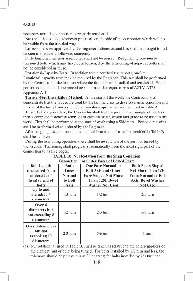
348
6.03.03
necessary until the connection is properly tensioned. Nuts shall be located, whenever practical, on the side of the connection which will not be visible from the traveled way. Unless otherwise approved by the Engineer fastener assemblies shall be brought to full tension immediately following snugging. Fully tensioned fastener assemblies shall not be reused. Retightening previously tensioned bolts which may have been loosened by the tensioning of adjacent bolts shall not be considered as reuse. Rotational‑Capacity Tests: In addition to the certified test reports, on‑Site Rotational-capacity tests may be required by the Engineer. This test shall be performed by the Contractor at the location where the fasteners are installed and tensioned. When performed in the field, the procedure shall meet the requirements of ASTM A325 Appendix A-1. Turn-of-Nut Installation Method: At the start of the work, the Contractor shall demonstrate that the procedure used by the bolting crew to develop a snug condition and to control the turns from a snug condition develops the tension required in Table A. To verify their procedure, the Contractor shall test a representative sample of not less than 3 complete fastener assemblies of each diameter, length and grade to be used in the work. This shall be performed at the start of work using a Skidmore. Periodic retesting shall be performed when ordered by the Engineer. After snugging the connection, the applicable amount of rotation specified in Table B shall be achieved. During the tensioning operation there shall be no rotation of the part not turned by the wrench. Tensioning shall progress systematically from the most rigid part of the connection to its free edges.
TABLE B: Nut Rotation from the Snug ConditionGeometrya,b,c of Outer Faces of Bolted Parts
Bolt Length(measured from
underside of head to end of
bolt)
Both Faces
Normal to Bolt Axis
One Face Normal to Bolt Axis and Other
Face Sloped Not More Than 1:20, Bevel Washer Not Used
Both Faces Sloped Not More Than 1:20 From Normal to Bolt Axis, Bevel Washer
Not UsedUp to and
including 4 diameters
1/3 turn 1/2 turn 2/3 turn
Over 4 diameters but
not exceeding 8 diameters
1/2 turn 2/3 turn 5/6 turn
Over 8 diameters but not
exceeding 12 diameters
2/3 turn 5/6 turn 1 turn
(a) Nut rotation, as used in Table B, shall be taken as relative to the bolt, regardless of the element (nut or bolt) being turned. For bolts installed by 1/2 turn and less, the tolerance should be plus or minus 30 degrees; for bolts installed by 2/3 turn and

349
6.03.03
more, the tolerance should be plus or minus 45 degrees. To determine the nut rotation for installation and inspection of the fasteners, the nut and the end of the bolt or the head of the bolt and the adjacent steel shall be match marked.
(b) The values, given in Table B, shall be applicable only connections in which all material within grip of the bolt is steel.
(c) No research work has been performed by the Research Council on Riveted and Bolted Structural Joints to establish the turn-of-nut procedure when bolt lengths exceed 12 diameters. For situations in which the bolt length, measured from the underside of the head to the end of the bolt, exceeds 12 diameters, the required rotation shall be determined by actual tests in a suitable tension device simulating the actual conditions.
Calibrated Wrench Installation Method: Calibrated wrench method may be used only when the installation wrenches are properly calibrated daily, or as determined by the Engineer. Standard torques determined from tables or from formulas which are assumed to relate torque to tension shall not be acceptable. The Contractor shall demonstrate to the Engineer periodically that all equipment and wrenches are providing a torque which has been calibrated to produce the minimum tension specified in Table A. The installation procedures shall be verified periodically, as determined by the Engineer, for each bolt diameter, length and grade using the fastener assemblies that are being installed in the work. This verification testing shall be accomplished in a Skidmore by tensioning 3 complete fastener assemblies of each diameter, length and grade from those being installed with a hardened washer under the element turned. When significant difference is noted in the surface condition of the bolts, threads, nuts or washers, as determined by the Engineer, wrenches shall be recalibrated. The Contractor shall verify during the installation of the assembled steel work that the wrench adjustment selected by the calibration does not produce a nut or bolt head rotation from snug greater than that permitted in Table B. If manual torque wrenches are used, nuts shall be turned in the tensioning direction when torque is measured. When calibrated wrenches are used to install and tension bolts in a connection, bolts shall be installed with hardened washers under the element turned to tension the bolts. Once the connection has been snugged, the bolts shall be tensioned using the calibrated wrench. Tensioning shall progress systematically from the most rigid part of the connection to its free edges. A calibrated torque wrench shall be used to “touch up” previously tensioned bolts which may have been relaxed as a result of the subsequent tensioning of adjacent bolts until all bolts are tensioned to the prescribed amount. Direct Tension Indicator Installation Method: When Direct Tension Indicators (DTIs) meeting the requirements of Section M.06 are used with high-strength bolts to indicate bolt tension, they shall be subjected to the verification testing described below and installed in accordance with the method specified below. Unless otherwise approved by the Engineer, the DTIs shall be installed under the head of the bolt and the nut turned to tension the bolt. The Manufacturer’s recommendations shall be followed for the proper orientation of the DTI and additional washers, if any, required for the correct use of the DTI. Installation of a DTI under the turned element may be permitted if a washer

350
6.03.03
is used to separate the turned element from the DTI. Verification: Verification testing shall be performed in a Skidmore. A special flat insert shall be used in place of the normal bolt head holding insert. Three (3) verification tests shall be required for each combination of fastener assembly rotational-capacity lot, DTI lot, and DTI position relative to the turned element (bolt head or nut) to be used on the Project. The fastener assembly shall be installed in the tension-measuring device with the DTI located in the same position as in the work. The element intended to be stationary (bolt or nut) shall be restrained from rotation. The verification tests shall be conducted in 2 stages. The bolt nut and DTI assembly shall be installed in a manner so that at least 3 and preferably not more than 5 threads are located between the bearing face of the nut and the bolt head. The bolt shall be tensioned first to the load equal to that listed in Table C under Verification Tension for the grade and diameter of the bolt. If an impact wrench is used, the tension developed using the impact wrench shall be no more than 2/3 of the required tension. Subsequently, a manual wrench shall be used to attain the required tension. The number of refusals of the 0.005 in tapered feeler gage in the spaces between the protrusions shall be recorded. The number of refusals for uncoated DTIs under the stationary or turned element, or coated DTIs under the stationary element, shall not exceed the number listed under Maximum Verification Refusals in Table C for the grade and diameter of bolt used. The maximum number of verification refusals for coated DTIs (galvanized, painted, or epoxy‑coated), when used under the turned element, shall be no more than the number of spaces on the DTI less one. The DTI lot shall be rejected if the number of refusals exceeds the values in the table or, for coated DTIs if the gage is refused in all spaces.
TABLE CBolt Dia. (in)
VerificationTension
MaximumVerification
Refusals
DTISpaces
MinimumInstallation
RefusalsA325 A490 A325 A490 A325 A490 A325 A490
5/8 20 25 1 2 4 5 2 33/4 29 37 2 2 5 6 3 37/8 41 51 2 2 5 6 3 31 54 67 2 3 6 7 3 4
1 1/8 59 84 2 3 6 7 3 41 1/4 75 107 3 3 7 8 4 41 3/8 89 127 3 3 7 8 4 41 1/2 108 155 3 4 8 9 4 5
After the number of refusals is recorded at the verification load, the bolt shall be further tensioned until the 0.005 in feeler gage is refused at all the spaces and a visible gap exists in at least 1 space. The load at this condition shall be recorded and the bolt removed from the tension-measuring device.The nut shall be able to be run down by hand for the complete thread length of the bolt

351
6.03.03
excluding thread run-out. If the nut cannot be run down for this thread length, the DTI lot shall be rejected unless the load recorded is less than 95% of the average load measured in the rotational capacity test of the fastener lot as specified previously in “Rotational‑Capacity Tests.” If the bolt is too short to be tested in the calibration device, the DTI lot shall be verified on a long bolt in a calibrator to determine the number of refusals at the verification tension listed in Table C. The number of refusals shall not exceed the values listed under Maximum Verification Refusals in Table C. Another DTI from the same lot shall then be verified with the short bolt in a convenient hole in the work. The bolt shall be tensioned until the 0.005-in. feeler gage is refused in all spaces and a visible gap exists in at least 1 space. The bolt shall then be removed from the tension-measuring device and the nut shall be able to be run down by hand for the complete thread length of the bolt excluding thread run-out. The DTI lot shall be rejected if the nut cannot be run down this thread length. Installation: Installation of fastener assemblies using DTIs shall be performed in 2 stages. The stationary element shall be held against rotation during each stage of the installation. The connection shall be first snugged with bolts installed in all holes of the connection and tensioned sufficiently to bring all the plies of the connection into firm contact. The number of spaces in which a 0.005 in feeler gage is refused in the DTI after snugging shall not exceed those listed under maximum verification refusals in Table C. If the number exceeds the values in the table, the fastener assembly shall be removed and another DTI installed and snugged. For uncoated DTIs used under a stationary or turned element and for coated DTIs used under a stationary element, the bolts shall be further tensioned until the number of refusals of the 0.005 in feeler gage shall be equal or greater than the number listed under Minimum Installation Refusals in Table C. If the bolt is tensioned so that no visible gap in any space remains, the bolt and DTI shall be removed and replaced by a new properly tensioned bolt and DTI. When coated DTIs (galvanized, painted or epoxy coated) are used under a turned element, the 0.005 in feeler gage shall be refused in all spaces.Inspection: The Contractor shall provide all the material, equipment, tools and labor necessary for the inspection of the bolted connections. Access to the bolted parts and fastener assemblies, both before and after the fasteners are installed and tensioned, shall be provided. The Contractor is responsible for Quality Control (QC). The Contractor shall review this specification with its Project personnel prior to performing the work. The Contractor shall verify the proper markings, surface conditions and storage of fastener assemblies. The Contractor shall inspect the faying surfaces of connections for compliance with the plans and specifications. The Contractor shall provide to the Engineer a copy of their written QC report for each shift of the calibration or verification testing specified. This report shall confirm that the selected procedure is properly used and that the fastener assemblies installed meet the tensions specified in Table A. The Contractor shall monitor the installation of fasteners in the work to assure that the selected procedure, as demonstrated in the initial testing to provide the specified tension, is routinely and properly applied. The Contractor, in the presence of the Engineer, shall inspect the tensioned bolts using

352
6.03.04
an inspection torque wrench, as defined below. If DTI devices are used, the appropriate feeler gauge will be used. Inspection tests shall be performed within 24 hours of bolt tensioning to prevent possible loss of lubrication or corrosion influence on tensioning torque. The inspection torque wrench shall be calibrated as follows: Three (3) bolts of the same grade, size, and condition as those under inspection shall be placed individually in a device calibrated to measure bolt tension. This calibration operation shall be done at least once each inspection day. There shall be a washer under the part turned in torqueing each bolt. In the calibrated device, each bolt shall be tightened by any convenient means to the specified tension. The inspection wrench shall then be applied to the tensioned bolt to determine the torque required to turn the nut or head 5degrees in the tightening direction. The average of the torque required for all 3 bolts shall be defined as the job‑inspection torque. Twenty‑five percent (25%), but a minimum of 2 each of the tensioned bolts shall be selected by the Engineer for inspection in each connection. (The Engineer may reduce the number of bolts tested at a connection to 10% based on the Contractor’s past performance and splice location.) The job-inspection torque shall then be applied to each selected assembly with the inspection torque wrench turned in the tightening direction. If all inspected bolt heads or nuts do not turn, the bolts in the connection shall be considered to be properly tensioned. If the torque turns 1 or more bolt heads or nuts, the job-inspection torque shall then be applied to all bolts in the connection or to the satisfaction of the Engineer. Any bolt whose head or nut turns shall be re-tensioned and re-inspected. The Contractor may, however, re-tension all the bolts in the connection with the inspection torque wrench and resubmit it for inspection, as long as the bolts are not over-tensioned or damaged by this action.(g)FieldCorrectionsandMisfits: Reaming of bolt holes during erection shall be permitted only with approval of the Engineer. No excessive forces shall be applied to any member to provide for proper alignment of the bolt holes. The correction of minor misfits involving minor amounts of reaming, cutting, grinding and chipping shall be considered a legitimate part of the erection. However, any error in the shop fabrication or deformation resulting from handling and transportation may be cause for rejection. The Contractor shall be responsible for all misfits, errors and damage and shall make the necessary corrections and replacements.
6.03.04—Method of Measurement: Payment under this item will be either at the Contract lump sum price per completed bridge structure or will be based on the net weight of metal in the fabricated structure, whichever measurement method appears on the bid proposal form. When payment is on a lump sum basis, the work, including anchor bolts, steel bearings and plates will not be measured for payment. Bearing plates welded to the girder are included in the price of the structural steel and bearing plates bonded to the bearings are included in the price of the bearing. When payment is based on the net weight of metal in the fabricated structure, it will be computed as described below. The weight of the metal works to be paid for under the item of structural steel will be computed on the basis of the net finished dimensions of the parts as shown on the shop drawings, deducting for copes, cuts, clips and all open holes, except bolt holes, and on the

353
6.05.03
following basis:1. The weights of rolled shapes will be computed on the basis of their nominal weights
per foot, as shown in the shop drawings or listed in handbooks. The weight of plates will be computed on the basis of the nominal weight for their width and thickness as shown on the shop drawings.
2. The weight of temporary erection bolts, shop and field paint, galvanization, boxes, crates and other containers used for shipping, and materials used for supporting members during transportation and erection, will not be included.
3. The weight of all high strength bolts, nuts, and washers will be included on the basis of the following weights:
Weight per 100 (in pounds)Nominal diameter of
H.S. bolt (inch)Bolthead, nut, 1 washer and
stickthrough (lb.)1/2 225/8 333/4 557/8 841 120
1 1/8 1691 1/4 216
4. The weight of weld metal will be computed on the basis of the theoretical volume from plan dimensions of the welds on the basis of the following weights:
SizeoffilletinInches
Weight of Weld inpounds per foot
3/16 0.081/4 0.145/16 0.223/8 0.301/2 0.555/8 0.803/4 1.107/8 1.501 2.00
5. The weight of steel shims, filler plates and anchor bolts will be measured for payment.
6.03.05—Basis of Payment: The structural steel, incorporated in the completed and accepted structure, will be paid for either at the Contract lump sum price for “Structural Steel (Site No. )” or at the Contract unit price per hundredweight for “Structural Steel,” whichever is indicated in the Contract. Payment for either method shall be for structural steel, complete in place, which price

354
6.05.01
shall include quality control, furnishing, fabricating, transporting, storing, erecting, welding, surface preparation and all materials including fastener assemblies, steel bearing assemblies and anchor bolts, equipment, tools and labor incidental thereto. The cost of the raw material is included in the lump sum payment for “Structural Steel (Site No. ).” All remaining work including, but not limited to, preparation of shop drawings, fabricating, transporting, storage and handling, erecting, surface preparation and all materials, equipment, tools and labor incidental thereto, will be paid for under the lump sum payment for “Structural Steel (Site No. ).” No direct payment will be made for setting anchor bolts, preparing bearing areas, furnishing and placing materials under bearings. No direct payment will be made for non-destructive testing as shown on the plans.
Pay Item Pay UnitStructural Steel (Site No. ) l.s.Structural Steel cwt.
SECTION 6.05MASONRY FACING
6.05.01—Description6.05.02—Materials6.05.03—Construction Methods6.05.04—Method of Measurement6.05.05—Basis of Payment
6.05.01—Description: This item shall consist of a surface course or facing of masonry of the hereinafter specified quality, applied to the exposed surfaces of the concrete structures as a protection or ornamentation. It shall be constructed to the dimensions indicated on the plans or as ordered and in accordance with these specifications.
6.05.02—Materials: The materials for this work shall meet the requirements of Article M.11.01 for masonry facing stone, Article M.11.04 for mortar and Article M.06.01 for metal dowels and ties.
6.05.03—Construction Methods: Each grade of masonry facing stone shall be constructed in the location and to the dimensions shown on the plans or as ordered and shall be built in conjunction with concrete backing. The backing shall not be placed until the masonry facing and any required dowels or ties have been properly placed. The work shall be carried on in successive layers or lifts as permitted by the Engineer. Care must be taken to prevent any movement of the masonry already in place while placing and compacting the concrete. When required by the Engineer, the facing stone shall be supported by such bracing and form work as may be necessary to prevent movement. All stone shall be set by competent and experienced masons. 1. Dressing Stone: All stones shall be dressed to the required size and shape before being laid and, except in the case of granite, shall be cut to lie on their natural beds. The bottom bed shall be the full size of the stone, and no stone shall have an overhanging top. In rock-faced work the exposed surface of any stone shall not present an excessively undercut contour adjacent to its bottom arris giving a top heavy, unstable appearance when laid. Beds and joints of dimensioned masonry stone, except for rock‑faced surface finish

355
6.05.03
stone, shall be fine finished a full 2 in from the pitch line of the face from which point the bottom bed may fall under the square 1 in per 12 in; the top bed 1 1/2 in per 12 in; and the joints 2 in per 12 in; but all beds must have a reasonable area of bearing spots back of the face. They shall be free from large depressions which might impair the stability of the work. On rock-faced stone, the beds shall be sawn or dressed full for at least the specified minimum width of the stone; beyond that the beds may fall under the square not in excess of 3 in per 12 in. The joints shall be cut full and square for at least 2 in back of the pitch lines from which point they may fall away not over 3 in per 12 in. Headers, if called for, shall have a back dimension not less than 2/3 of the corresponding face dimension unless otherwise shown on the plans. Beds and joints of ashlar stone shall be rough finished for a depth of not less than 2 in from the arris lines, and the balance of the stone shall not fall off more than 1/4 of the minimum dimension of the piece. Holes for dowels or ties or for handling stone shall not be permitted to show in exposed surfaces. 2. Mixing Mortar: The mortar shall be hand or machine mixed as may be directed by the Engineer. In the preparation of hand mixed mortar, the fine aggregate, cement and lime, if used, shall be thoroughly mixed together in a clean, tight mortar box until the mixture is of uniform color, after which water shall be added in such quantity as to form a stiff paste. Machine mixed mortar shall be prepared in an approved mixer and shall be mixed not less than 1 1/2 minutes. Mortar shall be used before obtaining initial set. Re-tempering of mortar will not be permitted. 3. Laying Stone: Stone shall not be laid when the air temperature in the shade and away from artificial heat is 40°F or below and falling, except with the permission of the Engineer and subject to such conditions as the Engineer may impose. Dimensioned stone masonry shall be carefully and accurately constructed in accordance with the provisions of the approved plans. Ashlar stone masonry shall be so constructed as to produce the general effect shown on the plans. As an aid in determining the required appearance, the Contractor shall lay up a sample section of wall, under the direction of the Engineer, which when approved, shall be accepted as representing the appearance to be obtained in the construction. Each stone shall be cleaned and thoroughly saturated with water before being set. Stone shall not be dropped on or slid over the wall, but shall be carefully set without jarring stone already laid and shall be handled with a lewis or other appliance which shall not cause disfigurement. All stones shall be well bedded in freshly made mortar and settled in place with a suitable wooden maul before the setting of the mortar. Whenever possible the face joints shall be properly pointed before the mortar becomes set. Joints which cannot be so pointed shall be prepared for pointing by raking them out to a depth of about 2 in before mortar has set. The face surfaces of stone shall not be smeared with the mortar forced out of joints or that used in pointing. Hammering, rolling or turning of stones will not be allowed on the wall. Precautions shall be taken to prevent seepage of moisture, through or from the beds and joints, which may cause discoloration of the exposed surfaces. For rock-faced stone, the course heights may vary from 2 ft to 3 ft 2 in with the higher courses at the bottom. Face bond shall be not less than 12 in.

356
6.05.04
Headers shall be placed in the masonry only if so specified. They shall then be placed in each course and shall have a face length of not less than the rise of the stone. They shall bond with the core or backing not less than 12 in. A minimum face bond of not less than 12 in shall be maintained. In no case shall a joint occur over or under a header. Approximately 1/5 of the area of the wall shall consist of headers. Beds and joints in dimensioned stone masonry, unless otherwise specified, shall be not less than 3/8 in nor more than 3/4 in thick and shall present a uniform appearance. Abrupt changes in the thickness of beds and joints will not be permitted. Beds and joints in ashlar masonry shall have an average thickness of not more than 1 in. 4. Dowels and Ties: Metal dowels and ties of the type called for on the plans or as ordered shall be installed during the placing of the stone and before the backing is placed. 5. Resetting: In case any stone is moved or the joint broken, the stone shall be taken up, the mortar thoroughly cleaned from bed and joints, and the stone reset in fresh mortar. 6. Concrete Backing: Before concrete backing is placed, the backs of all beds and joints shall be pargeted with not less than 1/2 in of setting mortar. No concrete shall be placed until the pargeting mortar has set. In general, horizontal construction joints produced by successive placements of the backing concrete shall be located not less than 6 in below the top or above the bottom bed of any course of masonry. 7. Joints: Joints shall be pointed or raked as called for in the Contract. 8. Pointing: Pointing shall not be done in freezing weather or when the stone contains frost. Joints not pointed at the time the stone is laid shall be thoroughly cleaned out, wet with water and filled with mortar. The mortar shall be well driven into the joints and finished with an approved pointing tool to produce the type of joint shown on the plans or required by the Engineer. The wall shall be kept wet while pointing is being done; and in hot or dry weather, the pointed masonry shall be protected from the sun and kept wet for a period of at least 3 days after completion. After the pointing is completed and the mortar set, the wall shall be thoroughly cleaned and left in a neat and workmanlike condition. The use of acid for cleaning will not be permitted.
6.05.04—Method of Measurement: This work will be measured for payment as follows: 1. Masonry Facing: The quantity of masonry facing shall be the actual number of square yards of the face area of accepted masonry facing, completed within the neat lines as shown on the plans, or as ordered by the Engineer. When the masonry facing is backed with concrete, the quantity to be paid under the concrete item shall be determined by assuming that the facing has the average thickness stated on the plans. 2. Metal Dowels or Ties: Metal dowels or ties will be measured for payment by the number of pounds of metal actually incorporated in the completed and accepted work in accordance with the provisions of Article 6.02.04. 3. Pointing: Unless otherwise specified, all pointing shall be included in the cost of the masonry facing. When the item of “Pointing” appears as a Contract item, measurement will be made according to the gross area of the surface to receive this treatment.

357
6.06.03
6.05.05—Basis of Payment: This work will be paid for as follows: 1. Masonry Facing: Masonry facing will be paid for at the Contract unit price per square yard for “Dimension Stone Masonry” or “Ashlar Stone Masonry,” as the case may be, complete in place, which price shall include all equipment, tools and labor incidental thereto and all materials except metal dowels or ties. The cost of drilling holes for dowels or ties shall be considered as included in the general cost of the work. 2. Metal Dowels or Ties: Metal dowels or ties will be included with and paid for at the Contract unit price per pound for “Deformed Steel Bars” in accordance with the provisions of Article 6.02.05. 3. Pointing: Where the item of pointing appears, pointing will be paid for at the Contract unit price per square yard for “Pointing” which shall include all materials and all other expense incidental thereto.
Pay Item Pay UnitDimension Stone Masonry s.y.Ashlar Stone Masonry s.y.Pointing (Kind) s.y.
SECTION 6.06CEMENT RUBBLE MASONRY
6.06.01—Description6.06.02—Materials6.06.03—Construction Methods6.06.04—Method of Measurement6.06.05—Basis of Payment
6.06.01—Description: This item shall consist of approved stone, laid in full mortar beds, constructed in such shapes and at such places as indicated on the plans or where directed, and in accordance with these specifications.
6.06.02—Materials: The materials for this work shall meet the requirements of Article M.11.02 for rubble masonry stone and Article M.11.04 for mortar.
6.06.03—Construction Methods: The masonry shall be constructed in the location and to the dimensions shown on the plans or as ordered. 1. Dressing Stone: All necessary dressing or shaping shall be done before the stone is laid in the wall. No dressing or hammering which will loosen the stone will be permitted after it is placed. Stone at angles or at ends of walls shall be roughly squared and dressed to the required lines. 2. Laying Stone: Stone shall not be laid when the air temperature in the shade and away from artificial heat is 40°F or below and falling, except with the approval of the Engineer and subject to such conditions as the Engineer may impose. The masonry shall be laid to line and in courses roughly leveled up. The bottom or foundation courses shall be composed of large, selected stones; and all courses shall be laid with bearing beds parallel to the natural bed of the material. Each stone shall be cleaned and thoroughly saturated with water before being set. Stone shall not be dropped or slid over the wall but shall be carefully set without jarring stone already laid. All stone shall be well bedded in freshly made mortar. The mortar joints shall be full and the stones carefully settled in place before the

358
6.06.04
mortar has set. No spalls will be permitted in the beds. Joints and beds shall have an average thickness of not more than 1 1/2 in. Headers shall be placed in each course and shall have a width of not less than 1 1/2 times their thickness. They shall bond with the core or backing not less than 12 in; and in walls 2 ft or less in thickness, they shall extend entirely through the wall. Headers shall occupy not less than 1/5 of the face area of the wall and shall be evenly distributed. Whenever possible the face joints shall be properly pointed before the mortar becomes set. Joints which cannot be so pointed shall be prepared for pointing by raking them out to a depth of about 2 in before the mortar has set. The face surfaces of stones shall not be smeared with the mortar forced out of the joints or that used in pointing. The vertical joints in each course shall break joints with those in adjoining courses at least 6 in. In no case shall vertical joints be so located as to occur directly above or below a header. In case any stone is moved or the joint broken, the stone shall be taken up, the mortar thoroughly cleaned from bed and joints, and the stone reset in fresh mortar. 3. Pointing: Pointing shall not be done in freezing weather or when the stones contain frost. Joints not pointed at the time the stones are laid shall be thoroughly wet with water and filled with mortar. The mortar shall be well driven into the joints and finished with an approved pointing tool. The wall shall be kept wet while pointing is being done; and in hot or dry weather, the pointed masonry shall be protected from the sun and kept wet for a period of at least three days after completion. After the pointing is completed and the mortar set, the wall shall be thoroughly cleaned and left in a neat and workmanlike condition. Cofferdams shall be so maintained that the masonry is not exposed to the action of running water until such time as the mortar has attained a strength sufficient, in the opinion of the Engineer, to prevent injury to the work from such exposure.
6.06.04—Method of Measurement: This work will be measured for payment as follows: 1. Cement Rubble Masonry: The quantity of cement rubble masonry will be the actual number of cubic yards, completed and accepted, within the neat lines as shown on the plans or as ordered by the Engineer. No deduction will be made for the volume occupied by culvert or drainage pipes having an exposed surface area of less than 9 s.f. for each opening. The computation of the surface area will be based on the nominal diameter of the pipe, disregarding the thickness of the shell.
6.06.05—Basis of Payment: This work will be paid for as follows: 1. Cement Rubble Masonry: Cement rubble masonry will be paid for at the Contract unit price per cubic yard for “Cement Rubble Masonry” complete in place which price shall include all materials, equipment, tools and labor incidental thereto.
Pay Item Pay UnitCement Rubble Masonry c.y.
SECTION 6.07DRY RUBBLE MASONRY
6.07.01—Description: This item shall consist of approved stone, laid without the aid of mortar, so as to fit neatly and firmly, constructed in such shapes and at such places as

359
6.09.03
indicated on the plans or where directed, and in accordance with these specifications.
6.07.02—Materials: The materials for this work shall meet the requirements of Article M.11.02 for rubble masonry stone.
6.07.03—Construction Methods: The masonry shall be constructed in the location and to the dimensions shown on the plans or as ordered. 1. Dressing Stone: All necessary dressing or shaping of stone shall be done before the stone is laid in the wall. No dressing or hammering which will loosen the stone will be permitted after it is placed. Stones at angles or at ends of walls shall be roughly squared and dressed to the required lines. 2. Laying Stones: The masonry shall be laid to line in courses, roughly leveled up. The bottom or foundation courses shall be composed of large, selected stones, and all courses shall be laid with bearing beds parallel to the natural bed of the material. Face joints shall have a width of not more than 1 1/2 in. In laying rubble masonry, care shall be taken that each stone takes a firm bearing at not less than 3 separate points upon the underlying course. Open joints, both front and rear, shall be chinked with spalls, fitted to take firm bearing upon their top and bottom surfaces, for the purpose of securing firm bearing throughout the length of the stone.
6.07.04—Method of Measurement: The quantity of dry rubble masonry will be the actual number of cubic yards, completed and accepted, within the neat lines of the structure as shown on the plans or as ordered by the Engineer. No deduction will be made for the volume occupied by culvert or drainage pipes having an exposed surface area of less than 9 s.f. for each opening. The computation of the surface area shall be based on the nominal diameter of the pipe, disregarding the thickness of the shell.
6.07.05—Basis of Payment: This work will be paid for at the Contract unit price per cubic yard for “Dry Rubble Masonry,” complete in place, which price shall include all materials, equipment, tools, labor and work incidental thereto.
Pay Item Pay UnitDry Rubble Masonry c.y.
SECTION 6.09REPOINTED MASONRY
6.09.01—Description: This item shall consist of repointing existing masonry walls where indicated on the plans or as directed, in accordance with these specifications.
6.09.02—Materials: The mortar for this work shall meet the requirements of Article M.11.04.
6.09.03—Construction Methods: Pointing shall not be done in freezing weather or when the stone contains frost. The joints in the existing masonry shall be thoroughly raked out and cleaned of all loose mortar, dirt, or other foreign material to a depth of about 2 in or as ordered. The joints shall be thoroughly wet with water and filled with mortar. The mortar shall be well driven into the joints and finished with an approved pointing tool. The wall shall be kept wet while pointing is being done; and in hot or dry weather, the pointed masonry shall be protected from the sun and kept wet for a period of at least three days after completion. After the pointing is completed and the mortar set, the wall shall be thoroughly cleaned

360
6.09.04
and left in a neat and workmanlike condition.
6.09.04—Method of Measurement: The quantity of repointed masonry shall be the actual number of square yards completed and accepted within the neat lines as shown on the plans or as ordered.
6.09.05—Basis of Payment: This work will be paid for at the Contract unit price per square yard for “Repointed Masonry” which price shall include all materials, equipment, tools and labor incidental thereto.
Pay Item Pay UnitRepointed Masonry s.y.
SECTION 6.11SHOTCRETE
6.11.01—Description: This item shall consist of a surface coating of Portland cement mortar applied to the reinforcement by means of pneumatic equipment, built in the locations and to the dimensions and details shown on the plans.
6.11.02—Materials: The materials for mortar for this work shall meet the requirements of Article M.11.04. Reinforcement shall be of the type called for on the plans and shall meet the requirements of Article M.06.01.
6.11.03—Construction Methods: The preparation and application of shotcrete shall be done under the supervision of experienced foremen, using only experienced personnel as machine and nozzle operators. 1. Preparation of Bonding Surface: The bonding surface to receive the shotcrete shall be rough and clean. Loose particles, dust and dirt shall be removed by the use of wire brushes or other approved means. Steel members to be protected with shotcrete shall be cleaned thoroughly of all loose rust, scale, grease, dirt, paint and any foreign material that will prevent or lessen the bond between the shotcrete and the steel. The bonding surface shall be maintained constantly wet for a minimum of 1 hour prior to the application of the shotcrete. After wetting, a sufficient time shall elapse or special means shall be used, to remove all surplus surface water and to produce a damp surface that is slightly absorptive. The shotcrete shall be applied when this condition is attained. In no case shall shotcrete be applied to a dry surface. 2. Placing Reinforcement: Reinforcement shall be placed in accordance with the requirements of the plans, and where dowels or anchor bolts are specified, the reinforcement shall be securely fastened to them. When wire fabric reinforcement is used, adjoining sections shall be lapped not less than 4 in. Fabric around the top flanges of beams and girders carrying concrete slabs shall be placed before the slab is poured and shall extend at least 5 in below the bottom of the slab and be so located as to properly lap the web reinforcement. Exposed reinforcement in existing structures that are to be repaired or altered shall be thoroughly cleaned. No reinforcement shall be located closer than 3/4 in from any finished surface. 3. Composition: Shotcrete shall be mixed in the proportions of 1 part Portland cement to not more than 3 1/2 parts of fine aggregate, by dry, loose volume. Due consideration shall be given to the bulking effect of any moisture contained in the fine aggregate. 4. Placing: Shotcrete shall be placed by pneumatic pressure through a suitable
361
6.11.05
machine, with the proper amount of water for hydration applied in the mixing nozzle. No shotcrete shall be placed when the air temperature is below 40°F or against surfaces containing frost. Portland cement and fine aggregate shall be premixed dry in a batch mixer and screened through a 1/ 4-in screen before being placed in the hopper of the machine. The sand so used shall have only a normal moisture content of 3% to 8%. Water pressure in the delivery pipe shall be maintained at a pressure of 10 to 20 psi above the air pressure in the machine. A uniform pressure of not less than 35 psi shall be maintained in the placing machine. Where the length of the hose between the placing machine and the point of application exceeds 100 ft horizontally or 25 ft vertically, the pressure shall be increased so as to secure a satisfactory velocity at the nozzle. Shooting strips shall be employed to insure square corners, straight lines and the required thickness of shotcrete. These shooting strips shall be so placed that they will not trap rebound. When “shooting” any surface, the stream of material flowing from the nozzle shall impinge as nearly as possible at right angles to the surface being covered. All deposits of loose sand shall be removed prior to “shooting.” Should any such deposit be covered with shotcrete, it shall be cut out and removed by the Contractor at its own expense. Shotcrete shall be applied in 2 or more coats, the next to the last coat being screeded to remove irregularities after which the final or “flash” coat shall be applied. This coat shall not be troweled or screeded but shall be left without further finish except that outside exposed surfaces shall be given a “float” finish as specified in Article 6.01.03. 5. Curing: Shotcrete shall be cured and protected in accordance with the requirements of Article 6.01.03.
6.11.04—Method of Measurement: This work will be measured for payment as follows: 1. Shotcrete: When shotcrete is applied to new or repair work, the measurement for work under this item will be based on the actual number of 94-pound net weight bags of cement used to cover the exposed surface area to the full depth required within the neat lines as shown on the plans or as ordered and accepted by the Engineer. 2. Reinforcement: Reinforcement will be measured in accordance with the provisions of Article 6.02.04.
6.11.05—Basis of Payment: Payment for this work will be made as follows: 1. Shotcrete: This work will be paid for at the Contract unit price per bag for “Shotcrete,” complete in place, which price shall include all equipment, tools, labor and all materials except reinforcement. 2. Reinforcement: This material will be paid for at the Contract unit price per pound for “Deformed Steel Bars” and per square yard for “Welded Wire Fabric” complete in place, which price shall include all materials, equipment and labor incidental thereto.
Pay Item Pay UnitShotcrete bag

362
6.12.01
SECTION 6.12CONCRETE CYLINDER CURING BOX
6.12.01—Description: This item shall consist of furnishing a box for curing concrete test cylinders. The box shall be commercially available and manufactured specifically for curing concrete test cylinders. The box will remain the property of the Contractor at the conclusion of the Project. The box shall be delivered to a location on the Project as directed by the Engineer.
6.12.02—Materials: A catalog cut listing detailed specifications of the box and operating instructions from the manufacturer must be submitted to the Engineer. The box and its components shall be constructed of non-corroding materials and shall be capable of storing a minimum of 18 test cylinders, 6 in x 12 in stored vertically with the lid closed. The lid must be watertight when closed and hinged in the back with security latches on the front that can be padlocked. The box must be capable of holding water to a maximum level of 1 in above test cylinders placed in the box vertically. A drain hole must be provided in a wall of the box to allow manual drainage of the water that exceeds this level. A drain hole must also be provided at the bottom of the box so that it can be manually emptied. The temperature of the water must be controlled by heating and cooling device capable of maintaining the temperature of the water within a range of 60 to 80º F, +/- 2º F within an outside ambient air temperature range of -10 to 120º F. The heating and cooling device must be positioned to allow free circulation of air and water around the cylinders and be rated at 120 volts and 15 amps. A rack must be provided within the box to support the cylinders above the pool of temperature controlled water. The device must be thermostatically controlled with a digital readout that is capable of displaying the high/low water temperature within the box since the last reading was taken.
6.12.03—Construction Methods: The Contractor shall maintain the curing box in working order and shall provide all necessary electrical service and water so that the curing box can be used properly during the entire course of the Project. Any curing box that is not operating properly, as determined by the Engineer, shall be replaced within 24 hours by the Contractor at no expense to the State. The Engineer reserves the right to prohibit placement of fresh concrete on the Project until a curing box acceptable to the Engineer is operational on the Project Site.
6.12.04—Method of Measurement: The furnishing of the concrete test cylinder curing box, if not included with the Construction Field Office item, will be measured for payment by the number of boxes delivered by the Contractor and accepted by the Engineer.
6.12.05—Basis of Payment: This item, if not included with the Construction Field Office item, will be paid for at the Contract unit price each for “Concrete Cylinder Curing Box” ordered and accepted on the Project, which price shall include all submittals, material, tools, equipment, and labor incidental thereto. The price shall also include all maintenance and operating costs related to the curing box for the duration of the Project.
Pay Item Pay UnitConcrete Cylinder Curing Box ea.

363
6.51.03
SECTION 6.51CULVERTS
6.51.01—Description: This item shall consist of furnishing and installing new pipe culverts, new pipe-arch culverts and relaying existing pipe and pipe-arch culverts of the type, size and length called for on the plans or as ordered, at the locations and to the lines and grades designated on the plans, or as directed by the Engineer. This item shall also consist of furnishing and installing slotted drain pipes to the dimensions, details and of the size, length and location shown on the plans or ordered by the Engineer. This item shall also include furnishing and installing culverts, either circular or arched, composed of structural plates, fabricated in the field in accordance with the details shown on the plans, or as ordered. Substructures and incidental construction shall comply with the requirements of the specifications for the various items which constitute the completed structure. This item shall further include the furnishing and installing of corrugated metal pipe elbows of the type and size shown on the plans, at the location, to the lines and grade designated, or as ordered by the Engineer and in accordance with these specifications.
6.51.02—Materials: The materials for this work shall meet the following requirements: Pipes of the type indicated on the plans and joint sealant shall meet the requirements of Article M.08.01. Bedding material shall meet the requirements of Article M.08.03. Granular fill shall meet the requirements of Article M.02.01.
6.51.03—Construction Methods: Unless otherwise directed by the Engineer, all new or re-laid pipe culverts, including culverts composed of structural plates, shall be installed in pipe bedding in accordance with the details as shown on the plans and in accordance with these specifications. Pipe with an internal diameter of less than 48 in and pipe-arch of an equivalent horizontal span shall be installed in a Type I installation, and pipe of 48 in internal diameter or more, including pipe-arch of equivalent horizontal span shall be installed in a Type II installation. Type I installation shall consist of installing the pipe, or pipe-arch, in bedding material with a thickness directly under the pipe of 4 in and pre-shaped to a height of 10% of the total height of the pipe. After the pipe has been installed, the trench shall be backfilled with bedding material to a height of 25% of the total height of the pipe. Type II installation shall consist of installing the pipe or pipe-arch in bedding material, with a thickness directly under the pipe of 4 in and pre-shaped to a height of 10% of the total height of the pipe. After the pipe has been installed, the trench shall be backfilled with bedding material to a height of 12 in above the top of the pipe. Methods of backfilling shall be as specified in the pertinent sections of Article 2.05.03. Where pipe is to be laid below the ground line, a trench shall be excavated to the required depth, the bottom of which shall be graded to the elevation of the bottom of the bedding material or to afford a uniform firm bearing for the pipe throughout its entire length, whichever the case may be. When rock is encountered, it shall be excavated to not less than 12 in below the bottom of the pipe; and this depth shall be refilled with bedding material which shall be thoroughly tamped. Where pipe is to be laid in a fill area, the embankment shall be placed and compacted to

364
6.51.03
an elevation 12 in above the top of the proposed pipe, whereupon the trench excavation shall be made and the pipe installed. Where the nature of the foundation is poor, the culvert shall be relocated in firm material if possible. Where this cannot be done, the poor material shall be removed and replaced with a layer of granular fill of such depth as the Engineer may direct; or special construction of the character shown on the plans, special provisions or as ordered by the Engineer, may be employed. Normally, the placement of pipe shall start at the downstream end and progress upstream. All pipe shall be carefully laid, true to the lines and grades given, hub ends upgrade and with the spigot ends fully entered into the adjacent hubs. Joints in concrete and vitrified clay pipe shall be sealed with either cold‑applied bituminous sealer, preformed plastic gaskets or flexible, watertight, rubber‑type gaskets meeting the requirements of Article M.08.01. Portland cement mortar shall not be used for sealing pipe joints except by permission of the Engineer, and shall meet the requirements of Article M.11.04. When cold-applied bituminous sealer is used, the bell and spigot or tongue and groove pipe shall be wiped clean and dry before applying the bituminous sealer to the pipe joint. Before the pipes are placed in contact with each other, the spigot or tongue end shall be completely covered with an excess of bituminous sealer; then the pipe shall be laid to line and grade so the inside surface of the abutting pipes are flush. The joints shall be completely filled with bituminous sealer. All excess joint sealant shall be removed from inside of the pipe. Metal pipe and pipe‑arches shall be carefully jointed and firmly clamped together by approved connecting bands, which shall be properly bolted in place before any backfill is placed. Corrugated structural plate pipe, plate-arches and plate pipe-arches shall be constructed in accordance with the plans, or as ordered, shall be true to lines and grades given, and shall have a protective bituminous coating applied by an approved method on the inside and outside of the plates. The coating material shall meet the requirements of Subarticle M.08.01-5. Before applying the coating, the metal shall be cleaned to the extent possible of all dust, dirt, oil, unbonded or incompatible paint, grease, acids, alkalis or other foreign matter. If so ordered by the Engineer, any pipe which is not in true alignment, or which shows any settlement or distortion after laying, shall be taken up and re-laid or corrected, to the satisfaction of the Engineer without additional compensation. Where indicated on the plans or directed by the Engineer, existing pipe culverts shall be taken up and re‑laid or extended and renewed in the same manner as specified herein for new pipe culverts. Where shown on the plans or directed by the Engineer, the Contractor shall connect the proposed drainage system with existing drainage structures or pipes. This work shall be performed in a workmanlike manner. Where shown on the plans or directed by the Engineer, the Contractor shall plug existing pipes with cement masonry. For Slotted Drain Pipe: All slotted drain pipe and related fittings shall be handled and assembled in accordance with the manufacturer’s instructions except as modified in the Contract or as ordered by the Engineer.

365
6.51.04
Placement of concrete shall be as specified in Article 6.01.03. The Contractor shall ensure all voids are filled with the concrete. Care shall be taken in placing concrete backfill immediately adjacent to the interceptor drain pipes to avoid damage to the pipe and to prevent pipe misalignment. The concrete shall be thoroughly consolidated using internal vibrators. Sufficient hold‑downs shall be provided by the Contractor to prevent the interceptor drain from floating during concrete placement. The Contractor shall make sure the surface of the concrete shall be sloped towards the slotted drain pipe detailed in the Contract. The Contractor shall provide a suitable cover for the wall openings to prevent the concrete backfill or any other foreign debris from entering the pipe or sealing the opening during the installation and subsequent curing periods. Transverse contraction joints shall be either formed or sawed in the concrete backfill at 20-ft intervals unless the concrete abuts concrete curbs. In this case, the transverse joints shall be 3/8 in wide and 2 1/2 in deep. Sawing shall be done within 24 hours after placement. Care shall be taken not to saw into the interceptor drain pipe. An expansion joint shall be provided in the concrete backfill for every 500 ft of continuous interceptor drain pipe installed or at every location where the concrete backfill abuts a drop inlet, manhole, or other similar structure. This joint shall be formed for the full depth of the backfill concrete and shall be a minimum of 3/4 in wide. A longitudinal joint shall be provided if the concrete backfill is placed adjacent to a concrete pavement. This joint shall be either formed or sawed 1/4 in wide and 2 1/2 in deep. Finish of concrete will be similar to burlap drag finish. After curing, the transverse, expansion, and longitudinal joints shall be thoroughly cleaned to remove any contaminants or laitance remaining from forming or saw cutting. Before sealing, a backer rod bond breaking material such as closed cell polyurethane rod shall be placed so that a sealer width to depth ratio of 1:1 will be achieved. The joints shall then be sealed with an elastomeric polymer sealer. The methods and materials used to construct the various joints shall be chosen by the Contractor subject to the approval by the Engineer. Movement of construction equipment and all other vehicles and loads over and adjacent to any slotted drain pipe shall be done at the Contractor’s risk. Any pipe or backfill which becomes damaged or disturbed through any cause shall be replaced or repaired as directed by the Engineer at the expense of the Contractor and at no cost to the State. Suitable temporary crossovers consisting of steel plate or other materials approved by the Engineer shall be employed for a minimum of 7 days following concrete backfill operations in all areas where vehicular traffic must be maintained or until such time as the pipe installation will withstand loading without damage. All concrete surfaces shall receive a protective coating. End cap installation shall be as recommended by the manufacturer.
6.51.04—Method of Measurement: This work will be measured for payment as follows: 1. New and Re-laid Pipe Culverts and Pipe-Arch Culverts will be measured for payment by the actual number of linear feet of pipe or pipe-arch of the various sizes and types, completed and accepted and measured in place along the invert. Coupling bands and fittings for culvert pipe and pipe‑arches will not be measured for payment.

366
6.51.05
Corrugated Metal Pipe Elbows (of the type and size specified) will be measured for payment by the actual number of linear feet of pipe elbows completed and accepted, based on 6 linear feet per elbow, as shown on the plans. Coupling bands for elbows will not be measured for payment. 2. Corrugated Structural Plate Pipe will be measured for payment by the actual number of linear feet of pipe of the diameter specified, completed and accepted and measured in place along the invert. 3. Corrugated Structural Plate Arches and Pipe-Arches, being paid for on a lump sum basis, will not be measured for payment. 4. Excavation for Trench will be measured for payment in accordance with Article 2.05.04. 5. Granular Fill will be measured for payment in accordance with Article 2.13.04. 6. Bedding Material will be measured for payment by the actual number of cubic yards completed and accepted, measured within the payment lines as shown on the plans or as ordered by the Engineer. The volume of the pipe will not be included in the measurement. 7. There will be no measurement for payment for the cost of connecting proposed drainage systems with existing systems, but the cost thereof shall be included in the Contract unit price per linear foot for the size and type of pipe being installed. Excavations necessary for such work will be considered as trench excavation and will be measured for payment as such. 8. There will be no measurement for payment for the cost of plugging existing pipes. 9. Slotted Drain Pipe or Temporary Slotted Drain Pipe shall be measured in linear feet along the top centerline, including elbow, as designated on the plans or as directed by the Engineer.
6.51.05—Basis of Payment: This work will be paid for as follows: 1. New Pipe Culverts and Pipe-Arch Culverts will be paid for at the Contract unit price per linear foot for pipe or pipe‑arch of the type and size specified, complete in place, including all materials, equipment, tools and labor incidental thereto. Corrugated Metal Pipe Elbows will be paid for at the Contract unit price per linear foot for “Corrugated Metal Pipe Elbow” of the type and size specified, complete in place, including all materials, equipment, tools and labor incidental thereto. 2. Re-laid Pipe Culverts and Pipe-Arch Culverts will be paid for at the Contract unit price per linear foot for re-laid pipe or pipe-arch of the type and size actually re-laid, complete in place, including all materials, equipment, tools, labor and work incidental thereto. 3. Corrugated Structural Plate Pipe will be paid for at the Contract unit price per linear foot for pipe of the size specified, complete in place, including all material, protective coating, equipment, tools, labor and work incidental thereto. 4. Corrugated Structural Plate Arches and Pipe-Arches will be paid for at the Contract lump sum price for “Corrugated Structural Plate Arch” or “Corrugated Structural Plate Pipe‑Arch” of the dimension specified, complete in place, including all materials, protective coating, supporting channels, equipment, tools, labor and work incidental thereto. Excluded therefrom shall be work and materials entering into the construction of masonry foundations. 5. Trench Excavation will be paid for in accordance with Article 2.05.05 at the

367
6.52.03
Contract unit price per cubic yard for “Trench Excavation” of the applying depth. 6. Granular Fill will be paid for in accordance with Article 2.13.05. 7. Bedding Material will be paid for at the Contract unit price per cubic yard for “Bedding Material,” complete in place, which price shall include all materials, tools, equipment and labor incidental thereto. 8. There will be no direct payment for the plugging of existing pipes, but the cost thereof shall be included in the Contract unit prices of the drainage and the excavation items. 9. Slotted Drain Pipe or Temporary Slotted Drain Pipe will be paid for at the Contract unit price per linear foot for “Slotted Drain Pipe” or “Temporary Slotted Drain Pipe” of the size specified, complete in place, which price shall include all excavation, pipe, saw cutting, end caps, elbows, concrete, protective coating, grate, and all materials, tools, equipment, and labor incidental thereto. In addition, if Temporary Slotted Drain Pipe is required, as shown on the plans, the Contract unit price shall include the removal and disposal of the pipe and concrete backfill, including excavation and all materials, tools, equipment and labor incidental thereto to permit the construction of the permanent structures or pavement. The price shall also include any repair of receiving drainage structures subsequent to the removal of the slotted drain pipe outlet.
Pay Item Pay Unit(Size and Type) Pipe (Thickness) l.f.(Size) C.C.M. Pipe-Arch (Thickness) l.f.(Size and Type) Corrugated Metal Pipe Elbow l.f.(Size) Corrugated Structural Plate Pipe (Thickness) l.f. (Size) Corrugated Structural Plate Arch l.s.(Size) Corrugated Structural Pipe-Arch l.s.Re-laid Pipe (Type and Size) l.f.Re-laid Pipe-Arch (Type and Size) l.f.Bedding Material c.y.(Size) Slotted Drain Pipe l.f.(Size) Temporary Slotted Drain Pipe l.f.
SECTION 6.52CULVERT ENDS
6.52.01—Description: This item shall consist of furnishing and installing reinforced concrete culvert ends meeting the details shown on the plans or to commercial details providing equal lengths and a similar shape, and having generally comparable hydraulic characteristics. These reinforced concrete culvert ends shall be placed where and as shown on the plans, or as directed by the Engineer. This item shall also include furnishing and installing new metal culvert ends at the locations shown on the plans or as directed by the Engineer. These culvert ends shall be of the size, gauge and general shape shown on the plans.
6.52.02—Materials: The materials for this work shall meet the requirements of Subarticle M.08.01-11 for Reinforced Concrete Culvert End, Subarticle M.08.01-6 for Metal Culvert End, Article M.11.04 for Mortar and Article M.02.01 for Gravel Fill.
6.52.03—Construction Methods: Reinforced concrete culvert ends shall be placed

368
6.52.04
on a prepared bed of the existing ground, or if so directed by the Engineer, on gravel fill and accurately aligned as shown on the plans. The joints shall be sealed as specified in Article 6.51.03. Metal culvert ends shall be placed on a prepared bed of the existing ground, or if so directed by the Engineer, on gravel fill.
After the attachment of the culvert end to the culvert, backfill shall be placed around both sides of the unit up to the prescribed surface, exercising caution to avoid displacement or deformation of the unit.
6.52.04—Method of Measurement: Construction of the culvert ends will be measured as units. Trench Excavation necessary to place the culvert end will be measured for payment in accordance with Article 2.05.04. Gravel Fill will be measured for payment in accordance with Article 2.13.04. If the metal culvert end is shop-riveted to a length of pipe or pipe-arch, this length shall be measured for payment in accordance with Subarticle 6.51.04-1.
6.52.05—Basis of Payment: “Reinforced Concrete Culvert Ends” and “Metal Culvert Ends” will be paid for at the Contract unit price each for the culvert end of the type and size specified, complete in place, including all materials, equipment, tools and labor incidental thereto. Necessary trench excavation will be paid for in accordance with Article 2.05.05 at the Contract unit price per cubic yard for “Trench Excavation” of the applying depth. Gravel Fill will be paid for in accordance with Article 2.13.05. The shop-riveted length of pipe or pipe-arch will be paid for in accordance with Subarticle 6.51.05-1.
Pay Item Pay Unit(Size-Type) Reinforced Concrete Culvert Ends ea.(Size-Type) Metal Culvert Ends ea.

369
6.53.05
SECTION 6.53CLEAN EXISTING DRAINAGE SYSTEM
6.53.01—Description: This work shall consist of furnishing all equipment, tools, labor, and materials and performing all work necessary for cleaning, removing and disposing of all sludge, dirt, sand, gravel, roots, grease, and other debris from the existing drainage system which includes: culverts, 12 in to 42 in diameter; culverts, greater than 42 in diameter; manholes; catch basins; and drop inlets, throughout the Project limits, as directed by the Engineer.
6.53.02—Vacant
6.53.03—Construction Methods: Selection of the equipment used shall be based on the condition of the drainage lines at the time the cleaning operations commence and shall be approved by the Engineer. The sequence of the Contractor’s work shall allow for the proper and adequate maintenance of all functional drainage systems. Precautions shall be taken to protect the drainage systems at all times. All workers shall be experienced and skilled in the use of the equipment. The Engineer reserves the right to prohibit the use of any equipment or method deemed inappropriate for the intended work. Any and all debris resulting from the cleaning operations shall be removed from the Site and disposed of by the Contractor. The Contractor shall make every effort to remove all sludge, dirt, sand, gravel, roots, grease, and other debris from the existing drainage systems including discharge points. Washing sludge, dirt, sand, gravel, roots, grease, and other debris downstream will not be permitted.
6.53.04—Method of Measurement: Catch basins, manholes and drop inlets will be measured for payment by the actual number of units cleaned.
Culverts cleaned under this item will be measured for payment by the actual number of linear feet of culvert cleaned for those 12 in to 42 in diameter, and those greater than 42 in diameter.
6.53.05—Basis of Payment: This work will be paid for at the Contract unit price each for “Clean Existing Catch Basin,” “Clean Existing Manhole,” or “Clean Existing Drop Inlet.” Cleaning of culverts will be paid for at the Contract unit price per linear foot for, “Clean Existing Culvert - 12” to 42” Diameter,” or “Clean Existing Culvert - Greater than 42” Diameter,” which price shall include all equipment, tools, and labor incidental to the completion of these items. All costs incidental to the disposal of sludge, dirt, sand, gravel, roots, grease, and other debris will be included in the price above.
Pay Item Pay UnitClean Existing Catch Basin ea.Clean Existing Manhole ea.Clean Existing Drop Inlet ea.Clean Existing Culvert - 12” to 42” Diameter l.f.Clean Existing Culvert - Greater than 42” Diameter l.f.

370
7.01.01
INCIDENTAL CONSTRUCTION
SECTION 7.01DRILLED SHAFTS
7.01.01—Description7.01.02—Materials7.01.03—Construction Methods7.01.04—Method of Measurement7.01.05—Basis of Payment
7.01.01—Description: This work shall consist of all labor, materials, equipment and services necessary to complete the Drilled Shaft installation in accordance with the Contract. Drilled shafts shall be made primarily of reinforced or unreinforced concrete.
7.01.02—Materials: Drilled Shafts shall be made of the following materials: 1. Portland Cement Concrete: Concrete used in the construction of the shaft shall be as shown on the plans, Section M.03, and shall meet the following requirements: (a) The concrete shall have a minimum initial slump of 8 in. (b) The concrete mix shall maintain a slump of no less than 4 in for a minimum of 3 hours beyond the expected time for placement of concrete and removal of temporary casing (if used), as indicated by trial mixes and physical tests of slump loss. The trial mix and physical tests (slump loss tests) shall be conducted using concrete mix and ambient air temperatures anticipated during concrete placement. (c) All admixtures, if approved for use, shall be adjusted for the conditions encountered on the job so as to meet the slump loss requirements within this specification and must not adversely affect the timing of, taking of or interpretation of any Nondestructive Testing that may be called for in the Contract. (d) Coarse aggregate shall be as specified in Article M.01.01, No. 8 Gradation. 2. Reinforcing Steel: Reinforcing steel used in construction of the shaft shall be as specified in Article M.06.01. 3. Access Tubes: Access tubes for cross-hole acoustic logging shall be made of Schedule 40 steel pipe meeting the requirements of ASTM A53, Grade A or B, Type E, F, or S. The tubes’ inside diameter shall be at least 1.5 in.All access tubes, including all pipe joints, shall have a round, regular inside surface free of defects and obstructions in order to permit the free, unobstructed passage of probes to the bottoms of the tubes. The access tubes shall be watertight, free from corrosion and free of deleterious material on the outside that could prevent bonding with the concrete. All access tubes shall be fitted with watertight caps on the bottom and top. 4. Grout: Grout used for filling Access Tubes shall meet the requirements of Article M.03.05. The grout shall have strength properties equivalent to or better than those of the drilled shaft concrete. 5. Permanent Casing: Steel casing shall meet the requirements of ASTM A36 or ASTM A252 Grade 2 unless otherwise specified on the plans. Casings shall be smooth, clean, watertight, and of ample strength to withstand handling, installation, and the pressure from surrounding concrete and earth materials. The outside diameter of any casing shall not be less than the specified diameter of the shaft.

371
7.01.03
7.01.03—Construction Methods:1. QualificationsofDrilledShaftContractorandSubmittals: The Contractor performing the work described in this specification shall have been installing drilled shafts of both diameter and length similar to those shown on the plans for a minimum of 3 years prior to the bid date for this Project. The Contractor shall submit a list of projects that it has performed in said 3 years that met these criteria. The list of projects shall contain names and phone numbers of owner’s representatives who can verify the Contractors’ participation on those projects, and that they meet said criteria. As early as possible, and no later than 30 days prior to constructing drilled shafts, the Contractor shall submit to the Engineer an Installation Plan for the shafts. This Plan shall provide the following information: (a) A list identifying the intended on-Site supervisor(s) and drill operator(s), for approval by the Engineer. The on-Site supervisor(s) shall have a minimum of 2 years’ experience supervising the construction of drilled shafts of a diameter and length similar to those shown on the plans. The drill operator(s) shall have a minimum of 1 years’ experience drilling for the construction of drilled shafts of a diameter and length similar to those shown on the plans. The list shall contain a summary of each individual’s experience. Should the Contractor elect to change any of these intended personnel during construction of the shafts, this same approval process will need to be completed for the new personnel prior to their working on the Project. The Contractor shall not be compensated for any delays resulting from such changing of personnel. (b) List of proposed equipment to be used, including cranes, drills, augers, bailing buckets, final cleaning equipment, desanding equipment, slurry pumps, core sampling equipment, tremies or concrete pumps, casing and any other equipment required for construction of the shafts. (c) Details of overall construction operation sequence and the sequence of shaft construction in bents or groups. (d) Details of the Contractor’s intended shaft excavation methods. (e) When the use of slurry is anticipated, details of the mix design and its suitability for the subsurface conditions at the Site, mixing and storage methods, maintenance methods, and disposal procedures. (f) Details of methods for cleaning the shaft excavation. (g) Details of reinforcement placement, including support and centralization methods. (h) Details of concrete mix design and test results of both a trial mix and a slump loss test. The tests shall be conducted by an approved testing laboratory, using approved methods to demonstrate that the concrete meets slump loss requirements. (i) Details of concrete placement, including proposed operational procedures for free fall, tremie or pumping methods, proposed concreting log form and computations for time duration of shaft pour estimates. (j) Details of casing installation and removal methods. If welding of casing is proposed, submit the welding procedure. All welding shall be done in accordance with the current AWS Structural Welding Code. (k) Details of methods for removal of obstructions. Obstructions for which the Contractor shall provide details of methods for removal include, but are not necessarily limited to, removal of boulders, concrete, riprap, steel, timber or miscellaneous debris.

372
7.01.03
(l) Details for any monitoring plan as called for in the Contract. The Engineer will evaluate the drilled shaft Installation Plan for conformance with the Contract and will then notify the Contractor of any additional information required or changes necessary in order to meet Contract requirements. All procedural approvals given by the Engineer shall be subject to trial in the field and shall not relieve the Contractor of the responsibility to satisfactorily complete Project work as detailed in the plans and specifications. The Contractor shall not commence construction of drilled shafts until the Engineer has approved the Installation Plan. If integrity or load testing of the drilled shafts is called for by the Contract or the Site conditions, this submittal shall be developed in coordination with and submitted concurrently with working drawing submittals, as required in the testing specifications. All submittals shall comply with the working drawing submittal requirements outlined in Article 1.05.02.2. Trial Drilled Shaft Installation and Load Testing: If called for in the Contract, the Contractor shall demonstrate the adequacy of the proposed methods, techniques and equipment by successfully constructing a trial drilled shaft in accordance with these specifications. This trial drilled shaft shall be positioned away from production shafts, in the location shown on the plans or as directed by the Engineer. The trial shaft shall be drilled to the maximum depth shown in the plans. Failure by the Contractor to demonstrate to the Engineer the adequacy of methods and equipment shall be reason for the Engineer to require alterations of the Contractor’s equipment or methods in order to prevent results unacceptable under the Contract or to the Engineer. Any additional trial drilled shaft required to demonstrate the adequacy of altered methods or construction equipment shall be at the Contractor’s expense. Once the Engineer approves construction of production shafts, no changes will be permitted in the personnel, materials, methods or equipment used by the Contractor in constructing the satisfactory trial drilled shaft, unless the Contractor obtains the Engineer’s written approval to do so. Unless otherwise shown in the Contract, the trial drilled shaft shall have reinforcing bars, access tubes and concrete placed using the same materials and methods of construction to be used during construction of the production drilled shafts. The trial drilled shaft shall be cut off 2 ft below finished grade and left in place. The disturbed area(s) at the site(s) of the trial drilled shaft(s) shall be restored as nearly as practical to original conditions. Should the plans call for load testing of the trial drilled shaft, all necessary loading apparatus, instrumentation and other equipment required for performing the load test will be specified and paid for under a separate item. All trial drilled shaft(s) and load test(s) must be completed and accepted by the Engineer prior to construction of any production drilled shafts. In the event that there is more than 1 trial drilled shaft and load test, the Contractor may begin construction of some of the production drilled shafts, in whatever way that the Engineer requires or approves.3. Protection of Existing Structures: The Contractor shall control drilled shaft operations in a way that will prevent damage to existing structures or utilities, in accordance with Articles 1.07.09 and 1.07.13. Preventive measures shall include, but are not limited to: selecting construction methods and procedures to prevent caving of the shaft excavation; and that will include monitoring and controlling the vibrations from construction activities such as the driving of casing or sheeting, drilling of the shaft, or

373
7.01.03
from any blasting that the Contract or the Engineer may have permitted. If monitoring is called for in the Contract, a preconstruction survey of existing facilities shall be performed to establish baseline data, including ambient vibration levels and existing structural defects. In general, monumented survey points shall be established on structures which are located within a distance of either 10 shaft diameters or the estimated shaft depth, whichever is greater. These points shall be monitored by the Contractor for vertical and lateral movement in an approved manner to the accuracy required by the Engineer. When deformations exceed the predetermined amount included in the plans, the Contractor shall immediately stop work and, if directed by the Engineer to do so, backfill the excavated hole. The Contractor shall be responsible for selecting and using equipment and procedures that keep deformations of existing structures within levels specified by the Contract or Engineer. When vibrations are to be monitored, the Contractor must engage the services of a professional vibrations consultant to monitor and record vibration levels during drilled shaft construction. Unless the Engineer states otherwise, vibration monitoring equipment must be capable of detecting velocities of 0.1 in/sec or less. When vibration levels exceed tolerable levels established by the Contract or the Engineer, the Contractor shall immediately stop the work causing the vibrations and take whatever measures are necessary to reduce vibration levels to below tolerable levels. All costs related to vibration monitoring required in the Contract shall be included in the bid price for the Drilled Shaft item. 4. Construction Sequence: Excavation to footing elevation shall be completed before shaft construction begins unless otherwise noted in the Contract or approved by the Engineer. Any disturbance at or below the footing area caused by shaft installation shall be repaired by the Contractor prior to the footing construction. When drilled shafts are to be installed in conjunction with embankment placement, the Contractor shall construct drilled shafts after the placement of fills, unless shown otherwise in the Contract or approved by the Engineer. Drilled shafts, constructed prior to the completion of the fills, shall not be capped until the fills have been placed as near to final grade as possible, leaving only the workroom necessary for construction of the caps. 5. Exploration Test Borings: As soon as possible, the Contractor shall take soil samples or rock cores, where shown on the plans or as directed by the Engineer, in order to determine the character of the material directly below the completed shaft excavation. The soil samples shall be extracted with a split spoon sampler or undisturbed sample tube. The rock cores shall be cut with an approved triple tube core barrel to a minimum of 10 ft. below the bottom of the drilled shaft excavation before the excavation is made. The Engineer may require the depth of coring be extended up to a total depth of 20 ft. Rock core and standard penetration test samples shall be measured, visually identified and described in the Contractor’s log. The samples shall be placed in suitable containers, identified by shaft location, elevation, and Project number and shall be delivered with the Contractor’s field log to the Engineer within 24 hours after each boring exploration is completed. The Engineer will inspect the samples and log in order to determine the final depth of required excavation based on evaluation of the material’s suitability. The Contractor shall not start shaft drilling or construction of the shafts until the Engineer has

374
7.01.03
determined the final depth of required excavation. Two (2) copies of the Contractor’s final typed log shall be furnished to the Engineer within 7 calendar days after completion of the borings. The logs shall contain specific information about the drilling equipment and tools used and the rate of hole advancement, as well as descriptions of soil, rock, obstructions, and water encountered. The Contractor shall supply a suitable, secure location on the Site for storage of all soil and rock core samples. At no time shall the soil or rock core samples be taken off the Site without the Engineer’s permission to do so. 6. General Methods and Equipment: The Contractor shall perform the excavations required for shafts through whatever materials are encountered, to the dimensions and elevations shown in the plans or otherwise required by the Contract. The Contractor’s methods and equipment shall be suitable for the intended purpose and materials encountered. The permanent casing method shall be used only at locations shown on the plans or authorized by the Engineer in writing. Blasting shall be permitted only if specifically authorized on the plans or in writing by the Engineer. 7. Uncased Construction Method: This method consists of using water or slurry (mineral or polymer) to maintain stability of the borehole perimeter while advancing the excavation to final depth, placing the reinforcing cage, and concreting the shaft. Where drilled shafts are located in open water areas, exterior casings shall be extended from above the anticipated high water elevation into the ground in order to protect the shaft concrete from water action during placement and curing of the concrete. The exterior casing shall be installed in a manner that will produce a positive seal at the bottom of the casing, so that no piping of water or other materials occurs into or from the shaft excavation. 8. Casing Construction Method: The casing method may be used either where shown on the plans or at sites where uncased construction methods are inadequate to prevent hole caving or excessive deformation of the hole. In using this method, the casing may either be placed in a predrilled hole or advanced through the ground by twisting, driving or vibration before being cleaned out. 9. Excavation and Drilling Equipment: The Contractor’s excavation and drilling equipment shall have adequate capacity, including power, torque and down-thrust to make it possible to excavate a hole of the maximum diameter and to a depth of 20% beyond the depths shown on the plans. The excavation and overreaming tools shall be of adequate design, size and strength to perform the work shown in the plans or described herein. When the material encountered cannot be drilled using conventional earth augers with soil or rock teeth, drill buckets, grooving tools, or underreaming tools, the Contractor shall provide special drilling equipment, including but not limited to: rock core barrels, rock tools, air tools, blasting materials, or other equipment as necessary to enable construction of the shaft excavation to the size and depth required. Excavation by blasting may not be performed without the prior written approval of same by the Engineer. 10. Excavation: Shaft excavations shall be made at locations and to the top of shaft elevations, estimated bottom of shaft elevations, shaft geometry and dimensions shown in the Contract. If material encountered during excavation is unsuitable for these purposes or differs from that anticipated in the design of the drilled shaft, the Contractor shall extend drilled shaft tip (base) elevations as and when the Engineer directs it to do so. The Contractor shall maintain a construction method log during shaft excavation. The

375
7.01.03
log shall contain information such as the description and approximate top and bottom elevation of each soil or rock material encountered, of seepage or ground water, and any other relevant information or observations, including a description of the tools and drill rigs used and any changes necessitated by changing ground conditions. The Contractor shall dispose of any excavated materials removed from shaft excavations in accordance with the applicable Contract requirements for disposal of excavated materials, including those in Section 1.10. The Contractor shall not permit workers to enter the shaft excavation for any reason unless: (1) a suitable casing has been installed and the water level has been lowered and stabilized below the level to be occupied, and (2) adequate safety equipment and procedures have been provided to workers entering the excavation. Any placement of workers within the shaft excavation shall be in accordance with OSHA regulations and industry standards. 11. Drilled Shaft Earth Excavation: Drilled shaft earth excavation is: (1) excavation accomplished with conventional tools such as augers and drilling buckets attached to drilling equipment of the size, power, torque, and down-thrust (crowd) proposed by the Contractor in the Installation Plan approved by the Engineer or (2) successful construction of a trial drilled shaft. Earth excavation may include, but will not necessarily be limited to, excavation of clay, silt, sand, gravel, cobbles, boulders, weathered rock, and miscellaneous fill. 12. Drilled Shaft Rock Excavation: Drilled shaft rock excavation is: (1) excavation of competent rock, accomplished with conventional rock drilling tools, such as core barrels attached to drilling equipment of the size, power, torque, and down-thrust (crowd) as proposed by the Contractor in the approved Installation Plan, or (2) successful construction of a trial drilled shaft. Top of competent rock is as shown on the Contract drawings 13. Obstructions: When obstructions are encountered, the Contractor shall notify the Engineer of them immediately. Obstructions are defined as impenetrable objects that: (a) cannot be removed or excavated using conventional augers fitted with soil or rock teeth, underreaming tools, or drilling buckets; or (b) cause a significant decrease in the rate of excavation advancement, relative to the rate of advancement for the rest of the shaft excavation within the particular strata where the obstruction is located that had been achieved using the same techniques and equipment that had previously been used successfully to excavate the shaft. The Engineer will be the sole judge of the significance of any reduced rate of shaft advancement and of the classification of obstruction excavation. The Engineer will be present at the site of the obstruction in order to evaluate obstructions, to authorize measures for dealing with them, and to approve the designation of each obstruction. Sloping bedrock or bedrock that is higher than anticipated by the plans shall not be considered as requiring obstruction excavation. Shallow obstructions are obstructions located within 5 ft of the top level of the shaft. Shallow obstructions at shaft locations shall be removed at the Contractor’s expense. The Contractor shall remove all subsurface obstructions at drilled shaft locations. Such obstructions may include man-made materials, such as concrete foundations, and natural

376
7.01.03
materials, such as boulders. Subsurface obstruction removal special procedures/tools may include, but are not limited to, chisels, boulder breakers, core barrels, down-the-hole hammers, air tools, hand excavation, temporary casing, and increases of the hole diameter. Blasting shall not be permitted unless approved in advance in writing by the Engineer. 14. Lost Tools: Drilling tools lost in the excavation shall not be considered obstructions and shall be promptly removed by the Contractor without compensation. All costs due to lost tool removal shall be borne by the Contractor including, but not limited to, costs associated with the repair of hole degradation due to removal operations or due to the hole’s remaining open for an excessively long time. 15. Casing: Casings shall be steel, smooth, clean, watertight, and of ample strength to withstand both handling and installation and the pressure of both concrete and the surrounding earth materials. The outside diameter of casings shall not be less than the specified diameter of the shaft, and the outside diameter of any excavation made below the casing shall not be less than the specified diameter of the shaft. No extra compensation will be paid for concrete required to fill an oversized casing or oversized excavation. All casings, except permanent casings, shall be removed from shaft excavations. Any length of permanent casing installed below the shaft cutoff elevation shall remain in place. When the shaft extends above ground or through a body of water, the portion exposed above ground or through the water may be formed with removable casing, except when permanent casing is specified.Removable casing shall be stripped from the shaft in a manner that will not damage the concrete. Casings may be removed when the concrete has attained sufficient strength, provided: curing of the concrete is continued for a 72‑hour period; the shaft concrete is not exposed to salt water or moving water for 7 days; and the concrete reaches a compressive strength of at least 2500 psi as determined from concrete cylinder breaks. 16. Temporary Casing: All subsurface casing shall be considered temporary unless specifically shown as permanent casing in the Contract. The Contractor shall be required to remove temporary casing before or immediately after completion of concreting the drilled shaft. Casing shall never be pulled after the concrete begins to set, due to probable entrapment of drilling fluid in the shaft concrete and probable separation of the concrete within the shaft. If the Contractor elects to remove a casing and substitute a longer or larger-diameter casing through caving soils, the excavation shall either be stabilized with slurry or backfilled before the new casing is installed. Other methods approved by the Engineer, may be used to control the stability of the excavation and protect the integrity of foundation materials. Before the casing is withdrawn, the level of fresh concrete in the casing shall be a minimum of 5 ft above either the hydrostatic water level in the formation or the level of drilling fluid in the annular space behind the casing, whichever is higher. As the casing is withdrawn, care shall be exercised to maintain an adequate level of concrete within the casing, so that fluid trapped behind the casing is displaced upward and discharged at the ground surface without contaminating or displacing the shaft concrete. Temporary casings that become bound or fouled during shaft construction and cannot practicably be removed shall constitute a defect in the drilled shaft. The Contractor shall

377
7.01.03
be responsible to improve such defective shafts to the satisfaction of the Engineer.Improvement may consist of, but not be limited to, removing the shaft concrete and extending the shaft deeper in order to compensate for loss of frictional capacity in the cased zone; providing straddle shafts to compensate for capacity loss; grouting around the exterior of the shaft; or providing a replacement shaft. All corrective measures, including redesign of footings caused by defective shafts, shall be done to the satisfaction of the Engineer by the Contractor without either compensation or an extension of Contract time of the Project. In addition, no compensation will be paid for casing remaining in place. 17. Permanent Casing: Permanent casing shall be used where specified by the Contract. The casing shall be continuous between top and bottom elevations as shown in the plans. After installation is complete, the permanent casing shall be cut off at the prescribed elevation. In cases in which special temporary casings are shown on the plans or authorized in writing by the Engineer to be used in conjunction with permanent casing, the Contractor shall maintain both alignment of the temporary casing with the permanent casing and a positive, watertight seal between the two casings during excavation and concreting operations. Permanent casing shall maintain close contact with the surrounding earth after installation. Use of an oversized hole or temporary casing outside the permanent casing beneath the ground surface will not be allowed without the advance written permission of the Engineer to do so. Should an oversized hole or temporary casing outside the permanent casing beneath the ground surface be allowed by the Engineer, grouting of the exterior annular space shall be provided by the Contractor in order to create close contact between the casing and the surrounding ground. The grouting shall extend from the bottom of the annular space to an elevation determined by the Engineer. No compensation will be paid to the Contractor for grouting of the exterior annular space. 18. Slurry: Mineral or polymer slurries shall be employed when slurry is used in the drilling process, unless other drilling fluids are approved in writing by the Engineer. Mineral slurry shall have both a mineral grain size that will remain in suspension and sufficient viscosity and gel characteristics to allow it to transport excavated material to a suitable screening system. The percentage and specific gravity of the material used to make the mineral suspension shall be sufficient to maintain the stability of the excavation and to allow proper concrete placement. During construction, the level of the slurry shall be maintained at a height sufficient to prevent caving of the hole. The slurry head shall remain above the piezometric head of the groundwater. This includes initial drilling of the borehole down to the piezometric level. Slurry shall be introduced when the depth of the borehole is still above the piezometric level, not after the inflow of water can be detected and sloughing has begun. In the event of a sudden significant loss of slurry to the hole, the construction of that foundation shall be stopped until either a method to stop slurry loss or an alternate construction procedure has been approved by the Engineer. Mineral slurry shall be premixed thoroughly with clean fresh water and adequate time (as prescribed by the mineral manufacturer) shall be allotted for hydration prior to introduction into the shaft excavation. Slurry tanks of adequate capacity shall be required for slurry circulation, storage, and treatment. No excavated slurry pits will be allowed in lieu of slurry tanks without the written consent of the Engineer to the substitution. Desanding equipment shall be provided by the Contractor as necessary to

378
7.01.03
keep slurry sand content at less than 4% by volume at any point in the borehole at the time the slurry is introduced, including situations in which temporary casing will be used. The Contractor shall take all steps necessary to prevent the slurry from “setting up” in the shaft. Such methods may include, but are not limited to: agitation, circulation and adjusting the properties of the slurry. The Contractor shall dispose of all slurry in suitable off-Site areas. Disposal of the slurry shall also comply with Section 1.10. Control tests using suitable apparatus shall be carried out on the mineral slurry by the Contractor in order to determine density, viscosity and pH. An acceptable range of values for mineral slurry physical properties is shown in Table 7.01-1:
TABLE 7.01-1, MINERAL SLURRY PROPERTIES Acceptable Range of Values
PropertyAt Time of
SlurryIntroduction
In Hole at Time ofConcreting
TestMethod
Density - pcf 64.3* - 69.1* 64.3* - 75.0* DensityBalance
Viscosity - sec./quart 28 – 45 28 – 45 Marsh
Funnel
pH 8 - 11 8 - 11 pH paper
* Increase by 2 pcf in salt waterNotes: (a) Tests shall be performed when the slurry temperature is above 40°F.(b) If desanding is required, sand content shall not exceed 4% (by volume) at any
point in the borehole, as determined by the API sand content test when the slurry is introduced.
(Sodium Bentonite or Attapulgite in Fresh Water)
Tests to determine density, viscosity and pH value shall be performed during the shaft excavation to establish a consistent working pattern. A minimum of 4 sets of tests shall be made during the first 8 hours of slurry use. When the tests show consistent results, the testing frequency may be decreased to 1 set every 4 hours of slurry use. If the Contractor proposes to use polymer slurry, either natural or synthetic, use of the product must be approved in advance by the Engineer. Slurry properties at the time of mixing and at the time of concreting must comply with the manufacturer’s written recommendations. Whatever product is used, the sand content at the base of the drilled shaft excavation shall not exceed 1% when measured by Method API 13B-1, Section 5, immediately prior to concreting. If the Contractor proposes to use blended mineral-polymer slurry, the Contractor shall submit to the Engineer a detailed report specific to the Project, prepared and signed by a qualified slurry consultant, describing the proposed slurry materials, the mix proportions, mixing methods and quality control methods.

379
7.01.03
If polymer slurry, or blended mineral-polymer slurry, is proposed, the Contractor’s slurry management plan shall include detailed provisions for controlling the quality of the slurry, including tests to be performed, the frequency of those tests, the test methods, and any maximum or minimum property requirements that must be met in order to ensure that the slurry meets its intended functions in the subsurface conditions at the Project Site and with the construction methods to be used. The slurry management plan shall include a set of the slurry manufacturer’s written recommendations and shall include the following tests, as a minimum: Density test (API 13B-1, Section 1), viscosity test (Marsh funnel and cup, API 13B-1, Section 2.2, or approved viscometer), pH test (pH paper), and sand content test (API sand content kit, API 13B-1, Section 5). If such a proposal is approved by the Engineer, the Contractor may use water as a drilling fluid. In that case, all of the provisions in Table 7.01‑1 for mineral slurries must be met, except that the maximum density shall not exceed 70 pcf. The Contractor shall ensure that a heavily-contaminated slurry suspension, which could impair the free flow of concrete, has not accumulated in the bottom of the shaft. Prior to placing concrete in any shaft excavation, the Contractor shall take slurry samples using a sampling tool approved by the Engineer. Slurry samples shall be extracted from the base of the shaft and at intervals not exceeding 10 ft up the slurry column in the shaft, until 2 consecutive samples produce acceptable values for density, viscosity, and pH. When any slurry samples are found to be unacceptable, the Contractor shall take whatever action is necessary to bring the slurry within specification requirements. Concrete shall not be placed until the slurry in the hole is re-sampled and test results produce acceptable values. Reports of all tests specified above, signed by an authorized representative of the Contractor, shall be furnished to the Engineer on completion of each drilled shaft. During construction, the level of mineral or blended mineral-polymer slurry in the shaft excavation shall be maintained at a level not less than 4 ft above the highest expected piezometric pressure head along the depth of the shaft, and the level of polymer slurry shall be maintained at a level not less than 6 ft above the highest expected piezometric pressure head along the shaft. If at any time, in the opinion of the Engineer, the slurry construction method fails to produce the desired final results, the Contractor shall discontinue this method and propose an alternate method for approval by the Engineer. Drilling tools shall contain vents to stabilize hydrostatic pressure above and below the tool during insertion and extraction. The rate of tool extraction shall not cause any noticeable turbulence in the slurry column in the borehole. The Contractor shall retain the slurry manufacturer’s technical representative to be present at the Site during Project startup or throughout the entire Project if continual difficulty is expected, in order to ensure that the slurry is mixed and managed properly. 19. Excavation Inspection: The Contractor shall check the dimensions and alignment of each shaft excavation. Final shaft depths shall be measured with a suitable weighted tape or other approved method after final cleaning. The Contractor shall provide equipment and access to the Engineer for confirming dimension, alignment, and bottom cleanliness. Acceptable shaft cleanliness will be determined by the Engineer. 20. Construction Tolerances: The following construction tolerances apply to drilled shafts, unless otherwise stated in the Contract: (a) The center of the drilled shaft shall be within 3 in of plan position in the horizontal

380
7.01.03
plane at the plan elevation for the top of the shaft. (b) The vertical alignment of a vertical shaft excavation shall not vary from the plan alignment by more than 1/4 in/ft of depth. (c) After the concrete is placed, the top of the reinforcing steel cage shall be no more than 6 in above and no more than 3 in below plan position. (d) All casing diameters shown on the plans refer to outside diameter (“OD”) dimensions. The dimensions of casings are subject to American Petroleum Institute tolerances applicable to regular steel pipe. The Contractor may elect to provide a casing larger in diameter than shown in the plans, if the Engineer approves to do so. (e) The top elevation of the shaft shall have a tolerance of plus 1 in or minus 3 in from the plan top-of-shaft elevation. (f) Excavation equipment and methods shall be designed so that the completed shaft excavation will have a planar bottom. The cutting edges of excavation equipment shall be normal to the vertical axis of the equipment within a tolerance of +/- 3/8 in/ft of diameter. Drilled shaft excavations and completed shafts not constructed within the required tolerances are unacceptable. The Contractor shall be responsible for correcting all unacceptable shaft excavations and completed shafts to the satisfaction of the Engineer. Materials and work necessary, including engineering analysis and redesign, in order to complete corrections for out-of-tolerance drilled shaft excavations, shall be furnished without cost to the State or extension of Contract time. 21. Reinforcing Steel Cage Construction and Placement: The reinforcing steel cage, consisting of longitudinal bars, ties, cage stiffener bars, spacers, centralizers, and other necessary appurtenances, shall be completely assembled and placed as a unit immediately after the shaft excavation is inspected and accepted, and prior to concrete placement. Internal stiffeners shall be removed as the cage is placed in the borehole, so as not to interfere with the placement of concrete. The reinforcing steel in the shaft shall be tied and supported so that the reinforcing steel will remain within allowable tolerances. Concrete spacers or other approved noncorrosive spacing devices shall be used at sufficient intervals near the bottom and at intervals not exceeding 10 ft up the shaft, in order to ensure concentric spacing for the entire cage length. Spacers shall be constructed of approved material, equal in quality and durability to the concrete specified for the shaft. The spacers shall be of adequate dimension to ensure a minimum 3 in annular space between the outside of the reinforcing cage and the side of the excavated hole. Approved cylindrical concrete feet (bottom supports) shall be provided to ensure that the bottom of the cage is maintained the proper distance above the base. The elevation of the top of the steel cage shall be checked before and after the concrete is placed. If the upward displacement of the rebar cage exceeds 2 in or if the downward displacement exceeds 6 in per 20 ft of shaft length, the drilled shaft will be considered defective. In such a case, corrections shall be made by the Contractor to the satisfaction of the Engineer. No additional shafts shall be constructed until the Contractor has modified the rebar cage support in a manner satisfactory to the Engineer. 22. Concrete Placement: Concrete placement shall be performed in accordance with the applicable portions of Section 6.01 and the requirements herein dealing with concrete materials.

381
7.01.03
Concrete shall be placed as soon as possible after reinforcing steel placement and after the Engineer has accepted the cleanliness of the shaft. The Engineer may re-inspect the shaft for cleanliness should there be any delays between initial acceptance of shaft cleanliness and commencement of the concrete placement. If during such a delay the Engineer has determined that shaft cleanliness has deteriorated, the Engineer may require the Contractor to re-clean the shaft. The Contractor may be required to remove the rebar cage should it be necessary in order to achieve the required shaft cleanliness. The Contractor will not be compensated for any cost or loss of time due to the need to re-clean the shaft. Concrete placement shall be continuous from the bottom to the top elevation of the shaft. Concrete placement shall continue after the shaft excavation is filled and good quality concrete is evident at the top of shaft. Concrete shall be placed by free fall, or through a tremie or concrete pump. Free fall placement will be permitted only in dry holes. Concrete placed by free fall shall fall directly to the base without contacting the rebar cage or hole sidewall. Drop chutes may be used to direct concrete to the base during free fall placement. The Contractor shall maintain Concreting Logs during all concrete placement. The log shall include, but not be limited to, concreting curves plotting Depth-to-Top of Concrete vs. Volume of Concrete Placed (for both theoretical and actual volumes of concrete placed). The Contractor shall provide a copy of each log to the Engineer upon completion of each drilled shaft concrete placement. A sample of the proposed log to be used by the Contractor shall be submitted as part of the Installation Plan working drawing submittal. 23. Tremies: Tremies may be used for concrete placement in either wet or dry holes. Tremies used to place concrete shall consist of a tube of sufficient length, weight, and diameter to discharge concrete at the shaft base elevation. The tremie shall not contain aluminum parts that may come in contact with the concrete. The tremie’s inside diameter shall be at least 6 times the maximum size of aggregate used in the concrete mix, but shall not be less than 10 in. The inside and outside surfaces of the tremie shall be clean and smooth in order to permit flow of concrete and unimpeded withdrawal during concreting. The wall thickness of the tremie shall be adequate to prevent crimping or sharp bends, which would restrict concrete placement. The tremie used for wet excavation concrete placement shall be watertight. Underwater or under-slurry placement shall not begin until the tremie is placed to the shaft base elevation, and the concrete shall be kept completely separated from the water or slurry prior to the time that it is discharged. Valves, bottom plates or plugs may be used for this purpose only if concrete discharge can begin within 1 tremie diameter of the base of the drilled shaft. Plugs shall either be removed from the excavation or be of a material, approved by the Engineer that will not cause a defect in the shaft if not removed. The discharge end of the tremie shall be constructed to permit the free radial flow of concrete during placement operations. The tremie discharge end shall be immersed at least 5 ft in concrete at all times after starting the flow of concrete. The flow of the concrete shall be continuous. The level of the concrete in the tremie shall be maintained above the level of slurry or water in the borehole at all times, in order to prevent water or slurry intrusion into the shaft concrete. If at any time during the concrete placement, the tremie line orifice is removed from the

382
7.01.03
fluid concrete column and it discharges concrete above the rising concrete level, the shaft will be considered defective. All costs of repair or replacement of defective shafts shall be the responsibility of the Contractor. 24. Pumped Concrete: Concrete pumps and lines may be used for concrete placement in either wet or dry excavations. All pump lines shall have a minimum 4 in diameter and be constructed with watertight joints. Concrete placement shall not begin until the pump line discharge orifice is at the shaft base elevation. For wet excavations, a plug or similar device shall be used to separate the concrete from the fluid in the hole until pumping begins. The plug shall either be removed from the excavation or be of a material approved by the Engineer that will not cause a defect in the shaft if not removed. The discharge orifice shall remain at least 5 ft below the surface of the fluid concrete. When lifting the pump line during concreting, the Contractor shall temporarily reduce the line pressure until the orifice has been repositioned at a higher level in the excavation. If at any time during the concrete placement the pump line orifice is removed from the fluid concrete column and it discharges concrete above the rising concrete level, the shaft will be considered defective. All costs of repair or replacement of defective shafts shall be the responsibility of the Contractor. 25. Drop Chutes: Drop chutes may be used to direct placement of free-fall concrete in excavations where the maximum depth of water does not exceed 3 in. Free fall placement is not permitted in wet excavations. Drop chutes shall consist of a smooth tube of either one-piece construction or sections that can be added and removed. A drop chute can also be a hopper with a short tube to direct the flow of concrete. Concrete may be placed through either the hopper at the top of the tube or side openings as the drop chute is retrieved during concrete placement. If concrete placement causes the shaft excavation to cave or slough, or if the concrete strikes the rebar cage or sidewall, the Contractor shall reduce the height of free fall or reduce the rate of concrete flow into the excavation, or both. If caving or sloughing of the borehole walls occurs during free-fall placement of concrete, the shaft will be considered defective. All costs of repair or replacement of defective shafts shall be the responsibility of the Contractor. If concrete placement cannot be satisfactorily accomplished by free fall, in the opinion of the Engineer, the Contractor shall use either tremie or pumping techniques to accomplish the concrete placement. 26. Access Tubes for Crosshole Acoustic Logging: Access tubes for crosshole acoustic logging shall be placed on each reinforcing cage designated in the Contract in the position and at the frequency shown on the plans. Access tubes must be firmly secured to the cage. Normally, the tubes shall extend from 6 in above the bottom of the shaft to at least 3 ft above the top of the shaft, or 2 ft above the ground surface if the shaft is cut off below the ground surface. If cross-hole acoustic tests are to be performed, the access tubes shall be filled with clean water no later than 4 hours after placement of the concrete and the tubes capped during concrete placement to keep out concrete and debris. In all cases, the access tubes shall be as nearly parallel as possible and be placed as far from the longitudinal steel bars as possible. Prior to the beginning of downhole logging, the Contractor shall assure that the Cross-Hole Acoustic Logging test probes can pass through every tube to the bottom. If a tube is obstructed, the entire length of the obstructed access tube will not be measured

383
7.01.03
for payment. The Engineer may also require the Contractor to core a hole within the drilled shaft near and to the full depth of the obstructed tube. The cored hole shall be large enough to accommodate the test probe for the full length of the hole. The coring equipment, coring procedure and location of the core hole shall be approved by the Engineer before the coring process may begin. The coring method shall provide for complete core recovery and shall minimize abrasion and erosion of the core. The core hole shall be placed at a position in the shaft that will not produce damage to the reinforcing steel in the shaft. The core hole shall be logged, voids or defects indicated on the log, and the log submitted to the Engineer. Cores shall be preserved and made available for inspection by the Engineer. The core hole will be treated as an access tube for downhole testing. Core holes that are drilled to substitute for a blocked access tube shall be measured and paid for at the Contract unit price for Access Tubes. Upon completion of all tests involving access tubes and after acceptance of the drilled shaft, the access tubes and core holes shall be filled with grout. 27. Evaluation and Acceptance or Rejection of Drilled Shafts: Upon completion and integrity testing (if called for) of a drilled shaft, the Engineer will review all available drilling logs, drilled shaft construction logs, concreting logs, inspection reports, load test results, and integrity test results in order to determine the acceptability of the drilled shaft. If the Engineer determines that available data is inconclusive, the Engineer may call for additional integrity testing, coring, or other appropriate actions necessary for evaluating the drilled shaft. Should the additional integrity testing or coring confirm the presence of anomalies, the Contractor will not be compensated for the cost of the additional integrity testing or coring (even if the anomalies are determined to be non-critical and the shaft is found to be acceptable). Should additional integrity testing or coring demonstrate that anomalies are not present (prior to any remedial work), the additional integrity testing or coring will be paid for by the Department. The Contractor may continue to construct drilled shafts before receipt of notice of acceptance of the tested shaft or shafts by the Engineer. If the Engineer finds previously‑constructed shaft(s) to be unacceptable, the Contractor shall be required to repair, its expense, the unacceptable shaft(s) to the satisfaction of the Engineer. The Contractor shall prove to the satisfaction of the Engineer, at no expense to the State, the acceptability of all shafts constructed since the time that the unacceptable shaft was constructed and to prove the acceptability of the procedure to be used in constructing future shafts. If the Engineer deems the construction procedure to be unacceptable, the Contractor shall cease all drilled shaft construction until submittal of a new construction procedure to the Engineer for acceptance. The Contractor shall submit repair procedures to the Engineer for review and approval. If these plans involve change of or impact on the structural design of the shafts or shaft caps, or the geometry of the shafts, any proposed redesign of the Contractor’s plan shall be performed at the Contractor’s expense by a qualified Professional Engineer registered in the State of Connecticut. The Engineer may require that additional shafts be tested. If the testing of the additional shaft(s) indicates the presence of a defect in any additional shaft, the testing cost for that shaft shall be borne by the Contractor, and the Contractor shall repair the shaft at its own expense, as above. Any additional testing required by the Engineer on repaired drilled shafts shall be considered part of the Contractors remediation plan, to be paid for by the Contractor.

384
7.01.04
7.01.04—Method of Measurement: 1. Furnishing Drilled Shaft Drilling Equipment: There will be no measurement of the work performed under this Lump Sum item. 2. Drilled Shaft will be measured for payment by the length in linear feet of the completed and accepted concrete drilled shaft, of the diameter and containing the reinforcement shown on the plans. The length will be determined as the difference between the plan top of shaft elevation and the final bottom of shaft elevation. 3. Drilled Shaft Earth Excavation will be measured for payment by the length in linear feet of completed earth excavation of the diameter shown on the plans (measured along the centerline of the shaft), either from the top of existing grade elevation prior to drilling or from the bottom of the drilled shaft cap elevation (whichever is lower), to either the top of competent rock elevation (if the drilled shaft extends onto or into competent rock) or to the bottom of the shaft elevation (if the shaft does not extend onto or into competent rock). 4. Drilled Shaft Rock Excavation will be measured for payment by the length in linear feet of completed rock excavation of the diameter shown on the plans, measured along the centerline of the shaft from the top of competent rock elevation to the bottom of the shaft elevation. 5. Obstructions will be measured for payment, after designation as an obstruction by the Engineer, by the number of hours of work, or fraction thereof per obstruction, required to remove the obstruction. 6. Trial Drilled Shaft will be measured for payment by the authorized linear feet of trial shaft holes drilled to the diameter shown on the plans, completed (including backfill and restoration of area, when required) and accepted. The length of trial shaft holes will be determined as the difference between the existing ground surface elevation at the center of the trial shaft hole prior to drilling and the authorized bottom elevation of the hole. 7. Exploration Test Borings will be measured for payment by the length in linear feet, measured from the existing grade elevation to the bottom elevation of the exploration hole, for each authorized exploration boring drilled. 8. Permanent Casing will be measured for payment by the length in linear feet of each diameter casing installed and accepted. The length to be paid will be measured along the casing from the top of the shaft elevation or the top of the casing, whichever is lower, to the bottom of the casing at each shaft location where permanent casing is used. 9. Access Tubes will be measured for payment by the length in linear feet of unobstructed access tube, installed and accepted in the drilled shafts, to the depths shown on the plans.
7.01.05—Basis of Payment: 1. Furnishing Drilled Shaft Drilling Equipment: Payment for this item will be at the Contract lump sum price for “Furnishing Drilled Shaft Drilling Equipment” which will be considered full and complete payment for furnishing and moving the drilling equipment to the Site, setting up the equipment at the required locations, and removing the equipment from the Site. Payment of 60% of the lump sum amount bid for this item will be made when all drilling equipment is on the Site, assembled and ready to drill foundation shafts. Payment of the remaining 40% of the lump sum amount will be made when all shafts

385
7.01.05
have been drilled, all shaft concrete has been placed to the top of the shaft, all defects are repaired, and all drilled shafts have been accepted by the State. 2. Drilled Shaft: Drilled shafts will be paid for at the Contract unit price per linear foot for “Drilled Shaft (Diameter)” complete and accepted in place, including submittals, concrete and reinforcing steel, all labor, materials, equipment, temporary casings, slurry, slurry technical representative, blasting (if allowed), protection of existing facilities or utilities, vibration monitoring and incidentals necessary to complete the drilled shaft. 3. Drilled Shaft Earth Excavation: This work will be paid for at the Contract unit price per linear foot for “Drilled Shaft Earth Excavation (Diameter)” complete, including all labor, equipment, materials, water control, and disposal of excavated material necessary. 4. Drilled Shaft Rock Excavation: Drilled shaft rock excavation will be paid for at the Contract unit price per linear foot for “Drilled Shaft Rock Excavation (Diameter)” complete, including all labor, equipment, materials, water control, and disposal of excavated material necessary. No payment will be made for additional rock excavation or placement of additional shaft concrete resulting from blasting overbreak (if blasting is allowed). 5. Obstructions: Removal of obstructions will be paid for at the Contract unit price per hour for “Obstructions” complete, including all labor, equipment, materials, excavation of obstructions, water control, and disposal of excavated material necessary. If the Contractor chooses to use a larger shaft diameter for obstruction excavation, no additional compensation will be paid for performing such oversized obstruction excavation. 6. Trial Drilled Shaft: Trial drilled shafts will be paid for at the Contract unit price per linear foot for “Trial Drilled Shaft (Diameter)” complete and accepted, including all labor, equipment, materials, excavation of the trial drilled shaft through whatever materials are encountered, to the bottom of shaft elevation shown on the plans or as authorized by the Engineer (using slurry approved by the Engineer as necessary), providing inspection facilities, backfilling the hole, restoring the Site as required, and all other expenses to complete the trial 7. Exploration Test Borings: Soil samples, rock cores or both, of the diameter and length required and authorized by the Engineer will be paid for at the Contract unit price per linear foot for “Exploration Test Boring” complete, including drilling, extracting, packaging and classifying samples or cores, delivery of same to the Engineer, furnishing concrete or grout to fill the core hole, providing a written log of the hole, and all other expenses necessary. 8. Permanent Casing: Permanent casings will be paid for at the Contract price per linear foot for “Permanent Casing (Diameter)” complete, including furnishing and placing the permanent casing in the shaft excavation. 9. Access Tubes: Access tubes will be paid for at the Contract unit price per linear foot of unobstructed “Access Tubes” complete and accepted, installed in the drilled shafts to the depths shown on the plans, including the post-test grouting of the access tubes.

386
7.02.01
Pay Item Pay UnitFurnishing Drilled Shaft Drilling Equipment l.s.Drilled Shaft (Diameter) l.f.Drilled Shaft Earth Excavation (Diameter) l.f.Drilled Shaft Rock Excavation (Diameter) l.f.Obstructions hr.Trial Drilled Shaft (Diameter) l.f.Exploration Test Boring l.f.Permanent Casing (Diameter) l.f.Access Tubes l.f.
SECTION 7.02 PILES
7.02.01—Description7.02.02—Materials7.02.03—Construction Methods7.02.04—Method of Measurement7.02.05—Basis of Payment
7.02.01—Description: This work shall consist of furnishing and driving foundation piles of the type and dimensions designated. Piles shall be installed at the location, and to the elevation, penetration and capacity shown on the plans, or as directed by the Engineer. If specified in the plans or directed by the Engineer, piles shall be tipped, shaped, reinforced or otherwise pointed and strengthened. Test piles shall be piles of the type specified, driven in advance of placing orders for the piles, for the purpose of determining length or bearing capacity of piles. The Contractor shall furnish the piles in accordance with an itemized order list which will be furnished by the Engineer, showing the number and length of all piles. When test piles are specified, the pile lengths shown on the plans are for estimating purposes only. The actual lengths to be furnished for production piles will be determined by the Engineer after the test piles have been driven.
7.02.02—Materials: Piles of the type indicated on the plans shall meet the requirements of Articles M.09.02 and M.14.01.
7.02.03—Construction Methods 1. Pile Types: (a) Timber Piles: The method of storing and handling timber piles shall be such as to avoid damage to the piles. Special care shall be taken to avoid breaking the surface of treated piles. Cant dogs, hooks, or pike-poles shall not be used. Cuts or breaks in the surface of treated piling shall be given three brush coats of hot creosote oil of approved quality, and hot creosote oil shall be poured into all bolt holes. (b) Steel Piles: The methods of storing and handling steel piles shall be such as to prevent damage to the piles and to protect them from corrosion. (c) Cast-In-Place Concrete Piles: Cast-in-place concrete piles shall be constructed by driving steel shells and filling them with concrete. Shells shall be continuously or incrementally tapered, or cylindrical, or a combination of continuously or incrementally tapered lower sections, which are extended with cylindrical upper sections, unless

387
7.02.03
otherwise provided in the plans or special provisions. The tapered portion of piles shall have a minimum tip diameter of 8 in and shall change in diameter not less than 1 in every 12 ft. Cylindrical piles and the cylindrical extension portions of tapered piles shall have a minimum diameter of 12 in. Shells for cast-in-place concrete piles shall be formed by joining sections of the same manufacture, unless otherwise permitted by the Engineer. Composite shell piles, which are piles composed of different thicknesses or of different manufacture, shall not be used unless shown on the plans or approved by the Engineer. Prefabricated driving points or other type tip enclosures shall be subject to the approval of the Engineer. The Contractor shall furnish shells of a type and gage which can be driven without distortion. Shells which fail, fracture or otherwise distort during driving or after driving shall be withdrawn or replaced at the Contractor’s expense. The metal of shells which are to be driven without a mandrel shall be of sufficient thickness to withstand the driving without failure, fracture or distortion, but in no case shall the thickness be less than No. 7 gage. Shells driven with a mandrel shall have a thickness not less than No. 18 gage. Piles having a shell thickness less than No. 9 gage shall be reinforced as shown on the plans. Composite shell piles formed by extending lower sections of No. 7 or heavier gage, with upper sections of lighter than No. 7 gage, shall be driven with an internal mandrel in such a manner so as to insure shell alignment and maximum hammer energy transmission throughout the pile shell length. All details concerning compatibility of shell and mandrel construction shall be subject to the approval of the Engineer. After driving has been completed, the shell shall be inspected and approved before any concrete is placed. The Contractor shall provide suitable lights and other equipment necessary to inspect each shell throughout its length. All seams, joints and splices in shells shall develop the full strength of the shell and shall be watertight. Damaged shells that are unacceptable to the Engineer shall be filled with sand and a replacement shell or shells shall be driven adjacent thereto. Reinforcement shall be placed in accordance with the requirements of the plans or special provisions. No concrete shall be placed in a pile until all driving within a radius of 15 ft from the pile has been completed, or until all the shells for any bent have been completely driven. If this is not practical, all driving within the above limits shall be discontinued until the concrete in the last pile cast has set at least 7 days. Concrete shall be placed continuously in each pile, care being used to fill every part of the shell, and to work concrete around the reinforcement without displacing it. No concrete shall be placed in shells containing an accumulation of water or any foreign material. Extensions, or “build‑ups” on concrete piles, shall be avoided; but when necessary, they shall be made as specified in Subarticle 7.02.03‑7. (d) Prestressed Concrete Piles (Pretensioned): The piles shall be manufactured in accordance with the provisions of Article 5.14.03, except as follows: (1) Forms: The forms for the piles shall be of substantial construction and shall produce a uniformly smooth surface on all formed sides. A minimum concrete cover of 2 in shall be maintained for prestressing elements by the use of spreaders or by bundling in areas adjacent to openings or inserts. Ties shall also have a minimum cover of 2 in at these locations. Side forms carrying no load may be removed after 24 hours with

388
7.02.03
the permission of the Engineer or after the concrete has reached the minimum transfer strength as required by Subarticle M.09.02-6. (2) Finishing: The topside surface of the piles shall be given a uniformly smooth steel trowel finish to match the surface of the formed sides. The prestressing elements shall be cut flush or recessed 1/8 in to the top of the pile. Projecting fins and surface imperfections shall be removed in a workmanlike manner. Exposed jet pipe connections, inserts or other devices shall be removed or recessed to a depth as directed, and the hole or opening patched with non-shrink grout in a workmanlike manner. The patching material shall have a degree of finish comparable to the adjacent surfaces. Additional finishing of piles, if required, shall be as shown on the plans or as otherwise directed. (3) Handling and Storage: Care shall be taken during storage, transporting, hoisting and handling of the prestressed piles to prevent cracking or damage. Damaged piles shall be replaced by the Contractor at his expense. Lifting and support points shall be marked on the piles as required. (4) Pile Extensions: Pile extensions shall normally be fabricated for this purpose in accordance with the specifications. However, sound sections of pile cutoffs or sound portions of rejected piles may be used, subject to the approval of the Engineer. Short pile extensions may, with the permission of the Engineer, be cast-in-place monolithically with the footing or cap. 2. Pile Driving Equipment: (a) Hammers: Piles shall be driven with approved air, steam, diesel, or hydraulic hammers or a combination of acceptable hammer and water jet. The plant and equipment furnished for air/steam hammers shall have sufficient capacity to maintain at the hammer, under working conditions, the volume and pressure specified by the manufacturer. The plant and equipment shall be equipped with accurate pressure gauges which are easily accessible to the Engineer. The valve mechanism and other parts of the hammer shall be properly maintained so that the length of stroke for a single-acting hammer and the number of blows per minute for a double-acting hammer will be obtained. The power plant for hydraulic hammers shall have sufficient capacity to maintain at the hammer, under working conditions, the volume and pressure specified by the manufacturer. The power plant and equipment shall be equipped with accurate pressure gauges which are easily accessible to the Engineer. The size of hammer shall be adapted to the type and size of piles and the driving conditions. Unless otherwise specified, the minimum rated striking energy per blow for hammers used shall be 7000 ft‑lb. for driving timber piles; 15,000 ft‑lb. for driving steel piles and for driving shells for cast‑in‑place concrete piles; and 19,000 f t‑lb. for driving precast concrete piles and for driving prestressed concrete piles. The hammer model used for the driving of test piles shall be used for the driving of service or production piles, unless a change is authorized by the Engineer in writing. Hammers delivering an energy which the Engineer considers detrimental to the piles shall not be used. Non-impact hammers, such as vibratory hammers, or driving aids such as jets, followers, pre-augered and prebored holes shall not be used unless either specifically permitted in writing by the Engineer or stated in the Contract. (b) Pile Hammer Approval: All pile driving equipment furnished by the Contractor shall be subject to the approval of the Engineer. All pile driving equipment shall be sized in such a way that the piles can be driven with reasonable effort to the ordered lengths

389
7.02.03
without damage. Approval of pile driving equipment by the Engineer will be based on wave equation analysis or other judgments. In no case shall the driving equipment be used without written approval of the Engineer. Prerequisite to such approval, the Contractor shall submit to the Engineer the necessary pile driving equipment information and wave equation analysis at least 30 days prior to driving piles. The wave equation analysis shall be signed, sealed and dated by a Connecticut licensed Professional Engineer. The criteria that the Engineer will use to evaluate the driving equipment consists of both the required number of hammer blows per foot as well as the pile stresses at the required ultimate pile capacity. The required number of hammer blows indicated by the wave equation at the ultimate pile capacity shall be between 36 and 180 blows per ft for the driving equipment to be acceptable. In addition, for the driving equipment to be acceptable the pile stresses which are indicated by the wave equation to be generated by the driving equipment shall not exceed the maximum driving stresses allowed by the governing design code stated in the Contract. During pile driving operations, the Contractor shall use the approved system. No variations in the driving system will be permitted without the Engineer’s written approval. Any change in the driving system will only be considered after the Contractor has submitted the necessary information for a revised wave equation analysis. If the Engineer determines the Contractor’s hammer is unable to transfer sufficient energy to the pile, the hammer shall be removed from service until repaired to the satisfaction of the Engineer. (c) Drive System Components and Accessories: (1) Hammer Cushion: Impact pile driving equipment designed to be used with a hammer cushion shall be equipped with a suitable thickness of hammer cushion material to prevent damage to the hammer or pile and to insure uniform driving behavior. Hammer cushions shall be made of durable manufactured materials, provided in accordance with the hammer manufacturer’s guidelines. Wood, wire rope, and asbestos hammer cushions are specifically disallowed and shall not be used. A striker plate as recommended by the hammer manufacturer shall be placed on the hammer cushion to insure uniform compression of the cushion material. The hammer cushion shall be removed from the helmet and inspected prior to beginning pile driving at each structure or after each 100 hours of pile driving, whichever is less. The Contractor shall replace any hammer cushion whose thickness is less than 75% of the original thickness. (2) Helmet: Piles driven with impact hammers require an adequate helmet or drive head to distribute the hammer blow to the pile head. The helmet shall be axially aligned with the hammer and the pile. The helmet shall be guided by the leads and not be free-swinging. The helmet shall fit around the pile head in such a manner as to prevent transfer of torsional forces during driving, while maintaining proper alignment of hammer and pile. For steel and timber piling, the pile heads shall be cut squarely and a helmet, as recommended by the hammer manufacturer, shall be provided to hold the axis of the pile in line with the axis of the hammer. For precast concrete and prestressed concrete piles, the pile head shall be plane and perpendicular to the longitudinal axis of the pile to prevent eccentric impacts from the helmet. For special types of piles, appropriate helmets, mandrels or other devices shall be provided in accordance with the manufacturer’s recommendations so that the piles may be driven without damage.

390
7.02.03
(3) Pile Cushion: The heads of concrete piles shall be protected by a pile cushion. Pile cushions shall be made of plywood, hardwood, or composite plywood and hardwood materials. The minimum pile cushion thickness placed on the pile head prior to driving shall be at least 4 in. A new pile cushion shall be provided for each pile. In addition the pile cushion shall be replaced if, during the driving of any pile, the cushion is compressed more than 1/2 the original thickness or it begins to burn. The pile cushion dimensions shall match the cross sectional area of the pile top. The use of manufactured pile cushion materials in lieu of a wood pile cushion shall be evaluated on a case by case basis. (4) Leads: Piles shall be supported in line and position with leads while being driven. Pile driver leads shall be constructed in a manner that affords freedom of movement of the hammer while maintaining alignment of the hammer and the pile to insure concentric impact for each blow. Leads may be either fixed or swinging type. Swinging leads, when used, shall be fitted with a pile gate at the bottom of the leads and, in the case of batter piles, a horizontal brace may be required between the crane and the leads. The pile section being driven shall not extend above the leads. The leads shall be adequately embedded in the ground or the pile constrained in a structural frame such as a template to maintain alignment. The leads shall be of sufficient length to make the use of a follower unnecessary, and shall be so designed as to permit proper alignment of batter piles. (5) Followers: Followers shall only be used when approved in writing by the Engineer, or when specifically stated in the Contract. In cases where a follower is permitted, the first pile in each bent and every tenth pile driven thereafter shall be driven full length without a follower, to determine that adequate pile penetration is being attained to develop the ultimate pile capacity. The follower and pile shall be held and maintained in equal and proper alignment during driving. The follower shall be of such material and dimensions to permit the piles to be driven to the penetration depth determined necessary from the driving of the full length piles. The final position and alignment of the first 2 piles installed with followers in each substructure unit shall be verified to be within the required location tolerances before additional piles are installed. (6) Jets: Jetting shall only be permitted if approved in writing by the Engineer or when specifically stated in the Contract. When jetting is not required in the Contract, but approved after the Contractor’s request, the Contractor shall determine the number of jets and the volume and pressure of water at the jet nozzles necessary to freely erode the material adjacent to the pile without affecting the lateral stability of the in place pile. When jetting is specifically required in the Contract, the plant shall have sufficient capacity to deliver at all times at least 100 psi pressure at two 3/4-in jet nozzles. In either case, unless otherwise indicated by the Engineer, jet pipes shall be removed when the pile toe is a minimum of 5 ft above prescribed toe elevation and the pile shall be driven to the required ultimate pile capacity with an impact hammer. Also, the Contractor shall control, treat if necessary, and dispose of all jet water in a manner satisfactory to the Engineer and in accordance with the provisions of Section 1.10. (7) Pre-Augering: When stated in the Contract, the Contractor shall pre-auger holes at pile locations to the depths shown on the plans. Pre-augered holes shall be of a size smaller than the diameter or diagonal of the pile cross section; however, large enough to allow penetration of the pile to the specified depth. If subsurface obstructions, such as boulders or rock layers, are encountered, the hole diameter may be increased to the least dimension which is adequate for pile installation. Any void space remaining around the

391
7.02.03
pile after completion of driving shall be filled with sand or other approved material. The use of spuds shall not be permitted in lieu of pre-augering. Augering, wet-rotary drilling, or other methods of pre-augering shall be used only when approved by the Engineer. When permitted, such procedures shall be carried out in a manner which will not impair the capacity of the piles already in place or the safety of existing adjacent structures. If the Engineer determines that pre-augering has disturbed the capacities of previously installed piles, those piles that have been disturbed shall be restored to conditions meeting the requirements of this specification by redriving or by other methods acceptable to the Engineer. Redriving or other remedial measures shall be instituted after the pre-augering operations in the area have been completed. 3. Pile Capacity (a) Ultimate Pile Capacity: Piles shall be driven by the Contractor to the penetration depth shown on the plans or to a greater depth if necessary to obtain the ultimate pile capacity. The ultimate pile capacity shall be as defined in the Contract. Jetting or other methods shall not be used to facilitate pile penetration unless specifically permitted in the Contract or in writing by the Engineer. The ultimate pile capacity of jetted piles shall be based on driving resistances recorded during impact driving after the jet pipes have been removed. Jetted piles not attaining the ultimate pile capacity at the ordered length shall be spliced, as required, at the Contractor’s cost, and driven with an impact hammer until the ultimate pile capacity is achieved. The ultimate pile capacity of piles driven with followers shall only be considered acceptable when the follower driven piles attain the same pile toe elevation or top of bedrock elevation as required for the full length piles driven without followers that attained the required ultimate pile capacity. (b) Wave Equation: The ultimate pile capacity shall be determined by the Engineer. Piles shall be driven with the approved driving equipment to the ordered length or other lengths necessary to obtain the required ultimate pile capacity. Jetting or other methods to facilitate pile penetration shall not be used unless specifically permitted either in the Contract or approved by the Engineer after a revised driving resistance is established from the wave equation analysis. Adequate pile penetration shall be considered to be obtained when the specified wave equation resistance criteria is achieved within 5 ft of the pile toe elevation, based on ordered length. Piles not achieving the specified resistance within these limits shall be driven to penetrations established by the Engineer. (c) Static Load Tests: Compression load tests shall be performed by procedures set forth in ASTM D1143 using the quick load test method, except that the test shall be taken to plunging failure or the capacity of the loading system. Testing equipment and measuring systems shall meet the requirements of ASTM D1143, except that the loading system shall be capable of applying 150% of the ultimate pile capacity as stated in the Contract, and that a load cell and spherical bearing plate shall be used. The apparatus shall be constructed to allow the various increments of the load to be placed gradually, without causing vibration to the test pile. The Contractor shall submit to the Engineer for approval working drawings of the loading apparatus in accordance with Article 1.05.02. When the approved method requires the use of tension (reaction) piles, the tension piles, when feasible, shall be of the same type and diameter as the production piles, and shall be driven in the location of permanent piles except that timber or tapered piles installed in permanent locations shall not be used as tension piles.

392
7.02.03
The top elevation of the test pile shall be determined immediately after driving and again just before load testing to check for heave. Any pile which heaves more than 1/4 in shall be redriven or jacked to the original elevation prior to testing. Unless otherwise specified in the contract, a minimum 3‑day waiting period shall be observed between the driving of any anchor piles or the load test pile and the commencement of the load test. On completion of the load testing, any test or anchor piling not a part of the finished structure shall be removed or cut off at least 1 ft below either the bottom of footing or the finished ground elevation, if not located within the footing area. (d) Dynamic Pile Driving Analysis (PDA) Test: Dynamic measurements following procedures set forth in ASTM D4945 will be taken during the driving of piles designated as dynamic monitoring test piles. The Contractor shall employ a qualified specialty Consultant, which has successfully completed no less than 10 dynamic pile driving tests, to perform the testing and report preparation for all Dynamic Pile Driving Analysis (PDA) Tests to be performed. At least 30 days prior to driving the test piles the Contractor shall submit to the Engineer for review and approval the qualified specialty consultant, as well as the complete installation, and testing procedures. The submittal shall include all necessary pile driving equipment and support facilities to drive the piles to capacities and depths shown on the plans within allowable stress limits. As part of the submittal the Contractor’s Consultant shall perform a wave equation analyses, and a summary report confirming that the pile driving system proposed by the Contractor can meet the capacity, driving resistance and allowable stress limits. All equipment necessary for the dynamic monitoring of the piles such as gages, cables, etc., shall be furnished by the Contractor’s Consultant. The equipment shall meet the requirements of ASTM D4945, Standard Test Method for High Strain Dynamic Testing of Piles, and be capable of testing the pile to 1.5 times the ultimate pile capacity. An experienced engineer, who has successfully completed no less than ten dynamic pile driving tests, shall operate the Pile Driving Analyzer in the field. The Contractor shall furnish a shelter within 100 ft of test location(s) to protect the dynamic test equipment from the elements. The shelter shall be a minimum floor size of 400 s.f., with a minimum ceiling height of 7 ft and an inside temperature maintained between 50° and 85°F. The Contractor shall provide power to the test pile locations for the duration of the dynamic testing. The power supply shall consist of a power source providing 115-Volt alternating current with a frequency of 60 Hz and a minimum of 2 kilowatts. If field generators are used as the power source, provide functioning meters to monitor power voltage and frequency. Direct current welders or non-constant power sources are unacceptable. Prior to lifting the pile to be dynamically tested, the Contractor shall provide as a minimum 3 ft of clear access to 180 degree opposite faces of the pile for pile preparation. The Contractor or its Consultant shall then drill and prepare holes in the pile for gage attachment. The Contractor or its Consultant shall attach the gages to the pile before driving the piles. Pile driving shall be performed using routine pile installation procedures. When the level of the gages is within 1 ft of the ground surface, or obstruction, driving shall be halted to remove the gages from the pile. If additional driving is required, the pile shall be spliced and gages shall be reattached to the head of the next pile segment.

393
7.02.03
With the dynamic testing equipment attached, the Contractor shall drive the pile to the design penetration depth or to a depth determined by the Engineer. The Engineer will use the ultimate pile capacity estimates at the time of driving and/or restriking from dynamic test methods to determine the required pile penetration depth for the ultimate pile capacity. The stresses in the piles will be monitored during driving with the dynamic test equipment to ensure that the actual driving stresses do not exceed the maximum allowed values. If necessary, the Contractor shall reduce the driving energy transmitted to the pile by using additional cushions or reducing the energy output of the hammer in order to maintain driving stresses below the maximum values. If non-axial driving is indicated by dynamic test equipment measurements, the Contractor shall immediately realign the driving system. After the initial drive of the pile, the Contractor shall wait 24 hours, or the time specified in the Contract, and restrike the dynamic monitoring test pile with the dynamic testing instruments attached. A cold hammer shall not be used for the restrike. The hammer shall be warmed up before restrike begins by applying at least 20 blows to another pile. The maximum amount of penetration required during restrike shall be 6 in, or 50 hammer blows, whichever occurs first. The Contractor’s Consultant shall provide preliminary estimates of pile capacity of the test pile to the Engineer within 24 hours of the restrike of each tested pile. The Contractor’s Consultant shall also prepare and submit a written report within 5 calendar days of the completion of the testing. This report shall contain a discussion of the pile capacity obtained from the dynamic testing. CAPWAP analyses of the dynamic testing data shall be performed on data obtained at the end of initial driving and the beginning of restrike. The Engineer may request additional analyses at selected pile penetration depths. The report shall also discuss hammer and driving system performance, driving stress levels, and pile integrity. The report is to be prepared, signed, sealed and dated by a Connecticut licensed Professional Engineer. No production piles can be driven until the report has been submitted and approved by the Engineer. 4. Test Piles and Order Lists: Test piles shall be driven at the locations shown on the plans and to the penetration depths specified by the Engineer. Test piles shall be driven to a driving resistance established by the Engineer at the estimated pile toe elevation. The Contractor shall excavate the ground at each test pile to the elevation of the bottom of the footing before the pile is driven. All test piles shall be driven with impact hammers unless specifically stated otherwise in the plans. In general, the specified length of test piles will be greater than the estimated length of production piles in order to provide for variation in soil conditions. The driving equipment used for driving test piles shall be identical to the equipment proposed for driving the production piling. Approval of driving equipment shall meet the requirements of these Specifications. Test piles that do not attain the specified driving resistance at a depth of 6 in above the estimated pile tip elevation, or are specified as a dynamic monitoring pile, shall be redriven after being allowed to set up. The minimum time period before restrike shall be 24 hours, or as specified in the Contract. A cold hammer shall not be used for the restrike. The hammer used shall be warmed up by applying at least 20 blows to another pile. Unless otherwise specified in the Contract, the Contractor shall not order piling to be used in the permanent structure until test pile data has been reviewed and pile order

394
7.02.03
lengths are authorized by the Engineer. The Engineer will provide the pile order list after completion of the test pile(s) and dynamic pile driving analysis (PDA) tests and/or pile loading tests specified in the Contract. When no test piles are specified for a substructure, the estimated pile lengths in the Contract are taken as the pile order length. The lengths given in the order list will be based on the lengths which are assumed after cutoff to remain in the completed structure. The Contractor shall, without added compensation, increase the lengths to provide for fresh heading and for such additional length as may be necessary to suit the Contractor’s method of operation. 5. Pile Preparation and Driving: The heads of all piles shall be plane and perpendicular to the longitudinal axis of the pile before the helmet is attached. Approval of a pile hammer relative to driving stress damage shall not relieve the Contractor of responsibility for piles damaged because of misalignment of the leads, failure of cushion materials, failure of splices, malfunctioning of the pile hammer, or other improper construction methods. Piles damaged for such reasons shall be rejected and replaced at the Contractor’s expense when the Engineer determines that the damage impairs the strength of the pile. If it becomes necessary and is authorized by the Engineer to resort to jetting, spudding or pre-holing — and further, if no contract bid price is asked for in the proposal for jetting, spudding, or pre-holing — such work will be paid for as “extra work” in accordance with Articles 1.04.05 and 1.09.04. The use of a hammer with a greater mass, or the use of piles manufactured or designed with pile tips of a nature to provide for better penetration such as but not limited to composite shells, tapered sections or H-pile sections, shall not be considered as extra work. Authorized point reinforcement for piles shall be a separate item. Piles for exposed pile bents shall be driven with pile driver leads and templates. They shall be of rigid design and construction and shall maintain the required position and alignment of the piles within the tolerances hereinafter specified. Templates shall be anchored or spudded into position, shall be capable of guiding all piles required for the bent and shall remain in place until all the piles in the bent are driven. (a) Location and Alignment Tolerance: Piles shall be driven with a variation of not more than 1/4 in/ft from the vertical or from the batter line indicated, except that piles for trestle bents shall be so driven that the cap may be placed in its proper location without inducing excessive stresses in the piles. Upon completion of driving and released from leads, exposed piles such as in bents shall not have a variation of more than 2 in at the cut-off elevation from the position shown on the plans. Unless otherwise permitted in writing by the Engineer, failure to meet this tolerance shall be cause for rejection. Other foundation piles shall not be out of the position shown on the plans more than 6 in after driving. The Engineer may require that driving be stopped in order to check the pile alignment. Pulling laterally on piles to correct misalignment, or splicing a properly aligned section on a misaligned section shall not be permitted. If the location and/or alignment tolerances specified are exceeded, the extent of overloading shall be evaluated by the Engineer. If in the judgment of the Engineer, corrective measures are necessary, suitable measures shall be designed and constructed by the Contractor. (b) Heaved Piles: Level readings to measure pile heave after driving shall be made

395
7.02.03
by the Contractor at the start of pile driving operations and shall continue until the Engineer determines that such checking is no longer required. Level readings shall be taken immediately after the pile has been driven and again after piles within a radius of 15 ft have been driven. If pile heave is observed, the Contractor shall take accurate level readings referenced to a fixed datum on all piles immediately after installation and periodically thereafter as adjacent piles are driven to determine the pile heave range. All piles that have been heaved more than 1/4 in shall be redriven at the Contractor’s cost, to the required resistance or penetration. Concrete shall not be placed in pile casings until pile driving has progressed beyond a radius of 15 ft from the pile to be concreted. If pile heave is detected for pipe or shell piles which have been filled with concrete, the piles shall be redriven to original position after the concrete has obtained sufficient strength and a proper hammer-pile cushion system, satisfactory to the Engineer, is used. (c) Installation Sequence: The order of placing individual piles in pile groups shall be either starting from the center of the group and proceeding outwards in both directions or starting at the outside row and proceeding progressively across the group. 6. Unsatisfactory Piles: The method used in driving piles shall not subject the piles to excessive or undue abuse producing crushing and spalling of concrete, injurious splitting, splintering, and brooming of the wood, or deformation of the steel. Misaligned piles shall not be forced into proper position. Any pile damaged during driving by reason of internal defects, or by improper driving, or driven out of its proper location, or driven below the designated cutoff elevation, shall be corrected by the Contractor by a method approved by the Engineer. Piles which have been bent during installation shall be considered unsatisfactory unless the ultimate capacity is proven by load tests performed at the Contractor’s expense. If such tests indicate inadequate capacity, corrective measures as determined by the Engineer shall be taken, such as use of bent piles at reduced capacity, installation of additional piles, strengthening of bent piles, or replacement of bent piles. A concrete pile will be considered defective if a visible crack, or cracks, appears around the entire periphery of the pile, or if any defect is observed which, as determined by the Engineer, affects the strength or life of the pile. 7. Splicing Piles and Extensions: Full length piles shall be used when practicable; but if splices cannot be avoided, piles or shells for cast-in-place piles may be spliced in accordance with the requirements of the plans. Piles shall not be spliced except with the approval of the Engineer. Splices in excess of two per pile for timber, steel and cast-in-place concrete piles will not be permitted except with special permission of the Engineer. Only 1 splice per pile will be permitted in precast concrete or prestressed concrete piles. In the absence of splice details in the plans, piles or shells for cast-in-place concrete piles shall be spliced in accordance with the pile or shell manufacturer’s recommendations, subject to the approval of the Engineer. Working Drawings for prefabricated splicing devices and their method of installation shall be submitted to the Engineer for review. All seams, joints and splices shall develop the full strength of the pile. 8. Point Reinforcement: When directed by the Engineer, the contractor shall point-reinforce piles. Such point-reinforcement shall be in accordance with the plans or as directed. 9. Cutoff Lengths: The pile head of all permanent piles and pile casings shall be cutoff at the elevation shown on the plans or as ordered by the Engineer. All cutoff lengths shall

396
7.02.04
become the property of the Contractor, and shall be removed by the Contractor from the site of the work. 10. Painting Steel Piles and Steel Pile Shells: When steel piles or steel pile shells extend above the ground surface or water surface, they shall be painted as specified elsewhere in the Contract or as ordered by the Engineer. This protection shall extend from an elevation 2 ft below the ground or water surface to the top of the exposed steel. 11. Welding on Piles: When required or permitted, all welding on piles shall be done in accordance with the requirements of the current AWS Structural Welding Code.
7.02.04—Method of Measurement 1. Steel Piles-Timber Piles-Precast Concrete Piles: The length of (type) piles which will be the basis for the pay computation to be included under the item of furnishing (type) piles, shall be number of linear feet of (type) piles authorized by the Engineer or actually furnished by the Contractor, whichever is the lesser amount. Length of pile cutoffs previously paid for under authorized lengths of piles and subsequently incorporated into the work will not be measured for payment. The work, materials, tools, equipment and labor incidental to the disposal of pile cutoffs will not be measured for payment. The amounts to be included under the item for driving (type) piles will be the number of linear feet of piles actually driven and accepted in the completed structure. 2. Cast-in-Place Concrete Piles: The amount to be included under the item of cast-in-place concrete piles shall be the number of linear feet of piles actually driven and accepted in place in the completed structure. Cut-off materials from shells shall remain the property of the Contractor. They will be paid for in accordance with the unit cost applying in the Contractor’s bill or bills for such shells, except that no payment will be made of material cut off from shells furnished by the Contractor in excess of the ordered length. The unit of measurement will be the unit applying in the Contractor’s bill or bills for such shells. Material cut off from shells furnished by the Contractor in lengths in excess of those ordered by the Engineer will not be measured for payment hereunder. The work, materials, tools, equipment and labor incidental to the disposal of cutoffs will not be measured for payment. Reinforcement, if required in cast-in-place concrete piles, will not be measured for payment. 3. Prestressed Concrete Piles (Pretensioned): The length of the prestressed concrete piles, which will be the basis for the pay computation, shall be the number of linear feet of piles authorized by the Engineer or actually furnished by the Contractor, whichever is the lesser amount. The length of any specified pile tip protruding from the concrete will be included in the length measured for payment. Also included in the length measured for payment will be the length of precast pile extensions ordered by the Engineer. Not to be included, however, is the length of pile extension furnished in excess of the ordered length. The length of projection dowels shall not be included in the length measured for payment. Extensions to prestressed concrete piles which are poured monolithically with the footing or pier cap will be paid for at the Contract unit prices for the several items involved, which prices shall be full compensation for all materials, tools, equipment and labor necessary to the completion of the work. Cut-offs shall not be used for pile extension. The work, material, tools equipment and

397
7.02.05
labor incidental to the disposal of cutoffs will not be measured for payment. The amounts to be included under the item for driving prestressed concrete piles shall be the number of linear feet of piles actually driven and accepted in the completed structure. 4. Test Piles: The amounts to be included under the respective items for test piles, of the type and length specified, shall be the number of test piles actually driven and accepted. Lengths of test piles ordered by the Engineer in excess of the length or lengths specified in the Contract will be measured for payment by the actual number of linear feet ordered, furnished and accepted by the Engineer. Driving of such pile extensions will be measured for payment by the actual length driven and left in place. Authorized splices performed on test piles will be measured for payment by the number of authorized splices actually completed and accepted. Splicing of test piles shall not be considered as authorized splices when such splicing is done to complete piles to the test pile length specified in the Contract. 5. Static Load Tests: The amount to be included under the item of static loading tests shall be the actual number of static load tests completed and accepted. 6. Dynamic Pile Driving Analysis (PDA) Test: The amount to be included under this item shall be the actual number of piles which are driven and restruck with dynamic monitoring equipment attached, completed and accepted. 7. Splices: The amount to be included under the items for splicing timber, steel, cast-in-place concrete, precast concrete and prestressed concrete piles (pretensioned) shall be the number of authorized pile splices actually completed and accepted. The splicing of timber and steel piles, steel shells for cast-in-place concrete piles, precast concrete piles and prestressed concrete piles (pretensioned) shall not be considered as authorized splices when such splicing is performed to complete piles to the order lengths, as defined in Subarticle 7.02.03‑7, or when the furnished lengths of such piles are less than the order lengths approved by the Engineer. 8. Point Reinforcement for Piles: The amount to be included under the item of “Point Reinforcement for Piles” for the type of piles specified shall be the number of authorized reinforced points actually completed and accepted. 9. Pre-Augering of Piles: The amount to be included under the item “Pre-Augering of Piles” shall be the number of linear feet of pre-augering completed and accepted by the Engineer.
7.02.05--Basis of Payment: This work will be paid for as follows: 1. Steel Piles: Payment for furnishing steel piles of the lengths authorized will be at the Contract unit price per pound for “Furnishing Steel Piles,” which price shall include furnishing, delivery, storage and handling, and all materials, equipment, tools and labor incidental thereto. The weight of steel pile caps will be included with and paid for under this item. Payment for driving steel piles will be at the Contract unit price per linear foot for “Driving Steel Piles,” complete in place, which price shall include all materials, equipment, tools and labor incidental thereto. 2. Timber Piles: Payment for furnishing timber piles or treated timber piles, up to a length 10 ft greater than that specified on the plans or in the proposal form, will be at the Contract unit price per foot for “Furnishing Timber Piles (Length)” and “Furnishing Treated Timber Piles (Length),” respectively, which price shall include furnishing, delivery, peeling, storage and handling, and all materials, equipment, tools and labor

398
7.02.05
incidental thereto. In case the length of any piles finally ordered is more than 10 ft, but less than 20 ft, greater than the length specified on the plans or proposal form, payment for furnishing such piles shall be at a price per linear foot equal to the original Contract price, plus 20% thereof. In case the length of any piles finally ordered is 20 ft or more greater than the length specified on the plans or proposal form, payment for furnishing such piles shall be at a price per linear foot equal to the original Contract price plus 40% thereof. Payment for driving timber piles or treated timber piles will be at the Contract unit price per linear foot for “Driving Timber Piles” and “Driving Treated Timber Piles,” respectively, complete in place and regardless of length, which price shall include all materials, equipment, tools and labor incidental thereto. 3. Cast-in-Place Concrete Piles: Payment for cast-in-place concrete piles will be at the Contract unit price per linear foot for “Cast-in-Place Concrete Piles,” complete in place, including all materials, equipment, tools and labor incidental thereto. Cut-off materials from shells shall remain the property of the Contractor. They will be paid for in accordance with the unit cost applying in the Contractor’s bill or bills for such shells, except that no payment will be made for material cut off from shells furnished by the Contractor in excess of the ordered length. 4. Prestressed Concrete Piles: Payment for furnishing prestressed concrete piles, of the lengths required, will be at the Contract unit price per linear foot for “Furnishing Prestressed Concrete Piles” of the type and size as shown on the plans, which price shall include furnishing, delivery, storage and handling, and all materials, equipment, tools and labor incidental thereto. Payment for driving prestressed concrete piles will be at the Contract unit price per linear foot for “Driving Prestressed Concrete Piles,” complete in place, which price shall include all material, equipment, tools and labor incidental thereto. Also included shall be all work involved in cutting piles to the direct cut-off elevation. 5. Test Piles: Test piles will be paid for at the Contract unit price each for “Test Pile,” of the type and length specified, which price shall constitute the complete compensation for furnishing and driving test piles and shall include all materials, equipment, tools and labor incidental thereto. Authorized splices to test piles will be paid for at 200% of the Contract unit price bid for Splicing Timber Piles, Splicing Steel Piles, Splicing Cast-in-Place Piles or Splicing Prestressed Concrete Piles, whichever type of test pile the splice has been performed on; and such payment shall be for all costs including materials, equipment, tools and labor incidental thereto. Extension to test piles in excess of the specified length will be paid for on the following basis, which shall include all equipment, tools, splices, labor and work incidental thereto: (a) Timber Test Piles: Extensions will be paid for at 125% of the Contract unit price per linear foot for “Furnishing Timber Piles,” of the shortest length specified in the proposal, and at 125% of the Contract unit price per linear foot for “Driving Timber Piles.” (b) Steel Test Piles: Extensions will be paid for at 125% of the Contract unit price per pound for “Furnishing Steel Piles” and at 125% of the Contract unit price per linear foot for “Driving Steel Piles.” (c) Cast-in-Place Concrete Test Piles: Extensions will be paid for at 125% of the

399
7.02.05
Contract unit price per linear foot for “Cast-in-Place Concrete Piles.” Cut-off materials from shells will be paid for as provided in Subarticle 7.02.05-3. (d) Prestressed Concrete Test Piles: Extensions will be paid for at 125% of the Contract unit price per linear foot for “Furnishing Prestressed Concrete Piles” and at 125% of the Contract unit price per linear foot for “Driving Prestressed Concrete Piles.” 6. Static Load Tests: Loading tests will be paid for at the Contract unit price each for “Pile Loading Test,” which price shall include all expenses incidental to loading the pile or group of piles and removing the load, platform, etc., upon completion of the test. 7. Dynamic Pile Driving Analysis (PDA) Test: Dynamic monitoring will be paid for at the Contract unit price each for “Dynamic Pile Driving Analysis (PDA) Test” which price shall include complete compensation for each pile tested using a pile driving analyzer during driving and restrike, including all materials, equipment, tools and labor incidental thereto, as well as providing preliminary and summary report(s). 8. Splices: Authorized splices in timber, steel, cast-in-place piles, precast concrete and prestressed concrete piles will be paid for at the Contract unit price each for “Splicing Timber Piles,” “Splicing Steel Piles,” “Splicing Cast-in-Place Concrete Piles,” “Splicing Precast Concrete Piles,” or “Splicing Prestressed Concrete Piles,” respectively, which price shall include all materials, except as otherwise noted, and all equipment, tools and labor incidental thereto. In the absence of such prices, authorized splices will be paid for as extra work. 9. Trimming and Cutting: There shall be no direct compensation for cutting off timber, steel, precast concrete or prestressed concrete piles and shells for cast-in-place concrete piles as ordered; but the cost thereof shall be considered as included in the cost of the pile items. 10. Point Reinforcement for Piles: Authorized points for pointing and reinforcing piles will be paid for at the Contract unit price each for “Point Reinforcement for Timber Piles,” or “Point Reinforcement for Steel Piles,” respectively, whichever applies, which price shall include all materials, equipment, tools and labor incidental thereto. In the absence of such prices, authorized points will be paid for as extra work. 11. Pre-Augering of Piles: Payment for pre-augering of piles will be at the Contract unit price per linear foot for “Pre-Augering of Piles,” which price shall include which price shall include all materials, and all equipment, tools and labor incidental thereto. 12. Underground Obstructions: If the required pile penetration is not reached due to the presence of underground obstructions which are not the result of the Contractor’s operations but are due to the presence of earlier construction at the Site, then the cost of removing these obstructions and back‑filling the area will be paid for as extra work unless otherwise specified in the Contract. 13. Painting: There will be no additional payment for painting steel piles and steel pile shells, but the cost thereof shall be considered as included in the cost of furnishing and driving the piles. 14. Disposal of Pile Cutoffs: All costs incidental to the disposal of cutoff material will be included in the price of furnishing of the type of pile specified.

400
7.03.01
Pay Item Pay UnitFurnishing Steel Piles lb.Furnishing (Type) Piles (Length) l.f.Driving (Type) Piles l.f.Test Pile (Type-Length) ea.Splicing (Type) Piles ea.Point Reinforcement for (Type) Piles ea.Pile Loading Test ea.Dynamic Pile Driving Analysis (PDA) Test ea.Pre-Augering of Piles l.f.
SECTION 7.03RIPRAP
7.03.01—Description: Riprap shall consist of angular shaped stones used to protect foundations of piers, abutments, walls, slopes of embankments and waterways from water damage.
7.03.02—Materials: 1. Stone: The stone for this work shall be the type called for on the plans and shall meet the requirements of Article M.12.02. 2. Bedding: The bedding material for riprap shall conform to the specifications of the material indicated on the plans.
7.03.03—Construction Methods: The area to be protected by riprap shall be accurately shaped prior to placing of any bedding material or riprap. Where bedding material is called for, it shall be placed on the prepared area and compacted to the depth, lines and grades indicated on the plans. The riprap shall be placed to its full course thickness in a single operation in such a manner as to produce a reasonably well-graded mass of rock without causing displacement of the underlying material. The finished surface shall be free from pockets of small stones and clusters of larger stones. Placing this material by methods likely to cause segregation of the various sizes of stone will not be permitted. Rearranging of individual stones by mechanical or hand methods will be required to the extent necessary to obtain a reasonably well‑graded distribution of the specified stone sizes. The completed course shall be of the specified thickness and to the lines and grades as shown on the plans or as ordered by the Engineer.
7.03.04—Method of Measurement: The quantity of riprap measured for payment shall be the number of cubic yards whose length and width is measured in place as accepted and the thickness as shown on the plans.
7.03.05—Basis of Payment: This work will be paid for at the Contract unit price per cubic yard for the type of riprap indicated, complete in place, including all materials, equipment, tools and labor incidental thereto. Excavation and bedding material will be measured and each paid for under its particular pay item.
Pay Item Pay Unit(Type) Riprap c.y.

401
7.04.03
SECTION 7.04GABIONS
7.04.01—Description: This work shall consist of furnishing, assembling, and tying open wire mesh baskets, and filling them with aggregate, in accordance with the line, grade and dimensions shown on the plans.
7.04.02—Materials: The materials for this work shall meet the following requirements: 1. Wire Mesh: All wire shall be coated in accordance with ASTM A641, Finish 5, Class 3. The tensile strength of lacing wire and wire used for manufacturing the baskets shall be at least 60,000 psi, and have a minimum elongation of 12%, when tested in accordance with ASTM A641. (a) Galvanized gabions: The wire mesh used for galvanized gabions shall be made of galvanized steel wire with a minimum diameter of 0.118 in. The maximum dimension of the mesh opening shall be 4.5 in and the area of the mesh opening shall not exceed 8 in2. A selvedge wire running through the edges of the basket shall be made of galvanized steel wire with a minimum diameter of 0.148 in. The lacing wire necessary for assembling and lacing the basket units and the connecting wires shall be made of galvanized steel wire with a minimum diameter of 0.087 in. (b) Polyvinyl-chloride-coated gabions: The wire mesh used for polyvinyl-chloride-coated gabions shall have a galvanized steel wire core with a minimum diameter of 0.104 in. The maximum dimension of the mesh opening shall be 4.5 in and the area of the mesh opening shall not exceed 8 in2. The selvedge wire running through the edges of the basket shall be made of galvanized steel wire with a minimum diameter of 0.131 in. The lacing wire shall have a galvanized wire core with a minimum diameter of 0.085 in. The minimum PVC coating thickness shall be 0.015 in. The color of the polyvinyl-chloride shall be black, unless otherwise noted on the plans. 2. Aggregate: The aggregate shall meet the requirements of Article M.12.02 except that each side of the aggregate shall be at least 4 in and not more than 13 in, or 7/10 of the basket’s smallest dimension, whichever is less. It shall be reasonably well graded between the limiting sizes.
7.04.03—Construction Methods: (a) Dimensions: The baskets shall be constructed to meet the details shown on the plans, or as directed by the Engineer. All baskets shall be of uniform width. All basket units shall be subdivided into equal compartments and separated by diaphragms of the same mesh and wire diameter as the basket body. Each compartment’s length shall not exceed its width. The overall height of the gabion shall not exceed its overall width. (b) Fabrication: The baskets shall be fabricated so that the sides, ends, lids and diaphragms can be assembled at the construction Site into rectangular baskets of the specified sizes. The wire mesh shall be cut so as to be non‑raveling. The front, base, back and lid shall be woven into a single unit. The ends shall be factory-connected to the base section of the basket so that strength and flexibility at the point of connection are at least equal to that of the mesh. All perimeter edges of the mesh shall be securely fastened with selvedge wire so that the joints have at least the same strength as the wire mesh. Lacing wire shall be supplied in a quantity sufficient for securely fastening all edges of the baskets and diaphragms and to provide for the necessary internal connecting wires in each compartment.

402
7.04.04
There shall be 4 cross connecting wires in each compartment whose height is either 1/3 or 1/2 the width of the gabion and 8 cross connecting wires in each compartment whose height equals the width of the gabion. Each basket unit shall be assembled by binding together all vertical edges with lacing wire at intervals of no more than 5 in spacing or by a continuous piece of lacing wire looped around the vertical edges with at least 1 tie every 5 in. Empty baskets shall be set to line and grade as shown on the plans. All adjoining empty basket units must be laced along the perimeter of their contact surfaces in the manner described previously for assembling. The empty upper baskets that form the upper tier shall also be laced to the top of the lower ones. A standard fence-stretcher or other approved device shall be used to remove any kinks from the mesh and hold alignment of the units. The aggregate shall be carefully placed to ensure alignment, avoid bulges and create a minimum of voids. After the aggregate is placed to the level at which the connecting wires are to be installed, 2 connecting wires are to be placed perpendicular to each other, then looped and tied around 2 meshes of each gabion wall. Filling is then resumed until the level of the next connecting wires or the top of the gabion is reached. After a gabion has been filled, the lid shall be stretched tightly over the filling until the lid meets the perimeter edges of the front and end panels. The lid shall then be tightly laced along all edges, ends and diaphragms in the manner described for assembling. The Contractor shall furnish the Engineer working drawings detailing the layout of the gabions to the Department at least 2 weeks prior to their installation.
7.04.04—Method of Measurement: This work will be measured for payment by the number of cubic yards of “Gabions” or “Polyvinyl-Chloride-Coated Gabions,” measured in place within neat lines as shown on the plans or as directed by the Engineer. Excavation will be measured for payment under Section 2.02.
7.04.05—Basis of Payment: This work will be paid for at the Contract unit price per cubic yard for “Gabions” or “Polyvinyl-Chloride-Coated Gabions,” complete in place, including all materials, equipment, tools and labor incidental thereto. Excavation will be paid for at the Contract unit price for the appropriate excavation item.
Pay Item Pay UnitGabions c.y.Polyvinyl-Chloride-Coated Gabions c.y.
SECTION 7.05SLOPE PAVING
7.05.01—Description: Slope paving shall be composed of approved stone, cast-in-place or precast concrete slabs. The stones or slabs shall be individually laid or cast in place on slopes where indicated on the plans or directed, and in accordance with these specifications. Unless otherwise specified, the choice of material shall be optional with the Contractor; provided, however, only 1 type of material shall be used in any location.
7.05.02—Materials: The stone for this item shall meet the requirements of Article M.12.03. Concrete shall meet the requirements of Section M.03.
7.05.03—Construction Methods: Slopes where paving is to be used shall be no steeper than the angle of repose of the material unless otherwise indicated or directed.

403
7.06.02
At the bottom of the embankment 2 rows of stone or slabs shall be laid 1 above the other and securely embedded at least 2 ft into the slope. Above these, the paving stone or slabs shall be embedded, against each other, with the sides in contact. The spaces between the larger stone shall be filled with spalls of suitable size, and all spalls shall be rammed thoroughly into place. The finish of the surface of the slope paving shall present an even, tight surface true to the lines, grades and sections given. Cast-in-place slabs shall be constructed to the lines, grades, and dimensions shown or as ordered by the Engineer; the vertical joints in each course shall break joints with those in adjoining courses at least 6 in. Placing and mixing shall meet the requirements of Article 6.01.03 insofar as it may apply. The concrete shall contain not less than 4%, nor more than 6%, entrained air at the time the concrete is deposited in the forms.
7.05.04—Method of Measurement: This work will be measured for payment by the number of square yards in the face area of accepted slope paving completed within the neat lines as shown on the plans or as ordered by the Engineer.
7.05.05—Basis of Payment: This work will be paid for at the Contract unit price per square yard for “Slope Paving” complete in place, which price shall include all materials, equipment, tools, and labor incidental thereto; also all necessary excavations below the surface of the final slope and the disposal of surplus material.
Pay Item Pay UnitSlope Paving s.y.
SECTION 7.06MICROPILES
7.06.01—Description7.06.02—Materials7.06.03—Construction Methods7.06.04—Method of Measurement7.06.05—Basis of Payment
7.06.01—Description: This work shall consist of constructing micropiles in accordance with the Contract. The Contractor is responsible for furnishing all design, materials, products, accessories, tools, equipment, services, transportation, labor and supervision required for design, installation and testing of micropiles and micropile top attachments for this Project. The Contractor shall select the micropile type, size, pile-top attachment, installation means and methods, and shall estimate the grout-to ground bond value(s) and determine the required grout‑to‑ground bond length and final micropile diameter. The Contractor shall design and install micropiles that will develop the load capacities indicated on the plans. The micropile load capacities shall be confirmed by verification and proof‑load testing as required and must meet the test acceptance criteria specified herein. The Contractor’s micropile design shall meet requirements set forth in this specification and to micropile design minimums and maximums shown on the Contract drawings.
7.06.02—Materials: Furnish new materials without defects. Materials for micropiles shall comply with the following: 1. Admixtures for Grout: Admixtures shall comply with Article M.03.01.

404
7.06.03
Accelerators are not permitted. Expansive admixtures and admixtures containing chlorides are not permitted. 2. Cement: Cement shall meet the requirements of ASTM C150/AASHTO M 85, Types II, III or V. 3. Centralizers and Spacers: Centralizers and spacers shall be fabricated from Schedule 40 PVC pipe. 4. Grout: Grout shall consist of neat cement or fine aggregate and cement mixture meeting the 3 and 28 day required compressive strengths specified in the Contract. The grout shall meet the requirements of AASHTO T 106/ASTM C109 and to any minimum and maximum properties shown on the plans or in Article M.03.05. 5. Permanent Casing Pipe: Permanent steel casing or steel pipe shall meet the required minimum and maximum properties shown on the plans. The steel casing or steel pipe shall meet the requirements of with the following specifications: ASTM A252 or A106, or API N-80. 6. Reinforcing Bars: Reinforcing steel shall be deformed bars in accordance with ASTM A615/AASHTO M 31. Continuous spiral deformations (i.e., continuous thread bars) shall be used for same. Bar tendon couplers, if required, shall develop the ultimate tensile strength of the bars without evidence of any failure. 7. Encapsulation: Encapsulation (double corrosion protection) shall be shop-fabricated using high-density, corrugated polyethylene tubing complying with the requirements of ASTM D3350/AASHTO M 252 with a nominal wall thickness of 0.03 in. The inside annulus between the reinforcing bar(s) and the encapsulation tube shall measure a minimum 0.2 in and be fully grouted with non‑shrink grout as specified in Section M.03.
7.06.03—Construction Methods: 1. Contractor’s Experience Requirements: The micropile Contractor shall be experienced in the construction and load testing of micropiles, having successfully constructed at least 5 projects in the last 5 years involving construction totaling at least 100 micropiles of capacity similar to that required of the ones in these plans and Specifications. The Contractor shall have previous micropile drilling and grouting experience in soil/rock conditions similar to those on this Project. The Contractor shall submit construction details, structural details and load test results for at least 3 previous successful micropile load tests from different projects similar in scope to this Project. The Contractor shall assign or hire a professional engineer, licensed in the State of Connecticut, to supervise the micropile work. That engineer shall have experience on at least 10 projects of similar scope to this Project, completed over the past 5 years. The Contractor shall not use manufacturers’ representatives to satisfy the supervising engineer requirements of this Section. The Contractor may use a single independent consultant for this purpose, provided that the consultant has specific experience as described above and operates specifically for the purpose of transferring technology and skills in micropiling to contractors. The on-Site foremen and drill rig operators shall also have experience on at least 10 projects over the past 5 years installing micropiles of equal or greater capacity than is required in these plans and Specifications. The Contractor shall assign or hire a professional engineer, licensed in the State of Connecticut, to design the micropiles. This engineer shall have experience in the

405
7.06.03
design of at least3 successfully-completed micropile projects over the past 5 years, with micropiles of capacity similar to that required in these plans and Specifications. This engineer shall also be responsible for design, supervision and reporting of the verification and proof test(s). At least 45 calendar days before the planned start of micropile construction, the Contractor shall submit 5 copies of the completed Project reference list and a personnel list. The Project reference list shall include a brief Project description with the owner’s name and current phone number and load test reports. The personnel list shall identify the supervising Project Engineer, drill rig operators, and on-Site foremen to be assigned to this Project by the Contractor. The personnel list shall contain a summary of each individual’s experience and be complete enough for the Engineer to determine whether each individual has the required qualifications. Work shall not start, nor materials be ordered, until the Engineer gives written approval of the Contractor’s experience qualifications. The Engineer may suspend work if the Contractor uses non-approved personnel on the Project. If work is suspended for that reason, the Contractor shall be fully liable for all resulting costs, and the Department will not make any Contract time adjustments because of the suspension. 2. Micropile Design Requirements and Submittals: The micropiles shall be designed to meet the specific loading conditions, as shown on the plans and approved working drawings. The micropile design shall meet all required minimum and maximum properties shown on the plans, the “American Association of State Highway and Transportation Officials (AASHTO) LRFD Bridge Design Specifications” (including the latest Interims), and the “Connecticut Department of Transportation Bridge Design Manual.” Where called for on the plans, the Contractor shall provide corrosion protection of the internal steel reinforcing bars, consisting of encapsulation, epoxy coating or grout. Where the permanent casing is used for a portion of the micropile, the corrosion protection shall extend at least 5 ft into the casing. Steel pipe used for micropile permanent casing shall incorporate an additional 1/16 in thickness of sacrificial steel for corrosion protection. The Contractor shall submit working drawings in accordance with Section 1.05 to the Engineer. The working drawings shall include all information required for the design, plans, construction and quality control of the micropile installation. The information shall include, but not necessarily be limited to, the following: (a) Design Computations
I. A written summary report describing the overall micropile design.II. A statement of applicable code requirements and design references.
III. Micropile structure critical design cross-section(s) geometry, including soil/rock strata and piezometric levels and location, magnitude and direction of applied loadings, including slope or external surcharge loads.
IV. A description of design criteria to be applied to the work, including, soil/rock shear strengths (friction angle and cohesion), unit weights, and grout-to-ground bond value(s) and micropile drill-hole diameter assumptions for each soil/rock stratum.
V. A statement of Resistance/Load factors used in the design of the grout-to-ground bond value(s), surcharges, soil/rock and material unit weights, steel, grout and concrete materials.

406
7.06.03
VI. Design calculation sheets with the Project number, micropile structure location, designation, date of preparation, initials of designer and checker, and page number at the top of each page. Provide an index page for the design calculations.
VII. Design notes including an explanation of any symbols and computer program used in the design.
VIII. Pile-to-footing connection calculations. (b) Plans
I. A plan view of the micropile structures providing:a. A reference baseline and elevation datum.b. The offset from the construction centerline or baseline to the face of the
micropile structure at all changes in horizontal alignment.c. Beginning and end of micropile structure stations.d. Right-of-way and permanent or temporary construction easement limits,
location of all known active and abandoned utilities, adjacent structures or other potential interference; and the centerline of any drainage structure or drainage pipe behind, passing through or passing under the micropile structure.
e. Subsurface exploration locations shown on the plan view of the proposed micropile structure alignment with appropriate reference baselines to fix the locations of the exploration relative to the micropile structure.
II. An elevation view of the micropile structure(s) providing:a. Elevation view showing micropile locations and elevations; vertical and
horizontal spacing; batter and alignment and the location of drainage elements (if applicable).
b. Existing and finished grade profiles both behind and in front of the micropile structure.
III. Design parameters and applicable codes.IV. General notes for constructing the micropile structure, including construction
sequencing or other special construction requirements.V. Horizontal and vertical curve data affecting the micropile structure and micropile
structure control points. Match lines or other details to relate micropile structure stationing to centerline stationing.
VI. A listing of the summary of quantities on the elevation drawing of each micropile structure, showing pay item estimated quantities.
VII. Micropile typical sections, including micropile spacing and inclination; minimum drill‑hole diameter; pipe casing and reinforcing bar size and details; splice type and locations; centralizers and spacers; grout bond zone and casing plunge length (if used); corrosion protection details; and connection details to the substructure footing, anchorage and plates.
VIII. A typical detail of verification and production proof test micropiles defining the micropile length, minimum drill-hole diameter, inclination, and load test bonded and unbonded test lengths.
IX. Details, dimensions and schedules for all micropiles, casing and reinforcing steel, including reinforcing bar bending details.
X. Details for constructing micropile structures around drainage facilities (if applicable).

407
7.06.03
(c) Construction ProceduresI. Detailed step-by-step description of the proposed micropile construction
procedure, including personnel, testing and equipment to ensure quality control. This step‑by‑step procedure shall be shown in sufficient detail to allow the Engineer to monitor the construction and quality of the micropiles.
II. Proposed start date, time schedule and micropile installation schedule providing the following:a. Micropile number.b. Micropile design load.c. Type and size of rebar.d. Minimum total bond length.e. Total micropile length.f. Micropile top footing attachment.
III. If welding of casing is proposed, submit the welding procedure. All welding shall be done in accordance with the current AWS Structural Welding Code.
IV. Information on space requirements for installation equipment that verify the proposed equipment can perform at the Site.
V. Proposed Plan describing how surface water, drill flush, and excess waste grout will be controlled and disposed. This will include computations showing that the proposed equipment used for flushing the micropile during installation (i.e., pumps for water flushing and compressors for air flushing) will maintain up‑hole (flushing) velocities necessary to ensure that all of the flush and drill cuttings are returned up through the annulus between the drill rod and casing.
VI. Certified mill test reports for the reinforcing steel and for permanent casing. The ultimate strength, yield strength, elongation, and material properties composition shall be included. For API N-80 pipe casing, coupon test results may be submitted in lieu of mill certification.
VII. Proposed Grouting Plan. The grouting plan shall include complete descriptions, and details for the following:a. Grout mix design and type of materials to be used in the grout, including
certified test data and trial batch reports. The Contractor shall also provide specific gravity of the wet mix design.
b. Methods and equipment for accurately monitoring and recording the grout depth and grout volume as the grout is being placed.
c. Estimated curing time for grout to achieve specified strength. Previous test results for the proposed grout mix completed within 1 year of the start of grouting may be submitted for initial verification and acceptance and start of production work. During production, grout shall be tested in accordance with Article M.03.05.
d. Procedure and equipment for Contractor monitoring of grout quality. At a minimum, the Contractor shall be required to use a Baroid Mud Balance (per API RP‑13B‑1) to check the specific gravity of the mixed grout prior to placement into each drilled micropile.
(d) Detailed plans for the proposed micropile load testing method. This shall include all drawings, details, and structural design calculations necessary to clearly describe the proposed test method, reaction load system capacity and equipment setup, types and

408
7.06.03
accuracy of apparatus to be used for applying and measuring the test loads and pile top movements in accordance with this Specification. (e) Calibration reports and data for each test jack, pressure gauge and master pressure gauge and electronic load cell to be used. The calibration tests shall have been performed by an independent testing laboratory within 90 calendar days of the date submitted. Testing shall not commence until the Engineer has reviewed and accepted the jack, pressure gauge, master pressure gauge and electronic load cell calibration data. Work shall not begin until the construction submittals have been received, reviewed, and accepted in writing by the Engineer. Any submittals found to be unacceptable by the Engineer shall be revised, resubmitted and accepted prior to commencing work. 3. Pre-construction Meeting: A pre-construction meeting will be scheduled by the Engineer and held prior to the start of micropile construction. The Engineer, prime Contractor, micropile specialty Contractor and micropile design engineer shall attend the meeting. Attendance is mandatory. The pre-construction meeting will be conducted in order to clarify the construction requirements for the work, to coordinate the construction schedule and activities, and to identify contractual relationships and delineation of responsibilities among the prime Contractor and the various subcontractors – specifically those pertaining to excavation for micropile structures, installation of temporary sheeting, anticipated subsurface conditions, micropile installation and testing, micropile structure survey control and Site drainage control. 4. Site Drainage Control: The Contractor shall control and properly dispose of drill flush and construction related waste, including excess grout, in accordance with Section 1.10, any related Special Provisions in the Contract, and all applicable codes and regulations. Drill flush shall be conveyed by pipe, hose or conduit away from the location where the micropile is being drilled and away from any adjacent structure or facility. The Engineer shall determine the acceptable distance required to convey the drill flush away from the micropile location. The Contractor shall provide positive control and discharge of all surface water that will affect construction of the micropile installation; maintain all pipes or conduits used to control surface water during construction; and repair any damage caused by surface water at no additional cost to the Department. Upon substantial completion of the work, the Contractor shall remove surface water control pipes or conduits from the Site. Alternatively, with the approval of the Engineer, the Contractor may leave pipes or conduits in place if fully grouted. The Contractor shall immediately contact the Engineer if unanticipated existing subsurface drainage structures or other utilities are discovered during excavation or drilling; and shall suspend work in such areas until remedial measures meeting the Engineer’s approval are implemented. 5. Micropile Allowable Construction Tolerances: (a) Centerline of piling shall not be more than 3 in from indicated plan location. Centerline of reinforcing steel shall not be more than 0.5 in from the centerline of the pile. (b) Pile shall be plumb or battered within 2% of total-length plan alignment. (c) Top elevation of pile shall be plus 1 in or minus 1 in maximum from vertical elevation indicated. 6. Micropile Installation: The micropile Contractor shall select the drilling method,

409
7.06.03
the grouting procedure and the grouting pressure used for installation of the micropiles. The micropile Contractor shall also determine the micropile casing size, final drill‑hole diameter and bond length, and central tendon reinforcement steel size necessary to develop the specified load capacities and load testing requirements. All micropile material properties and dimensions shall meet minimum and maximum properties and dimensions as shown in the Contract drawings. The micropile Contractor is also responsible for estimating the grout take. The Department will make no extra payment for grout overruns. Should the plans require uncased drilling of the micropile into bedrock, the permanent or temporary casing shall be drilled a minimum 6 in into ledge or to a depth within the ledge so as to prevent subsidence of overburden into the uncased and bonded zone portion of the drill-hole (i.e., the rock socket). The plans show estimated permanent casing lengths for each substructure unit. Any difference in the required length of permanent casing accepted by the Engineer from the estimated lengths shown on the plans shall be measured for payment and credit. The Department will make no payment for differences in required length of temporary casing. The drilling equipment and methods shall be suitable for drilling through the conditions to be encountered, without causing damage to the overburden, any overlying or adjacent structures, buried structures, utilities or services. If called for in the drilling method description, or by the nature of the stratum to be drilled through, the micropile Contractor shall furnish an overburden casing of the type and thickness that can be installed without distortion. Casings that fail, fracture, or otherwise distort during drilling or after drilling shall, unless otherwise directed, be withdrawn or replaced at the micropile Contractor’s expense. The drill-hole must be open along its full length to at least the design minimum drill-hole diameter prior to placing grout and reinforcement. Temporary casing or other approved method of pile drill-hole support will be required in caving or unstable ground in order to permit the pile shaft to form a drill hole of the minimum design diameter. The Contractor’s proposed method(s) to provide drill-hole support and to prevent detrimental ground movements must be reviewed by the Engineer in advance of its use. Detrimental ground movement is defined as movement that requires remedial repair measures, in order to maintain Site conditions as determined by the Engineer. Drilling and flushing methods shall be selected by the Contractor. Use of drilling fluid containing bentonite or any other non‑reverting drilling fluid, however, is not allowed. The drilling and flushing system chosen by the Contractor shall be capable of providing the necessary up‑hole velocity so as to ensure that all the flush and drill cuttings are returned up through the annulus between the drill rod and casing. The flush must not be allowed to escape in an uncontrollable fashion into the soil and rock formations outside the casing. The return flush must never be blocked or suppressed within the casing on its way back to the surface. The Contractor shall monitor and modify, as needed, the flush velocity and other elements of its drilling methods that could contribute to return of flush outside the casing. When return of flush is substantially lost during drilling, the Contractor shall halt drilling operations and immediately notify the Engineer of the situation. During construction, the Contractor shall observe the ground conditions in the vicinity of the micropile construction site on a daily basis for signs of ground heave
410
7.06.03
or subsidence, and must immediately notify the Engineer if signs of movements are observed. The micropile Contractor shall immediately suspend or modify drilling or grouting operations if ground heave or subsidence is observed, if the micropile structure is adversely affected, or if adjacent structures are damaged because of the drilling or grouting. If the Engineer determines that the movements require corrective action, the micropile Contractor shall take corrective actions necessary to stop the movement or perform repairs. Reinforcement may be placed prior to grouting the drill-hole. Reinforcement surface shall be free of deleterious substances such as soil, mud, grease or oil that might contaminate the grout or coat the reinforcement and impair bond. Pile reinforcement groups, if used, shall be sufficiently strong to withstand the installation and grouting process without damage or disturbance. The micropile Contractor shall check pile-top elevations and adjust all installed micropiles to the planned elevations. Centralizers and spacers shall be provided at 10 ft on center maximum spacing. The uppermost and lowest centralizers shall be located a maximum of 3 ft from the top and bottom of the micropile. Centralizers and spacers shall be securely attached to the reinforcement, sized to position the reinforcement within 1/2 in of plan location from center of pile, sized to allow grout tremie pipe insertion to the bottom of the drill-hole, and must be of sufficient size to allow grout to flow freely up the drill‑hole, up the casing, and between adjacent reinforcing bars. The reinforcing steel shall be inserted into the drill‑hole to the desired depth without difficulty. Partially inserted reinforcing bars shall not be driven or forced into the hole. The micropile Contractor shall re-drill and reinsert reinforcing steel when necessary in order to facilitate insertion. Lengths of casing and reinforcing bars to be spliced shall be secured in proper alignment and in a manner that prevents eccentricity or an angle between the axes of the lengths to be spliced. Splices and threaded joints shall meet the requirements of the rebar material. Threaded pipe casing joints shall be located at least 2 casing diameters (OD) from a splice in any reinforcing bar. When multiple bars are used, bar splices shall be staggered at least 1 ft. Micropiles shall be grouted on the same day that the load transfer bond length is drilled. The grouting equipment used shall be a colloidal grout plant and shall produce a grout free of lumps and undispersed cement. Paddle type mixers are not acceptable. The micropile Contractor shall have means and methods of measuring the grout quantity and pumping pressures during the grouting operations. The grout pump shall be equipped with a pressure gauge to monitor grout pressure. A second pressure gauge shall be placed at the point of injection into the pile top. The pressure gauge shall be capable of measuring pressures of at least 145 psi or 2 times the actual grout pressure used, whichever is greater. The grout shall be kept in agitation prior to mixing. Grout shall be placed within 1 hour of mixing. The grouting equipment shall be sized to enable each pile to be grouted in a continuous operation. The grout shall be injected from the lowest point of the drill-hole, and injection shall continue until uncontaminated grout flows from the top of the pile. The grout may be pumped through grout tubes, casing, hollow stem augers or drill rods. Temporary casing, if used, shall be extracted in stages so as to ensure that, after each length of casing is removed, the grout level is brought back up to the ground level before the next length is removed. The tremie pipe or casing shall

411
7.06.03
always extend below the level of the existing grout in the drill-hole. The grout takes shall be controlled to prevent excessive heave or fracturing of rock or soil formations. Upon completion of grouting, the grout tube may remain in the hole, but must be filled with grout. If the Contractor elects to use a post-grouting system, working drawings and details shall be submitted to the Engineer for review in accordance with Section 1.05. Grout within the micropile verification and proof test piles shall attain the minimum required 3day compressive strength prior to load testing. During production, micropile grout shall be tested by the Contractor for compressive strength in accordance with AASHTO T 106/ASTM C109 at a frequency of no less than 1 set of 3 each 2 in grout cubes, or 3 in cylinders, from each grout plant each day of operation, or per every 10 micropiles, whichever occurs more frequently. The compressive strength shall be the average of the 3 cubes or cylinders tested. Grout consistency as measured by grout density shall be determined by the micropile Contractor per API RP-13B-1 at a frequency of at least 1 test per pile, conducted just prior to start of pile grouting. The Baroid Mud Balance used in accordance with API RP-13B-1 is an approved device for determining the grout density of neat cement grout. Provide grout cube or cylinder compressive strength and grout density test results to the Engineer within 24 hours of testing. 7. Micropile Installation Records: The micropile Contractor shall prepare and submit to the Engineer full-length installation records for each micropile installed. The records shall be submitted within 1 work shift after that pile installation is completed. The data shall be recorded on a micropile installation log. A separate log shall be provided for each micropile.8. VerificationandProofTests: The Contractor shall perform verification and proof testing of piles at the locations specified on the plans, and perform compression load testing in accord with ASTM D1143 and tension load testing in accord with ASTM D3689, except as modified herein. If the Contractor designs micropiles using tip resistance, ASTM D1143 shall be used for verification and proof tests thereof. The Contractor shall perform pre‑production verification pile load test(s) to verify the design of the pile system and the construction methods proposed prior to installing any production piles. Sacrificial verification test pile(s) shall be constructed by the Contractor in accordance with the approved working drawings, and shall install verification test pile(s) at the location(s) shown on the plans or at location(s) approved by the Engineer. Verification load test(s) shall be performed in order to verify that the micropiles installed by the Contractor will meet the compression and tensile load capacities and load test acceptance criteria, and to verify that the length of the micropile load transfer bond zone is adequate. The micropile verification load test results must verify the Contractor’s design and installation methods. The drilling method, grouting method, permanent casing length, micropile diameter (cased and uncased) and bond‑zone length for the verification test pile shall be identical to those specified for the production piles at the given locations. The verification test micropile structural steel sections shall be sized to safely resist the maximum test load. The maximum verification and proof test loads applied to the micropile shall not exceed 80% of the structural capacity of the micropile structural elements, including steel yield in tension, steel yield or buckling in compression, or grout crushing in compression. Any

412
7.06.03
required increase in strength of the verification and proof test pile elements above the strength required for the production piles shall be provided for in the Contractor’s bid price. Testing equipment used in connection with the micropiles shall include dial gauges, dial gauge independent reference frame, jack and pressure gauge, electronic load cell (with readout device), and a reaction frame. The load cell is required only for the creep test portion of the verification test. The Contractor shall provide a description of test setup and jack, pressure gauge and load cell calibration curves as outlined in the Submittals Section. The Contractor shall design the testing reaction frame to be sufficiently rigid and of adequate dimensions to ensure that excessive deformation of the testing equipment does not occur; and must align the jack, bearing plates, and stressing anchorage so that unloading and repositioning of the equipment will not be required during the test. The Contractor shall also apply and measure the test load with a hydraulic jack and pressure gauge. The pressure gauge shall be graduated in 100 psi increments or less. The jack and pressure gauge shall have a pressure range not exceeding twice the anticipated maximum test pressure. Jack ram travel shall be sufficient to allow the test to be done without resetting the equipment. The Contractor shall monitor the creep‑test‑load‑hold during verification tests with both the pressure gauge and the electronic load cell; and shall use the load cell in order to accurately maintain a constant load hold during the creep-test-load-hold increment of the verification test. The Contractor shall measure the pile top movement with a dial gauge capable of measuring to 0.001 in. The dial gauge shall have a travel sufficient to allow the test to be done without having to reset the gauge; and the Contractor shall visually align the gauge to be parallel with the axis of the micropile and support the gauge independently from the jack, pile or reaction frame. The Contractor shall also use a minimum of 2 dial gauges when the test setup requires reaction against the ground or single reaction piles on each side of the test pile. The Contractor shall test verification piles to the following loads: Alignment Load (AL), Maximum Service Limit Pile Load (SVL) and the Ultimate Pile Capacity (UPC). The SVL and UPC loads are provided on the Contract drawings. The AL is the minimum load applied to the micropile during testing needed to keep the testing equipment correctly positioned. The Alignment Load (AL) shall not exceed 5% of the Maximum Service Limit Pile Load (SVL). The verification pile load tests shall be made by incrementally loading the micropile in accordance with the cyclic load schedule shown in Table 7.06-1, for both compression and tension loading (test the compression prior to tension). Pile-top movement shall be measured at each load increment. The load-hold period shall start as soon as each test load increment is applied. Pile movement during the 1.00 SVL and 1.000 UPC loads shall be measured and recorded at 1, 2, 3, 4, 5, 6, 10, 20, 30, 50, and 60 minutes. The alignment load shall not exceed 5% of the SVL. Dial gauges shall be reset to zero after the initial AL is applied. The acceptance criteria for micropile verification load test are: (a) The Engineer shall determine the criteria for tolerable movement during the load
test at the top of the micropile.

413
7.06.03
(b) At the end of the maximum test load increment for each cycle, test piles shall have a creep rate not exceeding 0.05 in /log cycle time (1 to 10 minutes) or 0.1 in /log cycle time (6 to 60 minutes or the last log cycle if held longer). The creep rate shall be linear or decreasing throughout the hold period.
(c) Failure does not occur at any load increment up to and including the maximum test load for each cycle. Failure is defined as load at which attempts to further increase the test load simply result in continued pile movement.
Upon completion of the test, the Contractor shall prepare and submit a report of the test results, stamped by a professional engineer, for review and acceptance by the Engineer prior to beginning installation of production micropiles. This report shall include written confirmation of the verification micropile’s capacity. Table 7.06-1CyclicLoadScheduleforVerificationPileLoadTest
Step Loading Applied Load Hold Time (minutes)
1 Apply AL AL 2.5
2 Cycle 1
0.15 SVL0.30 SVL0.45 SVL0.60 SVL0.75 SVL0.90 SVL1.00 SVL0.60 SVL0.30 SVL
AL
2.52.52.52.52.52.5
10 to 60 minutes
2.52.5
3 Cycle 2
0.075 UPC0.150 UPC0.225 UPC0.300 UPC0.375 UPC0.450 UPC0.525 UPC0.600 UPC0.675 UPC0.750 UPC0.825 UPC0.900 UPC1.000 UPC0.750 UPC0.525 UPC0.225 UPC
AL
2.52.52.52.52.52.52.52.52.52.52.52.5
10 to 60 minutes
2.52.52.5
If a verification tested micropile fails to meet the acceptance criteria, the Contractor shall modify the design, the construction procedure, or both. These modifications may

414
7.06.03
include modifying the installation methods, increasing the bond length, or changing the micropile type. Any modification that necessitates changes of the structure shall be submitted as a revision to the working drawings and require the Engineer’s review and acceptance. Any modifications of design or construction procedures or cost of additional verification test piles and load testing shall be at the Contractor’s expense. At the completion of verification testing, the Contractor shall remove test piles down to the elevation specified by the Engineer. The Contractor shall perform proof load tests at the micropile locations as shown on the plans, and shall perform proof‑load tests on the first set of production piles installed at each designated substructure unit prior to the installation of the remaining production piles in that unit. The initial proof-test piles shall be installed at the locations shown on the plans. Upon completion of each test, the Contractor shall prepare and submit a report of the test results, stamped by a professional engineer, for review and acceptance by the Engineer. The Contractor shall test proof test piles to a maximum test load of 1.00 times the Maximum Strength Limit Pile Load (STL). The STL load is provided on the Contract drawings. Proof tests shall be made by incrementally loading the micropile as shown in Table 7.06-2, to be used for both compression and tension loading: Table 7.06-2 Incremental Loading for Proof Test Piles
Step Loading Applied Load Hold Time (minutes)
1 Apply AL 2.5
2 Cycle 1
0.15 STL0.30 STL0.45 STL0.60 STL0.75 STL0.90 STL1.00 STL0.60 STL0.30 STL
AL
2.52.52.52.52.52.5
10 to 60 minutes2.52.5
Depending on performance, either a10-minute or 60-minute creep test shall be performed at the 1.00 STL test load. Where the pile top movement between 1 and 10 minutes exceeds 0.039 in, the 1.00 STL load shall be maintained an additional 50 minutes. Movements shall be recorded at 1, 2, 3, 5, 6, 10, 20, 30, 50 and 60 minutes. The alignment load shall not exceed 5% of STL. Dial gauges shall be reset to 0.00 after the initial AL is applied. The acceptance criteria for micropile proof load tests are: (a) The Engineer shall determine the criteria for tolerable movement during the load
test at the top of the micropile. (b) At the end of the 1.00 STL test load increment, test piles shall have a creep rate not
exceeding 0.05 in/log cycle time (1 to 10 minutes) or 0.1 in/log cycle time (6 to 60 minutes). The creep rate shall be linear or decreasing throughout the creep-load hold period.
(c) Failure does not occur at the 1.00 STL maximum test load. Failure is defined

415
7.06.05
as the load at which attempts to further increase the test load simply result in continued pile movement.
If a proof-tested micropile fails to meet the acceptance criteria, the Contractor shall immediately proof test another micropile within that footing. For failed piles and further construction of other piles, the Contractor shall modify the design, the construction procedure, or both. These modifications may include installing replacement micropiles, incorporating piles at not more than 50% of the maximum load attained, post-grouting the tested pile and re-proof testing the pile, modifying installation methods, increasing the bond length, or changing the micropile type. Any modification that necessitates changes of the structure design shall require the Engineer’s prior review and acceptance. Any modifications of design or construction procedures, or cost of additional verification test piles and verification or proof load testing, or replacement production micropiles, shall be at the Contractor’s expense.
7.06.04—Method of Measurement: 1. Micropiles will be measured for payment by the number of micropiles installed and accepted. There will be no separate measurement or payment for furnishing the design of the micropiles or developing installation methods to meet these Specifications.2.VerificationTestforMicropiles will be measured for payment by the number of verification tests performed on sacrificial micropiles. 3. Proof Test for Micropiles will be measured for payment by the number of proof tests performed on production micropiles. 4. Micropile Length Adjustment will be measured for payment by the length in linear feet of the difference between the estimated length of permanent casing, as shown on the plans, and the actual length of permanent casing installed and accepted by the Engineer. (Note that the permanent casing length is measured from the bottom of the pile cap to the permanent casing tip, including the required embedment of casing into rock. Embedment into the pile cap will not be measured for payment because it is considered incidental to micropile construction. Any increase in casing length will be measured for payment to the Contractor, and any decrease in casing length will be measured for credit to the State.) There will be no separate measurement or payment for mobilization and demobilization associated with this item.
7.06.05—Basis of Payment: 1. Micropiles will be paid for at the Contract unit price each for “Micropiles” complete and accepted in place, including all design, development of installation methods, materials, equipment, tools, proper disposal of drilling spoil and labor incidental thereto.2.VerificationTestforMicropiles will be paid for at the Contract unit price each for “Verification Test for Micropiles” completed on sacrificial micropiles, including all materials, testing equipment, tools, test reports, removal of test piles and labor incidental thereto. 3. Proof Test for Micropiles will be paid for at the Contract unit price each for “Proof Test for Micropiles” completed on production micropiles, including all materials, testing equipment, tools, test reports and labor incidental thereto. 4. Micropile Length Adjustment will be paid for at the Contract unit price per linear foot for “Micropile Length Adjustment” complete and accepted, including all materials, equipment, tools, and labor

416
7.07.01
incidental thereto. Pay Item Pay UnitMicropiles ea.Verification Test for Micropiles ea.Proof Test for Micropiles ea.Micropile Length Adjustment l.f.
SECTION 7.07MEMBRANE WATERPROOFING
(WOVEN GLASS FABRIC)7.07.01—Description7.07.02—Materials7.07.03—Construction Methods7.07.04—Method of Measurement7.07.05—Basis of Payment
7.07.01—Description: This item shall consist of furnishing and applying a membrane system of waterproofing to the surface of concrete structures where a bituminous concrete wearing surface is to be constructed, at construction joints and at other locations shown on the plans or ordered.
7.07.02—Materials: The materials for this work shall meet the requirements of Article M.12.04 for primer, woven glass fabric saturated with asphalt, seal coat, and for asphalt flashing cement.
7.07.03—Construction Methods: Concrete surfaces which are to be waterproofed shall be smooth, free from projections or holes, which might cause puncturing of the membrane fabric. The surface shall be thoroughly cleaned of loose or foreign substances. No priming or waterproofing shall be done in neither wet weather nor when the temperature of the air or concrete surface is below 35oF, without special authorization from the Engineer. Unless otherwise directed, construction joints above those at the footings of abutments, wing walls and retaining walls shall be made impervious to water by the application of membrane waterproofing on the unexposed surface for a distance of 18 in on each side of the joint. 1. Primer: Beginning at the low point of the surface to be waterproofed, the primer shall be applied in 1 coat at a rate of 0.1 gal./s.y. The cure time of the primer shall be as recommended by the manufacturer. 2. Membrane Fabric: The waterproofing fabric and the seal coat shall be applied as follows: The asphalt shall be heated to a temperature of about 300°F (not over 350°F) with frequent stirring to avoid local overheating. The heating kettles shall be equipped with approved thermometers. Waterproofing shall begin at the low point of the surface so that water will run over and not against or along the laps. A section about 20 inches wide and the full length of the surface shall be mopped with hot asphalt, and a strip of fabric of half width shall be rolled into it, pressed into place to eliminate all air bubbles and to obtain close conformity with

417
7.08.03
the surface. This strip and an adjacent section of the surface of a width equal to slightly more than half the width of the fabric being used, shall then be mopped with hot asphalt, and a full width of fabric rolled into it, completely covering the first strip, and pressed into place as before. This second strip and adjacent section of the concrete surface shall then be mopped with hot asphalt and the next succeeding strips of fabric “shingled” on so that there will be 2 layers of fabric at all points with laps not less than 2 in wide. All end laps shall be at least 12 in. This process shall be continued until the entire surface to be waterproofed has been covered. The fabric shall then be given a final mopping of hot asphalt. The mopping on concrete shall cover the surface so that no gray spots appear, and on fabric it shall be sufficiently heavy to completely conceal the weave. Special care shall be taken that all laps are thoroughly sealed down. To insure a watertight joint between the bridge deck and the curb, asphalt flashing cement shall be applied to the joint for a distance of approximately 2 in up on the curb and 2 in out on the deck after the primer has set up and before the membrane is started. After the final mopping of the membrane, an additional coat of asphalt flashing cement shall be applied to the top edge of the membrane waterproofing to completely cover the fabric and to seal the joint made with the curb. Care shall be taken to prevent injury to the finished membrane by the passage over it of men and equipment. Any damage which may occur shall be repaired by patching. Patches shall extend at least 12 in beyond the outermost damaged portion, and the second ply shall extend at least 3 in beyond the first. Vehicular traffic shall not be allowed to pass over the finished membrane waterproofing. Upon completion of the membrane waterproofing, at least 1 course of the bituminous concrete wearing surface shall be placed as soon as practicable in order to prevent damage to the membrane waterproofing.
7.07.04—Method of Measurement: The quantity to be paid for under this item will be the number of square yards of waterproofed surface in the completed and accepted work.
7.07.05—Basis of Payment: This item will be paid for at the Contract unit price per square yard for “Membrane Waterproofing (Woven Glass Fabric)” which price shall be full compensation for furnishing all material, equipment, labor and incidentals necessary to complete the item.
Pay Item Pay UnitMembrane Waterproofing (Woven Glass Fabric) s.y.
SECTION 7.08DAMPPROOFING
7.08.01—Description: Dampproofing of concrete or masonry work shall consist of a coating of asphalt as indicated on the plans and in accordance with these specifications.
7.08.02—Materials: The materials for this work shall meet the requirements of Article M.12.05.
7.08.03—Construction Methods: The surface to which the dampproofing coating is to be applied shall be cleaned of all loose and foreign material and dirt and shall be dry. Where necessary, the Engineer may require the surface to be scrubbed with water and a stiff brush, after which the surface shall be allowed to dry before the application of the

418
7.08.04
primer. Concrete, brick or other surfaces which are to be protected by dampproofing shall be thoroughly clean and dry before the primer is applied. Apply 1 coat of primer and 1 coat of sealer using methods, application rates and temperature constraints as recommended by the manufacturer of each product. Care shall be taken to confine all applied material to the areas to be dampproofed and to prevent disfigurement of any other parts of the structure by dipping or spreading.
7.08.04—Method of Measurement: This work will be measured for payment by the number of square yards of dampproofing, consisting of primer and seal coat, completed and accepted within the neat lines shown on the plans or as ordered by the Engineer.
7.08.05—Basis of Payment: This work will be paid for at the Contract unit price per square yard for “Dampproofing,” complete in place, including all material, equipment, tools, labor and incidental expense.
Pay Item Pay UnitDampproofing s.y.
SECTION 7.13PERMANENT STEEL SHEET PILING
7.13.01—Description: This specification covers only steel sheet piling shown on the plans to be left in place so that it becomes a part of the finished structure. This steel sheet piling shall meet the sheeting design indicated on the plans with respect to type, size, and waler spacing, or it shall consist of any type of adequately braced steel sheet pile wall meeting these specifications, which the Contractor elects to build to satisfy, and which does satisfy, the condition that existing facilities be properly retained during excavation for and placement of substructures.
7.13.02—Materials: Materials for steel sheet piling shall meet the requirements of ASTM A328.
7.13.03—Construction Methods: The sheet piling shall be safely designed and braced as necessary for proper performance of the work. Construction shall be such as to permit excavation as required. Interior dimensions shall be such as to give sufficient clearance for construction of forms and their inspection and for batter pile clearance when necessary. Movements of steel sheet piling or bracing which prevent the proper completion of the substructure shall be corrected at the sole expense of the Contractor. No part of the steel sheet piling or bracing shall be allowed to extend into the substructure without written permission of the Engineer. The Contractor shall submit to the Engineer for approval plans showing the proposed method of construction prior to the start of such construction. The furnishing of such plans shall not serve to relieve the Contractor of any part of the responsibility for the safety of the work or for the successful completion of the Project. The steel sheet piling shall be cut off at the elevation shown on the plans or as ordered by the Engineer. All material cut off shall remain the property of the Contractor and shall be disposed of by the Contractor.
7.13.04—Method of Measurement: Permanent steel sheet piling will be measured for payment by the square foot. This area will be measured or computed from the horizontal

419
7.14.04
and vertical payment limits shown on the plans or as ordered.
7.13.05—Basis of Payment: This work will be paid for at the Contract unit price per square foot for “Permanent Steel Sheet Piling,” which price shall include the cost of designing, furnishing, driving, cutting off, and all incidental expenses including all materials, equipment, tools and labor incidental thereto.
Pay Item Pay UnitPermanent Steel Sheet Piling s.f.
SECTION 7.14TEMPORARY SHEET PILING
7.14.01—Description: Temporary sheet piling shall be constructed where shown on the plans. This sheet piling shall be removed upon completion of the permanent work, except that some sections may be left in place when so ordered by the Engineer. For purposes of this specification, temporary sheet piling shall be any type of adequately braced sheet pile wall which the Contractor elects to build to satisfy, and which does satisfy, the condition that existing facilities be properly retained during excavation for the placement of substructure or other facilities.
7.14.02—Materials: Materials of steel sheet piling shall meet the requirements of ASTM A328. Timber sheet piling shall meet the requirements of Subarticle M.09.01-1. Materials other than steel or timber, or a combination of these may be used provided they are properly designed for the purpose intended.
7.14.03—Construction Methods: Temporary sheet piling shall be safely designed and shall be carried to adequate depths and braced as necessary for proper performance of the work. Construction shall be such as to permit excavation as required. Interior dimensions shall be such as to give sufficient clearance for construction of forms and their inspection and for batter pile clearance when necessary. Movements of sheet piling or bracing which prevent the proper completion of the substructure shall be corrected at the sole expense of the Contractor. No part of the temporary sheet piling or bracing shall be allowed to extend into the substructure without written permission of the Engineer. Working drawings and design calculations for temporary sheeting shall be submitted in accordance with the requirements of Subarticle 1.05.02-2. The working drawings and design calculations shall be prepared, sealed, and signed by a Professional Engineer, licensed in the state of Connecticut. The furnishing of such plans shall not serve to relieve the Contractor of any part of the responsibility for the safety of the work or for the successful completion of the Project. Unless otherwise ordered by the Engineer, all parts of the temporary sheet piling shall be removed upon completion of the work for which it was provided. The excavation shall be backfilled and properly compacted, prior to removal of piling unless otherwise permitted by the Engineer. Sheet piling may be left in place at the option of the Contractor if so permitted by the Engineer, provided that it is cut off at an elevation as directed by the Engineer and the cutoffs removed from the Site.
7.14.04—Method of Measurement: Temporary sheet piling will be measured for payment by the number of square feet of temporary sheet piling completed and accepted, as computed from the horizontal and vertical payment lines shown on the plans or as ordered. If no payment limits are shown on the plans, the limits used for payment will

420
7.14.05
be the actual horizontal limit of temporary sheet piling installed and accepted, and the vertical limit as measured from the bottom of the exposed face of the sheeting to the top of the retained earth behind the sheeting. The measurement for temporary sheet piling which is used as a common wall for staged construction will be the horizontal payment limit shown on the plans and the greater vertical dimension of the common wall face. No measurement will be made of end extensions or returns necessary for the safety of the retained facility. Sheeting ordered left in place by the Engineer shall be measured in accordance with Article 7.15.04. Sheet piling left in place solely at the Contractor’s option, with the Engineer’s permission, will not have an additional payment at the contract unit price per square foot for “Sheet Piling Material Left in Place.”
7.14.05—Basis of Payment: Payment for this work will be made at the Contract unit price per square foot for “Temporary Sheet Piling,” measured as described above, which price shall include all design, materials, equipment and labor incidental to the construction and removal of the temporary sheet piling required at the locations specified on the plans; including removal of obstructions, repair and correction, adjustments or reconstruction required by the plans. Any common sheet piling wall required for staged construction will be measured for payment only once. For sheet piling ordered left in place, the Department will, however, make an additional payment at the Contract unit price per square foot for “Sheet Piling Material Left in Place.”
Pay Item Pay UnitTemporary Sheet Piling s.f.
SECTION 7.15SHEET PILING MATERIAL LEFT IN PLACE
7.15.01 and 7.15.02—Description and Materials: This specification covers only that portion of the temporary sheet piling that may be ordered left in place by the Engineer.
7.15.03—Construction Methods: The Contractor shall submit to the Engineer for approval, plans showing the proposed method of construction prior to the start of such construction. If no limits are shown on the plans for the sheet piling that may be ordered left in place, then the plans for the entire temporary installation shall be submitted for approval.
7.15.04—Method of Measurement: Sheet piling material left in place will be measured for payment by the square foot. This area will be measured or computed from the horizontal and vertical payment limits shown on the plans or as ordered.
7.15.05—Basis of Payment: Payment for this work will be made as follows: That portion of the temporary sheet piling ordered left in place will be paid for at the Contract unit price per square foot for “Sheet Piling Material Left in Place,” applying to1or more structures or portions of structures, which price shall include only the cost of material left in place. All other expenses shall be paid for under the item for “Temporary Sheet Piling.”
Pay Item Pay UnitSheet Piling Material Left in Place s.f.

421
7.16.03
SECTION 7.16TEMPORARY EARTH RETAINING SYSTEM
7.16.01—Description7.16.02—Materials7.16.03—Construction Methods7.16.04—Method of Measurement7.16.05—Basis of Payment
7.16.01—Description: The temporary earth retaining system shall be any type of adequately braced temporary retaining wall which the Contractor elects to build to satisfy, the condition that existing or planned facilities be properly retained during excavation or placement of fill. The temporary earth retaining system shall be designed by the Contractor and constructed where shown on the plans. The Contractor shall remove this system upon completion of the permanent work, unless the Engineer allows some sections to remain in place.
7.16.02—Materials: Steel sheet piling shall meet the requirements of ASTM A328. Timber sheet piling shall meet the requirements of Subarticle M.09.01-1. Materials other than steel or timber, or a combination of these may be used provided they are properly designed for the purpose intended. Systems utilizing other material(s) shall meet the manufacturer’s specifications and Project specifications. The parts list shall be furnished for the proprietary system and the Contractor shall provide material certificates for the parts.
7.16.03—Construction Methods: The temporary earth retaining system shall be safely designed and shall be carried to adequate depths and braced as necessary for proper performance of the work. Construction shall be such as to permit excavation or fill as required. Interior dimensions shall be such as to give sufficient clearance for construction of forms and their inspection, and for battered pile clearance when necessary. Movements of the system or bracing which prevent the proper completion of the substructure shall be corrected at the sole expense of the Contractor. No part of the temporary earth retaining system or bracing shall be allowed to extend into the substructure without written permission of the Engineer. Working drawings and design calculations for the temporary earth retaining system shall be submitted in accordance with the requirements of Article 1.05.02-2. The working drawings and design calculations shall be prepared, sealed, and signed by a Professional Engineer, licensed in the State of Connecticut. The furnishing of such plans shall not serve to relieve the Contractor of any part of its responsibility for the safety of the work or for the successful completion of the Project. Unless otherwise ordered by the Engineer, all parts of the temporary earth retaining system shall be removed upon completion of the work for which it was provided. The excavation shall be backfilled and properly compacted, prior to removal of the system, unless otherwise permitted by the Engineer. The temporary earth retaining system may be left in place at the option of the Contractor if so permitted by the Engineer, provided that it is cut off at an elevation as directed by the Engineer and the cutoffs removed from the Site.

422
7.16.04
7.16.04—Method of Measurement: Temporary earth retaining system will be measured for payment by the number of square feet of temporary earth retaining system completed and accepted, as computed from the horizontal and vertical payment limits shown on the plans or as ordered. If no payment limits are shown on the plans, the limits used for payment will be the actual horizontal limit of temporary earth retaining system installed and accepted, and the vertical limit as measured from the bottom of the exposed face of the wall system to the top of the retained earth behind the system. The measurement for temporary earth retaining system which is used as a common wall for staged construction will be the horizontal payment limit shown on the plans and the greater vertical dimension of the common wall face. No measurement will be made of end extensions or returns necessary for the safety of the retained facility. Earth retaining system ordered left in place by the Engineer shall be measured in accordance with “Earth Retaining System Left in Place.” Earth retaining systems left in place solely at the Contractor’s option, and with the Engineer’s permission, will not be measured.
7.16.05—Basis of Payment: Payment for this work will be made at the Contract unit price per square foot for “Temporary Earth Retaining System” which price shall include all design, materials, equipment and labor incidental to the construction and removal of the temporary earth retaining system required at the locations specified on the plans; including removal of obstructions, repair and correction, adjustments or reconstruction required by the plans. Any common earth retaining system required for staged construction will be measured for payment only once. Pay Item Pay Unit Temporary Earth Retaining System s.f.
SECTION 7.17EARTH RETAINING SYSTEM LEFT IN PLACE
7.17.01—Description: This specification covers only that portion of the temporary earth retaining system that may be ordered left in place by the Engineer or designated in the plans to be left in place.
7.17.02—Materials: Vacant
7.17.03—Construction Methods: The Contractor shall submit plans showing the proposed method of construction prior to the start of such construction to the Engineer for approval.
7.17.04—Method of Measurement: Earth retaining system material left in place will be measured for payment by the square foot. This area will be measured or computed from the horizontal and vertical payment limits shown on the plans or as ordered. If no payment limits are shown on the plans, the limits used for payment will be the actual horizontal limit of temporary earth retaining system ordered or designated in the plans to be left in place, and the vertical limit will correspond to the method of measurement of the temporary earth retaining system. Temporary earth retaining system left in place solely at the Contractor’s option, and with the Engineer’s permission, will not be measured for payment.
423
7.32.03
7.17.05—Basis of Payment: Payment for this work will be made as follows: That portion of the temporary earth retaining system ordered or designated in the plans to be left in place will be paid for at the Contract unit price per square foot for “Earth Retaining System Left in Place” applying to one or more structures or portions of structures, which price shall include only the cost of material left in place. All other expenses shall be paid for under the item “Temporary Earth Retaining System.” Pay Item Pay Unit Earth Retaining System Left in Place s.f.
SECTION 7.28CRUSHED STONE FOR SLOPE PROTECTION
7.28.01—Description: This item shall consist of crushed stone or gravel placed to a uniform depth on that portion of the embankment at the abutments of designated structures, to the limits and for the depth shown on the plans, or as directed by the Engineer.
7.28.02—Materials: The material for this work shall meet the requirements of Article M.01.01 for 2 in (No. 3) coarse aggregate.
7.28.03—Construction Methods: The area on which the crushed stone is to be placed shall be shaped to a reasonably true surface prior to placing the crushed stone. The stone shall be spread by any suitable means which will not crush the stone and shall be shaped to a smooth uniform finished grade.
7.28.04—Method of Measurement: Crushed stone or gravel, except when shipped by rail, shall be weighed on scales furnished by the Contractor. The scales shall be of a type satisfactory to the Engineer and shall be sealed, at the expense of the Contractor, as often as the Engineer may require. All weighing shall be done in the presence of a Department representative. If broken stone is shipped by rail, the car weights may be accepted, but scales shall be used as provided above if the Engineer so directs.
7.28.05—Basis of Payment: This work will be paid for at the Contract unit price per ton for “Crushed Stone for Slope Protection,” complete in place, which price shall include all materials, tools, equipment and labor incidental thereto.
Pay Item Pay UnitCrushed Stone for Slope Protection ton
SECTION 7.32CONCRETE BLOCK SLOPE PROTECTION
7.32.01—Description: Work under this item shall consist of furnishing and placing concrete block slope protection on an approved base to the limits and dimensions as shown on the plans or as directed by the Engineer.
7.32.02—Materials: Concrete blocks for this work shall meet the requirements of Article M.12.12. Granular Base: This material shall meet the requirements of M.02.03 and Grading “C” of M.02.06. Grout: Grout for this item shall meet the requirements of Article M.11.04.
7.32.03—Construction Methods: The surface on which the granular base is to be

424
7.32.04
placed shall be shaped to an even surface and to the desired grade. The granular base shall be placed to the thickness shown on the plans and after thorough compaction shall be dressed smooth and to the required grade. The blocks shall be set in straight rows as shown on the plans with staggered joints normal to the rows. Joints between concrete blocks shall be not greater than 1/2 in wide. The blocks shall be carefully laid and solidly rammed into position and shall be clean when placed. Cutting of blocks to meet pattern requirements will be permitted, subject to approval of the Engineer. The paved surface shall be tested with a straight edge not less than 10 ft long and the blocks found to be above or below the grade by more than 1/4 in shall be taken up and reset. Each section of paving must be acceptable to the Engineer before the joints in that section are filled. The blocks shall be thoroughly wetted with water immediately prior to the placing of the grout. Grout shall be spread over the blocks and worked into the joints beginning at the lowest elevation and progressing upward, so as to maintain the upper surface of the grout at approximately even rows, until all joints are completely filled. The surface shall then be swept and all excess grout removed from the surface of the blocks before initial set has developed. At such time after initial set has occurred, as will be determined by the Engineer, the surface of the blocks shall be cleaned by brushing, while simultaneously flushing with water, in such a manner as to completely remove the remaining grout from the surface of the blocks without dislodging any of the grout in the joints.
7.32.04—Method of Measurement: This work will be measured for payment by the number of square yards in the face area of accepted “Concrete Block Slope Protection” completed within the neat lines as shown on the plans or as ordered by the Engineer.
7.32.05—Basis of Payment: This work will be paid for at the Contract unit price per square yard for “Concrete Block Slope Protection,” complete in place, which price shall include all materials, equipment, tools, and labor incidental thereto, also necessary excavation and grading below the surface of the roadway excavation and outside the limits of structure excavation and placing the granular base.
Pay Item Pay UnitConcrete Block Slope Protection s.y.
SECTION 7.51UNDERDRAIN AND OUTLETS
7.51.01—Description: Underdrains shall consist of pipe pervious to water, laid in a trench refilled with pervious material. They shall be of the dimensions and details as indicated on the plans. They shall be classed as “Underdrains,” “Foundation Underdrains,” “Slope Underdrains” or “Structure Underdrains.” Outlets for underdrains shall consist of pipe laid in a trench and refilled with earth. The size and type of outlet pipe shall be the same as that of the underdrain to which it is connected, except that it shall not be pervious to water.
7.51.02—Materials: (1) Pipe: The pipe of underdrains and outlets shall meet the requirements of Article M.08.01. The kind of pipe to be installed shall be at the option of the Contractor unless a specific type of pipe is indicated on the plans or in the special provisions. (2) Aggregates: The aggregates specified for filling the trench shall meet the requirements of Article M.08.03.

425
7.51.04
(3) Joint Sealants: The materials for sealing and coupling of joints shall meet the requirements of Article M.08.01. (4) Geotextile: Geotextile shall be as specified in Subarticle M.08.01‑19 Geotextiles.
7.51.03—Construction Methods: The trench for the underdrain shall be excavated in accordance with the requirements of Article 6.51.03 for pipe culverts. The dimensions of the trench shall be as indicated on the plans or as ordered. Where the bottom of the trench is unstable or in rock, the trench shall be excavated 6 in deeper and an additional 6 in layer of granular fill or aggregate similar to that used to fill the trench shall be placed and compacted in the trench. Where the perforations are to be at the bottom of the pipe, the aggregate for filling the trench shall then be placed to a depth of 3 inches and tamped true to grade. The pipe shall be placed and firmly bedded on the aggregate. This aggregate shall be placed whether the pipe is encased with geotextile or not. When the pipe used has a bell, the pipe shall be installed with the bell end upgrade with the spigot end entered fully into the adjacent bell. When clay or concrete pipe is used, the joints will not have to be filled with a joint sealant or fitted with a gasket. When metal, bituminized fiber, plastic, polyethylene or cement pipe is used, the pipe shall be carefully butted together and held by bands or other approved means so as to prevent any displacement of the joint. After the pipe has been installed as described above, the aggregate shall be placed carefully around and over the pipe to a height of 12 in above the top of the pipe. The remainder of the trench shall be filled with aggregate and tamped in layers as shown on the plans. When the underdrain pipe is used with the holes in an upward position, and in all cases where sand is used instead of the aggregate described hereinbefore, a protective 3-in minimum layer of 3/8-in (Size No. 8) aggregate shall be placed over the pipe and around all of the holes. Geotextile may be substituted for the 3-in layer of aggregate. When geotextile is used, the entire length of each drain pipe shall be wrapped with the fabric and the seams lapped and welded or bonded. Where the seams of the geotextile are not welded or bonded, they shall be lapped to a minimum width equal to the diameter of the pipe for 6-in pipe and larger and a minimum of 6 in for smaller pipe. In all cases where subbase material or gravel is to be placed over the underdrains, a layer of at least 6 in of subbase material or gravel shall be placed over the underdrain immediately after its completion. For outlets, the trench shall be excavated and the pipe installed in accordance with the requirements of Article 6.51.03. Where shown on the plans or directed by the Engineer, the Contractor shall connect underdrains or outlets to existing or proposed drainage systems or structures. This work shall be performed in a workmanlike manner satisfactory to the Engineer by installation of tees or wyes branches or by providing a hole in the main line underdrain. Where the upgrade end of the underdrain does not enter a structure, it shall be capped or plugged as directed.
7.51.04—Method of Measurement: This work will be measured for payment by the actual number of linear feet of underdrains, foundation underdrains, slope underdrains, structure underdrains and outlets for underdrains, completed, accepted and measured

426
7.51.05
in place. Trench excavation will not be measured for payment. Rock in trench will be measured for payment in accordance with Article 2.05.04.
7.51.05—Basis of Payment: This work will be paid for at the Contract unit price per linear foot for “Underdrain,” “Foundation Underdrain,” “Slope Underdrain,” “Structure Underdrain” or “Outlets for Underdrain” complete in place, which price shall include pipe of the size specified, elbows, tees, wyes, couplings, fitting, trench excavation, geotextile, aggregate, sand, tools, material and labor incidental thereto. There will be no direct payment made for capping, plugging or connecting underdrains or outlets to existing or proposed drainage systems or structures, but the cost thereof shall be included in the cost of the underdrain items involved. Rock in trench will be paid for in accordance with Article 2.05.05 at the Contract unit price per cubic yard for “Rock in Trench Excavation” of the applying depth.
Pay Item Pay Unit(Size) Underdrain l.f.(Size) Foundation Underdrain l.f.(Size) Slope Underdrain l.f. (Size) Structure Underdrain l.f.(Size) Outlets for Underdrain l.f.(Size-Type) Underdrain l.f.(Size-Type) Foundation Underdrain l.f.(Size-Type) Slope Underdrain l.f.(Size-Type) Structure Underdrain l.f.(Size-Type) Outlets for Underdrain l.f.
SECTION 7.55GEOTEXTILE
7.55.01—Description: This item shall consist of furnishing and installing geotextile in the locations and to the dimensions shown on the plans as directed or as approved by the Engineer.
7.55.02—Materials: Geotextile shall meet the requirements of M.08.01-19 Geotextiles. Materials incidental to and necessary for the installation of the geotextile, such as, but not limited to, sewing thread, staples, pins, etc., shall meet the requirements of the manufacturer of the geotextile.
7.55.03—Construction Method: The geotextile shall be installed at the locations and to the dimensions shown on the plans or as directed by the Engineer. Geotextile shall be installed as recommended by the manufacturer for the specific use or purpose intended, or as otherwise approved by the Engineer.
7.55.04—Method of Measurement: This work will be measured for payment by the actual number of square yards of the type indicated on the plans or authorized by the Engineer. Geotextile specifically included in the payment of another item will not be measured for payment under this item. No additional measurement will be made for necessary lap material.
7.55.05—Basis of Payment: This work will be paid for at the Contract unit price per square yard of “Geotextile” or “Geotextile (Type),” complete in place, which price shall include all materials, labor, tools, and equipment incidental and necessary for each type

427
7.55.05
of installation and removal where necessary. Pay Item Pay UnitGeotextile s.y.Geotextile (Type) s.y.

428
8.03.01
SECTION 8.03PAVED DITCHES AND CHANNELS
8.03.01—Description8.03.02—Materials8.03.03—Construction Methods8.03.04—Method of Measurement8.03.05—Basis of Payment
8.03.01—Description: Where called for on the plans or directed by the Engineer, the Contractor shall construct paved ditches, leak-off ditches or channels in accordance with the line, grade, compacted thickness and typical cross-section shown on the plans. The surface course shall be bituminous concrete, and the base course may be either rolled granular or processed aggregate base as specified on the plans, or if not specified on the plans, as directed. The Contractor may construct either the Paved Ditch or Alternate Paved Ditch as shown on the plans, provided that the single runs of the paved ditch shall be the same typical cross-section throughout.
8.03.02—Materials: The materials for this work shall meet the following requirements: 1. Rolled Granular Base shall be as specified in Article M.02.03. 2. Bituminous Concrete shall be as specified in Sections 4.06 and M.04, curb mix. 3. Processed Aggregate Base shall be as specified in Article M.05.01.
8.03.03—Construction Methods: The surface course and base course shall be constructed in accordance with Articles 3.04.03 and Section 4.06, whichever apply. The requirements pertaining to density will not apply. Sections inaccessible to the roller or distributor shall be hand-tamped until thoroughly compacted.
8.03.04—Method of Measurement: The quantity to be included for payment under this item shall be the number of square yards of paved ditch or paved channel actually constructed and accepted. The area shall be determined by using as a width the designed horizontal distance from outside-to-outside of the paved portion of the leak-off ditch, paved channel, or width designated by the Engineer— and as a length the actual measured length along its surface. The area of the alternate paved ditch shall be determined by using as a width the horizontal distance from outside-to-outside of the surface course of the alternate paved ditch and as a length the actual measured length along its surface.
8.03.05—Basis of Payment: This work will be paid for at the Contract unit price per square yard for “Paved Ditch” or “Paved Channel,” complete in place, which price shall include all materials, tools, equipment and work incidental thereto except for excavation. Excavation shall be paid for in accordance with Section 2.02 or Section 2.06, whichever applies. No payment for “Formation of Subgrade” will be made for the areas occupied by these paved ditches, paved leak-off ditches, or paved channels.

429
8.11.05
Pay Item Pay UnitPaved Ditch s.y.Paved Channel s.y.
SECTION 8.11CONCRETE CURBING
8.11.01—Description: This item shall consist of concrete curbing, furnished in accordance with the dimensions and details of the plans, and installed to the lines and grades shown on the plans.
8.11.02—Materials: The concrete for cast-in-place or slip formed curbing shall be Class “F” concrete meeting the pertinent requirements of Section M.03. Precast curb shall meet the requirements of Subarticle M.08.02-4. Joint filler shall meet the requirements of Subarticle M.03.08‑2. If required, base material shall meet the requirements of Section M.02.
8.11.03—Construction Methods: Construction methods for concrete curbing shall meet the requirements of Article 6.01.03, as supplemented by the following:
1. Excavation: Excavation shall be made to the required depth, and the base upon which the curbing is to be set shall be compacted to a firm, even surface. 2. Section Lengths: All curbing sections shall have uniform length of approximately 10 ft, unless otherwise directed. The length of straignt curb sections may be varied slightly where necessary for closures, but no section less than 6 ft long will be permitted. Curbing set on a radius of 100 ft or less shall be constructed in accordance with the details on the plans. 3. Cast-In-Place Curbing: Concrete shall be placed in clean forms on a moist, firm, unfrozen base. The concrete shall be placed and finished to a smooth, even surface. As an exception to Article 6.01.03, where forms are used, they shall be so constructed that the form for exposed faces may be removed before the concrete has taken final set in order to permit finishing. 4. Precast Concrete Curbing: A mound of concrete, as shown on the plans, shall be placed at all joints. 5. Backfilling: The grading shall be completed to the lines shown on the plans, or as ordered, by refilling to the required elevation with approved material which shall be placed in layers of not over 6 in deep and shall be thoroughly compacted. 6. Openings: Where indicated on the plans, or directed, openings shall be made through the curbing at the elevations and of the size required.
8.11.04—Method of Measurement: This work will be measured along the top of the curb and will be the actual number of linear feet of concrete curbing completed and accepted.
8.11.05—Basis of Payment: Payment for this work will be made at the Contract unit price per linear foot for “Concrete Curbing” of the type specified, complete in place, which price shall include all materials, equipment, tools and labor incidental thereto; the unit price shall also include all excavation, backfilling, disposal of surplus material and openings related to this item. There will be no direct payment for furnishing, placing and compacting base material,

430
8.13.01
but the cost of this work shall be considered as included in the general cost of the work. Pay Item Pay UnitConcrete Curbing (Type) l.f.
SECTION 8.13STONE CURBING
8.13.01—Description: This item shall consist of stone curbing, furnished in accordance with the dimensions and details of the plans, and installed to the lines and grades shown on the plans.
8.13.02—Materials: The curbing shall meet the requirements of Article M.12.06. Mortar shall meet the requirements of Article M.11.04. If required, granular base shall meet the requirements of Section M.02.
8.13.03—Construction Methods: 1. Excavation: Excavation shall be made to the required depth and the base upon which the curbing is to be set shall be compacted to a firm, even surface. 2. Installing Stone Curbing: The curbing shall be set on edge and settled into place to the line and grade required, straight and true for the full depth. A mound of concrete, as shown on the plans, shall be placed at all joints. The joints of the stone curbing shall be pointed with mortar for the full depth of the curbing. At approximately 50-ft intervals, a 1/2‑in joint shall not be filled with mortar but left free for expansion. The ends of the stone curbing at driveways and intersections shall be cut at a bevel or rounded, as directed by the Engineer. 3. Backfilling: The grading shall be completed to the lines shown on the plans, or as ordered, by refilling to the required elevation with approved material which shall be placed in layers of not over 6 in deep and thoroughly compacted. 4. Openings: Where indicated on the plans, or directed, openings shall be made through the curbing at the elevations and of the size required.
8.13.04—Method of Measurement: This work will be measured for payment along the top of the curb and will be the actual number of linear feet of stone curbing or curved stone curbing installed and accepted. Curbing set on a radius of 100 ft or less will be measured for payment as “Curved Stone Curbing.”
8.13.05—Basis of Payment: Payment for this work will be made at the Contract unit price per linear foot for “Stone Curbing” or “Curved Stone Curbing,” of the type, size and kind specified, complete and accepted in place, which price shall include all materials, equipment, tools and labor incidental thereto, and all excavation, backfilling, disposal of surplus material and all openings. There will be no direct payment for furnishing, placing and compacting granular base, beveling or rounding the ends of the curbing and pointing the joints with mortar, but the cost of this work shall be considered as included in the general cost of the work.
Pay Item Pay UnitStone Curbing (Type-Size) l.f.Curved Stone Curbing l.f.

431
8.15.03
SECTION 8.14RESET STONE CURBING
8.14.01—Description: This work shall consist of the removing and resetting or adjusting of existing stone curbing to the lines and grades given, in accordance with the dimensions and details of the plans or as ordered.
8.14.02—Materials: All existing curbing which is acceptable shall be used. The reset stone curbing shall be in lengths of at least 4 ft long, except where necessary for closures, where pieces shall be at least 3 ft long. Mortar shall be as specified in Article M.11.04.
8.14.03—Construction Methods: The construction methods for this work shall meet the requirements of Article 8.13.03 for stone curbing, as supplemented by the following requirements: The curbing to be reset shall be removed with care to avoid damage and, if ordered, shall be transported to a point or points on the Project which will allow all the reset curbing to be installed in continuous lines. Curbing removed and not reset shall remain the property of the State unless otherwise ordered by the Engineer and shall be transported to such points, adjacent to the work, as the Engineer may designate. Where adjustments only have to be made to curbing, such adjustments shall be carried out as specified by the Engineer.
8.14.04—Method of Measurement: This work will be measured for payment by the actual number of linear feet of the class of curbing, reset and accepted. Measurement shall be made along the top arris line of face of curb.
8.14.05—Basis of Payment: This work will be paid for at the Contract unit price per linear foot for “Reset Curbing,” complete in place, which price shall include all materials, equipment, tools and labor incidental thereto and all excavation, backfilling, disposal of surplus material and all drainage openings. There will be no direct payment for furnishing, placing and compacting granular base, beveling or rounding the ends of the curbing, sealing the joints with mortar, removing the curbing and hauling it to any location on or adjacent to the Project as directed by the Engineer; but the cost of this work shall be considered as included in the general cost of the work.
Pay Item Pay UnitReset Curbing (Type-Size) l.f.
SECTION 8.15BITUMINOUS CONCRETE CURBING
8.15.01—Description: Bituminous concrete curbing shall consist of machine laid bituminous concrete, constructed on the pavement to the dimensions and details shown on the plans, or as ordered, and in accordance with the specifications.
8.15.02—Materials: Materials, including tack coat, for this work shall meet the requirements of Section M.04, curb mix.
8.15.03—Construction Methods: The provisions of Section 4.06 shall govern except that the requirements pertaining to density will not apply. In addition, the curbing shall be constructed in accordance with the following requirements: Prior to the arrival of the mixture on the Project Site, the surface of the pavement where

432
8.15.04
the curbing is to be constructed shall be cleaned of all loose and foreign material. The surface, which shall be perfectly dry and clean at the time the mix is placed, shall be coated with an approved tack coat just prior to placing the mixture. On arrival at the Site, the mixture shall be transferred from the truck to the hopper of the curbing machine; and the mixture shall be kept clean and free from dirt and foreign materials at all times. The surface of the curbing shall be tested with a 10-ft straightedge, and any variation from a true line exceeding 1/4 in shall be satisfactorily corrected. The only compaction required shall be that obtained by the approved mechanical curbing machine. Where machine work is impractical, the Engineer may permit hand-laid curbing to be constructed. If the design of the curbing machine is such that the outside wheels operate outside of the curb, the Contractor will be required to obtain a smooth surface by grading and consolidating the area on which the outside wheel of the machine rides, and this work shall be done at the Contractor’s expense. After the completion of curbing, traffic shall be kept at a safe distance for a period of not less than 24 hours and until the curbing has set sufficiently to prevent injury or damage to the work.
8.15.04—Method of Measurement: This work will be measured for payment along the top of the curb and will be the actual number of linear feet of bituminous concrete curbing completed and accepted.
8.15.05—Basis for Payment: This work will be paid for at the Contract unit price per linear foot for “Bituminous Concrete Curbing” of the type specified, complete in place, which price shall include all materials, equipment, tools and labor incidental thereto.
Pay Item Pay UnitBituminous Concrete (Type) Curbing l.f.
SECTION 8.16GRANITE SLOPE CURBING
8.16.01—Description: Granite slope curbing shall consist of approved granite furnished in accordance with the dimensions and details of the plans, or as ordered, and installed on the prepared base to the lines and grades given and in accordance with these specifications.
8.16.02—Materials: The materials for this work shall meet the requirements of Article M.12.07 for granite slope curbing and Article M.03.08 for joint seal.
8.16.03—Construction Methods: Construction methods for granite slope curbing shall meet the following requirements: 1. Excavation: Excavation shall be made of sufficient depth and width to accommodate the granular base as shown on the plans. The granular base shall be compacted to a firm, even surface and shall be approved by the Engineer. 2. Granular Base: The granular base for the granite slope curbing shall be placed in layers not to exceed 6 in deep, loose measurement, and thoroughly rammed. 3. Installing Granite Slope Curbing: The curbing shall be set as shown on the typical section and settled into place with a heavy wooden hand rammer to the line and grade

433
8.18.03
required, straight and true for the full depth. The top line of the curbing shall be set straight and true, allowing natural variations in depth of curbing to occur at the bottom of the face. The joints of the stone curbing shall be pointed with mortar for the full depth of the curbing. At approximately 50‑l.f. intervals, a 1/2‑in joint shall not be filled with mortar but left free for expansion. When the slope curbing is set adjacent to concrete surfaces, it shall be set as shown on the plans. The joint between the concrete surface and the slope curbing shall then be sealed flush with the surface of the concrete. At the time of sealing the joint, the concrete, the stone curbing and the joint area shall be clean and dry to the depth specified for placement of the seal material. When the slope curbing is to be placed adjacent to surfaces other than concrete, the curbing shall be set before the final surfacing is placed. 4. Openings: Where indicated on the plans, or directed by the Engineer, details of curbing shall be adjusted as ordered to provide for drainage openings.
8.16.04—Method of Measurement: This work will be measured for payment by the number of linear feet of granite slope curbing or curved granite slope curbing actually installed and accepted, measured along the top arris line of face of curb. Only curbing placed on a radius of less than 100 ft will be measured for payment as curved granite slope curbing.
8.16.05—Basis of Payment: Payment for this work will be made at the Contract unit price per linear foot for “Granite Slope Curbing” or “Curved Granite Slope Curbing,” as the case may be, complete in place, which price shall include all materials, equipment, tools and labor incidental thereto, and all excavation, backfilling and disposal of surplus material. There will be no direct payment for furnishing, placing and compacting granular base, pointing the joints with mortar and sealing the longitudinal joint, but the cost of this work shall be considered as included in the general cost of the work.
Pay Item Pay UnitGranite Slope Curbing (Size) l.f.Curved Granite Slope Curbing (Size) l.f.
SECTION 8.18PROTECTIVE COMPOUND FOR BRIDGES
8.18.01—Description: Under this item, the Contractor shall furnish and uniformly apply a protective compound to the exposed concrete surfaces as indicated on the plans or as ordered by the Engineer.
8.18.02—Materials: The material for this work shall meet the requirements of Article M.03.09.
8.18.03—Construction Methods: Surface preparation, minimum number of days between casting of concrete and application of protective compound, number of coats, rate of coverage, method of application, and other pertinent criteria shall be in strict accordance with the instructions supplied by the manufacturer and as directed by the Engineer. All surfaces to be coated shall be thoroughly cleaned of any dust, dirt, oil, or other objectionable materials prior to application of the protective compound.

434
8.18.04
8.18.04—Method of Measurement: This work will be measured for payment by the actual number of square yards of concrete coated and accepted within the designated limits.
8.18.05—Basis of Payment: This work will be paid for at the Contract unit price per square yard for “Protective Compound for Bridges,” complete, which price shall include all equipment, tools, labor and materials, incidental thereto, including the preparation of the concrete surfaces.
Pay Item Pay UnitProtective Compound for Bridges s.y.
SECTION 8.21PRECAST CONCRETE BARRIER CURB
8.21.01—Description: Under this item, the Contractor shall furnish and install precast concrete barrier curb in the locations shown on the plans, or as directed by the Engineer.
8.21.02—Materials: 1. Concrete shall meet the requirements of Article M.14.01 amended as follows: a) Concrete shall have a minimum 28 day strength (f’c) of 4,000 psi. b) Coarse Aggregate shall meet the requirements of M.03.01-1, and the grading
requirements for “Class ‘F’ Concrete”. c) Fine Aggregate shall be light in color and shall conform in color and type to
the samples on file at the Division of Materials Testing of the Department of Transportation located in Rocky Hill, Connecticut.
d) Cement for light concrete shall be Type III or Type IIIA Portland Cement or light colored cement approved by the Engineer.
e) The entrained air content shall be not less than 5%, or more than 7%. f) The manufacturer identification and casting date shall be permanently marked on
the barrier curb by means of a non-corrosive metal or plastic tag as approved by the Engineer and in the location as shown on the plan.
2. Reinforcing steel shall meet the requirements of Article M.06.01. 3. Lifting hooks, keys, threaded inserts, bolts, devices and attachments shall be of the size indicated on the plans or of a design satisfactory for the purpose intended as approved by the Engineer. 4. Dowels shall meet the requirements of ASTM A36. 5. Galvanizing shall meet the requirements of ASTM A123. 6. Penetrating Sealer Protective Compound shall meet the requirements of Article M.03.09. 7. Precast concrete barrier curb shall be accepted on the basis of manufacturer’s certification, as defined in Article M.08.02.
8.21.03—Construction Methods: 1. Precast Units: Concrete barrier units shall be precast in an approved plant in accordance with the applicable requirements of Subarticles 5.14.03-4, 6, 7, 8 and 15 supplemented as follows: Forms for precast concrete barrier units shall be of substantial construction, lined so as to produce a smooth dense surface with a uniform appearance. Form oil shall be a non-staining type. Air holes on exposed surfaces shall be filled immediately after removal of
435
8.22.02
the forms to the satisfaction of the Engineer. 2. The precast units shall be placed on a prepared subbase and shall be installed to the lines and grades given and in accordance with the dimensions and details shown on the plans so as to produce a smooth continuous barrier curb. Special transition units, as required, may be cast in place in accordance with Article 6.01.03. 3. Backfilling: The backfilling shall be completed to the lines shown on the plans, or as ordered, by filling to the required elevation with approved material which shall be placed in layers of not over 6 in deep with each layer compacted until firm and solid. 4. Whenever concrete barrier is being constructed adjacent to areas open to traffic, the Contractor shall complete the installation to and including the designed terminal treatment at the close of each day’s work so as to prevent any hazard that would be caused by leaving an exposed end. On long runs or other locations where it is not practical to complete the installation to and including the designed terminal treatment, the Contractor shall install and maintain temporary protection by methods such as impact attenuating devices for terminating the barrier so as to minimize any hazard. The Contractor shall submit to the Engineer for approval details of his proposed methods for the temporary terminal treatment of the end section. 5. Precast units shall meet the 28-day strength requirements before shipping. Precast units that have been damaged shall be removed from the Project at the Contractor’s expense. Each line of barrier shall be uniform in color. 6. Precast units shall be coated with a penetrating sealer protective compound that meets the requirements of Article M.03.09.
8.21.04—Method of Measurement: This work will be measured for payment along the centerline of the top of the concrete barrier and will be the actual number of linear feet of the size of concrete barrier installed and accepted.
8.21.05—Basis of Payment: This work will be paid for at the Contract unit price per linear foot for “Precast Concrete Barrier Curb,” of the size specified, complete in place, which price shall include all backfill, sand backfill, joint seal, materials, reinforcing steel, dowels, penetrating sealer protective compound, transportation, equipment, tools and labor incidental thereto. Backfill placed between a double row of concrete barrier curb will be paid for under the item “Granular Fill.” The concrete cap will be paid for under the item “Class ‘A’ Concrete.”
Pay Item Pay UnitPrecast Concrete Barrier Curb (Size) l.f.
SECTION 8.22TEMPORARY PRECAST CONCRETE BARRIER CURB
8.22.01--Description: Work under this item shall consist of furnishing, installing, relocating and removing temporary precast concrete barrier curb used to separate traffic from opposing traffic or the work area.
8.22.02--Materials: The materials for this work shall meet the requirements of Article 8.21.02. When used barrier curb is furnished, the Contractor shall provide documentation stating

436
8.22.03
from where the material came, what project it will be used on, the casting dates, and certification that the barrier meets all State requirements. The delineator shall be fabricated of aluminum, steel, and plastic or of a material approved by the Engineer. The retroreflective sheeting shall be encapsulated lens sheeting as specified in Article M.18.09. Delineator fastening hardware or adhesive shall be suitable for the purpose intended. The threaded steel connection rod shall be manufactured in accordance with AASHTO M 314, Grade 55. Threads shall be Unified National Coarse Series as specified in ANSI B1.1 and shall have Class 2A threaded tolerances before galvanizing. Plain steel washers shall be manufactured in accordance with ANSI B18.22. Heavy hex nuts shall be Grade A, manufactured in accordance with AASHTO M 291 and tapped oversize for galvanizing. The threaded rod, washers and nuts shall be hot-dip galvanized in accordance with AASHTO M 232, Class C. Connection loop bars shall be bent from smooth bars that meet the requirements of ASTM A36.
8.22.03--Construction Methods: 1. Precast Unit: Temporary concrete barrier units shall be precast in accordance with the pertinent requirements of Article 8.21.03, except the penetrating sealer protective compound need not be applied to the precast unit. 2. Installation: Temporary precast concrete barrier units shall be placed as shown on the plans or as directed by the Engineer, on a firm even surface so as to produce a smooth continuous barrier curb. The Contractor shall maintain the temporary concrete barrier during all stages of construction. Any damaged material shall be removed and replaced by the Contractor at its expense. The Contractor shall relocate the concrete barrier and its appurtenances to locations within the Project limits as shown on the plans or as ordered by the Engineer. When the temporary barrier is no longer required, it shall be removed completely from the Site and shall remain the property of the Contractor. 3. Delineator: The delineator shall be installed in the center on top of the barrier at the locations designated on the plans. They may be fastened by adhesive or hardware and must be maintained in good condition at all times. DE‑7 delineators shall be used when the barriers are on the right side of traffic or dividing traffic in the same direction. DE‑7 A delineators shall be used when the barriers are on the left side of traffic. DE‑7B delineators shall be used when the barriers divide opposing traffic lanes. DE‑7C delineators shall be used with the yellow side on the left side of traffic when traffic is alternated. 4. Connection Rod: Nuts at the connection rod shall be turned until the washer is drawn up against the connection loop. The connection loops must not be bent in the tightening process. For ease in removing the nuts, the threads may be waxed.
8.22.04--Method of Measurement: This work will be measured for payment along the centerline of the top of the concrete barrier and will be the actual number of linear feet of temporary concrete barrier furnished, installed and accepted.

437
8.22.05
Relocated temporary concrete barrier will be measured along the centerline of the top of the concrete barrier each time the barrier has been satisfactorily relocated as directed by the Engineer, including to and from the storage area. Storage of concrete barrier curb will not be measured for payment. Relocation of Temporary Precast Concrete Barrier Curb for access to the work area or for the convenience of the Contractor shall be considered incidental to Maintenance and Protection of Traffic and will not be measured for payment. Delineators will be measured in accordance with Article 12.05.04.
8.22.05--Basis of Payment: This work will be paid for at the Contract unit price per linear foot for “Temporary Precast Concrete Barrier Curb” complete in place, which price shall include all furnishing, transportation, initial installation, final removal, storage, materials, reinforcing steel, connecting rods, equipment, tools and labor incidental thereto. Each temporary precast concrete barrier curb will be paid for once regardless of the number of times it is used on the Project. Any temporary precast concrete barrier curbs that become lost, damaged or defaced shall be replaced by the contractor at no cost to the State. The relocation of the temporary precast concrete barrier curb will be paid for at the Contract unit price per linear foot for “Relocated Temporary Precast Concrete Barrier Curb,” which price shall include all transportation, materials, equipment, tools and labor incidental thereto. Delineators will be paid for in accordance with Article12.05.05.
Pay Item Pay UnitTemporary Precast Concrete Barrier Curb l.f.Relocated Temporary Precast Concrete Barrier Curb l.f.

438
9.04.01
SECTION 9.04METAL BRIDGE RAIL
9.04.01—Description9.04.02—Materials9.04.03—Construction Methods9.04.04—Method of Measurement9.04.05—Basis of Payment
9.04.01—Description: This railing shall be selected from the different types of railing shown on the bridge plans and shall consist of metal pipe and fittings, structural steel shapes, castings or other material, anchor bolts, hardware fasteners, anchorages and terminal elements for connection to bridge parapets and fabricated in accordance with the dimensions and details given, and erected where shown on the plans or as ordered, in accordance with these specifications.
9.04.02—Materials: The material for the type of metal bridge rail selected for this work shall meet the requirements of Article 6.03.02 for metal bridge rail (structural steel). Malleable castings shall meet the requirements of the specifications for malleable iron castings, ASTM A47, Grade No. 32510. Ductile iron castings shall meet the Specifications for Ductile Iron Castings, ASTM A536, Grade 60‑40‑18 unless otherwise specified. In addition to the specified test coupons, test specimens from parts integral with the castings, such as risers, shall be tested for castings having a weight of more than 1000 lb. to determine that the required quality is obtained in the castings in the finished condition.
9.04.03—Construction Methods: The railing shall be accurately fabricated in accordance with the plans or as ordered. Fabrication and erection shall be done in accordance with the requirements for steel bridges and structural steel as given hereinbefore. In the case of welded railing, after welding, all exposed joints shall be finished by grinding or filing to have a neat appearance. Metal railings shall be carefully adjusted prior to fixing in place to ensure proper matching at abutting joints and correct alignment and cambers throughout their length. Holes for field connections to be drilled in the field shall be drilled with the railing in place in the structure and at proper grade and alignment. Welding may be substituted for rivets or bolts in field connections, with the approval of the Engineer. Aluminum welding shall be in accordance with the AWS “Structural Welding Code, Aluminum,” AWS D1.2, latest issue. Where aluminum alloys come in contact with other materials, the contacting surfaces shall be thoroughly coated with an aluminum impregnated caulking compound meeting the requirements of FSS TT-C598 plaster type caulking compound, aluminum pigmented. Aluminum Alloys shall not be placed in contact with copper, copper base alloys, lead or nickel. Metal railing shall be painted in accordance with the painting requirements for structural steel, except that aluminum railing and aluminum posts shall not be painted.
9.04.04—Method of Measurement: This work will be measured for payment by the number of linear feet of metal bridge rail, of the type selected, completed and accepted.

439
9.06.01
9.04.05—Basis of Payment: This work will be paid for at the Contract unit price per linear foot for “Metal Bridge Rail” complete in place, which price shall include all material, equipment, tools and labor incidental thereto.
Pay Item Pay UnitMetal Bridge Rail (Type) l.f.
SECTION 9.05STONE WALL FENCE
9.05.01—Description: This item shall consist of approved rubble stones laid without the use of mortar to form a standard stone wall fence of the dimensions and details shown on the plans, constructed where indicated on the plans or as ordered and in accordance with these specifications. The foundation courses shall be of large stones, and the thinnest courses shall be placed toward the top of the wall. Vertical joints shall be broken and the wall bound together with each fourth to sixth stone a header. Headers shall be evenly distributed throughout the wall. The exposed sides and top of the wall shall be roughly faced within the minimum and maximum dimensions called for, and all exposed stones shall fit neatly.
9.05.02—Materials: Stones for this work shall be rubble stones of suitable size and of a quality satisfactory to the Engineer. The stones shall be roughly rectangular in shape with at least1fairly even face.
9.05.03—Construction Methods: The earth along the lines of the proposed wall shall be excavated to a depth of not less than 6 in and leveled off and stepped as necessary in a satisfactory manner so that the first or base course of stones may be stably bedded. All stones shall be laid on their natural beds. Sufficient chip stones or spalls shall be used so that each stone is bedded securely and all interstices shall be firmly‑chinked. Spalls will not be allowed in the heart of the wall. The top of the wall shall be capped with suitable stones, meeting the minimum and maximum dimensions called for on the detailed plans.
9.05.04—Method of Measurement: This work will be measured for payment by the number of linear feet of completed and accepted stone wall fence.
9.05.05—Basis of Payment: This work will be paid for at the Contract unit price per linear foot for “Stone Wall Fence,” complete in place, which price shall include materials, equipment, tools, labor and work incidental thereto; also all necessary excavation, refilling and disposal of surplus material. Removal of material in stone walls that are to be removed and not used in new stone wall fences, will be paid for according to the provision of Section 2.02.
Pay Item Pay UnitStone Wall Fence l.f.
SECTION 9.06WIRE FENCE
9.06.01—Description: This item shall consist of wire fencing supported by wood or metal posts erected as shown on the plans or as ordered and in accordance with these

440
9.06.02
specifications.
9.06.02—Materials: Materials for this work shall meet the requirements of Article M.10.04 for wire fencing, wood post and metal post. Where chain link fabric is used for wire fence, it shall meet the requirements of Article M.10.05 except the Chain Link Fabric may be 11 gauge. Aluminized fabric shall be coated with aluminum alloy applied at the rate of 0.35 ounces per square foot of uncoated wire surface. Tension wire and wire ties shall meet the requirements of Article M.10.05. Posts shall meet the requirements of Article M.10.04 or M.10.05 and the plans.
9.06.03—Construction Methods: For wire fence with wood posts, the posts shall be set plumb, butt end down, spaced 10 ft apart on centers, set 3 ft in the ground and a minimum of 4.5 ft above the ground and to lines and grades given. The wire fencing shall normally be placed on the side of the posts facing the roadway. It shall be attached to the wood posts by means of No. 9 galvanized wire staples 1 1/2 in long. The bottom wire shall be 6 in above the ground level unless otherwise ordered. The fencing shall be stretched taut and fastened to the posts at each horizontal wire. A sufficient number of braces shall be added to the posts to hold them firmly when the wire fencing is pulled tight. Untreated posts shall be cut off at the top a uniform distance of 3 in above the top wire of the fence on a bevel as directed by the Engineer. When exposed ledge rock is encountered, the fence shall be attached to metal posts which shall be set in holes drilled into the rock at least 12 in deep and grouted or otherwise firmly held in correct position. For wire fence with metal posts, all line posts set in earth shall be set plumb with anchor plate down, spaced 10 ft apart on centers, set 3 ft into the ground and 4.5 ft above the ground and to lines and grades given. On metal line posts set in rock, the anchor plate shall be omitted; and the posts set in holes drilled into the rock at least 12 in deep and grouted in correct position. In driving steel line posts into place, the top of the post shall be protected by a driving cap, or a suitable maul shall be used. All end, corner and pull posts shall be set in concrete footings. The footings shall be constructed of Class A Concrete, which may be hand-mixed, and shall have a depth of not less than 3 ft and a horizontal area of not less than 8 in x 8 in at the top and 10 in x 10 in at the bottom. Braces shall be fastened to the post approximately 18 in from the top of the post and shall be of sufficient length and so set in the ground that they form an angle in the vertical plane of not less than 45 degrees with the post. The lower end of braces shall be set in a concrete base having a volume of not less than 1 c.f.. Metal brace plates having a face area of not less than1 s.f. and a thickness of not less than 3/16 in may be substituted for the concrete base on braces, provided performance equal to that of the concrete base can be demonstrated by the Contractor in tests conducted at the Contractor’s expense. The Engineer will direct on which side of the post the wire fencing is to be placed. It shall be stretched taut and securely fastened to the posts by standard approved means such as aluminum bands, zinc-coated steel bands or clips made of No. 11 gauge rust-resisting spring wire at each horizontal wire. Braced pull posts shall be installed as needed. Unless otherwise ordered, the bottom wire shall be 6 in above the ground. The Contractor may substitute chain link fabric with tension wire in accordance with these specifications or Section 9.13. When wire fencing meeting the requirements

441
9.08.05
in M.10.04 is not available or “Alternate Wire Fence” is indicated on the plans, the Contractor shall install the fence with chain link fabric.
9.06.04—Method of Measurement: This work will be measured for payment by the number of linear feet of completed and accepted wire fence measured from outside to outside of end posts.
9.06.05—Basis of Payment: This work will be paid for as follows: 1. Wire Fence with Wood Posts: This work will be paid for at the Contract unit price per linear foot for “Wire Fence with Wood Posts,” complete in place, which price shall include all materials, equipment, tools, labor and work incidental thereto, also all excavation, refilling and disposal of surplus material. No additional compensation will be made for furnishing metal fence posts where required or for the drilling and grouting necessary to place them. 2. Wire Fence with Metal Posts: This work will be paid for at the Contract unit price per linear foot for “Wire Fence with Metal Posts,” complete in place, which price shall include all materials, equipment, tools, labor and work incidental thereto, also all excavation, refilling and disposal of surplus material. No additional payment will be made for wire fence installed with chain link fabric.
Pay Item Pay UnitWire Fence with Wood Posts l.f.Wire Fence with Metal Posts l.f.
SECTION 9.08FARM WALL FENCE
9.08.01—Description: This item shall consist of approved rubble stones laid without the use of mortar to form a farm wall fence of the dimensions and details shown on the plans, constructed where indicated on the plans or as ordered, and in accordance with these specifications. The foundation courses shall be of large stones, and the thinnest courses shall be placed toward the top of the wall. Vertical joints shall be broken as much as possible, and the wall bound together with occasional headers to form a structurally stable wall. Uniformity of either face or top within the minimum and maximum dimensions called for will not be required.
9.08.02—Materials: Stones for this work shall be rubble stones of suitable size and of a quality satisfactory to the Engineer. Only a minimum amount of cut or split stones will be required.
9.08.03—Construction Methods: The ground shall be cleared of heavy sod, moss, bogs, brush and deep leaves; and sufficient shaping of the ground shall be done so that the first or base course of stones is stably bedded. All stones shall be laid on their natural beds. Sufficient chip stones or spalls shall be used so that each stone is bedded securely, but chinking of interstices will not be required. Spalls and chips will not be allowed in the heart of the wall.
9.08.04—Method of Measurement: This work will be measured for payment by the number of linear feet of completed and accepted farm wall fence.
9.08.05—Basis of Payment: This work will be paid for at the Contract unit price per linear foot for “Farm Wall Fence,” complete in place, which price shall include

442
9.10.01
all materials, equipment, tools, labor and work incidental thereto, also all necessary excavation, refilling and disposal of surplus material. Removal of material in stone walls that are to be removed and not used in new walls will be paid for according to the provisions of Section 2.02.
Pay Item Pay UnitFarm Wall Fence l.f.
SECTION 9.10METAL BEAM RAIL
9.10.01—Description9.10.02—Materials9.10.03—Construction Methods9.10.04—Method of Measurement9.10.05—Basis of Payment
9.10.01—Description: Work under this item shall consist of the installation of or conversion to a single or double line of steel rail elements fastened to wood or steel posts with or without rubrail, and the appropriate treatment at bridge parapets, barriers, or other fixed objects as shown on the plans. This item shall include metal beam rail types: w-beam, thrie-beam and box-beam. It shall be installed or converted in the locations indicated and fabricated in accordance with the lines, designations, dimensions, and details on the plans or as ordered by the Engineer.
9.10.02—Materials: The material for metal beam rail shall meet the requirements of Article M.10.02 and the following: 1. Chemical anchoring material shall meet the requirements of Article M.03.07. 2. Metal beam rail delineators shall meet the requirements of Article M.18.09 and Article M.18.13. 3. When converting rail, the Contractor shall reuse any undamaged existing rail elements, appropriate posts, delineators, and lap bolts within the Project limits as approved by the Engineer to construct the converted rail. The Contractor shall use new materials when any components of the existing railing are damaged or missing and cannot be obtained from other rail systems being removed or converted within the Project limits.
9.10.03—Construction Methods: Steel posts shall be driven. The Contractor shall use suitable driving caps and equipment to prevent damage to the posts during driving. Where rock, boulders or debris are encountered while driving the posts, the obstruction shall be removed to make each hole large enough to permit driving of the posts. Each hole shall then be backfilled with suitable material and thoroughly compacted before driving the posts. Any surplus or unsuitable material remaining after the completed installation shall be removed and disposed of by the Contractor. Wood posts shall be set in holes, and the area adjacent to the posts shall be backfilled with suitable material and thoroughly compacted. Any surplus or unsuitable material remaining after the completed installation shall be removed and disposed of by the Contractor. The Contractor is cautioned that underground utilities, which may be energized, may be present within the Project limits.

443
9.10.04
The posts shall be located as shown on the plans, set plumb and in alignment with the rail or rail treatments. Where required, the blockouts, brackets, rubrails, back-up rails and rail elements shall then be erected to produce a smooth continuous rail as shown on the plans. The terminal connectors, rubrails, and rail elements shall be lapped in the direction of traffic. Whenever metal beam rail or rail treatments are being constructed adjacent to areas open to traffic, the Contractor shall complete the installation up to and including the designated terminal treatment at the close of each day’s work. On long runs or other locations when it is not practical to complete the installation up to and including the designated terminal treatment by the end of the workday, the Contractor shall use temporary methods to terminate the metal beam rail. Prior to any rail installations, the Contractor shall submit to the Engineer for review its proposed methods for temporarily terminating the end section. The Contractor shall furnish posts of sufficient length where field conditions warrant to obtain the depth in the ground shown on the plans. When existing metal beam rail is being converted, the Contractor may punch or drill a hole in the flange of the existing post to facilitate attachment of the blockout and rail element to the post. No other methods shall be used to create this hole. End anchorages not needed for the converted rail shall be removed in their entirety. In the welding of steel plates to the steel posts, the welds shall be of the size and type shown on the plans and shall meet the applicable requirements of the AWS. Before final erection, all galvanized elements which have been cut or worked so as to damage the zinc coating and cause the base metal to be exposed shall have the exposed base metal thoroughly cleaned and brush coated with two coats of zinc-rich touch-up material in accordance with Subarticle M.10.02-8.
9.10.04—Method of Measurement: 1. Metal Beam Rail (Type): The length of metal beam rail measured for payment will be the number of linear feet of accepted rail of the type or designation installed, including radius rail other than Curved Guide Rail Treatment, measured along the top of rail between centers of end posts in each continuous section. 2. Metal Beam Rail R-B 350 (Type I, II, or III) Section: Metal Beam Rail R-B 350 (Type I, II, or III) Section measured for payment will be the actual number of each type accepted and installed in accordance with the “Pay Limit” shown on the plans. 3. (Type) Attachment: The number of rail attachments to bridge parapets, barriers or other fixed objects measured for payment will be the actual number of accepted attachments of each type or designation installed in accordance with the “Pay Limit for Attachment” shown on the plans. 4. Convert Metal Beam Rail (Type) to Metal Beam Rail (Type): The conversion of existing metal beam rail (Type) to the (Type) specified will be measured for payment by the number of linear feet of rail installed measured along the top of rail between centers of end posts in each continuous section. If a new end anchorage for the converted rail is needed, it shall be measured for payment in accordance with Section 9.11. 5. (Type) Curved Guide Rail Treatment: The (Type) Curved Guide Rail treatment measured for payment will be the actual number of each type installed and accepted in accordance with the “Pay Limit Curved Guide Rail Treatment”

444
9.10.05
shown on the plans.
9.10.05—Basis of Payment: 1. Metal Beam Rail (Type): This work will be paid for at the Contract unit price per linear foot for the type or designation indicated on the plans or ordered by the Engineer, complete in place. The price shall include all materials, posts of all lengths, equipment, tools, removal and disposal of surplus material, and labor incidental to the installation of the rail. 2. Metal Beam Rail R-B 350 (Type I, II or III) Section: This work will be paid for at the Contract unit price each for the types specified on the plans complete in place. Prices shall include all materials, equipment, tools, removal and disposal of surplus material, backfilling, and labor incidental to the installation of the rail. 3. (Type) Attachment: This will be paid for at the Contract unit price each for the type of attachment complete in place. The price shall include all materials, drilling & grouting including anchor bolts, removal of existing rail system, removal and disposal of surplus material, equipment, tools, and labor incidental to the installation of the attachment. 4. Convert Metal Beam Rail (Type) to Metal Beam Rail (Type): The conversion of existing metal beam rail will be paid for at the Contract unit price per linear foot for the type shown on the plans complete in place. The price shall include all materials (excluding new parts for damaged or missing parts), backfilling, punching or drilling of holes in existing posts, removal and resetting of existing railing, removal of the end anchorages where indicated on the plans, removal and disposal of surplus material, equipment, tools and labor incidental to the conversion of the existing rail. Surplus material not needed for the conversion, unless specified otherwise in the Contract, shall become the property of the Contractor. Payment for new parts approved by the Engineer, which replace damaged or missing parts, will be paid for at the applicable Contract unit prices, or in their absence, in accordance with Article 1.04.05. 5. (Type) Curved Guide Rail Treatment: This work will be paid for at the Contract unit price for each type indicated or as ordered by the Engineer, complete in place. The price shall include all materials, excavation, backfilling, removal and disposal of surplus material, equipment, tools and labor incidental to the installation of the rail treatment. Drilling in or removal of rock or boulders and backfilling with suitable material when required for the installation of posts will be paid for in accordance with Article 1.04.05, unless an item for the removal of rock appears in the Contract. Payment for temporary terminations for metal beam rail and galvanized coating touch-up will be included in the general cost of the work.
Pay Item Pay UnitMetal Beam Rail (Type) l.f.Metal Beam Rail R-B 350 (Type I, II or III) Section ea.(Type) Attachment ea.Convert Metal Beam Rail (Type) to Metal Beam Rail (Type) l.f.(Type) Curved Guide Rail Treatment ea.
SECTION 9.11METAL BEAM RAIL ANCHORAGES
9.11.01—Description: This work shall consist of installing metal beam rail end

445
9.12.02
anchorages of the type shown on the plans or as ordered by the Engineer.
9.11.02—Materials: The materials for this work shall meet the requirements of Subarticle M.10.02-7. Non-shrink grout shall meet the requirements of Article M.03.05.
9.11.03—Construction Methods: Anchorages, channels, rails, w-beam terminal elements, and fittings shall be installed as indicated on the plans. The excavated area for the anchorages shall be backfilled with suitable material and compacted in 6‑in layers. Any surplus material remaining after the completed installation shall be removed by the Contractor. When the rail is anchored to rock, preparation of the rock including rock removal and the drilling of holes shall be as shown on the plans. The diameter of the holes shall be sufficient to permit the placement of the bolts and the non‑shrink grout, but shall not exceed twice the diameter of the bolts. The bolt holes shall be blown clean with an air jet prior to installing the bolts and non-shrink grout. Spalled areas behind the steel plate shall be filled with non‑shrink grout. The rail elements shall be lapped in the direction of traffic. Before final erection, all galvanized elements which have been cut or worked so as to damage the zinc coating and cause the base metal to be exposed shall have the exposed base metal thoroughly cleaned and brush coated with zinc-rich touch-up material in accordance with Subarticle M.10.02-8.
9.11.04—Method of Measurement: The number of end anchorages measured for payment shall be the actual number of end anchorages of each type installed and accepted in accordance with the “Pay Limit Anchorage” shown on the plans.
9.11.05—Basis of Payment: End anchorages will be paid for at the Contract unit price each for the type of end anchorage, complete in place, which price shall include materials, excavation, backfilling, drilling and grouting, removal and disposal of surplus material, equipment, tools, and labor incidental to complete the installation. Payment for rock removal required for “Anchor in a Rock Cut Slope” shall be included in the cost of the item. Removal of rock or boulders encountered during excavation for other end anchorages and backfilling with suitable material will be paid for in accordance with Article 1.04.05, unless an item for the removal of rock appears in the Contract.
Pay Item Pay Unit(Type) End Anchorage Type I ea.(Type) End Anchorage Type II ea.Anchor in (Type) Slope ea.
SECTION 9.12REMOVE AND RESET POSTS,
RAIL AND RAIL ANCHORAGES 9.12.01—Description: This work shall consist of removing or resetting existing single posts, anchorages, cable guide rail and a single or double line of metal beam rail in the locations indicated on the plans or as ordered by the Engineer.
9.12.02—Materials: When resetting rail, the Contractor shall reuse any undamaged existing rail elements, appropriate posts, delineators, and lap bolts within the Project limits, as approved by the Engineer to construct the reset rail. The Contractor shall use

446
9.12.03
new materials meeting the requirements of Section M.10 to replace any parts of the existing rail system that are damaged or missing and cannot be obtained from other rail systems being removed or reset within the Project limits.
9.12.03—Construction Methods: The Construction Methods for Sections 9.10, 9.11, and 9.18 when applicable, shall apply to the resetting of existing rail systems. Prior to commencement of work, the Contractor and Engineer shall inventory the existing rail systems within the Project limits to determine which materials are suitable for reuse. If resetting or removing railing, the Contractor must complete that work, including any required grading and any replacement of materials, by the end of each day’s work. When it is not practical to complete such rail work by the end of the day’s work, the Engineer may allow the Contractor to temporarily attach the existing rail to the new rail, concrete barrier curb or temporary terminal treatment.
9.12.04—Method of Measurement: 1. Reset Cable Guide Rail and Reset Metal Beam Rail: The length of reset rail measured for payment shall be the number of linear feet of completed rail of each type specified on the plans, measured along the top of rail between centers of posts in each continuous section of reset rail. 2. Reset Single Posts and Reset Rail Anchorages: The number of reset single posts or rail anchorages measured for payment shall be the actual number of each single post or rail anchorage reset as shown on the plans. 3. New Materials: The amounts of new material measured for payment will be the numbers of new rail components authorized by the Engineer. 4. Removal: Removal of cable guide rail or metal beam rail shall be measured for payment by the number of linear feet of such rail including posts removed between the centers of anchors, including the anchors, and any rail system attachments. 5. Remove Single Post: Removal of single posts not attached to any rail system will be measured for payment by counting each such post.
9.12.05—Basis of Payment: 1. Reset Cable Guide Rail and Reset Metal Beam Rail: This work will be paid for at the Contract unit price per linear foot for “Reset (Type) Cable Guide Rail (Type-Post)” or “Reset Metal Beam Rail (Type) (System),” complete in place. The price shall include the complete removal, storage and resetting of existing rail, including excavation, backfilling and disposal of surplus or unsuitable material, and all equipment, tools and labor incidental thereto. 2. Reset Single Posts and Reset Rail Anchorages: This work will be paid for at the Contract unit price each for “Reset Single Post,” or “Reset Rail Anchorage” complete in place. The price shall include the complete removal, storage and resetting of existing posts and anchorages, including excavation, backfilling and disposal of surplus or unsuitable material, and all equipment, tools, and labor incidental thereto. 3. New Materials: Authorized new materials will be paid for at the applicable Contract unit prices, or in their absence, in accordance with Article 1.04.05. 4. Remove Cable Guiderail and Remove Metal Beam Rail: This work will be paid for at the Contract unit price per linear foot for “Remove Cable Guide Rail” or “Remove Metal Beam Rail (Type).” The price shall include removal of each post, rail and end

447
9.13.03
anchorages, backfilling, equipment, tools and labor incidental thereto. Surplus rail, cable, posts and hardware not needed for the resetting of railing, unless specified otherwise in the Contract, shall become the property of the Contractor. 5. Remove Single Post: This work will be paid for at the Contract unit price each for “Remove Single Post. “ The price shall include removal and disposal of each post, backfilling, equipment, tools and labor incidental thereto. 6. Temporary Treatment: There will be no payment for any temporary treatments or attachments.
Pay Item Pay UnitReset (Type) Cable Guide Rail (Type Post) l.f.Reset Metal Beam Rail (Type) (System) l.f.Reset Single Post ea.Reset Rail Anchorage ea.Remove Single Post ea.Remove Cable Guide Rail (Type) l.f.Remove Metal Beam Rail (Type) l.f.
SECTION 9.13CHAIN LINK FENCE
9.13.01—Description9.13.02—Materials9.13.03—Construction Methods9.13.04—Method of Measurement9.13.05—Basis of Payment
9.13.01—Description: Work under this item shall consist of furnishing and installing woven wire fencing and gates of the type and height specified and supported by metal posts erected where indicated on the plans or as ordered and in accordance with these specifications.
9.13.02—Materials: The materials for this work shall meet the requirements of Article M.10.05. When aluminum-coated steel fabric is used, the posts and hardware shall be galvanized. When aluminum fabric is used, the posts and hardware shall be aluminum. When polyvinyl chloride-coated steel fabric is used, the posts and hardware shall be polyvinyl chloride coated. Where the item “Chain Link Fence” is called for, the Contractor shall have the option of using either aluminum chain link fence or aluminum-coated chain link fence. However, only1type of chain link fence shall be used on the Project under this item.
9.13.03—Construction Methods: The posts shall be spaced in line of fence not further than 10 ft on centers. Intermediate or line posts, except where indicated on the plans, may be driven by mechanical means. A suitable driving cap shall be used to insure that no damage is caused to the post, galvanization or polyvinyl chloride coating. Posts not driven, and all other type posts shall be set in Portland cement concrete acceptable to the Engineer. In earth, the hole for the concrete footing shall extend at least 4 in below the bottom of the post but not less than 9 in diameter for all line posts and 12 in diameter for terminal,

448
9.13.04
pull or corner posts. The tops of the concrete footings shall be crowned to shed water. When ledge rock is encountered, the posts shall be set in holes drilled into rock at least 12 in deep and grouted or otherwise firmly held in correct position. For fence 5 ft in height or less where runs of fence are 100 ft or over, end posts shall be braced. All corner posts where runs are over 100 ft in either direction shall have 2 braces. For fence more than 5 ft in height, end posts shall be braced; and corner posts shall have 2 braces. Pull posts with 2 braces shall be provided for all heights where changes in horizontal or vertical alignment of 10 degrees or more occur. Where braces are required, they shall be spaced as indicated on the plans. Braces shall be securely fastened to posts by suitable connections and trussed from line post back to post requiring bracing with 3/8-in round rod, having a turnbuckle adjustment. Where a top rail is used, it shall pass through the base of the line post cap and form a continuous brace from end to end of fence. The rail shall be provided with couplings approximately every 20 ft. The couplings shall be of the outside-sleeve type and at least 7 in long, 1 of every 5 couplings to have a heavy spring to take up expansion and contraction in the top rail. Fabric shall be fastened to line posts with bands or wire clamps of No. 6 gauge aluminized or PVC coated steel wire 4 3/4 in long. The bands shall be spaced approximately 14 in apart. The fabric shall be fastened to the top rail with tie wires. The tie wires shall be 6 1/4 in long, spaced approximately 24 in apart. If a top rail is not specified, a top tension wire shall be provided. The tension wire shall be a continuous length between pull posts. Sufficient tension shall be applied to provide a wire without a visible sag between posts. Tension wires shall be tied or otherwise fastened to end, gate, corner or pull posts by a method acceptable to the Engineer. Ties or clips shall be provided for attaching the tension wire to the fabric at intervals not exceeding 2 ft. Where it is not practicable to conform the fence to the general contour of the ground, as at ditches, channels, etc., the opening beneath the fence shall be enclosed with chain link fabric and sufficiently braced to preclude access, but not to restrict the flow of water. Fabric shall be fastened to the end of the gate frames by stretcher bars and fabric bands, and to the top and bottom of the gate frames by tie wires in the same manner as specified for the chain link fence fabric. The drop bar locking device for the gate shall be provided with a footing of Portland cement concrete crowned at the top to shed water and provided with a hole to receive the locking bar. A heavy-duty padlock with 2 keys shall be furnished by the Contractor for each gate or set of double gates. The size of the footing and depth of penetration of the locking bar into the footing shall be as specified by the manufacturer of the locking device.
9.13.04—Method of Measurement: This work will be measured for payment by the number of linear feet of completed and accepted chain link fence or polyvinyl chloride chain link fence of the height specified, measured from outside to outside of terminal posts. Gates will be measured for payment by the number of gates installed, of the type and size specified, completed and accepted.

449
9.14.04
9.13.05—Basis of Payment: This work will be paid for at the Contract unit price per linear foot for “Chain Link Fence” or “Polyvinyl Chloride Chain Link Fence” of the height specified, complete in place, which price shall include all materials, equipment, tools, excavation, backfill, disposal of surplus material and labor incidental thereto. Gate work will be paid for at the Contract unit price each for “Chain Link Gate” or “Polyvinyl Chloride Chain Link Gate” of the type and size specified; complete in place, which price shall include gate frame, gate posts, chain link fabric, lock, concrete, excavation, backfill, fabrication, installation, disposal of surplus material, and all materials, equipment, tools, labor and any work incidental thereto.
Pay Item Pay Unit(Height) Chain Link Fence l.f.(Height) Polyvinyl Chloride Chain Link Fence l.f.(Type) (Size) Chain Link Gate ea.(Type) (Size) Polyvinyl Chloride Chain Link Gate ea.
SECTION 9.14METAL HANDRAIL
9.14.01—Description: This item shall consist of furnishing and installing a 1 1/2-in Welded and Seamless Steel pipe hand-railing on the proposed concrete steps, as shown on the plans, or as directed by the Engineer.
9.14.02—Materials: All pipe for railing and posts shall be standard weight 1 1/2-in Welded and Seamless Steel pipe meeting the requirements of ASTM A53, Type E or S, Grade A, Schedule 40 Black Finish. Caps shall be malleable iron meeting the requirements of the specifications for malleable iron castings, ASTM A47, Grade No. 32510. Ductile iron castings shall be as specified in the specifications for Ductile Iron Castings, ASTM A536, Grade 60‑40‑18 unless otherwise specified. In addition to the specified test coupons, test specimens from parts integral with the castings, such as risers, shall be tested for castings having a weight of more than 1000 lb. to determine that the required quality is obtained in the castings in the finished condition. Paint shall meet the requirements of Section M.07 and the Contract.
9.14.03—Construction Methods: The rail elements shall be erected to produce a smooth, continuous rail as shown on the plans. Pipe posts shall be set in sleeves and fastened by means of setscrews. The sleeves for the post shall be firmly embedded in concrete to the depth shown on the plans. The Contractor shall seal annular space between the pipe and the sleeve with a bituminous compound satisfactory to the Engineer to prevent water from entering. The top rail shall consist of a single, continuous pipe and shall be welded to posts. The lower rail shall be welded to the posts. All joints shall be finished smooth. No rough or sharp projections will be permitted. The entire railing and exposed portion of the sleeve into which the railing is set shall be thoroughly cleaned before painting and shall be painted with a field coat of zinc rich primer, ready‑mixed paint and two field coats of paint to be selected by the Engineer and meeting the pertinent requirements of Section 6.03.
9.14.04—Method of Measurement: This work will be measured for payment by the number of linear feet of railing measured along the top of the rail from end to end of the

450
9.14.05
rail.
9.14.05—Basis of Payment: This work will be paid for at the Contract unit price per linear foot for “Metal Handrail,” complete in place, which price shall include all materials, including sleeves and fastening devices in which the posts are set, and all equipment, tools and labor incidental thereto.
Pay Item Pay UnitMetal Handrail l.f.
SECTION 9.15TREE ROOT PROTECTION
9.15.01—Description: This item shall consist of the protection of selected trees, shrubs, or other woody plants by placing pervious material to protect the root system, as shown on the plans, and in accordance with these specifications.
9.15.02—Materials: The materials for root protection shall consist of approved materials ranging from 1 to 6 in size such as stone or screened gravel.
9.15.03—Construction Methods: Where tree root protection is required, the area to be protected shall be thoroughly cleared of all vegetation. The pervious material shall then be uniformly spread to the line and grade specified. Care shall be taken to assure that the trees, shrubs, or other woody plants which are to be preserved in place are not scarred or damaged by the operations under this item. The root area to be protected shall be the area of ground surface lying within the drip line of the outermost branches of the tree concerned.
9.15.04—Method of Measurement: This work will be measured for payment by the number of cubic yards of tree root protection complete in place.
9.15.05—Basis of Payment: This work shall be paid for at the Contract unit price per cubic yard for “Tree Root Protection,” which price shall be full compensation for clearing the ground surface, for placing the pervious material and all materials, equipment, tools, and labor incidental thereto.
Pay Item Pay UnitTree Root Protection c.y.
SECTION 9.16NOISE BARRIER WALL
9.16.01—Description: This work shall consist of furnishing and constructing noise barriers in the locations and to the dimensions and details shown on the plans or as ordered by the Engineer. Unless a specific type of wall is required by the plans, the Contractor may select any of the types whose details are shown on the plans. The Contractor shall identify, by type and name, the proposed specific type of wall for each location upon which the bid is based. If different types of walls are proposed, the Contractor shall design the transition or connection of the different types and submit the design and details to the Engineer for overall consideration, review and approval prior to furnishing material. Rock in so far as it applies to “Rock in Pole Excavation” shall be defined as rock in definite ledge formation, boulders or portions of boulders, cement masonry structures,

451
9.16.05
concrete structures or Portland cement concrete pavement which has a cross-sectional area that exceeds 50% of the cross-sectional area of the designed pier hole.
9.16.02—Material: Materials for Portland cement concrete shall meet the requirements of Section M.03. The size of aggregate and the mix formulation shall be submitted to the Engineer for approval. All other materials shall meet the requirements as indicated on the individual noise barrier wall plans.
9.16.03—Construction Methods: All walls shall be constructed as shown on the plans and as recommended by the manufacturer or fabricator. Shop Drawings: The Contractor shall submit shop drawings to the Engineer for approval in accordance with Article 1.05.02. These drawings shall include, but not be limited to, the following information: The layout plans, details of stepped installation on grades, transition and connection of wall on a structure to the adjacent wall, material lists and material designations. All vertical joints shall be plumb. Where poles are used, they shall be set in concrete in predrilled holes. The concrete shall fill the bore to the full depth of hole and shall be crowned at the top for drainage. The drilled hole shall be reasonably true and plumb to the stated diameter and depth. Precautions shall be taken in the operational procedures to protect the hole from collapse. Should rock or other obstructions be encountered in making the hole, this material shall be removed and any space outside the designed pier diameter shall be replaced with concrete. The concrete shall be placed in the dry, against the existing soil or rock. All disturbed material around the concrete shall be compacted. Compacted granular fill shall be constructed in accordance with Section 2.14. All ground beyond the gravel or stone limits disturbed by the installation of the wall shall be restored to its original condition and all excess material removed from the Site.
9.16.04—Method of Measurement: This item will be measured for payment by the number of square feet of noise barrier wall completed and accepted within the limits indicated on the plans or as ordered by the Engineer. The horizontal pay limit shall be from center to center of each pier, pole or post. The vertical pay limit shall be from the finished ground elevation, prior to placement of crushed stone, measured at the center of the panel, to the top of the wall. Areas above the design height and the overhang area beyond the centerline of pier, pole or post will not be measured for payment. The horizontal pay limit for structure mounted noise barrier wall will be as described above, whereas the vertical pay limit will be measured from the top to the bottom of sheathing. Where rock is encountered, it will be measured for payment from the top of the rock to the bottom of the necessary rock excavation.
9.16.05—Basis of Payment: Payment for this work will be made at the Contract unit price per square foot for “Noise Barrier Wall” or “Noise Barrier Wall (Type)” complete in place, which price shall include all materials, including stone, foundation, and materials for the fabrication and installation of the wall itself, grading, disposal of surplus material, equipment, tools, labor and work incidental to the installation of the wall.

452
9.18.01
When rock is encountered within the limits of excavation, its removal will be paid for at the Contract unit price per vertical foot for “Rock in Pole Excavation,” which price shall include any additional excavation to remove the rock and any additional concrete required to fill the excavation beyond the designed pier hole diameter or depth.
Pay Item Pay UnitNoise Barrier Wall (Type and Designation) s.f.Rock in Pole Excavation v.f.
SECTION 9.18THREE-CABLE GUIDE RAILING
(I-BEAM POSTS) AND ANCHORAGES 9.18.01—Description: This railing shall consist of 3 wire cables attached to American Standard Beam Posts, as indicated on the plan, installed in the locations indicated and in accordance with the dimensions and details shown on the plans or as ordered. Anchorages shall consist of the necessary concrete anchors or “deadman,” end posts with base plates, anchor assemblies, turnbuckle cable-end assemblies and spring cable-end assemblies (compensating device), singly or in combination, appurtenance hardware and the necessary excavation and backfill, all installed in the locations indicated or ordered in accordance with the dimensions and details shown on the plans or as ordered and in accordance with these specifications.
9.18.02—Materials: The materials for this work shall meet the requirements of Article M.10.08 for wire rope, steel posts and plate anchors, fittings, and anchorages. The materials for retroreflective delineators shall be as specified in Article M.18.09.
9.18.03—Construction Methods: The Contractor is cautioned that within the limits of any project, buried cable for illumination or utilities, which may be energized, may be present. In the welding of steel plates to the steel posts, the welds shall be of the size and shape as shown on the plans and shall meet the applicable requirements of the current AWS Structural Welding Code. Line posts are to be driven into the ground as shown on the plans, unless otherwise ordered by the Engineer. Posts shall be driven by approved methods and equipment that will provide the posts in their final position free of any distortion and burring or any other damage. The Contractor shall be required to furnish extra length posts at transition areas, and these posts shall be driven so as to provide the 2-in nominal cover over the plate as required by the plans. End posts are to be set in holes dug in thoroughly compact soil. The bottoms of dug holes shall be thoroughly rammed so that the posts have a stable foundation. Backfill for all dug holes shall be approved material and shall be machine-tamped in 4-in layers in such a way as to not shift the posts from the correct alignment. Should rock or boulders be encountered, a hole of sufficient size to set the post to the normal depth called for on the plans shall be drilled and back‑filled with tamped sand. Anchorages, plate anchors, cables, turnbuckle cable-end assemblies and spring cable-end assemblies (compensating device), singly or in combination, and all fittings shall be placed as indicated on the plans and in a workmanlike manner. The cable shall be

453
9.18.05
drawn taut and fastened securely at both ends as shown on the plans. No punching, drilling, cutting or welding of posts, post plates or any hardware will be permitted after galvanizing. After erection, galvanized cable, fittings, steel posts and plate anchors that have been abraded so that the base metal is exposed, threaded portions of all fittings and fasteners and the cut ends of all bolts shall be painted with two coats of zinc dust primer meeting the requirements of FS TTP-641B, Type II, or MILSPEC P 21035. After the rail has been erected, the Contractor shall install a reflectorized delineator on every other line post as shown on the plans and wherever the railing is parallel to, but not greater than 12 ft from, the edge of the shoulder. Reflectorized delineators shall not be installed on railing installations or single posts where such installations are greater than 12 ft from the shoulder. An object marker shall be installed at the end of the anchorage, Type II.
9.18.04—Method of Measurement: This work will be measured for payment as follows: 1. Three-Cable Guide Railing (I-Beam Posts): The length of cable railing to be included for payment will be the number of linear feet from centerline to centerline of the most remote end post from the concrete anchor in End Anchorage, Type I, and from centerline to centerline of the end post to which the anchor rod is attached in End Anchorage, Type II. No deduction will be made for the overlap at intermediate anchorages. 2. Anchorages: The number of anchorages to be included for payment will be the actual number of anchorages installed and accepted.
9.18.05—Basis of Payment: Payment for this work will be made as follows: 1. Three-Cable Guide Railing: This railing will be paid for at the Contract price per linear foot for “Three-Cable Guide Railing (I-Beam Posts),” complete in place, which price shall include all materials, including retroreflective delineators and fittings, equipment, tools and labor necessary for complete installation, also all excavation, refilling and disposal of surplus material. 2. Anchorages: This work will be paid for at the Contract unit price each for “End Anchorage” of the type specified, complete in place, which price shall include concrete anchors, end posts with base plates, all cable and fastenings from end post to concrete anchor, anchor assemblies (compensating device), singly or in combination, all materials, fittings, equipment, tools and labor necessary for complete installation, also all excavation, refilling and disposal of surplus materials. There will be no separate payment for the object marker at the end of the End Anchorage, Type II, but the cost shall be included in the Contract bid price for “End Anchorage-Type II.” Drilling in rock or boulders and backfilling with tamped sand, where required for the installation of posts, will be paid for as extra work according to the provisions of Articles 1.04.05 and 1.09.04, as amended elsewhere herein.
Pay Item Pay UnitThree-Cable Guide Railing (I-Beam Posts) l.f.End Anchorage (Type) ea.

454
9.21.01
SECTION 9.21 CONCRETE SIDEWALKS AND RAMPS
9.21.01—Description9.21.02—Materials9.21.03—Construction Methods9.21.04—Method of Measurement9.21.05—Basis of Payment
9.21.01—Description: This item shall consist of concrete sidewalks and ramps constructed on a gravel or reclaimed miscellaneous aggregate base course in the locations and to the dimensions and details shown on the plans or as ordered and in accordance with these specifications.
9.21.02—Materials: Materials for this work shall meet the requirements of Section M.03 for Class “F” Concrete. Gravel or reclaimed miscellaneous aggregate for base shall be as specified in Article M.02.01 for granular fill. Detectable warning strips shall be prefabricated detectable warning tile chosen from the Department’s Qualified Products List for retrofit or cast in place applications.
9.21.03—Construction Methods:1. Excavation: Excavation, including removal of any existing sidewalk (bituminous or
concrete), shall be made to the required depths below the finished grade, as shown on the plans or as directed. All soft and yielding material shall be removed and replaced with suitable material. When connecting new concrete sidewalk to a section of existing concrete sidewalk, the connection point shall be at the nearest joint in the existing sidewalk. The Contractor shall establish the limits required to achieve grades for each ramp prior to removal of existing sidewalk and ramps. The Contractor shall document and notify the Engineer of any control points that may conflict with the design grades or configuration of ramps shown on the plans. Control points can be but are not limited to ROW, utility poles, drainage structures, buildings, fences, walls or other features found near the proposed ramp. When control points are encountered within the limits of the ramp, the Engineer will determine if an alternate ramp type is required or the ramp is to be constructed as shown on the plans.
2. Gravel or Reclaimed Miscellaneous Aggregate Base: The gravel or reclaimedmiscellaneous aggregate base shall be placed in layers not over 6 in deep and to such a depth that after compaction it shall be at the specified depth below the finished grade of the walk. The base shall be wetted and rolled or tamped after the spreading of each layer.
3. Forms: Forms shall be of metal or wood, straight, free from warp and of sufficientstrength to resist springing from the pressure of the concrete. If made of wood, they shall be of 2-in surfaced plank except that at sharp curves thinner material may be used. If made of metal, they shall be of approved section and shall have a flat surface on the top. Forms shall be of a depth equal to the depth of the sidewalk. Forms shall be securely staked, braced and held firmly to the required line and grade and shall be sufficiently tight to prevent leakage of mortar. All forms shall be cleaned and oiled or wetted before concrete is placed against them. Sheet metal templates 1/8 in thick, of the full depth and width of the walk, shall be spaced at intervals of 12 ft or as directed. If the concrete is

455
9.21.04
placed in alternate sections, these templates shall remain in place until concrete has been placed on both sides of the template. As soon as the concrete has obtained its initial set, the templates shall be removed. 4. Concrete: The concrete shall be proportioned, mixed, placed, etc., in accordance with the provisions of Section 6.01 for Class “F” Concrete, except as modified herein. Concrete shall be cured in accordance with the provisions of Article 4.01.03 for Concrete Pavement. 5. Finishing: The surface of the concrete shall be finished with a wood float or by other approved means. The outside edges of the slab and all joints shall be edged with a 1/4-in radius edging tool. Each slab shall be divided into 2 or more sections by forming dummy joints with a jointing tool as directed. 6. BackfillingandRemovalofSurplusMaterial: The sides of the sidewalk shall be backfilled with suitable material thoroughly compacted and finished flush with the top of the sidewalk. All surplus material shall be removed and the Site left in a neat and presentable condition to the satisfaction of the Engineer. 7. Detectable Warning Strip: The detectable warning strip for new construction shall be set directly in plastic concrete and each tile shall be weighed down to prevent the tile from floating after placement in wet concrete in accordance with curing procedures. Install detectable warning strip, according to the plans and the manufacturer’s specifications, or as directed by the Engineer. The detectable warning strip for retrofit construction shall be installed according to the plans in the direction of pedestrian route and contained wholly within painted crosswalk when present. Its installation shall meet all manufacturer’s requirements.
9.21.04—Method of Measurement: This work will be measured for payment as follows: 1. Concrete Sidewalk or Sidewalk Ramp: This work will be measured by the actual number of square feet of completed and accepted concrete sidewalk or ramp. 2. Excavation: Excavation below the finished grade of the sidewalk or ramp, backfilling, and disposal of surplus material will not be measured for payment, but the cost shall be included in the price bid for the sidewalk or ramp. Excavation above the finished grade of the sidewalk or ramp will be measured and paid for in accordance with Section 2.02. 3. Gravel or Reclaimed Miscellaneous Aggregate Base: This work will not be measured for payment, but the cost shall be considered as included in the price bid for the sidewalk or ramp. 4. Detectable Warning Strip: For new construction (cast in place), the detectable warning strip will be measured for payment by the actual number of each ramp where a detectable warning strip has been installed and accepted regardless of the number of tiles installed. 5. RetrofitDetectableWarningStrip: For retrofit construction (surface applied), the detectable warning strip will be measured for payment by the actual number of each ramp where a detectable warning strip has been installed and accepted regardless of the number of tiles installed. 6. Construction Staking: The establishment of control points and limits of grading will be measured in accordance with the item “Construction Staking.”

456
9.21.05
9.21.05—Basis of Payment: Construction of a concrete sidewalk or ramp will be paid for at the Contract unit price per square foot for “Concrete Sidewalk” or “Concrete Sidewalk Ramp” complete in place, which price shall include all excavation as specified above, backfill, disposal of surplus material, curb removal and any monolithic or separately cast sidewalk curb when required for the sidewalk ramp as shown on the plans, gravel or reclaimed miscellaneous aggregate base, equipment, tools, materials and labor incidental thereto. A new detectable warning strip will be paid for at the Contract unit price for “Detectable Warning Strip” at each ramp where the detectable warning strip has been installed complete in place. This price shall include all tiles, materials, equipment, tools and labor incidental thereto. Retrofitting the existing concrete sidewalk with a detectable warning strip will be paid for at the Contract unit price for “Retrofit Detectable Warning Strip” at each ramp where the retrofit detectable warning strip has been installed complete in place. This price shall include all tiles, saw cutting concrete, adhesive, drilling holes for fasteners, materials, equipment, tools and labor incidental thereto. The establishment of control points and limits of grading will be paid for in accordance with the item “Construction Staking.”
Pay Item Pay UnitConcrete Sidewalk s.f.Concrete Sidewalk Ramp s.f.Detectable Warning Strip ea.Retrofit Detectable Warning Strip ea.
SECTION 9.22BITUMINOUS CONCRETE SIDEWALKBITUMINOUS CONCRETE DRIVEWAY
9.22.01—Description: This item shall consist of bituminous concrete surfaced sidewalk or driveway constructed on a gravel or reclaimed miscellaneous aggregate base course in the locations and to the dimensions and details shown on the plans or as directed by the Engineer.
9.22.02—Materials: Materials for this work shall meet the following requirements: 1. Gravel or Reclaimed Miscellaneous Aggregate: Gravel or reclaimed miscellaneous aggregate for the base course shall meet the requirements of Article M.02.01 for granular fill. 2. Bituminous Concrete Surface: Materials for this surface shall meet the requirements of Section M.04, HMA S0.375.
9.22.03—Construction Methods: 1. Excavation: Excavation, including saw cutting, removal of any existing sidewalk, or driveway, shall be made to the required depth below the finished grade, as shown on the plans or as directed by the Engineer. All soft and yielding material shall be removed and replaced with suitable material. 2. Forms: When the bituminous concrete is spread by hand, forms shall be used. Forms shall be of metal or wood, straight, free from warp and of sufficient strength to resist springing from the impact of the roller. If made of wood, they shall be of 2-in surfaced plank except that at sharp curves thinner material may be used; if made of metal,

457
9.23.01
they shall be of an approved section. All forms shall be of a depth equal to the depth of the sidewalks or driveways and shall be securely staked, braced, and held firmly to the required line and grade. All forms shall be cleaned and oiled each time they are used. 3. Base Course: Gravel or reclaimed miscellaneous aggregate for the base course shall be uniformly spread to the required depth and thoroughly compacted with a roller with a weight of at least 500 lb. 4. Bituminous Concrete Surface: This surface shall be constructed in accordance with the requirements of Section 4.06, except that the material may be spread by hand and thoroughly compacted by multiple passes of a roller weighing at least 500 lb. 5. BackfillingandRemovalofSurplusMaterial: The sides of the sidewalk or driveway shall be backfilled with suitable material thoroughly compacted and finished flush with the top of the sidewalk or driveway. All surplus material shall be removed and the Site left in a neat and presentable condition to the satisfaction of the Engineer. In sections inaccessible to the roller, the base course, surface course and backfill shall be hand-tamped with tampers weighing at least 12 lb., the face area of which shall not exceed 50 in2.
9.22.04—Method of Measurement: This work will be measured for payment as follows: 1. Bituminous Concrete Driveway—Bituminous Concrete Sidewalk: This work will be measured by the actual number of square yards of completed and accepted sidewalk or driveway. 2. Excavation: Excavation below the finished grade of the sidewalk or driveway, backfilling, and disposal of surplus material will not be measured for payment; but the cost shall be included in the price bid for the sidewalk or driveway. Excavation above the finished grade of the sidewalk or driveway will be classified and paid for in accordance with Section 2.02. 3. Gravel or Reclaimed Miscellaneous Aggregate Base: This work will not be measured for payment but the cost thereof shall be included in the price bid for the sidewalk or driveway.
9.22.05—Basis of Payment: This work will be paid for at the Contract unit price per square yard for “Bituminous Concrete Sidewalk” or “Bituminous Concrete Driveway,” complete in place, which price shall include all saw cutting, excavation as specified above, backfill, disposal of surplus material, gravel or reclaimed miscellaneous aggregate base, and all equipment, tools, labor and materials incidental thereto.
Pay Item Pay UnitBituminous Concrete Sidewalk s.y.Bituminous Concrete Driveway s.y.
SECTION 9.23BITUMINOUS CONCRETE FOR PATCHING
9.23.01—Description: The work under this item shall consist of the temporary patching of any pavement surfaces or pedestrian passways which have become rutted, broken, damaged or otherwise unserviceable, and at such other locations as the Engineer may designate.

458
9.23.02
9.23.02—Materials: The materials furnished and used in this work shall meet the requirements of Section 4.06 and M.04. The specific material to be used for patching shall be as directed by the Engineer.
9.23.03—Construction Methods: Patching shall be done only at the locations and at such time as is deemed necessary by the Engineer. Prior to placing the patching material, the areas to be patched shall be cleaned of dirt and other debris and shall be reasonably dry. Compaction of the patching material shall be attained by methods approved by the Engineer.
9.23.04—Method of Measurement: The quantity of material to be included for payment will be determined by the net weight, in tons, measured in the hauling vehicles furnished by and at the expense of the Contractor. The scales shall be a type satisfactory to the Engineer and shall be sealed. An inspector, to be appointed and compensated by the Department, shall check the weight of all material entering into construction. The total weight will be the summation of the weigh slips of bituminous concrete actually incorporated in the work included under this item.
9.23.05—Basis of Payment: This work will be paid for at the Contract unit price per ton for “Bituminous Concrete for Patching,” complete in place, which price shall include furnishing all materials, equipment, tools, labor and work incidental thereto.
Pay Item Pay UnitBituminous Concrete for Patching ton
SECTION 9.24CONCRETE DRIVEWAY RAMPS
9.24.01—Description: This item shall consist of concrete driveway ramps constructed on a granular fill base in accordance with the Contract.
9.24.02—Materials: Materials for this work shall meet the following requirements: 1. Portland Cement: Concrete shall meet the requirements of Section M.03 for Class “F” Concrete. 2. Granular Fill Base: Granular fill shall meet the requirements of Article M.02.01.
3. Reinforcement: Shall meet the requirements of Article M.06.01.
9.24.03—Construction Methods: Construction methods shall meet the requirements of Article 9.21.03. The surface shall be finished and marked off as directed by the Engineer.
9.24.04—Method of Measurement: This work will be measured for payment as follows: 1. Concrete Driveway Ramps: This work will be measured for payment by the actual number of cubic yards of completed and accepted concrete driveway ramp. 2. Excavation: Excavation below the finished grade of each ramp, backfilling and disposal of surplus material will not be measured for payment; but the cost shall be included in the Contract price for Concrete Driveway Ramps. Excavation above the finished grade of each ramp will be classified and paid for in accordance with Section 2.02. 3. Granular Fill Base: This work will not be measured for payment, but the cost shall

459
9.25.03
be included in the Contract price for Concrete Driveway Ramps. 4. Reinforcement: This material will not be measured for payment, but the cost shall be included in the Contract price for Concrete Driveway Ramps.
9.24.05—Basis of Payment: This work will be paid for at the Contract unit price per cubic yard for “Concrete Driveway Ramps,” complete in place, which price shall include all excavation as specified above, backfill, disposal of surplus materials, and all materials, equipment, tools and labor incidental thereto.
Pay Item Pay UnitConcrete Driveway Ramps c.y.
SECTION 9.25PAVEMENT FOR RAILING
9.25.01—Description: The work under this item shall consist of any excavation found necessary for the placing of a course of bituminous concrete, shaping and compacting of the foundation material for the bituminous concrete, and the furnishing and placing of a single course of bituminous concrete at locations where rail or railing is to be constructed in accordance with the limits and details shown in the plans or as directed by the Engineer.
9.25.02—Materials: The bituminous concrete mix, materials for the bituminous concrete mixture, source of supply, formula for mix, mix tolerances, approval of mix formula and the control of the mixture shall meet the requirements of Section M.04, curb mix.
9.25.03—Construction Methods: The work required under this item shall be completed before the posts for the rail or railing are erected. Where an underground anchorage or terminal treatment is to be constructed, the bituminous concrete shall be placed after the underground portion of the anchorage or terminal treatment is installed. The bituminous concrete shall be constructed in accordance with the pertinent requirements of Article 4.06.03. The asphalt percentage shall be increased up to an additional 1% of the total weight of the mixture at no additional cost to the State when compaction methods cannot obtain 95% density. Where possible, appropriate paving equipment shall be used to spread the bituminous concrete. Upon arrival, the mixture shall be dumped into the spreader and immediately spread and stuck off to the full width required and to a uniform layer of such depth as will result in a completed, compacted course having the designed depth. Where it is impossible to place the bituminous concrete by the use of paving equipment, the material shall be spread by hand. The mixture, upon arrival, shall be dumped on approved steel dump sheets outside of the area on which it is to be spread and shall then be immediately distributed into place by use of hand shovels and spread with metal lutes in a uniform layer of such depth as will result in a completed, compacted course having the designed depths. The Engineer may direct that other means of placing the material be used to insure better control of the depth of material and surface finish. After spreading, and when sufficient set has developed to permit proper compaction, the course of bituminous concrete shall be compacted by rolling with a suitable roller. The roller shall be a self-propelled, steel wheel roller of a weight necessary to accomplish an

460
9.25.04
acceptable compaction without displacing the material horizontally to a greater degree than the material is compacted vertically. The rolling shall be continued until the material is compacted to the satisfaction of the Engineer. Rolling shall be discontinued if the surface shows signs of excessive cracking or displacement and shall be continued later as directed by the Engineer. In all places inaccessible to a roller, such as adjacent to anchorage or terminal treatment, the required compaction shall be secured with tampers. If the bituminous concrete course is depressed or damaged due to the installation of the rail or railing post, it shall be replaced or repaired to the satisfaction of the Engineer. Unless specifically authorized by the Engineer, the mixture shall be laid only when the atmospheric temperature in the shade is not less than 40°F, the weather is not foggy or rainy and the surface is free of frost and dried to the satisfaction of the Engineer. The Engineer may, however, permit work of this character to continue when overtaken by sudden storms up to the amount which may be in transit from the plant at the time, provided the mixture is within temperature limits specified. The mixture, at the time of placement, shall be within 25°F (±) of the temperature specified in the approved mix formula, unless, in the opinion of the Engineer, job conditions warrant varying these limits.
9.25.04—Method of Measurement: This work will be measured for payment by the actual number of square yards of pavement for railing completed and accepted within the lines, to the grade and of the thickness shown on the plans or as ordered by the Engineer. Excavation, disposal of excavated material, and the repairing or replacing of any damaged bituminous concrete will not be measured for payment.
9.25.05—Basis of Payment: This work will be paid for at the Contract unit price per square yard for “Pavement for Railing” which price shall include all excavation, disposal of excavated material, repairing or replacing of the bituminous concrete, materials, tools, labor and equipment incidental thereto. No direct payment will be made for excavation or any other item connected with this work.
Pay Item Pay UnitPavement for Railing s.y.
SECTION 9.30OBJECT MARKER
9.30.01—Description: This item shall consist of furnishing and installing an object marker at locations shown on the plans or as ordered and in accordance with these specifications.
9.30.02—Materials: Aluminum sign blanks shall meet the requirements of Article M.18.13. Retroreflective sheeting shall meet the requirements of Article M.18.09. Silk screening shall meet the requirements specified by the retroreflective sheeting manufacturer. Steel posts shall meet the requirements of Article M.18.14. Sign mounting bolts and nuts shall meet the requirements of Article M.18.15.
9.30.03—Construction Methods: Object marker posts shall be erected to the elevation and at locations shown on the plans. They shall be set vertically, facing the direction noted on the plans or as directed by the Engineer.

461
9.42.02
Posts shall be driven by approved methods and equipment that will provide the posts in their final position, free from any distortion and burring or any other damage. The panel shall be attached after the posts are driven. The black legend shall be applied by either the silk screen process or by the application of pressure sensitive opaque film.
9.30.04—Method of Measurement: The number of object markers to be included for payment shall be the number of each type of object markers installed and accepted.
9.30.05—Basis of Payment: This work will be paid for at the Contract unit price for each type of “Object Marker,” complete in place, which price shall include all panels, posts, hardware, materials, equipment, tools and labor incidental thereto.
Pay Item Pay UnitObject Marker (Type) ea.
SECTION 9.39SWEEPING FOR DUST CONTROL
9.39.01—Description: This item shall consist of furnishing a pickup sweeper and accessory equipment and using it for the removal of earth and other dust producing materials from paved surfaces for the purpose of allaying dust conditions.
9.39.03—Construction Methods: The Contractor shall have available and maintain in an operable condition equipment capable of efficiently sweeping up earth and other materials from paved surfaces. This equipment shall include suitable provisions for the application of water ahead of the sweeping brooms to prevent dusting, for the pickup, internal storage and removal of sweepings, and for the cleaning of areas of heavy accumulation beyond the capacity of the sweeper. The sweeping operations shall be under the control of the Engineer at all times. Sweeping shall take place at locations and times directed by the Engineer. The disposal of all sweepings shall meet with the approval of the Engineer.
9.39.04—Method of Measurement: Sweeping will be measured for payment by the number of hours of actual sweeping activity by the pickup sweeper or other mechanized equipment necessary for the removal of earth or dust producing materials from paved surfaces as directed by the Engineer or in the Contract.
9.39.05—Basis of Payment: Sweeping will be paid for at the Contract unit price per hour for “Sweeping For Dust Control,” which price shall include the furnishing of all equipment, water, tools, labor and work incidental thereto. The price shall also include the maintenance of the pickup sweeper for the duration of the Contract.
Pay Item Pay UnitSweeping for Dust Control hr.
SECTION 9.42CALCIUM CHLORIDE FOR DUST CONTROL
9.42.01—Description: This item shall consist of furnishing calcium chloride and spreading it on the subgrade or in other areas of a Project under construction, for the purpose of allaying dust conditions.
9.42.02—Materials: Calcium chloride shall meet the requirements of AASHTO M 144, except that the pellet form and the flake form shall be equally acceptable.

462
9.42.03
9.42.03—Construction Methods: Calcium chloride shall be applied only at the locations, at such times and in the amount as may be directed by the Engineer. It shall be spread in such a manner and by such devices that uniform distribution is attained over the entire area on which it is ordered placed.
9.42.04—Method of Measurement: Weights as marked on the shipping containers shall be used; or if directed by the Engineer, scales shall be furnished by and at the expense of the Contractor, and the calcium chloride shall be weighed (measured) in a manner satisfactory to the Engineer.
9.42.05—Basis of Payment: Payment for this work will be made at the Contract unit price per ton for “Calcium Chloride for Dust Control,” which price shall include all material, equipment, tools, labor and work incidental thereto.
Pay Item Pay UnitCalcium Chloride for Dust Control ton
SECTION 9.43WATER FOR DUST CONTROL
9.43.01—Description: This item shall consist of furnishing water equipment, water, and applying it for the purpose of allaying dust conditions.
9.43.03—Construction Methods: The application of water shall be under the control of the Engineer at all times. It shall be applied only at locations at such times, and in the amount as may be directed by the Engineer. Any quantities of water wasted or applied without authorization will not be paid. The Contractor shall have available and maintain in an operable condition at all times, sufficient equipment for the purpose of applying water for dust control. This equipment shall consist of pipelines, tanks, tank-trucks, pumps, meters, hose, distributors or other devices approved by the Engineer. A suitable device for a positive shutoff and for regulating the flow of water shall be located so as to permit positive operator control.
9.43.04—Method of Measurement: This work will be measured for payment by the number of million gallons. The water will be measured in tanks or tank-trucks of predetermined capacity, or by means of satisfactorily installed meters. Any and all measuring devices shall be furnished by the Contractor.
9.43.05—Basis of Payment: This work will be paid for at the Contract unit price per million gallons for “Water for Dust Control,” which price shall include all water, labor, and equipment including devices to measure and apply to surfaces designated by the Engineer and at the times specified. The price shall also include all work necessary to erect, relocate, re-erect, and dismantle the entire water equipment system.
Pay Item Pay UnitWater for Dust Control m. gal.
SECTION 9.44TOPSOIL
9.44.01—Description: This work shall consist of furnishing, placing and shaping topsoil in areas shown on the plans or where directed by the Engineer. The topsoil shall be placed to a depth of 4 in unless stated otherwise in the Contract.

463
9.46.04
9.44.02—Material: The material shall meet the requirements of Subarticle M.13.01-1.
9.44.03—Construction Methods: The Contractor shall notify the Engineer of the location of the topsoil at least 15 calendar days prior to delivery. The topsoil and its source shall be inspected and approved by the Engineer before the material is delivered to the Project. Any material delivered to the Project, which does not meet specifications or which has become mixed with undue amounts of subsoil during any operation at the source or during placing and spreading, will be rejected and shall be replaced by the Contractor with acceptable material. The areas on which topsoil is to be placed shall be graded to a reasonably true surface. Topsoil shall then be spread and shaped to the lines and grades shown on the plans, or as directed by the Engineer. The required depth to which the topsoil is to be placed is to be the depth after settlement of the material has taken place. All stones, roots, debris, sod, weeds and other undesirable material shall be removed. After shaping and grading, all trucks and other equipment shall be excluded from the topsoiled area to prevent excessive compaction. The Contractor shall perform such work as required to provide a friable surface for seed germination and plant growth prior to seeding. During hauling and spreading operations, the Contractor shall immediately remove any material dumped or spilled on the shoulders or pavement. It shall be the Contractor’s responsibility to restore to the line, grade and surface all eroded areas with approved material and to keep topsoiled areas in acceptable condition until the completion of the construction work.
9.44.04—Method of Measurement: This work will be measured for payment by the number of square yards of area on which the placing of topsoil has been completed and the work accepted.
9.44.05—Basis of Payment: Payment for this work will be made at the Contract unit price per square yard for “Furnishing and Placing Topsoil” which price shall include all materials, equipment, tools, labor and work incidental thereto.
Pay Item Pay UnitFurnishing and Placing Topsoil s.y.
SECTION 9.46LIMING
9.46.01—Description: The work included under this item consists of furnishing and placing agricultural ground dolomitic limestone on those areas designated by the Engineer.
9.46.02—Material: Agricultural ground dolomitic limestone shall meet the requirements of Article M.13.02.
9.46.03—Construction Methods: On the basis of the subsequent tests, the Contractor shall apply limestone to such areas and in such amounts as the Engineer may direct. The limestone may be applied by any approved method.
9.46.04—Method of Measurement: This work will be measured for payment by the actual number of tons of limestone applied and accepted within the limits designated by the Engineer.

464
9.46.05
9.46.05—Basis of Payment: This work will be paid for at the Contract unit price per ton for “Liming,” which price shall include all materials, equipment, tools labor and work incidental thereto.
Pay Item Pay Unit Liming ton
SECTION 9.47BUS PASSENGER SHELTER
9.47.01—Description: This item shall consist of the furnishing and installation of bus passenger shelters in the locations as shown on the plans or directed by the Engineer.
9.47.02—Materials: 1. The framework material shall be as specified in ASTM B221, alloy 6061‑T6, or alloy 6063-T5 or T6 aluminum, and shall be anodized in accordance with the Contract. 2. The glazing shall be bronze tinted, coated polycarbonate with an abrasion resistance of 1.2 change in percent haze, or greater when tested in accordance with ASTM D1044. It shall have a minimum flexural strength of 13,000 psi when tested in accordance with ASTM D790. 3. The roof shall not be transparent. It shall have sufficient strength for the purpose intended, and shall be fully weatherproof. Proper seals and drainage shall be provided to prevent water or ice from entering the shelter. All drains shall be directed away from the shelter and its entranceways. 4. The hardware shall either be aluminum meeting the requirements of ASTM B211, alloy 2024-T4, or stainless steel meeting ASTM A167, alloy 304. Anchor bolts shall be either stainless steel meeting the requirements of ASTM A167, alloy 304, or steel meeting ASTM A36. The A36 steel anchor bolts shall be galvanized in accordance with the requirements of ASTM A153. 5. Concrete shall be Class “C” in accordance with Section M.03. 6. There shall be a seat in the shelter with a width of 12 to 15 in. The seat shall include a backrest with a minimum width of 8 in. The seat and backrest shall be constructed of the same material and may be built as an integral unit. The material utilized is optional but shall be limited as follows: Bare metal shall not be utilized. The rate of thermal conductance of the material shall be comparable to that of wood or molded fiberglass. Examples of acceptable materials are wood, fiberglass, high impact thermoplastic, and plastic coated (bonded) aluminum. All wood surfaces shall be protected from warping, swelling, checking, and shrinking. The wood shall be finished with 3 coats of polyurethane finish. The seat shall be vandal resistant and maintenance free, and it shall have no burrs, splinters, sharp edges or corners, nor any other shortcomings that will pose a hazard to persons using the seat. The seat shall afford reasonable comfort to the user and shall be of such design as to allow for drainage of liquids that may be spilled on it. The color and design of the seat shall be consistent with other portions of the shelter. The seat and its supports shall be designed to accommodate a load of 120 lb./ft without appreciable deflection. Appreciable deflection shall be considered to be any deflection over 1/8 in per 3 ft in any direction. The supports shall be attached to the shelter frame at every vertical member, both posts and mullions, along the back wall panel. The support-

465
9.47.03
to-frame attachments shall be made in such a manner that the fasteners will be subjected to shearing stress only. The top of the backrest shall be at least 13 in above the seat surface, and the seating surface shall be 17 in above the floor. Lengths of both backrest and seat shall be such that the ends are 4 in clear of 1 of the end walls and 36 in clear of the opposite wall to permit a seating area for wheelchair patrons. 7. Anchor bases shall be provided for all shelter posts. The material shall be the same as the framework, and the hardware shall be of the same material as specified above. Any exposed hardware shall not protrude into the entrance areas, and shall be vandal resistant. 8. A schedule holder shall be provided in the panel closest to the front of the shelter at the end farthest from an approaching bus. Glazing on the inside of the holder shall be clear rather than tinted and shall meet the specifications for “glazing” stated herein. The minimum size of the schedule holder shall be 36 in long and the width of 1 window panel. It shall be 36 in above the shelter floor. The holder shall include a locking or sealing assembly that is tamperproof and will not allow the insertion of foreign materials, but will provide easy access by employees for frequent changes in schedule information. No padlocks or key-type cabinet locks will be used. An edge of the holder shall be hinged. Fasteners used in the locking and sealing assembly shall have a maximum spacing of 12 in on the side opposite the hinge. 9. All components of the shelter are to be designed with attention to a clean appearance and a tamper-proof assembly. No regular, Philips, hex, or square head screws or bolts will be used except where approved and concealed. The Contractor shall submit, for approval, the type(s) of security fasteners if other than aluminum flush‑break rivets. All fasteners shall be of the same material as stated herein, and shall be of the same color as the surrounding material. 10. The shelter shall be designed to support safely a uniform live load of 40 lb./s.f., plus a uniform load of 75 lb./ft applied along the edge of front fascia, or if there are intermediate supports along the front, point load of 400 lb. each applied at the front fascia at midpoints between intermediate supports. The horizontal wind force shall be 15 lb./s.f., and the uplift wind force shall be 18 lb./s.f. All structural components shall be designed so that, upon completion of construction, the shelter shall act as an integral unit and be free of any structurally detrimental movement. 11. The Contractor shall submit structural calculations and plans for approval in accordance with Article 1.05.02 a minimum of 4 weeks before performing any fabrication or on-Site work for the shelter. The working drawings shall show materials, alloys, dimensions, sizes, thicknesses, gauges, tempers, colors, finishes, joining details, attachments, minimum foundation requirements, and relationship of work to any adjoining construction that may be in progress. The plans and working drawings shall be stamped by a Professional Engineer registered in the State of Connecticut. Certified Tests Reports and Materials Certificates, showing compliance with the provisions of these specifications shall be submitted in accordance with Article 1.06.07.
9.47.03—Construction Methods: The bus passenger shelter shall be installed at the location indicated on the plan or as directed by the Engineer. The shelter shall be plumb, level, true, neat, rigid, and in

466
9.47.03
accordance with approved working drawings, pertinent sections of the Connecticut Basic Building Code, and these specifications. Field welding shall not be allowed without prior approval. Where shop welding is required, the working drawings shall show all pertinent information and locations. Shelters requiring special foundations because of shelter design, (i.e., those which cannot be attached directly to an existing sidewalk slab) shall have working drawings delineating the necessary foundation work. The dimensions of the completed bus shelter shall be a minimum of 5 ft wide and 12 ft long, measured from center to center of the walls. The height shall be a minimum of 7.5 ft from the floor to the lowest part of the roof or overhang. The open area between the floor and the bottom of the panels shall not exceed 8 in. All bus shelters constructed under this item shall have a front “wind screen.” The wind screen shall be of panel construction, including glazing and anchorages identical to that provided for the back wall. Two entrances shall be provided for each shelter. They each shall be a minimum of 36 in to a maximum of 40 in wide. In areas where the distance from the sidewalk curb to the front shelter fascia is less than 42 in, the entrances shall be on the side walls. Where the distance from curb to fascia is 42 in or more, entrances may be placed in either the front wind screen or the side wall. In no case shall the clear opening between vertical supports be less than 3 ft wide. In order to ensure accessibility for the handicapped, the shelter shall be located, unless otherwise directed by the Engineer, in an area where there are no poles, posts, sidewalk furniture, or impediments to the handicapped, within a 4-ft radius of the vertical support that is closest to the curb. The wind screen, unless otherwise directed, shall be to the front of the shelter, which is defined as the longitudinal face closest to the designated bus stop. All exposed surfaces and edges shall be smooth, free from burrs, slivers and other projections and neatly finished. All parts are to be manufactured so as to allow interchangeability of components. All clamps used to fabricate or install the shelter shall be adequately padded to prevent scarring to the material surfaces. The shelter materials shall be adequately protected to prevent scarring or damaging of the various surfaces during shipment. Prior to installation of glazing in its panel, the protective material (masking) shall be removed around the perimeter only. The amount of material to be removed shall be the engagement width plus 1/4 in. The protective material shall not be removed by cutting or scarring the glazing in any way. The remainder of the material shall be removed cleanly only after the panel is completely secured in its respective frame. Plastic glazing shall be regarded as a finishing operation and shall be scheduled among the last steps in the completion of the shelter. When material is supplied masked, the masking paper should not be exposed to sunlight for longer than 15 minutes to avoid the deposition of adhesive residues. Any residue left on the glazing material shall be completely removed, utilizing a process recommended by the glazing manufacturer. Any panels that are, in the opinion of the Engineer, excessively scratched or hazed shall be replaced by the Contractor at his own expense. The framework shall be designed so that glazing material is securely engaged and able to withstand vandalism without disengaging, secured with tamper-proof fasteners such as aluminum flush‑break rivets, and be able to resist the prying out of panels by vandals.

467
9.49.03
The assembly design shall provide for each glazing replacement when the need arises. Each glazing frame shall provide for a minimum engagement width of 1/2 in, but in no case shall it be less than the width recommended by the glazing manufacturer. If the Contractor’s work results in any damage, it will be responsible to restore or repair the damaged items or properties to the Engineer’s satisfaction. Any costs involved will be borne solely by the Contractor. The Contractor shall remove all excess materials and restore the work area to its original condition. Immediately prior to acceptance, the Contractor shall clean the entire shelter in strict accordance with the various materials manufacturers’ published directions.
9.47.04—Method of Measurement: This work shall be measured for payment by the number of bus passenger shelters completely installed and accepted in place.
9.47.05—Basis of Payment: This work will be paid for at the Contract unit bid price each for “Bus Passenger Shelter,” which price shall include all materials, equipment, labor, tools, and work incidental thereto. In those locations where the Engineer determines that the existing sidewalk slab will not safely support the shelter, replacement of the sidewalk slab will be paid for under the appropriate items or as extra work in the absence thereof. Special foundations required because of the design of the shelter will be paid for by the Contractor.
Pay Item Pay UnitBus Passenger Shelter ea.
SECTION 9.49FURNISHING, PLANTING and MULCHING
TREES, SHRUBS, VINES and GROUND COVER PLANTS9.49.01—Description9.49.02—Materials9.49.03—Construction Methods 9.49.04—Method of Measurement9.49.05—Basis of Payment
9.49.01—Description: The work under these items shall consist of furnishing, planting and mulching trees, shrubs, vines and ground cover plants of the type and size indicated on the plans or special provisions. It shall also include all incidental operations, such as the care of the living plants and the replacement of dead and unsatisfactory plants or unsatisfactory materials before final acceptance of the Contract.
9.49.02—Materials: The material for this work shall meet the requirements of Section M.13.
9.49.03—Construction Methods: The Contractor is cautioned that within the limits of any project, buried cable for illumination or utilities, which may be energized, may be present. 1. Planting Season: Unless otherwise shown on the plans or directed by the Engineer, the planting seasons shall be those indicated below. No planting shall be done in frozen ground or when snow covers the ground, or the soil is otherwise in an unsatisfactory condition for planting.

468
9.49.03
Deciduous Material Spring: March 1st to May 1st (inclusive) except for balled and burlapped material, the planting of which will terminate on May 15th. Fall: From October 15th until the ground freezes. Such plant items, as may be designated elsewhere in the Contract, shall be planted in the spring planting season only.Evergreen Material Spring: March 1st to June 1st (inclusive). Fall: August 15th to October 1st (inclusive). 2. Protection: Plants received by the Contractor shall be kept moist, fresh and protected against exposure to sun, wind and freezing temperatures whether in the receiving yard, in transit, while being handled or in temporary storage on the Site awaiting planting. Bare-root plants, which are not planted immediately upon receipt, shall be heeled-in in trenches with the bundles opened, the plants separated and all roots covered so as to leave no air spaces. Balled and burlapped plants shall have their earth balls covered by earth, wood chips, cloth, straw or other suitable material which shall be kept moist. 3. Layout: Plant material locations and bed outlines will be staked on the Project Site by the Engineer-Designer or designee in the presence of the Contractor, or the Contractor’s representative, before any plant pits or beds are excavated. The Contractor shall request the staking of the plant layout at least 48 hours, excluding weekends and holidays, prior to the date desired to have the layout staked. Labor, equipment and new, smooth stakes of approved quality are to be furnished by the Contractor for this purpose. 4. Excavation: Excavation for planting beds and pits shall be at the approved staked locations and outlines. The latter shall be neatly formed by means of spades or other approved tools. All sod, weeds, roots and other objectionable material excavated from the plant beds or pit sites which are unsuitable for backfill shall be removed from the Site immediately and disposed of by the Contractor in a manner satisfactory to the Engineer. The Contractor may opt to apply, prior to excavating plant pits in designated planting bed locations, at no expense to the State, a post-emergent aqueous spray treatment of Glyphosate (isopropylamine salt of glyphosate) 41% acid equivalent (ae) to the existing bed vegetation in accordance with the manufacturer’s recommendations for perennial vegetation control, instead of excavating the planting bed. A minimum of 14 days post application, or when the perennial species shows the visible effects of the treatment, the Contractor shall mow all treated bed areas to a maximum height of 4 in, at no additional cost to the State. Plant pits may then be excavated, and the excavated soil and vegetative debris shall then be immediately removed from the Site. In planting bed areas following the excavation of the pits, but before the installation of plant material, the remaining turf grasses and unwanted vegetation shall be sprayed, unless otherwise directed by the Engineer, with Glyphosate at the manufacturer’s recommended rate. 5. Pits: The pit diameters shall be twice the diameter of the root-spread or container diameters, and shall be 2 in less than the height of the rootball measured from the bottom of the ball to the root collar (i.e. A 12 in measurement between the root collar and the bottom of the rootball will require a 10 in deep pit). Any excavation in excess of that required shall be replaced with planting soil and compacted to the satisfaction of the

469
9.49.03
Engineer. 6. Obstructions Below Ground: Any rock or underground obstruction shall be removed to the depth necessary for planting as specified, unless other locations for the planting are approved by the Engineer. If removal of obstructions results in a deeper hole than needed for planting, backfill material shall be added and compacted to the satisfaction of the Engineer.7. Backfill:Backfill shall be as specified in Subarticle M.13.01‑1 Planting Soil.8. Setting Plants: All plants shall be plumb and at a level that is 2 in higher than the
surrounding ground. Backfill material for all plants shall be thoroughly and properly settled by firming or tamping. Thorough watering shall accompany backfilling. Saucers capable of holding water shall be formed at individual plants (exclusive of plant beds) by placing ridges of planting soil around each, or as directed by the Engineer.a. Balled and Burlapped plants: Plants shall be handled in such manner so that
the soil will not be loosened from the roots inside of the ball. Carefully place the plant into the prepared pits and backfill with planting soil to 1/2 the depth of the pit, thoroughly tamp to the satisfaction of the Engineer around the ball. Fill the remaining area of the pit with water. Once water has completely drained, loosen the burlap and peel down the top 1/3. If wire baskets are used, cut and bend down the top 1/3 of the basket. Roots that have been wrapped around the ball within the burlap shall be straightened and the remainder of the pit filled with planting soil tamped to ensure that no air pockets remain.
b. Container Grown Plants: Carefully remove the plant from the container over the prepared pits. Gently loosen the soil and straighten all roots as naturally as possible. Place into the bottom of the pit. Backfill with planting soil to 1/2 the depth of the pit. Thoroughly tamp to the satisfaction of the Engineer. Fill remaining area of the pit with water. Once water has completely drained fill the remainder of the pit with planting soil tamped to ensure that no air pockets remain.
c. Bare-roots Plants: Carefully spread roots as naturally as possible and place into the bottom of the pit. All broken or frayed roots shall be cleanly cut off. Backfill with planting soil to 1/2 the depth of the pit. Thoroughly tamp to the satisfaction of the Engineer. Fill remaining area of the pit with water. Once water has completely drained fill the remainder of the pit with planting soil tamped to ensure that no air pockets remain.
9. Fertilizing: Shrub beds shall be fertilized at the rate of 3 lb. per 100 s.f. of surface area (broadcast). The fertilizer shall be uniformly applied to the surface of the beds and worked into the upper 2 in of soil. Individual trees shall be fertilized at the rate of 2 lb. per in of trunk diameter, and the fertilizer shall be mixed into the upper 2 in of soil. A second application of fertilizer shall be applied to all plant items at the same specified rates over the wood-chip mulch at the end of the period of establishment. 10. Watering: All plants shall be watered upon setting and as many times thereafter as conditions warrant. The following is a guide for minimum requirements: Trees: 2 ½” Caliper and less – 15 gallons each. 3” to 5” Caliper – 20 gallons each. 5 ½” Caliper and above – 25 gallons each.

470
9.49.03
Shrubs: 24” and less – 6 gallons each. More than 24”- 10 gallons each. Vines, Perennials, and Ornamental Grasses – 3 gallons each. Groundcovers and Bulbs – 2 gallons per square foot. Water shall be applied at a controlled rate and in such a manner to ensure that the water reaches the root zone (saucer) of the plant or plant bed and does not run off to adjacent areas. Watering shall be applied in a manner that does not dislodge plants, erode soil or mulch, or cause damage to saucer. The Contractor may use slow-release, drip irrigation bags for watering in accordance with manufacturer’s instructions. The use of these portable/temporary irrigation bags will require the approval of the Engineer. Overhead hydro-seeder spray nozzles shall not be used as watering devices. 11. Guying and Staking: Immediately after planting, trees shall be guyed or staked as shown on the planting detail sheet of the plans, or as directed by the Engineer. Guy wires, hose and tree support stakes shall be removed after the initial establishment period. 12. Wrapping: Wrapping shall be placed around all trunks of deciduous trees 2 in or more in caliper or as directed by the Engineer. The wrapping shall start at the base of trees, shall cover the entire trunk surfaces, and shall terminate at the first branches. The wrapping shall be tied at top, bottom, and at intervals of not more than 2 ft. Wrapping shall be done at the time of planting but not before inspection of the plant. 13. Pruning: As directed by the Engineer, plants shall be pruned at the Project Site before or immediately after planting in accordance with the best horticultural practice. No leader shall be cut unless directed by the Engineer. Broken, or badly bruised branches, sucker growth, etc., shall be removed with clean cuts. Cuts over 3/4 in diameter shall be painted with tree wound paint. 14. Spraying: Spraying with antidesiccant shall be at the Contractor’s discretion and as approved by the Engineer at no additional cost to the State. 15. Mulching: Following the plant material installations woodchip mulch (or gravel mulch when specifically called for on the plans or in the special provisions) shall be hand placed and spread to a depth of 4 in and raked to an even surface over all saucer areas for individual trees and shrubs and over the entire area of shrub beds and elsewhere as directed. 16. Repair: Repair of existing grass areas damaged by the Contractor in the progress of the work shall be the responsibility of the Contractor, who shall restore the disturbed areas to their original condition at no additional expense to the State. 17. One-Year Establishment Period: All plant material shall be subject to a One-Year Establishment Period. During this time, the Contractor shall use currently accepted horticultural practices to keep all plant material installed in a healthy, vigorous growing condition at the date of final acceptance. The date of final acceptance shall be 1 full calendar year following the satisfactory completion of the planting activities as confirmed by the Engineer. An inspection will be held 1 year from the date of installation with the Contractor, Engineer, and Landscape Designer to determine the acceptability of the plant establishment. An inventory of losses and rejected materials will be made and corrective and necessary clean up measures will be determined at the plant inspection.

471
9.50.02
9.49.04—Method of Measurement: 1. Planting: The quantity for which payment will be made will be the number of each size and kind of plants counted in place, planted and accepted. 2. Mulching: This work will be measured for payment by the number of square yards surface measurement of the specified thickness for the area on which woodchip mulch (or gravel mulch) has been completed and accepted.
9.49.05—Basis of Payment: 1. Planting: Payment for this work will be made at the Contract unit price each for the kind and size of plant and method of planting, as the case may be, completed and accepted in place, except that when approved, partial payment for work satisfactorily performed in the excavation of plant pits and for furnishing and placing planting soil and peat humus admixture may be made in amounts not to exceed 20% of the unit bid price for the respective plant. 2. Mulching: This work will be paid for at the Contract unit price per square yard for wood chip mulch (or gravel mulch) complete in place. 3. The unit prices shall include all materials, equipment, tools, labor, transportation, operations and all work incidental thereto, including the removal of guy wires, hose and tree support stakes after the initial establishment period, except that payment for excavation of solid ledge rock, concrete pavement and boulders 1/2 cubic yard in volume or greater will be made under Section 9.51, “Rock Excavation for Planting.”
Pay Item Pay Unit(Caliper) (Deciduous Tree Name) ea.(Height) (Evergreen Tree Name) ea.(Size) (Shrub Name) ea.(Size) (Broad-leaved Evergreen Name) ea.Vines (Name) ea.Groundcover (Name) ea.Wood Chip Mulch s.y.Gravel Mulch s.y.Spraying Glyphosate s.y.
SECTION 9.50TURF ESTABLISHMENT
EROSION CONTROL MATTING 9.50.01—Description: The work included in this item shall consist of providing an accepted uniform stand of established perennial turf grasses by furnishing and placing fertilizer, seed, and mulch on all areas to be treated as shown on the plans or where designated by the Engineer. The work will also include the installation of erosion control matting, as shown on the plans or where designated by the Engineer, consisting of mulch and netting woven together as a unit.
9.50.02—Materials: Seed shall meet the requirements of Article M.13.04. Fertilizer shall meet the requirements of Article M.13.03. Mulch shall meet the requirements of Article M.13.05.

472
9.50.03
Erosion control matting, if required, shall be from the Department’s Qualified Products List and shall meet the requirements of Article M.13.09.
9.50.03—Construction Methods: Construction Methods shall be those established as agronomically acceptable and feasible and which are approved by the Engineer.
1. Preparation of the Seedbed: a) Level areas, medians, interchanges and lawns: These areas shall be made friable and receptive for seeding by disking or by other approved methods to the satisfaction of the Engineer. All disturbed soil areas at final grade shall be seeded within 7 days, or as directed by the Engineer, in accordance with these specifications. In all cases, the final prepared and seeded soil surface shall meet the lines and grades for such surface as shown in the plans, or as directed by the Engineer. b) Slope and Embankment Areas: These areas shall be made friable and receptive to seeding by disking or by other approved methods which will not disrupt the line and grade of the slope surface. In no event will seeding be permitted on hard or crusted soil surface. c) All areas to be seeded shall be reasonably free from weeds taller than 3 in. Removal of weed growth from the slope areas shall be by approved methods, including hand-mowing, which do not rut or scar the slope surface, or cause excessive disruption of the slope line or grade. Seeding on level areas shall not be permitted until substantially all weed growth is removed. Seeding on slope areas shall not be permitted without removal or cutting of weed growth except by written permission of the Engineer. 2. Seeding Season: The optimal calendar dates for seeding are: Spring—March 15 to June 30 Fall—August 15 to October 30 All disturbed soil areas at final grade shall be seeded within 7 days, in accordance with these specifications. Any seeding outside the optimal dates shall be performed in the same manner. Since acceptable turf establishment is less likely, the Contractor shall be responsible for reseeding until the turf stand conforms to Subarticle 9.50.03-5. 3. Seeding Methods: The grass seed mixture shall be applied by any agronomically acceptable procedure. The rate of application shall be no less than 175 lb./ac. Fertilizer shall be initially applied at a rate of 320 lb./ac during or preceding seeding. When wood fiber mulch is used, it shall be applied in a water slurry at a rate of 2,000 lb./ac with or immediately after the application of seed, fertilizer and limestone (if limestone is required). When the grass seeding growth has attained a height of 6 in, the specified areas designated herein shall be mowed to a height of 3 in. Following mowing, all seeding grass areas (mowed and un-mowed) shall receive a uniform application of fertilizer hydraulically placed at the rate of 320 lb./ac. 4. Disturbance: The Contractor shall keep all equipment and vehicular and pedestrian traffic off areas that have been seeded to prevent excessive compaction and damage to young plants. Where any disturbance has occurred, the Contractor shall rework the soil to make a suitable seedbed, then re-seed and mulch such areas with the full amounts of the specified materials, at no additional cost to the State. 5. Stand of Perennial Turf Grasses: The Contractor shall provide and maintain a uniform stand of established turf grass species having attained a height of 6 in consisting

473
9.51.01
of no less than 100 plants per square foot throughout the seeded areas until the entire Project has been accepted. Reseeding required to achieve and maintain a uniform stand of established turf grass species shall be at no additional cost to the State. 6. Establishment: The Contractor shall keep all seeded areas free from weeds and debris, such as stones, cables, baling wire, and shall mow at its own expense, on a 1‑time‑only basis, all slopes 4:1 or less (flatter) and level turf established (seeded) areas to a height of 3 in when the grass growth attains a height of 6 in. Clean-up shall include, but not be limited to, the removal of all debris from the turf establishment operations on the shoulders, pavement or elsewhere on adjacent properties publicly and privately owned. 7. Erosion Control Matting: Erosion control matting shall be installed following seeding where called for on the plans or as directed by the Engineer. Staples shall be installed as per manufacturer’s recommendations. Where 2 lengths of matting are joined, the end of the up-grade strip shall overlap the down-grade strip per the manufacturer’s recommendations. The Contractor shall maintain and protect the areas with erosion control matting until such time as the turf grass is established. The Contractor shall replace or repair at its own expense any and all erosion control matting areas damaged by fire, water or other causes including the operation of construction equipment. No mowing will be required in the locations where erosion control matting is installed.
9.50.04—Method of Measurement: This work will be measured for payment by the number of square yards of surface area of accepted established perennial turf grass as specified or by the number of square yards surface area of seeding actually covered and as specified. Erosion control matting will be measured by the number of square yards of surface area of erosion control matting installed and accepted.
9.50.05—Basis of Payment: This work will be paid for at the Contract unit price per square yard for “Turf Establishment” which price shall include all materials, mowing, maintenance, equipment, tools, labor, and work incidental thereto. Partial payment of up to 60% may be made for work completed, but not accepted. Erosion control matting will be paid for at the Contract unit price per square yard for “Erosion Control Matting” complete in place and accepted, which price shall include the hay mulch, netting, staples, maintenance, equipment, tools, labor, and work incidental thereto.
Pay Item Pay UnitTurf Establishment s.y.Erosion Control Matting s.y.
SECTION 9.51ROCK EXCAVATION FOR PLANTING
9.51.01—Description: When solid ledge rock, concrete pavement, or boulders 1/2 c.y. in size or greater, are encountered in the planting area, the Contractor shall notify the Engineer who will determine whether the rock or concrete pavement shall be removed or the plant or plants relocated. Rock or concrete pavement as defined herein shall not be removed without the permission of the Engineer.

474
9.51.02
9.51.02—Materials: Vacant
9.51.03—Construction Methods: When rock or concrete pavement removal is approved by the Engineer, the plant pit diameter shall be 3 ft greater than the diameter of the ball of earth or root spread of the plant; and the depth of the pit shall be the same as when the excavation is made in earth. All unsuitable material resulting from rock or concrete pavement excavation, even if beyond the payment lines, and all breakage and slides shall be removed and disposed of as directed. When blasting is necessary, the work shall meet the requirements of Article 1.07.08
9.51.04—Method of Measurement: The measurement for payment of the quantity of ledge rock, concrete pavement, or boulders 1/2 c.y. in size or greater, removed upon orders of the Engineer, will be the actual number of cubic yards of such material ordered removed within the designated limits.
9.51.05—Basis of Payment: Payment for the removal of ledge rock, concrete pavement, or boulders 1/2 c.y. in size or greater, will be made at the Contract unit price per cubic yard for “Rock Excavation for Planting,” which price shall include all materials, equipment, tools, labor and work incidental thereto. It shall also include disposal of surplus or unsuitable material.
Pay Item Pay UnitRock Excavation for Planting c.y.
SECTION 9.52SELECTIVE CLEARING AND THINNING
9.52.01—Description: This work shall consist of cutting, trimming and removal of trees, stumps, brush, rubbish and objectionable material as shown on the plans or as directed by the Engineer.
9.52.03—Construction Methods: All work pertaining to the cutting, trimming and removal of trees, stumps, brush, rubbish and other objectionable material shall be done in a neat and orderly manner so as not to cause damage to adjacent vegetation. Trees, stumps and brush to be removed shall be cut flush with the ground surface. Branches of trees shall be trimmed as directed. Prior to clearing operations, a meeting must be held. Those attending the meeting should include the Contractor, the Engineer, the designer, local tree warden or equivalent, and the District Environmental Coordinator. All clearing issues shall be resolved to the satisfaction of the Engineer before any trees are cut. All trees scheduled to be removed shall be visibly marked or flagged by the Contractor at least 7 days prior to the cutting of such trees. The Engineer will inspect the identified trees and verify the limits of clearing and thinning prior to the Contractor proceeding with its cutting operation. The Contractor shall dispose of all such trees, branches, stumps, brush, etc., in a satisfactory manner and shall remove all rubbish and refuse from within the highway limits.
9.52.04—Method of Measurement: Selective clearing and thinning, being paid for on a lump sum basis, will not be measured for payment.

475
9.53.03
9.52.05—Basis of Payment: This work will be paid for at the Contract lump sum price for “Selective Clearing and Thinning” which price shall include all material, tools, equipment and labor incidental thereto.
Pay Item Pay UnitSelective Clearing and Thinning l.s.
SECTION 9.53SODDING
9.53.01—Description: Work under this item shall consist of furnishing and placing of live sod and also the furnishing and preparing a sod bed composed of 4 in, after tamping, of approved topsoil in the areas designated on the plans or where directed by the Engineer.
9.53.02—Materials: The material for this work shall meet the requirements of Article M.13.01 for Topsoil, Article M.13.02 for Agricultural Ground Dolomitic Limestone, Article M.13.03 for Fertilizer, and Article M.13.08 for Sod. Stakes for pegging sod shall be of wood, approximately 1in x 2 in and of sufficient length to penetrate the sod, the topsoil and to a minimum depth of 2 in of subsoil.
9.53.03—Construction Methods: 1. Season: The work may be performed at any season of the year unless otherwise specified. The Contractor shall notify the Engineer at least 48 hours in advance of the time proposed to begin sodding and shall not proceed with such work until permission to do so has been granted. No frozen sod shall be placed. No sodding shall be done on frozen earth. When sodding is to be accomplished on the same general area where seeding is to be done under the same contract, the sodding work shall be carried out before the seed is sown. 2. Procuring Sod: Care shall be exercised at all times to retain the native soil on the roots of the sod during the process of transplanting. Dumping from vehicles will not be permitted. The sod shall be planted within 24 hours from the time it is harvested unless it is tightly rolled or stored roots-to-roots in a satisfactory manner. All sod in stacks shall be kept moist and shall be protected from exposure to the sun and from freezing. No storage longer than 5 days will be permitted. Sod which becomes dried out or does not meet the specifications will be rejected. 3. Ground Preparation: There shall be a minimum of 4 in, after tamping, of topsoil under all sod unless otherwise specified. Excavations or trenches shall be made to a sufficient depth below the finished grade of the sod to accommodate the depth of topsoil as specified and the thickness of sod as specified. Fertilizer shall be applied at a rate to provide 100 lb./ac of nitrogen unless fertilizer has been applied under another item in this Contract to the topsoil in the sod bed. Lime, although not required in sod bed preparation, will be permitted in the sod bed if applied in a previous operation. Fertilizer applied under this item shall be incorporated with the topsoil to a depth of at least 2 in before the sod is laid, unless otherwise specified or approved. Incorporation shall be accomplished by disking, harrowing, drilling, raking or other approved means. 4. Planting Sod: The soil on which the sod is laid shall be reasonably moist and shall be watered, if so directed. The sod shall be laid smoothly, edge to edge, and all openings shall be plugged with sod. In drainage-ways and where continuous or solid sodding is called for on the plans, the sod shall be laid with their

476
9.53.04
longest dimensions parallel to the contours. Such sodding shall be begun at the base of slopes or grades and the sodding progress in continuous parallel rows working upward. Vertical joints between such sod shall be staggered. All sod shall be laid to the grades specified and the grades formed with special care at the junction of drainage‑ways. Immediately after the sod is laid, it shall be pressed firmly into contact with the sod bed by tamping, rolling, or by other approved methods so as to eliminate all air pockets, provide true and even surfaces, insure knitting and protect all exposed sod edges but without displacement of the sod or deformation of the surface of the sodded areas and watered at the rate of 5 gal./s.y. of sodded area unless otherwise directed. 5. Pegging: Sod shall be held in place by stakes in all drainage-ways, on all slopes steeper than 1:4 and elsewhere where specified or as directed. Pegging shall be done immediately after tamping. At least 1 stake shall be driven through each sod to be staked, and the stakes shall be not more than 2 ft apart. Stakes shall have their flat sides against the slope and be driven flush. 6. Finishing: Excess sod or excess soil resulting from excavations or trenching shall be disposed of as approved. Excess soil shall not be left to form a ridge adjacent to the sodded area or sodded strips. No payment will be made for rejected or excess sod which is not laid. 7. Care During Construction: The Contractor shall care for the sodded areas until all work on the entire Contract has been completed and accepted. Such care shall consist of providing protection against traffic by approved warning signs or barricades, and the mowing of grass to the height of 2 in when the growth attains a maximum height of 4 in. Sod shall also be watered if so required by the Engineer. When watered, sufficient water shall be applied to wet the sod at least 2 in deep in the sod bed. Watering shall be done in a manner which will not cause erosion nor other damage to the finished surfaces. Any surfaces which become gullied or otherwise damaged shall be repaired to re-establish the grade and conditions of the soil prior to sodding and shall then be re-fertilized and re-sodded as specified under this item.
9.53.04—Method of Measurement: This work will be measured for payment by the number of square yards of surface area acceptably sodded.
9.53.05—Basis of Payment: This work will be paid for at the Contract unit price per square yard for “Sodding,” which payment shall constitute full compensation for furnishing all labor, materials, including topsoil placed under the sod, equipment and incidentals necessary to complete and care for the work as specified, including water and its application.
Pay Item Pay Unit Sodding s.y.

477
9.70.03
SECTION 9.70TRAFFICPERSON
9.70.01—Description: Under this item the Contractor shall provide the services of Trafficpersons of the type and number, and for such periods, as the Engineer approves for the control and direction of vehicular and pedestrians traffic in areas affected by Project operations. Trafficpersons’ services which have not been requested or approved by the Engineer, but which have been obtained by the Contractor solely to meet its operational plans or needs, will not be approved for payment.
9.70.03—Construction Methods: Prior to the start of operations which require the use of Trafficpersons, a meeting will be held with the Contractor, the Engineer, any relevant Trafficperson agency or firm, and, if applicable, State Police, to review the Trafficperson operations, lines of responsibility, and operating guidelines for the Project. The Contractor shall provide a copy of each pertinent municipality’s billing rates for Municipal Police Officers and their vehicles, as applicable, to the Engineer prior to the start of Project construction. On a weekly basis, the Contractor shall inform the Engineer of its scheduled operations for the following week and the number of Trafficpersons it proposes to use for those operations. The Engineer will review the proposal and, if it is acceptable to them, approve the type and number of Trafficpersons to be used. In the event of an unplanned, emergency, or short term operation, the Engineer may approve the temporary use of properly‑clothed persons for traffic control until such time as an authorized Trafficperson may be obtained for that work. In no case shall such temporary use exceed 8 hours for any particular operation. If the Contractor changes or cancels any scheduled operation without prior notice of same as may be required by the agency providing the Trafficpersons, the Contractor shall be responsible for payment, at no cost to the Department, of any show-up cost charged by said agency for affected Trafficpersons who would have been used if not for the pertinent change or cancellation. Exceptions, as approved by the Engineer, may be granted for adverse weather conditions and unforeseeable causes beyond the control, and not involving the fault or negligence, of the Contractor. Trafficpersons assigned to a work site are to take direction only from the Engineer. Trafficpersons shall wear a high‑visibility safety garment compliant with OSHA, MUTCD, and ASTM Standards; and the safety garment shall have the words “Traffic Control” printed and clearly visible on the front and rear panels (minimum letter size 2 in) of the garment. Worn or faded safety garments that are no longer highly visible shall not be used. At the direction of the Engineer, the Contractor must replace any such garments at no cost to the State. A Trafficperson shall assist in implementing the traffic control specified in the item “Maintenance and Protection of Traffic” contained elsewhere in the Contract ,or as otherwise directed by the Engineer. Any use of a Trafficperson for Project operations in a manner that conflicts with the requirements of the Maintenance and Protection of Traffic specification must have been authorized in writing by the Engineer. Trafficpersons shall consist of the following types:1.MunicipalPoliceOfficers: Uniformed Municipal Police Officers shall be sworn Municipal Police Officers or Uniformed Constables employed by the Municipality in which the Project is located, who perform criminal law enforcement duties for the

478
9.70.04
Municipality. Law enforcement personnel shall wear the high-visibility safety garment provided by their law enforcement agency. If no high visibility safety garment is provided by said agency, the Contractor shall provide the law enforcement personnel with a garment meeting the requirements stated below for a Uniformed Flaggers’ garment. Law Enforcement Personnel may be also be used for conducting motor vehicle enforcement operations in and around work areas as directed or approved by the Engineer. Their services will also include their use of an official Municipal Police vehicle when so requested by the Engineer. Uniformed Municipal Police Officers must not be used on limited access highways. If Uniformed Municipal Police Officers are unavailable, for a given task, other Trafficpersons may be used if so authorized in writing by the Engineer. Uniformed Municipal Police Officers and requested Municipal Police vehicles will be used at such locations and for such periods as the Engineer deems necessary for the control of traffic operations and for the safety of motorists passing through sites affected by Project operations. 2. Uniformed Flagger: Uniformed Flaggers shall be persons who have successfully completed flagger training by the American Traffic Safety Services Association (ATSSA), National Safety Council (NSC) or other such training approved by the Engineer. A copy of the Flagger’s training certificate shall be provided to the Engineer before the Flagger performs any Project work. The credentials and conduct of Uniformed Flaggers shall comply with the requirements of Chapter 6E, Flagger Control in the Manual on Uniform Traffic Control Devices (MUTCD). Uniformed Flaggers shall wear high‑visibility safety apparel and use a STOP/SLOW paddle that is at least 18 in wide with letters at least 6 in high. The paddle shall be mounted on a pole of sufficient length to be 6 ft above the ground as measured from the bottom of the sign. Uniformed Flaggers shall only be used on non-limited access highways for the purpose of controlling traffic operations and only when authorized to do so in writing by the Engineer.
9.70.04—Method of Measurement: Services of Trafficpersons will be measured for payment by the actual number of hours for each person rendering services approved by the Engineer. These services shall include only such Trafficpersons as are employed within the limits of construction, right of way of the Project or along detours authorized by the Engineer in order to assist public travel through areas affected by Project construction. Trafficperson services employed due to use of a detour or bypass beyond the limitations approved by the Engineer, or in connection with movement of construction vehicles or equipment, or at locations where traffic is unnecessarily restricted by the Contractor’s method of operation, will not be measured for payment. Trafficpersons shall not work more than 12 hours in any one 24‑hour period. If such services are essential for more than 12 hours in such period, for a use approved by the Engineer, additional Trafficpersons engaged by the Contractor to meet that circumstance shall be measured for payment. If a Trafficperson used with the Engineer’s authorization is an employee on the Contractor’s payroll, payment under the item “Trafficperson (Uniformed Flagger)” will be made only for those hours when said employee is performing Trafficperson services. No travel time will be measured for payment for Uniformed Municipal Police Officers or Uniformed Flaggers.

479
9.70.05
Mileage fees associated with Trafficperson services will not be measured for payment. Safety garments and STOP/SLOW paddles will not be measured for payment.
9.70.05—Basis of Payment: Trafficpersons will be paid in accordance with the schedule described herein. There will be no direct payment for safety garments or STOP/SLOW paddles. All costs associated with furnishing safety garments and STOP/SLOW paddles shall be considered included in the general cost of the item. 1. Uniformed Law Enforcement Personnel: The sum of money for this item shown on the Estimate and in the itemized proposal as “Estimated Cost” for this work will be considered the bid price even though payment will be made as described below. The estimated cost figure is not to be altered in any manner by the bidder. Should the bidder alter the amount shown, the altered figures will be disregarded and the original price will be used in determining the total amount for the Contract. The Department will pay the Contractor its actual costs for “Trafficperson (Municipal Police Officer)” plus an additional 5% as reimbursement for the Contractor’s administrative expense in connection with the services provided. The 5% markup will be paid when the Engineer receives from the Contractor cancelled check(s) or receipted invoice(s) as proof of payments. The invoice must include a breakdown of each officer’s actual hours of work and actual rate applied. Mileage fees associated with Trafficperson services are not reimbursable expenses and are not to be included in the billing invoice. The use of a Municipal police vehicle authorized by the Engineer will be paid at the actual rate charged by the Municipality. Upon receipt of the invoice from the Municipality, the Contractor shall forward a copy of it to the Engineer. No payment on such an invoice will be made until and unless the Engineer has reviewed the invoice and approved the payment. The rate charged by the Municipality for use of a Uniformed Municipal Police Officer or a Municipal police vehicle shall not be greater than the rate that the Municipality normally charges others for similar services. 2. Uniformed Flagger: Uniformed Flaggers will be paid for at the Contract unit price per hour for “Trafficperson (Uniformed Flagger),” which price shall include all compensation, insurance benefits and any other cost or liability incidental to the furnishing of the Trafficperson services authorized under the Contract or approved by the Engineer.
Pay Item Pay UnitTrafficperson (Municipal Police Officer) est.Trafficperson (Uniformed Flagger) hr.

480
9.71.01
SECTION 9.71MAINTENANCE AND PROTECTION OF TRAFFIC
9.71.01—Description: Unless other provisions are made on the plans or in the special provisions of the Contract, the Contractor shall keep the roadway under construction open to traffic for the full length of the Project and shall provide a sufficient number of travel lanes and pedestrian passways to move that traffic ordinarily using the roadway. The travel lanes and pedestrian passways shall be drained and kept reasonably smooth and in suitable condition at all times in order to provide minimum interference to traffic consistent with the proper prosecution of the work. Suitable ingress and egress shall be provided at all times where required, for all intersecting roads and for all abutting properties having legal access. When a scheme for maintenance of traffic, which may include detours, is shown on the plans or described in the special provisions of the Contract, this shall govern unless an alternate scheme acceptable to the Engineer is offered by the Contractor at no additional cost. If no scheme is shown on the plans or described in the special provisions of the Contract, and the Contractor wishes to deviate from the provisions of maintaining traffic as described in this Section, the Contractor may submit and the Engineer may approve a schedule showing a proposed sequence of operations and a compatible method of maintaining traffic.
9.71.03—Construction Methods: The Contractor shall furnish and erect signs legally closing the highway to traffic, as shown on the plans or directed by the Engineer, prior to commencing any work on the Project. The Contractor shall furnish a sufficient number of signs, barricades, drums, traffic cones and delineators to forewarn traffic of the construction as shown on the traffic control plans contained within or as directed by the Engineer. The Contractor shall also provide such safety measures, pavement markings, warning devices and signs as deemed necessary to safeguard and guide the traveling public through detours ordered by the Engineer, included in the approved scheme for maintenance of traffic, or as shown on the plans. The Contractor shall erect, maintain, move, adjust, clean, relocate and store these signs, barricades, drums, traffic cones and delineators when, where and as directed by the Engineer, and in accordance with the ATSSA guidelines contained in “Quality Standards for Work Zone Traffic Control Devices.” The use of unauthorized or unapproved signs, barricades, drums, traffic cones or delineators will not be permitted. All signs in any one signing pattern shall be mounted the same height above the traveled surface. The Contractor shall keep all signs in proper position, clean and legible at all times. Care shall be taken so that weeds, shrubbery, construction materials or equipment, and soil, are not allowed to obscure any sign, light, or barricade. Signs that do not apply to existing conditions shall be removed or adjusted so that the legend is not visible to approaching traffic. The Contractor, when ordered by the Engineer, shall remove snow and take care of icy conditions on temporary, new and existing sidewalks on any part of the right-of-way within the limits of the Project. Payment for the cost thereof, will be made as extra work. Snow removal and correction of icy conditions, other than those resulting from the Contractor’s operations, on uncompleted contracts under traffic, will remain an obligation

481
9.74.05
of the State or others. Should the Contractor fail to perform any of the work required under this section, the State may perform or arrange for others to perform such work. In such cases, the State will deduct from money due or to become due the Contractor all expenses connected there with which are found to be greater than the cost to the State had the Contractor performed the specified work.
9.71.05—Basis of Payment: When the item of “Maintenance and Protection of Traffic” appears in the Contract, this work will be paid for at the Contract lump sum price for “Maintenance and Protection of Traffic.” This price shall include all costs for labor, equipment and services involved in the erection, maintenance, moving, adjusting, cleaning, relocating and storing of signs, barricades, drums, traffic cones and delineators furnished by the Contractor as well as all costs of labor and equipment involved in the maintenance of traffic lanes and detours, except for pavement markings, ordered or included in the approved scheme for maintenance of traffic. “Maintenance and Protection of Traffic” does not include the cost of signs, barricades, drums, traffic cones, delineators, or the furnishing and placing of materials such as borrow, gravel, crushed stone, bituminous concrete for patching and pipe. These items will be paid for at Contract unit prices, or in the absence of applicable Contract unit prices, as extra work. If the Engineer requires the Contractor to provide facilities in excess of the requirements of the adopted scheme for maintenance and protection of traffic, the Contractor shall perform the required work; and payment for the cost thereof will be made at applicable Contract unit prices, or in the absence of applicable Contract unit prices, as extra work.
Pay Item Pay UnitMaintenance and Protection of Traffic l.s.
SECTION 9.74REMOVAL OF EXISTING MASONRY
9.74.01—Description: This work shall include the removal and satisfactory disposal of all retaining walls constructed of dry masonry, cement rubble masonry or concrete, and bridge substructures, the removal of which is necessary to the final completion of the work.
9.74.03—Construction Methods: Existing masonry shall be removed to the lines shown on the plans or as ordered by the Engineer, due precaution being taken to avoid injury to new construction, public utility installations or abutting property. The material excavated shall be used in the embankment fill, or it shall be disposed of as directed by the Engineer.
9.74.04—Method of Measurement: Masonry removed under this item shall be measured for payment by the volume in cubic yards in place before removal. Only individual masonry units of 1 cubic yard or more will be measured for payment. The frequency of intermediate measurements to develop the approximate cross-section of a structure shall be at the discretion of the Engineer.
9.74.05—Basis of Payment: Payment for removing existing masonry will be made at the Contract unit price per cubic yard for “Removal of Existing Masonry,” which price shall include all equipment, tools and labor incidental to the removal of the material and

482
9.75.01
the disposal thereof as directed by the Engineer. Pay Item Pay UnitRemoval of Existing Masonry c.y.
SECTION 9.75MOBILIZATION AND PROJECT CLOSEOUT
9.75.01—Description: This item consists of 1. all work necessary for moving Project personnel and equipment to the Project Site; 2. all work necessary for the establishment of the Contractors’ field offices, buildings
and other facilities necessary for Contract performance; 3. the preparation of work plans and other documents that must be submitted by the
Contractor to the Department prior to the start of physical Project construction. These initial submittals are identified elsewhere in the Contract and may include Project schedules, Project management plans, staging and storage areas, safety plans, quality control plans, erosion and sedimentation control plans, and other documents addressing general Project sequencing or management;
4. demobilization of plant and equipment; 5. completion of all physical work, and 6. completion of administrative closeout items as required by the Contract.
The work entailed in this item shall not be subcontracted in whole or part.
9.75.04—Method of Measurement: This work will be measured for payment in the manner described hereinafter; however, the total Contract amount earned will not include payments for mobilization that were earned during the period covered by the current monthly estimate, but will include those payments for mobilization that were previously earned and certified for payment. 1. When the first Project payment estimate is reviewed by the Engineer, 25% of
the lump sum bid price for this item or 2.5% of the total original Contract price, whichever is less, will be certified for payment as a part of that estimate.
2. When the Contractor’s initial Project submittals are accepted by the Engineer, 50% of the lump sum bid price for this item or 5% of the total original Contract price, whichever is less, minus any previous Project payments made to the Contractor for this item, will be certified for payment.
3. When the Contractor’s initial Project submittals are accepted by the Engineer, and 15% of the total original Contract price has been earned by the Contractor, 70% of the lump sum price of this item or 7% of the total original Contract price, whichever is less, minus any previous Project payments made to the Contractor for this item, will be certified for payment.
4. When 30% of the total original Contract price has been earned by the Contractor, 85% of the lump sum price of this item or 8.5% of the total original Contract price, whichever is less, minus any previous payments made to the Contractor for this item, will be certified for payment.
5. When the requirements of Article 1.08.13 have been satisfied by the Contractor, 95% of the lump sum price of this item, minus any previous payments made to the Contractor for this item, will be certified for payment.
6. When the requirements of Article 1.08.14 have been satisfied by the Contractor,

483
9.76.02
100% of the lump sum price of this item, minus any previous payments made to the Contractor for this item, will be certified for payment. When this payment is made, the Contractor should have received full Contract payment for this item.
Nothing herein shall be construed to limit or preclude the Department from making partial payments to the Contractor that are provided for elsewhere in this Contract.
9.75.05—Basis of Payment: The work under this item will be paid for at the Contract lump sum price for “Mobilization and Project Closeout, “ which price shall include materials, equipment, tools, transportation, labor and all work incidental thereto. Payment for this item shall be made only once; i.e., for only 1 instance of mobilization as described in Article 9.75.01 above. If the Contractor mobilizes equipment or facilities more than 1 time during the course of the Project, due to reasons solely the responsibility of the Department, the additional work entailed therein will be paid for as extra work as specified in Article 1.04.05.
Pay Item Pay UnitMobilization and Project Closeout l.s.
SECTION 9.76BARRICADE WARNING LIGHTS
9.76.01—Description: This item shall include furnishing and maintaining designated type barricade warning lights on signs and barricades and elsewhere as ordered by the Engineer.
9.76.02—Materials: Barricade warning lights are portable, lens-directed, enclosed lights. The color of the light emitted shall be yellow. They may be used in either a steady‑burn or flashing mode. Barricade warning lights shall be in accordance with the requirements of the ITE Standard for Flashing and Steady-Burn Barricade Warning Lights and the following table:
Type ALow
Intensity
Type BHigh
Intensity
Type CSteadyBurn
Lens Directional Faces 1 or 2 1 1 or 2
Flash Rate per minute 55 to 75 55 to 75 Constant
Flash Duration1 10% 8% Constant
Minimum Effective Intensity2 4.0 Candelas 35 Candelas — — —
Minimum Beam Candelas — — — — — — 2 Candelas
Hours of Operation Dusk to dawn 24 hrs. per day Dusk to dawn 1 Length of time that instantaneous intensity is equal to or greater than effective
intensity. 2 These values must be maintained within a solid angle 9 degrees on each side of the
vertical axis and 5 degrees above and 5 degrees below the horizontal axis.

484
9.76.03
9.76.03—Construction Methods: Barricade warning lights shall be used as follows: Type A low‑intensity flashing warning lights shall be mounted on separate portable supports, on Class II barricades or on vertical channelizing devices. Type B high‑intensity flashing warning lights shall be mounted on the advance warning signs or on independent supports. Extremely hazardous site conditions within the construction area may require that the lights be mounted on Class II barricades, signs or other supports. Type C steady-burn lights shall be used to delineate the edge of the traveled way on detour curves, on lane changes, on lane closures and on other similar conditions. The Engineer shall determine the type of barricade warning lights to be used. Portable supports for barricade warning lights shall provide a minimum mounting height of 36 in to the bottom of the lens. The Contractor shall furnish and securely fasten the units to signs, barricades and other objects in such numbers and for such lengths of time as the Engineer may order. The Contractor shall maintain and relocate the units and, upon final removal, dispose of them. Any barricade warning lights that are missing, damaged, defaced, or improperly functioning so that they are not effective, as determined by the Engineer and in accordance with the ATSSA guidelines contained in “Quality Standards for Work Zone Traffic Control Devices,” shall be replaced by the Contractor at no cost to the State.
9.76.04—Method of Measurement: This work will be measured for payment by the number of calendar days that each individual unit is in place and in operation as herein before described, measured to the nearest day.
9.76.05—Basis of Payment: Barricade warning lights will be paid for at the Contract unit price per day for the type barricade warning lights used, which price shall include all materials, equipment, tools, labor and work incidental to furnishing, maintaining, changing location, removing and disposing of the units.
Pay Item Pay UnitBarricade Warning Lights (Type) day
SECTION 9.77TRAFFIC CONE
9.77.01—Description: Under this item the Contractor shall furnish all reflectorized orange traffic cones required on the Project to meet the requirements as stated in the item “Maintenance and Protection of Traffic,” as shown on the plans and as directed by the Engineer. The Contractor shall have, available on the Project, a sufficient number of traffic cones to fulfill all the requirements as specified in the Contract and to replace those traffic cones which have become damaged.
9.77.02—Materials: Traffic cones shall be constructed of materials to a thickness to withstand impact without damage to cones or to vehicles. The traffic cones shall be of sufficient mass or have bases to which ballast may be added to assure that they will not be blown over or displaced by wind from passing vehicles. Traffic cones used at night shall be reflectorized by utilizing Type VI or Type IX Retroreflective Sheeting, in accordance with Article M.18.09.

485
9.78.03
Prior to using traffic cones on the Project, the Contractor shall submit to the Engineer a copy of the manufacturer’s self‑certification that the traffic cones comply with the requirements of the NCHRP Report 350 or the AASHTO MASH for Category 1 Devices.
9.77.04—Method of Measurement: This item will be measured for payment by the number of traffic cones used on the Project.
9.77.05—Basis of Payment: This item will be paid for at the Contract unit price each for “Traffic Cone” used on the Project. Each cone will be paid for once, regardless of the number of times it is used on the Project. Any traffic cones that are missing, damaged or defaced so that they are not effective, as determined by the Engineer in accordance with the ATSSA guidelines contained in “Quality Standards for Work Zone Traffic Control Devices,” shall be replaced by the Contractor at no cost to the State. When the traffic cones are no longer required on the Project they shall remain the property of the Contractor.
Pay Item Pay UnitTraffic Cone ea.
SECTION 9.78TRAFFIC DRUM
9.78.01—Description9.78.02—Materials9.78.03—Construction Methods9.78.04—Method of Measurement9.78.05—Basis of Payment
9.78.01—Description: Under this item the Contractor shall furnish all traffic drums required on the Project to correspond to the traffic patterns as indicated in the Contract for “Maintenance and Protection of Traffic,” as shown on the plans and as directed by the Engineer.
9.78.02—Materials: Traffic Drums shall be manufactured plastic or rubber devices designed in accordance with the latest edition of the MUTCD. The design of the device will allow for the installation of barricade warning lights. The device shall be stabilized with the use of sandbags or other approved means. Type IX Retroreflective Sheeting, in accordance with Article M.18.09, shall be used on traffic drums. Only 1 type sheeting shall be used on a drum and all drums furnished on a construction project shall be manufactured with the same type retroreflective sheeting. Prior to using traffic drums on the Project, the Contractor shall submit to the Engineer a copy of the manufacturer’s self‑certification that the traffic drums comply with the requirements of the NCHRP Report 350 or the AASHTO MASH for Category 1 Devices.
9.78.03—Construction Methods: The Contractor shall have, available on the Project, a sufficient number of traffic drums to fulfill all the requirements, as specified in the Contract, to provide adequate traffic control during periods of unforeseen circumstances or emergencies. Traffic drums shall be designed and installed in accordance with the plans, the MUTCD latest edition, and as directed by the Engineer. Any traffic drum that is missing, damaged or defaced so that it is not effective, as
486
9.78.04
determined by the Engineer and in accordance with the ATSSA guidelines contained in “Quality Standards for Work Zone Traffic Control Devices,” shall be replaced by the Contractor. When the traffic drums are no longer required on the Project, they shall remain the property of the Contractor.
9.78.04—Method of Measurement: This work will be measured for payment by the number of traffic drums used on the Project.
9.78.05—Basis of Payment: This item will be paid for at the Contract unit price each for “Traffic Drum” used on the Project. Each drum will be paid for once, regardless of the number of times it is used.
Pay Item Pay UnitTraffic Drum ea.
SECTION 9.79CONSTRUCTION BARRICADES
9.79.01—Description: Under this item the Contractor shall furnish all construction barricades of the specified type required on the Project to comply with the requirements of NCHRP Report 350 (TL-3), or the AASHTO MASH, and the requirements stated in the item “Maintenance and Protection of Traffic,” as shown on the plans and as directed by the Engineer.
9.79.02—Materials: Construction barricades shall consist of the following materials: The frame shall be of polyvinyl chloride pipe meeting the requirements of ASTM D2241 for PVC 1120 or 1220, SDR21 (pressure rating 200 psi), ASTM D3034, SDR 35 or an approved equal. All straight members shall be the color white. Wyes, tees and elbows for joint connections shall be polyvinyl chloride of suitable size and strength for the purpose intended. Joints shall not be glued and a 3/16 in nylon rope (or equivalent) shall be threaded loosely through the pipe to keep sections from flying if hit by a vehicle. Face panels used as horizontal members shall be constructed of a suitable plastic material, 0.060-in high impact styrene, anodized aluminum of no less than 0.025 in thickness or a comparable substitute approved by the Engineer. All hardware shall be in accordance with standard commercial specifications and shall be approved by the Engineer. Alternate stripes of white and orange Type IV or Type IX retroreflective sheeting shall be applied to the horizontal members as shown on the plans. Only 1 type sheeting shall be used on a barricade and all barricades furnished on a construction project shall have the same type of retroreflective sheeting. Retroreflective sheeting shall meet the requirements of Article M.18.09. Construction barricades shall be designed and fabricated so as to prevent them from being blown over or displaced by the wind from passing vehicles. Construction barricades shall be approved by the Engineer before they are used. Materials Certificates shall be required confirming compliance with the requirements set forth in the plans and specifications for these barricades. Prior to using barricades on the Project, the Contractor shall submit to the Engineer a copy of the Letter of Acceptance issued by the FHWA to the manufacturer documenting

487
9.80.03
that the barricades comply with the requirements of NCHRP Report 350 (TL-3) or the AASHTO MASH for Category 2 Devices.
9.79.03—Construction Methods: The Contractor shall furnish a sufficient number of construction barricades required for the traffic patterns for all operations which are being undertaken concurrently. The barricades shall be constructed in a neat and workmanlike manner to the satisfaction of the Engineer. Ineffective barricades, as determined by the Engineer and in accordance with the ATSSA guidelines contained in “Quality Standards for Work Zone Traffic Control Devices,” shall be replaced by the Contractor at no cost to the State. Barricades that are no longer required shall be removed from the Project and shall remain the property of the Contractor.
9.79.04—Method of Measurement: This work will be measured for payment by the number of construction barricades used on the Project.
9.79.05—Basis of Payment: This item will be paid for at the Contract unit price each for “Construction Barricade” of the type specified and used on the Project. Each barricade will be paid for once, regardless of the number of times it is used on the Project.
Pay Item Pay UnitConstruction Barricade (Type) ea.
SECTION 9.80CONSTRUCTION STAKING
9.80.01—Description9.80.02—Materials9.80.03—Construction Methods9.80.04—Method of Measurement9.80.05—Basis of Payment
9.80.01—Description: The work under this item shall consist of construction layout and reference staking necessary for the proper control and satisfactory completion of work on the Project, however establishment of property lines, highway lines, or non-access lines shall not be deemed work under this item. This item shall also include all construction layout and reference staking required for identifying construction features within 25 ft of regulated areas, and for the proper placement of all relocated underground and aerial utilities.
9.80.02—Materials: Stakes used for control staking shall be a minimum of 1 in x 1 in wide and a minimum of 18 in long. Stakes shall be legibly marked and shall be visible from the edge of the travelway, and shall be durable enough to last for the duration of the Contract. In areas where traditional staking cannot be established, other materials or methods may be used to mark critical locations, as approved or directed by the Engineer. For slope limits, pavement edges, gutter lines, etc., where so-called “green” or “working” stakes are commonly used, lesser quality stakes will be acceptable, provided that the stakes are suitable for the intended purpose.
9.80.03—Construction Methods: The Department will furnish the Contractor such control points, bench marks, and other data as may be necessary for the construction staking and layout by qualified engineering or surveying personnel as noted elsewhere

488
9.80.03
herein. The Contractor shall be responsible for the placement and preservation of adequate ties to reference points necessary for the accurate re-establishment of base lines, center lines and at all critical locations, including all line-striping and grooving for line-striping, and grades as shown on the plans or directed by the Engineer. Stakes, references, and batter boards required for construction operations, signing and traffic control shall be furnished, set and properly referenced by the Contractor. The Contractor shall be solely and completely responsible for the accuracy of the line and grade of all features of the work. The Contractor shall call to the Engineer’s attention immediately any errors or apparent discrepancies found in previous surveys, plans, specifications or special provisions for correction or interpretation prior to proceeding with the affected work. During roadway construction (or Site work), the Contractor shall provide and maintain for the appropriate periods, as determined by the Engineer, reference stakes at maximum 100-ft intervals outside the slope limits. Further, the Contractor shall provide and maintain reference stakes at 50-ft intervals immediately prior to and during the formation of subgrade and the construction of subsequent pavement layers. These stakes shall be properly marked as to station and offset, and shall be referenced to the proposed grade. Wetland Areas: When identified in the Contract, the Contractor shall provide additional reference stakes to assist the Engineer and regulatory personnel in the duties at regulated areas, including inland wetlands, tidal wetlands and watercourses. The Contractor shall place additional reference stakes to identify all slope limits, culvert ends, endwalls, riprap areas and other construction features within 25 ft of regulated areas. For the placement of these additional stakes the regulated areas, approximate slope limits and other construction features are those shown on the environmental permit plates included in the Contract, or the latest revisions available. The Contractor shall provide stakes at a maximum spacing of 50 ft. Each stake shall be marked in a manner acceptable to the Engineer, to identify the baseline station and offset, and the feature it represents. The Contractor shall maintain or replace these stakes until the Engineer approves their removal. Utility Relocations: The Contractor shall provide additional reference stakes to assist the Engineer and public utility personnel to accurately identify the proposed locations for utility facilities to be relocated. At least 2 weeks prior to the scheduled relocation of public utilities, the Contractor shall stake out the following features throughout the limits of utility relocations:1. The proposed edge of road on the side adjacent to the proposed utility relocations.2. Both edges of proposed sidewalks, where shown on the plans.
The Contractor shall provide stakes at a maximum spacing of 25 ft, unless directed otherwise by the Engineer. The Contractor shall provide and maintain reference stakes at structures such as drainage structures, and shall include additional reference stakes for the determination of the structure alignments as may be needed for the proper construction of the drainage or other structure. The reference stakes shall be placed immediately prior to, and maintained during, the installation of the drainage structure. These stakes shall be properly marked as to station and offset, and shall be referenced to the proposed grade. The Contractor shall furnish to the Engineer copies of any data used in setting and

489
9.80.03
referencing stakes and other layout markings used by the Contractor after completion of each related operation, if requested to do so by the Engineer. The Contractor shall provide safe facilities for convenient access by Department forces to all survey stakes, control points, batter boards, and references when requested to do so by the Engineer. All staking shall be performed by qualified engineering or surveying personnel trained, experienced and skilled in construction layout and staking of the type required under the Contract. Prior to the start of related work, the Contractor shall submit to the Engineer for review and comment the qualifications of personnel responsible for construction staking on the Project. The submission shall include a description of the experience and training that the proposed personnel possesses and a list of State projects that the personnel have worked on previously. On all bridge projects, surveying shall be performed under the direct supervision of a Professional Surveyor licensed in the State of Connecticut. All field layout and staking required for the Project shall be performed under the direct supervision of a person, or persons, with engineering background, experienced in the direction of such work and acceptable to the Engineer. If the personnel responsible for construction staking should change during the course of the Project, a revised submittal will be required prior to the Contractor’s being allowed access to the Site. The Department may check the control of the work, as established by the Contractor, at any time. The Contractor will be informed of the results of these checks, but the Department, by so doing, in no way relieves the Contractor of responsibility for the accuracy of the layout work. The Contractor shall correct or replace, at the Contractor’s own expense, any deficient layout and construction work that may result from inaccuracies in the Contractor’s staking operations from its failure to report such inaccuracies found in work done by the Department or by others. If, as a result of such inaccuracies, the Department is required to make further studies, redesign, or both, the Department will deduct all expenses incurred by the Department in doing so from any monies it owes to the Contractor. The Contractor shall furnish all necessary personnel, surveying instruments, engineering equipment and supplies, materials, transportation, and work incidental to the accurate and satisfactory completion of work under this item. For roadways where the existing pavement markings need to be reestablished or grooved markings are to be used: Prior to any resurfacing or obliteration of existing pavement markings, the Contractor and a representative of the Engineer must establish and document pavement marking control points from the existing markings. These control points shall be used to reestablish the positions of the lanes, the beginnings and endings of tapers, channelization lines for on- and off-ramps, lane-use arrows, stop bars, driveways, private drives, road entrances, and any lane transitions in the Project area, including all line striping grooving. The Contractor shall use these control points to provide appropriate premarking prior to the installation of final markings, including grooves. The Contractor shall provide and maintain reference stakes or markings at 100-ft intervals immediately off the edge of pavement, so that the Contractor will later be able to reestablish the existing pavement markings and necessary line stripe grooving limits. The Contractor shall also provide and maintain additional reference stakes and/or markings at

490
9.80.04
any point where there is a change in pavement markings, so that the Contractor will later be able to reestablish the existing pavement markings and grooving limits. For non-limited access roadways: On non-limited access roadways the Contractor may need to adjust the final locations of the pavement marking or grooving limits in light of a need to accommodate pedestrian and bicycle traffic. Prior to any resurfacing or obliteration of existing pavement markings, the Contractor, the Engineer, and a representative from the Division of Traffic Engineering must establish and document pavement marking control points from the existing marking and grooving limits as described above. The control points at that time may be adjusted to provide wider shoulders while maintaining through travel lane widths of no less than 11 ft. Suggested lane and shoulder widths for commonly encountered half sections are shown in the table below.
Centerline to curb oredge of road Lane Width Shoulder width
12 to 16 ft 11 ft Remaining Pavement17 to 20 ft 12 ft Remaining Pavement
9.80.04—Method of Measurement: Construction staking will be measured for payment as a Contract lump sum item.
9.80.05—Basis of Payment: Construction staking will be paid for at the Contract lump sum price for “Construction Staking,” which price shall include all maintenance, materials, tools, equipment, labor and work incidental thereto, including removal of materials. The Contractor shall submit to the Department a schedule of payment values for review and comment prior to payment.
Pay Item Pay UnitConstruction Staking l.s.
SECTION 9.8142 INCH TRAFFIC CONE
9.81.01—Description: This item shall consist of furnishing 42‑inch retroflective traffic cones required on the Project to meet the requirements of the traffic control plans, as stated in the item “Maintenance and Protection of Traffic,” as shown on the plans or as directed by the Engineer. The Contractor shall have available on the Project a sufficient number of traffic cones to fulfill all the requirements as specified in the Contract and to replace those which have become damaged.
9.81.02—Materials: The traffic cone shall be manufactured of 2‑piece construction ‑ cone and stabilizer base. The cone shall be constructed of impact-resistant orange plastic or rubber of a thickness able to withstand impact without damage to cones or vehicles. The bottom of the cone shall be 8 1/2 in conical diameter tapering to the top of the cone which shall be 3 1/2 in conical diameter. The design of the device will allow for the installation of a weighted stabilizer base. The stabilizer base shall not be round in shape. It shall have a hole in the middle to allow for quick placement over the cone. The base shall be constructed of impact-resistant black plastic or rubber ballasted to 18 lb. Retroflective stripes shall be fabricated from Type IX retroflective sheeting. All stripes

491
9.99.03
shall be of one type of sheeting. Retroflective sheeting shall be as specified in Article M.18.09. Prior to using traffic cones on the Project, the Contractor shall submit to the Engineer a copy of the manufacturer’s self‑certification that the traffic cones comply with the requirements of NCHRP Report 350 or the AASHTO MASH for Category 1 Devices.
9.81.03—Construction Methods: The stabilizer base shall be attached to the traffic cone in accordance with the manufacturer’s instructions. The Contractor shall ensure that the devices are kept clean and bright.
9.81.04—Method of Measurement: This item will be measured for payment by the number of traffic cones used on the Project.
9.81.05—Basis of Payment: This item will be paid for at the Contract unit price for “42‑inch Traffic Cone” used on the Project. Each cone will be paid for once, regardless of the number of times it is used on the Project. Any traffic cones that are missing, damaged or defaced so that they are not effective, as determined by the Engineer, and in accordance with the ATSSA guidelines contained in “Quality Standards for Work Zone Traffic Control Devices,” shall be replaced by the Contractor at no cost to the State. When the traffic cones are no longer required on the Project, they shall remain the property of the Contractor.
Pay Item Pay Unit42‑Inch Traffic Cone ea.
SECTION 9.99DISPOSAL OF BUILDINGS
9.99.01—Description: Under this item, the Contractor shall, if ordered by the Engineer, dispose of any or all buildings within the right-of-way or slope limits, or both, as shown on the plans and on the supplemental sheet entitled “Disposal of Buildings,” which is made a part of the proposal. Upon written order of the Engineer to dispose of any building, said building shall become the property of the Contractor; and it shall, at its option, demolish, remove or otherwise dispose of said building. Upon receipt of said notice, the Contractor shall accept title and ownership of such buildings as listed thereon, also all risk of loss and any and all liability in connection therewith, and shall not rent or otherwise use the buildings without written permission of the Engineer. The Commissioner reserves the right to delete from the Contract the removal of any of the buildings listed in the Contract. The Contractor’s attention is called to the fact that buildings shown on the plans within the construction limits, and not included under this item, have been or will be removed by others at or about the time of beginning of construction work. The State does not engage to protect any buildings against damage, in any form including loss of fixtures or equipment, or vandalism in the period between the bidder’s inspection of such building and the time such building is formally released to the Contractor as described herein. The Contractor shall take this into account in placing their bid.
9.99.03—Construction Methods: The Contractor shall dispose of the buildings and, unless otherwise ordered by the Engineer, remove from the Site all material resulting

492
9.99.04
therefrom. The Contractor shall remove the structure to the top of the foundation elevation and shall break up any paved floors. Upon receipt of the aforementioned written notice or notices, the Contractor shall as part of this item indemnify and save the State harmless for damages which might occur before, during or after the removal of the buildings and shall provide such shoring, bracing, barricades, fencing and other devices as may be necessary to protect adjacent properties and the public. The Contractor shall arrange for the discontinuance or removal, or both, of all utility services at its own expense, unless otherwise provided. Should the Contractor intend to move a building or have it moved, it shall advise the Engineer in writing at least 10 days in advance of the move of the proposed method of operation and proposed location of the building. Should the Contractor’s progress be delayed for any reason, due to its decision to relocate or otherwise dispose of any structures, no claims for additional compensation or adjustment of time will be allowed by the Commissioner.
9.99.04—Method of Measurement: The Contractor shall submit a lump sum bid price for the disposal of all buildings on the Project as shown on the supplemental sheet entitled “Item 999001A—Disposal of Buildings,” attached to the Proposal and in accordance with the instructions shown on the sheet “Bidding Procedure” included with the Proposal. This lump sum shall be the total of the amounts shown by the Contractor on the above- mentioned list for each individual unit. This lump sum total shall be the difference between the “Plus (+)” and “Minus (-)” columns shown on the Supplemental Sheet entitled “Item #999001A—Disposal of Buildings.” Should any unit so listed to be disposed of be deleted for any reason, the lump sum bid will be adjusted by the amount bid for the unit as shown on the supplemental sheet attached to the proposal.
9.99.05—Basis of Payment: This work will be paid for by the State or paid for by the Contractor at the Contract lump sum for the “Disposal of Buildings” as adjusted in accordance with the provisions of the above paragraph, which price shall include all materials, equipment, tools, labor and work incidental thereto.
Pay Item Pay UnitDisposal of Buildings l.s.

493
10.00.03
TRAFFIC CONTROL
SECTION 10.00GENERAL CLAUSES FOR HIGHWAY
ILLUMINATION AND TRAFFIC SIGNALPROJECTS
10.00.01—General10.00.02—Inspection of Work and Relief of Maintenance Responsibility for Highway Illumination Work10.00.03—Plans10.00.04—Materials and Equipment10.00.05—Regulations, Permits, Fees10.00.06—Protection of Equipment and Work10.00.07—Vacant10.00.08—Prosecution of Work10.00.09—Removal of Rubbish and Cleaning Up10.00.10—Tests: Preliminary and Final10.00.11—Excavation and Miscellaneous Work10.00.12—Negotiations with Utility Company10.00.13—Service Installations10.00.14—Maintenance of Illumination During Construction
10.00.01—General: It is the intent of the plans, specifications, and special provisions to provide for a complete lighting system or traffic control signal installation, as the case may be, operating as designed and specified in the Contract. Where not specifically covered on plans, in specifications or special provisions, equipment shall be installed according to manufacturer’s published recommendations.
10.00.02—Inspection of Work and Relief of Maintenance Responsibility for Highway Illumination Work: Upon completion of all work, the lighting system will be energized and a semi‑final inspection held. The Engineer will submit an inventory of all unacceptable work. A 30-day test period will begin the day of the inspection. The lighting will be monitored, and any malfunctions or outages shall be attended to and corrected by the Contractor within 48 hours and to the satisfaction of the Engineer. Failure to comply or properly attend to reported problems will result in the test period being restarted. At the discretion of the Engineer, repetitive or recurring malfunctions may cause the test period to restart. After the successful completion of the 30-day test period, and if all corrective and clean‑up work has been completed, a final inspection will be held in accordance with 1.08.12. The Contractor may then request relief of maintenance responsibility for the lighting system. Partial acceptance may be made in accordance with article 1.08.12.
10.00.03—Plans: The Contractor shall advise the Engineer of any change of measurement or layout from the plans. The Contractor will be furnished 2 black and white prints of the plans on which to record all changes. These are to be delivered to the Engineer upon completion of the Project. Also upon completion of the Project, the Contractor shall deliver to the Engineer the following: 1. Four (4) paper prints of schematics and wiring diagrams of all cabinets, controllers

494
10.00.04
and auxiliary equipment in accordance with the following requirements: a) Each separate wiring diagram shall list the Town and Location information in the
lower right hand corner. b) Each and every cabinet wiring diagram copy must show the as‑built field wiring.
No cross-outs, or separate lists will be accepted. c) Field hookups (signals, detector and coordination, etc.) must be shown on either the
cabinet wiring diagram (face # G,Y,R, etc.) or separate hookup sheet. d) Auxiliary equipment drawings must be completely labeled (connection to
connection). Auxiliary relays, coordination units and time switches, etc. must be accompanied with all necessary information such as manufacturer, voltage ratings and type of mounting base, etc.
e) Special information such as controller start-up, controller overlap programming, controller sequence, PROM numbers, and conflict monitor programming, etc. must be plainly labeled on the cabinet wiring sheet.
2. A comprehensive service manual for each type controller, conflict monitor, detector amplifier, coordination equipment, pre‑emption equipment and all other auxiliary equipment furnished. 3. A comprehensive parts list detailing all replaceable components as to manufacturer’s part number and commercially available part number and manufacturer’s net price each. This list may be referenced from the drawings supplied with the equipment. The Contractor shall study plans and details and use them as a guide in determining location of illumination and traffic signal equipment. Any discrepancies shall be referred to the Engineer for settlement.
10.00.04—Materials and Equipment: All electrical equipment shall meet the requirements of the plans and specifications and shall be in accordance with Section 1.06 Control of Materials. The warranties that the Contractor receives from each manufacturer of materials and equipment pertinent to the complete and satisfactory operation of the proposed system shall be turned over to the Engineer at the time of acceptance of the Project at no cost to the State. Each warranty so furnished shall indicate its expiration date.
10.00.05—Regulations, Permits, Fees: All work shall be done in strict accordance with the latest edition of the NEC, rules and regulations of the State authorities having jurisdiction over such work, and regulations of the utility companies in force where work is being installed. On traffic signal projects, the MUTCD for Streets and Highways shall also govern. All permits shall be obtained and fees paid for by the Contractor.
10.00.06—Protection of Equipment and Work: The Contractor shall adequately protect all equipment, material, tools and work on the premises against theft, destruction by weather or other causes, and shall assume full responsibility for such protection until final acceptance of work by the Commissioner. All material shall be placed or stored in such location so that it will not be a hazard to the traveling public. The Contractor shall provide adequate protection for its own forces and that of the public in the various locations and phases of the work. Barricades or covers shall be used where deemed necessary to promote safety.
10.00.07—Vacant

495
10.00.10
10.00.08—Prosecution of Work: Prior to starting work, an “on-Site” meeting shall be held between the Engineer, Contractor and other concerned parties. The purpose of this meeting shall be to coordinate work, review available facilities for work and storage areas, and prepare a preliminary schedule of the work. Upon receipt of Notice to Proceed, the Contractor shall inform the Department at the District Office of the time at which he will begin actual contract work; and he shall do no work thereafter without knowledge of the Department. All work shall be done by qualified and experienced mechanics of each labor class, as determined by the Engineer. All work shall be inspected and approved by the Engineer before concealment. The Contractor will not be allowed to install traffic signals or pedestrian heads until the controllers are on hand and ready for installation. Once installation of this equipment commences, the Contractor shall complete this work in a most expeditious manner. At locations where existing steel span poles are utilized in the design, the Contractor shall remove the old signals before installing the new signals or install temporary anchors on the poles in order to prevent overloading.
10.00.09—Removal of Rubbish and Cleaning Up: The Contractor shall at all times keep the Site free from accumulation of waste materials or rubbish caused by his employees or work; and at the completion of work shall dispose of all such rubbish and non‑usable fill or rock from the Site; and remove all his tools, equipment, and surplus materials. The Contractor shall leave the Site and the work in a clean and orderly condition. Upon completion of the work, the Contractor shall clean all equipment of grease, dirt, etc.
10.00.10—Tests: Preliminary and Final 1. Highway Illumination Projects: The Contractor shall perform all operational tests, in the presence of the Engineer. The Contractor at their expense shall supply operational tests and testing equipment. Upon request, the Contractor shall demonstrate that all ground rods shall have a resistance to earth of not more than 25 ohms. Also, upon request, the Contractor shall perform insulation testing which shall be a minimum of 1000 ohms per volt.2. TrafficSignalProjects: The Contractor shall arrange for and provide all the necessary field tests, as directed by the Engineer, to demonstrate that the installation is in proper working order and in accordance with the plans and specifications. All tests and test equipment shall be supplied at the Contractor’s expense. All acceptance testing of Contractor furnished and installed hardware and software shall be conducted as described below. Tests that apply to the operation of the computer will not be required at intersections that are not under computer control. Prior to acceptance of the work, the Contractor in the presence of the Engineer shall make the following tests.a) Detector Acceptance Test: Detector acceptance tests shall be conducted for all
system and local detectors. The Contractor shall perform the tests and document the test results on a detector test chart that will provide the following information:1. Megger Test: A 600-volt megger test shall be performed between each circuit
and ground for each loop lead-in cable circuit. The cable shall maintain a resistance to ground of not less than 10 mega-ohms. Actual measured

496
10.00.10
resistance shall be recorded.2. Loop Circuit Test: Each loop and lead-in circuit shall be tested for continuity,
resistance, and inductance. Resistance shall not exceed four ohms. Total inductance of segmented loops shall be between 70 and 400 micro-Henries. Actual measured resistance and inductance shall be recorded. The detector acceptance tests for all local actuation detectors installed at the intersection shall have been successfully completed prior to initiating the intersection acceptance test.
3. Power Interruption Test: Each detector shall be tested for power interruptions to assure that the sensor unit automatically re-tunes each channel when power is restored. The results of this test shall be recorded.
The calculated inductance is the sum of the loop (or segmented arrangement) and the lead-in cable. Resistance to ground and loop circuit resistance shall be measured at the controller cabinet. Loop circuit inductance shall be measured at the handhole where the loop or series spliced segmented arrangement is to be spliced to the lead in cable. When the tests are completed, whether successful or not, the test results documentation, in a format acceptable to the Engineer, shall be submitted.b) Intersection Acceptance Test: An intersection acceptance test shall be conducted
and successfully completed prior to acceptance of each intersection. The test is designed to demonstrate that the field equipment installed at each intersection is installed properly and that all functions are in accordance with the plans and specifications. The Department reserves the right to make adjustments to the timing of the controllers during and after test periods. These timing adjustments shall not relieve the Contractor of any responsibility otherwise set forth in the Contract.1. Visual Final Inspection: All intersection-related construction such as
controller, local actuation detectors, all cabinet accessories, and all cabinet wiring shall be complete and-in place. This shall include space for, and the wiring harness for the Closed Loop Master Unit (CLMU) and the Closed Loop Local Coordination Unit (CLLCU). It is not required that the CLMU and the CLLCU be installed or that the closed loop system be operational for the test. All signal display hardware including, but not limited to, support structures, signal heads, pedestrian push-button, conduit, junction boxes, etc., shall be complete and in-place. All intersection restoration work including items such as sidewalks, streets, curbs, gutters, and grassed areas, shall be completed, unless the Engineer grants an exception. All Signs and Markings specified shall be installed prior to placing the traffic signal in operation unless the Engineer grants an exception. Only when the visual intersection inspection is acceptable to the Engineer shall the second part of the test commence.
2. Preliminary Functional Test: At locations where an existing traffic signal installation is to be revised or replaced, a preliminary functional test shall be conducted to allow the Contractor to transfer control of the intersection from the existing traffic control equipment to the new equipment. The Office of Traffic and the District Electrical Maintenance Office must be contacted when

497
10.00.10
a preliminary functional test is scheduled. An engineer from the Office of Traffic does not have to be present during the preliminary test unless requested by the Engineer. However, a qualified representative of the traffic controller manufacturer or distributor, must be present to correct any technical malfunction that may occur. At that time the existing signal may be taken out of operation and removed. At no time shall the signal be left unattended in automatic operation unless authorized by an engineer from the Office of Traffic. If the new signal is not operating properly, the old controller shall continue to operate the signal and the Contractor, at his own expense, shall make all necessary repairs, adjustments, changes or replacements promptly and to the satisfaction of the Engineer. When all work is completed and the signal installation is operating properly, the new signal may be left on automatic operation and the existing signal may be taken out of operation and removed. At locations where there is no existing traffic signal, the above preliminary functional test does not apply. The Engineer shall verify that the new traffic signal equipment is operating according to plan prior to scheduling the functional inspection.
3. Functional Inspection: Upon completion of the installation and the above tests, the Engineer shall notify the Office of Traffic and the District Electrical Maintenance Office that the installation is complete and shall arrange a time for an engineer from the Office of Traffic and a representative from the District Electrical Maintenance Office to conduct the Functional Inspection and complete the Intersection Acceptance Test of the traffic signal. A qualified representative of either the traffic controller manufacturer or the distributor must also be present during the Functional Inspection. A punch list of traffic signal items shall be provided to the Contractor as a result of the Functional Inspection. A 30-day test shall start at the successful completion of the Functional Inspection. All electronic and electromechanical equipment, including but not limited to the controller, conflict monitor, detector amplifiers, load switches and flasher, shall be tested for proper operation for 30 consecutive days. During this testing period, all equipment shall operate without failure of any type. The test shall begin anew each time a failure is identified. The 30‑day working test period shall not start until an engineer from the Office of Traffic and a representative from the District Electrical Maintenance Office has inspected the installation. The Contractor shall be responsible for all equipment installed until the 30‑day test is terminated and all punch‑list items identified on the Visual Final Inspection and the Functional Inspection have been addressed and resolved. The 30-day working test period shall not be considered complete until final sets of cabinet wiring diagrams have been received by the Municipality or the Department of Transportation, Office of Maintenance, for each intersection under test. The 30-day working test period will not apply to any equipment furnished by the State and installed by the Contractor. The Engineer may adjust any timing during this period to fully test the functional operation of the equipment installed. If any failures are identified,

498
10.00.10
the Contractor shall replace or repair the defective equipment within 24 hours of notification by the Engineer. All necessary corrections and adjustments shall be made promptly by the Contractor so as to make the installation satisfactory to the Engineer and at no additional cost to the State. When both parts of the Intersection Acceptance Test are successfully completed and the 30-day test period has passed, the intersection shall be accepted by the Engineer. It may be possible that all of the traffic signal controllers in the system have completed their 30‑day functional test period before the traffic signal interconnect system has been completed. The Engineer shall issue an acceptance letter to the Contractor, or permitter if the traffic signal has been installed by permit, stating the 30‑day test start and completion dates and relieving the Contractor from maintenance responsibility of the traffic controller. All traffic signal punch list items, identified at the Functional Inspection, shall be resolved prior to issuance of the acceptance letter. The party who assumes ownership shall also receive a copy of the acceptance letter. Completion of the 30-day test period relieves the Contractor of normal maintenance responsibility including accidental damage or vandalism. The Contractor shall repair or replace any equipment found to be defective or damaged due to poor workmanship or the Contractor’s operations.
c) CLOSED MASTER UNIT (CLMU) AND CLOSED LOOP LOCAL COORDINATION UNIT (CLLCU) ACCEPTANCE TEST: The CLMU and CLLCU shall be tested before the communications test and prior to performing the final acceptance test. The test shall be performed by installing the CLMU and the CLLCU in the controller cabinet and inhibiting all outputs to the controller. Units failing to successfully complete the test will be rejected. The Contractor shall submit a test plan of procedures required to test all major functions of the coordination equipment. All tests shall be performed and documented by the Contractor and copies of the test results furnished to the Engineer.
d) Final Acceptance Test: The final acceptance test shall consist of 2 sequential periods: Intersection Pickup and Evaluation and Analysis. When the requirements of each of the two periods have been met, the system shall be accepted. The requirements for each of the two periods are described below. The Contractor shall make, and fully document, all modifications made to correct operations that are not in accordance with the special provisions. The Engineer reserves the right to halt the test at any time, if in the Engineer’s sole judgment, errors or inconsistencies in the performance of any part of the system would lead to improper, inefficient, or unsafe operation of the traffic signal.1. Intersection Pickup: Intersection pickup will consist of performing actual on-
line functions between the local coordination equipment and the Department’s Highway Operations Center in Newington. After the Intersection Acceptance Test has been performed at each location, the Engineer shall notify the Computer Systems Unit to schedule an Intersection Pickup test of the closed loop or UTCS system. The Contractor, in the presence of the Highway Operations Systems Engineer, shall perform and document the actual pickup testing of all functions associated with each intersection, in accordance with the timing plans.

499
10.00.11
It shall be the responsibility of the Contractor to correct any equipment malfunctions that caused a failure. The intersection pickup period shall continue until all intersections in the system have been completed.
2. Evaluation and Analysis Period: The evaluation and analysis period shall commence when all intersections have been picked up. There shall be at least 7 days between the successful pickup of the final intersection and the beginning of the evaluation and analysis period. The evaluation and analysis period shall be 30 days in length. During the evaluation and analysis period, the Engineer will be provided full access to the field equipment in order to evaluate the system for accordance with the Special Provisions. During this period of time, the Contractor will be required to continue maintenance of the signals and may perform any final clean-up, adjustments of the signals, etc., that are necessary and shall cooperate with the Engineer such that evaluation and analysis of the system may continue unimpeded. During this period of evaluation and analysis, the Contractor shall demonstrate any system function as requested.
The Engineer shall advise the Contractor in writing of any portions of the system that do not meet the requirements of the Contract. The Contractor shall promptly make modifications that may be required to bring the system in accordance with the Project requirements. If changes are required to any hardware units that require a retrofit, the 30-day evaluation and analysis period shall begin anew after the hardware changes are completed on all units. Failure conditions occurring during the evaluation and analysis period that require replacement of a major system element installed by the Contractor, shall cause the count of time for the evaluation and analysis to be discontinued until such time that the corrections have been made. The evaluation and analysis time will commence upon correction of the condition and will continue for the duration of the remaining time of the evaluation and analysis period. Final acceptance will occur at the successful completion of the 30-day evaluation and analysis period.
10.00.11—Excavation and Miscellaneous Work: All cuts in pavement, sidewalk surfaces, and concrete aprons shall be done in a neat and workmanlike manner, so as to cause the least possible damage. Any property damage caused by excavation shall be repaired as directed by and to the satisfaction of the Engineer at no additional compensation. Excavating shall not be performed until immediately before installation of conduit and other appurtenances. The material from the excavation shall be placed where directed by the Engineer at a location where the least damage and obstruction to vehicular and pedestrian traffic will occur and the least interference with surface drainage. All excavated material shall be removed and disposed of by the Contractor in accordance with the provisions of Section 2.02.Excavations, after backfilling, shall be kept well filled and maintained in a smooth and well-drained condition until permanent repairs are made. At the end of each day’s work and at all other times when construction operations are suspended, all equipment and other obstructions shall be removed from that portion of the roadway open for use by public traffic.

500
10.00.12
All excavation shall be closed, and sidewalks, pavements and landscaping restored at each intersection prior to opening any other intersection, unless the Engineer otherwise approves it. Excavations shall be performed in such a manner that not more than one traffic lane is restricted in either direction at any time unless otherwise directed by the Engineer. Where excavations occur in sidewalks or other pedestrian ways, provisions shall be made to provide a safe orderly pedestrian passage around the excavation area, the use of which shall not subject the pedestrian to hazard from traffic or construction operations or to walk upon unsuitable and hazardous surfaces. All cutting and patching shall be held to a minimum. Necessary cutting and patching shall be neatly done and in all patching, special care shall be given to water sealing and bonding. On exposed work, patching shall match adjacent areas. In sidewalk areas where foundations, handholes or conduit is required to be installed, the concrete sidewalk shall be sawcut to neat lines no larger than necessary for the installation of the foundation, handhole or conduit. The complete square of sidewalk shall be removed only if shown on the plans or directed by the Engineer. Upon completion of excavation, the Contractor shall final grade, seed and fertilize in accordance with Section 9.50 all landscape grass areas disturbed by his construction. Before the Contractor installs any cable, all conduit and junction boxes shall be cleaned and swabbed to allow cables to be freely installed. Pressure-sensitive vehicle detectors shall be cleaned and checked to see if in working condition. Foundations shall be checked for bolt circle dimensions where required. All poles and pedestals shall be bonded to the conduit ends by means of a jumper running from bushings on the conduit ends to a grounding lug on the pole or pedestal. At the controller locations the grounding circuit shall be carried from the ground bushing on the conduit up into the controller cabinet. All conduit within junction boxes shall be bonded together. All dimensions shall be verified on Site, actual always taking precedence over scale dimensions, with every part of the plans fitted to actual conditions at the Site. Warning Markings for Underground Facilities shall be installed in accordance with Article 1.05.15.
10.00.12—Negotiations with Utility Company: The Contractor shall be responsible for all negotiations with and between the utility company. The Contractor shall assume all charges and make all necessary arrangements with the power company for the required electrical services necessary for the energizing of the highway illumination and traffic signal installations, for the installation of wood poles, for signal messenger or span wire which runs between or to utility company poles and for anchors and anchor guys necessary on wood poles. The Contractor shall comply with the utility company regulations. The utility company will connect and disconnect the power as required. The Contractor shall pay any charges incurred. When an entry into a service manhole or attachment to any utility company pole is required, the Contractor shall notify the utility company involved sufficiently in advance; and under no condition shall the Contractor enter any manhole or place an attachment to a utility company pole without a utility company representative present.

501
10.00.14
10.00.13—Service Installations: Service installations shall be in accordance with the NEC and with the requirements of the local utility company involved. Service points shown on the plans are approximate only. The Contractor shall determine exact locations from the serving utility. The Contractor shall arrange with the serving utility to complete service connections. The Contractor shall arrange for furnishing electrical energy. Energy used prior to completion of the contract will be charged to the Contractor except that the cost of energy used for public benefit, when the Engineer directs such operation, will be borne by the State.
10.00.14—Maintenance of Illumination During Construction: The Contractor shall organize the Project work so that any portion of roadway which has existing roadway illumination and is open for use remains lighted. The Contractor shall also provide illumination on all temporary crossovers, ramps and roadways that are constructed as part of staged construction and that are open for use. Highway illumination may consist of: existing lighting, new lighting, temporary lighting, or any combination thereof. It is the Contractor’s responsibility to stage the installation or relocation of service cabinets, poles, lights, and circuitry so that all roadways of the kind described above remain lighted. If it is necessary to install temporary poles, lights, or circuitry to maintain the integrity of the highway illumination system, such work shall be submitted to the Engineer for approval prior to installation, and will be paid for at the Contract bid unit price for the relevant items. Temporary illumination work not specifically covered by the Contract specifications and pay items will be paid for as extra work at the discretion of the Engineer. If the Contract includes temporary illumination plans, those plans shall serve as a framework for providing roadway illumination during construction. Temporary illumination plans may not represent the full extent of the temporary illumination work required, or the exact quantity of temporary lights required to maintain proper roadway illumination. Prior to the start of any work that will interfere with the existing lighting system, the Contractor and ConnDOT District Electrical Maintenance personnel shall inspect the system for lighting outages, pole knockdowns, and circuit malfunctions. Deficiencies will be noted and repaired by Department forces prior to the start of work by the Contractor. Once the Contractor’s work interferes with or impacts the existing roadway lighting system, maintenance of that system within the Project limits becomes the Contractor’s responsibility. The repair of lighting system malfunctions occurring outside of the Project limits, caused by the Contractor’s work, shall also be the Contractor’s responsibility. District Construction personnel will note the start and end date of the Contractor’s responsibility for maintenance of any existing lighting system. The Contractor shall maintain the illumination throughout the duration of the Project, until the Project is accepted by the State. The Contractor shall supply to the Project Engineer and to the ConnDOT District Electrical Maintenance Supervisor, the names and phone numbers of a primary and back-up representative, to be contacted should a problem with the lighting system occur. Whoever discovers a lighting outage, pole damage or pole knockdown within the Project limits shall immediately notify ConnDOT Highway Operations of same as
502
10.00.14
follows: 1. For projects in Districts 1, 2, and 4, call (860) 594-3447. 2. For projects in District 3 and along the Interstate 95 corridor within District 2, call (203) 696-2690. The following procedures will be followed for lighting outages: 1. Once notified of a lighting outage, ConnDOT Electrical Maintenance personnel will assess the situation, and in the case of a pole knockdown, may clear the pole from the roadway and make safe any exposed wires. 2. The Project Inspector and the Contractor’s designated representative shall be notified after the lighting outage has been assessed by ConnDOT Electrical Maintenance, transferring responsibility for further repairs to the Contractor. 3. Upon notification, the Contractor shall be responsible to repair the lighting system before the normal nighttime turn-on of the lights. If this cannot be achieved, the Contractor shall make the lighting operational prior to the next normal nighttime turn-on of the lights, up to a maximum of 24 hours from the time the Contractor was notified of the problem. The Contractor shall contact the Project Inspector to discuss the situation, the steps to be taken to bring the lighting back on line, and the time frame for doing so. 4. For isolated individual luminaire outages (not a continuous circuit), the Contractor shall repair such luminaires within 48 hours from the time that the Contractor became aware of the outage. The Contractor shall follow standard “lock-out,” “tag-out,” and “Call Before You Dig” procedures when working on the lighting circuit. Both the Contractor and ConnDOT Electrical Maintenance shall have mutual access to active lighting control cabinets. The Contractor will be reimbursed for any costs associated with the maintenance of the existing lighting system that are beyond the Contractor’s control. Reimbursements will be for damage caused by the general public and normal system age related component failures (such as lamp burn-out, ballast/starter failure or cable splice failure). However, the Contractor shall be responsible for repair of damage to the existing lighting system incurred as the result of their operations including damage caused by improper wiring methods. All repairs or replacements due to the Contractor’s operations shall be made by the Contractor at their expense. The Project Inspector will maintain a log book of any lighting repair work performed, which will include a description of the repairs, and the date the work was performed. The log book will be made accessible to ConnDOT Electrical Maintenance personnel. Temporary illumination circuitry shall consist of pre-assembled aerial cable of the type and size as indicated in the Contract or as directed by the Engineer. The Contractor shall notify the Engineer when aerial cable cannot be installed due to construction activities and shall suggest another method for installation of the cable. Alternate options may include installing cable in duct underground, or installing surface-mounted cable in duct or PVC conduit with cable along the backside of a bridge parapet or temporary concrete barrier curbing. Temporary cable in duct/conduit or aerial cable lying directly on the ground will not be allowed. The option of surface-mounting duct or conduit to the backside of a parapet or barrier will be allowed only when construction activities make it necessary, and where the surface-mounted conduit will not expose workers to a high voltage hazard. The Contractor must obtain the Engineer’s approval to do so prior to installing temporary circuitry not installed overhead, unless otherwise

503
10.01.03
indicated on the plans. When temporary circuitry is installed in trench, standard warning tape procedures shall be followed as set forth in Article 1.05.15. When temporary circuitry is surface mounted to the backside of a parapet or barrier wall, the Contractor shall install warning placards which read: “Live Electricity. “ Warning placards shall be installed at the beginning, end, and at intermittent points 100 ft apart along the exposed length of the duct or conduit. All temporary lighting circuits shall include a continuous No. 8 bare copper grounding conductor connected to all light standards and effectively grounded as per the NEC.
SECTION 10.01TRENCHING AND BACKFILLING
10.01.01—Description10.01.02—Materials10.01.03—Construction Methods10.01.04—Method of Measurement10.01.05—Basis of Payment
10.01.01—Description: Work under this item shall consist of trenching, backfilling and satisfactory clean-up and disposal of all surplus excavated material, the removal of which is necessary for the proper installation of conduit or cable at the locations shown on the plans or as directed by the Engineer. It shall also include the encasement of conduit or cable in sand, grading and placement of topsoil, fertilizing, seeding, and mulching, and the removal and reconstruction of bituminous, concrete and granite curbing, riprap, crushed stone, pavement or bituminous concrete sidewalk structure of all disturbed areas within the maximum trenching limits shown on the plans.
10.01.02—Materials: The materials for this work for the encasement of conduit or cable, shall be bedding material, all of which passes a 3/8-in sieve, and not more than 10% passes a No. 200 sieve. Topsoil, fertilizer, seed and mulch shall be as specified in Section M.13. Pavement and sidewalk shall be as specified in Sections M.02, M.03 and M.04. Bituminous Concrete – HMA S0.375 shall be as specified in Article M.04.01.
10.01.03—Construction Methods: Trenches shall be of the depth and cross-section shown on the plans. The sand for encasement shall be placed as shown on the plans. After the excavation is completed, the Contractor shall notify the Engineer; and no conduit or cable shall be placed in the excavated area until the Engineer has approved the depth and cross-section of the excavation. Suitable material removed in making the excavation shall be used for backfill. No stones or coarse material shall be placed adjacent to the conduit or cable. All surplus or unsuitable material shall be removed and disposed of as directed. Should additional material be required for backfilling, it shall be obtained from sources approved by the Engineer. All backfill shall be placed in layers of not more than 6 in deep after compaction and shall be thoroughly compacted by means of vibrators or by pneumatic tampers. Hand tampers shall be used only with permission of the Engineer. The backfill shall be brought to the surface of the surrounding ground and neatly graded, except that where excavation

504
10.01.04
is required in existing lawn or grass areas, the backfill shall be brought to within 4 in of the top of the trench; and the remainder shall be filled with topsoil to 3/4 in above adjacent areas as directed by the Engineer. Marking tape shall be installed in the trench at the depth and to the requirements set forth in Article 1.05.15. Where trenching occurs in riprap or crushed stone areas, the surface material shall be replaced in kind. Where trenching in bituminous concrete sidewalk or paved areas, the trench shall be sawcut and backfilled to within the depth from the surface required to replace the removed sidewalk or pavement structure, which shall then be replaced. The edges of all trenches in paved surfaces shall be sawcut to neat lines prior to paving. All trenches in existing paved surfaces, which parallel the curb, shall be no more than 1 1/2 ft from the curb, or when no curb is present, the apparent edge of road. The exception shall be to avoid existing appurtenances such as catch basins, water gates, manholes etc. Where a trench is placed through a concrete sidewalk, the entire section of sidewalk between joints shall be replaced in accordance with Section 9.21, unless otherwise directed by the Engineer.
10.01.04—Method of Measurement: This work will be measured for payment by the number of linear feet of trenching and backfilling, complete and accepted. If rock, meeting the description given under Article 2.05.01, is encountered, the Contractor shall strip it of sufficient overlying material to allow for proper measurement, and shall notify the Engineer that the rock surface is ready for measurement. If the Contractor fails to give such notice, the Engineer will presume the measurements taken at the time the Engineer first saw the material in question will give the true quantity of rock excavation. For measurement where rock is encountered in trenching, payment lines shall be vertical and 2 ft wide.
10.01.05—Basis of Payment: This work will be paid for at the Contract unit price per linear foot for “Trenching and Backfilling,” which price shall include all materials, tools, equipment and labor necessary to complete the excavation in accordance with the plans or as ordered. It shall also include all sand encasement, backfilling, grading, seeding, fertilizing, mulching, clean-up and disposal of surplus material, sawcutting sidewalks and paved areas, as well as furnishing and installing curbing, riprap, crushed stone, topsoil, sidewalk, pavement or structure, as the case may be. When rock, meeting the description given under Article 2.05.01 is encountered within the limits of trenching, its removal will be classified; and the accepted quantities of rock in trench excavation will be paid for at the Contract unit price per cubic yard for “Rock in Trench Excavation.” In the absence of a “Rock in Trench Excavation” item, the work will be compensated as extra work. Any backfill material required, whose source is other than the trenching excavation, will be paid for at the Contract unit price for the material being used or as extra work if no unit price has been established. Any pavement or bituminous concrete sidewalk replaced beyond the maximum trench limits as shown on the plans and approved by the Engineer, will be paid for at the Contract unit price for the material being used, or as extra work, if no unit price has been established. All concrete sidewalk replaced due to trench excavation, including that within the trench

505
10.02.03
limits, shall be paid for at the Contract unit price for “Concrete Sidewalk” or as extra work, if no unit price has been established.
Pay Item Pay UnitTrenching and Backfilling l.f.Rock in Trench Excavation ( Deep) c.y.
SECTION 10.02LIGHT STANDARD AND TRAFFIC CONTROL
FOUNDATIONS 10.02.01—Description: This item shall consist of furnishing and installing a light standard or traffic control foundation of the type called for at the location and to the dimensions and details shown on the plans or as directed by the Engineer. Rock, in so far as it applies to “Rock in Foundation Excavation,” shall be defined as rock in definite ledge formation, boulders, or portions of boulders, cement masonry structures, concrete structures or Portland cement concrete pavement which has a cross-sectional area that exceeds 50% of the cross-sectional area of the designed foundation hole.
10.02.02—Materials: The materials for the work shall be as specified in the following: Article M.02.01 for Gravel Fill Section M.03 for Class “A” Concrete Article M.04.01 for HMA S0.375 Bituminous Concrete Article M.06.01 for Bar Reinforcement Article M.08.02-4 for Precast Concrete Article M.13.01 for Topsoil Article M.13.03 for Fertilizer Article M.13.04 for Seed Mixture Article M.13.05 for Mulch Materials Article M.15.02 for Anchor Bolts Article M.15.03 for Rock Anchors Article M.15.09 for Electrical Conduit Article M.15.15-7 for Ground Rods
10.02.03—Construction Methods: The Light Standard and Traffic Control Foundations shall be constructed in accordance with the pertinent provisions of Article 6.01.03. Only the Type I Light Standard or Type I Traffic Control Foundation may be precast. The Engineer shall decide whether rock anchors shall be used or the rock shall be excavated. The finished elevation of the top of the foundation shall be as shown on the plans. Final elevation of the top of the light standard foundation shall be 1 1/2 in above finished grade or as directed by the Engineer. The top of the foundation shall be level in all respects. Concrete for foundation shall be placed monolithically against undisturbed soil for poured in place foundations. Necessary electrical conduit, anchor bolts, ground rod sleeves and ground rods shall be placed in proper position and shall be held in place by means of a template. The concrete may be placed against the sides of the excavation, however, the exposed portion of the foundations shall be formed to the neat lines as shown on the plans. When in the judgment of the Engineer, unusual soil conditions prevent excavation to neat lines as shown on the plans, the complete foundation shall be formed. After the forms have been completely removed, the entire excavation shall be backfilled

506
10.02.04
in accordance with Section 2.14. All conduits shall be capped with standard pipe caps before placing the concrete and shall remain capped until the cable is installed. Electrical conduit of the size indicated shall extend 2 ft outside the foundation. All portions of the foundations which will remain exposed to view shall be finished to the satisfaction of the Engineer. Forms shall not be removed until after the concrete has hardened properly and not less than 24 hours after the concrete has been placed. The Contractor shall allow sufficient time for the foundation to cure before placing any strain on the foundation. Steel poles shall not be installed until a minimum of seven days after the concrete has been placed and a minimum of ten days before making span wire attachments thereto. Mast arm assemblies shall not be installed until 10 days after the concrete has been placed. Where a foundation is placed within or adjacent to a concrete sidewalk, the entire section of sidewalk between joints shall be replaced in accordance with Section 9.21, unless otherwise directed by the Engineer.
10.02.04—Method of Measurement: Light Standard and Traffic Control Foundations of the type specified shall be measured for payment by the number of units installed and accepted. This measurement shall include the electrical conduit sweeps which shall extend 2 ft outside of the foundation. The rock-in-foundation excavation will be measured from the top of rock to the bottom of rock excavation. Gravel will be measured in accordance with Article 2.13.04.
10.02.05—Basis of Payment: This work will be paid for at the Contract unit price each for “Light Standard Foundation” or “Traffic Control Foundation” of the type called for, which price shall include all materials, equipment, forms, excavation, disposal of surplus material, Class “A” concrete, electrical conduit sweeps, conduit caps, ground rod, sleeves, bonding bushings, anchor bolts, backfill, topsoil, grading, seeding, fertilizing, mulching, riprap, restoration of bituminous concrete sidewalk and pavement surfaces. All concrete sidewalk replaced due to foundation installation shall be paid for at the Contract unit price for “Concrete Sidewalk.” When rock is encountered within the limits of excavation, its removal will be paid for at the Contract unit price per vertical foot for “Rock-in-Foundation Excavation,” which price shall include any additional excavation to remove the rock and any additional concrete required to fill the excavation beyond the designed foundation hole dimensions.
Pay Item Pay UnitLight Standard Foundation (Type) ea.Traffic Control Foundation (Type) ea.Rock in Foundation Excavation v.f.
SECTION 10.03LIGHT STANDARDS
10.03.01—Description: This item shall consist of furnishing and installing light standards of the type specified with removable transformer bases, brackets, dampers, grounding wire and connections, complete in place, at the locations and to the dimensions and details shown on the plans or as directed by the Engineer. It shall also include furnishing and installing light standards of the type specified with anchor bases, brackets, elastomeric leveling pads, handholes and covers, complete in place, at bridge or structure locations, and to the dimensions and details shown on the plans or as directed by the

507
10.04.03
Engineer.
10.03.02—Materials: Light standard (aluminum) shall meet the requirements of Article M.15.04.
10.03.03—Construction Methods: Light standards shall be securely fastened to the anchor bolts in the concrete light standard foundation, bridge, or structure. Light standards mounted on any bridge or structure shall have a vibration isolation pad installed between the pole base and the structure with four reinforced elastomeric washers installed on the top side of the base, between 2 standard galvanized flat washers. The completely assembled light standard shall be erected plumb with the aid of aluminum shims, if necessary. The mounting height shall be as called for on the plans, measured from the center of the light source to the pavement directly below. Brackets shall be erected with the bracket placed perpendicular to the centerline of the roadway. The top of the shaft shall be drilled to accept three self-tapping screws. Pole caps shall be attached securely with three stainless steel set screws. Each light standard shall be effectively grounded with #8 AWG ground wire attached to the light standard by an approved aluminum to copper lug and a stainless steel bolt, run to the ground rod, and connected with a square head bolt clamp. Light standards shall be numbered with strip tags. These tags shall be reflective and not less than 1 3/8 in x 1 7/8 in. The tags shall be located 8 ft above the grade on the road side of the light standard. In locations where light standards are mounted in the median, tags shall be located on both road sides. The town number will be the top number and the pole number will be the bottom number.
10.03.04—Method of Measurement: This work will be measured for payment by the number of light standards of the type specified, complete and accepted in place.
10.03.05—Basis of Payment: This work will be paid for at the Contract unit price each for “Light Standard” of the type specified, complete in place, which price shall include all materials, including dampers, shaft, brackets, transformer bases, washers, nuts, bolts, bolt covers, ground wire, strip tags, connections, elastomeric leveling pads, and all equipment, tools, labor incidental thereto, including pole certification and field‑checking bolt circle diameters.
Pay Item Pay UnitLight Standard (Type-Size-Kind) ea.
SECTION 10.04ROADWAY LUMINAIRE
10.04.01—Description: This item shall consist of furnishing and installing a luminaire of the type and size called for on the plans with integral ballast, lamp, fuses, fuse holders, and conductors from the luminaire to the distribution circuit, in accordance with these specifications.
10.04.02—Materials: The materials for this work shall meet the requirements of Article M.15.05.
10.04.03—Construction Methods: The luminaire, with integral ballast, shall be installed at the end of the bracket and shall be leveled to the road surface, securely fastened, lamped, connected, cleaned and ready for operation. Socket shall be in position

508
10.04.04
to provide the IESNA light distribution type called for on the plans. Conductors shall be run from the ballast primary terminal in the luminaire to the breakaway fuse holders in the pole base or junction box. Each ungrounded leg shall have a fuse holder containing a 10-amp fuse. Each neutral conductor shall have a fuse holder with a white connecting nut containing a brass slug in place of a fuse.
10.04.04—Method of Measurement: This work will be measured for payment by the number of luminaires of the type and size specified, installed and accepted.
10.04.05—Basis of Payment: This work will be paid for at the Contract unit price each for “Roadway Luminaire” of the type and size specified completed and accepted in place, which price shall include all materials, including luminaire, ballast, conductors, connectors, lamp, brass slug, fuses, fuse holders, identification sticker, photoelectric control where required, and all labor, tools, equipment and work incidental thereto.
Pay Item Pay UnitRoadway Luminaire (Type-Size) ea.
SECTION 10.06UNDERBRIDGE LUMINAIRE
10.06.01—Description: This item shall consist of furnishing and installing a luminaire of the kind, type and size called for on the plans with necessary mountings, conduit, conductors, fuses, fuse holders, lamp and integral ballast as shown on the plans and details or as directed by the Engineer and in accordance with these specifications.
10.06.02—Materials: The materials for this work shall meet the requirements of Article M.15.07.
10.06.03—Construction Methods: The underbridge luminaire shall be installed at the location and to the dimensions shown on the plans and details. The wall or pendent mounted luminaire shall be installed as detailed on the plans. The pendent mounted luminaire shall provide the IESNA light distribution type called for on the plans. Conduit shall be installed in accordance with Article 10.08.03. Conduit shall be installed from the junction box or handhole to the luminaire on the surface of the bridge structure or along the top of the concrete piers or between the bridge girders. The conductors shall be installed in the conduit from the luminaire to the junction box or handhole and connected to the lighting circuit with fuses and fuse holders.
10.06.04—Method of Measurement: This work will be measured for payment by the number of underbridge luminaires, complete and accepted in place.
10.06.05—Basis of Payment: This work will be paid for at the Contract unit price each for “Underbridge Luminaire,” complete in place, which price shall include all materials, including fuses, fuse holders, conduit, luminaire, ballast, reducers, lamp, mounting plate, conductors, all the hardware, fittings, expansion fittings, flexible conduit, straps, back spacers, conduit clamps, equipment, tools, labor and work incidental thereto.
Pay Item Pay UnitUnderbridge Luminaire (Kind-Type-Size) ea.

509
10.08.03
SECTION 10.08ELECTRICAL CONDUIT
10.08.01—Description: This item shall consist of furnishing and installing conduit of the size and type specified with necessary fittings, where called for, at locations shown on the plans or as directed by the Engineer and in accordance with these specifications.
10.08.02—Materials: Materials shall meet the requirements of Article M.15.09.
10.08.03—Construction Methods: The conduit shall be installed in the locations and to the dimensions shown on the plans or as directed by the Engineer. All conduit runs shall be installed in a neat and workmanlike manner in accordance with recognized trade practices. Trenching and backfilling of conduit shall be as specified in Article 10.01. All conduit shall be installed in strict accordance with the current NEC. Where conduit is to be capped, a commercial pipe or conduit cap shall be used. An expansion fitting shall be used wherever required by an expansion joint in the structure. Upon completion of the work, all conduits shall be cleaned, swabbed and free from obstructions and burrs. For buried conduit, marking tape shall be installed in the trench at the depth and to the requirements as set forth in the Article 1.05.15. After all cable has been installed, UL approved duct sealing compound shall be installed in the ends of all conduit which terminates in foundations, handholes, junction boxes and manholes. 1. Conduit Surface: Beam clamps or conduit strips with back spacers shall be provided at intervals in accordance with the NEC. Expansion fittings shall be installed at all expansion joints. All surface mounted conduit on wood poles shall be bonded to a driven ground rod. Stand-offs shall be installed in accordance with serving utility company regulations. 2. Conduit in Trench: Trenches shall be of the depth and cross section shown on the plans or as directed by the Engineer. All conduit shall have a minimum covering of 2 ft. 3. Conduit Under Roadway: Installations shall be such as to avoid pockets in runs. Conduit shall have a minimum cover of 2 ft. Each end of conduit runs shall terminate with a cap in a concrete handhole as shown on the plans. The Contractor shall coordinate the placement of the conduit prior to the placement of the pavement. Where conduit is to be installed under an existing roadway a trench shall be opened and conduit installed as shown on plans, or as directed by the Engineer. The trench shall be backfilled with suitable material and the surface shall be restored to original condition. 4. Conduit in Structure: It shall be the Contractor’s responsibility to coordinate the setting of all conduit in structure prior to pouring concrete. Expansion fittings shall be installed at all expansion joints. Where shown on the plans, outlet boxes with the conduits properly connected and conduit hanger inserts with proper sized nuts installed, shall be accurately and securely placed in the forms for concrete. Care shall be taken during the placing of the concrete around these boxes and inserts to consolidate the concrete thoroughly, preventing voids and honeycomb and to prevent any material displacement of the boxes or inserts. Sealed bonding bushing shall be provided at each conduit outlet in all boxes. 5. Conduit Under Slope Protection: Conduit shall be installed in trench under bridge slope protection or between the slope protection and the edge of pavement at the locations and to the dimensions shown on the plans or as directed by the Engineer. The conduit shall have a minimum cover of 2 ft under finish grade and each end of the conduit

510
10.08.04
shall extend 10 ft beyond the limits of the slope protection. All conduit shall terminate with a standard pipe cap and the trench shall be backfilled with suitable material. The Contractor shall coordinate the placement of the conduit prior to the placement of slope protection.
10.08.04—Methods of Measurement: Conduit will be measured for payment by the actual number of linear feet of the type and size installed and accepted. The measured length shall be from end to end along the centerline through all fittings.
10.08.05—Basis of Payment: This work will be paid for at the Contract unit price per linear foot for “(Size) (Kind) Conduit-(Type).” The price shall include all materials required including expansion fittings, conduit fittings, locknuts, bonding bushings, bonding wire, hangers, clamps, duct seal, caps, inserts, equipment, tools, labor and work incidental thereto. Trenching and backfilling shall be paid under Section 10.01. No payment for trenching and backfilling will be made for conduit installed during construction under new pavement or in fill areas of new median barrier curb installations.
Pay Item Pay Unit(Size) (Kind) Conduit (Type) l.f.
SECTION 10.09CAST IRON JUNCTION BOX
10.09.01—Description: This item shall consist of furnishing and installing cast iron junction boxes at locations shown on the plans or as directed by the Engineer and in accordance with these specifications.
10.09.02—Materials: Materials for this work shall meet the requirements of Article M.15.10.
10.09.03—Construction Methods: The junction boxes shall be mounted as shown on the plans or as directed. All hardware used in conjunction with mounting of these boxes shall be rust and corrosion resistant. Conduit knockouts shall be made in the junction box by an approved method. Diameter of the knockouts shall be no larger than the minimum diameter required to accept the size conduit specified on the plans. All conduits are to be secured to the junction box using the washers, locknuts, and bushings as detailed on the plans. An RMC drain pipe with outlet to free air shall be installed in the cast iron junction box as detailed on the plans, except where the junction box is located over a fill area such as in a wingwall. All excess concrete shall be removed from the junction box cover, recessed bolt holes, and bolt heads.
10.09.04—Method of Measurement: The work for this item will be measured for payment by the number of cast iron junction boxes of the size specified, complete and accepted in place.
10.09.05—Basis of Payment: This work will be paid for at the Contract unit price each for “Cast Iron Junction Box” of the size specified, complete in place, which price shall include all materials, box, cover, gasket, drain pipe, cover bolts, necessary fittings and hardware, including that necessary for mounting, removal of excess concrete, all

511
10.10.03
equipment, tools and labor incidental thereto. Pay Item Pay UnitCast Iron Junction Box (Size) ea.
SECTION 10.10CONCRETE HANDHOLE
10.10.01—Description: This item shall consist of furnishing and installing a concrete handhole of the type called for at the location and to the dimensions and details shown on the plans, or as directed by the Engineer. The concrete handholes may be precast or cast in place.
10.10.02—Materials: The materials for this work shall meet the required specifications in the following articles:
Bituminous Concrete M.04Class ‘A’ Concrete M.03Class ‘C’ Concrete M.03No. 6 Crushed Aggregate M.01.01Topsoil M.13.01Precast Concrete M.08.02-4Fertilizing M.13.03Seeding M.13.04Mulching M.13.05-2Galvanizing M.06.03Ground Wire M.15.13
Handhole cover ‑ The handhole cover shall be galvanized, non‑skid floor plate steel which shall have a minimum tensile strength of 50,000 lb./in2. Cast Iron Handhole Cover – The frame and cover shall be designed for H-20 loading. The cast iron shall meet the requirements of AASHTO M105 Class 25. The cover shall be lettered “TRAFFIC. “
10.10.03—Construction Methods: Cast-in-place or precast handholes shall be constructed or installed as shown on the plans. Handholes that are cast-in-place shall be constructed in accordance with the pertinent provisions of Article 6.01.03. The areas disturbed by the excavation for the handholes shall be neatly graded to conform to the adjacent contours. Where topsoil has been removed, it shall be replaced to its original depth (except that in no case shall this depth be less than 4 in and the area shall be fertilized, seeded and mulched. The final elevation of the top of the concrete handhole shall be 1 1/2 in above finished grade or as directed by the Engineer. Where handholes are shown in bituminous concrete sidewalk or paved areas, the concrete handhole shall be set flush and the surrounding area shall be replaced with the same type of material as removed. Where a handhole is placed within or adjacent to a concrete sidewalk, the entire section of sidewalk between joints shall be replaced in accordance with Section 9.21, unless otherwise directed by the Engineer. Unless otherwise ordered by the Engineer, a handhole cover plate (galvanized steel) of the size specified, shall be installed on each handhole. The cover for concrete handhole shall be overlap type with the following exceptions: where the handhole is installed in a

512
10.10.04
sidewalk, concrete median barrier or where concrete handhole type II is used, the cover shall be the recessed type. The handhole cover plate shall be bonded to ground wire and to all metal conduit within the handhole with No. 8 ground wire. The Type II bank adapter shall be installed to the same contour of the embankment in which it is placed. The frame for the cast iron cover shall be held in place on the concrete handhole with cementitious grout. The cast iron handhole cover shall be flush with the surrounding surface. The concrete handhole shall be set on crushed stone in accordance with the details, and a drain pipe shall be installed meeting the requirements of Section 10.11.
10.10.04—Method of Measurement: This work will be measured for payment by the number of handholes, Type II bank adapters, and cast iron handhole covers of the type specified, complete and accepted in place.
10.10.05—Basis of Payment: This work will be paid for at the Contract price each for “Concrete Handhole” of the type called for, “Concrete Handhole Type II Bank Adapter” or “Cast Iron Handhole Cover, “ complete in place, which price shall include all materials, concrete, steel cover, grounding tab, crushed stone, excavating, backfilling and replacement of bituminous sidewalk and pavement, including grading and placing topsoil, seeding, fertilizing, mulching and all equipment, tools, labor and work incidental thereto. All concrete sidewalk replaced due to handhole installation shall be paid for at the Contract unit price for “Concrete Sidewalk.” The ground wire (bonding wire) is included in the Contract unit price under Section 10.08 – Electrical Conduit.
Pay Item Pay UnitConcrete Handhole ea.Concrete Handhole Type II ea.Concrete Handhole Type II Bank Adapter ea.Cast Iron Handhole Cover ea.Concrete Handhole (Type) ea.
SECTION 10.114-INCH DRAIN PIPE
10.11.01—Description: Under this item the Contractor shall furnish and install 4-inch drain pipe (non‑perforated) and fittings for the drainage of concrete handholes as shown on the plans or as directed by the Engineer.
10.11.02—Materials: Plastic drain pipe shall meet the requirements of Subarticle M.08.01-20 or M.08.01-21.
10.11.03—Construction Methods: The drain pipe shall be installed in accordance with Article 6.51.03. Both ends of the drain pipe shall be covered with a 1/4-in galvanized hardware fabric which shall be secured in place with an adjustable stainless steel band clamp. Trenching and backfilling shall be as specified in Article 10.01.03. Only 1 type of 4-inch drain pipe will be used in each installation.
10.11.04—Method of Measurement: The 4-inch drain pipe shall be measured for payment by the number of linear feet installed, complete and accepted, measured in place, along the centerline of the pipe, including all fittings and wire screen.

513
10.14.02
Trenching and backfilling shall be measured for payment as specified in Article 10.01.04.
10.11.05—Basis of Payment: This work will be paid for at the Contract unit price per linear foot for “4-Inch Drain Pipe,” complete in place, which price shall include all materials, elbows, fittings, wire screens, and all equipment, tools and labor incidental thereto. Trenching and backfilling shall be paid under Article 10.01.05.
Pay Item Pay Unit4 Inch Drain Pipe l.f.
SECTION 10.12SINGLE CONDUCTOR
10.12.01—Description: This item shall consist of furnishing and installing conductors of the size and type specified, complete in place, as shown on the plans or as directed by the Engineer and in accordance with these specifications.
10.12.02—Materials: The materials for this work shall meet the requirements of Article M.15.11.
10.12.03—Construction Methods: Conductors shall be installed as shown on the plans or as directed by the Engineer. Installed conductors shall be free from any damage. Contractor shall install conductors using standard trade practices, tools and equipment. Sufficient slack for splices shall be provided in cast iron junction boxes, concrete handholes, and light standard bases in accordance with the details. Splices shall be made only at approved locations and in accordance with NEC and insulated to maintain the voltage rating of the insulation of the conductor. All splices shall be made as shown on plans and details using approved waterproof devices and materials.
10.12.04—Method of Measurement: The quantity of single conductor, of the size and type specified, will be measured for payment by the actual number of linear feet of conductor installed and accepted.
10.12.05—Basis of Payment: This work will be paid for at the Contract unit price per linear foot for “Single Conductor” of the size and type specified, complete in place, which price shall include all materials, tools, connections, equipment, labor and work incidental thereto.
Pay Item Pay UnitSingle Conductor (Size) l.f.
SECTION 10.14CABLE IN DUCT
10.14.01—Description: This item shall consist of furnishing and installing pre-assembled cable in duct of the size, number, and type of conductors specified at locations shown on the plans or as directed by the Engineer, and in accordance with these specifications.
10.14.02—Materials: The materials for this work shall meet the requirements of

514
10.14.03
Article M.15.12.
10.14.03—Construction Methods: The cable in duct shall be installed in trench encased in sand, or in conduit as shown on the plans or directed by the Engineer, in a straight continuous piece with no couplings, between light standard bases, between light standard base and handhole, or between handholes. Marking tape shall be installed in the trench at the depth and to the requirements as set forth in Article 1.05.15. The cable in duct shall be cut by an approved cutting tool in a manner that will not damage the conductors. The cable shall be installed in a neat and workmanlike manner, free from any surface damage. Sufficient slack for splices shall be provided in cast iron junction boxes, concrete handholes, and light standard bases in accordance with the details. Splices shall be made only at approved locations and in accordance with NEC and insulated to maintain the voltage rating of the insulation of the conductor. All splices shall be made as shown on plans and details using approved waterproof devices and materials.
10.14.04—Method of Measurement: The length of cable in duct to be included for payment shall be the amount accepted and measured from centerline to centerline of light standards or concrete hand holes, as the case may be, plus 8 ft.
10.14.05—Basis of Payment: This work will be paid for at the Contract unit price per linear foot for “Cable In Duct” of the size, type, and number of conductors specified, complete in place, which price shall include all materials such as terminators, sealing compound, connections, grounding, disposal of surplus material, and all equipment, tools and labor incidental thereto. Necessary excavation, including sand encasement will be paid for as “Trenching and Backfilling” in accordance with the provisions of Article 10.01.05.
Pay Item Pay UnitCable In Duct (No. - Size) l.f.
SECTION 10.15GROUNDING CONDUCTOR
10.15.01—Description: This item shall consist of furnishing and installing grounding conductor of the size specified in locations shown on the plans or as directed by the Engineer and in accordance with these specifications.
10.15.02—Materials: The materials for this work shall meet the requirements of Article M.15.13.
10.15.03—Construction Methods: All grounding and bonding shall be in accordance with NEC. Grounding conductor shall be installed in trench with the cable in duct, in conduit, in light standard bases, in junction boxes, and in handholes as shown on the plans. All conducting material and equipment shall be bonded.
10.15.04—Method of Measurement: The quantity of grounding conductor of the size specified will be measured for payment by the actual number of linear feet installed and accepted between the centerline of light standards or centerline of concrete handholes, as the case may be, with an extra allowance of 8 ft. The grounding conductor required for the light standard items will not be measured for payment under this item.

515
10.17.05
10.15.05—Basis of Payment: This work will be paid for at the Contract unit price per linear foot for “Bare Copper Grounding Conductor” of the size specified, complete in place, which price shall include all materials, tools, connections, equipment, labor and work incidental thereto.
Pay Item Pay UnitBare Copper Grounding Conductor (Size) l.f.
SECTION 10.17SERVICE ENTRANCE AND CABINET
10.17.01—Description: This item shall consist of furnishing and installing a service entrance and cabinets of the type specified as detailed on the plans at the location shown on the plans or as directed by the Engineer and in accordance with these specifications. Included in this work, where called for, are service entrance cabinet, lighting control cabinet, electrical components, service entrance conductors and conduit, foundations, transformer pad, fence, metering provisions and utility work.
10.17.02—Materials: The materials for this work shall meet the requirements of Article M.15.15.
10.17.03—Construction Methods: All work shall be constructed as shown on the plans or as required by the utility company and directed by the Engineer. The Contractor shall give adequate notice to the utility company for scheduling of work by utility. The installation of the service conduit of the size and type specified, and all the conduit required in the concrete pad or concrete foundation, shall meet the requirements of Article 10.08.03 for the type of installation required. Where service entrance conductors are provided by the utility company, the Contractor shall provide pull wire. Trenching and backfilling for conduit shall be as specified in Article 10.01.03. The concrete pad and concrete foundations shall be constructed in accordance with Article 10.02.03. Conduit, inserts, sleeves and fittings shall be placed in proper positions and shall be so held until the concrete sets. Forms shall not be removed until the concrete has hardened properly and not less than 24 hours after the concrete has been placed. All portions of the pad and foundation that will remain exposed to view shall be neatly finished in accordance with the requirements for “Float Finish” as outlined in Subarticle 6.01.03-10. The transformer pad may be precast per utility company specifications. Pedestal foundations may be precast. The electrical components shall be mounted to the plywood back panel in each cabinet, and wired as shown on the plans or as directed. The Contractor shall label all circuits in each cabinet. The photoelectric control shall be located as indicated on the plans. The cell shall be positioned according to the manufacturer’s recommendations. No. 12 conductors shall be run from the cell to the service cabinet and the necessary connections made for proper operation.
10.17.04—Method of Measurement: This work will be measured for payment as a unit by the number of services installed and accepted.
10.17.05—Basis of Payment: This work will be paid for at the Contract unit price for “Service Entrance and Cabinet,” of the type called for, complete and accepted in place,

516
10.18.01
which price shall include all materials including all electrical components, concrete pad, service entrance cabinet, lighting control cabinet, main disconnect safety switch, concrete foundation, gravel fill, conduits, conductors, control transformer, circuit breakers, meter socket, photoelectric control, transformer pad, receptacle, contactor, convenience light, pedestal, fence, pull wire, manual switch, fuses, fuse holders, ground rod, grounding conductor, trenching and backfilling, fittings, standoffs, and all equipment, tools, labor and work incidental thereto including excavation, clearing or removal of brush, backfill, grading, topsoil, sodding or turf establishment, and all utility company charges. Where rock is encountered in excavation, it will be paid for as “Rock in Trench Excavation” in accordance with the provisions of Article 10.01.05.
Pay Item Pay UnitService Entrance and Cabinet (Type) ea.
SECTION 10.18NAVIGATION LIGHT
10.18.01—Description: This work shall consist of furnishing and installing a permanent navigation light with all necessary components as shown on the plans and details or as directed by the Engineer.
10.18.02—Materials: The materials for this work shall meet the requirements of Article M.15.16.
10.18.03—Construction Methods: The navigation light shall be installed as shown on the plans and details, and shall be easily accessible for maintenance purposes. The circuit for the navigation light shall be as shown on the plans and details. The Contractor shall submit a wiring diagram, installation drawing and list of equipment to be furnished for approval prior to starting the electrical work. All electrical work shall be strictly in accordance with the requirements of the NEC. Installation shall be strictly in accordance with the requirements of the United States Coast Guard. 10.18.04—Method of Measurement: This work will be measured for payment by the number of navigation lights furnished, installed and accepted in place.
10.18.05—Basis of Payment: This work will be paid for at the Contract unit price each for “Navigation Light,” complete in place, which price shall include all materials, equipment, tools, labor and work incidental thereto.
Pay Item Pay UnitNavigation Light ea.

517
11.02.01
SECTION 11.01POLE ANCHOR
11.01.01—Description11.01.02—Materials11.01.03—Construction Methods11.01.04—Method of Measurement11.01.05—Basis of Payment
11.01.01--Description: This work shall consist of furnishing and installing a pole anchor of the type specified on a new or an existing pole at the location shown on the plans or as directed by the Engineer. The quantity of pole anchors shown on the plans are approximate only. The actual number and location of anchors shall be such as to provide adequate support for those poles to which the span is being attached as determined in the field.
11.01.02--Material: The materials for this work shall meet the pertinent requirements of Article M.16.04.
11.01.03--Construction Methods: A lead of approximately 20 ft shall be maintained from the pole when placing the anchor. The hole for the anchor shall be mechanically dug, and the diameter will be the nominal size of the unexpanded diameter of the anchor. A slot shall be cut in the side of the hole to permit the anchor rod to line up with the guy strand. The anchor rod shall extend above the ground not less than 6 in nor more than 12 in. Prior to installation, the anchor shall be locked in its expanded position. This shall be done by marking the expanding bar end away from the anchor, with the anchor in the expanded position. The Contractor shall collapse the anchor tie plates and install in the hole with the expanding bar, and expand into undisturbed earth with several heavy blows on the expanding bar. The anchor will be fully expanded when the mark on the expanding bar is opposite the top of the anchor rod. All backfill is to be thoroughly tamped as it is being placed. When required on wood poles, a wet porcelain strain insulator shall be installed on the guy strand as shown on the installation detail sheet. Care shall be exercised in placing anchors in the vicinity of private property. Where necessary state forces will establish property lines.
11.01.04--Method of Measurement: This work will be measured for payment by the number of anchors completed and accepted in place.
11.01.05--Basis of Payment: This work will be paid for at the Contract unit price each for “Pole Anchor,” complete in place, which price shall include all materials, anchor, anchor rod, anchor guy strand wire, anchor guy protector, excavation and backfilling, and all necessary fittings, hardware, tools, labor and work incidental thereto. Only those anchors installed on existing poles will be paid for under this item. When new wood poles are installed the required anchor is paid for in the price of the pole.
Pay Item Pay UnitPole Anchor ea.
SECTION 11.02PEDESTALS
11.02.01—Description: This item shall consist of furnishing and installing a pedestal of the type and size specified on a prepared foundation at locations and to the details shown on the plans, or as ordered, and in accordance with these specifications.

518
11.02.02
11.02.02—Materials: The materials for this work shall meet the requirements of Article M.16.03.
11.02.03—Construction Methods: The complete unit shall be erected vertically, mounted plumb, and shall be securely bolted to the foundation. All pedestals shall be effectively grounded using a 5/8-in x 10-ft copper ground rod with #8 AWG solid, bare, tinned copper wire attached to the pedestal by a stainless steel bolt and to the ground rod by a square head bolt clamp.
11.02.04—Method of Measurement: This work will be measured for payment by the number and type of pedestals specified, completed and accepted in place.
11.02.05—Basis of Payment: This work will be paid for at the Contract unit price each for “Pedestal” of the type and size specified, which price shall include all materials, pedestal base, shaft, ground wire, paint, painting, labor, tools, equipment, miscellaneous fittings and work incidental thereto.
Pay Item Pay UnitPedestal (Type and Size) ea.
SECTION 11.03SPAN POLE
11.03.01—Description: This item shall consist of furnishing and installing a steel span pole, as indicated on the plans or as directed by the Engineer. This item shall also include furnishing a wood span pole and installing it at the location designated on the plans, or as indicated by the Engineer.
11.03.02—Materials: The materials for this work shall meet the requirements of Article M.16.04.
11.03.03—Construction Methods: 1. Steel Pole: Each pole shall be securely bolted to its base, electrically grounded, and installed per the manufacturer’s specifications. The pole shall be oriented so the handhole is away from traffic. The steel pole shall be raked by means of a double nut construction. The opening between the steel pole base and the concrete foundation shall be grouted and neatly finished with a non‑shrink, non‑staining grout that meets the requirements of Article M.03.05. The mast arm anchor bolts are specified in Subarticle M.15.02‑3. Installation Procedure: A. Install leveling nuts onto anchor bolts with the approximate pole “rake.”B. Install steel pole base plate onto leveling nuts and tighten the anchoring nuts
loosely.C. The unloaded pole shall be “raked” back according to manufacturer’s specifications
by adjusting the nuts as necessary. Upon completion the “rake” should give the pole a plumb look under load.
D. Tighten up the anchoring nuts to a “snug-tight” condition, while insuring that the leveling nuts are always in firm contact with the base plate. A “snug‑tight” condition is defined as the tightness attained by the full effort of a person using a spud wrench.
E. Check all nuts for looseness after the traffic lights and other loads are in place, paying special attention to the leveling nuts on the tension bolts. Retighten any loose nuts to a “snug-tight” condition. Upon completion each pole shall be securely

519
11.03.05
bolted to its base and have a plumb appearance.F. Grout underneath base plate.G. Install handhole cover, anchor bolt covers, and pole cap.
2. Wood Pole: The hole into which the pole is to be placed shall be excavated mechanically, and its diameter shall be only large enough to accept the pole and the tamper and shall be 6 ft deep. A lead of approximately 20 ft should be maintained from the pole when placing the anchor. The hole for the anchor shall be mechanically dug, and the diameter will be the nominal size of the unexpanded diameter of the anchor. A slot shall be cut in the side of the hole to permit the anchor rod to line up with the guy strand. The anchor rod shall extend above the ground not less than 6 in nor more than 12 in. Prior to installation, the anchor shall be locked in its expanded position. This shall be done by marking the expanding bar end away from the anchor, with the anchor in the expanded position. The Contractor shall collapse the anchor tie plates and install in hole with expanding bar, and then expand into undisturbed earth with several heavy blows on the expanding bar. The anchor will be fully expanded when the mark on the expanding bar is opposite the top of the anchor rod. All backfill is to be thoroughly tamped as it is being placed. A wet porcelain strain insulator shall be installed on the guy strand at a minimum height of 8 ft. The installation of the guy strand will be as shown on the installation detail sheet. 3. Combination Steel Pole: Specifications for steel poles in Subarticle 11.03.03‑1 apply to combination steel poles including the following specifications. When illumination service is underground, a nylon pull rope shall be installed from the end of the luminaire bracket to the pole base. At combination poles where service is overhead, a separate rigid service clevis, 2‑in entrance fitting and weatherhead shall be installed. A nylon pull rope shall be installed from the end of the bracket to the clevis. The luminaire bracket shall be attached to the pole shaft perpendicular to the centerline of the roadway as shown on the plans. Clamp-type brackets are permissible for ease and adjustment. The mounting height shall be a nominal 30 ft measured from the center of the light source to the pavement directly below. It shall be the responsibility of the Contractor to arrange with the utility company for installation of the luminaire on the bracket and secondary service to the luminaire.
11.03.04—Method of Measurement: This work will be measured for payment by the number of poles of the type specified, completed and accepted in place.
11.03.05—Basis of Payment: This work will be paid for as follows: 1. Steel Span Pole: This work will be paid for at the Contract unit price each for “Steel Span Pole” or “Combination Steel Span Pole” of the type specified, which price shall include all materials, pole, pole cap, handhole, handhole cover, ground wire, grounding nut, anchor bolt covers, entrance fittings, service clevis, span clamps, paint, painting, grouting, labor, tools, luminaire bracket, miscellaneous hardware, and work incidental thereto. 2. Wood Span Pole: This work will be paid for at the Contract unit price each for “Wood Span Pole,” complete in place, which price shall include all materials, pole, anchor, anchor rod, anchor guy strand wire, anchor guy protector, neutral bracket, excavating and backfilling, and all necessary fittings, hardware, tools, labor and work

520
11.05.01
incidental thereto. Pay Item Pay Unit(Type) Steel Span Pole ea.(Type) Steel Combination Span Pole (Bracket Type) ea.Wood Span Pole ea.
SECTION 11.05TRAFFIC SIGNALS
11.05.01—Description: This item shall consist of furnishing and installing a traffic control signal, of the type specified, at the location shown on the plans or indicated by the Engineer.
11.05.02—Materials: The materials for this work shall meet the requirements of Article M.16.06.
11.05.03—Construction Methods: Each completely assembled traffic signal unit shall normally be installed as follows: Each traffic signal head shall consist of the appropriate number of sections and faces, terminal blocks and mounting equipment, as indicated. Signal heads shall be erected vertically in accordance with the specific type of mountings shown on the installation plan. A balance adjuster shall be installed between the span wire clamp and the wire entrance to provide a plumb appearance for the signal assemblies that are unbalanced. No signal head shall be erected until the controller for that signal is installed. All traffic signals shall be mounted in the manner as shown on the plans, using fittings and attachments standard to the trade. When traffic signals are span‑mounted, they shall be installed so the lowest part of the signal head is not less than 16 feet or more than 17 feet above the pavement grade beneath the signal head. If couplings are used in “nippling‑down” a traffic signal or in the construction of signal heads, they shall be drilled, tapped, and furnished with a set screw, or spot welded to eliminate twisting. Entrance fittings and locking nuts shall also be furnished with set screws to eliminate twisting. Signal ways consisting of more than three sections shall be assembled with appropriate numbers of one-way, one-section units. When adding sections to existing or new signal heads the contractor shall provide all necessary mounting equipment, including new brackets if required, to adapt to the existing heads.
11.05.04—Method of Measurement: The quantity to be paid for under this item will be the number of completed, installed and accepted traffic signal units of the type specified.
11.05.05—Basis of Payment: This work will be paid for at the Contract unit price each for “Traffic Signal” of the type specified which price shall include all materials, housing, brackets, conduit, visors, tunnel visors, louvers, back plates, optical unit, lamp socket, lens, mountings, balance adjuster, paint, painting and necessary equipment, tools, labor and work incidental thereto. No direct payment will be made for furnishing and installing visors or lenses required on existing traffic signals, but the cost thereof shall be included in the costs of the various

521
11.07.02
traffic signal items. Pay Item Pay UnitTraffic Signal (Type) ea.
SECTION 11.06PEDESTRIAN SIGNAL
11.06.01—Description: This item shall consist of furnishing and installing a pedestrian signal of the type specified at locations shown on the plans or as indicated by the Engineer.
11.06.02—Materials: The materials for this work shall meet the requirements of Article M.16.07.
11.06.03—Construction Methods: Each completely assembled pedestrian signal unit shall be installed as follows: Each pedestrian signal shall be erected vertically in accordance with the specific type of mountings shown on the plans. Each signal face shall be pointed in the direction of the approaching pedestrian traffic it is intended to control. During construction, and until the signals are placed in actual operation, the signal housing shall be hooded. Every part of the signal head shall be at least 12 in behind outer edge of the shoulder of the road. The audible pedestrian signal shall be attached to a traffic signal assembly, using standard hardware as shown on the plan. The volume shall be adjusted to a minimum sound level that can be heard throughout the intersection, or as directed by the Engineer. The 120 VAC signal output shall be connected to a conflict monitor input and shall conflict against all opposing movements.
11.06.04—Method of Measurement: The quantity to be paid for under these items will be the number of completed, installed and accepted pedestrian signals of the type specified.
11.06.05—Basis of Payment: This work will be paid for at the Contract unit price each for “Pedestrian Signal,” of the type specified which price shall include all materials, housing, optical unit, visor, miscellaneous fittings and parts, equipment, paint and painting, labor and work incidental thereto.
Pay Item Pay UnitPedestrian Signal (Type) ea.
SECTION 11.07PEDESTRIAN PUSH BUTTON
11.07.01—Description11.07.02—Materials11.07.03—Construction Methods11.07.04—Method of Measurement11.07.05—Basis of Payment
11.07.01—Description: This item shall consist of furnishing and installing pedestrian push buttons of the type specified at the location shown on the plans or as indicated by the Engineer.
11.07.02—Materials: The materials for this work shall meet the requirements of

522
11.07.03
Article M.16.08.
11.07.03—Construction Methods: A push button advisory sign 9 in x 12 in shall be attached to the saddle as indicated in the case of a pole or pedestal mounted push button or directly to the controller cabinet in the case of a surface mounted push button installed on the side of a controller cabinet. The push button and sign shall be installed on the crosswalk side of a pole or pedestal perpendicular to the direction of walking. On a controller cabinet, the push button and sign shall be surface mounted on the side of the controller cabinet nearest to the crosswalk. A 1/8-in aluminum backing plate measuring 9 in x 12 in shall be used with all pole or pedestal-mounted advisory signs that have a push-button casting which is smaller in dimension than the 9-in x 12-in sign that is being attached. The backing plate shall conform exactly to the shape of the sign. When the push button casting is as large as the 9-in x 12-in sign being attached, the aluminum backing plate will not be required. When surface mounted on a controller cabinet, the sign shall be attached by drilling and tapping four holes, corresponding to the holes in the sign, for 10-32 machine screws, and mounting the sign with 4 each, 1/2-in, 10-32 brass or stainless steel machine screws. Care is to be taken in drilling and tapping not to damage any wiring or equipment in the cabinet, including the terminal blocks. The push button shall be similarly mounted, using machine screws of proper size and length to meet the requirements of the push button. A suitable hole, properly reamed or smoothed to eliminate rough edges, shall be drilled in the cabinet to match the comparable opening in the back of the push button base through which the lead wires are run. All buttons shall be furnished with enough No. 16 AWG THWN or THHN stranded wire to make a connection in the walk fixture or in the base of the 4‑ft 4‑in aluminum pedestal whichever applies.
11.07.04—Method of Measurement: The quantity to be paid for under this item will be the number of pedestrian push buttons, of the type specified installed, operating and accepted.
11.07.05—Basis of Payment: This work will be paid for at the Contract unit price each for “Pedestrian Push Button and Sign, Pole-Mounted,” “Pedestrian Push Button and Sign, Pedestal Mounted,” or “Pedestrian Push Button and Sign, Surface-Mounted,” as the case may be, which price shall include push button, advisory sign, saddle, wire, all material, equipment, paint, painting, tools, labor and work incidental thereto.
Pay Item Pay UnitPedestrian Push Button and Sign (Type) ea.
SECTION 11.08CONTROLLERS
11.08.01—Description: This item shall consist of furnishing and installing a pre-timed traffic controller, of the type specified for controlling the operation of the traffic signals as indicated on the sequence and timing chart on the plans, and all necessary auxiliary equipment required for satisfactory operation of the signal, at the location indicated on the plans or indicated by the Engineer.

523
11.08.05
This item shall also consist of furnishing and installing an Actuated Controller, which shall be a completely digital solid state unit, for controlling the operation of the traffic signals, as indicated on the sequence and timing chart on the plans, and all necessary auxiliary equipment required. The control equipment shall be installed at the location shown on the plans or as directed by the Engineer, and in accordance with these specifications.
11.08.02—Materials: The materials for this work shall meet the requirement of Article M.16.09.
11.08.03—Construction Methods: The controller, mounted in controller cabinet, shall be installed at the locations shown on the plans in the following manner: The pole-mounted controller cabinet shall be attached to the face of the pole with the use of saddle measuring 3 in x 16 in x 7/8 in. The pole shall be drilled and tapped to accept two 3/8-in x 1 1/2-in round head, cadmium-plated machine screws to fasten the controller cabinet to the pole. The saddle shall have 2 each 1/2-in diameter guide holes for 3/8-in screws for fastening the controller cabinet. A hole shall be drilled in the pole, using a hole saw, to accept a 2 1/2-in coupling, which is to be welded to the pole. A 90 degrees pull box shall be attached to the coupling with a standard pipe nipple, the bottom of the cabinet shall have an opening for cable entrance and 4 holes to fasten the flange of the 90 degrees pull box. The cabinet, when pedestal-mounted, shall be mounted with the use of a standard 4-in pedestal adapter as shown on the installation detail sheet. The base mounted cabinet shall have the base casting attached to the foundation and leveled before the cabinet proper is bolted to the base. A mastic type compound meeting the requirements of ASTM C647 shall be used between the cabinet proper and the base casting to make the 2 units rain-tight.
11.08.04—Method of Measurement: This work will be measured for payment by the number of each type controller completed, operating, and accepted in place.
11.08.05—Basis of Payment: This work will be paid for as follows: 1. Pre-timed controller will be paid for at the Contract unit price each for “Pre-timed Controller” of the type specified, which price shall include cabinet, timer, timing dial, unit motor, signal‑switching unit, panel board, flasher, jack‑mounted relays, auxiliary equipment, paint and painting, and all materials, equipment, tools and labor incidental thereto. 2. Actuated controller will be paid for at the Contract unit price each for “Actuated Controller” of the type specified, which price shall include controller, controller cabinet, wiring, flasher unit, radio line filter, necessary fittings for mounting, miscellaneous fittings, auxiliary equipment, paint and painting, and all materials, equipment, tools, and labor incidental thereto.
Pay Item Pay UnitPre-timed Controller (Type) ea.Actuated Controller (Type) ea.
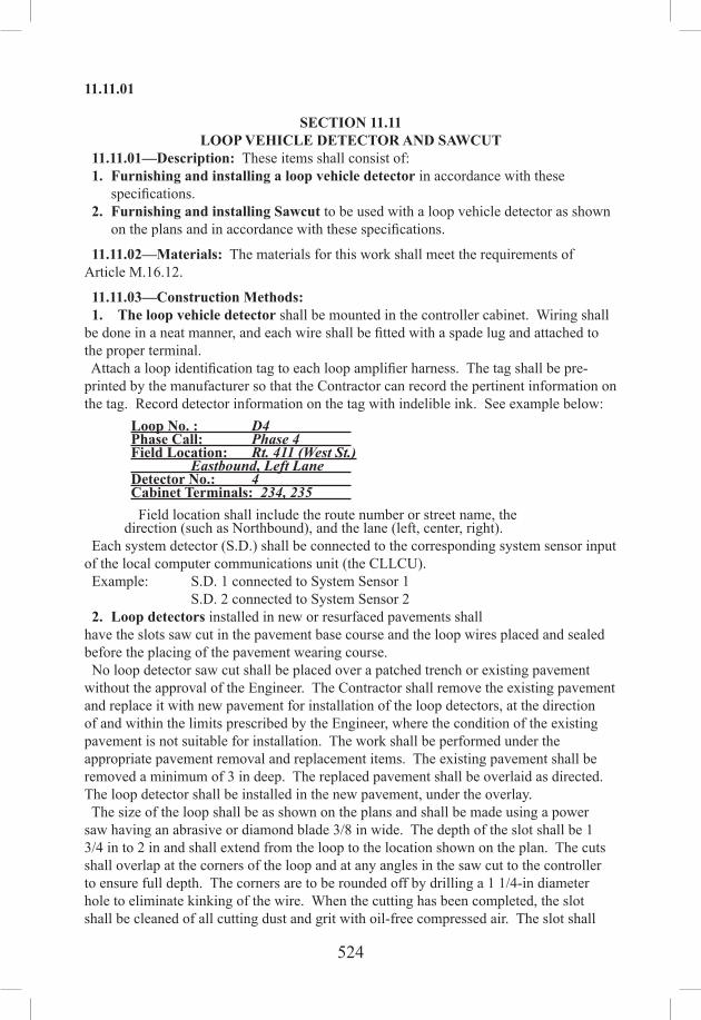
524
11.11.01
SECTION 11.11LOOP VEHICLE DETECTOR AND SAWCUT
11.11.01—Description: These items shall consist of: 1. Furnishing and installing a loop vehicle detector in accordance with these
specifications. 2. Furnishing and installing Sawcut to be used with a loop vehicle detector as shown
on the plans and in accordance with these specifications.
11.11.02—Materials: The materials for this work shall meet the requirements of Article M.16.12.
11.11.03—Construction Methods: 1. The loop vehicle detector shall be mounted in the controller cabinet. Wiring shall be done in a neat manner, and each wire shall be fitted with a spade lug and attached to the proper terminal. Attach a loop identification tag to each loop amplifier harness. The tag shall be pre‑printed by the manufacturer so that the Contractor can record the pertinent information on the tag. Record detector information on the tag with indelible ink. See example below:
Loop No. : D4 Phase Call: Phase 4 Field Location: Rt. 411 (West St.) Eastbound, Left Lane Detector No.: 4 Cabinet Terminals: 234, 235 Field location shall include the route number or street name, the
direction (such as Northbound), and the lane (left, center, right). Each system detector (S.D.) shall be connected to the corresponding system sensor input of the local computer communications unit (the CLLCU). Example: S.D. 1 connected to System Sensor 1
S.D. 2 connected to System Sensor 2 2. Loop detectors installed in new or resurfaced pavements shall have the slots saw cut in the pavement base course and the loop wires placed and sealed before the placing of the pavement wearing course. No loop detector saw cut shall be placed over a patched trench or existing pavement without the approval of the Engineer. The Contractor shall remove the existing pavement and replace it with new pavement for installation of the loop detectors, at the direction of and within the limits prescribed by the Engineer, where the condition of the existing pavement is not suitable for installation. The work shall be performed under the appropriate pavement removal and replacement items. The existing pavement shall be removed a minimum of 3 in deep. The replaced pavement shall be overlaid as directed. The loop detector shall be installed in the new pavement, under the overlay. The size of the loop shall be as shown on the plans and shall be made using a power saw having an abrasive or diamond blade 3/8 in wide. The depth of the slot shall be 1 3/4 in to 2 in and shall extend from the loop to the location shown on the plan. The cuts shall overlap at the corners of the loop and at any angles in the saw cut to the controller to ensure full depth. The corners are to be rounded off by drilling a 1 1/4-in diameter hole to eliminate kinking of the wire. When the cutting has been completed, the slot shall be cleaned of all cutting dust and grit with oil-free compressed air. The slot shall

525
11.11.05
be completely dry before inserting the wire. The entire loop and lead-in shall consist of 1 continuous #14 stranded wire encased in tubing, unless otherwise shown on the plans. The lead-in wires shall be twisted together with at least 5 turns per ft and taped at 2-ft intervals, beginning at a point where the wire leaves the saw cut and enters the plastic conduit to the terminals in the controller cabinet, or when spliced to a 2-conductor lead-in cable. The twisted wire shall remain together and shall not be coiled at any point. Splices will not be permitted at any point of the loop or lead-in unless otherwise indicated on the plans or as directed by the Engineer. At the time of installing the loop wire, the ends of the tubing shall be sealed to prevent any entrance of moisture into the tubing. When splices are required in handholes or junction boxes, they shall be made in accordance with the installation details. The saw cuts on all lead-ins shall be as shown on the plans or as directed by the Engineer. The number of turns of wire for each loop shall be as shown on the plans. After installation, the wire shall be checked for slack or raised portions in the saw cut slot. A paint mix stick or similar blunt instrument shall be used to push the wire in the slot. The wire shall be held in the slot with wooden pegs or by inserting wedges formed from 1-in sections of the plastic tubing, folded before insertion. The loop shall be tested prior to sealing the saw cut. An unacceptable loop installation would consist of leakage to ground below 10 megohms or an open circuit. The saw cut shall then be filled with plastic compound to a level of approximately 1/16 in below the pavement surface. In no case shall the plastic compound overflow the saw cut and all excess material shall be removed. The plastic compound shall be applied in accordance with the manufacturer’s recommendations. The plastic compound shall adhere to the sides of the saw cut and not show a separation when pressure is applied by a blunt instrument. Each pair of lead‑in wires in the cabinet shall be tagged and identified to determine phase and geographical location of each loop, Example-: “Phase 4—East End Bank St.—Right Lane.” When a 1-part urethane elastomeric compound is used to seal the sawcut the manufacturer’s installation procedure shall be followed. The sawcut, complete and tested with wire installed and retained with plastic wedges, shall be filled with the elastomeric compound from the bottom up. The sawcut shall be filled to 0.125 in from the surface of the pavement. The elastomeric compound shall not be applied if the pavement surface temperature is less than 40oF or more than 100oF.
11.11.04—Method of Measurement: This work will be measured for payment as follows: 1. Loop vehicle detectors will be measured for payment by the number of loop vehicle detectors of the type specified, completed, operating and accepted in place. 2. Loop Detector Saw Cut: The quantity to be paid for under this item shall be the actual number of linear feet of saw cut, measured along the center of the cut, with #14 Stranded Wire encased in tubing completely installed, tested and accepted in place. #14 Stranded Wire encased in tubing shall not be measured for payment separately but shall be included in the measurement for saw cut.
11.11.05—Basis of Payment: 1. Loop vehicle detector will be paid for at the Contract unit price each for “Loop Vehicle Detector” of the type specified, which price shall include connecting cable,

526
11.12.01
sensor unit, all materials, labor and work incidental thereto. 2. Loop detector saw cut will be paid for at the Contract unit price per linear foot of “Loop Detector Saw Cut,” which price shall include; saw cut, #14TW stranded wire (including that to handholes, traffic control foundations or controller cabinets), necessary fittings, flexible plastic tubing, plastic compound, splicing and connecting, equipment, labor, materials and work incidental thereto.
Pay Item Pay UnitLoop Vehicle Detector (Type) ea.Loop Detector Saw Cut l.f.
SECTION 11.12MAGNETIC VEHICLE DETECTOR
11.12.01—Description: This item shall consist of furnishing and installing a magnetic vehicle detector of the type specified at the location shown on the plans, or as indicated by the Engineer and in accordance with these specifications.
11.12.02—Materials: The materials for this work shall meet the requirements of Article M.16.13.
11.12.03—Construction Methods: The magnetic detector shall be installed in a 4-in polyvinyl chloride conduit. A joint shall be made to the control cable in the concrete handhole. Joints shall be made in accordance with Article 11.13.03. The single lane magnetic detector shall be placed in a roadway excavation made only large enough to permit the pavement box and conduit to be lowered into place. Reinforcing rods in concrete need only to be removed within 5 in or 6 in of the detector housing. Remove the detector coil unit and other parts from the pavement box, replace the cover and install the conduit using pipe joint compound to prevent the entrance of moisture. The pavement box and conduit assembly will be suspended in the excavation using 4 bolts and 2 in x 4 in wood pieces as temporary supports. The cover of the box shall be 3 in below the finished surface of the roadway. Plug up the unused conduit entrances with pipe plugs. Spread a handful of sand over the cover to prevent concrete from getting into the cracks. Place concrete in the excavation up to the level of the top surface of the box. After the concrete has hardened, the cover shall be removed and the coil unit placed in the box with the “arrow” pointing toward the intersection. After the coil connections have been made, a silicone compound shall be applied to the terminals. The conduit entrances shall be sealed with oakum or equivalent and fill the entire pavement box with melted petrolatum (Vaseline) or equivalent. The cover shall then be secured in place and the road resurfaced to its original level.
11.12.04—Method of Measurement: This work will be measured for payment by the number of magnetic vehicle detectors of the type specified, completed, operating and accepted.
11.12.05—Basis of Payment: This work will be paid for at the Contract unit price each for “Magnetic Vehicle Detector,” of the type specified, which price shall include detector, detector‑amplifier, all materials, labor, tools and work incidental thereto.
Pay Item Pay UnitMagnetic Vehicle Detector (Type) ea.

527
11.13.03
SECTION 11.13CONTROL CABLE
11.13.01—Description: This item shall consist of furnishing and installing electrical cable and appurtenances of the type specified at the locations shown on the plans or as indicated by the Engineer, in accordance with these specifications.
11.13.02—Materials: The materials for this work shall meet the requirements of Article M.16.14.
11.13.03—Construction Methods: All wiring shall meet the appropriate requirements for the NEC and shall be insulated for 600 volts. Wire splicing will not be permitted in conduit or outside of junction boxes, hand holes, poles or pedestals, unless otherwise indicated on the plans. All cables shall contain the required number of conductors as shown on the plans. The substitution of several cables to attain the required number of conductors will not be permitted. Cable to be installed in conduit shall be pulled with a minimum of dragging on the ground or pavement. This shall be accomplished by means of reels mounted on jacks or approved devices conveniently located for unreeling cable directly into the conduit. Powdered soapstone, talc, or other approved lubricants shall be used when inserting cable into the conduit. Cable shall be pulled through conduit by means of a cable or cables. Wiring within junction boxes and cabinets shall be neatly arranged. Conductors entering the controller cabinet shall be neatly dressed and laced along the base and back of the cabinet to the terminal board mounted in the cabinet. When 3 or more conductors are attached to the same terminal in the controller cabinet, they shall not be twisted together, but shall be attached with a set-screw type lug of the correct size. When less than 3 conductors are attached to the same terminal, in the controller cabinet, a separate spade type connector shall be attached to each conductor. Spare conductors shall be tied together with their ends taped. All splices are to be of an approved type and made in such a manner that the connection will be moisture-proof. All aerial splices shall be accomplished as shown on the plans using a cable closure. At least 2 ft of slack shall be left for each conductor at each standard and at least 1 ft of slack at each pull box. All splicing in junction boxes, hand holes, poles and pedestals can be accomplished by one of the following methods: 1. Splices can be made by soldering with the pouring or dipping method. 2. Non-insulated butt-type pressure connectors shall be seamless and be UL approved for aluminum or copper wire. The butt-type pressure connector shall be connected to the wire with an installing tool that is designed for butt-type pressure connectors. After crimping, all detector cable splices shall also be soldered. Each butt-type connector shall be insulated separately by applying layers of thermoplastic electrical insulating tape. The thermoplastic tape shall extend 1/2 in beyond the conductor insulation and be lapped at 1/4-in intervals. The entire completed splice shall have an application of layers of 30 mil high voltage rubber self-fusing tape well lapped over and equal to the original insulation. The splice shall then be covered with layers of thermoplastic electrical insulating tape not over 0.007 in thick meeting the requirements of MILSPEC‑7798 and a coating of flexible insulating paint approved by the Engineer. At least 1 ft of slack shall be left for each conductor at each splice. An approved type of water-tight splicing box may be used in lieu of the aforementioned, providing the box has

528
11.13.04
sufficient number of terminals to accommodate the number of conductors to be spliced in the box. When conductors and cables are pulled into conduits, all ends of conductors and cables shall be taped to exclude moisture, and shall be so kept until the splices are made or terminal appliances attached. 3. Cable closures shall be installed as shown on the plans or as directed by the Engineer. The cable closure shall be attached to the span or messenger with suspension brackets. After the cables have been installed, each opening shall be sealed with sealing tape. When using cable less than 0.6 in in diameter, a cone-shaped collar shall be formed with sealing tape, to seal off the space between the cable and closure nipple. Two (2) turns of sealing tape shall then be placed over the closure nipple and the cable. The cable shall be attached to the terminal blocks as shown on the typical installation details. The terminals shall then be securely wrapped with electrical tape. Connectors shall not extend beyond the end of the terminal post. The terminals and connectors shall not be in contact with the closure cover at any point.
11.13.04—Method of Measurement: This work will be measured as follows: 1. The quantity of control cable to be paid for under these items shall be the actual number of linear feet measured along the center of the cable specified, installed, tested and accepted in place with the necessary connections. 2. Cable closures will be measured for payment by the number of cable closures of the type specified, completed and accepted in place.
11.13.05—Basis of Payment: 1. Control cable shall be paid for at the Contract unit price per linear foot for “(No.) Conductor # ( ) (Type)” which price shall include installation, splicing, connecting, necessary fittings, equipment, labor, all materials and work incidental thereto. 2. Cable closure will be paid for at the Contract unit price for “Cable Closure” complete, in place, which price shall include all materials, sealing tape, terminal blocks and all equipment, tools, labor and work incidental thereto.
Pay Item Pay Unit(No.) Conductor #( )(Type) l.f.Cable Closure ea.
SECTION 11.14MESSENGER AND SPAN WIRE
11.14.01—Description: Work under this item shall consist of furnishing and installing span wire or messenger, whichever is applicable, at the locations indicated on the plans or as directed by the Engineer.
11.14.02—Materials: The materials for this work shall meet the requirements of Article M.16.15.
11.14.03—Construction Methods: 1. SpanWireusedforthesuspensionoftrafficsignals shall be attached to the supporting poles at such a level as to make the lowest part of the signal head not less than 16 ft 0 in, nor more than 17 ft 0 in above the pavement grade beneath the signal head. A normal sag of not more than 5% of the total span shall be permitted. Wire secured to the pole bands shall be protected from sharp bends by a thimble clevis. Thimble

529
11.16.03
eyebolts, nuts and washers shall be used instead of eyebolts. Ends of cable shall be fastened to the standing part by 6-in clamps and shall be wrapped with galvanized wire. A wet porcelain strain insulator shall be used at locations where the messenger or span wire is attached between steel and wood poles. Traffic signal control cable shall be suspended from the span wire by means of 2-in or 3-in rings as required by the number and size of the cables installed, spaced not more than 18 in apart. The traffic signal cable may be suspended from the messenger with the use of 2-in rings, or by a spiral wrapping of 3/32-in galvanized steel wire, applied by a machine in a uniform spiral with a lay or pitch of no more than 18 in. All overhead conductors shall have an 8-in drip loop at the junction with a pole or signal head. At all electrical cable turns and drops, plastic tie wraps shall be used to insure against any change in physical relationship between the electrical cable and the span wire. Service wires between a power supply and controller cabinet on a pole shall be connected to the pole by an approved cable grip and enter the poles by means of a wire inlet with a bushing. An 8-in drip loop shall be formed in the wires at the entrance of the wire inlet. The installation of span wire shall be as shown on the plans. 2. Messenger for carrying signal cable between poles shall be installed as shown on the plans. The suspension of cable shall conform to either the 2-in or 3-in ring or spiral wrapping methods, which are covered elsewhere in this specification.
11.14.04—Method of Measurement: Work under these items will be measured for payment by the actual number of linear feet of steel wire cable, of the type specified, installed and accepted in place with necessary appurtenances.
11.14.05—Basis of Payment: This work will be paid for at the Contract unit price per linear foot for “Messenger Wire” or “Span Wire (Type),” whichever applies, which price shall include messenger or span wire, wet porcelain insulators, pole bands, thimble eyebolts, nuts, washers, cable rings, all materials, tools, equipment, labor and work incidental thereto.
Pay Item Pay UnitMessenger Wire l.f.Span Wire (Type) l.f.
SECTION 11.16ILLUMINATED SIGNS
11.16.01—Description11.16.02—Materials11.16.03—Construction Methods11.16.04—Method of Measurement11.16.05—Basis of Payment
11.16.01—Description: This item shall consist of furnishing and installing an illuminated sign, of the type specified, at the location shown on the plans or as directed by the Engineer, and in accordance with these specifications.
11.16.02—Materials: The materials for this work shall be as specified in Article M.16.18.
11.16.03—Construction Methods: Erection of the sign shall be accomplished in

530
11.16.04
a manner so as not to cause twisting, bending, deforming, or scratching of the sign or sign face. Signs shall be level, correctly aligned as indicated on the plans and shall be properly fastened to the structure or supports with the necessary hardware as indicated on the plans. Any sign panel damaged shall be repaired at the Contractor’s expense.
11.16.04—Method of Measurement: This work will be measured for payment by the number of illuminated signs of the type and size specified, completed in place, accepted and operating.
11.16.05—Basis of Payment: This work shall be paid for at the Contract unit price each for “Overhead Illuminated “Stop Ahead” Sign” or “Internally Illuminated Sign” complete in place, which price shall include mounting brackets, hardware, fittings, snap switch, all materials, equipment, paint, tools, labor, and work incidental thereto. Cable to the sign shall be paid as specified in Article 11.13.
Pay Item Pay UnitOverhead Illuminated “Stop Ahead” Sign ea.Internally Illuminated Sign ea.
SECTION 11.17ALTERNATE FLASHING SIGNALS FOR WARNING SIGNS
11.17.01—Description: Work under this item shall consist of furnishing and installing alternate flashing signals for warning signs at the location shown on the plans or as directed by the Engineer.
11.17.02—Materials: The materials for the work shall be as specified in the following: Article M.15.09 for Rigid Metal Conduit Article M.16.06 for Traffic Signals Article M.16.09 for Painting Article M.16.10 for Cabinet Article M.16.14 for Control Cable
11.17.03—Construction Methods: All internal wiring shall be #14 AWG stranded drawn copper. All wiring shall be neat and firm. All flasher inputs and outputs shall be wired to a terminal block. The signal indications and flasher cabinet shall be mounted on the sign supports in accordance with the dimensions and details shown on the plans.
11.17.04—Method of Measurement: This work will be measured for payment by the number of alternate flashing signals for warning signs completed and accepted in place. The conduit and cable installed on the line side of the cabinet will not be included for payment under this item.
11.17.05—Basis of Payment: This work will be paid for at the Contract unit price each for “Alternate Flashing Signals for Warning Signs,” which price shall include cable, signals, conduit, fittings, hardware, flasher cabinet complete with all necessary equipment, ground rod, armored ground cable, paint and painting, and all materials, equipment, tools and labor incidental thereto.
Pay Item Pay UnitAlternate Flashing Signals for Warning Signs ea.

531
11.18.05
SECTION 11.18REMOVAL AND/OR RELOCATION OF TRAFFIC
SIGNAL EQUIPMENT 11.18.01—Description: Work under this item shall consist of removal and, where required, relocation of existing traffic signal equipment at the location shown on the plans or as directed by the Engineer.
11.18.02—Materials: All materials required for this work shall meet the requirements of these specifications or the special provisions for the material in question; or if not so specified, they shall be of a quality satisfactory to the Engineer.
11.18.03—Construction Methods: Existing traffic signal equipment shall be carefully removed together with all fittings and attachments in such a manner as to safeguard all parts from damage or loss. The Contractor shall replace, at its own expense, all equipment which becomes damaged due to its operations. Removal of existing signal and control equipment shall be coordinated with the installation of new signal and control equipment so as to maintain uninterrupted traffic signal operation at each intersection. The Contractor shall furnish and install signals, supports or other equipment necessary to provide for uninterrupted signal operation as directed by the Engineer. Traffic signal equipment, fittings, wires, cable, conduit and all other materials shall be reinstalled and extended where necessary to maintain satisfactory operations. Where attachment points for span wire or other signal equipment are on a utility pole, the Contractor shall secure from the owning utility company the permission to remove or install such attachments in accordance with the utility’s requirements. Equipment shall be removed in such a manner as to cause no hazard to pedestrians, traffic or property. If necessary, flaggers shall be used to halt traffic briefly while work is in progress. When plans call for relocation of existing equipment, the work shall be accomplished with a minimum of down time. All removed equipment, including wire and cable that is not reused at the location, is to be returned to the State at a location designated by the Engineer. Material, such as concrete foundations, etc. shall be suitably removed and disposed of by the Contractor. When poles, foundations, etc. are removed, the hole shall be backfilled with clean fill material, which shall be compacted and the ground restored to a grade and condition compatible with the surrounding area. Topsoil to a minimum depth of 4 in shall be applied and seeded with perennial grass seed. If in a sidewalk area, the surfacing shall be with material compatible with the rest of the sidewalk. Where pressure sensitive vehicle detectors are to be removed, the entire detector frame shall be removed, the hole shall be backfilled and the pavement restored, in accordance with the appropriate sections of the Standard Specifications.
11.18.04—Method of Measurement: This work shall be at the Contract lump sum price for the completion of all work specified.
11.18.05—Basis of Payment: This work will be paid for at the Contract lump sum price for the “Removal and/or Relocation of Traffic Signal Equipment” which price shall include all removals, all relocations, all material, equipment and labor incidental to

532
11.30.01
completion of this item. Pay Item Pay UnitRemoval and/or Relocation of Traffic Signal Equipment l.s.
SECTION 11.30HIGH MOUNTED INTERNALLY ILLUMINATED
FLASHING ARROW 11.30.01—Description: This item shall include furnishing and maintaining a high mounted internally illuminated flashing arrow sign, either on a trailer assembly or truck, as shown on the traffic control plans or as ordered by the Engineer and in accordance with these specifications.
11.30.02—Materials: The flashing arrow shall meet the requirements of Part 6 of the MUTCD, Arrow Boards, Type C. The panel shall have the capability of both sequential and flashing operations. The bottom of the panel shall not be less than 7 ft above the pavement. Lamp voltage shall be dimmed by 50% for nighttime use automatically.
11.30.03—Construction Methods: The Contractor shall furnish, place, operate, maintain and relocate the sign as required. When the need no longer exists for a sign, the Contractor shall dispose of it. Any signs that are missing, damaged, defaced, or improperly functioning so that they are not effective, as determined by the Engineer and in accordance with the ATSSA guidelines contained in “Quality Standards for Work Zone Traffic Control Devices,” shall be replaced by the Contractor at no cost to the State. 11.30.04—Method of Measurement: This work will be measured for payment by the number of calendar days that the sign is in place and in operation. When a sign is in operation for less than a day, such a period of time shall be considered to be a full day regardless of actual time in operation.
11.30.05—Basis of Payment: This work will be paid for at the Contract unit price per day for “High Mounted Internally Illuminated Flashing Arrow,” which price shall include all costs for furnishing, maintaining and disposing of a sign and all materials, labor, tools and equipment incidental thereto.
Pay Item Pay UnitHigh Mounted Internally Illuminated Flashing Arrow day
SECTION 11.31CHANGEABLE MESSAGE SIGN
REMOTE CONTROLLED CHANGEABLEMESSAGE SIGN
11.31.01—Description: Work under this item shall include furnishing and maintaining a trailer-mounted, Changeable Message Sign or Remote Controlled Changeable Message Sign, whichever is applicable, at the locations indicated on the plans or as directed by the Engineer.
11.31.02—Materials: The internally illuminated variable message sign shall consist of a magnetically operated matrix, LED, fiber optic, or lamp matrix message board; a diesel engine driven generator power supply; hardware for connection to a 110 volt power source; and a computer operated interface, all mounted on a towable, heavy duty trailer. The sign shall have a 3-line message panel with 8 characters per line and a minimum

533
11.31.05
horizontal dimension of 115 in. The letter height shall not be less than 18 in. The sign shall rotate a complete 360 degrees atop the lift mechanism. In the raised position, the bottom of the sign shall be at least 7 ft above the pavement surface. The sign shall be clearly legible for a distance of 900 ft. The sign shall be controlled by an on-board computer. The sign shall automatically change to a pre-selected default message upon failure. That default message shall remain on display until the problem is corrected. The Remote Controlled Changeable Message Sign unit shall be equipped with a security system to prevent unauthorized access. The security system shall allow access only through use of a code or password unique to that sign. If the proper code or password is not entered within 60 seconds of initial telephone contact, the call will be terminated. Remote control for the Remote Controlled Changeable Message Sign shall be by cellular telephone and touch tone modem decoder. Each element in a magnetically operated matrix message board shall consist of a moveable flap operated by an electromagnet, which shall be positioned so that by changing polarity the flap is reversed. When closed, the black side shall be exposed. When opened, the colored section shall be exposed. The lamp matrix, LED or fiber optic sign, shall be equipped with a top‑mounted photocell for automatic sign dimming during nighttime use. The sign shall be capable of storing 100 pre-programmed messages and be able to display any of those messages upon call via the trailer-mounted terminal for both the Changeable Message Sign and the Remote Controlled Changeable Message Sign or through the cellular telephone hookup for the Remote Controlled Changeable Message Sign.
11.31.03—Construction Methods: The Contractor shall furnish, place, operate, maintain and relocate the sign as required. When the sign is no longer required, it shall be removed and become the property of the Contractor. The cellular telephone required for the Remote Controlled Changeable Message Sign shall be provided to the Engineer, and subsequently returned to the Contractor. When the sign is not in use, it shall either be turned off or turned from view. Any signs that are missing, damaged, defaced or improperly functioning so that they are not effective, as determined by the Engineer and in accordance with the ATSSA guidelines contained in “Quality Standards for Work Zone Traffic Control Devices,” shall be replaced by the Contractor at no cost to the State.
11.31.04—Method of Measurement: This work will be measured for payment for each changeable message sign or remote controlled changeable message sign, whichever applies, furnished and installed, for the number of calendar days that the sign is in place and in operation, measured to the nearest day. When a sign is in operation for less than a day, such a period of time shall be considered to be a full day regardless of actual time in operation.
11.31.05—Basis of Payment: This work will be paid for at the Contract unit price per day for each “Changeable Message Sign” or “Remote Controlled Changeable Message Sign,” which price shall include placing, maintaining, relocating and removing the sign and its appurtenances and all material, labor, tools and equipment incidental thereto. Additionally, for the “Remote Controlled Changeable Message Sign,” the cellular

534
11.31.05
telephone service and telephone charges shall be included.
Pay Item Pay UnitChangeable Message Sign dayRemote Controlled Changeable Message Sign day

535
12.01.02
SECTION 12.00GENERAL CLAUSES FOR HIGHWAY SIGNING
12.00.01—General12.00.02—Shop Drawings12.00.03—Buried Cable12.00.04—Negotiations with Utility Company12.00.05—Sequence of Operations
12.00.01—General: It is the intent of the plans, specifications, and special provisions to provide for a complete signing system. The work shall include the furnishing of all materials incidental to the fabrication and erection of all signs and sign supports.
12.00.02—Shop Drawings: Before fabricating any portion of the Overhead and/or Cantilever Sign Supports, the Contractor shall submit shop drawings drawn to scale for review in accordance with Subarticle 1.05.02-3. These shop drawings shall include but not be limited to the following information. 1. All pertinent dimensions. 2. Complete details of the Overhead and/or Cantilever Sign Supports including camber and material designations.
12.00.03—Buried Cable: The Contractor is hereby cautioned that within the limits of any Project an illumination contract may be in force or have been completed, in which case buried cable may be present at or near the proposed locations for overhead sign support foundations and the cable may be energized. Any damage to existing buried cable shall be repaired in a satisfactory manner at no additional cost to the State.
12.00.04—Negotiations with Utility Company: Article 10.00.12 is supplemented by the following: The Contractor shall make all necessary arrangements with the District Electrical Maintenance Supervisor for locking and unlocking of the circuits on which any work is to be done, through the Engineer.
12.00.05—Sequence of Operations: Whenever a new or relocated sign, of any kind, is replacing an existing sign, the replaced sign shall be removed immediately after the new installation.
SECTION 12.01OVERHEAD SIGN SUPPORT
12.01.01—Description12.01.02—Materials12.01.03—Construction Methods12.01.04—Method of Measurement12.01.05—Basis of Payment
12.01.01—Description: Work under this item shall consist of furnishing, fabricating, transporting and erecting galvanized overhead sign supports of the type specified, at the locations indicated, in accordance with the requirements of the plans or as ordered.
12.01.02—Materials: Materials for this work shall meet the requirements of Articles M.03.05, M.06.02, M.18.01 and M.18.02.

536
12.01.03
12.01.03—Construction Methods: Prior to the start of fabrication of the overhead sign supports, the Contractor shall, in the field, verify the location of the foundations and establish and verify all elevations, dimensions and longitudinal grades. All welding shall meet the requirements of the current AWS Structural Welding Code. All connections using high-strength bolts shall meet the requirements of Subarticle 6.03.03-4 (f) High Strength Bolted Connections. Camber shall be interpreted as the curvature induced into the overhead sign support truss to offset the anticipated deflections when the truss is in its erected position and to provide for the permanent camber as indicated on the plans. Cambers shall be measured in this erected position and failure to meet the required amount of camber may be cause for rejection. Prior to assembly, the top and bottom surface of the base plate shall be planed, or else the plate shall be hot straightened. The post shall be faced at the bottom end. The top leveling nuts and the grout-leveling template shall be removed prior to placing the base plate and post assembly upon the foundation. The base plate and post assembly shall be installed upon the foundation pedestal in accordance with the requirements of Subarticle 6.03.03-4(c) Bearings. After placing the base plate and post assembly upon the foundation, the anchoring nuts shall be installed “snug tight” and then tightened additionally in accordance with Subarticle 6.03.03-4 (f) High Strength Bolted Connections Turn-of-Nut Installation Method, modified as follows: Nut rotation from the snug tight condition shall be 1/4 turn. The posts shall have a removable top cap, complete with set screws for proper attachment. The cap shall be provided with a weatherproof ventilation passageway to the interior of the post. The galvanized Overhead Sign Support shall have damaged galvanized areas repaired in accordance with ASTM A780.
12.01.04—Method of Measurement: This work will be measured for payment by the number of units of “Overhead Truss Sign Supports” or “Overhead Cantilever Sign Supports” of the type specified, installed and accepted.
12.01.05—Basis of Payment: This work will be paid for at the Contract unit price each for “Overhead Truss Sign Support” or “Overhead Cantilever Sign Support” of the type specified, complete in place, which price shall include all materials, equipment, labor, tools, and work incidental thereto.
Pay Item Pay UnitOverhead Truss Sign Support (Type) ea.Overhead Cantilever Sign Support (Type) ea.
SECTION 12.02OVERHEAD SIGN SUPPORT FOUNDATION
12.02.01—Description: Work under this item shall consist of the construction of foundations for overhead sign supports including the removal and satisfactory disposal of all materials required for excavation for the foundations, and backfilling with suitable material, in conformity with the requirements of the plans or as ordered, and in conformance with these specifications.
12.02.02—Materials: Class “A” Concrete shall meet the pertinent requirements of

537
12.02.03
Sections 6.01 and M.03. Non-shrink, non-staining grout shall meet the requirements of M.03.05. Reinforcing steel shall meet the requirements of Section 6.02 and Article M.06.01. Rigid metal conduits, ground rod sleeves and related hardware shall be as shown on plans. Anchor bolts shall meet the requirements of ASTM A449. Leveling nuts and nuts for anchor bolt assemblies shall meet the requirements of Article M.18.02. Pedestal Grout Leveling Templates shall meet the requirements of Article M.18.02.
12.02.03—Construction Methods: Prior to start of construction of the foundations the Contractor shall, in the field, verify the location of the foundations and establish and verify all elevations and dimensions. Excavation for the footings shall conform to the neat lines of the base as shown on the plans. All steel reinforcement shall be accurately placed in the position shown on the plans and firmly held during placing and setting of concrete. The footing of the concrete foundation shall be placed without forms except where unusual soil conditions prevent excavation to neat lines as shown on the plans. Where unusual soil conditions make the use of forms necessary, in the opinion of the Engineer, the cost thereof shall be considered included in the cost of the foundations. Where rock ledge or large boulders are exposed before excavation has attained the required depth, the Engineer may order rock anchors installed. Where rock anchors are required, they shall be paid for in conformance with Article 1.04.05. After the concrete for the footing has sufficiently set, in the opinion of the Engineer, the portion of the concrete foundation, hereinafter designated as the stem, shall be formed to conform to the details shown on the plans. The forms shall include a template to hold the required anchor bolt assemblies, ground rod sleeve and conduit in their correct position. Anchor bolt assemblies shall conform to the requirements shown on the plans and shall be embedded in the concrete which shall be placed to within the minimum distance of the finished surface of the stem as shown on the plans forming a construction joint for the non‑shrink grout. Each bolt of the anchor bolt assembly shall be fitted with 2 leveling nuts. Construction joints other than those shown on the plans will not be permitted. The top and bottom surfaces of the grout-leveling template shall be planed, or else the plate shall be hot straightened. The grout-leveling template shall be clamped in position by 2 leveling nuts at each anchor bolt. These leveling nuts shall be adjusted to assure a truly level finished foundation surface at the proper elevation. The space between the grout-leveling template and pedestal concrete shall be grouted with non-shrink, non-staining grout. The grout shall be forced by rodding or by other suitable means from one side of the template until it flows freely out at the opposite side. Care shall be taken to eliminate voids underneath the template. Before grouting, the concrete areas that will be in contact with the grout shall be cleaned of all loose or foreign material that would in any way prevent bond between the grout and concrete surfaces. These concrete surfaces shall be kept thoroughly moistened until the surface is completely saturated prior to placing the grout. The grout shall be moisture

538
12.02.04
cured for 7 days. No load shall be allowed on the grout that has been in place for less than 7 days unless otherwise approved by the Engineer. The grout-leveling template shall remain in place for a minimum of 2 days after placement of the grout. All conduits shall be capped with insulated bushings before placing the grout. Where the signs are not to be illuminated, the caps shall be made fully watertight. The number of conduits in the foundation will be determined by the Engineer. The concrete shall be finished in conformance with the pertinent requirements of Subarticle 6.01.03‑10. Backfill shall be placed and thoroughly tamped to the elevation shown on the plans.
12.02.04—Method of Measurement: This work will be measured for payment by the number of foundation units, of the type specified, completely installed and accepted. Each overhead cantilever sign support shall have 1 foundation unit and each overhead truss sign support shall have 2 foundation units.
12.02.05—Basis of Payment: The work will be paid for at the Contract unit price each for “Overhead Sign Support Foundation,” of the type specified, complete in place, which price shall include all materials, excavation, backfill, equipment, labor, tools and work incidental thereto including rigid metal conduits and ground rod sleeve with 5/8 in X 12 ft ground rod driven in position as directed by the Engineer.
Pay Item Pay UnitOverhead Truss Sign Support Foundation (Type) ea.Overhead Cantilever Sign Support Foundation (Type) ea.
SECTION 12.03SIDE MOUNTED SIGN FOUNDATION
12.03.01—Description: Work under this item shall consist of all necessary excavation including rock excavation, backfill, when necessary, and the construction of side mounted sign foundations conforming to the details shown on the plans.
12.03.02—Materials: Concrete shall be Class “A” Concrete meeting the pertinent requirements of Sections 6.01 and M.03. Reinforcing steel shall meet the pertinent requirements of Section M.06.01. Stub post assemblies shall be steel meeting the requirements of ASTM A36 and shall be galvanized after fabrication in accordance with ASTM A123. All other material shall meet the requirements shown on the plans.
12.03.03—Construction Methods: Excavation for the foundation shall be to the neat lines as shown on the plans. The concrete foundation shall be placed without forms except where unusual soil conditions prevent excavation to neat lines as shown on the plans. The forms shall be fastened in place before the placing of any concrete so that the resulting foundation will be monolithic. The anchor bolts or stub post assembly and reinforcing steel shall be fabricated and preset as shown on the plans. After pre-setting the stub post, concrete shall be carefully placed and consolidated around the post.
12.03.04—Methods of Measurement: This work will be measured for payment by the number of units completely installed and accepted.

539
12.04.05
12.03.05—Basis of Payment: This work will be paid for at the Contract unit price each for “Side-Mounted Sign Foundation,” which price shall include all material, excavation including rock excavation, stub post assembly, breakaway coupling system, forms when necessary, labor and work incidental thereto.
Pay Item Pay UnitSide-Mounted Sign Foundation ea.
SECTION 12.04SIGN PANEL OVERLAY
12.04.01—Description: Work under this item shall consist of furnishing and installing a plywood overlay of the type specified to cover an existing sign where shown on the plans or where directed by the Engineer.
12.04.02—Materials: Plywood paneling shall have a minimum thickness of 1/4 in and shall be exterior grade A-C as designated by APA. Wood preservative shall be a penetrating solution having a minimum of 20% of copper or zinc naphthenate. Primer shall meet the requirements of FS TT-P-25. The paint to be used for the finish coat shall be as specified in Article M.18.08. Copy shall meet the requirements contained in M.18.09 or M.18.10, as specified in the plans.
12.04.03—Construction Methods: The plywood overlay shall completely cover the sign including the exit crown panel. The plywood sheets shall be joined together to form a single sign covering by means of 1 in x 4 in construction grade fir wood battens securely fastened to adjoining panels with 1 in galvanized wood screws. The battens shall be fastened to the back face of the overlay. Before assembly and before painting, all wood shall be treated with a coat of wood preservative on all sides. The wood preservative shall be of a type which will have no adverse effect on paint adhesion and will not cause future paint discoloration. The entire sign shall be painted with 1 coat of primer and 1 coat of enamel. The completed sign overlay shall be fastened to the erected sign by means of approved steel “C” clamps. A minimum of 1 “C” clamp shall be used for every 2 ft of sign perimeter. The “C” clamps shall be tightened to ensure the plywood sign covering will remain in place. All work fabricating and clamping the plywood sign panel overlay shall be done to ensure that no damage occurs to the sign.
12.04.04—Method of Measurement: Sign panel overlay of the type specified will be measured for payment by the actual number of square feet installed and accepted.
12.04.05—Basis of Payment: This work will be paid for at the Contract unit price per square foot for “Sign Panel Overlay,” of the type specified complete in place, which price shall include all materials, equipment, tools and labor incidental thereto.
Pay Item Pay UnitSign Panel Overlay—Plain s.f.Sign Panel Overlay—with Copy s.f.

540
12.05.01
SECTION 12.05DELINEATORS
12.05.01—Description: This item shall consist of furnishing and installing delineators of retroreflective material and delineator posts or bridge rail mountings in accordance with the requirements of the plans or as ordered.
12.05.02—Materials: The materials for delineators shall be as specified in Articles M.18.07 and M.18.13. Retroreflective sheeting shall be as specified in Article M.18.09.
12.05.03—Construction Methods: Delineators shall be mounted on the posts or bridge rail mountings with fastening devices as shown in the details on the plans. The spacing and color of the delineators shall be in accordance with the plans or as directed by the Engineer. The delineator post shall be driven or the hole augered and the backfill thoroughly tamped. The posts shall be plumb above ground, and any post bent or otherwise damaged to the extent that it is, in the opinion of the Engineer, unfit for use, shall be removed from the Site and replaced by the Contractor at its own expense. The delineator retroreflective units shall be positioned to be clearly visible for a distance of 1,000 ft during the hours of darkness, under normal weather and atmospheric conditions, when illuminated by the upper beams of standard automobile headlights when the vehicle is located in the adjacent traffic lane approaching the delineator.
12.05.04—Method of Measurement: This work will be measured for payment by the number of delineators of the type specified, installed and accepted.
12.05.05—Basis of Payment: This work will be paid for at the Contract unit price each for “Delineator,” of the type specified, complete in place, which price shall include the delineator, delineator post or bridge rail mounting and materials, equipment, tools and labor incidental thereto.
Pay Item Pay UnitType DE-( ) Delineator ea.
SECTION 12.06REMOVAL OF EXISTING SIGNING
REMOVAL OF EXISTING OVERHEAD SIGNING 12.06.01—Description: This work shall consist of removing designated side-mounted signs, supports and foundations; plywood and/or sheet aluminum regulatory, warning and guide signs and metal sign posts; delineators and delineator posts; overhead signs, supports and foundations; and structure mounted sign and supports where indicated on the plans or as directed by the Engineer.
12.06.02—Vacant
12.06.03—Construction Methods: Signs constructed of plywood and the hardware used for attachment to the supports shall be removed and disposed of by the Contractor. Signs constructed of aluminum and the hardware used for attachment to the supports shall be removed and disposed of by the Contractor, unless otherwise specified in the Special Provisions. Delineators and delineator posts shall be removed and disposed of by the Contractor. Sign supports and sign illumination appurtenances shall be removed and disposed of by

541
12.07.02
the Contractor unless otherwise specified in the Special Provisions. When signs and supports are to be delivered to a salvage location specified in the Special Provisions, the Contractor shall transport and carefully unload the signs and supports where directed by the storekeeper. Overhead sign support foundations shall be removed to a depth of 6 in below finished grade. Anchor bolts shall be cut approximately flush with the top of the remaining portion of foundation. The concrete and portions of the anchor bolts removed from the foundation shall be disposed of by the Contractor. For-side-mounted sign foundations, the stub post or anchor bolts and concrete foundations shall be removed to a depth of 6 in below finished grade. The portion of stub posts or anchor bolts and the concrete removed shall be disposed of by the Contractor. Where sign support foundations exist without stub posts or anchor bolts, the Contractor will have the option of removing the concrete foundation in its entirety or remove the concrete and post to a depth of 6 in below finished grade. Whichever option the Contractor chooses, the Contractor shall remove the excavated material from the Site. After removal of all concrete, stub post portions and anchor bolt portions, top soil shall be placed to 1 in above finished grade, then fertilized and seeded. Fertilizing and seeding shall be in accordance with pertinent provisions of Section 9.50. Where necessary, backfill shall be placed to 6 in below grade before topsoil is placed. Supports located in bituminous concrete or Portland cement concrete areas shall be removed flush with the surrounding area and disposed of by the Contractor. Posts attached to bridge parapets or railings shall be unbolted and the anchor bolts removed flush with the bridge parapet and all material shall be disposed of by the Contractor.
12.06.04—Method of Measurement: This work will be at the Contract lump sum price, which shall include all signs, sign supports and foundations, if applicable, and delineators designated for removal in the Contract.
12.06.05—Basis of Payment: This work will be paid for at the Contract lump sum price for “Removal of Existing Signing” or “Removal of Existing Overhead Signing” complete including the disposal of material unless otherwise specified, and all equipment, material, tools and labor incidental thereto. The price shall also include the transporting and careful unloading of salvaged material at the location designated in the Special Provisions and all equipment, material, tools and labor incidental thereto.
Pay Item Pay UnitRemoval of Existing Signing l.s.Removal of Existing Overhead Signing l.s.
SECTION 12.07SIGN FACE - EXTRUDED ALUMINUM
12.07.01—Description: This item shall consist of furnishing and installing sign face extruded aluminum with the Type IV retroreflective sheet facing at locations indicated on the plans or as ordered and in accordance with the plans and these specifications.
12.07.02—Materials: Materials for this work shall meet the requirements of Articles M.18.09, M.18.10, M.18.11 and M.18.12. Structural steel shall meet the requirements of ASTM A36. All members shall be galvanized after fabrication in accordance with the requirements of ASTM A123.

542
12.07.03
Zinc paint shall meet the requirements of FS TT-P-641 Type 1.
12.07.03—Construction Methods: Erection of completed sign panels shall be accomplished in a manner so as not to cause twisting, bending or deforming of sign panels or scratching of the sign face. Any sign panel damaged shall be repaired or replaced at the Contractor’s expense. Sign panels shall be level, correctly aligned as indicated on the plans, and shall be properly fastened to the structure or supports with the necessary hardware as indicated on the plans. Retroreflective sheeting shall be applied in such a manner that the finished sign will be wrinkle and bubble free. No splices of the retroreflective sheeting will be permitted on any sign face under 30 s.f. in area with 1 dimension of 4 ft or less and no more than 1 splice will be permitted on any sign without the approval of the Engineer. Extruded aluminum signs shall be attached to existing supports with new post clip assemblies consisting of post clips, bolt, nut and washer as shown on the plans. All other hardware used for attachment of the overhead signs to the supports may remain in use and be relocated on the structure as required. Check and tighten all bolts and nuts for attachment hardware which is to remain in use. New extruded aluminum signs shall be vertically centered on existing supports. Overhead sign support brackets (Z bar, I bar, channel shape or angle iron) that project beyond the top or bottom of a new sign shall be cut to fit even with the edge of the new sign, preferably at the bottom. If necessary, cuts may be made at both ends. Where overhead signs having a vertical dimension exceeding the length of the existing sign support brackets, the existing brackets shall be removed and replaced with new vertical brackets having the length equal to the sign height. All galvanized areas damaged by field cuts or welds shall receive zinc paint that is brush applied to achieve a dry film thickness from 3 to 6 mils. All overhead sign erections shall be made immediately upon removal of the sign being replaced. All overhead sign foundations shall be field staked. The locations of the stakes shall be accepted by an Engineer from the Division of Traffic Engineering, a minimum of 7 days prior to installation. For all side mounted signs, the edge of the sign closest to the roadway and the sign foundation shall be field staked and accepted by an Engineer from the Division of Traffic Engineering, a minimum of 7 days prior to installation. For side-mounted signs, the offset to the near edge of the sign face shall exceed the maximum deflection of the guide rail, unless otherwise shown on the plans or directed by the Engineer.
12.07.04—Method of Measurement: This work will be measured for payment by the number of square feet of sign face‑extruded aluminum of the type specified installed and accepted.
12.07.05—Basis of Payment: This work will be paid for at the Contract unit price per square foot for “Sign Face‑Extruded Aluminum” of the type specified complete in place, which price shall include all materials, equipment, labor and work incidental thereto. Also included shall be any additional vertical sign support brackets required to attach new signs to existing supports.

543
12.08.03
Pay Item Pay UnitSign Face - Extruded Aluminum (Type) s.f.
SECTION 12.08SIGN FACE - SHEET ALUMINUM
12.08.01—Description: This item shall consist of furnishing and installing sign face-sheet aluminum signs of the type specified, metal sign posts, span‑mounted sign brackets and mast arm-mounted sign brackets at locations indicated on the plans or as ordered and complying with the requirements of the plans and these Specifications.
12.08.02—Materials: Retroreflective sheeting shall meet the requirements of Article M.18.09, Type IV or IX. Sheet aluminum sign blanks shall meet the requirements of Article M.18.13. Silk screening of Type IV or IX retroreflective sheeting shall meet the requirements specified by the retroreflective sheeting manufacturer. Metal sign posts shall meet the requirements of Article M.18.14. Sign mounting bolts shall meet the requirements of Article M.18.15.
12.08.03—Construction Methods: Placement and dimensions of copy, border and mounting holes shall be as shown in details of the Department of Transportation for Regulatory Warning and Guide signs which are available for inspection at the Department of Transportation office. Non‑reflective copy, border and background shall be applied by the silk‑screen process in a manner specified by the retroreflective sheeting manufacturer. The silk screening of all copy, border and background on Type IV or IX retroreflective sheeting shall be accomplished prior to the application of the retroreflective sheeting to the finished aluminum sign blank. Type IV or IX retroreflective sheeting shall be of the heat activated adhesive type and shall be applied in a manner specified by the retroreflective sheeting manufacturer. Retroreflective sheeting shall be applied in such a manner that the finished sign will be wrinkle and bubble free. No splices of the retroreflective sheeting will be permitted on any sign face under 30 s.f. in area with 1 dimension of 4 ft or less and no more than 1 splice will be permitted on any sign without the approval of the Engineer. Direct application of cutout Type IV or IX retroreflective sheeting copy and border shall meet the requirements specified by the retroreflective sheeting manufacturer. Cutout copy and border shall be applied directly to clean, dust free reflective sheeting background panels. Borders shall be cut neatly and butt-joined at corners and panel joints. Type IV or IX retroreflective sheeting used for direct applied cutout copy and border shall be uniform in brightness and color. The fabrication of aluminum sign blanks including cutting to size and shape and the punching of mounting holes shall be completed prior to metal degreasing and the application of retroreflective sheeting. Aluminum sign blanks shall be free of buckles, warp, dents, cockles, burrs and defects resulting from fabrication. Span-mounted sign brackets and mast arm-mounted sign brackets shall be installed as shown on the plans. After complete fabrication of the sign as indicated on the plans and in compliance with the requirements contained in the Specifications, the sign shall be mounted on the type of support designated on the plans after the support has been satisfactorily installed at its proper location. The reinforcing plate shall be installed as shown on the plans. Metal sign posts shall be driven or the holes augered and the backfill thoroughly tamped

544
12.08.04
after the posts have been set level and plumb.
12.08.04—Method of Measurement: This work will be measured for payment by the number of square feet of sign face‑sheet aluminum of the type specified, installed and accepted.
12.08.05—Basis of Payment: This work will be paid for at the Contract unit price per square foot for “Sign Face‑Sheet Aluminum” of the type specified complete in place, which price shall include the completed sign, metal sign post(s), span-mounted sign brackets and mast arm-mounted brackets, mounting hardware, including reinforcing plates, and all materials, equipment, labor and work incidental thereto.
Pay Item Pay UnitSign Face - Sheet Aluminum (Type) s.f.
SECTION 12.09PAINTED PAVEMENT MARKINGS
12.09.01—Description: This item shall consist of furnishing and installing painted pavement markings, hot applied painted pavement markings and painted legend, arrows and markings, of the type and color specified at the locations indicated on the plans and in accordance with the plans, these specifications, and as directed by the Engineer. Painted legend, arrows, and markings includes paint installed with a hand striping machine such as: stop bars, crosswalks, parking stalls, lane arrows, legends, markings within gore areas, and painting of paved islands or medians. Painted pavement markings and hot applied painted pavement markings include paint installed with a truck-mounted painting machine such as center lines, lane lines and shoulder lines. The exact location for passing zones will be determined by the Engineer prior to the application of the pavement markings. The Engineer shall be notified a minimum of 2 weeks before the anticipated date of painting, to allow time for the determination of the passing zone locations.
12.09.02—Materials: Materials for this work shall meet the requirements of Article M.07.20 for waterborne pavement marking paint, Article M.07.21 for hot-applied waterborne pavement marking paint and Article M.07.30 for glass beads.
12.09.03—Construction Methods: Pavement areas to be painted shall be dry and sufficiently cleaned of sand and road debris so as to provide an acceptable bond between the paint and the pavement. Paint shall be applied at a rate of 100 to 115 s.f./gal., with glass beads applied at a rate of 6 lb./gal. of paint for painted pavement markings and painted legend, arrows, and markings, and 8 lb./gal. of paint for hot-applied painted pavement markings. Hot-applied paint shall be applied at a temperature of 130°F to 145°F at the spray gun. All painting shall be performed in a neat and workmanlike manner. The lines shall be sharp and clear with no feathered edging or fogging, and precautions shall be taken to prevent tracking by tires of the striping equipment. Paint shall be applied parallel to the centerline or as shown on the plans with no unsightly deviations. After application, the paint shall be protected from crossing vehicles for a time at least equivalent to the drying time of the paint.
12.09.04—Method of Measurement: Painted pavement markings and hot-applied

545
12.10.03
pavement markings will be measured for payment by the number of linear feet of paint applied by a truck-mounted painting machine on the pavement and accepted. Painted legend, arrows and markings will be measured for payment by the number of square feet of paint installed with a hand striping machine on the pavement and accepted.
12.09.05—Basis of Payment: This work will be paid for at the Contract unit price per square foot for “Painted Legend, Arrows and Markings” and per linear foot of paint for “Painted Pavement Markings” or “Hot-Applied Painted Pavement Markings,” of the width and color specified, installed on the pavement and accepted. This price shall include all pre-marking layout, cleaning of pavement, paint, glass beads, application of paint and glass beads, protection during drying and all materials, equipment, tools and labor incidental thereto.
Pay Item Pay UnitPainted Legend, Arrows and Markings s.f.Painted Pavement Markings (Width) (Color) l.f.Hot-Applied Painted Pavement Markings (Width) (Color) l.f.
SECTION 12.10EPOXY RESIN PAVEMENT MARKINGS
12.10.01—Description12.10.02—Materials12.10.03—Construction Methods12.10.04—Method of Measurement12.10.05—Basis of Payment
12.10.01—Description: This item shall consist of furnishing and installing retroreflective white and yellow epoxy resin pavement markings of the width and color specified and epoxy resin pavement markings, symbols and legends at the locations indicated on the plans, in conformity with the plans and as directed by the Engineer. Epoxy resin pavement markings includes epoxy resin installed with a truck-mounted machine such as center lines, lane lines, and shoulder lines. Epoxy resin pavement markings, symbols and legends include stop bars, crosswalks, parking stalls, lane arrows, legends, and markings within areas such as paved islands, gore areas and paved medians. The exact location for passing zones will be determined by the Engineer prior to the application of the pavement markings. The Contractor shall notify the Engineer of the anticipated date of installation at least 2 weeks prior to that date, to allow time for the determination of the passing zone locations.
12.10.02—Materials: Materials for this work shall meet the requirements of Article M.07.22.
12.10.03—Construction Methods: 1. Equipment: Equipment furnished shall include an applicator truck of adequate size and power, together with (a) remote application equipment designed to apply an epoxy resin material in a
continuous pattern and (b) portable glass bead applicators, 1 for each size bead, designed to provide uniform

546
12.10.03
and complete coverage of the epoxy binder by a controlled free-fall method. Pressurized glass bead application shall not be used.
Before epoxy color is changed, equipment shall be cleaned out sufficiently to ensure that the color of material applied will be correct. When working on a highway with more than 1 lane in either direction, the applicator truck (striper) shall have a permanently mounted direction variable illuminated arrow board, fully operational and visible to approaching traffic. There will be no additional payment for the arrow board, but the cost shall be included in the bid price for this item. For markings applied on pavements over 1 year old, equipment furnished shall also include a power washing machine capable of cleaning the pavement with a pressure of 2,400 to 2,800 psi, with water heated to between 180 and 195°F. No chemicals shall be added to the water used in the process. The power washer shall be equipped with a turbo blast tip with an oscillating head and shall be capable of supplying a minimum of 5 gal./minute at the gun. All guns on the spray carriages shall be in full view of the operator(s) during operation. Each vehicle furnished shall include at least 1 experienced operator, who shall be fully knowledgeable about all equipment operations and application techniques. The Contractor shall also furnish 1 technical expert, who shall be fully knowledgeable about all equipment operations and application techniques, to oversee the Project operation. 2. Procedures: Pavement markings shall be applied in accordance with the details shown on the plans and the control points established by the Contractor and approved by the Engineer. The road surface shall be cleaned at the direction of the Engineer just prior to application. Pavement cleaning shall consist of power washing using clean water heated to between 180 and 195°F at a pressure of 2,400 to 2,800 psi. The areas to be power washed shall include all areas where epoxy marking symbols and legends (including stop bars and crosswalks) are to be applied and at least 1 in beyond the area to be marked. The surface shall be cleaned to the satisfaction of the Engineer. For other pavement areas, cleaning shall consist of brushing with rotary broom (non-metallic), and any additional work as recommended by the material manufacturer and acceptable to the Engineer. New Portland cement concrete surfaces shall be cleaned by abrasive blasting to remove any surface treatments or laitance. New bituminous concrete surfaces are not to be power washed. All surfaces that are power washed shall be allowed to dry sufficiently prior to the application of the epoxy markings. The areas to be marked shall be broom cleaned immediately prior to the application of the epoxy markings. Glass beads shall be applied immediately after application of the epoxy resin marking to provide an immediate no-track system. The Contractor shall place necessary “spotting” at appropriate points to provide horizontal control for striping and to determine necessary starting and cutoff points. Broken line intervals will not be marked. Longitudinal joints, pavement edges and existing markings shall serve as horizontal control when so directed. A tolerance of 0.25 in under or 0.25 in over the specified width shall be allowed for striping provided the variation is gradual and does not detract from the general appearance. Alignment deviations from the control guide shall not exceed 2 in provided

547
12.10.03
the variation is gradual and does not detract from the general appearance. Material shall not be applied over a longitudinal joint. Establishment of application tolerances shall not relieve the Contractor of the responsibility to comply as closely as practicable with the planned dimensions. Operations shall be conducted only when the road surface temperature is at least 40°F or as allowed by the Engineer. They shall be discontinued during periods of rain, and shall not continue until the Engineer determines that the pavement surface is dry enough to achieve adhesion. The epoxy shall be uniformly applied to the surface to be marked to ensure a wet film thickness of the applied epoxy, without glass beads, of 20 mils +/- 1 mil. Glass beads meeting the requirements of Grading “B” (larger beads) shall be applied at a rate of 12 lb./gal. of epoxy pavement marking material, immediately followed by a second drop of glass beads meeting the requirements of Grading “A” (smaller beads) applied at a rate of 13 lb./gal. of epoxy pavement marking material. Traffic cones or some other acceptable method shall be used to protect the pavement markings until cured. Time to No-Track: The material shall be in “no-tracking” condition within 15 minutes, or as allowed by the Engineer. The no-tracking time shall be determined by passing over the line with a passenger car or pickup truck in the simulated passing maneuver. A marking showing no visual deposition of the material to the pavement surface when viewed from a distance of 50 ft shall be considered as showing “no-tracking” and meeting this requirement for time to no-track. When stencils are used during the application of epoxy markings, care must be used when removing the stencils so that the epoxy resin does not drip on the road, sidewalk, grass, or other surfaces, and so that the applied markings have edges which are clean, straight and neat. Epoxy resin pavement markings may be applied over existing painted markings provided the existing markings are sufficiently worn to allow adequate adhesion. If required by the Engineer, existing plastic, thermoplastic, epoxy or freshly painted markings shall be removed prior to the application of epoxy markings. Payment for removal will be made under the item “Removal of Pavement Markings.” 3. Initial Performance: The retroreflectivity of the markings applied must be measured by the Contractor 3 to 14 days after installation. A Certified Test Report (CTR), in accordance with Article 1.06.07, must be submitted to the Engineer no later than 10 days after the measurements are taken using the procedures and equipment detailed below: Test Lots - The following test lots will be randomly selected by the Engineer to represent the line markings applied:
Table 12.10.03-3.1: Line Test LotsLength of line Number of Lots Length of Test Lot
< 1.0 mi. 1 1000 ft≥1.0 mi. 1 per 1.0 mi. 1000 ft
Measurement Equipment and Procedure Portable Retroreflectometer1. Skip line measurements shall be obtained for every other stripe, taking no more than

548
12.10.04
2 readings per stripe with readings no closer than 20 in from either end of the marking.2. Solid line test lots shall be divided into 10 sub-lots of 100 ft length and measurements obtained at 1 randomly select location within each sublot.3. For symbols and legends, 10% of each type shall be measured by obtaining 5 measurements at random locations on the symbol or legend.4. The Apparatus and Measurements shall be made in accordance with ASTM E1710 (Standard Test Method for Measurement of Retroreflective Pavement Marking Materials with CEN‑Prescribed Geometry Using a Portable Retroreflectometer) and evaluated in accordance with ASTM D7585 (Standard Practice for Evaluating Retroreflective Pavement Markings Using Portable Hand‑Operated Instruments). Mobile Retroreflectometer1. Calibration of the instruments shall be in accordance with the manufacturer’s instructions. 2. Retroreflectivity shall be measured in a manner proposed by the Contractor and approved by the Engineer. The basis of approval of the test method will be conformance to a recognized standard test method or provisional standard test method. The measurements shall be obtained when the pavement surface is clean and dry and shall be reported in millicandelas per square foot per foot candle - mcd/ft2/fc. Measurements shall be obtained sequentially in the direction of traffic flow.AdditionalContentsofCertifiedTestReport The CTR shall also list:1. Project and Route number2. Geographical location of the test site(s), including distance from the nearest reference point3. Manufacturer and model of retroreflectometer used4. Most recent calibration date for equipment used5. Grand Average and standard deviation of the retroreflectivity readings for each line, symbol or legendInitial Performance: In order to be accepted, all epoxy resin pavement markings must meet the following minimum retroreflectivity reading requirement: White Epoxy: minimum retroreflectivity reading of 400 mcd/ft2/fc Yellow Epoxy: minimum retroreflectivity reading of 325 mcd/ft2/fc At the discretion of the Engineer, the Contractor shall replace, at its expense, such amount of lines, symbols and legends that the Grand Average reading falls below the minimum value for retroreflectivity. The Engineer will determine the areas and lines to be replaced. The cost of replacement shall include all materials, equipment, labor and work incidental thereto. 4. Crosswalks: Only glass beads meeting the requirements of Grading “A” (smaller beads) shall be applied at a rate of 25 lb./gal. of epoxy pavement marking material.
12.10.04—Method of Measurement: Epoxy resin pavement markings shall be measured for payment by the actual number of linear feet of epoxy resin pavement markings installed on the pavement and accepted by the Engineer. Epoxy resin pavement markings, symbols and legends will be measured for payment by the actual number of

549
12.12.02
square feet of epoxy resin pavement markings, symbols and legends installed on the pavement and accepted by the Engineer.
12.10.05—Basis of Payment: This work shall be paid for at the Contract unit price per linear foot for “Epoxy Resin Pavement Markings” of the width and color specified, or the Contract unit price per square foot for “Epoxy Resin Pavement Markings, Symbols and Legends” installed on the pavement and accepted. These prices shall be for all the work required by this Section and all materials, equipment, tools and labor incidental thereto. Payment will not be made for pavement markings affected by Contractor error and ordered removed.
Pay Item Pay Unit(Width) (Color) Epoxy Resin Pavement Markings l.f.Epoxy Resin Pavement Markings, Symbols and Legends s.f.
SECTION 12.11REMOVAL OF PAVEMENT MARKINGS
12.11.01—Description: This item shall consist of removal of pavement markings, of the type specified, as called for on the plans or as directed by the Engineer.
12.11.03—Construction Methods: Pavement markings shall be removed from the pavement by any method that does not materially damage the surface or texture of the pavement. Any damage to the pavement surface caused by pavement marking removal shall be repaired by the Contractor at its expense by methods acceptable to the Engineer. Sand or other material deposited on the pavement as a result of removing pavement markings shall be removed as the work progresses. Accumulations of sand or other material which might interfere with drainage or might constitute a hazard to traffic will not be permitted. Protection of the work area shall be as indicated in the Specification for “Maintenance and Protection of Traffic.”
12.11.04—Method of Measurement: Work under this item will be measured for payment by the actual number of square feet of pavement markings removed.
12.11.05—Basis of Payment: This work shall be paid for at the Contract unit price per square foot for “Removal of (Type) Pavement Markings” of the type specified, which price shall include all materials, equipment, tools and labor incidental thereto. Payment will not be made for pavement markings installed by Contractor error and ordered removed by the Engineer.
Pay Item Pay UnitRemoval of (Type) Pavement Markings s.f.
SECTION 12.12TEMPORARY PLASTIC PAVEMENT MARKING
TAPE 12.12.01—Description: This item shall consist of furnishing, installing and removing temporary plastic pavement marking tape of the color and width specified at the locations shown on the plans or as directed by the Engineer.
12.12.02—Materials: Materials for this work shall be commercially available pavement marking tape designed and suitable for the purpose intended and readily removable, when required. The tape shall be retroreflective with the use of glass beads

550
12.12.03
throughout the pigments.
The marking tape shall be readily visible during daylight and when viewed with vehicular headlights at night. The marking tape shall be durable, flexible, formable and following application shall remain in contact with the pavement surface. The tape shall be reinforced by a non-metallic medium and pre-coated with a pressure sensitive adhesive.
12.12.03—Construction Methods: Installation of the pavement markings shall be performed in a neat and workman-like manner. The markings shall be applied parallel to the centerline or as shown on the plans or where directed by the Engineer with no unsightly deviations. The Contractor will pre-mark the pavement prior to application of the marking and use a string line if required to produce a neat appearing line. Removal shall be accomplished without the use of heat, solvents, grinding or sandblasting and in such a manner that no damage to the pavement results.
12.12.04—Method of Measurement: This work will be measured for payment by the actual number of linear feet of temporary plastic pavement marking tape acceptably installed on and removed from the pavement when it is no longer applicable or when its removal is directed by the Engineer.
12.12.05—Basis of Payment: This work will be paid for at the Contract unit price per linear foot for “Temporary Plastic Pavement Marking Tape” of the width and color specified, acceptably installed on and removed from the pavement. This price shall include all pre-marking layout, cleaning of pavement, application, removal and all materials, equipment, tools and labor incidental thereto. Payment will not be made for pavement markings installed by Contractor error and ordered removed by the Engineer. Any lines which are no longer effective, in the opinion of the Engineer and in accordance with the ATSSA guidelines contained in “Quality Standards for Work Zone Traffic Control Devices,” shall be replaced by the Contractor at no cost to the State. Removed markings shall become the property of the Contractor and shall be removed from the Project.
Pay Item Pay UnitTemporary Plastic Pavement Marking Tape (Width) (Color) l.f.
SECTION 12.14PREFORMED BLACK LINE MASK PAVEMENT
MARKING TAPE 12.14.01—Description: This item shall consist of furnishing, installing, and removing preformed, patterned, black line mask pavement marking tape of the width specified to temporarily cover existing pavement markings in accordance with this Section and in accordance with the plans and as directed by the Engineer. The preformed, patterned, black line mask pavement marking tape shall be a highly durable, skid resistant, non‑reflective, pliant polymer tape designed for the temporary covering of existing pavement markings. The black line mask pavement marking tape shall be removed when no longer needed, unless directed otherwise by the Engineer.

551
12.16.02
The black line mask pavement marking tape, when applied according to the recommendations of the manufacturer, shall provide a neat, durable masking that will not flow or distort. The black line mask pavement marking tape shall be weather resistant and, through normal traffic wear, shall show no lifting or shrinkage which will significantly impair the intended usage of the tape throughout its useful life and show no significant tearing or other signs of poor adhesion.
12.14.02—Materials: Materials for this work shall meet the requirements of Article M.07.24.
12.14.03—Construction Methods: The patterned, black line mask pavement marking tape shall be applied in accordance with the manufacturer’s recommendations, and shall mask the existing markings being covered.
12.14.04—Method of Measurement: Preformed black line mask pavement marking tape shall be measured for payment by the actual number of linear feet furnished, installed and removed.
12.14.05—Basis of Payment: This work shall be paid for at the Contract unit price per linear foot for “Preformed Black Line Mask Pavement Marking Tape” of the width specified. This price shall be for all the work required by this Section including the cleaning and preparing of the pavement surface, installation and removal, and all materials, equipment, tools and labor incidental thereto. Any masking tape which is no longer effective, in the opinion of the Engineer, shall be replaced by the Contractor at no cost to the State. Removed masking tape shall become the property of the Contractor and shall be removed from the Project.
Pay Item Pay Unit(Width) Preformed Black Line Mask Pavement Marking Tape l.f.
SECTION 12.16BLACK EPOXY RESIN PAVEMENT MARKINGS
BLACK EPOXY RESIN SYMBOLS AND LEGENDS 12.16.01—Description: This item shall consist of furnishing and installing black epoxy resin pavement markings of the width specified and black epoxy resin symbols and legends to cover existing markings in accordance with the plans or as directed by the Engineer. The black epoxy resin pavement markings and black epoxy resin symbols and legends shall be a highly durable, skid resistant, non‑reflective material designed to cover existing pavement markings. The black epoxy resin pavement marking material, when applied according to the recommendations of the manufacturer, shall provide a neat, durable masking that will not flow or distort. The black epoxy resin pavement marking material shall be weather resistant and, through normal traffic wear, shall show no wearing which would significantly impair the intended usage.
12.16.02—Materials: Materials for this work shall meet the requirements of Article M.07.25.

552
12.16.03
12.16.03—Construction Methods: The black epoxy resin pavement markings and black epoxy resin symbols and legends shall be applied strictly in accordance with the manufacturer’s recommendations and installed as shown on the plans and to the control points as established by the Engineer. The areas to be covered shall be dry and sufficiently cleaned of sand and debris so as to provide an acceptable bond. All surfaces which are power washed shall be allowed to dry sufficiently prior to the application of the epoxy markings. The areas that have been pre-marked shall be broom cleaned immediately prior to the application of the epoxy markings. Operations shall be conducted only when the road surface temperatures are 32°F or greater. Operations shall be discontinued during periods of rain, and shall not continue until the Engineer determines that the pavement surface is dry enough to achieve adhesion. Black aggregate shall be applied at a rate of 100 lb./gal. of black epoxy pavement marking material. The black aggregate shall be applied using a double drop bead system, with each drop distributing 50 lb./gal. of black epoxy pavement marking material. The black epoxy resin pavement markings shall extend approximately 1 in beyond the edges of the existing markings which are to be covered. After application, the pavement markings shall be protected from crossing vehicles for a time at least equivalent to the drying time of the material, as specified by the manufacturer.
12.16.04—Method of Measurement: Black epoxy resin pavement markings will be measured for payment by the actual number of linear feet of black epoxy resin pavement markings installed and accepted by the Engineer. Black epoxy resin symbols and legends will be measured for payment by the actual number of square feet of black epoxy resin symbols and legends installed and accepted by the Engineer.
12.16.05—Basis of Payment: This work will be paid for at the Contract unit price per linear foot for “Black Epoxy Resin Pavement Markings” of the width specified, or the Contract unit price per square foot for “Black Epoxy Resin Symbols and Legends” installed on the pavement and accepted. These prices shall be for all the work required by this Section including the cleaning and preparing of the pavement surface, and all materials, equipment, tools, and labor incidental thereto. Any black epoxy pavement marking material which is not effective, in the opinion of the Engineer, shall be replaced by the Contractor at no cost to the State.
Pay Item Pay Unit(Width) Black Epoxy Resin Pavement Markings l.f.Black Epoxy Resin Symbols and Legends s.f.
SECTION 12.20CONSTRUCTION SIGNS
12.20.01—Description: Under this item the Contractor shall furnish, install and remove construction signs with retroreflective sheeting and their required portable supports or metal sign posts that meet the requirements of NCHRP Report 350 (TL-3) or MASH for Category 2 Devices. The construction signs and their required portable supports or metal sign posts shall comply with the signing requirements stated in the item “Maintenance and Protection of Traffic,” as shown on the plans or as directed by the

553
12.20.03
Engineer. The Contractor shall furnish a sufficient number of signs to provide the signing patterns for all operations which are being undertaken concurrently.
12.20.02—Materials: Prior to using the construction signs and their portable supports, the Contractor shall submit to the Engineer a copy of the Letter of Acceptance issued by the FHWA to the manufacturer documenting that the devices (both sign and portable support tested together) comply with the requirements of NCHRP Report 350 (TL-3) or MASH for Category 2 Devices. All sign faces shall be rigid and reflectorized and shall meet the requirements of Article M.18.09. If used as rigid substrate, sheet aluminum sign blanks shall comply with the requirements of Article M.18.13. Metal sign posts shall comply with the requirements of Article M.18.14. Application of retroreflective sheeting, legends, symbols, and borders shall comply with the requirements specified by the retroreflective sheeting manufacturer. Attachments shall be provided so that the signs can be firmly attached to the portable sign supports or metal posts without causing damage to the signs.
12.20.03—Construction Methods: The signs and their portable supports or metal posts shall comply with the requirements as shown on the plans and the latest edition of the “Manual on Uniformed Traffic Control Devices.” Drawings of the signs, showing placement and dimensions of legend and border, are available for inspection at the Division of Traffic, Connecticut Department of Transportation. Various types of portable sign supports may be used. These portable supports shall be fabricated in such a manner as to minimize the possibility of the signs being blown over or displaced by the wind from passing vehicles and are to be of a yielding type to withstand impact with minimal damage to the signs, supports, or vehicles. Portable sign supports shall be approved by the Engineer before they are utilized on the Project. Mounting height of signs on portable sign supports shall be a minimum of 1 ft and a maximum of 2 ft, measured from the pavement to the bottom of the sign. Signs in other than good condition shall be replaced with acceptable signs as determined by the Engineer. Suitable attachments shall be provided so that the signs can be firmly attached to the portable sign supports or metal posts without causing damage to the signs. The following types of construction signs shall not be used: mesh, non-rigid, roll-up, corrugated or waffle board types substrates, foam core and composite aluminum sign substrates. Field Performance: Retroreflective sheeting processed and applied to sign blank materials in accordance with the sheeting manufacturer’s recommendations, shall perform effectively for a minimum of 3 years. The retroreflective sheeting will be considered unsatisfactory if it has deteriorated due to natural causes to the extent that: 1) the sign is ineffective for its intended purpose when viewed from a moving vehicle
under normal day and night driving conditions; or 2) the coefficient of retroreflection is less than 100 when measured at 0.2 degree
observation angle and -4 degree entrance angle. All measurements shall be made after sign cleaning according to the sheeting manufacturer’s recommendations. Ineffective signs, as determined by the Engineer and in accordance with the ATSSA guidelines contained in “Quality Standards for Work Zone Traffic Control Devices,” shall

554
12.20.04
be replaced by the Contractor at no cost to the State. Signs and their portable sign supports or metal posts that are no longer required shall be removed from the Project and shall remain the property of the Contractor.
12.20.04—Method of Measurement: The work to furnish, install and remove construction signs will be measured for payment by the number of square feet of sign face delivered and used on the Project. Sign supports will not be measured for payment.
12.20.05—Basis of Payment: This item will be paid for at the Contract unit price per square foot for “Construction Signs,” delivered and used on the Project, which price shall include the signs, portable sign supports, metal sign posts and all hardware required to attach the sign to the support or posts. Each sign and support or posts furnished will be paid for once, regardless of the number of times used on the Project.
Pay Item Pay UnitConstruction Signs s.f.

555
13.00
SECTIONS 13.00, 14.00, 15.00, 16.00UTILITIES
Utilities paid under Sections 13.00, 14.00, 15.00 and 16.00 without a Special Provision will meet the requirements of the pertinent sections of the Standard Specifications for the specified item.
NOTES

556
18.00.01
SECTION 18.00GENERAL CLAUSES –
IMPACT ATTENUATION SYSTEMS18.00.01—Description18.00.02—Performance Criteria18.00.03—Materials18.00.04—Failure to Comply18.00.05—Delineation of Impact Attenuation System
18.00.01—Description: This work shall consist of furnishing and installing a vehicular impact attenuation system in accordance with the plans and specifications or as directed by the Engineer. This work shall also include construction of related structures required for the system.
18.00.02—Performance Criteria: These devices shall have approval in writing from FHWA documenting that they comply with the requirements of the NCHRP Report 350 or the AASHTO MASH for Category 3 Devices.
18.00.03—Materials: All materials for permanent systems shall be furnished new. If a temporary system is not furnished new, the Contractor shall document or demonstrate to the Engineer that the system meets the Specification. The Contractor shall submit a Materials Certificate for each system in accordance with Article 1.06.07.
18.00.04—Failure to Comply: In the event that, in the judgement of the Engineer, impact attenuation systems are not maintained adequately and safely on any part of the Project, or the Contractor does not move or relocate impact attenuation systems to meet construction requirements for the safety of the public when directed to do so by the Engineer, on any day, the sum of $1500.00 per system per day will be deducted from any money due the Contractor as a charge for failure to comply with this Specification.
18.00.05—Delineation of Impact Attenuation Systems: All impact attenuation systems shall have an attenuator reflector attached to the front of the system, as shown on the plans.
SECTION 18.02TYPE A — IMPACT ATTENUATION SYSTEM
18.02.01—Description18.02.02—Materials18.02.03—Construction Methods18.02.04—Method of Measurement18.02.05—Basis of Payment
18.02.01—Description: Work under this item shall consist of furnishing and installing permanent sand inertial barrier modules of the size and configuration shown on the Plans or as directed by the Engineer.
18.02.02—Materials: The system modules shall be chosen from the Department’s Qualified Products List. The color of the modules shall be yellow. The sand shall meet the requirements of Subarticle M.05.02-2, have a maximum moisture content of 3% and be thoroughly mixed with 20% sodium chloride by weight. Sodium chloride shall meet the requirements of AASHTO, M 143, Type 1, and Grade 1.

557
18.06.02
Delineators shall meet the requirements of Section M.18.
18.02.03—Construction Methods: The modules shall be assembled in accordance with the manufacturer’s recommendations and installed at the location on the Plans or as directed by the Engineer. Modules shall be installed on surfaces not exceeding a 10:1 slope. The Contractor shall paint each module’s weight on the pavement surface in the pattern designed. The Contractor shall fill each module with the sand‑salt mixture to the specified weight as shown on the Plans ±10 lb. and shall secure the lid.
18.02.04—Method of Measurement: Sand inertial barrier modules will be measured for payment by the number of modules for each specified weight installed and accepted by the Engineer.
18.02.05—Basis of Payment: Sand inertial barrier modules will be paid for at the Contract unit price for each “Type A Impact Attenuation Module” of the specified weight, which price shall include the delineator, all materials, equipment, tools and labor incidental to complete the installation.
Pay Item Pay UnitType A Impact Attenuation Module (Weight) ea.
SECTION 18.06TYPE D PORTABLE IMPACT ATTENUATION
SYSTEM 18.06.01—Description: This item shall consist of furnishing, installing, operating, maintaining, and relocating Truck Mounted Impact Attenuators (TMA) in accordance with the Contract, plans or as directed by the Engineer.
18.06.02—Materials: Prior to using a new TMA, the Contractor shall submit to the Engineer a materials certificate in accordance with Article 1.06.07 for each system supplied and a copy of the FHWA Letter of Acceptance issued to the manufacturer documenting that the device complies with the requirements of the NCHRP Report 350 (TL-3) or the AASHTO MASH for Category 3 Devices. If the system is not furnished new, the Contractor shall document and demonstrate to the Engineer’s satisfaction that the system complies with the requirements of a new system, as well as either NCHRP Report 350 (TL-2) or the AASHTO MASH, and may be used until the end of the attenuation device’s useful service life. The attenuation device shall be mounted on a truck or service vehicle similar in size and weight to the truck that was used in the crash testing that was submitted and approved by the FHWA. In addition, the truck shall have a minimum weight of 15,000 lb. and a maximum weight in accordance with the manufacturer’s recommendations. Any ballast used to obtain the minimum weight requirement, or any other object that is placed on the vehicle shall be anchored so that it will be retained on the vehicle in the event of an impact. The truck shall be equipped with an internally illuminated flashing arrow visible from the rear. The bottom of the illuminated arrow sign shall be installed a minimum of 7 ft above the ground. The illuminated arrow shall meet the requirements of Section 11.30. The truck shall be equipped with a minimum of 2 amber strobe type flashers mounted above the internally illuminated flashing arrow.

558
18.06.03
The TMA unit shall have a chevron pattern that covers the rear face of the unit. The standard chevron pattern shall consist of stripes, alternating non‑reflective black and Type IV retroreflective yellow sheeting, slanted at 45 degrees in an inverted “V” pattern, centered on the rear of the unit. The stripes shall be between 4 in and 8 in wide.
18.06.03—Construction Methods: The Contractor shall maintain each TMA in a fully operable condition at all times. Any TMA that is not fully functional will not be permitted at the Project Site. 1. Use of the TMA, as a stationary barrier vehicle shall be under the control of the
Engineer at all times, and shall comply with the following: A. The TMA shall be positioned so that traffic does not pass any other object within
the protected area (i.e. equipment, personnel, and vehicles) before reaching the TMA.
B. Each TMA in use shall be positioned between 25 ft and 100 ft before the area to be protected.
C. Each TMA shall be provided for use an assigned driver, who shall be available to reposition the TMA within a 15-minute time frame.
2. Use of the TMA as a shadow protection vehicle for mobile or stop and go operations shall be under the control of the Engineer at all times, and shall comply with the following:
A. The TMA shall be positioned so that approaching traffic does not reach or overtake any object before passing the TMA.
B. Each TMA in use shall be positioned between 50 ft and 200 ft from the rear of the next vehicle in the mobile array when the array is in a stopped position. When the array is in motion, the maximum distance between vehicles may extend to 500 ft, depending on the type and speed of the operation, road conditions, traffic volumes, etc.
C. Each TMA in use shall have an assigned driver, who must remain in the service vehicle at all times that the portable impact attenuation system is in use.
The disposal of crushed or damaged systems is the responsibility of the Contractor. The disposal method employed shall be approved by the Engineer.
18.06.04—Method of Measurement: This item will be measured for payment by the actual number of hours that the Type D Portable Impact-Attenuation System is used. Subject to the approval of the Engineer, Type D Portable Impact Attenuation Systems may be used as a High Mounted Internally Illuminated Flashing Arrow. If the Attenuation System is used as a Flashing Arrow, then it will be paid for under the item “High Mounted Internally Illuminated Flashing Arrow.”
18.06.05—Basis of Payment: This item shall be paid for at the Contract unit price per hour for “Type D Portable Impact Attenuation System, “ which shall include the furnishing and use of the specified vehicle and a driver, attenuation device, flashers, illuminated arrow, and all equipment, materials, tools, labor, disposal of damaged systems components and work incidental thereto.
Pay Item Pay UnitType D Portable Impact Attenuation System hr.

559
18.07.04
SECTION 18.07TEMPORARY IMPACT ATTENUATION SYSTEMS
18.07.01—Description: Work under this item shall consist of furnishing, installing, removing, repairing, and relocating temporary impact attenuation systems and modules of the type and size specified on the plans or as directed by the Engineer.
18.07.02—Materials: Temporary Type A impact attenuation modules shall meet the material requirements of Article 18.02.02. Material for other temporary systems shall be to the manufacturer’s specifications. A materials certificate as defined in Article 1.06.07 shall be submitted for each system supplied. The delineator shall meet the requirements of Section M18.
18.07.03—Construction Methods: Temporary impact attenuation systems and modules shall be installed at the locations shown on the plans according to the manufacturer’s specifications, or as directed by the Engineer. The Contractor shall relocate temporary impact attenuation systems and modules to locations within the Project limits shown on the plans or as directed by the Engineer. The Contractor shall remove all temporary impact attenuation systems and modules that are no longer needed on the Project. The temporary impact attenuation system and modules shall be maintained by the Contractor during all stages of construction. When required, the Contractor shall furnish replacement parts and repair the temporary impact attenuation system or modules as necessary, but no more than 72 hours after notification from the Engineer. Once the Contractor has begun repairs, the area shall remain protected and the work shall continue until all repairs are complete. The repaired temporary impact attenuation system or modules, when completed shall be to the manufacturer’s specifications for a new system. The Contractor shall be responsible for the removal and the proper disposal of all damaged material and debris.
18.07.04—Method of Measurement: Temporary Type A impact attenuation modules will be measured for payment by the number of each module installed and accepted by the Engineer. Other temporary impact attenuation systems will be measured for payment by the number of each system installed and accepted by the Engineer. Temporary Type A impact attenuation modules that are relocated to a new location shown on the plans or directed by the Engineer, including to and from the storage area, will be measured for payment by the number of each module relocated and accepted by the Engineer. Other temporary impact attenuation systems that are relocated to a new location shown on the plans or directed by the Engineer, including to and from the storage area, will be measured for payment by the number of each system relocated and accepted by the Engineer. Adjustment or realignment of any part of the system or modules for Contractor’s access or convenience will be done at the Contractor’s expense. The sum of money shown on the estimate and in the itemized proposal as “Estimated Cost” for repair of temporary impact attenuation systems or modules will be considered the price bid even though payment will be made only for actual work performed. The estimated cost figure is not to be altered in any manner by the bidder. Should the bidder

560
18.07.05
alter the amount shown, the altered figures will be disregarded and the original price will be used to determine the total amount bid for the Contract.
18.07.05—Basis of Payment: Temporary Type A impact attenuation modules will be paid for at the Contract unit price for each “Temporary Impact Attenuation System Type A Module (Weight) “ specified, complete in place. This price shall include furnishing, installation, removal, and all materials, maintenance, transportation, delineator, equipment, tools and labor incidental thereto. Other temporary impact attenuation systems will be paid for at the Contract unit price for each “Temporary Impact Attenuation System (Type) “ specified, complete in place. This price shall include furnishing, installation, removal, and all materials, maintenance, transportation, delineator, equipment, tools and labor incidental thereto. Relocation of temporary Type A impact attenuation modules will be paid for at the Contract unit price for each “Relocation of Temporary Type A Impact Attenuation Module” specified. This price shall include all materials, transportation, equipment, tools and labor incidental thereto. Relocation of other temporary impact attenuation systems will be paid for at the Contract unit price for each “Relocation of Temporary Impact Attenuation System (Type) “ specified. This price shall include all materials, transportation, equipment, tools and labor incidental thereto. “Repair of Temporary Impact Attenuation System” or modules will be paid for in accordance with Article 1.09.04 as required to restore the system or module to its full working condition in accordance with the Manufacturer’s recommendations or as directed by the Engineer. There will be no payment for maintenance and protection of traffic for work associated with this item unless, in the opinion of the Engineer, the sole purpose of the maintenance and protection of traffic is for repair of the attenuation system or module.
Pay Item Pay UnitTemporary Impact Attenuation System Type A Module (Weight) ea.Temporary Impact Attenuation System (Type) ea.Relocation of Temporary Type A Impact Attenuation Module ea.Relocation of Temporary Impact Attenuation System (Type) ea.Repair of Temporary Impact Attenuation System est.

561
NOTES

562
NOTES

563
NOTES

564
NOTES

565
NOTES

566
NOTES

567
M.01.01
DIVISION IIIMATERIALS SECTION
SECTION M.01GRADATION OF AGGREGATE
M.0.01—Gradation of Aggregate
M.01.01—Gradation table for sizes of crushed or broken stone, crushed and uncrushed gravel and reclaimed miscellaneous aggregate.
PERCENT PASSING BY WEIGHTNAME
SquareMeshSieves
No. 3 No. 4 No. 6 No. 67 No. 8 Screenings Dust
2 1/2 in 1002 in 90-100 100
1 1/2 in 35-70 90-1001 in 0-15 20-55 100 100
3/4 in 0-15 90-100 90-1001/2 in 0-5 20-55 1003/8 in 0-5 0-15 20-55 85-100 100No. 4 0-5 0-10 10-30 100
No. 8 0-5 0-10 60-100 40-100
No. 16 0-5
Reclaimed miscellaneous aggregate shall only be used where authorized in the specifications.

568
NOTES

569
M.02.02
SECTION M.02GRANULAR FILL
SUBBASEGRANULAR BASE AND SURFACES
STONE BASEPERVIOUS STRUCTURE BACKFILL
FREE‑DRAINING MATERIALCRUSHER‑RUN STONE
M.02.01—Granular FillM.02.02—SubbaseM.02.03—Granular Base, Rolled Bank Gravel Surface and Traffic Bound
Gravel SurfaceM.02.04—Gravel ShouldersM.02.05—Pervious Structure BackfillM.02.06—Gradation, Plasticity, Resistance to Abrasion and Soundness RequirementsM.02.07—Free‑Draining Materials
M.02.01—Granular Fill: For this purpose, the material shall consist of broken or crushed stone, gravel, reclaimed miscellaneous aggregate or a mixture thereof. 1. Broken or crushed stone shall be the product resulting from the artificial crushing of rocks, boulders or large cobblestones, substantially all faces of which have resulted from the crushing operation. Broken or crushed stone shall consist of sound, tough, durable stone, reasonably free from soft, thin, elongated, laminated, friable, micaceous or disintegrated pieces, mud, dirt or other deleterious material and shall be sized to meet the requirements of Grading “A,” Article M.02.06. 2. Bank or crushed gravel shall consist of sound, tough, durable particles of crushed or uncrushed gravel, free from soft, thin, elongated or laminated pieces and vegetable or other deleterious substances. It shall meet Grading “A” and the requirements for plasticity and resistance to abrasion indicated in Article M.02.06. Crushed gravel shall be the manufactured product resulting from the deliberate mechanical crushing of gravel with at least 50% of the gravel retained on the No. 4 sieve and having at least 1 fractured face. 3. Reclaimed Miscellaneous Aggregate material shall consist of sound, tough, durable particles of crushed reclaimed waste. It shall be free of soft disintegrated pieces, mud, dirt, glass or other injurious materials and contain no more than 2% by weight of asphalt cement. This reclaimed miscellaneous material shall meet Grading “A” and the requirements for plasticity and resistance to abrasion, which are set forth in M.02.06.
M.02.02—Subbase: Materials for this work shall conform to the following requirements:
1. Bank or crushed gravel shall consist of sound, tough, durable particles of crushed or uncrushed gravel, free from soft, thin, elongated or laminated pieces and vegetable or other deleterious substances. It shall be hard and durable enough to resist weathering, traffic abrasion and crushing. It shall meet Grading “B” and the requirements for plasticity and resistance to abrasion indicated in Article M.02.06.

570
M.02.03
2. Crusher‑Run Stone shall consist of sound, tough, durable broken stone. It shall be reasonably free from soft, thin, elongated, laminated, friable, micaceous or disintegrated pieces, mud, dirt or other deleterious material.(a) Loss on Abrasion: The crusher-run stone shall show a loss on abrasion of not more
than 50% using AASHTO Method T 96.(b) Grading: The crusher-run stone shall meet Grading “A” and the requirements for
plasticity indicated in Article M.02.06. 3. Reclaimed Miscellaneous Aggregate shall consist of sound, tough, durable particles of crushed reclaimed waste. It shall be free from soft, disintegrated pieces, mud, dirt, glass or other injurious material, and contain no more than 2% by weight of asphalt cement. This reclaimed miscellaneous material shall meet Grading “B” and the requirements for plasticity and resistance to abrasion, which are set forth in M.02.06.
M.02.03—Granular Base, Rolled Bank Gravel Surface and Traffic Bound Gravel Surface: The materials for the “Rolled Granular Base” shall consist of sound, tough, durable particles of bank or crushed gravel, or reclaimed miscellaneous aggregate, or mixtures thereof with the resultant uniform blend containing no more than 2% by weight of asphalt cement. The materials for the Rolled Bank Gravel Surface and Traffic-Bound Gravel Surface shall consist of sound, tough, durable particles of bank or crushed gravel. All materials shall be free from thin or elongated pieces, lumps of clay, loam, or vegetable matter. Binder may be added and incorporated by approved methods as specified elsewhere. It shall meet Grading “A” except that the top course of the rolled bank gravel surface shall conform to Grading “C.”
M.02.04—Gravel Shoulders: The materials for this work shall consist of sound, tough, durable particles of crushed or uncrushed, gravel free from soft, thin, elongated or laminated pieces, vegetable or other deleterious substances. Gravel shall meet Grading “A” except that the upper 3 in shall conform to Grading “C.”
M.02.05—Pervious Structure Backfill: Pervious structure backfill shall consist of broken or crushed stone, broken or crushed gravel, or reclaimed miscellaneous aggregate containing no more than 2% by weight of asphalt cement or mixtures thereof. Materials for this work shall conform to the following requirements: 1. Broken or crushed stone shall consist of sound, tough, durable stone, reasonably free from soft, thin, elongated, friable, laminated, micaceous or disintegrated pieces, mud, dirt or other deleterious material and shall be sized to meet the requirements of Grading “B,” Article M.02.06. It shall meet the requirements of loss on abrasion indicated in Subarticle M.02.02-2(a). 2. Bank or crushed gravel shall consist of sound, tough, durable particles of crushed or uncrushed gravel free from soft, thin, elongated or laminated pieces and vegetable or other deleterious substances. It shall meet Grading “B.” 3. Reclaimed Miscellaneous Aggregate shall consist of sound, tough, durable particles of crushed reclaimed waste. It shall be free of soft disintegrated pieces, mud, dirt, glass or other injurious material, and contain no more than 2% by weight of asphalt cement. It shall meet Grading “B.”
M.02.06—Gradation, Plasticity, Resistance to Abrasion and Soundness

571
M.02.06
Requirements: 1. Gradation:
Grading
A B C
Square Mesh Sieves Percent passing by weight
Pass 5 inch 100
Pass 3 1/2 inch 100 90-100
Pass 1 1/2 inch 55-100 55-95 100
Pass 3/4 inch 45-80
Pass 1/4 inch 25-60 25-60 25-60
Pass No. 10 15-45 15-45 15-45
Pass No. 40 5-25 5-25 5-25
Pass No. 100 0-10 0-10 0-10
Pass No. 200 0-5 0-5 0-5
The grading percentages specified in the above table shall apply to the material after it has been delivered to the construction site as well as when tested at the pit or other source of supply. When the fraction of the dry sample passing the No. 100 mesh sieve is greater than 8% by weight, the sample will be washed as indicated. The amount obtained from washing shall be added to that obtained by dry sieving; and the total amount passing each sieve shall meet the above gradation. 2. Plasticity: (a) When the fraction of the dry sample passing the No. 100 mesh sieve is 4% or less by weight, no plastic limit test will be made. (b) When the fraction of the dry sample passing the No. 100 mesh sieve is greater than 4% and not greater than 8% by weight, that fraction shall not have sufficient plasticity to permit the performing of the plastic limit test using AASHTO Method T 90. (c) When the fraction of the dry sample passing the No. 100 mesh sieve is greater than 8% by weight, the sample will be washed; and the additional material passing the No. 100 mesh sieve shall be determined by AASHTO Method T 146, except that the No. 100 mesh sieve will be substituted for the No. 40 mesh sieve where the latter is specified in AASHTO Method T 146. The combined materials that passed the No. 100 mesh sieve shall not have sufficient plasticity to permit the performing of the plastic limit test using AASHTO Method T 90. 3. Test for Resistance to Abrasion. Gravel materials shall show a loss on abrasion of not more than 50% using AASHTO Method T 96. 4. Soundness: When tested with magnesium sulfate solution for soundness using AASHTO Method T 104, coarse aggregate shall not have a loss of more than 15% at the end of 5 cycles.

572
M.02.07
M.02.07—Free‑Draining Materials: Free-draining material shall consist of sand, gravel, rock fragments, quarry run stone, broken stone, reclaimed miscellaneous aggregate containing no more than 2% by weight of asphalt cement or mixtures thereof. This material, or the material from any one source of a mixture, shall not have more than 70%, by weight, passing the No. 40 mesh sieve and not more than 10%, by weight, passing the No. 200 mesh sieve.

573
NOTES

574
M.03.01
SECTION M.03PORTLAND CEMENT CONCRETE
M.03.01—Component MaterialsM.03.02—Mix Design RequirementsM.03.03—Producer Equipment and Production RequirementsM.03.04—Curing MaterialsM.03.05—Non Shrink, Non Staining GroutM.03.06—Expansive Cement for AnchoringM.03.07—Chemical AnchorsM.03.08—Joint MaterialsM.03.09—Protective Compound/SealersM.03.10—Formwork
M.03.01—Component Materials 1. Coarse Aggregate: Coarse aggregate shall be broken stone, gravel, or reclaimed concrete aggregate defined as mortar-coated rock, consisting of clean durable fragments of uniform quality throughout. It shall be free from soft, disintegrated pieces, mud, dirt, organic or other injurious material and shall not contain more than 1% dust by mass, as determined by AASHTO T-11. Coarse aggregate of a size retained on a 1-in square opening sieve shall not contain more than 8% of flat or elongated pieces, whose longest dimension exceeds 5 times their maximum thickness. Heating or cooling of coarse aggregates may be required to meet concrete mix temperature requirements at time of placement. (a) Soundness: When tested with magnesium sulfate solution for soundness, using AASHTO Method T 104, coarse aggregate shall not have a loss of more than 10% at the end of 5 cycles. (b) Loss on Abrasion: When tested by means of the Los Angeles Machine, using AASHTO Method T 96, coarse aggregate shall not have a loss of more than 40%. (c) Gradation: Grading and stone sizes of the coarse aggregate shall conform to Article M.01.01 as determined by AASHTO T 27. All coarse aggregate proportions shall be approved in advance by the Transportation Division Chief (TDC) as part of the Mix Design requirements. (d) Storage: Aggregate stockpiles shall be located on smooth, hard, sloped/well-drained areas. Each source and gradation shall have an individual stockpile or bin. Aggregates shall be handled from stockpiles or other sources to the batching plant in such manner as to minimize segregation of the material. Aggregates that have become segregated, or mixed with earth or foreign material, shall not be used. (e) Reclaimed Concrete Aggregate: In addition to (a) through (d) above, when reclaimed concrete aggregate is proposed, it shall be tested for chloride content. If blended with virgin aggregate, reclaimed aggregate shall be tested prior to being mixed. The test used to determine chloride content shall be that outlined in AASHTO T 260 “Sampling and Testing for Chloride Ion in Concrete and Concrete Raw Materials.” Aggregate shall not be used if the chloride content as determined from this test exceeds 0.5 lb./c.y. Regardless of chloride content, reclaimed concrete aggregate shall not be used in concrete mixes used for pre-stressed concrete construction. 2. Fine Aggregate: Fine aggregate shall be natural or manufactured sand consisting of clean, hard, durable, uncoated particles of quartz or other rock, free from lumps of clay,

575
M.03.01
soft or flaky material, mica, loam, organic or other injurious material. In no case shall fine aggregate containing lumps of frozen material be used. Heating or cooling of fine aggregates may be required to meet concrete mix temperature requirements at time of placement. For continued shipments of fine aggregate from a given source, the fineness modulus of any sample shall not vary more than 0.20 from the base fineness modulus. The base fineness modulus for a source shall be established by the Engineer and may be revised based on current testing results. (a) Fine Material: Fine aggregate shall contain no more than 3% of material finer than a #200 sieve, as determined by AASHTO T 11. (b) Organic Impurities: Fine aggregate subjected to the colorimetric test shall not produce a color darker than Gardner Color Standard No. 11, using AASHTO T 21. If the fine aggregate fails to meet this requirement, the provisions of AASHTO M 6, Section 7.2.3, may apply. (c) Gradation: Fine aggregate gradation shall be within the ranges listed in Table M.03.01-1 for any source. All fine aggregate proportions shall be approved in advance by the TDC as part of the Mix Design requirements. (d) Soundness: When tested with magnesium sulfate solution for soundness, using AASHTO T 104, fine aggregate shall not have a loss of more than 10% at the end of 5 cycles. Fine aggregate that fails to meet this requirement, but meets all other requirements, may be allowed for use on a restricted basis with the approval of the Engineer on a case-by-case basis. Typically concrete forming any surface subject to polishing or erosion from running water will not be allowed to contain such material. (e) Storage: Aggregate stockpiles shall be located on smooth, hard, sloped/well-drained areas. Each source and gradation shall have an individual stockpile or bin. Aggregates shall be handled from stockpiles or other sources to the batching plant in such manner as to minimize segregation of the material. Aggregates that have become segregated, or mixed with earth or foreign material, shall not be used.
Table M.03.01‑1TOTAL % PASSING BY WEIGHT
Sieve Size 3/8” No. 4 No. 8 No. 16 No. 30 No. 50 No. 100
Percent Passing 100 95-
100 80-100 50-85 25-60 10-30 2-10
3. Cement: (a) Portland: Types I, II, and III Portland cement shall conform to the requirements of AASHTO M 85. Type I and Type III Portland cement shall be used only when required or expressly permitted by the Project specification or the Engineer. The use of Type I or III will require that these mixtures be submitted as Non-standard Mix Designs. All cement shall be provided by a mill participating in the Departments’ Cement Certification program. The requirements of the Certification Program are detailed in the Departments’ Quality Assurance Program for Materials. (b) Pre‑Blended Cements: Binary or Ternary cements consisting of Portland cement and supplemental cementitious materials may be used provided that all the requirements of Subarticles M.03.01-3(a) and -3(c) are met.

576
M.03.01
(c) Replacement Materials: Unless already approved as a Standard Mix Design, any Contractor-proposed Mix Designs with partial replacement of Portland Cement (PC) with fly ash or ground granulated blast furnace slab (GGBFS), shall be submitted in writing to the Engineer for approval prior to the start of work, on a project-by-project basis. The type of material, source, and the percentage of the PC replaced shall be clearly indicated. Upon request, a Certified Test Report for the cement replacement material shall be provided to the Engineer for use during the Mix Design review.
1. Fly Ash: Fly ash to be used as a partial replacement for Portland cement shall meet the requirements of AASHTO M 295, either Class C or Class F, including the uniformity requirements of Table 2A. Loss on Ignition for either class of fly ash shall not exceed 4.0%. Fly ash may be used to replace up to a maximum of 20% of the required Portland cement. The fly ash shall be substituted on a weight basis, with a minimum of 1 lb. of fly ash for 1 lb. of Portland cement. Different classes of fly ash or the same class from different sources shall not be permitted on any single project without the written approval of the Engineer. 2. Ground Granulated Blast Furnace Slag (GGBFS): GGBFS used as a partial replacement for Portland cement shall conform to the requirements of AASHTO M 302/ASTM C989, Grade 100 or 120. As determined by the Engineer, GGBFS may be used to replace a maximum of 30% of the required Portland cement. The Engineer may restrict or prohibit the use of GGBFS if ambient temperatures anticipated during the placement and initial curing of the concrete are low. The GGBFS shall be substituted on a weight basis, with a minimum of 1 lb. of slag for 1 lb. of Portland cement. Different sources of GGBFS shall not be permitted on any single project without the written approval of the Engineer.
4. Water: All water used in the mixing of concrete shall be clear in appearance and free from oil, salt, acids, alkalis, sugar, and organic matter. Surface water may be used if not taken from shallow or muddy sources; classified as Class C or Class D on the Department of Energy and Environmental Protection (DEEP) Water Quality Classification mapping; and accommodations have been made to prevent contaminants from entering the supply to the satisfaction of the Engineer. The Engineer may request that water from any surface or ground source be tested in accordance with AASHTO T 26 and AASHTO D 512 if the appearance or scent of the water is suspect. To be acceptable, the pH of the water must not be less than 6.0 or greater than 8.0, and Chloride Ion Concentration of the water must not exceed 250 ppm. Potable water taken directly from a municipal or regional water supply may be used for mixing concrete without testing. Heating or cooling of water may be required to meet mix temperature requirements at time of placement. 5. Admixtures: All admixtures shall perform their function without injurious effects upon the concrete. If requested by the TDC, the Contractor shall present a certified statement from a recognized laboratory attesting to this requirement. A “recognized” laboratory is any cement and concrete laboratory approved and inspected regularly by the Cement and Concrete Reference Laboratory (CCRL). The statement shall contain results of compression tests of cylinder specimens made with concrete utilizing the admixture(s) in proportions equal to those proposed by the Contractor. The results of at least 5 standard 6-in X 12-in cylinders of each mix design shall be listed with the results of at least 5 like-sized cylinders not utilizing the admixture(s). Specimens must be made

577
M.03.02
and cured in the laboratory in accordance with AASHTO T 126 and will be tested in accordance with AASHTO T 22. (a) Air‑Entraining Admixtures: In the event that air entrained concrete is required, an admixture conforming to the requirements of AASHTO M 154 may be used. Tests for 7 and 28-day compressive and flexural strengths and resistance to freezing and thawing are required whereas tests for bleeding, bond strength and volume change will not be required. (b) Other Chemical Admixtures: In the event that concrete properties are specified that require the use of additional admixtures, or the Contractor proposes the use of additional admixtures to facilitate placement, the admixtures shall conform to the requirements of AASHTO M 194M, including the 1 year performance data.
M.03.02—Mix Design Requirements 1. Standard ConnDOT Mix Designs: Standard Mix Designs shall be designed in accordance with applicable sections of ACI 211 and ACI 318. The mixes shall consist of Portland cement, fine aggregate, coarse aggregate, admixtures1, and water proportioned in accordance with Table M.03.02-1. The mixtures shall also be designed to obtain the physical properties of plastic concrete specified in Article 6.01.03.
Table M.03.02‑1
TYPE
28‑dayMinimum
Compressive Strength
psi
Water/Cement;or Water/
Cement plusother approvedCementitious
Material,by weight,Maximum
Minimum Cement2 Required
lb./c.y.
MaximumAggregate
SizeRequired
SectionM.01.01
Class “A” 3300 0.53 615 No. 4Class “C” 3300 0.53 658 No. 6Class “F” 4400 0.44 658 No. 6Pavement 3500 0.49 615 No. 4
Slope Paving 2200 0.69 455 No. 31 Approved admixtures may be used in proportions recommended by the manufacturer.2 Portland Cement may be partially replaced within a Standard Mix Design by other approved cementitious material meeting the requirements of Article M.03.01-3(b) if permitted by the Engineer.
Mix designs shall indicate the dosage of admixtures anticipated to provide plastic properties required in the Project specification. Properties of standard classes of concrete in the plastic state are listed in Article 6.01.03. Standard Mix Designs are required to be designed and submitted by the concrete producers, and are approved by the Department on a standing basis. Submittal or re-approval of these Standard Mix Designs on an annual basis is not required. Previously approved producer-designed Standard Mixes that have a record of satisfactory performance may be utilized on Department projects unless there is a change in the

578
M.03.03
gravimetric properties or the sources of any materials. Revisions to the Standard Mix Designs, which include changes in component sources, can be submitted at any time to the TDC, but must be approved prior to use on Department projects. 2. Non‑Standard ConnDOT Mix Designs: Any proposed Mix Designs that do not comply with Table M.03.02-1 are required to be submitted 15 days prior to use on a project-by-project basis and be approved by the TDC prior to use. The use of an approved admixture with an otherwise approved Standard Mix Design is not considered non-standard. All Non-standard Mix Designs used for load-bearing structures shall contain a minimum of 658 lb./c.y. of cementitious materials. Concrete used in applications such as flowable fill or controlled low-strength material may be designed with less than 658 lb./c.y. of cementitious materials.
M.03.03—Producer Equipment and Production Requirements 1. General Requirements: The source of the concrete must be approved by the Engineer prior to use on Department projects. Specifically the location and capacity of the central mix or dry batch plant, and complement of truck mixers/haulers, shall be adequate for continuous placement of concrete on a typical Department project. Approval may be revoked at any time in accordance with Section 1.06.01. (a) Inspection: The production facility supplying hydraulic cement concrete shall have a current Certification of Ready Mixed Concrete Production Facilities from the National Ready Mixed Concrete Association (NRMCA), or equivalent certification approved by the Engineer. (b) In addition to the requirements of approved third party certification, the facility shall produce batch tickets that conform to Subarticle 6.01.03-3(a). (c) Quality Control: The Contractor is responsible for all aspects of Quality Control (QC). As determined by the Engineer, should material delivered to a project not meet specification, the Contractor may be required to submit to the Engineer a corrective procedure for approval within 3 calendar days. The procedure shall address any minor adjustments or corrections made to the equipment or procedures at the facility. (d) Suspension: As determined by the Engineer, repeated or frequent delivery of deficient material to a Department project may be grounds for suspension of that source of material. A detailed QC plan that describes all QC policies and procedures for that facility may be required to formally address quality issues. This plan must be approved by the Engineer and fully implemented, prior to reinstatement of that facility. 2. Hand Mixed Concrete: Hand mixing shall be permitted only with the permission of the Engineer. Hand mixed batches shall not exceed 1/2 c.y. in volume. Hand mixing will not be permitted for concrete to be placed under water.
M.03.04—Curing Materials 1. Water: Any water source deemed acceptable by the Engineer for mixing concrete may be used to provide water for curing purposes. Surface water may be used if classified as Class C or Class D on the Department of Energy and Environmental Protection (DEEP) Water Quality Classification mapping and accommodations have been made to prevent contaminants from entering the supply to the satisfaction of the Engineer. In general, water shall not be taken from shallow or muddy sources. In cases where sources of supply are relatively shallow, the intake pipe shall be enclosed to

579
M.03.07
exclude silt, mud, grass, etc.; and the water in the enclosure shall be maintained at a depth of not less than 2 ft under the intake pipe. 2. Mats: Mats for curing concrete shall be capable of maintaining moisture uniformly on the surface of the concrete. The mats shall not contain any materials such as dyes, sugar, etc., that may be injurious to the concrete. The length or width of the mats shall be sufficient to cover all concrete surfaces being cured. Should more than one mat be required, sufficient overlap shall be provided by the Contractor as determined by the Engineer. 3. Liquid Membrane‑Forming Compound: Liquid membrane-forming compound shall conform to the requirements of AASHTO M 148, Type 2, Class B, or shall be a water-soluble linseed oil-based compound conforming to the requirements of AASHTO M 148, Type 2. 4. White Polyethylene Sheeting (Film): White polyethylene sheeting (film) shall conform to the requirements of AASHTO M 171.
M.03.05—Non Shrink, Non Staining Grout 1. Bagged (pre‑mixed): Bagged (pre-mixed) formulations of non-shrink grout shall meet the requirements of ASTM C 1107. The grout shall be mixed with potable water for use. The grout shall be mixed to a flowable consistency as determined by ASTM C 230. All bagged material shall be clearly marked with the manufacturer’s name, date of production, batch number, and written instructions for proper mixing, placement and curing of the product. 2. Bulk: The Contractor may formulate and design a grout mix for use on the Project in lieu of using a pre-bagged product. The Contractor shall obtain prior written approval of the Engineer for any such proposed Mix Design. Any such Mix Design shall include the proportions of hydraulic cement, potable water, fine aggregates, expansive agent, and any other necessary additive or admixture. This material shall meet all of the same chemical and physical requirements as shall the pre-bagged grout, in accordance with ASTM C 1107.
M.03.06—Expansive Cement for Anchoring The premixed anchoring cement shall be non-metallic, concrete gray in color and prepackaged. The mix shall consist of hydraulic cement, fine aggregate, expansive admixtures and water conforming to the following requirements: 1. The anchoring cement shall have a minimum 24 hour compressive strength of 2,600 psi when tested in accordance with ASTM C109. 2. The water content of the anchoring cement shall be as recommended by the manufacturer. Water shall conform to the requirements of Subarticle M.03.01-4. The Contractor shall provide a Certified Test Report and Materials Certificate for the premixed anchoring cement in conformance with Article 1.06.07. The Contractor shall also provide, when requested by the Engineer, samples of the premixed anchoring cement for testing and approval.
M.03.07—Chemical Anchors Chemical anchor material must be listed on the Departments’ Qualified Products List and approved by the Engineer for the specified use. The chemical anchor material shall be epoxy or polyester polymer resin. It shall not contain any metals or other products that promote corrosion of steel. The Contractor

580
M.03.08
shall submit to the Engineer a Certified Test Report and Materials Certificate for the chemical anchor material in conformance with Article 1.06.07. When requested by the Engineer, the Contractor shall also provide samples of the chemical anchor material.
M.03.08—Joint Materials 1. Transverse Joints for Concrete Pavement: Transverse joints shall consist of corrosion resistant load transfer devices, poured joint seal and in addition, in the case of expansion joints, expansion joint filler, all conforming to the following requirements: (a) The corrosion resistant load transfer device shall be coated steel or sleeved steel or be made of corrosion resistant material. The dimensions of any devices used shall be as shown on the plans, exclusive of any coating or sleeving. Core material of coated or sleeved metallic devices shall be steel meeting the requirements of AASHTO M 255M/M 255 Grade 520, or steel having equal or better properties and approved by the Engineer. Nonmetallic devices shall meet the various strength requirements applicable to metallic devices as well as all other requirements stated herein. (b) All coated load transfer devices shall conform to the requirements of AASHTO M 254. Uncoated or sleeved load transfer devices shall meet the applicable physical requirements of AASHTO M 254. The use of field applied bond breakers will not be permitted. (c) The basis of acceptance for corrosion resistant load transfer devices shall be the submission by the Contractor of a minimum of 2 samples accompanied by Certified Test Reports conforming to the requirements of Article 1.06.07 demonstrating that the load transfer device conforms to the requirements of AASHTO M 254 for the type of device supplied. The Engineer reserves the right to reject any load transfer device which deemed unsatisfactory for use. 2. Joint Filler for Concrete Curbing: Expansion joint filler shall be either preformed expansion joint filler or wood joint filler as indicated on the plans and shall conform to the following requirements: (a) Preformed expansion joint filler shall be the bituminous cellular type and shall conform to the requirements of AASHTO M 213. (b) Boards for wood joint filler shall have 2 planed sides and shall be redwood, cypress or white pine. Redwood and cypress boards shall be of sound heartwood. White pine boards shall be of sound sapwood. Occasional small, sound knots and medium surface checks will be permitted provided the board is free of any defects that will impair its usefulness for the purpose intended. The joint filler may be composed of more than one length of board in the length of the joint, but no board of a length less than 6 ft shall be used; and the separate boards shall be held securely to form a straight joint. Boards composed of pieces that are jointed and glued shall be considered as 1 board. (c) Dimensions shall be as specified or shown on the plans; and tolerances of plus 1/16-in thickness, plus 1/8-in depth and plus 1/4-in length will be permitted. (d) All wood joint filler boards shall be given a preservative treatment by brushing with creosote oil conforming to AASHTO M 133. After treatment, the boards shall be stacked in piles, each layer separated from the next by spacers at least 1/4 in thick; and the boards shall not be used until 24 hours after treatment. Prior to concreting, all exposed surfaces of the wood filler shall be given a light brush coating of form oil. (e) Testing of board expansion joint filler shall be in accordance with pertinent sections of AASHTO T 42.

581
M.03.08
3. Longitudinal Joint Devices: The metal used in the fabrication of longitudinal joint devices shall conform to ASTM requirements for each type of metal used. The dimensions shall be as shown on the plans. 4. Expansion Joint Fillers for Bridges and Bridge Bearings: (a) Preformed expansion joint filler for bridges shall conform to the requirements of AASHTO M 153, Type I or Type II. (b) Pre-molded expansion joint filler for bridge bearings shall conform to the requirements of AASHTO M 33. 5. Joint Sealants: (a) Joint Sealer for Pavement: The joint sealer for pavement shall be a rubber compound of the hot-poured type and shall conform to the requirements of AASHTO M 324 Type II unless otherwise noted on the plans or in the special provisions. (b) Joint Sealer for Structures: Structure joint sealers shall be one of the following type sealants: 1. Where “Joint Seal” is specified on the plans, it shall conform to
the Federal Specifications SS-S-200-E (Self-leveling type), TT-S-0227E (COM-NBS) Type II-Class A (Non-sag type), or 1 component polyurethane-base elastomeric sealants conforming to FS TT-S-00230C Type II-Class A or an approved equal.
2. A Certified Test Report will be required in accordance with Article 1.06.07, certifying that the sealant meets the requirements set forth in the Federal Specification. Should the consignee noted on a Certified Test Report be other than the Prime Contractor, a Materials Certificate shall be required to identify the shipment.
3. Where “Silicone Joint Sealant” is specified on the plans, it shall be one of the following or an approved equal:
i. Sealant, manufactured by the Dow Corning Corporation, Midland, Michigan 48686-0994
ii. Dow Corning 888 Silicone Joint Sealant or iii. Dow Corning 888-SL Self-Leveling Silicone Joint 6. Closed Cell Elastomer: The closed cell elastomer shall meet the requirements of ASTM D1056, Grade RE-41 B2. The elastomer shall have a pressure-sensitive adhesive backing on one side. The Contractor shall deliver the closed cell elastomer to the Project Site a minimum of 30 days prior to installation. Prior to the delivery of the closed cell elastomer, the Contractor shall notify the Engineer of the date of shipment and the expected date of delivery. Upon delivery of the closed cell elastomer to the job site, the Contractor shall immediately notify the Engineer. Each separate length, roll or container shall be clearly tagged or marked with the manufacturer’s name, trademark and lot number. A lot is defined as that amount of closed cell elastomer manufactured at 1 time from 1 batch of elastomer. A batch is defined as that amount of elastomer prepared and compounded at 1 time. The Contractor shall furnish a Certified Test Report in accordance with Article 1.06.07, confirming the conformance of the closed cell elastomer to the requirements set forth in these specifications. Should the co-signee noted on a Certified Test Report be other than the Prime Contractor, a Materials Certificate shall be required to identify shipment.

582
M.03.09
The Contractor shall furnish a 1 ft length of closed cell elastomer in each lot for purposes of inspection and testing by the Engineer. The Engineer will cut a 1 ft sample from each lot and inspect the sample for conformance to size, and perform physical tests on the sample as deemed necessary. The Engineer will reject any lot or portion of a lot that does not conform to the requirements stated herein. A rejected lot or portion of a lot may be resubmitted provided the Contractor has removed or corrected, in a manner acceptable to the Engineer, all non-conforming material.
M.03.09—Protective Compound/Sealers The brand and type of material must be listed on the Department’s Qualified Products List and approved by the Engineer for the specified use.
M.03.10—Formwork 1. Stay‑in‑place Forms: Material for stay-in-place metal forms shall be made of zinc-coated (galvanized) steel sheet conforming to ASTM A653 (Structural Steel (SS) Grade 33 through 80). The minimum thickness shall be 20 gauge. Coating weight shall conform to ASTM A924, Class G235, and shall otherwise meet all requirements relevant to steel stay-in-place metal forms and the placing of concrete as specified herein and as noted in the Contract. Form supports shall either be fabricated and conform to the same material requirements as the forms, or be fabricated from structural steel conforming to the requirements of ASTM A36 and shall be hot-dip galvanized in accordance with ASTM A123. Lightweight filler material for forms shall be as recommended by the form manufacturer. 2. Temporary Forms and Falsework: Forms and Falsework shall be of wood, steel or other material approved by the Engineer. This approval does not relieve the Contractor from employing adequately sized materials of sufficient rigidity to prevent objectionable distortion of the formed concrete surfaces caused by pressure of the plastic concrete and other loads incidental to the construction operations.

583
M.04.01
SECTION M.04BITUMINOUS CONCRETE MATERIALS
M.04.01—Bituminous Concrete Materials and FacilitiesM.04.02—Mix Design and Job Mix Formula (JMF)M.04.03—Production Requirements
M.04.01—Bituminous Concrete Materials and Facilities: Each source of material, and facility or plant used to produce and test bituminous concrete must be qualified on an annual basis by the Engineer. Test Procedures and Specifications referenced herein are in accordance with the latest AASHTO and ASTM Standard Test Procedures and Specifications. Such references when noted with an (M) have been modified by the Engineer and are detailed in Table M.04.03-7. The Contractor shall submit to the Engineer all sources of coarse aggregate, fine aggregate, mineral filler, PG binder, and if applicable any additives such as but not limited to anti-strip, warm mix, and polymer modifiers. The Contractor shall submit a Safety Data Sheet (SDS) for each grade of binder, and additive to be used on the Project. The Contractor shall not change any material sources without prior approval of the Engineer. An adequate quantity of each size aggregate, mineral filler, bitumen, and additives, shall be maintained at the bituminous concrete plant site at all times while the plant is in operation to ensure that the plant can consistently produce bituminous concrete mixtures that meet the job mix formula (JMF) as specified in Article M.04.02. The quantity of such material shall be reviewed by the Engineer on an individual plant basis and is dependent upon the plant’s daily production capacity. A total quantity of any material on Site that amounts to less than 1 day’s production capacity may be cause for the JMF to be rejected.1. Coarse Aggregate:
(a) Requirements: The coarse aggregate shall consist of clean, hard, tough, durable fragments of crushed stone or crushed gravel of uniform quality. Aggregates from multiple sources of supply must not be mixed or stored in the same stockpile. (b) Basis of Approval: The request for approval of the source of supply shall include a washed sieve analysis in accordance with AASHTO T 27. The Apparent Specific Gravity (Gsa), Bulk Specific Gravity (Gsb), and Percent Water Absorbed (Pwa) shall be determined in accordance with AASHTO T 85. The coarse aggregate must not contain more than 1% crusher dust, sand, soft disintegrated pieces, mud, dirt, organic and other injurious materials. When tested for abrasion using AASHTO T 96, the aggregate loss must not exceed 40%. When tested for soundness using AASHTO T 104 with a magnesium sulfate solution, the coarse aggregate must not have a loss exceeding 10% at the end of 5 cycles. For all bituminous mixtures, materials shall also meet the coarse aggregate angularity criteria as specified in Tables M.04.02-2 thru M.04.02-4 for blended aggregates retained on the #4 sieve when tested according to ASTM D5821. The amount of aggregate particles of the coarse aggregate blend retained on the No. 4 sieve that are flat and elongated shall be determined in accordance with ASTM D4791 and shall not exceed 10% by weight when tested to a 5:1 ratio, as shown in Tables M.04.02-2 to M.04.02-4.2. Fine Aggregate:
(a) Requirements: The fine aggregate from each source quarry/pit deposit shall consist

584
M.04.01
of clean, hard, tough, rough-surfaced and angular grains of natural sand; manufactured sand prepared from washed stone screenings; stone screenings, slag or gravel; or combinations thereof, after mechanical screening or manufactured by a process approved by the Engineer. The Contractor is prohibited from mixing 2 or more sources of fine aggregate on the ground for the purpose of feeding into a plant. All fine aggregate shall meet the listed criteria shown in Items 1 through 7 of Table M.04.01-1. Table M.04.01-1 indicates the quality tests and criteria required for all fine aggregate sources. Individually approved sources of supply shall not be mixed or stored in the same stockpile. The fine aggregates must be free from injurious amounts of clay, loam, and other deleterious materials. For Superpave mixtures, in addition to the above requirements, the fine aggregate angularity shall be determined by testing the materials passing the #8 sieve in accordance with AASHTO T 304, Method A. Qualification shall be based on the criteria listed in Tables M.04.02-2 thru M.04.02-4. The fine aggregate shall also be tested for clay content as a percentage contained in materials finer than the #8 sieve in accordance with AASHTO T 176.
TABLE M.04.01‑1Fine Aggregate Criteria by Pit/Quarry Source
Item Title AASHTOProtocol(s) Criteria
1 Grading T 27 & T 11 100% Passing 3/8 in95% Passing No. 4 min.
2 Absorption T 84 3% maximum3 Plasticity Limits T 90 0 or not detectable
4 L.A. Wear T 96 50% maximum (fine aggregate particle size No. 8 and above)
5Soundness byMagnesium
SulfateT 104 20% maximum @ 5 cycles
6Clay Lumpsand Friable
ParticlesT 112 3% maximum
7 DeleteriousMaterial
As determined by the Engineer
Organic or inorganic calcite, hema-tite, shale, clay or clay lumps, friable materials, coal-lignite, shells, loam, mica, clinkers, or organic matter (wood, etc.).Shall contain no more than 3% by mass of any individual listed constitu-ent and not more than 5% by mass in total of all listed constituents
8 PetrographicAnalysis ASTM C295 Terms defined in
Section M.04.01-2c

585
M.04.01
(b) Basis of Approval: A Quality Control Plan for Fine Aggregate (QCPFA) provided by the Contractor shall be submitted for review and approval for each new source documenting how conformance to Items 1 through 7 as shown in Table M.04.01-1 is monitored. The QCPFA must be resubmitted any time the process, location or manner of how the fine aggregate is manufactured changes, or as requested by the Engineer. The QCPFA must include the locations and manufacturing processing methods. The QCPFA for any source may be suspended by the Engineer due to the production of inconsistent material. The Contractor shall submit all test results to the Engineer for review. The Contractor shall also include a washed sieve analysis in accordance with AASHTO T 27/T 11. Any fine aggregate component or final combined product shall have 100% passing the 3/8 in sieve and a minimum of 95% passing the No. 4 sieve. The Gsa, Gsb, and Pwa shall be determined in accordance with AASHTO T 84. The Contractor will be notified by the Engineer if any qualified source of supply fails any portion of Table M.04.01-1. One (1) retest will be allowed for the Contractor to make corrections or changes to the process. If, upon retest, the material does not meet the requirements of Items 1 through 7, additional testing will be required in accordance with Item 8. (c) The Contractor may provide a petrographic analysis of the material performed by a third party, acceptable to the Engineer, at its’ own expense. The Contractor shall submit the results of the analysis with recommended changes to the manufacturing process to the Engineer. The Contractor shall submit fine aggregate samples for testing by the Engineer after the recommended changes have been made. The Contractor may request the use of such fine aggregate on select project(s) for certain applications of bituminous concrete pavement. Such material will be monitored for a period no less than 48 months, at no cost to the State. Terms of any evaluation and suitable application will be determined by the Engineer.3. Mineral Filler:
(a) Requirements: Mineral filler shall consist of finely divided mineral matter such as rock dust, including limestone dust, slag dust, hydrated lime, hydraulic cement, or other accepted mineral matter. At the time of use it shall be freely flowing and devoid of agglomerations. Mineral filler shall be introduced and controlled at all times during production in a manner acceptable to the Engineer. (b) Basis of Approval: The request for approval of the source of supply shall include the location, manufacturing process, handling and storage methods for the material. Mineral filler shall conform to the requirements of AASHTO M 17.4. Performance Graded Asphalt Binder:
(a) General:i. Liquid PG binders shall be uniformly mixed and blended and be free of
contaminants such as fuel oils and other solvents. Binders shall be properlyheated and stored to prevent damage or separation.
ii. The blending at mixing plants of PG binder from different suppliers is strictlyprohibited. Contractors who blend PG binders will be classified as a supplierand will be required to certify the binder in accordance with AASHTO R 26(M).The binder shall meet the requirements of AASHTO M 332 and shall be gradedor verified in accordance with AASHTO R 29. The Contractor shall submit aCertified Test Report and bill of lading representing each delivery in accordance

586
M.04.01
with AASHTO R 26(M). The Certified Test Report must also indicate the binder specific gravity at 77º F; rotational viscosity at 275º F and 329º F and the mixing and compaction viscosity-temperature chart for each shipment.
iii. The Contractor shall submit the name(s) of personnel responsible for receipt,inspection, and record keeping of PG binder materials. Contractor plantpersonnel shall document specific storage tank(s) where binder will betransferred and stored until used, and provide binder samples to the Engineerupon request. The person(s) shall assure that each shipment (tanker truck) isaccompanied by a statement certifying that the transport vehicle was inspectedbefore loading and was found acceptable for the material shipped and that thebinder will be free of contamination from any residual material, along with 2copies of the bill of lading.
iv. Basis of Approval: The request for approval of the source of supply shall list thelocation where the material will be manufactured, and the handling and storagemethods, along with necessary certification in accordance with AASHTO R26(M). Only suppliers/refineries that have an approved “Quality Control Planfor Performance Graded Binders” formatted in accordance with AASHTO R26(M) will be allowed to supply PG binders to Department projects.
(b) Neat Performance Grade (PG) Binder:i. PG binder shall be classified by the supplier as a “Neat” binder for each lot
and be so labeled on each bill of lading. Neat PG binders shall be free frommodification with: fillers, extenders, reinforcing agents, adhesion promoters,thermoplastic polymers, acid modification and other additives such as re-refinedmotor oil, and shall indicate such information on each bill of lading and certifiedtest report.
ii. The asphalt binder shall be PG 64S-22. (c) Modified Performance Grade (PG) Binder: Unless otherwise noted, the asphalt binder shall be Performance Grade PG 64E-22 asphalt modified solely with a Styrene-Butadiene-Styrene (SBS) polymer. The polymer modifier shall be added at either the refinery or terminal and delivered to the bituminous concrete production facility as homogenous blend. The stability of the modified binder shall be verified in accordance with ASTM D7173 using the Dynamic Shear Rheometer (DSR). The DSR G*/sin(δ) results from the top and bottom sections of the ASTM D7173 test shall not differ by more than 10%. The results of ASTM D7173 shall be included on the Certified Test Report. The binder shall meet the requirements of AASHTO M 332 (including Appendix X1) and AASHTO R 29. (d) Warm Mix Additive or Technology:
i. The warm mix additive or technology must be listed on the NEAUPG Qualified Warm Mix Asphalt (WMA) Technologies List at the time of bid, which may be accessed online at http://www.neaupg.uconn.edu/welcome-to-the-neaupg-website/warm-mix-asphalt-wma-information
ii. The warm mix additive shall be blended with the asphalt binder in accordancewith the manufacturer’s recommendations.
iii. The blended binder shall meet the requirements of AASHTO M 332 and shallbe graded or verified in accordance with AASHTO R 29 for the specified bindergrade. The Contractor shall submit a Certified Test Report showing the results

587
M.04.01
of the testing demonstrating the binder grade. In addition, it must include the grade of the virgin binder, the brand name of the warm mix additive, the manufacturer’s suggested rate for the WMA additive, the water injection rate (when applicable) and the WMA Technology manufacturer’s recommended mixing and compaction temperature ranges.
5. Emulsified Asphalts: (a) General: i. Emulsified asphalts shall be homogeneous and be free of contaminants such
as fuel oils and other solvents. Emulsions shall be properly stored to prevent damage or separation.
ii. The blending at mixing plants of emulsified asphalts from different suppliers is strictly prohibited. Contractors who blend emulsified asphalts will be classified as a supplier and will be required to certify the emulsion in accordance with AASHTO PP 71. The emulsified asphalt shall meet the requirements of AASHTO M 140(M) or AASHTO M 208 as applicable.
(b) Supplier Approval: i. The request for approval of the source of supply shall list the location where the
material is manufactured, the handling and storage methods, and certifications in accordance with AASHTO PP 71. Only suppliers that have an approved “Quality Control Plan for Emulsified Asphalt” formatted in accordance with AASHTO PP 71 will be allowed to supply emulsified asphalt to Department projects.
ii. The supplier shall submit to the TDC a Certified Test Report representing each lot in accordance with AASHTO PP 71. The Certified Test Report shall include test results for each specified requirement for the grade delivered and shall also indicate the density at 60º F. Additionally, once a month, 1 split sample for each emulsified asphalt grade shall be submitted.
(c) Basis of Approval i. Each shipment of emulsified asphalt delivered to the Project Site shall be
accompanied with the corresponding SDS and Certified Test Report listing Saybolt viscosity, residue by evaporation, penetration of residue, and weight per gallon at 60° F.
ii. Anionic emulsified asphalts shall conform to the requirements of AASHTO M-140(M). Materials used for tack coat shall not be diluted and meet grade RS-1 or RS-1H. When ambient temperatures are 80° F and rising, grade SS-1 or SS-lH may be substituted if permitted by the Engineer.
iii. Cationic emulsified asphalt shall conform to the requirements of AASHTO M-208. Materials used for tack coat shall not be diluted and meet grade CRS-1. The settlement and demulsibility test will not be performed unless deemed necessary by the Engineer. When ambient temperatures are 80° F and rising, grade CSS-1 or CSS-lH may be substituted if permitted by the Engineer.
6. Reclaimed Asphalt Pavement (RAP): (a) Requirements: RAP shall consist of asphalt pavement constructed with asphalt and aggregate reclaimed by cold milling or other removal techniques approved by the Engineer. For bituminous concrete mixtures containing RAP, the Contractor shall submit a JMF in accordance with Article M.04.02 to the Engineer for review.

588
M.04.01
(b) Basis of Approval: The RAP material will be accepted on the basis of one of the following criteria: i. When the source of all RAP material is from pavements previously constructed
on Department projects, the Contractor shall provide a materials certificate listing the detailed locations and lengths of those pavements and that the RAP is only from those locations listed.
ii. When the RAP material source or quality is not known, the Contractor shall test the material and provide the following information along with a request for approval to the Engineer at least 30 calendar days prior to the start of the paving operation. The request shall include a material certificate stating that the RAP consists of aggregates that meet the specification requirements of Subarticles M.04.01-1 through M.04.01-3 and that the binder in the RAP is substantially free of solvents, tars and other contaminants. The Contractor is prohibited from using unapproved material on Department projects and shall take necessary action to prevent contamination of approved RAP stockpiles. Stockpiles of unapproved material shall remain separate from all other RAP materials at all times. The request for approval shall include the following:1. A 50-lb. sample of the RAP to be incorporated into the recycled mixture.2. A 25-lb. sample of the extracted aggregate from the RAP.
3. A statement that RAP material has been crushed to 100% passing the 1/2 in sieve and remains free from contaminants such as joint compound, wood, plastic, and metals.
7. Crushed Recycled Container Glass (CRCG): (a) Requirements: The Contractor may propose to use clean and environmentally-acceptable CRCG in an amount not greater than 5% by weight of total aggregate. (b) Basis of Approval: The Contractor shall submit to the Engineer a request to use CRCG. The request shall state that the CRCG contains no more than 1% by weight of contaminants such as paper, plastic and metal and conform to the following gradation:
CRCG Grading RequirementsSieve Size Percent Passing
3/8 in 100No. 4 35-100
No. 200 0.0-10.0
8. Joint Seal Material Requirements: Joint seal material shall be a hot-poured rubber compound intended for use in sealing joints and cracks in bituminous concrete pavements. Joint seal material must meet the requirements of ASTM D 6690 – Type 2. 9. Recycled Asphalt Shingles (RAS) Requirements: RAS shall consist of processed asphalt roofing shingles from post-consumer asphalt shingles or from manufactured shingle waste. The RAS material under consideration for use in bituminous concrete mixtures must be certified as being asbestos-free and shall be entirely free of whole, intact nails. The RAS material shall meet the requirements of AASHTO MP 23. The producer shall test the RAS material to determine the asphalt content and the gradation of the RAS material. The producer shall take necessary action to prevent contamination of RAS stockpiles.

589
M.04.01
10. Plant Requirements: (a) Mixing Plant and Machinery: The mixing plant used in the preparation of the bituminous concrete shall comply with AASHTO M 156 for a Batch Plant or a Drum Dryer Mixer Plant, and be approved by the Engineer. (b) Storage Silos: For all mixes, the Contractor may use silos for short-term storage of Superpave mixtures with prior notification and approval of the Engineer. The storage silo cylinder must have either an internal heating system, or the cone at the bottom must be heated. Prior approval must be obtained for storage times greater than those listed in the table below. When multiple silos are filled, the Contractor shall discharge 1 silo at a time. Simultaneous discharge of multiple silos is not permitted.
Type of silo cylinder Maximum storage time for all classes (hr)HMA WMA/PMA
Open Surge 4 Mfg RecommendationsUnheated - Non-insulated 8 Mfg Recommendations
Unheated - Insulated 18 Mfg RecommendationsHeated - No inert gas TBD by the Engineer TBD by the Engineer
(c) Documentation System: The mixing plant documentation system shall include equipment for accurately proportioning the components of the mixture by weight and in the proper order, controlling the cycle sequence and timing the mixing operations. Recording equipment shall monitor the batching sequence of each component of the mixture and produce a printed record of these operations on each delivery ticket, as specified herein. Material feed controls shall be automatically or manually adjustable to provide proportions within the tolerances listed below for any batch size. An asterisk (*) shall be automatically printed next to any individual batch weight(s) exceeding the following tolerances:
Each Aggregate Component ±1.5% of individual or cumulativetarget weight for each bin
Mineral Filler ±0.5% of the total batchBituminous Material ±0.1% of the total batch
Zero Return (Aggregate) ±0.5% of the total batchZero Return
(Bituminous Material) ±0.1% of the total batch
The entire batching and mixing interlock cut-off circuits shall interrupt and stop the automatic batching operations when an error exceeding the acceptable tolerance occurs in proportioning. There must be provisions so that scales are not manually adjusted during the printing process. In addition, the system shall be interlocked to allow printing only when the scale has come to a complete rest. A unique printed character (m) shall automatically be printed on the truck and batch plant printout when the automatic batching sequence is interrupted or switched to auto-manual or full manual during proportioning. For each day’s production, each project shall be provided a clear, legible copy of these recordings on each delivery ticket.

590
M.04.01
(d) Aggregates: The Contractor shall ensure that aggregate stockpiles are managed to provide uniform gradation and particle shape, prevent segregation and cross contamination in a manner acceptable to the Engineer. For drum plants only, the Contractor shall determine the percent moisture content at a minimum, prior to production and half way through production. (e) Mixture: The dry and wet mix times shall be sufficient to provide proper coating (minimum 95% as determined by AASHTO T 195(M)) of all particles with bitumen and produce a uniform mixture. The Contractor shall make necessary adjustments to ensure all types of bituminous concrete mixtures contain no more than 0.5% moisture throughout when tested in accordance with AASHTO T 329. (f) RAP: The Contractor shall indicate the percent of RAP, the moisture content (at a minimum determined twice daily, prior to production and halfway through production), and the net dry weight of RAP added to the mixture on each delivery ticket. For each day of production, the production shall conform to the job mix formula and RAP percentage and no change shall be made without the prior approval of the Engineer. (g) Asphalt Binder: The last day of every month, a binder log shall be submitted when the monthly production for the Department exceeds 5000 tons. Blending of PG binders from different suppliers or grades at the bituminous concrete production facility is strictly prohibited. (h) Warm mix additive: For mechanically foamed WMA, the maximum water injection rate shall not exceed 2.0% water by total weight of binder and the water injection rate shall be constantly monitored during production. (i) Field Laboratory: The Contractor shall furnish the Engineer an acceptable field laboratory at the production facility to test bituminous concrete mixtures during production. The field laboratory shall have a minimum of 300 s.f., have a potable water source and drainage, in accordance with the CT Department of Public Health Drinking Water Division, and be equipped with all necessary testing equipment as well as with a PC, printer, and telephone with a dedicated hard-wired phone line. In addition, the PC shall have a high speed internet connection with a minimum upstream of 384 Kbps and a functioning web browser with unrestricted access to https://ctmail.ct.gov. This equipment shall be maintained in clean and good working order at all times and be made available for use by the Engineer. The laboratory shall be equipped with a suitable heating system capable of maintaining a minimum temperature of 65° F. It shall be clean and free of all materials and equipment not associated with the laboratory. Windows shall be installed to provide sufficient light and ventilation. During summer months adequate cooling or ventilation must be provided so the indoor air temperature shall not exceed the ambient outdoor temperature. Light fixtures and outlets shall be installed at convenient locations, and a telephone shall be within audible range of the testing area. The laboratory shall be equipped with an adequate workbench that has a suitable length, width, and sampling tables, and shall be approved by the Engineer. The field laboratory testing apparatus, supplies, and safety equipment shall be capable of performing all tests in their entirety that are referenced in AASHTO R 35, Standard Practice for Superpave Volumetric Design for Hot-Mix Asphalt (HMA) and AASHTO M 323, Standard Specification for Superpave Volumetric Mix Design. In addition, the

591
M.04.02
equipment and supplies necessary to perform the tests must be sufficient to initiate and complete the tests identified in Table M.04.03-3, for the quantity of mixture produced at the facility on a daily basis. The Contractor shall ensure that the Laboratory is adequately supplied at all times during the course of the Project with all necessary testing materials and equipment. The Contractor shall maintain a list of laboratory equipment used in the acceptance testing processes including but not limited to, balances, scales, manometer/vacuum gauge, thermometers, gyratory compactor, clearly showing calibration and/or inspection dates, in accordance with AASHTO R 18. The Contractor shall notify the Engineer if any modifications are made to the equipment within the field laboratory. The Contractor shall take immediate action to replace, repair, or recalibrate any piece of equipment that is out of calibration, malfunctioning, or not in operation.
M.04.02—Mix design and Job Mix Formula (JMF) 1. Curb Mix: (a) Requirements: When curb mix is specified, the Contractor shall develop a bituminous concrete mix design that includes a JMF consisting of target values for gradation, binder content and air voids as shown in Table M.04.02-1. The Contractor may use RAP in 5% increments up to a maximum of 30% provided a new JMF is accepted by the Engineer. (b) Basis of Approval: The Contractor shall submit to the Engineer a request for approval of the JMF annually in accordance with 1 of the methods described herein. Prior to the start of any paving operations, the JMF must be accepted by the Engineer, and the Contractor must demonstrate the ability to meet the accepted JMF. Additionally, the fraction of material retained between any 2 consecutive sieves shall not be less than 4%. The Contractor shall test the mixture for compliance with the submitted JMF and Table M.04.02-1. The maximum theoretical density (Gmm) will be determined by AASHTO T 209. If the mixture does not meet the requirements, the JMF shall be adjusted within the ranges shown in Table M.04.02-1 until an acceptable mixture is produced. An accepted JMF from the previous operating season may be acceptable to the Engineer provided that there are no changes in the sources of supply for the coarse aggregate, fine aggregate, recycled material (if applicable) and the plant operation had been consistently producing acceptable mixture. The Contractor shall not change sources of supply after a JMF has been accepted. Before a new source of supply for materials is used, a new JMF shall be submitted to the Engineer for approval. 2. Superpave Design Method – S0.25, S0.375, S0.5, and S1 (a) Requirements: The Contractor or its representative shall design and submit Superpave mix designs annually for approval. The design laboratory developing the mixes shall be approved by the Engineer. The mix design shall be based on the specified Equivalent Single-Axle Loads (ESAL). Each bituminous concrete mix type must meet the requirements shown in Tables M.04.02-2 to M.04.02-5 and shall be in accordance with AASHTO M 323 and AASHTO R 35. The mix design shall include the nominal maximum aggregate size and a JMF consisting of target values for gradation and bitumen content for each bituminous concrete mix type designated for the Project. The Contractor shall provide test results with supporting documentation from an

592
M.04.02
AASHTO Materials Reference Laboratory (AMRL) with the use of NETTCP Certified Technicians for the following tests:
i. Aggregate consensus properties for each type & level, as specified in Table M.04.02-3 and the specific gravity data.
ii. Extracted aggregates from RAP aggregate, when applicable, consensus properties for each type & level, as specified in Table M.04.02-3 and the specific gravity data.
TABLE M.04.02‑1:Master Ranges for Curb Mix Mixtures
Mix Curb MixProduction
Tolerances from JMF target
Grade of PGBinder content %
PG 64S‑226.5 ‑ 9.0 0.4
Sieve SizeNo. 200 3.0 – 8.0 (b) 2.0No. 50 10 - 30 4No. 30 20 - 40 5No. 8 40 - 70 6No. 4 65 - 87 71/4 in3/8 in 95 - 100 81/2 in 100 83/4 in 81 in2 in
Additionally, the fraction of material retained between any 2 consecutive sieves shall not be less than 4%
Mixture TemperatureBinder 325°F maximum
Aggregate 280-350° FMixtures 265-325° F
Mixture PropertiesVOIDS % 0 – 4.0 (a)
Notes: (a) Compaction Parameter 50 gyrations (Ndes) (b) The percent passing the No. 200 sieve shall not exceed the percentage of
bituminous asphalt binder determined by AASHTO T 164 or AASHTO T 308.
iii. New mixes shall be tested in accordance with AASHTO T 283(M) Standard Method of Test for Resistance of Compacted Hot-Mix Asphalt (HMA) to Moisture-Induced Damage, (also called Tensile Strength Ratio or TSR). The
593
M.04.02
compacted specimens may be fabricated at a bituminous concrete facility and then tested at an AMRL-accredited facility. The AASHTO T 283(M) test results, specimens, and corresponding JMF sheet (Form MAT-429) shall be submitted by the Contractor for review.
In addition, minimum binder content values apply to all types of bituminous concrete mixtures, as stated in Table M.04.02-5. For mixtures containing RAP, the virgin production and the anticipated proportion of binder contributed by the RAP cannot be less than the total permitted binder content value for that type nor the JMF minimum binder content.
i. Superpave Mixture (virgin): For bituminous concrete mixtures that contain no recycled material, the limits prescribed in Tables M.04.02-2 through Table M.04.02-5 apply. The Contractor shall submit a JMF, on a form provided by the Engineer, with the individual fractions of the aggregate expressed as percentages of the total weight of the mix and the source(s) of all materials, to the Engineer for approval. The JMF shall indicate the corrected target binder content and applicable binder correction factor (ignition oven or extractor) for each mix type by total weight of mix. The mineral filler (dust) shall be defined as that portion of blended mix that passes the No. 200 sieve by weight when tested in accordance with AASHTO T 30. The dust-to-effective asphalt (D/Pbe) ratio shall be between 0.6 and 1.2 by weight. The dry/wet mix times and hot bin proportions (batch plants only) for each type shall be included in the JMF.
The percentage of aggregate passing each sieve shall be plotted on a 0.45 power gradation chart and shall be submitted for all bituminous concrete mixtures. This chart shall delineate the percentage of material passing each test sieve size as defined by the JMF. The percentage of aggregate passing each standard sieve shall fall within the specified control points as shown in Tables M.04.02-2 through Table M.04.02-5. A change in the JMF requires that a new chart be submitted.
ii. Superpave Mixtures with RAP: Use of approved RAP may be allowed with the following conditions:• RAP amounts up to 15% may be used with no binder grade modification.• RAP amounts up to 20% may be used provided a new JMF is approved by
the Engineer. The JMF submittal shall include the grade of virgin binder added. The JMF shall be accompanied by a blending chart and supporting test results in accordance with AASHTO M 323 Appendix X1, or by test results that show the combined binder (recovered binder from the RAP, virgin binder at the mix design proportions, warm mix asphalt additive and any other modifier if used) meets the requirements of the specified binder grade.
• Two (2) representative samples of RAP shall be obtained. Each sample shall be split, and 1 split sample shall be tested for binder content in accordance with AASHTO T 164 and the other in accordance AASHTO T 308.
Unless approved by the Engineer, RAP material shall not be used with any other recycling option.
iii. Superpave Mixtures with RAS: Use of RAS may be allowed solely in HMA S1

594
M.04.02
mixtures with the following conditions:• RAS amounts up to 3% may be used.• RAS total binder replacement up to 15% may be used with no binder grade
modification. • RAS total binder replacement up to 20% may be used provided a new JMF
is approved by the Engineer. The JMF submittal shall include the grade of virgin binder added. The JMF shall be accompanied by a blending chart and supporting test results in accordance to AASHTO M 323 appendix X1 or by test results that show the combined binder (recovered binder from the RAP, virgin binder at the mix design proportions, warm mix asphalt additive and any other modifier if used) meets the requirements of the specified binder grade.
• Superpave Mixtures with RAS shall meet AASHTO PP 78 design considerations. The RAS asphalt binder availability factor (F) used in AASHTO PP 78 Equation 2 shall be 0.85.
iv. Superpave Mixtures with CRCG: In addition to the requirements in M.04.02–2 (a) through (c), for bituminous concrete mixtures that contain CRCG, the Contractor shall submit a materials certificate to the Engineer stating that the CRCG complies with requirements stated in Article M.04.01, as applicable. Additionally, 1% hydrated lime, or other accepted non-stripping agent, shall be added to all mixtures containing CRCG. CRCG material shall not be used with any other recycling option.
(b) Basis of Approval: On an annual basis, the Contractor shall submit to the Engineer any bituminous concrete mix design, and JMF anticipated for use on Department projects. Prior to the start of any paving operations, the mix design and JMF must be approved by the Engineer. Bituminous concrete mixture supplied to the Project without an approved mix design and JMF will be rejected. The following information must be included in the mix design submittal:
i. Gradation, consensus properties and specific gravities of the aggregate, RAP, and RAS.
ii. Average asphalt content of the RAP and RAS by AASHTO T 164.iii. Source of RAP and RAS and percentage to be used.iv. Warm mix Technology and manufacturer’s recommended additive rate and
tolerances.v. TSR test report, and, if applicable, anti-strip manufacturer and recommended
dosage rate.vi. Mixing and compaction temperature ranges for the mix with and without the
warm-mix technology incorporated.vii. JMF ignition oven correction factor by AASHTO T 308.
The JMF shall be accepted if the Plant mixture and materials meet all criteria as specified in Tables M.04.02-2 through M.04.02-5. If the mixture does not meet the requirements, the Contractor shall adjust the JMF within the ranges shown in Tables M.04.02-2 through M.04.02-5 until an acceptable mixture is produced. All equipment, tests, and computations shall conform to the latest AASHTO R 35 and AASHTO M 323. Any JMF, once approved, shall only be acceptable for use when it is produced by the designated plant, it utilizes the same component aggregates and binder source,

595
M.04.02
and it continues to meet all criteria as specified herein, and component aggregates are maintained within the tolerances shown in Table M.04.02-2. The Contractor shall not change any component source of supply including consensus properties after a JMF has been accepted. Before a new source of materials is used, a revised JMF shall be submitted to the Engineer for approval. Any approved JMF applies only to the plant for which it was submitted. Only 1 mix with 1 JMF will be approved for production at a time. Switching between approved JMF mixes with different component percentages or sources of supply is prohibited. (c) Mix Status: Each facility will have each type of bituminous concrete mixture evaluated based on the previous year of production, for the next construction paving season, as determined by the Engineer. Based on the rating a type of mixture receives will determine whether the mixture can be produced without the completion of a Pre-Production Trial (PPT). Ratings will be provided to each bituminous concrete producer annually prior to the beginning of the paving season. The rating criteria are based on compliance with Air Voids and Voids in Mineral Aggregate (VMA) as indicated in Table M.04.03-3 Superpave Master Range for Bituminous Concrete Mixture Production, and are as follows: Criteria A: Based on Air Voids. Percentage of acceptance results with passing air
voids. Criteria B: Based on Air Voids and VMA. The percentage of acceptance results with
passing VMA, and the percentage of acceptance results with passing air voids, will be averaged.
The final rating assigned will be the lower of the rating obtained with Criteria A or Criteria B. Ratings are defined as: “A” – Approved: A rating of “A” is assigned to each mixture type from a production facility with a current rating of 70% passing or greater. “PPT” – Pre-Production Trial: Rating assigned to each mixture type from a production facility when:1. there are no passing acceptance production results submitted to the Department from
the previous year; 2. there is a source change in one or more aggregate components from the JMF on
record by more than 10% by weight; 3. there is a change in RAP percentage; 4. the mixture has a rating of less than 70% from the previous season;5. it is a new JMF not previously submitted.
Bituminous concrete mixtures rated with a “PPT” cannot be shipped or used on Department projects. A passing “PPT” test shall be performed with NETTCP certified personnel on that type of mixture by the bituminous concrete producer and meet all specifications (Tables M.04.02-2 to M.04.02-5) before production shipment may be resumed. Contractors that have mix types rated as “PPT” may use one of the following three methods to change the rating to an “A:” Option A: Schedule a day when a Department inspector can be at the facility to
witness a passing “PPT” test or, Option B: When the Contractor or their representative performs a “PPT” test without

596
M.04.02
being witnessed by an inspector, the Contractor shall submit the test results and a split sample including 2 gyratory molds, 5,000 grams of boxed bituminous concrete for binder and gradation determination, and 5,000 grams of cooled loose bituminous concrete for Gmm determination for verification testing and approval. Passing verifications will designate the bituminous concrete type to be on an “A” status. Failing verifications will require the contractor to submit additional trials.
Option C: When the Contractor or their representative performs a “PPT” test without being witnessed by a Department inspector, the Engineer may verify the mix in the Contractor’s laboratory. Passing verifications will designate the bituminous concrete type to be an “A” status. Failing verifications will require the Contractor to submit additional trials.
When Option A is used and the “PPT” test meets all specifications, the “PPT” test is considered a passing test and the rating for that mix is changed to “A.” When the “PPT” test is not witnessed, the “PPT” Option B or C procedure must be followed. If the “PPT” Option B procedure is followed, the mixtures along with the test results must be delivered to the Materials Testing Lab. The test results must meet the “C” tolerances established by the Engineer. The tolerance Table is included in the Department’s current QA Program for Materials, Acceptance and Assurance Testing Policies and Procedures. “U” – No Acceptable Mix Design on File: Rating assigned to a type of mixture that does not have a JMF submitted, or the JMF submitted has not been approved, or is incomplete. A mix design or JMF must be submitted annually, at least 7 days prior to production in order to obtain an “A,” or “PPT” status for that mix. A “U” will be used only to designate the mix status until the mix design has been approved, and is accompanied with all supporting data as specified. Bituminous concrete mixtures rated with a “U” cannot be used on Department projects.

597
M.04.02
TABLE M.04.02‑2: Superpave Master Range forBituminous Concrete Mixture Design Criteria
S0.25 S0.375 S0.5 S1
Sieve ControlPoints(3)
ControlPoints(3)
ControlPoints(3)
ControlPoints(3)
inches Min (%)
Max (%)
Min (%)
Max (%)
Min (%)
Max (%)
Min (%)
Max (%)
2.0 - - - - - - - -1.5 - - - - - - 100 -1.0 - - - - - - 90 1003/4 - - - - 100 - - 901/2 100 - 100 - 90 100 - -3/8 97 100 90 100 - 90 - -
No. 4 - 90 - 90 - - - -No. 8 32 67 32 67 28 58 19 45No. 16 - - - - - - - -No. 30No. 50No. 100No. 200 2.0 10.0 2.0 10.0 2.0 10.0 1.0 7.0
Pb(1) - - - - - - - -VMA(2) (%) 16.0 ± 1 16.0 ± 1 15.0 ± 1 13.0 ± 1
VA (%) 4.0 ± 1 4.0 ± 1 4.0 ± 1 4.0 ± 1Gse JMF value JMF value JMF value JMF value
Gmm JMF ± 0.030 JMF ± 0.030 JMF ± 0.030 JMF ± 0.030Dust/Pbe(4) 0.6 - 1.2 0.6 - 1.2 0.6 - 1.2 0.6 - 1.2
Agg. Temp.(5) 280 - 350° F 280 - 350° F 280 - 350° F 280 - 350° FMix Temp.(6) 265-325°F 265-325°F 265-325°F 265-325°FDesign TSR ≥ 80% ≥ 80% ≥ 80% ≥ 80%
T-283 Stripping Minimal as determined by the Engineer
Notes: (1) Minimum Pb as specified in Table M.04.02-5. (2) Voids in Mineral Aggregates shall be computed as specified in AASHTO R 35. (3) Control point range is also defined as the master range for that mix. (4) Dust is considered to be the percent of materials passing the No. 200 sieve. (5) For WMA, lower minimum aggregate temperature will require Engineer’s approval. (6) For WMA and PMA, the mix temperature shall meet manufacturer’s recommendations.

598
M.04.02
TABLE M.04.02‑3:Superpave Master Range for Consensus Properties of Combined Aggregate
Structures
TrafficLevel
Design ESALs(2)
(million)(80kN)
Coarse Aggregate
Angularity(1) ASTM
D5821(3)
FineAggregate
Angularity(1)
AASHTO T 304(4)
Flat andElongatedParticles(5)
ASTM D4791
SandEquivalent(6)
AASHTO T 176
1* < 0.3 55/- - 40 10 40
2 0.3 to < 3.0 75/- - 40 10 40
3 ≥ 3.0 95/90 45 10 45Notes: (1) If less than 25% of a given layer is within 4 inches of the anticipated top surface, the layer may be considered to be below 4 inches for mixture design purposes. (2) Design ESALs are the anticipated project traffic levels expected on the design lane, projected over a 20 year period, regardless of the actual expected design life of the roadway. (3) Criteria presented as minimum values. 95/90 denotes that a minimum of 95% of the coarse aggregate, by mass, shall have one fractured face and that a minimum of 90% shall have 2 frac-tured faces. (4) Criteria presented as minimum percent air voids in loosely compacted fine aggregate passing the No. 8 sieve. (5) Criteria presented as maximum percent by mass of flat and elongated particles of materials retained on the No. 4 sieve, determined at 5:1 ratio. (6) Criteria presented as minimum values for fine aggregate passing the No. 8 sieve.
*NOTE: Level 1 for use by Towns and Municipalities ONLY.
TABLE M.04.02‑4:Superpave Master Range for Traffic Levels and Design Volumetric Properties
Traffic Level
Design ESALs
Number ofGyrations by
Superpave Gyratory Compactor
Percent Density of Gmm from HMA/WMA specimen
Voids Filled with Asphalt (VFA) Based on Nominal
mix size ‑ inch
(million) Nini Ndes Nmax Nini Ndes Nmax 0.25 0.375 0.5 1
1* < 0.3 6 50 75 ≤91.5 96.0 ≤98.0 70-80
70-80
70-80
67-80
2 0.3 to < 3.0 7 75 115 ≤90.5 96.0 ≤98.0 65-
7865-78
65-78
65-78
3 ≥ 3.0 8 100 160 ≤90.0 96.0 ≤98.0 73-76
73-76
65-75
65-75
*NOTE: Level 1 for use by Towns and Municipalities ONLY.

599
M.04.03
TABLE M.04.02‑5:Superpave Minimum Binder Content by Mix Type and Level
Mix Type Level Binder ContentMinimum
S0.25 1* 5.6S0.25 2 5.5S0.25 3 5.4S0.375 1* 5.6S0.375 2 5.5S0.375 3 5.4S0.5 1* 5.0S0.5 2 4.9S0.5 3 4.8S1 1* 4.6S1 2 4.5S1 3 4.4
*NOTE: Level 1 for use by Towns and Municipalities ONLY.
M.04.03—Production Requirements: 1. Standard Quality Control Plan (QCP) for Production: The QCP for production shall describe the organization and procedures which the Contractor shall use to administer quality control. The QCP shall include the procedures used to control the production process, to determine when immediate changes to the processes are needed, and to implement the required changes. The QCP must detail the inspection, sampling and testing protocols to be used, and the frequency for each. Control Chart(s) shall be developed and maintained for critical aspect(s) of the production process as determined by the Contractor. The control chart(s) shall identify the material property, applicable upper and lower control limits, and be updated with current test data. At a minimum, the following quality characteristics shall be included in the control charts: • percent passing No. 4 sieve• percent passing No. 200 sieve• binder content• air voids• Gmm• VMA The control chart(s) shall be used as part of the quality control system to document variability of the bituminous concrete production process. The control chart(s) shall be submitted to the Engineer the first day of each month. The QCP shall also include the name and qualifications of a Quality Control Manager. The Quality Control Manager shall be responsible for the administration of the QCP, including compliance with the plan and any plan modifications. The Contractor shall submit complete production testing records to the Engineer within

600
M.04.03
24 hours in a manner acceptable to the Engineer. The QCP shall also include the name and qualifications of any outside testing laboratory performing any QC functions on behalf of the Contractor. The QCP must also include a list of sampling and testing methods and frequencies used during production, and the names of all Quality Control personnel and their duties. Approval of the QCP does not imply any warranty by the Engineer that adherence to the plan will result in production of bituminous concrete that complies with these specifications. The Contractor shall submit any changes to the QCP as work progresses. 2. Acceptance Sampling & Testing Methods:
(a) General: Acceptance samples of mixtures shall be obtained from the hauling vehicles and tested by the Contractor at the facility during each day’s production. The Contractor shall submit all acceptance tests results to the Engineer within 24 hours or prior to the next day’s production. All acceptance test specimens and supporting documentation must be retained by the Contractor. Verification testing will be performed by the Engineer in accordance with the Department’s QA Program for Materials. Labeled Acceptance test specimens shall be retained at the production facilities and may be disposed of with the approval of the Engineer. All Quality Control specimens shall be clearly labeled and separated from the Acceptance specimens. Should the Department be unable to verify the Contractor’s acceptance test result(s) due to a failure of the Contractor to retain acceptance test specimens or supporting documentation, the Contractor shall review its quality control plan, determine the cause of the nonconformance and respond in writing within 24 hours to the Engineer describing the corrective action taken at the plant. In addition, the Contractor must provide supporting documentation or test results to validate the subject acceptance test result(s). The Engineer may invalidate any positive adjustments for material corresponding to the acceptance test(s). Failure by the Contractor to adequately address quality control issues at a facility may result in suspension of production for Department projects at that facility. Contractor personnel performing acceptance sampling and testing must be present at the facility prior to, during, and until completion of production, and be certified as a NETTCP HMA Plant Technician or Interim HMA Plant Technician and be in good standing. Production of material for use on State projects must be suspended by the Contractor if such personnel are not present. Technicians found by the Engineer to be non-compliant with NETTCP or Department policies may be removed by the Engineer from participating in the acceptance testing process for Department projects until their actions can be reviewed. Anytime during production that testing equipment becomes inoperable, production can continue for a maximum of 1 hour. The Contractor shall obtain box sample(s) in accordance with Table M.04.03-2 to satisfy the daily acceptance testing requirement for the quantity shipped to the Project. The box sample(s) shall be tested once the equipment issue has been resolved to the satisfaction of the Engineer. Production beyond 1 hour may be considered by the Engineer. Production will not be permitted beyond that day until the subject equipment issue has been resolved.(b) Curb Mix Acceptance Sampling and Testing Procedures: Curb Mixes shall
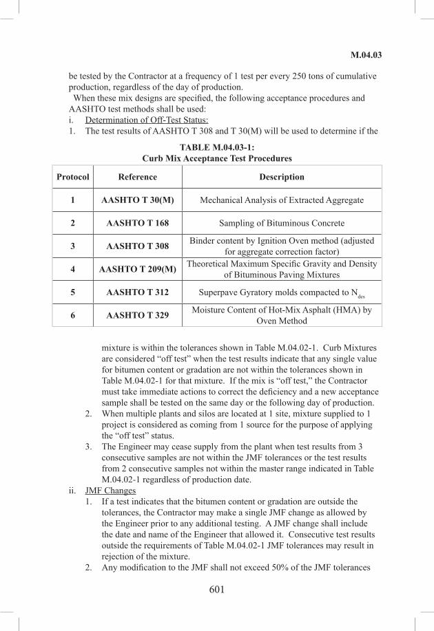
601
M.04.03
be tested by the Contractor at a frequency of 1 test per every 250 tons of cumulative production, regardless of the day of production. When these mix designs are specified, the following acceptance procedures and AASHTO test methods shall be used:i. Determination of Off-Test Status:1. The test results of AASHTO T 308 and T 30(M) will be used to determine if the
TABLE M.04.03‑1:Curb Mix Acceptance Test Procedures
Protocol Reference Description
1 AASHTO T 30(M) Mechanical Analysis of Extracted Aggregate
2 AASHTO T 168 Sampling of Bituminous Concrete
3 AASHTO T 308 Binder content by Ignition Oven method (adjusted for aggregate correction factor)
4 AASHTO T 209(M) Theoretical Maximum Specific Gravity and Density of Bituminous Paving Mixtures
5 AASHTO T 312 Superpave Gyratory molds compacted to Ndes
6 AASHTO T 329 Moisture Content of Hot-Mix Asphalt (HMA) by Oven Method
mixture is within the tolerances shown in Table M.04.02-1. Curb Mixtures are considered “off test” when the test results indicate that any single value for bitumen content or gradation are not within the tolerances shown in Table M.04.02-1 for that mixture. If the mix is “off test,” the Contractor must take immediate actions to correct the deficiency and a new acceptance sample shall be tested on the same day or the following day of production.
2. When multiple plants and silos are located at 1 site, mixture supplied to 1 project is considered as coming from 1 source for the purpose of applying the “off test” status.
3. The Engineer may cease supply from the plant when test results from 3 consecutive samples are not within the JMF tolerances or the test results from 2 consecutive samples not within the master range indicated in Table M.04.02-1 regardless of production date.
ii. JMF Changes1. If a test indicates that the bitumen content or gradation are outside the
tolerances, the Contractor may make a single JMF change as allowed by the Engineer prior to any additional testing. A JMF change shall include the date and name of the Engineer that allowed it. Consecutive test results outside the requirements of Table M.04.02-1 JMF tolerances may result in rejection of the mixture.
2. Any modification to the JMF shall not exceed 50% of the JMF tolerances

602
M.04.03
indicated in Table M.04.02-1 for any given component of the mixture without approval of the Engineer. When such an adjustment is made to the bitumen, the corresponding production percentage of bitumen shall be revised accordingly.
(c) Superpave Mix Acceptance Sampling and Testing Procedures: The hauling vehicle from which samples are obtained shall be selected using stratified – random sampling based on the total estimated tons of production in accordance with ASTM D3665, except that the first test shall be randomly taken from the first 151 tons or as directed by the Engineer. The Engineer may request a second acceptance test within the first sub lot. One (1) acceptance test shall always be performed in the last sub-lot based on actual tons of material produced. The number of sub lots per acceptance test is based on the total production per day as indicated in Table M.04.03-2. Quantities of the same type and level mix per plant may be combined daily for multiple State projects to determine the number of sub lots. The Engineer may direct that additional acceptance samples be obtained to represent materials actually being delivered to the Project. The payment adjustment for air voids and liquid binder will be calculated per sub lot as described in Section 4.06. An acceptance test shall not be performed within 150 tons of production from a previous acceptance test unless approved by the Engineer. Quality Control tests are not subject to this restriction. Unless otherwise tested, a minimum of 1 acceptance test shall be performed for every 4 days of production at a facility for each type and level mix (days of production may or may not be consecutive days).
TABLE M.04.03‑2:Superpave Acceptance Testing Frequency
per Type/Level/Plant
Daily quantity produced in tons (lot) Number of Sub Lots/Tests
0 to 150 0, Unless requested by the Engineer
151 to 600 1
601 to 1,200 2
1,201 to 1,800 3
1,801 or greater 1 per 600 tons or portions thereof
When the Superpave mix design is specified, the following acceptance and AASHTO test procedures shall be used:

603
M.04.03
TABLE M.04.03‑3:Superpave Acceptance Testing Procedures
Protocol Reference Description
1 AASHTO T 168 Sampling of bituminous concrete
2 AASHTO R 47 Reducing samples to testing size
3 AASHTO T 308 Binder content by Ignition Oven method (adjusted for aggregate correction factor)
4 AASHTO T 30 Gradation of extracted aggregate for bituminous concrete mixture
5 AASHTO T 312 (1)Superpave Gyratory molds compacted to Ndes
6 AASHTO T 166 (2)Bulk specific gravity of bituminous concrete
7 AASHTO R 35 (2)Air voids, VMA
8 AASHTO T 209(M) Maximum specific gravity of bituminous concrete (average of two tests)
9 AASHTO T 329 Moisture content of Production bituminous concrete
Notes: (1) One (1) set equals 2 each of 6-in molds. Molds to be compacted to Nmax for PPTs and to Ndes for production testing. The first sublot of the year shall be compacted to Nmax(2) Average value of 1 set of 6-in molds.
If the average corrected Pb content differs by 0.3% or more from the average bituminous concrete facility production delivery ticket in 5 consecutive tests regardless of the production date (moving average), the Contractor shall immediately investigate, determine an assignable cause and correct the issue. When 2 consecutive moving average differences are 0.3% or more, the Engineer may require a new aggregate correction factor. The test specimen must be ready to be placed in an approved ignition furnace for testing in accordance with AASHTO T 308 within 30 minutes of being obtained from the hauling vehicle and the test shall start immediately after. The Contractor shall perform moisture susceptibility (TSR) testing annually for all design levels of HMA-, WMA-, and PMA- S0.5 plant-produced mixtures, in accordance with the latest version of AASHTO T 283(M). If any material source changes from the previous year, or during the production season, a mix design TSR as well as a production TSR is required for the new mixture. The AASHTO T 283(M) test shall be performed at an AMRL by NETTCP Certified Technicians. The test results and specimens shall be submitted to the Engineer for review. This shall be completed within 30 days from the start of production. Superpave

604
M.04.03
mixtures that require anti-strip additives (either liquid or mineral) shall continue to meet all requirements specified herein for binder and bituminous concrete. The Contractor shall submit the name, manufacturer, percent used, technical datasheet and SDS for the anti-strip additive (if applicable) to the Engineer. In addition, compaction of samples shall be accomplished utilizing an accepted Superpave Gyratory Compactor (SGC), supplied by the Contractor. The SGC shall be located at the facility supplying mixture to the Project.
i. Determination of Off-Test Status:1. Superpave mixes shall be considered “off test” when any Control Point
Sieve, VA, VMA, and Gmm values are outside of the limits specified in Table M.04.03-4 and the computed binder content (Pb) established by AASHTO T308 or as documented on the vehicle delivery ticket is below the minimum binder content stated in Table M.04.02-5. Note that further testing of samples or portions of samples not initially tested for this purpose cannot be used to change the status.
2. Any time the bituminous concrete mixture is considered Off-test:A. The Contractor shall notify the Engineer (and project staff) when the
plant is “off test” for a type of mixture. When multiple plants and silos are located at one site, mixture supplied to one project is considered as coming from one source for the purpose of applying the “off test” determination.
B. The Contractor must take immediate actions to correct the deficiency, minimize “off test” production to the project, and obtain an additional Process Control (PC) test after any corrective action to verify production is in conformance to the specifications. A PC test will not be used for acceptance and is solely for the use of the Contractor in its quality control process.
ii. Cessation of Supply for Superpave Mixtures with no Payment Adjustment: Production of bituminous concrete shall cease for the Project from any plant that consistently fails to produce mixture that meets the JMF and volumetric properties. The quantity of Superpave mixtures shipped to the Project that is “off-test” will not be adjusted for deficient mixtures. The Contractor shall cease to supply mixture from a plant when:1. Bituminous concrete mixture is “off test” on 3 consecutive tests for any
combination of VMA or Gmm, regardless of date of production.2. Bituminous concrete mixture is “off test” on 2 consecutive tests for the
Control Point sieves in 1 day’s production. Following cessation, the Contractor shall immediately make necessary material or process corrections and run a Pre-Production Trial (PPT) for that type of mixture. Use of that type of mixture from that plant will be prohibited on the Project until the Contractor has demonstrated the ability to produce acceptable mixture from that facility. When the Contractor has a passing test and has received approval from the Engineer, the use of that mixture to the Project may resume.
iii. Cessation of Supply for Superpave Mixtures with Payment Adjustment: Production of bituminous concrete shall cease for the Project from any plant
605
M.04.03
that consistently fails to produce mixture that meets the Superpave minimum binder content by mix type and level listed in Table M.04.02-5. The quantity of Superpave mixtures shipped to the project that is “off-test” will be adjusted for deficient mixtures in accordance with Section 4.06. The Contractor shall cease to supply mixture from a plant when:1. The binder content (Pb) is below the requirements of Table M.04.02-5 on
the ignition oven test result after 2 consecutive tests, regardless of the date of production.
2. The air voids (VA) is outside the requirements of Table M.04.03-4 after 3 consecutive tests, regardless of the date of production.
Following cessation, the Contractor shall immediately make necessary material or process corrections and run a Pre-Production Trial (PPT) for that type of mixture. Use of that type of mixture from that plant will be prohibited on the Project until the Contractor has demonstrated the ability to produce acceptable mixture from that facility. When the Contractor has a passing test and has received approval from the Engineer, the use of that mixture to the Project may resume.
iv. JMF Changes for Superpave Mixture Production: It is understood that a JMF change is effective from the time it was submitted forward and is not retroactive to the previous test or tests. JMF changes are permitted to allow for trends in aggregate and mix properties but every effort shall be employed by the Contractor to minimize this, to ensure a uniform and dense pavement. A revised JMF submittal shall include the date and name of the Engineer that allowed it. JMF changes are only permitted prior to or after a production shift for all bituminous-concrete types of mixtures and only when they:1. Are requested in writing and pre-approved by the Engineer.2. Are based on a minimum of 2 successful tests.3. Are documented with a promptly submitted revised JMF on the form
provided by the Engineer.4. A revised JMF submittal shall include the date and name of the Engineer
that allowed it. No change will be made on any aggregate or RAP consensus property or specific gravity unless the test is performed at an AASHTO Materials Reference Laboratory (AMRL) by NETTCP Certified Technicians. A JMF change shall be submitted every time the plant target RAP or bin percentage deviates by more than 5% or the plant target binder content deviates by more than 0.15% from the active JMF.

606
M.04.03
TABLE M.04.03‑4: Superpave Master Range forBituminous Concrete Mixture Production
S0.25 S0.375 S0.5 S1 Tolerances
Sieve ControlPoints(4)
ControlPoints(4)
ControlPoints(4)
ControlPoints(4)
From JMFTargets(4)
inches Min (%)
Max (%)
Min (%)
Max (%)
Min (%)
Max (%)
Min (%)
Max (%) +/- Tolerance
1.5 - - - - - - 100 -1.0 - - - - - - 90 1003/4 - - - - 100 - - 901/2 100 - 100 - 90 100 - -3/8 97 100 90 100 - 90 - -
No. 4 - 90 - 90 - - - -No. 8 32 67 32 67 28 58 19 45No. 16 - - - - - - - -No. 200 2.0 10.0 2.0 10.0 2.0 10.0 1.0 7.0
Pb(2) - - - - - - - - see note (2)
VMA (%) 16.0 16.0 15.0 13.0 1.0VA (%) 4.0 4.0 4.0 4.0 1.0Gmm JMF value JMF value JMF value JMF value 0.030
Agg. Temp.(5) 280 - 350° F 280 - 350° F 280 - 350° F 280 - 350° FMix Temp.(6) 265-325°F (1) 265-325°F (1) 265-325°F (1) 265-325°F (1)
Prod. TSR N/A N/A ≥80% N/A
T-283Stripping N/A N/A
Minimal as determined by the Engineer
N/A
Notes: (1) 300° F minimum after October 15. (2) Minimum Pb as specified in Table M.04.02-5. (3) Control point range is also defined as the master range for that mix. (4) JMF tolerances shall be defined as the limits for production compliance. VA & Pb payment is subject to adjustments, as defined in Subarticle 4.06.04-2. (5) For WMA, lower minimum aggregate temperature will require Engineer’s approval. (6) For WMA or polymer modified asphalt, the mix temperature shall meet manufacturer’s recommendations. In addition for WMA the maximum mix temperature shall not exceed 325° F once the WMA technology is incorporated.

607
M.04.03
TABLE M.04.03‑5:JMF Tolerances for Application
of Positive AdjustmentsSieve Tolerances
From JMFTargets
inches ±Tolerance3/4 9 (1)
1/2 9 (1)
3/8 9 (2)
No. 4 8No. 8 7No. 16 6No. 200 3
Pb 0.4Notes:(1) Only for S1 mixes(2) Only for S0.5 and S1 mixes
TABLE M.04.03‑6:Superpave Master Range for Traffic Levels
and Design Volumetric Properties
TrafficLevel
Design ESALsNumber of Gyrations by
Superpave Gyratory Compactor
(million) Nini Ndes 1* < 0.3 6 502 0.3 to < 3.0 7 753 ≥3.0 8 100
* NOTE: Level 1 for use by Towns and Municipalities ONLY.

608
M.04.03
TABLE M.04.03‑7:Modifications to Standard AASHTO
and ASTM Test Specifications and Procedures
AASHTO Standard Specification
Reference Modification
M 140
Emulsified Asphalt grade RS-1H shall meet all the requirements of the emulsified asphalt grade RS-1 except for the penetration requirement of the residue that will change from 100 to 200 penetration units to 40 to 90 penetration units (0.1 mm).
AASHTO Standard Method of Test
Reference Modification
T 30 Section 7.2 through 7.4 - Samples are not routinely washed for production testing
T 168 Samples are taken at 1 point in the pile. Samples from a hauling vehicle are taken from only 1 point instead of 3 as specified.Selection of Samples: Sampling is equally as important as the testing, and the sampler shall use every precaution to obtain samples that are truly representative of the bituminous mixture.Box Samples: In order to enhance the rate of processing samples taken in the field by Construction or Maintenance personnel, the samples will be tested in the order received and data processed to determine conformance to material specifications and to prioritize inspections by laboratory personnel.
T 195 Section 4.3 only 1 truckload of mixture is sampled. Samples are taken from opposite sides of the load.
T 209Section 7.2 - The average of 2 bowls is used proportionally in order to satisfy minimum mass requirements.8.3 - Omit Pycnometer method.
T 283
When foaming technology is used, the material used for the fabrication of the specimens shall be cooled to room temperature, and then reheated to the manufacturer’s recommended compaction temperature prior to fabrication of the specimens.
T 331 6.1 Cores are dried to a constant mass prior to testing using a core-dry machine.

609
M.04.03
TABLE M.04.03‑7 (continued):Modifications to Standard AASHTO
and ASTM Test Specifications and Procedures
AASHTO Standard Recommended Practices
Reference Modification
R 26
Quality Control Plans must be formatted in accordance with AASHTO R 26, certifying suppliers of performance-graded asphalt binders, Section 9.0, Suppliers Quality Control Plan, and “NEAUPG Model PGAB QC Plan.”
1. The Department requires that all laboratory technician(s) responsible for testing PG-binders be certified or Interim Qualified by NETTCP as a PG Asphalt Binder Lab Technician.
2. Sampling of asphalt binders shall be done under the supervision of qualified technician. NECTP “Manual of Practice,” Chapter 2 Page 2-4 (Key Issues 1-8).
3. A copy of the Manual of Practice for testing asphalt binders in accordance with the Superpave PG Grading system shall be in the testing laboratory.
4. All laboratories testing binders for the Department are required to be accredited by the AAMRL.
5. Sources interested in being approved to supply PG-binders to the Department by use of an “in-line blending system,” must record properties of blended material, and additives used.
6. Each source of supply of PG-binder must indicate that the binders contain no additives used to modify or enhance their performance properties. Binders that are manufactured using additives, modifiers, extenders, etc., shall disclose the type of additive, percentage and any handling specifications or limitations required.
7. All AASHTO M 320 references shall be replaced with AASHTO M 332.
8. Each year, in April and September, the supplier shall submit test results for 2 BBR testing at 2 different temperatures in accordance with AASHTO R 29.
Suppliers shall provide AASHTO M 332 testing results and split samples at a minimum of 1 per lot.

610
NOTES

611
M.05.01
SECTION M.05PROCESSED AGGREGATE BASE ANDPAVEMENT SURFACE TREATMENT
M.05.01—Processed Aggregate Base and PavementM.05.02—Surface Treatment
M.05.01—Processed Aggregate Base and Pavement: The materials for this work shall meet the following requirements: 1. Gradation: Coarse and fine aggregates shall be combined and mixed by approved methods so that the resulting material shall meet the following gradation requirements:
Square Mesh Sieves Percent Passing by WeightPass 1 1/2 inches 100
Pass 2 inches 95-100Pass 3/4 inch 50-75Pass 1/4 inch 25-45Pass No. 40 5-20Pass No. 100 2-12
2. Coarse Aggregate: Coarse aggregate shall be either gravel, broken stone or reclaimed miscellaneous aggregate containing no more than 2% by weight of asphalt cement, at the option of the Contractor. When tested by means of the Los Angeles Machine, using AASHTO Method T 96, the coarse aggregate shall not have a loss of more than 50%.(a) If gravel is used for the coarse aggregate, it shall consist of sound, tough, durable
particles of crushed or uncrushed gravel or a mixture thereof, free from soft, thin, elongated or laminated pieces, lumps of clay, loam and vegetable or other deleterious substances.
(b) If broken stone is used for the coarse aggregate, it shall consist of sound, tough, durable fragments of rock of uniform quality throughout. It shall be free from soft disintegrated pieces, mud, dirt, organic or other injurious material.
(c) If the reclaimed miscellaneous aggregate is used for the coarse aggregate, it shall consist of sound, tough, durable fragments of uniform quality throughout. It shall be free from soft disintegrated pieces, mud, dirt, glass, organic or other injurious material.
(d) Soundness for Gravel, Broken Stone and Reclaimed Miscellaneous Aggregate: When tested by magnesium sulfate solution for soundness using AASHTO Method T 104, the coarse aggregate shall show a loss of not more than 15% at the end of 5 cycles.
3. Fine Aggregate: The fine aggregate shall be natural sand, stone sand, screenings or any combination thereof. The fine aggregate shall be limited to material 95% of which passes a No. 4 sieve having square openings and not more than 8% of which passes a No. 200 sieve. The material shall be free from clay, loam and deleterious materials.(a) Plasticity: When natural sand is used, the fine aggregate shall conform to the
requirements of Article M.02.06-2.(b) Plasticity: When screenings or any combination of screenings and natural

612
M.05.02
sand or any combination of stone sand and natural sand are used, the following requirements shall apply:
1. When the fraction of the dry sample passing the No. 100 mesh sieve is 6% or less by weight, no plastic limit test will be made.
2. When the fraction of the dry sample passing the No. 100 mesh sieve is greater than 6% and not greater than 10% by mass, that fraction shall not have sufficient plasticity to permit the performing of the plastic limit test, using AASHTO Method T 90.
3. When the fraction of the dry sample passing the No. 100 mesh sieve is greater than 10% by weight, the sample shall be washed; and additional material passing the No. 100 mesh sieve shall be determined by AASHTO Method T 146, except that the No. 100 mesh sieve shall be substituted for the No. 40 mesh sieve where the latter is specified in AASHTO Method T 146. The combined materials that have passed the No. 100 mesh sieve shall not have sufficient plasticity to permit the performing of the plastic limit test using AASHTO Method T 90.
M.05.02—Surface Treatment: Materials for this work shall meet the following requirements: 1. Bituminous Material: The Bituminous materials shall meet the requirements of Section M.04. The Asphalt Emulsion grade shall be as specified in the Contract or as directed by the Engineer. The type of bituminous material to be used, as well as its viscosity or grade, will depend upon the character and condition of the surface to be treated, the season of the year at which the work is to be done, and will be determined by the Engineer. The Contractor shall not order any material for this work until it has obtained definite instructions from the Engineer as to the asphalt emulsion that is required and as to the type of the bituminous material selected. 2. Sand Cover: Sand shall contain no more than 3% inorganic silt and clay by actual dry weight, using AASHTO Method T 11 and shall meet the following gradation requirements:
Square Mesh Sieves Percent Passing by WeightPass 1/2 inch 100Pass 3/8 inch 95-100
Pass No. 4 80-100Pass No. 50 10-30Pass No. 100 0-10

613
NOTES

614
M.06.01
SECTION M.06 METALS
M.06.01—Reinforcing SteelM.06.02—Structural Steel and Other Structural MaterialsM.06.03—GalvanizingM.06.04—Filler Metal for Welding
M.06.01—Reinforcing Steel: The materials for this work shall meet the following requirements: 1. Bar Reinforcement: Bar reinforcement shall be deformed and conform to the following: Uncoated bar reinforcement shall meet the requirements of ASTM A615, Grade 60. Epoxy coated bar reinforcement shall meet the requirements of ASTM A615, Grade 60 and shall be epoxy coated in accordance with ASTM A775. All field repairs of the epoxy coating shall meet the requirements of ASTM D3963. Galvanized bar reinforcement shall meet the requirements of ASTM A615, Grade 60 and be galvanized, after fabrication, to the requirements of ASTM A767, Class 1, including supplemental requirements. Dowels and tie bars for masonry facing and for granite curbing shall be galvanized, after fabrication, in accordance with ASTM A767, Class 1. Weldable bar reinforcement shall meet the requirements of ASTM A706. Prior to incorporation into the work, samples of the uncoated, epoxy coated, galvanized and weldable bar reinforcement shall be submitted to the Engineer for destructive testing in accordance with the latest edition of the “Schedule of Minimum Requirements for Sampling Materials for Test.” One (1) sample, at least 60 in long, shall be submitted for each size, source of supply, and type of bar reinforcement. 2. Unit Weights: Listed below are the bar sizes with approximate weights, diameters, areas and perimeters.*
Bar Designation No.** Nominal Weight lb./ft.
DiameterIn.
Cross Sectional Area in2
Perimeterin
3 0.376 0.375 0.11 1.1784 0.668 0.500 0.20 1.5715 1.043 0.625 0.31 1.9636 1.502 0.750 0.44 2.3567 2.044 0.875 0.60 2.7498 2.670 1.000 0.79 3.1429 3.400 1.128 1.00 3.54410 4.303 1.270 1.27 3.99011 5.313 1.410 1.56 4.43014 7.65 1.693 2.25 5.3218 13.60 2.257 4.00 7.09
* Nominal dimensions of deformed bars are equivalent to those of plain round bars having the same weight (pounds per foot) as deformed bars. ** Bar numbers are based on the number of eighths of an inch included in the nominal diameter of the bars.

615
M.06.02
3. Wire and Welded Steel Wire Fabric: Wire shall be cold-drawn steel wire meeting the requirements of ASTM A82 (AASHTO M 32). Welded steel wire fabric, when used as reinforcement in concrete, shall meet the requirements of ASTM A185 (AASHTO M 55). The type of welded steel wire fabric shall be approved by the Engineer. 4. Bar Mat Reinforcement: Bar mat reinforcement shall conform to the requirements of ASTM A184 (AASHTO M 54) 5. Dowel Bar Mechanical Connections: Dowel bar mechanical connections shall develop in tension and compression at least 125% of the specified yield strength of the bar reinforcement being spliced. Epoxy coated mechanical connectors shall be epoxy coated in accordance with the requirements of ASTM D3963. Galvanized mechanical connectors shall be galvanized, after fabrication, in accordance with the requirements of ASTM A767, Class 1, including supplemental requirements. Prior to incorporation into the work, samples of the uncoated, epoxy coated and galvanized dowel bar mechanical connections shall be submitted to the Engineer for destructive testing. One (1) sample, complete with all the components, shall be submitted for each size, type and manufacturer of the dowel bar mechanical connections. 6. Deformed Steel Wire and Welded Deformed Steel Wire Fabric: Deformed steel wire shall be cold-worked, deformed steel wire meeting the requirements of AASHTO M 225 (ASTM A496). Welded deformed steel wire fabric, when used as reinforcement in concrete, shall meet the requirements of AASHTO M 221 (ASTM A497). The type of welded deformed steel wire fabric shall be approved by the Engineer. 7. Reinforcing Steel for Pavement: Reinforcing steel for pavement shall be in accordance with the applicable standard plans. 8. Reports and Certification: Mill test reports and materials certification shall be submitted for all types of reinforcing steel and dowel bar mechanical connections confirming they meet the requirements of the applicable specifications. Materials Certificates shall be submitted in accordance with Article 1.06.07 for all types of reinforcing steel and dowel bar mechanical connections.
M.06.02—Structural Steel: The materials for this work shall conform to the following requirements: 1. Structural Steel: Structural steel for bridges shall correspond to the designation shown on the plans. Unless otherwise indicated in the plans or specifications, structural steel for non-bridge related members or components shall conform to ASTM A709, Grade 36. All surfaces of steel plates and shapes used in the fabrication of bridge girders shall be blast cleaned and visually inspected by the Contractor prior to any fabrication or preparation for fabrication. Blast cleaning shall conform to the requirements of SSPC-SP-6-Commercial Blast. All steel plates and shapes used in the fabrication of bridge girders shall be substantially free from pitting and gouges, regardless of the cause. Substantially free is defined as:(a) The measured surface area of all pits and gouges regardless of depth represent less than
1% of the surface area of the plate or shape.(b) No pit or gouge greater than 1/32 in deep.(c) No pit or gouge closer than 6 in from another.

616
M.06.02
Any repair of plates or shapes will be performed in accordance with ASTM A6. 2. Anchor Bolts: Unless otherwise designated on the plans, anchor bolts, including suitable nuts and washers, shall conform to the following requirements:(a) Anchor bolt assemblies shall conform to the requirements of ASTM F1554, Grade 36.
All components of the bolt assembly shall be galvanized in conformance with ASTM A153.
(b) Certified Test Reports and Material Samples: The Contractor shall submit notarized copies of Certified Test Reports in conformance with Article 1.06.07. Prior to incorporation into the work, the Contractor shall submit samples of the anchor bolt assemblies to the Engineer for testing in accordance with the latest edition of the “Schedule of Minimum Requirements for Acceptance Testing.” One (1) sample shall be submitted for each diameter, material designation, grade or coating of anchor bolt assembly.
3. High Strength Bolts: High strength bolts, including suitable nuts and hardened washers, shall conform to the following requirements:(a) High strength bolts shall conform to ASTM A325 or ASTM A490 as shown on the
plans. High-strength bolts used with coated steel shall be mechanically galvanized, unless otherwise specified. High-strength bolts used with uncoated weathering grades of steel shall be Type 3. Nuts for ASTM A325 bolts shall conform to ASTM A563, grades DH, DH3, C, C3 and D. Where galvanized high-strength bolts are used, the nuts shall be galvanized, heat treated grade DH or DH3. Where Type 3 high-strength bolts are used, the nuts shall be grade C3 or DH3. Nuts for ASTM A490 bolts shall meet the requirements of ASTM A563, grades DH and DH3. Where Type 3 high-strength bolts are used, the nuts shall be grade DH3. All galvanized nuts shall be lubricated with a lubricant containing a visible dye of any color that contrasts with the color of the galvanizing. Black bolts must be oily to the touch when delivered and installed. Circular flat and square or rectangular beveled, hardened steel washers shall conform to ASTM F436. Unless otherwise specified, galvanized washers shall be furnished when galvanized high-strength bolts are specified, and washers with atmospheric corrosion resistance and weathering characteristics shall be furnished when Type 3 high-strength bolts are specified. Compressible-washer-type direct tension indicator washers, used in conjunction with high strength bolts, shall conform to ASTM F959. Where galvanized high-strength bolts are used, the washers shall be galvanized in accordance with ASTM B695, Class 50. Where Type 3 high-strength bolts are used, the washers shall be galvanized in accordance with ASTM B695, Class 50 and coated with epoxy.
(b) Identifying Marks: ASTM A325 for bolts and the specifications referenced therein for nuts require that bolts and nuts manufactured to the specification be identified by specific markings on the top of the bolt head and on one face of the nut. Head markings must identify the grade by the symbol “A325”, the manufacturer and the type, if Type 2 or 3. Nut markings must identify the grade, the manufacturer and if Type 3, the type. Markings on direct tension indicators must identify the manufacturer and Type “325.” Other washer markings must

617
M.06.02
identify the manufacturer and if Type 3, the type. ASTM A490 for bolts, and the specifications referenced therein for nuts, require that bolts and nuts manufactured to the specifications be identified by specific markings on the top of the bolt head and on 1 face of the nut. Head markings must identify the grade by the symbol “A490,” the manufacturer and the type, if Type 2 or 3. Nut markings must identify the grade, the manufacturer and if Type 3, the type. Markings on direct tension indicators must identify the manufacturer and Type “490.” Other washer markings must identify the manufacturer and if Type 3, the type.
(c) Dimensions: Bolt and nuts dimensions shall conform to the requirements for Heavy Hexagon Structural Bolts and for Heavy Semi-Finished Hexagon Nuts given in ANSI Standard B18.2.1 and B18.2.2, respectively.
(d) Galvanized Bolts: Galvanized bolts shall conform to ASTM A325, Type 1. The bolts shall be hot-dip galvanized in accordance with ASTM A153, Class C or mechanically galvanized in accordance with ASTM B695, Class 50. Bolts, nuts, and washers of any assembly shall be galvanized by the same process. The nuts shall be overtapped to the minimum amount required for the fastener assembly, and shall be lubricated with a lubricant containing a visible dye so a visual check can be made for the lubricant at the time of field installation. Galvanized bolts shall be tension tested after galvanizing. ASTM A490 bolts shall not be galvanized.
(e) Test Requirements: The maximum hardness of A325 bolts 1 in or less in diameter shall be 33 HRC. Plain, ungalvanized nuts shall have a minimum hardness of 89 HRB. Proof load tests, in accordance with the requirements of ASTM F606 Method 1, shall be required for the bolts. Wedge tests of full-size bolts are required in accordance with Section 8.3 of ASTM A325. Galvanized bolts shall be wedge tested after galvanizing. Proof load tests of ASTM A563 are required for nuts. Proof load tests for nuts used with galvanized bolts shall be performed after galvanizing, overtapping and lubricating. Rotational-capacity tests are required and shall be performed on all plain or galvanized (after galvanizing) bolt, nut and washer assemblies by the manufacturer or distributor prior to shipping and by the Contractor at the Site. The thickness of galvanizing on bolts, nuts and washers shall be measured. On bolts, it shall be measured on the wrench flats or on top of the bolt head, and on nuts it shall be measured on the wrench flats.
(f) Certified Test Reports and Materials Certificates: The Contractor shall submit notarized copies of Certified Test Reports and Materials Certificates in conformance with Article 1.06.07 for fastener assemblies. In addition the Certified Test Reports and Materials Certificates shall include the following:1. Mill test reports shall indicate the place where the material was melted
and manufactured. 2. Test reports for proof load tests, wedge tests, and rotational-capacity
tests shall indicate where the tests were performed, date of tests, location of where the components were manufactured and lot numbers.
3. The test report for galvanized components shall indicate the thickness

618
M.06.03
of the galvanizing.(g) Material Samples: Prior to incorporation into the work, the Contractor shall submit
samples of the bolt assemblies to the Engineer for testing in accordance with the latest edition of the “Minimum Schedule for Acceptance Testing.” Samples shall be submitted for each diameter, length, material designation, grade, coating and manufacturer of bolt assembly.
4. Welded Stud Shear Connectors: (a) Materials: Stud shear connectors shall meet the requirements of ASTM A108,
cold-drawn bar, Grades 1015, 1018 or 1020, either semi- or fully-killed. If flux-retaining caps are used, the steel for the caps shall be of a low carbon grade suitable for welding and shall comply with ASTM A109. Stud shear connectors shall be of a design suitable for electrically end-welding to steel with automatically timed stud welding equipment. The studs shall be of the sizes and dimensions noted on the plans. Flux for welding shall be furnished with each stud, either attached to the end of the stud or combined with the arc shield for automatic application in the welding operation. Each stud shall be furnished with a disposable ferrule of sufficient strength to remain intact during the welding operation and not crumble or break; it shall not be detrimental to the weld or create excessive slag. Tensile properties, as determined by tests of bar stock after drawing or of finished studs, shall conform to the following requirements in which the yield strength is as determined by the 0.2% offset method:
Tensile strength (min.) 60,000 psiYield strength (min.) 50,000 psi
Elongation (min.) 20% in 2 inchesReduction of area (min.) 50%
(b) Test Methods: Tensile properties shall be determined in accordance with the applicable sections of ASTM A370. Tensile tests of finished studs shall be made on studs welded to test plates using a test fixture similar to that shown in Figure 7.2 of the current AASHTO/AWS D1.5 – Bridge Welding Code. If fracture occurs outside of the middle 1/2 of the gage length, the test shall be repeated.
(c) Finish: Finished studs shall be of uniform quality and condition, free from injurious laps, fins, seams, cracks, twists, bends or other injurious defects. Finish shall be as produced by cold-drawing, cold-rolling or machining.
(d) Certified Test Reports and Materials Certificates: The Contractor shall submit a certified copy of the in-plant quality control test report in conformance with Article 1.06.07. The Contractor shall submit a Materials Certificate in conformance with Article 1.06.07 for the welded studs.
(e) Sample Materials for Testing: Prior to incorporation into the work, the Contractor shall submit samples of the stud shear connectors to the Engineer for testing in accordance with the latest edition of the “Schedule of Minimum Requirements for Acceptance Testing.” One (1) sample shall be submitted for each diameter and length of welded stud.
M.06.03—Galvanizing: Unless otherwise specified on the plans or in the special

619
M.06.03
provisions, the zinc coating on all iron and steel materials, other than wire, shall meet the requirements of ASTM A123, or A153, whichever shall apply. When mechanical galvanizing is used it shall meet the requirements of ASTM B695, Class 50.
M.06.04—Filler Metal for Welding: Unless otherwise shown on the plans or as indicated in the special provisions, fill metal for welding shall meet the requirements of AWS. The fabricator shall note on the shop plans the electrode classification number and other identification references for the electrodes and flux proposed.

620
M.07.01
SECTION M.07PAINT
M.07.01—General for All Paints and EnamelsM.07.02—Coating Systems for Structural SteelM.07.03—VacantM.07.04—VacantM.07.05—VacantM.07.06—VacantM.07.07—VacantM.07.08—VacantM.07.09—VacantM.07.10—VacantM.07.11—VacantM.07.12—VacantM.07.13—VacantM.07.14—VacantM.07.15—VacantM.07.16—VacantM.07.17—VacantM.07.18—VacantM.07.19—VacantM.07.20—Waterborne Pavement Marking PaintM.07.21—Hot‑Applied Waterborne Pavement Marking PaintM.07.22—Epoxy Resin Pavement MarkingsM.07.23—VacantM.07.24—Preformed Black Line Mask Pavement Marking TapeM.07.25—Black Epoxy Resin Pavement MarkingsM.07.30—Glass Beads
M.07.01—General for All Paints and Enamels: 1. Paints and enamels shall consist of pigments of the required fineness and composition, ground in the required vehicle by a suitable grinding machine to the required fineness. All pigments, resins, oils, thinners and driers used shall be of the best quality, free from adulterants of any kind and shall meet the requirements of the specifications. Materials not definitely covered by specifications shall be of the best quality used for the purpose in good commercial practice. 2. Proportions: All proportions as specified in formulas are by weight unless otherwise specified. 3. Fineness: All pigments, except aluminum, unless otherwise specified, shall be so finely ground that 100% shall pass through a No. 200 sieve; and not less than 97 % shall pass through a No. 325 sieve. 4. Curdling, Livering, Leveling: No paint or enamel shall liver or curdle, and the pigment shall remain in suspension in a satisfactory manner. The enamel type paints shall level properly and not show brush marks. 5. Colors: All paints and enamels shall be matched to the Department’s standard shades. Color chips may be obtained at the DMT. 6. Time of Drying: All paints or enamels, unless otherwise specified, shall dry to the

621
M.07.13
full gloss in not more than 18 hours. 7. Weight per Gallon: The weight per gallon of all paints and enamels shall be determined at 77°F. 8. Shipping: All paints and enamels shall be shipped in strong metal containers, plainly marked with the name, net weight and volume of paint or enamel content. The manufacturer’s name, address, date and lot number shall be stenciled on every package. 9. Samples, Sampling, and Testing: When so requested in the Contract or by the Engineer, samples and certified analysis of all pigments, oils, resins, thinners, driers or paint furnished shall be supplied by the manufacturer within 10 days after request is madetherefor. Sampling and testing will be in accordance with ASTM, Federal Supply Service, or by methods on file in the DMT of the Department.
M.07.02—Coating Systems for Structural Steel: The coating system to be used shall be as outlined in the Contract and shall be selected from the NEPCOAT Specification Criteria for Protective Coatings. Color: The color of the topcoat shall be as noted on the plans (FS 595 Color Number). Packaging and Labeling of Coating Material: The container shall be designed to store the specific coating material. Each container of coating materials shall bear a label that clearly shows the name of the coating manufacturer, the name of the product, the lot and batch numbers, the date of manufacture and the shelf life expiration date. The label shall also include complete specific instructions for opening the container and for mixing, thinning, and applying the coating material contained therein. If the coating material cannot be positively identified from the label on the container, it shall not be used. Delivery: Coating material shall be furnished in the manufacturer’s original sealed and undamaged container. Control of Materials: For each coating material, a Certified Test Report and a Materials Certificate shall be submitted in conformance with Article 1.06.07. The Certified Test Report shall contain the data required in the Contract and NEPCOAT Acceptance Criteria for Protective Coatings, List A or B.
M.07.03—Vacant
M.07.04—Vacant
M.07.05—Vacant
M.07.06—Vacant
M.07.07—Vacant
M.07.08—Vacant
M.07.09—Vacant
M.07.10—Vacant
M.07.11—Vacant
M.07.12—Vacant
M.07.13—Vacant
M.07.14—Vacant

622
M.07.14
M.07.15—Vacant
M.07.16—Vacant
M.07.17—Vacant
M.07.18—Vacant
M.07.19—Vacant
M.07.20—Waterborne Pavement Marking Paint: This specification is for white and yellow waterborne pavement marking paint that is to be applied to bituminous concrete and Portland cement concrete pavements. This paint shall be capable of being applied with paint striping equipment that does not require heating above ambient temperatures. All requirements shall be as specified in Article M.07.21, except as follows: 1. Total nonvolatile shall not be less than 70% by weight 2. Pigment shall be 45 to 55% by weight 3. Weight per gallon shall not be less than 12.5 lb./gal. when tested in accordance with
ASTM D1475 4. Drying time to no pick up shall be 15 minutes or less when tested in accordance with
ASTM D711
M.07.21—Hot‑Applied Waterborne Pavement Marking Paint: This specification is for white and yellow fast-drying waterborne pavement marking paint to be applied to bituminous concrete and Portland cement concrete pavements. This paint shall be capable of being applied with paint striping equipment at an application temperature of 130 to 145°F. General: Specifications and publications that apply are as follows:• FS TT-P-1952 - Paint, Traffic and Air Field Marking, Waterborne • Federal Test Method Standard No. 141 - Paint, Varnish, Lacquer and Related
Materials, Methods of Inspection, Sampling and Testing • FS No. 595 – Colors
ASTM Standards: • D211 - Specifications for Chrome Yellow and Chrome Orange• D476 - Specifications for Titanium Dioxide Pigments• D562 - Test for Consistency of Paints Using the Stormer Viscometer• D869 - Test for 45-deg, 0-deg Directional Reflectance Factor of Opaque
Specimens by Broad Band Filter Reflectometry Detailed Requirements, Formulation and Manufacture: The paint shall be formulated and manufactured from first-grade raw materials and shall be free from defects and imperfections that might adversely affect the serviceability of the finished product. The materials shall not exhibit settling or jellying after storage in the sealed containers as received that will affect the performance of the products. The paint shall provide the proper anchorage, refraction and reflection for the finished glass spheres when applied as specified. Composition: The composition of the paint shall be at the discretion of the manufacturer, provided that the finished product meets the requirements of any applicable Federal, State or Local regulations for products of this type and the following requirements: 1. Paint shall not contain more than 0.06% lead

623
M.07.21
2 Total nonvolatile shall not be less than 76% by weight 3. Pigment shall be 58 to 63% by weight 4. Resin solids shall be composed of 100% acrylic emulsion polymer 5. Volatile organic compounds shall not exceed 1.25 lb./gal., excluding water 6. Closed-cup flash point shall not be less than 100°F, and weight per gallon shall not
be less than 12.5 lb./gal. when tested in accordance with ASTM D1475. Viscosity: The consistency of the paint shall not be less than 80, nor more than 90 Krebs units when tested in accordance with ASTM D562. The paint shall have good spraying characteristics when the material is heated to application temperature of 130°F to 145°F. Flexibility: The paint shall not show cracking or flaking when subjected to the TT-P-1952 flexibility test in which the panels used shall be tin plates that have an area of 3 in x 5 in and 35 - 31 U.S. Gauge in thickness. The tin panels shall be lightly buffed with steel wool and thoroughly cleaned with solvent before being used for tests. Dry Opacity: Both white and yellow paints shall have a minimum contrast ratio of 0.96. Contrast ratio shall be determined by applying a wet film thickness of 0.005 in to a standard hiding power chart. After drying, the black and white reflectance values shall be determined using a suitable reflectometer and the contrast ratio determined. Bleeding: The paints shall have a minimum bleeding ratio of 0.97 when tested in accordance with FS TT-P-1952. Abrasion Resistance: No less than 210 liters of sand shall be required to remove paint film when tested in accordance with TT-P-1952. Color: The paint shall not discolor in sunlight and shall maintain colorfastness throughout its life, approximately 2 years. Color determination shall be made without beads, after a minimum of 24 hours. Color for yellow paint shall be a visual match for 595-13538. If not a visual match, the diffuse day color of the paint shall conform to the CIE Chromaticity coordinate limits as follows:
x y x y x y x y BrightnessWhite 0.305 0.295 0.360 0.360 0.388 0.377 0.280 0.3l0 84.0 minYellow 0.485 0.455 0.506 0.452 0.484 0.428 0.477 0.438 50.0 min
Glass Bead Adhesion: The paint with glass beads conforming to M.07.30, applied at the rate of 6.0 lb./gal. of paint, shall require not less than 150 liters of sand to remove paint film and glass beads. Scrub Resistance: The paint shall pass 300 cycles minimum when tested in accordance with ASTM D2486. Drying Time: The reflectorized line shall dry to no pick up in 120 seconds or less when applied at the ratio provided for specified glass spheres to paint (the paint at 15+ 1 mil wet film thickness equivalent to 100-115 s.f./gal. and the glass spheres at the equivalent rate of 6.0 lb./gal). The paint shall be applied with equipment so as to have the paint at a temperature of 130°F to 145°F at the spray gun.
M.07.22—Epoxy Resin Pavement Markings: General Requirements: Standards: All standards herein are minimum standards.

624
M.07.22
Identification: Each container must bear a label with the following information thereon: Name and address of manufacturer, production batch number, date of manufacture, shipping point, grade name and/or identification number, type of material, number of gallons, Contract number, use intended, directions for application and formula. Improperly labeled samples and deliveries shall be rejected. Certification: The manufacturer shall forward to the DMT 2 - 1 quart samples for each lot number in accordance with Federal Test Method Standard No. 141, Method 1022. A certified test report by an independent testing laboratory shall accompany the samples, indicating that the material as specified has been tested in accordance with ASTM or ACI testing procedures noted in this specification. The certified test report shall indicate the results of testing for the criteria contained herein. Additionally, once per calendar year, a 1 quart sample of the hardener accompanied by a certified test report shall be forwarded by the manufacturer to the ConnDOT Division of Materials Testing, 280 West Street, Post Office Box 207, Rocky Hill, Connecticut 06067. This sample shall be labeled as required under Section 1.06.07. The manufacturer shall furnish certified test reports, in accordance with Section 1.06.07 for each batch delivered for application at the Project Site prior to the start of work. Detailed Requirements: (a) Epoxy Resin Material: The material shall be composed of epoxy resins and pigments only. (b) Composition:
WHITE (percent by weight) YELLOW (percent by weight)20% ± 2% Titanium Dioxide 25% ± 2% Chrome Yellow
(ASTM D476 Type III) (ASTM D211 Type III)80% ± 2% Epoxy Resins 75% ± 2% Epoxy Resins
(c) Color: The color of the white material shall be no darker or yellower than color chip 17778 of FS No. 595 of the latest issue, when the material is placed in a type EH weatherometer for a period of 500 hours and weathered according to ASTM G23. Any noticeable discoloration of the epoxy markings, either during or after application to the pavement surface, as determined by the Engineer, will be considered unacceptable. Any discolored areas shall be removed and the markings shall be reapplied in accordance with this specification. The color of the yellow shall be reasonably close to color chip 13538 of the Federal Standard No. 595 of the latest issue. (d) Adhesion Capabilities: When the adhesion of the material to Portland cement concrete (the concrete shall have a minimum of 300 psi tensile strength) is tested according to ACI 503R testing procedure, the failure of the system must take place in the concrete. The concrete shall be 90°F when the material is applied, after which the material shall be allowed to cure for 72 hours at 73°F ± 3.5°F. (e) Abrasion Resistance: When the abrasion resistance of the material is tested according to ASTM C501 with a CS-17 wheel under a load of 1000 grams for 1000 cycles, the wear index shall be no greater than 82. (The wear index is the mass in milligrams that is abraded from the sample under the test conditions.) (f) Hardness: The Type D durometer hardness of the material shall be not less than 75 nor more than 90 when tested according to ASTM D2240 after the material has cured for

625
M.07.24
72 hours at 73°F ± 3.5°F. (g) Tensile Strength: The tensile strength of the material, when tested according to ASTM D638, shall not be less than 6,000 psi after 72 hours cure at 73°F ± 3.5°F. (h) Compressive Strength: The compressive strength of the material, when tested according to ASTM D695, shall not be less than 12,000 psi after 72 hours cure at 73°F ± 3.5°F. (i) Shelf Life: The individual components shall not require mixing prior to use when stored for a period of 12 months. (j) Glass Beads: General Requirements – The beads shall be transparent, clean, colorless glass, smooth and spherically shaped, free of milkiness, pits, or excessive air bubbles and conform to the following specific requirements:
● Quality Assurance Control – The beads shall be segregated into maximum lots of 2,500 pounds and lot numbers shall be stamped onto each lot. Each lot shall be tested for gradation, rounds and embedment coating.
● Gradation – The glass spheres shall meet the following gradation requirements:
Grading “A” Grading “B”Sieve Size % Passing Sieve Size % Retained
No. 20 100 No. 10 0No. 30 80-95 No. 12 0-5No. 50 9-42 No. 14 5-20No. 80 0-10 No. 16 40-80
No. 18 10-40No. 20 0-5
Pan 0-2
• Roundness – The glass beads shall have a minimum of 80% rounds per screen for 2 highest sieve quantities and no more than 3% angular particles per screen for Grading “B.” The remaining sieve fractions shall typically be no less than 75% rounds.
• Refractive Index – The glass beads shall have a refractive index of 1.50 to 1.52.
M.07.23—Vacant
M.07.24—Preformed Black Line Mask Pavement Marking Tape: General Requirements: The preformed, patterned black line mask pavement marking tape shall consist of a matte black, non-reflective tape in widths or sizes sufficiently large to mask the existing markings which are to be temporarily covered. The patterned masking tape shall be pre-coated with a pressure sensitive adhesive and shall be capable of being adhered to existing markings, on bituminous concrete pavement or Portland cement concrete in accordance with the manufacturer’s instructions without the use of heat, solvents or other additional adhesives, and shall be immediately ready for traffic use after application. The Contractor shall identify equipment necessary for proper application and removal, and make recommendations for application that will assure effective product performance. The preformed, patterned black line masking pavement marking tape shall be

626
M.07.25
suitable for use for 1 year after the date of receipt when stored in accordance with the manufacturer’s recommendations. Detailed Requirements: (a) Composition: The non-reflective, patterned black line mask pavement marking tape shall not contain metallic foil and shall consist of a mixture of high quality polymeric materials, pigments and inorganic fillers distributed throughout its base cross-sectional area, with a matte black non-reflective top layer. The patterned surface shall have a minimum of 20% of the surface area raised and coated with non-skid particles. The channels between the raised areas shall be substantially free of particles. The film shall be pre-coated with a pressure sensitive adhesive. A non-metallic medium shall be incorporated to facilitate removal. (b) Skid Resistance: The surface of the patterned, non-reflective black line mask pavement marking tape shall provide an initial average skid resistance value of 60 British Pendulum Number when tested in accordance with ASTM E303. (c) Thickness: The patterned material, without adhesive, shall have a minimum thickness of 0.065 in at the thickest portion of the patterned cross-section and a minimum thickness of 0.02 in at the thinnest portion of the cross-section. (d) Adhesion: The black line mask pavement marking tape shall adhere to the pavement and existing pavement markings under climatic and traffic conditions normally encountered in the construction work zone. (e) Removability: The black line mask pavement marking tape shall be removable after its intended use, intact or in large pieces, manually, at temperatures above 40°F without the use of heat, solvents, grinding or sand or water blasting. The black line mask pavement marking tape shall be totally removed from existing markings that are adequately adhered to the pavement surface, without damage to the underlying markings.
M.07.25—Black Epoxy Resin Pavement Markings: Identification: Each container shall have a label affixed to it with the following information thereon: name and address of manufacturer, shipping point, grade production batch number, date of manufacture, grade name and/or identification number, type of material, number of gallons, Contract number, use intended, directions for application, and formula. Improperly labeled samples and deliveries shall be rejected. Certification: For each batch of black epoxy resin, Certified Test Reports conforming to Article 1.06.07 shall be submitted from an independent testing laboratory and approved by the Engineer, prior to installation on the Project. Detailed Requirements: (a) Epoxy Resin Material: The material shall be composed of epoxy resins and pigments only. (b) Composition:
Component Percent by WeightCarbon Black (ASTM D476 Type III) 7 ± 2
Talc 14 ± 2Epoxy Resins 79 ± 4

627
M.07.30
(c) Black Aggregate: The moisture resistant aggregate shall meet the gradation requirements as follows:
Sieve Size Percent RetainedNo. 20 23-38No. 50 58-74No. 270 1-6
Pan 0-0.5
The moisture resistant aggregate shall have a urethane coating. The aggregate shall be angular with no dry disbursement pigment allowed. (d) Adhesion: The black epoxy resin pavement marking material shall be formulated so as to adhere to the pavement and existing pavement markings under climatic and traffic conditions normally encountered in the construction work zone. (e) Abrasion Resistance: When the abrasion resistance of the material is tested according to ASTM D 4060 with a CS-17 wheel under a load of 1000 grams for 1000 cycles, the wear index shall be no greater than 82. (f) Hardness: The Type D durometer hardness of the material shall not be less than 75 nor more than 90 when tested according to ASTM D2240 after the material has cured for 72 hours at 73.5°F ± 3.5°F. (g) Compressive Strength: The compressive strength of the material, when tested according to ASTM D695, shall not be less than 12,000 psi after 72 hours cured at 73.5°F ± 3.5°F.
M.07.30—Glass Beads: The glass beads shall meet the requirements of AASHTO M 247, Type 1.
628
M.08.01
SECTION M.08DRAINAGE
M.08.01—PipeGeneralIron/Steel
1. Cast Iron Pipe 2. Coated Corrugated Metal Pipe and Coated Corrugated Metal Pipe Elbows 3. Perforated or Plain Coated Metal Pipe for Underdrains or Outlets 4. Coated Corrugated Metal Pipe Arches 5. Corrugated Structural Plates and Bolts 6. Metal Culvert Ends
Concrete 7. Reinforced Concrete Pipe 8. Reinforced Concrete Elliptical Pipe 9. Perforated Reinforced Concrete Pipe for Underdrains and Outlets 10. Slotted Drain Pipe 11. Reinforced Concrete Culvert EndsAluminum
12. Corrugated Aluminum Pipe 13. Corrugated Aluminum Pipe for Underdrains and Outlets 14. Corrugated Aluminum Pipe Arches
Sealers/Gaskets 15. Cold‑Applied Bituminous Sealer 16. Preformed Plastic Gaskets 17. Flexible, Watertight, Rubber‑Type GasketsPlastic 18. Corrugated Polyethylene Pipe 19. Geotextiles 20. Polyvinyl chloride Plastic Pipe 21. Polyvinyl chloride Gravity Pipe
M.08.02—Catch Basins, Manholes and Drop InletsM.08.03—Aggregates
M.08.01—Pipe: General The Contractor shall submit manufacturer’s material certifications for all metal and plastic pipes other than PVC, metal pipe-arches, metal fittings and metal coupling bands in accordance with Section 1.06.07. IRON/STEEL 1. Cast Iron Pipe: This material shall meet the requirements of AASHTO M 64 for Extra-Heavy Cast Iron Culvert Pipe. 2. Coated Corrugated Metal Pipe and Coated Corrugated Metal Pipe Elbows: This material shall meet the following requirements: Pipe fabricated from zinc-coated steel sheet and aluminum-coated (Type 2) steel sheet must meet AASHTO M 36, Type 1 or IR. Pipe fabricated from metallic-coated and polymer-precoated steel sheet must meet
629
M.08.01
AASHTO M 245, Type 1. Unless otherwise indicated on the plans, the corrugation size and sheet thickness shall meet the following dimensional requirements:
TABLE M.08.01‑1
Nominal Inside Diameter (inches) Corrugations
Minimum Specified SheetThickness (inches)
6 1 1/2” X 1/4” .0528, 10 1 1/2” X 1/4” .06412, 15, 18 & 21 2 2/3” X 1/2” .06424, 30 , 36 2 2/3” X 1/2” .079 42, 48 2 2/3” X 1/2” .10954, 60 3” X 1” or 5” X 1” .06466, 72 3” X 1” or 5” X 1” .07978, 84, 90, & 96 3” X 1” or 5” X 1” .109
Steel Aluminum
18, 24, 30 Helical Rib ¾” X ¾ “ X 7 ½” .064 .06036 Helical Rib ¾” X ¾ “ X 7 ½” .064 .075 42, 48 & 54 Helical Rib ¾” X ¾ “ X 7 ½” .079 .10560, 66, 72, 78, 84 Helical Rib ¾” X ¾ “ X 7 ½” .109 .135
Aluminum pipe sheet thickness may be 0.004 in less than specified in Table M.08.01-1 for 1 1/2-in x 1/4-in, 2 2/3-in x 1/2-in, and 3-in x 1-in or 5-in x 1-in corrugations. Helical Rib shall be as specified in Table M.08.01-1. Zinc coated steel pipe, fittings, and coupling bands shall be coated with bituminous material as specified in AASHTO M 190 Type C. Pipe, fittings and coupling bands fabricated from aluminum coated steel sheet (Type 2) do not require coating of bituminous material or paved invert. Metallic-coated and polymer-precoated steel pipe, fittings, and coupling bands shall be coated as specified in AASHTO M 246, Type B. The thicker polymeric coating shall be on the inside of the pipe. Only 1 type of coating will be allowed for any continuously connected run of pipe. If elongation of the pipe is required, it shall be done by the manufacturer. 3. Perforated or Plain Coated Metal Pipe for Underdrains or Outlets: This material shall meet the requirements of AASHTO M 36, Type III or AASHTO M 245, Type III. (a) Perforations: The minimum diameter of perforations after asphalt coating shall be 1/4 in. (b) Coating: All requirements of M.08.01-2 shall apply except that the minimum thickness of the bituminous coating on zinc coated steel pipe, fittings, and coupling bands pipe shall be 0.03 in, not 0.05 in.

630
M.08.01
4. Coated Corrugated Metal Pipe‑Arches: This material shall meet the requirements of AASHTO M 36, Type II, Type IIR or AASHTO M 245, Type II. All coating requirements of M.08.01-2 shall apply. Unless otherwise indicated on the plans, the corrugation size and sheet thickness shall meet the dimensional requirements in Table M.08.01-2. 5. Corrugated Structural Plates and Bolts: These plates and bolts are for use in the construction of metal pipe of the large diameter and for metal plate arches or pipe arches to be assembled in the field, and they shall meet the requirements of AASHTO M 167 for corrugated metal pipe. The dimensions of plates and details of fabrication shall meet the requirements of the manufacturer. Where the plans call for a heavier gage for the bottom of the pipe than for the remainder of the pipe circumference, the lower fourth of the circumference shall be the minimum width of the heavier gage material.
TABLE M.08.01‑2Pipe-Arch EquivalentDiameter (Inches) Corrugations
Minimum Sheet Thickness (Inches)
15, 18, 21 2 2/3” X 1/2” .06424, 30 2 2/3” X 1/2” .07936, 42, 48 2 2/3” X 1/2” .10954, 60 2 2/3” X 1/2” .13860, 66, 72 3” X 1” or 5” X 1” .07978, 84, 90, 96 3” X 1” or 5” X 1” .10918, 21, 24 Helical Rib ¾” X ¾” X 7 ½” .06430, 36 Helical Rib ¾” X ¾” X 7 ½” .07942, 48, 54, 60 Helical Rib ¾” X ¾” X 7 ½” .109
The coating shall meet the requirements of AASHTO M 243. 6. Metal Culvert End: The materials used in this work shall meet the pertinent requirements of Articles M.08.01-2 and M.08.01-4. Bolts and fittings shall meet the requirements of ASTM A 307 and shall be galvanized to meet the requirements of ASTM A 153. The units shall be coated as specified in Articles M.08.01-2, M.08.01-4 or M.08.01-5. Fabrication: These units shall be formed from a rectangular sheet of metal by cutting and bending to form the desired shape. Two (2) or more sheets may be fastened together by riveting or bolting so as to form a rectangular sheet of the required width. Skirt extensions and a top plate, as needed to complete the unit, shall be separately formed. Skirt extensions shall be riveted or bolted to the skirt. All edges which will be exposed above the surface of the ground shall be reinforced before forming the unit by either of the following means: (1) The edge shall be bent to form a semicircular roll with an exterior diameter of 1 in, as shown in the detail drawing on the plans.

631
M.08.01
(2) A split tube of 1 in outside diameter and not lighter than 14 gage, shall be slipped over a row of rivets spaced not more than 6 in apart, as shown in the detail drawing on the plans. One (1) corrugation, matching the corrugations of the pipe or pipe-arch to which the unit is to be attached, shall be formed in the unit to insure secure and accurate alignment. Attachment: The unit may be shop-riveted to a length of the appropriate pipe or pipe-arch, or may be field attached to the pipe or pipe arch by either of the other attachment systems shown on the plans, or by other means acceptable to the Engineer. If the unit is shop-riveted to a length of pipe or pipe-arch, this length shall be sufficient to permit proper use of standard coupling bands. CONCRETE 7. Reinforced Concrete Pipe: Unless otherwise specified, this pipe shall meet the requirements of AASHTO M 170, Class IV, as supplemented and modified by the following: (a) Reinforcement: In circular pipe, only circular reinforcement will be allowed. (b) Laps and Welds: The reinforcement shall be lapped not less than 2 in and welded with an electric welding machine. (c) Quality Assurance Testing: Circular and elliptical reinforced concrete pipe shall be tested by the three-edge bearing method prescribed in AASHTO T 280, except as follows: (1) Modified or special design pipe shall be tested to the 0.01-in load and the ultimate
load requirements as per AASHTO M 170 and M 207. (2) At the discretion of the Engineer, pipe of standard design, as specified in AASHTO
M 170 and M 207, may be tested to the 0.01-in requirement plus 10% additional load in lieu of ultimate load testing. Test pipe attaining a 0.01-in crack will not be acceptable for use on Department projects.
(3) Cores for absorption and determination of steel reinforcement shall be taken on a random basis as determined by the Engineer. The cores shall be at least 6 in diameter.
(d) Inspection: The pipe plant, materials, processes of manufacture and the finished pipe shall be subject to inspection and approval by the Department. The pipe manufacturer’s records related to component materials, production and shipment of pipe for Department use shall be made available to the Department on request. The equipment and labor necessary for inspection, sampling and testing as required by the Department shall be furnished by the pipe manufacturer. Test equipment shall be calibrated at least once each 12 months, or as directed by the Engineer. The plant cement and aggregate scales shall be inspected and sealed by the approved agency at least once every 12 months. (e) Preliminary Tests and Tests for Extended Deliveries: As directed by the Engineer, the Department shall select for test from the stock of any manufacturer proposing to supply pipe to the Department, 2 of each size pipe up through 30-in diameter and 1 of each size greater than 30-in diameter. These sample pipes shall be tested under Department supervision by the three-edge bearing method. For pipe that fails, it shall be necessary for the manufacturer to either physically isolate the rejected pipe at the plant or to provide some means to clearly indicate the unacceptability of the pipe. Either method shall be performed to the satisfaction of the Engineer. When production is resumed on

632
M.08.01
any size, wall thickness or class previously rejected, preliminary tests shall be required. If 95% of all pipe tested at a particular plant from the first of the calendar year to September 30 meet specifications, including both preliminary and extended tests, it will not be necessary to perform the Fall three-edge bearing tests at this plant. Use of compression tests on representative cylinders or cores to determine the compressive strength of the concrete incorporated into the pipe products will be at the discretion of the Engineer. (f) Shipping: Pipe shall not be shipped until it is at least 7 days old unless earlier shipment is authorized by the Engineer on the basis of tests. (g) Certification: Pipe will be accepted by the Department on the basis of manufacturer’s certification. The manufacturer shall certify each shipment of pipe on Department Form MAT-073(PC-1), “Certification of Precast Concrete Products.” Two (2) copies of this certification shall be furnished with the shipment to the Engineer at the Project Site. 8. Reinforced Concrete Elliptical Pipe: This pipe shall meet the requirements of AASHTO M 207, Class HE IV. Manufacturing and testing shall meet Subarticle M.08.01-7. 9. Perforated Reinforced Concrete Pipe for Underdrain and Outlets: This material shall meet the requirements of Subarticle M.08.01-7 and shall be slotted in accordance with AASHTO M 175, Type 2 or as shown on the plans. Pipe for outlets shall not be perforated. 10. Slotted Drain Pipe: The pipe shall be asphalt coated and shall be as specified in Subarticle M.08.01-2. Concrete shall be as specified in Article M.03.01, Class “A” or pavement type. Concrete shall be cured as specified in Section M.03. The inlet aperture shall be longitudinal on top of the pipe and may be continuous or intermittent. The opening in the pipe wall may be fabricated in the form of continuous bar risers and spacers or of intermittent cut-out segments with structural members supporting a continuous grating as indicated in the plans. End caps shall be as provided by the manufacturer. Elastomeric polymer sealer shall meet the physical requirements of ASTM D3406 and be accepted on manufacturer’s certification. The pipe shall be helically corrugated with a continuous welded or lock seam. Pipe ends shall have 2 rolled annular corrugations on each end for jointing. Bar Riser and Spacer Type: Riser assemblies shall be fabricated from structural steel, in accordance with the dimensions on the plans. The riser assemblies shall be hot dipped galvanized according to ASTM A123. The assemblies shall be welded to the corrugated pipe on each side of the riser at the location of the solid web spacers. The riser shall terminate 1 in from the ends of each pipe length to allow clearance for single bolt coupling bands. The ends of the riser shall be closed with a suitable welded plate where solid web spacers do not come to the ends of the riser. The maximum deviation from straight in both the vertical and horizontal plane of the riser assembly shall not exceed 3/4 in per 20-ft length. Continuous Grating Type: The cut-out pipe segments shall provide a 2-in wide slot of maximum length between the lock seams. The slot shall be left intact 1 in on each side of the lock seam and this material shall be utilized to fasten the reinforcing bar in place. A bent epoxy coated reinforcing bar shall cross the slotted opening on 6-in centers. The

633
M.08.01
reinforcing bar shall be an ASTM A615, No. 13 deformed bar epoxy coated with 7 mils of fusion bonded epoxy powder meeting the requirements of AASHTO M 284. Grating shall be furnished unless noted otherwise in the Contract. Grating and all bearing bars, cross bars, and bent connecting bars shall be welding quality, mild carbon steel meeting the requirements of ASTM A569 and to the dimensions shown on the plans. Tie down bolts shall be J-Type bolts, plated, ASTM A307 steel supplied with self-locking nuts. Concrete forms shall be of cellular foam plastic base, fabricated as an integral part of the pipe and reinforcing bar assembly. The form shall be capped with a thick wood or plastic cap resting on top of the foam plastic and reinforcing bar. The maximum deviation from straight in both the vertical and horizontal plane of the completed assembly shall not exceed 3/4 in per 20-ft length. All grating and hardware shall be galvanized as specified in Article M.06.03. Expansion joint filler shall be as specified in Section M.03. 11. Reinforced Concrete Culvert End: The barrel shall meet the requirements of AASHTO M 170, Class II, except that the three-edge bearing tests will not be required. The flare shall be of the same thickness and materials as the barrel, and shall have steel reinforcement equaling or exceeding the amount shown on the table for the pertinent size. Tongues and grooves shall be compatible with tongues and grooves of pipe meeting AASHTO M 170, Class IV. Air entrainment shall be added to these units so as to maintain 5 to 8% entrained air. ALUMINUM 12. Corrugated Aluminum Pipe: This pipe shall meet the requirements of AASHTO M 196 Type I or Type IR. Sheet thickness shall be as specified in Subarticle M.08.01-2. 13. Corrugated Aluminum Pipe for Underdrains and Outlets: This material shall meet the requirements of AASHTO M 196 Type III or Type IIIR. Sheet thickness shall be as specified in Subarticle M.08.01-2. Pipe for outlets shall not be perforated. 14. Corrugated Aluminum Pipe Arches: These pipe arches shall meet the requirements of AASHTO M 196 Type II or Type IIR. Sheet thickness shall be as specified in Subarticle M.08.01-4. SEALERS/GASKETS 15. Cold‑Applied Bituminous Sealer: This material, for use in sealing of joints in concrete pipes, shall be free of asbestos and shall meet the following requirements: It shall be of such consistency that it may be spread on the joints with a trowel when the temperature of the air is between -20° F and 100° F. The bituminous material shall adhere to the concrete pipe so as to make a watertight seal, and shall not flow, crack or become brittle when exposed to the atmosphere. Unless otherwise specified, sampling shall be done in accordance with AASHTO T 40. The bituminous sealer shall be delivered to the Project in suitable containers for handling and shall be sealed or otherwise protected from contamination. The container shall show the brand name, net mass or volume, and the requirements for application. 16. Preformed Plastic Gaskets: This material for use in sealing of joints in concrete pipe shall meet the requirements of ASTM C1478.

634
M.08.02
17. Flexible, Watertight, Rubber‑Type Gaskets: This material for use in sealing concrete pipe joints shall conform to the requirements of ASTM C443. PLASTIC 18. Corrugated Polyethylene Pipe: Corrugated Polyethylene Pipe, either corrugated interior surface (Type C) or smooth interior surface (Type S) without perforations or with perforations (Type CP or SP), shall meet the requirements of AASHTO M 252 or M 294. Type D pipe shall have a smooth interior surface braced circumferentially or spirally with projections or ribs joined to a smooth outer wall. Both surfaces shall be fused to, or be continuous with, the internal supports. Type D shall meet the requirements of AASHTO M 294. 19. Geotextiles: The geotextile shall be non-rotting, acid and alkali resistant and have sufficient strength and permeability for the purpose intended, including handling and backfilling operations. Fibers shall be low water absorbent. The fiber network must be dimensionally stable and resistant to delamination. The geotextile shall be free of any chemical treatment or coating that will reduce its permeability. The geotextile shall also be free of any flaws or defects which will alter its physical properties. Torn or punctured geotextiles shall not be used. For each specific use, only geotextiles that are already on the Connecticut Department of Transportation’s Qualified Products List for the geotextile type will be used. The Engineer reserves the right to reject any geotextile he deems unsatisfactory for a specific use. The brand name shall be labeled on the geotextile or the geotextile container. Geotextiles which are susceptible to damage from sunlight or heat shall be so identified by suitable warning information on the packaging material. Geotextiles susceptible to sunlight damage shall not be used in any installations where exposure to light will exceed 30 days, unless specifically authorized in writing by the Engineer. 20. Polyvinyl Chloride Plastic Pipe: The pipe shall conform to the requirements of ASTM D1785. Couplings and elbows shall conform to the requirements of ASTM D2466 or D2467. 21. Polyvinyl Chloride Gravity Pipe: This pipe shall conform to one of the following specifications: ASTM F789, ASTM F679 or ASTM F794.
M.08.02—Catch Basins, Manholes and Drop Inlets: The materials to be used in the construction shall conform to the following: 1. Brick for Catch Basins, Manholes or Drop Inlets: Brick for catch basins, manholes or drop inlets shall conform to the requirements of ASTM C32 except that the depth shall be 2 1/4 in, the width 3 5/8 in and the length 8 in, and except that the maximum water-absorption by 5-hour boiling shall not exceed the following limits: Average of 5 bricks 15% Individual brick 18% 2. Concrete Building Brick for Catch Basins, Manholes or Drop Inlets: Concrete building brick for catch basins, manholes or drop inlets shall conform to the requirements of ASTM C55, Grade S II. 3. Masonry Concrete Units for Catch Basins, Manholes or Drop Inlets: Masonry concrete units for catch basins, manholes or drop inlets shall conform to the requirements of ASTM C139. 4. Precast Units for Drainage Structures: Precast units for drainage structures may

635
M.08.02
be used except where particular conditions require building or casting in place. Fabrication plants shall have a quality control plan approved by the Division Chief of Materials Testing that is demonstrated to the satisfaction of the Engineer. The facility, the quality of materials, the process of fabrication and the finished precast units shall be subject to inspection by the Engineer. Precast manholes shall conform to the requirements of AASHTO M 199 (ASTM C478). Circular precast catch basins and drop inlets shall conform to AASHTO M 199 (ASTM C478) as supplemented below. Rectangular precast catch basins and drop inlets shall conform to ASTM C913 as supplemented below: All materials used for concrete shall conform to the requirements of Section M.03. The pertinent provisions of Article 6.01.03 shall apply except that the concrete shall contain 5.0% - 8.0% entrained air. Water-absorption of individual cores taken from precast units shall be not more than 7%. Reinforcement shall conform to the requirements of Article M.06.01. Suitable provision shall be made in casting the units for convenient handling of the completed casting, and additional reinforcement steel shall be provided to allow for such handling in the casting yard and during transportation and placement. Each completed unit shall be identified with the name of manufacturer and date of the concrete pour from which it was cast, either by casting this information into an exposed face of the unit or by suitable stencil. For each day’s production of precast units, the fabricator shall mold, cure and test standard cylinders, or cylinders compacted in a similar manner to the parent precast units, for the purpose of determining the compressive strength of the concrete incorporated into the precast units. Concrete used in molding the cylinders shall be representative of the concrete incorporated into the precast units during the production period. Cylinders shall be molded in accordance with AASHTO T 23, cured by the same method as the units they represent, and tested as prescribed in AASHTO T 22. The fabricator shall determine the air content of the concrete used in the day’s production of precast units by performing tests as prescribed in AASHTO T 152. The equipment and personnel necessary to perform the required testing shall be furnished by the fabricator and approved by the Engineer. All testing equipment shall be calibrated at least once each 12 months or as directed by the Engineer. The fabricator shall maintain records relative to the production, testing and shipment of precast units supplied to the Department. Said records shall be available to a representative of the Department upon his request. The Department may accept precast concrete units on the basis of fabricator’s certification. The fabricator shall certify each shipment of precast concrete units on Department Form MAT 314 (PC-1), “Certification of Precast Concrete Products.” Two (2) copies of this certification shall be furnished with the shipment to the Engineer at the Project Site. Precast units that are cracked, show evidence of honeycomb, or have over 10% of their surface area patched may be subject to rejection, even though meeting other requirements. 5. Metal for Drainage Structures: Metal for catch basins, drop inlet and manhole frames, extensions, covers, and gratings shall be cast iron, cast steel, structural steel or malleable iron conforming to the requirements of the plans. Covers and gratings shall bear uniformly on their supports.

636
M.08.03
Extensions shall be designed so that the existing manhole cover or catch basin grate, when set in place, will have substantially the same bearing, fit and load carrying capacity as in the existing frame. The extension shall be designed to fit into the original frame, resting specifically on the flange and rim area. The extension shall accept the existing cover or grate so that the cover or grate is seated firmly without movement. Ladder rungs for manholes shall conform to AASHTO M 199 (ASTM C478). Cast iron shall conform to the requirements of AASHTO M 105, Class 25 for the frames and Class 30 for grates. Cast steel shall conform to the requirements of ASTM A27, Grade optional, and shall be thoroughly annealed. Structural Steel shall conform to the requirements of ASTM A36, or A 283, Grade B or better, as to quality and details of fabrication, except that in the chemical composition of the steel, the 2/10 of 1% of copper may be omitted. Malleable iron shall conform to the requirements of ASTM A47, Grade 22010. The materials and method of manufacture for drop inlets shall conform to the requirements as stated on the plans or as ordered.
M.08.03—Aggregates 1. Bedding Material: Material for pipe bedding shall be sand or sandy soil, all of which passes a 3/8-in sieve, and not more than 10% passes a No. 200 sieve. When ground water is encountered, the Engineer may allow No. 6 stone conforming to Article M.01.01 to be used instead of sand or sandy soil. 2. Aggregates for Underdrains: Materials for filling the trench shall consist of well-graded, clean, non-plastic sands or well-graded, clean, durable broken stone or screened gravel. Unless otherwise noted, the type of material to be used shall be sand. Sand: This material shall meet the requirements of Subarticle M.03.01-2. Broken Stone or Screened Gravel: This material shall conform to the gradation requirements for Size No. 8 under Article M.01.01.

637
NOTES

638
M.09.01
SECTION M.09SHEET PILING AND PILES
M.09.01—Sheet PilingM.09.02—Piles
M.09.01—Sheet Piling: The materials for this work shall conform to the following requirements: 1. Timber Sheet Piling: The timber, unless otherwise definitely noted on the plans or in the special provisions, may consist of any species which will satisfactorily stand driving. It shall be sawn or hewn with square corners and shall be free from worm holes, loose knots, wind shakes, decayed or unsound portions, or other defects which might impair its strength or tightness. The piles shall be of the dimensions shown on the plans or as directed, either cut from the solid material or made by building up the piles of three planks securely fastened together. The piles shall be drift sharpened at their lower ends so as to wedge the adjacent piles tightly together. 2. Steel Sheet Piling: Steel sheet piles shall conform to the requirements of ASTM A328.
M.09.02—Piles: The materials for this work shall conform to the following requirements: 1. Untreated Timber Piles: Timber piles shall conform to the requirements of AASHTO M 168, as supplemented by the following requirements: All timber piles shall be cut from sound, live trees preferably during the winter season. Piles shall contain no unsound knots or other defects which may impair their strength and durability. All knots shall be trimmed close to the body of the piles. All measurements for piles shall be taken under the bark. Piles shall have the following minimum dimensions:
Pile Length Tip Dia. Inches Butt Dia. Inches 20 feet and under 8 11
21 to 40 feet 8 1241 to 60 feet 7 13Over 60 feet 6 15
2. Treated Timber Piles: The timber piles shall be pressure-treated with wood preservatives of creosote oil or creosote solution types. Piles shall comply with the requirements of Subarticle M.09.02-1 except that piles for treatment shall be Douglas fir, larch, Southern yellow pine, Norway pine or red oak. They shall be peeled of outer bark and inner skin soon after cutting so that the piles are smooth and clean. Piles shall contain as much sapwood as possible, and care shall be taken to minimize damage to the sapwood when peeling and cleaning the piles. After preparation, the minimum thickness of the sapwood ring at the butt end shall be 1 in, except for Southern yellow pine which shall have 1 1/2 in. Conditioning, treatment and wood preservative shall conform to the requirements of AASHTO M 133, except that creosote petroleum solution shall not be used for treatment of piles to be utilized in coastal waters.

639
M.09.02
The minimum net final retention of preservative per cubic foot of wood shall be as follows:
For piles to be used on land or in fresh water: 12 poundsFor piles to be used in brackish or salt water: Douglas fir and larch 14 poundsSouthern yellow pine 20 pounds Red oak (Full cell process) refusal
Prior to furnishing the treated piles, the Contractor shall submit certification of the species, grade or class of pile material, the grade of wood preservative used, and the final net retention of the preservative in pounds per cubic foot of wood. Treated piles shall be subject to inspection by the Engineer at the Site. No previous certifications or approval at the treatment plant shall bar rejection in the field for injury, breakage or defects in the piles prior to their installation. The use of “S” irons for repairing or preventing checks, splits or other defects will not be permitted. All treated timber piles shall be carefully handled and properly stored. Any surface breaks which do not warrant rejection shall be given 3 coats of hot creosote oil. The heads of piles shall be treated as follows: The sawed surface shall be thoroughly brush-coated with 3 successive applications of hot creosote, followed by a thick application of a mixture of 30% creosote and 70% pitch. The application of the pitch coat will not be required to pile heads encased in concrete. All bolt holes made in the pile subsequent to treatment shall be treated with creosoted oil by means of an approved pressure bolt hole treater. After being so treated, all unfilled holes shall be plugged with creosoted plugs. 3. Steel Piles: Piles shall be rolled steel sections of the mass and shape called for on the plans or specified by the Engineer. Piles, splice plates and points shall be new material meeting the requirements of ASTM A36. Stock Steel conforming to these requirements and free from surface imperfections will be accepted upon presentation of certified mill test reports as to the quality of the stock material and receipt of affidavit that the stock material furnished is a product of the open-hearth method manufacture. Immediately prior to driving, steel piles when placed in leads shall not exceed the camber and sweep permitted by allowable mill tolerance. Piles bent or otherwise injured shall be rejected. 4. Precast Concrete Piles: Precast concrete piles shall be in strict accordance with the details shown on the plans or in the special provisions. The materials shall conform to the following requirements: (a) Concrete: The concrete for the piles shall be air-entrained concrete composed of Portland cement, fine and coarse aggregates, admixtures and water. The air-entraining feature may be obtained by the use of either air-entraining Portland cement or an approved air-entraining admixture. The entrained air content shall be not less than 4% or more than 6%.The Contractor shall design and submit for the approval of the Engineer a concrete mix which shall attain a minimum 28-day compressive strength of 5000 psi, or as shown on the plans. The Contractor shall further provide a certified statement that the mix submitted shall meet the requirements.

640
M.09.02
Prior to any handling or pickup, after casting of piles the compressive strength shall be 3500 psi minimum. (b) Coarse Aggregate shall consist of broken stone, having a maximum size of 3/4 in, meeting the requirements of Article M.03.01. (c) Fine Aggregate, water, air-entraining admixture and retarder admixture shall meet the requirements of Article M.03.01. (d) Portland Cement for the units shall meet the requirements of Article M.03.01, except that Type III or Type IIIA Portland cement may be used at no additional cost to the State. (e) Water Reducing Admixture: The Contractor may submit, for approval of the Engineer, a water-reducing admixture for the purpose of increasing the workability and reducing the water requirement for the concrete. (f) Calcium Chloride: The addition to the mix of calcium chloride, or admixtures containing calcium chloride, will not be permitted. (g) Steel Reinforcement: Steel Reinforcement shall meet the requirements of Article M.06.01. 5. Cast‑in‑Place Concrete Piles: Cast-in-place concrete piles shall be in strict accordance with the details shown on the plans or in the special provisions. Unless otherwise indicated, the concrete shall be Class “C” as specified in Section M.03, and no air-entraining shall be provided. The steel reinforcement shall meet the requirements of Article M.06.01 Shells shall be manufactured specifically for use as piles. The use of other type metal products such as piping, tubing or circular forms shall not be permitted without prior written approval of the Engineer. Any such approval will be contingent upon the actual driving performance of the shell in place. 6. Prestressed Concrete Piles (Pretensioned): Materials for pretensioned piles shall conform to the requirements of Article M.14.01, except as follows: Concrete: The concrete for the piles shall be air-entrained concrete composed of Portland cement, fine and coarse aggregates, admixtures and water. The air-entraining feature may be obtained by the use of either air-entraining Portland cement or, if permitted by the Engineer, an approved air-entraining admixture. The entrained air content shall be not less than 4% or more than 6%. The Contractor shall design and submit for the approval of the Engineer a concrete mix, which shall attain a minimum strength of 5000 psi. The mix shall have a minimum cement content of 6.0 bags per cubic yard. The compressive cylinder strength at the time of transfer of prestressing load shall be a minimum of 3500 psi. No piles shall be removed from the casting plant, nor be transported to the Site, nor be driven until the compressive strength is 5000 psi minimum. The Contractor shall further provide a certified statement that the mix submitted shall meet the requirements. Its ultimate strength at 28 days shall have a minimum value of 5000 psi. Fine Aggregate: The fine aggregate shall meet the requirements of Subarticle M.03.01-2 except as amended by the following: Fine aggregate for use in prestressed piles shall not contain any materials that are deleteriously reactive with the alkalies in the cement in an amount sufficient to cause excessive expansion of mortar, grout or concrete; except that if such materials are present

641
M.09.02
in injurious amounts, the Portland cement shall be modified in accordance with the provisions listed under the requirements for Portland cement. Portland Cement: Portland cement for the piles shall conform to the requirements of Article M.03.01, except as supplemented and amended hereinafter. Type III or Type IIIA Portland cement may be used at the Contractor’s option. The tricalcium aluminate (3Ca Al2O3) content of the Portland cement shall be limited to a maximum of 8%. Where high sulfate resistance is required, as specified on the plans or as directed, the tricalcium aluminate content shall be limited to a maximum of 5%. This criteria is attained when the water-soluble sulfate (as SO4) in soil exceeds 0.20% or the sulfate (as SO4) in ground or surface water exceeds 1,000 parts per million. Where the fine aggregate contains materials that are deleteriously reactive with the alkalies in the cement, as noted in the requirements of fine aggregate, the Portland cement shall contain less than 0.6% alkalies calculated as sodium oxide or shall have a material added that has been shown to prevent harmful expansion due to the alkali-aggregate reaction. Splicing cement shall meet the requirements of the special provisions. Pile Tip: Steel for the pile tip shall meet the requirements of Article M.06.02. Anchorages for the pile tip shall conform to the requirements of Article M.06.01 or M.06.02, whichever shall apply. Jet Pipe: The jet pipe and fittings shall be 2-in galvanized steel pipe provided with a top connection and bottom jetting outlets as shown on the plans or as directed. With the approval of the Engineer, other material may be substituted for the galvanized pipe, connections, fittings and outlets. Pile Extension: Materials for pile extensions shall meet the requirements listed above or as noted on the plans.

642
M.10.01
SECTION M.10RAILING AND FENCE
M.10.01—Cable Guide Railing and AnchoragesM.10.02—Metal Beam‑Type Rail and AnchoragesM.10.03—VacantM.10.04—Wire FenceM.10.05—Chain Link FenceM.10.06—VacantM.10.07—VacantM.10.08—Three‑Cable Guide Railing (I‑Beam Posts) and Anchorages
M.10.01—Cable Guide Railing and Anchorages: The materials for this work shall meet the following requirements: 1. Wire Rope: Wire rope shall be Class A, 3/4-in diameter, meeting the requirements of AASHTO M 30. 2. Fittings: All fittings shall be as shown in the details on the plans. Fittings subject to the direct action of the wire rope shall be sufficiently strong to develop the full-specified tensile strength of the rope. Fittings used in the attachment of 2 ropes shall be sufficiently strong to develop the full-specified tensile strength of both ropes. Other fittings shall be in accordance with standard commercial specifications, and shall be free from flaws or defects that would tend to impair their use or durability. All metal fittings shall be galvanized, after fabrication, to meet the requirements of ASTM A153. 3. Steel Posts: All steel posts shall meet the requirements of ASTM A36. Steel posts shall meet the details shown on the plans as to size, shape and weight; and they shall be punched or drilled as indicated on the plans. After fabrication, all posts shall be galvanized to meet the requirements of ASTM A 123. 4. Anchorages: Anchorages shall be as shown on the plans. 5. Wood Posts: Wood posts shall meet the requirements of Subarticle M.10.04-2 except that the diameter shall be as shown on the plans 6. Steel Eyebolt and Standard Turnbuckle: The steel eyebolt and standard turnbuckle shall meet the requirements of ASTM A237 and shall be galvanized to meet the requirements of ASTM A153. 7. Connector Plate Bolts: The connector plate bolts shall meet the requirements of ASTM A325 and shall be galvanized to meet the requirements of ASTM A153. 8. Cast Steel Connector Plate: The cast steel connector plate shall meet the requirements of ASTM A27, Grade 65-35 and shall be galvanized to meet the requirements of ASTM A123. 9. Malleable Iron Connector Plate: The malleable iron connector plate shall meet the requirements of ASTM A47, Grade No. 32510 and shall be galvanized to meet the requirements of ASTM A123.
M.10.02—Metal Beam‑Type Rail and Anchorages: The materials for this work shall be as shown on the plans as to size, shape and weight. 1. Steel Posts, Welded‑Soil Plates, Brackets, Back‑Up Rails and Channel Rubrails: (a) Steel posts, welded-soil plates, brackets, back-up rails and channel rubrails shall

643
M.10.02
meet the requirements of ASTM A36. After fabrication, all steel posts, welded-soil plates, brackets, back-up rails and channel rubrails shall be galvanized to meet the requirements of ASTM A123. (b) All welding shall meet ANSI/AASHTO/AWS D1.5. (c) Weathering steel for posts shall meet Article M.06.02. The dimensions of each post shall meet the plans and ASTM A6. All weathering steel posts shall be galvanized after fabrication to meet the requirements of ASTM A123 and the plans. A single 3/4 in diameter hole may be punched or drilled 2 in from the top of each post, in the center of the web, to facilitate the galvanizing process. 2. Wood Posts: Wood posts shall be commercial lumber Grade No. 1 or better and meet AASHTO M 168. It shall have a minimum stress rating of 1,350 psi and be either rough sawn (non-planed) or S4S (surface four sides) Southern Yellow Pine or Douglas Fir-Larch with nominal dimensions as indicated on the plans. Variation in the size of any dimension shown on the plans shall not be more than + 1/4 in. After all end cuts are made and all holes are drilled the wood shall be pressure treated with Ammoniacal Copper Zinc Arsenate (ACZA) conforming to AWPA Standard P5 to a minimum net retention of 0.60 lb./c.f. in the assay zone in accordance with AWPA Standard C14. All wood shall be free of excess preservatives and solvent at the conclusion of the treatment process. Post treatment cleaning shall be by expansion bath or steaming in accordance with AWPA Standard C2. Wood shall be Kiln or air-dried to a maximum moisture content of 25% after treatment (KDAT – 25) and grade marked after treatment by an agency certified by the ALSC. 3. Rail Elements (W‑Beam, Thrie‑Beam) and Terminal Sections: Rail elements and terminal sections shall meet the requirements of AASHTO M 180 and the following: (a) Class A (12 gauge): Base metal nominal thickness, 0.105 in. (b) Class B (10 gauge): Base metal nominal thickness, 0.135 in. (c) Galvanizing shall be Type II. (d) Acceptance shall be based on Article 5.3 “Acceptance by Brand Registration and Guarantee” of AASHTO M 180. (e) Weathering steel for rail elements and terminal sections shall meet the requirements of AASHTO M 180 Class A Type IV. (f) Rail elements with radii less than or equal to 150 ft, as shown on the plans, shall be shop fabricated and then permanently stamped or embossed with the designated radius (R = _____ ) on the element near the brand registration stamp. 4. Box Beam Rail Elements: Elements shall be either structural tubing 8 in x 6 in x 1/4 in, or structural tubing 6 in x 6 in x 3/16 in manufactured from either ASTM A500 Grade B cold-rolled tubing, ASTM A501 hot–rolled tubing or Automatic Rollover Protective Steel. When ASTM A500 Grade B steel is used, the DROP-Weight-Tear Test in conformance with ASTM E436 shall be performed. All plates shall meet ASTM A36. All material for box beam rail elements and splices shall be galvanized after fabrication in accordance with ASTM A123. 5. Steel Plates, Steel Washer Plates and Square Steel Washers: These components shall meet the requirements of ASTM A36 and shall be galvanized to meet the requirements of ASTM A153 unless otherwise noted on the plans. 6. Bolts, Rods, Washers, and Nuts: Anchor bolts and rods for attachment to barriers and parapets shall meet ASTM A449. The nuts for anchor bolts and rods shall meet

644
M.10.03
ASTM A563, Grade B. The washers for anchor bolts or rods shall meet the requirements of ASTM F436. All other bolts and nuts, unless otherwise noted on the plans, shall meet the requirements of ASTM A307. Bolts, nuts and washers, unless otherwise noted on the plans, shall be galvanized after fabrication to meet the requirements of ASTM A153. 7. End Anchorages: The bar reinforcement shall meet the requirements of Subarticle M.06.01-1. The Class “A” concrete shall meet the requirements of Section M.03. Anchor bolts and rods for end anchorages shall meet the requirements of AASHTO M 314. 8. Galvanized Coating Touch‑up: The zinc dust-zinc oxide paint for galvanized coating touchup shall meet the requirements of AASHTO M 180. 9. Plastic Blockouts: Plastic blockouts shall be made with a minimum of 50% recyclable polyethylene plastic comprised of low-density and high-density polyethylene with a specific gravity less than or equal to 1.0 in accordance with ASTM D792 and be recyclable. They shall also have a minimum compressive stress of 450 psi in accordance with ASTM D695, meet the dimensions indicated on the plans, and be a shade of gray or black. Blockouts must have been crash-tested and have approval in writing by the FHWA in compliance with NCHRP Report 350, Test Level 3 requirements. Each blockout shall be stamped at the factory with the manufacture’s identification and lot number. The Contractor shall furnish to the Engineer prior to construction a Certified Test Report and a Material Certificate for the blockouts in conformance with Article 1.06.07.
M.10.03—Vacant
M.10.04—Wire Fence: 1. Wire Fencing: The wire fencing shall be composed of woven wire fencing of an approved type. It shall be 45 in high, plus or minus 1/2 in, and shall be constructed of at least No. 9 gauge (American Steel & Wire) wire. There shall be no less than 8 horizontal wires spaced at various distances apart with the smaller spaces at the bottom of the fence. Vertical stays, securely welded or fastened to the horizontal wires, shall be provided at intervals of 12 in, plus or minus 1/8 in, and shall run from top to bottom of the fence. Each wire shall be galvanized by the hot-dip method conforming to the requirements of ASTM A116, Class 2 or protected with other protective coating approved by the Engineer. 2. Wood Posts: Wood posts for wire fence shall meet any one of the following specifications, provided that all posts on any one project shall meet the same specification. (a) Untreated Posts: These posts shall be cut from either locust or red cedar. All posts shall be round, straight and of the length shown on the plans. Red cedar posts shall have a minimum diameter of 5 in at the small end; for locust posts the same minimum diameter shall apply after removal of the bark. The bottom shall be sawed off square and all knots hewn flush with the surface. On locust posts, the inner and outer bark shall be removed and the surface shaved smooth. (b) Treated Posts: These posts shall be cut from Norway (red) pine, southern yellow pine, scotch pine, pitch pine, oak, red maple, black birch or yellow birch. All posts shall be round, straight, the length shown on the plans, and after removal of the
645
M.10.04
bark, shall have the minimum diameter at the small end as noted below. Top and bottom of the posts shall be cut off square, with a maximum permissible deviation of 10 degrees at the butt end. Reduction of the total diameter of the butt end by felling undercuts of up to 25% is permissible, but not more than 1 such undercut will be permitted on a post. The posts shall be peeled as soon after cutting as possible and shall be conditioned for treatment by air seasoning to moisture content of 20 to 35% (dry basis). The outer bark must be removed completely. No single patch of inner bark on any post may be more than 3/4 in wide or more than 12 in long, and adjacent patches must be separated from each other by a strip of bark-free wood at least 1 in wide. Branch stubs and overgrown knots shall be trimmed close to the face of the post. All posts shall be treated for their full length. The timber preservative used and method of treatment shall as follows:• Pentachlorophenol Cold-Soaking Treatment: Posts to be treated with
pentachlorophenol shall have at the small end a minimum diameter of 5 in, as determined by a circumference tape. The pentachlorophenol shall meet the requirements of AASHTO M 133. Pentachlorophenol may be obtained as liquid concentrates containing up to 40% pentachlorophenol. The concentrate shall be reduced to 5% strength by the addition of Stoddard solvent, kerosene or No. 2 fuel oil. Treatment shall be by immersing the posts in cold preservative for a sufficient length of time to provide for the retention specified below. Retention of 5% pentachlorophenol solution immediately after treatment shall be not less than 5 lb./c.f. of wood. Radial penetration at a point midway between the ends of the post shall be 1 in or more.
3. Metal Post: Metal posts shall be of the length shown on the plans, straight and true to section, and shall be of a standard commercial type. All posts, braces, anchors, plates and other devices shall be galvanized on all inner and outer surfaces by an approved method. The zinc coating shall weigh not less than 2.0 ounces/square foot when tested in accordance with AASHTO T 65. All end posts shall have 1 brace; all corner and intermediate braces or pull posts shall have 2 braces. (a) Intermediate or Line Posts: Intermediate or line posts shall be of the following types and shall meet the minimum requirements stated for each:• Quadruple Ribbed Tee Post with minimum weight of 1.32 lb./l.f.• Channel or U Post with minimum weight of 1.12 lb./l.f.• Standard Tee Post with minimum weight of 1.22 lb./l.f.• Tubular Post with minimum outside diameter 1 3/4 in minimum gauge No. 15 (U.S.
Standard)• Angle Post with minimum section 2 in x 2 in x 1/4 in
(b) End posts, corner posts, pull posts and braces shall be of the following types and shall meet the minimum requirements stated for each:• Tubular Section Post and Brace with minimum outside diameter of 2 1/2 in,
minimum gauge No. 8 (U.S. Standard)• Standard Pipe Section Post and Brace with minimum weight of 3.65 lb./l.f.• Angle Post and Brace with minimum section of post 2 1/2 in x 2 1/2 in x 1/4 in,
minimum section of brace 2 in x 2 in x 1/4 in

646
M.10.05
The minimum weights stated for the several types of posts do not include anchors, plates or other devices. Intermediate or line posts shall be provided with a plate or anchor or other satisfactory means to hold the posts in proper alignment and plumb. Plates or anchors shall be securely fastened to the post by welding or by a minimum of 2 rivets per plate. All posts having a tubular or pipe section shall be provided with a suitable cap at the top.
M.10.05—Chain Link Fence: All gage measurements of finished wire shall be United States Steel Wire Gauge or equivalent. Tolerance for wire sizes shall be as specified in AASHTO M 181. Materials for this work shall meet the following requirements: 1. Fabric: Wire Fencing shall be composed of woven wire of the chain link type. It shall be not less than the height specified on the plans or in the special provisions and shall be constructed of at least No. 9 gauge wire. The wire shall be woven to form a continuous fabric having 2-in mesh. The chain link fabric shall have a knuckled finish on both edges. (a) Aluminum-Coated Steel Fabric: The base metal of the fabric shall be of steel wire having a minimum tensile strength of 80,000 psi, coated with aluminum alloy applied at the rate of not less than 0.40 ounces/square foot of uncoated wire surface. (b) Polyvinyl chloride-coated steel fabric shall meet the requirements of FS RR-F-00191, Type IV, and shall be the color green. (c) Aluminum Alloy Fabric shall meet the requirements of ASTM B211, Alloy 6061 wire having a minimum tensile strength of 50,000 psi. 2. Metal Posts and Rails: Metal posts shall be straight, true to section and of sufficient length to enable the post to be encased 2 ft 8 in deep into a concrete footing which shall have a depth 3 ft below ground. All posts, rails, braces, anchors, plates and other devices with coating of the following types and shall meet the minimum requirements stated for each:• Galvanized material shall be made of steel of a standard commercial type, hot-dip
galvanized with a zinc coating weighing not less than 2.0 ounces/square foot when tested in accordance with AASHTO T 65 or shall be in accordance with AASHTO M 181, Class 2. The Contractor shall provide a Materials Certificate in accordance with Article 1.06.07 for materials conforming to AASHTO M 181, Class 2.
• Aluminum coated steel posts and rails shall meet ASTM F669, minimum yield strength 50,000 psi, for industrial chain link fence. The posts and rails shall be manufactured by roll forming aluminum coated steel strip and electric resistance welding into tubular form. The outside of the weld area shall be metabolized with commercially pure aluminum to a thickness sufficient to provide resistance to corrosion equal to that of the remainder of the outside of the tube. The aluminum coating weight on the outer and inner surfaces shall be a minimum of 0.75 ounces/square foot, Triple spot test 0.70 ounces/square foot, single spot test, as measured in accordance with ASTM A428.
• Polyvinyl chloride-coated material shall be made of steel of a standard commercial type coated inside and outside with the same polyvinyl chloride coating as the chain link mesh or shall have all surfaces galvanized with the outside galvanized surface coated with the same polyvinyl chloride coating as the chain link mesh.
• Aluminum Alloy shall meet the requirements of FS RR-F-00191. 3. Fittings: These shall be malleable iron, pressed steel, or aluminum alloy. The
647
M.10.08
fittings shall be either hot-dip galvanized, polyvinyl chloride-coated, or aluminum alloy. (a) Hot-dip galvanizing shall meet the requirements of ASTM A153. (b) Polyvinyl chloride-coated material shall have the same polyvinyl chloride coating as the chain link mesh. (c) Aluminum alloy shall meet the requirements of FS RR-F-00191. 4. Tension and Tie Wire: (a) Tension wire for steel fence shall be coil spring steel not less than 7 gauge. The base material shall have a minimum tensile strength of 80,000 psi with an aluminum coating applied at a rate of 0.40 ounces/square foot of surface area. Aluminum tension wire shall not be less than 6 gauge 6061-T6 or 5052-H38 Aluminum Alloy. (b) Wire clamps for fastening fabric to line posts shall be at least 6 gauge. Tie wires or hog rings used to fasten the fabric to the top rail or tension wire shall be at least 9 gauge aluminum for aluminized or aluminum fabric fence and at least 9 gauge polyvinyl chloride coated steel wire for polyvinyl chloride fence. Aluminized steel hog rings for aluminized fabric shall be at least 11 gauge. 5. Gates: Gates shall be of the same type of materials used for the chain link fence.
M.10.06—Vacant
M.10.07—Vacant
M.10.08—Three‑Cable Guide Railing (I‑Beam Posts) and Anchorages: 1. Wire Rope: Wire rope shall be Class A coating, 3/4-in diameter, Type 1 construction conforming to AASHTO M 30. 2. Fittings: (a) Material indicated on the plan as “Cast Steel” shall meet the requirements of ASTM A27 Grade 70-40 Class 1. (b) Material indicated on the plan as “Malleable Iron” shall meet the requirements of ASTM A47, Grade 32510. (c) The cable wedge for splices and cable fittings shall be malleable iron casting conforming to ASTM A47 Grade 32510. The cable wedge shall be uncoated (black). (d) The cable splice shall meet the requirements of ASTM A536 Ductile Iron Grade 65-45-12. All cable ends and splices shall meet the details on the plans and have the properties necessary to develop the full tensile strength (25,000 lb.) of 3/4 in wire rope. (e) The spring cable end assembly (compensating device) casting shall meet the requirements of ASTM A47 Grade 32510 and must have a spring rate of 450-500 lb./in and a total available throw of 6 in minimum. (f) Hook bolts, as installed, shall develop an ultimate pull-open strength from 500 pounds to 1,000 lb. applied in a direction normal to the longitudinal axis of the post. (g) Steel turnbuckle cable end assembly shall be pearlitic malleable iron casting conforming to ASTM A220 Grade 50005. (h) Standard hex nuts and lock nuts shall meet the requirements of ASTM A563 Grade B. (i) After fabrication, all metal fittings and forged cast fittings required by the plans to be galvanized shall be galvanized to meet the requirements of ASTM A153. 3. Steel Posts and Welded‑Soil Plates: All steel posts and welded-soil plates shall meet the requirements of ASTM A36. All required holes shall be punched or drilled.

648
M.10.08
After fabrication, all posts and welded soil-plates shall be galvanized to meet the requirements of ASTM A123. (a) All welding shall meet ANSI/AASHTO/AWS D1.5. (b) Weathering steel for posts shall meet Article M.06.02. The dimensions of each post shall meet the plans and ASTM A6. All weathering steel posts shall be galvanized after fabrication to meet the requirements of ASTM A123 and the plans. A single 3/ 4 in diameter hole may be punched or drilled 2 in from the top of each post, in the center of the web, to facilitate the galvanizing process. 4. Anchorages: Class “A” concrete shall meet the requirements of Section M.03. Bar reinforcement shall meet the requirements of Subarticle M.06.01-1. Breakaway anchor angles, washers and anchorage plates shall meet the requirements of ASTM A36. Anchor bolts and rods for end anchorages shall meet the requirements of AASHTO M 314. Hex nuts shall meet the requirements of ASTM A563 Grade B. Breakaway anchor-angle tiepin shall be 3/16 in diameter meeting the requirements of ANSI CR1018 and galvanized after fabrication to meet the requirements of ASTM A123. The angles, rods, top nuts and washers shall be galvanized in accordance with the requirements of ASTM A153.

649
NOTES

650
M.11.01
SECTION M.11MASONRY FACING
CEMENT AND DRY RUBBLE MASONRYBRICK
MORTARM.11.01—Masonry FacingM.11.02—Cement Rubble Masonry and Dry Rubble MasonryM.11.03—Brick MasonryM.11.04—Mortar
M.11.01—Masonry Facing: 1. Masonry Facing Stone: This stone shall be of the type specified in the proposal or on the plans and shall be of a size, quality and color acceptable to the Engineer. The stone shall be hard and durable, resistant to weathering action, reasonably fine grained, and free from structural defects that would impair its strength or durability. Stone shall be of such character that it may be truly cut to such lines and surfaces, either plain or curved, as may be required. Any stone having defects which have been repaired with cement or other materials will be rejected. Samples of stone shall be submitted when required. Masonry facing stone shall be of the following grades: dimensioned masonry stone and ashlar masonry stone. (a) Dimensioned Masonry Stone: Dimensioned masonry stone shall be dressed to true size and shape, as shown on the plans or as ordered. General details and controlling dimensions will be shown on the plans. The Contractor shall prepare such additional detail drawings as may be required for guidance, and all such drawings shall be approved by the Engineer before construction is started. (b) Ashlar Masonry Stone: Ashlar masonry stone shall be of such sizes and shapes as to produce the general effect shown on the plans. Surface Finish: For the purpose of these specifications, the finishes of exposed surfaces of masonry facing stone are defined as follows:• Sawed Face: Exposed surfaces shall be true planes with a tolerance of 3/16 in
from a straightedge placed on the surface in any direction. All saw-faced stone shall be sandblasted to remove rust stains. Where impractical to saw, the surface shall be six-cut. Face arrises of all exposed surfaces shall be true and out of wind.
• Six‑Cut: Exposed surfaces shall be true planes with a tolerance of 3/16 in from a straightedge placed on the exposed surface in any direction. The exposed surface shall be finished with a tool having 6 blades to the inch.
• Four‑Cut: Same surface tolerance as for 6-cut; exposed surfaces to be finished with a tool having 4 blades to the inch.
• Fine‑Pointed: Projections on fine-pointed finished surfaces shall not exceed 1/2 in. Exposed edges shall be pitched to true lines.
• Rough‑Pointed: Projections on rough-pointed finished surface may vary from 1/2 to 1 in. Exposed edges shall be pitched to true lines.
• Split‑Face: Exposed surfaces shall have face edges pitched to line and shall have no projection of more than 1 1/2 in above the plane of the edges.
• Rock‑Face or Quarry Face: Exposed surfaces shall be freshly split granite; they shall have no projection of more than 3 in. Hollow faces will not be permitted. They shall be pitched to straight and true lines and shall have a chiseled draft on

651
M.11.04
all edges if so indicated on the plans. Exposed surfaces of face stone shall be given the surface finish indicated on the plans.
M.11.02—Cement Rubble Masonry and Dry Rubble Masonry: 1. Masonry Stone: This stone shall be of approved quality, sound, durable and free from structural defects or imperfections tending to destroy its resistance to the weather. The individual pieces shall be roughly rectangular in shape, with at least 1 fairly even face, and shall have a volume of not less than 4 c.f., except where smaller pieces are required for closure or where the character of the construction makes the use of smaller pieces necessary.
M.11.03—Brick Masonry: Brick: The brick for use other than the construction of catch basins, manholes and drop inlets shall conform to the requirements of AASHTO M 114, Grading SW. The brick shall have a fine-grained, uniform, and dense structure, free from lumps of lime, laminations, cracks, checks, soluble salts, or other defects which may in any way impair their strength, durability, appearance, or usefulness for the purpose intended. Bricks shall emit a clear, metallic ring when struck with a hammer.
M.11.04—Mortar: Mortar shall be either Pre-blended or Pre-packaged material meeting the following requirements:• ASTM C1714 - Standard Specification for Pre-blended Dry Mortar Mix for Unit
Masonry; ASTM C387 - Standard Specification for Packaged, Dry Combined Materials for Concrete and High Strength Mortar; or,
• be composed of 1 part Portland cement and 2 parts, by volume, of surface dry fine aggregate blended on site. Hydrated lime, in an amount not to exceed 4 lb. of lime to each bag of cement, may be added when the material is blended on site at the option of the Engineer. Cement and hydrated lime shall meet the following requirements:
(a) Portland cement, Types I, II or IS, and water shall meet the requirements of Article M.03.
(b) Hydrated lime shall meet the requirements of ASTM C6. When mortar is mixed on the Project site, fine aggregate shall conform to Grading A or B as indicated in the table below, and to the requirements of Section M.03. For laying stone, precast units, or for shotcrete, fine aggregate shall conform to Grading A. For pointing stone or the precast units and for laying brick or sealing pipe joints, the fine aggregate shall conform to Grading B.
Table of Gradation, Fine Aggregate for MortarSquare Mesh Sieves Grading
A BPercentage Passing by weight
Pass 3/8 inch 100Pass No. 4 95-100Pass No. 8 80-100 100Pass No. 16 50-85Pass No. 30 25-60Pass No. 50 10-30 10-40Pass No. 100 2-10 0-10

652
NOTES

653
M.12.02
SECTION M.12BEARING AREAS
RIPRAPSLOPE PAVING & SLOPE PROTECTION
WATERPROOFING AND DAMPPROOFINGSTONE AND GRANITE SLOPE CURBING
CALCIUM CHLORIDE FOR DUST CONTROLWOOD
M.12.01—Bearing AreasM.12.02—RiprapM.12.03—Slope Paving M.12.04—WaterproofingM.12.05—DampproofingM.12.06—Stone CurbingM.12.07—Granite Slope CurbingM.12.08—Granite Stone Curbing for BridgesM.12.09—VacantM.12.10—Calcium Chloride for Dust ControlM.12.11—VacantM.12.12—Concrete Block for Slope ProtectionM.12.13—Wood
M.12.01—Bearing Areas Prefabricated Pads: Prefabricated pads shall consist of cotton duck impregnated with rubber and shall be a single sheet of 1/8 in minimum thickness with a tolerance of plus 15% or minus 5%, composed of 8 ounce duck and high quality natural rubber constructed in 5 or more plies. The breakdown stress for compression perpendicular to the plane of lamination shall be not less than 11,000 psi.
M.12.02—Riprap: Materials for this item shall consist of sound, tough, durable and angular rock, free from decomposed stones or other defects impairing its durability. The size of a stone as hereinafter specified shall be its least dimension. Broken concrete or rounded stones are not acceptable. The type of material to be used shall be as noted on the plans, in the special provisions or as may be ordered by the Engineer. 1. Standard Riprap: This material shall conform to the following requirements:(a) Not more than 15% of the riprap shall be scattered spalls and stones less than 6 in
on any side. (b) No stone shall be larger than 30 in on any side, and at least 75% of the weight shall
be stones at least 15 in. 2. Intermediate Riprap: This material shall conform to the following gradation:
Stone Size % of the weight18 inches 010 inches to 18 inches 30-506 inches to 10 inches 30-504 inches to 6 inches 20-302 inches to 4 inches 10-20less than 2 inches 0-10

654
M.12.03
3. Modified Riprap: This material shall conform to the following gradation:Stone Size % of the weight10 inches 06 inches to 10 inches 20-504 inches to 6 inches 30-602 inches to 4 inches 30-401 inch to 2 inches 10-20less than 1 inch 0-10
4. Special Riprap: This material shall conform to the gradation of Article M.01.01 for No. 3 stone.
M.12.03—Slope Paving: The stone for this work shall consist of sound, tough, durable rock, free from decomposed stone or other defects impairing its durability. Each piece shall have an area on its exposed surface of not less than 2 s.f. and a thickness not less than 9 in, except that stone for the 2 bottom rows shall be of such size that they can be embedded at least 2 ft into the ground; and shall have a thickness of not less than 12 in. Concrete slabs shall conform to the dimensions given above for stone, except that the maximum surface dimensions shall not exceed 10 l.f. in any direction. The concrete materials shall meet the requirements of Article M.03.01 and M.03.02 for Slope Paving Concrete.
M.12.04—Waterproofing: The materials for this work shall conform to the following requirements: 1. Waterproofing Asphalt: For woven glass fabric, the seal coat material shall be an asphalt conforming to ASTM D449, Type III. Primer for use with asphalt in waterproofing shall conform to the requirements of ASTM D41. 2. Fabric: Woven glass fabric saturated with asphalt shall conform to the requirements of ASTM D1668. Resin‑treated woven glass fabric shall conform to the requirements of ASTM D1668 and shall be compatible for use with asphalt. 3. Mortar: Mortar shall conform to the requirements of Article M.11.04. 4. Reinforcement: Reinforcement shall conform to the requirements of Article M.06.01. 5. Metal Flashing: Metal flashing shall be of the type and dimensions called for on the plans, and the quality shall be acceptable to the Engineer. 6. Joint Filler: Filler for use in horizontal joints shall be a straight refined petroleum asphalt conforming to the following requirements:
Min. Max.Penetration at 77° F, 100 grams, 5 seconds 50 60Flashpoint, open cup method, in oF 450Softening point, in oF 120 130 Loss on heating, at 325o F, 50 grams, 5 hours, % 0.5Ductility, at 77o F, 5 cm per minute 85Total bitumen (Solution in carbon disulfide) % 99.5
Filler for use in vertical joints shall be an asphalt conforming to the above specified requirements, to which has been added 20% by weight of fiber. The incorporation of the

655
M.12.06
fiber with the asphalt shall be done at the factory of the manufacturer to insure a uniform distribution of the fiber throughout the mix.
M.12.05—Dampproofing: The materials for this work shall meet the following requirements: Asphalt for Primer: Asphalt for primer shall conform to ASTM D41. Asphalt for Seal Coat: The asphalt for seal coat shall meet one of the following:
1. Hot-applied asphalt seal coat—ASTM D449, Type 1 2. Cold-applied asphalt seal coat—ASTM D4479, Type 1 (Asbestos Free)3. Cold-applied emulsified asphalt seal coat—ASTM D1227, Type III or IV
M.12.06—Stone Curbing: The materials for this work shall meet the following requirements: 1. Granite Curbing: Stone for this work shall be hard and durable granite, fundamentally of light color, of general uniform texture, of smooth splitting appearance, free from seams or imperfections that would impair its structural reliability and containing only such color variations as in the opinion of the Engineer would reasonably be characteristic of the material source. The Contractor shall submit for approval, the name of the quarry and the type of curb which the Contractor proposes to use. Samples of curbing shall be submitted for approval only when requested by the Engineer. Such submission shall be made sufficiently in advance of ordering so that the Engineer may have an opportunity to judge the stone, both as to quality and appearance. No stone from any other quarry shall be used unless it has been properly approved. The finish and surface dimensions for the curb shall conform to the following requirements: The curbstone shall have a top surface free from wind; it shall be pointed, peen-hammered or sawed to an approximately true plane, and shall have no projections or depressions greater than 1/8 in. The front and back arris lines shall be pitched straight and true. On the back surface of the curbstone there shall be no projection for 3 in down from the top which would fall outside of a plane having a batter of 4 in per 12 in from the back arris line. The front face shall be at right angles to the plane of the top and shall be smooth quarry-split, free from drill holes in the exposed face. There shall be no projections greater than 3/4 in, or depressions greater than 1/2 in, measured from the vertical plane of the face through the top arris line for a distance of 8 in down from the top. For the remaining distance, there shall be no projections or depressions greater than 1 in measured in the same manner. The arris lines at the ends shall be pitched with no variation from the plane of the face greater than 1/8 in. The ends of all stones shall be square with the planes of the top and face and so finished that, when the stones are placed end to end as closely as possible, no space more than 1/2 in shall show in the joint for the full width of the top or down on the face for 8 in. On curbstones having a length of 6 ft or more, the remainder of the end may break back not over 9 in; whereas, on shorter curbstones, they shall not break back more than 6 in. If sawed, the curbstones shall be thoroughly cleaned of any iron rust or iron particles. For straight curbing, 80% of the stones shall be furnished in lengths of not less than 6 ft, and the remaining 20% in lengths of not less than 4 ft, interspersed at random, to allow

656
M.12.07
for closures. Curbstones to be set on a radius of 100 ft or less shall be cut to the curve required, and their ends shall be cut on radial lines. Requirements for length of individual stones in curved curbing vary with radii of curves. 2. Bluestone Curbing: Stone for this work shall be of a good grade, free from structural defects, and shall be approved by the Engineer. It shall meet the requirements contained hereinbefore for granite curbing, except that the top surface and the top 8 in of the front face shall be “fine-pointed” in conformity with the requirements of Article M.11.01 for masonry facing stone.
M.12.07—Granite Slope Curbing: The materials for this work shall meet the following requirements. 1. Granite Slope Curbing: Stone for this work shall be hard and durable granite, fundamentally of light color, of general uniform texture, of smooth-splitting appearance, free from seams or imperfections that would impair its structural reliability and containing only such color variations as, in the opinion of the Engineer, would reasonably be characteristic of the material source. The exposed face of all curbing shall be smooth, quarry-split to an approximate true plane, and shall have no projections or depressions which will cause over 1 in to show between a 2-ft straightedge and the face when the straightedge is placed as closely as possible on any part of the face. If projections on the face are more than that specified, they shall be dressed off. The top arris line at the face shall be pitched to a line which shall not show over 1 in in any direction between the stone and a straightedge the full length of the stone. The bottom arris line at the face shall be pitched so that not over 1 in shall show between the stone and a straightedge, the full length of the stone, when viewed at right angles to the plane of the face. The ends shall be square to the plane of the face and so finished that when the stones are placed end to end as closely as possible, no space more than 1 1/2 in shall show in the joint for the full width of the face. The arris lines at the ends shall be pitched with no variation from the plane of the face more than 1/4 in. Drill holes not more than 3 1/2 in long, not more than 1/2 in deep, will be permitted. The sides shall not be under the square more than 4 in or over the square at the back more than 1 in. The straight slope curbing shall be in lengths of not less than 2 ft. The curved slope curbing shall be in lengths of at least 6 in. The curbing thickness shall be a minimum of 3 in and a maximum of 6 in. When the slope curbing is set adjacent to concrete pavement or gutters, the width of the face of the curbing shall be 12 in, with a tolerance of plus or minus 1/2 in. When set adjacent to surfaces other than concrete, the curbing finished shall have a face width of not more than 13 in and not less than 11 in. 2. Mortar: The mortar for this work shall conform to Article M.11.04. 3. Gravel Base: The gravel base under the slope curbing shall be gravel fill conforming to Article M.02.03.
M.12.08—Granite Stone Curbing for Bridges: The materials for this work shall conform to the following requirements: 1. Granite Curbing: Stone for this work shall be hard and durable granite, fundamentally of light color, of general uniform texture, of smooth-splitting appearance, free from seams of imperfections that would impair its structural reliability, and

657
M.12.13
containing only such color variations as in the opinion of the Engineer would be reasonably characteristic of the material source. When so directed by the Engineer, the Contractor shall submit samples of the type of curb he proposes to use. The finish and surface dimensions for the curb shall conform to the requirements shown on the plans. The ends of all stone shall be jointed square with the planes of the top and face and finished smooth except that, if so noted on plans, the extreme end face of the curbing shall be finished to a radius as shown on the plans. The minimum length of a stone shall be 4 ft, except that stones of lengths less than 4 ft will be so noted on the plans. The maximum length of stone to be used on horizontal and vertical curves shall be such as to produce the effect of a smooth, continuous curve. Curbs to be set on a radius of 160 ft or less shall be cut to the curve required, and their ends shall be cut on radial lines. Detailed cutting plans or schedule shall be submitted for approval of the Engineer prior to cutting stones. 2. Mortar: The mortar for this work shall conform to Article M.11.04. 3. Metal Anchors: Metal anchors shall be steel conforming to the requirements of Subarticle M.06.01-1, bar reinforcement, and shall be thoroughly galvanized by the hot-dip process after fabrication.
M.12.09—Vacant
M.12.10—Calcium Chloride for Dust Control: Calcium chloride shall conform to AASHTO M 144, except that the pellet form and the flake form shall be equally acceptable.
M.12.11—Vacant
M.12.12—Concrete Block for Slope Protection: Concrete blocks shall be solid, precast, rectangular blocks 16 in long, 8 in wide, and 4 in thick. No dimensions shall differ from the theoretical block size specified by more than 1/2 in. The blocks compressive strength shall be 3,000 psi at 28 days. The concrete mix shall use 3/8 in (No. 8) or larger coarse aggregate.
M.12.13—Wood: The materials for this work shall meet the following requirements and the Contractor shall submit a Material Certificate, Certificate of Compliance and Certified Test Report in accordance with 1.06.07. 1. Wood in contact with or immersed in water, such as piers, docks, ferry slips, boardwalks, wharves, bridges, etc. shall be one of the following: Bongossi, Ekki, or Azobe (Lophira Alata, Lophira Procera), Bonalim (Dinizia Excelsa) or Greenheart (Ocotea Rodiaei). Piles, dolphins, bulkheads or lead-in jetties shall be one of the following: Basralocus (Dicorynia guianensis, Dicorynia paraensis), Greenheart (Ocotea Podiaei) or Bongossi, Ekki or Azobe (Lophira Alata, Lophira Procera) in order of preference. 2. Wood in contact with the ground such as piles, noise-wall or safety wall poles or posts, bulkheads, etc. shall be one of the following: Bongossi, Ekki or Azobe (Lophira Alata, Lophira Procera), Bonalim (Dinizia Excelsa), Greenheart (Ocotea Rodiaei), Pressure Treated Southern Yellow Pine or Pressure Treated Douglas Fir-Larch. Pressure treatment shall be CCA in accordance with AWPA P-5, 0.60 lb./c.f. or Pentachlorophenol

658
M.12.13
in accordance with AWPA P-9, Type B (L.P.G.), 0.50 lb./c.f. 3. Wood for above-ground use such as decking, railings, bridges, noise or safety walls and platforms shall be one of the following: Bongossi, Ekki or Azobe (Lophira Alata, Lophira Procera), Bonalim (Dinizia Excelsa) or Greenheart (Ocotea Rodiaei). Pressure treated wood, where specified shall be No. l KD or better Southern Yellow Pine or Douglas Fir-Larch. Pressure treatment shall be CCA in accordance with AWPA P-5, 0.40 lb./c.f. or Pentachlorophenol in accordance with AWPA P-9, Type B (L.P.G.), 0.50 lb./c.f. Pressure treated wood shall be stained or painted as specified in the plans or special provisions.

659
M.13.01
SECTION M.13ROADSIDE DEVELOPMENT
M.13.01—TopsoilM.13.02—Agricultural Ground Dolomitic LimestoneM.13.03—FertilizerM.13.04—Seed MixturesM.13.05—Mulch MaterialsM.13.06—Compost M.13.07—Plant MaterialsM.13.08—SodM.13.09—Erosion Control Matting
M.13.01—Topsoil: The term topsoil used herein shall mean a soil meeting the soil textural classes established by the USDA Classification System based upon the proportion of sand, silt, and clay size particles after passing a No. 10 sieve and subjected to a particle size analysis. The topsoil shall contain 5% to 20% organic matter as determined by loss on ignition of oven-dried samples dried at 221° F. The pH range of the topsoil shall be 5.5 to 7.0. The following textural classes shall be acceptable:1. Loamy sand, including coarse, loamy fine, and loamy very fine sand, with not more
than 80% sand2. Sandy loam, including coarse, fine and very fine sandy loam3. Loam4. Clay loam, with not more than 30% clay5. Silt loam, with not more than 60% silt6. Sandy clay loam, with not more than 30% clay
All textural classes of topsoil with greater than 80% sand content will be rejected. The topsoil furnished by the Contractor shall be a natural, workable soil that is screened and free of subsoil, refuse, stumps, roots, brush, weeds, rocks and stones over 1 1/4 in diameter, and any other foreign matter that would be detrimental to the proper development of plant growth. The Contractor shall notify the Engineer of the location of the topsoil at least 15 calendar days prior to delivery. The topsoil and its source shall be inspected and approved by the Engineer before the material is delivered to the Project. Any material delivered to the Project which does not meet specifications or which has become mixed with undue amounts of subsoil during any operation at the source or during placing and spreading will be rejected and shall be replaced by the Contractor with acceptable material. When topsoil is not furnished by the Contractor, it shall be material that is stripped in accordance with Section 2.02 or is furnished by the State, and will be tested as determined by the Engineer. Planting Soil: Soil Material to be used for plant backfill shall be one of the following textural classes:1. Loamy sand, with not more than 80% sand2. Sandy loam3. Loam4. Clay loam, with not more than 30% clay

660
M.13.02
5. Silt loam, with not more than 60% silt6. Sandy clay loam, with not more than 30% clay
Planting soil shall be premixed, consisting of approximately 50 % topsoil, 25 % compost or peat, and 25% native soil. Planting soil shall be loose, friable, and free from refuse, stumps, roots, brush, weeds, rocks and stones 2 in diameter. In addition, the material shall be free from any material that will prevent proper development and plant growth.(a) For ericaceous plants and broad-leaved evergreens requiring an acid soil, planting
soil shall have a true pH of 4.5 to 5.5. If it has not, it shall be amended by the Contractor at its expense to the proper pH range by mixing with sulphur.
(b) Planting soil for general planting of nonacid-loving plants shall have a true pH value of 5.6 to 6.5. If it has not, it shall be amended by the Contractor at its expense to the proper pH range by mixing with dolomitic limestone.
The amount of either sulphur or limestone required to adjust the planting soil to the proper pH range as noted above shall be determined by the Engineer based on agronomic tests. The limestone shall meet the requirements of Article M.13.02. The sulphur shall be commercial or flour sulphur, unadulterated, and shall be delivered in containers with the name of the manufacturer, material, analysis, and net weight appearing on each container. The Engineer reserves the right to draw such samples and to perform such tests as deemed necessary to ensure that these specifications are met.
M.13.02—Agricultural Ground Dolomitic Limestone: Agricultural ground dolomitic limestone shall conform to the standards of the Association of Official Agricultural Chemists (AOAC), and must comply with all existing State and Federal regulations. The material must comply with the following gradation:
Square Mesh Sieves Percent Passing ByWeight
Pass No. 10 100Pass No. 20 90Pass No. 100 40The minimum calcium carbonate equivalent shall be 90
The Engineer reserves the right to draw such samples and perform such tests as deemed necessary to assure that these specifications are met.
M.13.03—Fertilizer: Fertilizer shall be commercial grade granular 10-10-10 fertilizer. The fertilizer shall be delivered to the Project in new, clean, sealed containers which bear a label fully describing the contents, the chemical analysis of each nutrient, the fertilizer grade, the net bulk, the brand, and the name and address of the manufacturer. The fertilizer and labels shall conform to all existing State and Federal regulations, and shall meet the standards of the AOAC. The delivery of each shipment of fertilizer to the project shall be accompanied by a properly executed and acceptable affidavit of the form shown herein. The affidavit shall be submitted to the Engineer. The Engineer reserves the right to draw such samples and perform such tests as may be deemed necessary to insure compliance with these

661
M.13.03
specifications. Should the material fail to meet these specifications, the Contractor shall supply additional acceptable material and perform such work necessary to rectify the deficiencies without cost to the State.
Form for Affidavit - Fertilizers (Official Stationery of Supplier)
Date __________________To Whom It May Concern:
I hereby certify that I have sold and delivered ___________ tons
of commercial fertilizer of ____________ grade. This material is
designated as our batch number(s) _________________________
and was delivered to ____________________________________
for __________________________________________________ (Contractor’s name)Connecticut Department of Transportation Project Number(s):
_____________________________________________________
at __________________, Connecticut. The material was delivered
on _________________. The labels and contents meet all State and
Federal regulations.
(List analyses of each major plant nutrient as percent by weight)
Signature ________________________________ (Company Official)
Signature and Seal ____________________________________________Notary Public

662
M.13.04
M.13.04—Seed Mixtures: (a) The grass seed mixture shall conform to the following:
Species
ProportionBy Weight
(Mass)Pounds
MinimumPurity
(Percent)
MinimumGermination
(Percent)
VELVET BENTGRASS, (AGROSTIS CANINA)
CERTIFIED VARIETY: OR EQUAL CERTIFIED VARIETY;
25 96 85
RED FESCUE (FESTUCA RUBRA L. SSP. RUBRA)
CERTIFIED VARIETY: OR EQUAL CERTIFIED VARIETY
35 97 80
PARTRIDGE PEA (CHAMAECRISTA
FASCICULATA) CERTIFIED VARIETY:
10 95 90
INDIAN GRASS (SORGHASTRUM NUTANS)
CERTIFIED VARIETY:15 95 90
CANADA WILDRYE (ELYMUS CANADENSIS) CERTIFIED
VARIETY:5 95 90
KENTUCKY BLUE GRASS (POA PRATENSIS) CERTIFIED
VARIETY:10 95 90
Under no circumstances shall annual Ryegrass, Italian Rye, or any other seed be added to the seed mixture. (b) The “temporary” grass seed shall be perennial ryegrass (Lolium perenne) or an improved variety thereof, such as Manhattan, having a minimum purity of 98% and a minimum germination of 90%. The seed mixture shall be delivered in new, clean, sealed containers. Labels and contents shall conform to all State and Federal regulations. Seed shall be subject to the testing provisions of the Association of Official Seed Analysts. The seed shall be delivered to the project accompanied by a properly executed affidavit for each type and shipment of seed. The affidavit shall be of the form shown herein. The Engineer reserves the right to take such samples and to make such tests as he may deem necessary to insure compliance with these specifications. The Contractor shall supply

663
M.13.04
such additional acceptable material and perform such work as required to rectify any deficiencies without cost to the State.
Form for Affidavit - Seed (Official Stationery of Supplier)
Date __________________To Whom It May Concern:
I hereby certify that ___________ pounds of seed mixture, lot
number ________________, (Label attached) has been sold and
delivered to __________________________________________
for _________________________________________________(Contractor’s Name)
Connecticut Department of Transportation Project Number(s):
_____________________________________________________
at __________________, Connecticut. The material was delivered
on _________________. The labels and contents meet all State and
Federal regulations. The mixture consists of:
(List component parts, proportions, minimum purity, minimum germination)
Signature ________________________________ (Company Official)
Signature and Seal ____________________________________________Notary Public

664
M.13.05
M.13.05—Mulch Materials: 1. Wood Chips: Wood chips shall be obtained from sound, green wood, and shall be 1/8 in nominal thickness with not less than 50% of the chips having an area of not less than 1 square inch, nor more than 6 square inches. The material shall be free from rot, leaves, twigs, shavings, debris, and any material injurious to plant growth. 2. Hay: Hay shall be from acceptable grass or legume mowings, free from weeds, reeds, twigs, debris or other objectionable material. It shall be free from rot or mold, and shall have a moisture content of not more than 15% when delivered to the Project. No salt hay shall be used. 3. Wood Fiber Mulch: Wood fiber mulch or wood cellulose fiber mulch shall be material manufactured for mulching seeded areas. The material may be made from coniferous or hardwood trees. It shall be free from shavings, rot, mold, foreign material or debris. It shall be of uniform texture. It may contain a nontoxic marking dye. The moisture content of the material when delivered to the Project shall not be more than 12% by weight. It must be capable of forming a homogeneous slurry when mixed in water. It shall be delivered to the Project in clean, new, sealed containers bearing the brand, net weight, and name and address of the manufacturer. The Engineer reserves the right to draw such samples and perform such tests on any mulch material as deemed necessary to assure that the material meets all requirements.
M.13.06—Compost: Compost shall be a stable, humus-like organic material produced by the biological and biochemical decomposition of source-separated compostable materials, separated at the point of waste generation, that may include, but are not limited to, leaves and yard trimmings, food scraps, food processing residuals, manure and/or other agricultural residuals, forest residues and bark, and soiled or non-recyclable paper. Compost shall not be altered by the addition of materials such as sand, soil and glass. Compost shall contain no substances toxic to plants and shall contain less than 0.1% by dry weight of man-made foreign matter. Compost shall pose no objectionable odor and shall not closely resemble the raw material from which it was derived. Compost shall have a minimum organic matter content of 30% dry unit weight basis as determined by loss on ignition in accordance with ASTM D2974. Compost shall be loose and friable, not dusty, have no visible free water and have a moisture content of 35 to 60% in accordance with ASTM D2974. The particle size of compost shall be 100% less than 1 in, in accordance with AASHTO T 27, and shall be free of sticks, stones, roots or other objectionable elongated material larger than 2 in greatest dimension. The pH of compost shall be in the range of 5.5 to 8.0. The maturity of the compost shall be tested and reported using the Solvita Compost Maturity Test and must score 6 or higher to be acceptable. The soluble salt content of compost shall not exceed 4.0 mmhos/centimeter as determined by using a dilution of 1 part compost to 1 part distilled water. Compost may be either commercially packaged or used in bulk form. All compost shall be from DEEP regulated, permitted or approved facilities. All compost material must be environmentally acceptable and must be accompanied by a Materials Certificate and Certified Test Report in accordance with Section 1.06.07. The Engineer reserves the right to draw samples and perform tests as may be deemed necessary to assure that the material meets these specifications.
M.13.07—Plant Materials: The materials for this work shall meet the following

665
M.13.07
requirements: 1. General: For the most part, “Standardized Plant Names,” 1942 edition prepared by the Editorial Committee of the American Joint Committee on Horticultural Nomenclature, shall be the authority for all botanical plant names. All plants shall be first-class representatives of their normal species or varieties. They shall have well-furnished branch systems together with vigorous fibrous root systems. Plants shall be free from all insect pests, plant diseases, disfiguring knots, stubs, sun-scalds, abrasions of the bark or any other form of injury or objectionable disfigurements. All plant material shall comply with the State and Federal laws with respect to inspection for plant diseases and insect infestations. Plants shall not be pruned before delivery and no plants shall be cut back from larger sizes to meet the sizes specified. Plants shall be nursery grown unless otherwise specified and bear evidence of proper nursery care, including adequate transplanting and root pruning. No plant will be considered to be nursery grown unless it has been growing in a nursery for at least two years and unless it has been root pruned or transplanted no more than five years prior to digging. 2. Nursery‑Grown Plants: Nursery-grown plants shall meet the requirements as specified in the current edition of “U.S. American Standards for Nursery Stock,” or as specified in the plans. Nursery-grown trees shall have no cuts which are not healing, no cuts over 3/4 in diameter which have not completely calloused over and no abrasions of the bark. They must have good fibrous root systems characteristic of the kind. Trees shall have straight trunks, well-balanced tops and a single leader or as may be characteristic of the species. Trees in which the leader or branches have been cut back or otherwise topped or de-horned will not be accepted. The caliper of shade trees up to and including 4 in diameter shall be measured above the root collar (or swelling at the ground) 6 in above ground level. Caliper shall be the determining measurement in grading. Height measurements shall be given in single feet in sizes up to and including 6 ft. Small deciduous trees shall be completely natural. Tree “clumps” shall have 3 or more main stems starting from the ground. Bush from trees shall be those with branches which start from the main trunk close to the ground in the manner of a shrub. Vines and groundcover plants shall be well-furnished with vigorous root systems. They shall be field-grown unless otherwise specified. Plants grown in pots or bands shall have sufficient roots to retain the soil in which they are growing when such plants are removed from their containers. However, such plants shall not be root-bound. 3. Collected Plants: Collected plants specified to be collected from a natural environment, or from a site where they were planted as seedlings or transplants and where they may not have received subsequent care, shall be clean, sound stock free from any form of injury. The quality of balled and burlapped (B & B) trees and shrubs shall be identical with that specified for nursery-grown B & B and balled, burlapped and platformed material. Preference will be given to plants which have been previously transplanted or root pruned at sufficiently frequent intervals to have developed a fibrous root system as follows: (a) No tap root shall be present.

666
M.13.07
(b) The majority of lateral roots extending beyond the dimensions of the ball shall be fibrous or pliable enough to allow combing out and saving. (This means that said roots must be pliable enough to bend around the ball of the plant without breakage or rupture). A lateral root over 3/4 in diameter at its protrusion beyond the dimension of the ball shall not be considered pliable enough to save. The length of the majority of lateral roots protruding beyond the ball shall not be greater than will allow the smallest fibrous rootlets at their tips to be saved. Lateral roots, which extend beyond the ball more than approximately 1/2 the given diameter of the ball, shall not be considered practical to save. Root-pruning shall consist of the complete severance of the bottom tap roots and side roots. No plant will be accepted if it has not completely recovered from the shock of its last root pruning. (Recovery may take 1 or more growing seasons). Plants not meeting these transplanting and root pruning requirements, but acceptable to the State in all other particulars as to size and quality, may be accepted, provided the diameter of the ball furnished is at least 1/3 greater than that specified above for nursery-grown plants of the same kind and size, or as the Engineer may specifically direct in writing. The specified dimensions for the size of ball shall not be decreased except in specific cases and only by special permission of the Engineer. Plants specified as clumps shall be collected from good soil which has produced a fibrous root system typical of the nature of the plant. The clumps shall be dug with earth and incidental vegetation adhering to the roots. 4. Inspections: All plants shall be subject to inspection by the Engineer. The Contractor shall designate its wholesale plant material source(s) of supply to the Engineer in writing at least 1 month in advance of each planting season to facilitate an orderly and timely inspection of the items to be installed. The Contractor shall be represented during such inspection. Inspection may be made at the nursery, plantation, or collecting field by the Engineer. The Department reserves the right to make inspections outside the State of Connecticut, at all Contractor-designated plant material sources of supply. Further inspections will be made when the materials are delivered to the Project site or storage area. All tagged samples shall be delivered to the Project for which they were sampled. All deliveries to the planting site shall be accompanied by both the vendor’s invoice, designating kind, size, quantity and source(s) of supply and certificates of inspection in accordance with Subarticle M.13.07-8. The State reserves the right to inspect all plant materials at the growing sites. 5. Substitutions: No change in size, kind or quality of plants from those specified will be permitted without written approval of the Engineer. The Contractor shall submit a written request for permission to make a substitution. Upon receipt of this letter, the Engineer will suggest plants meeting the requirements of the Contract as to function, size and type and indicate the reduced cost to the State as the result of said substitution. In no case shall the price for substitutions exceed the bid price of those replaced. The Engineer may approve, on the basis of unavailability, the substitution of plantation-grown or collected plant materials for specified nursery-grown materials at price reductions of 10% and 20% respectively below the Contract unit bid price to the State. Plantation‑grown stock are plants which have been systematically set out in clean, open, tillable, agricultural soil, but where a minimum of aftercare has been carried out. Collected stock are plants of natural origin (not planted by man) with little or no

667
M.13.07
subsequent care. 6. Digging Plants: Plants shall be dug immediately before shipment. Special precaution shall be taken to avoid any unnecessary injury to or removal of fibrous roots. Damaged roots shall be cut off clean. No cold storage plants will be accepted unless authorized by the Engineer. (a) After deciduous bare-root plants are dug, their roots shall be protected from exposure to sun, wind and freezing temperatures. All bare roots of trees, shrubs and vines, unless otherwise directed, shall be puddled in a wet clay mixture which will cover and adhere to the entire root system. Bare roots shall be further protected by wrapping them in wet straw, moss, burlap or other suitable material, or by heeling them in and watering them in order to keep them fresh and viable. (b) Balled and burlapped (B & B) plants shall be lifted so as to retain as many fibrous roots as possible. All B & B plants must come from soil which will hold a firm ball. The latter shall be wrapped with burlap, or similar approved material, and tightly laced in such a manner as to hold the balls firm and intact. All B & B material arriving with broken or loose balls, or with manufactured balls, will be rejected. 7. Transportation and Labeling: Plants transported by open vehicles shall be covered by tarpaulins or other suitable covers securely tied to the body of the vehicle. Closed vehicles shall be adequately ventilated to prevent overheating of the plants. The heads of trees shall be tied in carefully to prevent breakage of the leaders and the branches. Trunks and branches shall be adequately supported on padding to prevent their being scraped or bruised. Legible labels shall be attached to all separate plants, boxes, bundles, bales or other plant containers, indicating the name, size, and quantity of units in each container and other information necessary for inspection. 8. Certificates of Inspections: Certificates of inspections, issued by Federal or State authorities (or both) attesting to the freedom of the plant material from diseases and insect infestations, shall accompany each shipment, invoice or order of stock. On arrival of shipment, such certificates shall be filed with the Engineer. 9. Delivery: Notice of delivery of plants shall be given to the Engineer by the Contractor at least 48 hours in advance of the anticipated delivery date, unless otherwise authorized. The Engineer shall be furnished a legible copy of the invoice for each shipment showing kind, sizes and quantities of materials. All plant materials which are delivered in such a state as to reasonably endanger their survival will not be accepted. All plant materials shall be produced in a latitude north of Washington, D.C., and in a longitude east of the Mississippi River. 10. Spring Planting: All deciduous plants shall be received with buds unopened and intact; evergreen plants with the new growth retarded. 11. Fall Planting: Deciduous plants shall not be dug before the plants have hardened off. 12. Water: Water shall be free from oil, acid, alkalis, salts and any other substances harmful to plants. Water from streams shall not be used unless authorized by the Engineer. 13. Peat: (a) Peat shall be commercially packaged peat from sedge, sphagnum or reed sources.

668
M.13.08
Material shall be in such physical condition that it may be rudded through a 1/2-in mesh screen, and may be readily mixed with soil material. It shall be free from sticks, roots, stones and other objectionable material. It shall be delivered to the Project in clean, new, sealed containers bearing the brand, net bulk, and name and address of the packer. The material shall have an acidity that falls in the pH range of 3.0 to 7.0. It shall have a minimum organic content of 90% and a minimum water-absorbing capacity of 1000%. The Engineer reserves the right to draw such samples and perform such tests as may be deemed necessary to assure that the material meets these specifications. (b) Compost meeting the requirements of Article M.13.06 may be substituted for peat. 14. Miscellaneous: (a) Anchor stakes for guying trees shall be of sound hardwood with a minimum length of 2 ft and minimum diameter of 2 in at the smaller end. Stakes made from lumber shall measure no less than 2 in x 2 in cross section throughout their lengths. Trees over 3 1/2 in in caliper shall require either stakes or dead-men for support as approved by the Engineer. The type of stake used shall be uniform throughout the Site. (b) Tree support posts shall be sawed posts cut to a uniform square cross-section of 2 in x 2 in throughout their lengths. They shall be cut from sound, hard, clean, straight wood free from crooks, 8 ft long for major trees and 4 - 5 ft long for minor trees or as approved by the Engineer. (c) Hose for protecting the bark of major and minor trees from guy wires shall be of good quality rubber or plastic hose acceptable to the Engineer, with a minimum inside diameter of 3/8 in and a maximum inside diameter of 3/4 in. (d) Guy wire shall be pliable, new, annealed, galvanized, 12-gauge, for staking trees and 10-gauge for guying. (e) Flags shall be white cotton cloth or white plastic ribbon, 2 in wide and 18 in long. Gauze is not acceptable. (f) Tree wound paint shall be waterproof tree paint approved by the Engineer. (g) Anti-desiccant shall be an emulsion such as will provide a film over plant surfaces, permeable enough to permit transpiration. Anti-desiccant shall be delivered in containers of the manufacturer and shall be mixed according to the manufacturer’s instructions. (h) Wrapping material for tree trunks shall be treated, laminated tree wrapping paper in rolls, 4 in wide, or as approved by the Engineer. (i) Twine for tying wrapping material to trees shall be jute twine not less than 2-ply for trees under 3 in caliper, and not less than 3-ply for trees of larger caliper.
M.13.08—Sod: Sod shall be living sod procured from areas where the soil is reasonably fertile and from areas similar in the degree of moisture to the area to be planted. It shall be cut or stripped, by approved methods, from turf areas relatively free of large stones, roots or other materials which might be detrimental to the sodding operation or to future maintenance. The sod shall contain a sufficient proportion of pasture grasses to insure a good mat of roots and a reasonably dense turf unless Type No. 1, which is a superior quality, is specified on the plans. Any growth more than 3 in high shall be mowed to a height of 3 in not more than 5 days before the sod is lifted. Sources of sod shall be made known to the Engineer at least 5 days before cutting and shall be approved before mowing. The sod shall be cut into squares or rectangular portions which shall be 12 in wide and may vary in length, but must be of a size which

669
M.13.09
will permit them to be lifted without breaking. The sod shall be sufficiently moist so the soil will adhere firmly to the roots when it is handled and may require watering before lifting. Field grown sod shall be cut to a minimum depth of 1 1/2 to 2 in. Where Type No. 1 Sod is specified, it shall be cut to a minimum depth of 1 to 1 1/2 in. Type No. 1 Sod shall be obtained from inspected and approved commercial sod farm sources of supply and shall be free from noxious weeds, insect infestations, and fungus and bacterial diseases.
M.13.09—Erosion Control Matting: Erosion control matting shall be from the Department’s Qualified Products List. Staples shall meet the Manufacturer’s requirements. Material which shows signs of degradation shall not be used and shall be removed from the Project.