STABILITY OF HIGHWAY BRIDGES SUBJECT TO SCOUR
181
l ,- .,,. ' i ; I . l \., ( . L. ·' Final Report STABILITY OF HIGHWAY BRIDGES SUBJECT TO SCOUR PHASE I Submitted to Alabama Department of Transportation Research Project 930-585 Prepared by G. Ed Ramey Dan A. Brown SEPTEMBER 2004
Transcript of STABILITY OF HIGHWAY BRIDGES SUBJECT TO SCOUR

~ l
,- .,,. ' i
; I
. l
\.,
( .
L. ·'
Final Report
STABILITY OF HIGHWAY BRIDGES SUBJECT TO SCOUR
PHASE I
Submitted to
Alabama Department of Transportation Research Project 930-585
Prepared by
G. Ed Ramey Dan A. Brown
SEPTEMBER 2004

: I
' I
Final Report
on
Alabama Department of Transportation Research Project 930-585
STABIITY OF HIGHWAY BRIDGES SUBJECT TO SCOUR
Prepared by
G. Ed Ramey Dan A. Brown
Department of Civil Engineering Auburn University
September 2004

,...-··-
! I
ABSTRACT
Alabama has hundreds of highway bridges that were designed and constructed
prior to 1990 and therefore not designed for scour. In addition, there are hundreds of
county bridges constructed using standardized designs for which scour analysis is not part
of the foundation design. ALDOT is currently performing an assessment of scour
susceptibility of its bridges, and a part of this assessment requires an evaluation of the
structural stability of these bridges for an estimated scour event. Because of the large
number of bridges in the state, and because stability analyses of each bridge represents a
considerable effort in time and money, there is a compelling need to develop a simple
"screening tool" which can be used, along with the scour analyses, to efficiently assess
the susceptibility of these bridges to scour. Also, because of the tendency to use
standardized designs with pile bent foundations for many of the smaller bridges in
Alabama, it is feasible to pursue the development of such a screening tool.
The objectives of the Phase I work were limited to identifying the primary
parameters of importance in assessing the adequacy of pile bents for extreme scour
events, and in identifying the best approach to follow in developing a screen tool.
These objectives were address via,
•
•
•
identification of possible pile/bent failure modes during an extreme scour event.
theoretical analysis of pile/bent failure modes to identify the critical parameters for each mode.
sensitivity analyses if pile/bent failure modes for ranges of values of the critical parameters via theoretical analysis and FB-Pier modeling and analysis to assess the sensitivity of the pile/bent failure loads to the critical parameters.

Based on the Phase I work, it appears that the development of a simple screen tool
is indeed feasible and the primary parameters of importance and the direction to proceed
in the development have been identified. Thus, proceeding to Phase II to develbp the
"screening tool" is now in order.

ACKNOWLEDGEMENTS --"'
This report was prepared under cooperative agreement between the Alabama
Department of Transportation (ALDOT) and the Highway Research Center (HRC) at
Auburn University. The Pls are grateful to the ALDOT and HRC for their sponsorship
and support of the work.
The Pls are also grateful for the assistance and guidance of several ALDOT
engineers during the execution of the research work. Specifically, thanks are due to
r -I George Conner, Eric Christie, and Randall Mullins of the ALDOT. i ! ' ~

CONTENTS
'_,
y ' 1. Introduction
1.1 Statement of Problem ...................................................................... 1-1 1.2 Research Objectives ........................................................................ 1-2 1.3 Work Plan ........................................................................................ 1-2 1.4 Scope of Work .................................................................................. 1-4
2. Theoretical Considerations
2.1 General ............................................................................................ 2-1 2.2 Behavior of Imperfect Columns ........................................................ 2-3 2.3 Modification for Inelastic Buckling .................................................... 2-8 2.4 Pile Bracing .................................................................................... 2-15 2.5 Pile Encasement ............................................................................ 2-23 2.6 Effect of Soil Subgrade Modulus on Pile Buckling Load ................. 2-29
3. Failure Modes of Bridge Pile Bents During Extreme Scour Events
3.1 General ............................................................................................ 3-1 3.2 Bent Pile Buckling in Longitudinal Direction ..................................... 3-3 3.3 Bent Pile Buckling in Transverse Direction .................................... 3-12 3.4 Crushing/Yielding of Piles .............................................................. 3-33 3.5 Plunging Failure of Piles/Bent.. ...................................................... 3-33 3.6 Failure of Bent Cap ........................................................................ 3-37 3.7 Local Yielding of Pile Due to Combined Normal Stresses .............. 3-40
4. Pile/Bent Trial Analyses and Parameter Sensitivities Using FB-Pier
4.1 General ............................................................................................ 4-1 r , 4.2 Develop P-Ll Curves for Pile Bent in Longitudinal Direction for Various
Levels of Scour ............................................................................... 4-3 4.3 Develop P-Ll Curves for Pile Bent in Transverse Direction
for Various Levels of Scour ............................................................. 4-7
' 4.4 Effect of Pile Batter on P-Ll Curves in Transverse Direction ............ 4-7 ' ,
4.5 Effect of Soil Subgrade Modulus on Single Bent Pile P-Ll Curve in Longitudinal Direction ....................................................... 4-7
4.6 Effect of Soil Internal Friction Angle on Single Bent Pile P-Ll Curve in Longitudinal Direction ..................................................... 4-18
4.7 Effect of Clay Soil Su Value on Single Bent Pile P-Ll Curve in Longitudinal Direction .................................................... .4-24
4.8 Comparison of FB-Pier and Granholm Equation Results of Pile Buckling for Various ko Soils .............................................. 4-24

5. Bridge Pile/Bent Maximum Vertical Loads
5.1 General ............................................................................................ 5-1 5.2 Pile/Bent Dead Load ........................................................................ 5-3 5.3 Maximum Pile/Bent Truck and Lane Load ....................................... 5-5 5.4 Maximum Pile/Bent Vertical Loads ................................................... 5-6
6. Assessing Adequacy of Pile Bents for an Extreme Scour Event
6.1 General ............................................................................................ 6-1 6.2 Information Needed to Assess Pile Bent Adequacy ......................... 6-3 6.3 Assessing Bent Pile Buckling ........................................................... 6-6 6.4 Assessing Bent Pile Plunging .......................................................... 6-7 6.5 Information Needed to Assess Bent Cap Failure ............. , ............... 6-8 6.6 Procedure for Assessing the Adequacy of Bridge Pile Bents ........... 6-9
7. Conclusions and Recommendations ....................................................... 7-1
References ....................................................................................................... R-1
Appendices
A. Bridge Girder, Barrier Rail, and Pile Section Properties .............. A-1
B. Information Summary from Subset of ALDOT Bridge Superstructure Standards ........................................................... B-1
C. Information Summary from Subset of ALDOT Bridge Pile Bent Standards ............................... ; ..................... , ....................... C-1
D. Pil.e Capacity Predictions by Soil Mechanics Approach vs. Pile Failure Load for Some Historical Ala.bama Pile Test Data ........... D-1

1. INTRODUCTION
1.1 Statement of Problem
Alabama has hundreds of highway bridges that were designed and constructed prior to
1990 and therefore not designed for scour. In addition, there are hundreds of county bridges
constructed using standardized designs for which scour analysis is not part of the foundation
design. ALDOT is currently performing an assessment of scour susceptibility of the bridges, and
a part of this assessment requires an evaluation of the structural stability of these bridges for an
estimated scour event.
The vast majority of these bridges are relatively small, two-lane bridges constructed using
a standardized design with pile bents. Analyses of stability may be performed using available
computer software such as FBPIER for site specific geotechnical and foundation conditions and
for the broad range of AASHTO load cases. An example of such analyses is represented by the
recent report of the eight 1-201-59 Warrior River Relief Bridges performed by Earth Tech, Inc. of
Raleigh, NC. However, because of the large number of such bridges in the state, stability
analyses of each bridge at each site represents an enormous effort in time and money.
There is a compelling need to develop a simple "screening tool" which can be used, along
_! with the scour analyses, to efficiently and effectively assess the susceptibility of these large
numbers of bridges to scour. Such a tool could be used to identify those bridges which are most
likely to be deficient and should be prioritized for more detailed study. Because of the tendency
to use standardized designs for pile bent foundations and bridge superstructures for many of the
smaller bridges in Alabama, it is feasible to pursue the development of such a screening tool.
/!
1-1

1.2 Research Objectives
The objective of the proposed research is to develop a plan for creating a screening tool
for use in evaluating the stability of simple pile bent supported bridges if an estimated SO-year
scour event occurs. This screening tool should address the broad range of typical bridge layouts,
substructure designs, pile bent foundations, AASHTO design loads, geotechnical conditions, .and
scour events encountered in Alabama. It is anticipated that a large amount of analytical work
will be required to develop a useful screening tool, and this work is expected to require a
coordinated effort from many of Alabama's major research universities. The objective for this
initial research (Phase I) is to establish a plan for development of this screening tool, including
the fra.111e~iork Of the tool and the necesSa..ry guidelines and specifications· for the analytical and
numerical work to be performed in Phase IL Because of the great need for experience and
judgment in the analysis of stability ofexisting structures, there is a compelling need for careful
planning in developing the outline of such a screening tool. A well thought-out description of
the work that needs to be done is the primary objective of this Phase I research effort.
1.3 Work Plan
The work plan to accomplish the project objective has been broken into the execution of
four work tasks. These tasks are identified and briefly described below.
1. Task 1: Information Gathering. This task is to gather information on the range of
typical bridges in the state, including details about factors which may be important to the stability
of the structure after scour. Standard designs of substructures will be reviewed and assembled
into representative categories for further evaluation. Details such as span length, bracing,
encasements, batter piles, numbers of piles and spacing, driving criteria used for pile installation,
1-2

connections of bent caps to girders, and perhaps many other factors must be considered in
establishing the range of bridge and bent types and categorizing these structure classes. This task
;- I will involve meeting with ALDOT engineers and considerable interaction to ensure that all of the
major factors have been considered.
2. Task 2: Trial Analyses and Sensitivity Studies. This task will further develop the plan
for establishing base cases and categories of bridges, bents and geotechnical conditions. Several
typical scenarios for analysis of stability after scour will be established; the test cases to be I
\ i studied in detail are to represent some broad ranges of the spectrum of cases to be analyzed in
Phase II. These test cases will be evaluated in a manner similar to that planned for the analyses
used to develop the screening tool, and for a range of possible geotechnical/foundation
conditions. In evaluating a few select test cases, the research team will be afforded the
opportunity to perform trial runs and become familiar with the process which will be needed to
accomplish the Phase II research and also to perform sensitivity studies of various parameters :·_
which are likely to affect stability. The process of going through the full evaluation of several
differing typical structures is essential to develop guidelines for implementation of Phase II.
These sensitivity studies will assist in the establishment of appropriate classes of bridge
substructure/foundation/geotechnical conditions for development of the screening tool.
3. Task 3: Outline the Screening Tool. As a result of the efforts of Tasks 1 and 2, an
outline of the format for the screening tool must be developed. The format must be one which is
simple to use and complete for the purpose of identifying the categories of bridge/foundation/
geotechnical conditions. For Task 3, this screening tool outline will be finalized and illustrated
in an interim report for presentation to ALDOT engineers for review and comment. It is
/· anticipated that a meeting should be held to explain the proposed screening tool and the general
1-3

plans for its use. ALDOT approval of the general plan is required before proceeding to Task 4.
4. Task4: Development of Specifications and Guidelines for Development of the
Screening Tool in Phase II. The final task is to develop the $pecifications and guidelines
necessary for the multiple participants to do the large amount of analytical work involved in .
developing the full screening tool (which is to be accomplished in Phase II and is beyond the
scope of this proposal). A plan for coordinating the work of Phase II will also be proposed in
Task 4, including provisions for reviewing and error checking the work as well as implementing
the collaborative efforts into a cohesive final document.
1.4 Scope of Work
This Phase I work is limited to identifying the primary parameters of importance in
assessing the adequacy of pile bents for an extreme scour event, and in generating a plan for the
development of an effective and efficient "screening tool" ·which uses these parameters to screen
ALDOT pile bent foundations to identify those that are adequate and those requiring more
detailed analyses to assess their adequacy during an extreme event. The actual "screening tool"
will be developed in a follow-up Phase II work effort.
1-4

2. THEORETICAL CONSIDERATIONS
2.1 General
Slender bridge bent piles are slender columns and subject to a possible stability or
buckling failure. In investigating this failure mode, the first question to address is if the pile or
bent can buckle in a sidesway mode. For existing bridges, this mode is not possible (this will be
discussed more fully in Chapter 3). Thus the largest value of effective length for a bent pile will
be the pile length from the bent cap to the ground line. Smaller values of effective length will
probably be in order, depending on the pile end boundary conditions and bracing conditions.
Perfect column/pile P-.1.!l: and Prailure curves are shown in Figs. 2.1 and 2.2 respectively. As
indicated in Fig. 2.1, the perfect pile would exhibit no lateral deflection prior to reaching the
buckling (P CR) load. Figure 2.2 illustrates that a perfect pile may fail due to insufficient yield
strength (Py) or due to buckling (PcR) depending on the pile effective length (kL).
Piles (columns) in pile bents are never perfectly straight or subject to perfect concentric
loading, and the effects of these imperfect conditions, as well as the effects of pile inelastic
I ' ' behavior, are reviewed below. Also, piles in bents are sometimes encased in concrete which
greatly stiffens them, and this is discussed below, as is the bracing a pile may receive from
adjacent less heavily loaded piles in the bent. Theoretical considerations of the lateral support
and fixity provided by the soil at the ground line, which in turn greatly influences pile buckling
loads, are also discussed in this chapter.
,-- I
-- ,I
2-1

p .~UNSTABLE EQUIL.
I kL = EFFECTIVE
n2EI -P (kL)2 - CR
,...; \ \ \ \
\ \
\ \
Py= cryA \ \
\
NEUTRAL EQUIL.
STABLE EQUIL.
Fig. 2.1. Perfect Pile P-Lii Curve
\
Py ----......... -. - - - - -( I EULER BUCKLING LOAD ' p _ n2EI
CR - (kL)2
00
,.. ..,.. STABILITY FAILURE STRENGTH OF MATERIAL FAILURE
Fig. 2.2. Perfect Pile Pr vs. kL Failure Curves
2-2
LENGTH
kL

2.2 Behavior of Imperfect Columns
Imperfect columns are generally considered to be those which are not initially straight or
those in which the load is applied with some eccentricity. Let's first consider the case of an
initially bent hinged-end column as shown in Fig. 2.3. Let the initial deformations of the column
. ' I be given by y0 and the additional deformations due to bending by y as shown in Fig. 2.3. The
solution of this problem can be simplified, without losing the generality of the results, if the
assumed initial deformation is assumed to be of the form
. nx Y = asm-
o £ (2.1)
·-·
The bending strains in the column are caused by the change in curvature, y", and not by the total
curvature, y0 " + y". Thus, the internal resisting moment at any section is
Mx =-Ely" (2.2)
and equating this moment to the externally applied bending moment, P(y + y0), gives
Ely" + P(y0 + y) = 0 (2.3)
where y = additional y displacement or the change in displacement. Substituting Eq. (2.1) for y0
in Eq. (2.3) and using the notahon k2 = P/El yields,
(2.4)
as the governing DE of equilibrium for the problem. The solution ofEq. (2.4) and satisfying the
problem boundary conditions yields,
2-3

0...10...°'
II
rx
!p
\ \ Original shape \ \ I .-- Deflected shape I I y
Iyo+ y tp I L - Yo -Eiy" I
I -w I
t 1 I I I X I
I _t_ :1 I
y
tp tp
Fig. 2.3. Initially bent column (from Chajes).
a= 0.1 ~ 60 a= 0.3 -:::-§.,
<:J 0.51-1--f----j-----+-------t
2.0 4.0 6.0
Midheight deflection 8
Fig. 2.4. Load-deflection curves of initially bent columns (from Chajes).
2-4

a . 1tX y=--asm-
1-a f
where ex= P/Pe where Pe= 7t2 EI/~2
Thus the total deflection from the vertical y1 is
(1 a J . 1tX y i = yo + y = + 1- a a sm T
a . 1tX y =--sm-
1 1-a f
The total deflection at midheight of the column is
Fig. 2.4 shows a plot of Eqn. (2. 7) for two different values of initial imperfection.
(2.5)
(2.6)
(2.7)
The effects of an imperfect axial loading on column behavior can be determined by
considering the initially straight but eccentrically loaded column shown in Fig. 2.5. For this
column, equating the internal resisting moment, -Ely", at any section, to the corresponding
applied moment, P(e+y), gives
Ely"+ P (e + y) = 0
2-5

1--e+yl p
. n-Eiy"
T_J1 X I
l l ---+-Y
L
Fig. 2.5. Eccentrically loaded column (from Chajes).
L1J 0.. "()._ 0.51++-------1------+-------I
0 2.0 4.0
Midheight deflection 8
Fig. 2.6. Load-deflection curves of eccentrically loaded columns (from Chajes).
2-6

, , or,
(2.8)
where k 2 =~ EI
The solution of Eqn. (2.8) along with satisfying the problem boundary conditions gives
y = e cos kx + . sm kx -1 (
1- cos k.e . J smk.e
(2.9)
The equation for the midheight deflection, y = 0, is obtained by substituting x = Q/2 into Eqn.
' J (2.9). This yields
(2.lOa)
or,
(2.lOb)
where P = 7t2 EJ/Q2 e
Fig. 2.6 shows.a plot of Eqn. (2.lOb) for two different values of load eccentricity or load
imperfection.
Summarizing, Figs. 2.4 and 2.6 reflect several important points about the behavior of
imperfect columns. Namely,
2-7

1. Imperfect columns begin to bend and deflect as soon as the load is applied.
2. The Euler load is a good approximation of the maximum load that a real imperfect
column can support.
3. The behavior of imperfect columns provides an alternate method of stability
analysis, i.e., "The critical load is the load at which the deformations of a slightly
imperfect system increase without bound. To apply this criterion, one gives the
structural member or system to be investigated a small initial deformation and
then determines the load at which this deformation becomes unbounded."
4. The behavior of an imperfect system can be assessed by giving the system some
initial crookedness or by applying the load eccentrically.
2.3 Modification for Inelastic Buckling
Due to residual and bending stresses, points within a pile cross-section will reach their
yield stress long before the nominal PIA stress reaches the yield point. Thus, the a vs. f failure
curve should be modified to account for this. The modification commonly taken is to assume a
parabolic curve from stress levels of aY to a/2 or from PY to P /2 as indicated in Fig. 2.7.
,..., I
I \
EULER BUCKLING
YIELDING+ BUCKLII~G t
INELASTIC+ ELASTIC BUCKLING BUCKLING
Fig. 2.7. Column Pfailure vs. t Curve
2-8

The equation of the parabola is as follows:
At.€ = 0, PCR =PY, and thus a= PY
dPcR = 0 = b + 2c.e d.e
:.b=O
:. PCR =PY + c.€2
. PY Now determme.€ where PcR = Pbuckling = -
2
Thus,
or,
.€2 = 2.e2Ely
PY /2
.€= 2n2Ely
PY /2
2-9
(2.11)
(2.12)

or,
f =35.74' (for HP 10 x 42 pile)
f = 42.54' (for HP 12 x 53 pile)
Substituting these values off into Eqn. (2.12) yields,
P /2 =Py+ C(35.74)2
p C = - Y
2 =-0.175k/ft.2 (for HP 10 x 42 pile)
2(35.74)
p C = Y
2 = -0.154k/ft.2 (for HP 12 x 53 pile)
2(42.54)
Therefore, for an HP 10 x 42 pile of A36 steel,
PCR = 446 -0.175 f, 2 (2.13)
where f is in feet and P cR is in kips.
For an HP 12 x 53 pile of A36 steel, the corresponding equation is
PcR = 558 - 0.154 f 2 (2.14)
Using Eqns. (2.13) and 2.14) yields the inelastic buckling loads in the range Py :S Pinelastic buckling :S
Pyf2 and these are shown in Table 2.1 and Fig. 2.7. Table 2.1 and Fig 2.7 also show some Petastic
buckling loads for longer piles.
2-10

! I
I !
I
'. I
' I
Table 2.1. Inelastic and Elastic Buckling Loads vs. f for HP x 42 and HP 12 x 53 Piles of A36 Steel
t = "H" + S PcR (kips)
(ft.) HP 10x42 HP 12 x 53
0 446 558
5 442 554
10 429 543
15 407 523
20 376 496
25 337 462
30 289 419
35 232 369
35.74 223
40
42.54
45
50
* Shaded Values are P elastic Buckling
2-11

N I
'""" N
600
500
400
200
100
0 0 5
HP12x53
INELASTIC -r
A36STEEL t="H"+S
J35.74' ~42.54; 10 15 20 25 30 35 40 45 50
e (ft)
Fig. 2.7. Inelastic and Elastic PcR vs. t for HP10x42 and HP12x53 Piles

Alternatively, in stability problems the effect of member inelasticity on the buckling
solution can be reasonably approximated by using the tangent modulus stiffness Er instead of the
elastic modulus, E. This is reflected in Fig. 2.8. The inelastic stiffness is Er= -rE where -r is the
inelastic stiffness reduction factor. In this formulation,
n2E I n2~EI P = T or P
CR (kL)2 CR (kL)2
and, the elastic range is defined by the axial stress in the member, not the slenderness ratio. A
member with low slenderness ratio (Ur) will respond elastically if the axial stress is low. In the
AISC Specification an axial stress less than 0.3 FY in ASD or 0.33 FY in LRFD places the column
in the elastic range. The AISC-ASD and LR.FD Manuals of Steel Construction tabulate the
stiffness reduction factor for Pl A stress levels (see Table 2.2).
o~,~~~~--~~~-'-~~~~~~-A-'--~~----~~~~~-+
~c :ECL/r INELASTIC -+-ELASTIC
Fig. 2.8. Elastic and Inelastic Buckling Regions
2-·iJ

T,able 2.2. 't-Values 9t11 Edition of AISC (from AISC Manual)
Table A Fy = 3(; ksl
Fy = .. 50-ksi ' Stiffness Reduction Factors t111F;
t,
2B.O
27.9 27.8 27.7 27.6 27.5 27.4 27.3 27.2 27.1
- 27;0
26.9 26.8 26.7 26.6 26.5 26.'4 26.3 26.2 26.1 26.0
25.9 25.8 25.7 25.6 25.5 25.4 25.3 25.2 25.1 25.0
24.9 24.8 24.7 24.6 24.5 24.4 24.3 24.2 24.1 24.0
23.9 23.8 23.7 23.6 23.5 23.4 23.3 23.2 23.1 23.0
22.9 22.8 22.7 22.6 22.5 22.4 22.3 22.2 22.1 ·22.0
36 ksi :.::\5Q:ksF· f,
21.9 21.8 21.7 21.6 21.5 21.4 21.3 21.2 21.1 21.0
20.9 20.8 20.7 20.6 20.5 20.4 20.3 "20.2 20.1 20.0
19.9 19.8 19.7 19.6 19.5 19.4 19.3 19.2 19.1 19.0
18.9 18.8 18.7 18.6 18.5 18.4 18.3 18.2 18.1 18.0
17.9 17.8 17.7 17.6 17.5 17.4 17.3 17.2 17.1 17.0
16.9 16.8 16.7 16.6 16.S 16.4 16.3 16 . .2 16.1 16.0
36 ksi "SO lc!i
0.064 0.07-4 0.083 0.0"'..3 0.102 0.114
0.12S 0.136 0.147 0.158 0.169 0.181 0.193 0.204 0.216 0.228
0.241 0.252 0.264 0.2T-l 0.288 0.301 0.314 0.326 0.338 0.350
0.363 0.375 0.387 0.400 0.411 0.42-4 0.436 0.448 0.460 0.472
0.484 0.496 0.506 0.519 0.531 0.543 0.554 0.565 0.577 0.588
2.-14
15.9 15.8 15.7 15.6 15.5 15.4 15.3 15.2' 15.1 15.0
14.9 14.8 14.7 14.6 14.5 14.4 1-4.3 1~-2 14.1 14.0
13.9 13.8 13.7 13.6 13.5 13.4 13.3 13.2 13.1 13.0
12.9 12.8 12.7 12.6 12.5 12.4 12.3 12.2 12.1 12.0
11.9 11.8 11.7 11.6 11.S 11.4 11.3 11.2 11.1 11.0
10.9 10.8 10.7 10.6 10.5 10.4 10.3 10.2 10.1 10.0
9.9 9.8 9.7 9.6
36 ksi . ·;.50 ksl 0.599 0.610 0.621 0.632 0.643 0.653 0.664 0.675 0.684 0.695
0.704 0.715 0.724 0.734 0.743 0.753 0.762 0.770 0.780 0.789
0.797 0.805 0.81-4 0.822 0.830 0.838 0.845 0.853 0.860 0.86B
O.S74 0.881 0.888 0.895 0.9()1 0.907 0.913 0.918 0.924 0.929
0.934 0.939 0.944 0.949 0.953 0.958 0.962 0.966 0.970 0.973
0.976 0.979 0.982 0.984 0.987 0.989 0.991 0.993 0.995 0.996
o.997 0.998 o.999 1.000
·0.956 :,~·0.959 i\>':0.962 : .. ·0.964 '· 0.007
s~•.0.970 ··o.sn .]0.974
f"":0.977 .:.~;~~:979
'0.981 ·o.983 0.985
. "0.987 0.988
'·0.990 ;_;··0.991 . 0.993; ,,Q~
·'0.995.
0.996 .. 0.997.i 0.996 ..
····o.996;, 0.999 ~ o.• 1.000.
~· - ...
-- •,1
- a:

. I
2.4 Pile Bracing
Bracing is used to reduce the effective length of a column/pile and thus enhance its
stability. In general, braces must have both stiffness and strength, and the requirements and
guideline rules for these are:
• Stiffness
Use brace system stiffness at least twice the ideal value
Connection details can be detrimental
• Strength
Brace forces are directly related to the magnitude of initial out-of-
straightness
Design the brace and its connections for 0.4%-1 % of the compressive
force
A system's ideal bracing stiffness can best be illustrated with a rigid bar stability problem as
shown in Fig. 2.9. As evident in Fig. 2.9, the stability of the rigid bar is directly related to
bracing conditions at the top of the bar, i.e., the stiffness and strength of the top spring. Note
from this that if a column is perfectly straight and concentrically loaded, the bracing.only needs
stiffness, i.e., there is no force developed in the brace. However, if the column conditions are not
ideal, e.g., if the load is applied with an eccentricity Ll0 , then the brace needs both stiffness and li
strength.
2-15

+-F =M s
RIGID I BAR-+ I
I L I
I I
tp
PcR k=--
L
p E n2EI/I} Note, kIDEAL = L = L
PE
I I
I I
Fig. 2.9. Ideal Bracing for a Rigid Bar Stability Case
2-16

Lateral bracing of structural components and systems can be divided into four categories, i.e.,
• relative bracing system
• discrete bracing system
• continuous bracing system
• lean-on bracing system.
These are illustrated in Fig. 2.10.
---comp flang
1-r a) relative
I meter~~ I ~d g1r er
. . ""' siding attached column
to columns
c) continuous
1 . 15.----- ----".'~
1 . 15.----- -~".'~
brace
····~1··/ .£: :~
cross
±><±
b) discrete
I-----· . . . . / A
. . . . .
·d) lean-on
Fig. 2.10. Types of Bracing Systems (from Yura)
2-17
. .

A typical pile bridge bent used by the ALDOT is shown in Fig. 2.11. Note that the piling in the
bent have continuous bracing below the ground line for buckling about either principal axis. For
buckling in the plane of the figure, i.e., in the transverse direction (about the pile's weak axis) the
steel angle swaybracing provides relative bracing for piling. Also, adjacent piling in the bent
provide lean-on bracing (in the transverse direction) to the most heavily loaded pile in the bent.
Lastly, adjacent bents provide lean-on bracing for buckling in the longitudinal direction (about
the pile's strong axis).
PRECAST CONCRETE CAP
N. T.S
Fig. 2.11. Typical ALDOT Bridge Pile Bent
2-18

Most engineers are familiar with the first three bracing categories (a-c) in Fig. 2.10. I , !
However, the fourth category, i.e., lean-on bracing, is not as familiar. Because of this and the
fact that individual piles and whole pile bents have greater load capacity because of lean-on
bracing, we will discuss this bracing system further.
Lean-On Bracing Systems
When compression members lean-on adjacent members for stability support (bracing),
the ~p concept (Yura, 1971) can be used to design the members. The ~p concept will be
explained using the problem shown in Fig. 2.12, in which column A has a load P with three
connecting beams attached between columns A and B. There are two principal buckling modes
for this structure, the no sway and the sway modes. If column B is sufficiently slender, the
system will buckle in the sway mode, shown by the dot-dash line in Figure 2.12a. In the sway
mode the buckling strength involves the sum (~Per) of the buckling capacity of each column that
1 ip
1~ t ;
L ; I
; • • ; I
; . p L
.. ! I
• • e i •
2 0.4 ! \ 1t EIA I
L I I p ! I = I L2 ! I e 6.1.. i I • I ~ 0
L • \ 0 10 20 ~
B A (a) (b) 1s/1A
Fig. 2.12. Lean-On Bracing (from Yura)
2-19

sways. The system is stable in the sway mode if the sum of the applied loads (~P) is less than
the ~p er· This assumes all the columns have the same height. If column B is sufficiently stiff,
the buckling capacity may be controlled by the no sway mode shown dashed. This buckling
mode does not involve the lean-on bracing concept. Both modes must be checked.
An exact elastic solution shows that as IB increases, the Per increases linearly in the sway
mode. At IB/IA~ 15.3, column A buckles in the no sway mode. The IB required to develop full
bracing can be approximated using the ~p concept. In the sway mode, the elastic capacities of
columns A and Bare 7t2EIA/(4L)2 and rt2EIB/(4L)2, respectively. The desired Per corresponding to
the no sway mode is 7t2EIA/L2• Equating the sum of the sway capacities to the Per in the no sway
mode yields,
~[~ \ t f
t
t T!:i
(4L)2
n2EIA
L2
11:2EI n 2EI n2EI -7 B+ A= A
16L2 I6L2 L2
Solution of this equation gives Ia= 15IA which is close to the exact solution of Ia= 15.3 IA. In
the inelastic range, 't'i is used where 't'i is based on the axial load in each column, Pi. It should be
noted that there can be axial load on all of the columns.
Note in Fig. 2.12b, as Ia is increased, the buckling load increases linearly until the ideal
2-20

brace situation is reached when buckling occurs between the supports. The response shown in
Fig. 2.12b indicates that the buckled shape is always a half sine curve until the full bracing is
achieved when IB = 15.3IA. There is no switching from one shape to the next higher mode as
occurs for single point bracing, i.e., lean-on bracing is not the same as single point bracing. A
lean-on system is one in which the "bracing" member must have the same shape as the
"buckling" member. Such systems can be solved using the ~p concept. An example application
of the ~p concept is given below.
EXAMPLE - Lean-On Bracing Problem:
e'
s'
~~7 l~ ~ ol-! /,I('
~~) ,
Crane column - Problem
ASD - A36 steel
Is the W12x26 sufficient to fully brace the W12x40?
From AISC Manual P auow = 217k for L = 8'
~p concept: W12x40, A= 11.8 in2, Iy = 44.1 in4
, rY = 1.93
W12x26, A= 7.65, Ix= 204 in4, rx = 5.17
A:
p 217 . - = --= l8.4ks1,'t = .301 A 11.8
p = 12 1t2(29000)(44.l) (.30l) = 24K
A 23 (288) 2
B:
't = 1.0 p = g n2(29000)(204) = 367k
' B 23 (288) 2
LPcr = 367 + 24 = 39lk > 217k
:.Yes, the column is 0.K.
2-21

A lean-on system relies on the lateral buckling strength of lightly loaded adjacent piles (or
pile bents) to laterally support a more heavily loaded pile (or pile bent) when all. of the piles (or
pile bents) are horizontally tied together .. In a lean-on system all piles must b:uckle
simultaneously in sidesway mode of buckling. This is referred to as the ~p concept and this
concept is summarized in Fig. 2.13 and the example problem given in Fig. 2.14.
1 2 3
~I L.rti" J'¢.i tefZ/17;...(( ~ 7WA'-! ?/Lt.l<W.JJC~
.E ~r ) :E p . .
" / rvice loads in ASD
_/:_ fa~c~tor~ed loads in, LRFD
Sway Buckling Capacity
2· n El1 'T1
p =A------er 1 (k L)2 based on p1
1
2 1t E !2 T2-----
~r2 = Atk2
L)2 based on P2
12/23in ASD
- 0.877 <I> in LRFD
Fig. 2.13. Concept for Lean.,Qn Bracing fo..- Sway Buckling Mode (from Yura)
180 kips
12' i
H k=2
180 13~5ksi 13.3 -
220
2
H k=2
16.5
T = .830 .53'1
180
all columns W1 ox45
3 Fy = 36 ksi ASD
A= 13.3 in2
, Ix= 248 in4
H rx I ry =2.15
k = 00
2 12 1t (29000) (248) (·83) = 370 + 237 + o = 607 ) 5BO kips OK 23 ( 2 x '144 )2
Fig. 2.14. ASD Example Problem - Is Frame Stable (from Yura)
2-22

2.5 Pile Encasement
A typical bridge pile bent with pile encasement requirements and details is shown in Fig.
2.15. Note in the figure that each HP pile is encased for a minimum length of 6 ft. at the original
ground or mudline. This encasement length will be longer for piles located in water, and may
(where "H'' < 13 ft) extend up to the bottom of the bent cap. Also note the light #2 spiral with a
12" pitch used in the encasement. Assuming that the encasement remains in place, i.e., that it
doesn't spall off or slip down the pile, it will obviously stiffen the pile and increase its buckling
capacity about both axes. However, how much of an increase is not obvious. To establish some
bounds and ranges on the increased buckling capacities, limiting cases of Ix and ~ for the two
dominant piles used by ALDOT, i.e., for HP 10 x 42 and HP 12 x 53, are determined in
Appendix A. Thus limiting case pile cross-section properties are summarized in Table 2.3. It
should be noted that the I-values summarized in Table 2.3 do not provide all of the I-values that
may be required in an analysis, e.g., no cracking of the concrete was considered. However, they
do provide lower bound I-values (uncased values) and upper bound I values (full encased values),
and they do provide the reasonable I-values needed to estimate the effects of pile encasements on
bent stiffness and stability. It should be noted that pile encasement is one of the primary means
employed by ALDOT to stiffen and strengthen existing bridge pile bents.
Because of the light confining spiral reinforcement used in encasing piles (#2 spiral@
12" pitch), use of the full concrete encasement in an analysis appears to be unconservative.
However, the light spiral plus the HP pile may provide confinement for the core concrete, i.e., the
concrete within the spiral, and thus we will check partial encased sections for probable composite
behavior and enhancement of the pile buckling capacity. A partially encased HP bent pile
buckling about its weak and strong axis is shown in Fig. 2.16.
2-23

,, ,, H
I '
>..
~ "' ..... ~ Oi
·'"'
--,--t ~I
N. T.S. TWO STORY BENT SHOWN, SINGLE STORY BENTS SIMILAR. SWA '(BRACING FOR SINGLE STORY BENTS SHALL BE 4" x 3 1/2" x 5/16" ANGL[S & DESIGNATED BY THUETTER "O''. ALL PILING AT GROUND ANO, OR WATER UNES SHALL BE ENCASED !ti CONCRETE. NOTE ENCASEMENT DETAILS.
0 WHERE PILE BENT IS LDCA TED IN WA TER, ENCASEMEI( T SHALL . EXTEND 3'-0" MIN. ABOVE NORMAL WATER LINE AS DETERMINED BY ENGINEER.
* WHERE "H" IS LESS THAN 13 FEET, EXTEND THE ENCASEMENT TO THE 80 TTOM OF THE CAP ANO OMIT SWA '(BRACING.
Fig. 2.15. Typical ALDOT Bridge Pile Bent with Pile Encasement Details
Table 2.3. Bent Pile Limiting Case Equivalent All Steel Section Properties
Section IxCin4) ly(in4
) A(in2)
lY Uncased :£.x HP 12 x 53 393 127 15.5
HP 10x42 210 71.7 12.4
Full Encased r.£81 ~
HP 12x53 (18"x18") 1351 1095 51.4
HP 10x42 (16"xl6") 811 673 40.7
Partial \'{
ffi-x Encased .
HP 12x53 539 311 30.2
HP 10x42 275 159 22.~ I
2-24

Note in Fig. 2.16a that for buckling about the weak axis, the lowest buckling mode and
load would be approximately a symmetric mode and thus the member end shears (and shears at
every section) would be zero. Thus composite behavior of the HP pile and its encasement is not
a problem. For buckling about the strong axis (see Fig. 2.16b), end shears will be developed. To
get an estimate of these shears, we will assume a maximum end moment at the bottom of
approximately M/IP section and a relatively short bent height, f = 16 ft.
Thus, for an HP 10 x 42 pile,
MY= cry ·Af ·d = 36ksi(10.075" x 0.42")(9.70"-0.21") = 1446"k
V. = V =MY = 1446"k = 7_53k b
1 R 16 x12
-r. ~ VA'y = 7.53k x (10.075" x 0.42")x(4.64") =0.055 ksi interface Ixb 275"4 X 9.66"
For an HP 12 x 53 pile,
MY= cry· Af · d = 36(12.045 x 0.4.35)(11.78-0.217) = 2182"k
M 2182"k V, -V __ Y - ll.36k
b - 1 - R - 16 x 12
-r. ~ VA'y = 11.36k (12.045" x 0.435)( 5.673") = 0.054 ksi interface I b 539114 X 11.61"
x
The steel HP pile-concrete encasement interface should be able to sustain the above 'tinterface
stresses and thus the partial encased section should act compositely.
Let us now compare the buckling loads for a partially encased and an uncased HP pile.
As can be seen in Fig. 2.16, if1xx = Iyy of the pile, then buckling about the x-x axes would
2-25

TRANSVERSE • + ..
DIRECTION.
· ... ' · .. · .. .... i.--~ .. . . ' .
': ·: .. } ..
PARTIAL ENCASED
PILE
I I I I I I I I I I I I I I : ___ , I I I I I I I I I I I I
~
3'
a) BENT PILE BUCKLING ABOUT WEAK AXIS .
_/_LL,~- v = 0
LONGITUDINAL • + ..
DIRECTION
BENT CAP
"APPROX. 50%
\ \
FIXITY
\ \ I I
PARTIAL ENCASED
I I I I I APPROX. 50% I FIXITY
p
2n2EIY PcR::: t2
PILE
I I I I I I I ! I I \ \ \ \
p
b) BENTPILE BUCKLING ABOUT STRONG AXIS
Fig. 2.16. Partial Encased Bent Pile Buckling About Its Weak and Strong Axis
2-26

! I
' ·-:
probably control and yield a slightly smaller buckling load than for buckling about the y-y axis.
However, as can be seen in Table 2.3, the I,. of the partial encased section is approximately 1.73
times that ofly. Thus buckling about the weak axis will control.
For the case where the encasement is over the entire bent height and 3 ft. below the
ground line as indicated in Fig. 2.16, then using the~ values from Table 2.3, since PCR varies
directly with I.
P~;1ialencased = 159 p;cased = 2.22P~~cased(forHP10x42pile) 71.7
ppartialencased = 311 p~ncased = 2.45 puncased (for HP 12x53 pile) CR 127 CR CR
For the case where we start with a partial cased pile over the entire bent height and 3 ft.
below ground and then scour begins to occur, P cR values for the resulting changes in f and step
change in I of the pile were calculated using Table34 from Roark's Formulas for Stress and
Strain (7) and are shown in Table 2.4. The applicable case from Roark's Table 34 is Case le
(except it is upside-down) and this is shown in Table 2.5. Note that Table 2.5 if for stepped
straight bars with both ends fixed. As indicated in Fig. 2.16a, for a bent pile buckling about its
weak axis, the end is assumed to have 50% fixity. Thus the values of PcR-encased and PcR-unencased in
Table 2.4 should be reduced by one-half. However, the ratios of Pencased to P unencased shown on the
bottom line of Table 2.4 are correct, and these ratios indicate a significant buckling strengthening
of the piles via the encasement.
2-27

Table 2.4. PCR for Uncased and Partiall Cased HP 10 x 42 Piles as Scour Occurs
Scour Case lt ,, w !//
?/ L.i
.t/ ..
~t/~~~"' ! ···' ' . ..:17 .i . '
' " N I
N CX) alt 1.0 0.84 0.73 0.64 0.57 0.52
E2I2/E1I1 2.0 2.0 2.0 2.0 2.0 2.0
P2/P1 0 0 0 0 0 0
K<a> 7.20 6.84 6.60 6.46 5.73 5.38
pCbl CR-Encased 7480k 4008k 2700k 1943k 1473 1042k 798k
p<cJ CR-unencased 3373 2227 1579 1178 912 727 593
pEncasfa CR 2.22 1.80 1.71 1.65 1.62 1.43 1.35 pUnencased CR

Table 2.5. Case le from Roark's Table 34 (7)
le. Stepped straight bar under encl load P1 and intermediate load P2; both ends fixed
E212! E111
~ 1
0.0 0.5 1.0 2.0 4.0 8.0
, r.2 E1I1 P
1 = K
1-
1-2
- where K1 is tabulated below
1.000
i l 2 3
4.000 4.000 4.000 3.795 3.298 .3.193 3.572 2.779 2.647 3.119 2.091 1.971 2.365 1.388 1.297 1.528 . 0.826 0.769
Y;_; :: ?IZl 114'--1; L. LOA:9
~-== M,:;;r;Jvl..V'1 .,,;:: ta.Mfl?cr'(
1'."' 1-b•-tl?).J/ oi:-wae-TT/... ).;{J;&I/( ~1D..ti.-A7L1?
~eue7c~ "tP Pi...k.f~ cot: 17~a
1.500
~ ~ i i 2 i ~
4.000 4.000 4.389 4.456 4.757 5 . .359 5.462 3.052 2.749 4.235 3.756 .3.87.3 4.194 3.795 2.443 2.094 4.065 .3.211 3.254 3.411 2.900 l.734 1.414 3.679 2.459 2.459 2.452 1.968 1.088 0.857 2.921 1.659 1.649 1.555 1.195 0.623 0.479. 1.943 1.000 0.992 0.893 0.671
2.6 Effect of Soil Subgrade Modulus on Pile Buckling Load
r 2.000
i ! i i .5 6
4.657 4.836, 5.2.30 6.477 6.8.38 4.545 4.13.3 4.301 dos 4.787 4.418 3.568 3.648 . 4.297 3.671 4.109 2.766 2.782 3.136 2.496 .3.411 1.882 1.885 2.008 1.523 2.334 1.138 1.141 1.158 0.854
H. Granholm (1) developed an analytical solution for a pile partially embedded in a soil
supporting medium as indicated in Fig. 2.17. The analytical solution below is an abridged
version of Granholm' s work.
2-29

The differential equation for the lower part of the pile elastic curve in Fig. 2.17. is
d4y d2y El-4 +P-2 +cy=O
dx dx (2.15a)
This equation indicates that the load intensity perpendicular to the axis of the pile is equal to the
sum of the soil reaction pressure cy and an additional amount P d2
~ due to the axial load and dx
curvature of the pile. lfwe divide through by EI, Eq (2.15a) takes the form.
(2.15b)
where k2 = .!:_ and a4 = .£ and c = soil stiffness El El
modulus (lb/ft2). The differential equation for
the upper part of the pile elastic curve is obtained
from this equation by taking c = 0 and thus a4 = 0, and,
(2.16)
By integrating these two equations and observing Fig. 2.17 Partially Embedded Pile (1).
that the terminal conditions are satisfied, we obtain the condition for the failure by buckling.
The characteristic equation ofEq. (2.15b) has the roots
k2 Flk4 r=+ --+ -a+-- 2 - 4 (2.17)
The expression ~-a'+~ must be imaginary and thus the roots complex, so that
2-30

I I
' J
r may be conveniently be written
r = ±h ± ig, where k2
2h2 =--+a2 2
k2 292 =-+a2
2
The general expression for the complete integral is
y = ehx (A cos gx + B sin gx) + e-hx (C cos gx + D sin gx) (2.18)
The undamped terms in Eqn. (2.18) will disappear rapidly when the length of the pile under the
surface of the medium is increased. In most cases, therefore, we may assume that the integral
can be written under the form
y = e·hx (C cos gx + D sin gx) (2.19)
This implies that the pile is supposed to be of infinite length. The terminal conditions at the tip
then vanish and the constants of integration C and C are determined by the conditions at the
surface for the lower elastic curve. The elastic curve of the pile below ground will thus form a
damped curve of sines.
The equation for the free upper part of the pile leads to a characteristic equation
with the roots r = ± i k and r = 0. The last is a double root, so that the integral is
(2.20)
Ifwe assume the top of the pile to be hinged, i.e., hinged at x = 0 as shown in Fig. 2.17,
the two terminal conditions that deflection and bending moment shall vanish for x = 0 lead to
2-31

and thus
(2.21)
To establish the condition of buckling of the whole pile, the relation between the arbitrary
constants of integration C, D, and Br and Cr in Eqns. (2.19) and (2.21) must be fixed. It is
obvious that the values ofy as given in Eqns. (2.19) and (2.21), as well as the values of their first,
second and third derivatives, must coincide at the surface of the medium. To these conditions we
shall refer in the following under the name of conditions of continuity. Omitting all intermediate
calculations and differentiations we thus obtain, if we put x = 1 in Eqn. (2.21) and its derivatives
and x = 0 in Eqn. (2.19) and its derivatives, the following equations:
Br 1 + Dr sin kl - C Br + D1 k cos kl + C h - Dg -D1 k
2 sin kl - C(h2 - g2) + D2hg -D1 k
3 cos kl - Ch (3g2 - h2) - Dg(3h2 - g2)
=O =O =O =O
The determinantal equation formed from this system of equations
1 sin kl -I 0
I k cos kl h -g
0 -k2 sin kl -(h2 - g2) 2hg
0 -k3 cos kl -h(3g2 - h2
) - g (3h2 - g2)
(2.22)
=O (2.23)
expresses the condition of buckling. Developing the determinant, we obtain for the computation
of the critical load
2-32

1-(~J- ~(~J ~2-(~)' tan kl= kl·---------'--------
(kl)2 (kl)4 (k1)2
~kl\ I+ al - al +al al ~ 2 -l-;JJ
(2.24)
Eqn. (2.24) is similar to the equation obtained when treating Euler's fixed-pinned column, i.e., '
' ' i
tan kl= kl
If we assume al to be infinitely great, i.e., if the medium is supposed to be absolutely rigid, Eqn.
(2.24) is changed into Euler's equation for a fixed-pinned column which is thus obtained as a
special case.
A well-known graphical construction is applied for the solution of Euler's equation
consisting in the determination of the points of intersection between the curve y = tan kl and the
straight line y = kl . This graphical construction suggests a similar procedure for solving Eqn.
(2.24). The simplest way to find its roots for various values of al is to determine the point of
intersection between y = tan kl and the curve that is represented by the right hand member of the
equation as indicated in Fig. 2.18.
After thus determining the roots of the equation for a series of values of al we can
graphically represent kl as a function of al. For kl we introduce the denomination factor of
buckling. In Fig. 2.19 the relation between the factor of buckling and al is shown graphically.
With knowledge of the factor of buckling, we can determine the critical load P from the relation
(2.25)
2-33

A.t 7
I
I/ /1
Fig. 2.18. Graphical Solution of Eqn. (2.24) (1).
Pi/e .,<"ixed cd 7he Top
/.
\
--~,, I v 3 --r-;,y /
-~µ-t-~-+-t-t-t-t--+-t-+-t-t--+-t-t-t-t--+-t-+-t-t--+-t-+-+-+-+-1--+--t--+--H--+--t--+-+-1--+--t--+--Hl-t--t-1---H--+--t--+--H-t-I /
't
2 l-+-+-i'"-t-t-+-+-+-t-1-+-+-+-t-!1-t-+-+-t-!1-t--t-l--l-l-t--t-l--t-t-t--+-t-t-t-t--+-t-t-t-t--+-t-+-t-t--+-t-+--t-+-+-t-t-t-t--+-t-H
I
I
I ·1
I
0 I 2 ~ ~ 5 ~ 7 8 S ~ff~ AH M • q • ~ • ~ ll a• - 5 D S -~ cU
Fig. 2.19. Relation Between al and ki for Pile Hinged and Fixed at Top (1)
2-34

' I I
Note, by definition
(kl)2 = --p 1'[. El
or,
For increasing values of al, the factor of buckling, kl, approaches asymptotically the value
4.49 (approximately= n.J2 ), which means that the critical load for increasing length of the pile
or for increasing rigidity of the medium asymptotically approaches the critical load for Euler's
fixed-pinned case. At the origin the function has the tangent kl = al ·.Ji . The value al = 0 thus
corresponds to the load P = 2a2 EI, or, if we introduce the coefficient of lateral displacement c,
instead of P = 2a2 EI, we obtain
P=2FcE
This value of P corresponds to the minimum buckling load when a pile is fully embedded (1 = 0)
in the soil, i.e.,
p~llyembedded = 2~CET . mm -'-mm (2.26)
This equation was also derived from the differential equation of bending by Granholm.
Granholm also determined the characteristic equation for the case where the top of the
pile in Fig. 2.17 is fixed (rather than pinned), and his results for that condition are also shown in
Fig. 2.19.
2-35

It will be shown in Chapter 3 that the support conditions for a bent pile buckling in the
longitudinal direction, i.e., about its strong axis, are those of a pile hinged at the top in
Fig. 2.19. For the same pile buckling in the transverse direction, i.e., about its weak axis, its top
is between a pinned and a fixed condition. For this case, values of kl for both the pinned and
fixed top could be extracted and the average of these used to estimate P CR.
To gain a feeling of the sensitivity of pile and bent buckling capacity to soil subgrade
modulus (k0 ) and coefficient oflateral displacement (C) values, let us use Granholm's Fig. 2.19
to determine the buckling load about each axis for two of ALDOT' s most widely used bent piles,
1.e.,
HP 10x42 Ox= 210 in4, ly = 71.7 in4, A= 12.4 in2
)
HP 12x53 Ox= 393 in4, IY = 127 in4, A= 15.5 in2)
For this sensitivity analysis, we will assume the conditions shown in Fig. 2.20. It should be
noted that Earth Tech, Inc. used soil subgrade modulus values of
ko = 28.94, 43.4, 57.9, 86.8, 115.7, 289.4 lb/in3
in their analysis with FB Pier. Thus, we have expanded their range ofko values at both the low
and high ends to provide a range where the high value ofko is more than 100 larger than the
lower value used.
Recall in Granholm's Eqn. (2.24) for the pile top being pinned that
2-36

' ' I '
t = 16" 0
INITIAL - • GROUND LINE ../
s =20'
.f. LONGITUDINAL DIRECTION
HP10x42} HP12x53
e = 80' pile
SOILk0 =
0 5 15 28.94 43.4 57.9 86.8 115.7 289.4 578.8
lb/in 3
Fig. 2.20. Pile Conditions for Sensitivity Analysis Using Granholm's Equations
2-37

k=~
a=~ C = soil coefficient of lateral displacement (lb I in.z.)
C=k0b
k 0 = soil subgrade modulus (lb I in 3 )
b = pile width (in)
For the ko values shown in Fig. 2.20 and the pile sizes and lengths above ground (1) shown, al
values can be calculated. These were used with Fig. 2.19 to determine the kl values
corresponding to buckling and from tltis the buckling load, PCR. The PCR values for each of the
two pile sizes and two directions of buckling are shown in Tables 2.6-2.9 and in Figs. 2.21-2.24.
Note in Tables 2.6 and 2.7 for buckling in the longitudinal direction (about the piles'
strong axis) that for ko = 0, the pile would be a pin-pin column with 1=80 ft. and PcR = 65k and
122k respectively. Upper bound values of the buckling load (PcR UB) for 1=16 ft. and 1=36 ft. are
given in the footnotes of Tables 2.6 and 2.7 as those for a fixed-pin column. In Tables 2.8 and
2.9 for buckling in the transverse direction (about the pile's weak axis) that for ko = 0, the pile
would be partially fixed at the top by the bent cap (50% fixity was assumed) and pinned at the
bottom with 1=80 ft. and PcR = 33.4k and 59k respectively. PcR values for assumed conditions of
50% fixity at each end for 1=16 ft. and I= 80 ft. are given in the footnotes of Tables 2.8 and 2.9.
Note in Figs. 2.21-2.24 the rather insensitivity of the pile buckling load, PcR• to the soil
subgrade modulus value, ko· This insensitivity becomes quite extreme as the scour value
increases from S = 0 to S = 20 ft. as evident from the figures.
2-38

N I w
l.C
Table 2.6. P CR vs. ko for HP 10 x 42. Pile Buckling in Longitudinal Direction or About Strong Axis
ko C=koh c•'4 (El)114 a= ':JC!Eis al kl (pin at top) rcR = (kl)2 El/12 (kips)
(lb/in3) (lb/in2) (per in.) I= 16' I= 36' 1=16' 1=36' I= 16' I =36'
0 0 0 279.4 0 0 0 65* 65*
5 50 2.659 279.4 0.00952 1.83 4.11 2.30 3.25 874 345
15 150 3.500 279.4 0.01253 2.41 5.41 2.65 3.52 1160 405
28.94 289 4.123 279.4 0.01476 2.83 6.38 2.87 3.67 1361 440 .,.
43.4 434 4.564 279.4 0.01634 3.14 7.06 2.97 3.73 1457 455
57.9 579 4.905 279.4 0.01756 3.37 7.59 3.05 3.77 1536 4r~.
86.8 868 5.428 279.4 0.01943 3.73 8.39 3.18 3.82 1671 477
115.7 1157 5.832 279.4 0.02087 4.01 9.02 3.25 3.87 1745 489
289.4 2894 7.335 279.4 0.02625 5.04 11.34 3.45 3.96 1967 512
578.8 5788 8.722 279.4 0.03122 5.99 13.49 3.62 4.05 2164 536
(El) 114 = (29,000,000 x 210) 114 = 279.4
* k O e SO'P n2EI, n
2x29,000x210 __ 65 k For 0 = ~ = , cR = , ,
so-x12- 6400xl44
pUB = 20.2EI, = 20.2x29,000x210 =3337k ~ pUB = 20.2x29,000x210 =659k CR f2 J 922 CR 4322
PY= AcrY = 12.4x36 = 446k

N I
.p. 0
Table 2.7. PcR vs. ko for HP 12 x 53. Pile Buckling in Longitudinal Direction or About Strong Axis
ko C=kob c114 (El)114 a:;; 4JC:Ms al kl (pin at top) ~cR = (kl)2 EI/12 (kips)
(lb/in3) (lb/in2)· (per in.) I= 16' 1=36' 1=16' 1=36' I= 16' 1=36'
0 0 0 326.7 0 o. 0 122* 122*
5 60 2.783 326.7 0.00852 1.64 3.68 2.15 3.15 1429 606
15 180 3.663 326.7 0.01121 2.15 4.84 2.50 3.43 1933 719
28.94 347 4.316 326.7 0.01321 2.54 5.71 2.73 3.60 2305 792
43.4 521 4.777 '
326.7 0.01462 2.81 6.32 2.87 3.65 2548 814
57.9 695 5.134 326.7 0.01571 3.02 6.79 2.95 3.71 2692 841
86.8 1042 5.682 326.7 0.01739 3.34 7.51 3.05 3.76 2877 864
115.7 1388 6.104 326.7 0.01868 3.59 8.07 3.13 3.80 3031 882
289.4 3473 7.677 326.7 ·. 0.02350 4.51 10.15 3.37 3.90 3513 929 .
578.8 6946 9.129 326.7 0.02794 5.36 12.07 3.50 4.00 3789 977
(EI)114 = (29,000,000 x 393)114 = 326.7
. 2 2 *Fork = 0 ~ f = 80 , p = n Els = n x29,000x393 =122k
0 ' cR 802 xl22 6400x144
pUB = 20.2Els = 20.2x29,000x393 = 6245k ~ pUB = 20.2x29,000x393= 123 CR f2 1922 CR 4322
PY =_Acry_=l5.5x36=558k
~-
Z/)JO . .
,Earth Tech Report 11. • Range ot ko Values ;.
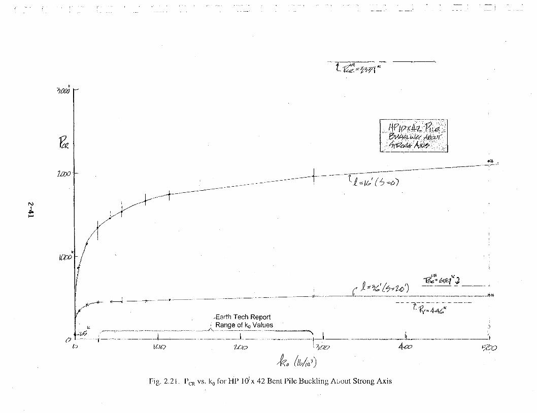
(J ·t~- i.-~··=·=~-===-=~---~--=~-=-=~~:o.__:_~-=~ .. =i=~~~-~=·-~~~~·-----~---:~=-:~=~--1-----·-·-·-·· .. ···------.. -·JL .. --~-----·--·------··--···--'i o tCJt7 Wo '. 7ioo 4-a:i 5(~tJ
*10 lth/,ri3)
Fig. 2.21. Pm vs. k0 for HP IO:x 42 Bent Pile Buckling A0out Strong Axis

N I ~ N>
tat?.
~ ·• .··'·
~ .··
I ./·· . -r
/Earth Tech Report / Range of k0 Values
r----·------·..A- -·-----[:; [) __ __,, _______ , ---·--------1--·--·----------1--l
IOC7 1.£JD ~o (lh./i11:1 ) ~.a
- -t-r:? - ~;;: - - - ----- ---t,r===956
--~---------------L ~? ?,
Fig. 2.22. P CR vs. ko for HP 12 x 53 Bent Pile Buckling About Strong Axis

N I
.;. w
Table 2.8. PcR vs. ko for HP 10 x 42 Pile Buckling in Transverse Direction or About Weak Axis
ko C=kob c114 (EI)tt4 4 a= ~C/ETw al kl (top pinned) kl (top fixed) P ca=(kl)ag2 Elw/l 2 {kL~)
(lb/in3) (lb/in2
) (per in.) l = 16' I= 36' l= 16' 1=36' l= 16' 1=36' l = 16' 1=36'
0 0 0 213.54 0 0 0 33* 33*
5 50 2.659 213.54 0.01245 2.39 5.38 2.52 3.52 3.30 5.19 478 211
15 150 3.500 213.54 0.01639 3.15 7.08 2.97 3.74 4.12 5.37 709 231
28.94 289 4.123 213.54 0.01931 3.71 8.34 3.15 3.82 4.65 5.45 858 239
43.4 434 4.564 213.54 0.02137 4.10 9.23 3.25 3.87 4.85 5.50 925 245
57.9 579 4.905 213.54 0.02297 4.41 9.92 3.32 3.92 4.97 5.53 969 249
86.8 868 5.428 213.54 0.02542 4.88 10.98 3.45 3.96 5.12 5.58 1036 254
115.7 1157 5.832 213.54 0.02731 5.24 11.80 3.50 4.00 5.17 5.62 1060 258
289.4 2894 7.335 213.54 0.03435 6.60 14.84 3.70 4.08 5.31 5.72 1145 268
578.8 5788 8.722 213.54 0.04084 7.84 17.64 3.80 4.16 5.40 5.78 1194 275
(EI)114 = (29,000,000 x 71.7)114 = 213.54
*Fork = 0 ~ 1 = 80 , p = 1.5rc2
Elw = 1.5 x rc2
x 29, 000 x 71.7 = 33 .4k 0
' cR 802xl22 6400x 144
p50%fixityeachend ~ 2rc2Elw = 2rc2 x29,000x 71.7=ll14k ~ p50%fixeachend = 2rc2 x29,000x 71.7 = 22 k
CR £2 1922 CR 4322 CJ
P =a A= 446k y y

Table 2.9. PCR vs. ko for HP 12 x 53 Pile Buckling in Transverse Direction or About Weak Axis
ko C=kob c114 (EI)114 al kl (ton ninned) kl (ton fixed ) P CR=(k~)2 aveElw/l 2 (kips)
a= ~C/E1w I= 16' 1=36' (lb/in3
) (lb/in2) I= 16' 1=36' I= 16' 1=36'
(per in.) I= 16' I =36'
0 0 0 246.35 0 0 0 59* 59*
5 60 2.783 246.35 0.01130 2.17 4.88 2.53 3.45 3.00 5.12 764 362
15 180 3.663 246.35 0.01487 2.86 6.42 2.87 3.67 3.90 5.31 1145 398
28.94 347 4.316 246.35 0.01752 3.36 7.57 3.07 3.76 4.37 5.42 1383 416
43.4 521 4.777 246.35 0.01939 3.72 8.38 3.17 3.84 4.64 5.46 1523 427
57.9 695 5.134 246.35 0.02084 4.00 9.00 3.24 3.87 4.80 5.50 1615 433
86.8 1042 5.682 246.35 0.02106 4.43 9.96 3.34 3.91 4.98 5.53 1729 440
115.7 1388 6.104 246.35 0.02478 4.76 10.70 3.40 3.94 5.15 5.56 1826 445
289.4 3473 7.677 246.35 0.03116 5.98 13.46 3.62 4.04 5.26 5.68 1970 466
578.8 6946 9.129 246.35 0.03706 7.12 16.01 3.74 4.12 5.37 5.75 2073 481
(El)114 = (29,000,000 x 127)114 = 246.35
*Fork = 0 ~ .e = 80 , P. = l.5n2Elw = 1.5n
2x29,000x127= 59 1<-
o . ' CR 8Q2 xl22 ~ X t44

{)
14
I:'i?r"' 11--4-& -- _y__ -·-- -- --- -·-·- --·
~~1:; 7;!,,,: {~.: 21/) ~---~+-_----·-··--··~·--=-~-~-------·--··-------:--···-·-Jf-------------
t 9
t;c/?;, f"ittt'l'"J" E:At'.J( /?.XIV
t~-iZ --.:: 2:U..> v.
Fig. 2.23. P CR vs. k0 for HP 10 x 42 Bent Pile Buckling About Weak Axis

i
\ I ''"' I • CS I \\ l~ I~
\I
-.l..
\
\
\
\-\ ~ \
2-46
I ~ I
I l~ I~
I l
0 ~

I ' i
' I I
I I
I ' I I
3. FAILURE MODES OF BRIDGE PILE BENTS DURING EXTREME SCOUR EVENTS
3.1 General
A typical bridge pile bent used by the ALDOT is shown in Fig. 3 .1. Possible failure modes
for such bents in a major flood/scour event are listed below and shown graphically in Fig. 3.2.
1. Buckling of Bent Piles in Longitudinal Direction (Pc?;Axis)
2. Buckling of Bent Piles in Transverse Direction (P~;Axis)
3. CrushingNielding of Piles
4.
5.
6.
Plunging Failure of Piles
Failure of Bent Cap
p M y MYX Local Yielding of Bent Piles (Duetocr2 =--±-x-±--)
A Ix ly
Bridge superstructure and bent cap maximum possible sidesway displacements vary from
, I bridge to bridge, and are different in the transverse and longitudinal directions. Limiting cases for
each of these two principle directions of interest are discussed in the ensuing sections.
It should be noted that all piles in the bent must fail in modes 1-4 above to have a
bent failure as each pile will get lean-on support from the adjacent piles if it reaches its failure load
first, i.e.,
Bent No~pes pPile pfailure = £,,,; failure (3.1)
1
Note further that the first two failure modes (piles buckling about their strong or weak axis) are
quite possible during a major scour event since the buckling capacities vary as the inverse of the
3-1

PRECAST CONCRETE CAP
DETAIL "B" r ~~~~~~~~~~~=a~~ ~1
Fig. 3.1. Typical AI.DOT Bridge Pile Bent
,t-,1
r'-<• I II
LONGITUDINAL DIRECTION
---- ---
I
I I
I
- - - - - -,- - - -LOCAL BENT
(1 BUCKLING ABOUT STRONG CAP FAILURE
\" AXIS iNGIT. DjECTION)
)! I cryxA=ry l'~ BUCKLING ABOUT WEAK AXIS fl~ (IN TRANSVERSE DIRECTION)
I' I
~ I~ ~'~
Vi ...... s:3 ~
I I : ii--;- ', SCOUR= s --L-------~-------------~~-------------~
LOCAL O'z = O'y _?7 I I
~ I
I
~ -t PILE PLUNGING FAILURE (Pp)
Fig. 3.2. Possible Failure Modes for Bridge Pile Bents
3-2

I !
square of the pile length above ground. This length will dramatically increase due to scour.
Crushing/yielding of the pile will not be possible since the scour event does not change Papplied or
I i
Py of the pile. Plunging of the pile due to inadequate soil support of the pile is possible but quite
I I
unlikely since all that is being lost during the scour event is the soil frictional resistance of the
soil scoured away. This should be a rather small percent of the pile resistance capacity. Failure
of the bent cap is unlikely due to the superstructure girders sitting directly above the piles. An
individual pile would need to plunge or buckle to significantly stress and possibly fail the bent
cap. Even in this case, the cap is unlikely to fail as will be shown in Section 3.6. Local yielding
of the HP piling near the new ground line (after the scour event) due
p + Mx y + MyX · · "bl H h 1 1 . . ldi tocrz =-------- stresses 1s qmte poss1 e. owever, sue oca pomt yie ng can A Ix ly
be tolerated and will not have serious consequences. Each of the failure modes above is
examined and discussed in greater detail in the ensuing sections.
3.2 Bent Pile Buck.ling in Longitudinal Direction
Maximum possible longitudinal displacements of bridge superstructures and bent caps
depends on the thermal expansion joint spacing included in the bridge superstructure. For
example, for the 272' long (made continuous for LL) span shown in Fig. 3.3, the 1 1/2" expansion
joint space between continuous spans appears to be quite realistic and good. If a 816' span bridge
is made up of three such continuous spans, as indicated in Fig. 3.4, then the first bent (see Fig.
3.4) will have the largest longitudinal movement or sidesway possible and will be 41/2" for the
bridge of Fig. 3.4.
3-3

For simple span bridges, the maximum possible longitudinal sidesway will also be the
first bent (see Fig. 3.5) and will be 1 Yl" for the seven span example bridge illustrated in Fig. 3.5.
Figure 3.6 makes use of an approximate equation to estimate the buckling load for
buckling in the longitudinal direction for three cases,
Case I - Sidesway
Case II - No Sidesway
Case ill - Limited Sidesway
Rshould be noted that the sidesway mode of buckling is possible during the construction of the
bridge before all spans are in place and connected to the abutments. Because of the sizeable
cons~ction loads, i.e., cranes, concrete trucks, etc. that may get on the partially constructed
bridge during this phase, the structural design of the pile bents for stability is probably controlled
------1J ( 1-1/2" EXP. JT.
8 SPANS @ 34' = 72' ~
t ··. 2S J .... k~A~E
CONTINUOUS FOR LL
~temp= a~TL
ASSUME BRIDGE IS MADE coN'tiNlJOUS FOR LL IN SUMMER WITH TEMP CONC. = 85°F
ASSUME IN WINTER AFTER A MAJOR FLOOD/SCOUR EVENT, THE TEMP DROPS TO 30°F
···~T = 55°F
= 6 X 10⁻⁶kllC/°F X 55°F X 272' X 12"
= 1.08' .. SAY 1.10" ( ••• 1-1/2" EXP. JT IS GOOD)
Fig. 3.3. Thermal Expansion/Contraction for 272' Span
3-4

I i
.1 I
; ;
' -· J
i.--------------816"---------------..i
1-1/2"1 272· = 8- 34· CONT. SPANS---it r272" = 8- 34" CONT. SPANS f----212· = 8- 34· CONT. SPANS r-1-1/2" EXP.
-~1-1/2"EXP.JT. 1..-i-1/2"EXP.JT. I JT.
·~·:·'·,·,··.•,:.,:.·.::.·.··.···· ·~····.·9: Q · 8 11 qir~., .. ___,___,...,.·,,· ':~.··· .. '.>·,· '·1) l l l l 1 p:x THIS lST BENT WILL HAVE LARGEST LONGITUDINAL MOVEMENT WHICH WILL BE,
NO. EXP. JTS. ~~AX = ;: 1i:XP .JT. CL. SPACE + CL. SPACE AT ONE ABUT.
FOR BRIDGE ABOVE,
2 ~MAX =
L L 1-1/2" + 1-1/2" = 4-1/2" 1
Fig. 3.4. Maximum Longitudinal Sidesway for 816' Continuous Span Bridge
SPAN=34"
AGAIN, THE lST BENT WILL ~ HAVE THE LARGEST LONGIT. MOVEMENT WHICH WILL BE,
!i~AX z (NO. SPACES -1) (CL SPACE BETWEEN SPANS)
FOR BRIDGE ABOVE,
ii MAX z (7 - 1) (l/4") = 1-l/2" L
Fig. 3.5. Maximum Longitudinal Sidesway for 238' Simple Span Bridge
3-5

APPROXIMATE EQ.
p _ N2n2EI CR - 4L2
WHERE N =NO. QUARTER WAVES INLENGTHL
p ' ' ' ' ' ,.,
' ' ' ' ... , ... / ' '
CASE I- SIDESWAY L /~N=l I I
FOR CASE I WE CAN GET LEAN-ON BRACING SUPPORT FROM THE CAP IF ALL PILES IN THE BENT ARE NOT AT PcR ALSO, WE CAN GET LEAN-ON SUPPORT FROM OTHER BENTS IF ALL BENTS IN THE BRIDGE ARE NOT LOADED TO pBENT
(1)2n2EI p CR ::::: ....;....;...
4-L-2 -
2.47EI
L2
CASE II - NO SIDESWAY
(3)2n2EI p CR ;::; -'--'---
4L 2
::::: 97t2EI
4L2
22.2EI -- L2
' ...
p
..
p
CR
FOR CASE II WE CAN NOT GET LEAN-ON SUPPORT FROM ADJACENT BENTS, BUT CAN GET LEAN-ON SUPPORT FROM ADJACENT PILES IN A BENT.
CASE III - LIMITED SIDESWAY
22.2EI PcRz --
,,~· :~
dL =LIMITED LONGIT. DISPL. = LIMITED SIDESWAY
NOTE FOR CASE II ABOVE ALSO APPLIES TO CASE III . L2
' IP i N:::; 3 . L \,
FACTOR OF 8-9 DIFFERENCE IN P CR FOR CASES II & III RELATIVE TO CASE I. USE LOWER VALUE OF 8.
LONGITUDINAL BUCKLING MODES:
CASE I
11 .... , ..... ~ ...... -~
I I I I I ... ,... .., ...
' ' ' ' ' ' ' ' ' '
. '
CASES II & III
Fig. 3.6. Longitudinal Buckling Loads and Modes for Case.s I, II, III.
3-6

'- . .:
by sidesway buckling in the longitudinal direction, i.e., Case I. However, after bridge
construction is completed, it can only undergo limited sidesway in the longitudinal direction, i.e.,
Case ill, and its longitudinal buckling capacity increases 8 fold as indicated in Fig. 3.6.
Because of limited sidesway possible in the longitudinal direction, existing bridge piles
and bents will have two values of Per for longitudinal buckling, i.e.,
n2EI Pero)= sidesway buckling at a load somewhat less than x
4.e2
Pc/2> = nonsidesway buckling after the occurrence of the limited sidesway of ~~ax
2n2Elx at a load of approximately £2
The nonsidesway buckling mode at Pc/2> will be required to actually fail the pile bent and bridge
at a load of approximately Pc?> z 8 Pero>. This sequence of events and failure loads are
summarized in Figs. 3.7 and 3.8 for a perfect pile/column and an imperfect pile/column
respectively. As indicated by these figures for reasonable imperfections, which are small,
p imperfect z p perfect er er (3.2)
and Per is independent of ~:;.'and
p - p (2) - 8 p flagpole pile/bent collapse of bent/bridge - er - er (3.3)
Alternatively, in terms of pile length for failure for a given P load,
V;"'""' = V = ~n2
EI, failure f 4p (3.4a)
L u.m,,, ..... .,, = I!" = ~ 2n2EI,
failure f p (3.4b)
3-7

........ ....... .......
' ' ' ' ' ' ' " \. \.
\ \
\ \
\ \
\ \
\ \ \ \ \ \ \ \ \
p
p(2) z 8P(l) z 8PFLAGPOLECOL. CR CR CR
p - p(2) COLLAPSE - CR
p
}rf8~
~ :: ,:'~ BUCKLED SHAPE/ '
FOR pC2) ~ ~ BUCKLED SHAPE CR •
L \ FOR Pg~ .. L1 (1)
L/2
\ \ \ \ \ \ \ \ I I I I
p(l) -+h--? ______ 8 __ <_2 --~-~0-~----CR
....._____._ ______ .....__ ____________ .,. L1 (1)
L/2 L1 = L1MAX
top long.
Fig. 3.7. P-L1 Curve for Perfect Bent Pile with Limited Sidesway Possible
3-8

........ ........
........
' I ,
I
,.-"
- !
' ' ' ' ' " " " '\ '\
\ \
\ \
\ \
\ \ \ \ \ \ \ \ \
p
\ \
p(2) ::::; gp0) ::::; gpFLAGPOLECOL CR qz CR
p - p(2) COLLAPSE - CR
p 1::.MAX ff long.
'; ,'
·-~ -: -~ BUCKLED SHAPE/'
FOR pg)__.; ~BUCKLED SHAPE
\ ~~l/2L \ \ \ I I I I I I I I
R L \ FOR p(l) \ CR " !::. (1)
L/2
P(l) 1
c~u2~---
~top
IL--~'--------'-----_.._ ~L/2 ~(l) ~ =~MAX
L/2 top long.
Fig. 3.8. P-!::. Curve for Imperfect Bent Pile with Limited Sidesway Possible
3-9

Therefore,
(3.5a)
or,
L;s = 2.828 L~ (3.5b)
Thus, for a pile bent modeled to buckle in a sides\\-'.ay mode as in Fig. 3.9a, or with limited
sidesway as in Fig. 3.9b, we would have,
r r , ... r·~ I I
........... 1 .... · I .
I . ' , . . Lo I Lo
Ls I . . CR . L LS
. . . CR
I S~R I
/ff/.? .r54 I I
/ff/.?
(a) (b)
SIDESWAY LIMITED SIDESWAY
Fig. 3.9. Bent Longitudinal Buckling Modeling
3-1 0

I ,_
and,
Or,
L~R = 2.828 L8cR = 2.828 (Lo + s~R)
= 2.828L0 + 2.828S~R
= L 0 +1.828L0 + 2.828S~R
S~ (see Fig 3.9b)
S~! = 1.828L0 + 2.828S~R
Thus, for a given Lo and P load, one can determineL8cR fromL' = ~n'EI, and then er 4P
S~! can then be calculated from
S~! = 1.828 Lo + 2.828 s~R
and the values for S~R and S~! can be compared.
(3.6)
(3.7)
(3.8)
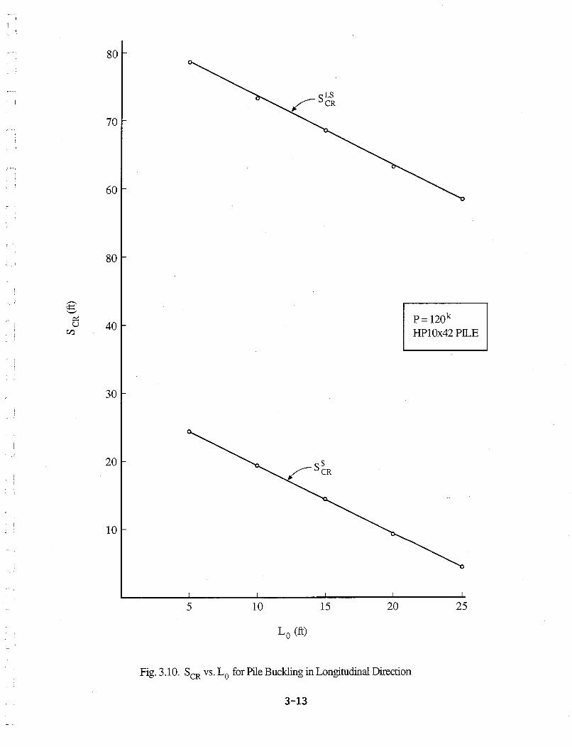
This was done for an HP10x42 pile under a 120k load and the results are shown in Fig.
3-11

3.10. Note in this figure that for a given pile under a given P-load, the critical scour value
decreases linearly with the initial length of the pile above ground, L0• Also, note the dramatic
increase in the critical scour value when the limited sidesway in the longitudinal direction is
considered.
Al . T s . . 1 . h th f . . ' s 1 n'EI, so smce LcR vanes mverse y wit e square root o P, i.e., Lc:R = , LcR and thus 4P
Ser is not real sensitive to the pile loading. This is illustrated for a HP10x42 pile with the cap
being 15' above the ground line in Fig. 3.11.
3.3 Bent Pile Buckling in Transverse Direction
Due to
• angle iron swaybracing
• batter piles on each end of the bent
• lateral support from continuous superstructure
as indicated in Fig. 3 .12, and if the bridge is continuous, or made continuous for live loads, due
to the lateral support provided to the pile bent at the top from the bridge superstructure, pile bents
of the type used by the ALDOT cannot sidesway in the transverse direction. Therefore, buckling
of the bent piles in the transverse direction (about pile's weak axis) will be a nonsidesway mode
with partial fixity at the top due to the bent cap (assume 50% fixity) and partial fixity at the
bottom due to the ground stiffness modulus (assume 50% fixity).
As explained in the previous section, after very limited sidesway in the longitudinal
direction, the top of a bent cap will be restrained from further longitudinal movement and the
piles will then act as pinned-ended columns at their top. This will render the pile as
3-12
80
70
60
80
40
30
20
10
1 I '
5 10 15 20
L 0 (ft)
Fig. 3.10. SCR vs. L0 for Pile Buckling in Longitudinal Direction
3-13
P= 120k HP10x42 PILE
25

,--... .;:::: '-'
C/l ~ .....:iU U'.l
~ C/lu U'.l
~
~ CIJ u
.....:i
120
100
80
60
40
20
L 0 = 15' HP10x42 PILE
o.__~~~__.~~~~ ........ ~~~~_._~~~~ ........ ~~~~ ...... 60 80 100 120 140 160
PILE LOAD (kips)
Fig. 3.11. L CR vs. SCR vs. P for Pile Buckling in Longitudinal Direction
3-14

approximately a fixed-pin ended column for buckling about its strong axis and will make
buckling of the pile about its weak axis the controlling mode of buckling failure. If one assumes
that the swaybracing does not buckle, then for the case of "H" = 25' (the largest value) and S =
20' (the largest probable value), as indicated in Fig. 3.12,
.emp = "E"or"G" +3.5'+S = ll.5 +3.5+ 20 = 29.25' 2 2
p~ = l.57t2Ely = l.57t
2(29,000)(71.l) = 250k
=~ 29.252 xl44
fassu:e50%
fixity at bottom
.eep =3.5'+S=3.5'+20=23.5'
p; = l.57t2Ely = l.57t2 (29,000)(71.7) =
387k
.e;P 23.52xl44
.eip = "E"or"G" +3.5'+S= Il.5 +3.5'+20'=26.4' 4 4
p = l.57t2(29,000)(71.7) = 307k
ip 26.42 xl44
3-15

DETAIL "B" SCALD J/4" = l'-0"
,, TWO STORY BENT SWAYBRACING TABLES
"H" "E" "A" "B" "C" WT. LBS.
20'-o" 6'-6·" 25'-6" 25'-6" 27'-3" 1205
21'-o" 7'-6" 25'-6" 25'-6" 27'-7" 1209
22'-o" 8'-6"" 25'-6" 25'-6" 28'-0" 1216
23'-0" 9'-6" 25'-6" 25'-6" 28'-5" 1223
24'-0" 10'-6'.' 25'-6" 25'-6" 28'-11" 1230 I 25'-0" 11'-6" 25'-6" 25'-6" 29'-5" 1238 I Largest-;
"H" Value BATTEN llflGHT TO BE ADDED TO ABOlif TABLES. 10-BA TTENS R[Q'D, 5/16" X 7 1/2" X l'-6 1/4"@ 12.1,f EACH.
~ NOTE: llfLWN0 So: / DETAIL "E' NOTE: WEIGHT Gfll[N IS TOTAL FOR TWO PIECES OF EACH
LENGTH OF SWA '/BRACING SHOWN IN BOTH TABLES. SINGLE STORY BENT SWAYBRACING TABLES
"H" "G" "D" WT. LBS.
13'-0" 7'-5" 25'-8"
14'-'0" 8'-5" 26'-1"
15'-0" 9'-5" 26'-7"
16'-0" 10'-5" 27'-1"
17'-;-0" 11'-5" 27'-7"
18'-o" 12'-5" 28'-1"
19'-0" 13'-5" 28'-8"
SCALE: J/4" = l'-0" 0 WHERE Pll[ BENT IS LOCATED IN
WATER, ENCASEMENT SHALL EXTEND J'-0" MIN. ABOW:: NORMAL WATER LINE AS DETERMINED BY ENGINEER.
HP 12 x SJ
* WHERE "H" IS LESS THAN IJ FEET. EXTEND THE ENCASEMENT TO THE BOTTOM OF THE CAP AND OMIT SWA YBRACING.
GROUND LINE OR ~. MUD LINE
11:::111:::111:::111:::1 :::111:::111:::111:::111
1::::1 "' ~ 111: 2l ~"'~
"'~<:::> ~~kl~ ~ ~~~ ~ ~g~ _1,(..j~~
'-4--+--+--'~ ""
SUBSTITUTED FOR ,f2 BARS.) _J L! l I IZ'...;.E:,
t'-5" souARE PILE ENCASEMENT.J L@2'-o" i MAY BE USED IN LIEU OF 24" i 1
ROUND ENCASEMENTS. PAY -- :n OUANTITIES BASED ON ROUND lL.J ENCASEMENTS. __
Fig. 3.12. Bent Transverse Buckling
3-16
PILE ENCASEMENT DETAILS
SCALE: 1/2" = /'-o·
395
401
409
417
425
432
441 I
Due to "lean-on" bracing provided by adjacent piles,
P~t = 1:Pg~es = 250k + 2(307) + 2(387) = 1638k
Note, however, that the swaybracing members are relatively small angle iron and whereas they
should prevent swaying of the bent, they will probably buckle themself rather than prevent
buckling of the individual piling (see right end pile in Fig. 3.12). Therefore, it will be assumed
that the swaybracing and batter piles will prevent transverse sidesway buckling of the bents, but
that the bent piling will buckle in the transverse direction from the bent cap (assume 50% fixity)
to the new ground lin~ after scour (assume 50% fixity) at a load per pile of,
(3.9)
where
f = "H' (on pile bent standards)+ S =height from new ground level to top of bent cap.
And, due to "lean-on" bracing from adjacent piles,
pbent = 1:Ppiles CR CR
(3.10)
Using Eqn. (3.9) yields the elastic values of PcR shown in Table 3.1 for f values from 15'-40' for
HP 10 x 42 HP and 12 x 53 piles. These elastic failure loads are presented graphically in the
form of PcR vs. f curves in Fig. 3.13a. As indicated in Chapter 2, for PcR > Pyl2, inelastic
buckling loads should be used as shown in Fig. 3.13b.
3--1/'

Table 3.1. Elastic PCR vs. f for HP 10x42 and HP 12x53 Piles*
f (ft) P~iIOx42 (kips)
15 1267
20 713
25 456
30 317
35 233
40 178
*PcR Based on Buckling in Transverse Direction as given by Eqn. (3.9).
p~Ox 42 = 12.4 X 36 = 446K
P~2xSJ = 15.5 X 36 = 558
3-18
P~:12xs3 (kips)
2244
1263
808
561
413 ...
316

! '
' i I
~ I I I
2oook I \ \ Pf vs. t CURVE FOR PILE \ \ YIELDING OR BUCKLING \ ABOUT ITS WEAK AXIS \ \ \ \
1500k \ \ \ \ \ \
0 " ,.-., \ C/l
\ 0.. ;g \ \
<:.) \ \
.2 \ \ :I§
1oook \ \
Q.. \ \ \ \ \ \
\ \ \ '><
\ \.
'ci,._ " "' "' p 12x53 - 55gk " " " " y -
"' 5ook p 10x42 _ 446k " y - "
15 20 25 30 35 40
e (ft)
Fig. 3.13a. ElasticTransverse/WeakAxis Buckling of a Single Bent Pile for a Given Length ( t) Above Ground Line After Scour
3-19

600
500
400
,---. en 0..
:.g 300 .._,
i:i::: u 0...
w I
N 200 0
100-
0 0 5
A36STEEL e = "H" + S
J35.74' 10 15 20 25 30 35 40
e (ft)
Fig. 3. l 3b. Transverse/Weak Axis Buckling of a Single Bent Pile for a Given Length ( t) Above Ground Line After Scour
l42.54; 45 50

,, I I I
The assumption of 50% fixity at the pile top, i.e., at the bent cap, seems quite
reasonable since the piles are typically embedded 1 ft. into the cap as indicated in Fig.
3.15 or connected by weldment to anchor plates in the cap as indicated in Fig. 3.16.
It appears that bridge pile bents are sometimes used without x-bracing but with
pile encasement extending from 3 feet below ground line to the underside of the cap.
However, because of the light steel spiral employed in the encasement, and the vibratory
nature of bridge and bent loads due to truck traffic, the pile concrete encasement could be
lost with time (though ALDOT engineers report no such losses). Thus, let us examine
the case of a bent without x-bracing and without pile encasement, but with batter piles at
each end of the bent to see if the batter piles will provide sufficient lateral bracing to
prevent sidesway buckling in the lateral or transverse direction. To simplify the analysis,
we will work with the simplified bent model shown in Fig. 3.14.
Fig. 3.14. Simplified Bent Model
3-21
h Sine

3'-0"
/'- 6 .• /'-6"
'I
'
!'-0"
2'-0"
1'-c:>'' / '- o'' i-----i----------~---· S~CTION D;.D
c .... p R..
II 11 1' ,1 I
11
p
11 I ,1 p I I I
11-I II I 11 I
I :1 I
NOR 1'1\ ..... L 'NA•!."' OR.. GRo ui'oolc l1t-.1E.
Fig. 3.15. Pile Connections/Embedment to Bent Cap
3-22
HoaPs 11-"f
6''

' ' ' I
2'-3"
~ 5/B" x 6" STUDS I~
.. '1'~
L (8) A-Ill BARS
BATTER OUTSIDE PILING I 1/2" PER FOOT
5'-9"
/ \ ~' .........__ LJ8, . l ! ii 1 I • I • 2·! ! 1'-IJ"j, ! I 2· J 11ti I 1'-1 I J 1/2
i 1._,.. · 1 I t-a· I
AL TERNA TE ANCHOR SYSTEM SC4l,[.• ,. = 1·-0·
'\_B-86 BARS & PLATES
HP 12 x 53
5'-9"
7'-9" LEVEL
r-- S'fMM. ABOUT C.L. ' 5'-9"
ELEVATION - INTERMEDIATE BENT SCALE: 1/2· = 7'-o·
SEE DETAIL ·x·
HPl2 x 53
72'-0" TAPER CROWN 3/16'.
CROWN TEMPLATE
WRAP EDGE OF fMBEOED P WITH 1/8" THICK X 3/4" WIDE COMPRESSIVE MATERIAL. (TYP.)
fMBfOfO f2
DETAIL ";('
STffL PLACEMENT DETAIL SCAL[· 1 • = 7'-0"
/4 BARS -
l'-9"
I l/2"fJ PIN
/ '-6' LAP BARS
CAP SECTION SCALE: 7" = l'-0"
_ _.6_"_,__£_. I
B-86 BARS & ANCHOR PLATES SCAL[· I 1/2" = /'-0"
Fig. 3 .16. Pile Connections by Anchor Plates to Bent Cap
3-23

For this simplified model,
tan a= 1·5
=0.125 12
a= 7.125°
:. e = 90°-a = 82.875°
Cos 8= F/2
FP
F = F/2 P Cos 8
F h ---x--i5 = FPLP = 2Cos e Sine= Fh
p APEP APEP 2APEPCos 8Sin e
i5 Cos 8 =i
~
~ = 5P = Fh . Cos 8 2APEPCos2 8 Sin 8
F = 2APEPCos 28 Sin 8 ~
. h
kequlv
Therefore for a HP 10 x 42 bent,
k _ 2x12.4in2 x 29,000 ksi x Cos2 82.815 x Sin 82.895 = 10,980k Equiv - h h
For a HP 12 x 53 bent (A = 15.5 in2),
k - 13,725k Equiv - h
Thus, kEquiv for various values of h are as shown in Table 3.2 and in Fig.3.17.
3-24

Table 3.2 Bent kEa for 15' s h s 40'
h k 10x42 EQ
k 12x53 EQ
15' (180") 61.0 k/in 76.3 k/in
20' (240") 45.8 57.2
25' (300") 36.6 45.8
30' (360") 30.5 38.1
35' (420") 26.1 32.7
40' (480") 22.9 28.6
In general, columns bracing requirements are
• Stiffness - to hold the braced point in place
• Strength - Brace force and strength are directly related to the initial
out-of-straightness and load eccentricities.
For an ideal column pinned at its base the ideal bracing requirements would be
as indicated in Fig. 3.18.
Thus,
k Pe ideal =h
For the simplified bent model shown in Fig. 3.14,
pPile kpile __ e_
ideal - h
LPpile 5ppile kbent __ e ___ e_
ideal- h - h
Values of ke!~1 are given in Table 3.3 for steel HP 10 x 42 and HP 12 x 53 for the
simplified bent in Fig. 3.14. These values of ke!~1 are also shown plotted on Fig.
3.17 for convenience in comparing the k-values.
3-25

'2 ~
:il ~
...:..:::
0
~ > s g
...:..:::
80
70
60
50
40
30
20
10
k 10x42 ideal
12x53 kEQUIV
oi-.~~~~"--~~~~.i.-~~~~..i.-~~~~..i.-~~~~...i..-~~
30 40 35 15 20 25
h (ft)
Fig. 3.17. kEQ vs h for Simplified Bent Model for HP 10 x 12andHP12 x 53 Piles
3-26

ip
BRACE PROPERTIES
f3 (k/ft) Stiffness
Fbr (k) Strength
n:2 EI Per = -- Per= ? L'
L
\ \ I 1 I I I I I
I -+F
tp
f3Li.L > PL!. no sidesway
f3Li. L < P Li. sidesway
f3L = Per
IDEAL BRACE STIFFNESS
f3; Ideal Brace Stiffness J.
I f3; = P.1 Li
I I
I Per= n:'E 1 /L'
K= 1.0
Figure 3.18. Ideal Brace Stiffness (Yura)
3-27

Table 3.3. Simplified Bent kideai vs t Values
p = n2Ely kbent _ 5Pe
ideal - ,f, t e ,e,2
p10x42 e
p12x53 e k 10x42 k 12x53
15' (180") 633K 1122K 17.6 k/in 31.2 k/in 20' (200") 356 631 7.42 13.1 25' (300") 228 404 3.80 6.73 30' (360") 158 280 2.19 3.89 35' (420") 116 206 1.38 2.45 40' (480") 89 158k 0.93 1.65
For columns/piles with a fixed base requires a top brace with a stiffness of five
times that of the ideal brace stiffness shown in Fig. 3.18 to achieve 95% of the
fully braced PcR (3). This condition is shown in Fig. 3.19.
The K = 0. 7 condition shown in Fig. 3.19 is approximately the condition of
ALDOTs bents in the transverse direction if they are presented from sideswaying.
Thus, for these bents,
kpile :::::: 5Pe ideal ,f,
no piles kbent - L 5Pe
ideal - ,f,
For a 5 pile bent, the k:~1 values given in Table 3.3 should be multiplied by 5 to
determine the k~:~~ for the actual pile end conditions. This would be true if Ptailure
= PcR = elastic buckling load. However, for the smaller length bent columns/piles
(where kideal is fairly large), the pile failure mode will be one of inelastic buckling
at loads well below the elastic buckling loads. In this case,
kbent ,.,, ideal -
no piles L 5PcR
,f,
3-28

BRACED CANTILEVER
No sidesway - K = 0.7 2r-~~~...:.....~_:..;.......;:.:.:..._~~~
1 2 3 4 5
t Brace Design p LIP e
EFFECT OF BASE CONDITION
6
"'· , K--'. K•0.7 t Pe 1 / -------------~--------~-=-!~~------- I h /1r r 1
1 2 3 4 5 6
t Full Bracing fl L/P e
Figure 3.19. Brace Stiffness Required for Fixed Base Condition
3-29

Elastic and inelastic buckling loads were determined from Fig. 3.20 and k~:~1
used these values to determine k~:~1 for a 5-pile bent. These are shown in Table
3.4. A plot of these kidea1 values are shown superimposed on the approximate
kequivalent vs h (or t) curves developed earlier in Fig. 3.2 1. Note that this plot
indicates that the batter piles should provide sufficient lateral support to develop
the nonsidesway capacity of the pile bent, i.e., keq of batter piles > k~:~1 •
However, fort or h values below 20 feet, the approximate kEa and the k~:~1
values are quite close and the bents should be x-braced in addition to having the
batter piles. Lateral load F vs Ii curves with and without vertical bent cap
loadings should be developed for a pile bent without x-bracing via linear and
nonlinear stiffness analysis to verify the kequivalent values shown in Fig. 3.2 1.
Table 3.4. Elastic and Inelastic Buckling Loads and k~:~~ Values for 5-Pile Bents of HP 10 x 42 and HP 12 x 53 Piles
p ~ n2Etly no piles
kbent L 5 per* e .f.2 ideal=
.e.
t (or h) p10 x 42 CR
p12 x 53 CR HP 10 x42 HP 12 x 53
15' (180") 366K 487K 50.8 k/in 67.6 k/in 20' (240") 305 433 3t8 45.1 25' (300") 228 366 . 19.0 30.5 30' (360") 158 280 11.0 19.4 35' (420") 116 206 6.90 12.3 40' (480") 89 158 4.64 8.23
* Values shown are for a 5-pile bent.
3-30

w I w .....
600
p ~x53 = 55gk .--=---::::::::.:::--------------------
500
400
300 l/2p12x53 _ 279k
y -
1/2 p ~lx42 = 223k
200
100
HP12x53
HP10x42
o.__~~~-'-~~~ ........ ~~~ ........ ~~~ ......... ~~~__...._~~~.._~~~ ........ ~~~ ........ ~ 0 5 10 15 20 25 30 35 40
e (ft)
Fig. 3.20. Elastic and Inelastic Values of Pe for HP 10 x 42 and HP 12 x 53 Piles

,.-... c::
~ ~ C<l ~ a)
cc ~ ~
0
~ @' ~
80
70
60
50
40
30
20
10
\ \
\
\ \ \ \
\ \ \
\
\
\
\ \ ~
\ \
\ \
\
\ \
"Q(
\ \
\ \
\ \
\ \
\ \
\
\ \o
\
' \ ~
\
'
\ \
'
\ \
' ' '° '- k 12x53 BENT '--f ideal
' ' ' ' k10x42sV, ideal ',
""' 'o... .......
........ .......
....... ........ ...._ -~ --
........ ........ ...._ -0
---~ oL.-~~~~..._~~~~..1..--~~~~...1.-~~~~-'-~~~~..J....~~
30 40 35 15 20 25
tor h (ft)
Fig. 3.21. Approximate Values ofkEQ and kideal for 5-Pile Bents of HP 10 x 12andHP12 x 53 Piles
3-32

I '
i
3.4 Crushing or Yielding of Piles
As indicated in Section 3.1, crushing or yielding of the bent piles is really not a viable
I j
failure mode. An extreme scour event does not change P max applied or PY and hence a bent that will
not fail in this mode before scolir, will not fail in this mode after scour.
3.5 Plunging Failure of Piles/Bent
All static pile formulas estimate pile capacity by the following basic equation:
(3.11)
where Pu = ultimate pile capacity
P1 =load carried in point bearing
Pr = load carried by friction along perimeter of pile
Differences in Eqn. (3.11) lie in the methods used to evaluate the friction and point-
bearing portions of the equation. Appendix D shows results from an earlier study (2) on pile
capacity predictions by a static formula vs. P failure for some Alabama pile load test data.
Plunging of the bent piles due to inadequate pile tip bearing and side frictional forces
during an extreme scour event is possible, but not very likely. Assuming the scour is local
around the piles and not over the entire river bed adjacent to the bent, then the soil confining
pressures at greater depths will remain about the same. Thus, the loss of soil support during the
scour event will be the frictional resistance provided by the soil over the top 15 feet or so of the
embedded pile (over the depth of the soil scoured away). Normally the top 15 feet of soil is soft
or loose and does not provide a high percentage of the pile frictional resistance. Losing this soil
resistance via scour of the soil would reduce the factor of safety of the pile/bent below the design
3-33

value, but should still provide a F .S. > 1.0. As indicated in Appendix D, a reasonable and probable
upper-bound estimate for Pr in the top layer( s) that will be scoured away would be,
Thus, for an S = 15',
Or, each pile in the bent would lose 22.5k of its support capacity during a 15 foot scour event. This
should not result in a pile/bent plunging failure.
An alternative approach in estimating the percent of pile capacity loss during a major scour
event is given below. Recall that
If the pile tip is founded in good soil, we should be able to assume for a steel H-pile (see Table D.1
in Appendix D),
pt z 0.10 p capacity
pf z 0.90 p capacity
At a particular bridge site, assume that S = 15', and the soil at the pile tip is good such that
Prz 0.90Pcapacity
pt z 0.10 p capacity
For this case, for piles of different original embedment length below ground, f, bg, estimates of
reductions in Pr and P capacity would be as shown in Table 3.5 (see Fig. 3.22 for parameter definitions).
As can be seen in Table 3.5, an f, bg ~ 2.5 S would probably be sufficient to not have a
pile plunging failure (would retain 64% of original pile capacity). However, to be a bit more
conservative, we will say that an f, bg ~ 3 S will be sufficient to prevent a pile plunging failure
(would retain 70% of original pile capacity). It should be noted that for steel H-piles with their 3-34

ip
"H" = L 0
BENT CAP
STEEL HP PILE
FIRM SOIL STRATUM (AT PILE TIP)
Fig. 3.22. Minimum Pile-Soil Setting Conditions Needed to Prevent a Pile Plunging Failure
3-35

tips in a good cohesive soil, Pt is considerably larger than the 10% of Pcapacity used in the case
above. This is also true of prestressed concrete piles with their tips in either cohesionless or
cohesive soils. For these cases, the loss of Pcapacity due to scour will be smaller than for the case
described above, and thus a pile plunging failure should not occur in a scour event in these cases
for an Qbg as low as 2.0 S. Again, to be a bit more conservative, we will say that an Qbg ~ 2.5 S
will be sufficient to prevent a pile plunging failure in these cases ..
Table 3.5. Estimated Pile Capacity Loss/Retained After Extreme Scour Event
.e bg s (ft) (ft)
f. bg (ft)
70 15 55
60 15 45
50 15 35
45<3l 15 30
40 15 25
37.5(4) 15 22.5
30 15 15
(I)% Loss of Pr= S/ f bg x 100 <2l % Loss of Pcapacity = 0.90 x % Loss of Pr <3l f bg corresponding to f bg = 3.0 S
<4l f bg corresponding to f bg = 2.5 S
Pr. p capacity= pf+ pt % % Loss<0 Retained % Loss<2l % Retained
21.5 78.5 19.4 80.6
25 75 22.5 77.5
30 70 27.0 73.0
33.3 66.7 30.0 70.0
37.5 62.5 33.8 66.2
40 60 36.0 64.0
50 50 45.0 55.0
3-36

In summary, for a given pile/bent, if the pile tip is embedded in a firm soil with good
bearing capacity, and if the length of the pile below the original ground line is greater than 3.0
times the maximum scour, S to occur at the site, then the piles and bent should continue to have a
F.S. > 1.0 against a pile plunging failure. Or, if the tip is founded in a good cohesive soil or the
pile is a prestressed concrete pile then the pile should not plunge if Qbg;;::. 2.5 S. These minimum
conditions are graphically illustrated in Fig. 3.22. If neither of the above conditions is met at the
site, then a closer examination should be made concerning a possible pile plunging failure
3.6 Failure of Bent Cap
Failure of the pile bent cap is unlikely as indicated earlier due to the superstructure
girders sitting directly above the piles. Significant relative vertical displacement between piles
could cause failure of the cap in cases where the cap is lightly reinforced (as some are). Let us
examine the forces set up in the cap in the event of a pile plunging or buckling failure.
From an examination of numerous pile bent standards, many pile cap geometries and pile
spacings appear to be as shown in Fig. 3.23. For the pile cap indicated in this figure, for the pile
to plunge or buckle, the P 10ad would have to exceed 137.8k + Pplunging or Pbuckling of the pile as can be
seen from FBD(a) in Fig. 3.23. The Pioact will never be this large and the failure indicated in Fig.
3.23 will not occur.
Lightly reinforced bent cap such as the one shown in Fig. 3.24 are very susceptible to cap
flexural failures as indicated. They provide very little reserve strength for resisting an applied
P 10ad if the pile capacity Ppile is exceeded as indicated in Fig. 3.24. However, even in this case,
due to transverse continuity of the bridge superstructure, there would be a redistribution of loads
across the width of the bridge (and bent cap) if at a given pile location, P 1oad > Ppiie·
3-37

7'
Vend
7' (PILE SPACING)
PILE CAP FOR SINGLE PILE PLUNGING OR BUCKLING
. ·I~ 1~~:~~~~;2CINGJ u 2 1/2" 4 - #9 s 2
- (A8 = 4 x .994 = 3.98in )
t- .8 .. 5fc' = 2.55ksi 2.60" = a+G-
ax 24,_."._,.x~2.5,~5~= 159k ) Mu
Mu ( 1 _·:· · .:. t J Mu a= 2
·60
" 0---.3.98 X 40 = 159k
68.9 : .. 68.9k
FBD (a)
CHECK SHEAR CAPACITY
Vu = <PVc + <J>Vs _1-, Anfyd
= <j>(2Yfc bwd)+ <j>(-. -, ,.-. ) ·. ' ' .... s ·' = 0.85(2"13000 x 24 x 19.5)
Vend
2Vend
Mu= 159k (19.5" - 1.30")
= 241 1k
2Mu 2x241 1k = 68.9k =
7' 7
= 137.8k
•'•IF PLOAD ~ 137.8k + PcR- PILE (BUCKLINGOR PLUNGING)
THE PILE CAP WILL FAIL AS INDICATED ABOVE
0 85( 2 x 0.20 x 40 x 19.5) + . 12
= 43.56k + 22.lOk
k vu= 65.7 • CLOSE ENOUGH SHEAR CAPACITY TO DEVELOP FULL END Mu' S OF THE CAP.
Fig. 3.23. Examination of Pile Cap Flexural Failure for Case of Well Reinforced Cap.
3-38

I I
r r11 ··"::·.· .. ·. \J· ..
M Ve u
7' 7' (PILE SPACING)
PILE CAP ,r
<D .•. :, :· '". : . . Mu
FBD (a)
ax 2.55 x 36" = 35.2
a= 0.384"
24"
Mu= 159k (19.5" - 1.30")
= 73211k = 61 lk
Vend = 2x61 1k
7' 7
2V end = 34.8k
.·.IF PLOAD ~ 34.8k + PCR-PILE (BUCKLING
CHECK SHEAR CAPACITY
Vu= <!>Ye+ <!>Vs
OR PLUNGING) THE PILE CAP WILL TRY TO FAIL AS INDICATED ABOVE. HOWEVER IF THIS CONDITION IS EVER REACHED, THERE WILL BE A REDISTRIBUTION OF LOAD ACROSS THE WIDTH OF THE BRIDGE (AND BENT CAP}.
_1- A0 fyd = cj>(2V'fc' bwd) + cj>(-S-)
= 0.85(2~3000 x 30 x 21)
+ 0.85( 2 x 0.20 x 40 x 21 ) 12
= 58.7k + 23.8k
= 82.5k + CAP HAS SUFFICIENT SHEAR CAPACITY TO DEVELOP FULL ENDMu'S.
Fig. 3.24. Examination of Pile Cap Flexural Failure for Case of Lightly Reinforced Cap.
3-39
24"

3. 7 Local Yielding of Pile Due to Combined Normal Stresses
As indicated earlier, local yielding of the bent piles near the new ground line after an
P My M x extreme scour event due to - - ± __ x - ± __ Y - stresses is quite possible.
A Ix IY
Strong axis bending stresses at the ground line caused by longitudinal truck braking
forces when coupled with axial pile stresses and nominal bending about the pile weak-axis can
easily reach the pile yield stress. However, such high local stresses can be tolerated and will not
lead to collapse of the bridge bent. In the worse-case scenario, they could lead to plastic hinges
forming at the base of the pile bents which would continue to function in a stable and effective
manner as indicated in Fig. 3.25. However, due to the large flexibility of the pile bents in the
longitudinal direction because of their relatively small Ix value and their long length above
ground (""H" + S), most of a truck's longitudinal braking force will be transmitted horizontally
along the superstructure into the abutment.
The large longitudinal flexibility (and small stiffness) of a typical pile bent is indicated in
Fig. 3.25. Note also in Fig. 3.25 that for I-girder line ofloading, a truck braking force, F8 , of
4.8k would result in a plastic hinge developing at the groundline for a 30" high HP 10 x 42 pile
bent. Actual truck braking forces are larger than this and hence, most of a truck braking force
will have to be transmitted longitudinally to an abutment.
3-40

I i
I i
'·1
L
k11 =
HP10x42~
' ' '.,. .. ' ' ' ' ' ' '
7 .• .•
L=20' ,25' ,30'
L = "H" + S
L'.1TOP = f11 =
r TRUCK BRAKING FORCE
-- -- --
PLASTIC HINGE (WORST CASE SENERIO)
.~HP10x42 FOR L= 20' • f11 = Fkx203xl 728
= 0.75711/k .. k11 = l.32k/ll
1
F11
L=30'
FOR L= 25'
FOR L= 30'
3x29,000x210
f 11 = 1.4811 /k k11 = 0.676k/1l
fu = 2.56ll/k ku = 0.39lk/ll
NOTE THE LARGE FLEXIBILITIES (f11) AND SMALL STIFFNESS (k11 ) VALUES FOR THE BENT.
FB x 30' =Mp= 1451k
FB = 4.8k _. NOTE, THIS WOULD RESULT IN L'.1ToP =
~
.·.MOST OF TRUCK BRAKING FORCE WILL HAVE TO BE TRANSMITTED TO AN ABUTMENT.
= 12.26"-
Mp= Ciy X Zx
36x48.3 =---12
= 1451k
Fig. 3.25. Worst-Case Scenario for Plie Bending Stresses and Large Longitudinal Bent Flexibilities.
3-41
' ' .1
i I I i
4. PILE/BENT TRIAL ANALYSES AND PARAMETER SENSITIVITIES USING FB-PIER
4.1 General
PB-Pier is a graphical user interface computer program operating in a windows
environment for the analysis of pile group foundations. The program was developed by the
University of Florida for the Florida Department of Transportation and Federal Highway
Administration. There are eight general types of pile foundation problems that the user may
model with PB-Pier. They are:
1) pile and cap only
2) general bridge piers
3) high mast lighting and signs
4) retaining walls on top of pile groups
5) sound walls
6) equivalent stiffness of pile group analysis
7) pile bents
8) column analysis
These eight problem types or categories are illustrated graphically in Fig. 4.1. Each of the eight
categories starts the user with an initial default data structure and limits the screens that the user
subsequently modifies or asks the user if they wish to change problem type
Early in the investigation, we secured the computer program PB-Pier and began
modelling and analyzing the example problems in the Users Guide and Manual to learn how to
use the program and its capabilities. Later, we performed parameter sensitivity analyses using
4-1

Soil Layer 1
Soil Layer I
Soil Layer I
(a) Single Pile/shaft (b) Group of Piles/Shafts with Cap
1. Piles and Cap Only
+-Pile Group
3. High Mast Lighting and Signs
5. Sound Walls
36'
I iln 'l n ci / /
JO JO lcip ldp
/ 30 kip
Wind Load
-
30'
- - h,,,~-+
RecsaSand. y,• 119p~f +•JS 4S'
I
'r. PILE BENTS
Pier
Pile Cap
Piles or · Shaft•
.2. General Bridge Piers
Soil Layer I
Soi1Layer2 :~
Soil La.ycr3 \
~ (a) Soil nod Q:intHeyer Wall (b) FB-PJer Ide::iliz:::ation
4. Retaining Walls On Top Of Deep Foundations
... ""]
eese Sand =I 19 lb/ft'
R y
<I> =35'
~ 1 J -
-
I
80 ft
·-- "7 -
6. Equivalent Pile Group Stiffness
I 20ft
l
20~ ( .i. ~120Dkip-in
'f
Colucnn: 30" Square
~::.P~~::i!Vrad)
Lo"" 200 kips conccatrated 1200 kip-in moliwlt
23, COLUMN ANALYSIS
Fig. 4.1. Eight Problem Types That Can Be Modeled with FB-Pier
4-2

i the program to gain a better understanding of the behavior of pile bents and their sensitivities to I '
various system parameters. These analyses and their results are presented in the following
sections.
4.2 Develop P-Ll Curves for a Pile Bent in Longitudinal Direction for Various Levels of Scour
For this problem, rather than work with the complete bent, one pile in the bent was
analyzed by itself as indicated in Fig. 4.2. As indicated in the figure, an HP 10 x 42 pile was
,..., used with an initial length above ground of L = 20 ft. The top of the pile/bent cap was assumed
to be pinned as indicated in Fig. 4.2 and the P load was assumed to be applied with an
eccentricity of 3 in. as indicated. The load eccentricity was used because it was though to be
realistic and also so that the pile would be a beam-column and thus have a beam-column P-Ll
curve. As P was incrementally increased from zero to failure (where FB-Pier would not
converge) the pile lateral deflection atL/2 was monitored and later plotted. As the amount of
scour was increased in increments of 5 ft. to a maximum value of 20 ft. (i.e., S = 0, 5, 10, 15, 20),
,., L was always taken as the length of pile above ground. Soil and other parameter values used in
the FB-Pier modeling are shown in Table 4.1. The resulting P-Ll t 12 curves generated in these
analyses are shown in Fig. 4.3.
4-3

MAX SCOUR~
ORIGINAL GROUND LINE
s =5'
- - - s = 10'
- - - s = 15'
LEVEL .J __ --- S=20'
'"(' I
='''-='''= ~ HP10x42 PILE
l
Fig. 4.2. Single Pile Analyzed to Determine P-L1u2 Curve in Longitudinal Direction
4-4

i I
Table 4.1. Soil and Other Parameter Values Used in PB-Pier Modeling of Problems Shown in Figs. 4.2 and 4.4.
Pile: HP 10 x 42
Pile length: 80 ft. Initial pile length above ground: 20 ft. Sand (Reese):
Tip:
Unit weight = 120 pcf Internal friction angle = 35 Subgrade modulus = 150 lb./in."3 Poisson's ratio= 0.3 Shear modulus = 3.5 ksi Vertical failure shear= 1152 psf Torsional shear stress= 1152 psf
Shear modulus = 3.5 ksi Poisson's ratio = 0.35 Axial bearing failure = 640 kips
Scour depth (ft.):
0, 5, 10, 15, 20
4-5

250
200
~
ti) c. 150 ·-~ .._. "C
.p. ca I 0 O'I
..J 100 ' ' . ----------------------------:--------------------------------+--------------- ---------------.---- --··-----··· . .
50
0 0 0.5 1 1.5 2 2.5 3
buVl' Deflection {in)
Fig. 4.3. P-d1.12 Curves in Longitudinal Direction for Single HP 10 x 42 Pile in Fig. 4.2.

I ',
I
' i I ,
4.3 Develop P-A Curves for a Pile Bent in Transverse Direction for Various Levels of Scour
The same pile bent and setting as analyzed for the longitudinal P-A,12 curves in the
previous section is investigated here to develop transverse P-Atop curves. However, because of
the batter of the end piles, the whole bent must be modeled and analyzed to obtain the curves.
Hence, the pile bent modeled and analyzed to determine the P-Atop curves for scour values of 0,
5', 10', 15', and 20' is as shown in Fig. 4.4. In the analyses, the 1 k horizontal force at the bent cap
was held constant and the Pioads were incrementally increased until PB-Pier would not converge
(this was viewed as the failure load). Note in this case, the piles were bending about their weak
axis (Y-Y axis). Soil and other parameter values used in the PB-Pier modeling were the same as
those used in the previous analyses and are given in Table 4.1. The resulting P-Atop curves
generated in the analyses are shown in Fig. 4.5.
4.4 Effect of Pile Batter on Bent P-Atop Curves in Transverse Direction
To determine the sensitivity of pile bent P-Atop curves in the transverse direction, the pile
bent of the previous section (see Fig. 4.4) was re-analyzed using PB-Pier, for end pile batters of 1
in 12 or 0.083, 11/2 in 12 or 0.125, and 2 in 12 or 0.167. The same soil setting and conditions as
identified in Table 4.1 were used in the analyses, and the results are shown in Figs. 4.6-4.8. To
make the results more friendly to assessing the effects of end pile batter, the data is re-plotted in
Figs. 4.9 - 4.13 to show the curves for all three batters on the same plot for each scour level.
4.5 Effect of Soil Subgrade Modulus on Single Bent Pile P-A Curve in Longitudinal Direction
To gain an understanding of the sensitivity of a bent pile P-A,12 curve and Pfailure
prediction to the supporting soil subgrade modulus, a single pile was analyzed using PB-Pier and
4-7

3'
2'0 fc' = 4000 psi
BENT CAP
8'(TYP.) lL 1·
I
TRANSVERSE DIRECTION
4 t .. p p p
ORIGINAL GROUND / ,,.._BENDING ABOUT iWEAKAXIS LINE
=i""""'~;:;c;_..;>-n-;;;i::_---i-+---+-+---i.-1---..:::I:;...l....+-~;;:,":::~ c - rv I I I I I I I I • 1 '-' - v
I I I I I I I I I I I I 1
---~,--------LL---~~----i~------~i----S=5' I I I I I I I I \
I I I I I I I I I .
- - - '-1- - - - - - - - _ 1_ I_ - - - - 1 _1 _ - - - l - - - - - - - \- L - - - s = 1 O' I I I I I I I I I
I I I I I I I .I I
- - !... .j.. - - - - - - - - _I_ I_ - - - _I _1 _ - - - 1 - - - - - - - ._, ..::.1 - - ..:. s = '15' I I I I I I I I I
I I I I I I I I I
- _! ..J - - - - - - - - - -1-
1'- - - - -
1-
1- - - - ..! - ~ - - - - - - ..l 2 '- - s - 20' .
11 I I I I I I\ I I -,, II II II MAX II
I / I I I I I I I I ~ ..L.J... ..L.J... J_...J... SCOUR ..0-
60'
'T'f .,.--r .,.--r yr LEVEL .........,.-' I I I I I I I I I
- _lll __ llL - r HP!Ox42 -
·y
Fig. 4.4. Pile Bent Analyzed to Determine P-~top Curve in Transverse Direction
4-8

250
200
..-. U) a. 150 ·-~ ._
"C (tJ
~ 0 I ...I c.o
100
50 - -- --- - - - - - - - - - - -, - - - - - -- - - - - - - - - - - - - - -- - - - ~ - - - - - - - - - - - - - - - -- - - -- - ·~ - - --
0
0 0.5 1 1.5 2 2.5 3 3.5
.6~- Deflection (in} Fig. 4.5. P-dtop Curves in Transverse Direction for HP 10 x 42 Pile Bent in Fig. 4.4

250
200
-tn 150 c. ·-Jill: -"CS cu
~ 0 I ..J ..... 100
0
50
0
'
' ' ' ------------------- -----1----------- ------ -- ---- -r---- ---------------------1- ---- ---------- -----------r-------------------------1-- -- ---- ---------- --- -----i ·------------------- -----
i i i __ ,,,,,,,, .. ,-·----·~·-···--··---··----·-"'"·---··--t·--···---·-····-·----··r·"'"X : ~,,.. .. ¥<"T : : : l ,,,,.P,.._.,P" : l : :
: ...... ~#........ : : : : ... --- --- -- --- ---r--/--;-~~----l--------------------:-_:::r:::.::::::.:::.:::;:;;_o;T_" _____ ,,~·-··"""'f"'·"~::c:c:::'.:::·;:·;:::r:::='; ______________ -- -
: t : .... ············ : : : __.._. : / : ..... ··· .... : _..-1---··--_..--·-·r )f .. ··················j········ .. :~:·· i -----·--- ! i
---- --/1 /'"<-------!~ -- ___ _.______ --:------- ---i--¥' ... / ' ' .
I VI/ . ! ! ! ~t. .;::~. : : l : i ,•I I I I I --------- _____ ; ______ /J. ..... 1-...... -----------l-------------------·-----J __________________________ . _________________________ J __________________________ [____ ~- s-Sft f .:·:I : : : : --rw-- -; l : : : : : ' .• ' l~- ' . ' . I ,:::::: Jl : ~ : ! 1 .' r: I I I I
-+-S=20 --s=15ft .... ,,,,, .... s= 1 Oft
~s=Oft i f : : : : i
1---~l .:/ i i l i l
0 0.5 1 1.5 ") e..
Deflection {in) 2.5 3
Fig. 4.6. P-~top Curves in Transverse Direction for Pile Bent in Fig. 4.4 for Batter= 0.083
3.5

.i::a I ...... ......
..-..
"' a. ·-~ .._. "C ca 0
...J
250
200
150
100
50
0 0
----------------------r----------------------,---------------------- --------------1 I
I I _________________________________________ )
_._ S=O --i- S=5ft -lr- S=1 Oft
S=15ft -+-- S=20ft
I I
----------------~
----------------,
______ L ________________ _ _ _____________________ J _____________________ _
I
0.5 Defleci\on (in) 1.5 2
Fig. 4.7. P-~10P Curves in Transverse Direction for Pile Bent in Fig. 4.4 for Batter= 0.125

250
200
--s=O .-..
150 "' c. ·-~ -+- S=5ft
----------------4-------------
~ S=10ft .._. "C ca --*- S=15ft
.j:lo 0 100 I ..J ..... N
I -------~-----------------------
\ -e- S=20ft
50 I
- -----------!-----------------------,-----------------------~-----------------------
0 0 0.5 Deflection (in) 1.5 2
Fig. 4.8. P-d10P Curves in Transverse Direction for Pile Bent in Fig. 4.4 for Batter = 0.167

250
200
.-.. "' 150 c. ·-~ .._.. "'C ca
.i:io 0
I _. 100
...... w
50
0
0
I I
------------~-----------------------~-----------------------
' I I I I I I I I
-----------~-----------------------~------ ~ Batter=0.083 ----------_._ Batter=0.125
, -- Batter=0.167 -------------~----------------------->-------~---------------------
0.5 1 Deflection {in)
1.5
Fig. 4.9. P-d10
P Curves in Transverse Direction for Pile Bent in Fig. 4.4 for All Batters for S = 0.
2

250
200
..-.. 150 "' D. ·-~ ..._.. "C m
~ 0 100 I -' I-' ~
50
0
0
- - - - - - - - - - T - - - - - - - - - - - - - r - - - - - - - - - - - - -1- - - - - - - - - - - - - -, - - - - - - - - - - - - -
I I I I 4( I
----1-------------T-------------r-------------1--------------,-------------I I I I I I I I
-1- - - - - - - - - - - - - I - - - - - - - - - - - - - T - - - - ------,-------------I I
---~-------------1-------------T----I
0.5 1 1.5
-t- B~atter=0.125
-..-- B~atter=0.167
2 2.5
Deflection (in)
_____ , ____________ _ I
3 3.5
Fig. 4.10. P-Ll10P Curves in Transverse Direction for Pile Bent in Fig. 4.4 for All Batters for S = 5 ft.

180
160
140
120 ..-.
"' a. 100 ·-~ .._.. "C
80 cu ~ 0 I ..J .....
CJ"1
60
40
20
0 0
I
I I I I I I I
--~------------- --------------------------,-------------,-------------' I
I I I
I I I
- - - - - - - - - - _I_ - - - - - - - - - - - - J - - - - - - - - - - - - - L - - - - - - - - - - - - -I I I I
_ - - __ - - - - - L - - - - _ - - _ - - __ -1- _ - - - - - - _ - - __ --1 _____________ L ____________ _
I I I I I I
I I
. I - - - - - - ; - - - - - - - - - - - - - I- - - - - - - - - - - - - -1- - - - - - - - - - - - - ; - - - - - - - - - - - - - t- - - - - - - - - - - - - -
I I I I
----------,-------------r------------1 ___.___ Batter=0.083
Batter=0.125 I I I -------------,-------------,------------'
---*- Batter=0.167 - - - - - -:- -- --- - --- --- ~ - - - - - - - - - - - - - ~ -- - - - - - - - - - --i.----------~,---------~--1- - - -- - - - - - -
I I I I I
I I I I I
--~-------------J-------------L-------------1-------------J-------------L-------------I I I I I l r r 1 1 I I I
0.5 1 1.5 2 2.5 3 3.5 Deflection (in)
Fig. 4.11. P-d10P Curves in Transverse Direction for Pile Bent in Fig. 4.4 for All Batters for S = I 0 ft.

160
140
120
...-.. 100 "' a. ·-~ .._. 80 "C ca
.;:.. 0 I ..J 60 ..... °'
40
20
0 0
I ---------------L ______________ J ______________ _ I
------~--------------~---------------
I I I I I I ---------------r--------------,---------------1 I I I I
I I I ---~---------------L---------------L ______________ J ______________ _
I I I
---------1---------------1----- -- Batter=0.083 1 I
Batter=0.125 I
I I -----------,---------------1-----__._ Batter=0.167
---------------~---------------~---------------!---------------~---------------' I I I I I I I I I
0.5 1 1.5 Deflection (in)
2 2.5
Fig. 4.12. P-~top Curves in Transverse Direction for Pile Bent iin Fig. 4.4 for All Batters for S = 15 ft.
3

140
120
100
80
60
40
20
0
0
- - - _I_ -I
0.5
___________ 1 _____________ L ____________ J ____________ _
I I I I I
---~------------~-------------~-------------
' I I I
I I I
I I I -------------r------------~-------------1-------------
' I
- - - - - - - - - - - - -1 - Batter=0.083 , __._ Batter=0.125
I I -------1-------------T-------------1 I__...._ Batter=0.167
I I
I I _____________ L ____________ J _____________ i ____________ _
I I I
1 1.5 2 2.5 3 3.5
Deflection (in)
Fig. 4.13. P-~top Curves in Transverse Direction for Pile Bent in Fig. 4.4 for all Batters for S = 20 ft.

a broad range ofko (lb./in.3) values. The single pile setting/conditions are as shown in Fig. 4.14
and Table 4.2. Again, an eccentricity of loading of 4" was used to produce an applied end
moment at the pile top of 4" x P so as to produce a P-aU2 curve as qualitatively indicated in Fig.
4.14. Soil and other parameter values used in the FB-Pier modeling are given in Table 4.2. The
resulting P-at,2 curves generated in these analyses are shown in Fig. 4.15 for a HP 10 x 42 pile
and in Fig. 4.16 for a HP 12 x 53 pile. Note in Figs. 4.15 and 4.16 that the PCR value fork= 0
had to be determined analytically or using the FB-Pier column analysis category as indicated in
Fig. 4.17. Also note in Figs. 4.15 and 4.16 that the "failure" loads (program would not continue)
implied by FB-Pier for the other k values (the largest P-load for each k value) was the load to
cause first yielding of most highly stressed fiber in the pile rather than the load where the pile
becomes unstable. To get the stability limit or buckling load for each k value, we should increase
the pile yield stress to a large value and rerun the analyses. Also note in Figs. 4.15 and 4.16 that
the subgrade modulus has a small effect on the P-a curve but almost no effect on the failure load
(as determined by FB-Pier). Analytical analyses also indicate that the soil subgrade modulus has
little effect on a pile's buckling load.
4.6 Effect of Soil Internal Friction Angle on Single Bent Pile P-a Curve in Longitudinal Direction
The same pile conditions as indicated in Fig. 4.14 and Table 4.2 were used to assess the
effects of the soil internal friction angle, <I>, on the P-a curve and predicted failure load. For this
case, however, the soil subgrade modulus was held constant at a value ofk = 85.05 lb./in3 and <I>
was varied from
cl> = 20°' 25°' 30°' 35°' 40°
4-18

I I
-L= 16'
L=72'
Lg= 56'
t LONGITUDINAL DIRECTION
'e=4
" .. APPLY p AT 4" Pcrv--' p ECENTRICITY p
TO GET P-~ CURVE AND PcR AS SHOWN
HP{10x42} 12x53
.:!Ji< Il '*° - SCOUR = 0 " " " '• " " " " " " '•
0
" " llLsoILk = T:Y 1, •1 ....
5.0 lb/in 3
15.0 28.94 43.4 57.87 86.81 115.7 289.4 578.8
:· :: •! •• .. .. ., .. .. .. .. .. .... 1· :;
=ill" "Ill= -k=bxk
k10x42 = 1 O" x k
k12x42 = lO" X k
~L/2
Fig. 4.14. Single Pile Analyzed to Determine Sensitivity of P-~L;2 Curve and PcR to Soil Modulus, k
4-19

Table 4.2. Soil and Other Parameter Values Used in FB-Pier Modeling of Problem Shown in Fig. 5.14
Pile: HP 10 x 42, HP 12 x 53
Length: 72 ft., with 16 ft. above the mudline
Sand (O'Neill):
Tip:
Unit weight = 110 pcf Internal friction angle = 35° Poisson's Ratio= 0.3 Shear modulus = 1.5 ksi Vertical failure shear = 600 psf Torsional shear stress = 600 psf
Shear modulus = 3.5 ksi Poisson's Ratio = 0.35 Axial bearing failure = 640 kips
Subgrade modulus: Ranging from 5.0 to 578.8 (lb./in.3)
5.0, 15.0, 28.94, 43.4, 57.87, 86.81, 115.7, 289.4, 578.8

. I I I
240~~~~~.,-~~~~-,.-~~~~--,-~~~~-,-~~~~---.,~~~~~,-~~~---i
-e- k=28.94 --+- k=43.4. --"*- k=57.87 -e- k=86.81
Note - Local yielding is probably occurring before pile becomes unstable
200 ~ k=115.7 -v- k=289.4
160
Ci) a. :i2 -120 i:::l Ctl _g
80
40
0
-8-- k=5 ---*-- k=15 ~ k=578.8
0.1 0.2
Oy= 36 ksi e=4" S=O L=72'
0.3 0.4 0.5 0.6 Displacement (in) (~Ci in Longitudinal Direction)
Fig. 4.15. P-frr:,2 in Longitudinal Direction for HP 10 x 42 Pile in Fig. 4.14 for a Range of k Values.
4-21
0.7

250
200
100
50
0
-e- k=28.94 --'*- k=43.4 ~ k=57.87 -B- k=86.81 -4-- k=115.7 ~ k=289.4 -A- k=5 ---*--- k=15 - k=578.8
0.1 0.2 0.3 0.4
Displacement (in) ( .6.L/2
in Longitudinal Direction)
Oy= 36.ksi e=4" S=O L=72'
0.5
Fig. 4.16. P-dtn in Longitudinal Direction for HP 12 x 53 Pile in Fig. 4:14 for a Range of k Values.
4-22
0.6

I I
120
100
Ci) 80 0.. g
"O Ctl 0
....J 60
0
7t2X 29,000 X 393 = p = lSOk
722 X 144 e
-e- HP12x53 --*- HP10x42
7t2
x 29,000 x 210_p =80k ---722X144 e .>1<--------1
, " ~?
No Surrounding IJ4f& Soil l , k = o i L::'7z. Pin=Pin Column k
2 4 6 8 10 12 14 Displacement (in) ( .6.Lii in Longitudinal Direction)
Fig. 4.17. Column Analysis Results for L = 72 ft. Using PB-Pier
4-23

Also, only the HP 12 x 53 pile was analyzed. The results of this sensitivity analysis using
PB-Pier are shown in Fig. 4.18. Note in that figure that the internal friction angle, <I>, has no
significant influence on the P-Li curve or the failure load.
4. 7 Effect of Clay Soil Su Value on Single Bent Pile P-A Curve in Longitudinal Direction
The same pile conditions as indicated in Fig. 4.14 and Table 4.2 were used to assess the
effects of clay soil Su values on the P-Li curve and predicted failure load. However, for this case
the soil subgrade modulus was held constant and Su was varied from
Su = 250 psf, 500 psf, 1000 psf (for HP 10 x 42 pile)
Su= 250 psf, 500 psf, 1000 psf, 1500 psf (for HP 12 x 53 pile)
The PB-Pier P-Li results are shown in Fig. 4.19 for the HP 10 x 42 pile and in Fig. 4.20 for the
HP 12 x 53 pile. Note in these figures that the clay Su value had a dampened effect on the P-Li
curve (deflections reduced by a factor of about 0.57 for an Su increase by a factor of 6.0) and no
significant influence on the failure load. Again, it appears that PB-Pier is detecting a local
yielding of the pile as the failure load rather than an instability.
4.8 Comparison of FB-Pier and Granholm Eq Results of Pile Buckling for Various ~Soils
The pile conditions used in Chapter 2 to determine the buckling loads using
Granholm's Eqns. were also modeled and analyzed using PB-Pier. In these analyses, a large
value of oY was used (oy = 360 ksi) so that PB-Pier would continue to increment.the load and
iterate to get the buckling load, and a large value of pile tip axial bearing load was used to
assure a non-plunging failure of the piles. The pile conditions and soil k0 values used along
with the other parameter values used in the PB-Pier analysis are shown in Fig. 4.21 and
4-24

I ! I
I i
,, '
-e- phi=20 l
--+- phi=25 --*- phi=30 -8- phi=35
250 ~ phi=40
-C/l Q. ~
200
:; 150 ell 0 ~
100
50
0 0.05 0.1 0.15 0.2 Dispalcement (in)
' k = 85.05 lb/in3
0.25 0.3 0.35
Fig. 4.18. P-At12 in Longitudinal Direction for HP 12 x 53 Pile in Fig. 4.14 in Sandy Soil for a Range of <P Values
4-25
0.4

200
160
-(/)
c.. :2 -120 "O ctl
.3
80
40
0
--e- Su=250psf ~ Su=500psf --*- Su=1 OOOpsf
0.1 0.2 0.3 0.4 0.5 0.6 Displacement (in)
Fig. 4.19. P-~,12 in Longitudinal Direction for HP 10 x 42 Pile in Fig. 4.14 in Clay Soil for a Range of Su Values
4-26
0.7

I I
-e- Su=250psf --+- Su=500psf -*- Su=1 OOOpsf
250 -e- Su=1500psf
200
en 0..
:;;;: -150 "O ctl
.3
100
50
0 0.1 0.2 0.3 Displacement (in)
0.4 0.5
Fig. 4.20. P-~-r12 in Longitudinal Direction for HP 12 x 53 Pile in Fig. 4.14 in Clay Soil for a Range of Su Values
4-27
0.6

INITIAL GROUND LINE
~LONGITUDINAL DIRECTION
'p
r HP10x42
to= 16'
s =20'
~ ~ ~¥-:. .. ·····~·~r··· .... :T"" •• 11 11 11 II 11 II 11 II
~ 11 II 11 II 11 II 11 II
11 11 1• .. _ ...
{pile= 80'
SOILko =
( 0 "'\
5.0 15.0 28.94 43.4 57.9 86.8 115.7 289.4 578.8
lb/in 3
Fig. 4.21. Pile Conditions for Comparison of FB-Pier and Granholm's Equations Results
4-28

I !
Table 4.3. In the FB-Pier analysis, only buckling of a single HP 10 x 42 pile about its strong
axis was considered.
Results of the FB-Pier analyses are shown in Fig. 4.22 for S = 0 and in Fig. 4.23 for S =
20'. Both of these figures indicate a great insensitivity of the P-A curve and the
failure/buckling load to the soil subgrade modulus, k. This same behavior was evident in the
analytical analysis conducted in Chapter 2. Plots showing P cR vs. I<a as determined by
Granholm Eqn. and by FB-Pier for both S = 0 and S = 20' are presented in Fig. 4.24 for
convenience in comparing the two analysis results. Note in this figure that the results for both
analyses for S = 20' are in good agreement. However, for S = O' the Granholm Eqn. gave much
larger failure loads. This is probably due to Granholm Eqn. assuming elastic behavior of the
pile and not including geometric nonlinear effects.
4-29

Table 4.3. Soil and Other Parameter Values in PB-Pier Modeling of Problem Shown in Fig. 4.21.
Pile: HP 10 x 42, S = 0 and 20 ft., eccentricity = 0.4 in,, yielding stress = 360 ksi
Length: 80 ft., with 16 ft. above the mudline
Sand (O'Neill):
Unit Weight= 110 pcf Internal friction angle = 20 Poisson's Ratio= 0.3 Shear Modulus = 1.5 ksi Vertical Failure Shear = 5000 p&f Torsional Shear Stress = 5000 psf
Tip:
Shear Modulus = 3.5 ksi Poisson's Ratio = 0.35 Axial bearing failure = 1000 kips
Subgrade Modulus: Ranging from 5 to 578.8 (lb./in.3)
5, 15, 28.94, 43.4, 57.87, 86.81, 115.7, 289.4, 578.8
4-30

1000
800
600
400
200
0
HP1 Ox42, S=O
-e- k=5 --+- k=15 - k=28.94 --*-- k=43.4 -B- k=57.9 ~ k=86.8 -v- k=115.7 -A- k=289.4 -*-- k=578.8
Oy = 360 ksi e = 0.40" L=80' Q= 16' S=O
0.5 1.5 2 Displacement (in) ( t.Wi in Longitudinal Direction)
Fig. 4.22. P-d,12 in Longitudinal Direction for Pile in Fig. 4.21 and Table 4.3 for a Range of k Values and S = 0.
4-31
2.5

400
350
300
Ci: 250 g "'O C'il
.3 200
150
100
50
0
HP1 Ox42, 8=20ft
-e- k=5 -+- k=15 - k=28.94 ~ k=43.4 -e- k=57.9 -+- k=86.8 -'V- k=115.7 -A- k=289.4 __._. k=578.8
O'y = 360 ksi e =0.40" L=80' ~= 16' S=20
0.5 1 1.5 2 2.5 3 3.5 Displacement (in) ( ilc-
2 in Longitudinal Direction)
Fig. 4.23. P-At12 in Longitudinal Direction for Pile in Fig. 4.21 and Table 4.3 for a Range of k Values and. S = 20 ft
4-'-32
4

I I
i I
'
I I I
I I
2000
.".
~ 1500 '~ 11 g ,_ (..)
0...
1000
HP1 Ox42, Per vs Ko
-e- S=O, FBPier
--+-- S=20ft, FBPier
- S=O, from paper ->+- S=20ft, from paper
FB-Pier (S = 0)
-7<---¥--···
Granholm Eqn. (S = 20') -_______ ____,.<--- ~ --···----- .. -·•··· .. -·-··-·---.... -"
100 200 300
KO (lb/in3)
FB Pier (S = 20')
400 500
Fig. 4.24. Comparison of FB-Pier and Granholm Eqn. P cR vs. k0 Results for Single HP 10 x 42 Pile Buckling About Its Strong Axis.
4-33
600

5. BRIDGE PILE/BENT MAXIMUM VERTICAL LOADS
5.1 General
Most of the bridge superstructure and pile bents of interest in this investigation were
designed for H20 or HS20 truck and lane loads. These standard AASHTO loadings are shown in
Figs. 5.1 and 5.2. In placing truck and lane loads in traffic lanes, the AASHTO design truck and
lane loadings are meant to cover a 10-ft. width. These loads are then placed in 12 ft. traffic lanes
spaced across the bridge from curb-to-curb. If the curb-to-curb width is between 20 ft. and 24 ft.,
two design lanes are used, each of which is half the curb-to-curb distance. The number and
spacing of design traffic lanes is based on the layout which creates the maximum stress. Table
5.1 shows the number of design lanes based on a bridge's curb-to-curb width. Most of the
bridges of interest in this study appear to have widths in the range of 24-40 ft., and thus would
have 2 to 3 design traffic lanes of load applied to them.
Table 5.1. Design Traffic Lanes (8)
Curb-to-Curb Width No. of Lanes
20 to 30 ft. 2
30 to 42 ft. 3
42 to 54 ft. 4
54 to 66 ft. 5
66 to 78 ft. 6
78 to 90 ft. 7
90 to 102 ft. 8
102 to 114 ft. 9
114 to 126 ft. 10
5-1

H20·44 8,000 LB H15·44 6,000 LB
32,000 LB 24,000 LB
HS20·44 8,000 LB HS15·44 6,000 LB
32,000 LB 24,000 LB
32,000 LB 24,000 LB
;;::• 14'-0" .:;;: :;;:• 4 14'-0' •• 4 ;;:: v ~·;;:: N ~ Ni I ~ ~
·01 10 O• I 0 10
--IJIT][]-----------ioAwl-----· -----[]J][I----~---------------~-' I I I • I I I I I I
I I "/ I I
--1 o.1wi-----------lo.4wl-----· -----~----~---------------~-, I I I / I
W =TOTAL WEIGHT OF TRUCK AND LOAD
10'-0" CLEARANCE AND
LOAD LANE WIDTH
2·-0·-l 14 5'-0" .1 ~ 2'-0"
Standard H Trucks
W = COMBINED WEIGHT ON THE FIRST TWO AXLES, WHICH IS THE SAME AS FOR THE CORRESPONDING H TRUCK. .............
V =VARIABLE SPACING ";~4 F)"Tb 30 FT INCLUSIVE. SPACING TO BE USED IS TH1,'WAICH PRODUCES MAXIMUM STRESSES.
-U1H,,,fi1? 10'-0' CLEARANCE AND
LOAD LANE WIDTH
2·-0"-l 14 5·-o· ./ l-2·-o·
Standard HS Trucks
Fig. 5.1. AASHTO Standard H & HS Design Trucks.
1120-44 LOADING HS20-44 LOADING
H15-44 LOADING HS15-44 LOADING
Fig. 5.2. AASHTO Hand HS Lane Loading
5-2

I ,
I I
5.2 Pile/Bent Dead Load
Procedure for estimating the dead load (DL) force acting on top of a bent pile and on the
bent are shown below. These procedures are then applied to the typical ALDOT deck-girder
superstructure shown in Fig. 5.3. Two procedures are shown,
Method I - for cases where estimated superstructure quantities are readily available on an
ALDOT Standard.
Method II - for cases where estimated quantities are not readily available.
For Method II, a girder-line approach is taken to first determine the DL acting on a bent pile.
Method I:
Superstructure weight per span = W ssT
WssT =Concrete quantity x 27 ft. 3/yd.3 x 0.145k/ft.3 +Rebar Wt.+ No. girders x L x wgir
Bent Cap Weight = W cap
Wcap = bcap x dcap x girder spacing x No. girders x 0.150k/ft.3
For the S-4034P superstructure standard in Fig. 5.3, the estimated DLs would be as
follows.
WssT = 37.6 yd.3 x 27 ft. 3/yd.3 x 0.145k/ft.3 + 12.6k + 6 x 34 x 0.287kl'
= 147.2k + 12.6k + 58.5k =218.3k
wcap = 2' x 3' x 7' x 6 x 0.150k/ft.3 = 37.8k
FD\ENT = 256.1 k
FDLPILE = 256.1/6 = 42.7k/pile
Method II:
Superstructure DL per pile is,
Deck: 7'/12 x Girder Spac. x L x 0.150k/ft.3
5-3

BEGIN OR END BRIDGE (BACK <?:·ABUT. SKW,L.)
SR.JT.ARMOR fl (SEE STD. OWG.
NO.Nol)~
I
FJ 70"F
TYPICAL END SPAN TYPICAL INTERIOR SPAN NOTE: SEE POU~ING SCHEDUl.E FOR LOCATION OF -- SPLICES FOR BARS TYPE D AND BARS TYPE£.
SCALE '1/4"= l'O"
11; SPAN 12 SPAN 112 SPAN I SPAN 1(2 SPAN I I/? SPAN l
fr---------/' 3<'o' o•'.o"
3/4~ OPEN JT. JN BARRIER RAIL ~! W.L. •• Jr
£i~~=9;jJ~ij ABUT. INT. BENT INT. BENT . INT. BENT @
-- --- ELEVATION OPEN JOINT
BARS s/5 ® 1010.C.
I .. i £-WcoNi~; {)RIP SE.AD •
J• i __,,_., i
Sff STD. DWG. NO l-131 FOR DETAILS OF BARRIER RAIL
~ GOR.
NO SC.ALE
If. SYMN.
SECTION A-A SCALE= 112-"" r·o'
Fig. 5.3. A Typical ALDOT Deck-Girder Superstructure
SECTION 8-8 SCALE~l/2~,,.,.f"-0"'
SCALE : _ l/4".::.1:..0"
* PREMOi..DED BITUMINOUS FILLER UNDER WESWALL BE7WCE.N ELASTOMER/a PADS SHALL BE ~ 7HICJ< SY THE WWTH OF THE WESWALL AND SHAH EXTEND OUT TC O/JT Of OUTSIDE GIRDERS. f/Lt.£R MAY BE cur IN PlECES TO EXT ENO sETWE£N STEPS ON CAf.S. FILLER SHALL 8£ fJTT£D AROUND DOWELS. THE PIP£ SLEEVES ov:R THE DOWELS SHALL REST ON TOP OF THE FILLER.
&~D~fo.Jg~~ ~g~~~ 1jLATE
BARS A •s (TOP) BARS C {BTMJ
NOT£: END VIEW OF WEBWALL Al -- INTERIOR SPAN @ O.~EN JOINT
SAME AS SECTION 8-B,E.XCEP r BARRIER RAIL TAPEA4
44."'it (/.S. Dl/\~.824, X 1~t LG. PIPE SLEEVE PL/'.::ED OVER DOWELS WITH TOP PLVGGEO (TO BE PAID FOR AS 11UlS. SiRVCTVRAL STEEL")
2 .. 3/4"0 X f~9~ PLAIN DOWELS~ /!.!°CJ.C. (7/,2" EACH SIDE OF ( GIRDER)(OMIT OUTSIDE DOWEL ON £.XTERIOR GDRSJ
(EMBED 12")--'--'------'-~
FE.Cl, .. 1:11. STATIC Plll¢Al. -l:T TOTAL CllV, HO. PROJ. HO, Y£.U: NO, SHCCf'9
SECTION E-E SCALE :.3/4~1~0"
ESTIMATED QUANTITIES END SPAN ! INT. SPMI i /Ni. :iF-AN ,•1/0P!N JT. .j UNIT ! 1r£M
36.4 I 37.6 !
~.5 12,605 I . SID I IJ I
37.5 I CU YOS. [ BRIDGE CONCRETE SUPEP.SrRUC7'URE 111950 I LBS.
500 f LBS.
I LLQPE, I 3~/0~,
I STEEL REINFORCEMENT
I STRUCTURAL STEEL
NOT,"• GIRDERS SHAL.L BE AAS.H.T.Q TYPE I -.., PRETENSIONEO ·PRESTr!ESSED CONCJ?.ETE
GIRDERS. SEE SHUT 2 OF 2 roR DETAll.S.
SECTION C- C cONsr. .ir. ..---.----,,..-,,,,----.----sc--......"""s""'3'""~-~-''~"",--o-FALABAMA
:~ HIGHWAY OEPARTMENT
•• STANDARD •,e •• 34' PRESTRESSED CONC. BEAM SPANS WITH POURED-IN-PLACE SLAB MADE CONTINUOUS FOR LIVE LOAD 40' ROADWAY. WITH BARRfER RAIL
· HS~0'-44 LOADf./llG O' SKEW STANOAB.O o~··~~
S-4034.>P - . iiDFSJGNE.O:.STDS.P5C-40248R cf P5c-li&IE)(it) ~~'""-'~,,,;;~S,~l;!....-...j SWET~ ~·~.:;,·,~~i
,;.,i, ... .., ..... ;;;;.; ..... -. ....... ~~<~Qr.,.~F.~~~;~~.i.~~-~ .. ~ .... iiiii!.~~0------;;j,, .. .-...,;""'··~~~:~~~~"~~~~0~

I I :
, I
!
r I
Bent Diaph: 11 '/12 x Girder Depth x Girder Spac. x 0.150k/ft.3
Barrier Rails: 2 x wbr x IJNo. piles per bent
Girder: W girder X L
Bent Cap: 3' x 2' x girder spac. x 0.150kl'
Therefore, for the S-4034 P standard,
Deck: 7'/12 x 7' x 34' x 0.150 = Bent Diaph: 11/12 x 2.33' x 7' x 0.150 = 2.24k
Barrier Rails: (2 x 0.390 x 34')/6 = 4.42
Girder: 0.287kl1 x 34 = Bent Cap: 3' x 2' x 7' x 0.150kl1 = 6.3k
43.5k/pile
FOL _ Bent- 43.5 x 6 = 261k
5.3 Maximum Pile/Bent Truck and Lane Load
A girder-line approach is taken to estimate the maximum vehicular IL (plus impact) on a
bent pile, and the approach is illustrated with its application to the superstructure shown in Fig.
5.3. A somewhat similar approach is taken to obtain the maximum vertical load on the pile bent.
pLLpilemax for Fig. 5.3 is as follows: 7' 1· ~r r <L 64psf
,:·=·=·=·=·=·=·=·=·=·=·=·=·r 1·,.·:' :··\L_ : z I DECK
GIRDER
20 6 20 6 pLL =16k +- X 16k +- X 4k +- X 4k +- X 16k +0.064 X 7' X 34'
pile max 34 34 34 34
= 16k +9.41+0.71+2.35+2.82+15.23=46.52k
pLIL = 46.52 X 1.3 = 60.5k p1emax L
, l.F. 5-5

pu.bentmax for Fig. 5.3 is determined using 3 design lane loads and 2 design truck lanes of
loading as indicated below.
3-64psf DESIGN LANE LOADS
REVERSE LOADS GOING IN OTHER DIRECTION, I.E., DOUBLE TRUCKLOAD ON BENT TO ACCOUNT FOR OTHER LANE.
10' 10' 10'
[\1~·~ r1!] SUPERSTRUCTURE
SECTIONS
[ 20 6 20 6 J P~~tmax = 32k +- X 32k +- X 8k +- X 8k +- X 32k 2+[0.064X10' X 34']3 34 34 34 34
= [32+18.82+1.41+4.70 + 5.64]2 + [21.76]3
= 125.1+65.3=190.4k
p:AXBENT = 190.4k X 1.3 = 247.5k l l.F.
5.4 Maximum Pile/Bent Vertical Loads
Using the results from Sections 5.2 and 5.3 above yields, for the superstructure shown in
Fig. 5.3, the following unfactored maximum pile and bent vertical loads.
P _ pPILE pPILE k k k PILEMAX - DL + LL-MAX =42.7 +60.5 =103.2
P _ pBENT pBENT k k k BENT MAX - DL + LL-MAX = 256.} + 247.5 = 503.6
5-6

I'
It should be noted that Earth Tech, Inc. in their analysis of a bridge quite similar
in size to the S-4034P superstructure considered here worked with 33 load conditions and
determined Ppilemax = 124.2k. However, it was not clear in their work if this was a
I ! I factored load or not. Also, recall in Section 3 .2 where it was shown that for a given bent
pile, fcR is given by
constant n2EI ,f,CR = p
Thus, icR varies inversely with square root of P, and is not real sensitive to the pile
I ' I '--) loading. That is, a small error in P will not greatly affect the predicted icR.
5-7

! I I
) I
I 1.
. l
I '~ I
, ___ _;
------ - --- - - - ---~ ---- -- ----~----~~------------------ ----~--- - --~-- - - -~ -~- --- ~---- ---~--
6. ASSESSING ADEQUACY OF PILE BENTS FOR AN EXTREME SCOUR EVENT
6.1 General
As indicated in Chapter 3, possible failure modes of bridge pile bents
during extreme scour events are as follows:
(1) Buckling of Bent Piles in Longitudinal Direction
(2) Buckling of Bent Piles in Transverse Direction
(3)
(4)
(5)
(6)
Crushing or Reaching Py of Piles
Plunging Failure .of Piles (Soil Failure)
Flexural Failure of Bent Cap
Also, as indicated in Chapter 3, flexural failure of the bent cap can only occur if
Pgirdermax > Pbuckling or Pp1unging· In such a case, flexural failure of the cap must be
prevented to gain lean-on support from the adjacent piles in the bent. If P girder max
is less than Pbuckling and is less than Pp1unging then flexural failure of the bent cap
will not occur.
Local yielding of a bent pile is not a catastrophic situation and only results
in local permanent deformations in the pile. Note that the piles may reach a fully
plastic moment state at the section of Mmax. i.e., the pile ground line, and not
have a catastrophic situation. Thus this is not a failure condition of concern.
Crushing of the pile, or the pile reaching the Py load, is implicitly checked if
inelastic buckling is considered. Also Pmax applied and Py of the piles;f-unaffected
by a scour event, and therefore crushing of the piles will not occur.
6-1

Thus, only buckling of the bent piles (either elastic or inelastic buckling) or
plunging of the piles (soil failure) will be a catastrophic failure mode, and thus
these are the only two modes of failure of concern and requiring checking.
In checking PP7i!x for possible plunging failure, if the length of a steel HP pile
(with its tip founded in a firm soil stratum) below ground prior to scour is greater
than 3.0 S, then plunging should not occur. That is, if
then ppile capacity > P;i!x
For cases where the above condition is not met, but 2.5 S < !bg < 3.0 S, and the
pile tip is founded in a firm cohesive soil layer or the pile is a prestressed concrete
pile, then the pile should be safe from plunging. If these conditions are not met
then a more comprehensive analysis should be made to determine if the pile/pile
bent is safe against a plunging failure.
In checking P;i!x for possible bucklin~ failure, the first step is to verify that
the piles and bent can not sidesway a significant distance in either the longitudinal
or transverse directions. To verify this in the longitudinal direction requires that the
superstructure be po~itiv~ly connected to the bent caps and that the superstructure
is restrained from significant longitudinal movement by the bridge abutments. To
verify this in the trar:isverse directiofl, the pile bents must be x-braced and have a
batter pile at each end of the bent. Thesef~irements may be waved if the
superstructure has continuous spans (or made coptinuous for live lqad) and is
positively connected to the bent caps. If the pile bent can not sidesway
significantly in either direction (which should be the case), then nonsway
6-2

I I I ,
I , I
I I I' I
, I ,I I l. :
l I
~ !
' . ~
--------------------~- -----~----- - ------------ - --------- ·------ ---------- - - ---- - ---- ---
buckling of steel HP piles in the transverse direction (about their weak axis) will
control and PcR (either elastic or inelastic) can be determined from Fig. 6.6. If this
value of PcR > P;!x then there will be no pile or bent buckling failure.
For cases where P;!x > PcR, then the bent must get "lean-on" support from
adjacent piles in the bent. To achieve this, the bent cap must be capable of
transmitting the excess load to the adjacent piles and ~pg~nt > Pi:~;. In this case,
the flexural capacity of the bent cap must be checked as indicated in Section 3.6 to
be assured that it has adequate strength. If the cap has adequate strength, and
after allowing "lean-on" support, the pile bent still appears to not have sufficient
buckling capacity to resist the applied load, then a more detailed and
comprehensive analysis should be undertaken.
6.2 Information Needed to Assess Pile Bent Adequacy
Information needed to perform an analysis to assess the stability of pile
bents during major scour events is given below.
1. Scour Information
Estimated magnitude of an extreme scour event. From stream crossing hydrologic and soil setting data. This information is available from USGS and ALDOT.
2. Pile Bent Geometry and Design Information
See Fig. 6.1 on the following page and the information highlighted. This information is available on the ALDOT Bent Standard for the bridge under investigation.
3. Pile Driving and Soil Profile Information
The following information is needed or is helpful in this category:
6-3

- Pile length and tip elevation - Ground elevation - Water table elevation - Driving resistance of last foot - Soil bearing strength (or descriptive characteristics) at pile tip - Soil characteristics in region from ground line to 15' below ground
line
4. Bridge Superstructure Information
The following information is needed in this category (to estimate the bent loading and sidesway potential):
-SS or continuous spans -Number of bents or spans -Span length(s) -Girder 'type, 'size, and number/span -Width and number of lanes -Design LL -Expansion joint number and width (to assess limit of sidesway) -Connection of superstructure to bent cap
This information is available on the ALDOT Superstructure Standard, for the bridge under investigation.
6-4

I i.
I I
r .. · I I
• I
~ J
2·-0·
I J;;{" ~"t" Af7 r-,f-1 _-_-_-_-_-r.;:: __ ::;_;::_:;::_::;_~_::;_::;_:;;;j ___ (4} A-711 BARS f9
... , r NOTE: lffLDING SEE / DETAIL "B"
·;,_) I I
:s-_=', 11 112· CL. I 7/2" CL - T'IP[ 8 BARS /4·
-W=----~!:-=-=·=--~-=·=-::!::JI ___ {4} A-711 BARS f9
"'' 1 · I ! i 2 112· ! ,. 1 s· ! ,. ' I 2 11r
STffL PLACEMENT DETAIL SCALE: 1· = 7'-0"
SWA YBRACINC DETAILS N.T.S.
'i::. ·' ..,
DUAIL 'A" SCALE: 3/4" = l'-0. 0 WHERE PILE BENT IS LOCA TEO IN
WATER, ENCAS[M[NT SHALL EXT[NO 3'-0" MIN. ABO~ NORMAL WATER UN[ AS DETERMINED BY [NC/NEER.
HP 72 x 53
*WHERE "H" IS LESS THAN 13 FEET. EXTEND THE ENCASEMENT TO THE BOTTOM OF TllE CAP ANO OMIT SWA 'tBRACING. I GROUND LIN[ OR -.
MUD UN[ \
11:::111311:::111:=:1 ::111:=:111=::111=::111
REINFORCE WITH j2 BARS, WOUND SP/RALLY. 12" PITCH BEND IN FIELD. (W4.5 STEEL iWRE AS PER ASTM
:~i I I ·1 I I_/ I l"'}...J I I
:'}J I I I
:'N I I I
A-82 (AASHTO M32} MAY BE -, _, _ _,,_,__I
12·' 12· SUBSmUTEO FOR ;J2 BARS.} - ~ ;
7'-6" SOUARE PILE ENCAS[M}NTS '@-2·~0 • Ii
MAY BE USED IN l/[U OF 24" I ROUND ENCASEMENTS. PAY rrl QUANTITIES BASED ON ROUND LL ENCASEMENTS. _
'i::. /.\.I .,..,,..,
1=::1 111: 5 ~
~ ~l~~ "' ~""~ s ~§5:;; :ri~~~
~"'
TWO STORY BENT SHOlllV, SINGLE STORY B[NIS SIMILAR. SWA 'tBRACING FOR SINGL[ STORY BfNTS SHALL BE 4" r J 1/2" r 5/16" ANGLES & DESIGNAl[O BY THE LETTER "0'. ALL PILING AT GROUND AND,
PILE ENCASEMENT DETAILS
OR WATER LINE SHALL BE ENCASED IN CONCREI[, NOTE ENCASEMENT DETAILS. SCALE: 7/2" = l'-o·
s· I 5•
/
~ 2 - 1/2" ' 10" ' 2·-0· ---/ PLATES '-
ENOS OF PILES 10 Bf BURNED SOUARE ANO BUTT WELDED.
PIL[ SPLICE DETAIL SCALE: 3/4" = l'-0"
Aw7&-r~-r ~..r-vA:ay> X..!l!<'.- !,L)(.
TWO STORY BENT SWAYBRACING TABLES
~~
·'"' ~~
~
1S;:----~~
! 2'-2" I 1-.--:
4
"H"
20'-0"
21·-o·
22·-o·
23'-o"
24'-0"
25'-0"
"E" "A"
6'-6'. 25'-6"
7'-6" 25"-6"
8"-6" 25'-6"
9'-6" 25'-6"
10'-6" 25'-6"
11'-6" 25'-6"
··s- "C" WT. LBS.
25'-6" 27'-3" 1205 25'-6" 27'-7" 1209
25'-6" 28'-o" 1216 25'-6" 28'-5" 1223
25'-6" 28'-11" 1230
25'-6" 29'-5" 1238
BATTEN lffJGHT TO BE AOOEI! 10 ABO~ TABLES. ID-BATTENS REOV, 5/16" X 7 7/2" X 7'-6 1/4" Ii 72.1! EACH.
!ff[[[: WHERE sumCJ[NT PILE PENETRATION CANNOT BE OBTAIN[[), P!L[S SHALL BE ENCASED iWTH· CONCRETE PEDESTALS AS SHOJW. COST OF THE CONCRETE PEDESTALS TO BE PAID •'OR ti/ ACCORDANCE llrTH SUBARTICL[ 505.05(1) or THE STANDARD SPECIFICAT/01/S. APPROVAL FOR !/SE MUSI BE OBTAINED FROM THE BUREAU OF CONSTRUCTl<Ji.
NOTE: 1'£/CHT Cl~N IS TOTAL FOR TWO PIECES OF EACH LENGTH OF SWA '!BRACING SHOWll IN BOTH TABLF:S.
DETAILS FOR PILING ON CONCRETE PEDESTAL FOUNDA !ION
SCALE: 1/2" , r-o· !!QJ£; PILE [NCASF:M[NT MAY BE STOPPfD 7 '-0" BELOW THE BOTTOM OF CAP. THE
CONTFIACTOP SHALL CLEAN AND PAI/IT THE Sl[EL PlA I[ AND THE PILING FROM THE BOTTOM OF TH[ CAP iO 12' BE• OW THE TOP OF THE PILE ENCAS[),{ENTS AS
FER SP[CIFICA TIOllS. TOP OF ENCASf:l[NI SHALL 8[ SLOPED TO DRAIN.
SINGLE" STORY BENT SWAYBRACING TABLES
14'-o" 401 15'-Q" 409 16·-a·· 10·-5"' 27'-1" 417
17'-0"l 11'-5" 27"-7"' 425
18'-o" 12'-5"' 28'-1" 432
19·_0 .. 13'-5"' 28'-8"' 441
Fig. 6.1. Typical Pile Bent Geometry and Information (From ALDOT Pile Bent Standard)
6-5

6.3 Assessing Bent Pile Buckling
The following are the primary parameters or questions of concern in
checking for a possible bent pile buckling failure due to a major scour event (see
Fig. 6.2).
1. Lo (or "H")
2. Maximum potential scour at the site, S
3. Pile type/size/orientation
4.
5.
Can bent cap sidesway significantly in longitudinal direction? How are girders connected to pile cap and what is maximum possible longitudinal movement of superstructure?
pPILE MAX
I I
I I I I
I
INDNIDUAL PILE BUCKLING ABOUT WEAK AXIS. (ESTIMATE 50% FIXITY AT EACH END)
L 0 = "H"
II s I I I,-- ----\I I I I I .L.l-\i ~
Can bent cap sidesway significantly in transverse direction? Does bent have swaybracing and end batter piles? Fig. 6.2. Typical Pile Bent Above Ground
6. Are piles encased in concrete and if so, over what length?
7. Maximum possible load on a pile, P~~:?
8. Maximum possible load on bent, P~:~t?
Note that "H" + S = f , bent sidesway condition, pile size and Pmax load are the
most important parameters affecting the pile/bent buckling capacity.
Red flag conditions for checking more closely for possible pile buckling failure are:
1. If bent can sidesway. The most likely cases will be where bent swaybracing is not used.
6-6

I i I
'
i I I
'
I :-, I
'i i
j j
; ' I I
i j I ..
I
'~. ,
•• _J
I I '
' i,
2. "H" + S is large (i.e., "H" + S ~ 35' for HP 10 x 42 ~ 40' for HP 12 x 53)
3. Small pile section size (HP 10 x 42). Note that
P6~xss ~ 4Q%)greater than P6~x42 about either axis. - i~lo
4. Pile loading is exceptionally large (P >150k for steel H-piles ).
6.4 Assessing Bent Pile Plunging
The following are the primary parameters or questions of concern in
checking for a possible bent pile plunging failure due to a major scour event (see
Fig. 6.3).
1 . Pile type/size
2. Pile maximum load, P~:
3.
4.
Bent maximum load, P~:~1
6 ff • -'I'(' c: 2 ""o/ Is upper 15' of pHe embedment (before scourkcarrying a significant portion of pile load?
5. Maximum potential scour at the site, S
6. Length of pile embedment in ground, tb9, before scour.
7. Driving resistance of last foot of driving and/or soil bearing strength (or descriptive characteristics) at pile tip.
p
PILE LENGTH = L
L=Lag +Lbg
S 1 Pf ~ A SIGNIFICANT PORTION OF 1 t ~ }UPPER15'MAYBETAKING
j ____ t ____ ~-- PILE LOAD
1
SOIL DESCRIPTION/ CHARACTERISTICS AT TIP AND/OR PILE DRIVING RESISTANCE OF LAST FOOT.
Fig. 6.3. Pile Bent Soil Setting
Red flag conditions for checking more closely for possible pile plunging failure:
1. Pile not driven to firm layer at its tip.
6-7

2. tb9 < 3.0 S for piles with small Pt capacity and
tb9 < 2.5 S for piles with good Pt capacity.
3. Upper 15' of pile embedment (before scour) was probably carrying a significant portion (over 25%) of the pile load.
4. Pile loading is exceptionally large (P > 150k for steel H-piles).
6.5 Information Needed to Assess Bent Cap Failure
The following are the primary parameters or questions of concern in checking for a possible bent cap failure
p MAX APPLIED
........ ': __ ......... ---
In IU
due to a major scour event.
1.
2.
3.
4.
5.
6.
7.
9" \
Fig. 6.4. Pile Bent Cap and Loading
Pmax applied must exceed Pbuckling or Pp1unging for the most heavily loaded pile in the bent, i.e., one of the piles must be failing as indicated in Fig. 6.4 to get a possible flexural/ shear failure in the bent cap. If this is not the case, then failure of the cap is not possible.
If Pmax applied> Pbuckling or Pp1unging, then to gain "lean-on" support from the adjacent piles, the bent cap must not fail.
Cap fc'
Cap sectional dimensions, As in top and bottom, stirrup steel size and maximum spacing.
Pile spacing.
Pmaxapplied (see Fig. 6.4)
pbent max
6-8

I
:1 I ,
' ' I
J !
1· I,'
I ' !
'<:v'
- -
! I
Red flag conditions for checking more closely for possible bent cap failure are:
1. Pmax applied to a single pile in the bent is approximately equal to or greater than Pbuckling or Pp1unging for that same pile.
2. The width and depth of the cap are both less than 24".
3. The area of steel reinforcement in the top and bottom face of the cap is less than 1.5 in.2 (in each face) and/or the maximum stirrup spacing in the cap is greater than 12".
6.6 Procedure for Assessing the Adequacy of Bridge Pile Bents
The following procedure should be used in assessing the adequacy of a
swaybraced bridge pile bent for an extreme scour event. To make this check, we
will perform a girder-line analysis for the loading and response of a single pile in
the bent. If this pile proves adequate, then we will surmise that the bent is
adequate. If it proves inadequate, then a more detailed and comprehensive
investigation of the bent should be undertaken. It should be noted that the
procedure described below is applicable only for bents where sidesway buckling is
presented in the longitudinal direction (by superstructure and abutments) and in
the transverse direction (by swaybracing and batter piles).
Procedure:
1. Determine "H" (see Fig. 6.5)
2. Determine S (from ALDOT scour data set)
3. Determine tbg before scour (tb9 = Lpue - "H")
6-9

4.
5.
6.
7.
Determine f max
(maximum unsupported pile/ column length above ground after an extreme event) f max = "H" + S . "H"=Lo
Determine pile type and size (HP 10 x42 or HP 12 x 53 or other)
s 1--~ _:__ --~- -- -~ -----~ --~- -~- --~-----~~ ~ -. Determine type (cohesive or cohesionless) and description of soil at pile tip to assess bearing capacity .and/or Ptip
I I
I I I I I I I I
.:·.·::·:'·: ;·:.
SOIL AT __/' <f '..":. PILE TIP Ptip
e
\j For the given bridge superstructure estimatePmax load as follows:
L. ='"H"+I pile · "bg
Fig. 6.5. Typical Pile Bent
7' Deck: - x Gir. Spac. x Span Length x 0.150k/ft.3 =
12
11' Diaph: - x Gir. Depth x Gir. Spac. x 0.150 =
12
Girder: Girder Wt./ft. x Span Length =
Cap: Cap Width x Cap Depth X Gir. Spac. x 0.150 =
Pol=
Uniform Load: 0.064k/ft.2 x Gir. Spac. x Span Length =
Truck L-14 L-28
Load: 16k + 16k ( ) + 4 k ( ) = L L -----
pll = l.F. (~) = 1.3 (~)
Pmax load= Pol+ Pll
6-10

; I
I I
· •. i
8.
9.
Check for pile plunging failure:
If pile is prestressed concrete and tip is founded in a firm soil layer, Pup capacity will be substantial and the pile should be safe from plunging if the length of pile embedment before scour, fbg· is greater than 2.5 S, i.e., fbg > 2.5 S.
If pile is steel H-pile and tip is founded in a firm cohesive soil layer, the effective pile tip area will be large. In turn, Pup capacity will be substantial and the pile should be safe from plunging if fbg > 2.5 S.
If pile is steel H-pile and tip is founded in a firm cohesionless soil layer, the effective pile tip area will be small. In turn, Pup capacity will be small and the pile should be safe from plunging if fbg > 3.0 S.
Check for pile buckling failure:
In checking the stability of a pile/bent, what really matters is the height of the bent after scour, or, "H" + S = fmax· Go to Ptailure vs. fmax curve using the lrnax and the pile size in (4) and (5) above and determine Pt (see Fig 6.6).
As can be seen from Fig. 6.6, the bent stability status for a range of "H" + S values for HP 1 O x 42 and HP 12 x 53 pile bents are as shown in Table 6.1.
Table 6.1. Pile Bent Stability for Range of "H" + S Values
HP 10 x 42 Piles Stability Status HP 12 x 53 Piles
"H" + S~25' PcR >%Py
"H" + S~30' bent is definitely stable
% Py < PcR < % Py
If Pmaxapplied <%Py, 25' < "H" + S ~ 35' bent is definitely stable 30' < "H" + S ~ 40'
If Pmax applied > % Py, then determine PcR from Fig. 6.6 and compare with Pmax applied
PcR <%Py
35'.< "H" + S Determine PcR from Fig. 6.6and compare
40' < "H" + S
with P max applied
6-11

10. Compare Ptailure with Pmaxload to determine the approximate F.S. against a pile buckling failure. If the F .S. ~ 1.4, the bent is adequate to withstand the extreme scour event. If F.S. < 1.4, perform a more complete and accurate analysis of the pile bent.
11. If the single pile will not plunge or buckle, then the bent cap cannot fail in bending or shear and thus the cap is adequate.
12. If the single pile is adequate, then the pile bent is adequate.
6-12

,,...... IJJ 0.. ...... ~ .___..,,
~ u 0...
~
I ...... w
l --
600
500
400
300
200
100
_______ p~2x53
12x42 -----Py
1 /2P i2x42 = 223 k
t= "H" + S
t= 35.74' FOR pgx42 = 112Py
t = 42.54' FOR P gt53 = l/2P y
INELASTIC ::-t- ELASTIC
35.74' 42.54' 0'--~~~ ........ ~~~-'-~~~----~~~~..__~~~--~~~-'-~~~--'...__~~~..._~..._~ ......... ~~~--'
0 5 10 15 20 25 30 35 40 45
e (ft)
Fig. 6.6. Transverse/Weak Axis Buckling of a Single Bent HP Pile of A36 Steel for a Given Length ( t max) Above Ground Line After Scour.
50

r I i
7. CONCLUSIONS AND RECOMMENDATIONS
Based on considerations of possible bridge bent failure modes along with theoretical
analyses conducted during Phase I of this investigation, it appears that a screening of
bridge pile bents to assess their adequacy during an extreme scour event will be quite
feasible and can be performed with minimal effort. Furthermore it appears that this
screening will probably indicate that the vast majority of the pile bents are adequate and
do not require closer examination. However, prior to finalizing the screening procedure to
be employed, some additional evaluations and verifications should be performed. These
are listed below:
1. Need to check to see if an improved and simpler means of screening to assure a
nonplunging failure of a pile or of a pile bent can be identified. Actual piles
probably have a much higher tip capacity then the 0.10 pile failure load used in
Chapter 6. Fred Conway recently indicated that ALDOT tries to drive steel HP
piles to a stratum where the piles can achieve a 9 ksi tip bearing stress. This
would translate to
P !Ox 42 - 12 4 . 2 9 k . - 112k tip capacity - • ln X Sl -
If the HP piles do in fact have large P tip capacities, then an extreme scour event
should never cause a pile or pile bent plunging failure.
2. Evaluate cases of piling founded in hard layers with almost zero embedment after
a scour event, and decide on the appropriate procedure for handling these cases in
the screening tool.
7-1

3. Need to further investigate pile encasement details and requirements to be able to
confidently assess the integrity and composite behavior of encased piles up to the
buckling load.
4. Need to verify by stiffness frame analyses that bent piles with 1 Yi'' in 12" batter
piles at each end of the bent do in fact provide an equivalent spring brace at the
top of the bent with a kequiv greater than kideal as discussed in Section 3.3. This
will assure that the bent piles will buckle in a nonsway mode in the transverse
direction (about their weak axes) rather that in a sidesway mode in the transverse
direction. Ifkequiv > kideal then the batter piles will assure a nonsideway buckling
mode independent of whether the bent has X-bracing or concrete encased piles. If
this is the case then the rather simple screening procedure described in Chapter 6
should be valid for all ALDOT pile bents independent of bent X-bracing and pile
encasement.
5. Evaluate flood debris build-up and resulting bent transverse loading and possible
failure under this loading
6. Need to work further with· ALDOT Maintenance. Engineers to determine if bridge
bent standards and designs beyond those considered to date .are prevalent in
ALDOT inventory of bridge bents that may be subjected to an extreme scour
event.
7. Model and determine bent vertical failure load (buckling load) using GTSTRUDL
Pushover Analysis procedures. This has the potential of providing an easier
modeling and more accurate failure load estimates than does FB Pier for cases
requiring closer examination.
7-2

i I
I .!
After performing 1-7 above during the initial part of Phase II, the drafting, testing
and refining of a "screening tool" to assess the adequacy of bridge pile bents in extreme
scour events will be performed in the remainder of the Phase II work. This will consist
of:
1. Draft the screening tool to assess the adequacy of bridge pile bents in the event of
an extreme scour event. Include in the narrative description of the step-by-step
procedure employed in the screening tool an associated commentary for each step
which provides background and the "whys" and "hows" of the working of the
screening tool.
2. Draft a user's guide to outline and explain the procedure in using the screening
tool.
3. Meet with ALDOT bridge maintenance engineers to discuss the screening tool
and user's guide and make refinements as necessary after this meeting.
4. Meet with select ALDOT personnel to test the screening tool and user's guide.
ALDOT's bridge maintenance engineer will select the personnel to participate in
the "Test Meeting". Further refine the screening tool and/or guide based on
feedback from the "Test Meeting".
5. Prepare and conduct a training seminar at ALDOT's office in Montgomery to
train ALDOT personnel in how to use the screening tool.
6. Prepare Phase II Final Report.
7-3

! '
! !
I !
'-· .,i
' ' '. _)
1.
2.
3.
REFERENCES
Granholm, Hjalmer, "On the Elastic Stability of Piles Surrounded by a Supporting Medium, "lngeniors Vetenskaps Akademien Handlingar Nr89'', Stockholm, Sweden, 1929, p 1-56.
Ramey, G.E. and Alan P. Hudgins, "Modification of Pile Capacity and Length Prediction Equations Based on Historical Alabama Pile Test Data," Alabama Highway Research HPR Report No. 75, June 1975.
Yura, J.A. and Todd A. Helwig, "Bracing for Stability," Notes from Seminar Sponsored by Stability Research Council and AISC, 1997.
4. Chajes, Alexander, Principal of Structural Stability Theory, Prentice~Hall, Inc., Englewood Cliffs, New Jersey, 1974.
5. Timoshenko, S.P. and James M. Gere, Theory of Elastic Stability, 2nd Edit., McGraw-Hill, NY, NY, 1961.
6. Chen, W.F. and E.M. Liu, Structural Stability-Theory and Implementation, Elsevier, NY, NY, 1987.
7. W.C. Young, Roark's Formulas for Stress and Strain, 5th Edition, McGrawHill, NY, NY, 1989.
8. Tonias, D.E., Bridge Engineering, McGraw-Hill, NY,NY, 1995.
R-1

I, I
I ,
Appendix A
Bridge, Girder, Barrier Rail, and Pile Section Properties

---- -~-·--~----- --~
--~----- --- -----------~
;1 !
AASHTO I-Beams
Bl
· 1 n ...,.---"<----
1 B3 B4 B5
DI DI
1. B2 .1 1. B2 .1
Type I-IV Type V-VI
Dimensions (inches)
Type DI 02 D3 D4 D5 D6 BI B2 B3 B4 B5 B6
I 28.0 4.0 0.0 3.0 5.0 5.0 12.0 16.0 6.0 3.0 0.0 5.0
II 36.0 6.0 0.0 3.0 6.0 6.0 12.0 18.0 6.0 3.0 0.0 6.0
III 45.0 7.0 0.0 4.5 7.5 7.0 16.0 22.0 7.0 4.5 0.0 7.5
N 54.0 8.0 0.0 G.O 9.0 8.0 20.0 26.0 8.0 6.0 0.0 9.0
v 63.0 5.0 3.0 4.0 f0.0 8.0 42.0 28.0 8.0 4.0 13.0 10.0
VI 72.0 5.0 3.0 4.0 10.0 8.0 42.0 28.0 8.0 4.0 13.0 10.0
Properties
Type Area Ybottom
Inertia Weight Maximum . • 2 m. in. in.4 kip/ft Span,* ft
I 276 12.59 22,750 0.287 48
II 369 15.83 50,980 0.384 70
III 560 20.27 125,390 0.583 100
N 789 24.73 260,730 0.822 120
v 1,013 31.96 521,180 1.055 145
VI 1,085 36.38 733,320 1.130 167
*Based on simple span, HS-25 loading and f~ = 7,000 psi.
Figure C-6 (a) AASHTO/PCI Standard Bridge Sections (Courtesy PCI, Ref. 12.11)
A-1

H
Properties
Type H in.
BT-54 54
BT-63 63
BT-72 72
AASHTO-PCI Bulb-Tees
3.5''
4.5"
6"
Hw in.
36
45
54
J"
10"
3'-6"
n··..9' ·~ ... ..i
6"
.J~
I . 2·- 2" .1
Area Inertia • 2 m. in.4
659 268,077 '
713 392,638
767 545,894
. ,
Ybottom
in.
27.63
32.12
36.60
*Based on simple span, HS-25 loading and f~ = 7,000 psi.
Weight
kip/ft
0.686
0.743
0.799
Figure C-7 (a) AASHTO/PCI Bulb Tees (Courtesy PCI, Ref. 12.11)
A-2
Maximum Span,* ft
114
130 ·.
146

l .·
0G"'I 81 "5
So-s &.•4-
- .•
.. - ..... ·--..f
::
TYPICAL BARRJER SECTIONALDOT STANDARD
A-3
. . .

HP PILE SHAPES
d x---x
Section Properties
Section A d bt tf tw Ix ly Sx Sy Zx Zy
(in2) (in) (in) (in) (in) (in4
) (in4) (in3
) (in3) (in3
) (in3)
HP 12X53 15.5 11.78 12.05 0.435 0.435 393 127 66.8 21.1 74.0 32.2
HP 10X42 12.4 9.70 10.08 0.420 0.415 210 71.7 43.4 14.2 48.3 21.8
A-4

! I
I • j
1. STEEL HP ALONE:
E8 = 29 ,000 ksi
A= 15.5 in2
d= 11.78 in HP 12 x 53 bf= 12.05 in.
HP lOx 42
Ix= 393 in4
I = 127 in4 y
r A= 12.4 in2
td= 9.70in bf= 10.08 in I = 210 in4
x
Iy = 71.7 in4
2. FOIL ENCASED SECTION:
Assume ( = 3500 psi
= 3.37 x 10³ ksi
n = .:s_ = ~ = 8.60 Ee 3.37
Transform to all steel:
y HP12x53
18" -x
18"
. .
.
I, = 393+ [ 18 I 8 ~~(l 8)' - 2(2.093 "x 0.435" x 5.6732)]
Ix =393+[1017-59]=1351in 4
.A-5

I =I HP +[(18-2tr)/n(18)3
]
y y 12
I = 127 + [ (1.992)(18)3
]
y 12
ly = 127 + 968 = 1095 in4
A = A HP + (18xl 8n- A HP J
A= 15.5 +( 324-15.5 J 8.6
A = 15.5 + 35.9 = 51.4 in2
Transform to all steel:
I =I HP [16/n(16)3
_ 2(16 2 J] x x +
12 x tr x dr
. n
[1.86(16)
3 ] Ix= 210+
12 -2(1.86x0.42x4.642
)
Ix = 210 + [ 634.9-33.6] = 81 lin4
A-6
ly
" ~--.. · ._···. ·. · .. ·.~ HP10x42 16 ·.··:· .-· .. -x
. .
16"

i i
. I
. 1.
IY = 71.7 + 601.7 = 673in4
A= A HP +(16xl~-AHP J
A= 12.4 +( 256-12.4) 8.6
A= 12.4+ 28.3 = 40.7in 2
3. PARTIAL ENCASED SECTION (INSIDE OF SPIRAL):
Transform to all steel:
(12.045- tw) (1Q,g l)3
I =I HP +---=n~---x x 12
I =393+ (ll.60/ 8·6)(l0.9l)3
=393+146=539in4 x 12
I =I HP+ (10.91/n)(l2.045)3
y y 12
I =127+ (10.91/8.6)(12.045)3 =127+184=311in4 y 12
A= A HP+ (12.045-tw )10.91 n
A= 15.5
+ (12.045-0.445)(10.91) 8.6
A= 15.5+14.7 = 30.2in2
A-7

Transform to all steel:
(10.075- tw) (8.86)3 I =I HP +----n ______ _
x x 12
I =210+ (9.66/8.6)(8.86)3 =210+65=275in4 x 12
I =I HP+ (8.86/n)(l0.075)3
y y 12
IY =71.7+ (8.86/8.6)(10.075)3 =71.7+87.8=159in4 12
A =ARP+ (10.075-tw)8.86 n
A= 12.4+ (10.075-0.415)8.86 8.6
A= 12.4 + 9.9 = 22.3 in2
10.075"
8.86'thfJ ~HP10x42
Bent Pile Limiting Case Equivalent All Steel Section Properties
Section l,,(in4) Iy(in4) A(in2)
lV Uncased ~~
HP 12x53 393 127 15.5
HP 10x42 210 71.7 12.4
Full Encased ~ . .
HP 12x53 (18"xl8") 1351 1095 51.4
HP 10x42 (16"xl6") 811 673 40.7
Partial 1Y
£}x Encased
.
HP 12x53 539 311 30.2
HP 10x42 275 159 22.3
/\--8

ALDOT Bridge Superstructure Standards (Subset) . I
Standard Standard Date Bent Std Design Roadway No. Span SS or Max. No. Width of Barrier Curb Support Girders Diaphragm Deck Interior S12an
r 1 Dwg. No. Description Used With Loading Width Lanes Length Cont. Cont. Open Rail Dim. No./Spacing/Type Dim. Thick- Over- Quantities*
Spans Jt. at 7Q°F ness hang Concrete Steel Rebar
S-4034P . 34' Prestressed 1980 B-4011P HS 20-44 40' 2 34' Cont. 8 1 Y2" Jersey - 6/7'-0"/Type I 11 "x2'-4" x 35' 6 .1/4" 3'-10W' 37.6 yd3 0 12,605 lb. Cone. Bm. for LL Spans with PIP Slab made Cont. for LL
S-4041P 41 ' Prestressed 1988 B-4011P HS 20-44 40' 2 41' Cont. 5 1 Y2" Jersey - 6/7'-0"/Type I 11 "x2'-4" x35' 6 1/4" 3'-10112" 45.2 yd3 0 13,425 lb Cone. Bm. for LL Spans with PIP Slab made Cont. for LL
CSC- Contin. Steel 1977 Not HS20-44 40' 2 80'-100'- Cont. 3 or 4 1 W'@ abu't. Jersey - 6/7'-0"/W36x194 MC 18x42.7 6 Y2" 3'-10 W' 294 yd3
40100BR Composite Span Specified 80' or W96x245 @ 20' or 25' 8" haunch 375,400 lb wiht RC Slab or W36x260 o.c. 78,850 lb
c J 80'-100'-80' and (80' span) 80'100'-100'-80'
CS- Cantin. Welded 1977 Not HS20-44 40' 2 100'-100'- Cont. 3 Not Jersey - 617'-0"! 4'-8 1/4" Structural 6 W' 3'-10 W' 324 yd3
40100(3) Girder Span Specified (assumed) 100' Significant Deep Plate Steel 9 1/8" haunch 398,228 lb BR Plate RC Deck Girders 90,638 lb
100'-100'-100' span
c J SC-4460B 60' composite 1970 Not HS20-44 44' 2 61'-2" SS 3 1" between Open 11 "x11" 6/8'-0"/W36x155 MC18x427@ 6 3/4" 3'-10" 71.6 yd3
Steel Beam Specified (assumed) each SS. Concrete with cover plate on 20' o.c. 8" haunch 67,265 lb Span with RC Rail bottom 22,970 lb
Slab
C-2814- RC Deck- 1957 Not HS20-44 28' 2 32' to 38' SS Not 1 1/8" Open 17"x11" 4/9'-2 7/8"/RC 6"x2'-8"RC 6 Y2" 4'-7" 43.61 yd3
30 Girders 32'-38' Specified Specified Concrete (16 3/4"x3'-Y2" for 791 lb
Spans Rail 34' span) 14,855 lb
30° Skew (34' Span)
C-2411 RC Deck- 1963 Not H15-44 24' 2 32' to 38' SS Not 1" Open 1 '- 4/6'-8"/RC 6"x2'-2"RC 6" 4'-7" 31.75 yd3
Girders Specified Specified Concrete 6"x11" (1 '-1 "x2'2" for 34' 6331b
32-38' Spans Rail Safety Span) 10,637 lb Curb (34' Span)
I : 1

--,
AppendixB
Information Summary from Subset of ALDOT Bridge Superstructure Standards

' ~-'
Standard Dwg. No.
PCB-2434
PCB-2832-30
PCB-2834
PCB-2834-C
PCB-2840
PCB-2840-CP
PCB-3540-30
Standard Description
Precast concrete bent cap for use with steel piling and precast concrete bridge slabs 24' & 34' Spans 24' & 24 Yz' Clear Roadway
Precast concrete bent cap for use with steel piling and precast concrete bridge slabs, 32' Span, 28' Clear Roadway, 30° Skew
Precast concrete bent cap for use with steel piling and precast concrete bridge slabs · 24' & 34' Spans 28' Clear Roadway
Precast concrete bent cap for use with steel piling and precast concrete bridge slabs for a curved bridge 34'Span 28' Clear Roadway
Precast concrete bent cap for use with steel piling and precast concrete bridge slabs 40'Span 28' Clear Roadway
Precast concrete bent cap for use with 14" x 14" concrete piling and 24', 34', or 40' precast concrete bridge slabs 28' Clear Roadway
Precast concrete split bent cap for use with steel piling and 32' or 40' prestress concrete bridge slabs 35' Clear Roadway 30° Skew
Date Design Pile Loading
1990 Hl5-44 HP 12x53 HS20-44 (5)
1994 H15-44 HP 12x53 HS20-44 (6)
1990 Hl5-44 HP 12x53 HS20-44 (5)
1993 H15-44 HP12x53 HS20-44 (5)
2001 HS20-44 HP 12x53 (5)
2001 HS20-44 14" x 14" PC (5)
2001 HS20-44 HP 12x53 (7)
ALDOT BRIDGE PILE BENT STANDARDS (Subset)
Pile Outside Pile Pile Encasement Cap Spacing Batter
5'-9" 1 Y2" per ft. l'-6"sq. or 24"0 encasement 2' wide extending l'-4 3/4"-3' above and 3' below ground 1'-7" deep or mud line 27'-6" long
6'-9" 1 Vz" per ft. 1'-6" sq. or 24"0 2' wide encasement extending l'-9 Y2" -3' above and 3' below ground 2'- 0 Vz" deep or mudline 36' - 8 Vz" long
6'-10 Vz" 1 Y2" per ft. 1'6" sq. or 24"0 2' wide encasement extending l' - 9 1/6 -3' above and 3' below ground 2'-0 deep or mud line 31'-6" long
6'-10 Vz" 1 Y2" per ft. l'-6" sq. or 24"0 2'-9" wide encasement extending 1-9 1116" deep 3' above and 3' below ground 31'-6" long or mud line
6'-10 Vz" 1 Vz" per ft l'-6" sq. or 24"0 2' wide encasement extending l'-9 1/16 -3' above and 3' below ground 2'deep or mud line 31'-6" long
6'-10 Y2" 1 Vz" per ft None 2'-3" wide 1'-5 1/16 -1'-8" deep 31'-6" long
6'-lOW 1 Vz" per ft. l'-6" sq. or 24"0 2' wide encasement extending l'-9 1/16 -3' above and 3' below ground 2'-1 5/16" deep or mud line 45'-6" long
\)-
Bearing Pad Bent Sway Girders Superstructure Bracing Connection
to Cap
16"x22 Yz'' x Vz" Single or two story Bridge 2 grouted #6 Elastomeric X bracing with Slab bars per span
"' b... 4 x 3 Y2 x 5116 SS with 1::.1----- ~-j1 with 4" leg welded 1/4" exp. jt
to pile filler Of71lA.u Vit:M ~
16"x26"x Yz'' Single or two story Bridge 16 grouted #6 Elastomeric X bracing with Slab bars per span (skewed) b...4x3Vzx5/16 SS with
with 4" leg welded 1/4" exp. jt to pile filler
16"x22 Yz'' X- Single or two story Bridge 2 grouted #6 Vz" X bracing with Slab bars per span Elastomeric b...4 x 3 \(2 x 5/16 SS with
with 4" )eg welded 1/4" exp. jt to pile filler
16" x 31 Yz'' x Single or two story Bridge 2 grouted #6 Y2" X bracirig with Slab bars per span Elastomeric b... 4 x 3 Yz x 5/16 SS with
with 4" ieg welded 1/4" exp. jt to pile filler
16"x22Vzx Single or two story Bridge 2 grouted #6 Y2" X bracing with Slab bars per span Elastomeric b... 4 x 3 V2 x 5/16 SS with
with 4" leg welded 1/4" exp. jt to pile filler
16" x 22 Vz" x None Bridge 7 grouted #6 Vz" Slab bars per span Elastomeric SS with
1/4" exp. jt filler
16" x 26" x Y2" Single or two story Bridge 4 grouted #6 Elastomeric X bracing with Slab bars per span (skewed) b... 4 x 3 Y2 x 5116 SS with
with 4" leg welded 1/4" exp. jt to pile filler

Appendix C
Information Summary from Subset of ALDOT Bridge Pile Bent Standards

ALDOT BRIDGE PILE BENT STANDARDS (Subset)
Standard Dwg. Standard Date Design Pile Pile Outside Pile Pile Encasement Cap Bearing Pad Bent Sway Girders Superstructure
No. Description Loa.ding Spacing Batter Bracing Connection to Cap
PB 2802 Steel Pile 1952 HS20-44 HP 10x42 8'-0" 1 Yz" per ft l'-4" sq. 3' wide@ top Yz" Prem. Bit. Single or two story PIP 2 - 3/4" 0
Intennedia.te Bents (4) encasement extending 2'-0" deep Filler X bracing with Concrete plain bars 24'-34' Spans 3' above and 3' below 27'-2" long b..4x3Yzx5/16 Girders embedded in 28' Roadway ground or mud or water line, with 4" leg welded (prob'ly) cap per girder
or to cap if clearance between to pile. Omit sway (one end only). cap and ground is less than bracing if pile is l l'-0" encased to cap.
PB 2802-45 Concrete & Steel Pile 1957 H20-Sl6- HP 10x42 l l'c4" 1 Yz" per ft. l'-4" sq. 3' wide@ top EXP. Packing Single or two story PIP 2 - 3/4" 0 (45° skew) Intermediate Bent - 4 Pile 44 (4) encasement extending 2'-0" deep or Yz" Prem. Bit. X bracing with Concrete p la.in bars
24'-34' Spans 3' above and 3' below 40'-8" long Filler b.. 4 x 3 Yz x 5116 Girders embedded in 28' Roadway ground or mud or water line, with 4" leg welded (prob'ly) cap per girder (with l'-6" Safety Curbs) or to cap if clearance between to pile. Omit sway (one end only).
cap and ground is less than bracing .if pile is 11'-0". encased'to cap.
PB 2803 Steel Pile 1952 H20-Sl6- HP 10x42 6'-6" 1 Yz" per ft. l'-4" sq. 3' wide@ top Yz" Prem. Bit. Single ol'. two story PIP 2- 3/4" 0 Intermediate Bents 44 (5) encasement extending 2'-0" deep Filler X bracirig with Concrete p la.in bars 32'-38' Spans 3' above and 3' below 29'-0" long b.. 4 x 3 \!2 x 5116 Girders embedded in 28' Roadway ground or mud or water line, with 4" leg welded (prob'ly) cap per girder (with l'-6" Safety Curbs) or to cap if clearance between to pile. Omit sway (one end only).
cap and ground is less than bracing if pile is 11'-0". encasedto cap.
PB 2834 Steel Pile 1968 HS20-44 HP 10x42 8'-0" 1 Y2" per ft. l'-4" sq. or 22"0 3' wide@ top 8" x 14 Yz" x l" Single or two story PIP 2 - 3/4" 0 Intermediate Bents (4) encasement extending 2'-0" -2'-4" Elastomeric X bracing with Concrete plain bars 24'-34' Spans 3' above and 3' below deep with preca.st b.. 4 x 3\12 x 5/16 or embedded in
ground or mud or water line, 27'-2" long Girders with 4" leg welded Preca.st cap per girder or to cap if clearance between to pile. Omit sway Girders (one end only). cap and ground is less than bracing ff pile is (Probably just 11'-6". encased·to cap. for PIP girders)
B-341 lP Steel Pile 1982 HS20-44 HP 12x53 7'-6" 1 Yz" per ft. l '-6" sq. or 24" 0 3' wide@ top 6" x 14 Y2" Single or two story AASHTO 2 - 3/4" 0 Intermediate Bent (5) encasement extending 2'-0" - x l" X bracing with Type I p la.in bars (for use with Type I Girders) 3' above and 3' below 2' - 2 3/4" deep Elastomeric b.. 4 x 3 Yz x 5116 Girders embedded in 34' Roadway ground or mud or water line, 33'-6" long with 4" leg welded cap per girder
or to cap if clearance between to pile. Omit sway (one end only) cap and ground is less than bracing if pile is for spans made 11'-6". encased to cap. continuous for
LL.
B-4011 P Steel Pile 1979 HS20-44 HP 12x53 7'-0" 1 Y2" per ft. 1 '-6" sq. or 24" 0 3' wide@ top 6" x 14 Y2" Single or two story AASHTO 2 - 3/4" 0 Intermediate Bent (6) encasement extending 2'-0'' - x 1" X braci~g with Type I plain bars (for use with Type I Girders) '
3' above and 3' below 2' - 2 15/16" Elastomeric b.. 4 x 3 Y2 x 5/16 Girders embedded in 40' Roadway ground or mud or water line, deep with 4" leg welded cap per girder
or to cap if clearance between 38'-6" long to pile. Omit sway (one end only) cap and ground is less than bracing if pile is . for spans made 11'-6" encased to cap. continuous for
LL.

ALDOT BRIDGE PILE BENT STANDARDS(Subset)
Standard Dwg. Standard Date Design Pile Pile Outside Pile Pile Encasement Cap Bearing Pad Bent Sway Girders Superstructure No. Description Loading Spacing Batter Bracing Connection
to Cap
PB-4034 (1) Steel Pile 1980 HS20-44 HP 12x53 9'-0" 1 Yz" per ft. l'-6" sq. or 24" 0 3' wide@ top 8" x 10" x Y2" Single or two story Steel or 4- l" 0
Intermediate Bent (5) encasement extending 3' 2'-0" - Elastomeric X bracing with Precast Anchor bolts for 34' Spans above and 3' below ground or 2' - 3 1/4" deep 6...4x3Yzx5/16 Concrete each span with 40' Roadway mud or water line, or to cap if 39'-6" long with 4" l~g welded Girders attachment at
cleai·ance between cap and to pile. Omit sway outside girders. ground is less than 11 '-6" bracing if pile is
encased to cap.
PCPB-4041 Prestressed Concrete Pile 1975 HS20-44 14" x 14" 7'-0" 1 Yi'' per ft. None 3' wide@ top None 2 - 3/4" 0
Intermediate Bent PC 2'-0" - plain bars 34'-41' Spans (Std. 2' - 3 1/16" embedded in 40' Roadway PSCP-1) deep cap per girder
(6) 38'-6" long (one end only) for fixed bents 4- 1" 0 anchor bolts per girder for expansion bents
B-4411P Steel Pile HS20-44 HP 12x53 8'-0" 1 Yi'' per ft. 1'-6" sq. or24" 0 3' wide@ top 6' x 14 Yz" x 1" Single or two story AASHTO 2 - 3/4" 0 plain Intermediate Bent (6) encasement extending 2'-0" - Elastomeric X bracing with Type I bars embedded (for use with Type I 3' above and 3' below 2' -4 11116" 6... 4 x 3 V2 x 5/16 Girders in cap per girder Girders) ground or mud or water line, deep with 4" leg Welded (one end only) 44' Roadway or to cap if clearance between 43'-6" long to pile. ()mit sway for fixed bents.
cap and ground is less than bracing if pile is Guide pedestal 11'-6" encasedto cap. at outside
girders at expansion
i bents.
PB-4434 PS Steel Pile 1979 HS20-44 HP 12x53 8'-0" 1 Yz" per ft. 1'-6" sq. or 24" 0 3' wide@ top 8" x 14 Yi'' x 1" Single or two story AASHTO 2 - 3/4" 0
Intermediate Bent (6) encasement extending 2'-0" - Neoprene X bracing with Type I plain bars 34' Spans with Type I 3' above and 3' below 2'- 4 11/16" 6... 4 x 3 Y2 x 5116 Girders embedded in Girders ground or mud or water line, deep with 4" kg welded cap per girder
,--1 44' Roadway or to cap if clearance between 43'-6" long to pile. Omit sway (bne end only) cap and ground is less than bracing if pile is for fixed bents. 11'-6" encased ,to cap. Neoprene pad
bonded to cap and girder with epoxy at expansion bent.
PB-3934 Steel Pile 1967 HS20-44 HP 10x42 7'-0" 1 Yz" per ft. 1'-4" sq. encasement 3' wide@ top 8"x16"xl" Single ot two story PIP 2 - 3/4" 0 plain Inte1mediate Bents (6) extending 3' abOve and 3' 2'-0" -2'-5" Neoprene X bracing with Concrete bars embedded 24' thru 34' Spans below ground or mud or deep 6...4x3Vix5/16 or Precast in cap per girder 39'-3" Roadway water line, or to cap if 38'-6" long with 4" leg welded Girders (one end only)
cleai·ance between cap and to pile. Omit sway ground is less than 11'-6". bracing \f pile is
encased to cap.

--------------·-- ----- -- -·- ·--
ALDOT BRIDGE PILE BENT STANDARDS (Subset)
Standard Dwg. Standard Date Design Pile Pile Outside Pile Pile Encasement Cap Bearing Pad Bent Sway Girders Superstructure No. Description Loading Spacing Batter Bracing Connection
to Cap
PB 4034 Steel Pile Intermediate 1975 HS20-44 HP 10x42 7'-0" 1 Yz" per ft. l'-4" sq. or 22"0 3' wide@ top 8"x16"xl" Single or two story Precast 2-3/4" 0 plain Bents (6) encasement extending 2'-0" - Neoprene Pad X bracing with Concrete bars embedded 34' Spans 3' above and 3' below 2'-4" deep 6- 4 x 3 V2 x 5/16 in cap per girder 40' Roadway ground or mud line, or to 38'-6" long with 4" leg welded (one end only)
cap if clearance between to pile. Omit sway cap and ground is less than bracing if pile is 11'-6". encased to cap.
' PB-2200 Steel Pile 1951 H15-44 HP 10x42 8'-6" 1 V2" per ft. 1'-4" sq. 3' wide@ top J.M. Packing Single or two story PIP 2-#6 bars Intermediate Bents (3) encasement extending 2'-0" deep at expansion X bracing with Concrete embedded in
1
24'-34' Spans 3' above and 3' below 20'-0" long end only. 6- 4 x 3 \12 x 5116 Girders cap per girder 22' Roadway (with 8" curbs) ground or mud or water with 4" Ieg welded (prob'ly) (one end only).
line, or to cap if clearance to pile. Omit sway between cap and ground is bracing if pile is less than 8'-0". encased to cap.
PB-2200-45 Steel Pile 1962 H15-44 HP 10x42 12'-0 1/4" 1 V2" per ft. 1'4" sq. 3' wide@ top J.M. Packing Single or two story PIP 2-3/4" 0 plain (45° skew) Intermediate Bents (3) encasement extending 2'-0" deep or Yz" Prem. x bracing with Concrete bars embedded
24-34' Spans 3' above and 3' below 30'-6" long Bit. Filler b_ 4 x 3 Yz x 5/16 Girders in cap per girder 22' Roadway ground or mud or water with 4" leg welded (prob'ly) (one end only). (with 8" curbs) line, or to cap if clearance to pile. Omit sway
between cap and ground is bracing if pile is less than 11'-0". encased to cap.
PB-2202-30 Steel Pile 1961 H15-44 HP 10x42 7'- 1 Yz" per ft. 1'-4" sq. 3' wide@ top J.M. Packing Single or two story Steel I 2 - 3/4" 0 (30° skew) Intermediate Bents (4) 1-7 /16" encasement extending 2'-2" deep or Yz" Prem. x bracing with orRCDG plain bars
Steel Beams and/or 3' above and 3' below 24'-8" long Bit. Filler. 6- 4 x 3 Vix 5/16 Girders embedded in RCDG Spans ground or mud or water line, with 4" leg welded cap per girder 22' Roadway or to cap if clearance between to pile. Omit sway (one end only). (with 8" curbs) cap and ground is less than bracing if pile is
8'-0". encased to cap.
PB2202-45 Steel Pile HS15-44 HP 10x42 8' - 1 V2" per ft. 1'-4" sq. 3' wide@ top J.M. Packing Single or two story Steel I 2 - 3/4" 0
(45° skew) Inte1mediate Bents (4) 8 11/16" encasement extending 2' O" deep or V2" Prem. Bit. X bracing with orRCDG plain bars Steel Beams and/or RCDG 3' above and 3' below 30'-8" long Filler. 6- 4 x 3 V2 x 5/16 Girders embedded in Spans ground or mud or water line, with 4" Ieg welded cap per girder 22' Roadway or to cap if clearance between to pile. Oinit sway (one end only). (with 8" curbs) cap and ground is less than bracing if pile is
8'-0". encased to cap.
I I

I
I
Standard Dwg. No.
PB 2400
PB-2400-30 (30° skew)
PB-2434
PB-2800
PB-2800-30 (30° skew)
Standard Descliption
Steel Pile Intermediate Bents 24'-42' Spans 24' Roadway (with l'-6" Safety Curbs)
Concrete & Steel Pile Intermediate Bent - 4 Pile 24'-42' Spans 24" Roadway (with l'-6" Safety Curbs)
Steel Pile Inte1mediate Bents 32'-38' Spans 24' Roadway
Steel Pile Intermediate Bents 24'-34' Spans 28' Roadway (with l'-6" Safety Curbs)
Concrete Steel Pile Inte1mediate Bent - 4 Pile 24'-34' Spans 28' Roadway (with l '-6" Safety Curbs)
Date Design Loading
1952 Hl5-44 HS20-44
1955 Hl5-44 HS20-44
1973 HS20-44
1952 HS20-44
1952 HS20-44
ALDOT BRIDGE PILE BENT STANDARDS (Subset)
Pile Pile Outside Pile Pile Encasement Cap Spacing Batter
HP 10x42 6'-8" 1 Vz'' per ft. l'-4" sq. 2' wide@ top (4) encasement extending 2'-0" deep
3' above and 3' below 23'-0" long ground or mud or water line, or to cap if clearance between cap and ground is less than 11'-0".
HP 10x42 7' - 8 Y2" I Yi" per ft. 1'4" sq. 3' wide@ top (4) encasement extending 2'-0" deep
3' above and 3' below 28'-0" long ground or mud or water
'- line, or to cap if clearance between cap and ground is less than 11'-0"
HP 10x42 6'-8" I Yi" per ft. 1'4" sq. 3' wide@ top (4) encasement extending 2'-0" -
3' above and 3' below 2-2" deep ground or mud or water line, 23'-6" long or to cap if clearance between cap and ground is less than 11'-6".
HP 10x42 8'-0" I Y2" per ft. l'-4" sq 3' wide@ top (4) encasement extending 2'-0" deep
3' above and 3' below 27'-0" long ground or mud or water line, or to cap if clearance between cap aqnd ground is less than I f-0"
HP 10x42 9'-3" 1 Vz'' per ft. 1'~4" sq. 3' wide@ top (4) encasement extending 2'deep
3' above and 3' below 32'-6" long ground or mud or water line, or to cap if clearance between cap and ground is less than 11'-0".
Bearing Pad Bent Sway Girders Superstructure Bracing Connection
to Cap
Y2" Premolded Single or two story PIP 2 - 3/4" 0
Bit. Filler at X bracing with Concrete plain bars Expansion end. b... 4 x 3 V2 x 5116 Girders embedded in
with 4" leg welded (prob'ly) cap per girder to pile. Omit sway (one end only). bracing if pile is encased to cap.
J.M. Packing Single or two story PIP 2 - 3/4" 0
or Yi" Prem. X bracing with Concrete plain bars Bit. Filler b... 4 x 3 Y2 x 5116 Girders embedded in
with 4" leg welded (prob'ly) cap per girder to pile. Omit sway (one end only). bracing \f pile is encased ,to cap.
Vz'' Prem. Bit. Single or two story PIP 2 - 3/4" 0
Filler, or x bracing with Concrete plain bars l"x8"xl6" b... 4 x 3 \/2 x 5116 or embedded in Elastomeric with 4" lrg welded AASHTO cap per girder withAASHTO to pile. Omit sway Type I (one end only). Type I Girders bracing ~ pile is Girder I" 0 Swedged
encased to cap. anchor bolts ' used with Type ! I girder.
Y2" Prem. Bit. Single or two story PIP 2 - 3/4" 0
Filler X bracing with Concrete plain bars b... 4 x 3 Yi x 5/16 Girders embedded in with 4" leg welded (prob'ly) cap per girder to pile. Omit sway (one end only). bracing if pile is encased to cap.
EXP. Packing Single or two story PIP 2 - 3/4" 0
or Yi" Prem. X bracing with Concrete plain bars Bit. Filler b... 4 x 3 Y2 x 5/16 Girders embedded in
with 4" fog welded (prob'ly) cap per girder to pile. Omit sway (one end only). bracing if pile is encased to cap.

ALDOT BRIDGE PrLE BENT STANDARDS (Subset)
Standard Standard Date Design Pile Pile Outside Pile Encasement Cap Bearing Pad Bent Sway Girders Superstructure Dwg. No. Desctiption Loading Spacing Pile Bracing Connection
Batter to Cap
PB-4434 Steel Pile 1967 HS20-44 HP 10"x42" 8'-0" 1 Yi" per ft. l'-4" sq. or 22"0 3' wide@ top 8" x 14 Y2" Single or two story PIP 2 - 3/4" 0 Intermediate (6) encasement extending 2'-0" - x l" X bracing with Concrete plain bars embedded in cap per Bents 3' above and 3' below 2' - 4 11/16" Neoprene 6... 4 x 3 Y2 x 5/16 or girder (one end only) for final 32'-38' Spans ground or mud or water deep with 4" leg welded to AASHTO bents. Skid block/guide pedstol 44' Roadway line, or to cap if 43'-6" long pile. Omit sway bracing Girders at expansion bent. 2 - 3/4" 0
clearance between cap if pile is encased to cap. plain bars per girder for fixed and ground is less than bents and Neoprene pad 11'-6". ·- epoxied to cap and girder for
exp. bents for precast girders.
PB-4434-30 Steel Pile 1967 HS20-44 HP 10x42 9'-3" 1 Yi" per ft. l'-4" sq. 3' wide@ top EXP. Packing Single or two story PIP Same as above (30° skew) Intermediate (6) encasement extending 2'-0" - 2'-8" or Yi'' Bit. Filler X bracing with Concrete
Bents 3' above and 3' below deep 6... 4 x 3 Yz x 5/16 with or 32'-38' Spans ground or mud or water 51'-6" long 4" leg welded to pile. AASHTO 44' Roadway line, or to cap if Omit sway bracing if Girders
clearance between cap pile is encased to cap. and ground is less than 11'-6"
PB-4434-45 Steel Pile 1968 HS20-44 HP 10x42 11'- 1 Yi'' per ft. 1-'4" sq. 3' wide@ top EXP Packing Single or two story PIP Same as above (45° skew) Intermediate (6) 3 3/4" encasement extending 2'-0" - 2'-4" or Yi'' Prem. Bit. X bracing with Concrete
Bents 3' above and 3' below deep Filler 6... 4 x 3 Y2 x 5/16 or 32'-38' Spans ground or mud or water 62'-6" long with 4" leg welded to AASHTO 44' Roadway line, or to cap if pile. Omit sway bracing Girders
clearance between cap if pile is encased to cap. and ground is less than 11'-6".

' ! I
AppendixD ----,,
Pile Capacity Predictions by Soil Mechanics Approach vs. Pile Failure Load
for Some Historical Alabama Pile Test Data
I \..,:

Pile Capacity Predictions by Soil Mechanics Approach vs. Pile Failure Load for Some Historical Alabama Pile Test Data
In 1975, Ramey and Hudgins (1) conducted a study for the ALDOT on "Pile Capacity and
Length Predictions Based on Historical Alabama Pile Test Data." Some of the results of that
study for Steel-H, Precast Concrete and Timber piles are shown in the table and figures below.
In these,
Pr= Pile failure load
I I Psm =Predicted pile failure load by soil mechanics approach
Note in Table D. l the relatively small values of estimated pile load carried by point
bearing (P tip) as compared with that carried by side friction (P friction) for the steel H and timber
piles; whereas, for the precast concrete piles, a substantial portion of the load is estimated to be
carried by point bearing (Ptip)
Note in Figures D.1 and D.3 the fair but conservative estimate of the pile failure load by
Psm· Figure D.2 reflects a good estimate of Pr by the soil mechanics approach for the precast
concrete piles.
I ,
Figures D.4 and D.6 indicate a slope of the Pr vs. L curves of approximately 1.56 tons per
foot. For both of these pile types, Table D.1 reflects almost all of the capacity is coming from
side friction (P friction). Thus if one backs out the small contribution of Ptip to the capacity for these
piles, the test data indicate
P friction z 1.5 tons per foot
However, as indicated in Chapter 3, the top 10-15 feet of soil is normally rather soft and/or loose
and does not have the confining overburden pressure as occurs for the deep soil layers. Thus a
D-1

reasonable estimate for Pfriction in the top layer(s) that will be scoured away would be
p friction ::::: 1.5k/ft.
Thus, for an S50 = 15'
~pfriction = -15' X l.5k/ft. = -22.Sk
Or, the pile would lose 22.5k of its support capacity during the major scour event.
D-2

I I Table D.l. Pile Capacities by Soil Mechanics Approach (1).
Pile Test PFRICTION PTIP PsM Pf Type Size No., (tons) (tons) (tons) (tons)
,, 10X42 2 41 4 45 24 10X42 10 31 2 33 67 10X42 11 50 5 55 48
s 14X89 15 __ 113 11 124 130 T 14X89 16 149 5 154 118 E 14X89 17 190 14 204 154 E 14X89 18 125 12 137 96 1 14X89 19 148 5 153 150
14X89 20 72 4 76 100 14X89 21 105 8 113 150
H 10X57 23 13 5 18 92 10X57 24 33 7 40 75 i !
12X53 25 94 6 100 96 12X53 26 69 5 74 98 12X53 27 30 3 33 92 12X53 28. 51 5 56 94 12X53 29 24 3 27 92 12X53 30 100 2 102 140 12X53 31 122 3 125 160 12X53 32 162 9. 171 198 14X89 42 '244 11 255 192 14X89 43 18J 8 195 230 14X89 44 78 4 82 108 10X42 50 '°55 5 60 72
16Xl6 203 139 49 188 150 54¢ 205 392 81 473 390
p 20X20 206 85 41 126 164 R 20X20 207 35 31 66 196 ..
E 12Xl2 208 138 31 169 142 c 12Xl2 209 26 20 46 54 A 12Xl2 210 19 18 37 55 s 16Xl6 211 35 35 70 98 T 16Xl6 212 23 30 53 68
24X24 213 230 69 299 280 c 36X36 214 360 175 535 532 0 24X24 215 179 115 294 315 N 36X36 216 436 192 628 610 c 54¢ 217 316 181 497 570 R 54¢ 218 554 124 678 575
' I I, ',
E 16Xl6 219 229 77 306 240 T 16Xl6 220 185 58 243 202 E 36X36 221 443 233 676 650
54¢ 222 550 124 674 670
r 8-11~ 303 21 5 26 46
! 7-12 304 71 5 76 57 i 7-12 305 70 5 75 56
7-12 306 70 5 75 64
T 7-12 307 63 7 70 71
I 7-12 308 70 5 75 88
M 7-12 309 68 5 73 57
B 7-12 310 70 5 75 72
E 7-12 311 47 4 51 72
R 7-12 312 60 5 65 80
9.5-13.8' 320 88 8 96 114.
7. 8-11 321 47 10 57 48
8-16 322 99 7 106 96
7-12 323 60 6 66 128
7-12 337 45 5 . 50 87 I
[l-,j

•l
i ~~. -1-1-~
·--t-·- - --
''If
I
rt
["
c .... I .r
~
' a. . ... ,_
1 ..
•Ir - ~ , 1,·
I/
I/ I/
I/ I/
I/
_L_ L_L_
,. I/
/
I/ , Iii ,
I/ IL 1, , 1
1,
1, I/
I/ - 1, . ~
/ • / ,
./ I/
/ ~
7
• I/ I/
~~ 1-
" / 1,.
/ I/
1• I/ I/
I/ I/ - '' -
/
•
- ,_ -
r"I ~
l.L IL " 111
··- ] .. Liil. $) SM
Fig. D.1. PsM vs Pr for Steel-H Piles in Alabama Sandy Soils (o = 0;60cP and K = 0.8) (1).
D-4
-<--1-
-~ .~1-~
-<--1-II
-
-
• 1--
-
Pl ~ UI

: i
I i I
' - l:ll u.
lb PX I[ n /
/.
,( ,1 ,, ... /
.. '"' l.J ,,.
I/ ,,., n. I/
l.L , , I/
, ',
1,
Ul I/ 10< ,. I~
1, .. ll 1
; 111
/ .:/
,/
,, I
111 n
Fig. D.2. PsM vs Pf for Precast Concrete Piles in Alabama Sandy Soils (O = 0.90<f> and K = 1.0) (1).
-+-+-11-,...._ ~,i->--l-l-+-+-+--l-+-+-l-l-+-+-+--1-+-+-l-I-+-+-+-+-'.~ ~-• i+ _\....!i-l--H--1--l-l---b8~1-l---l-l-1-+V·'H-l-+-+--f-I-v
I/
-+--l-l-~l-l-....!-l-l---l-l-1--H--l--+-+-+--1--H--l-l-+-1-1--1-+-+-+-1-+-+-+--1-+-~-+-1-+-++-+-1-+1/~v-+-++-+-r-+----~
v .. v
I/ v
I/ I/
I I/
I
" I
I/
• ,., ' / ' I /
r- I/ !' I/
/ /
' r
Ir I& / 7
I/ I/
/ v
I/
I/ I/
v I/
I/ IV
IV I/
-+++-+--+-+-+-+~~~ tt:fE:_-jT;.~--l-l-+--lr1n41...4-1!-+-l-l-l-+-+--l1~11-1-1>-1-l-1-+-+-+-'-1 · ~ 'h~ 1 1
-;-+-:-1-+-+-1.-.1n,1o1--+
PsM (tons)
Fig. D.3. PsM vs Pf for Timber Piles in Alabama Sandy Soils (o = 0.75<f> and K= 1.5) (1).
1)-5

II ' II \ ,
v 1 .... ....
v ,_
... ,,,,. ,. ~ . I ,1'1 0:.1 ..,
I' I/ 1,..
. .. [:;;;
I/ 1,.. •
7
C/J I~ , ,,. .. ' ~
I • .. "'"" • .. / - .v v
..... ... v ,. '' 11 •I I/ -
l• ,,... .. ',. ,.. .. ~
,, [/
, v
,, v ',. •
I/
v I+~
....
, ... ., ~J PJ OlJ . ,J.U J J. .I
,. J 1,. ' .. \ ,_ ·J -~ ·-- ·-'--'-- ---
Fig. D.4. L vs. Pr for Steel-H Piles in Alabama Sandy Soils (1).
D-6

r
-~~ -·-l---l-+-1--+-++---1--~+-+-1-1-1--1-1-1-+-i-t-+-+-+-+-+-+-+-+-+-t-t-+-t--t-+-t-tt1r+-1r-+t--t--t-t-t--t-+-+--t-+-+~-t-t-t-r
'''~"' ,_
"
I
\ •J
r -.
111'"
ll +• J• }
--........L.-i...___l___'.. I • I T ~ ~ ~ 1--t-+· ·-i-i-+-Hi-+-Hf--l--Hf--l--H-f-·+-1--
Fig. D.5. L vs. Pf for Precast Concrete Piles in Alabama Sandy Soils (1).
I I
I I
' J -
I 1
,. ..
11
/, ~ c:
I I
I
Fig. D.6 L vs. Pf for Timber Piles in Alabama Sandy Soils (1).
D-7