Procedures for Scour Assessments at Bridges in Pennsylvania · U.S. Department of the Interior U.S....
219
U.S. Department of the Interior U.S. Geological Survey Procedures for Scour Assessments at Bridges in Pennsylvania by Peter J. Cinotto and Kirk E. White Open-File Report 00-64 prepared in cooperation with the PENNSYLVANIA DEPARTMENT OF TRANSPORTATION Lemoyne, Pennsylvania 2000
Transcript of Procedures for Scour Assessments at Bridges in Pennsylvania · U.S. Department of the Interior U.S....
U.S. Department of the InteriorU.S. Geological Survey
Procedures for Scour Assessmentsat Bridges in Pennsylvania
by Peter J. Cinotto and Kirk E. White
Open-File Report 00-64
prepared in cooperation with the
PENNSYLVANIA DEPARTMENT OF TRANSPORTATION
Lemoyne, Pennsylvania2000

ii
U.S. DEPARTMENT OF THE INTERIOR
BRUCE BABBITT, Secretary
U.S. GEOLOGICAL SURVEY
Charles G. Groat, Director
Disclaimer: The use of trade, product, or firm names in this report is for identificationpurposes only and does not constitute endorsement by the U.S. Government.
For additional information Copies of this report may bewrite to: purchased from:
District Chief U.S. Geological SurveyU.S. Geological Survey Branch of Information Services840 Market Street Box 25286Lemoyne, Pennsylvania 17043-1586 Denver, Colorado 80225-0286

iii
Glossary . . . . . . . . . . . . . . . . . . . . . . . . . . . . . . . . . . . . . . . . . . . . . . . . . . . . . . . . . . . . . . . . . . . . . . . . . . . . . . . . . . . ixAbstract . . . . . . . . . . . . . . . . . . . . . . . . . . . . . . . . . . . . . . . . . . . . . . . . . . . . . . . . . . . . . . . . . . . . . . . . . . . . . . . . . . . . 1Introduction . . . . . . . . . . . . . . . . . . . . . . . . . . . . . . . . . . . . . . . . . . . . . . . . . . . . . . . . . . . . . . . . . . . . . . . . . . . . . . . . 1
Purpose and scope . . . . . . . . . . . . . . . . . . . . . . . . . . . . . . . . . . . . . . . . . . . . . . . . . . . . . . . . . . . . . . . . . . . . . 3Description of study area. . . . . . . . . . . . . . . . . . . . . . . . . . . . . . . . . . . . . . . . . . . . . . . . . . . . . . . . . . . . . . . . 3Limitations of scour assessments . . . . . . . . . . . . . . . . . . . . . . . . . . . . . . . . . . . . . . . . . . . . . . . . . . . . . . . . . 5Acknowledgments . . . . . . . . . . . . . . . . . . . . . . . . . . . . . . . . . . . . . . . . . . . . . . . . . . . . . . . . . . . . . . . . . . . . . 6
Procedures for data collection and processing . . . . . . . . . . . . . . . . . . . . . . . . . . . . . . . . . . . . . . . . . . . . . . . . . . . 7Field-viewed bridge sites. . . . . . . . . . . . . . . . . . . . . . . . . . . . . . . . . . . . . . . . . . . . . . . . . . . . . . . . . . . . . . . . 7
Bridge and channel-characteristics data . . . . . . . . . . . . . . . . . . . . . . . . . . . . . . . . . . . . . . . . . . . . . 7Collecting bridge and channel-characteristics data . . . . . . . . . . . . . . . . . . . . . . . . . . . . . . 7
Heading data . . . . . . . . . . . . . . . . . . . . . . . . . . . . . . . . . . . . . . . . . . . . . . . . . . . . . . . . 8Data collected from the roadway. . . . . . . . . . . . . . . . . . . . . . . . . . . . . . . . . . . . . . . . 8Data collected in the upstream and downstream channel . . . . . . . . . . . . . . . . . . . 8Data collected under the bridge. . . . . . . . . . . . . . . . . . . . . . . . . . . . . . . . . . . . . . . . . 8Summary findings . . . . . . . . . . . . . . . . . . . . . . . . . . . . . . . . . . . . . . . . . . . . . . . . . . . . 9
Processing bridge and channel-characteristics data . . . . . . . . . . . . . . . . . . . . . . . . . . . . . 10Quality assuring bridge and channel-characteristics data . . . . . . . . . . . . . . . . . . . . . . . 10
Plan-view, undermining, and bridge-opening sketch data. . . . . . . . . . . . . . . . . . . . . . . . . . . . . 11Recording sketch data . . . . . . . . . . . . . . . . . . . . . . . . . . . . . . . . . . . . . . . . . . . . . . . . . . . . . . 11Processing sketch data . . . . . . . . . . . . . . . . . . . . . . . . . . . . . . . . . . . . . . . . . . . . . . . . . . . . . 11Quality assuring sketch data . . . . . . . . . . . . . . . . . . . . . . . . . . . . . . . . . . . . . . . . . . . . . . . . 12
Total-station survey data . . . . . . . . . . . . . . . . . . . . . . . . . . . . . . . . . . . . . . . . . . . . . . . . . . . . . . . . . 12Collecting survey data . . . . . . . . . . . . . . . . . . . . . . . . . . . . . . . . . . . . . . . . . . . . . . . . . . . . . 12Processing survey data . . . . . . . . . . . . . . . . . . . . . . . . . . . . . . . . . . . . . . . . . . . . . . . . . . . . . 13
Bridge elevation and channel cross section . . . . . . . . . . . . . . . . . . . . . . . . . . . . . . 13Geomorphic, hydraulic, and hydrologic computations . . . . . . . . . . . . . . . . . . . . 13Quality assuring survey data . . . . . . . . . . . . . . . . . . . . . . . . . . . . . . . . . . . . . . . . . . 15
Location data . . . . . . . . . . . . . . . . . . . . . . . . . . . . . . . . . . . . . . . . . . . . . . . . . . . . . . . . . . . . . . . . . . . 15Collecting global positioning system data. . . . . . . . . . . . . . . . . . . . . . . . . . . . . . . . . . . . . 15Collecting digitized location data . . . . . . . . . . . . . . . . . . . . . . . . . . . . . . . . . . . . . . . . . . . . 16Processing global positioning system data . . . . . . . . . . . . . . . . . . . . . . . . . . . . . . . . . . . . 16Processing digitized location data. . . . . . . . . . . . . . . . . . . . . . . . . . . . . . . . . . . . . . . . . . . . 16Quality assuring location data. . . . . . . . . . . . . . . . . . . . . . . . . . . . . . . . . . . . . . . . . . . . . . . 16
Video-tape and captured-image data. . . . . . . . . . . . . . . . . . . . . . . . . . . . . . . . . . . . . . . . . . . . . . . 18Collecting video data . . . . . . . . . . . . . . . . . . . . . . . . . . . . . . . . . . . . . . . . . . . . . . . . . . . . . . 18Processing video data . . . . . . . . . . . . . . . . . . . . . . . . . . . . . . . . . . . . . . . . . . . . . . . . . . . . . . 18Quality assuring video data. . . . . . . . . . . . . . . . . . . . . . . . . . . . . . . . . . . . . . . . . . . . . . . . . 19
Office-reviewed bridge sites . . . . . . . . . . . . . . . . . . . . . . . . . . . . . . . . . . . . . . . . . . . . . . . . . . . . . . . . . . . . 20Bridge and channel-characteristics data . . . . . . . . . . . . . . . . . . . . . . . . . . . . . . . . . . . . . . . . . . . . 20
CONTENTSPage

iv
Procedures for data collection and processing—ContinuedCompiling bridge and channel-characteristics data. . . . . . . . . . . . . . . . . . . . . . . . . . . . . 20Processing bridge and channel-characteristics data . . . . . . . . . . . . . . . . . . . . . . . . . . . . . 21Quality assuring bridge and channel-characteristics data . . . . . . . . . . . . . . . . . . . . . . . 21
Location data . . . . . . . . . . . . . . . . . . . . . . . . . . . . . . . . . . . . . . . . . . . . . . . . . . . . . . . . . . . . . . . . . . . 21Procedure for drainage-basin description and flood-discharge computations by use of a
geographic information system . . . . . . . . . . . . . . . . . . . . . . . . . . . . . . . . . . . . . . . . . . . . . . . . . . . . . . . . . . . . 22Procedure for computation of Scour-Critical Bridge Indicator Code and
Scour Assessment Rating for bridge-scour assessment . . . . . . . . . . . . . . . . . . . . . . . . . . . . . . . . . . . . . . . . 24Scour-Critical Bridge Indicator Code. . . . . . . . . . . . . . . . . . . . . . . . . . . . . . . . . . . . . . . . . . . . . . . . . . . . . 24Scour Assessment Rating. . . . . . . . . . . . . . . . . . . . . . . . . . . . . . . . . . . . . . . . . . . . . . . . . . . . . . . . . . . . . . . 24Pennsylvania Department of Transportation review . . . . . . . . . . . . . . . . . . . . . . . . . . . . . . . . . . . . . . . 25
Potential applications of data . . . . . . . . . . . . . . . . . . . . . . . . . . . . . . . . . . . . . . . . . . . . . . . . . . . . . . . . . . . . . . . . . 25Prioritizing bridge sites in terms of potential or observed scour . . . . . . . . . . . . . . . . . . . . . . . . . . . . . 25Geographic information system analysis . . . . . . . . . . . . . . . . . . . . . . . . . . . . . . . . . . . . . . . . . . . . . . . . . 26Determination of relation among data variables . . . . . . . . . . . . . . . . . . . . . . . . . . . . . . . . . . . . . . . . . . . 26Individual problem analysis . . . . . . . . . . . . . . . . . . . . . . . . . . . . . . . . . . . . . . . . . . . . . . . . . . . . . . . . . . . . 26Multiple problem analysis. . . . . . . . . . . . . . . . . . . . . . . . . . . . . . . . . . . . . . . . . . . . . . . . . . . . . . . . . . . . . . 26
Summary . . . . . . . . . . . . . . . . . . . . . . . . . . . . . . . . . . . . . . . . . . . . . . . . . . . . . . . . . . . . . . . . . . . . . . . . . . . . . . . . . . 27References cited . . . . . . . . . . . . . . . . . . . . . . . . . . . . . . . . . . . . . . . . . . . . . . . . . . . . . . . . . . . . . . . . . . . . . . . . . . . . 29
Appendix A - Procedures for completing the “Bridge and Channel Characteristics at Field-ViewedBridge Sites” form and the “Addendum to Field Form for Non-Accessible Subunits” form. . . . . . . . . 31
Appendix B - Total-station survey procedures and attributes. . . . . . . . . . . . . . . . . . . . . . . . . . . . . . . . . . . . . . 75Appendix C - Location and identification of global positioning system base stations used
in Pennsylvania. . . . . . . . . . . . . . . . . . . . . . . . . . . . . . . . . . . . . . . . . . . . . . . . . . . . . . . . . . . . . . . . . . . . . . . . . . 81Appendix D - Procedure for collection of video-tape data . . . . . . . . . . . . . . . . . . . . . . . . . . . . . . . . . . . . . . . . 85Appendix E - Form and procedures for completion of the “Bridge and Channel Characteristics
at Office-Reviewed Bridge Sites” form . . . . . . . . . . . . . . . . . . . . . . . . . . . . . . . . . . . . . . . . . . . . . . . . . . . . . . 87Appendix F - Procedure for determination of the Scour-Critical Bridge Indicator Code for
field-viewed bridge sites . . . . . . . . . . . . . . . . . . . . . . . . . . . . . . . . . . . . . . . . . . . . . . . . . . . . . . . . . . . . . . . . . 113Appendix G - Procedure for determination of the Scour-Critical Bridge Indicator Code for
office-reviewed bridge sites . . . . . . . . . . . . . . . . . . . . . . . . . . . . . . . . . . . . . . . . . . . . . . . . . . . . . . . . . . . . . . 143Appendix H - Procedure for computation of the Scour Assessment Rating for field-viewed
bridge sites. . . . . . . . . . . . . . . . . . . . . . . . . . . . . . . . . . . . . . . . . . . . . . . . . . . . . . . . . . . . . . . . . . . . . . . . . . . . . 167Appendix I - Procedure for computation of the Scour Assessment Rating for office-reviewed
bridge sites. . . . . . . . . . . . . . . . . . . . . . . . . . . . . . . . . . . . . . . . . . . . . . . . . . . . . . . . . . . . . . . . . . . . . . . . . . . . . 191
CONTENTS—ContinuedPage

v
Figure 1. Collection and processing of geomorphic, hydrologic, and hydraulic data forassessment of scour at bridges . . . . . . . . . . . . . . . . . . . . . . . . . . . . . . . . . . . . . . . . . . . . . . 2
2. Map of Pennsylvania showing Pennsylvania Department of Transportation districtsand cities where district headquarters offices are located. . . . . . . . . . . . . . . . . . . . . . . . 4
3. Map showing physiographic provinces of Pennsylvania . . . . . . . . . . . . . . . . . . . . . . . . . . . . 4
4. Photographs of channel at bankfull and normal stage . . . . . . . . . . . . . . . . . . . . . . . . . . . . . . 5
5. Diagram of bridge elevation and channel cross section of field-viewed bridge . . . . . . . . 14
6. Geographic information system spatial data set showing global positioning systemlocations at bridge abutments . . . . . . . . . . . . . . . . . . . . . . . . . . . . . . . . . . . . . . . . . . . . . . 17
7. Video image of upstream face of field-viewed bridge. . . . . . . . . . . . . . . . . . . . . . . . . . . . . . 19
8. Geographic information system spatial data set showing bridges in Chester County,Pennsylvania, spanning Brandywine Creek and its tributaries . . . . . . . . . . . . . . . . . . 27
9. “Bridge and channel characteristics at field-viewed bridge sites” form . . . . . . . . . . . . . . 32
10-13. Sketches showing:
10. Bridge length. . . . . . . . . . . . . . . . . . . . . . . . . . . . . . . . . . . . . . . . . . . . . . . . . . . . .44
11. High-flow approach angle . . . . . . . . . . . . . . . . . . . . . . . . . . . . . . . . . . . . . . . . . . . . . . 46
12. Low-flow approach angle. . . . . . . . . . . . . . . . . . . . . . . . . . . . . . . . . . . . . . . . . . . . . . . 46
13. High-flow skew angle . . . . . . . . . . . . . . . . . . . . . . . . . . . . . . . . . . . . . . . . . . . . . . . . . . 47
14. Photograph showing evidence of mass wasting . . . . . . . . . . . . . . . . . . . . . . . . . . . . . . . . . . 49
15-16. Sketches showing:
15. Extent of point bar . . . . . . . . . . . . . . . . . . . . . . . . . . . . . . . . . . . . . . . . . . . . . . . . . . . . . 50
16. Extent of mid-channel bar . . . . . . . . . . . . . . . . . . . . . . . . . . . . . . . . . . . . . . . . . . . . . . 51
17-18. Photographs showing:
17. Failed countermeasure . . . . . . . . . . . . . . . . . . . . . . . . . . . . . . . . . . . . . . . . . . . . . . . . . 52
18. Extent of debris accumulation . . . . . . . . . . . . . . . . . . . . . . . . . . . . . . . . . . . . . . . . . . . 54
19-20. Sketches showing:
19. Attack angle at substructure units . . . . . . . . . . . . . . . . . . . . . . . . . . . . . . . . . . . . . . . 56
20. Scour condition at substructure unit . . . . . . . . . . . . . . . . . . . . . . . . . . . . . . . . . . . . . 57
21. Photographs showing abutment location . . . . . . . . . . . . . . . . . . . . . . . . . . . . . . . . . . . . . . . . 59
22. Sketch showing blow hole . . . . . . . . . . . . . . . . . . . . . . . . . . . . . . . . . . . . . . . . . . . . . . . . . . . . . 65
23-25. Sketches showing:
23. Plan-view of field-viewed bridge site. . . . . . . . . . . . . . . . . . . . . . . . . . . . . . . . . . . . . 69
24. Bridge opening of field-viewed bridge . . . . . . . . . . . . . . . . . . . . . . . . . . . . . . . . . . . 70
25. Undermining at substructure unit of field-viewed bridge . . . . . . . . . . . . . . . . . . . 70
26. Map showing location of global positioning system base stations . . . . . . . . . . . . . . . . . . . 82
27. “Bridge and channel characteristics at office-reviewed bridge sites” form . . . . . . . . . . . . 88
ILLUSTRATIONSPage

vi
Figure 28-33. Flowcharts for:
28. Determination of Scour-Critical Bridge Indicator Code for abutments atfield-viewed bridge sites . . . . . . . . . . . . . . . . . . . . . . . . . . . . . . . . . . . . . . . . . . . . 117
29. Determination of Scour-Critical Bridge Indicator Code for piers atfield-viewed bridge sites . . . . . . . . . . . . . . . . . . . . . . . . . . . . . . . . . . . . . . . . . . . . 120
30. Determination of Scour-Critical Bridge Indicator Code for abutments atoffice-reviewed bridge sites. . . . . . . . . . . . . . . . . . . . . . . . . . . . . . . . . . . . . . . . . . 146
31. Determination of Scour-Critical Bridge Indicator Code for piers atoffice-reviewed bridge sites. . . . . . . . . . . . . . . . . . . . . . . . . . . . . . . . . . . . . . . . . . 148
32. Computation of Scour Assessment Rating for abutments at field-viewedbridge sites . . . . . . . . . . . . . . . . . . . . . . . . . . . . . . . . . . . . . . . . . . . . . . . . . . . . . . . . 170
33. Computation of Scour Assessment Rating for piers at field-viewedbridge sites . . . . . . . . . . . . . . . . . . . . . . . . . . . . . . . . . . . . . . . . . . . . . . . . . . . . . . . . 172
34. Worksheet for computation of Scour Assessment Rating for field-viewed bridgesites . . . . . . . . . . . . . . . . . . . . . . . . . . . . . . . . . . . . . . . . . . . . . . . . . . . . . . . . . . . . . . . . . . . 177
35-36. Flowcharts for:
35. Computation of Scour Assessment Rating for abutments at office-reviewedbridge sites . . . . . . . . . . . . . . . . . . . . . . . . . . . . . . . . . . . . . . . . . . . . . . . . . . . . . . . . 193
36. Computation of Scour Assessment Rating for piers at office-reviewedbridge sites . . . . . . . . . . . . . . . . . . . . . . . . . . . . . . . . . . . . . . . . . . . . . . . . . . . . . . . . 194
37. Worksheet for computation of Scour Assessment Rating for office-reviewed bridgesites . . . . . . . . . . . . . . . . . . . . . . . . . . . . . . . . . . . . . . . . . . . . . . . . . . . . . . . . . . . . . . . . . . . 197
ILLUSTRATIONS—ContinuedPage

vii
Table 1. Methods used for estimation of flood-frequency discharges. . . . . . . . . . . . . . . . . . . . . . . . . . 22
2. Trapping potential for single- and multi-span bridges. . . . . . . . . . . . . . . . . . . . . . . . . . . . . . . 55
3. Streambed material near the bridge substructure units . . . . . . . . . . . . . . . . . . . . . . . . . . . . . . 61
4. Channel and Channel Protection Condition Rating . . . . . . . . . . . . . . . . . . . . . . . . . . . . . . . . . 66
5. Possible countermeasures . . . . . . . . . . . . . . . . . . . . . . . . . . . . . . . . . . . . . . . . . . . . . . . . . . . . . . . 67
6. Total-station survey attributes with descriptions . . . . . . . . . . . . . . . . . . . . . . . . . . . . . . . . . . . 77
7. Primary and secondary global positioning system base stations for each county inPennsylvania . . . . . . . . . . . . . . . . . . . . . . . . . . . . . . . . . . . . . . . . . . . . . . . . . . . . . . . . . . . . . . 83
8. Selection of abutment type used in the Scour-Critical Bridge Indicator Code forfield-viewed bridge sites . . . . . . . . . . . . . . . . . . . . . . . . . . . . . . . . . . . . . . . . . . . . . . . . . . . 124
9. Selection of pier type used in the Scour-Critical Bridge Indicator Code for field-viewed bridge sites . . . . . . . . . . . . . . . . . . . . . . . . . . . . . . . . . . . . . . . . . . . . . . . . . . . . . . . . 126
10. Selection of abutment and pier foundation type used in the Scour-Critical BridgeIndicator Code for field-viewed bridge sites . . . . . . . . . . . . . . . . . . . . . . . . . . . . . . . . . . 126
11. Incompatible combinations of abutment types and foundation types in the Scour-Critical Bridge Indicator Code for field-viewed bridge sites . . . . . . . . . . . . . . . . . . . . . 127
12. Incompatible combinations of pier types and foundation types in the Scour-Critical Bridge Indicator Code for field-viewed bridge sites . . . . . . . . . . . . . . . . . . . . . 127
13. Criteria for determination of Scour-Critical Bridge Indicator Code for field-viewed bridge sites . . . . . . . . . . . . . . . . . . . . . . . . . . . . . . . . . . . . . . . . . . . . . . . . . . . . . . . . 128
14. Selection of abutment type used in the Scour-Critical Bridge Indicator Code foroffice-reviewed bridge sites. . . . . . . . . . . . . . . . . . . . . . . . . . . . . . . . . . . . . . . . . . . . . . . . . 150
15. Selection of pier type used in the Scour-Critical Bridge Indicator Code for office-reviewed bridge sites . . . . . . . . . . . . . . . . . . . . . . . . . . . . . . . . . . . . . . . . . . . . . . . . . . . . . . 150
16. Selection of abutment and pier foundation type used in the Scour-Critical BridgeIndicator Code for office-reviewed bridge sites. . . . . . . . . . . . . . . . . . . . . . . . . . . . . . . . 151
17. Criteria for determination of Scour-Critical Bridge Indicator Code for office-reviewed bridge sites . . . . . . . . . . . . . . . . . . . . . . . . . . . . . . . . . . . . . . . . . . . . . . . . . . . . . . 151
18. Selection of abutment type used in the Scour Assessment Rating for field-viewedbridge sites . . . . . . . . . . . . . . . . . . . . . . . . . . . . . . . . . . . . . . . . . . . . . . . . . . . . . . . . . . . . . . . 174
19. Selection of pier type used in the Scour Assessment Rating for field-viewed bridgesites . . . . . . . . . . . . . . . . . . . . . . . . . . . . . . . . . . . . . . . . . . . . . . . . . . . . . . . . . . . . . . . . . . . . . 176
20. Selection of abutment and pier foundation type used in the Scour AssessmentRating for field-viewed bridge sites. . . . . . . . . . . . . . . . . . . . . . . . . . . . . . . . . . . . . . . . . . 176
21. Incompatible combinations of abutment types and foundation types in the ScourAssessment Rating for field-viewed bridge sites . . . . . . . . . . . . . . . . . . . . . . . . . . . . . . . 176
22. Selection of abutment type used in the Scour Assessment Rating for office-reviewed bridge sites . . . . . . . . . . . . . . . . . . . . . . . . . . . . . . . . . . . . . . . . . . . . . . . . . . . . . . 195
23. Selection of pier type used in the Scour Assessment Rating for office-reviewedbridge sites . . . . . . . . . . . . . . . . . . . . . . . . . . . . . . . . . . . . . . . . . . . . . . . . . . . . . . . . . . . . . . . 195
24. Selection of abutment and pier foundation types used in the Scour AssessmentRating for office-reviewed bridge sites . . . . . . . . . . . . . . . . . . . . . . . . . . . . . . . . . . . . . . . 196
TABLESPage

viii
Length
foot (ft) 0.3048 metermile (mi) 1.609 kilometer
Area
square mile (mi2) 2.590 square kilometer
Other Abbreviations
Abutment (Abut) Mid channel (MC)Bridge length (B) Near abutment (NAB)Bridge opening (BO) Number (Num)Bottom (Bot) Overbank (OB)Cannot be determined (CNBD) Pier (P##)Cobble (Cbl) Piles and(or) bents (P-B)Column (Col) Recurrence interval (rec. int)Concrete (Con) Replace (Repl)Condition (Cond) Right (R)Counter measure (CM) Right abutment (RAB)Cutbank (CB) Right bank (RB)Describe (Desc) Serial number (SN)Downstream (DS) Tributary (Trib)Far abutment (FAB) Under bridge (UN)Flood plain (FP) Undermining (UM)Foundation (Found) Upstream (US)Left (L) Wingwall (WW)Left Abutment (LAB) Without (W/O)Left bank (LB) One bridge length (1B)Meander impact (MI) Two bridge lengths (2B)Mechanically-stabilized earth (MSE)
CONVERSION FACTORS AND ABBREVIATIONSMultiply By To obtain

GLOSSARY
ix
The terms in this glossary were compiled from numerous sources. Some definitions have been modifiedand may not be the only valid ones for these terms.
ABUTMENT - The structure that supports the end of a bridge.
ADVANCED SCOUR - Scour that has occurred to such an extent that the footing of bridge substructure isexposed to very slightly undermined (Pennsylvania Department of Transportation, 1993).
AGGRADATION - Progressive deposition of sediment within the channel and flood plain of a stream.
ALLUVIUM - Waterborne materials deposited by running water, including clay, silt, sand, gravel, and(or)cobbles (Pennsylvania Department of Transportation, 1993).
APPROACH - The stream reach directly upstream from the bridge structure, generally two to three bridgelengths.
ASSESSMENT - The appraisal or evaluation of a bridge and bridge site in order to collect sufficient data tocompute a Scour Assessment Rating and a Scour-Critical Bridge Indicator Code.
BANK MATERIAL - The material that comprises the bank from the toe of the bank to the break in slopeindicative of the minimum elevation of the floodplain.
BANKFULL DISCHARGE - The minimum discharge that, on average, completely fills a stream channel tothe bankline.
BANKFULL FLOW - The flow that occurs at bankfull discharge and bankfull stage and, on average,completely fills a stream channel to the bankline.
BANKFULL INDICATOR - Physical evidence of bankfull flow including, but not limited to: banklines,depositional bars, and riparian vegetation.
BANKFULL STAGE - The minimum stage that, on average, completely fills a stream channel to thebankline.
BANKLINE - The horizontal line coinciding with the top of bank along a stream reach. The bankline isoften determined by breaks in slope, changes in riparian vegetation, or staining along the banks.
BED MATERIAL - The material that comprises the channel bed from the toe of one bank to the toe of theother.
BENT - A framework transverse to the length of a structure, usually designed to carry lateral as well asvertical loads.
BLOWHOLE - Concentric bank erosion, usually on both banks, directly downstream from the bridge,caused by eddy currents and rapid expansion of water as it exits the bridge.
BOTTOM OF BANK - The line that delineates the boundary between the streambank and the channel bed;also known as "toe of bank."
BRIDGE - A structure, 20 feet long or greater, erected over a depression or an obstacle such as a stream,lake, and(or) roadway.
BRIDGE MANAGEMENT SYSTEM (BMS) - A PennDOT-designed database that computes needsestimates and rankings and stores structure inventory, inspection, and appraisal data.
CANTILEVER ABUTMENT - A structural member, as a wall, that projects beyond a fulcrum and issupported by a balancing member or a downward force behind the fulcrum.

GLOSSARY—Continued
x
CODE - Abbreviation for the Scour-Critical Bridge Indicator Code. The Code rates the bridge site forvulnerability to scour based on site conditions. This Code is based on the Pennsylvania Departmentof Transportations interpretation of the Federal Highway Administration Code as referred to inRichardson and others, 1993.
COUNTERMEASURE - An object or objects specifically placed to prevent or repair damage from erosion.
CROSS-SECTION PIER WIDTH - The width of a bridge pier perpendicular to a cross section at the mostrestrictive opening of the bridge.
CULVERT - Culverts are defined and coded by PennDOT as structures with integral top, sides, andusually bottom (Pennsylvania Department of Transportation, 1993). Culverts are further defined byFHWA as structures with less than 20 ft clear opening width (Federal Highway Administration,1989).
CUTBANK- A streambank that exhibits progressive erosion.
DEGRADATION - Progressive erosion of material from the stream channel and banks at a rate faster thansediments are being deposited.
ENCASEMENT - A covering of concrete placed to repair damage from erosion or protect bridgesubstructure units from erosion.
FAR - The northern or easternmost side of a bridge structure (generally) as the bridge structure relates tothe trend of the roadway crossing the structure.
FIELD-VIEWED BRIDGE SITE - A bridge site at which USGS field personnel collect date-specific datafrom USGS field observation and also from existing PennDOT data sources.
FLUVIAL EROSION - The removal of streambank and channel material on a particle by particle basis.
FOOTING - The supporting base of a substructure unit, as for a bridge pier or abutment, also known as“footer.”
FOUNDATION APPROVAL LETTER - A letter issued by PennDOT approving the foundation design of abridge.
FOUNDATION REPORT - A report issued by PennDOT describing the foundation type and requirementsfor the construction of a bridge.
GABION - A wire basket filled with stone of specified size.
GEOMORPHIC - Relating to the earth, its shape, or its landforms.
GLOBAL POSITIONING SYSTEM (GPS) - An instrument composed of a receiver unit, antenna, andexternal data logger that calculates the location of the instrument on the globe by means of satelliteslocated in fixed orbits around the earth.
GRAVITY CONCRETE ABUTMENT - A concrete abutment type that supports the superstructure andretains the approach roadway fill through its own mass.
HYDRAULIC - Relating to the static and dynamic behavior of fluids.
HYDROLOGIC - Relating to the properties, distribution, and effects of water in the atmosphere, on theEarth's surface, and in soil and rocks.
HYDROLOGIC AND HYDRAULIC (H and H) REPORT - A comprehensive report prepared beforeconstruction of a bridge structure on the hydrologic and hydraulic aspects of a bridge structure andbridge site according to PennDOT Design manual 2, Chapter 10, page 2.10.71 (PennsylvaniaDepartment of Transportation, 1994).
LANDWARD - The direction perpendicular to, and away from, the stream.

GLOSSARY—Continued
xi
MASS WASTING - The removal of streambank and channel material in blocks or clumps of material.
MEANDER - A bend or turn in the path of a stream, usually caused by lateral migration of the streamchannel.
MEANDER IMPACT - An erosive force upon the streambank resulting from lateral migration of thestream channel.
MECHANICALLY STABILIZED EARTH - A method of construction that uses straps or wire mesh placedas part of the backfill to anchor the face of prefabricated wall panels; also known as mechanicallystabilized panels.
MID-CHANNEL BAR - A sedimentary deposit within the stream channel in an area of relatively lowenergy.
MINOR SCOUR - Scour that has occurred to such an extent that the streambed may exhibit slight holes ordepressions; footing of the bridge substructure not exposed (Pennsylvania Department ofTransportation, 1993).
NEAR - The southern or westernmost side of a bridge structure (generally) as the bridge structure relatesto the trend of the roadway crossing the structure.
OFFICE-REVIEWED BRIDGE SITE - A bridge site for which data was compiled by USGS personnel fromonly existing PennDOT data sources.
OVERFLOW BRIDGE - A bridge located in a flood plain that has no streamflow beneath it except duringperiods of flooding.
PARAPET - A protective railing or wall along the edge of the bridge.
PENNDOT INSPECTION REPORT - PennDOT D-488F form, or equivalent, as completed according toPennDOT Publication 100A (Pennsylvania Department of Transportation, 1993).
PENNDOT UNDERWATER INSPECTION REPORT - PennDOT D-488W form, or equivalent, ascompleted according to PennDOT Publication 100A (Pennsylvania Department of Transportation,1993).
PIER - An intermediate support for the adjacent ends of two bridge spans.
PILE - A long and slender member usually of timber, steel, or reinforced concrete, driven or drilled into theground to carry a vertical load, resist a lateral force, water, or earth pressure.
POINT BAR - A lateral sedimentary deposit on the inside of a bend in a meandering channel.
PRESSURE FLOW - The flow that occurs when the stream stage exceeds the clearance of the bridge-opening.
RATING - Abbreviation for the Scour Assessment Rating. The Rating rates the bridge site based on theobserved scour conditions at the bridge site.
RIPRAP - Unconsolidated rock that is sized to resist substantial movement from stream or other erosiveprocesses and placed in a location so as to protect that location from erosive processes.
ROAD OVERTOPPING - The passing of streamflow over the bridge and (or) adjacent roadway.
ROADWAY APPROACH - The roadway that crosses the bridge structure as it leads up to and exits thebridge.
SERIOUS SCOUR - Scour that has occurred to such an extent that the bridge substructure has beensignificantly undermined (Pennsylvania Department of Transportation, 1993).
SPILL-THROUGH ABUTMENT - Type classification given to a bridge abutment constructed to slopeoutwards from the stream channel to the bottom of the bridge deck.

GLOSSARY—Continued
xii
STONE-MASONRY - Type classification give to a bridge-substructure unit constructed of stonework.
STREAMWARD - The direction perpendicular to and towards the stream.
STUB ABUTMENT - Type classification given to a concrete bridge abutment when a shallow abutment isset back from the stream and has a sloping earthen or reinforced bank leading from the stream to theabutment.
SUBUNIT - Bridge substructure unit, such as a pier.
TRIBUTARY - A river or stream flowing into a larger river or stream.
TOP OF BANK - The line that delineates the boundary between the streambank and the flood plain.
TOTAL STATION - An instrument composed of an integrated electronic distance measurementinstrument, electronic digital theodolite, and computer that measures distance and directionsimultaneously and transmits the results to a built-in computer (Wolf and Brinker, 1994).
UNKNOWN CONCRETE - Type classification given a bridge-substructure unit when personnel cannotdetermine information over and above visually noting the use of concrete construction material.
WINGWALL - A structure attached to the side a bridge abutment and so placed as to protect the materialbehind the bridge abutment from the erosive processes of a stream.

1
PROCEDURES FOR SCOUR ASSESSMENTSAT BRIDGES IN PENNSYLVANIA
by Peter J. Cinotto and Kirk E. White
ABSTRACT
Scour is the process and result of flowing water eroding the bed and banks of a stream. Scour atnearly 14,300 bridges1 spanning water, and the stability of river and stream channels in Pennsylvania,are being assessed by the U.S. Geological Survey (USGS) in cooperation with the PennsylvaniaDepartment of Transportation (PennDOT). Procedures for bridge-scour assessments have beenestablished to address the needs of PennDOT in meeting a 1988 Federal Highway Administrationmandate requiring states to establish a program to assess all public bridges over water for theirvulnerability to scour. The procedures also have been established to help develop an understanding of thelocal and regional factors that affect scour and channel stability.
This report describes procedures for the assessment of scour at all bridges that are 20 feet or greaterin length that span water in Pennsylvania. There are two basic types of assessment: field-viewed bridgesite assessments, for which USGS personnel visit the bridge site, and office-reviewed bridge siteassessments, for which USGS personnel compile PennDOT data and do not visit the bridge site. Both typesof assessments are primarily focused at assisting PennDOT in meeting the requirements of the FederalHighway Administration mandate; however, both assessments include procedures for the collection andprocessing of ancillary data for subsequent analysis. Date of bridge construction and the accessibility ofthe bridge substructure units for inspection determine which type of assessment a bridge receives.A Scour-Critical Bridge Indicator Code and a Scour Assessment Rating are computed from selectedcollected and compiled data. PennDOT personnel assign the final Scour-Critical Bridge Indicator Codeand a Scour Assessment Rating on the basis of their review of all data.
INTRODUCTION
Scour at bridge foundations and channel instability during flooding are primary causes of bridgefailure. In response to the scour-related catastrophic failure of several bridges in the United States,the Federal Highway Administration (FHWA) issued a mandate in 1988 requiring states to establish aprogram to assess all public bridges over water for vulnerability to scour (William Williams, FederalHighway Administration, oral commun., 1999). In 1993, the U.S. Geological Survey (USGS) entered into acooperative agreement with the Commonwealth of Pennsylvania, Department of Transportation(PennDOT), to create procedures and to conduct assessments of scour and channel stability to aidPennDOT in complying with the FHWA mandate. As part of this agreement, the USGS has establishedprocedures for assessment of scour at all bridges identified by PennDOT as 20 ft or greater in length thatspan water in Pennsylvania. Scour assessments are scheduled for completion in January 2001.
1 Words presented in bold type are defined in the Glossary section of this report.

2
Two categories of bridge sites are assessed for scour by collecting and processing geomorphic,hydrologic, and hydraulic data indicative of the existing or potential effects of stream processes on abridge or the stream channel (fig. 1). The first category of bridge sites (field-viewed bridge sites) consists ofsites visited by USGS field personnel. Field-viewed bridge-site assessments include collecting andprocessing geomorphic and channel-stability data; surveying bridge-geometry, cross-section, and sitecharacteristics; determining bridge location with a global positioning system (GPS) or by digitizing USGS
Figure 1. Collection and processing of geomorphic, hydrologic, and hydraulic data for assessment ofscour at bridges.

3
topographic maps; collecting and processing video data; preparing field sketches; estimating floodrecurrence-interval discharges; and compiling basin characteristics for the drainage basin upstream fromthe bridge. The second category of bridge sites (office-reviewed bridge sites) consists of sites where thebridges were built after 1982 or are not accessible to USGS field personnel. Office-reviewed bridge sites areassessed by compiling and reviewing PennDOT data. These sites receive no field-verification by USGSpersonnel. Office-reviewed bridge-site assessments include compiling and reviewing geomorphic andstream-stability data, digitizing bridge location from USGS topographic maps, estimating floodrecurrence-interval discharges, and compiling basin characteristics for the drainage basin upstream fromthe bridge.
Selected data are used to compute a Scour-Critical Bridge Indicator Code (Code) and a ScourAssessment Rating (Rating). The Code is based on the PennDOT interpretation of the FHWA code(Federal Highway Administration, 1989) and is primarily intended to comply with the FHWA mandate byindicating the degree to which scour is currently a factor at the bridge site and the vulnerability of thebridge to future scour. The Rating was developed by PennDOT with USGS assistance in geomorphic,hydrologic, and hydraulic aspects. The Rating is primarily intended to assist in further interpreting theCode and to assist PennDOT in prioritizing remedial and maintenance needs at bridge sites. The Code andRating assigned to a bridge site are indicative of the condition of a specific bridge site and its vulnerabilityto future scour at the time of data collection. Subsequent hydrologic events can seriously alter the bridgesite, resulting in a change to the variables that influence the Code and Rating that a bridge site wouldreceive. Data, in addition to that specifically required for the computation of the Code and the Rating,also are collected to assist PennDOT in determining the vulnerability of the bridge site to scour.For example, if two independent bridge sites have identical Code and Rating values, additional data arepresented, such as drainage-basin characteristics and flood discharges, that may be used to furtherprioritize the vulnerability of those sites to scour.
Purpose and Scope
This report describes the procedures used by USGS personnel to assess approximately 14,300bridges in Pennsylvania for the degree to which scour is currently a factor at the bridge site and thevulnerability of the bridge to future scour. Included are two basic components: a general overview ofprocedures and nine detailed appendixes that are more technical in content. The variables and proceduresused for computation of a Code and a Rating by use of PennDOT-derived algorithms are described.Procedures for the collection of ancillary data used to assist in the interpretation of the Code and Ratingalso are described. Figures and tables provided throughout this report are not intended to imply order orpriority of importance and merely serve to clarify difficult concepts and present information in an efficientmanner.
Description of Stud y Area
Scour assessments are done at bridge sites in the 11 PennDOT Engineering Districts that encompassthe entire Commonwealth of Pennsylvania (fig. 2). Bridges within the boundaries of individual PennDOTEngineering Districts may have slight discrepancies in availability and type of data because of variationsin contract personnel, bridge ownership, and(or) ability to archive historical data. These districtboundaries also serve as convenient operational units for USGS personnel.
Pennsylvania contains parts of seven physiographic provinces (fig. 3). This physiographic diversityresults in a broad spectrum of factors with the potential to affect scour at bridges and channel stability.The Atlantic Coastal Plain (ACP), for example, exhibits a very low local topographic relief and consists of

4
Figure 2. Pennsylvania Department of Transportation districts and cities where district headquartersoffices are located.
Figure 3. Physiographic provinces of Pennsylvania.

5
unconsolidated to poorly consolidated sand and gravel underlain by schist, gneiss, and other metamor-phic rocks. In contrast to the ACP, the Blue Ridge Province exhibits a moderate to high local relief and isunderlain by metavolcanic rocks, quartzite, and some dolomite (Berg and others, 1989). As a result of thesephysiographic differences between provinces, stream channels within the different provinces may responddifferently to similar hydrologic events. The three most extensive physiographic provinces inPennsylvania are the Appalachian Plateaus, the Ridge and Valley, and the Piedmont.
Limitations of Scour Assessments
Scour assessments are based on a specific set of data, discussed herein, and the assumption ofdowngradient flow at bankfull discharge and bankfull stage (fig. 4). This assumption of scour as relatedto the bankfull concept, however, may not represent the worst possible scour condition for all bridges(Doheny, Helinsky, and McGregor, 1996). Such variables as drainage area, flood recurrence-intervaldischarges, overbank flow, and tidal effects can alter the vulnerability of a bridge to scour but are notincluded in the computation of the Code and Rating. Description of the procedures for the collection and
Figure 4. Channel at bankfull (top) and normal (bottom) stage.

6
compilation of data to support the Code and Rating are included in this report. All data elements areconsidered before any judgement is made regarding the vulnerability of a bridge structure to scour or thestability of a stream channel.
Channel and bridge-site conditions at a particular or specific time can change substantially due tosubsequent hydrologic events, human-induced development within the drainage basin, and(or) manyother factors; therefore, scour assessments accurately describe the channel and bridge-site conditions onlyfrom the time data were initially collected until some impact changes those conditions for that bridge site.As as result of this limitation, the assessments of field-viewed bridge sites describe that bridge site only forthe date the site was visited by USGS personnel; assessments of office-reviewed bridge sites describe thatsite only for the date PennDOT personnel or PennDOT contract personnel completed the PennDOTInspection Report (form D-488F) and(or) the PennDOT Underwater Inspection Report (formD-488W)(Pennsylvania Department of Transportation, 1993).
Data for scour assessments are incorporated from various sources, including (but not limited to)PennDOT; private contractors; various federal, state, and municipal government agencies; and the USGS.All data from sources outside of the USGS are received through and accepted as correct by PennDOT(Bryan Spangler, P.E., Pennsylvania Department of Transportation, oral commun., 1999). For the purposesof this project, PennDOT quality-control procedures are considered to be acceptable.
Ackno wledgments
The authors thank Bryan Spangler, P.E. and John Ferry of PennDOT for providing information,training, and technical advice. Numerous USGS staff also contributed to this report. Pamela A. Teliscontributed significantly to the development of the Scour-Critical Bridge Indicator Code and ScourAssessment Rating; Mark V. Truhlar and Karen M. Shumac prepared the majority of the office-reviewedbridge-site forms and procedures; Raymond G. Davis, Jr. and Michael A. Hott were instrumental in thecreation of the software required for the automated processing of survey data; Mark F. Henneberg helpedto create procedures for collection and processing of GPS data; Jeffrey L. Strause along with Linda F. Zarrcreated and managed the computer databases; Lloyd A. Reed along with Marla H. Stuckey developed theprocedures described in the section on drainage-basin descriptions and flood-discharge computations;Scott A. Hoffman and Debra A. Town created the maps for this report; and many other USGS field andmanagement personnel also contributed great amounts of time and effort to all aspects of the project andthis report.

7
PROCEDURES FOR DATA COLLECTION AND PROCESSING
Two categories of bridges are addressed in this report: bridges visited by USGS personnel in thefield (field-viewed bridge sites) and bridges with data compiled solely from information supplied byPennDOT (office-reviewed bridge sites). Field-viewed bridge-site assessments involve extensive datacollection for characterizing bridge-site conditions and providing input for the computation of the Codeand Rating. Office-reviewed bridge-site assessments are less extensive and use compiled data to computethe Code and Rating and, if possible, to characterize the bridge-site conditions.
Field-Vie wed Bridg e Sites
Approximately 13,800 field-viewed bridges will have had data collected by USGS personnel duringthe study. Field visits are made by three-person or, less commonly, two-person teams. All data arerecorded on the “Bridge and Channel Characteristics at Field-Viewed Bridge Sites” form and,when applicable, the “Addendum to Data Collection Form for Non-Accessible Subunits” form (AppendixA).
If 50 percent or more of the bridge substructure units are observed, by USGS personnel, to beaffected by streamflow and are fully accessible, a field-viewed assessment is completed for the bridge site.A bridge substructure unit affected by streamflow at normal and(or) flood stage is considered to be incontact with water. USGS field personnel consider bankfull indicators and other historical evidence,such as scour holes at or near flood-plain substructure units, high-water marks, and information fromPennDOT Inspection Reports, to determine those substructure units considered to be in contact withwater. Data for all field-viewed substructure units that are in contact with water but are not accessible toUSGS personnel are compiled from PennDOT Inspection Reports and(or) PennDOT UnderwaterInspection Reports (Pennsylvania Department of Transportation, 1993).
Bridge and Channel-Characteristics Data
Bridge and channel-characteristics data include geomorphic, sediment, vegetative, and hydraulicdata. These data provide an indication of scour condition and channel stability, as well as a baseline towhich future inspections can be compared. Previously collected PennDOT information is used inconjunction with bridge and channel characteristics collected in the field to assist in interpretation ofstructural characteristics, to gauge the changes of site conditions over time, and to provide data for bridgecomponents that are not accessible to USGS personnel.
Collecting bridg e and c hannel-c haracteristics data
Bridge and channel-characteristics data are recorded in the field on a form designed to promote amethodical assessment of each bridge site as described in detail in Appendix A and shown in figure 1.This form includes multiple-option data fields for each variable, narrative comment fields, and at least oneplan-view sketch of the site. Information for nonaccessible substructure units is recorded on an addendumto the data-collection form and is identified as PennDOT data. USGS personnel collect all geomorphic dataas they relate to banklines that approximate bankfull flow. Additional features of significance such aspoint bars, mid-channel bars, and deflected flows are noted in comment and data fields. PennDOT designand construction plans, if available, are used to verify USGS findings and to aid in obtaining an accuratebridge description.

8
Heading data.—USGS personnel complete a heading for each data-collection form. This headingidentifies the bridge by use of a 14-digit Bridge Management System (BMS) bridge number(Pennsylvania Department of Transportation, 1993) and lists the USGS assessor, date and time ofassessment, and computer file names used by global positioning system (GPS) and total-stationequipment. A multiple-option data field indicates if the bridge is an overflow bridge. A comment field isprovided to describe these characteristics as needed.
Data collected from the roadway.—While standing on the bridge deck or an equivalent vantagepoint chosen for safety reasons, USGS field personnel determine the high-flow skew angle and the high-and low-flow approach angles, describe general land use around the site, and describe the stream profile.Beginning from this vantage point also affords USGS field personnel the opportunity to get an overview ofthe bridge site and to begin interpreting the geomorphic, hydraulic, and hydrologic processes occurringthroughout the reach.
Data collected in the upstream and downstream channel.—Bridge and channel-characteristics dataare collected in a reach approximately two bridge-lengths upstream and downstream from the bridge orapproximately 200 ft upstream and downstream for bridges of great size. Distances relative to the bridgeare measured along the stream channel and not as a straight line. Site characteristics deemed significantbut beyond two bridge lengths in distance from the bridge also are included on the data-collection form.In the upstream and(or) downstream channels, the following data are collected: evidence of roadovertopping, evidence of pressure flow, significant scour holes within the channel, bed-materialcomposition, vegetation cover along the bank, bank-material composition, bank erosion, tributarydescriptions, cut-bank and meander-impact locations, indications of stream impact of roadwayapproaches, blowhole presence and description, depositional-bar descriptions, and observedcountermeasure type, location, and condition.
Data collected under the bridge.—Bridge and channel-characteristics data, information on thehydrologic and hydraulic effects of the stream on the bridge structure, and summarized descriptions ofeach bridge substructure unit are collected from beneath the bridge. Substructure units that cannot beassessed by USGS field personnel, because of water depth or other limitations of accessibility,are described by use of data acquired from PennDOT Inspection Reports and(or) PennDOT UnderwaterInspection Reports (Pennsylvania Department of Transportation, 1993). Any PennDOT data used tocomplete the field-viewed assessment are identified as PennDOT data on an addendum to the data-collection form.
The procedures for collection of data under the bridge are divided into seven components: channel,piers, abutments, wingwalls, classification of bed material at individual substructure units, completion ofan Observed-Scour Rating table (W-11A)(modified from Pennsylvania Department of Transportation,1993), and observed under-bridge countermeasures. The channel characteristics under the bridge aresimilar to those collected upstream and downstream, with the addition of descriptors for debrisaccumulation, potential of the bridge to trap debris, potential supply of debris from upstream, and anyscour holes not in contact with a bridge substructure unit.
Piers, if present, require the completion of 12 multiple-option data items and a narrative descriptionfor each pier. The multiple-option data items are pier number, pier location, nose shape, pier type,foundation type, water depth, attack angle, debris width relative to pier width, evidence of piermovement, scour condition at the pier (none, minor, advanced, or serious scour), scour depth from thenormal streambed elevation, and inspection type (normal, partial, or addendum required).

9
The data-entry format for abutments is similar to that required for piers; each abutment has11 multiple-option data items and a narrative description. The multiple-option data items are banklocation (left or right bank), abutment location in relation to the bankline, abutment type, foundation type,water depth, bridge-opening type, attack angle, evidence of abutment movement, scour condition, scourdepth from the normal streambed elevation, and inspection type.
Wingwalls are described in two multiple-option data fields: presence and condition. An optionalcomment field is supplied to describe significant conditions at each wingwall.
The predominant streambed material at each bridge substructure unit is categorized by use of one of10 alphanumeric descriptors (Pennsylvania Department of Transportation, 1993). Each of the 10descriptors categorizes bed material in terms of paving, rock, or alluvium with several levels ofcompetence assigned to each category.
The PennDOT-derived W-11A table describes and rates each bridge substructure unit in eightdifferent categories by use of a rating scale of 0 to 9—0 being the worst case and 9 being the best. Ratings of0 through 2 require structural evaluation that is not within the USGS purview; therefore, USGS personnelassign ratings only from 3 to 9. Assignment of ratings 0 to 2 is deferred to PennDOT personnel and takesplace during a final review of the assessment by PennDOT personnel. An overall W-11A rating is issued toeach substructure unit on the basis of the findings in the eight descriptive categories. PennDOT hasprioritized the categories used within the W-11A table according to their effect on the structure as follows:change since last inspection, scour hole, debris potential, scourability, opening adequacy/channel,sediment, alignment, and velocity/stream slope. In addition, certain categories are considered critical tothe bridge structure if they are rated at or below certain values. These categories can dictate the overallW-11A rating assigned to a substructure unit in the table. The observed under-bridge countermeasuresdocument type, location, and condition of countermeasures under the bridge with multiple-option data-entry and comment fields.
Summary findings.—After collecting data, USGS field personnel write a short narrative descriptionthat summarizes any significant site problems. This narrative includes only a general description of thosefactors deemed significant to the stability and integrity of the bridge and bridge site; specific details are leftto the appropriate sections of the data-collection form. When conditions warrant, PennDOT personnel arenotified of any significant site problems and asked to make the final determination as to the extent andurgency of any needed remedial action.
USGS field personnel also complete three multiple-option data fields that qualitatively summarizethe bridge site: the PennDOT derived “Channel and Channel-Protection Condition Rating”(Pennsylvania Department of Transportation, 1993); the stage of reach evolution adopted and modifiedfrom Simon (1989); and the determination of whether the structure is affected by ocean tides. The Channeland Channel-Protection Condition Rating is a qualitative determination of overall channel condition andranges from 0 to 9—0 being a highly unstable channel and 9 being a stable channel. Ratings of 0 through 2make structural implications regarding the bridge; therefore, the USGS defers assignment of these ratingsto PennDOT personnel and only assigns ratings of 3 through 9. Ratings of 0 through 2 can be assigned byPennDOT personnel during a final review of the complete site report. The stage of reach evolutionqualitatively assigns a description to the stream reach in terms of channel adjustments and reactions bymeans of seven multiple-choice options. The options for the stage of reach evolution are undisturbed,constructed, degradation, aggradation, lateral migration, stable, and lateral migration and degradation.The stage of reach evolution options are in no order of significance and serve solely as descriptors. Only asmall percentage of bridges in Pennsylvania are affected by ocean tides; these bridges are located in the

10
ACP Physiographic Province (fig. 3). The USGS determines if there are tidal effects at these bridges byvisual inspection of geologic and topographic conditions throughout the stream reach. Options for thisdata field are yes, no, and cannot be determined.
Possible countermeasures at the site are listed along with location and estimated quantity.Entries for this field are based on PennDOT guidance specifying the type of countermeasures warranted toremediate the observed conditions. Quantities of countermeasures required are given as a qualitativeestimate to show relations throughout the reach; for example, at a specific bridge given an entry of 10 cubicyards of riprap for a cutbank upstream and 5 cubic yards of riprap for a cutbank downstream, it is impliedthat the upstream cutbank is more extensive than the downstream cutbank. This value does not imply anactual amount of riprap required to stabilize a specific bank.
USGS field personnel assign a designation to the bridge indicating whether certain factors should bebrought to the attention of PennDOT personnel and, if so, the urgency of the contact. This designation isdetermined by means of two multiple-option data fields, the first being the PennDOT derived field“should substructure be inspected after heavy rainfall or high flow” (Pennsylvania Department ofTransportation, 1993). This field is completed by indicating yes or no. If answered yes, PennDOTpersonnel are notified that USGS field personnel observed problems, and a record of the discussion isdocumented on the data-collection form. This designation is for relatively minor issues that are notcurrently threatening the bridge site. Second is the designation of “none, flag, or phone.” The designationof “none” indicates no contact with PennDOT personnel is warranted on the basis of USGS fieldobservations. The designation of “flag” indicates the bridge site has minor problems that are identifiedthrough submitted bridge reports rather than direct contact with PennDOT personnel. The designation of“phone” indicates potentially serious problems were observed by USGS field personnel, such asdisplacement of a bridge substructure unit, and a formal contact with PennDOT personnel is warranted.A designation of “phone” results in forwarding a copy of the field data-collection form to the appropriatePennDOT Engineering District and documenting the contact on the data-collection form. These contactsare usually made weekly; however, in extreme cases when USGS field personnel feel that their safety orthat of the general public is at risk, PennDOT personnel are notified immediately. For example, a stone-masonry bridge exhibiting significant undermining at a substructure unit and subsequent displacementwould be classified as a “phone” bridge, and the appropriate PennDOT Engineering District would benotified immediately from the field.
Processing bridg e and c hannel-c haracteristics data
Bridge and channel-characteristics data are entered into a computer site-indexed database (fig. 1)when field personnel return to the USGS office. All entries are checked for consistency. Any questionableentries are verified by USGS field personnel present during the bridge site visit and by video-tape data.All data acquired from PennDOT data sources and subsequently recorded on the addendum to the data-collection form are identified within the database as PennDOT data.
Quality assuring bridg e and c hannel-c haracteristics data
USGS personnel review all data-collection forms before leaving the bridge site. This is acollaborative process among all team members to ensure accuracy and consistency in data collection.This process requires a signature by a team member, other than the data collector, indicating concurrencewith the data entries on the form. At the USGS office during data entry, project personnel ensure allabbreviations and field notes are expanded and in an acceptable format, all required entries are in place,and any questionable data are verified by USGS field personnel present at the time of the site visit and by

11
video-tape data. Subsequent to data entry, all bridge and channel-characteristics data receive a thirdreview before being classified as “entered.” In this phase, project personnel check the input data againstthe original data-collection form to ensure that field notes have been transcribed correctly. A final check ismade of data entries along with all other associated data, such as location and survey data,before submission of a “final” bridge report. Data-verification checks are rotated among all USGS projectpersonnel after the assessment of the bridge sites were completed in order to ensure consistency andpreclude introduction of individual bias.
To ensure adherence to established data-collection procedures, consistent data, and to promotequality assurance, training and oversight of personnel is emphasized. Preceding each field season,a 2-week training course is completed by all USGS field personnel to introduce and(or) review data-collection and other project procedures. Intermittently throughout the field season, random USGSpersonnel are rotated to different USGS field offices to ensure consistent data-collection proceduresbetween offices. During the first 2 months of the field season, bridge-site video tapes are reviewed in theoffice to confirm that established field procedures are being followed and data entries accurately reflectsite conditions. As field personnel become more familiar with data collection, the percentage of bridge-sitevideos reviewed is reduced to approximately 10-15 percent.
Plan-View, Undermining, and Bridge-Opening Sketch Data
The information and data in this section are intended to provide a general description of siteconditions. Plan-view sketches are completed for all sites to show the hydraulic features described on thedata-collection form. Undermining and bridge-opening sketches are completed when required to showunusual, site-threatening, and(or) difficult to describe conditions. Sketches are not to scale but are merelyto show relative positions and extents of significant site conditions and characteristics.
Recor ding sketc h data
During the site visit, USGS field personnel complete a plan-view sketch of the site. A preformattedchecklist of symbols for common features is used to ensure completeness of the sketch and consistencythroughout the project. This checklist may be amended as required to show uncommon, yet significant,site features. A sketch of undermining at substructure units is required when USGS personnel list asubstructure unit as having “serious scour.” Estimates of the extent of the undermining length, height,and depth under the substructure unit are included on the sketch. If a standard entry on the data-collection form does not adequately describe the bridge opening and USGS personnel enter the bridge-opening type as “other,” a bridge-opening sketch is completed.
Processing sketc h data
Completed sketches are scanned into an image-processing software package. The PennDOT-supplied BMS (Pennsylvania Department of Transportation, 1993) bridge number is added to the top ofthe image, and all page numbers are removed. Because of field conditions, sketches can be water stained,dirty, and(or) otherwise marked; therefore, all sketches are cleaned up as much as possible by darkeningline weight, removing smudge marks, and making sure all writing is legible. The sketch is stored inbitmap format in a computer directory and subsequently moved into a site-indexed database for use.

12
Quality assuring sketc h data
Field personnel review all sketches before leaving the bridge site. Consistency between the data-collection form and all applicable sketches is checked as well as completeness and quality of the sketches.The sketches are subsequently rechecked when scanned. Any incomplete or questionable data are verifiedwith field personnel present at the time of the site visit and filled in as possible.
Total-Station Survey Data
Bridge-geometry, cross-section, road-grade profile, and geomorphic characteristics are surveyedwith a total station (fig. 1). Survey data are subsequently downloaded and stored in a computer directory.A bridge elevation and a channel cross section are produced with a computer-aided drafting (CAD)application. Bridge-opening area, stream slope, cross-section pier width, and bank angles are computedfrom compiled survey data. Finalized survey presentations and computed values are stored in a computerdatabase.
Collecting sur vey data
Angle and distance measurements are collected and recorded with a Nikon DTM750 total station.Each surveyed point is assigned an attribute, using an established convention, indicating the location fromwhich the point is collected (Appendix B). All data are stored internally in a hard drive and on a PCMCIAdata card. Initial station coordinates are state plane coordinates and are entered into the total station as anarbitrary 5,000 ft north and 5,000 ft east. A reference point on the bridge is given an arbitrary elevation of10,000 ft and marked with a square that is chiseled into the bridge structure. In this manner, no actuallocation in Pennsylvania is inadvertently confused with this survey. Final coordinates and elevations areestablished and applied later in the process. Actual elevations, if available, are from PennDOT suppliedinformation and actual coordinates are from GPS data or USGS 7.5-minute topographic maps.
Each survey is composed of a series of interlocking radial surveys (Wolf and Brinker, 1994) in whicha control point from the previous station is resurveyed from the current station and the relative positionsof the two points are compared. For the purpose of this project, established tolerances allow for a closureerror of 0.1 ft per instrument set up. This tolerance allows an acceptable representation of the hydraulicand hydrologic aspects of the bridge site as well as minimizes the time spent at each site. A closuretolerance of 0.1 ft per instrument set up also accounts for adverse surveying conditions such as deep mudaround the bridge site and(or) hot asphalt on the roadway.
Bridge geometry, cross-section elements, a reference point for the cross section, road-grade profile,water-surface slope, bank angles, GPS reference points, high-water marks indicating pressure flow,and available control points, such as bench marks, are surveyed. Significant features directly observablebut beyond 200 ft from the bridge are included in the survey. If the site includes components that are notsafely accessible, alternative survey methods are used, including using weighted engineering tapes andoffsetting side shots (data points), to gather the required data. Features deemed significant in helping todescribe site conditions, but for which there are no established attributes, are surveyed and assigned theattribute GENPT (Generic Point). A comment is added to the total-station file describing the feature.Examples are exposed utility pipes and(or) natural and unnatural changes to stream slope.
Some bridges receive abbreviated surveys if they are deemed by field personnel to have structuralcomponents that will not be affected by any flood and will not be otherwise hydrologically orhydraulically affected because of the height of the bridge deck and(or) the lateral extent of the bridge
13
structure. Examples are bridges crossing high gorges or elevated roadways in urban areas. Thisabbreviated survey extends laterally to the first substructure unit on each bank that rests entirely on orabove the established flood plain and is not affected by streamflow; vertically, the abbreviated survey mayexclude all upper bridge components including parapet, road-grade profile, wingwalls, and bottom ofbeams but it includes, when safety and conditions permit, at least one point common to availablePennDOT plans, bench marks, PennDOT plaques, and GPS locations. If a complete cross section is notpossible because of accessibility or safety concerns, only the road-grade profile, GPS locations,water-surface slope, and any significant features directly observable are surveyed.
Processing sur vey data
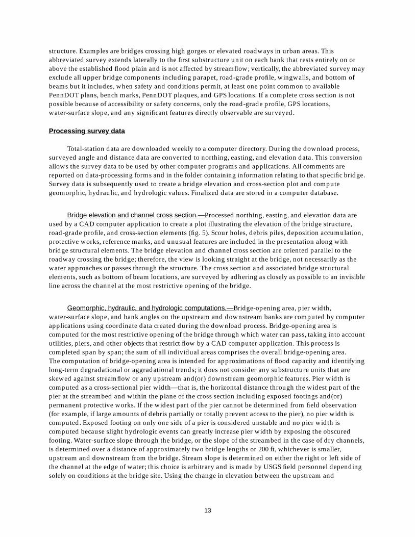
Total-station data are downloaded weekly to a computer directory. During the download process,surveyed angle and distance data are converted to northing, easting, and elevation data. This conversionallows the survey data to be used by other computer programs and applications. All comments arereported on data-processing forms and in the folder containing information relating to that specific bridge.Survey data is subsequently used to create a bridge elevation and cross-section plot and computegeomorphic, hydraulic, and hydrologic values. Finalized data are stored in a computer database.
Bridge elevation and channel cross section.—Processed northing, easting, and elevation data areused by a CAD computer application to create a plot illustrating the elevation of the bridge structure,road-grade profile, and cross-section elements (fig. 5). Scour holes, debris piles, deposition accumulation,protective works, reference marks, and unusual features are included in the presentation along withbridge structural elements. The bridge elevation and channel cross section are oriented parallel to theroadway crossing the bridge; therefore, the view is looking straight at the bridge, not necessarily as thewater approaches or passes through the structure. The cross section and associated bridge structuralelements, such as bottom of beam locations, are surveyed by adhering as closely as possible to an invisibleline across the channel at the most restrictive opening of the bridge.
Geomorphic, hydraulic, and hydrologic computations.—Bridge-opening area, pier width,water-surface slope, and bank angles on the upstream and downstream banks are computed by computerapplications using coordinate data created during the download process. Bridge-opening area iscomputed for the most restrictive opening of the bridge through which water can pass, taking into accountutilities, piers, and other objects that restrict flow by a CAD computer application. This process iscompleted span by span; the sum of all individual areas comprises the overall bridge-opening area.The computation of bridge-opening area is intended for approximations of flood capacity and identifyinglong-term degradational or aggradational trends; it does not consider any substructure units that areskewed against streamflow or any upstream and(or) downstream geomorphic features. Pier width iscomputed as a cross-sectional pier width—that is, the horizontal distance through the widest part of thepier at the streambed and within the plane of the cross section including exposed footings and(or)permanent protective works. If the widest part of the pier cannot be determined from field observation(for example, if large amounts of debris partially or totally prevent access to the pier), no pier width iscomputed. Exposed footing on only one side of a pier is considered unstable and no pier width iscomputed because slight hydrologic events can greatly increase pier width by exposing the obscuredfooting. Water-surface slope through the bridge, or the slope of the streambed in the case of dry channels,is determined over a distance of approximately two bridge lengths or 200 ft, whichever is smaller,upstream and downstream from the bridge. Stream slope is determined on either the right or left side ofthe channel at the edge of water; this choice is arbitrary and is made by USGS field personnel dependingsolely on conditions at the bridge site. Using the change in elevation between the upstream and

14
Figure 5. Bridge elevation and channel cross section of field-viewed bridge.
EXPLANATIONBMS - PennDOT bridge
management systemRGP - road grade profileMRE - mean road elevationTP - top of parapetTFE - top of footing elevationBFE - bottom of footing elevationPK - PK masonry nailUS - upstreamSH - scour holeXS - cross sectionHWM - high-water markUSRA - upstream right abutment

15
downstream surveyed points divided by the horizontal distance through the bridge, the water-surfaceslope is computed and reported in units of “percent slope.” For sites that are described by USGS personnelas having a straight reach, the surveyed point at the bridge may be omitted because this point is used onlyto account for meanders through the bridge opening. A bank angle for each of the upstream anddownstream banks is computed at a representative location by use of two surveyed points collected at thetop of bank and the edge of water. A point approximating top of bank is used when a well definedbankline does not exist and a point located at the bottom of bank is used when water does not contact thebank. By use of these two surveyed points, an angle is computed and reported in “degrees;” zero degreesindicates a horizontal bank and 90 degrees indicates a vertical bank. Angles in excess of 90 degrees arepossible in the case of cantilevered banks; however, for the purpose of this project, all angles greater than85 degrees are considered vertical and are reported as “greater than 85 degrees.”
Quality assuring survey data.—All survey data are checked for completeness and accuracy duringand after the download process. Survey data are checked manually by USGS personnel to ensure thatclosures are within allowable 0.1 ft tolerances. All required attributes are checked for inclusion in thesurvey. All comments are noted on a data-processing form and in the folder assigned to the specific bridge.A computer application, run during data processing, verifies that proper attributes have been used.Any errors detected at this phase are corrected and noted on the data-processing form. A plan view of thebridge site is created and viewed to ensure that the bridge site has been surveyed properly and that allfeatures are present and properly located. A subsequent computer application sorts and rechecks theprocessed data for use in creating opening-area, pier-width, stream-slope, and bank-angle data and cross-section plots. Computer-generated cross-section plots and calculations are manually reviewed by USGSpersonnel for completeness and accuracy to ensure that all coordinates and elevations associated withsurvey attributes have been properly applied and computed by the computer-processing software.
Location Data
The bridge location is determined with a Trimble, code-based GPS (fig. 1) or, if conditions prohibitdata collection with GPS, by digitizing USGS 7.5-minute topographic maps (fig. 1). GPS location data arecorrected subsequent to collection (postprocessed) to improve accuracy, and all locations are stored in acomputer database. Whenever possible, GPS locations are reported for the centerline of the road at thenear abutment; however, locations are reported for alternate substructure units with various offsets in theevent that GPS data collection at the near abutment is not possible or is not representative of the site.All digitized locations are collected at the bridge and stream intersection as indicated on topographicmaps.
Collecting Global P ositioning System data
GPS uses an array of satellites, in fixed orbits around the earth, to determine the latitude andlongitude of a bridge substructure unit in degrees, minutes, and seconds. When possible, 100 positions arecollected at 1-second intervals at each bridge abutment upon arrival at the bridge site. The mean of eachgroup of 100 positions subsequently determines the actual latitude and longitude of a specific abutment.Upon completion of the site assessment, or 1 to 2 hours after initial data collection, 100 additional positionsare collected at the near abutment in an effort to confirm accuracy. If duplicate data collection is notpossible at the near abutment because of loss of communication with satellites and(or) multipath (reflectedsignal) errors, an attempt is made to collect duplicate data at another substructure unit such as the farabutment; in this case, notation is made on the data-collection form describing if, and where, duplicatedata was collected.

16
USGS personnel generally collect GPS data while standing on the centerline of the roadway directlyabove the bridge abutment; however, site conditions commonly require data to be collected streamwardand(or) landward of this position. Notation of the streamward- and(or) landward-offset distance isrecorded in the GPS data logger and stored with the final latitude and longitude of the substructure unit ina computer database. When USGS field personnel determine that the bridge abutments do not accuratelyrepresent the true location of the bridge and stream intersection, GPS data are collected at alternatesubstructure units closer to that intersection; for example, elevated urban bridges, at which the abutmentsmay be miles from the bridge and stream intersection, will generally have GPS data collected at piers onalternate sides of the stream channel. Such cases are recorded in the GPS data logger and noted on thedata-collection form, data-processing form, and in the computer database. The locations at which GPSdata are collected are marked on the bridge with paint and surveyed along with the bridge-geometry inorder to accurately associate the bridge survey with the latitude and longitude.
Collecting digitiz ed location data
When conditions are prohibitive to collecting GPS data because of the available constellation ofsatellites, excessive tree cover, topography, or other impeding conditions, the bridge location isdetermined by digitizing in North American Datum of 1927 (NAD 27) from a USGS 7.5-minutetopographic map. Digitized locations are determined at the center of bridge and stream intersection asindicated on the 7.5-minute topographic map. Sites requiring digitizing are noted as such in a commentfield within the computer database.
Processing Global P ositioning System data
Base stations, located throughout Pennsylvania and adjacent states, are fixed points of referenceused to remove errors that are inherent in the reception of GPS signals. The base station nearest the bridge(generally within 150 km) is determined (Appendix C) and data from that base station are downloaded toa computer via the internet or a modem. GPS data collected at the bridge site also are downloaded to acomputer and subsequently corrected by use of data from the associated base station. This correctionresults in a latitude and longitude accurate to within about 1/10 of a second or about 3 m. Without thiscorrection, accuracy is within the range of approximately 100 m for code-based GPS. The datum used andoutput by the processing software is World Geodetic Survey of 1984 (WGS 84). This WGS 84 datum isconsidered to be equivalent to the North American Datum of 1983 (NAD 83) that is used for processingdigitized locations. Processing results in three separate locations for each bridge, two substructure unitsand a duplicate location for quality assurance. The primary latitude and longitude reported for a bridgesite is for the near abutment. Locations for alternate substructure units are reported when it is determinedthat the primary location fails to meet established criteria.
Processing digitiz ed location data
All digitizing is done in NAD 27 and stored in a computer database. All latitudes and longitudes aresubsequently converted to NAD 83 by means of a commercially available computer software package thatperforms datum shifts automatically within the computer database. Conversion to NAD 83 is required tomaintain consistency with data collected by GPS and to facilitate subsequent GIS data analysis.
Quality assuring location data
At each bridge site, an attempt is made to collect duplicate GPS data for one location with a 1- to2-hour interval between each data-collection attempt. The duplicate data are intended to yield a latitudeand longitude similar to the preceding data but, because of the time element, does so by use of a different

17
constellation of satellites. The change in time and satellite constellation commonly can be used to identifylocations with errors due to reflected signals off buildings or the bridge superstructure termed “multi-path errors.”
Each location, subsequent to postprocessing, is the mean of approximately 100 individual positions.The criteria for determining an acceptable location are the following: (1) the distribution of the positionsmust have a standard deviation equal to or less than 1.5 m (with a standard deviation of 1.5 m,about 95 percent of all positions should be within 3 m of the calculated location) or (2) an initial locationand the associated duplicate location of that feature are within 3 m of each other. If at least one locationdoes not meet the established criteria and if a second attempt has been made to collect GPS data with thesame result, the latitude and longitude are digitized from a topographic map.
Both GPS-determined locations and digitized locations are plotted on GIS spatial data sets tovisually identify any obvious erroneous data (fig. 6). All bridges that are identified by a computer programas having GPS locations plotting greater than approximately 100 m from a bridge and stream intersectionare manually reviewed. This criteria is primarily designed to identify bridges that were potentially
Figure 6. Geographic information system spatial data set showing globalpositioning system locations at bridge abutments.

18
processed with an incorrect datum; however, bridges crossing smaller streams that are not yet included inGIS coverages and bridges crossing streams with expansive floodplains also fail to meet this criteria andare subsequently manually reviewed.
Video-Tape and Captured-Image Data
Video-tape and captured image data are collected at each field-viewed bridge site on the day of thesite visit (fig. 1). Video-tape data and narration by field personnel are intended to give the viewer a briefoverview of site conditions on the day of the site visit as well as to document any site conditions that USGSpersonnel deem as significant, such as stream impacts of the roadway approaches or undermining ofbridge substructure units. Video-tape and captured-image data are not intended to providecomprehensive coverage of all site conditions.
Collecting video data
Each field-viewed bridge site is video taped in a structured, sequential order (Appendix D).The taping includes narration by field personnel and describes site characteristics of structural andgeomorphic significance. Field personnel begin and end each video by recording the bridge number anddate of video, usually shown on a large, erasable whiteboard. Video of the bridge site begins by firstlooking at the upstream and downstream channels from the bridge. Collection of video data for theupstream and downstream channels is accomplished by standing on the bridge deck above the respectiveface of the bridge or by standing in an equivalent position if no access is available to the bridge deck.Video taping starts with a view of the near roadway approach, then pans out towards the channel andaround to the far roadway approach; this provides coverage of channel and overbank areas andconditions. Taping continues from the far roadway approach and pans down and across the face of thebridge, ending with another view of the near roadway approach. Panning down and across the bridge faceshows debris and(or) any feature directly at the face. Field personnel then move out into the channelapproximately two bridge lengths or 200 ft, whichever is less, upstream, and then subsequentlydownstream. From these locations, a 360-degree pan is taped, starting and ending looking away from thebridge at the upstream and, subsequently, downstream channel. Field personnel pause momentarily onthe view of each bridge face to facilitate the capture of an image later in the processing. After routineprocedures are completed, field personnel are free to continue with additional taping as required in orderto document bridge-site conditions and obtain the best possible image of the bridge. Often, additionaltaping is required to document an oblique view of the bridge face or significant conditions that are notvisible from standard locations.
Processing video data
Selected video images are captured from video tape, enhanced, edited, and subsequently stored in acomputer directory by use of commercially available software. An attempt is made to provide an image ofthe upstream opening of the bridge (fig. 7). If it is not possible to capture an image of the upstream bridgeopening because of unfavorable site conditions, such as poor lighting or dense vegetation, the followingimages are captured in order of highest priority:
1. downstream bridge opening
2. oblique shot of the upstream bridge face
3. oblique shot of the downstream bridge face

19
Additional images indicative of existing or potential structural stability problems also are captured asrequired to fully document significant site conditions. Captured images are enhanced with commerciallyavailable photographic-processing software in order to maximize clarity and edited to add associatedinformation such as bridge number, date, and a description of the image. Edited images are stored in aseparate computer directory from the raw, unedited images. In the event that an image does not passinspection or if an error is detected in the quality-assurance process, the original image can be used again.
Quality assuring video data
Video-tape data for approximately 10 percent of all bridge sites are reviewed subsequent tocollection in the USGS office. Office review of video-tape data is to confirm the accuracy of fieldprocedures and data elements collected as well as to confirm the quality and operation of videoequipment. Equipment malfunctions such as inoperable audio or dirty recording heads are difficult todetect in the field and must be determined by subsequent review of collected data. All video imagescaptured from the video tape are reviewed for quality of image and correctness of information added tothe image during the processing phase.
Figure 7. Video image of upstream face of field-viewed bridge.

20
Office-Re viewed Bridg e Sites
PennDOT-supplied office data are being compiled for approximately 500 bridges throughout thecourse of the study. Office-reviewed bridge sites are not visited by USGS personnel and rely solely onPennDOT-supplied data. Data for bridges that fall into the office-reviewed category are recorded on the“Bridge and Channel Characteristics at Office-Reviewed Bridge Sites” form. A detailed description of thisform and its components is presented in Appendix E.
Scour assessments based on office-reviewed data are being conducted for two categories of bridgesites. The first category includes bridges built or extensively renovated after 1982. In 1982, PennDOTrevised the requirements for hydrologic and hydraulic reports resulting in substantially more databecoming available for bridges constructed after this time. Data sources used to complete the assessmentof office-reviewed bridge sites include PennDOT Inspection Reports and(or) PennDOT UnderwaterInspection Reports, hydrologic and hydraulic reports, foundation reports, foundation approval letters,plan and design data, and photographs documenting site conditions. These data are used to characterizethe bridge site, as well as to assist PennDOT in meeting the 1988 FHWA mandate. The second categoryincludes bridges built before 1983 but at which, because of hydraulic conditions or safety concerns,greater than 50 percent of the substructure units are inaccessible to USGS personnel for data collection inthe field. For this second category of bridge sites, all available PennDOT information is reviewed;however, data sources are frequently limited to the most recent PennDOT Inspection Report,Bridge Management System data, and, if available, the most recent PennDOT Underwater InspectionReport. Because of the lack of data to sufficiently characterize the bridge site for this second category,the primary objective is to assist PennDOT in satisfying the 1988 FHWA mandate. No video or survey dataare compiled for office-reviewed bridge sites.
Bridge and Channel-Characteristics Data
The information and data in this section include geomorphic, sediment, vegetative, and hydraulic-characteristics data collected from PennDOT data sources and compiled by USGS personnel. These dataare qualitative and provide an indication of channel stability and scour condition as well as a baseline towhich future inspections can be compared. Office-reviewed bridge data represent bridge-site conditionsfor the time and date that data was collected by PennDOT or PennDOT contract personnel. The date of alldata sources used by USGS personnel is recorded on the data-collection form to document this time frame.
Compiling Bridg e and Channel-Characteristics Data
Bridge and channel-characteristics data for office-reviewed bridge sites are housed in PennDOTDistrict Engineering offices, offices of consultant engineers, and the offices of local bridge ownersthroughout the Commonwealth of Pennsylvania. USGS personnel travel to these locations to record therequired data as they become available.
Office-reviewed data are reported on a form designed to promote a methodical description of thebridge site as described in detail in Appendix B. This form includes data entry by use of multiple menuoptions for each variable and narrative comment fields. For bridges that are office reviewed, bridge andchannel-characteristics data similar to those at field-viewed sites are compiled. Additionally,design information such as recurrence interval, discharge, elevation, and maximum velocity for the designflood; discharge, elevation, maximum velocity, and calculated scour depths for the 100-year flood;and more specific descriptors of substructure units are compiled when available. Flagged data fields(noted by an asterisk placed at the data-entry field) indicate those data required to meet the 1988 FHWA

21
mandate. Data fields that are boxed may commonly have no data available and are filled in as possible.These boxed fields are not used in the computation of the Code and Rating and are used primarily tobetter define the bridge site in terms of channel stability. Data sources for office-reviewed bridge sitesinclude plan data, design drawings, hydrologic and hydraulic reports, foundation reports and(or)foundation approval letters, most current PennDOT Inspection Reports, PennDOT Underwater InspectionReports (if applicable), and all available photographs. All data sources used for the assessment of office-reviewed bridge sites are collected by PennDOT personnel according to PennDOT protocols. PennDOTdata such as flood-recurrence interval and discharge data, while similar to USGS data, are not compared tothat determined by the USGS.
Upon completing compilation of the bridge and channel-characteristics data, USGS personnelassign a final designation indicating whether a site visit is warranted to verify or collect more extensivedata. PennDOT personnel are consulted throughout the data-compilation process and their input isconsidered in making this final designation. Bridge sites constructed or renovated before 1983 (limiteddata) where data indicate highly unstable channels or substantial scour-related problems are examples ofoffice-reviewed bridge sites that may warrant a site visit by USGS field personnel. Additional informationsuch as surface cover near the bridge, upstream and downstream bed material, vegetative cover near thebridge, and other data not readily available from older, office-reviewed data are collected at these sites andincorporated into the database to more accurately represent problematic bridge sites.
Processing Bridg e and Channel-Characteristics Data
Bridge and channel-characteristics data for office-reviewed bridge sites are entered into a computerdatabase upon return to the USGS office. This database entry program differs from that for field-viewedbridge sites because of the required changes in the format of the data-collection form and the source of thecompiled data. Questionable entries are verified during data entry by the USGS personnel that reviewedand compiled the data and(or) PennDOT personnel as required.
Quality Assuring Bridg e and Channel-Characteristics Data
PennDOT personnel are consulted at the time of data compilation to verify any questionablecharacteristics or data entries. During data entry, USGS personnel ensure that all abbreviations areexpanded or are consistent with established guidelines for acceptable abbreviations, all required entriesare in place, and questionable data are verified by USGS personnel present at the time of the datacompilation and by PennDOT personnel as required. All bridge and channel-characteristics data aresubsequently reviewed again before being archived. In this phase, USGS personnel check the computerdata entries against the original data-collection form to ensure that notes have been transcribed correctly.
Location Data
Locations for office-reviewed bridge sites are digitized from USGS 7.5-minute topographic maps.The digitized location is the center of the bridge-stream intersection. All digitizing is done in NorthAmerican Datum 1927 then converted to North American Datum 1983 by means of a commerciallyavailable software package. Locations are plotted on GIS road and stream coverages to identify any errorscaused by incorrect datums or equipment malfunction.

22
PROCEDURE FOR DRAINAGE-BASIN DESCRIPTION AND FLOOD-DISCHARGECOMPUTATIONS BY USE OF A GEOGRAPHIC INFORMATION SYSTEM
Drainage-basin characteristics upstream from the bridge site are compiled for nearly all sites bymeans of various GIS computer applications and USGS topographic maps in order to assist PennDOTin interpreting data and prioritizing remedial actions as required. Drainage basins are delineated, for mostsites, by use of a digital elevation model (DEM) with available stream and topographic GIS coverages.Drainage basins in counties that have surficial carbonate rock are manually-delineated from USGStopographic maps because of uncertainties in drainage patterns caused by karst topography.Drainage basins inside metropolitan Philadelphia are identified from previously published data ormanually delineated from USGS topographic maps. Manually delineated drainage-basin boundaries aredigitized and used along with those obtained by GIS methods to develop basin criteria. All drainage-basinareas computed by GIS methods are compared to areas determined from USGS topographic maps toensure accuracy of the automated system of computation. Bridge sites are located within a drainage basinby means of GPS or digitized latitude and longitude data.
A statewide GIS-coverage database has been compiled that includes carbonate, crystalline,siliciclastic, and unconsolidated rock types; land use; soil types; drainage-basin boundaries; flood regionsand precipitation index maps; and skew coefficients for flood-frequency computations. From thesecoverages, percentage of forest cover, percentage of urbanized area, surface area of reservoirs,percentage of carbonate geology, and mean basin slope are determined for the drainage basin upstreamfrom the bridge site.
Peak flood discharges are estimated for the 10-, 25-, 50-, 100-, and 500-year recurrence intervals byuse of as many as four computational methods based on location of the bridge site and the size of thedrainage basin in which the bridge site is located (table 1). Bridge sites are determined as being outside orinside of the Philadelphia metropolitan area on the basis of the incorporated area of the city ofPhiladelphia, Philadelphia County, Pa. (Federal Emergency Management Agency, 1996).
Table 1. Methods used for estimation of flood-frequency discharges
[USGS 82-21, U.S. Geological Survey Water-Resources Investigations 82-21,Evaluation of the Streamflow Data Program in Pennsylvania; FIS, Federal Emergency ManagementAgency, Flood Insurance Study; PSU-IV, Penn State University equation IV; <, less than; >, greater than;≤, less than or equal to; Q10, 10-year flood-frequency discharge; Q25, 25-year flood-frequency discharge;Q50, 50-year flood-frequency discharge; Q100, 100-year flood-frequency discharge; Q500, 500-yearflood-frequency discharge]
LocationDrainage basin area
(square miles)Flood-frequency discharge Method used for estimation
Outside metropolitan Philadelphia area>500 Q10, Q50, Q100, Q500 FIS< 500 Q10, Q25, Q50, Q100, Q500 USGS 82-21>150 Q10, Q25, Q50, Q100, Q500 USGS streamflow-measurement station data≤150 Q10, Q25, Q50, Q100, Q500 PSU-IV
Inside metropolitan Philadelphia areaAll basins Q10, Q50, Q100, Q500 FIS
>150 Q10, Q25, Q50, Q100, Q500 USGS streamflow-measurement station data≤150 Q10, Q25, Q50, Q100, Q500 PSU-IV

23
Inside the Philadelphia metropolitan area, three computational methods are used: transference ofFederal Emergency Management Agency (FEMA), Flood Insurance Study data (FIS) (Federal EmergencyManagement Agency, 1976-1996), the Penn State University regional equation method number IV(PSU-IV) (Aron and Kibler, 1981), and transference of USGS streamflow-measurement station data(Flippo, 1977). FIS data are used for bridge sites within the metropolitan Philadelphia area in all sizes ofdrainage basins. Peak discharges for most recurrence intervals are extrapolated from the locality of the FISstudy to bridge sites within the same drainage basin by the use of drainage-area ratios; the 25-year peakdischarge, however, is not estimated using FIS data in this area. Methods used to compute discharges inthe FIS studies are identified in the individual FIS study reports and are not presented with the dischargedata computed for the bridge site. The PSU-IV method uses regional equations to determine the10-, 25-, 50-, and 100-year peak discharges for bridge sites with drainage basins of less than or equal to150 mi2. USGS streamflow-measurement station data are used to estimate the 10-, 25-, 50-, 100- and500-year peak discharges for bridge sites with drainage basins of greater than 150 mi2. Under this method,peak discharges are determined for streamflow-measurement stations located within the same drainagebasin as the bridge site. These peak discharges are subsequently extrapolated to the bridge site by use ofdrainage-area ratios.
Outside of the Philadelphia metropolitan area, four computational methods are used to estimatepeak discharges: FIS, PSU-IV, USGS streamflow-measurement station data, and the USGS 82-21 regionalequation method (Flippo, 1982). The FIS, PSU-IV, and USGS streamflow-measurement station datamethods are applied in a similar manner to this region with the exception that FIS data is only applied todrainage basins greater than or equal to 500 mi2. In addition to FIS, PSU-IV, and USGS streamflow-measurement station data methods, the USGS 82-21 regional equation method is used for bridge sites withdrainage basins less than 500 mi2 for estimates of the 50- and 100-year peak discharges; the 10-, 25-,and 500-year peak discharges are subsequently calculated from extrapolation of the 50- and 100-year peakdischarges.
Peak discharges are determined for all USGS streamflow-measurement stations with greater than10 years of data available with drainage basins of greater than 150 mi2. The computed data for the Q10,Q25, Q50, Q100, and Q500 values are extrapolated to bridge sites within 0.3 to 3.0 times the drainage basinarea from the location of the streamflow-measurement station. Exceeding the 0.3 to 3.0 times range indrainage basin area will result in increased error because of inherent changes within the drainage basinsuch as basin slope, land use, and(or) other possible variables. If a stream reach has two or morestreamflow-measurement stations within a given proximity such that the computed statistics will overlapfor areas along that reach, statistics for the area of data overlap were computed from the streamflow-measurement station with the longest period of record (Ehlke and Reed, 1999).

24
PROCEDURE FOR COMPUTATION OF SCOUR-CRITICAL BRIDGE INDICATOR CODE ANDSCOUR ASSESSMENT RATING FOR BRIDGE SCOUR ASSESSMENT
The Code and Rating use PennDOT derived algorithms (Bryan Spangler, written commun., 1998) torate bridge sites for observed and potential scour on the basis of USGS field observations and(or) existingPennDOT data. While the Code is primarily directed at satisfying the 1988 FHWA mandate, the Code andRating are designed to work in conjunction with each other. The Code and Rating are computed on thebasis of site conditions observed on a specific date and time; hydrologic events subsequent to datacollection can significantly alter the site conditions that determine the Code and Rating.
Scour -Critical Bridg e Indicator Code
The Scour-Critical Bridge Indicator Code indicates the vulnerability of the bridge to future scour(Appendixes F and G). The Code refers to the FHWA code (Federal Highway Administration, 1989) and isbased on the PennDOT interpretation of that code (Bryan Spangler, written commun., 1999). The Code isselected from a range between 9 and 2 with each code divided into a subset of cases. Codes and cases arenot a straight-forward numeric sequence, they describe a specific type of site condition only; for example,a code 6 is not necessarily better or worse than a code 5. A field-viewed or office-reviewed substructureunit can be coded only if data are available for the following data fields: substructure-unit type;substructure-unit foundation type; scour condition; change since last inspection; streambed material nearthe substructure unit or, when not available, under-the-bridge primary bed material; condition of counter-measures at substructure unit if any; recommendations of possible countermeasures under the bridge,if any; evidence of movement; and BMS item C05A (Structural Configuration and Material Used for MainUnit and Approach Span). A substructure unit may meet the criteria for more than one code and(or) casewithin a code; however, codes are ranked according to priority as detailed in Appendixes F and G.Therefore, all substructure units receive only one code but can have multiple cases presented within thatcode. The overall bridge structure only receives a code value, and no case values are presented.This overall code assigned to the entire bridge structure is the highest priority code assigned to anyassessed substructure unit. If insufficient data or site conditions prohibit the computation of the Code,the bridge will automatically be given a code of 6; a code of 6 indicates further review of the bridge site isrequired by PennDOT personnel. The Code is used only in conjunction with the Scour Assessment Rating;because the Code primarily addresses the potential for future scour and the Rating primarily addressescurrent observed scour conditions, as stand-alone data, they may misrepresent the bridge site.
Scour Assessment Rating
The Scour Assessment Rating is composed of component values for each substructure unit of abridge structure and selected site conditions that are combined to provide an overall bridge rating from0 to 100 (Appendixes H and I). This rating indicates the observed-scour condition of a bridge site and canbe generally interpreted as: >80 = good, >50 = average, 50 to 20 = potential problems, and <20 = poor;however, all bridge-site data must be reviewed before making this interpretation because the Rating isdesigned to represent bridge-site conditions only in conjunction with other data. A field-viewedsubstructure unit can be rated only if data are available for the following data fields: substructure-unittype; substructure-unit foundation type; scour condition; evidence of movement; wingwall condition,if present; and condition of countermeasures at the substructure unit, if any. Rating an entire field-viewedbridge site requires that all applicable substructure units are rated and that the following site-conditiondata are available as defined in appendixes A and E: trapping potential, debris potential, debrishorizontal and vertical location, and evidence of pressure flow. Substructure units that do not meet thecriteria for scour assessments are not rated and do not contribute to the overall bridge rating; for example,

25
expansive bridges that carry elevated roadways are only rated on those substructure units that are incontact with streamflow. Rating an office-reviewed bridge site requires that all substructure units are ratedin a similar manner to those with field-collected data and that the site-condition data fields for debrispotential and evidence of pressure flow are complete. Substructure units for field-viewed and office-reviewed bridge sites that cannot be rated because of missing or contradictory data receive a rating of“999.” Because the substructure units are components of the overall bridge structure, if a substructure unitreceives a “999” the overall structure cannot be rated and also receives a rating of “999.” Both the Codeand the Rating are required to adequately portray site conditions and vulnerability to scour because theCode and the Rating are designed to look at different aspects of the bridge site; as stand-alone data,the Code and Rating may misrepresent the bridge site.
Because of differences in data-collection methods between PennDOT and the USGS (for example,PennDOT design and construction information in contrast to USGS field observation), PennDOT BMSdata are compared with data collected by USGS personnel for substructure-unit type and substructure-unit foundation type to determine the data source used in computation of the Code and Rating.This comparison serves to give an accurate representation of site conditions that may be otherwiseerroneous and(or) incomplete. For field-viewed sites at which PennDOT information is incomplete, or anindication of contradictory data is present either within or between USGS and PennDOT data sources, thebridge is flagged or does not receive a Code and(or) Rating. Office-reviewed bridge sites rely only onPennDOT data and all discrepancies observed within PennDOT data sources are corrected at the time ofoffice review.
Pennsylv ania Depar tment of T ranspor tation Re view
All bridge-site data generated by the USGS undergo a review by experienced PennDOT bridge-inspection personnel before final assignment of the Code and Rating. This review enables PennDOTpersonnel to provide an alternative Code and Rating, if needed, for a particular bridge site on the basis ofstructural conditions and(or) historical evidence that may not be known or available to the USGS at thetime of Code and Rating computation. USGS personnel work with PennDOT personnel during this phaseto resolve all discrepancies.
POTENTIAL APPLICATIONS OF DATA
The field-viewed and office-reviewed bridge-site data, along with the Scour-Critical BridgeIndicator Code and Scour Assessment Rating, have several potential applications. These applications mayinclude, but are not limited to, prioritizing bridge sites in terms of potential or observed scour,GIS analysis, determination of relation among data variables, and individual and multiple problemanalysis. Applications may consider spatial relations such as the relation of multiple bridges along astream reach or within a specific drainage basin as well as the relations among specific data such as therelation of scour condition to date of bridge construction. The scope of this project requires mixedpopulations of data to exist; subsequent analysis should, therefore, confirm that data-collection proceduresand data sources are consistent with the requirements of that analysis before it is undertaken.
Prioritizing Bridg e Sites in T erms of P otential or Obser ved Scour
Data collected for field-viewed and office-reviewed bridge sites are compiled in a computerdatabase that may be queried to retrieve significant information. This information may be used toprioritize bridge sites in terms of potential or observed scour. For example, bridges may be prioritized

26
according to the Code. This list may then be weighted by such variables as the Rating, the drainage areaupstream from the bridge, and the bridge-opening area. Prioritizing bridges in terms of potential orobserved scour assists PennDOT personnel in determining potential maintenance and remedial actions.
Geographic Inf ormation System Anal ysis
GIS analysis allows the user to generate spatial data sets (SDS) showing the location of bridges alongwith selected characteristics. SDS are, essentially, layers of data, stacked one on top of the other, with eachlayer, or coverage, representing a different variable. All data within the coverage corresponds to a specificlocation such as a latitude and longitude. For example, data collected for each bridge corresponds to thelatitude and longitude of that bridge within a computer database. This location enables the user to querythe database and create coverages for specific aspects of each bridge site. An example analysis mightattempt to imply how urban development within a specific county is affecting bridges spanning a specificstream. The analysis might first create a coverage showing the county boundary. Then a coverage showingthe stream, its tributaries, and the drainage basin would be added. Finally, a coverage of all bridgesassessed in that county that also span the stream and tributaries in question would be added. Bridgesassessed in Chester County, Pa., that span Brandywine Creek and its tributaries are shown in figure 8.This SDS, could be created to determine if sufficient data exists and if the data are consistent with theneeds of the analysis. For example, there might not be enough bridges crossing the stream to providesufficient data for an analysis. This SDS could subsequently be expanded to show the physiographicprovinces and(or) only those bridges with footing exposure. Once the required coverages are assembledinto the appropriate SDS, a map may be printed for field use.
Determination of Relation Among Data V ariab les
Data variables may be analyzed by statistical and(or) other methods to identify any significantrelation between those variables. For example, all bridges with footing exposure (advanced or seriousscour condition) may be analyzed with respect to the date of bridge construction (from PennDOT BMSdata) and the attack angle on the substructure unit. This analysis might show that footing exposure is moreor less common with one variable than the other, or possibly that there is no relation at all between any ofthe variables. By identifying any significant relations between scour and(or) other data variables,PennDOT may subsequently prioritize maintenance and required remedial actions by looking atsignificant variables.
Individual Pr oblem Anal ysis
Data, when queried from a computer database, may be used for a statistical analysis of individualproblems. For example, a list of bridges may be generated to show all bridges with footing exposure at oneor more substructure units within a specific physiographic province. This sample may then be comparedto similar samples from other physiographic provinces. This comparison may subsequently lead to acorrelation of scour condition to a specific physiographic province.
Multiple Pr oblem Anal ysis
Data from a computer database also may be queried for multiple problem analysis. This statisticalanalysis may be used in order to determine which site characteristic is more significant in terms ofpotential and(or) observed scour condition. For example, the high-flow angle of approach and the debrisaccumulation at the bridge might be queried for bridges within a specific physiographic province.

27
Statistical analysis of these data may subsequently prove that either the high-flow angle of approach or thedebris accumulation is of greater significance to scour condition at bridges within that specificphysiographic province.
SUMMARY
Scour at bridge foundations and channel instability during high flows of rivers and streams areprimary causes of bridge failure. In response to the scour-related failure of several bridges in the UnitedStates, the U.S. Department of Transportation, Federal Highway Administration (FHWA), issued amandate requiring States to conduct assessments of scour vulnerability at all public bridges over water.The U.S. Geological Survey (USGS) entered into a cooperative agreement with the PennsylvaniaDepartment of Transportation (PennDOT) to create procedures and conduct scour and channel-stabilityassessments to aid PennDOT in complying with the FHWA mandate.
Figure 8. Geographic information system spatial data set showing bridges in Chester County,Pennsylvania, spanning Brandywine Creek and its tributaries.

28
Scour assessments are conducted for two categories of bridge sites, field-viewed bridge sites andoffice-reviewed bridge sites. USGS personnel acquire geomorphic, hydraulic, and hydrologic data that areindicative of the existing or potential effects of stream processes on the bridge or stream channel for thesesites. Ancillary data are collected and compiled in order to assist in interpretation of data and to create abaseline against which future assessments can be measured.
Characteristics of the drainage basin upstream from each bridge and flood-frequency discharges arecomputed and described using GIS data sets and USGS topographic maps. Drainage-basin characteristicsinclude percentage of forest cover, percentage of urbanized area, drainage area, surface area of reservoirs,percentage of carbonate geology, and the mean basin slope. Flood-frequency discharges are computed foreach site using several computational methods. These methods vary depending on bridge-site locationand drainage-basin size. Regional regression equations are compared and modified on the basis offindings from USGS streamflow-measurement stations.
Using data acquired from USGS site visits and(or) PennDOT data sources, a Scour-Critical BridgeIndicator Code and Scour Assessment Rating are computed for each site. These Codes and Ratings arenumeric rankings based on PennDOT-developed algorithms that include a variety of significant factorsthat influence channel stability and scour vulnerability of bridges. The completed Codes and Ratings arereviewed by PennDOT personnel before final assignment of Code and Rating values. The primarypurpose of the Code is to satisfy the FHWA mandate; the Rating assists in the qualification andinterpretation of the Code. The drainage-basin characteristics and flood-frequency discharges assistPennDOT in the interpretation of the Code and Rating and provide a baseline against which futureassessments can be measured.
Collected data along with computed Code and Rating have several potential applications.These include prioritizing bridge sites in terms of potential or observed scour to assist in maintenance andremedial actions, GIS analysis, analysis of relations among variables, multiple problem analysis,and individual problem analysis. These applications can assist PennDOT in the interpretation of the dataand in prioritizing maintenance activities and possible remedial actions.

29
REFERENCES CITED
Aron, G., and Kibler, D.F., 1981, Procedure PSU-IV for estimating design flood peaks on ungaged Pennsylvaniawatersheds: Institute of Research on Land and Water Resources, FHWA/PA 81-013, 211 p.
Berg, T.M., Barnes, J.H., Sevon, W.D., Skema, V.W., Wilshusen, J.P., Yannacci, D.S., 1989, Physiographic provincesof Pennsylvania: Harrisburg, Pa., Pennsylvania Department of Environmental Resources, Bureau ofTopographic and Geologic Survey Map 13.
Doheny, E.J., Helinsky, B.M., and McGregor, R.A., 1996, A technique for preliminary appraisal of potential andobserved scour as applied to state-maintained highway bridges in Maryland: U.S. Geological Survey Open-File Report 95-135, 75 p.
Ehlke, M.H., and Reed, L.A., 1999, Comparison of methods for computing streamflow statistics for Pennsylvaniastreams: U.S. Geological Survey Water-Resources Investigations Report 99-4068, 80 p.
Federal Emergency Management Agency, Federal Insurance Administration, 1976-1996, Flood insurance study,(Published for individual municipalities throughout Pennsylvania).
Federal Highway Administration, 1989, Recording and coding guide for the structure inventory and appraisal of thenation's bridges: Federal Highway Administration Report FHWA-ED-89-044, 115 p.
Flippo, H.N., Jr., 1977, Floods in Pennsylvania: Commonwealth of Pennsylvania, Department of EnvironmentalResources Bulletin 13, 59 p.
_____1982, Evaluation of the streamflow data program in Pennsylvania: U.S. Geological Survey Water-ResourcesInvestigations 82-21, 56 p.
Lagasse, P.F., Schall, J.D., Johnson, F., Richardson, J.R., and Chang, F., 1990, Stream stability at highwaystructures: Federal Highway Administration Hydraulic Engineering Circular 20, Publication FHWA-IP-014,195 p.
Pennsylvania Department of Transportation, 1993, Bureau of Design, Bridge management system (BMS),coding manual, office version: Pennsylvania Department of Transportation Publication 100A, 123 p.
_____1994, Bureau of Design, Design manual part 2: Pennsylvania Department of Transportation, chap. 10, 145 p.
Richardson, E.V., Harrison, L.J., Richardson, J.R., and Davis, S.R., 1993, Evaluating scour at bridges (2d ed.):Federal Highway Administration Hydraulic Engineering Circular 18, Publication FHWA-IP-90-017, 236 p.
Simon, A., 1989, A model of channel response in disturbed alluvial channels: Earth surface processes andlandforms, v. 14, no. 1, p. 11-26.
Wolf, P.R., and Brinker, R.C., 1994, Elementary surveying (9th ed.): New York, Harper Collins College Publishing,760 p.

31
A
APPENDIX APROCEDURES FOR COMPLETING THE “B RIDGE AND CHANNEL
CHARACTERISTICS AT FIELD-VIEWED BRIDGE SITES” F ORM
AND THE “A DDENDUM TO FIELD FORM FOR NON-ACCESSIBLE
SUBUNITS” F ORM
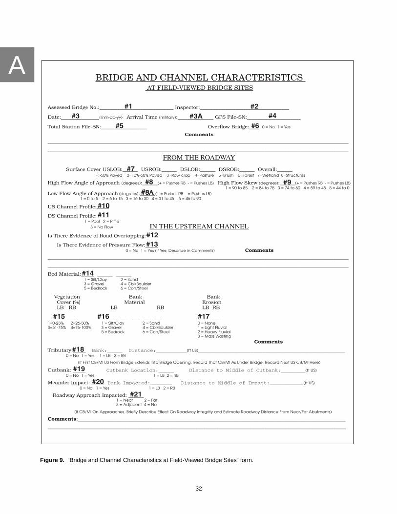
AA
32
Figure 9. “Bridge and Channel Characteristics at Field-Viewed Bridge Sites” form.

A
33
Figure 9. “Bridge and Channel Characteristics at Field-Viewed Bridge Sites” form—Continued.

AA
34
Figure 9. “Bridge and Channel Characteristics at Field-Viewed Bridge Sites” form—Continued

A
35
Figure 9. “Bridge and Channel Characteristics at Field-Viewed Bridge Sites” form—Continued

AA
36
Figure 9. “Bridge and Channel Characteristics at Field-Viewed Bridge Sites” form—Continued.

A
37
Figure 9. “Bridge and Channel Characteristics at Field-Viewed Bridge Sites” form—Continued.

AA
38
Figure 9. “Bridge and Channel Characteristics at Field-Viewed Bridge Sites” form—Continued.

A
39
Figure 9. “Bridge and Channel Characteristics at Field-Viewed Bridge Sites” form—Continued

AA
40
Figure 9. “Bridge and Channel Characteristics at Field-Viewed Bridge Sites” form—Continued.

A
41
Figure 9. “Bridge and Channel Characteristics at Field-Viewed Bridge Sites” form—Continued.

AA
42
Figure 9. “Bridge and Channel Characteristics at Field-Viewed Bridge Sites” form—Continued.

A
43
Figure 9. “Bridge and Channel Characteristics at Field-Viewed Bridge Sites” form—Continued.

A
44
PROCEDURES FOR COMPLETING THE “BRIDGE AND CHANNEL CHARACTERISTICSAT FIELD-VIEWED BRIDGE SITES” FORM
The information and required data elements collected according to this appendix includegeomorphic, sediment, and hydraulic data elements. Each entry is recorded directly onto the data-collection form. For items below that list the data-collection location as two bridge lengths (fig. 10)upstream or downstream from the structure, this distance may be reduced to 200 ft in the case of expansivebridges. Distances, relative to the bridge, are measured along the stream channel, not as a straight line.Significant features directly observable but beyond 200 ft from the bridge are to be included on the data-collection form. Any item that receives an entry of “Other” is to be discussed in the comment field that isprovided in the vicinity of that item and(or) have the appropriate sketch completed. PennDOT items inparentheses refer to items modified from or taken directly from PennDOT publication 100A (PennsylvaniaDepartment of Transportation, 1993).
The Follo wing Items are to be Recor ded in the V ehic le:
1. Assessed Bridge Number (PennDOT item A01)
The assessed bridge number is the 14-digit structure-identification number according to item A01 ofBMS Pub 100A on the day of the field visit. This number is provided by PennDOT and serves toidentify a bridge location and to indicate the bridge owner.
2. Inspector
The inspector is the USGS person collecting the data. The format for entry includes the person’s firstinitial, middle initial (if appropriate), and last name.
Figure 10. Bridge length.
Wingwall
Wingwall
Bankline
Abutment
Pier
Bridge Deck
One Bridge Length
Stre
am

A
45
3 and 3A. Inspection Date and Time of Arrival on Site
The date is the month, day, and year of the site assessment. The time that field personnel arrive at abridge site is recorded in military time (24-hour system).
4. GPS File Name and Serial Number
The GPS file name consists of eight characters. The first two characters are the county code indicatingwhere the GPS data is collected (for example, 22 would indicate that data was collected in DauphinCounty. Appendix A of BMS Pub 100A lists codes for all counties within Pennsylvania). Charactersthree through five represent the Julian Day on which the GPS data was collected (for example, day 152is representative of June 1). Character six indicates the year in which the GPS data is collected(for example, 8 indicates the data was collected during 1998). The seventh character is a unique letterassigned to each field team. This letter is used to distinguish between files collected by different fieldteams on the same day. The eighth character is a numeral that is used to distinguish between bridgesassessed on the same day by an individual field team. The numbering sequence begins at one at thestart of each day and increases by increments of one as each subsequent bridge is assessed during aparticular day. This item ends with a dash (-) and the last two digits of the serial number for the GPSunit that has collected the data. Examples of this file naming procedure for Team A working inDauphin County on June 1, 1994, using GPS unit #73 would be 221524A1-73 for the first file of the dayand 221524A2-73 for the second file of the day. Team B may collect GPS data in the same county andon the same day however the “B” in their GPS file names would distinguish between the files collectedby other teams.
5. Total Station File Name-Serial Number
A six-character file name is assigned to each total station file. This item utilizes the same file-namingconvention as that discussed for the GPS data, including the last two digits of the total station serialnumber, with the exception that the county code is omitted.
6. Is This An Overflow Bridge
Entries are 0 = no or 1 = yes, indicating whether or not the bridge is an overflow bridge. An overflowbridge is a structure that is located on the flood plain and receives streamflow only during overbank-flow conditions.
The Follo wing Items are to be Recor ded Fr om the Road way On or Near the Bridg e Deck:
7. Surface Cover
Surface cover in the immediate vicinity of the bridge is described using options from the eight surface-cover categories (1 = >50% paved, 2 = 10%-50% paved, 3 = row crop, 4 = pasture, 5 = brush, 6 = forest,7 = wetland, and 8 = structure) listed on the field form. Surface cover, for the upstream right, upstreamleft, downstream right, and downstream left quadrants, is described within an area defined by twobridge lengths upstream and downstream and up to two bridge lengths landward of the bridge.The category that best describes the overall ground cover of the bridge site also is recorded.
8 and 8A. High Flow and Low Flow Angles of Approach
Standing near the bridge deck, field personnel determine the direction from which bankfull flow (highflow) and low flow approach the bridge location and the direction along which bankfull flow and lowflow exit the bridge location. The approach angles are a measure of the angle created by theintersection of these two imaginary lines (figs. 11 and 12). These parameters are not a measure of theattack angles on the bridge. They are a comparison of the upstream and downstream reaches. Entriesare 1 = 0 to 5, 2 = 6 to 15, 3 = 16 to 30, 4 = 31 to 45, or 5 = 46 to 90 degrees. Flow paths directed towardthe left bank are recorded with the angle category preceded by a minus (-) sign. Flow paths directedtoward the right bank are recorded with the angle category; a positive sign is assumed.

A
46
Bankline
Low-flow Channel
Abutment
Wingwall
Wingwall
Bridge
Road
Bankline
Bankline
Bankline
Bankline
Stre
am
Deck
Bankfull Channel
Ω
Ω - High-flow approach angle
Figure 11. High-flow approach angle.
Bankline
Low-flow Channel
Abutment
Wingwall
Wingwall
Road
Bankline
Bankline
Bankline
Bankline
Bankfull Channel
τ
Bridge
Deck
Stre
am
- Low-flow approach angleτ
Figure 12. Low-flow approach angle.

A
47
9. High Flow Skew to Upstream Bridge Face
Standing on the bridge deck, field personnel record the angle at which bankfull flows (high flows)approach the upstream face of the bridge (fig. 13). Entries are 1 = 90 to 85, 2 = 84 to 75, 3 = 74 to 60,4 = 59 to 45, or 5 = 44 to 0 degrees. Flow paths directed toward the left bank are recorded with theangle category preceded by a minus (-) sign. Flow paths directed toward the right bank are recordedwith the angle category; a positive sign is assumed.
10. Upstream Channel Profile
This item indicates if the stream, between the bridge and two bridge lengths upstream of the bridge,when practical, is dominated by a pool (1) or a riffle (2). When the stream is dry or consists ofnonflowing, isolated pools, an entry of 3 = no flow.
11. Downstream Channel Profile
This item indicates if the stream, between the bridge and two bridge lengths downstream of thebridge, when practical, is dominated by a pool (1) or a riffle (2). When the stream is dry or consists ofnonflowing, isolated pools, an entry of 3 = no flow.
The Follo wing Items Are to be Recor ded in the Upstream Channel:
The upstream channel is defined as an area beginning at the upstream end of the upstream wingwallsand extending to a distance of two bridge lengths upstream. If no wingwalls are present, the toe of theroad berm is used as downstream ends of the upstream channel.
Figure 13. High-flow skew angle.
Road
Wingwall
Wingwall
Bankline
Abutment
Stre
am
φBridge Deck
φ - High-flow skew angle

A
48
12. Is There Evidence of Road Overtopping
Field personnel inspect the vicinity of the bridge for evidence that the roadway may have beenovertopped. The field form entries are 0 = no evidence of overtopping or 1 = evidence of overtopping.Examples of evidence of overtopping are debris piles, seed lines, or nearby markers indicative of thewater-surface elevation for a high-water event. A comment field is provided to discuss affirmativeresponses.
13. Is There Evidence of Pressure Flow
Field personnel inspect the bridge site for evidence that the entire bridge opening was fullysubmerged. The field form entries are 0 = no evidence of pressure flow or 1 = evidence of pressureflow. Debris lodged in the bridge beams is a good indicator of pressure flow. A comment field isprovided to discuss affirmative responses.
14. Bed Material
This item describes the three most abundant particle sizes found in the channel bed upstream of thebridge. Descriptive categories used for bed and bank material (Lagasse and others, 1990) includesilt/clay (up to 0.062 mm), sand (0.062-2.0 mm), gravel (2.0-64 mm), and cobble/boulder (over64 mm). Additional bed-material categories used in scour assessments are bedrock and concrete/steel.The first two sizes selected are to be used to modify the dominant particle size recorded in the lastblank (for example, bed material composed of 10 percent gravel, 25 percent silt/clay, and 65 percentsand is described as a gravely silty sand and is recorded as a 312—each number indicating a specificsediment type). The presence of silt/clay can be determined by attempting to form the material into acohesive ribbon or ball. At some sites, all three blanks are not filled in with a number (for example,silty sand). Dashes are used to complete the entry when the data to be entered do not fill the number ofallotted spaces.
15. Vegetative Cover
This item reflects the amount of woody vegetation growing between the water’s edge and the top ofthe right and left upstream banks. Entries are 1 = 0 to 25 percent, 2 = 26 to 50 percent, 3 = 51 to75 percent, or 4 = 76 to 100 percent. The category selected describes what percentage of the bank isbeing stabilized by the woody vegetation.
16. Bank Material
This item describes the three most abundant particle sizes found in the channel banks upstream of thebridge. Descriptive categories used for bed and bank material (Lagasse and others, 1990) includesilt/clay (up to 0.062 mm), sand (0.062-2.0 mm), gravel (2.0-64 mm), and cobble/boulder (over64 mm). Additional bed-material categories used in scour assessments are bedrock and concrete/steel.The first two sizes selected are to be used to modify the dominant particle size that is recorded in thelast blank (e.g. bank material composed of 10 percent gravel, 25 percent silt/clay, and 65 percent sandis described as a gravely silty sand and is recorded as a 312—each number indicating a specific type ofsediment). The presence of silt/clay can be determined by attempting to form the material into acohesive ribbon or ball. At some sites, all three blanks are not filled in with a number (e.g. silty sand).Dashes are used to complete the entry when the data to be entered does not fill the number of allottedspaces.
17. Bank Erosion
This item is used to describe the dominant mechanism by which material is being eroded from theupstream banks. Entries to describe erosion conditions at a site are 0 = no bank erosion, 1 = lightfluvial erosion, 2 = heavy fluvial erosion, or 3 = mass wasting (fig. 14). Fluvial erosion is the particle byparticle removal of sediment over a period of time. The distinction between light and heavy fluvialerosion is qualitative and is indicative of whether or not the removal of soil is deemed to be significant.Mass wasting is the slumping or sliding of a section of competent bank material that generally occurswithin a very short time period. To be classified as mass wasting, some evidence of the failed mass of

A
49
bank material should still be present at the toe of the bank. The mass-wasting category also is reservedfor those sites at which mass wasting is a widespread mechanism of bank failure and not isolated insmall areas within the stream reach.
18. Locations of Tributary Confluences and Drains within Two Bridge Lengths Upstream
The existence of any significant tributaries and drains is noted as well as the bank from which theyenter the stream and their distance upstream from the bridge. Drainage ditches or small drainagepipes (less that 3 ft in diameter) are not considered tributaries unless the inflow is having a significanteffect on the structure or the geomorphology at the site. The comment field is used to addresssignificant aspects of the tributary.
19. Existence of Cutbank
This item is used to note the presence of a cutbank, the bank (1 = left or 2 = right) affected by the flow,and the horizontal distance from the upstream bridge face to the center of the scarp. Minor abrasionalong the edge of the active channel is not considered a cutbank.
20. Meander Impacts
Field personnel locate the apex along the outside of any meander bends present along the streamreach. On the field form, personnel note that a meander does or does not exist within two bridgelengths or 200 ft. If a meander exists, field personnel indicate the bank affected by the flow (1 = left or2 = right) and the distance from the bridge to the apex along the outside of each meander.
21. Is a Roadway Approach Subject to Meander Impact/Cutbank
This item is used to describe potential problems with the roadway approaches extending from thebridge and also adjacent roadways, not carried by the bridge, that may be affected as a result of thechannel’s meandering or cutting. The entries are 1 = near, indicating the near roadway approach isaffected by meandering or cutting in the upstream part of the channel; 2 = far, indicating the farroadway approach is affected by meandering or cutting in the upstream part of the channel;3 = adjacent, indicating an adjacent roadway, not carried by the bridge, is affected by meandering or
Figure 14. Evidence of mass wasting.

A
50
cutting in the upstream part of the channel; or 4 = no, indicating no roadway is affected bymeandering or cutting in the upstream part of the channel. If a roadway is affected, field personnelbriefly describe, in the comment field provided, the effect on roadway integrity and estimate thedistance from the closest abutment.
22. Point Bar
This item is used to note any lateral accumulations of sediment that may act to significantly affect thedirection of bankfull flow (fig. 15). Entries for this item are 0 = no or 1 = yes, depending on whether apoint bar exists. The percent of the channel affected by the point bar is described by entries from 0 to100 percent (0 percent = left bank and 100 percent = right bank) and the distance from the upstreambridge face to the widest part of the bar. For example, a point bar on the left side of the stream mayextend from 0 percent to 10 percent; therefore blocking 10 percent of the channel. Field personnel alsonote whether or not the point bar contains woody vegetation, the location of the vegetation in terms ofthe percentage of the channel affected (0 percent = left bank, 100 percent = right bank), and the heightof the vegetation in terms of the percentage of the bridge opening obstructed (0 percent = streambed,100 percent = bottom of beam).
23. Mid-Channel Bar
This item is used to note any accumulations of bed sediment, in the middle of the stream channel, thatmay act to significantly affect the direction of bankfull flow (fig. 16). Entries for this item are 0 = no or1 = yes, depending on whether a mid-channel bar exists. The percentage of the channel affected by themid-channel bar is described by entries from 0 to 100 percent (0 percent = left bank and 100 percent =right bank) and the distance from the upstream bridge face to the widest part of the bar. For example,a mid-channel bar in the middle of the stream may extend from 45 percent to 55 percent, thereforeblocking 10 percent of the channel. Field personnel also note whether or not the mid-channel barcontains woody vegetation, the location of the vegetation in terms of the percentage of the channel
Figure 15. Extent of point bar.
Bankline
Bankline
Bankline
Bankline
Stre
am
Point Bar
Toe of Point Bar
100 Percent
0 to ~55 Percent
Waterline

A
51
affected (0 percent = left bank, 100 percent = right bank), and the height of the vegetation in terms ofthe percentage of the bridge opening obstructed (0 percent = streambed, 100 percent = bottom ofbeam).
24. Type, Location, and Condition of Countermeasures
If no countermeasures are in place, an entry of “0” (none) is entered under the heading “type.”If countermeasures are in place, field personnel describe the type, location, and condition of thecountermeasures. Entries for the type of countermeasure(s) are 1 = riprap, 2 = gabions, 3 = guidebanks, or 4 = other. An entry of “other” or any significant aspect about an existing countermeasure isdescribed in a comment field provided in this section of the form. Locations of existing counter-measures are to be recorded by selecting from the list of abbreviations that includes 1 = USLOB(upstream left overbank), 2 = USLB (upstream left bank), 3 = US Channel (upstream channel),4 = USRB (upstream right bank), and 5 = USROB (upstream right overbank). Descriptors of counter-measure condition are to include one of the following entries: 1 = good, a countermeasure is presentand its placement and condition are sufficient to provide a protective barrier to erosive mechanisms athigh flow; 2 = partial, either the placement, quantity, or condition of the countermeasure is insufficientto provide a total protective barrier to erosive mechanisms at high flow; or 3 = failed (fig. 17), obviousevidence of movement or deterioration of a countermeasure such that the countermeasure is notproviding the protection from erosive processes for which it was installed.
The Follo wing Items are to be Recor ded fr om Under the Bridg e:
Under the bridge is defined as an area beginning at the upstream ends of the upstream wingwalls andextending to the downstream ends of the downstream wingwalls. If no wingwalls are present, theupstream and downstream headwalls of the bridge are used as the under-the-bridge boundaries.
25. Bed Material
See item 14 for description
Bankline
Bankline
Bankline
Bankline
Str
eam
Mid-channel Bar
Toe of Mid-channel Bar
100 Percent
~35 to ~65 Percent
Waterline
Figure 16. Extent of mid-channel bar.

A
52
Figure 17. Failed countermeasure.

A
53
26. Locations of Tributary Confluences and Drains Under Bridge
See item 18 for description.
27. Existence of Cutbank
See item 19 for description.
28. Meander Impacts
See item 20 for description.
29. Is a Roadway Approach Subject to Meander Impact/Cutbank
See item 21 for description.
30. Effect of Cutbank/Meander Impact on Structure Integrity
This item is a qualitative judgement on the part of field personnel as to whether or not a cutbank ormeander impact, that has been noted as existing under the bridge, may affect the structural integrity ofthe bridge. The entry explains, in narrative form, the effect, or lack of effect, of the cutbank or meanderimpact on the bridge-structure integrity.
31. Point Bar
This item is used to note any lateral accumulations of sediment that may act to significantly affect theflow direction. Entries for this item are 0 = no or 1 = yes, depending on whether a point bar exists, thepercentage of the channel affected by the point bar (0 percent = left bank and 100 percent = right bank),and the vertical extent of the point bar relative to the streambed (0 percent) and the bottom of thebeam (100 percent). The presence of vegetation, if any, is included when making this determination.Field personnel also note whether or not the point bar contains woody vegetation and the location ofthe vegetation in terms of the percentage of the channel affected (0 percent = left bank, 100 percent =right bank).
32. Mid-Channel Bar
This item is used to note any accumulations of bed sediment in the middle of the stream channel thatmay act to significantly affect the flow direction. Entries for this item are 0 = no or 1 = yes, dependingon whether a mid-channel bar exists, the percentage of the channel affected by the mid-channel bar(0 percent = left bank and 100 percent = right bank), and the vertical extent of the mid-channel barrelative to the streambed (0 percent) and the bottom of the beam (100 percent). The presence ofvegetation, if any, is included when making this determination. Field personnel also note whether ornot the mid-channel bar contains woody vegetation and the location of the vegetation in terms of thepercentage of the channel affected (0 percent = left bank, 100 percent = right bank).
33. Debris Accumulation
This item is used to note the presence of any significant accumulation of debris within the bridgeopening (fig. 18). The entries for this item are 0 = no debris accumulation or 1 = debris accumulation.
34. Type of Debris Material
This item uses the key provided on the field form to note the type of material that is the mostsignificant constituent within the debris accumulation. Entries to describe the debris are 1 = brush,2 = trees, 3 = trash, or 4 = all others.
35. Horizontal Location of Debris
Field personnel note the percentage of the channel affected by the debris pile. The entry for this itemconsists of the location in the stream (entered as a percentage), relative to the left bank (0 percent =left bank, 100 percent = right bank), where the debris pile starts and stops.

A
54
36. Vertical Height of Debris
Field personnel note the vertical height of the debris pile affecting the bridge opening. The entry forthis item consists of the percent of the bridge opening, in a vertical sense, relative to the streambed(0 percent = streambed, 100 percent = bottom of beam) obstructed by debris.
NOTE: In an attempt to indicate the effect that the debris has on the bridge or channel, the results ofhorizontal location of debris (item 35) and vertical height of debris (item 36) are multiplied thendivided by 100 in the database to provide an overall estimate of the percentage of bridge openingblocked by debris. Field personnel perform the same operation for the purpose of determining if theamount of the debris requires any further action on the part of USGS personnel. As a general rule,if less than 20 percent of the bridge opening is blocked by debris the condition is presumed acceptable.A bridge opening 20 percent to 40 percent blocked by debris results in a “flag” designation. A bridgeopening greater than 40 percent obstructed by debris results in a “phone” designation and is reportedto the appropriate PennDOT district office. The highest classification (indicating the most serioussituation) is used if a site is questionable.
37. Trapping Potential
This item is used to record how much potential the bridge has for trapping debris. Factors to considerfor determination of trapping potential are listed in table 2. Other site conditions, such as stock fencingacross the bridge opening, also are taken into account.
38. Debris Potential
This item is used to record field personnel impressions as to what potential the upstream drainagebasin has for producing debris. If field personnel observe debris accumulated at a bridge site orabundant debris nearby, the basin has a high potential for debris production. Extensive tree growthalong the bank with some evidence of undercutting also would fall into the high-potential category.Moderate tree growth along the bank or in the flood plain would be considered medium debrispotential. A bridge site with some woody vegetation and little or no apparent debris at the bank, in the
Figure 18. Extent of debris accumulation.

A
55
stream, or on the flood plain would be assigned the rating of low debris potential. Also, very largestreams, very large drainage basins, and streams that flow through heavily forested basins are all ratedas having high potential for debris production. At the other extreme, small streams and drainagebasins with very little woody vegetation can be assumed to have a low potential for debris production.
39. Presence and Depth of Scour Holes Not in Contact With Bridge Substructure
This item is used to note the presence of the two most significant scour holes at the bridge site that arenot in contact with the substructure. The entries for absence or presence of scour holes are 0 = none or1 = present. Field personnel also estimate the depth of the scour hole, to the nearest half foot, relativeto the average streambed elevation.
40. Identification of Specific Piers (PennDOT item W09)
If no piers exist at a bridge site, the entry is 0; no further entry in the “Pier” section of the field form isnecessary. If piers are present, identification of each specific pier includes a “P” followed by thenumber of the pier. The convention used for specifying piers is the pier closest to the near abutment isassigned P01. The number of each successive pier increases by one as the structure continues acrossthe stream; the highest P# is assigned to the pier that is closest to the far abutment. A more completedescription of the numbering convention is provided in item W09 of BMS Pub 100A. The piers to beinspected include the streamward-most pier on each flood plain and all piers in the main streamchannel.
41. Location of Specific Piers
The field form contains five abbreviations used to specify the location of each pier relative to thestream cross section. The entries for pier location are LFP = left flood plain (landward of the bankline);LB = left bank (between the toe of the bank and the top of the bank or bankline); MC = mid channel(between the left and right toe of the banks); RB = right bank; or RFP = right flood plain.
42. Pier Nose Shape(s)
The entries for the shape of the upstream end of each pier are 1 = pointed, 2 = round nose, 3 = cylinder,4 = square nose, 5 = multiple cylinders, or 6 = multiple H-beam.
43. Pier Type (PennDOT item C39M)
This item indicates the material used in construction of each pier at a bridge site. Entries for this itemare 1 = timber, 2 = steel, 3 = concrete, 4 = stone-masonry, or 5 = other.
Table 2. Trapping potential for single- and multi-span bridges
[Other items that may affect trapping potential: 1. Rock protection; 2, Pier orientation; 3, Attack angle; >, greater than;≤, less than or equal to]
Single-span parameters Low Medium High
Clear span >50 ft >40 ft ≤40 ftUnderclearance >15 ft >10 ft ≤10 ftOpening adequacy Good - fair* Poor* Overtopping*Sediment deposits None - minor* Medium* High*
Multi-span parameters Low Medium High
Clear span >100 ft >75 ft ≤75 ftUnderclearance >15 ft >10 ft ≤10 ftOpening adequacy Good-fair* Poor* Overtopping*Sediment deposits None-minor* Medium* High*Pier location No piers in main channel Piers may be in main channel Piers in main channel
* Refer to PennDOT item W11-A.

A
56
44. Foundation Type (PennDOT item W10M)
This item indicates the foundation type at specific piers. Entries for this item are 1 = footing onbedrock, 2 = footing on alluvium, 3 = piles/caissons, 4 = other, or 5 = not observable.
45. Water Depth (Maximum) (PennDOT item W11)
This item indicates the water depth at the time of inspection at a specific pier. The water depth ismeasured at the point of maximum depth at the specific pier and recorded to the nearest half foot.
46. Pier Attack Angle(s)
While standing at the downstream end of the pier, field personnel measure the internal angle createdbetween the long axis of a pier and the direction of high flow as flow impinges on that pier (fig. 19).If the flow would tend to push the pier toward the left abutment, the angle is recorded as negative.Where the flow would tend to force the pier toward the right abutment, the angle is recorded aspositive. The comment field is used to address any significant effects of low flow on the pier.
47. Debris Width Relative to Pier Width
Field personnel indicate the approximate width of debris piles at each pier relative to pier width. If nodebris is present at a particular pier, the entry is 0. If debris is present, field personnel estimate thewidth of the debris pile relative to pier width. A debris pile approximately 20 ft wide on a 5 ft pierwould receive an entry of “4,” indicating the debris pile is approximately four times the width of thepier.
48. Evidence of Pier Movement
Field personnel note any evidence of pier movement. Movement may be indicated by open crackswhere there has been some apparent lateral or vertical displacement of a part of the pier, significantdisplacement of stone-masonry units, or obvious settlement of a pier.
Figure 19. Attack angle at substructure units.
Road
Wingwall
Wingwall
Bankline
Abutment
Pier
Stre
am
θθθ
Bridge Deck
θ - Attack angle

A
57
49. Scour Conditions At Piers
This item is used to record the scour condition at each pier (fig. 20). The entries for this item are0 = none (no scour is evident), 1 = minor scour, 2 = advanced scour, or 3 =serious scour. If neither thefooting or a pile can be detected but some scour is evident at the pier, minor scour is indicated. If anypart of the footing can be observed or detected by probing with a range pole, advanced scour isindicated. Minor undermining, where a small part of the abutment or pier is undermined, is entered asadvanced scour. If a pile or piles can be observed, detected by probing with a range pole, or ifundermining of the footing can be seen or detected, serious scour is indicated. The lateral extent of theundermining at a pier as well as the depth that the undermining extends back from the face of thefooting are the primary criteria for determining the appropriate entry for this item. A sketchillustrating the dimensions of the undermining is required when an entry of 3 is assigned to anysubstructure unit.
50. Scour Depths (PennDOT item W11-C)
Field personnel estimate, to the nearest half foot, the observed scour depth at the deepest point ofscour at a specific pier. The depth of the scour hole is relative to the average streambed elevation.
51. Unit Inspection Type (PennDOT item W11-B)
This entry is used to record the type of inspection performed at a specific pier as identified in item 40.Entries for this item are E = normal inspection performed (wading), S = partial inspection for scourevaluation, or Z = addendum required. An entry of “S” indicates field personnel were unable to assessthe entire substructure unit but were able to assess a sufficient percentage such that data is adequate torepresent the condition of the pier. This type of inspection may include probing of a pier foundation orthe ability to assess sections of the pier foundation that are most susceptible to scour. An entry of “Z”indicates field personnel were unable to assess the pier foundation adequately enough to feelconfident in assigning entries for some pier characteristics. This code results in attachment of anaddendum sheet that incorporates data from previous PennDOT inspections. Substructure unitsbeyond the first unit located entirely on the flood plain and which USGS field personnel feel are notgoing to be affected by streamflow are deemed as “not in contact with water” and are not assessed.
52. Pier Findings (PennDOT item W12)
This is a narrative description of inspection findings at a specific pier. An entry is used to indicate thepier being discussed as described in item 40.
Figure 20. Scour condition at substructure unit.
Bridge Substructure Unit
Footing
Normal Streambed Elevation
Minor Scour
Advanced Scour
Serious Scour

A
58
53. Abutment Bank Location
For state routes, the near abutment (NAB) is determined by the segment stationing with the nearabutment being that abutment falling on the lowest numbered segment station. Segments on stateroutes generally increase in number as the road trends from west to east or from south to north.For locally owned roads, where no plans or inspection reports are available, the near abutment isidentified as the south abutment on roads predominantly trending north/south or the west abutmenton roads trending east/west. If PennDOT plans or PennDOT inspection reports are available, USGSfield personnel use the same near and far designations for abutments in order to prevent conflictingdata within the database. Any discrepancies in determinations of the near and far abutments are notedin provided comment fields on the first page of the field form. The far abutment (FAB) is always theabutment that opposes the near abutment. Each abutment is identified either with a “1” indicating aleft-bank position or a “2” indicating a right-bank position.
54. Abutment Location
The location of the near and far abutments, relative to the bankline, is provided in feet (fig. 21).For those abutments that extend beyond the bank into the stream, a negative sign precedes thedistance. The entry is 0 for those abutments even with the bankline. For those abutments set back fromthe bank, a positive sign precedes the distance. For bridges that have sloping abutments, this entry isindicative of the distance from the bankline to the vertical member of the abutment that physicallysupports the bridge deck.
55. Abutment Type (PennDOT item C37M)
This item indicates the types of abutments at a bridge. The entries for this item are 1 = stub,2 = cantilever, 3 = gravity concrete, 4 = spill-through, 5 = unknown concrete, 6 = stone-masonry,7 = piles/bents, 8 = concrete w/o piles/bents, 9 = mechanically stabilized panels, or 10 = other.
56. Foundation Type (PennDOT item W10M)
This item indicates the foundation type at each abutment. Entries for this item are 1 = footing onpiles/caissons, 4 = other, or 5 = not observable.
57. Water Depth (Maximum) (PennDOT item W11)
This item indicates the water depth at the time of inspection at each abutment. The water depth ismeasured at the point of maximum depth at the specific abutment and recorded to the nearest halffoot.
58. Type of Bridge Opening
The general shape of the bridge opening is noted for each bridge. If the bridge opening ischaracterized by vertical walled abutments the entry is 1 = rectangular. If the bridge opening istrapezoidal, the entries are 2 = unhardened or 3 = hardened. An example of an unhardenedtrapezoidal opening would be one with a horizontal cap on piles laterally supported on thestreamward side by fill material with no surficial countermeasures. The same type of feature with aconcrete apron on the fill material surface would be considered a hardened trapezoidal opening.The entry for an arched bridge is 4. Openings that do not seem to fit exclusively into one of thesecategories receive an entry of 5 (other) and are described in a comment field that is provided with thisitem. A sketch of the bridge opening is required when an entry of 5 is assigned.
59. Abutment Attack Angle
While standing at the downstream end of the abutment, the internal angle created between the longaxis of the abutment and the direction of high flow as flow impinges on the abutment is measured.The direction of the force created as flow impacts the abutment is indicated by the sign attributed tothe angle. If the flow would tend to push the abutment toward the left bank, the angle is recorded asnegative. Where the flow would tend to force the abutment toward the right bank, the angle is

A
59
Figure 21. Abutment location.

A
60
recorded as positive. For bridges that have sloping abutments, this entry is indicative of the attackangle on the vertical member of the abutment that physically supports the bridge deck. The commentfield addresses any significant effect of low flow on the abutments.
60. Evidence of Abutment Movement
Field personnel note any evidence of abutment movement. Movement may be indicated by opencracks where there has been some apparent lateral or vertical displacement of a part of the abutmentor obvious settlement of an abutment.
61. Scour Conditions at Abutments
This item is used to describe any scour conditions that have led to surface exposure of abutmentfootings or piles. The entries for this item are 0 = none (no scour evident), 1 = minor scour,2 = advanced scour, or 3 = serious scour. If neither the footing or a pile can be detected, but some scouris evident at the abutment, minor scour is indicated. If any part of the footing can be observed ordetected by probing with a range pole, advanced scour is indicated on the field form. If a pile or pilescan be observed, detected with a range pole, or if undermining of a footing can be seen or detected,serious scour is indicated. Wingwalls are coded with the attached abutment or culvert end unless thescour problem relates solely to the wingwall, where it is noted in the comment field provided on thefield form. For bridges that have sloping abutments, this entry is indicative of the scour condition atthe vertical member of the abutment that physically supports the bridge deck, not the scour conditionat the toe of the sloping abutment. Entries of “3” require a sketch illustrating the dimensions of theundermining.
62. Scour Depths (PennDOT item W11-C)
Field personnel estimate, to the nearest half foot, the observed scour depth at the deepest point ofscour at a specific abutment. The depth of the scour hole is relative to the average elevation of thestreambed.
63. Unit Inspection Type (PennDOT item W11-B)
This entry is used to record the type of inspection performed at a abutment. Entries for this item areE = normal inspection performed (wading), S = partial inspection for scour evaluation, orZ = addendum attached. An entry of “S” indicates field personnel were unable to assess the entiresubstructure unit but were able to assess a sufficient percentage such that they feel they have anadequate idea of the condition of the abutment foundation. This type of inspection may includeprobing of the abutment foundation or the ability to assess sections of the abutment foundation thatare most susceptible to scour. An entry of “Z” indicates field personnel were unable to assess theabutment foundation adequately enough to feel confident in assigning entries for some of theabutment characteristics. This code results in attachment of an addendum sheet that incorporatessome items from previous PennDOT inspections. Substructure units beyond the first unit on the floodplain are beyond the scope of this project and are not to be assessed.
64. Abutment Findings (PennDOT item W12)
This is a narrative description of inspection findings at a specific abutment. A W09 entry is used toindicate the abutment being discussed.
65. Presence and Condition of Wingwalls
Field personnel note the presence or absence of Upstream left, Upstream right, Downstream left, andDownstream right wingwalls. The entries to describe wingwall condition are 1 = good, if a wingwallof sufficient length, angle to flow, and condition is present such that it provides adequate protection tothe abutment; 2 = partial, which indicates either the size, placement, or condition of the wingwall isinsufficient to provide adequate protection to the abutment; or 3 = failed, which indicates evidence ofmovement or deterioration of a wingwall such that the wingwall is not providing adequate protectionto the abutment. The failed category also is used when the stream has significantly eroded behind thewingwall (the wingwall has been “turned”) or there is significant loss of fill material from behind thewingwall. A comment field is provided for further description of a wingwall when needed.

A
61
66. Streambed Material Near The Substructure Units
This item is used to indicate the type of the streambed material near a substructure unit correlatedwith its potential for scour by use of an alpha-numeric entry; for example A4 or P7. The field form hasallotted space for abutments and up to seven piers. Additional piers are entered on an additional sheetas needed. The numeric value (for example, the 7 from P7) can be directly transferred to item 67E(Scourability), unless the substructure units are observed to be founded on piles/caissons oradequately protected by riprap. The list of possible entries for streambed material is noted in table 3.
67. Determination of BMS Observed Scour Rating (Modified from PennDOT item W11-A)
This item, that is modified from item W11-A of BMS Pub 100A, is provided for the inspector’s on-siteevaluation of each substructure’s risk from scour. The “Observed Scour Rating” is based on entries in 8different sub-items. Because of the fact that ratings below 3 demand structural interpretation, USGSpersonnel defer ratings of 0, 1, and 2 to PennDOT personnel and use the following adaptation ofPennDOT procedures as follows below to complete the W11-A table.
67A. Substructure Unit
As previously discussed in items 40 and 53, this item identifies the substructure unit being rated in therespective row (NAB, FAB, P01, P02, and so forth).
67B. Change Since Last Inspection
This field indicates the amount of change in the channel banks, streambed, or appearance of scourholes since the last inspection. The following rating criteria is followed:
• None (8-9) - No change is detected through visual inspection or probing.
• Minor (6-7) - No significant changes are detected.
• Medium (4-5) - Some changes are apparent, but these changes pose no threat to the structure.
• High (3) - Significant changes that could affect the structure are detected.
Table 3. Streambed material near the bridge substructure units
[Adapted from Pennsylvania Department of Transportation, 1993.]
A6 Stable streambed material predominantly consisting of larger native cobbles and boulders (Not riprap) withsmall amounts of fine material filling voids. Little scour potential, even during high flows.
A5 Stable, naturally armored streambed composed of cobbles, boulders, gravel, with some fine material that has notshown signs of scour over a long time period. Potential for scour under high velocities exists.
A4 Alluvium consisting of a mixture of fine particles with some larger aggregate. Some cobbles and an occasionalboulder may be present. Scour is present or has occurred in the past.
A3 Highly erodible alluvium material predominantly composed of very small particles: clays, silts and(or) finesands. High potential for scour.
R9 Non-erodible rock. Some faulting or weathering may be present.R8 Erodible rock that has no signs of scour. Rock may be faulted, weathered, and(or) soft.R7 Erodible rock that may have some minor scour, but there is little risk that could cause failure during high flows.
Rock may be weathered, faulted, and(or) soft.R4 Highly erodible rock with on-going scour that could advance during a high-flow event. Rock may be highly
weathered, faulted, and(or) very soft.P8 Streambed paved with concrete, gabions, or masonry units in good condition and adequate to resist scour.P7 Streambed paved with concrete, gabions, or masonry units in good condition. Minor problems may exist, but
protection against scour is adequate.

A
62
In the event that improvements have been made to the site (such as armoring the channel banks,debris removal, or refilling of scour holes with riprap or concrete), the following rating criteria isfollowed, with comments made in the countermeasure sections of the data-collection form:
• 9 - Improvements or repairs have resolved all scour problems.
• 5 to 8 - Improvements that solve some, but not all, of the scour problems are in place.For example, backfilling scour holes without correcting the cause of the scour.
• 4 - Repairs that appear to be inadequate to solve the scour problems are in place.
• 3 - Newly placed repairs that have failed or worsened scour conditions are in place.
67C. Scour Hole
This field indicates evidence of scour through visual inspection and(or) probing. Scour holes refilledwith sediment dissimilar to the natural bed material are recorded as scour holes (see fig. 12).The following rating criteria is followed:
• None (9) - Normal streambed (no scour of the bridge substructure unit within one bridge lengthupstream and downstream).
• Minor (7-8) - Streambed may exhibit slight holes and depressions, however, the footing is notexposed and(or) detected by probing.
• Advanced (5-6) - Footing is exposed and(or) detected by probing to very slightly undermined.
• Serious (3-4) - Significant undermining of the bridge substructure unit has occurred.
67D. Debris Potential
This field indicates the risk to the structure for blockage or partial blockage caused by debris. If theopening is constricted, a higher coding may be warranted.
• None (8-9) - Waterway opening appears capable of handling debris, or for small structures,no apparent debris sources are present along the stream reach.
• Minor (7) - Bridge opening appears reasonably sized and debris appears to be able to passsmoothly through the structure.
• Medium (6) - Increased risk of debris blocking or partially blocking adjoining bridge span isapparent.
• High (4-5) - High probability of debris blocking or partially blocking adjoining bridge span.
• Present (3) - Debris presently blocking or partially blocking a significant part of the adjoiningbridge span.
67E. Scourability
This field is used to quantify the ability of the foundation or streambed material to resist scour.A suffix of P indicates the substructure unit is founded on piles, and a suffix of C indicates goodcountermeasures are in place. A minimum of 12-in. diameter riprap defines a “good” countermeasure.
• Rock/P (9) - Footing appears founded on competent rock, may be founded on piles.
• Rock/P/C (8) - Footing appears founded on competent rock, may be founded on piles and(or)good countermeasures may be in place.
• Rock/C (7) - Footing appears founded on competent rock, good countermeasures may be inplace.
• Stable (5-6) - Naturally armored streambed with long-term history of stability.
• Alluvium (3-4) - Water-borne materials deposited by running water, including, clay, silt, sand,gravels, and cobbles.

A
63
67F. Opening Adequacy/Channel
This field describes the capacity of the waterway opening or approach channel to handle anticipatedflows.
• Good (8-9) - Approach channel appears capable of handling design flows with little or no out ofbank flow and the bridge structure opening also appears adequate to handle the design flood.
• Fair (5-7) - There appears to be only a slight chance of overtopping the roadway or the majorityof the flow remains in the approach channel during major storms.
• Poor (4) - There is a significant probability of flows passing over the roadway behind theabutments, or there is a large part of the flow in the overbank area upstream from the bridge.
• Overtopping (3) - There is a high probability of flood flows passing over the bridge structure.
67G. Sediment
This field describes the accumulation of alluvium blocking or partially blocking the bridge structure.
• None (9)- Channel is clear of depositional features with no blockage during low-flowconditions.
• Minor (7-8) - Slight accumulation of unvegetated alluvium that appears capable of becomingmobile during the next flood event.
• Medium (6) - Partial span blockage under low-flow conditions. Vegetation is minimal.
• High (3-5) - Full-span blockage for multi-span structures. Depositional features are wellvegetated.
67H. Alignment
This field describes the stream alignment at or near the bridge structure. Pier geometry and pier-noseshape can be considered when selecting among higher or lower values of the same ranking;for example, rounded shapes are less susceptible to skewed flow than square shapes and are rankedhigher under equal conditions.
• Good (7-9) - Relatively straight alignment, shallow skew angle for piers and abutments.
• Medium (5-6) - Smooth channel meander through the structure, skew angle in relation to floodflow is less than 30 degrees.
• Poor (3-4) - Sharp bend or meander is present. Abutments and(or) piers are skewed againstflood-flow conditions.
67I. Velocity/Stream Slope
This field describes the assumed flood-flow velocity and stream slope accounting for restrictions thatcould accelerate the flows.
• Low (8-9) - Typically broad, smooth flow with no signs of abrasion on the structure or banks,Stream slope is less than 1 percent.
• Medium (6-7) - Very little sediment remaining on the streambed with some erosion on thebanks. Stream slope is between 1 and 5 percent.
• High (3-5) - Very rocky streambed with only large cobbles remaining. Noticeable abrasion of thestructure and erosion of the banks. Stream slope is greater than or equal to 5 percent.Bridges that exhibit pressure flow also are rated as having high velocity/stream slope.
67J. Overall Observed Scour Rating
This field describes the overall observed scour rating on the basis of items 67B through 67I.Flagged ratings within several fields indicate the allowable upper limits for the overall observedscour rating field. The allowable range for USGS personnel is 3 to 9.

A
64
68. Type, Location, and Condition of Countermeasures
If no countermeasures are in place, the entry is 0 (none) under the heading “type.” If countermeasuresare in place, field personnel describe the type, location, and condition of the countermeasures. Entriesfor the type of countermeasure/s are 1 = riprap, 2 = gabions, 3 = guide banks, 4 = concrete encase-ments, or 5 = other. An entry of “other” or any significant aspect about an existing countermeasure isdescribed in the comment field provided in this section of the field form. Locations of existingcountermeasures are to be recorded by selecting from the list of abbreviations that includes1 = USLWW (upstream left wingwall), 2 = USRWW (upstream right wingwall), 3 = NAB (nearabutment), 4 = pier (this entry requires the pier number to be included in the adjacent space provided),5 = channel, 6 = FAB (far abutment), 7 = LB (left bank), 8 = RB (right bank), 9 = DSLWW (downstreamwingwall), or 10 = DSRWW (downstream right wingwall). Description of countermeasures is as statedin item 24.
The Follo wing Items Are to be Recor ded fr om the Do wnstream Channel:
The downstream channel is defined as an area beginning at the downstream ends of the downstreamwingwalls and extending to a distance of two bridge lengths downstream. If no wingwalls are present,the toe of the road berm is used as the upstream end of the downstream channel.
69. Bed Material
See item 14 for description
70. Vegetative Cover
See item 15 for description.
71. Bank Material
See item 16 for description.
72. Bank Erosion
See item 17 for description.
73. Locations of Tributary Confluences and Drains within Two Bridge Lengths Downstream
See item 18 for description.
74. Existence of Cutbank
See item 19 for description.
75. Meander Impacts
See item 20 for description.
76. Is a Roadway Approach Subject to Meander Impact/Cutbank
See item 21 for description.
77. Point Bar
See item 22 for description.
78. Mid-Channel Bar
See item 23 for description.
79. Type, Location, and Condition of Countermeasures
See item 24 for description. Locations of existing countermeasures downstream from the bridge arerecorded using the abbreviations DSLOB (downstream left overbank), DSLB (downstream left bank),DS Channel (downstream channel), DSRB (downstream right bank), or DSROB (downstream rightbank).

A
65
80. Presence of a Blowhole
This item is used to note the presence of a blowhole (fig. 22), its distance from the bridge measured tothe middle of the blowhole, as well as its width and length. Generally, a blowhole is a symmetricalerosional feature created by lateral eddies that occur when the stream rapidly expands upon exiting abridge.There may be instances when the bank material on one side of the channel is non-erodibletherefore yielding an asymmetrical feature. The field form accommodates this situation by requiringfield personnel to document the existence of a blowhole at both banks. If a blowhole is asymmetrical,dimensions of the most significant side are noted in a comment field.
The Follo wing Items Are to be Entered Upon Completion of the Assessment of All Accessib leSubstructure Units:
The following items are regarded as “Summary Findings” of the field assessment. Field personnel are toconsider the overall site conditions in the determination of each entry.
81. Channel & Channel Condition Rating (PennDOT item E21)
This item is indicative of the condition of channel and channel protection NOT the bridge waterway.The stability and condition of protective works are considered in this determination; however, theaccumulation of debris does not receive consideration in the condition code rating. Descriptions ofeach possible entry for this item are included on table 4.
82. Stage of Reach Evolution
This item is used to record the overall stability of the site excluding the area under the bridge, aspreviously defined, which is not considered in this determination (adopted and modified from Simon,1989). Those channels that look truly pristine and stable are described as undisturbed (option 1).Those sites that have been channelized are described as constructed (option 2). Those sites that have
Road
Wingwall
Wingwall
Bankline
AbutmentS
trea
mBridge Deck
Blow HoleBlow Hole
Bankline
Figure 22. Blow hole.

A
66
over-steepened banks and significant evidence of bank retreat are described as degradational (option3). Those sites that show significant evidence of recent sediment accumulation over a majority of theobserved reach are described as aggradational (option 4). Those sites that show geomorphic orvegetative evidence of recent lateral migration are described as migrating laterally (option 5).Sites that exhibit none of the above characteristics are described as stable (option 6). Sites that exhibitevidence of degradation and lateral migration receive an entry of “7.”
83. Video
A data-entry field is provided on the data-collection form for entry of the video cartridge number aswell as the counter reading that indicates the start time of the video for a specific bridge. A commentfield is provided if the site video requires some explanation regarding the content or collection of thevideo record. Video-collection procedures are described in detail in Appendix D.
84. Possible Countermeasures
Field personnel provide suggestions on methods and estimates of quantities of material needed, ifappropriate, to remedy the problems sited. The countermeasures that may be suggested are listed intable 5. Footing underpinning is suggested when a footing is noted as being significantly undermined.Repair or replacement of the abutment slopewall is suggested when the slope wall shows signs offailure or significant deterioration. Repair or replacement of streambed paving is suggested whenexisting streambed paving has been undermined or shows signs of significant deterioration. Rockprotection is suggested when a specific feature (such as a cutbank), within two bridge lengthsupstream or downstream of the bridge, requires some protection from stream effect. Scour hole(backfill) is selected when a scour hole exists at the bridge site and field personnel recommend that thehole be filled with riprap. Recommendations for vegetation and(or) debris removal as well assediment removal are made when the presence of deposited material effects the bridge and(or) theability of that bridge to convey water. Repair or replacement of the apron cutoff wall is suggestedwhen the cutoff wall at the inlet or the outlet of the culvert is no longer preventing erosion from
Table 4. Channel and Channel Protection Condition Rating
[Adapted from Pennsylvania Department of Transportation, 1993.]
DESCRIPTION: This is a 1 digitfield that indicates the conditionof the channel and the channelprotection, not the bridgewaterway.
PROCEDURE: Enter the code thatindicates the condition of thechannel and channel protection.This includes stability andcondition of riprap, spur dikes,etc. Accumulation of drift anddebris on the superstructureand substructure is noted on theinspection form but notincluded in the condition coderating.
CODING: Rate and code the condition in accordance with the previouslydescribed general condition ratings and the following condition codes:
N - Not applicable. Use when bridge is not over waterway.9 - There are no noticeable or noteworthy deficiencies that affect the condition of
the channel.8 - Banks are protected or well vegetated. River control devices such as spur
dikes and embankment protection are not required or are in stable condition.7 - Bank protection is in need of minor repairs. River control devices such as spur
dikes and embankment protection have little or minor damage. Banks and(or) channel have minor amounts of drift.
6 - Bank is beginning to slump. River control devices and embankmentprotection have widespread minor damage. There is minor streambedmovement evident. Debris is restricting the waterway (channel) slightly.
5 - Bank protection is being eroded. River control devices and(or) embankmenthave major damage. Trees and brush restrict channel.
4 - Bank and embankment protection are severely undermined. River controldevices have severe damage. Large deposits of debris are in the waterway(channel).
3 - Bank protection has failed. River control devices have been destroyed.Streambed aggradation, degradation, or lateral movement have changed thewaterway (channel) to now threaten the bridge and(or) approach roadway.
2-0 - Ratings from 2 to 0 are deferred to PennDOT personnel and are not used bythe USGS.

A
67
undermining the structure. Under the heading of “Location,” UP = upstream from the bridge, UN =under the bridge, and DS = downstream from the bridge. Field personnel also estimate the quantity ofmaterial required at the site, either installed or removed, to remedy the problem.
85. Should Substructure Be Inspected After Heavy Rainfall or High Flow (PennDOT item E02-A)
This item indicates if, in the opinion of field personnel, the condition of the bridge is such that a visit,subsequent to a heavy rainfall or high flow, is warranted. Entries for this item are 0 = no, there is noimmediate need to perform a special inspection because of heavy rainfall or flooding or 1 = yes, thestructure should be inspected shortly after a heavy rainfall or flooding.
86. Is the Structure Impacted by Ocean Tides
This item is used to indicate whether the structure is affected by tidal conditions. Entries for this itemare 0 = no, there is no tidal influence, 1 = yes, there is tidal influence, or CNBD = bridge locationsuggests potential for tidal effect but absence or presence of tidal influence can not be determined.
87. Site Problems
This item is used to record a narrative description of significant inspection findings at specific pier,abutment, and(or) wingwall sites. Site problems are listed in order of severity. Every effort is made tobe clear and concise when describing site problems.
88. Recommended Notification to PennDOT
Field personnel circle one of three options to indicate if any further action is required by USGSpersonnel and the immediacy with which problems are brought to the attention of PennDOTpersonnel. Entries are None = there are no existing problems that would warrant special attention onthe part of PennDOT personnel; Flag = there are some existing problems because of scour; however,they are not severe enough to warrant immediate attention on the part of PennDOT personnel; andPhone = field personnel feel the problems at the bridge site are so severe that a vehicle traveling overthe structure would be in danger because of some form of bridge failure.
89. Date Action Was Taken
This item indicates the date a call was made to the appropriate PennDOT District Office if, in theopinion of USGS personnel, the condition of a bridge warrants prompt notification of PennDOTpersonnel.
90. Action Was Taken By
This item indicates the individual that notified PennDOT personnel regarding the condition of aparticular bridge.
Table 5. Possible countermeasures
Description of activity Location Quantities
Footing underpinning (E744803) NAB P_ P_ P_ P_ P_ FAB Cubic yardsAbut slopewall (repair/repl) (A745101) NAB/FAB Square yardsStreambed paving (repair/repl) (A705301) UP/UN/DS Cubic yardsRock protection (B745301) UP/UN/DS Cubic yardsScour hole (backfill) (C745301) UP/UN/DS Cubic yardsVegetation/debris (remove) (ECREMVG) UP/UN/DS Cubic yardsSediment deposition (remove) (ECREMDP) UP/UN/DS Cubic yardsApron/cutoff wall (repair/repl) (B745202) UP/UN/DS Square yards

A
68
91. Form Reviewed By
The person who reviews the field form signs on the form that they have reviewed the data on the formand that, in their opinion, it gives an accurate description of the existing conditions at the bridge siteon the day of the assessment. The format of this entry is the same as that discussed in item 2. Under allcases, the review is to be done at the bridge site and is the last thing done prior to considering thebridge completed.
92. Review Date
The individual responsible for the review enters the date of the review. This date is the same as thatentered in item 3.
93. Time Completed
Field personnel enter the time that the entire bridge assessment, including on-site review, wascompleted.
94. Site Sketch in Plan View
A plan view sketch is made of each bridge site. A preformatted checklist of symbols for commonfeatures, as shown in figure 23, is used to ensure completeness of the sketch.
95. Bridge Opening Sketch
A sketch of the bridge opening is done only for bridge openings that receive an entry of “Other” inItem 58 or when a bridge has some extraordinary characteristics (fig. 24). This sketch illustrates therough geometry of the bridge opening and any characteristics deemed significant.
96. Sketch of Undermining at Substructure Units
Field personnel sketch a plan view of undermining at any substructure unit where it occurs, includingdimensions of the undermining (fig. 25). This sketch is required for all substructure units listed ashaving a serious scour condition

A
69
Figure 23. Plan-view of field-viewed bridge site.

A
70
Figure 24. Bridge opening of field-viewed bridge.
Figure 25. Undermining at substructure unit of field-viewed bridge.
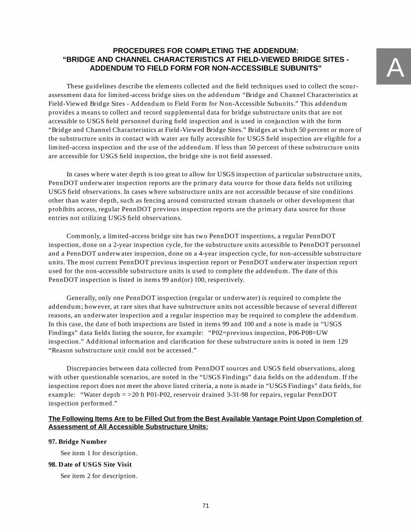
A
71
PROCEDURES FOR COMPLETING THE ADDENDUM:“BRIDGE AND CHANNEL CHARACTERISTICS AT FIELD-VIEWED BRIDGE SITES -
ADDENDUM TO FIELD FORM FOR NON-ACCESSIBLE SUBUNITS”
These guidelines describe the elements collected and the field techniques used to collect the scour-assessment data for limited-access bridge sites on the addendum “Bridge and Channel Characteristics atField-Viewed Bridge Sites - Addendum to Field Form for Non-Accessible Subunits.” This addendumprovides a means to collect and record supplemental data for bridge substructure units that are notaccessible to USGS field personnel during field inspection and is used in conjunction with the form“Bridge and Channel Characteristics at Field-Viewed Bridge Sites.” Bridges at which 50 percent or more ofthe substructure units in contact with water are fully accessible for USGS field inspection are eligible for alimited-access inspection and the use of the addendum. If less than 50 percent of these substructure unitsare accessible for USGS field inspection, the bridge site is not field assessed.
In cases where water depth is too great to allow for USGS inspection of particular substructure units,PennDOT underwater inspection reports are the primary data source for those data fields not utilizingUSGS field observations. In cases where substructure units are not accessible because of site conditionsother than water depth, such as fencing around constructed stream channels or other development thatprohibits access, regular PennDOT previous inspection reports are the primary data source for thoseentries not utilizing USGS field observations.
Commonly, a limited-access bridge site has two PennDOT inspections, a regular PennDOTinspection, done on a 2-year inspection cycle, for the substructure units accessible to PennDOT personneland a PennDOT underwater inspection, done on a 4-year inspection cycle, for non-accessible substructureunits. The most current PennDOT previous inspection report or PennDOT underwater inspection reportused for the non-accessible substructure units is used to complete the addendum. The date of thisPennDOT inspection is listed in items 99 and(or) 100, respectively.
Generally, only one PennDOT inspection (regular or underwater) is required to complete theaddendum; however, at rare sites that have substructure units not accessible because of several differentreasons, an underwater inspection and a regular inspection may be required to complete the addendum.In this case, the date of both inspections are listed in items 99 and 100 and a note is made in “USGSFindings” data fields listing the source, for example: “P02=previous inspection, P06-P08=UWinspection.” Additional information and clarification for these substructure units is noted in item 129“Reason substructure unit could not be accessed.”
Discrepancies between data collected from PennDOT sources and USGS field observations, alongwith other questionable scenarios, are noted in the “USGS Findings” data fields on the addendum. If theinspection report does not meet the above listed criteria, a note is made in “USGS Findings” data fields, forexample: “Water depth = >20 ft P01-P02, reservoir drained 3-31-98 for repairs, regular PennDOTinspection performed.”
The Follo wing Items Are to be Filled Out from the Best Availab le Vantage Point Upon Completion ofAssessment of All Accessib le Substructure Units:
97. Bridge Number
See item 1 for description.
98. Date of USGS Site Visit
See item 2 for description.

A
72
99. Date of Previous Bridge Inspection
The date is the month, day, and year of the PennDOT previous bridge inspection and contains sixdigits that are subset into three two-digit fields (e.g., May 15, 1999 is entered as 051599).
100. Date of Previous Underwater Inspection
The date is the month, day, and year of the PennDOT previous underwater inspection and contains sixdigits that are subset into three two-digit fields (e.g., May 15, 1999 is entered as 051599).
101. Complete Cross Section Surveyed
Yes (1) is entered if a complete cross section is surveyed as detailed in Appendix B. No (0) is entered ifthe survey of a cross section is not possible and an abbreviated survey is completed.
102. Identification of Specific Piers (PennDOT item W09)
See item 40 for description.Primary data source is USGS field observation.
103. Location of Specific Piers
See item 41 for description.Primary data source is USGS field observation.
104. Pier Nose Shape(s)
See item 42 for description.Primary data source is USGS field observation.
105. Pier Type (PennDOT item C39M)
See item 43 for description.Primary data source is USGS field observation.
106. Foundation Type (PennDOT item W10M)
This item indicates the foundation type at specific piers. Entries for this item are 1 = footing onbedrock, 2 = footing on alluvium, 3 = piles/caissons, 4 = other, or 5 = not observed.
Primary data source is USGS field observation.In cases where USGS field observation is inconclusive, an entry of “not observed” is entered.
107. Water Depth (Maximum) (PennDOT item W11)
See item 45 for description. Entries for this item are transcribed directly from PennDOT previousbridge inspection data.
Primary data source is PennDOT previous inspection or PennDOT previous underwater inspection.
108. Pier Attack Angle(s)
See item 46 for description. If low flow has significant effect on the pier, it is addressed in the commentfield 114 “USGS Findings.”
Primary data source is USGS field observation.
109. Debris Width Relative to Pier Width
See item 47 for description.Primary data source is USGS field observation.
110. Evidence of Pier Movement
See item 48 for description.
Primary data source is PennDOT previous inspection or PennDOT previous underwater inspection.USGS field observation is secondary source of information; all discrepancies are noted in item 114“USGS Findings.”

A
73
111. Scour Conditions at Piers
See item 49 for description.
Primary data source is PennDOT previous inspection or PennDOT previous underwater inspection.USGS field observation is secondary source of information; all discrepancies are noted in item 114“USGS Findings.”
112. Scour Depths (PennDOT item W11-C)
See item 62 for description.
Primary data source is PennDOT previous inspection or PennDOT previous underwater inspection.USGS field observation is secondary source of information; all discrepancies are noted in item 114“USGS Findings.”
113. Pier Findings (PennDOT item W12)
This is a narrative description of inspection findings at a specific pier. A W09 entry is used to indicatethe pier being discussed.
Data for this entry is transcribed directly from PennDOT previous bridge inspection data or PennDOTunderwater inspection data.
114. USGS Findings
This is a narrative description of any discrepancies noted between PennDOT information and USGSfield observation along with questionable characteristics and data sources as relating to non-accessiblepiers as listed on the addendum.
115. Abutment Bank Location
See item 53 for description.Primary data source is USGS field observation.
116. Abutment Location
See item 54 for description.Primary data source is USGS field observation.
117. Abutment Type (PennDOT item C37M)
See item 55 for description.Primary data source is USGS field observation.
118. Foundation Type (PennDOT item W10M)
This item indicates the foundation type at each abutment. Entries for this item are 1 = footing onbedrock, 2 = footing on alluvium, 3 = piles/caissons, 4 = other, or 5 = not observed.
Primary data source is USGS field observation.
In cases where USGS field observation is inconclusive, the entry is “not observed.”
119. Water Depth (Maximum) (PennDOT item W11)
See item 57 for description.
Primary data source is PennDOT previous inspection or PennDOT previous underwater inspection.
120. Type of Bridge Opening
See item 58 for description.Primary data source is USGS field observation.
121. Abutment Attack Angle
See item 59 for description. If low flow has significant effect on the abutments, it is addressed in thecomment field 126 “USGS Findings.”
Primary data source is USGS field observation.

A
74
122. Evidence of Abutment Movement
See item 60 for description.
Primary data source for this item is PennDOT previous inspection data and(or) PennDOT underwaterinspection data. USGS field observation is secondary source of information. All discrepancies betweenPennDOT data and USGS field observations are noted in item 126 “USGS Findings.”
123. Scour Conditions at Abutments
See item 61 for description.
Primary data source is PennDOT previous bridge inspection data or PennDOT underwater inspectiondata. USGS field observation is secondary source of information; all discrepancies are noted in item126 “USGS Findings.”
124. Scour Depths (PennDOT item W11-C)
See item 62 for description.
Primary data source is PennDOT previous inspection or PennDOT previous underwater inspection.USGS field observation is secondary source of information; all discrepancies are noted in item 126“USGS Findings.”
125. Abutment Findings (PennDOT item W12)
This is a narrative description of inspection findings at a specific abutment. A W09 entry is used toindicate the abutment being discussed.
Information for this entry is transcribed directly from PennDOT previous bridge inspection data orPennDOT underwater inspection data.
126. USGS Findings
This is a narrative description of any discrepancies noted between PennDOT information and USGSfield observation along with questionable characteristics and data sources as relating to non-accessibleabutments as listed on the addendum.
127. Streambed Material Near the Bridge Substructure Units
See item 66 for description. The addendum only encompasses substructure units that are notaccessible, data for other accessible substructure units are recorded on the “Bridge and ChannelCharacteristics at Field-Viewed Bridge Sites” form.
Primary information for this data field comes from PennDOT previous bridge inspection data orPennDOT underwater inspection data. USGS field observations confirm these data, all discrepanciesare noted in items 114 and(or) 126 “USGS Findings.”
128A - 128J. PennDOT Observed Scour Rating (PennDOT item W11-A)
The addendum only encompasses W11-A entries for substructure units that are not accessible; data forother accessible substructure units are recorded on the “Bridge and Channel Characteristics at Field-Viewed Bridge Sites” form as described in item 67.
Data for items 128A through 128J for limited-access subunits are transcribed directly from PennDOTprevious bridge inspection data or PennDOT underwater inspection data.
129. Reason Substructure Unit Could Not Be Inspected
This item is intended to give a general idea of why the addendum is needed. One of four multiple-choice data items is selected and entered next to the appropriate substructure unit. Entries are1 = water too deep, 2 = water too swift, 3 = safety concerns, or 4 = no access.
Data for this item comes solely from USGS field observation.

75
B
APPENDIX BTOTAL-STATION SURVEY PROCEDURES AND ATTRIBUTES

B
76
TOTAL-STATION SURVEY PROCEDURES AND ATTRIBUTES
Data elements, unless otherwise specified, are directly logged and temporarily stored in the totalstation. “Left” and “right” are determined while facing downstream. Bridge geometry and cross-sectionelements are collected concurrently. Distances, relative to the bridge, are measured along the streamchannel. Significant features, such as high-water marks, directly observable but beyond 200 ft from thebridge are surveyed. Significant features, without specific attributes, are assigned a generic-point attribute(GENPT) and described with a comment within the total station file. All attributes along with adescription of the usage of that attribute are listed in table 6.
Bridges that have structural components that will not be impacted by flooding and will not beotherwise hydrologically or hydraulically affected as a result of the height of the bridge deck and (or) thelateral extent of the bridge structure receive abbreviated surveys. Abbreviated surveys extend laterally tothe landward side of the first substructure unit on each bank resting entirely in the flood plain or otherwiseout of flow and vertically may exclude all upper bridge components including: parapet, road-gradeprofile, wingwalls, and bottom of beams. Abbreviated surveys include, when safety and conditionspermit; points common to PennDOT plans, such as exposed footing; PennDOT plaques and otherreference marks; and GPS locations.
Bridges at which the survey of a complete cross section is not possible, such as limited-access sites,receive a second type of abbreviated survey. At these bridge sites, only the following data elements arerequired: GPS locations, road-grade profile (unless bridge superstructure will not be hydrologically orhydraulically effected by high flows), edge of water upstream, near the bridge, and downstream, andhigh-water marks when available. Edge of water data elements are required on one bank only for this typeof abbreviated survey because of access limitations.

B
77
Table 6. Total-station survey attributes with descriptions
Bridge site feature Attribute Description
Upstream attributeprefix
This prefix is added to attributes to indicate a position at, or relatively near, theupstream face of the bridge.
US Attribute prefix used to denote a position at, or relatively near, the upstream face ofthe bridge; for example USRWWT (upstream right wingwall top).
Downstream attributeprefix
This prefix may replace upstream (US) in any attribute for which the downstreambridge feature is deemed significant and requires definition. In addition, the DSprefix must be attached to the attributes for the cross section and bottom of beamshots when the cross section is taken at the downstream face of the bridge structure.
DS Attribute prefix used to denote a position at the downstream face of the bridge; forexample DSXS (downstream, cross section).
Cross-section
Surveyed points define the streambed at the most restrictive opening at the bridgesite, taking into account exposed utilities and (or) other permanent obstructions.
XS Attribute defining a break in slope in the channel along the cross section. Thisattribute may also be used as a prefix to other attributes in order to denote a featureas being within the plane of the cross section; for example, XSRA (cross section,right abutment).
Abutment Surveyed points define various locations at the right and (or) left abutments for use indetermining exposed footing elevations and (or) defining bridge geometry. An “R”is used to indicate the right side of the abutment, an “L” to indicate the left side ofthe abutment.
RA or LA Attribute used in conjunction with a suffix to define features of significance at theright or left abutment, for example, RAF (right abutment, exposed footing) orLAPW (left abutment, protective works).
XSRA or XSLA Attribute defining right or left side of cross section at the abutment. A “J” suffix maybe attached to indicate this is also the junction with the streamward bottom of theright or left wingwall if applicable.
USRAT orUSLAT
Attribute used to define the streamward top of the right or left abutment mass.
USRLEAT orUSLLEAT
Attribute used to define the landward top of the right or left abutment mass.
USRLEA orUSLLEA
Attribute used to define the landward bottom of the right or left abutment mass.
Pier Surveyed points define the shape of the pier as it appears in a plot of the cross sectionand elevation of the bridge. The pier number is added to the attribute in numericformat (01, 02, 03, and so forth). Pier number is displayed here as “##.” An “R” isused to indicate the right side of the pier, an “L” to indicate the left side of the pier.
RP## or LP## Attribute used to define the point where the streambed and pier intersect outside ofthe plane of the cross section along the side of the pier. This attribute is used in con-junction with a suffix to define features of significance along the side of a pier, forexample, RP##F (right side of pier ##, exposed footing) or LP##PW (left side of pier##, protective works).
XSRP## orXSLP##
Attribute used to define the point where the streambed and pier intersect in the planeof the cross section on the right or left side of the pier. A suffix may be attached todescribe features of significance at this point, such as exposed footing (XSRP##F),deposition (XSRP##DEP), and so forth.
USNP## Attribute used in conjunction with a suffix to define the nose of pier in cases wheredebris, deposition, or scour holes are at, or around, the pier nose (for example,USNP##DP, or USNP##DEP). Attribute used also in cases where pier nose requiresdefinition due to pier location outside of the plane of the cross section.
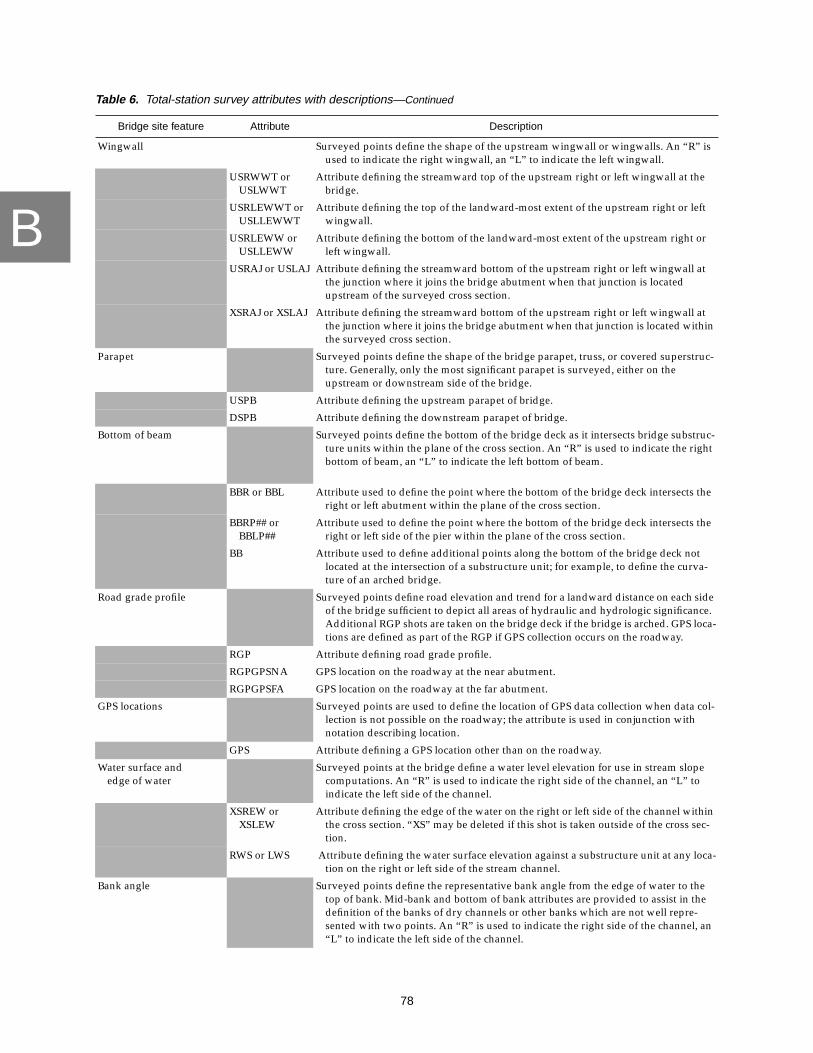
B
78
Wingwall Surveyed points define the shape of the upstream wingwall or wingwalls. An “R” isused to indicate the right wingwall, an “L” to indicate the left wingwall.
USRWWT orUSLWWT
Attribute defining the streamward top of the upstream right or left wingwall at thebridge.
USRLEWWT orUSLLEWWT
Attribute defining the top of the landward-most extent of the upstream right or leftwingwall.
USRLEWW orUSLLEWW
Attribute defining the bottom of the landward-most extent of the upstream right orleft wingwall.
USRAJ or USLAJ Attribute defining the streamward bottom of the upstream right or left wingwall atthe junction where it joins the bridge abutment when that junction is locatedupstream of the surveyed cross section.
XSRAJ or XSLAJ Attribute defining the streamward bottom of the upstream right or left wingwall atthe junction where it joins the bridge abutment when that junction is located withinthe surveyed cross section.
Parapet Surveyed points define the shape of the bridge parapet, truss, or covered superstruc-ture. Generally, only the most significant parapet is surveyed, either on theupstream or downstream side of the bridge.
USPB Attribute defining the upstream parapet of bridge.
DSPB Attribute defining the downstream parapet of bridge.
Bottom of beam Surveyed points define the bottom of the bridge deck as it intersects bridge substruc-ture units within the plane of the cross section. An “R” is used to indicate the rightbottom of beam, an “L” to indicate the left bottom of beam.
BBR or BBL Attribute used to define the point where the bottom of the bridge deck intersects theright or left abutment within the plane of the cross section.
BBRP## orBBLP##
Attribute used to define the point where the bottom of the bridge deck intersects theright or left side of the pier within the plane of the cross section.
BB Attribute used to define additional points along the bottom of the bridge deck notlocated at the intersection of a substructure unit; for example, to define the curva-ture of an arched bridge.
Road grade profile Surveyed points define road elevation and trend for a landward distance on each sideof the bridge sufficient to depict all areas of hydraulic and hydrologic significance.Additional RGP shots are taken on the bridge deck if the bridge is arched. GPS loca-tions are defined as part of the RGP if GPS collection occurs on the roadway.
RGP Attribute defining road grade profile.
RGPGPSNA GPS location on the roadway at the near abutment.
RGPGPSFA GPS location on the roadway at the far abutment.
GPS locations Surveyed points are used to define the location of GPS data collection when data col-lection is not possible on the roadway; the attribute is used in conjunction withnotation describing location.
GPS Attribute defining a GPS location other than on the roadway.
Water surface andedge of water
Surveyed points at the bridge define a water level elevation for use in stream slopecomputations. An “R” is used to indicate the right side of the channel, an “L” toindicate the left side of the channel.
XSREW orXSLEW
Attribute defining the edge of the water on the right or left side of the channel withinthe cross section. “XS” may be deleted if this shot is taken outside of the cross sec-tion.
RWS or LWS Attribute defining the water surface elevation against a substructure unit at any loca-tion on the right or left side of the stream channel.
Bank angle Surveyed points define the representative bank angle from the edge of water to thetop of bank. Mid-bank and bottom of bank attributes are provided to assist in thedefinition of the banks of dry channels or other banks which are not well repre-sented with two points. An “R” is used to indicate the right side of the channel, an“L” to indicate the left side of the channel.
Table 6. Total-station survey attributes with descriptions—Continued
Bridge site feature Attribute Description

B
79
USRTB orUSLTB
Attribute used to define the upstream right or left top of bank.
USREW orUSLEW
Attribute used to define the upstream right or left edge of water.
USRMB orUSLMB
Attribute used to define various breaks in slope in mid-bank locations between theupstream right or left bottom of bank and the upstream right or left top of banklocations.
USRBOB orUSLBOB
Attribute used to define the upstream right or left bottom of bank.
DSRTB orDSLTB
Attribute used to define the downstream right or left top of bank.
DSREW orDSLEW
Attribute used to define the downstream right or left edge of water.
DSRMB orDSLMB
Attribute used to define various breaks in slope in mid-bank locations between thedownstream right or left bottom of bank and the downstream right or left top ofbank locations.
DSRBOB orDSLBOB
Attribute used to define the downstream right or left bottom of bank.
Debris piles Surveyed points define significant debris piles at any location throughout the bridgesite.
DP Attribute used in conjunction with other attributes to denote the presence of debris;for example, XSDP (cross section, debris pile)
DPUS Attribute used to define the farthest upstream extent of the debris pile.
DPRS Attribute used to define the farthest right extent of the debris pile.
DPLS Attribute used to define the farthest left extent of the debris pile.
DPDS Attribute used to define the farthest downstream extent of the debris pile.
DPT Attribute used to define the greatest elevation (top) of the debris pile.
Deposition Surveyed points define significant areas of deposition at any location throughout thebridge site.
DEP Attribute used in conjunction with other attributes to denote the presence of a signifi-cant depositional feature; for example, XSDEP (cross section, deposition)
DEPUS Attribute used to define the farthest upstream extent of the area of deposition.
DEPRS Attribute used to define the farthest right extent of the area of deposition.
DEPLS Attribute used to define the farthest left extent of the area of deposition.
DEPDS Attribute used to define the farthest downstream extent of the area of deposition.
DEPT Attribute used to define the greatest elevation (top) of the area of deposition.
Scour Hole Surveyed points define significant scour holes at any location throughout the bridgesite.
SH Attribute used in conjunction with other attributes to denote the presence of a signifi-cant scour hole; for example, SH01US (scour hole, number 01, upstream end)
SH##US Attribute used to define the farthest upstream extent of the scour hole.
SH##RS Attribute used to define the farthest right extent of the scour hole.
SH##LS Attribute used to define the farthest left extent of the scour hole.
SH##DS Attribute used to define the farthest downstream extent of the scour hole.
SH##B Attribute used to define the lowest elevation (bottom) of the scour hole.
Bench marks, monuments,and reference points
These features are surveyed when located at, or in the immediate vicinity, of thebridge.
PDOTPLAK Attribute used for all established monuments including, but not limited to, USGSbenchmarks, Coast and Geodetic Survey (CGS) monuments, and PennDOT, county,or township plaques.
PK Attribute used to define the location of the USGS-installed PK masonry nail.
Table 6. Total-station survey attributes with descriptions—Continued
Bridge site feature Attribute Description

B
80
RM Attribute used to define previously existing survey marks such as, old chiseledsquares, old PK masonry nails, and so forth.
Exposed Footing Surveyed points define exposed footing on abutments, piers, and wingwalls. Footingattributes are used in conjunction with other attributes which describe the locationof the exposed footing; for example, RAF (right abutment, footing).
F Attribute suffix used to define the top of the exposed footing as it abuts the bridgesubstructure unit.
FC Attribute suffix used to define an edge, or corner, on exposed footing.
FS Attribute suffix used to define the point of intersection between the footing and thestreambed.
Protective work Surveyed points define protective works on or around abutments, piers, wingwalls,stream banks and channel. Protective work attributes are used in conjunction withother attributes which describe the location of the protective work; for example,XSRR (cross section, riprap).
RR Attribute suffix indicating the presence of riprap.
PW Attribute suffix used to define the top of a protective work as it abuts the bridge sub-structure unit.
PWC Attribute suffix used to define an edge, or corner, on a protective work.
PWS Attribute suffix used to define the point of intersection between the protective workand the streambed.
Unknown points Those points that are not addressed by standard attributes must be assigned a genericpoint with notation describing the location of the surveyed point.
GENPT Attribute used for non-standard surveyed points. Requires the input of notationdescribing the location of the surveyed point.
Table 6. Total-station survey attributes with descriptions—Continued
Bridge site feature Attribute Description

81
CAPPENDIX C
LOCATION AND IDENTIFICATION OF GLOBAL POSITIONING
SYSTEM BASE STATIONS USED IN PENNSYLVANIA

C
82
GPS base stations are located throughout Pennsylvania and adjacent states. Data from the nearestbase station (fig. 26) is used to correct GPS data collected at bridge sites throughout Pennsylvania.Base stations are independently operated and no guarantee is made that data will be available from anyspecific base station for the times required; therefore, a primary and alternate base station are assigned toeach county in Pennsylvania as given in table 7. In the event that the primary base station is notoperational, data from the alternate base station is downloaded to a computer directory and used tocorrect GPS data. Each base station establishes unique procedures for acquisition of data from that site;these procedures are generally available on the internet.
Figure 26. Location of global positioning system base stations.

C
83
Table 7. Primary and secondary global positioning system base stations for each countyin Pennsylvania
County nameCountynumber
PennDOTdistrict
Primary base station Secondary base station
Adams 1 8 Gaithersburg, Md. Penn StateAllegheny 2 11 Allegheny Nat. Forest Morgantown, W.Va.Armstrong 3 10 Allegheny Nat. Forest Penn StateBeaver 4 11 Allegheny Nat. Forest Morgantown, W.Va.Bedford 5 9 Penn State Morgantown, W.Va.Berks 6 5 Trenton, N.J. Wilkes-Barre, Pa.Blair 7 9 Penn State Morgantown, W.Va.Bradford 8 3 Wilkes-Barre, Pa. Penn StateBucks 9 6 Trenton, N.J. Edison, N.J.Butler 10 10 Allegheny Nat. Forest Morgantown, W.Va.Cambria 11 9 Penn State Morgantown, W.Va.Cameron 12 2 Penn State Allegheny Nat. ForestCarbon 13 5 Wilkes-Barre, Pa. Trenton, N.J.Centre 14 2 Penn State Wilkes-Barre, Pa.Chester 15 6 Trenton, N.J. Gaithersburg, Md.Clarion 16 10 Allegheny Nat. Forest Penn StateClearfield 17 2 Penn State Allegheny Nat. ForestClinton 18 2 Penn State Wilkes-Barre, Pa.Columbia 19 3 Wilkes-Barre, Pa. Penn StateCrawford 20 1 Allegheny Nat. Forest Penn StateCumberland 21 8 Penn State Gaithersburg, Md.Dauphin 22 8 Penn State Gaithersburg, Md.Delaware 23 6 Trenton, N.J. Gaithersburg, Md.Elk 24 2 Allegheny Nat. Forest Penn StateErie 25 1 Allegheny Nat. Forest Penn StateFayette 26 12 Penn State Morgantown, W.Va.Forest 27 1 Allegheny Nat. Forest Penn StateFranklin 28 8 Penn State Gaithersburg, Md.Fulton 29 9 Penn State Gaithersburg, Md.Greene 30 12 Penn State Morgantown, W.Va.Huntingdon 31 9 Penn State Gaithersburg, Md.Indiana 32 10 Penn State Allegheny Nat. ForestJefferson 33 10 Allegheny Nat. Forest Penn StateJuniata 34 2 Penn State Wilkes-Barre, Pa.Lackawanna 35 4 Wilkes-Barre, Pa. Edison, N.J.Lancaster 36 8 Trenton, N.J. Penn StateLawrence 37 11 Allegheny Nat. Forest Morgantown, W.Va.Lebanon 38 8 Penn State Wilkes-Barre, Pa.Lehigh 39 5 Trenton, N.J. Wilkes-Barre, Pa.Luzerne 40 4 Wilkes-Barre, Pa. Penn StateLycoming 41 3 Wilkes-Barre, Pa. Penn StateMcKean 42 2 Allegheny Nat. Forest Penn StateMercer 43 1 Allegheny Nat. Forest Morgantown, W.Va.Mifflin 44 2 Penn State Wilkes-Barre, Pa.Monroe 45 5 Wilkes-Barre, Pa. Edison, N.J.Montgomery 46 6 Trenton, N.J. Edison, N.J.Montour 47 3 Wilkes-Barre, Pa. Penn StateNorthampton 48 5 Trenton, N.J. Wilkes-Barre Pa.Northumberland 49 3 Wilkes-Barre, Pa. Penn State

C
84
Perry 50 8 Penn State Wilkes-Barre, Pa.Pike 51 4 Wilkes-Barre, Pa. Edison, N.J.Potter 52 2 Penn State Allegheny Nat. ForestSchuylkill 53 5 Wilkes-Barre, Pa. Penn StateSnyder 54 3 Penn State Wilkes-Barre, Pa.Somerset 55 9 Penn State Morgantown, W.Va.Sullivan 56 3 Wilkes-Barre, Pa. Penn StateSusquehanna 57 4 Wilkes-Barre, Pa. Edison, N.J.Tioga 58 3 Wilkes-Barre, Pa. Penn StateUnion 59 3 Penn State Wilkes-Barre, Pa.Venango 60 1 Allegheny Nat. Forest Penn StateWarren 61 1 Allegheny Nat. Forest Penn StateWashington 62 12 Penn State Morgantown, W.Va.Wayne 63 4 Wilkes-Barre, Pa. Edison, N.J.Westmoreland 64 12 Penn State Morgantown, W.Va.Wyoming 65 4 Wilkes-Barre, Pa. Edison, N.J.York 66 8 Penn State Gaithersburg, Md.Philadelphia 67 6 Trenton, N.J. Edison, N.J.
Table 7. Primary and secondary global positioning system base stations for each countyin Pennsylvania—Continued
County nameCountynumber
PennDOTdistrict
Primary base station Secondary base station

85
DAPPENDIX DPROCEDURE FOR COLLECTION OF VIDEO-TAPE DATA

D
86
PROCEDURE FOR COLLECTION OF VIDEO-TAPE DATA
Video-tape data is collected from several locations at each field-viewed bridge site to provide avisual record of site conditions on the day of the assessment. Field personnel pan slowly and smoothlyusing survey rods or other points of reference to provide a relative scale to the viewer. The images must beclearly visible in the viewfinder to insure acceptable visibility on the tape with at least a 5 second pause onany image that is to be captured. Video-tape data of the bridge site includes narration by field personnel toprovide a concise, detailed description of significant site characteristics.
Collecting Video-tape Data fr om the Bridg e Looking Upstream and Do wnstream
Standing on the upstream side of the bridge deck or at an equivalent location, video-tape data withnarration is collected to document the channel conditions and significant features (e.g. meander impacts,cut banks, and mid-channel and point bars) within two bridge lengths upstream from the bridge.The videographer begins with a view of the near roadway approach and completes a slow pan of theupstream reach ending with a view of the far roadway approach. The pan subsequently continues fromthe view of the far roadway approach down along the face of the bridge, showing significant features suchas debris accumulation at the face of the bridge and(or) deposition, and continues back to a view of thenear roadway approach. When possible, the foreground of this video includes some point of reference,such as a survey rod, that gives a sense of depth and perspective to the picture. The videographer alsonotes in the narration where the video was taken (on, under, or near the bridge). This process is repeated atthe downstream face of the bridge viewing the downstream reach of the stream.
Collecting Video-tape Data fr om the Upstream and Do wnstream Channel
Standing in the upstream channel or in an equivalent location, video-tape data is collectedillustrating the channel conditions within the upstream reach. The videographer begins by lookingupstream and completes a slow 360 degree pan down stream bank toward the near abutment. As the panpasses across the bridge opening, the videographer pauses a minimum of 5 seconds with the upstreamface of bridge completely framed. This pause enables the image to be captured by commercially availablecomputer software. The pan subsequently continues from the view of the bridge face, up the oppositebank, and ends on the view looking upstream. Narration typically includes location of the videographer,comments on any erosional features, relative distances, streambed material, and any other significantcharacteristics of the upstream reach. When possible, the foreground of this video includes some point ofreference, such as a survey rod, that gives a sense of depth and perspective to the picture. The video-grapher stands only as far from the bridge as is necessary to frame the entire bridge opening andwingwalls in the viewfinder. Every effort is made to frame as much of the complete bridge opening aspossible and to attempt to provide a clear view through the bridge opening. If standing in the stream doesnot provide an acceptable view of the bridge opening, a different vantage point is selected to collect video-tape data. An oblique view of the bridge face is provided if a clear view through the bridge opening cannotbe provided because of vegetation or other factors. This process is repeated in the downstream channel.
Additional Video
Additional video is taken of any item that indicates a site has a significant stability problem, forexample, sediment or debris blockage, failed countermeasures, significant erosion or movement, or anyitem that results in a designation of “PHONE” bridge. Additional video-tape data is collected only if thefeature to be video-taped is significant and clearly visible.

87
E
APPENDIX EFORM AND PROCEDURES FOR COMPLETION OF THE
“B RIDGE AND CHANNEL CHARACTERISTICS AT
OFFICE-REVIEWED BRIDGE SITES” F ORM

E
88
Figure 27. “Bridge and Channel Characteristics at Office-Reviewed Bridge Sites” form.

E
89
Figure 27. “Bridge and Channel Characteristics at Office-Reviewed Bridge Sites” form—Continued.

E
90
Figure 27. “Bridge and Channel Characteristics at Office-Reviewed Bridge Sites” form—Continued.

E
91
Figure 27. “Bridge and Channel Characteristics at Office-Reviewed Bridge Sites” form—Continued.

E
92
Figure 27. “Bridge and Channel Characteristics at Office-Reviewed Bridge Sites” form—Continued.

E
93
Figure 27. “Bridge and Channel Characteristics at Office-Reviewed Bridge Sites” form—Continued.

E
94
Figure 27. “Bridge and Channel Characteristics at Office-Reviewed Bridge Sites” form—Continued.

E
95
Figure 27. “Bridge and Channel Characteristics at Office-Reviewed Bridge Sites” form—Continued.
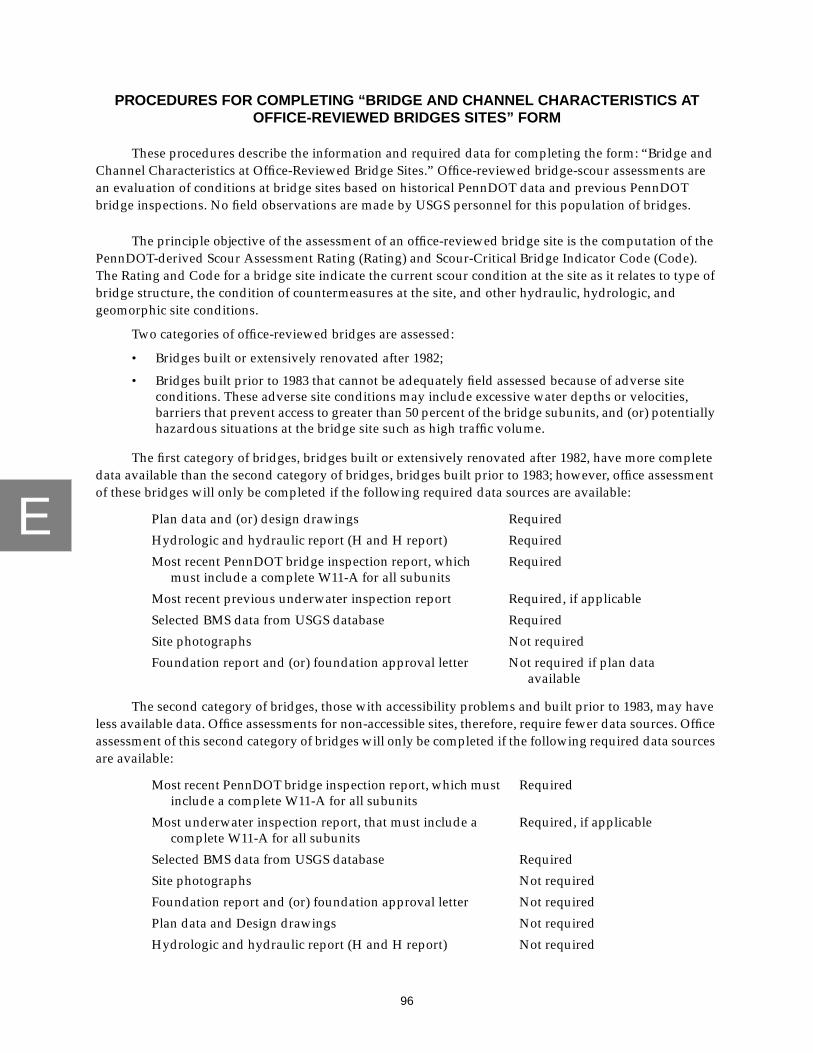
E
96
PROCEDURES FOR COMPLETING “BRIDGE AND CHANNEL CHARACTERISTICS ATOFFICE-REVIEWED BRIDGES SITES” FORM
These procedures describe the information and required data for completing the form: “Bridge andChannel Characteristics at Office-Reviewed Bridge Sites.” Office-reviewed bridge-scour assessments arean evaluation of conditions at bridge sites based on historical PennDOT data and previous PennDOTbridge inspections. No field observations are made by USGS personnel for this population of bridges.
The principle objective of the assessment of an office-reviewed bridge site is the computation of thePennDOT-derived Scour Assessment Rating (Rating) and Scour-Critical Bridge Indicator Code (Code).The Rating and Code for a bridge site indicate the current scour condition at the site as it relates to type ofbridge structure, the condition of countermeasures at the site, and other hydraulic, hydrologic, andgeomorphic site conditions.
Two categories of office-reviewed bridges are assessed:
• Bridges built or extensively renovated after 1982;
• Bridges built prior to 1983 that cannot be adequately field assessed because of adverse siteconditions. These adverse site conditions may include excessive water depths or velocities,barriers that prevent access to greater than 50 percent of the bridge subunits, and (or) potentiallyhazardous situations at the bridge site such as high traffic volume.
The first category of bridges, bridges built or extensively renovated after 1982, have more completedata available than the second category of bridges, bridges built prior to 1983; however, office assessmentof these bridges will only be completed if the following required data sources are available:
The second category of bridges, those with accessibility problems and built prior to 1983, may haveless available data. Office assessments for non-accessible sites, therefore, require fewer data sources. Officeassessment of this second category of bridges will only be completed if the following required data sourcesare available:
Plan data and (or) design drawings Required
Hydrologic and hydraulic report (H and H report) Required
Most recent PennDOT bridge inspection report, whichmust include a complete W11-A for all subunits
Required
Most recent previous underwater inspection report Required, if applicable
Selected BMS data from USGS database Required
Site photographs Not required
Foundation report and (or) foundation approval letter Not required if plan dataavailable
Most recent PennDOT bridge inspection report, which mustinclude a complete W11-A for all subunits
Required
Most underwater inspection report, that must include acomplete W11-A for all subunits
Required, if applicable
Selected BMS data from USGS database Required
Site photographs Not required
Foundation report and (or) foundation approval letter Not required
Plan data and Design drawings Not required
Hydrologic and hydraulic report (H and H report) Not required

E
97
Other data sources and the associated dates of these data sources are documented in a suppliedcomment field if they are used for the assessment of a bridge site. If data is not available to complete anoffice assessment, the bridge site will be visited and scour assessment completed by PennDOT personnel.
Data fields required for computation of the Rating and Code are starred (*) on the data-collectionform and in the procedures guide to ensure that these fields are completed. When required, USGSpersonnel work with PennDOT District personnel to compile the data to complete these fields. No office-reviewed bridge assessment is complete unless all starred fields are complete, therefore, a qualitativeinterpretation of existing PennDOT data is commonly necessary to complete office-reviewed bridgeassessments.
Boxed items on the assessment form indicate fields for which data will frequently be unavailable.An entry is 99 = CNBD (cannot be determined) in any boxed data field for which there is not a high degreeof certainty. The 99 = CNBD entry cannot be used in starred data fields.
USGS personnel assume the PennDOT data sources adequately and completely document a bridgesite for the assessment of scour and channel stability. If the previous PennDOT inspection makes norecommendations for maintenance or improvements, the assessor assumes no condition exists at the sitethat indicates concern or problems. If assessors find inconsistencies among the PennDOT data sources,PennDOT District personnel are contacted to resolve these conflicts during the time at which USGSpersonnel are completing the assessments (Bryan J. Spangler P.E., Pennsylvania Department ofTransportation, oral commun., 1998).
*1. Assessed Bridge Number
The assessed bridge number is the structure identification according to item A01 of BMS Pub 100A(Pennsylvania Department of Transportation, 1993) on the day of the site assessment.
Data Source(s):
BMS data
2. Name of Assessor
This item records the name of USGS personnel conducting the office assessment, and consist of thefirst and middle initials and the last name
3. Date of Office Assessment
This item records the date of the USGS office assessment by month, day, and year.
*4. Year Built
This item records the year the bridge was built.
Data Source(s):
BMS dataPennDOT personnel

E
98
5. Information Available For This Assessment
The assessor records the type and dates of the available PennDOT information in the provided blanks.The entry is 99 = CNBD if the information is unavailable. Caution must be taken, because data forprevious bridge structures located at a particular site and data for the current bridge structure may bepresent in the same file. Assessors must ensure that the data compiled is for the current bridge at thesite. If a required data source, as listed above, is not available, the office assessment cannot becompleted.
Multiple dates may be available for PennDOT inspection reports. In these cases, the date that the mostrecent PennDOT inspection was completed by PennDOT personnel is recorded and not the date thedata was entered into the PennDOT database and was approved for use. Photographs may spanmultiple years and are not updated until a change at the site warrants replacement with a morecurrent photograph; therefore, the dates of all available photographs are entered in the spacesprovided. Additional sources used are noted in the comment field.
6. Reason for Office Assessment
This item records the reason an office review is completed instead of viewing the site in the field.The entries are 1 = Bridge built or extensively renovated after 1982, or 2 = Bridge built prior to 1983with site-access problems.
7. Surface Cover
This item records the surface cover in the vicinity of the bridge. Surface cover for the upstream leftoverbank (USLOB), upstream right overbank (USROB), downstream left overbank (DSLOB), anddownstream right overbank (DSROB) are described for a distance of two bridge-lengths or 200 ftupstream and downstream from the bridge and up to two bridge-lengths or 200 ft landward from thestream. The category that best describes the overall ground cover of the bridge site is recorded also.Entries are 1 = >50% paved; 2 = 10%-50% paved; 3 = row crop; 4 = pasture; 5 = brush; 6 = forest;7 = wetland; 8 = structure; or 99 = CNBD (cannot be determined)
Data Source(s)
PhotographsSite data section of H and H report
8. Angle of Approach
This item records the angle of approach in degrees. The angle of approach is a comparison of theupstream and downstream reaches and is determined using the low-flow channel boundaries as theyappear in the site plan and not the banklines as used for field-viewed bridge assessments. The assessordetermines the direction from which flow approaches the bridge and the direction along which flowexits the bridge, taking into consideration the entire reach so that sinuous thalwegs do not effect theresult. Entries are 1 = 0 to 5 degrees; 2 = 6 to 15 degrees; 3 = 16 to 30 degrees; 4 = 31 to 45 degrees; 5 = 46to 90; or 99 = CNBD (cannot be determined). Flow paths directed toward the left bank are recordedwith the angle category preceded by a minus (-) sign. Flow paths directed toward the right bank arerecorded with the angle category and the positive (+) sign is assumed.
Data Source(s)
Site plan in H and H reportSite location mapsPlan data
9. Angle of Skew
This item records the angle of flow relative to the upstream face of the bridge. The angle of skew isdetermined by use of the low-flow channel boundaries as they appear in the site plan and not thebanklines as used for field-viewed bridge assessments. Entries are 1 = 90 to 85 degrees; 2 = 84 to
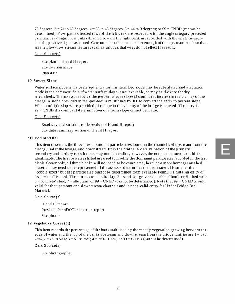
E
99
75 degrees; 3 = 74 to 60 degrees; 4 = 59 to 45 degrees; 5 = 44 to 0 degrees; or 99 = CNBD (cannot bedetermined). Flow paths directed toward the left bank are recorded with the angle category precededby a minus (-) sign. Flow paths directed toward the right bank are recorded with the angle categoryand the positive sign is assumed. Care must be taken to consider enough of the upstream reach so thatsmaller, low-flow stream features such as sinuous thalwegs do not effect the result.
Data Source(s)
Site plan in H and H reportSite location mapsPlan data
10. Stream Slope
Water surface slope is the preferred entry for this item. Bed slope may be substituted and a notationmade in the comment field if water surface slope is not available, as may be the case for drystreambeds. The assessor records the percent stream slope (3 significant figures) in the vicinity of thebridge. A slope provided in feet-per-foot is multiplied by 100 to convert the entry to percent slope.When multiple slopes are provided, the slope in the vicinity of the bridge is entered. The entry is99 = CNBD if a confident determination of stream slope cannot be made.
Data Source(s)
Roadway and stream profile section of H and H reportSite data summary section of H and H report
*11. Bed Material
This item describes the three most abundant particle sizes found in the channel bed upstream from thebridge, under the bridge, and downstream from the bridge. A determination of the primary,secondary and tertiary constituents may not be possible, however, the main constituent should beidentifiable. The first two sizes listed are used to modify the dominant particle size recorded in the lastblank. Commonly, all three blanks will not need to be completed, because a more homogenous bedmaterial may need to be represented. If the assessor determines the bed material is smaller than“cobble sized” but the particle size cannot be determined from available PennDOT data, an entry of“Alluvium” is used. The entries are 1 = silt/clay; 2 = sand; 3 = gravel; 4 = cobble/boulder; 5 = bedrock;6 = concrete/steel; 7 = alluvium; or 99 = CNBD (cannot be determined). Note that 99 = CNBD is onlyvalid for the upstream and downstream channels and is not a valid entry for Under Bridge BedMaterial.
Data Source(s)
H and H reportPrevious PennDOT inspection reportSite photos
12. Vegetative Cover (%)
This item records the percentage of the bank stabilized by the woody vegetation growing between theedge of water and the top of the banks upstream and downstream from the bridge. Entries are 1 = 0 to25%; 2 = 26 to 50%; 3 = 51 to 75%; 4 = 76 to 100%; or 99 = CNBD (cannot be determined).
Data Source(s)
Site photographs

E
100
13. Tributary
This item records the existence and bank location of significant tributaries within two bridge lengthsor 200 ft upstream from the bridge, under the bridge, or within two bridge lengths or 200 ftdownstream from the bridge. Culvert pipes with a diameter of 3 ft or greater are consideredtributaries. Entries are 0 = No, tributary is not present; 1 = Yes, tributary is present; or 99 = CNBD(cannot be determined). Significant aspects of the tributary are addressed in the comment field.
Data Source(s)
Site photographsSite plan in H and H report
14. Bank Erosion
This item indicates whether or not there is evidence of bank erosion in the upstream channel, underthe bridge, or in the downstream channel; and, if possible, the degree to which that bank erosion isimpacting the site. The entries are 0 = no evidence of erosion (bedrock present); 1 = no evidence oferosion; 2 = evidence of minor erosion; 3 = evidence of significant erosion; or 99 = CNBD (cannot bedetermined). More specific information describing the extent of the erosion at the bridge site is notedin the comment field provided.
Data Source(s)
Site photographsSite data section of H and H reportEmbankment erosion section of H and H report
15. Roadway Approach Impacted
This item records the presence and location of potential impacts on roadways resulting from channelmigration or instability near the bridge. Entries are 1 = near, the near roadway approach is impacted;2 = far, the far roadway approach is impacted; 3 = adjacent, an adjacent roadway (not carried by thebridge) is impacted; or 4 = no, roadways are not impacted. If a roadway is impacted, the assessorcomments on any significant characteristics documented in the PennDOT data sources that lead to thisconclusion. No mention of a specific roadway impact is assumed to be an indication that none exists.
Data Source(s)
Approach roadway condition rating (E15) of previous PennDOT inspection reportSite photosSite plan in H and H report
16. Meander Impact
This item records the presence and bank location of impacts upon the channel banks caused by ameandering channel within two bridge lengths or 200 ft upstream from the bridge, under the bridge,and within two bridge lengths or 200 ft downstream from the bridge. The entries are 0 = no, meanderimpact is not present; 1 = yes, meander impact is present; or 99 = CNBD (cannot be determined),presence or absence of a meander impact cannot be confidently determined.
Data Source(s)
Site plan in H and H reportSite photographsEmbankment erosion section of previous PennDOT inspection report

E
101
17. Cutbank
This item records the presence and bank location of cutbanks within two bridge lengths or 200 ftupstream, under the bridge, and within two bridge lengths or 200 ft downstream from the bridge.The entries are 0 = no, cutbank is not present; 1 = yes, cutbank is present; or 99 = CNBD (cannot bedetermined), presence or absence of a cutbank cannot be confidently determined.
Data Source(s)
Embankment erosion section of previous PennDOT inspection reportSite photographsSite data section of H and H report
18. Point Bar
This item records the presence or the absence of significant, lateral accumulations of sedimentupstream from the bridge, under the bridge, and downstream from the bridge. The entries are 0 = no,point bar is not present; 1 = yes, point bar is present; or 99 = CNBD (cannot be determined).
Data Source(s)
Plan dataSite photographs
19. Point Bar Vegetated
This item records the presence or absence of woody vegetation on an existing point bar. The entries are0 = no, point bar vegetation is not present; 1 = yes, point bar vegetation is present; or 99 = CNBD(cannot be determined).
Data Source(s)
Site photographs
20. Mid-Channel Bar
This item records the presence or absence of significant accumulations of sediment in mid-channellocations upstream from the bridge, under the bridge, and downstream from the bridge. The entriesare 0 = no, mid-channel bar is not present; 1 = yes, mid-channel bar is present; or 99 = CNBD (cannotbe determined).
Data Source(s)
Plan dataSite photographs
21. Mid-Channel Bar Vegetated
This item records the presence or absence of woody vegetation on an existing mid-channel bar. Theentries are 0 = no, mid-channel bar vegetation is not present; 1 = yes, mid-channel bar vegetation ispresent; or 99 = CNBD (cannot be determined).
Data Source(s)
Site photographs
22. Upstream Countermeasures
This item records the presence or absence of countermeasures within two bridge lengths or 200 ftupstream from the bridge. If no countermeasures are in place, the entry is 0 = none under the heading“Type.” If countermeasures are in place, the type, location, and condition of the countermeasure(s) isindicated. The entries for “Type” are 0 = none; 1 = riprap; 2 = gabions; 3 = guidebanks or 4 = other.

E
102
An entry of “other” is explained by a notation in the comment field. If there is no specific evidence fora countermeasure, an entry of 0 or “none” is appropriate. Locations of existing countermeasures arerecorded by selecting from the list of abbreviations that includes: 1 = USLOB, upstream left overbank;2 = USLB, upstream left bank; 3 = US Channel, upstream channel; 4 = USRB, upstream right bank;5 = USROB, upstream right overbank. The entries for the condition of an existing countermeasure are1 = good (countermeasure provides protective barrier to erosive mechanisms at high flow); 2 = partial(countermeasure is insufficient to provide total protective barrier to erosive mechanisms at high flow);or 3 = failed (countermeasure is not providing the protection from erosive processes for which it wasinstalled). The condition of an existing countermeasure is assumed to be good unless specificallynoted as otherwise by the available PennDOT data sources.
Data Source(s)
Plan dataChannel/embankment protection section of previous PennDOT inspection reportMaintenance and major improvement needs section (PennDOT items H01, H03, and
H05) of previous PennDOT inspection reportHydraulic analysis section of H and H report
23. Under Bridge Countermeasures
This item records the presence or absence of countermeasures under the bridge. If no countermeasuresare in place, the entry is 0 = none under the heading “Type.” If countermeasures are in place, the type,location, and condition of the countermeasures are indicated. The entries for “Type” are 0 = none;1 = riprap; 2 = gabions; 3 = guidebanks; 4 = concrete encasement; or 5 = other. An entry of “other” isexplained by a notation in the comment field provided. If there is no specific evidence of acountermeasure, an entry of “none” is appropriate. Locations of existing countermeasures arerecorded by selecting from the list of abbreviations that includes: 1 = USLWW (upstream leftwingwall); 2 = USRWW (upstream right wingwall); 3 = NAB (near abutment); 4 = pier; 5 = channel;6 = FAB (far abutment); 7 = LB (left bank); 8 = RB (right bank); 9 = DSLWW (downstream leftwingwall); 10 = DSRWW (downstream right wingwall). The condition of existing countermeasures arerecorded as described in item 22: 1 = good; 2 = partial; 3 = failed. The condition of an existingcountermeasure is assumed to be good unless specifically described as otherwise by the availablePennDOT data sources.
Data Source(s)
Plan dataChannel/embankment protection section of previous PennDOT inspection reportMaintenance and major improvement needs section (H01, H03, H05) of previous
PennDOT inspection reportHydraulic analysis section of H and H report
24. Downstream Countermeasures
This item is determined as described in item 22, with the exception that described countermeasuresare located within two bridge lengths or 200 ft downstream from the bridge.
Data Source(s)
Plan dataChannel/embankment protection section of previous PennDOT inspection reportMaintenance and major improvement needs section (H01, H03, H05) of previous
PennDOT inspection reportHydraulic analysis section of H and H report

E
103
25. Scour Holes (Not in Contact with Substructure)
This item records the presence and depth of significant scour holes at the bridge site that are not incontact with the substructure. The entries are 0 = no, scour hole not present; 1 = yes, scour holepresent. No data indicative of a scour hole within the available PennDOT data sources is assumed toindicate no scour hole is present. The depth of the scour hole to the nearest half of a foot is recorded inthe “Depth” field. The inability of the assessor to determine the depth of a scour hole results in anentry of 99 = CNBD (cannot be determined) for the depth.
Data Source(s)
Previous PennDOT inspection reportH and H report
26. Blowhole
This item records the presence of blowholes. The entries are 0 = no, blowhole not present; or 1 = yes,blowhole present. This item is based almost exclusively on photographs that show the stream banks atthe bridge, however, all data sources are consulted to identify the presence of a blowhole (this mayinclude a blowhole created by the pre-existing structure). No data indicative of a blowhole within theavailable PennDOT data sources is assumed to indicate no blowhole is present.
Data Source(s)
Site photographsSite sketch in previous PennDOT inspection reportH and H report
27. Channel and Channel Protection Condition Rating (PennDOT item E21)
The Channel and Channel Protection Condition Rating is taken directly from the most recentPennDOT inspection report, under PennDOT item E21. If item E21 is not available from the mostrecent inspection, the entry is 99 = CNBD (cannot be determined).
Data Source(s)
Previous PennDOT inspection report
28. Design Flood
This item lists the recurrence interval, discharge, elevation, and maximum velocity for which thebridge was designed. The entry is 99 = CNBD (cannot be determined) for each field where no data isavailable.
Data Source(s)
Plan dataH and H report
29. 100-Year Flood
This item records the 100-year flood discharge, elevation, and maximum velocity as calculated byPennDOT. The entry is 99 = CNBD (cannot be determined) for each field where no data is available.
Data Source(s)
Plan dataHydrologic analysis section of H and H report

E
104
*30. Pressure Flow at 100-Year Flood
This item records whether, based on available PennDOT information, the bridge will be subjected topressure flow during a 100-year flood event. Entries are 0 = no, the bridge will not be subjected topressure flow at the 100-year flood event; or 1 = yes, the bridge will be subjected to pressure flow at the100-year flood event. Note that 99 = CNBD (cannot be determined) is not a valid entry for this dataitem.
Data Source(s)
Plan dataHydrologic analysis section of H and H reportPennDOT personnel
31. Road Overtopping at 100-Year Flood
This item records whether, based on available information, the roadway approaches will beovertopped during a 100-year flood event. Entries are 0 = no, the roadway does not appear to beovertopped during the 100-year flood event; 1 = yes, the roadway does appear to be overtoppedduring the 100-year flood event; or 99 = CNBD (cannot be determined), the potential for the roadwayto be overtopped cannot be determined.
Data Source(s)
Plan dataHydrologic analysis section of H and H report
*32. Abutment Type
This item records the type of construction used for each bridge abutment. There are 24 availableentries to this field as listed on the data-collection form. An entry of 9 (other) receives a notation in thecomment field provided. Note that 99 = CNBD (cannot be determined) is not a valid entry for this dataitem.
Data Source(s)
Plan dataFoundation reportBMS data
*33. Pier Type
This item records the type of material used in construction of each pier at a bridge site. There are nineavailable entries listed on the data-collection form for this field. An entry of 9 (other) receives anotation in the comment field provided. Note that 99 = CNBD (cannot be determined) is not a validentry for this data item.
Data Source(s)
Plan dataFoundation reportBMS data
*34. Abutment/Pier Foundation Type
This item records the foundation type at each abutment and at each pier. There are 17 available entrieslisted on the data-collection form for this field. An entry of O (other) receives a notation in thecomment field provided. Note that 99 = CNBD (cannot be determined) is not a valid entry for this dataitem.

E
105
Data Source(s)
Plan dataFoundation report
35. Normal Water Depth
This item records the maximum water depth at each subunit to the nearest half a foot, as computedfrom the difference between normal pool elevation and channel elevation at each subunit. NormalPool Elevation and Channel Elevation entries are not back calculated from the Normal Water Depthentry. An entry of 99 = CNBD (cannot be determined) is the entry in each field for which a confidentdetermination cannot be made from available PennDOT data sources.
Data Source(s)
Plan dataH and H report
36. Streambed Material Near The Bridge Substructure Units
NOTE -- An entry of 99 = CNBD (cannot be determined) is entered into each applicable field until suchtime as PennDOT institutes coding of this item during PennDOT Bridge Inspections.
37. Bank Location
This item records the location of each abutment relative to an observer facing downstream.The available entries are 1 = LB (left bank); 2 = RB (right bank); or 99 = CNBD (cannot be determined).
Data Source(s)
Plan dataSite photographsSite data in H and H reportPlan data
38. Abutment Location
This item records the location of the abutments relative to the top of bank. Keep in mind that the siteplan data are usually representative of the edge of water on the day of the site survey. Entries for thelocation of the abutments are “-” = past bank into stream; 0 = even with bank; “+” = set back frombank; or 99 = CNBD (cannot be determined).
Data Source(s)
Site photographsSite data in H and H reportPlan data
39. Bridge Opening Type
This item records the general geometry of the bridge openings at each span. If multiple spans existwhich, because of reconstruction or other factors, do not exhibit the same opening geometry, the entryis 5 = other. The available entries are 1 = rectangular; 2 = trapezoidal—unhardened, for example, asloping embankment with no countermeasures present leading from the stream channel up to a stub-type abutment; 3 = trapezoidal—hardened, for example, a sloping embankment with adequatecountermeasures protecting that embankment leading from the stream channel up to a stub-typeabutment; 4 = arched; or 5 = other. An entry of “other” receives a notation in the comment fieldprovided.

E
106
Data Source(s)
Site PhotosPlan dataH and H report
40. Abutment Attack Angle
This item records the attack angle of the streamflow as determined by using the low-flow channelboundaries as they appear in the site plan and not the banklines as are used in field-viewed bridgeassessments. The assessor estimates the angle created by the long axis of an abutment and thedirection of flow as flow impinges on that abutment. Care must be taken to consider enough of theupstream reach so that small stream features, such as sinuous thalwegs, do not affect the result.The available entries for this item are 1 = 0 to 5 degrees; 2 = 6 to 15 degrees; 3 = 16 to 30 degrees; 4 = 31to 45 degrees; 5 = 46 to 90 degrees; or 99 = CNBD (cannot be determined). If the flow is directed towardthe left bank, the angle is recorded as negative; if directed toward the right bank, the angle is recordedas positive. The attack angle will normally be the same for all substructure units unless a feature existsin the vicinity of the bridge (e.g. a large mid-channel bar) that alters the flow direction of a significantpart of the stream or the bridge subunits are skewed at different angles because of curvature of theroadway carried by the respective bridge.
Data Source(s)
Site plan in previous PennDOT inspection reportPhoto location map in previous PennDOT inspection reportPhoto location map in H and H report
*41. Evidence of Abutment Movement
This item records indications of movement or possible movement of the abutments. Available entriesare 1 = yes (evidence of movement is present); or 2 = no (evidence of movement is not present).Evidence of movement places a bridge under consideration for a field assessment. Unless specificallyaddressed in available data sources it will be presumed that no movement has occurred. Note that99 = CNBD (cannot be determined) is not a valid entry for this data item.
Data Source(s)
Substructure section (E20) in previous PennDOT inspection report
*42. Abutment Scour Condition
This item records the scour condition at each abutment at the time of the most recent PennDOTinspection. The entries for this item are 0 = none; 1 = minor scour; 2 = advanced scour; or 3 = seriousscour. Note that 99 = CNBD (cannot be determined) is not a valid entry for this data item.
Data Source(s)
W11-A, item 2 (scour hole) in previous PennDOT inspection report
43. Abutment Scour Depth (PennDOT item W11-C)
This item records the depth of scour to the nearest half of a foot at a specific abutment at the time of themost recent PennDOT inspection report. The depth of the scour hole is relative to the averageelevation of the streambed. If a confident determination of scour depth cannot be made, the entry is99 = CNBD (cannot be determined).
Data Source(s)
Previous PennDOT inspection report
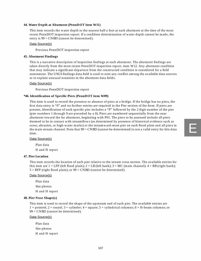
E
107
44. Water Depth at Abutment (PennDOT item W11)
This item records the water depth to the nearest half a foot at each abutment at the time of the mostrecent PennDOT inspection report. If a confident determination of water depth cannot be made, theentry is 99 = CNBD (cannot be determined).
Data Source(s)
Previous PennDOT inspection report
45. Abutment Findings
This is a narrative description of inspection findings at each abutment. The abutment findings aretaken directly from the most recent PennDOT inspection report, item W12. Any abutment conditionthat may indicate a significant departure from the constructed condition is considered for a fieldassessment. The USGS findings data field is used to note any conflict among the available data sourcesor to explain unusual notations in the abutment data fields.
Data Source(s)
Previous PennDOT inspection report
*46. Identification of Specific Piers (PennDOT item W09)
This item is used to record the presence or absence of piers at a bridge. If the bridge has no piers, thefirst data entry is “0” and no further entries are required in the Pier section of the form. If piers arepresent, identification of each specific pier includes a “P” followed by the 2 digit number of the pier(pier numbers 1 through 9 are preceded by a 0). Piers are numbered sequentially from the nearabutment toward the far abutment, beginning with P01. The piers to be assessed include all piersdeemed to be in contact with streamflows (as determined by presence of historical evidence such asscour, abrasion, or high-water marks) or the streamward-most pier on each flood plain and all piers inthe main stream channel. Note that 99 = CNBD (cannot be determined) is not a valid entry for this dataitem.
Data Source(s)
Plan dataH and H report
47. Pier Location
This item records the location of each pier relative to the stream cross section. The available entries forthis item are 1 = LFP (left flood plain); 2 = LB (left bank); 3 = MC (main channel): 4 = RB (right bank);5 = RFP (right flood plain); or 99 = CNBD (cannot be determined).
Data Source(s)
Plan dataSite photosH and H report
48. Pier Nose Shape(s)
This item is used to record the shape of the upstream end of each pier. The available entries are1 = pointed; 2 = round; 3 = cylinder; 4 = square; 5 = cylindrical columns; 6 = H-beam columns; or99 = CNBD (cannot be determined).
Data Source(s)
Plan dataSite photosH and H report
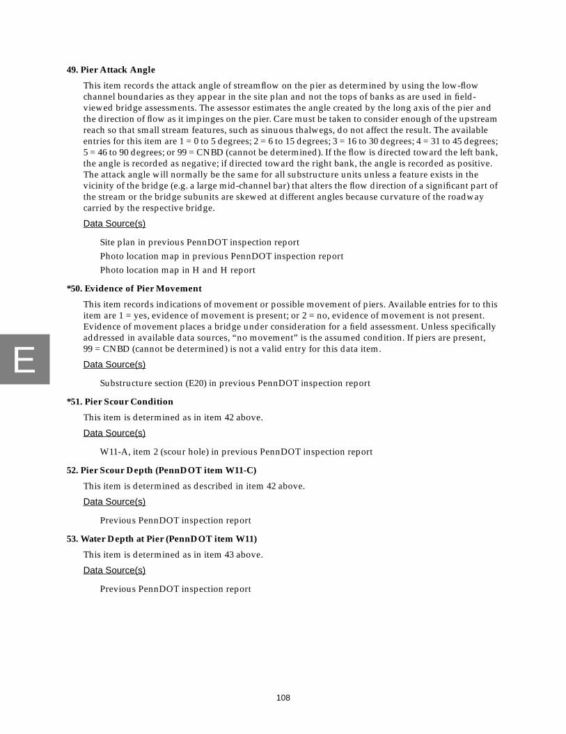
E
108
49. Pier Attack Angle
This item records the attack angle of streamflow on the pier as determined by using the low-flowchannel boundaries as they appear in the site plan and not the tops of banks as are used in field-viewed bridge assessments. The assessor estimates the angle created by the long axis of the pier andthe direction of flow as it impinges on the pier. Care must be taken to consider enough of the upstreamreach so that small stream features, such as sinuous thalwegs, do not affect the result. The availableentries for this item are 1 = 0 to 5 degrees; 2 = 6 to 15 degrees; 3 = 16 to 30 degrees; 4 = 31 to 45 degrees;5 = 46 to 90 degrees; or 99 = CNBD (cannot be determined). If the flow is directed toward the left bank,the angle is recorded as negative; if directed toward the right bank, the angle is recorded as positive.The attack angle will normally be the same for all substructure units unless a feature exists in thevicinity of the bridge (e.g. a large mid-channel bar) that alters the flow direction of a significant part ofthe stream or the bridge subunits are skewed at different angles because curvature of the roadwaycarried by the respective bridge.
Data Source(s)
Site plan in previous PennDOT inspection reportPhoto location map in previous PennDOT inspection reportPhoto location map in H and H report
*50. Evidence of Pier Movement
This item records indications of movement or possible movement of piers. Available entries for to thisitem are 1 = yes, evidence of movement is present; or 2 = no, evidence of movement is not present.Evidence of movement places a bridge under consideration for a field assessment. Unless specificallyaddressed in available data sources, “no movement” is the assumed condition. If piers are present,99 = CNBD (cannot be determined) is not a valid entry for this data item.
Data Source(s)
Substructure section (E20) in previous PennDOT inspection report
*51. Pier Scour Condition
This item is determined as in item 42 above.
Data Source(s)
W11-A, item 2 (scour hole) in previous PennDOT inspection report
52. Pier Scour Depth (PennDOT item W11-C)
This item is determined as described in item 42 above.
Data Source(s)
Previous PennDOT inspection report
53. Water Depth at Pier (PennDOT item W11)
This item is determined as in item 43 above.
Data Source(s)
Previous PennDOT inspection report

E
109
54. Pier Findings
This is a narrative description of inspection findings at each pier. The pier findings are taken directlyfrom PennDOT item W12 in the most recent PennDOT inspection report. Any pier condition that mayindicate a significant departure from the constructed condition is considered for a field-viewedassessment. The USGS findings field is used to note any conflict among the available data sources or toexplain unusual notations in the pier data fields.
Data Source(s)
Previous PennDOT inspection report
*55. Wingwalls
This item records the presence and condition of upstream left and right wingwalls and downstreamleft and right wingwalls. The available entries for the “Present” field are 0 = no (wingwall is notpresent but it would be advantageous if one existed); 1 = yes (wingwall is present); or 2 = no, notnecessary (wingwall is not present but is not required for bridge protection). The available entries forthe “Condition” field are 1 = good (the wingwall is providing adequate protection); 2 = partial (thewingwall is providing insufficient protection); or 3 = failed (the wingwall provides no protection).Comments indicating any significant condition present at or on a wingwall are noted in the commentfield provided. Note that 99 = CNBD (cannot be determined) is not a valid entry for this data item.Unless specifically described in the available PennDOT data sources the wingwall condition isassumed to be good.
Data Source(s)
Plan dataSite photographsSubstructure section (E20) of previous PennDOT inspection report
56. Scour Depths for 100-Year Flood
This item records whether the calculated scour depths for the 100-year flood event for eachsubstructure unit exceeds the bottom of footer elevation for that respective substructure unit(Richardson and others, 1993). The assessor records each subunit in the appropriate field. The channelelevation, the calculated scour depth, and bottom of footer elevation for each subunit are determinedfrom the available PennDOT data sources and recorded in the appropriate data fields. The entry forunavailable data is 99 = CNBD (cannot be determined). The assessor addresses “Are Calculated ScourDepths Below Bottom of Footer” data field with the following entries: 0 = no; 1 = yes; 2 = yes, foundedon bedrock (the calculated scour depth exceeds the PennDOT-supplied footer depth, but the subunit isfounded on scour-resistant bedrock); or 99 = CNBD (cannot be determined).
Data Source(s)
Plan dataH and H reportFoundation report
*57. PennDOT-Derived W11-A Table
Data to complete the PennDOT-derived W11-A table is copied directly from the W11-A table found inthe most recent PennDOT bridge inspection report. Note that 99 = CNBD (cannot be determined) isnot a valid entry for this data item.
Data Source(s)
Foundation report

E
110
58. Debris Accumulation
This item records the presence of a significant accumulation of debris within the bridge opening.The available entries for this item are 0 = no debris is present; or 1 = yes, debris is present. Unlessspecifically described to the contrary in the available PennDOT data sources, the assumed condition isno debris is present.
Data Source(s)
W11-A, item 3 (debris potential) in previous PennDOT inspection reportChannel/Channel Protection section of previous PennDOT inspection reportH and H report
59. Type of Debris
This item records the type of material that is the most significant constituent in the debrisaccumulation recorded in item 58, above. Available entries are 1 = brush; 2 = whole trees; 3 = trash;4 = all others; or 99 = CNBD (cannot be determined). This data field is left blank only if the entry initem 58 above is “no.”
Data Source(s)
Previous PennDOT inspection reportSite photographsH and H report
60. Trapping Potential
This item records the potential for the bridge to trap debris. As discussed previously, trappingpotential is affected by such factors as size of the bridge opening, sediment deposits, presence andorientation of piers, and attack angles. The available entries are 0 = low; 1 = medium; or 2 = high.
Data Source(s)
Plan dataW11-A, item 5 (opening adequacy) and item 6 (sediment deposits) in previous
PennDOT inspection report
61. Debris Potential
This item records a qualitative determination of the potential of the upstream drainage basin toproduce debris. Information that suggests the accumulation of extensive debris at a bridge site orevidence that indicates an abundance of debris nearby, results in the assumption that this basin hashigh potential for debris production. Extensive tree growth along the bank with some evidence ofundercutting also falls into the high potential category. Moderate tree growth along the bank or in theflood plain is considered medium debris potential. A bridge site with some woody vegetation andlittle or no apparent debris at the bank, in the stream, or on the flood plain is assigned the rating of lowdebris potential. Very large streams, very large drainage basins, and streams that flow through heavilyforested basins are rated as having high potential for debris production. At the other extreme, smallstreams and drainage basins with very little woody vegetation are assumed to have a low potential fordebris production. Available entries are 0 = low; 1 = medium; or 2 = high. If debris potential is notspecifically addressed in the H and H report, the assessor uses data transcribed from the W11-A entryfor the lowest rated (worst) subunit in the previous PennDOT inspection report
Data Source(s)
H and H reportW11-A, item 3 (debris potential) in previous PennDOT inspection reportSite photographs

E
111
62. Is the Structure Impacted by Ocean Tides
This item records whether the structure is affected by tidal conditions. Available entries are 0 = no, notaffected by tides; 1 = yes, affected by tides; or 99 = CNBD (cannot be determined).
Data Source(s)
H and H report
*63. Is Repair/Replace Listed as a Recommendation?
This item records whether repair and (or) replacement of abutment slopewalls, apron and (or) cutoffwalls, or streambed paving is recommended as a result of the most recent PennDOT inspection.Unless specifically reported to the contrary in the most recent PennDOT inspection report, or in theBMS data, it is assumed that repair and (or) replacement of the current countermeasures in notnecessary. Note that 99 = CNBD (cannot be determined) is not a valid entry for this data item.
Data Source(s)
Previous PennDOT inspection reportBMS data
64. Other Pertinent Data
This item records pertinent data not specifically addressed by the data-collection form.
65. Effects From Site Conditions and Other Structures
This item records any unusual site conditions resulting from bedrock banks or waterfalls, or otherstructures within two-bridge-lengths or 200 ft upstream and downstream from the bridge.This information can be obtained from any of the available PennDOT data sources.
66. Reason for Replacement/Renovation
This item lists the reason for major renovation or replacement of the previously existing bridge.Available entries for this item are 0 = new bridge at this site; 1 = insufficient roadway alignment;2 = new roadway alignment; 3 = insufficient load capacity; 4 = structural failure due to hydraulicconditions; 5 = structural failure due to non-hydraulic conditions; 6 = insufficient opening adequacy;7 = general structural deterioration; 8 = other; or 99 = CNBD (cannot be determined). An entry of“other” will receive a notation in the comment field. Bridges that receive an office-reviewed bridgeassessment because of limited accessibility will have an entry of “other” for this data field, and havethe appropriate notation added to the respective comment field.
Data Source(s)
H and H report
67. Do Site Conditions Warrant a Field Assessment
This item records whether the office-reviewed bridge site is reclassified as a field-viewed bridge site,at which time, USGS and (or) PennDOT personnel will visit the bridge site to collect morecomprehensive data. Entries from previously completed fields such as “Change Since LastInspection,” “Evidence of Movement,” and “W12 Findings” are used in this determination.Examples of conditions that warrant a field inspection are excessive blockage, significant failedcountermeasures, significant bank erosion, and possible impact on substructure. Available entries are0 = no field assessment necessary; or 1 = yes, field assessment recommended. If the entry recommendsa field assessment, the conditions that support this decision are noted in the respective comment field.An entry of 1 indicates PennDOT personnel and the appropriate USGS personnel are notified.Note that 99 = CNBD (cannot be determined) is not a valid entry for this data item.

113
F
APPENDIX FPROCEDURE FOR DETERMINATION OF THE SCOUR-CRITICAL
BRIDGE INDICATOR CODE FOR FIELD-VIEWED BRIDGE SITES

F
114
PROCEDURE FOR DETERMINATION OF THE SCOUR-CRITICAL BRIDGE INDICATORCODE FOR FIELD-VIEWED BRIDGE SITES
The Scour-Critical Bridge Indicator Code (Code) indicates the degree to which scour is currently afactor at the site and the vulnerability of the bridge to future scour. The code is computed using thefollowing flow charts (figs. 28 and 29) and tables 8 through 13. The Code ranges from code 9 to code 2 andrepresents the site conditions for the date of the assessment. As per the data-collection methods for field-viewed bridge sites, only subunits that meet criteria for scour assessments are coded; for example,expansive bridges that carry elevated roadways will be coded only on the basis of those subunits incontact with streamflow. The procedures described for determination of the Code for field-viewed bridgesites use USGS data and PennDOT BMS data to determine the code for subunits and, on the basis of themost vulnerable subunits for a bridge, the bridge structure is assigned an overall code. PennDOT BMSdata are compared with data observed by USGS for subunit type and subunit foundation type.The following flowchart and selection tables determine how these two data sources are used in thedetermination of the Code for the bridge site.
The Code is based on PennDOT BMS item W06. Item W06 is further defined in the PennDOT BridgeManagement System Coding Guide of 1993. The codes described in PennDOT item W06 are equivalent tothe codes described in the Federal Highway Administration (FHWA) database item I-113 (FederalHighway Administration report FHWA-ED-89-044: “Recording and Coding Guide for the StructureInventory and Appraisal of the Nation’s Bridges” 77p). In the past, PennDOT has added additionalclarification to the FHWA item descriptors as indicated in the notes for item W06 in the PennDOT BMSCoding Guide.
A subunit can only be coded if data are complete for the following USGS data fields:
subunit typesubunit foundation typescour conditionchange since last inspectionunder-the-bridge primary bed material OR streambed material near the subunitcondition of countermeasures at subunitrecommendations of possible countermeasures under bridgeevidence of movement
and the BMS data field:
C05A (Structural Configuration and Material Used for Main Unit and ApproachSpan)
The data field, streambed material near the subunit, was added to the field data-collection protocolin January 1996, therefore, the Code for bridges having field observations completed prior to that date aredetermined using the under-the-bridge primary bed material data field.

F
115
A subunit may meet the criteria for more than one code, however it receives the code that is closestto the top of the ordered list below. If a subunit meets the criteria for one or two cases within a specificcode, both cases for that code will be indicated to the user. A code of 6 indicates further evaluation isrequired for the subunit by PennDOT.
Code 6, cases 1-3Code 2Code 8Code 7Code 5Code 4Code 3Code 6, case 4
Because the subunits are components of the overall structure code, the overall bridge structurereceives the code equal to the code for the subunit rated closest to the top of the ordered list below.For example, if the three subunits for a bridge are rated 2, 6 case 3, and 5, the bridge structure receives acode of 6.
Code 6Code 2Code 3Code 4Code 5Code 7Code 8
Pier type and pier foundation type data are stored in the PennDOT BMS database in items C39 andC40, respectively. These two items contain four subfields each in which PennDOT personnel enter pierdata. The following assumptions must be made for use of BMS pier data in determining the Code forbridges:
1. If only 1 set of pier data (1 subfield complete for pier type and 1 subfield completefor foundation type) is available, assume that these data apply to all piers for thebridge.For example; all piers of a bridge structure are constructed of the same type ofmaterial with the same foundation type, therefore, only one entry is made in the BMSdatabase to describe all piers.
2. If the number of subfields of pier data equal the number of piers, assume that firstsubfield describes P01, the second subfield describes P02, and so on. For example; thevariation among piers of a specific bridge is substantial enough to warrantindividual entries for each pier and the overall number of piers does not exceed thecapacity of the BMS data base to contain the associated data.
3. If no data are available for piers or if data can not be assigned to specific piersaccording to assumptions 1 and 2 above, the subunit can not be coded and receivesa code of 6.For example; PennDOT, when required, uses a description of groups of piers withsimilar characteristics in the BMS database. These group descriptions cannot be usedfor completion of the Rating and Code and, therefore, these bridge sites requiremanual computation by PennDOT personnel.

F
116
When BMS data for foundation type or subunit type are blank, indicated as “other,” or when thefoundation type is “not determined,” the subunit receives a code of 6. In rare cases, a subunit may notmeet the criteria for codes 9-7 or 5-2 because of other circumstances as noted in the following flowchart,tables, and list of criteria; in this case, the subunit and the bridge are assigned a code of 6.
Several combinations of subunit types and foundation types cannot occur in the construction of abridge (tables 11 and 12). In these cases, the subunit receives a code of 6 to indicate that further evaluationby PennDOT is required. For example, a bridge may be supported by a temporary substructure unit priorto repair.
For cases where a foundation type of “not observed” is used in the determination of the Code,a foundation type of alluvium is used for that specific subunit. An alluvium foundation type is considereda worst-case scenario. In reality, the foundation type may be more stable and requires further investi-gation. Comments in the USGS database or in the BMS database must be consulted for additionalinformation.
Several combinations of conflicting data are flagged to alert the user that a more thorough review isrequired than for sites where data are similar or compatible. The flag states that a special condition at thissite requires PennDOT review. Other site conditions are flagged as indicated in the coding criteria below.The combinations of conflicting codes that are flagged are:
1. USGS foundation type = bedrockBMS foundation type = L
2. USGS foundation type = piles/caissonsBMS foundation type = A, R
3. USGS foundation type = otherBMS foundation type = A, R, K, B-J, S, L.

F
117
Figure 28. Determination of Scour-Critical Bridge Indicator Code for abutments at field-viewed bridge sites.
Are BMS data for abutmenttype = blank or 9?
Select code abutment type (useTable 8 for USGS abutment type
and BMS abutment type)
Are BMS data for abutmentfoundation type = blank or O?
Is USGS abutment foundation
Is BMS abutment foundationtype = P, X?
Select code abutment foundationtype (use Table 10 for USGS
abutment foundation type and
type = not observed?
BMS abutment foundation type)
YES
NO
NO
NO
NO
YES
YES
YES
subunitcode 6case 1
assign
subunitcode 6case 1
assign
subunitcode 6case 1
assign
Are code abutment type andcode abutment foundation type
combination in Table 11?
subunitcode 6case 3
assignYES

F
118
Are anycriteria
flagged?Meet criteria for one ormore cases of code 2?
Are any data combinations
BedrockPiles/CaissonsOther
LA, RA, R, K, B-J, S, L
flagfinal
results
flagfinal
results(flag #1)
no flag
NO
NO
NO
YESassign
code 2
YESUSGS abutmentfoundation type
BMS abutmentfoundation type
for subunit as below?:
subunit
Are anycriteria
flagged?Meet criteria for one ormore cases of code 8?
no flag
YESassign
code 8subunit
Are anycriteria
flagged?Meet criteria for one ormore cases of code 7?
no flag
YESassign
code 7subunit
NO
Are anycriteria
flagged?Meet criteria for one ormore cases of code 5?
no flag
YESassign
code 5subunit
NO
NO
andcase(s)
andcase(s)
andcase(s)
andcase(s) flag
finalresults
flagfinal
results
flagfinal
results
Figure 28. Determination of Scour-Critical Bridge Indicator Code for abutments at field-viewed bridge sites—Continued.
YES
YES
YES
YES
NO
NO
NO
NO

F
119
NO
Are anycriteria
flagged?Meet criteria for one ormore cases of code 3?
no flag
YESassign
code 3subunit
NO
Are anycriteria
flagged?Meet criteria for one ormore cases of code 4?
no flag
YESassign
code 4subunit
NO
subunitcode 6case 4
assign
andcase(s)
andcase(s) flag
finalresults
flagfinal
results
Figure 28. Determination of Scour-Critical Bridge Indicator Code for abutments at field-viewed bridge sites—Continued.
YES
NO
YES
NO

F
120
Figure 29. Determination of Scour-Critical Bridge Indicator Code for piers at field-viewed bridge sites.
Are BMS data forpier type blank?
(all C39 fields = blank)
Are BMS data forpier foundation type blank?
(all C40 fields = blank)
Can BMS data forpier type be assigned topier according to rules?
Can BMS data for pierfoundation type be assigned to
pier according to rules?
Is BMS pier type = 9?
Select code pier type(use Table 9 for USGS
pier type and BMS pier type)
Is BMS pier foundation
YES
YES
NO
YES
YES
NO
NO
YES
NO
YES
NO
NO
type = O?
Assign BMS pier type tosubunit according to rules
Assign BMS pier foundationtype to subunit according
to rules
assignsubunitcode 6case 1
assignsubunitcode 6case 1
assignsubunitcode 6case 2
assignsubunitcode 6case 1
assignsubunitcode 6case 2
assignsubunitcode 6case 1

F
121
Is USGS pier foundation
Is BMS pier foundationtype = P, X?
Select code pier foundationtype (use Table 10 for USGS
foundation type and
type = not observed?
BMS foundation type)
NO
NO
NO
YES
YES
assign
code 6case 1
subunit
Are code pier type andcode pier foundation type
combination in Table 12?
Are any data combinations
BedrockPiles/CaissonsOther
LA, RA, R, K, B-J, S, L
flagfinal
results(flag #1)
YESUSGS pierfoundation type
BMS pierfoundation type
for subunit as below?:
NO
NO
assign
code 6case 3
subunitYES
Are anycriteria
flagged?Meet criteria for one ormore cases of code 2?
no flag
YESassign
code 2subunit
NO
andcase(s) flag
finalresults
Figure 29. Determination of Scour-Critical Bridge Indicator Code for piers at field-viewed bridge sites—Continued.
YES
NO

F
122
Are anycriteria
flagged?Meet criteria for one ormore cases of code 8?
no flag
YESassign
code 8subunit
Are anycriteria
flagged?Meet criteria for one ormore cases of code 7?
no flag
YESassign
code 7subunit
NO
Are anycriteria
flagged?Meet criteria for one ormore cases of code 5?
no flag
YESassign
code 5subunit
NO
NO
Are anycriteria
flagged?Meet criteria for one ormore cases of code 3?
no flag
YESassign
code 3subunit
NO
Are anycriteria
flagged?Meet criteria for one ormore cases of code 4?
no flag
YESassign
code 4subunit
NO
andcase(s)
andcase(s)
andcase(s)
andcase(s)
andcase(s)
NO
flagfinal
results
flagfinal
results
flagfinal
results
flagfinal
results
Figure 29. Determination of Scour-Critical Bridge Indicator Code for piers at field-viewed bridge sites—Continued.
flagfinal
results
YES
NO
YES
NO
YES
NO
YES
NO
YES
NO

F
123
subunitcode 6case 4
assign
NO
Figure 29. Determination of Scour-Critical Bridge Indicator Code for piers at field-viewed bridge sites—Continued.

124
F
Table 8. Selection of abutment type used in the Scour-Critical Bridge Indicator Code for field-viewed bridge sites
[w/o, without; 6.1 indicates that no choice of abutment type is necessary, subunit is coded 6.1]
USGS Type →1 2 3 4 5 6 7 8 9 10
BMS Type ↓
1 stub (1) cantilever (2) gravity concrete (3) spill-through (4) unknownconcrete (5)
stone masonry (6) piles/bents (7) concrete w/opiles/bents (8)
mechanicallystabilizedearth (9)
stub (1)
2 stub (1) cantilever (2) gravity concrete (3) spill-through (4) unknownconcrete (5)
stonemasonry (6)
piles/bents (7) concrete w/opiles/bents (8)
mechanicallystabilizedearth (9)
cantilever (2)
3 stub (1) cantilever(2) gravity concrete (3) spill-through (4) unknownconcrete (5)
stonemasonry (6)
piles/bents (7) concrete w/opiles/bents (8)
mechanicallystabilizedearth (9)
gravityconcrete (3)
4 stub (1) cantilever(2) gravity concrete (3) spill-through (4) unknownconcrete (5)
stonemasonry (6)
piles/bents (7) concrete w/opiles/bents (8)
mechanicallystabilizedearth (9)
stone masonry (6)
5 stub (1) cantilever(2) gravity concrete (3) spill-through (4) unknownconcrete (5)
stonemasonry (6)
piles/bents (7) concrete w/opiles/bents (8)
mechanicallystabilizedearth (9)
gravityconcrete (3)
6 stub (1) cantilever(2) gravity concrete (3) spill-through (4) unknownconcrete (5)
stonemasonry (6)
piles/bents (7) concrete w/opiles/bents (8)
mechanicallystabilizedearth (9)
stub (1)
7 stub (1) cantilever(2) gravity concrete (3) spill-through (4) unknownconcrete (5)
stonemasonry (6)
piles/bents (7) concrete w/opiles/bents (8)
mechanicallystabilizedearth (9)
mechanicallystabilizedearth (9)
8 stub (1) cantilever(2) gravity concrete (3) spill-through (4) unknownconcrete (5)
stonemasonry (6)
piles/bents (7) concrete w/opiles/bents (8)
mechanicallystabilizedearth (9)
spill-through (4)
9 6.1 6.1 6.1 6.1 6.1 6.1 6.1 6.1 6.1 6.1
A stub (1) cantilever(2) gravity concrete (3) spill-through (4) unknownconcrete (5)
stonemasonry (6)
piles/bents (7) concrete w/opiles/bents (8)
mechanicallystabilizedearth (9)
mechanicallystabilizedearth (9)
B stub (1) cantilever(2) gravity concrete (3) spill-through (4) unknownconcrete (5)
stonemasonry (6)
piles/bents (7) concrete w/opiles/bents (8)
mechanicallystabilizedearth (9)
mechanicallystabilizedearth (9)
C stub (1) cantilever(2) gravity concrete (3) spill-through (4) unknownconcrete (5)
stonemasonry (6)
piles/bents (7) concrete w/opiles/bents (8)
mechanicallystabilizedearth (9)
mechanicallystabilizedearth (9)

125
F
D stub (1) cantilever(2) gravity concrete (3) spill-through (4) unknownconcrete (5)
stone masonry (6) piles/bents (7) concrete w/opiles/bents (8)
mechanicallystabilizedearth (9)
other (10)
E stub (1) cantilever(2) gravity concrete (3) spill-through (4) unknownconcrete (5)
stone masonry (6) piles/bents (7) concrete w/opiles/bents (8)
mechanicallystabilizedearth (9)
piles/bents (7)
F stub (1) cantilever(2) gravity concrete (3) spill-through (4) unknownconcrete (5)
stone masonry (6) piles/bents (7) concrete w/opiles/bents (8)
mechanicallystabilizedearth (9)
other (10)
G stub (1) cantilever(2) gravity concrete (3) spill-through (4) unknownconcrete (5)
stone masonry (6) piles/bents (7) concrete w/opiles/bents (8)
mechanicallystabilizedearth (9)
stone masonry (6)
H stub (1) cantilever(2) gravity concrete (3) spill-through (4) unknownconcrete (5)
stone masonry (6) piles/bents (7) concrete w/opiles/bents (8)
mechanicallystabilizedearth (9)
mechanicallystabilizedearth (9)
I stub (1) cantilever(2) gravity concrete (3) spill-through (4) unknownconcrete (5)
stone masonry (6) piles/bents (7) concrete w/opiles/bents (8)
mechanicallystabilizedearth (9)
mechanicallystabilizedearth (9)
J stub (1) cantilever(2) gravity concrete (3) spill-through (4) unknownconcrete (5)
stone masonry (6) piles/bents (7) concrete w/opiles/bents (8)
mechanicallystabilizedearth (9)
mechanicallystabilizedearth (9)
K stub (1) cantilever(2) gravity concrete (3) spill-through (4) unknownconcrete (5)
stone masonry (6) piles/bents (7) concrete w/opiles/bents (8)
mechanicallystabilizedearth (9)
other (10)
L stub (1) cantilever(2) gravity concrete (3) spill-through (4) unknownconcrete (5)
stone masonry (6) piles/bents (7) concrete w/opiles/bents (8)
mechanicallystabilizedearth (9)
other (10)
X stub (1) cantilever(2) gravity concrete (3) spill-through (4) unknownconcrete (5)
stone masonry (6) piles/bents (7) concrete w/opiles/bents (8)
mechanicallystabilizedearth (9)
unknownconcrete (5)
Y stub (1) cantilever(2) gravity concrete (3) spill-through (4) unknownconcrete (5)
stone masonry (6) piles/bents (7) concrete w/opiles/bents (8)
mechanicallystabilizedearth (9)
spill-through (4)
Z stub (1) cantilever(2) gravity concrete (3) spill-through (4) unknownconcrete (5)
stone masonry (6) piles/bents (7) concrete w/opiles/bents (8)
mechanicallystabilizedearth (9)
mechanicallystabilizedearth (9)
blank 6.1 6.1 6.1 6.1 6.1 6.1 6.1 6.1 6.1 6.1
Table 8. Selection of abutment type used in the Scour-Critical Bridge Indicator Code for field-viewed bridge sites—Continued
[w/o, without; 6.1 indicates that no choice of abutment type is necessary, subunit is coded 6.1]
USGS Type →1 2 3 4 5 6 7 8 9 10
BMS Type ↓

F
126
Table 9. Selection of pier type used in the Scour-Critical Bridge Indicator Code forfield-viewed bridge sites
[6.1 indicates that no choice of pier type is necessary, subunit is coded 6.1]
USGS Type →1 2 3 4 5
BMS Type ↓
1 timber (1) steel (2) concrete (3) stone masonry (4) timber (1)
2 timber (1) steel (2) concrete (3) stone masonry (4) steel (2)
3 timber (1) steel (2) concrete (3) stone masonry (4) concrete (3)
4 timber (1) steel (2) concrete (3) stone masonry (4) concrete (3)
5 timber (1) steel (2) concrete (3) stone masonry (4) concrete (3)
6 timber (1) steel (2) concrete (3) stone masonry (4) stone masonry (4)
7 timber (1) steel (2) concrete (3) stone masonry (4) concrete (3)
9 timber (1) steel (2) concrete (3) stone masonry (4) other (5)
Blank 6.1 6.1 6.1 6.1 6.1
Table 10. Selection of abutment and pier foundation type used in the Scour-Critical Bridge Indicator Codefor field-viewed bridge sites
[6.1 indicates that no choice of abutment and pier foundation type is necessary, subunit is coded 6.1]
USGS Type →1 2 3 4 5
BMS Type ↓
A bedrock (1) bedrock (1) piles/caissons (3) bedrock (1) bedrock (1)B-J piles/caissons (3) piles/caissons (3) piles/caissons (3) piles/caissons (3) piles/caissons (3)K alluvium (2) alluvium (2) piles/caissons (3) alluvium (2) alluvium (2)L bedrock (1) alluvium (2) piles/caissons (3) alluvium (2) alluvium (2)O / blank 6.1 6.1 6.1 6.1 6.1P 6.1 6.1 6.1 6.1 not observed (5)R bedrock (1) bedrock (1) piles/caissons (3) bedrock (1) bedrock (1)S piles/caissons (3) piles/caissons (3) piles/caissons (3) piles/caissons (3) piles/caissons (3)X 6.1 6.1 6.1 6.1 not observed (5)

F
127
Table 11. Incompatible combinations of abutment types and foundation typesin the Scour-Critical Bridge Indicator Code for field-viewed bridge sites
[w/o, without]
Abutment Type Abutment Foundation Type
stub (1) alluvium (2)stub (1) not observed (5)piles/bents (7) bedrock (1)piles/bents (7) alluvium (2)piles/bents (7) not observed (5)concrete w/o piles/bents (8) piles/caissons (3)other (10) bedrock (1)other (10) alluvium (2)other (10) piles/caissons (3)other (10) not observed (5)
Table 12. Incompatible combinations of piertypes and foundation types in the Scour-CriticalBridge Indicator Code for field-viewed bridge sites
Pier type Pier foundation type
steel (2) bedrock (1)steel (2) alluvium (2)steel (2) not observed (5)other (5) bedrock (1)other (5) alluvium (2)other (5) piles/caissons (3)other (5) not observed (5)

F
128
Table 13. Criteria for determination of Scour-Critical Bridge Indicator Code for field-viewed bridge sites
Use the following subunit type and foundation type selections in the criteria that follows:
All other site data are located on the form: “Bridge and Channel Characteristics at Field-ViewedBridge Sites” (Appendix A).
CODE 9
Only PennDOT District personnel assign Code 9 to bridges.
CASE 1
Criteria
Bridge over high gorge, all subunits are above the 500-year flood elevation.
CASE 2
Criteria
Bridge over roads or railroads where the channel is small and does not threaten the sub-units.
Abutment type: Pier type:
1 = stub 1 = timber2 = cantilever 2 = steel3 = gravity concrete 3 = concrete4 = spill-through 4 = stone5 = unknown concrete 5 = other6 = stone masonry7 = piles/bents8 = concrete without piles/bents9 = mechanically stabilized earth10 = other
abutment and pier foundation type:
1 = bedrock2 = alluvium3 = piles/caissons5 = not observed

F
129
Table 13. Criteria for determination of Scour-Critical Bridge Indicator Code for field-viewed bridge sites —Continued
CODE 8
Code 8 indicates bridges classified as culverts by PennDOT or subunits founded oncompetent bedrock.
CASE 1
Criteria
1. BMS C05A (digits 4 and 5) = 30, 31, 32, 33, 34, 35
2. scour condition = 0, 1, 2, 3
3. movement = 0
4. change since last inspection = 4, 5, 6, 7, 8, 9
Flag
1. scour condition = 3AND (OR)
2. change since last inspection = 4, 5, 6
CASE 2
Criteria
1. abutment foundation type = 1
2. abutment type = 1, 2, 3, 4, 5, 6
OR1. pier foundation type = 1
2. pier type = 1, 3, 4
AND
3. scour condition = 0, 1, 2
4. movement = 0
5. change since last inspection = 4, 5, 6, 7, 8, 9
6. streambed material near the subunit = A3, A4, A5, A6, R7, R8, R9, P7, P8
If 6. not available, subunit coded based on criteria 1 - 5 above only.
Flag
1. change since last inspection = 4, 5, 6

F
130
Table 13. Criteria for determination of Scour-Critical Bridge Indicator Code for field-viewed bridge sites—Continued
CODE 8—Continued
CASE 3
Criteria
1. abutment foundation type = 5
2. abutment type = 2, 3, 4, 5, 6
OR1. pier foundation type = 5
2. pier type = 1, 3, 4
AND
3. scour condition = 0, 1, 2
4. movement = 0
5. change since last inspection = 4, 5, 6, 7, 8, 9
6. under-the-bridge primary bed material = 5
Flag
1. change since last inspection = 4, 5, 6
CASE 4
Criteria
1. abutment foundation type = 3
2. abutment type = 1, 2, 3, 4, 5, 6, 7
OR1. pier foundation type = 3
2. pier type = 1, 2, 3, 4
AND
3. scour condition = 0, 1
4. movement = 0
5. change since last inspection = 7, 8, 9
6A. streambed material near the subunit = A5, A6
If 6A. not available, use 6B.:6B. under-the-bridge primary bed material = 4

F
131
Table 13. Criteria for determination of Scour-Critical Bridge Indicator Code for field-viewed bridge sites—Continued
CODE 7
Code 7 indicates subunits that are adequately protected by countermeasures.
CASE 1
Criteria
1. condition of all under-the-bridge countermeasures at the subunit = 1
2. scour condition = 0, 1, 2
3. movement = 0
4. change since last inspection = 4, 5, 6, 7, 8, 9
Flag
1. change since last inspection = 4, 5, 6
CASE 2
Criteria
1. none of the listed possible countermeasures are recommended at the subunit ORunder the bridge:
2. scour condition = 0, 1, 2
3. movement = 0
4. change since last inspection = 4, 5, 6, 7, 8, 9
5A. streambed material near the subunit = P7, P8
If 5A. not available, use 5B.:5B. under-the-bridge primary bed material = 6
Flag
1. change since last inspection = 4, 5, 6
POSSIBLE COUNTERMEASURES LOCATION
Footing underpinning [at subunit]Abutment slopewall (repair/replace) [at subunit]Streambed paving (repair/replace) UNRock protection UNScour hole (backfill) UNApron/cutoff wall (repair/replace) Inlet/Outlet

F
132
Table 13. Criteria for determination of Scour-Critical Bridge Indicator Code for field-viewed bridge sites—Continued
CODE 6
CASE 1
Criteria
For subunits for which BMS data for subunit type or subunit foundation type is blank, notdetermined, or other.
CASE 2
Criteria
For piers for which BMS data for pier type and/or pier foundation type could not be iden-tified to a specific pier.
CASE 3
Criteria
For subunits for which BMS data and USGS data for subunit type and subunit foundationtype are incompatible.
CASE 4
Criteria
For subunits that do not meet any case criteria for assigning codes 2-5, 7-8, code 6 cases1-3.

F
133
Table 13. Criteria for determination of Scour-Critical Bridge Indicator Code for field-viewed bridge sites—Continued
CODE 5
Code 5 indicates subunits in contact with streambed material consisting predominantly ofcobbles and boulders and showing little or no evidence of streambed instability.
CASE 1
Criteria
1. abutment foundation type = 2, 5
2. abutment type = 2, 3, 4, 5
OR1. pier foundation type = 2, 5
2. pier type = 3
AND
3. scour condition = 0, 1
4. movement = 0
5. change since last inspection = 7, 8, 9
6A. streambed material near the subunit = A5, A6, R7, R8
If 6A. not available, use 6B.:6B. under-the-bridge primary bed material = 4, 5
CASE 2
Criteria
1. abutment foundation type = 1
2. abutment type = 1, 2, 3, 4, 5
OR1. pier foundation type = 1
2. pier type = 3
AND
3. scour condition = 0, 1
4. movement = 0
5. change since last inspection = 7, 8, 9
6. streambed material near the subunit = R4
If 6. not available, criteria for this case can not be met

F
134
Table 13. Criteria for determination of Scour-Critical Bridge Indicator Code for field-viewed bridge sites—Continued
CODE 5—Continued
CASE 3
Criteria
1. abutment foundation type = 3
2. abutment type = 1, 2, 3, 4, 5, 7
OR1. pier foundation type = 3
2. pier type = 2, 3
AND
3. scour condition = 0, 1, 2
4. movement = 0
5. change since last inspection = 7, 8, 9
6A. streambed material near the subunit = A5, A6
If 6A. not available, use 6B.:6B. under-the-bridge primary bed material = 4

F
135
Table 13. Criteria for determination of Scour-Critical Bridge Indicator Code for field-viewed bridge sites—Continued
CODE 4
Code 4 indicates subunits in contact with streambed material consisting predominately ofcobbles and boulders, and showing some evidence of streambed instability.
CASE 1
Criteria
1. abutment foundation type = 2, 5
2. abutment type = 2, 3, 4, 5
OR1. pier foundation type = 2, 5
2. pier type = 3
AND
3. scour condition = 0, 1, 2
4. movement = 0
5. change since last inspection = 4, 5, 6, 7, 8, 9
6A. streambed material near the subunit = A5, A6, R7, R8
If 6A. not available, use 6B.:6B. under-the-bridge primary bed material = 4, 5
CASE 2
Criteria
1. abutment foundation type = 1
2. abutment type = 1, 2, 3, 4, 5
OR1. pier foundation type = 1
2. pier type = 3
AND
3. scour condition = 0, 1, 2
4. movement = 0
5. change since last inspection = 4, 5, 6, 7, 8, 9
6. streambed material near the subunit = R4
If 6. not available, criteria for this case can not be met

F
136
Table 13. Criteria for determination of Scour-Critical Bridge Indicator Code for field-viewed bridge sites—Continued
CODE 4—Continued
CASE 3
Criteria
1. abutment foundation type = 3
2. abutment type = 1, 2, 3, 4, 5, 7
OR1. pier foundation type = 3
2. pier type = 2, 3
AND
3. scour condition = 0, 1, 2, 3
4. movement = 0
5. change since last inspection = 4, 5, 6, 7, 8, 9
6A. streambed material near the subunit = A5, A6
If 6A. not available, use 6B.:6B. under-the-bridge primary bed material = 4
Flag
1. scour condition = 3
CASE 4
Criteria
1. abutment foundation type = 3
2. abutment type = 1, 2, 3, 4, 5, 7
OR1. pier foundation type = 3
2. pier type = 2, 3
AND
3. scour condition = 0, 1, 2, 3
4. movement = 0
5. change since last inspection = 7, 8, 9
6A. streambed material near the subunit = A3, A4
If 6A. not available, use 6B.:6B. under-the-bridge primary bed material = 1, 2, 3
CASE 5
Criteria
1. abutment type = 9
2. scour condition = 0
3. movement = 0

F
137
Table 13. Criteria for determination of Scour-Critical Bridge Indicator Code for field-viewed bridge sites—Continued
CODE 4—Continued
CASE 6
Criteria
1. abutment foundation type = 2, 5
2. abutment type = 6
OR1. pier foundation type = 2, 5
2. pier type = 1, 4
AND
3. scour condition = 0, 1
4. movement = 0
5. change since last inspection = 7, 8, 9
6A. streambed material near the subunit = A5, A6, R7, R8
If 6A. not available, use 6B.:6B. under-the-bridge primary bed material = 4, 5
CASE 7
Criteria
1. abutment foundation type = 1
2. abutment type = 6
OR1. pier foundation type = 1
2. pier type = 1, 4
AND
3. scour condition = 0, 1, 2
4. movement = 0
5. change since last inspection = 7, 8, 9
6. streambed material near the subunit = R4
If 6. not available, criteria for this case can not be met

F
138
Table 13. Criteria for determination of Scour-Critical Bridge Indicator Code for field-viewed bridge sites—Continued
CODE 4—Continued
CASE 8
Criteria
1. abutment foundation type = 3
2. abutment type = 6
OR1. pier foundation type = 3
2. pier type = 1, 4
AND
3. scour condition = 0, 1, 2
4. movement = 0
5. change since last inspection = 4, 5, 6, 7, 8, 9
6. streambed material near the subunit = A5, A6
If 6A. not available, use 6B.:6B. under-the-bridge primary bed material = 4
CASE 9
Criteria
1. abutment foundation type = 3
2. abutment type = 6
OR1. pier foundation type = 3
2. pier type = 1, 4
AND
3. scour condition = 0, 1, 2
4. movement = 0
5. change since last inspection = 7, 8, 9
6. streambed material near the subunit = A3, A4
If 6A. not available, use 6B.:6B. under-the-bridge primary bed material = 1, 2, 3

F
139
Table 13. Criteria for determination of Scour-Critical Bridge Indicator Code for field-viewed bridge sites—Continued
CODE 3
Code 3 indicates subunits in contact with streambed material consisting predominantly oferodible, fine material.
CASE 1
Criteria
1. abutment foundation type = 2, 5
2. abutment type = 2, 3, 4, 5
OR
1. pier foundation type = 2, 5
2. pier type = 3
AND
3. scour condition = 0, 1, 2
4. movement = 0
5. change since last inspection = 4, 5, 6, 7, 8, 9
6A. streambed material near the subunit = A3, A4, R4
If 6A. not available, use 6B.:
6B. under-the-bridge primary bed material = 1, 2, 3
CASE 2
Criteria
1. abutment foundation type = 3
2. abutment type = 1, 2, 3, 4, 5, 7
OR
1. pier foundation type = 3
2. pier type = 2, 3
AND
3. scour condition = 0, 1, 2, 3
4. movement = 0
5. change since last inspection = 4, 5, 6, 7, 8, 9
6A. streambed material near the subunit = A3, A4
If 6A. not available, use 6B.:
6B. under-the-bridge primary bed material = 1, 2, 3

F
140
Table 13. Criteria for determination of Scour-Critical Bridge Indicator Code for field-viewed bridge sites—Continued
CODE 3—Continued
CASE 3
Criteria
1. abutment type = 9
2. scour condition = 1
3. movement = 0
4. change since last inspection = 4, 5, 6, 7, 8, 9
CASE 4
Criteria
1. abutment foundation type = 2, 5
2. abutment type = 6
OR1. pier foundation type = 2, 5
2. pier type = 1, 4
AND
3. scour condition = 0, 1, 2
4. movement = 0
5. change since last inspection = 4, 5, 6, 7, 8, 9
6A. streambed material near the subunit = A3, A4, A5, A6, R4
If 6A. not available, use 6B.:6B. under-the-bridge primary bed material = 1, 2, 3, 4
CASE 5
Criteria
1. abutment foundation type = 1
2. abutment type = 6
OR1. pier foundation type = 1
2. pier type = 1, 4
AND
3. scour condition = 0, 1, 2
4. movement = 0
5. change since last inspection = 4, 5, 6, 7, 8, 9
6. streambed material near the subunit = R4
If 6. not available, criteria for case can not be met

F
141
Table 13. Criteria for determination of Scour-Critical Bridge Indicator Code for field-viewed bridge sites—Continued
CODE 3—Continued
CASE 6
Criteria
1. abutment foundation type = 1
2. abutment type = 1, 2, 3, 4, 5
OR1. pier foundation type = 1
2. pier type = 3
AND
3. scour condition = 3
4. movement = 0
5. change since last inspection = 4, 5, 6, 7, 8, 9
Flag
For all criteria
CASE 7
Criteria
1. abutment foundation type = 3
2. abutment type = 6
OR1. pier foundation type = 3
2. pier type = 1, 4
AND
3. scour condition = 0, 1, 2
4. movement = 0
5. change since last inspection = 4, 5, 6, 7, 8, 9
6A. streambed material near the subunit = A3, A4
If 6A. not available, use 6B.:6B. under-the-bridge primary bed material = 1, 2, 3

F
142
Table 13. Criteria for determination of Scour-Critical Bridge Indicator Code for field-viewed bridge sites—Continued
CODE 2
Code 2 indicates subunits having critical site conditions related to scour, such as; movementof the subunit, significant change since last inspection, or scour condition for foundation that
potentially threatens bridge structure.
CASE 1
Criteria
1. abutment type = 9
2. scour condition = 2, 3
CASE 2
Criteria
1. movement = 1
CASE 3
Criteria
1. abutment foundation type = 2, 5
2. abutment type = 2, 3, 4, 5
OR
1. pier foundation type = 2, 5
2. pier type = 3
AND
3. scour condition = 3
CASE 4
Criteria
1. abutment type = 6OR
1. pier type = 1, 4AND
2. scour condition = 3
CASE 5
Criteria
1. abutment type = 8
CASE 6
Criteria
1. change since last inspection = 3
Flag
For all criteria

143
G
APPENDIX GPROCEDURE FOR DETERMINATION OF THE SCOUR-CRITICAL
BRIDGE INDICATOR CODE FOR OFFICE-REVIEWED BRIDGE
SITES

G
144
PROCEDURE FOR DETERMINATION OF THE SCOUR-CRITICAL BRIDGE INDICATORCODE FOR OFFICE-REVIEWED BRIDGE SITES
The Scour-Critical Bridge Indicator Code (Code) for office-reviewed bridge sites serves the samepurpose as that for field-viewed bridge sites. The Code is computed using the following flowcharts(figs. 30 and 31) and tables 14 through 17. The Code ranges from code 9 to code 2 and represents the siteconditions based on existing PennDOT data compiled from PennDot data sources. As per the data-collection methods for office-reviewed bridge sites, only subunits that meet criteria for scour assessmentsare coded; for example, expansive bridges that carry elevated roadways will be coded only for thosesubunits that are in contact with streamflow.
Existing PennDOT data as compiled by the USGS during the office-review is used for thedetermination of the Code for office-reviewed bridge sites. This data is date specific for the date PennDOTpersonnel collected the data. Any discrepancies existing between various PennDOT data sources areresolved with the assistance of PennDOT district personnel during the office-review. The entire bridgestructure is assigned a code based on the code received by the most scour vulnerable (worst) subunit.
A subunit can only be coded if PennDOT data are available for the following data fields:
subunit typesubunit foundation typescour conditionchange since last inspectionunder-the-bridge primary bed material OR streambed material near the subunitcondition of countermeasures at subunitrecommendations of possible countermeasures under bridgeevidence of movementC05A (Structural Configuration and Material Used for Main Unit and Approach
Span)
The abutment type, pier type, and foundation types used to compute the Code are determinedthrough the use of a flowchart and tables 14 through 17. Subunit types and foundation types described as“other” within the tables receive a code of 6. Subunits that do not meet the criteria for codes 2 through 5 or7 through 9 are also assigned a code of 6. A code of 6 indicates that further evaluation of site conditions byPennDOT personnel is required. Unusual site conditions are defined and assigned a flag. A flag indicatesthat a special condition exists at this bridge site that requires further PennDOT review.

G
145
An individual subunit may meet the criteria for more than one code, however it receives the codethat is closest to the top of the ordered list below. If a subunit meets the criteria for one or two cases withina specific code, both cases for that code will be indicated to the user.
Code 6, case 1Code 2Code 8Code 7Code 5Code 4Code 3Code 6, case 4
Because individual subunits are only components of the overall bridge structure, the bridgestructure receives the code assigned to the subunit rated closest to the top of the ordered list below.For example, if the three subunits for a bridge are rated 2, 6 case 1, and 5, the overall bridge structurereceives a code of 6.
Code 6Code 2Code 3Code 4Code 5Code 7Code 8

G
146
Code 6Case 1
YES
No flagCode 8
NO
Code 2 Are any criteria flagged?
YES
NO Flag final
Based on existing PennDOT data,assign abutment typefrom table 14.
Can abutment typebe assigned?
Based on existing PennDOT data,assign abutment foundationtype from table 16.
Can foundation type be assigned?
Does abutment meet
Does abutment meetcriteria for Code 8?
criteria for Code 2?
NO
YES
Code 6Case 1
YES
NO
NO
YES
results
Figure 30. Determination of Scour-Critical Bridge Indicator Code for abutments at office-reviewed bridge sites.

G
147
AssignCode 6Case 4
Code 3
NO
Code 4
Code 5
YES
Does abutment meetcriteria for Code 5?
Does abutment meetcriteria for Code 4?
Does abutment meetcriteria for Code 3?
Flag finalresults
Are any criteria flagged?
No flag
Does abutment meetcriteria for Code 7? Code 7
NO
YES
NO
NO
NO
YES
YES
YES
Figure 30. Determination of Scour-Critical Bridge Indicator Code for abutments at office-reviewed bridgesites—Continued.
NO

G
148
Based on existingPennDOT data,assign pier typefrom table 15.
Can pier typebe assigned?
NO Code 6Case 1
YES
Based on existingPennDOT data,assign pier foundationtype from table 16.
Can foundation
Does pier meetcriteria for Code 2?
Does pier meetcriteria for Code 8?
Flag finalresults
Code 6Case 1
Code 2
Code 8
Are any criteria flagged?
No flag
NO
YES
YES
YES
NO
NO
YES
NO
type be assigned?
Figure 31. Determination of Scour-Critical Bridge Indicator Code for piers at office-reviewed bridge sites.

G
149
Does pier meetcriteria for Code 7?
Does pier meetcriteria for Code 5?
Does pier meetcriteria for Code 4?
YES
YES
YES
NO
NO
NO
AssignCode 6Case 4
NO
Does pier meetcriteria for Code 3?
NO
YES
No flag
Are any criteriaflagged?
Flag finalresults
Code 7
Code 5
Code 4
Code 3
YES
NO
Figure 31. Determination of Scour-Critical Bridge Indicator Code for piers at office-reviewedbridge sites—Continued.

G
150
Table 14. Selection of abutment type used in the Scour-Critical Bridge Indicator Code for office-reviewed bridge sites
Existing PennDOT data choice( ) = BMS abutment type
Abutment type assigned for Code[ ] = USGS abutment type
Stub (1) Stub abutment [1]Cantilever (2) Cantilever abutment [2]Gravity concrete (3) Gravity concrete abutment [3]Gravity stone—masonry (4) Stone-masonry abutment [6]Counterfort (5) Gravity concrete abutment [3]Integral (6) Stub abutment [1]Cellular (7) Mechanically stabilized abutment [9]Spill-through abutment(8) Spill-through abutment [4]Other (9) Bridge cannot be coded, must be resolved with
PennDOT district personnelReinforced concrete pad on MSE (A) Mechanically stabilized abutment [9]Pile supported reinforced concrete pad on MSE (B) Mechanically stabilized abutment [9]Precast modular earth-filled wall (C) Mechanically stabilized abutment [9]Other proprietary (D) Bridge cannot be coded, must be resolved with
PennDOT district personnelPile bent (E) Piles/bents abutment [7]Reserved (F) Bridge cannot be coded, must be resolved with
PennDOT district personnelGabion (G) Stone-masonry abutment [6]VSL retained earth (H) Mechanically stabilized abutment [9]Reinforced earth (I) Mechanically stabilized abutment [9]Doublewall (J) Mechanically stabilized abutment [9]Flexible anchored wall (K) Bridge cannot be coded, must be resolved with
PennDOT district personnelFlexible non-anchored wall (L) Bridge cannot be coded, must be resolved with
PennDOT district personnelConcrete unknown, cannot determine type (X) Unknown concrete abutment [5]Concrete spill-through sloping front face to channel flood flows (Y) Spill-through abutment [4]Mechanically stabilized panels (Z) Mechanically stabilized abutment [9]blank Bridge cannot be coded, must be resolved with
PennDOT district personnel
Table 15. Selection of pier type used in the Scour-Critical Bridge Indicator Code foroffice-reviewed bridge sites
Existing PennDOT data choice( ) = BMS pier type
Pier type assigned for Code[ ] = USGS pier type
Timber (1) Timber pier [1]Steel (2) Steel pier [2]Reinforced concrete (3) Concrete pier [3]Plain concrete (4) Concrete pier [3]Prestressed concrete (5) Concrete pier [3]Encased structural steel (7) Concrete pier [3]Concrete unknown(8) Concrete pier [3]Stone-masonry (6) Stone-masonry pier [4]Other (9) Bridge cannot be coded, must be resolved with
PennDOT district personnelblank Bridge cannot be coded, must be resolved with
PennDOT district personnel

G
151
Table 17. Criteria for determination of Scour-Critical Bridge Indicator Code for office-reviewed bridge sites
Use the following subunit type and foundation type selections in the criteria that follows:
All other site data are located on the form: “Bridge and Channel Characteristics at Office-Reviewed BridgeSites.”
Table 16. Selection of abutment and pier foundation type used in the Scour-Critical Bridge Indicator Code for office-reviewed bridge sites.
Existing PennDOT data choice( ) = BMS foundation type
Foundation type assigned for Code[ ] = USGS foundation type
Spread footing on competent bedrock (A) on bedrock [1]Footing is on bedrock - erodibility cannot be determined (R) on bedrock [1]Spread footings or culverts with an integral bottom on erodible
bedrock (such as claystone, clay shales, some silt stone,shales, and weathered bedrock) (K)
on alluvium [2]
Cast-in-place concrete piles (B) on piles/caissons [3]Precast concrete piles (C) on piles/caissons [3]Prestressed concrete piles (D) on piles/caissons [3]Steel H-piles (E) on piles/caissons [3]Steel pipe piles (F) on piles/caissons [3]Timber piles (G) on piles/caissons [3]Drilled caisson (H) on piles/caissons [3]Deep water caisson (I) on piles/caissons [3]Pedestals (J) on piles/caissons [3]Spread footings or culverts with an integral bottom on soils
(sand-gravel, cobbles, silt, and clay) (L)on alluvium [2]
Other (O) Bridge cannot be coded, must be resolved withPennDOT district personnel
Foundation type has been researched; Information is unknownor not available with confidence (P)
Bridge cannot be coded, must be resolved withPennDOT district personnel
Pile or caissons, If determined by probing (S) on piles/caissons [3]Information is not available at this time (X) Bridge cannot be coded, must be resolved with
PennDOT district personnel
abutment type: pier type:
1 = stub 1 = timber2 = cantilever 2 = steel3 = gravity concrete 3 = concrete4 = spill-through 4 = stone5 = unknown concrete6 = stone masonry7 = piles/bents9 = mechanically stabilized earth
abutment and pier foundation type:
1 = bedrock2 = alluvium3 = piles/caissons

G
152
Table 17. Criteria for determination of Scour-Critical Bridge Indicator Code for office-reviewed bridge sites—Continued
CODE 9
Only PennDOT District personnel assign Code 9 to bridges.
CASE 1
Criteria
Bridge over high gorge, all subunits are above the 500-year flood elevation.
CASE 2
Criteria
Bridge over roads or railroads where the channel is small and does not threaten thesubunits.
CODE 8
Code 8 indicates bridges classified as culverts by PennDOT or subunits founded oncompetent bedrock.
CASE 1
Criteria
1. BMS C05A (digits 4 and 5) = 30, 31, 32, 33, 34, 352. scour condition = 0, 1, 2, 33. movement = 04. change since last inspection = 4, 5, 6, 7, 8, 9
Flag
1. scour condition = 3AND (OR)
1. change since last inspection = 4, 5, 6
CASE 2
Criteria
1. abutment foundation type = 12. abutment type = 1, 2, 3, 4, 5, 6
OR1. pier foundation type = 12. pier type = 1, 3, 4
AND3. scour condition = 0, 1, 24. movement = 05. change since last inspection = 4, 5, 6, 7, 8, 96. streambed material near the subunit = A3, A4, A5, A6, R7, R8, R9, P7, P8
If 6. not available, subunit coded based on criteria 1 - 4 above only.
Flag
1. change since last inspection = 4, 5, 6

G
153
Table 17. Criteria for determination of Scour-Critical Bridge Indicator Code for office-reviewed bridge sites—Continued
CODE 8—Continued
CASE 3
Criteria
1. abutment foundation type = 52. abutment type = 2, 3, 4, 5, 6
OR1. pier foundation type = 52. pier type = 1, 3, 4
AND3. scour condition = 0, 1, 24. movement = 05. change since last inspection = 4, 5, 6, 7, 8, 96. under-the-bridge primary bed material = 5
Flag
1. change since last inspection = 4, 5, 6
CASE 4
Criteria
1. abutment foundation type = 32. abutment type = 1, 2, 3, 4, 5, 6, 7
OR1. pier foundation type = 32. pier type = 1, 2, 3, 4
AND3. scour condition = 0, 14. movement = 05. change since last inspection = 7, 8, 9
6A. streambed material near the subunit = A5, A6
If 6A. not available, use 6 B.:6B. under-the-bridge primary bed material = 4

G
154
Table 17. Criteria for determination of Scour-Critical Bridge Indicator Code for office-reviewed bridge sites—Continued
CODE 7
Code 7 indicates subunits that are adequately protected by countermeasures.
CASE 1
Criteria
1. condition of all under-the-bridge countermeasures at the subunit = 12. scour condition = 0, 1, 23. movement = 04. change since last inspection = 4, 5, 6, 7, 8, 9
Flag
1. change since last inspection = 4, 5, 6
CASE 2
Criteria
1. none of the listed possible countermeasures are recommended at the subunit ORunder the bridge:
2. scour condition = 0, 1, 23. movement = 04. change since last inspection = 4, 5, 6, 7, 8, 9
5A. streambed material near the subunit = P7, P8
If 5A. not available, use 5B.:5B. under-the-bridge primary bed material = 6
Flag
1. change since last inspection = 4, 5, 6
POSSIBLE COUNTERMEASURES LOCATION
Footing underpinning [at subunit]Abutment slopewall (repair/replace) [at subunit]Streambed paving (repair/replace) UNRock protection UNScour hole (backfill) UNApron/cutoff wall (repair/replace) Inlet/Outlet

G
155
Table 17. Criteria for determination of Scour-Critical Bridge Indicator Code for office-reviewed bridge sites—Continued
CODE 6
CASE 1
Criteria
For subunits for which existing PennDOT data for subunit type or subunit foundationtype is not determined or other.
CASE 4
Criteria
For subunits that do not meet any case criteria for assigning codes 2 through 5, 7through 8, and code 6 case 1.

G
156
Table 17. Criteria for determination of Scour-Critical Bridge Indicator Code for office-reviewed bridge sites—Continued
CODE 5
Code 5 indicates subunits in contact with streambed material consisting predominately ofcobbles and boulders, and showing little or no evidence of streambed instability.
CASE 1
Criteria
1. abutment foundation type = 22. abutment type = 2, 3, 4, 5
OR1. pier foundation type = 22. pier type = 3
AND3. scour condition = 0, 14. movement = 05. change since last inspection = 7, 8, 9
6A. streambed material near the subunit = A5, A6, R7, R8
If 6A. not available, use 6B.:6B. under-the-bridge primary bed material = 4, 5
CASE 2
Criteria
1. abutment foundation type = 12. abutment type = 1, 2, 3, 4, 5
OR1. pier foundation type = 12. pier type = 3
AND3. scour condition = 0, 14. movement = 05. change since last inspection = 7, 8, 96. streambed material near the subunit = R4
If 6. not available, criteria for this case cannot be met

G
157
Table 17. Criteria for determination of Scour-Critical Bridge Indicator Code for office-reviewed bridge sites—Continued
CODE 5—Continued
CASE 3
Criteria
1. abutment foundation type = 32. abutment type = 1, 2, 3, 4, 5, 7
OR1. pier foundation type = 32. pier type = 2, 3
AND3. scour condition = 0, 1, 24. movement = 05. change since last inspection = 7, 8, 9
6A. streambed material near the subunit = A5, A6
If 6A. not available, use 6B.:6B. under-the-bridge primary bed material = 4

G
158
Table 17. Criteria for determination of Scour-Critical Bridge Indicator Code for office-reviewed bridge sites—Continued
CODE 4
Code 4 indicates subunits in contact with streambed material consisting predominately ofcobbles and boulders, and showing some evidence of streambed instability.
CASE 1
Criteria
1. abutment foundation type = 22. abutment type = 2, 3, 4, 5
OR1. pier foundation type = 22. pier type = 3
AND3. scour condition = 0, 1, 24. movement = 05. change since last inspection = 4, 5, 6, 7, 8, 9
6A. streambed material near the subunit = A5, A6, R7, R8
If 6A. not available, use 6B.:6B. under-the-bridge primary bed material = 4, 5
CASE 2
Criteria
1. abutment foundation type = 12. abutment type = 1, 2, 3, 4, 5
OR1. pier foundation type = 12. pier type = 3
AND3. scour condition = 0, 1, 24. movement = 05. change since last inspection = 4, 5, 6, 7, 8, 96. streambed material near the subunit = R4
If 6. not available, criteria for this case cannot be met

G
159
Table 17. Criteria for determination of Scour-Critical Bridge Indicator Code for office-reviewed bridge sites—Continued
CODE 4—Continued
CASE 3
Criteria
1. abutment foundation type = 32. abutment type = 1, 2, 3, 4, 5, 7
OR1. pier foundation type = 32. pier type = 2, 3
AND3. scour condition = 0, 1, 2, 34. movement = 05. change since last inspection = 4, 5, 6, 7, 8, 9
6A. streambed material near the subunit = A5, A6
If 6A. not available, use 6B.:6B. under-the-bridge primary bed material = 4
Flag
1. scour condition = 3
CASE 4
Criteria
1. abutment foundation type = 32. abutment type = 1, 2, 3, 4, 5, 7
OR1. pier foundation type = 32. pier type = 2, 3
AND3. scour condition = 0, 1, 2, 34. movement = 05. change since last inspection = 7, 8, 9
6A. streambed material near the subunit = A3, A4
If 6A. not available, use 6B.:6B. under-the-bridge primary bed material = 1, 2, 3, 7
CASE 5
Criteria
1. abutment type = 92. scour condition = 03. movement = 0
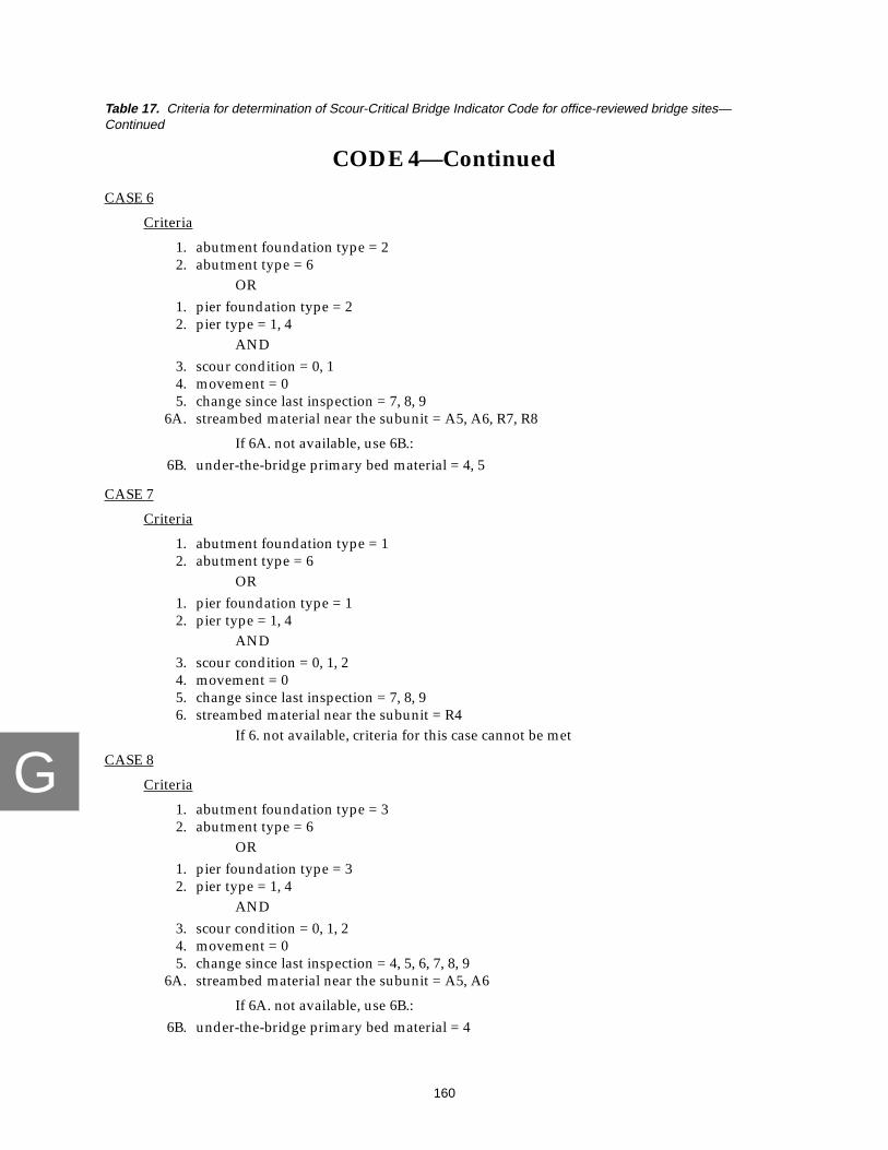
G
160
Table 17. Criteria for determination of Scour-Critical Bridge Indicator Code for office-reviewed bridge sites—Continued
CODE 4—Continued
CASE 6
Criteria
1. abutment foundation type = 22. abutment type = 6
OR1. pier foundation type = 22. pier type = 1, 4
AND3. scour condition = 0, 14. movement = 05. change since last inspection = 7, 8, 9
6A. streambed material near the subunit = A5, A6, R7, R8
If 6A. not available, use 6B.:6B. under-the-bridge primary bed material = 4, 5
CASE 7
Criteria
1. abutment foundation type = 12. abutment type = 6
OR1. pier foundation type = 12. pier type = 1, 4
AND3. scour condition = 0, 1, 24. movement = 05. change since last inspection = 7, 8, 96. streambed material near the subunit = R4
If 6. not available, criteria for this case cannot be met
CASE 8
Criteria
1. abutment foundation type = 32. abutment type = 6
OR1. pier foundation type = 32. pier type = 1, 4
AND3. scour condition = 0, 1, 24. movement = 05. change since last inspection = 4, 5, 6, 7, 8, 9
6A. streambed material near the subunit = A5, A6
If 6A. not available, use 6B.:6B. under-the-bridge primary bed material = 4

G
161
Table 17. Criteria for determination of Scour-Critical Bridge Indicator Code for office-reviewed bridge sites—Continued
CODE 4—Continued
CASE 9
Criteria
1. abutment foundation type = 32. abutment type = 6
OR1. pier foundation type = 32. pier type = 1, 4
AND3. scour condition = 0, 1, 24. movement = 05. change since last inspection = 7, 8, 96. streambed material near the subunit = A3, A4
If 6A. not available, use 6B.:6B. under-the-bridge primary bed material = 1, 2, 3, 7

G
162
Table 17. Criteria for determination of Scour-Critical Bridge Indicator Code for office-reviewed bridge sites—Continued
CODE 3
Code 3 indicates subunits in contact with streambed material consisting predominately oferodible, fine material.
CASE 1
Criteria
1. abutment foundation type = 22. abutment type = 2, 3, 4, 5
OR1. pier foundation type = 22. pier type = 3
AND3. scour condition = 0, 1, 24. movement = 05. change since last inspection = 4, 5, 6, 7, 8, 9
6A. streambed material near the subunit = A3, A4, R4
If 6A. not available, use 6B.:6B. under-the-bridge primary bed material = 1, 2, 3, 7
CASE 2
Criteria
1. abutment foundation type = 32. abutment type = 1, 2, 3, 4, 5, 7
OR1. pier foundation type = 32. pier type = 2, 3
AND3. scour condition = 0, 1, 2, 34. movement = 05. change since last inspection = 4, 5, 6, 7, 8, 9
6A. streambed material near the subunit = A3, A4
If 6A. not available, use 6B.:6B. under-the-bridge primary bed material = 1, 2, 3, 7
CASE 3
Criteria
1. abutment type = 92. scour condition = 13. movement = 04. change since last inspection = 4, 5, 6, 7, 8, 9

G
163
Table 17. Criteria for determination of Scour-Critical Bridge Indicator Code for office-reviewed bridge sites—Continued
CODE 3—Continued
CASE 4
Criteria
1. abutment foundation type = 22. abutment type = 6
OR1. pier foundation type = 22. pier type = 1, 4
AND3. scour condition = 0, 1, 24. movement = 05. change since last inspection = 4, 5, 6, 7, 8, 9
6A. streambed material near the subunit = A3, A4, A5, A6, R4
If 6A. not available, use 6B.:6B. under-the-bridge primary bed material = 1, 2, 3, 4, 7
CASE 5
Criteria
1. abutment foundation type = 12. abutment type = 6
OR1. pier foundation type = 12. pier type = 1, 4
AND3. scour condition = 0, 1, 24. movement = 05. change since last inspection = 4, 5, 6, 7, 8, 96. streambed material near the subunit = R4
If 6. not available, criteria for case cannot be met
CASE 6
Criteria
1. abutment foundation type = 12. abutment type = 1, 2, 3, 4, 5
OR1. pier foundation type = 12. pier type = 3
AND3. scour condition = 34. movement = 05. change since last inspection = 4, 5, 6, 7, 8, 9
Flag
For all criteria

G
164
Table 17. Criteria for determination of Scour-Critical Bridge Indicator Code for office-reviewed bridge sites—Continued
CODE 3—Continued
CASE 7
Criteria
1. abutment foundation type = 32. abutment type = 6
OR1. pier foundation type = 32. pier type = 1, 4
AND3. scour condition = 0, 1, 24. movement = 05. change since last inspection = 4, 5, 6, 7, 8, 9
6A. streambed material near the subunit = A3, A4
If 6A. not available, use 6B.:6B. under-the-bridge primary bed material = 1, 2, 3, 7

G
165
Table 17. Criteria for determination of Scour-Critical Bridge Indicator Code for office-reviewed bridge sites—Continued
CODE 2
Code 2 indicates subunits having critical site conditions related to scour, such as; movementof the subunit, significant change since last inspection, or scour condition for foundation that
potentially threatens bridge structure.
CASE 2
Criteria
1. movement = 1
CASE 3
Criteria
1. abutment foundation type = 22. abutment type = 2, 3, 4, 5
OR1. pier foundation type = 22. pier type = 3
AND3. scour condition = 3
CASE 4
Criteria
1. abutment type = 6OR
1. pier type = 1, 4AND
2. scour condition = 3
CASE 6
Criteria
1. change since last inspection = 3
Flag
For all criteria

167
H
APPENDIX HPROCEDURE FOR COMPUTATION OF THE SCOUR ASSESSMENT
RATING FOR FIELD-VIEWED BRIDGE SITES

H
168
PROCEDURE FOR COMPUTATION OF THE SCOUR ASSESSMENT RATING FOR FIELD-VIEWED BRIDGE SITES
The Scour Assessment Rating (Rating) rates or ranks the hydraulic threat of the stream to the bridge.The Rating is composed of individual component values for selected site conditions that are combined toprovide an overall Rating for the entire bridge structure. The Rating ranges from 0 to 100 where 0 indicatesa serious threat to the bridge and 100 indicates little or no threat to the bridge. Only subunits that meet thecriteria for scour assessments as outlined in this report are rated; for example, an expansive bridge thatcarries an elevated roadway will be rated based only on those subunits in contact with stream flow.
PennDOT BMS data are compared with data observed by USGS for subunit type and subunitfoundation type. The following flowcharts (figs. 32 and 33) and selection tables (tables 18-21) determinehow PennDOT and USGS data are used in the computation of the Scour Assessment Rating for field-viewed bridge sites on the worksheet presented in figure 34. When subunits cannot be rated because ofconflicting or unavailable data, they receive a rating of “999.” This rating serves only to indicate that noscore could be computed and does not imply any indication of bridge site or bridge structure stability.Because the individual subunits are components of the overall bridge structure, if an individual subunitreceives a rating of “999,” the entire structure cannot be rated and also receives a rating of “999.”
For cases where a foundation type of “not observed” is used in the computation of the Rating (asdetermined by the following flowchart and tables), the foundation type for that subunit is rated as iffounded on alluvium, which is a worst-case scenario. In reality, the foundation type may be more stableand PennDOT personnel will investigate these bridge sites and recompute the Rating and Code asinformation becomes available. Comments on the USGS data-collection form or in the BMS database mustbe consulted for additional information.
A field-viewed subunit can only be rated if data are complete for the following USGS data fields:
subunit typesubunit foundation typescour conditionevidence of movementwingwall condition, if presentcondition of countermeasures at subunitunder-bridge bed material
Rating an entire field-viewed bridge structure requires that all subunits that meet criteria for scourassessments are capable of being rated, as stated above, and that the following USGS data fields also arecomplete:
trapping potentialdebris potentialdebris horizontal and vertical locationevidence of pressure flow
When BMS data for foundation or type of a subunit are blank or indicated as “other” or, in somecases, when the BMS foundation type is not determined, the subunit is not rated and receives a “999” inthe database. PennDOT District personnel are instructed to revise the BMS data or check bridge recordsprior to rating by PennDOT personnel.

H
169
Pier type and pier foundation type data are stored in the PennDOT BMS database in items C39 andC40, respectively. These 2 PennDOT items contain 4 subfields each for PennDOT entry of pier information.The following assumptions must be made for use of BMS pier data in computing the Rating for bridges:
1. If only 1 set of pier data (1 subfield complete for pier type and 1 subfield completefor foundation type) is available, assume that these data apply to all piers for thebridge. For example; all piers of s bridge structure are of the same type with the samefoundation type, therefore, only one entry is made in the BMS database to describeall piers.
2. If the number of subfields of pier data equal the number of piers, assume that firstsubfield describes P01, the second subfield describes P02, and so on. For example; thevariation among piers of a specific bridge is substantial enough to warrantindividual entries for each pier.
3. If no data are available for piers or if data cannot be assigned to specific piersaccording to assumptions 1. and 2. above, the subunit cannot be rated and receives arating of “999.” For example; there are too many piers with too much variation inpier type and (or) foundation type to list each pier separately in the database sodescriptions of groups of piers are used in the BMS database. These groupdescriptions cannot be used for completion of the Rating and Code and the bridges,therefore, require manual computation by PennDOT personnel.
Several combinations of conflicting data are flagged to alert PennDOT reviewers that a morethorough review is required than for sites where USGS and PennDOT data are similar or compatible.The flag states that a special condition at this site requires PennDOT review. The combinations of data thatare flagged are:
1. USGS foundation type = bedrockBMS foundation type = L
2. USGS foundation type = piles/caissonsBMS foundation type = A, R
3. USGS foundation type = otherBMS foundation type = A, R, K, B-J, S, L
Several combinations of abutment types and abutment foundation types cannot occur in theconstruction of a bridge and these combinations are not rated (table 21). In these cases the subunit and thebridge structure receive a rating of “999” to indicate that no rating was computed and PennDOT Districtpersonnel are instructed to revise the BMS data or check bridge records prior to rating the bridge sitemanually.

H
170
Are BMS data for abutmenttype = blank or 9?
Select rating abutment type(use Table 18 for USGS abutment
type and BMS abutment type)
Are BMS data for abutmentfoundation type = blank or O?
Is USGS abutment foundation
Is BMS abutment foundationtype = P, X?
Select rating abutment foundationtype (use Table 20 for USGS
abutment foundation type and
type = not observed?
BMS abutment foundation type)
Figure 32. Computation of Scour Assessment Rating for abutments at field-viewed bridge sites.
YES
NO
NO
NO
NO
YES
YES
YES
assign
999subunitassign
999subunit
assign
999subunit
assign
999subunit

H
171
Are rating abutment type andrating abutment foundation type
combination in Table 21?
Are any data combinations
BedrockPiles/CaissonsOther
LA, RA, R, K, B-J, S, L
flagfinal
results(flag #1)
rating abutment type,rating abutment foundationtype and Criteria, computeScour Assessment Rating
YES
YES
NO
NO
USGS abutmentfoundation type
BMS abutmentfoundation type
for subunit as below?:
for subunit
Using
assign
999subunit
Figure 32. Computation of Scour Assessment Rating for abutments at field-viewed bridge sites—Continued.

H
172
Are BMS data forpier type blank?
(all C39 fields = blank)
Are BMS data forpier foundation type blank?
(all C40 fields = blank)
Can BMS data fortype be assigned to
pier according to rules?
Can BMS data for pierfoundation type be assigned to
pier according to rules?
Is BMS pier type = 9?
Select rating pier type(use Table 19 for USGS
pier type and BMS pier type)
Is BMS pier foundation
YES
YES
NO
YES
YES
NO
NO
YES
NO
YES
NO
NO
assign
999
Figure 33. Computation of Scour Assessment Rating for piers at field-viewed bridge sites.
type = O?
Assign BMS pier type tosubunit according to rules
Assign BMS pier foundationtype to subunit according
to rules
subunit
assign
999subunit
assign
999subunit
assign
999subunit
assign
999subunit
assign
999subunit

H
173
flag
Is USGS pier foundation
Are any data combinations for
YES
YES
YES
Is BMS pier foundationtype = P, X?
Select rating pier foundation
USGS pier
BedrockPiles/CaissonsOther
LA, RA, R, K, B-J, S, L
finalresults
(flag #1)
type = not observed?
foundation type
type (use Table 20 forUSGS foundation type
and BMS foundation type)
rating pier type,rating pier foundation typeand Criteria, compute Scour
Assessment Rating
NO
NO
NO
NO
BMS pierfoundation type
subunit as below?:
NO
for subunit
Using
assign
999subunit
Figure 33. Computation of Scour Assessment Rating for piers at field-viewed bridge sites—Continued.

H
174
Table 18. Selection of abutment type used in the Scour Assessment Rating for field-viewed bridge sites[w/o, without; 999 indicates that no choice of abutment type is necessary, subunit cannot be rated]
USGS Type →1 2 3 4 5 6 7 8 9 10
BMS Type ↓
1 stub (1) cantilever (2) gravity concrete (3) spill-through (4) unknownconcrete (5)
stone masonry (6) piles/bents (7) concrete w/opiles/bents (8)
mechanicallystabilizedearth (9)
stub (1)
2 stub (1) cantilever (2) gravity concrete (3) spill-through (4) unknownconcrete (5)
stone masonry (6) piles/bents (7) concrete w/opiles/bents (8)
mechanicallystabilizedearth (9)
cantilever (2)
3 stub (1) cantilever (2) gravity concrete (3) spill-through (4) unknownconcrete (5)
stone masonry (6) piles/bents (7) concrete w/opiles/bents (8)
mechanicallystabilizedearth (9)
gravity concrete (3)
4 stub (1) cantilever (2) gravity concrete (3) spill-through (4) unknownconcrete (5)
stone masonry (6) piles/bents (7) concrete w/opiles/bents (8)
mechanicallystabilizedearth (9)
stone masonry (6)
5 stub (1) cantilever (2) gravity concrete (3) spill-through (4) unknownconcrete (5)
stone masonry (6) piles/bents (7) concrete w/opiles/bents (8)
mechanicallystabilizedearth (9)
gravity concrete (3)
6 stub (1) cantilever (2) gravity concrete (3) spill-through (4) unknownconcrete (5)
stone masonry (6) piles/bents (7) concrete w/opiles/bents (8)
mechanicallystabilizedearth (9)
stub (1)
7 stub (1) cantilever (2) gravity concrete (3) spill-through (4) unknownconcrete (5)
stone masonry (6) piles/bents (7) concrete w/opiles/bents (8)
mechanicallystabilizedearth (9)
mechanicallystabilizedearth (9)
8 stub (1) cantilever (2) gravity concrete (3) spill-through (4) unknownconcrete (5)
stone masonry (6) piles/bents (7) concrete w/opiles/bents (8)
mechanicallystabilizedearth (9)
spill-through (4)
9 999 999 999 999 999 999 999 999 999 999
A stub (1) cantilever (2) gravity concrete (3) spill-through (4) unknownconcrete (5)
stone masonry (6) piles/bents (7) concrete w/opiles/bents (8)
mechanicallystabilizedearth (9)
mechanicallystabilizedearth (9)
B stub (1) cantilever (2) gravity concrete (3) spill-through (4) unknownconcrete (5)
stone masonry (6) piles/bents (7) concrete w/opiles/bents (8)
mechanicallystabilizedearth (9)
mechanicallystabilizedearth (9)
C stub (1) cantilever (2) gravity concrete (3) spill-through (4) unknownconcrete (5)
stone masonry (6) piles/bents (7) concrete w/opiles/bents (8)
mechanicallystabilizedearth (9)
mechanicallystabilizedearth (9)
D stub (1) cantilever (2) gravity concrete (3) spill-through (4) unknownconcrete (5)
stone masonry (6) piles/bents (7) concrete w/opiles/bents (8)
mechanicallystabilizedearth (9)
other (10)

H
175
E stub (1) cantilever (2) gravity concrete (3) spill-through (4) unknownconcrete (5)
stone masonry (6) piles/bents (7) concrete w/opiles/bents (8)
mechanicallystabilizedearth (9)
piles/bents (7)
F stub (1) cantilever (2) gravity concrete (3) spill-through (4) unknownconcrete (5)
stone masonry (6) piles/bents (7) concrete w/opiles/bents (8)
mechanicallystabilizedearth (9)
other (10)
G stub (1) cantilever (2) gravity concrete (3) spill-through (4) unknownconcrete (5)
stone masonry (6) piles/bents (7) concrete w/o piles/bents (8)
mechanicallystabilizedearth (9)
stone masonry (6)
H stub (1) cantilever (2) gravity concrete (3) spill-through (4) unknownconcrete (5)
stone masonry (6) piles/bents (7) concrete w/o piles/bents (8)
mechanicallystabilizedearth (9)
mechanicallystabilizedearth (9)
I stub (1) cantilever (2) gravity concrete (3) spill-through (4) unknownconcrete (5)
stone masonry (6) piles/bents (7) concrete w/o piles/bents (8)
mechanicallystabilizedearth (9)
mechanicallystabilizedearth (9)
J stub (1) cantilever (2) gravity concrete (3) spill-through (4) unknownconcrete (5)
stone masonry (6) piles/bents (7) concrete w/o piles/bents (8)
mechanicallystabilizedearth (9)
mechanicallystabilizedearth (9)
K stub (1) cantilever (2) gravity concrete (3) spill-through (4) unknownconcrete (5)
stone masonry (6) piles/bents (7) concrete w/o piles/bents (8)
mechanicallystabilizedearth (9)
other (10)
L stub (1) cantilever (2) gravity concrete (3) spill-through (4) unknownconcrete (5)
stone masonry (6) piles/bents (7) concrete w/o piles/bents (8)
mechanicallystabilizedearth (9)
other (10)
X stub (1) cantilever (2) gravity concrete (3) spill-through (4) unknownconcrete (5)
stone masonry (6) piles/bents (7) concrete w/o piles/bents (8)
mechanicallystabilizedearth (9)
unknownconcrete (5)
Y stub (1) cantilever (2) gravity concrete (3) spill-through (4) unknownconcrete (5)
stone masonry (6) piles/bents (7) concrete w/o piles/bents (8)
mechanicallystabilizedearth (9)
spill-through (4)
Z stub (1) cantilever (2) gravity concrete (3) spill-through (4) unknownconcrete (5)
stone masonry (6) piles/bents (7) concrete w/o piles/bents (8)
mechanicallystabilizedearth (9)
mechanicallystabilizedearth (9)
blank 999 999 999 999 999 999 999 999 999 999
Table 18. Selection of abutment type used in the Scour Assessment Rating for field-viewed bridge sites—Continued[w/o, without; 999 indicates that no choice of abutment type is necessary, subunit cannot be rated]
USGS Type →1 2 3 4 5 6 7 8 9 10
BMS Type ↓

H
176
Table 19. Selection of pier type used in the Scour Assessment Rating for field-viewed bridge sites[999 indicates that no choice of abutment type is necessary, subunit cannot be rated]
USGS Type →1 2 3 4 5
BMS Type ↓
1 timber (1) steel (2) concrete (3) stone masonry (4) timber (1)2 timber (1) steel (2) concrete (3) stone masonry (4) steel (2)3 timber (1) steel (2) concrete (3) stone masonry (4) concrete (3)4 timber (1) steel (2) concrete (3) stone masonry (4) concrete (3)5 timber (1) steel (2) concrete (3) stone masonry (4) concrete (3)6 timber (1) steel (2) concrete (3) stone masonry (4) stone masonry (4)7 timber (1) steel (2) concrete (3) stone masonry (4) concrete (3)9 timber (1) steel (2) concrete (3) stone masonry (4) other (5)
Blank 999 999 999 999 999
Table 20. Selection of abutment and pier foundation type used in the Scour Assessment Rating forfield-viewed bridge sites[999 indicates that no choice of abutment type is necessary, subunit cannot be rated]
USGS foundationtype →
1 2 3 4 5BMS foundation
type ↓
A bedrock (1) bedrock (1) piles/caissons (3) bedrock (1) bedrock (1)B-J piles/caissons (3) piles/caissons (3) piles/caissons (3) piles/caissons (3) piles/caissons (3)K alluvium (2) alluvium (2) piles/caissons (3) alluvium (2) alluvium (2)L bedrock (1) alluvium (2) piles/caissons (3) alluvium (2) alluvium (2)
O / blank 999 999 999 999 999P 999 999 999 999 not observed (5)R bedrock (1) bedrock (1) piles/caissons (3) bedrock (1) bedrock (1)S piles/caissons (3) piles/caissons (3) piles/caissons (3) piles/caissons (3) piles/caissons (3)X 999 999 999 999 not observed (5)
Table 21. Incompatible combinations of abutment types and foundationtypes in the Scour Assessment Rating for field-viewed bridge sites[w/o, without]
Abutment type Abutment foundation type
Stub (1) Alluvium (2)Stub (1) Not observed (5)Piles/bents (7) Bedrock (1)Concrete w/o piles/bents (8) Piles/caissons (3)

H
177
Figure 34. Worksheet for computation of Scour Assessment Rating for field-viewed bridge sites.
Use the rating abutment type, rating abutment foundation type, rating pier type, and rating pierfoundation type determined above in the worksheet that follows. All other required site data are gatheredfrom the field-viewed bridge site data-collection form.

H
178
Figure 34. Worksheet for computation of Scour Assessment Rating for field-viewed bridge sites—Continued.
Bridge ID: ______________________________
I. ABUTMENTS NEAR FAR
A. Scour condition at abutments:1. Movement
a. Foundation type:1) Alluvium, not observed
a) Abutment type:
(1) Piles/bents, spill-through (-75) _____ _____
(2) Cantilever, gravity, unknown concrete,concrete without piles/bents (-75) _____ _____
(3) Stone masonry, mechanically stabilized, other (-90) _____ _____
2) Piles/caissonsa) Abutment type:
(1) Piles/bents, stub, spill-through (-75) _____ _____
(2) Cantilever, gravity, unknown concrete (-75) _____ _____
(3) Stone masonry, mechanically stabilized, other (-80) _____ _____
3) Bedrocka) Abutment type:
(1) Cantilever, gravity, spill-through,unknown concrete, stub (-75) _____ _____
(2) Stone masonry, concrete without piles/bentsmechanically stabilized, other (-75) _____ _____
2. Serious scoura. Foundation type:
1) Alluvium, not observeda) Abutment type:
(1) Piles/bents, spill-through (-40) _____ _____
(2) Cantilever, gravity, unknown concrete,concrete without piles/bents (-60) _____ _____
(3) Stone masonry, mechanically stabilized, other (-85) _____ _____
2) Piles/caissonsa) Abutment type:
(1) Piles/bents, stub, spill-through (-40) _____ _____
(2) Cantilever, gravity, unknown concrete (-50) _____ _____
(3) Stone masonry, mechanically stabilized, other (-75) _____ _____
Overall Score: ________________

H
179
Figure 34. Worksheet for computation of Scour Assessment Rating for field-viewed bridge sites—Continued.
I. ABUTMENTS—Continued NEAR FARA. Scour condition at abutments:—Continued
2. Serious scour—Continueda. Foundation type:—Continued
3) Bedrocka) Abutment type:
(1) Cantilever, gravity, spill-through, unknownconcrete, stub (-60) _____ _____
(2) Stone masonry, concrete without piles/bents,mechanically stabilized, other (-75) _____ _____
3. Advanced scoura. Wingwall condition = good or wingwall not necessary
1) Foundation type:a) Alluvium, not observed
(1) Abutment type:(a) Piles/bents, spill-through (-20) _____ _____(b) Cantilever, gravity, unknown concrete, concrete
without piles/bents (-40) _____ _____(c) Stone masonry, mechanically stabilized, other (-70) _____ _____
b) Piles/caissons(1) Abutment type:
(a) Piles/bents, stub, spill-through (-20) _____ _____(b) Cantilever, gravity, unknown concrete (-20) _____ _____(c) Stone masonry, mechanically stabilized, other (-50) _____ _____
c) Bedrock(1) Abutment type:
(a) Cantilever, gravity, spill-through, unknownconcrete, stub (-10) _____ _____
(b) Stone masonry, concrete without piles/bents,mechanically stabilized, other (-15) _____ _____
b. Wingwall condition = partial or no wingwall but one is needed1) Foundation type:
a) Alluvium, not observed(1) Abutment type:
(a) Piles/bents, spill-through (-40) _____ _____(b) Cantilever, gravity, unknown concrete, concrete
without piles/bents (-50) _____ _____(c) Stone masonry, mechanically stabilized, other (-75) _____ _____

H
180
Figure 34. Worksheet for computation of Scour Assessment Rating for field-viewed bridge sites—Continued.
I. ABUTMENTS—Continued NEAR FARA. Scour condition at abutments:—Continued
3. Advanced scour—Continuedb. Wingwall condition = partial or no wingwall but one is needed—Continued
1) Foundation type:—Continuedb) Piles/caissons
(1) Abutment type:(a) Piles/bents, stub, spill-through (-40) _____ _____(b) Cantilever, gravity, unknown concrete (-40) _____ _____(c) Stone masonry, mechanically stabilized, other (-60) _____ _____
c) Bedrock(1) Abutment type:
(a) Cantilever, gravity, spill-through, unknownconcrete, stub (-30) _____ _____
(b) Stone masonry, concrete without pile/bentsmechanically stabilized, other (-35) _____ _____
c. Wingwall condition = failed1) Foundation type:
a) Alluvium, not observed(1) Abutment type:
(a) Piles/bents, spill-through (-55) _____ _____(b) Cantilever, gravity, unknown concrete, concrete
without piles/bents (-65) _____ _____(c) Stone masonry, mechanically stabilized, other (-80) _____ _____
b) Piles/caissons(1) Abutment type:
(a) Piles/bents, stub, spill-through (-55) _____ _____(b) Cantilever, gravity, unknown concrete (-55) _____ _____(c) Stone masonry, mechanically stabilized, other (-70) _____ _____
c) Bedrock(1) Abutment type:
(a) Cantilever, gravity, spill-through, unknownconcrete, stub (-50) _____ _____
(b) Stone masonry, concrete without pile/bentsmechanically stabilized, other (-55) _____ _____

H
181
Figure 34. Worksheet for computation of Scour Assessment Rating for field-viewed bridge sites—Continued.
I. ABUTMENTS—Continued NEAR FARA. Scour condition at abutments:—Continued
4. Minor scoura. Wingwall condition = good or wingwall not necessary
1) Foundation type:a) Alluvium, not observed
(1) Abutment type:(a) Piles/bents, spill-through (-5) _____ _____(b) Cantilever, gravity, unknown concrete, concrete
without piles/bents (-15) _____ _____(c) Stone masonry, mechanically stabilized, other (-35) _____ _____
b) Piles/caissons(1) Abutment type:
(a) Piles/bents, stub, spill-through (-5) _____ _____(b) Cantilever, gravity, unknown concrete (-10) _____ _____(c) Stone masonry, mechanically stabilized, other (-30) _____ _____
c) Bedrock(1) Abutment type:
(a) Cantilever, gravity, spill-through, unknownconcrete, stub (0) _____ _____
(b) Stone masonry, concrete without piles/bentsmechanically stabilized, other (-5) _____ _____
b. Wingwall condition = partial or no wingwall but one is needed1) Foundation type:
a) Alluvium, not observed(1) Abutment type:
(a) Piles/bents, spill-through (-30) _____ _____(b) Cantilever, gravity, unknown concrete, concrete
without piles/bents (-40) _____ _____(c) Stone masonry, mechanically stabilized, other (-55) _____ _____
b) Piles/caissons(1) Abutment type:
(a) Piles/bents, stub, spill-through (-30) _____ _____(b) Cantilever, gravity, unknown concrete (-35) _____ _____(c) Stone masonry, mechanically stabilized, other (-50) _____ _____
c) Bedrock(1) Abutment type:
(a) Cantilever, gravity, spill-through, unknownconcrete, stub (-25) _____ _____
(b) Stone masonry, concrete without piles/bents,mechanically stabilized, other (-30) _____ _____

H
182
Figure 34. Worksheet for computation of Scour Assessment Rating for field-viewed bridge sites—Continued.
I. ABUTMENTS—Continued NEAR FARA. Scour condition at abutments:—Continued
4. Minor scour—Continuedc. Wingwall condition = failed
1) Foundation type:a) Alluvium, not observed
(1) Abutment type:(a) Piles/bents, spill-through (-40) _____ _____(b) Cantilever, gravity, unknown concrete, concrete
without pile/bents (-60) _____ _____(c) Stone masonry, mechanically stabilized, other (-65) _____ _____
b) Piles/caissons(1) Abutment type:
(a) Piles/bents, stub, spill-through (-40) _____ _____(b) Cantilever, gravity, unknown concrete (-45) _____ _____(c) Stone masonry, mechanically stabilized, other (-60) _____ _____
c) Bedrock(1) Abutment type:
(a) Cantilever, gravity, spill-through, unknownconcrete, stub (-30) _____ _____
(b) Stone masonry, concrete without pile/bents,mechanically stabilized, other (-35) _____ _____
5. No scoura. Wingwall condition = good or wingwall not necessary
1) Foundation type:a) Alluvium, not observed
(1) Abutment type:(a) Piles/bents, spill-through (-5) _____ _____(b) Cantilever, gravity, unknown concrete, concrete
without piles/bents (-10) _____ _____(c) Stone masonry, mechanically stabilized, other (-25) _____ _____
b) Piles/caissons(1) Abutment type:
(a) Piles/bents, stub, spill-through (-5) _____ _____(b) Cantilever, gravity, unknown concrete (-5) _____ _____(c) Stone masonry, mechanically stabilized, other (-20) _____ _____
c) Bedrock(1) Abutment type:
(a) Cantilever, gravity, spill-through, unknownconcrete, stub (0) _____ _____
(b) Stone masonry, concrete without piles/bentsmechanically stabilized, other (-5) _____ _____

H
183
Figure 34. Worksheet for computation of Scour Assessment Rating for field-viewed bridge sites—Continued.
I. ABUTMENTS—Continued NEAR FARA. Scour condition at abutments:—Continued
5. No scour—Continuedb. Wingwall condition = partial or no wingwall but one is needed
1) Foundation type:a) Alluvium, not observed
(1) Abutment type:(a) Piles/bents, spill-through (-25) _____ _____(b) Cantilever, gravity, unknown concrete, concrete
without piles/bents (-35) _____ _____(c) Stone masonry, mechanically stabilized, other (-45) _____ _____
b) Piles/caissons(1) Abutment type:
(a) Piles/bents, stub, spill-through (-25) _____ _____(b) Cantilever, gravity, unknown concrete (-35) _____ _____(c) Stone masonry, mechanically stabilized, other (-45) _____ _____
c) Bedrock(1) Abutment type:
(a) Cantilever, gravity, spill-through, unknownconcrete, stub (-20) _____ _____
(b) Stone masonry, concrete without piles/bents,mechanically stabilized, other (-25) _____ _____
c. Wingwall condition = Failed
1) Foundation type:a) Alluvium, not observed
(1) Abutment type:(a) Piles/bents, spill-through (-35) _____ _____(b) Cantilever, gravity, unknown concrete, concrete
without piles/bents (-50) _____ _____(c) Stone masonry, mechanically stabilized, other (-60) _____ _____
b) Piles/caissons(1) Abutment type:
(a) Piles/bents, stub, spill-through (-35) _____ _____(b) Cantilever, gravity, unknown concrete (-40) _____ _____(c) Stone masonry, mechanically stabilized, other (-55) _____ _____
c) Bedrock(1) Abutment type:
(a) Cantilever, gravity, spill-through, unknownconcrete, stub (-25) _____ _____
(b) Stone masonry, concrete without piles/bents,mechanically stabilized, other (-30) _____ _____

H
184
Figure 34. Worksheet for computation of Scour Assessment Rating for field-viewed bridge sites—Continued.
I. ABUTMENTS—Continued NEAR FARB. Has every countermeasure, located at an abutment, received a
condition rating of Good?NOTE:--Under-bridge bed material = 6 (concrete/steel) is a good countermeasure--If no countermeasures at the subunit, answer NO
1. Yes (+10) _____ _____2. No (0) _____ _____
ABUTMENT SUBSCORES _____ _____II. PIERS P01 P02 P03 P04
A. Scour condition at piers1. Movement:
a. Pier foundation type:1) Alluvium, not observed
a) Pier type:(1) Steel, concrete (-85) _____ _____ _____ _____(2) Timber, stone masonry, other (-85) _____ _____ _____ _____
2) Piles/caissonsa) Pier type:
(1) Steel, concrete (-85) _____ _____ _____ _____(2) Timber, stone masonry, other (-85) _____ _____ _____ _____
3) Bedrocka) Pier type:
(1) Steel, concrete (-80) _____ _____ _____ _____(2) Timber, stone masonry, other (-85) _____ _____ _____ _____
2. Serious scoura. Pier foundation type:
1) Alluvium, not observeda) Pier type:
(1) Steel, concrete (-70) _____ _____ _____ _____(2) Timber, stone masonry, other (-85) _____ _____ _____ _____
2) Piles/caissonsa) Pier type:
(1) Steel, concrete (-65) _____ _____ _____ _____(2) Timber, stone masonry, other (-75) _____ _____ _____ _____
3) Bedrocka) Pier type:
(1) Steel, concrete (-65) _____ _____ _____ _____(2) Timber, stone masonry, other (-75) _____ _____ _____ _____
3. Advanced scoura. Pier foundation type:
1) Alluvium, not observeda) Pier type:
(1) Steel, concrete (-50) _____ _____ _____ _____(2) Timber, stone masonry, other (-70) _____ _____ _____ _____

H
185
Figure 34. Worksheet for computation of Scour Assessment Rating for field-viewed bridge sites—Continued.
II. PIERS—Continued P01 P02 P03 P04A. Scour condition at piers—Continued
3. Advanced scour—Continueda. Pier foundation type:—Continued
2) Piles/caissonsa) Pier type:
(1) Steel, concrete (-25) _____ _____ _____ _____(2) Timber, stone masonry, other (-50) _____ _____ _____ _____
3) Bedrocka) Pier type:
(1) Steel, concrete (-15) _____ _____ _____ _____(2) Timber, stone masonry, other (-20) _____ _____ _____ _____
4. Minor scoura. Pier foundation type:
1) Alluvium, not observeda) Pier type:
(1) Steel, concrete (-20) _____ _____ _____ _____(2) Timber, stone masonry, other (-30) _____ _____ _____ _____
2) Piles/caissonsa) Pier type:
(1) Steel, concrete (-10) _____ _____ _____ _____(2) Timber, stone masonry, other (-20) _____ _____ _____ _____
3) Bedrocka) Pier type:
(1) Steel, concrete (0) _____ _____ _____ _____(2) Timber, stone masonry, other (0) _____ _____ _____ _____
5. No scoura. Pier foundation type:
1) Alluvium, not observeda) Pier type:
(1) Steel, concrete (-10) _____ _____ _____ _____(2) Timber, stone masonry, other (-15) _____ _____ _____ _____
2) Piles/caissonsa) Pier type:
(1) Steel, concrete (-5) _____ _____ _____ _____(2) Timber, stone masonry, other (-10) _____ _____ _____ _____
3) Bedrocka) Pier type:
(1) Steel, concrete (0) _____ _____ _____ _____(2) Timber, stone masonry, other (-5) _____ _____ _____ _____

H
186
Figure 34. Worksheet for computation of Scour Assessment Rating for field-viewed bridge sites—Continued.
II. PIERS—Continued P01 P02 P03 P04B. Has every countermeasure, located at a pier, received a
condition rating of Good?
NOTE:
--Under-bridge bed material = 6 (concrete/steel) is a good countermeasure
--If no countermeasures at the subunit, answer NO
1. Yes (+10) _____ _____ _____ _____
2. No (0) _____ _____ _____ _____
PIER SUBSCORES _____ _____ _____ _____
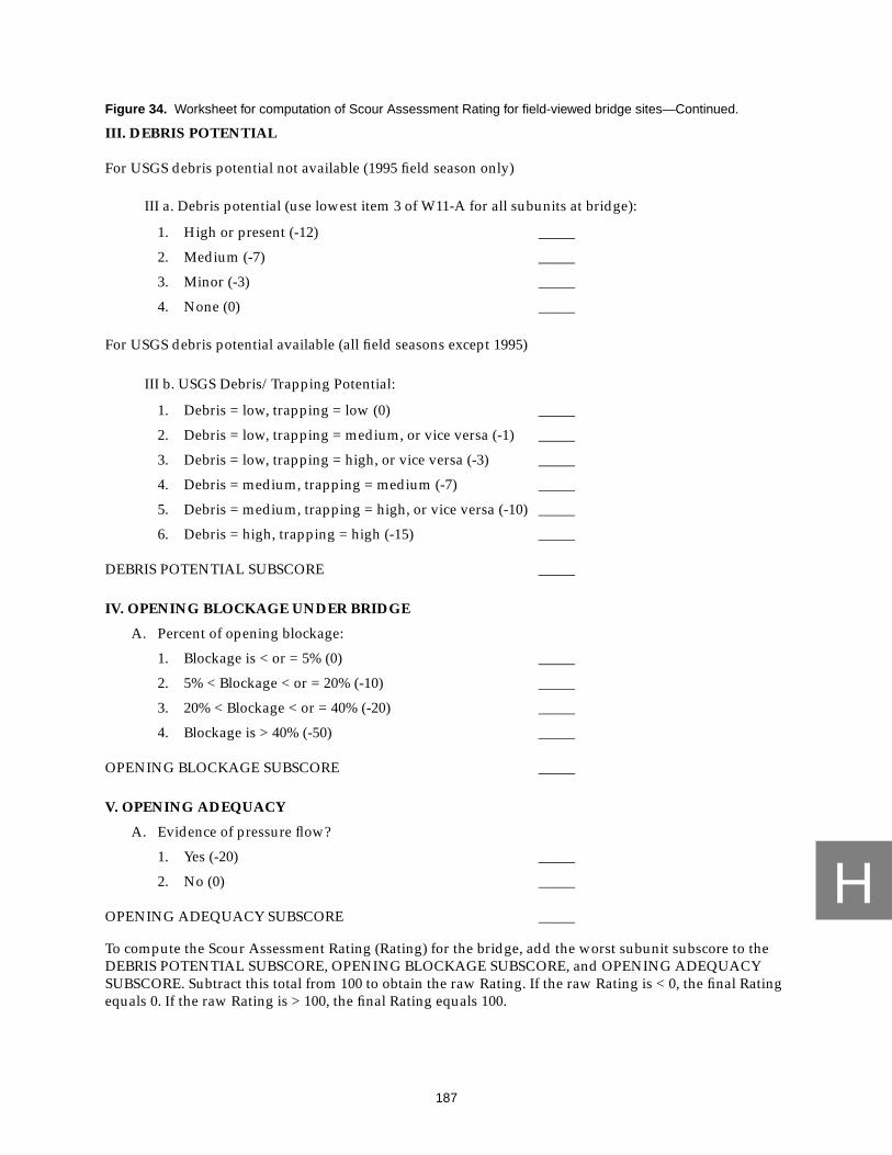
H
187
Figure 34. Worksheet for computation of Scour Assessment Rating for field-viewed bridge sites—Continued.
III. DEBRIS POTENTIAL
For USGS debris potential not available (1995 field season only)
III a. Debris potential (use lowest item 3 of W11-A for all subunits at bridge):
1. High or present (-12) _____
2. Medium (-7) _____
3. Minor (-3) _____
4. None (0) _____
For USGS debris potential available (all field seasons except 1995)
III b. USGS Debris/Trapping Potential:
1. Debris = low, trapping = low (0) _____
2. Debris = low, trapping = medium, or vice versa (-1) _____
3. Debris = low, trapping = high, or vice versa (-3) _____
4. Debris = medium, trapping = medium (-7) _____
5. Debris = medium, trapping = high, or vice versa (-10) _____
6. Debris = high, trapping = high (-15) _____
DEBRIS POTENTIAL SUBSCORE _____
IV. OPENING BLOCKAGE UNDER BRIDGE
A. Percent of opening blockage:
1. Blockage is < or = 5% (0) _____
2. 5% < Blockage < or = 20% (-10) _____
3. 20% < Blockage < or = 40% (-20) _____
4. Blockage is > 40% (-50) _____
OPENING BLOCKAGE SUBSCORE _____
V. OPENING ADEQUACY
A. Evidence of pressure flow?
1. Yes (-20) _____
2. No (0) _____
OPENING ADEQUACY SUBSCORE _____
To compute the Scour Assessment Rating (Rating) for the bridge, add the worst subunit subscore to theDEBRIS POTENTIAL SUBSCORE, OPENING BLOCKAGE SUBSCORE, and OPENING ADEQUACYSUBSCORE. Subtract this total from 100 to obtain the raw Rating. If the raw Rating is < 0, the final Ratingequals 0. If the raw Rating is > 100, the final Rating equals 100.

H
188
Figure 34. Worksheet for computation of Scour Assessment Rating for field-viewed bridge sites—Continued.
The following site conditions are considered important in evaluating the scour vulnerability of abridge site; however, they are not used in computation of the Rating
(Check appropriate boxes)
I. ABUTMENTS NEAR FAR
A. Opening type:1. Hardened, trapezoid _____ _____2. Unhardened, trapezoid _____ _____3. Rectangular, arched, other
a. Set back from bank?1) Yes _____ _____2) No _____ _____
B. Abutment attack angle:1. > 45 degrees _____ _____2. 31 - 45 degrees _____ _____3. 16 - 30 degrees _____ _____4. 0 - 15 degrees _____ _____
C. Change in abutment since last inspection:1. Significant change that could affect substructure _____ _____2. Some change but poses no threat to structure _____ _____3. No significant change _____ _____4. No change _____ _____
D. Is a blow hole present?1. Yes _____ _____2. No _____ _____
II. PIERS P01 P02 P03 P04A. Pier attack angle:
1. > 45 degrees _____ _____ _____ _____
2. 31 - 45 degrees _____ _____ _____ _____
3. 16 -30 degrees _____ _____ _____ _____
4. 0 - 15 degrees _____ _____ _____ _____
B. Ratio of debris width to pier width:
1. Ratio > 3 _____ _____ _____ _____
2. Ratio = 3 _____ _____ _____ _____
3. Ratio = 2 _____ _____ _____ _____
4. Ratio = 1 _____ _____ _____ _____
5. No debris _____ _____ _____ _____

H
189
Figure 34. Worksheet for computation of Scour Assessment Rating for field-viewed bridge sites—Continued.
II. PIERS—Continued P01 P02 P03 P04C. Shape of pier nose:
1. H-beam columns, square _____ _____ _____ _____
2. Cylindrical columns, cylinder, round _____ _____ _____ _____
3. Pointed _____ _____ _____ _____
D. Pier location:
1. Mid-channel _____ _____ _____ _____
2. On bank _____ _____ _____ _____
3. Over bank _____ _____ _____ _____
E. Change in pier since last inspection
1. Significant change, could affect substructure _____ _____ _____ _____
2. Some change but poses no threat _____ _____ _____ _____
3. No significant change _____ _____ _____ _____
4. No change _____ _____ _____ _____
III. CHANNEL
A. Scour hole not in contact with substructure?
1. Yes _____
2. No _____
B. Stream slope:
1. High _____
2. Medium _____
3. Low _____
C. Underbridge bed material:
1. Silt/clay, sand _____
2. Gravel _____
3. Cobble/ boulder _____
4. Bedrock, concrete, steel _____
D. Failed or possible scour hole backfill or rock protection?
1. Upstream _____
2. Downstream _____
3. No _____

H
190
Figure 34. Worksheet for computation of Scour Assessment Rating for field-viewed bridge sites—Continued.
IV. BANKS LEFT RIGHT
A. Upstream bank material:1. Silt/clay, sand _____ _____2. Gravel _____ _____3. Cobble/boulder _____ _____4. Bedrock, concrete, steel _____ _____
B. Vegetative cover:1. 0% - 25% _____ _____2. 26% - 50% _____ _____3. 51% - 75% _____ _____4. 76% - 100% _____ _____
C. Bank erosion:1. Mass wasting _____ _____2. Heavy fluvial erosion _____ _____3. Light fluvial erosion _____ _____4. None _____ _____
D. Cutbank:1. < or = 1B _____ _____2. 1B < cutbank < 2B _____ _____3. > 2B or none _____ _____
E. Meander impact:1. < or = 1B _____ _____2. 1B < meander impact < 2B _____ _____3. > 2B or none _____ _____
V. OPENING ADEQUACY
A. Is opening adequacy rated good?
1. Yes _____
2. No _____
VI. ROADWAY OVERTOPPING
A. Evidence of roadway overtopping?
1. Yes _____
2. No _____
VII. ROADWAY APPROACH
A. Is approach roadway subject to meander impact/cutbank?
1. Yes _____
2. No _____

191
I
APPENDIX IPROCEDURE FOR COMPUTATION OF THE SCOUR ASSESSMENT
RATING FOR OFFICE-REVIEWED BRIDGE SITES

I
192
PROCEDURE FOR COMPUTATION OF THE SCOUR ASSESSMENT RATING
FOR OFFICE-REVIEWED BRIDGE SITES
The Scour Assessment Rating (Rating) for office-reviewed bridge sites serves the same purpose asthat for field-viewed bridge sites. The office-reviewed Rating is composed of component values forindividual bridge subunits and selected site conditions that are combined to provide an overall bridgestructure rating similar to the field-viewed Rating. Only subunits that meet the criteria for scourassessments as outlined in this report are rated; for example, an expansive bridge that carries an elevatedroadway will be rated on only those subunits in contact with stream flow.
An office-reviewed subunit can only be rated if PennDOT data are complete for the following datafields:
subunit typesubunit foundation typescour conditionevidence of movementwingwall condition, if presentcondition of countermeasures at subunitunder-bridge bed material
Rating an entire office-reviewed bridge structure requires that all subunits that meet criteria forscour assessments are capable of being rated and that the following PennDOT data fields are complete:
trapping potentialdebris potentialevidence of pressure flow
When subunits cannot be rated, they receive a rating of “999.” Because individual subunits arecomponents of the overall bridge structure, if a subunit of the bridge is rated “999,” then the entirestructure cannot be rated and also receives a rating of “999.” When existing PennDOT data for foundationor type of a subunit are indicated as “other” or “not determined,” the subunit cannot be rated and receivesa rating “999.” PennDOT District personnel are instructed to revise the BMS data or check bridge recordsprior to PennDOT personnel subsequently rating the bridge structure manually. If possible, discrepanciesbetween existing PennDOT data, (for example, plans, hydrologic and hydraulic reports, and(or)foundation reports) and BMS data must be resolved at the time of the office review, or the bridge cannot berated. Abutment type, pier type, and subunit foundation type are determined in a manner similar to thatof field-viewed bridges with the prescribed flowcharts (figs. 35 and 36) and tables (tables 22-24).The worksheet presented in figure 37 is then used to determine the Rating of each substructure unit andthe overall bridge structure.

I
193
Based on existing PennDOT data,assign abutment type from table 22
Can abutment type be assigned?
Based on existing PennDOT data,assign abutment foundation typefrom table 24.
Can abutment foundation
Compute Rating using abutment type andabutment foundation type with the followingworksheet (fig. 37).
assignNO
NO
YES
subunit999
assignsubunit
999
Figure 35. computation of Scour Assessment Rating for abutments at office-reviewed bridge sites.
type be assigned?
YES

I
194
Based on existing PennDOT data,assign pier type from table 23.
Can pier type be assigned?
Based on existing PennDOT data,assign pier foundation typefrom table 24.
Can pier foundation type
Compute Rating using pier type andpier foundation type with the followingworksheet (fig. 37).
assignNO
NO
YES
YES
subunit999
assignsubunit
999
Figure 36. computation of Scour Assessment Rating for piers at office-reviewed bridge sites.
be assigned?
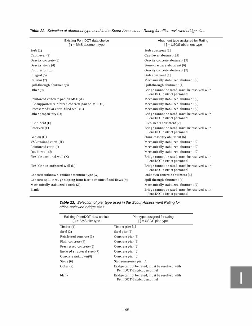
I
195
Table 22. Selection of abutment type used in the Scour Assessment Rating for office-reviewed bridge sites
Existing PennDOT data choice( ) = BMS abutment type
Abutment type assigned for Rating[ ] = USGS abutment type
Stub (1) Stub abutment [1]Cantilever (2) Cantilever abutment [2]Gravity concrete (3) Gravity concrete abutment [3]Gravity stone (4) Stone-masonry abutment [6]Counterfort (5) Gravity concrete abutment [3]Integral (6) Stub abutment [1]Cellular (7) Mechanically stabilized abutment [9]Spill-through abutment(8) Spill-through abutment [4]Other (9) Bridge cannot be rated, must be resolved with
PennDOT district personnelReinforced concrete pad on MSE (A) Mechanically stabilized abutment [9]Pile supported reinforced concrete pad on MSE (B) Mechanically stabilized abutment [9]Precast modular earth-filled wall (C) Mechanically stabilized abutment [9]Other proprietary (D) Bridge cannot be rated, must be resolved with
PennDOT district personnelPile / bent (E) Piles/bents abutment [7]Reserved (F) Bridge cannot be rated, must be resolved with
PennDOT district personnelGabion (G) Stone-masonry abutment [6]VSL retained earth (H) Mechanically stabilized abutment [9]Reinforced earth (I) Mechanically stabilized abutment [9]Doublewall (J) Mechanically stabilized abutment [9]Flexible anchored wall (K) Bridge cannot be rated, must be resolved with
PennDOT district personnelFlexible non-anchored wall (L) Bridge cannot be rated, must be resolved with
PennDOT district personnelConcrete unknown, cannot determine type (X) Unknown concrete abutment [5]Concrete spill-through sloping front face to channel flood flows (Y) Spill-through abutment [4]Mechanically stabilized panels (Z) Mechanically stabilized abutment [9]Blank Bridge cannot be rated, must be resolved with
PennDOT district personnel
Table 23. Selection of pier type used in the Scour Assessment Rating foroffice-reviewed bridge sites
Existing PennDOT data choice( ) = BMS pier type
Pier type assigned for rating[ ] = USGS pier type
Timber (1) Timber pier [1]Steel (2) Steel pier [2]Reinforced concrete (3) Concrete pier [3]Plain concrete (4) Concrete pier [3]Prestressed concrete (5) Concrete pier [3]Encased structural steel (7) Concrete pier [3]Concrete unknown(8) Concrete pier [3]Stone (6) Stone-masonry pier [4]Other (9) Bridge cannot be rated, must be resolved with
PennDOT district personnelblank Bridge cannot be rated, must be resolved with
PennDOT district personnel

I
196
Table 24. Selection of abutment and pier foundation types used in the Scour Assessment Rating for office-reviewed bridgesites
Existing PennDOT data choice( ) = BMS foundation type
Foundation type assigned for rating[ ] = USGS foundation type
Spread footing on competent bedrock (A) on bedrock [1]Footing is on bedrock - erodibility cannot be determined (R) on bedrock [1]Spread footings or culverts with an integral bottom on erodible bedrock (such as claystone, clay
shales, some silt stone, shales, and weathered bedrock) (K)on alluvium [2]
Cast-in-place concrete piles (B) on piles/caissons [3]Precast concrete piles (C) on piles/caissons [3]Prestressed concrete piles (D) on piles/caissons [3]Steel H-piles (E) on piles/caissons [3]Steel pipe piles (F) on piles/caissons [3]Timber piles (G) on piles/caissons [3]Drilled caisson (H) on piles/caissons [3]Deep water caisson (I) on piles/caissons [3]Pedestals (J) on piles/caissons [3]Spread footings or culverts with an integral bottom on soils (sand-gravel, cobbles, silt, and clay) (L) on alluvium [2]Other (O) Bridge cannot be rated, must be resolved
with PennDOT district personnelFoundation type has been researched; Information is unknown or not available with confidence (P) Bridge cannot be rated, must be resolved
with PennDOT district personnelPile or caissons, If determined by probing (S) on piles/caissons [3]Information is not available at this time (X) Bridge cannot be rated, must be resolved
with PennDOT district personnel

I
197
Figure 37. Worksheet for computation of Scour Assessment Rating for office-reviewed bridge sites.
Use the rating abutment type, rating abutment foundation type, rating pier type, and rating pierfoundation type determined above in the worksheet that follows. All other required site data are gatheredfrom the office-reviewed bridge site data-collection form.

I
198
Figure 37. Worksheet for computation of Scour Assessment Rating for office-reviewed bridge sites—Continued.
Bridge ID: ______________________________
I. ABUTMENTS NEAR FAR
A. Scour condition at abutments:1. Movement
a. Foundation type:1) Alluvium
a) Abutment type:
(1) Piles/bents, spill-through (-75) _____ _____
(2) Cantilever, gravity, unknown concrete (-75) _____ _____
(3) Stone masonry, mechanically stabilized (-90) _____ _____
2) Piles/caissonsa) Abutment type:
(1) Piles/bents, stub, spill-through (-75) _____ _____
(2) Cantilever, gravity, unknown concrete (-75) _____ _____
(3) Stone masonry, mechanically stabilized (-80) _____ _____
3) Bedrocka) Abutment type:
(1) Cantilever, gravity, spill-through, unknownconcrete, stub (-75) _____ _____
(2) Stone masonry, mechanically stabilized (-75) _____ _____
2. Serious scoura. Foundation type:
1) Alluviuma) Abutment type:
(1) Piles/bents, spill-through (-40) _____ _____
(2) Cantilever, gravity, unknown concrete (-60) _____ _____
(3) Stone masonry, mechanically stabilized (-85) _____ _____
2) Piles/caissonsa) Abutment type:
(1) Piles/bents, stub, spill-through (-40) _____ _____
(2) Cantilever, gravity, unknown concrete (-50) _____ _____
(3) Stone masonry, mechanically stabilized (-75) _____ _____
Overall Score: __________

I
199
Figure 37. Worksheet for computation of Scour Assessment Rating for office-reviewed bridge sites—Continued.
I. ABUTMENTS—Continued NEAR FARA. Scour condition at abutments:—Continued
2. Serious scour—Continueda. Foundation type:—Continued
3) Bedrocka) Abutment type:
(1) Cantilever, gravity, spill-through, unknownconcrete, stub (-60) _____ _____
(2) Stone masonry, mechanically stabilized (-75) _____ _____
3. Advanced scoura. Wingwall condition = good or wingwall not necessary
1) Foundation type:a) Alluvium
(1) Abutment type:
(a) Piles/bents, spill-through (-20) _____ _____(b) Cantilever, gravity, unknown concrete (-40) _____ _____(c) Stone masonry, mechanically stabilized (-70) _____ _____
b) Piles/caissons
(1) Abutment type:
(a) Piles/bents, stub, spill-through (-20) _____ _____(b) Cantilever, gravity, unknown concrete (-20) _____ _____(c) Stone masonry, mechanically stabilized (-50) _____ _____
c) Bedrock
(1) Abutment type:
(a) Cantilever, gravity, spill-through, unknownconcrete, stub (-10) _____ _____
(b) Stone masonry, mechanically stabilized (-15) _____ _____b. Wingwall condition = partial or no wingwall but one is needed
1) Foundation type:a) Alluvium
(1) Abutment type:
(a) Piles/bents, spill-through (-40) _____ _____(b) Cantilever, gravity, unknown concrete (-50) _____ _____(c) Stone masonry, mechanically stabilized (-75) _____ _____
b) Piles/caissons
(1) Abutment type:
(a) Piles/bents, stub, spill-through (-40) _____ _____(b) Cantilever, gravity, unknown concrete (-40) _____ _____(c) Stone masonry, mechanically stabilized (-60) _____ _____

I
200
Figure 37. Worksheet for computation of Scour Assessment Rating for office-reviewed bridge sites—Continued.
I. ABUTMENTS—Continued NEAR FARA. Scour condition at abutments:—Continued
3. Advanced scour—Continuedb. Wingwall condition = partial or no wingwall but one is needed—Continued
1) Foundation type:—Continuedc) Bedrock
(1) Abutment type:
(a) Cantilever, gravity, spill-through, unknownconcrete, stub (-30) _____ _____
(b) Stone masonry, mechanically stabilized (-35) _____ _____c. Wingwall condition = failed
1) Foundation type:a) Alluvium
(1) Abutment type:
(a) Piles/bents, spill-through (-55) _____ _____(b) Cantilever, gravity, unknown concrete (-65) _____ _____(c) Stone masonry, mechanically stabilized (-80) _____ _____
b) Piles/caissons
(1) Abutment type:
(a) Piles/bents, stub, spill-through (-55) _____ _____(b) Cantilever, gravity, unknown concrete (-55) _____ _____(c) Stone masonry, mechanically stabilized (-70) _____ _____
c) Bedrock
(1) Abutment type:
(a) Cantilever, gravity, spill-through, unknownconcrete, stub (-50) _____ _____
(b) Stone masonry, mechanically stabilized (-55) _____ _____4. Minor scour
a. Wingwall condition = good or wingwall not necessary1) Foundation type:
a) Alluvium
(1) Abutment type:
(a) Piles/bents, spill-through (-5) _____ _____(b) Cantilever, gravity, unknown concrete (-15) _____ _____(c) Stone masonry, mechanically stabilized (-35) _____ _____

I
201
Figure 37. Worksheet for computation of Scour Assessment Rating for office-reviewed bridge sites—Continued.
I. ABUTMENTS—Continued NEAR FARA. Scour condition at abutments:—Continued
4. Minor scour—Continueda. Wingwall condition = good or wingwall not necessary—Continued
1) Foundation type:—Continuedb) Piles/caissons
(1) Abutment type:
(a) Piles/bents, stub, spill-through (-5) _____ _____(b) Cantilever, gravity, unknown concrete (-10) _____ _____(c) Stone masonry, mechanically stabilized (-30) _____ _____
c) Bedrock
(1) Abutment type:
(a) Cantilever, gravity, spill-through, unknownconcrete, stub (0) _____ _____
(b) Stone masonry, mechanically stabilized (-5) _____ _____b. Wingwall condition = partial or no wingwall but one is needed
1) Foundation type:a) Alluvium
(1) Abutment type:
(a) Piles/bents, spill-through (-30) _____ _____(b) Cantilever, gravity, unknown concrete (-40) _____ _____(c) Stone masonry, mechanically stabilized (-55) _____ _____
b) Piles/caissons
(1) Abutment type:
(a) Piles/bents, stub, spill-through (-30) _____ _____(b) Cantilever, gravity, unknown concrete (-35) _____ _____(c) Stone masonry, mechanically stabilized (-50) _____ _____
c) Bedrock
(1) Abutment type:
(a) Cantilever, gravity, spill-through, unknownconcrete, stub (-25) _____ _____
(b) Stone masonry, mechanically stabilized (-30) _____ _____c. Wingwall condition = failed
1) Foundation type:a) Alluvium
(1) Abutment type:
(a) Piles/bents, spill-through (-40) _____ _____(b) Cantilever, gravity, unknown concrete (-60) _____ _____(c) Stone masonry, mechanically stabilized (-65) _____ _____

I
202
Figure 37. Worksheet for computation of Scour Assessment Rating for office-reviewed bridge sites—Continued.
I. ABUTMENTS—Continued NEAR FARA. Scour condition at abutments:—Continued
4. Minor scour—Continuedc. Wingwall condition = failed—Continued
1) Foundation type:—Continuedb) Piles/caissons
(1) Abutment type:
(a) Piles/bents, stub, spill-through (-40) _____ _____(b) Cantilever, gravity, unknown concrete (-45) _____ _____(c) Stone masonry, mechanically stabilized (-60) _____ _____
c) Bedrock
(1) Abutment type:
(a) Cantilever, gravity, spill-through, unknownconcrete, stub (-30) _____ _____
(b) Stone masonry, mechanically stabilized (-35) _____ _____5. No scour
a. Wingwall condition = good or wingwall not necessary1) Foundation type:
a) Alluvium
(1) Abutment type:
(a) Piles/bents, spill-through (-5) _____ _____(b) Cantilever, gravity, unknown concrete (-10) _____ _____(c) Stone masonry, mechanically stabilized (-25) _____ _____
b) Piles/caissons
(1) Abutment type:
(a) Piles/bents, stub, spill-through (-5) _____ _____(b) Cantilever, gravity, unknown concrete (-5) _____ _____(c) Stone masonry, mechanically stabilized (-20) _____ _____
c) Bedrock
(1) Abutment type:
(a) Cantilever, gravity, spill-through, unknownconcrete, stub (0) _____ _____
(b) Stone masonry, mechanically stabilized (-5) _____ _____b. Wingwall condition = partial or no wingwall but one is needed
1) Foundation type:a) Alluvium
(1) Abutment type:
(a) Piles/bents, spill-through (-25) _____ _____(b) Cantilever, gravity, unknown concrete (-35) _____ _____(c) Stone masonry, mechanically stabilized (-45) _____ _____

I
203
Figure 37. Worksheet for computation of Scour Assessment Rating for office-reviewed bridge sites—Continued.
I. ABUTMENTS—Continued NEAR FARA. Scour condition at abutments:—Continued
5. No scour—Continuedb. Wingwall condition = partial or no wingwall but one is needed—Continued
1) Foundation type:—Continuedb) Piles/caissons
(1) Abutment type:
(a) Piles/bents, stub, spill-through (-25) _____ _____(b) Cantilever, gravity, unknown concrete (-35) _____ _____(c) Stone masonry, mechanically stabilized (-45) _____ _____
c) Bedrock
(1) Abutment type:
(a) Cantilever, gravity, spill-through, unknownconcrete, stub (-20) _____ _____
(b) Stone masonry, mechanically stabilized (-25) _____ _____c. Wingwall condition = failed
1) Foundation type:a) Alluvium
(1) Abutment type:
(a) Piles/bents, spill-through (-35) _____ _____(a) Cantilever, gravity, unknown concrete (-50) _____ _____(b) Stone masonry, mechanically stabilized (-60) _____ _____
b) Piles/caissons
(1) Abutment type:
(a) Piles/bents, stub, spill-through (-35) _____ _____(b) Cantilever, gravity, unknown concrete (-40) _____ _____(c) Stone masonry, mechanically stabilized (-55) _____ _____
c) Bedrock
(1) Abutment type:
(a) Cantilever, gravity, spill-through, unknownconcrete, stub (-25) _____ _____
(b) Stone masonry, mechanically stabilized (-30) _____ _____B. Has every countermeasure, located at an abutment, received a condition rating of good?
NOTE:
-- Under-bridge bed material = 6 (concrete/steel) is a good countermeasure
-- If no countermeasures at the subunit, answer NO
1. Yes (+10) _____ _____2. No (0) _____ _____
ABUTMENT SUBSCORES _____ _____

I
204
Figure 37. Worksheet for computation of Scour Assessment Rating for office-reviewed bridge sites—Continued.
II. PIERS P01 P02 P03 P04A. Scour condition at piers
1. Movement:a. Pier foundation type:
1) Alluviuma) Pier type:
(1) Steel, concrete (-85) _____ _____ _____ _____(2) Timber, stone masonry (-85) _____ _____ _____ _____
2) Piles/caissonsa) Pier type:
(1) Steel, concrete (-85) _____ _____ _____ _____(2) Timber, stone masonry (-85) _____ _____ _____ _____
3) Bedrocka) Pier type:
(1) Steel, concrete (-80) _____ _____ _____ _____(2) Timber, stone masonry (-85) _____ _____ _____ _____
2. Serious scoura. Pier foundation type:
1) Alluviuma) Pier type:
(1) Steel, concrete (-70) _____ _____ _____ _____(2) Timber, stone masonry (-85) _____ _____ _____ _____
2) Piles/caissonsa) Pier type:
(1) Steel, concrete (-65) _____ _____ _____ _____(2) Timber, stone masonry (-75) _____ _____ _____ _____
3) Bedrocka) Pier type:
(1) Steel, concrete (-65) _____ _____ _____ _____(2) Timber, stone masonry (-75) _____ _____ _____ _____
3. Advanced scoura. Pier foundation type:
1) Alluviuma) Pier type:
(1) Steel, concrete (-50) _____ _____ _____ _____(2) Timber, stone masonry (-70) _____ _____ _____ _____

I
205
Figure 37. Worksheet for computation of Scour Assessment Rating for office-reviewed bridge sites—Continued.
II. PIERS—Continued P01 P02 P03 P04A. Scour condition at piers—Continued
3. Advanced scour—Continueda. Pier foundation type:—Continued
2) Piles/caissonsa) Pier type:
(1) Steel, concrete (-25) _____ _____ _____ _____(2) Timber, stone masonry (-50) _____ _____ _____ _____
3) Bedrocka) Pier type:
(1) Steel, concrete (-15) _____ _____ _____ _____(2) Timber, stone masonry (-20) _____ _____ _____ _____
4. Minor scoura. Pier foundation type:
1) Alluviuma) Pier type:
(1) Steel, concrete (-20) _____ _____ _____ _____(2) Timber, stone masonry (-30) _____ _____ _____ _____
2) Piles/caissonsa) Pier type:
(1) Steel, concrete (-10) _____ _____ _____ _____(2) Timber, stone masonry (-20) _____ _____ _____ _____
3) Bedrocka) Pier type:
(1) Steel, concrete (0) _____ _____ _____ _____(2) Timber, stone masonry (0) _____ _____ _____ _____
5. No scoura. Pier foundation type:
1) Alluviuma) Pier type:
(1) Steel, concrete (-10) _____ _____ _____ _____(2) Timber, stone masonry (-15) _____ _____ _____ _____
2) Piles/caissonsa) Pier type:
(1) Steel, concrete (-5) _____ _____ _____ _____(2) Timber, stone masonry (-10) _____ _____ _____ _____
3) Bedrocka) Pier type:
(1) Steel, concrete (0) _____ _____ _____ _____(2) Timber, stone masonry (-5) _____ _____ _____ _____

I
206
Figure 37. Worksheet for computation of Scour Assessment Rating for office-reviewed bridge sites—Continued.
II. PIERS—Continued P01 P02 P03 P04B. Has every countermeasure, located at a pier, received a condition rating of good?
NOTE:
-- Under-bridge bed material = 6 (concrete/steel) is a good countermeasure
-- If no countermeasures at the subunit, answer NO
1. Yes (+10) _____ _____ _____ _____
2. No (0) _____ _____ _____ _____
PIER SUBSCORES _____ _____ _____ _____

I
207
Figure 37. Worksheet for computation of Scour Assessment Rating for office-reviewed bridge sites—Continued.
III. DEBRIS POTENTIAL
A. Debris Potential (Use lowest item 3 of W11-A for all subunits at bridge):
1. High or present (-12) _____
2. Medium (-7) _____
3. Minor (-3) _____
4. None (0) _____
DEBRIS POTENTIAL SUBSCORE _____
IV. OPENING ADEQUACY
A. History/Evidence of pressure flow at 100-year flood?
1. YES (-20) _____
2. NO (0) _____
OPENING ADEQUACY SUBSCORE _____
To compute the Scour Assessment Rating (Rating) for the bridge, add the worst subunit subscore to the
DEBRIS POTENTIAL SUBSCORE, OPENING BLOCKAGE SUBSCORE, and OPENING ADEQUACY
SUBSCORE. Subtract this total from 100 to obtain the raw Rating. If the raw Rating < 0, the final Rating
equals 0. If the raw Rating > 100, the final Rating equals 100.
The following site conditions are considered important in evaluating the scour vulnerability of a bridge
site, however are not used in the computation of the Rating.
(Check appropriate boxes)
I. ABUTMENTS NEAR FAR
A. Opening type:1. Hardened, trapezoid _____ _____2. Unhardened, trapezoid _____ _____3. Rectangular, arched
a) Set back from bank?
(1) Yes _____ _____
(2) No _____ _____
(3) Cannot be determined _____ _____
4. Cannot be determined _____ _____

I
208
Figure 37. Worksheet for computation of Scour Assessment Rating for office-reviewed bridge sites—Continued.
I. ABUTMENTS—Continued NEAR FARB. Abutment attack angle:
1. > 45 degrees _____ _____2. 31 - 45 degrees _____ _____3. 16 - 30 degrees _____ _____4. 0 - 15 degrees _____ _____5. Cannot be determined _____ _____
C. Change in abutment since last inspection:1. Significant change that could affect substructure _____ _____2. Some change but poses no threat to structure _____ _____3. No significant change _____ _____4. No change _____ _____
D. Is a blow hole present?1. Yes _____ _____2. No
II. PIERS P01 P02 P03 P04A. Pier attack angle:
1. > 45 degrees _____ _____ _____ _____
2. 31 - 45 degrees _____ _____ _____ _____
3. 16 -30 degrees _____ _____ _____ _____
4. 0 - 15 degrees _____ _____ _____ _____
5. Cannot be determined _____ _____ _____ _____
B. Shape of pier nose:
1. H-beam columns, square _____ _____ _____ _____
2. Cylindrical columns, cylinder, round _____ _____ _____ _____
3. Pointed _____ _____ _____ _____
4. Cannot be determined _____ _____ _____ _____
C. Pier location:
1. Mid-channel _____ _____ _____ _____
2. On bank _____ _____ _____ _____
3. Over bank _____ _____ _____ _____
4. Cannot be determined _____ _____ _____ _____
D. Change in pier since last inspection:
1. Significant change, could affect substructure _____ _____ _____ _____
2. Some change but poses no threat _____ _____ _____ _____
3. No significant change _____ _____ _____ _____
4. No change _____ _____ _____ _____

I
209
Figure 37. Worksheet for computation of Scour Assessment Rating for office-reviewed bridge sites—Continued.
III. CHANNEL
A. Scour hole not in contact with substructure?
1. Yes _____
2. No _____
3. Cannot be determined _____
B. Stream slope:
1. High _____
2. Medium _____
3. Low _____
C. Underbridge bed material:
1. Silt/ clay, sand _____
2. Gravel _____
3. Cobble/boulder _____
4. Bedrock, concrete, steel _____
5. Alluvium (undetermined size) _____
D. Failed or possible scour hole backfill or rock protection?
1. Upstream _____
2. Downstream _____
3. No _____
IV. BANKS LEFT RIGHT
A. Vegetative cover:1. 0% - 25% _____ _____2. 26% - 50% _____ _____3. 51% - 75% _____ _____4. 76% - 100% _____ _____
B. Bank erosion:1. Significant erosion _____ _____2. Minor erosion _____ _____3. None _____ _____4. Cannot be determined _____ _____
C. Cutbank:1. Yes _____ _____2. No _____ _____3. Cannot be determined _____ _____
D. Meander impact:1. Yes _____ _____2. No _____ _____3. Cannot be determined _____ _____

I
210
Figure 37. Worksheet for computation of Scour Assessment Rating for office-reviewed bridge sites—Continued.
V. OPENING ADEQUACY RATED GOOD
A. Is opening adequacy rated good?
1. Yes _____
2. No _____
VI. ROADWAY OVERTOPPING
A. Evidence of roadway overtopping?
1. Yes _____
2. No _____
3. Cannot be determined _____
VII. ROADWAY APPROACH SUBJECT TO MEANDER IMPACT / CUTBANK
A. Is approach roadway subject to meander impact / cutbank
1. Yes _____
2. No _____