HISTORIC HIGHWAY BRIDGES IN MARYLAND: 1631 …roads.maryland.gov/OPPEN/Historic Highway Bridges in...
307
HISTORIC HIGHWAY BRIDGES IN MARYLAND: 1631-1960: HISTORIC CONTEXT REPORT Prepared for: Maryland State Highway Administration Maryland State Department of Transportation 707 North Calvert Street Baltimore, Maryland 21202 Prepared by: P.A.C. Spero & Company 40 West Chesapeake Avenue, Suite 412 Baltimore, Maryland 21204 and Louis Berger & Associates 1001 East Broad Street, Suite 220 Richmond, Virginia 23219 July 1995 Revised October 1995
Transcript of HISTORIC HIGHWAY BRIDGES IN MARYLAND: 1631 …roads.maryland.gov/OPPEN/Historic Highway Bridges in...
HISTORIC HIGHWAY BRIDGES IN MARYLAND: 1631-1960:
HISTORIC CONTEXT REPORT
Prepared for:
Maryland State Highway Administration Maryland State Department of Transportation
707 North Calvert Street Baltimore, Maryland 21202
Prepared by: P.A.C. Spero & Company
40 West Chesapeake Avenue, Suite 412 Baltimore, Maryland 21204
andLouis Berger & Associates
1001 East Broad Street, Suite 220 Richmond, Virginia 23219
July 1995 Revised October 1995
TABLE OF CONTENTS
I. INTRODUCTION ...........................................................................................................1
II. MARYLAND TRANSPORTATION THROUGH FOUR CENTURIES ...........................3
A. The Influence of Topology and Geology .......................................................3
B. The Early Transportation Network, 1631-1800 ..............................................3
1. The Early and Continuing Importance of Waterways ............................6
2. Early Roadways, 1631-1700 .....................................................................7
3. Colonial and Early National Transportation, 1700-1800 ........................9
C. Maryland Transportation Transformed, 1800-1900 .....................................15
1. Turnpikes and Turnpike Bridges ...........................................................17
4. The National Road ..................................................................................20
5. Maryland Canals: C&O and C&D ...........................................................21
6. The B&O Railroad and Maryland’s Bridges ..........................................22
7. The Road Network and the 1899 Report on Highways ........................25
D. Modern Transportation in Maryland, 1900-1960 .........................................28
1. State Aid and Creation of the State Roads Commission ....................28
2. Road Improvements, 1900-1960 ............................................................29
3. Bridge Standardization and Roadway Planning Studies ....................32
III. TIMBER BRIDGES ...................................................................................................36
A. Historical Development .................................................................................36
E. Timber Bridges in Maryland .........................................................................44
F. Conclusion .....................................................................................................47
TABLE OF CONTENTS (continued)
IV. STONE ARCH BRIDGES .........................................................................................49
A. Historical Development .................................................................................49
G. Stone Arch Bridges in Maryland ..................................................................53
1. Stone Arch Roadway and Turnpike Bridges ........................................57
2. Stone Arch Railroad Bridges .................................................................60
3. Other Significant Stone Arch Bridges ..................................................62
H. Conclusion .....................................................................................................64
V. METAL TRUSS BRIDGES .........................................................................................65
A. Historical Development .................................................................................65
1. 5.1.1 The Pratt Truss ...............................................................................77
8. 5.1.2 The Warren Truss ...........................................................................80
9. 5.1.3 The Bowstring Arch-Truss ............................................................81
10. 5.1.4 The Bollman Truss .........................................................................82
11. 5.1.5 The Wichert Truss ..........................................................................83
12. 5.1.6 Post-1900 Patterns in Truss Fabrication and Use ......................84
I. Metal Truss Bridges in Maryland .................................................................85
J. Conclusion .....................................................................................................92
VI. MOVABLE BRIDGES ...............................................................................................94
A. Historical Development .................................................................................94
1. Swing Bridges .........................................................................................99
2. Bascule Bridges ....................................................................................100
3. Vertical Lift Bridges ..............................................................................102
4. Retractile Bridges .................................................................................103
5. Pontoon Bridges ...................................................................................103
K. Moveable Bridges in Maryland ...................................................................104
L. Conclusion ...................................................................................................108
TABLE OF CONTENTS (continued)
VII. METAL GIRDER BRIDGES ...................................................................................110
A. Historical Development ...............................................................................100
M. Metal Girder Bridges in Maryland ..............................................................118
N. Conclusion ...................................................................................................121
VIII. METAL SUSPENSION, ARCH, AND CANTILEVER BRIDGES ..........................122
A. Historical Development: Metal Suspension Bridges ...............................122
O. Metal Suspension Bridges in Maryland .....................................................127
1. Early Suspension Bridges ...................................................................127
2. Swinging Footbridges ..........................................................................129
3. The First Chesapeake Bay Bridge .......................................................130
P. Metal Suspension Bridges Conclusion ....................................................132
Q. Historical Development: Metal Arch Bridges ............................................133
R. Metal Arch Bridges in Maryland .................................................................139
S. Metal Arch Bridges Conclusion .................................................................143
T. Cantilever Bridges: The Governor Harry W. Nice Memorial Bridge ........145
U. Cantilever Bridges Conclusion ..................................................................147
IX. CONCRETE BRIDGES ...........................................................................................148
A. Historical Development ...............................................................................148
1. Concrete Arch Bridges .........................................................................152\
2. Standardized Types: Concrete Slabs, Beams, Frames, and Culverts..............................................................158
V. Concrete Bridges in Maryland ....................................................................173
1. The Advent of Concrete Bridges in Maryland ....................................173
2. The Development of Standard Plans ..................................................176
3. Concrete Arch, Beam, Slab, and Rigid Frame Bridges in Maryland 179
W. Conclusion ...................................................................................................181
X. BIBLIOGRAPHY ......................................................................................................183
Appendix A – Historic Timetable: Maryland historic Bridges ................................A-1
Appendix B – Bridge Builders Active in Maryland ..................................................B-1
Appendix C – Identifying and Evaluating Maryland’s Historic Bridges ................C-1
TABLE OF CONTENTS (continued)
i
i
Acknowledgements
"Historic Highway Bridges in Maryland: 1631-1960: Historic Context Report" has been prepared with the generous assistance of the Maryland Department of Transportation, State Highway Administration's Environmental Management Section and Bridge Development Division, and the historic and cultural resources staff of the Maryland Historical Trust. The preparers of this report would like to thank Cynthia Simpson, Rita Suffness, and Bruce Grey of the State Highway Administration Environmental Management Section, and Jim Gatley, Alonzo Corley, and Chris Barth of the State Highway Administration Bridge Development Division for their aid in providing access to key research materials. Thanks are also extended to Ron Andrews, Beth Hannold, Bill Pencek, Mary Louise de Sarran, and Barbara Shepard--all of the staff of the Maryland Historical Trust, and to the members of the Advisory Committee appointed to review this report.
In addition we extend special appreciation to Rita Suffness, Architectural/Bridge Historian for the Maryland State Highway Administration, for providing us with numerous background materials, analyses, research papers, histories, and a draft historic bridge context report which she authored, for use in preparing this report.
The final report was prepared by P.A.C. Spero & Company. Research, analysis, graphics preparation, and report writing were conducted by Paula Spero, Michael Reis, James DuSel, Kate Elliot, Laura Landefeld, and Deborah Scherkoske of P.A.C. Spero & Company. Paula Spero was Technical Director for the entire project. Kay Simpson of Louis Berger & Associates, Inc. (LBA) was Project Manager. Martha H. Bowers (LBA) provided editorial review. Lee Nicoletti (LBA) coordinated production of the report; Suzanne Szanto (LBA) edited the report; and April Stefel and Jacqueline Horsford (LBA) delineated the final graphics.
ii
ii
A Note on Quantification
Although quantification of results is anticipated to be included in the comprehensive survey of Maryland's historic bridges, this historic context report does not include detailed tabulations or numerical counts of historic bridges within the state. Such tabulations and numerical totals have not been included because any counts based upon existing sources of data would be flawed.
Existing data sources on historic bridges include the following:
• Prior historic resource survey forms, including thosegenerated during the 1980-1981 State HighwayAdministration bridge survey.
• The 1993 Bridge Inventory, published by the State HighwayAdministration Office of Bridge Development, which lists allstate-owned bridges in Maryland.
• The 1993 list of county-owned bridges in Maryland, acomputer database located at the Office of BridgeDevelopment of the State Highway Administration.
While each of these sources has been used in preparation of this historic context report, each source possesses serious limitations if it is to be used to provide definitive numerical data for extant historic bridges. These limitations include the following:
• Prior historic resource survey forms are not up to dateregarding the existence or condition of bridges describedand do not include consistently detailed bridge descriptionsor photographs.
• The 1993 Bridge Inventory does not offer detailed or exactidentification of bridge types for historic resource tabulationpurposes. Metal truss bridges, metal girder bridges, andconcrete arch bridges are not distinguished by type orsubtype. Additionally, the Bridge Inventory lists only state-owned highway bridges and does not indicate how post-construction repairs may have affected the historic fabric ofolder bridges.
• The 1993 list of county-owned bridges in Maryland includesonly county-owned spans and does not adequatelydistinguish the types and subtypes of historic bridges. Alarge number of bridges on the list are of unknown or

iii
iii
undetermined construction date; many of those are listed simply as "1900" or "Pre-1900."
Without verification of bridge types, construction dates, and existing conditions resulting from field survey, numerical tabulations are meaningless. The cumulative result of the database limitations is to preclude reliable use of the resources to tabulate historic bridge types without results of a field survey.
iv
iv
A Note on Culverts
A final introductory note is necessary regarding discussion of culverts in the following report.
The 1979 Federal Highway Administration Bridge Inspector's Training Manualincluded the following definition of culvert
A small bridge constructed entirely below the elevation of the roadway surface and having no part or portion integral therewith. Structures over 20 feet in span parallel to the roadway are usually called bridges, rather than culverts; structures less than 20 feet in span are called culverts even though they support traffic loads directly [U.S. Department of Transportation 1979:G-13].
Culverts are concisely discussed in the Concrete Bridges section and referenced in the Stone Arch Bridges section of this report. Whether culvert structures are to be included in the comprehensive survey of historic bridges in Maryland will be decided prior to such survey. The technology applicable to bridges is transferable to culverts.
v
LIST OF FIGURES
1 Maryland Geographic Regions ................................................................................4
2 Evolution of Maryland Counties: 1755, 1860, and 1980.........................................5
3 Maryland Trails, Roads, and Highways .................................................................10
4 Maryland Railroads .................................................................................................16
5 Typical Covered Bridge ..........................................................................................37
6 Wood Truss Types ..................................................................................................38
7 Typical Stone Arch Bridge ......................................................................................50
8 Typical Metal Truss Bridge .....................................................................................66
9 Metal Truss Types ...................................................................................................67
10 Meta Truss Types ....................................................................................................68
11 Types of Metal Truss Bridges ................................................................................69
12 Types of Metal Truss Spans ...................................................................................72
13 Types of Movable Bridges ......................................................................................96
14 Types of Metal Girder Bridges .............................................................................111
15 Detail, Typical Metal Plate Girder Bridge ............................................................113
16 Typical Suspension Bridge ..................................................................................123
17 Typical Metal Arch Bridge ....................................................................................135
18 Typical Flat Slab Concrete Bridge .......................................................................161
19 Typical Concrete Girder Bridge ...........................................................................162
20 Concrete Rigid Frame Bridge Schematic ...........................................................169
21 Typical Concrete Box Culvert ..............................................................................172
vi
LIST OF PLATES
1 Typical Timber Covered Bridge .............................................................................39
2 Typical Timber Multiple-Span Beam Bridge .........................................................40
3 Typical Timber Trestle ............................................................................................43
4 Typical Multiple-Span Stone Arch Bridge .............................................................54
5 Typical Metal Through Truss (Pratt) Bridge ..........................................................70
6 Typical Metal, Multiple-Span Pony Truss (Pratt) Bridge ......................................73
7 Typical Metal Double-Intersection Pratt Truss Bridge .........................................74
8 Typical Single-Leaf Bascule Movable Bridge .......................................................97
9 Rare Retractile Movable Bridge .............................................................................98
10 Typical Metal Plate Girder (Through) Bridge ...................................................... 114
11 Typical Metal Plate Girder (Deck) Bridge ............................................................ 115
12 Typical Metal Arch Bridge ....................................................................................136
13 Typical Concrete Closed Spandrel Arch Bridge.................................................153
14 Typical Concrete Open Spandrel Bridges Under Construction ........................154
15 Typical Concrete Multiple-Span Beam Bridge ...................................................167
11
SECTION I: INTRODUCTION
Since the seventeenth century, bridge building in Maryland has proceeded in direct association with the expansion of the region's transportation network. The history of Maryland's significant bridges is in large part a narrative of successive, or sometimes concurrent, engineering solutions to the problem of effectively carrying a valued transport route (usually a road, but during the nineteenth century, often a canal or railroad) across a valley, body of water, or another transport route. In Maryland, a state characterized by varied topography ranging from the Tidewater inlets of the Eastern Shore through the hilly Piedmont terrain to the Appalachian mountains, the development of an adequate transportation system involved meeting the challenges of geography (Mitchell and Muller 1979). Consideration of Maryland's transportation history, in light of the varying topographic conditions prevalent in each region, thus aids understanding of the state's historic bridges and bridge building traditions.
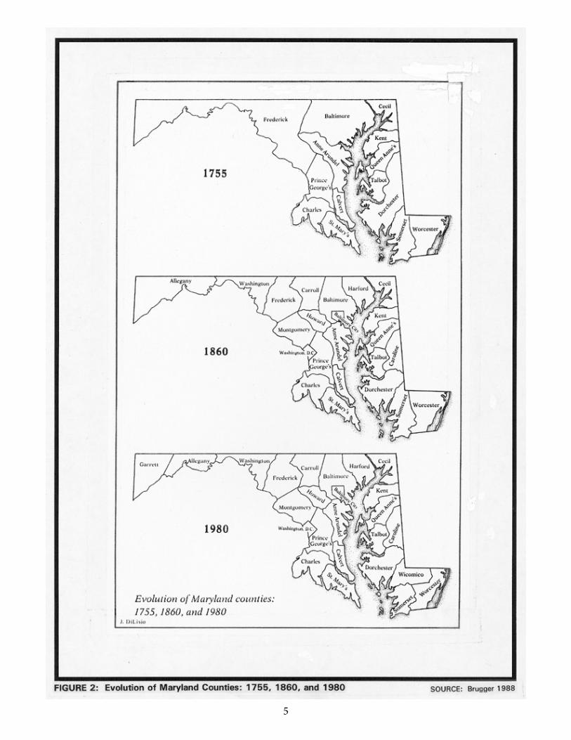
Besides topography and geography, an equally important factor affecting the bridges built in Maryland has been the governmental role in transportation policy, generally constant despite many changes of government. During the early seventeenth century, the European settlement of the area was fostered by the Calvert proprietors and their appointive governors, but the earliest laws concerning transportation were passed by the General Assembly (first convened in 1635 at St. Mary's City) and put into effect by county officials. Initial administration of road work by counties occurred as early as 1642, when the legislature formed Kent County (Brugger 1988:13-14, 799). Although transportation policy goals have changed considerably from the 1630s to the twentieth century, the basic role of both the state government and local officials with regard to roadmaking and bridge building has persisted down to the present day.
A third important influence on the kinds and numbers of historic bridges seen in the state has been the extraordinary series of technological changes affecting the building of roads, canals, railroads, and their attendant structures such as bridges. With the development of cast iron, wrought iron, and finally concrete and steel, the traditional preindustrial bridge construction materials--timber and stone--came to be simply two options available to professional engineers, rather than the only possible choices in constructing durable spans. The coming of improved roads, lock canals, and long railroads in Maryland spurred the popular demand for similarly improved transportation facilities, and this demand in turn, fostered the rise of the American civil engineering profession. Many of Maryland's historic bridges display a deliberately engineered "intermodal" aspect, allowing combinations of water navigation and highway and rail traffic. Historically significant bridge engineers active in Maryland have included Theodore Burr, Lewis Wernwag, James Finlay, Benjamin H.B. Latrobe, Wendel Bollman, C. Shaler Smith, J.E. Greiner, and Daniel B. Luten.
2
2
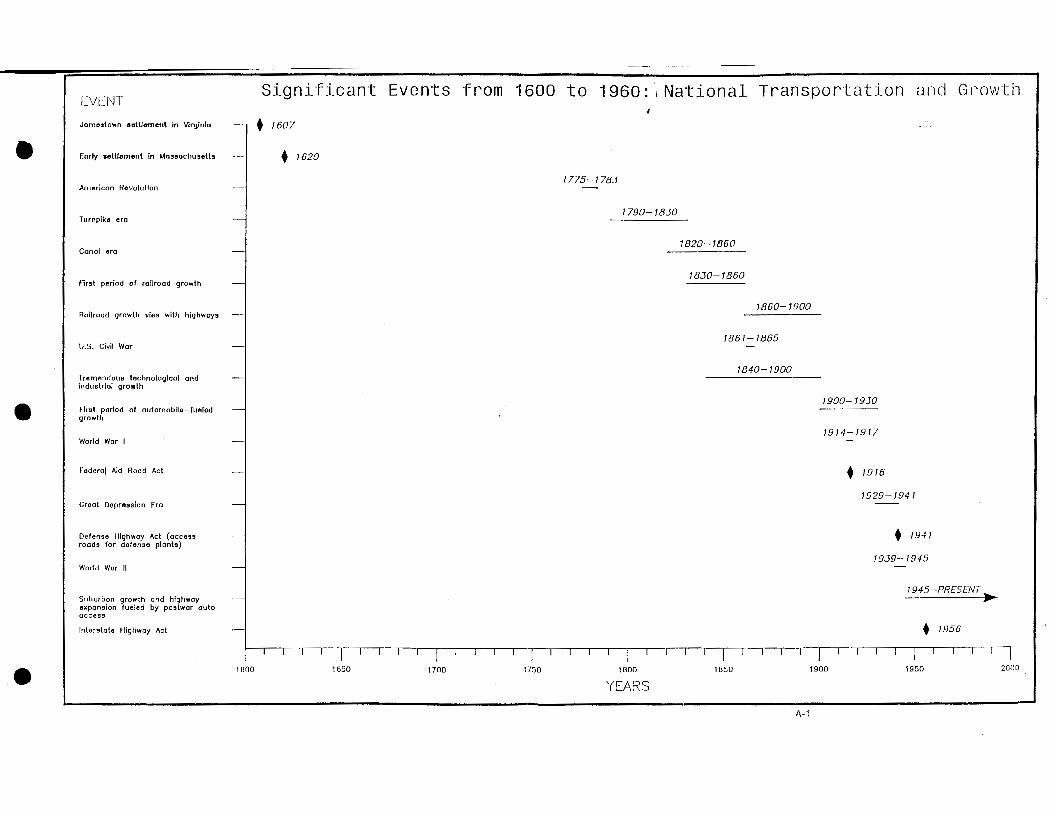
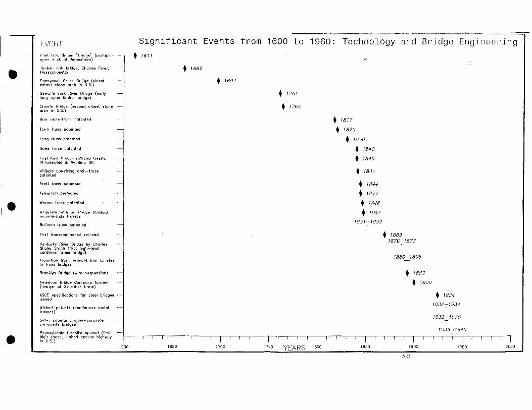
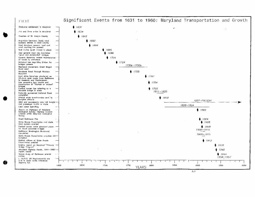
A careful, chronological consideration of these three historic forces--the impact of topography and geography on the development of Maryland's transportation network, the shaping of that network by legislative and county actions, and the revolutionary technological and engineering advance--provides an overall background context which serves to introduce and place within history the variety of historic bridge types found in Maryland. The following narrative section of this report summarizes Maryland's transportation history, placing emphasis on major events and trends that significantly affected bridge design and construction in the state. The seven subsequent sections describe the historical development and appearance in Maryland of significant historic bridge types. Appendix A offers historical timetables relating to Maryland history and the development of bridge technology while Appendix B presents a descriptive listing of bridge builders known to have been active in the state. Appendix C presents guidelines for the identification and evaluation of Maryland's historic bridges.
3
3
SECTION II: MARYLAND TRANSPORTATION HISTORY
THE EARLY TRANSPORTATION NETWORK, 1631-1800
Geography’s Influence
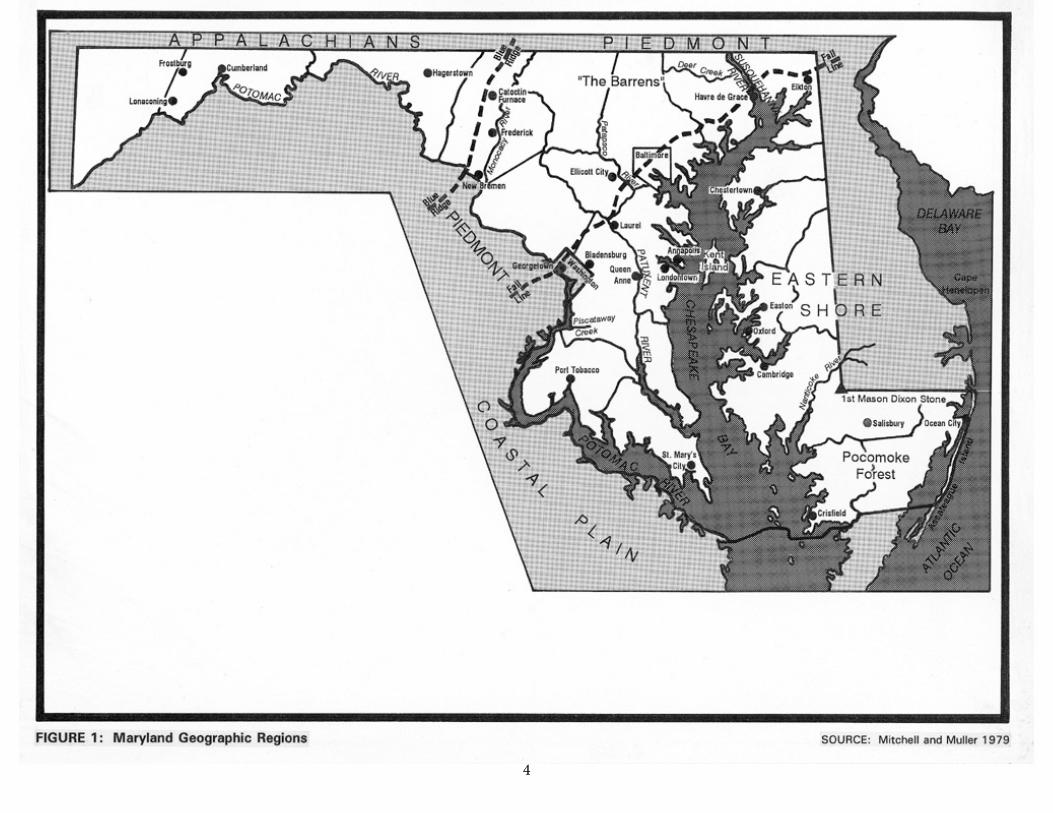
Maryland's distinctive physiography has greatly influenced the development of its transportation network. The is divided into Tidewater, Piedmont, and Appalachian Plateau geographic regions. The Tidewater, or Coastal Plain, area, including the Maryland portion of the so-called “Delmarva” peninsula between Chesapeake Bay and the Atlantic Ocean, as well as parts of Southern Maryland watered by tributaries of the Bay, is characterized by mostly flat or gently undulating terrain crisscrossed by partly tidal streams and rivers such as the lower Patapsco, the lower Patuxent and the Potomac, the Severn, and the Choptank and Nanticoke rivers. Between the fall line and the mountains of western Maryland lies the variegated Piedmont region; in this region the waterways feeding Chesapeake Bay have cut valleys in hilly terrain where Maryland's major building stones, including granites, sandstones, marbles, and slates are found (Maryland Geological Survey 1990). Lastly, the mountainous region of the westernmost sections of Maryland forms part of the steep Appalachian Plateau, a significant American geographic feature marking the first "continental divide" (the only one east of the Mississippi) encountered by road-builders seeking to link Maryland to the Midwest and the West (Mitchell and Muller 1979:1-2) (Figure 1).
Maryland's primarily Tidewater counties include the “Eastern Shore” counties of Worcester, Somerset, Wicomico, Dorchester, Caroline, Talbot, Queen Anne's, and Kent, and the counties of St. Mary's, Calvert, and Charles, west of the Chesapeake Bay. Parts of Cecil, Harford, Baltimore, Anne Arundel, and Howard counties below the fall line also belong to Tidewater territory. These counties also include Piedmont topography, which characterizes all of Carroll County, and nearly the whole of Montgomery County. Baltimore City, encompassing both the lower Patapsco valley (including Baltimore Harbor) and the reaches of Jones Falls and Gwynns Falls above the fall line, is also a mixed Tidewater/Piedmont area. The western counties of Washington, Allegany, and Garrett are in the Appalachian Plateau; but Frederick County straddles the Piedmont and Appalachian regions (Mitchell and Muller 1979:i, 1-2) (Figure 2).
44
5 5
6
6
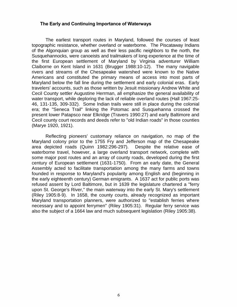
The Early and Continuing Importance of Waterways
The earliest transport routes in Maryland, followed the courses of least topographic resistance, whether overland or waterborne. The Piscataway Indians of the Algonquian group as well as their less pacific neighbors to the north, the Susquehannocks, were canoeists and trailmakers of long experience at the time of the first European settlement of Maryland by Virginia adventurer William Claiborne on Kent Island in 1631 (Brugger 1988:10-12). The many navigable rivers and streams of the Chesapeake watershed were known to the Native Americans and constituted the primary means of access into most parts of Maryland below the fall line during the settlement and early colonial eras. Early travelers' accounts, such as those written by Jesuit missionary Andrew White and Cecil County settler Augustine Herrman, all emphasize the general availability of water transport, while deploring the lack of reliable overland routes (Hall 1967:25-46, 131-135, 309-332). Some Indian trails were still in place during the colonial era; the "Seneca Trail" linking the Potomac and Susquehanna crossed the present lower Patapsco near Elkridge (Travers 1990:27) and early Baltimore and Cecil county court records and deeds refer to "old Indian roads" in those counties (Marye 1920, 1921).
Reflecting pioneers' customary reliance on navigation, no map of the Maryland colony prior to the 1755 Fry and Jefferson map of the Chesapeake area depicted roads (Quinn 1982:296-297). Despite the relative ease of waterborne travel, however, a large overland transport network, complete with some major post routes and an array of county roads, developed during the first century of European settlement (1631-1750). From an early date, the General Assembly acted to facilitate transportation among the many farms and towns founded in response to Maryland's popularity among English and (beginning in the early eighteenth century) German emigrants. A 1637 act for public ports was refused assent by Lord Baltimore, but in 1639 the legislature chartered a "ferry upon St. George's River," the main waterway into the early St. Mary's settlement (Riley 1905:8-9). In 1658, the county courts, already recognized as important Maryland transportation planners, were authorized to "establish ferries where necessary and to appoint ferrymen" (Riley 1905:31). Regular ferry service was also the subject of a 1664 law and much subsequent legislation (Riley 1905:38).
7
6
Early Roadways, 1631-1700
Although navigation persisted into the present century as an important facet of Maryland's transportation history, the continued press of settlers throughout the seventeenth and eighteenth centuries increased the need for official regulation ofroadbuilding activity. In 1661, the General Assembly laid the groundwork forregular postal service with an "Act for the Conveyance of All Letters Concerningthe State and Public Affairs" (Riley 1905:33). Five years later, the Assemblypassed Maryland's first comprehensive general road law, for "marking and making highwayes and making the heads of Rivers, Creeks, Branches and Swampspassable for horse and foot" (Browne 1884:134-135). The 1666 act mandatedthat roads should be marked, indicated that crossings should be placed at thehead of navigation of each body of water, and delegated roadmakingresponsibilities to road overseers appointed by the counties. The law alsosafeguarded the right to make private access roads to farms and mills, andestablished a road work system that included the imposition of penalties payablein tobacco, already the marketable staple of colonial Maryland.
The basic 1666 act was periodically repassed, with amendments,throughout the seventeenth century. The 1671 version, which allowed countycommissioners or "justices" to meet to lay out or amend roads any time betweenSeptember 1 and October 20 of each year, was renewed in 1684 (Browne1884:219-220, 321-322; Browne 1894:486-487). As settlement progressed toward the fall line and Native American territory was penetrated, special laws created acorps of rangers to patrol the fluid frontier. A 1696 order of the governor's council enjoined the rangers to "make and marke severall paths & that the Road whichthey find to be the best and nighest Road, that they double marke the same"(Browne 1900:381). Rangers such as John Oldton thereafter filed reports on their roadmaking. In 1921, historian William B. Marye traced such rough "GarrisonRoads" in Baltimore County, which as late as 1755 embraced the entire areabetween the Patapsco and the Susquehanna (Brugger 1988:772; Marye 1921).
The 1696 order presaged a road-marking law of the same year (copies ofwhich have not survived) and a new general road law of 1699, which set up aprovince-wide system of road marking and, for the first time, required "that allPublick and main roads be hereafter Cleared and well Grubbed fitt for TravellingTwenty Foot wide and good and Substantiall bridges [be] made over all heads ofRivers, Creeks, Branches and Swamps" at the discretion of county justices of thepeace (Browne 1902:475-477). The road-marking system, which mandated three notches on a convenient tree for any road leading to a ferry, may have beenderived from English precedent (Matthew Simons's 1635 Directions for EnglishTravellers noted that directional signs were found in England, especially "in manyparts where wayes be doubtful") (Lay 1992:189). Maryland's road-marking system of 1699 has been acknowledged by historians of public works as the earliest such system in the United States (Armstrong 1976:123).
8
7
The 1699 law, with its significant bridge building and roadmaking provisions, was repassed with little change in 1704 to become (with many subsequentamendments) the basic road act of colonial and early post-colonial Maryland (Kilty 1808:September 1704 Session, Chapter 21). Ample evidence exists that, by1699, roadmaking activity in Maryland, and probably bridge building also, was well underway. Notable early roads included a 1643 (or earlier) "road by land throughthe forest to Virginia" from St. Mary's City (Sioussat 1899:110 note 4); this mayhave been incorporated into the 1650s' road leading from the early capital tosettlements along the lower Patuxent River (Sioussat 1899:110-111). Between1671 and 1684, Cecil County landowner and cartographer Augustine Herrman laid out "cart roads" linking the Delaware and Elk rivers, and leading south toward the"Great Choptank" River; Herrman's roads, and their counterparts on the westernshore of the Chesapeake Bay, became the template for early post roads by 1700(Sioussat 1899:117-118).
Concerning early bridges, a 1697 summary of roads built in Charles Countynoted "ye bridges over Piles his fresh branch" ("Piles" apparently being areference to a landowner rather than a substructure erected on piles) and "yebridges over Zachyah Swamp," a perennial source of travel problems over whichthe legislature mandated an unspecified "crossing" as early as 1674 (Sioussat1899:122). The 1697 Charles County roads summary, and a 1694 BaltimoreCounty court proceeding recommending "good and sufficient bridges for man andhorse to pass over," are the earliest known documents referencing theconstruction of bridges in Maryland (Sioussat 1899:117, 122).
9
8
Colonial and Early National Transportation, 1700-1800
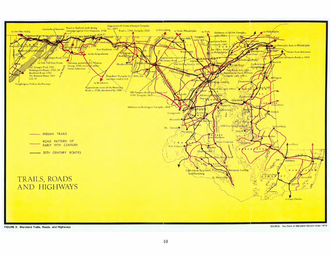
By the first decades of the eighteenth century, Maryland's transportationsystem consisted of numerous navigable waterways (Augustine Herrman's great1683 map gave depth soundings for many of them), and a rapidly growing network of roads (Gould 1915; Quinn 1982:290-293) (Figure 3). Attesting to the influenceof the General Assembly's 1699 and 1704 road-signing provisions, "three notch'droads" (leading first to ferries, then in some cases to bridges) are known to haveexisted in Prince George's County, Baltimore County, and St. Mary's County(Sioussat 1899:120-121). The "good and substantial" bridges desired were alsobeing built; although evidence is scanty concerning their construction, thesestructures were evidently of timber. As the tobacco-boom economy moderatedsomewhat and Maryland agriculture diversified, eighteenth century Marylandwitnessed further official efforts to improve roads and bridges, as well as aid thecounties in their continuing administration of transportation policy and road work(Gould 1915:123-169). In the General Assembly, these efforts culminated inenactment of the first Maryland turnpike legislation, a new general road law, andthe earliest recorded state law mandating a movable-span bridge at acommercially strategic site.
The importance of road overseers and road and bridge maintenance wasfully recognized by the legislature, which in 1715 exempted "overseers ofhighways" from jury duty (Kilty 1808:April 1715 Session, Chapter 37). Strongevidence concerning the prevalence of simple timber beam bridges in earlyeighteenth century Maryland comes from a 1724 law which gave overseers theright to confiscate for bridge repair any suitable trees on adjacent lands, providedthat such trees "be such as are not fit to make clapboards, or cooper's timber, nor for the building or repairing any bridges that are built and maintained at a public or county charge" (Gould 1915:136). The 1724 act also noted that "the severalbridges that have been heretofore over the heads of rivers, creeks, branches,swamps, and other low and miry places, are very much broken and out of repair,and several new bridges are still wanting" (Gould 1915:136). The 1724 law wasrenewed in 1751: not until 1795 did the state grant compensation to the owners of timber confiscated for use in repair or erection of bridges (Gould 1915:136).
109
11
10
The major roads built during the 1700-1800 period were almost exclusively county or privately built and maintained farm roads, but the counties, like theGeneral Assembly, responded to economic pressures and developing patterns of emigration, settlement, and trade (Sioussat 1899:119-125). The principle of least geographic resistance demanded that the earliest major north-south routes pass through Maryland on either side of the Chesapeake Bay. Probably in existenceby 1720, these north-south roads served as early overland links betweenPhiladelphia and Virginia and were described by transportation historianClarence Gould:
One branch ran down the Eastern Shore, crossed the Elk River atBohemia Manor, thence to Frederick and Georgetown on theSassafras River, thence to Chestertown on the Chester River,thence either to Rock Hall or east neck island on the bay side ofKent County and by boat to Annapolis, or across the river atChestertown and down through Queen Anne's County to KentIsland, where a boat was taken for Annapolis. The other branch of the road [from Philadelphia] reached Annapolis around the head of the bay, running past the head of Elk River to North East, toSusquehanna ferry near Port Deposit, to Joppa, to Baltimore,thence either across the Patapsco at Ferry Bar or around by ElkRidge, and to Annapolis. A little way from Annapolis, the roadagain divided, one branch crossing the Patuxent at Queen AnneTown and leading to Upper Marlboro and Addison's ferry oppositeAlexandria, and the other crossing the Patuxent at Nottingham andpassing through Piscataway to the main ferry across the Potomacnear the mouth of Pope's Creek [Gould 1915:125].
As Maryland colonial settlement progressed westward, the "Great WagonRoad" and its offshoots were gradually extended by the 1730s from the key portof entry at Philadelphia into the Maryland hinterland between Frederick andHagerstown (Rouse 1973). Numerous settlers, especially the so-called"Pennsylvania Germans" of German or Swiss heritage, utilized these routes intothe rich farm valleys of western Maryland. Meanwhile, Prince George's Countyby 1739 had a network of more than fifty roads and had authorized a road up the Potomac Valley to the mouth of the Monocacy River (Pearl et al. 1990). Thelatter location, from an early date the site of a large grain mill as well as animportant ford of the Potomac, was linked to Baltimore by the 1750s. Roadswhich today bear names such as "Monocacy Road" and "West Old BaltimoreRoad" in Montgomery and Frederick counties are legacies of this trade patterninvolving carriage of goods from Virginia through "Mouth of Monocacy" toBaltimore Town, founded in 1729 but greatly boosted by this western overlandconnection (Lubar 1991:19-26).
12
11
In the far western portion of Maryland, military action during the Frenchand Indian War occasioned the building of Braddock's Road in 1755, linking Fort Cumberland, near present-day Cumberland, with the Pittsburgh region throughwhat are now Allegany and Garrett counties. Braddock's road remained a rough route west until it was superseded in the early nineteenth century by the largelyparallel National Road, the first federally built road in the United States. TheCumberland vicinity was also linked during the 1750s by a military road to FortBedford (at modern Bedford, Pennsylvania), where British troops mustered forthe 1758 attack on the French Fort Duquesne (at present Pittsburgh) (Leviness1958:13-17).
The Tidewater and lower Piedmont regions, by contrast, werecharacterized by the tobacco-related "rolling roads." There were also overlandportage routes at locations in Cecil County and Talbot County where thenavigational heads of Delaware River tributaries and Chesapeake Bay feederswere only a few miles apart (Gould 1915:127-128, 142-144). Large casks oftobacco were rolled by main force, or pulled by draft horses, along rolling roadsthat connected plantations with river landings. By the mid-eighteenth century,although county courts and the General Assembly had long recognized thedamaging and cheapening effects such transportation over many miles had onthe packed tobacco, laws were passed to regulate but not prohibit the system of rolling roads. These Eastern Shore portages remained economically useful intothe nineteenth and twentieth centuries, when they became the routes ofimproved roads, turnpikes, railroads, and the Chesapeake and Delaware Canal(Gould 1915:127-130, 142-143).
A larger transportation network, however, did not necessarily bring betterroad conditions. Eighteenth century travelers repeatedly noted that even themajor post roads to Annapolis were enclosed by dark forests; planters andfarmers kept the through road back from the edge of their property in order tomaximize cultivated acreage (Gould 1915:131-132). The eighteenth centurygrowth of Baltimore as a market city, the expansion of wheat growing inMaryland, and early industrialization in the form of gristmills and iron furnacesalso kept the General Assembly's attention focused on the sometimes alarminggap between the ideal and the real on Maryland's roads (Olson 1980:5-9). Laws of 1753 and 1756, noting that in icy weather travel to Annapolis was ofteninterrupted, took steps to guarantee that millers preserve existing bridges andbuild new ones over millraces and tailraces (Kilty 1808:October 1753 Session,Chapter 16, and October 1756 Session, Chapter 12). The latter requirementheld force well into the nineteenth century in many of Maryland's Tidewatercounties (Kilty 1808:October 1753 Session, Chapter 16, note).
Military supply difficulties during the Revolution (1775-1783) highlightedthe sorry condition of Maryland's overland transportation system (Leviness1958:17). During the early national period (1783-1800), the newly independent
13
12
state began to adopt a more activist role in the proper development ofdependable roads and bridges. Taking initial shape through legislation enactedin the late 1780s and early 1790s, the Internal Improvements movement inMaryland was characterized from the first by a reliance on public-privatepartnerships, in which the balance of official action and entrepreneurial incentive often varied (Livingood 1947:7-20; Rubin 1961:63-72). Both turnpike and canalprojects, however, incorporated provisions for bridges.
Baltimore interests, seeking to keep the trade of western Maryland and theSusquehanna Valley away from Philadelphia, demanded better roads; a petitionsubmitted prior to the 1787 turnpike legislation depicted conditions as they were:
The public roads leading from Baltimore-town to the western partsof this state, by means of the great number of wagons that use the same, are rendered almost impassable during the winter season,and the ordinary method of repairing said roads is not onlyinsufficient, but exceedingly burdensome; and the establishment ofseveral turnpike roads in the said county would greatly reduce theprice of land-carriage of produce and merchandise, and raise thevalue of the land in the said county, and considerably increase thecommerce of the state [Hollifield 1978:2].
The 1787 act responding to this appeal authorized three major turnpikes to be built and administered by Baltimore County as toll roads. A turnpike fromBaltimore to Reisterstown would diverge at the latter community to reach bothWestminster and Hanover, Pennsylvania. A road from Baltimore to Frederickwould also be built, along with a turnpike linking Baltimore and York,Pennsylvania (Sioussat 1899:144-145). By 1805, the plan for countyadministration having failed, none of the three turnpikes was completed, andthere is no evidence that any of the sections finished utilized improvedtechnology (Hollifield 1978:2). Nonetheless, with private financial backing later in the nineteenth century, all three roads would eventually be placed in operation,as the precursors to present-day Reisterstown Road (with Westminster andHanover pike extensions), Frederick Road, and York Road (Hollifield 1978).
In 1794, the General Assembly revised the general road law of the state,leaving most road work in the hands of the counties but setting up a system ofLevy Courts to govern road and bridge construction (Kilty 1808:November 1794Session, Chapters 52 and 54). Bridge repair specifically was to be performed by laborers hired by the courts, except in cases involving "framed or arched bridges exceeding fifteen feet in length" (Kilty 1808:November 1794 Session, Chapter52). This was an early recognition that construction and maintenance of suchbridges might involve special expertise not possessed by the average laborer. A county's levy court justices were also permitted to raise through taxes as muchas 30 pounds annually for repair of a single bridge and as much as 100 poundsfor construction of any new bridge (Kilty 1808:November 1794 Session, Chapter
14
13
54). Significantly, the 1794 law required cooperation between adjoining counties in building or repairing bridges over county lines. Such bridges were to becontracted out to workmen through a process of bidding and receipt of proposals (Kilty 1808:November 1794 Session, Chapter 54).
Like previous general road laws, the 1794 enactments were an attempt to systematize and control the burgeoning road network of Maryland in the earlyperiod of agricultural consolidation and waterpowered industrialization. The1780s and 1790s also saw legislative chartering of bridge companies and canals.Associated persons were authorized to build an unspecified span over thePotomac, and in 1795 a drawbridge was specified for the Eastern Branch of thePotomac (or Anacostia River), where both the port of Bladensburg and thenation's capital (founded 1791) were located (Kilty 1808:November 1791Session, Chapter 81, and November 1795 Session, Chapter 62). Legislationsetting up the Susquehanna and Tidewater Canal and the Chesapeake andDelaware Canal included provisions requiring each canal company to erectbridges over its waterway wherever such crossings were necessary or customary (Kilty 1808:November 1799 Session, Chapter 16).
These early Assembly charters for private firms to build transport routes and associated structures anticipated the phenomenal build-up of Maryland's transportation network during the nineteenth century, a growth largely planned by corporations working in tandem with state, local, and federal officials. The canal laws of the 1780-1800 period, as well as the turnpike legislation and the general road law mandating a proposal and bid system for intercounty bridges, signified that economic and technological change was on its way, reflecting the impact of the Industrial Revolution on Maryland's time-honored roadmaking and bridge building traditions.
15
MARYLAND TRANSPORTATION TRANSFORMED, 1800-1900
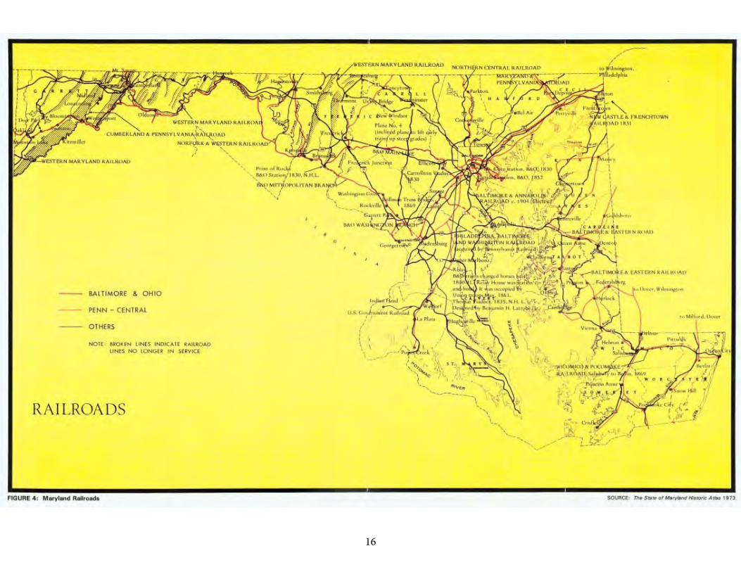
During the nineteenth century, Maryland's transportation network experienced tremendous change (Figure 4). The primary themes in the transformation of travel in the state, including the development of private toll roads or turnpikes, the construction of the National Road, the Chesapeake and Ohio Canal, the Chesapeake and Delaware Canal, and the Baltimore and Ohio Railroad, and the ultimate demand for better county roads, have been well covered by numerous historians, including St. George Leakin Sioussat, Joseph Durrenberger, Charles Leviness, Sherry Olson, Ralph Gray, Herbert Harwood, and William Hollifield (Durrenberger 1931; Gray 1985; Harwood 1979; Hollifield 1978; Leviness 1958; Olson 1980; Sioussat 1899). The following discussion is a concise summary of such themes and their relation to events and trends which affected or shaped bridge building in Maryland.
1614
17
15
Turnpikes and Turnpike Bridges
The 1787 legislation allowing Baltimore County to build improved roads, or turnpikes, to York, Frederick, Reisterstown, Westminster, and Hanover failed to produce complete highways to those destinations. Baltimore County nevertheless spent considerable sums improving portions of the old routes and was ultimately reimbursed by the General Assembly, which sought ways to attract private capital to the projects (Hollifield 1978:2). Turnpiking a road in the early national era meant straightening, rebedding, and resurfacing an old dirt route with various combinations of broken stone or gravel, or laying out by exact survey an entirely new route to take advantage of the terrain. With the scientific innovations in methods of stone surfacing and road drainage developed by British engineers Thomas Telford and James McAdam coming into American use during the first three decades of the nineteenth century, state boards of public works and private turnpike companies increasingly hired trained civil engineers to survey roads and build bridges along them (Lay 1992:110-111).
Between 1796 and 1801, five separate turnpike companies were chartered, none of which successfully completed a road (Sioussat 1899:145). During the legislative session of 1804-1805, however, the Assembly created three highly important turnpike companies: the Baltimore and Frederick Town Turnpike Company, which built the first improved link to the West (Frederick Road) through Ellicott City, New Market, Frederick, Middletown, and Boonsboro; the Baltimore and Reisterstown Turnpike Company, which with its two northern branches tapped the rich farm country of south-central Pennsylvania; and the Baltimore and York Town Turnpike Company, which connected Pennsylvania roads crossing the Susquehanna (Durrenberger 1931:66).
These companies overcame numerous challenges of topography and construction in order to build their roads. Reaching toward western Maryland, the Frederick Turnpike was gradually extended (in part, via roads financed and built by the state's banks under agreement with the General Assembly) to meet the National Road at Cumberland. Another branch of the pike led to Harper's Ferry and the Shenandoah Valley of Virginia. Treasury Secretary Albert Gallatin's famous 1808 study on internal improvements, and Governor Goldsborough's 1818 "Executive Communication on the Subject of Turnpike Roads" offered progress reports on the various turnpikes chartered by the Maryland legislature (Gallatin 1968:60-67; Goldsborough 1818). By 1807, the Baltimore and Reisterstown pike had been surveyed and was completed for ten miles of its length at a cost of $10,000 per mile. The Baltimore and Frederick Turnpike had built some 37 miles of its 62-mile total, while a restrictive clause delayed construction of the turnpike to York until after 1807 (Durrenberger 1931:66-67).
Goldsborough's 1818 report was based on questionnaires sent to each turnpike company (Goldsborough 1818). By that year, having witnessed the
18
16
advantages of private capitalization of improved roads, the Maryland legislature had authorized a number of other turnpikes, including the Falls Pike (Falls Road), the first improved Baltimore and Washington Turnpike (chartered 1813 to follow approximately the route of today's Baltimore-Washington Boulevard or Route 1 through the old port of Bladensburg to Washington), the Baltimore and Havre de Grace Turnpike (an 1813 precursor to present Old Philadelphia Road), and the New Castle and Frenchtown Turnpike (also chartered 1813 to carry goods over one of the old portage routes between the Chesapeake Bay and the Delaware River) (Durrenberger 1931; Holmes 1962). Other private toll roads, such as the Westminster, Taneytown and Emmitsburg Turnpike, and the Belair Turnpike (predecessor of Belair Road), were deliberately laid out to draw the commerce of the Susquehanna Valley away from Philadelphia and toward Baltimore (Durrenberger 1931).
The Goldsborough report documented use of both simple timber beam and stone arch bridges on the early turnpikes of Maryland. On the Baltimore and Reisterstown Turnpike, completed on January 8, 1810, with twelve tollgates, "many bridges" had been built by the company "of solid materials, at a very great expense," but no special bridge tolls were charged. The Baltimore and York Turnpike, finished in 1811, included five one-span stone arch bridges and two two-span stone arch bridges, on which a total of over $15,000 had been spent. On the Frederick pike "four considerable bridges" had been erected (over Gwynns Falls, the Patapsco, the Monocacy, and Catoctin Creek). The turnpike company's $56,000 four-span Monocacy Bridge (the so-called "Jug Bridge," a stone structure southeast of Frederick which stood until 1942) was built in the expectation that the company would defray the cost by tolls. When this was not authorized, no more money was available for turnpiking or improving the old Frederick road (Goldsborough 1818).
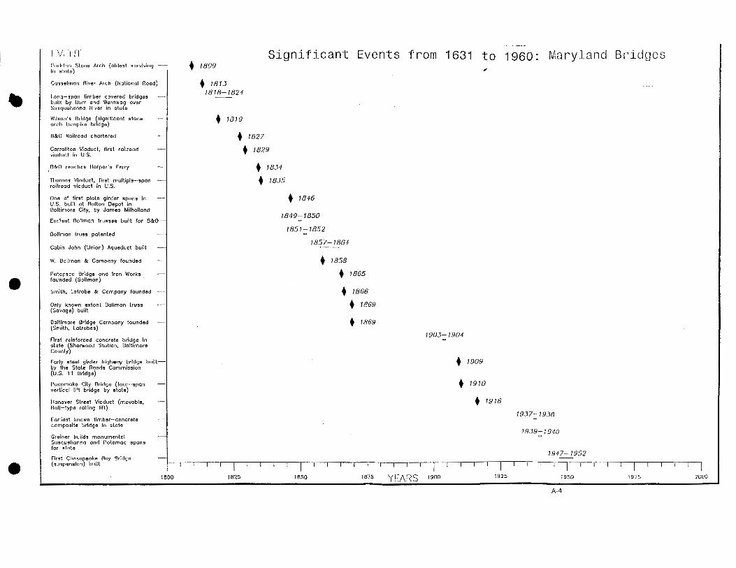
In the early nineteenth century, the companies' clear preference for stone arch bridges at important Piedmont and Appalachian Plateau crossings reflected a growing popular demand in those areas for sturdy structures able to withstand the pressures of frequent wagon traffic as well as the force of water, ice, and flood debris along streams and rivers with moderate or high slopes. The bridges' general durability has been demonstrated; the oldest known bridges extant in Maryland are the Parkton Stone Arch Bridge over the Little Gunpowder, built in 1809 in northern Baltimore County along a piked route (Meyer 1981:5-6), and Washington County's notable collection of stone arches, all probably erected between 1819 and 1863 although some undated examples may possibly predate the Parkton arch (Mish and Cottingham 1977). Numerous stonemasons in Maryland developed skill in the layout and building of such spans, and noted engineers such as the Shrivers and Latrobes worked for the turnpike firms (Durrenberger 1931).
In the Tidewater or Coastal Plain region, where drops in elevation were not so large, few stone bridges appear to have been constructed (no major turnpikes
19
17
except the New Castle and Frenchtown pike were built in the Delmarva peninsula) (Holmes 1962). On major rivers like the Susquehanna and Potomac, however, the earliest substantial spans were often long covered wooden bridges, supported on only a few piers in order to avoid obstructing heavy water flow (American Society of Civil Engineers 1976:7-14). A lengthy obstacle to the nation's earliest east-west turnpikes, the Susquehanna especially challenged the talents of the country's foremost timber bridge builders. In Maryland between 1815 and 1825, both Theodore Burr, inventor of the Burr arch type of covered bridge, and Lewis Wernwag, expert bridge constructor and designer of the famous "Colossus" bridge over the Schuylkill at Philadelphia, built long-span covered bridges at Conowingo and Port Deposit (Maryland Historical Trust 1970-1993). No longer extant, these bridges nevertheless mark the period of craftsman tradition in Maryland bridge building, as do the many stone arches erected by masons James Lloyd, Silas Harry, and John Weaver in western Maryland (Mish and Cottingham 1977).
Baltimore's preeminence as a destination of turnpikes built between 1810 and 1840 attested to that city's extraordinary growth after the Revolution. By about 1825, Baltimore was the third largest city in the United States and the terminus of seven turnpikes (Durrenberger 1931:69). Within the city, a variety of wooden bridges built under the City Commissioners' aegis (including an early drawbridge at Light Street) provided the beginnings of an urban infrastructure for the transport of freight and goods (Olson 1980). Even so, competition with such expanding port cities as Philadelphia, New York, Pittsburgh, and New Orleans kept Baltimore entrepreneurs alert to the possibility of new connections with the Midwest, where farms were rapidly replacing the old trans-Appalachian wilderness of the colonial era. Four major nineteenth century engineering projects in Maryland—the National Road, the Chesapeake and Ohio Canal, the Chesapeake and Delaware Canal, and the Baltimore and Ohio Railroad—emerged from the public effort to strengthen Baltimore's marketing position in the years prior to the Civil War (Livingood 1947; Rubin 1961). Each project directly affected the bridge building history of the state in the period before the introduction of automobiles and trucks.
20
18
The National Road
Some of Maryland's most significant bridges are located along the route of the National Road, a nationally significant improved turnpike constructed in the early nineteenth century from Cumberland to Uniontown, Pennsylvania, as the first federally built highway in the United States. In 1806, Congress authorized construction of a road "from Cumberland or a point on the northern bank of the river Potomac, in the State of Maryland, between Cumberland and the place where the main road leading from Gwynn's to Winchester, in Virginia, crosses the river, to the State of Ohio" (Sioussat 1899:183). By statute, Maryland, Pennsylvania, and Virginia granted permission for the so-called "U.S. Road" (also to be known as the Cumberland Road as well as National Road), and between 1811 and 1818 the road was built under the supervision of topographical engineers from the U.S. Army (Kanarek 1976; Sioussat 1899:184-185).
From 1818 to the early 1830s, linked to central and eastern Maryland via turnpikes from Cumberland through Hagerstown and Frederick, the National Road was maintained under Federal administration (Kanarek 1976:11-17). The unprecedented nature of the road's sixty-foot right-of-way was a perennial problem for nearby residents who built fences and even houses on the land allotted for the road. Repair of the National Road was a still worse challenge, as narrow iron wagon wheel rims and dragged sawlogs tore up the roadway surface. In 1823, U.S. Army engineer David Shriver, Jr., observed that "the road has suffered so much, that its original form is lost, and the sum in hand is not sufficient to stop the progress of ruin on it" (Kanarek 1976:13). Between 1832 and 1835, the U.S. War Department expended over $900,000 on National Road repairs, which included laying a new McAdam (or macadam) surface on the road (Kanarek 1976:14-17).
Semicircular stone masonry arches and culverts were the preferred bridges constructed along the route of the National Road. Where streams and rivers were encountered at an angle to the roadway, the so-called "S-bridges" were built, with a shape that allowed the bridge to be erected perpendicular to the bank (Ierley 1990:105). A significant, extant Maryland stone arch bridge, the Casselman River Bridge at Little Crossings, was built in 1813 by contractors Kerns and Bryson to a design by David Shriver to carry the National Road over the Casselman River near Grantsville, Garrett County (Little Crossings Historical Committee 1964). At least one original National Road stone arch culvert has also been located in the same area (Ware 1991:234).
Indicating the faith Maryland authorities placed in stone arch turnpike bridges, an 1834 dispute between Maryland and the U.S. Army engineers concerning the proper type of bridge for the National Road crossing of Will's Creek near Cumberland was resolved in favor of a stone span, over the objections of Captain Richard Delafield, who wanted a less expensive wooden superstructure on stone abutments and wingwalls. Bridge and culvert maintenance on the road
21
19
remained a regular, indeed chronic concern after the Maryland part of the National Road was taken over by the state in 1835 (Kanarek 1976:11-17).
By 1878, when the General Assembly turned over ownership of the National Road to Allegany and Garrett counties (Maryland General Assembly 1878:256-258), competition from the Baltimore and Ohio and other railroads had reduced commercial through traffic on the decayed road to a trickle. The Maryland Geological Survey's 1899 report on highways sadly noted that the National Road through Maryland was too narrow, muddy, and virtually impassable at points, and that bridge parapets on the Casselman River arch were disintegrating (Johnson 1899:214-215, 234-235). Renewal of the road as U.S. 40 awaited the coming of auto and truck traffic during the twentieth century (Allen 1991:38-43).
Maryland's Canals: C&O and C&D
Like the National Road, the earliest professionally engineered lock canals in Maryland represented public attempts to capture western and southern trade. Canal construction involved creating artificial, commercial water routes, often alongside a major river which would provide a water supply for operation of locks and basins. Existing roads had to be carried over or under canals, which themselves were sometimes required to cross roads or rivers on aqueducts. Bridge building, particularly stone masonry, was given impetus by the chartering of canal companies in Maryland.
Between 1824 and 1850, the Chesapeake and Ohio (C&O) Canal was constructed from the vicinity of Georgetown, near Washington, D.C., to Cumberland, Maryland, although its promoters hoped to extend it over the mountains to Ohio. Though economically outranked by the Baltimore and Ohio (B&O) Railroad, the canal operated well into the second decade of the twentieth century as a means of transporting goods and crops from western Maryland to the coastal and Atlantic trade. The Chesapeake and Delaware (C&D) Canal, completed in 1829 to link the Chesapeake and Delaware bays and widened to become a "ship canal" in the early twentieth century, currently remains in operation (Gray 1985).
Both canals necessitated bridges, but the types built evidently varied considerably. On the line of the C&O, from Georgetown west through the vicinity of Cumberland, the canal was spanned by dressed stone masonry arch bridges, and was occasionally carried (as at Monocacy River) by stone aqueducts (Sanderlin 1964) (Surviving examples of such structures, sometimes built of distinctive red Seneca sandstone, as well as various small bridges associated with lock complexes, have been documented and recorded by an ongoing project of the Historic American Engineering Record of the National Park Service [Sanderlin 1964]). The C&D, by contrast, was spanned by several covered timber bridges
22
20
and also included several early movable bridges (pivot or swing type). The fairly low profile of the C&D Canal obviated the need for major aqueducts. During the twentieth century, however, vertical lift bridges would be erected over the C&O at Williamsport (a railroad span) and over the C&D at Chesapeake City (to carry a highway) (Gray 1985).
The B&O Railroad and Maryland's Bridges
The C&O Canal's great rival during the nineteenth century was the Baltimore and Ohio Railroad. The B&O line transformed the Maryland landscape between 1830 and 1900 and ushered in momentous changes in bridge building technology (see Figure 4). The B&O made stone viaducts and then metal truss bridges acceptable to the general public by demonstrating that they would work if properly engineered. As the acknowledged innovator among early American railroad companies, the B&O was likewise a training ground for American civil engineers; such distinguished engineers as Benjamin H. Latrobe, Jonathan Knight, William G. McNeill, Caspar Weaver, Stephen H. Long, Wendel Bollman, and John E. Greiner began as railroad engineers and played significant roles in Maryland's bridge history. Although the spans built by the B&O and other railroads in the state generally were not intended for highway travel, the heavy loads they regularly carried proved the viability of such bridge types as the high masonry arch, the Long truss, the Bollman truss, the plate girder, and the timber trestle (Harwood 1979).
The history of the Baltimore and Ohio Railroad has been chronicled in detail by Herbert H. Harwood, Jr., in his Impossible Challenge (Harwood 1979). Technological historian Robert Vogel summarized the "firsts" of the B&O: "first practical railroad in America; the first to use an American locomotive; the first to cross the Alleghenies" (Vogel 1964:84). The B&O main line as fully articulated between 1829 and 1860 ran west from Mount Clare Station in Baltimore along the Patapsco valley through Ellicott City and Sykesville to Point of Rocks, Brunswick, and Harper's Ferry, and along the Potomac Valley to reach Cumberland and points beyond (Harwood 1979:14-34). Its success assured from an early date, the B&O throughout the nineteenth century built spur lines and access tracks to prominent mills, factories, mines and quarries, and lumber stands in the Piedmont and Appalachian Plateau counties of Maryland (Harwood 1979:206-396).
The initial stretch (the old main line) of the railroad west of Baltimore became the location of several imposing stone arch bridges, after the directors and engineers led by Jonathan Knight determined that most of the first bridges immediately west of the city should be of masonry (Harwood 1979:15-16). (Colonel Stephen H. Long entered a dissent to this decision, and later constructed the only major timber bridge—the Jackson Bridge, a covered wooden "Long truss" of his design—on the first division of the B&O, to carry the Washington and
23
21
Baltimore pike over the tracks [Harwood 1979:15-16]). Notable among these stone arch bridges is the nationally significant, extant Carrollton Viaduct, a two-span granite structure 312 feet long and including an 80-foot main arch over Gwynns Falls. Built in 1829-1830, the Carrollton Viaduct is the oldest surviving railroad bridge in the United States (Schodek 1987:77-78). Other extant or partially extant stone arches on the B&O's first division include some small spans near Baltimore, the remains of the Patterson Viaduct, at Ilchester on the Patapsco, and part of the Oliver Viaduct at Ellicott City (Harwood 1979:398).
Between 1833 and 1835, as the B&O constructed its Washington Branch south of the old main line, the well-known Thomas Viaduct was erected over the Patapsco near Elkridge. This structure, like the Carrollton Viaduct a major engineering landmark, is the oldest multiple arch railroad viaduct in the United States and possibly the best-known historic bridge in Maryland. Designed by Benjamin H. Latrobe and built in 1835, the Thomas Viaduct is 612 feet in length and consists of eight 58-foot arches built on a curvature that was itself revolutionary for its time (Harwood 1979:206-207). Still in service, "Latrobe's Folly" stands today as a physical legacy of the rise of the civil engineering profession in bridge building, as reflected in early nineteenth century Maryland railroading practice.
The Baltimore and Ohio Railroad prior to 1900 was carried on a variety of technologically innovative bridge structures in addition to the solid stone arches and imposing viaducts of its first division. Between 1840 and 1850, at Elysville (later Daniels) on the Patapsco and Harper's Ferry, covered wooden truss bridges of Latrobe's design, in which some cast iron was utilized in joints and wrought iron for certain tensile members, marked the key transitional phase from wood to iron in bridge building (Harwood 1979:48). Lewis Wernwag, who had built long-span timber bridges over the Susquehanna, was brought in by Latrobe to construct spans at Harper's Ferry. By 1849, when Latrobe's annual chief engineer's report noted that new bridges with "a superstructure of iron upon stone abutments" would be erected at Savage and Bladensburg, the railroad was following the lead of prominent bridge engineer Squire Whipple, designer of a series of small iron truss bridges over the Erie Canal in the early 1840s. Latrobe's "new bridges" of 1849 were of another new design, the Bollman truss, pioneered by the B&O's own master of road Wendel Bollman of Baltimore, who had formerly served the railroad as foreman of bridges (Vogel 1964).
The Bollman truss, discussed in further detail below in the section entitled "Metal Truss Bridges," was structurally a combination truss and suspension bridge, in which a system of lines of trussing carried individual panel loads to the ends of the frame by members acting independently of one another. Patented in 1851, with a renewal of rights in 1866, Bollman's design was utilized extensively along the B&O line (as a through truss in some cases and a deck truss in others) and was marketed throughout the United States and South America by Bollman's Baltimore-based bridge companies, W. Bollman and Company and the Patapsco
24
22
Bridge Company, between 1855 and the 1870s. Appropriately, Savage, Maryland, where one of the first two Bollman truss bridges was built in 1850, is the location of the last known surviving Bollman truss. Although not the original span at the site, the bridge has been restored by Howard County and designated a National Civil Engineering Landmark and a National Historic Landmark (Vogel 1964).
The Bollman trusses on the B&O heralded the widespread use of metal truss bridges in Maryland for highways as well as railroads. As technology progressed and mathematical understanding of truss analysis became more refined, Bollman's unusual design was largely superseded by less complex, easier to market Pratt and Warren metal truss bridges (see "Metal Truss Bridges," below). On the B&O and many other Maryland railroads, the late nineteenth century witnessed adoption of Pratt and Warren designs as well as use of highly adaptable, simple structure types such as the metal plate girder (the earliest known example of this type in the United States was a 54-foot prefabricated single-track deck girder erected by the Baltimore and Susquehanna Railroad at Bolton Station in 1847), and the wooden timber trestle, although reliable masonry arch bridges and viaducts were still being built throughout the century (DeLony 1993:43; Harwood 1979; Tyrrell 1911:195). Trusses as well as timber beam bridges supported on timber piles were used by railroads active on the Eastern Shore between 1860 and 1900 (Hayman 1979).
Bollman's companies were among the earliest to actively market truss bridges as easy to erect; the historic span at Savage still bears numerical imprints intended to guide work crews in the proper placement of the members. After the Civil War, however, a full complement of prominent metal truss bridge building firms became interested in selling trusses to railroads and county commissioners. Baltimore-based companies known to have built trusses in Maryland included Bollman's two firms, the Baltimore Bridge Company, led by Charles and Benjamin Latrobe and Charles Shaler Smith, and the H.A. Ramsay firm (Howard 1873:216-218). Firms located outside of the state but marketing in Maryland between 1865 and 1900 were the King Bridge Company and the Wrought Iron Bridge Company, both of Canton, Ohio; the Pittsburg Bridge Company; the Penn Iron Bridge Company; Nelson and Buchanan (who also acted as agents for Pittsburg Bridge Company); the Roanoke Iron and Bridge Company; and the York Bridge Company (primarily active after 1900) (Maryland Historical Trust 1970-1993).
Pioneered by the Baltimore and Ohio, railroad construction in Maryland during the nineteenth century included many important freight and passenger lines, such as the Northern Central and the Western Maryland Railway (Gunnarson 1990). An array of railroads also served the Delmarva peninsula, connecting Tidewater farms and towns and linking them to markets in Baltimore and Philadelphia (Hayman 1979).
25
23
The Road Network and the 1899 Report on Highways
Although major improved turnpikes, canals, and railroads dominated Maryland's commercial and industrial transportation in the nineteenth century, a highway network was also gradually developing. The state's basic system of county roads, and private roads built to access farms or factory sites, slowly expanded during the 1800-1900 period, under the patronage of the General Assembly and county officials. After the pioneering private toll road legislation of 1804-1805, many other turnpike laws were enacted, most of which resulted in actual construction of pikes. Historian Joseph Durrenberger observed that Maryland, to a greater degree than Pennsylvania, New York, or New Jersey, did not summarily abandon its turnpikes to decay, and in 1899 had a greater proportion of turnpike mileage in actual operation than did the other Mid-Atlantic states (Durrenberger 1931:161).
In 1818, the county courts were authorized to regularly appoint three-person panels of viewers to inspect potential or proposed road and bridge locations and "examine whether the public convenience requires it" (Sioussat 1899:154). The 1818 law was expanded in greater detail in the 1853 code, which, with subsequent revisions and amendments of 1856, 1860, 1874, and 1888, governed county administration of public roads and bridges until the end of the century (Sioussat 1899:154). The legislature also maintained its protective interest in the encouragement of private access roads; the right to construct such roads was specifically extended to quarry operators and mine owners (1833) and to millers, factory owners, limekiln operators, and distillery owners seeking railroad access (1836) (Maryland General Assembly 1836:n.p., Chapter 255). By an 1835 law, plans for private roads had to be submitted to the county levy courts (Maryland General Assembly 1835:n.p., Chapter 253).
State maps and county atlases published in Maryland between 1865 and 1900 depicted a full road network, with numerous overland routes clearly shown even in remote or mountainous regions (Hopkins 1877, 1878a, 1878b, 1878c, 1879). While a well-interlaced array of roads certainly existed near Baltimore and in the western Tidewater counties, unfortunately, many of the roads so depicted were largely unimproved dirt routes, dusty in dry weather, impassable due to mud in rainy times, and either neglected or filled with deep wagon wheel ruts from too much travel (Johnson 1899). By the 1890s, however, with bicycling a popular pastime and automotive traffic on the horizon, voices were raised for road reform. The 1894 statement of the Maryland Road League offered a pragmatic analysis of the counties' predicament:
The Commissioners are already authorized by statute, in their discretion, to commit the roads and bridges to experts, but unanimously refuse to do so, probably for the reason, among others, that they do not feel warranted in incurring the resulting expense. It
26
24
is likewise not worth while to recommend that they should be compelled to employ engineers (they probably would not consent to it in the first place); while, if such a law were forced upon them, lack of funds would probably compel them to employ inefficient men, and no good would be attained [Maryland Road League 1894:8-9].
The league recommended that the state create an "engineering department" and place its services at the command of each county, which they hoped would eventually set up a county engineer's office of its own. Although many counties were slow to professionalize their road and bridge functions, these recommendations gathered force during the 1890s and finally took shape in the Maryland Geological Survey's supervision of state road-building (1899-1908), the 1901 founding of the Baltimore County engineer's office, and the creation of the Maryland State Roads Commission in 1908 (Maryland Road League 1894). It is noteworthy that Baltimore City had employed professional civil engineers as early as 1880 and had begun a separate roads engineer office by 1898 (Olson 1980).
Fittingly, the nineteenth century era in Maryland transportation history closed with publication and widespread discussion of the 1899 Report on the Highways of Maryland, issued by the Maryland Geological Survey under authority of an 1898 act of the General Assembly. The report included a full survey of Maryland's roads by county, and for the first time in Maryland history scientifically analyzed the relation of topography, climate, and geology to road making in the state. Traditional roadway surfacing practices, whether they involved use of gravel, broken stone, or oyster shells (available in abundance in the Tidewater counties), were generally criticized (Johnson 1899; Sioussat 1899).
The report also found most Maryland bridges under 30 feet in length to be of simple timber beam, or king-post or queen-post form, although these spans were rapidly being replaced with short iron bridges, "some of which are of a flimsy construction" (Johnson 1899:206). The Maryland highway geologists recommended for short spans "a combination of masonry and I-beams, between which are transverse arches of brick, the whole covered with concrete, over which is laid the roadway." Reflecting the development of structural concrete, a technological advance of the nineteenth century of significance equal to the introduction of structural steel, this recommendation constituted the first official Maryland endorsement of concrete in bridge building. No extant examples of the unreinforced concrete, composite arch-and-beam bridge recommended by the 1899 report are known, although concrete culverts were being constructed in the state prior to 1903, when the first reinforced concrete highway bridge in Maryland was built (Johnson 1899:206-208, 1903:169).
The roadway reforms urged by the Maryland Road League and the Maryland Geological Survey capped a century of strain on the transportation network, resulting from the great growth of commerce and industry in the state. During the latter half of the nineteenth century, construction of railroads in

27
25
Maryland peaked, and the rail network partially eclipsed the overland roadway system as the primary conveyor of freight and crops. The twentieth century, however, would bring a dramatic reversal of this temporary eclipse, under the pervasive influence of yet another technological advance that profoundly affected Maryland road and bridge building: automobile and truck traffic.
28
25
MODERN TRANSPORTATION IN MARYLAND, 1900-1960
The twentieth century continued the transformation of Maryland'stransportation network by the forces of industrialization. While railroads such asthe B&O and Northern Central were connecting more and more of the state tomarkets and supply centers, their major modern rivals, automobiles and trucks,effected a near-total, dramatic improvement of Maryland's highways and countyroads. Under the aegis of the Maryland Geological Survey and the State RoadsCommission, old roads were upgraded, numerous new roads and bridges werebuilt, and scientific standardization of design and construction was no longer theprovince of the railroads only. From a technological perspective, the stateagencies, and increasingly throughout the century, professional countyengineering departments, introduced and popularized the building of modernbridge types such as reinforced concrete spans and steel truss bridges. By 1960, through arterial planning studies, beltway and expressway construction, statewideroad surveys, and major special programs such as the 1938-1952 Primary BridgeProgram, the state possessed a highway system able to convey freight from theEastern Shore to western Maryland in little more than half a day.
State Aid and Creation of the State Roads Commission
The rapid development and spread of automobiles and trucks in the United States during the first decades of the twentieth century presented Maryland's road planners with the imperative necessity of upgrading the 13,118 miles of dirt roadsin the state as of 1900. Only 1,365 miles of the road mileage total of 14,483 were already "improved" in any way; improved roads included 890 miles of stone-surfaced roads, 225 miles surfaced with gravel, and 250 miles of oyster shellroads. The stone-surfaced total encompassed 497 miles of operating turnpikes or toll roads, but 130 miles of former turnpikes had been abandoned by 1900. The remainder of 263 miles of stone roads constituted the state's entire total of routemileage surfaced with stone by the counties and Baltimore City (Leviness1958:39).
As in the case of the B&O and other railroads, the strong scientific influence of professional engineering served to modernize Maryland's roads, with periodiclegislative assistance from the General Assembly. Between 1898 and 1905, theHighway Division of the Maryland Geological Survey was headed by Arthur N.Johnson, later dean of the University of Maryland School of Engineering. Although it had fallen into considerable disrepair, Johnson lauded the old National Road for its carefully planned engineered avoidance of grades steeper than eight percent.The Geological Survey recommended passage of a state aid road law andcreation of a professionally staffed state roads commission, a goal supported bymany farmers who had seen demonstrations and models of properly surfaced
29
26
stone roads. The initial response to these concerns was the State Aid Act of 1904 (or Shoemaker Act). This act offered $200,000 annually in state money formacadamizing county roads provided the counties gave matching funds andpermitted state supervision of the work (Leviness 1958:46-47).
In 1908, Governor Austin Crothers, leader of the Good Roads movement in Maryland, persuaded the legislature to take the next significant step. Five milliondollars was appropriated for state-sponsored improvement and construction ofroads. A new State Roads Commission was formed, headed by former Baltimore County Chief Engineer Walter W. Crosby (Leviness 1958:55). Maryland'sroadway modernizing efforts reflected the nationwide pattern; in 1905, only 14states had highway departments (5 of these were founded in either 1904 or 1905), but by December 1914, when the American Association of State Highway Officials (AASHO) was founded, 33 states had set up highway commissions or divisions(Armstrong 1976:74-75). A strong incentive for formation of state highwayagencies was soon provided by the landmark 1916 Federal Aid Road Act, whichreleased United States government funds for state road construction andanticipated the growth of an interstate highway system (American Association ofState Highway Officials 1953a:112).
In 1912, the State Roads Commission under prominent transportationengineer Henry G. Shirley instituted district engineer offices throughout Maryland(Leviness 1958). Another key move toward greater organizational efficiency within the Maryland State Roads Commission was taken between 1916 and 1919, when the state was divided into seven subdivisions, or "residencies of from two to sixcounties each, with a Resident Engineer living at a central point in each residency, responsible for all work therein" (Maryland State Roads Commission 1920b:15).The residencies were Cumberland, Frederick, Hyattsville, Baltimore City,Baltimore County, Chestertown, and Salisbury (Maryland State RoadsCommission 1920b:15-16).
Road Improvements, 1900-1960
The Maryland State Roads Commission in its early years continued on theprogressive path set by the Highway Division of the Maryland Geological Surveyunder Johnson, offering road design review services, state aid, and promotion ofproper concrete bridge construction. Selection of a "state roads system,"composed of about 1,300 miles of existing roads due for direct improvement bythe state, was completed in 1909. By the end of 1911, starting with a one-milesection of road from Federalsburg to the Dorchester County line, the commissionhad built 168 miles of road, and an additional 176 miles was under construction(Leviness 1958:56). Between 1906 and 1915, the geological survey and the roads commission also completed the Baltimore-Washington Boulevard (Route 1),reconstructing and paving 30 miles of the old turnpike between the two cities. The
30
27
boulevard was later widened and further improved to handle heavy World War Iand World War II traffic to such installations as Fort Meade (Leviness 1958).
Highway development in Maryland after the World War I era wascharacterized by increasing growth of the state-owned and state-aided systems,and highlighted by construction of notable through roads, parkways, andexpressways by state or federal authorities. All private toll roads or turnpikes inthe state were purchased by 1915 (Hollifield 1978), and the passage of theFederal Aid law in 1916 greatly benefited Maryland. Limited access, high-speedexpressways in the United States were to a great extent pioneered by thePennsylvania Turnpike, built in 1939-1940 as the first such route designed to carry a high volume of automotive and heavy trailer truck traffic (Pennsylvania Historical and Museum Commission, and Pennsylvania Department of Transportation1986:5).
The Maryland State Roads Commission, and eventually individual countiesled by the professionally staffed Baltimore County Roads Department, reacted tothe 1930s advent of tractor-trailers by increasing the emphasis on proper,standardized design and construction of right-of-way structures including bridgesand culverts. The following major highway projects were completed by the StateRoads Commission, or by federal authorities, in cooperation with local officials,between 1910 and 1960 (lists compiled from all available sources):
Baltimore-Washington Boulevard (1906-1915; 1918-1919 rebuildingwith concrete, including first American use of concrete shoulders;1928-1930 widening and straightening).
Crain Highway, later U.S. 301 (1922-1927; first major new roadconstructed on entirely new location by the State RoadsCommission).State Route 416, Upper Marlboro to Sunderland (1920s; connectedWashington with resorts in Calvert County).
Salisbury-Snow Hill Road, or State Route 12 (1920s).
Westminster-Mt. Airy Road, or State Route 27 (1920s).
Defense Highway, or U.S. 50, between Washington and Annapolis(1920-1926).
"Eastern Shore Boulevard," or parts of U.S. 50 and State Route 404(linking ferry slip on bay at Mattapeake with Queenstown, Wye Mills, Hillsboro, and Denton; 1930s-1940s).
U.S. 40, or "new" Philadelphia Road (major 1930s project, Baltimore to Aberdeen, opened as Pulaski Highway).
31
28
U.S. 40 west of Baltimore to Frederick (1935-1940; dual lanes added 1955).
Annapolis Boulevard, or Ritchie Highway (1934-1938).
Access roads to wartime facilities (1940-1945; including MartinBoulevard, State Route 235 to Patuxent Naval Air Test Center, andnumerous others).
John Hanson Highway, U.S. 50, Washington-Annapolis (1955highway replacing Defense Highway of 1926).
Federally sponsored road construction in Maryland during the 1910-1960period included a series of parkways notable for their significant design, andduring the 1950s several important expressways and "beltways" aroundWashington and Baltimore, a recognition of the advancing suburbanizationspurred by the family car near the area's biggest cities. In addition to wartimeaccess routes, major federal highway or parkway projects of the early and middletwentieth century were the following (lists compiled from all available sources):
Rock Creek and Potomac Parkway (1920s-1935; first parkwaysystem in Maryland directly influenced by Bronx River Parkway of1923, pioneering parkway in the United States).
George Washington Memorial Parkway (1930s-1950s).
Suitland Parkway (partially opened 1942, primarily as wartimeaccess route to communities in vicinity of Camp Springs (laterAndrews) airfield.
Baltimore-Washington Parkway (opened 1954; section from nearJessup to Baltimore constructed by State Roads Commission).
I-70, Baltimore-Frederick (1956; extended and improved U.S. 40 asfirst project of Interstate Highway Act in Maryland).
I-270, Washington-Frederick (1957).
Baltimore Harbor Tunnel and approach routes (1957).
I-83, Baltimore-Harrisburg (1959; linked to Jones Falls Expressway in 1962).
Baltimore Beltway (1950s-1962).
32
29
I-95, John F. Kennedy Memorial Highway (1950s-1963).
Washington or Capital Beltway (1950s-1964).
These diverse twentieth century roadway improvements authorized by state and federal authorities were accompanied by the simultaneous professionalization of county roads and bridge administration in Maryland. Baltimore County'sengineer, first appointed in 1901, pioneered in this respect, introducing the firstreinforced concrete bridge built in Maryland (a 1903 structure carrying York Roadover a stream near Cockeysville) and generally promoting construction of concrete bridges and scientifically designed roads (Johnson 1903:169). The 1929 annualreport of the Baltimore County engineer proudly noted that no less than 742"concrete bridges and culverts" had been built by the county since 1902, exclusive of a number of structures built with state aid during the period. How many of the742 were replacements of earlier concrete spans is unknown (Baltimore CountyRoads Engineer 1929:68).
Metal truss bridges were still constructed in Maryland well into the twentieth century by the counties and the state (and by the still successful railroads), butreinforced concrete represented the leading edge of ordinary bridge design, andwas incorporated into small spans as well as longer, sometimes movable, bridges over the rivers of the Eastern Shore (Maryland State Roads Commission 1912-1960). The trend toward standardization affected much twentieth century bridgebuilding in the state during the 1900-1960 period, but consulting engineers werealso often employed. Notable Maryland bridges designed by outside consultantsand reported in annual reports of the State Roads Commission included important movable bridges (such as the 1916 Hanover Street Bridge) and the threemonumental structures built to cross Maryland's major water bodies between 1940 and 1952. These high, imposing spans—the Thomas J. Hatem Memorial Bridgeover the Susquehanna at Havre de Grace (1940), the Governor Harry W. NiceMemorial Bridge carrying U.S. 301 over the Potomac (1940), and the firstChesapeake Bay Bridge (1949-1952)—required consulting engineering designand construction management and rank as significant historic, though fairly recent, bridges in Maryland (J.E. Greiner Company 1938).
Bridge Standardization and Roadway Planning Studies
Two additional characteristic aspects of the growth of Maryland's moderntransportation system in the twentieth century have been the development ofstandardized bridge plans for commonly needed reinforced concrete structures,and the reliance on roadway planning studies, often performed by governmentagencies or prominent outside consultants. A concise discussion of these twotrends, as seen in Maryland between 1900 and 1960, provides greater
33
30
understanding of the abundance of small, twentieth century concrete bridgesfound on Maryland's highways.
In the United States, the use of standard plans for structures such asbridges was pioneered by the railroads during the nineteenth century. By 1900,bridge engineers like Henry G. Tyrrell and J.A.L. Waddell realized that the GoodRoads movement and the concurrent automotive revolution would requireconstruction or reconstruction of a large number of ordinary highway bridges.Tyrrell, Waddell, and such writers as Milo S. Ketchum included such plans in their textbooks (Ketchum 1908, 1920; Tyrrell 1911; Waddell 1916), while the U.S.Bureau of Public Roads, the American Association of State Highway Officials(AASHO), and the American Society of Civil Engineers (ASCE) promotedstandardization as a cost-saving alternative for county and municipal engineeringdepartments (American Association of State Highway Officials 1953a:103-106;Armstrong 1976:71-85).
The Baltimore County engineer's office, which in 1901 began to constructconcrete bridges and culverts, may have led Maryland in joining the movementtoward standardization. The earliest standardized bridge plans drafted by theState Roads Commission date to 1909, and offer designs and specifications for a variety of reinforced concrete beam, slab, and girder bridges. In 1912, 1919,1920, 1924, 1930, and 1933, the State Roads Commission prepared a full seriesof standard plans and specifications for concrete culverts and bridges ranging from a mere 6 feet in length to 42 feet (Maryland State Roads Commission, StandardPlans 1909, 1912b, 1919, 1920b, 1930b, 1933).
Such plans, used in conjunction with other standardized handbooks such as the June 1931 Specifications and Contracts for Highway Bridges and IncidentalStructures and the 1932 Field Manual for Bridge Inspectors (both issued by theState Roads Commission), offered much guidance to the state's road and bridgebuilders in the modern era (Maryland State Roads Commission 1932, 1934).Although standardization was encouraged for straightforward crossings withoutspecial circumstances, many non-standardized bridges continued to be built.These included the state-built movable bridges on the Eastern Shore and the high concrete ribbed arches erected in Baltimore City between 1910 and 1930.Additionally, certain bridge building firms specialized in reinforced concreteconstruction, and offered patented designs of their own. This twentieth centurytrend is illustrated by an array of graceful concrete arch county bridges designedby Daniel B. Luten's significant bridge building company.
Luten's arches, as well as major concrete arch spans in Baltimore City (Clifton Avenue Bridge and Edmondson Avenue Bridge, for example), were greatlyinfluenced by the City Beautiful movement of the early twentieth century, led by civic planners and architects who advocated construction of aesthetically pleasing publicstructures such as playgrounds, parks, and railroad stations. City Beautiful plannersdesigned municipal plans featuring wide avenues or boulevards, with broad vistas
34
31
and an expansive or monumental feel. Open spandrel ribbed arches and simplyornamented concrete bridges were typically chosen for crossings on suchboulevards (33rd Street and Loch Raven Boulevard are Baltimore City examples).
Standardization went hand in hand with the rise of roadway planning inMaryland, which also affected patterns of bridge building in the state between1900 and 1960. The Olmsted Brothers studied park roads for Baltimore andWashington, D.C., between 1900 and 1920 (Olmsted Brothers 1904). Long-rangehighway survey and planning was aided during the Depression by PresidentFranklin D. Roosevelt's Department of Agriculture, where the Bureau of PublicRoads provided funding and personnel for statewide surveys of roads and right-of-way structures (Armstrong 1976:84-85). Reacting to a half century of fatalaccidents, federal legislation of 1934 mandated a complete nationwide study of all railroad grade crossings where railroad tracks intersected roads directly at grade.Maryland responded with the January 1935 report Railroad Grade Crossings in the State of Maryland, which found a total of 921 such crossings and recommendedtheir elimination via construction of overpasses or underpasses (Maryland StateRoads Commission 1935:12). Many such grade crossing elimination structuresremain in service on Maryland's roads and railroads.
Other significant state planning studies of the 1930s included the 1935 Ten-Year Highway Construction Program report prepared by the Maryland StatePlanning Commission; the 1937 Report of the Highway Advisory Committee(which recommended sweeping additions to the main arterial system of Maryland); the 1938 Preliminary Report of the Statewide Highway Planning Survey (the most comprehensive and accurate survey undertaken since the 1899 MarylandGeological Survey report on Maryland highways); and the 1938 detailed Greinerreport on Maryland's "Primary Bridge Program," which laid out plans forconstruction of the Bay Bridge and the long-span Susquehanna and Potomacbridges, and summarized debate (bridge versus tunnel) over what became theGreiner-built Baltimore Harbor Tunnel in 1957 (J.E. Greiner Company 1938;Maryland State Highway Advisory Committee 1937; Maryland State PlanningCommission 1935; Maryland State Roads Commission 1938).
Congenial to transportation management and financial goals, the planningapproach continued to affect Maryland road and bridge building between 1940 and 1960, with the 1950s witnessing a plethora of long-range forecasts, feasibilitystudies, and engineering evaluations by prominent consultants including many byBaltimore-based J.E. Greiner Company. Among the more significant planningstudies and surveys, constituting benchmarks in the twentieth centurydevelopment of Maryland's road system, were the 1940 projection study MarylandHighway Needs, 1941-1960, which recommended a 26-foot width or more for allrural bridges (but underestimated the coming impact of suburbanization onhighway design before 1960); the 1944 Robert Moses study of Baltimore City'sarterial routes; the 1952 Proposed Twelve-Year Program for Road Constructionand Reconstruction, 1954-1965 and the Public Administration Service's 1952
35
32
Maryland's Highways: A Report on an Administrative Survey (Maryland StateRoads Commission 1940a, 1952a; Public Service Administration Service 1952).
The twentieth century spread of standardized designs, and especially theissuance of highway planning studies, marked the practical end of Maryland'straditional system of individual road and bridge petitions and "viewing" of bridgesites by citizens appointed by the county commissioners or courts. Gradually,during the period between the 1930s and the 1950s, the planning concept wasbuilt into county and municipal road construction. The old nineteenth centuryrailroads and canals were succeeded by a vastly improved highway network,although the economically useful B&O Railroad and C&D Canal persisted withimprovements beyond 1960 (Callcott 1985:39-40, 66-68).
36
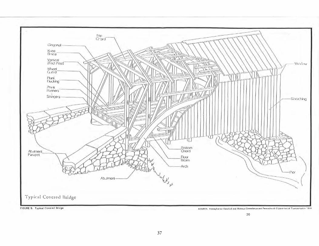
37
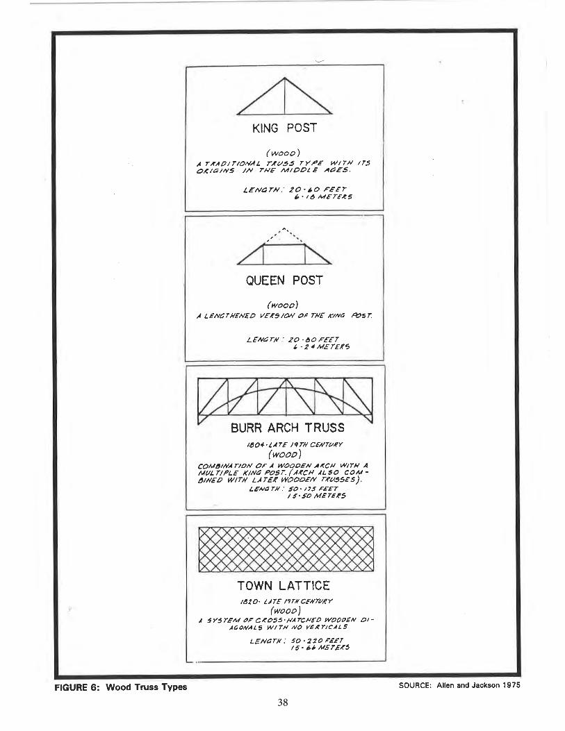
38
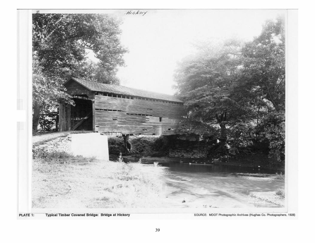
3936
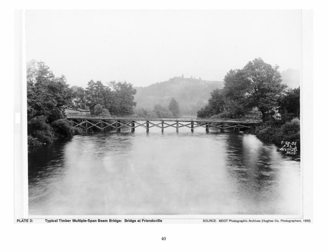
4037
41
38
an arch bridge over the Piscataqua River near Portsmouth, New Hampshire. Known locally as the "Great Arch," the arch-truss section of the 2,362-foot bridge, which spanned the navigable channel of the river, had a vertically curved floor system supported by three concentric ribs. Palmer modified the floor system of his later bridges to give them only a moderate rise, reducing the risk to life and limb (American Society of Civil Engineers 1976:152).
In the early nineteenth century, Theodore Burr (1771-1822) developed a truss-arch combination, which he patented as the Burr truss in 1817. By combining the arch with the truss form, Burr was able to increase the length of the individual spans; the arch reduced the longitudinal sag of the road surface which had constrained the span-length of the earlier beam bridges (Lay 1992:278). Burr truss bridges were constructed over many significant crossings including the crossing over the Hudson River at Waterford, New York and the Susquehanna River crossing at McCall's Ferry, Pennsylvania.
Ithiel Town (1784-1844) is credited with having designed the first true truss in America. In 1820, he designed the Town lattice truss. This truss is composed of a stiff web of closely spaced diagonal timbers. The Town truss was exceptionally strong and easy to construct, and competed well with the Burr truss. Although Town lattice truss bridges were almost exclusively made of wood, the truss became the prototype for later wood and metal truss forms.
One early successor to the lattice truss was the Long truss. Patented by Colonel Stephen Long in 1829, the Long truss was a lattice truss that was refined to its essential elements. Long calculated the stresses in each of the individual members and sized them according to the load that they would carry (Lay 1992:279).
Because the wood members of these bridge types were subject to deterioration, the majority of the timber bridges were covered with roofs and wood siding to protect against the elements. Thus the "covered bridge" became a particularly versatile early American bridge form. When properly maintained, these wood bridges could have a long service life. The most frequent causes of covered bridge failures resulted from the lack of maintenance, fires, or floods (Armstrong 1976:109).
The railroads had a significant impact on the construction as well as on the continuing popularity of the timber bridge. During the 1830s, the Baltimore and Ohio Railroad employed bridge builders such as Lewis Wernwag to construct bridges over its major crossings. Burr, Town, and Long trusses were all extensively employed and became standard for railroad-bridge construction (Waddell 1916:21).
Another type, the timber trestle bridge, also was used extensively by the railroads. The first timber trestle was built by the Philadelphia and Reading Railroad in 1840 (Waddell 1916:22). With timber in abundant supply, the railroads used this functional design as an inexpensive and practical bridge option for its lines, particularly in remote locations of the country (Plate 3).
42
39
The popularity of the timber bridge continued into the 1880s even with the ascension of iron and steel as bridge materials. The combination of timber with other materials began with the invention of the Howe truss in 1840. William Howe patented a truss which utilized iron verticals as tension members and wood diagonals as compression members. The Howe truss became a standard of railroad bridge design. By the 1860s, the problem of wood deterioration was under better control with the invention of pressure creosote treatments, which extended the life of the wood members. Timber pile bent structures remained popular, in particular in tidal areas, into the twentieth century. These were most often used in combination with concrete.
Timber bridges continued to be constructed in the United States during the twentieth century. A significant technological development of the 1930s permitted construction of timber-concrete composite structures, featuring decks utilizing both timber and reinforced concrete. The 1975 American Society of Civil Engineers Design Guide and Commentary on Wood Structures offered the following description of composite decks of timber and concrete:
Composite timber-concrete decks are commonly used in bridge construction. Construction is such that timber carries most of the tension forces. Composite construction is of two basic types, T-beams and slab decks. . . .Composite T-beam sections consist of timber stringers, which form the stem, and concrete slab for the flange area. Notches are cut into the top edge of the stringers to resist horizontal shear and mechanical fasteners are driven into the top to prevent vertical separation so that the two components perform integrally. Stresses due to temperature changes must be considered in the concrete section.
Composite slabs consist of nominal 2-inch lumber, usually nailed-laminated with the wide faces vertical, and a concrete section cast monolithically in place. Grooves are formed by using alternate laminations that differ in width by 2 inches or by fabricating panels with a 2-inch offset between laminations. Horizontal shear is resisted by grooves cut into the projecting laminations or by metal shear plates. Transverse joints in the timber portion are made by dapping or cutting alternate laminations to a different length to provide finger joints. The concrete slab should be reinforced for temperature stress and for negative bending stresses when the deck is continuous over a support. No falsework or extensive forming is necessary with this construction [American Society of Civil Engineers 1975:372-73].
The timber-concrete composite slab type of bridge construction was pioneered in the United States by James F. Seiler and the American Wood-Preservers Association between 1932 and 1935. The latter organization's 1935 patent for "composite wood and concrete construction" became the basis for such technology.
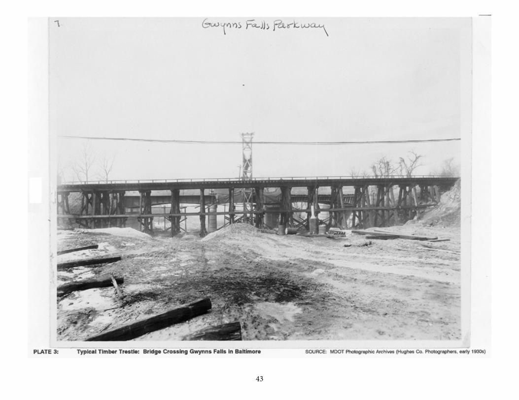
4340
44
41
TIMBER BRIDGES IN MARYLAND
Because of the availability of lumber in the state, the timber bridge was a functionally popular bridge type in Maryland from the European settlement era to the twentieth century. The numerous small streams that cross the state as well as the larger rivers such as the Susquehanna were often spanned by timber bridges during the eighteenth and nineteenth centuries.
In 1724, the Maryland General Assembly acted to clarify the rights of the counties to create and maintain bridges. The Assembly empowered county officials,
as often as need shall require, for the repairing and making of bridges over the heads of rivers, creeks, branches, swamps, or other low and miry places, to cut down, or cause to be cut down, any tree or trees growing on any of the next adjacent land to such bridges necessary to be made or repaired, and the same trees to maul, or caused to be mauled, and carried from off such adjacent lands, and applied to the making and necessary repairs of such bridges as aforesaid [Kilty 1808:November 1724 Session, Chapter 14].
Although the type of timber bridge is not specifically stated in the 1724 law, these bridges were most likely simple beam-type bridges, and king and queen post truss types, which could be constructed rapidly and cheaply over Maryland's small streams and rivers (a 1795 supplement to the 1724 act granted compensation to the owners of the trees taken by the county to construct these small bridges) (Kilty 1808:November 1795 Session, Chapter 37).
In the early nineteenth century, Maryland took advantage of the evolving bridge truss technology. The state's major river crossings attracted significant bridge builders to Maryland. In 1817-1818, Theodore Burr constructed the Rock Run Bridge, an eighteen-span, 4,170-foot, covered Burr arch truss bridge over the Susquehanna at Port Deposit. The bridge burned in 1823 and was rebuilt in 1824 by Louis Wernwag, a native of Germany who became a prominent bridge builder in the United States after his immigration in the late 1700s. Wernwag also constructed the Conowingo Bridge over the Susquehanna River at Conowingo, Maryland, in 1818. This was a seven-span, 1,334-foot, covered, highway bridge that served the local community until 1847 when it was destroyed in a spring freshet.
These bridges represent the most impressive of the covered bridges built in the state. More common, however, were the smaller covered timber bridges, such as the Roddy Road Covered Bridge over Owens Creek in Frederick County, Maryland. Constructed by an anonymous builder, this is a single-span, king-post truss bridge that has stood in its current location since circa 1850. A 1937 survey of the state's covered bridges detailed 52 covered bridges, 35 of which were extant at the time of the survey, including Burr, bowstring, queen-post and king-post truss-type bridges.
45
42
Storms, fire, development, and vandalism have reduced this number to seven known covered bridges extant in Maryland today.
Apart from covered bridges, Maryland had an abundance of small uncovered timber bridges of the timber beam and king-post and queen-post truss varieties. An 1899 statewide survey of highway bridges conducted by the Maryland Geological Survey indicated that:
a majority of the small bridges with spans up to 30 feet, culverts, and drains are of wood. The shortest spans are a simple beam to which is nailed the flooring and rails. For spans from 10 to 30 feet, a simple triangular frame with a central tension rod or post forms the supporting truss [Johnson 1899:205-206].
Many of these small bridges were replaced with metal truss and later with concrete spans, necessary for the growing traffic demands of the industrializing state.
Timber trestle-type railroad bridges were also constructed in Maryland. While constructing the more ornate and complex bridges in urban areas, the Baltimore and Ohio Railroad built the purely functional timber trestle bridges over crossings in its more rural locations. One such example is the B&O bridge over Antietam Creek constructed in about 1867. This timber trestle bridge, which is nearly 400 feet in length, was originally constructed to serve the Washington County Branch of the B&O Railroad and is believed to be the longest timber trestle built by the railroad company.
Despite the rise of use of metal and concrete in bridge building, timber bridges continued to be constructed in Maryland in the twentieth century. Many of these later timber bridges were timber and concrete composite structures favored in the flat terrain of the Tidewater region. Such timber-and-concrete composite structures were evidently introduced in Maryland by the State Roads Commission engineers, who kept abreast of early twentieth century trends in composite bridge design. In the 1937-1938 Report of the State Roads Commission, Bridge Division Chief Engineer Walter C. Hopkins acknowledged professional interest in such structures:
The bridges constructed have been varied, with miscellaneous types and of different materials. Bridges have been built of concrete, steel, timber, or stone, or combinations thereof. Careful study is given the employment of those materials most satisfactorily adapted to the structure in question. Balance, proportion and treatment that will result in simplicity, gracefulness and pleasing appearance are always considered and sought by the designer [Maryland State Roads Commission 1938:71].
The Bridge Division's earliest timber-and-concrete composite bridges were built in 1937-1938 in Tidewater Maryland. Three such bridges were constructed in Wicomico County, and one each in Calvert, St. Mary's, Queen Anne's, Kent, and
46
43
Caroline counties. Pictured in the 1937-1938 State Roads Commission report, the longest such bridge was "a timber and concrete composite bridge of twelve 20-foot spans, providing a clear roadway of 26 feet, and two 3-foot, 1-inch sidewalks, over Tony Tank Pond, on the road from Salisbury to Princess Anne near Salisbury, Wicomico County" (Maryland State Roads Commission 1938:83).
Subsequent State Roads Commission reports refer to additional timber-concrete composite bridges constructed under state authority between 1939 and 1960, primarily at Tidewater (Coastal Plain) sites on the Eastern Shore and in Southern Maryland (Maryland State Roads Commission 1939a:71, 1943:45). In 1947, Bridge Division engineers observed that "the development of the composite use of timber and concrete has permitted the design of economical structures with the general appearance from the roadway of a much more costly bridge" (Maryland State Roads Commission 1947:53).
47
43
Conclusion
The following summary statements regarding structural characteristics for timber bridges, key periods of significance for timber bridges in Maryland, and the earliestknown documented examples of timber bridges in the state are based solely ondocumentary research.
Timber beam bridges (see Plate 2) consist of timber beams supported by atimber or masonry structure. Intermediate supports may be timber pile bents, andabutments may be timber, masonry, or concrete. Railings and floor system areusually wood (as in Plate 2).
Timber trestle bridges (see Plate 3) consist of timber beams supported by asystem of high timber piers or pile bents. High timber trestles were frequently utilized as railroad bridges.
Timber covered bridges (see Figures 5 and 6 and Plate 1) consist of a structural timber truss covered by timber roofing and siding which serves to protect thestructural components from the weather. A variety of truss types were used,including king-post, queen-post, Town, and Burr. The truss systems include vertical and diagonal elements, between horizontal upper and lower elements called top and bottom chords. In the Burr arch-truss variant, a timber arch is added to providefurther structural support (see Figure 6). In the Town truss variant, also called alattice truss, the truss consists of timber members crossing at 45- to -60-degreeangles, connected with wooden pins or trunnels. Timber covered bridges oftenfeature wood plank decking supported on a system of timber stringers andfloorbeams; wheel guards and plank runners are sometimes installed on the decking.Typically, timber covered bridges are supported on masonry abutments and (if more than one span) piers.
Timber-and-concrete composite bridges include a superstructure consisting of a composite timber and concrete slab. The timber and concrete materials workintegrally to carry the deck loads. These composite decks are typically supported on timber piers or piles. Railings may be of wood or concrete.
Key periods of significance for timber bridges in Maryland, as indicated bydocumentary research include 1724 to ca. 1900, during which simple wooden beam bridges continued to be constructed by local and county authorities, in single-spanand multiple-span variants; ca. 1800 to ca. 1900, the heyday of covered bridgeconstruction in the state, including major long-span river crossings by significantbridge builders Theodore Burr and Lewis Wernwag, as well as a large number ofsmaller timber covered bridges built with different truss configurations (simple king-post and Burr arch-truss are known to have been utilized); ca. 1840 to 1900, theperiod when large timber trestles for railroad use predominated; and ca. 1935 to
48
44
1960, the era of development and use of timber-concrete composite bridges by theState Roads Commission in the Tidewater or Coastal Plains region of Maryland.
The earliest known documented examples of timber bridges in Maryland arethose referenced in the 1724 Act of the General Assembly concerning the cutting of timber for bridge construction. The earliest known documented covered timberbridges built in Maryland are the Susquehanna River long-span covered bridgesconstructed in 1818 by significant bridge builders Theodore Burr and LewisWernwag. Dating of the earliest timber trestles built in the state cannot be exactlystated, but documentary sources indicate that during the 1840s Maryland railroadssuch as the Baltimore and Ohio and the Northern Central erected trestles. Theearliest known documented timber-and-concrete composite bridges in the state were eight such structures erected by the State Roads Commission in Tidewater (Coastal Plain) locations in 1937-1938. (According to the 1993 State Highway BridgeInventory, seven of these structures are extant.
49
45
HISTORICAL DEVELOPMENT
The stone arch bridge represents one of the earliest recorded advances in bridge building, illustrating the movement from simple beam spans to use of the structural arch form to better support loads. Engineering historians have traced the first functional precursors of stone arch bridges to the so-called corbelled arch, utilized in ancient cultures. The corbelled arch consists of masonry blocks built over a wall opening by uniformly advancing courses from each side until they meet at a midpoint. No actual arch action is produced by this design, also often called a false arch (Pennsylvania Historical and Museum Commission, and Pennsylvania Department of Transportation 1986:A-5).
Since a true arch cannot support itself until the keystone is properly in place, the construction of stone arches required temporary support of the entire structure on falsework, usually composed of a scaffolded timber framework. Stone arch construction utilizing circular arches with keystones, and falsework during construction, was perfected by the ancient Romans, and the basic, necessary technology thereafter remained largely unchanged for two thousand years. Improvements between Roman times and the seventeenth century primarily consisted of efforts to achieve a greater span-to-rise ratio (that of the typical circular Roman arch was 2:1); for nearly 400 years after its 1345 construction, Florence's Ponte Vecchio with its "flat" (high span-to-rise ratio) trio of arches held the record for highest span-to-rise ratio (Lay 1992:267-268).
Coming from a tradition of craftsman design, the stone arch bridge owed its remarkable historical persistence to its load-carrying strength, its relatively simple construction technique, and its long life (Figure 7). The stones utilized in a stone arch bridge may consist of rubble masonry (rough unfinished and untooled stones), squared masonry (stones which have been tooled to a rectangular shape and roughly finished), and ashlar masonry (squared stones given a further tooling to a more refined finish). Construction of the substructure (piers and abutments from which the arch is said to "spring") was first accomplished, followed by the initial building of the "arch ring" (the basic ring composed of adjacent, usually wedge-shaped stones, or voussoirs, arranged in a radiating circle or ellipse) on the temporary system of wood falsework. With the arch rings in place across the intended width of a span (the rings together comprising the arch "barrel"), the remainder of the structure, including spandrel walls built on the arch at its outermost edges, could then be erected. Fill composed of dry earth or ballast was usually consolidated on top of the arch barrel for stability and was contained within the solid spandrel walls (P.A.C. Spero & Company 1991:13-14).
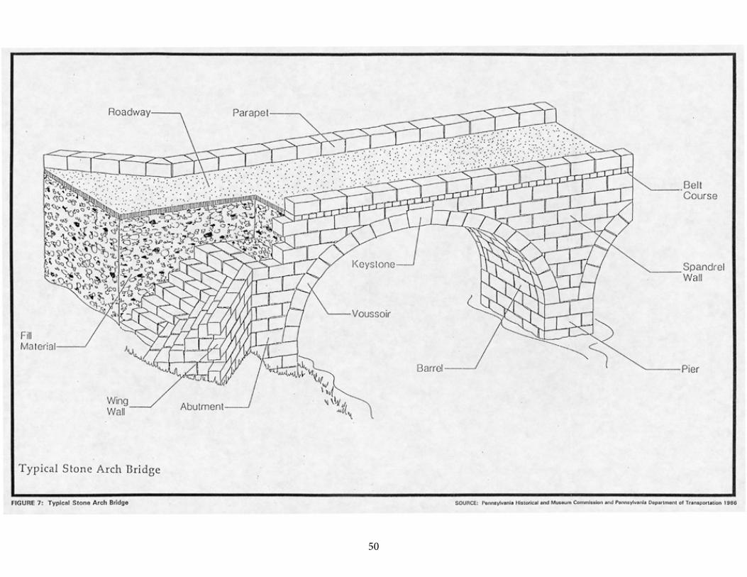
50
48
51
49
Arch bridges constructed of stone have included small bridges and culverts, as well as larger and longer multiple-span viaducts and aqueducts. Perhaps because the technology of arch construction was received rather than invented in the United States, bridge historian J.A.L. Waddell noted in his 1916 Bridge Engineering that "stone arch bridges have played a very small part in bridge evolution in America" (Waddell 1916:28). More recently, Carl Condit found that arch bridges of stone were "extremely rare" in the American colonies and that hardly any evidence of seventeenth century stone arch bridges existed (P.A.C. Spero & Company 1991:13). Legislation of the colonial period has survived indicating that colonial authorities (including Maryland's General Assembly of 1699) encouraged "good and substantial" bridges, but these may well have generally been of timber, a more readily available and less costly material than building stone in many parts of colonial America. The earliest extant datable examples of stone arch bridges in the United States are the Frankford Avenue Bridge, a three-span bridge constructed in 1697 on the King's Highway over Pennypack Creek near Philadelphia, and the Choate Bridge, a two-span structure built in 1764 at Ipswich, Massachusetts (Pennsylvania Historical and Museum Commission, and Pennsylvania Department of Transportation 1986:43; DeLony 1993:5).
Beginning in the late eighteenth century and continuing through much of the nineteenth century, the construction of stone arch bridges in the United States was given impetus by the internal improvements movement that spawned such ambitious engineering projects as turnpikes, canals, railroads, and water supply systems for rapidly growing cities. Turnpiking an existing road or properly building a new turnpike included plans for reliable stream and river crossings and a durable road surface of stone or gravel. Thus, the wealth of turnpikes built in the eastern United States between 1790 and 1840 often included improved bridges of stone to replace ferries or earlier simple wooden spans.
Canals required a variety of bridge structures, including short spans to carry the towpath from one side to the other at tight places, and culverts and aqueducts to take the canal itself over rivers and roads running transverse to its right-of-way. Lastly, the development and remarkable success of railroads in the nineteenth and early twentieth centuries inspired professional engineering interest in the design and erection of masonry structures that could effectively withstand the unprecedented heavy moving loads of locomotives and freight trains. Early large stone arch bridges constructed for railroad use, including Maryland's historic Carrollton and Thomas viaducts, dramatically illustrated the great strength inherent in the arch form. So, too, did the humbler stone culverts, often constructed to standard plans by railroads in the late nineteenth century.
The majority of surviving stone arch bridges and culverts in the United States are thus, historically linked to a turnpike, canal, or railroad of the 1800-1900 period (Plate 4). Private turnpike companies expended considerable capital building masonry arch bridges under the direction of experienced masons, but regular maintenance was not always adequately provided, and problems developed

52
50
ranging from deterioration of parapet walls to bulging of spandrel walls due to accumulating moisture in the earth fill. Generally, the arches built for canal and railroad bridges were more likely than turnpike bridges to be designed by trained engineers. Stone masonry arch construction, frequently involving use of dressed masonry, was popular for railroads such as the B&O and the Pennsylvania Railroad even after the versatility of the metal truss bridge had been demonstrated in the latter half of the nineteenth century. Older turnpike bridges, however, attracted engineers' attention after the coming of the automobile and truck forced county, state, and municipal officials to provide for the heavy traffic demands of the twentieth century. Many such bridges were destroyed or seriously altered, but others continued in use or were bypassed and remained standing.
Though one of the most ancient bridge types, the stone arch bridge made a distinctly modern contribution to the development of concrete bridge technology. The stone masonry arch provided the precedent for arches constructed first in plain or unreinforced concrete, then later in concrete reinforced with metal sections, rods, or bars which resisted the tensile forces. Although few stone arches were built after the first several decades of the twentieth century, the persistence of the arch as built in the more plastic material, concrete, was due in large measure to the demonstrated advantages of stone masonry construction, as shown in numerous turnpike bridges and railroad spans.
53
50
STONE ARCH BRIDGES IN MARYLAND
Although no datable seventeenth or eighteenth century stone arch bridges inMaryland are known, the 1699 Act of the General Assembly requiring "good andsubstantiall" bridges over all heads of creeks and rivers may have occasionedconstruction of stone bridges as well as timber bridges, since the basic technologyof stone arches was well known by that time (Browne 1902:475-476). The earliest legislative reference to arch bridges was the 1794 law which specified that common laborers hired by the county courts should not be permitted to superviseconstruction of "framed or arched" bridges over 15 feet in length (Kilty1808:November 1794 Session, Chapter 52). This law, however, clearly indicatedthat the stone arch bridge was a familiar and important bridge type in early national, and probably colonial, Maryland.
The advent of turnpikes in the state, pursuant to an 1804-1805 lawincorporating Maryland's first private toll road companies, spurred construction ofstone arch bridges for important crossings where simple timber beam structuresmight be likely to wash out or deteriorate under heavy wagon traffic. Aquestionnaire sent out to major Maryland turnpike officers in 1818 under authorityof the General Assembly and Governor Charles Goldsborough elicited evidencethat the Baltimore and Reisterstown Turnpike Company had built many bridges "of solid materials," while the Baltimore and Frederick Turnpike Company had by thattime expended over $56,000 on constructing the four-span stone bridge over theMonocacy just southeast of Frederick (this 1808 bridge, known as the "Jug Bridge," stood until 1942). The Baltimore and York Turnpike Company had built five one-span and two-span stone arch bridges on its improved "York Road," including theoldest extant datable stone arch bridge in Maryland, the Parkton Stone Arch(Goldsborough 1818). The Lloyd family of Chambersburg, Pennsylvania, and their various associated masons, dominated construction of the early nineteenth century stone arch highway bridges of Washington County; James Lloyd also is recordedas builder of the B&O's pioneering Carrollton Viaduct of 1829 (Mish andCottingham 1977; Schodek 1987:77-78).
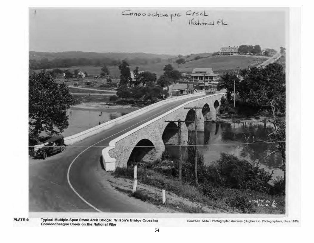
5451
55
52
Between 1811 and 1825, the federally built National Road also wasconstructed through Maryland between Cumberland and Uniontown, Pennsylvania. This landmark early federal public works project involved design and construction of numerous small-span arch culverts and a number of significant large bridges, such as the 1813 Casselman River Arch. Simultaneously, the Maryland legislaturesponsored numerous extensions to the Baltimore and Frederick Turnpike with theobject of connecting eastern and central Maryland to the National Road atCumberland. The 1818 Wilson's Bridge and other early structures among theapproximately 30 significant stone arch bridges known to have been built inWashington County were erected on these turnpikes linking Baltimore andFrederick with Cumberland and points west (Mish and Cottingham 1977).
Major canal projects, such as the Chesapeake and Ohio Canal (1828-1924)and the Chesapeake and Delaware Canal (begun 1824), also inspired construction of stone arch culverts and several large aqueducts to carry the canals overintervening streams and rivers. Perhaps the greatest impetus to stone arch bridge construction in Maryland, however, occurred with the founding and expansion of the Baltimore and Ohio Railroad during the 1820s and 1830s. During that period under the guidance of such distinguished engineers as Benjamin H. Latrobe, Jr., andJonathan Knight, the B&O first erected near Baltimore its nationally significantCarrollton Viaduct (earliest stone arch railroad bridge in the nation), followed thiswith construction of other early stone arch railway spans at Ilchester and EllicottCity (Patterson and Oliver Viaducts, each now only partially extant), and climaxedits initial expansion toward Washington with the design and erection of the extantThomas Viaduct in 1835, an imposing eight-span Roman arch structure that wasthe first multiple-span railroad viaduct and the first to be built on a horizontal curve (Harwood 1979).
The initial B&O building campaign also involved construction of numerous, less prominent stone arch culverts. A second major building campaign, between thelate 1890s and 1910 under former Pennsylvania Railroad Chief Engineer LeonorLoree, resulted in the erection of a second generation of stone arch culverts andviaducts, many of which appear to be extant based on historical research and prior Maryland Historical Trust historic resource survey forms prepared by county historic preservation officers in the counties through which the B&O passed. During thenineteenth century and the early twentieth century, the growing city of Baltimorealso engaged in construction of many stone arch spans for culverts and bridges. In 1866, the City Commissioner suggested construction of a stone bridge to carryMadison Street and three years later, reported erection of a "substantial" 40-footstone bridge on Wilkens Avenue over Gwynns Run (City of Baltimore, CityCommissioner 1866:250; 1869:376). In 1901-1902, the city built the presentBoston Street Bridge, a masonry arch constructed of brick, to carry heavily traveled Boston Street and a railroad from the industrial district of Canton (Baltimore CityChief Engineer 1902).
56
53
The Good Roads movement of the late nineteenth and early twentiethcenturies in Maryland fostered renewed interest in the preservation of the olderstone arch highway bridges of the state, many of which had fallen into disrepair.The 1899 comprehensive report of the Highway Division of the MarylandGeological Survey noted how stone arch deterioration had been caused by "theweather and in part by willful destruction." Moisture penetrating the bridges oftenfroze, causing "with the frost, a perceptible bulging and cracking of the walls." The 1899 report noted the four-arch "Jug Bridge" over the Monocacy as an example of such bulging problems, and observed that the parapet walls of the CasselmanRiver Arch and the Cabin John Aqueduct Bridge were both in decayed condition(Johnson 1899:206-207). After purchasing nearly 190 miles of old turnpike right-of-way in 1910 and 1911, the State Roads Commission implemented a program tobegin "the saving of the old stone arches and similar structures existing on theseformer turnpikes," noting that many of the bridges were "important and valuableboth physically and historically" (Maryland State Roads Commission 1912b:80).Between 1908 and 1911, the State Roads Commission acted to save those bridges "most likely to fail and to permit probably the saving of all the rest" (Maryland State Roads Commission 1912b:80).
Maryland's historic stone arch bridges include a range of outstanding extantexamples, reflecting primarily the early nineteenth century emphasis on thedevelopment of turnpikes, canals, and railroads for the state. Among the bridgesare a number that are nationally significant, such as the 1813 Casselman Riverstone arch on the National Road, the 1829 Carrollton Viaduct on the old main lineof the Baltimore and Ohio Railroad, and the 1835 Thomas Viaduct on theWashington Branch of the same railroad. A large number of stone arch turnpikebridges, both single-span and multiple-span, have also survived. Many originalstone arch bridges and aqueducts likewise exist along the right-of-way of theChesapeake and Ohio Canal, and there is also a historic resource of nationalimportance in the Cabin John Aqueduct (or Union Bridge), a Roman arch built inthe 1857-1864 period by the federal government for the Washington water supplysystem in the midst of the Civil War. A concise description of the major types ofsignificant stone arch bridges found in Maryland, with some discussion of specificexamples, serves to document the state's remarkable built heritage in this bridgeform.
57
54
Stone Arch Roadway and Turnpike Bridges
Historical research has located no evidence of any extant, or non-extant but documented, stone arch bridges built in Maryland during the seventeenth and eighteenth centuries. Maryland's surviving nineteenth century stone arch highway or turnpike bridges include a group of some 24 (as of 1977) significant bridges in Washington County (out of an estimated 30 actually constructed between 1818 and 1863). The concentration of such bridges in Washington County (in the group is the famous Burnside Bridge, a key, famous point in the Civil War Battle of Antietam) has inspired considerable historical study, including Helen Ashe Hays's 1910 regional classic The Antietam and Its Bridges and a 1965 photo exhibit at the courthouse in Hagerstown (Hays 1910; Mish and Cottingham 1977). Significant stone arch turnpike bridges also were built in other Maryland counties. The oldest documented stone arch bridge in Maryland is the Parkton stone arch, a two-span masonry bridge over the Little Gunpowder Falls, built in 1809 for the Baltimore and York Turnpike. The state's second-oldest stone arch turnpike bridge that has been securely dated is the Casselman River Arch, erected in 1813 on the National Road near Grantsville (Little Crossings Historical Committee 1964).
The design characteristics of Maryland's extant historic stone arch bridges vary in number of spans, shape of piers and parapets, rise-to-span ratio, type of stone employed (brick was also utilized in some cases), and in the treatment of the masonry (coursed rubble, squared, or ashlar). Based on historical research and prior survey forms, the following are descriptions of some representative known stone arch bridges built for turnpikes, the National Road, and private or municipal roads in Maryland:
Parkton Stone Arch: Maryland Route 463 (old Baltimore and York Turnpike) over Little Gunpowder Falls, Baltimore County (MHT-BA-593). Built in 1809 and the oldest surviving, dated stone arch bridge in Maryland. Two arch spans, each 18 feet long. Central pier 6 feet thick and abutments 8 feet thick. Built in 1809 for the Baltimore and York Turnpike, one of the first group of turnpikes chartered by the state. Attributed to John Davis (1770-1864), clerk of Philadelphia Waterworks and first superintendent of Baltimore Water Company.
Casselman River Arch: Old Route 40 (National Road) over Casselman River, near Grantsville, Garrett County (MHT-G-II-C-023). Built in 1813 for the National Road, the first improved turnpike built by the federal government. 354-foot-long bridge built of uncoursed masonry, with single arch span. At time of construction, the largest single-span arch bridge in the United States. The distinctive "humpbacked" shape of the bridge provided better drainage for the roadway. Repaired in 1911 with six steel supporting columns; remained in service until 1933. Recognized as National Historic Landmark (1964).
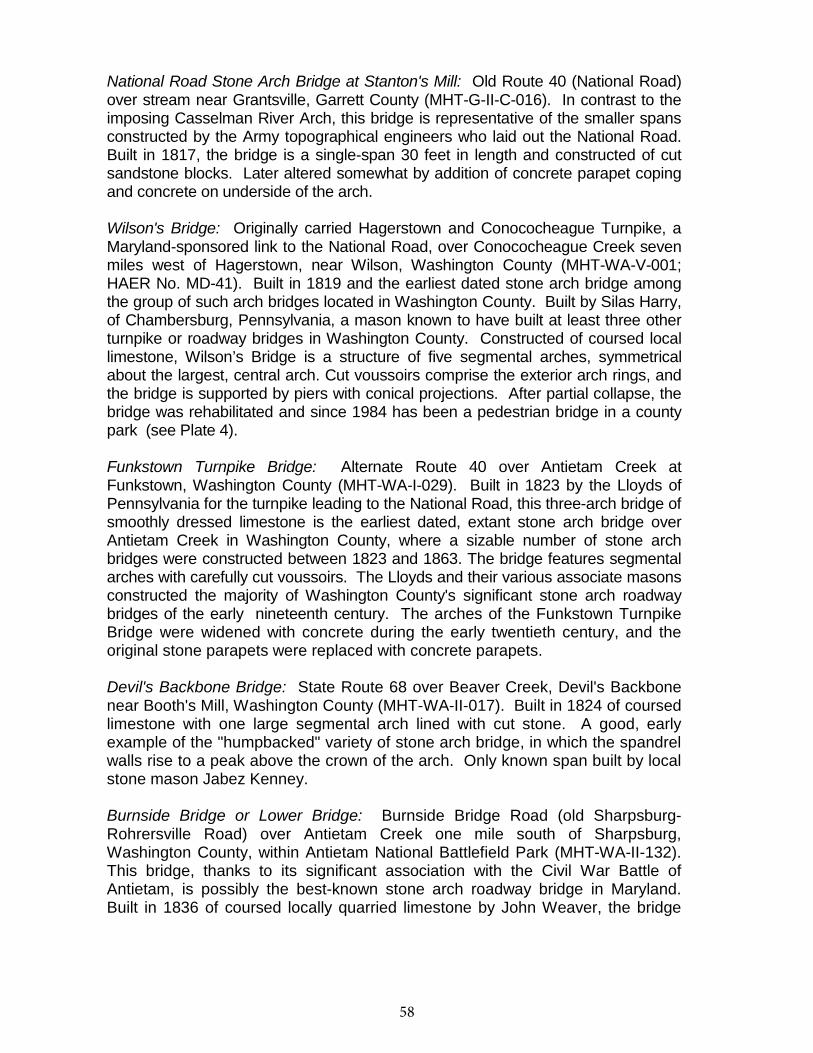
58
55
National Road Stone Arch Bridge at Stanton's Mill: Old Route 40 (National Road) over stream near Grantsville, Garrett County (MHT-G-II-C-016). In contrast to the imposing Casselman River Arch, this bridge is representative of the smaller spans constructed by the Army topographical engineers who laid out the National Road. Built in 1817, the bridge is a single-span 30 feet in length and constructed of cut sandstone blocks. Later altered somewhat by addition of concrete parapet coping and concrete on underside of the arch.
Wilson's Bridge: Originally carried Hagerstown and Conococheague Turnpike, a Maryland-sponsored link to the National Road, over Conococheague Creek seven miles west of Hagerstown, near Wilson, Washington County (MHT-WA-V-001; HAER No. MD-41). Built in 1819 and the earliest dated stone arch bridge among the group of such arch bridges located in Washington County. Built by Silas Harry, of Chambersburg, Pennsylvania, a mason known to have built at least three other turnpike or roadway bridges in Washington County. Constructed of coursed local limestone, Wilson’s Bridge is a structure of five segmental arches, symmetrical about the largest, central arch. Cut voussoirs comprise the exterior arch rings, and the bridge is supported by piers with conical projections. After partial collapse, the bridge was rehabilitated and since 1984 has been a pedestrian bridge in a county park (see Plate 4).
Funkstown Turnpike Bridge: Alternate Route 40 over Antietam Creek at Funkstown, Washington County (MHT-WA-I-029). Built in 1823 by the Lloyds of Pennsylvania for the turnpike leading to the National Road, this three-arch bridge of smoothly dressed limestone is the earliest dated, extant stone arch bridge over Antietam Creek in Washington County, where a sizable number of stone arch bridges were constructed between 1823 and 1863. The bridge features segmental arches with carefully cut voussoirs. The Lloyds and their various associate masons constructed the majority of Washington County's significant stone arch roadway bridges of the early nineteenth century. The arches of the Funkstown Turnpike Bridge were widened with concrete during the early twentieth century, and the original stone parapets were replaced with concrete parapets.
Devil's Backbone Bridge: State Route 68 over Beaver Creek, Devil's Backbone near Booth's Mill, Washington County (MHT-WA-II-017). Built in 1824 of coursed limestone with one large segmental arch lined with cut stone. A good, early example of the "humpbacked" variety of stone arch bridge, in which the spandrel walls rise to a peak above the crown of the arch. Only known span built by local stone mason Jabez Kenney.
Burnside Bridge or Lower Bridge: Burnside Bridge Road (old Sharpsburg-Rohrersville Road) over Antietam Creek one mile south of Sharpsburg, Washington County, within Antietam National Battlefield Park (MHT-WA-II-132). This bridge, thanks to its significant association with the Civil War Battle of Antietam, is possibly the best-known stone arch roadway bridge in Maryland. Built in 1836 of coursed locally quarried limestone by John Weaver, the bridge
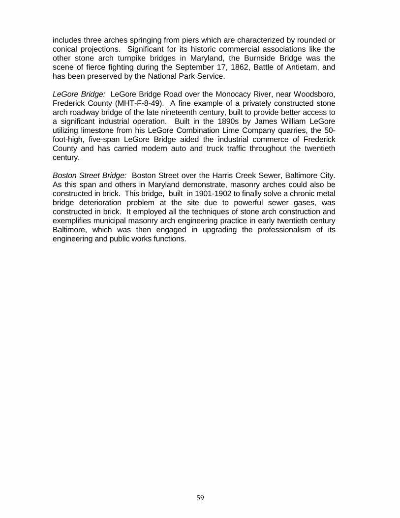
59
56
includes three arches springing from piers which are characterized by rounded or conical projections. Significant for its historic commercial associations like the other stone arch turnpike bridges in Maryland, the Burnside Bridge was the scene of fierce fighting during the September 17, 1862, Battle of Antietam, and has been preserved by the National Park Service.
LeGore Bridge: LeGore Bridge Road over the Monocacy River, near Woodsboro, Frederick County (MHT-F-8-49). A fine example of a privately constructed stone arch roadway bridge of the late nineteenth century, built to provide better access to a significant industrial operation. Built in the 1890s by James William LeGore utilizing limestone from his LeGore Combination Lime Company quarries, the 50-foot-high, five-span LeGore Bridge aided the industrial commerce of Frederick County and has carried modern auto and truck traffic throughout the twentieth century.
Boston Street Bridge: Boston Street over the Harris Creek Sewer, Baltimore City. As this span and others in Maryland demonstrate, masonry arches could also be constructed in brick. This bridge, built in 1901-1902 to finally solve a chronic metal bridge deterioration problem at the site due to powerful sewer gases, was constructed in brick. It employed all the techniques of stone arch construction and exemplifies municipal masonry arch engineering practice in early twentieth century Baltimore, which was then engaged in upgrading the professionalism of its engineering and public works functions.
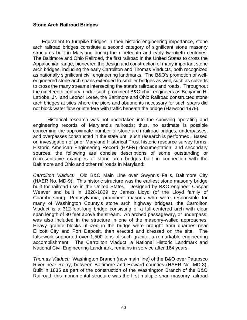
60
56
Stone Arch Railroad Bridges
Equivalent to turnpike bridges in their historic engineering importance, stonearch railroad bridges constitute a second category of significant stone masonrystructures built in Maryland during the nineteenth and early twentieth centuries.The Baltimore and Ohio Railroad, the first railroad in the United States to cross the Appalachian range, pioneered the design and construction of many important stonearch bridges, including the early Carrollton and Thomas Viaducts, both recognized as nationally significant civil engineering landmarks. The B&O's promotion of well-engineered stone arch spans extended to smaller bridges as well, such as culverts to cross the many streams intersecting the state's railroads and roads. Throughout the nineteenth century, under such prominent B&O chief engineers as Benjamin H. Latrobe, Jr., and Leonor Loree, the Baltimore and Ohio Railroad constructed stone arch bridges at sites where the piers and abutments necessary for such spans did not block water flow or interfere with traffic beneath the bridge (Harwood 1979).
Historical research was not undertaken into the surviving operating andengineering records of Maryland's railroads; thus, no estimate is possibleconcerning the approximate number of stone arch railroad bridges, underpasses,and overpasses constructed in the state until such research is performed. Based on investigation of prior Maryland Historical Trust historic resource survey forms, Historic American Engineering Record (HAER) documentation, and secondarysources, the following are concise descriptions of some outstanding orrepresentative examples of stone arch bridges built in connection with theBaltimore and Ohio and other railroads in Maryland:
Carrollton Viaduct: Old B&O Main Line over Gwynn's Falls, Baltimore City(HAER No. MD-9). This historic structure was the earliest stone masonry bridge built for railroad use in the United States. Designed by B&O engineer CasparWeaver and built in 1828-1829 by James Lloyd (of the Lloyd family ofChambersburg, Pennsylvania, prominent masons who were responsible formany of Washington County's stone arch highway bridges), the CarrolltonViaduct is a 312-foot-long bridge consisting of a full-centered arch with clearspan length of 80 feet above the stream. An arched passageway, or underpass, was also included in the structure in one of the masonry-walled approaches.Heavy granite blocks utilized in the bridge were brought from quarries nearEllicott City and Port Deposit, then erected and dressed on the site. Thefalsework supported over 1,500 tons of such granite, a remarkable engineeringaccomplishment. The Carrollton Viaduct, a National Historic Landmark andNational Civil Engineering Landmark, remains in service after 164 years.
Thomas Viaduct: Washington Branch (now main line) of the B&O over Patapsco River near Relay, between Baltimore and Howard counties (HAER No. MD-3).Built in 1835 as part of the construction of the Washington Branch of the B&ORailroad, this monumental structure was the first multiple-span masonry railroad
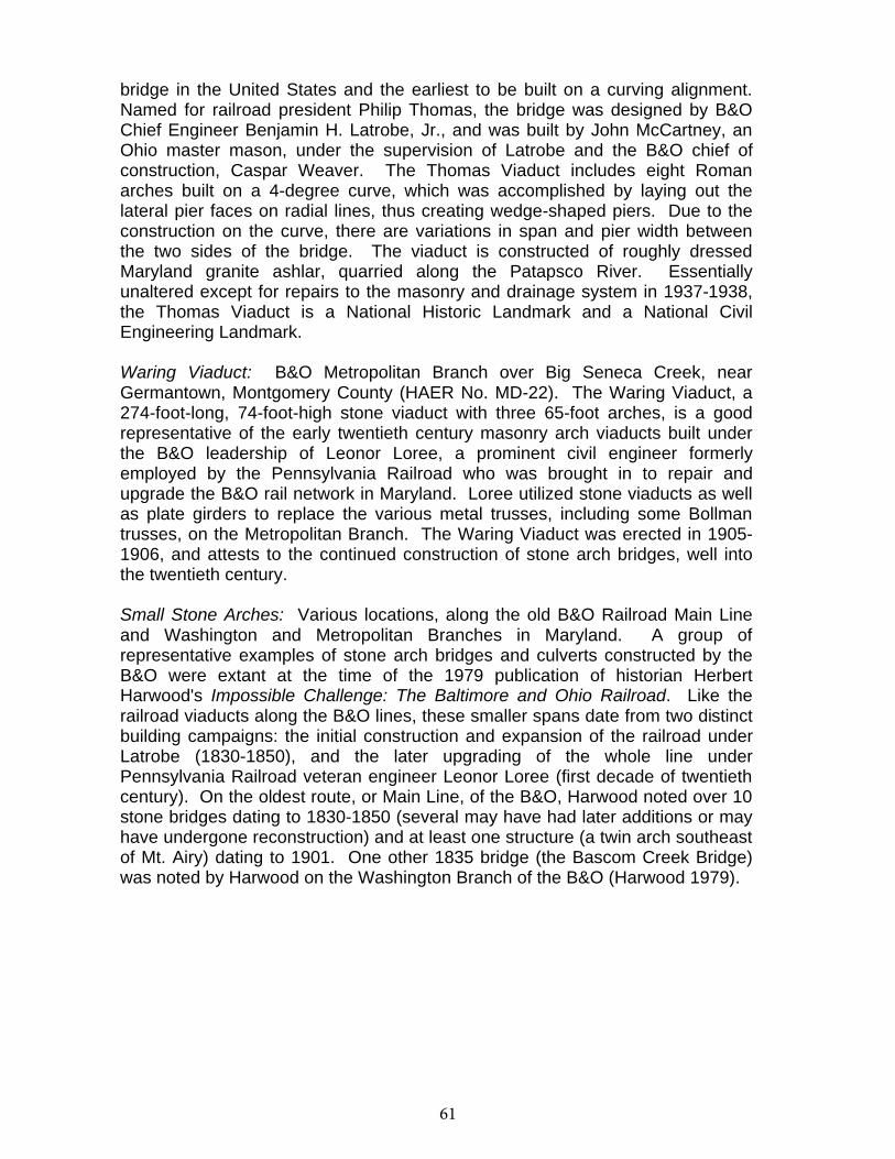
61
57
bridge in the United States and the earliest to be built on a curving alignment.Named for railroad president Philip Thomas, the bridge was designed by B&OChief Engineer Benjamin H. Latrobe, Jr., and was built by John McCartney, anOhio master mason, under the supervision of Latrobe and the B&O chief ofconstruction, Caspar Weaver. The Thomas Viaduct includes eight Romanarches built on a 4-degree curve, which was accomplished by laying out thelateral pier faces on radial lines, thus creating wedge-shaped piers. Due to theconstruction on the curve, there are variations in span and pier width betweenthe two sides of the bridge. The viaduct is constructed of roughly dressedMaryland granite ashlar, quarried along the Patapsco River. Essentiallyunaltered except for repairs to the masonry and drainage system in 1937-1938,the Thomas Viaduct is a National Historic Landmark and a National CivilEngineering Landmark.
Waring Viaduct: B&O Metropolitan Branch over Big Seneca Creek, nearGermantown, Montgomery County (HAER No. MD-22). The Waring Viaduct, a274-foot-long, 74-foot-high stone viaduct with three 65-foot arches, is a goodrepresentative of the early twentieth century masonry arch viaducts built underthe B&O leadership of Leonor Loree, a prominent civil engineer formerlyemployed by the Pennsylvania Railroad who was brought in to repair andupgrade the B&O rail network in Maryland. Loree utilized stone viaducts as wellas plate girders to replace the various metal trusses, including some Bollmantrusses, on the Metropolitan Branch. The Waring Viaduct was erected in 1905-1906, and attests to the continued construction of stone arch bridges, well intothe twentieth century.
Small Stone Arches: Various locations, along the old B&O Railroad Main Lineand Washington and Metropolitan Branches in Maryland. A group ofrepresentative examples of stone arch bridges and culverts constructed by theB&O were extant at the time of the 1979 publication of historian HerbertHarwood's Impossible Challenge: The Baltimore and Ohio Railroad. Like therailroad viaducts along the B&O lines, these smaller spans date from two distinctbuilding campaigns: the initial construction and expansion of the railroad underLatrobe (1830-1850), and the later upgrading of the whole line underPennsylvania Railroad veteran engineer Leonor Loree (first decade of twentiethcentury). On the oldest route, or Main Line, of the B&O, Harwood noted over 10 stone bridges dating to 1830-1850 (several may have had later additions or mayhave undergone reconstruction) and at least one structure (a twin arch southeast of Mt. Airy) dating to 1901. One other 1835 bridge (the Bascom Creek Bridge)was noted by Harwood on the Washington Branch of the B&O (Harwood 1979).
62
58
Other Significant Stone Arch Bridges
Other known stone arch bridges constructed in Maryland include a varietyof structures built for the Chesapeake and Ohio Canal during the nineteenthcentury, and a singularly significant Roman arch, the Cabin John Aqueduct(Union Bridge), built between 1857 and 1864 by the federal government for theWashington, D.C., water system. In different ways, these structures display thetraditional characteristics of stone arch bridge construction, adapted to meet thechallenge of a large, engineered public works project.
To carry streams under the canal bed, more than 200 stone arch culvertswere built along the right-of-way of the C&O Canal, between 1828 and its 1924closing. While most such culverts were at right angles to the canal, a minority of such culverts were constructed at a skew angle to the canal bed, which required an innovative rifled construction of the arch rings comprising the barrel of thearch. Built in 1832, Culvert 65, documented as HAER No. MD-32, is an example of the skewed construction of C&O canal culverts. The canal also required larger aqueducts at river and major creek crossings; these, too, were arch structuressupporting the canal itself above the river or stream (Sanderlin 1964). InWashington County alone, C&O engineers built five notable aqueducts between1832 and 1840 (Mish and Cottingham 1977). Two of the most notable were theConococheague Aqueduct at Williamsport, a three-span arch structure with piers on rounded footings and crowned at the parapet with decorative capitals, and the Licking Creek Aqueduct, featuring only one arch but with a total structure lengthof over 120 feet. Since the creation of the Chesapeake and Ohio Canal National Park in the 1950s, extant and partially demolished C&O canal culverts andaqueducts have been in the care of the National Park Service. Similar culvertswere constructed on the lower-lying Chesapeake and Delaware canal, but thesewere destroyed during the twentieth century transformation of that canal into aship canal (Gray 1985).
Another stone arch bridge of national historic engineering significance inMaryland is the Cabin John Aqueduct or Bridge, also known as the Union Arch or Bridge. This remarkable Roman arch was built between 1857 and 1864 underthe direction of Army engineer Montgomery C. Meigs, also responsible for theU.S. Capitol dome. After surveys authorized by Congress, Meigs in 1853recommended a water supply plan for growing Washington which involvedmoving water from the Potomac River above Great Falls in Maryland. Meigspersuaded officials to fund construction of a massive conduit capable ofsupplying the city with over four times the water furnished at the time to Paris.To avoid loss of head in the pipe as it crossed the valley of the Cabin JohnBranch, a Potomac tributary, Meigs designed and built an arch bridge 450 feetlong to carry it, with a single flat arch span of 220 feet and a 57.25-foot rise.Running between its solid spandrel walls, the bridge contained a brick conduit 9feet in diameter. The structure has a bottom arch of radially layered, cut and
63
59
dressed granite, and inner rings of radially layered sandstone, the materialutilized on the remainder of the bridge. Hidden behind the solid sandstone side walls, the actual, structural spandrel walls of the bridge consist of arches (five on the west end, four on the east), which reduce the dead-load weight of thestructure on the haunches (Schodek 1987:112-114).
The Cabin John Bridge or Aqueduct continues to furnish water to theDistrict of Columbia, and also carries MacArthur Boulevard over Cabin JohnBranch and the twentieth century George Washington Memorial Parkway. Thestructure also once carried a railway (Trautwine 1872:343). The bridge is aNational Historic Landmark and a National Civil Engineering Landmarkdesignated by the American Society of Civil Engineers (Schodek 1987:112-114).
64
59
Conclusion
The following summary statements regarding structural characteristics forstone arch bridges, key periods of significance for stone arch bridges inMaryland, and the earliest known documented examples of stone arch bridges in the state are based solely on documentary research.
Stone arch bridges (see Figure 7 and Plate 4) consist of a masonry archbarrel or ring, on the outermost edges of which are built spandrel walls whichserve as retaining walls to contain the fill material (rubble, large rocks, or dry soil) deposited over the arch. The arch, which is in compression, carries the loadstransmitted by the deck and spandrel walls. The spandrel walls typically extendabove the roadway deck level to form the parapet walls of the bridge; a beltcourse, flush with or projecting from the spandrel wall, may give greater definition to the parapet. The arch ring is frequently articulated by voussoirs, or wedge-shaped cut stones (the center voussoir, called the keystone, is often givengreater architectural treatment). Stone arch bridges may also include a datestone placed within the parapet. Typical substructural supports include masonryabutments and wingwalls, and masonry piers (if the bridge is a multiple-spanstructure). Numerous stylistic variations are possible in form and treatment ofmaterials.
Key periods of significance for stone arch bridges in Maryland, asindicated by documentary research, include 1790-1830, the era in which stonearch turnpike and National Road bridges were first built in the state; 1825-1850,the period when the B&O Railroad and other Maryland railroads initially utilizedstone arches, including the B&O's nationally significant Carrollton Viaduct (1829) and Thomas Viaduct (1835); and 1850-1910, during which railroads continuedtheir use of stone arch spans, and such bridges enjoyed expanded use on theroads of the Piedmont and Appalachian Plateau regions of Maryland. Between1828 and 1924, stone arch canal bridges and aqueducts were also constructedfor the C&O Canal.
The earliest known documented examples of stone arch bridges inMaryland are the 1809 Parkton Stone Arch (Bridge #3105), the 1813 Casselman River Arch on the National Road, and the 1818-1819 Wilson's Bridge overConococheague Creek. A known significant grouping of turnpike-related stonearch bridges has been identified in Washington County; these bridges (includingWilson's Bridge) comprise a group built between 1818 and 1860. (Burnside'sBridge on the Antietam, built 1836, also is nationally significant for its association with the 1862 Battle of Antietam.) Other historically significant extant stone arch bridges in Maryland include the 1829 Carrollton Viaduct, the 1835 ThomasViaduct, and the Cabin John Aqueduct, or Union Bridge, built 1857-1864.
65
61
SECTION V: METAL TRUSS BRIDGES
HISTORICAL DEVELOPMENT
Truss bridges built in either iron or steel constitute a large number of Maryland's known historic bridges. These bridges, designed and constructed in a wide variety of types during the nineteenth and twentieth centuries, are among the most familiar historic bridges in the state. The type is widely recognized, taking second place only to timber-covered bridges and stone arch spans in their attractiveness to feature writers for newspapers and magazines. Metal truss bridges possess a significant technological history directly reflecting the evolution of Maryland's transportation network.
Prominent American highway and bridge engineer Milo S. Ketchum in his 1908 work The Design of Highway Bridges and the Calculation of Stresses in Bridge Trusses offered the following, succinct definition of a truss bridge:
A truss is a framework composed of individual members so fastened together that loads applied at the joints produce only direct tension or compression. The triangle is the only geometrical figure in which the form is changed only by changing the lengths of the sides. In its simplest form every truss is a triangle or a combination of triangles. The members of the truss are either fastened together with pins, pin-connected, or with plates and rivets, riveted [Ketchum 1908:1].
Whereas a simply supported beam bridge spanning between abutments is subject to direct bending, with one structural member carrying both compressive and tensile stresses, the members of a truss individually carry only tensile or compressive stresses. The distribution of tensile (pulling a member apart) and compressive (pushing a member together) forces varies with the many types of trusses (Figures 8 through 11; Plate 5).
As presented in the Timber Bridges section of this report, construction of truss bridges in the United States originally began in the late eighteenth century utilizing timber as the basic building material. Renaissance architect Andrea Palladio's pioneering discussion of trusses was translated and circulated here as early as the 1740s, while in Europe during the late 1700s such innovative builders as the Grubenmanns erected covered wooden truss bridges in mountainous areas (Pennsylvania Historical and Museum Commission, and Pennsylvania Department of Transportation 1986:109-126).
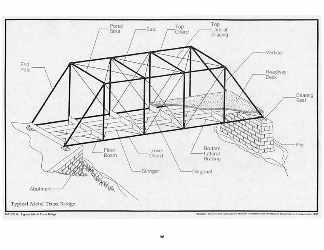
6662
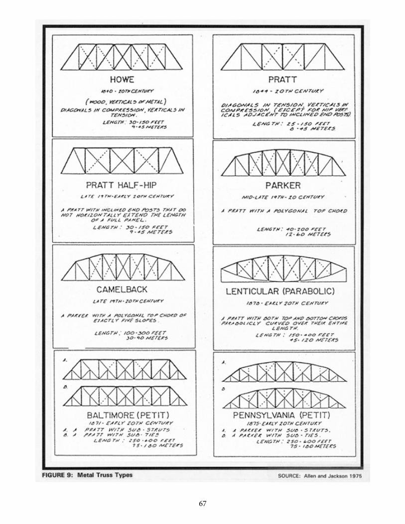
67 63
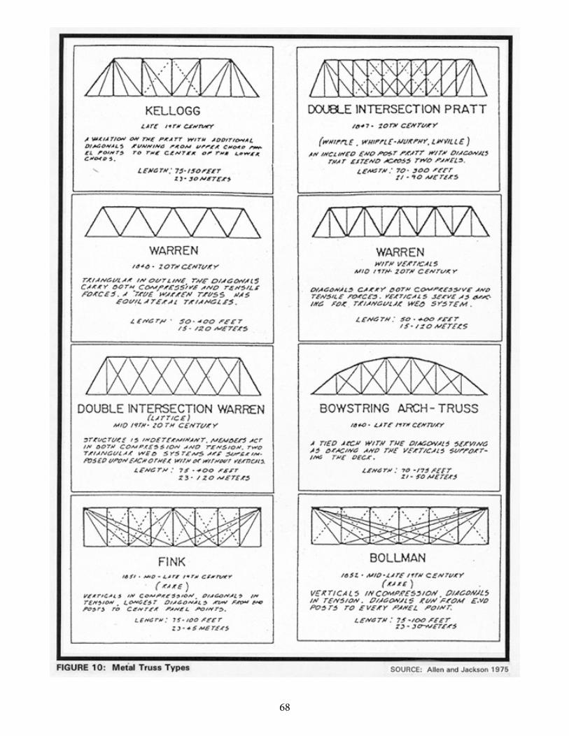
68 64
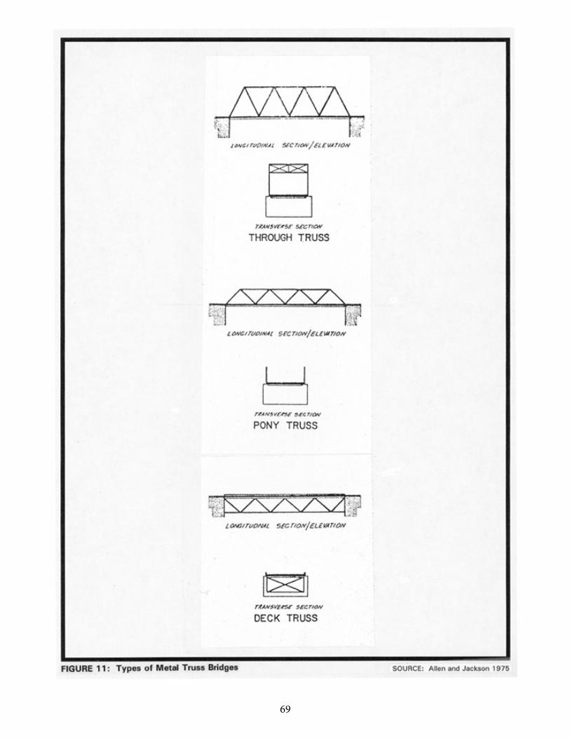
69 65
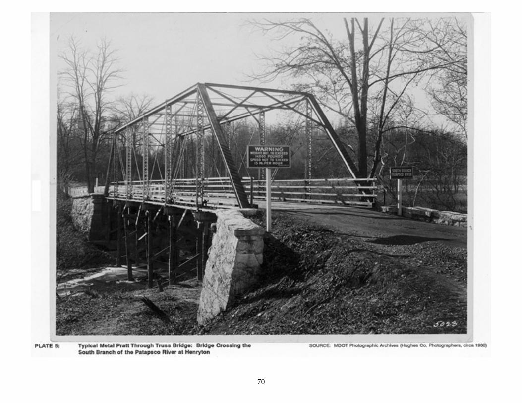
7066
71
67
Truss bridges of all forms typically include vertical members and diagonal members located between two horizontal components called chords (upper and lower, or top and bottom). Both wooden and metal truss bridges are categorized by their specific design, which varies considerably according to the shape of members and whether they are placed in compression or tension. Trusses may also be grouped according to the relation of the deck, or roadway floor, to the rest of the superstructure. If a truss bridge carries its deck level with its bottom chord, it is a through truss, and usually has overhead bracing including portal braces between its two sides. A pony truss is a type of through truss where there are no lateral braces connecting the top chords of the superstructure. By contrast, a deck truss carries traffic on a level with the top chord, with the truss positioned below the deck (Figure 12; Plates 6 and 7).
In the United States, timber bridges built between 1800 and 1900 incorporated various wooden truss designs including the simple king-post, the queen-post (lengthened version of the king-post), the Burr arch truss (where a wooden arch combined with a multiple king-post or other wooden truss forms to produce great strength), and the Town lattice (a dense system of intersecting wooden diagonals with no vertical members). In 1840, seeking to market his design to the emerging American railroads, including Maryland's Baltimore and Ohio, William Howe patented a truss bridge that was a key transitional form between the exclusive use of wood and the iron and steel trusses of the late nineteenth and early twentieth centuries. Howe's technological advance was to employ iron rods as verticals in tension, but the Howe truss retained the older usage of wooden diagonals in compression. The 1830-1840 period also witnessed construction of composite, timber and iron trusses on the B&O under Benjamin Latrobe and Army engineer Stephen H. Long, whose Long truss was patented in 1830 (Vogel 1964; DeLony 1993:42-43).
In his 1847 Work on Bridge Building, Squire Whipple moved truss technology a step further toward all-metal construction by his understanding of the structural properties of cast and wrought iron (Pennsylvania Historical and Museum Commission, and Pennsylvania Department of Transportation 1986:111). Cast iron was typically formed in a blast furnace where it was difficult to reduce a high carbon graphite level that induced brittleness. Wrought iron, however, was iron run through an additional "finery," or hearth, and with its reduced carbon content could be forged and would bend cold without cracking (Chard 1986:4-7). Whipple, who had built some of the earliest all-iron small bridges over the Erie Canal in the 1840s, suggested that cast iron, which fractures on impact and cannot carry tensile loads, be utilized for compression members in trusses, while the ductile wrought iron be reserved for tension members (Pennsylvania Historical and Museum Commission, and Pennsylvania Department of Transportation 1986:111). Herman Haupt's 1851 treatise A General Theory of Bridge Construction also promoted metal truss bridges as practical, durable alternatives when properly engineered (Tyrrell 1911:166).
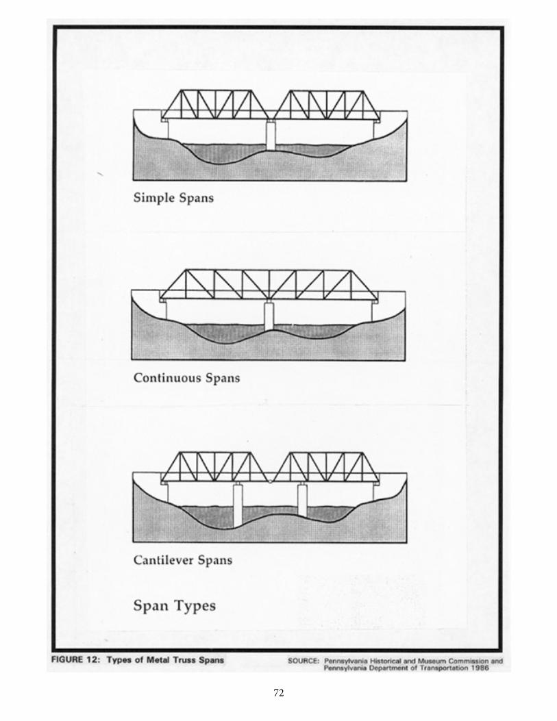
72 68
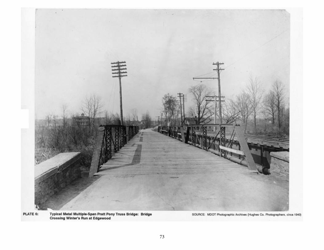
73 69
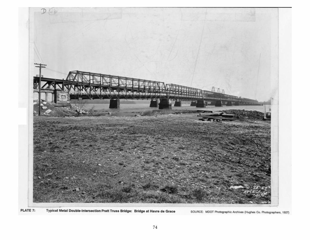
7470

75
71
Under the initial impetus of the expansion of American railroads, the period between 1840 and the Civil War saw the patenting and introduction of the majority of the earliest metal truss forms seen in the United States, including the popular Pratt (1844) and Warren (1848) types as well as Squire Whipple's bowstring truss (1841), his modified, "double intersection" Pratt (1847), Albert Fink's distinctive truss with long diagonals (1851), and the combination Burr arch and Pratt truss patented by Herman Haupt (1851) (Pennsylvania Historical and Museum Commission, and Pennsylvania Department of Transportation 1986:109-126). An event of signal importance in Maryland's bridge building history was Wendel Bollman's patenting of the Bollman truss in 1852; Bollman's truss, as described below, was utilized extensively on railroads and roads in the state, although the Bollman truss bridge at Savage Mill in Howard County is the only known surviving example in the world (Vogel 1964).
Bollman also evidently suggested the design for what became the popular Phoenix column, a cylindrical vertical member manufactured and marketed extensively by the Phoenix Bridge Company of Phoenixville, Pennsylvania. Based in Baltimore, Bollman's Patapsco Bridge Company and its rival, the Baltimore Bridge Company, run by distinguished engineers Benjamin and Charles Latrobe and Charles Shaler Smith, were significant early bridge building firms selling to railroads and local governments in Maryland and elsewhere (Vogel 1964).
The latter four decades of the nineteenth century brought improvements in metal truss technology to a peak, as an increasing number of "bridge works" and "iron works" in the eastern United States were able to fabricate built-up truss bridge members in the shop then ship them by rail to prospective bridge sites by prior arrangement with local officials, who in many cases had filled out order forms describing the type, size, and location of the desired spans (Pennsylvania Historical and Museum Commission, and Pennsylvania Department of Transportation 1986). Historical research and previous historic resource surveys of Maryland bridges have identified some twenty-five to thirty bridge companies that built, or may have built, truss bridges in the state between 1850 and 1920. (See below, under "Metal Truss Bridges in Maryland," for further discussion of these companies and bridges they are known to have built in Maryland.)
Refinement of mathematical analysis of truss design, as well as empirical observation of the bridges in the field, led to a large variety of modifications to the basic early metal truss types during the late nineteenth and early twentieth centuries. Significant modified varieties included the Baltimore truss, a Pratt with added strength derived from sub-struts or sub-ties that was used extensively on the B&O Railroad. Cantilevered truss construction methods, in which sections of a truss bridge were built out from piers with sometimes complex anchorage systems holding back the upper parts of the unfinished span, were also pioneered in the late nineteenth century, by a significant Baltimore-based engineer. Charles Shaler Smith, founding partner of Smith, Latrobe & Company and its successor the Baltimore Bridge Company during the 1870s, designed and built the world's first
76
72
high cantilevered truss, carrying the Southern railway over the Kentucky River in 1876-1877 (Schodek 1987:362). In 1939-1940, cantilevered truss construction methods were employed by the J.E. Greiner Company to build the Governor Harry W. Nice Memorial Bridge carrying U.S. 301 over the Potomac River (J.E. Greiner Company 1938:98-101).
The following short descriptions summarize the most important metal truss types developed during the nineteenth and early twentieth centuries in the United States, including transitional, modified, and some "hybrid" forms. Brief references are given to known structures in Maryland exemplifying each type (general sources for truss type information are Pennsylvania Historical and Museum Commission, and Pennsylvania Department of Transportation 1986 and P.A.C. Spero & Company 1991). No early transitional truss structures constructed of wood and iron appear to have survived in Maryland judging from research and previous survey information. Further discussion of significant Maryland metal truss bridges, their approximate numbers and distribution, and highlights of their history may be found below in the subsection entitled "Metal Truss Bridges in Maryland."
77
72
The Pratt Truss
The Pratt truss was first developed in 1844 under patent of Thomas andCaleb Pratt. Prevalent from the 1840s through the early twentieth century, thePratt has diagonals in tension, verticals in compression, except for the hip verticals immediately adjacent to the inclined end posts of the bridge. Pratt trusses wereinitially built as a combination wood and iron truss, but were soon constructed iniron only. The Pratt type successfully survived the transition to iron constructionas well as the second transition to steel usage. The Pratt truss inspired a largenumber of variations and modified subtypes during the nineteenth and earlytwentieth centuries.
The majority of Maryland's surviving metal truss bridges are Pratt throughand pony trusses, including both pin-connected and riveted examples. Knownearly examples described in existing Maryland Historical Trust historic resourcesurvey forms include the Four Points Bridge over Tom's Creek in Frederick County(MHT F-6-9; pin-connected through truss built 1876 by Wrought Iron BridgeCompany of Canton, Ohio) and the Gapland Road Bridge in the same county(MHT F-2-3; pin-connected pony truss built 1879).
Major subtypes of the Pratt design included:
Double Intersection Pratt Truss (Whipple, Whipple-Murphy, or Linville) This subtype was patented in 1847 by Squire Whipple and modified in
1863 through addition of crossed diagonals by Lehigh Valley RailroadChief Engineer John W. Murphy. Prevalent through late nineteenth and early twentieth century. The Double Intersection Pratt bridge ischaracterized by additional diagonals extending across two panels of the basic Pratt truss. This subtype was widely used for long-span railroadbridges. The only known previously surveyed Maryland example of aDouble Intersection Pratt is the Poffenberger Road Bridge (MHT F-2-5and HAER No. MD-35) in Frederick County, a pin-connected version.
Pratt Half-Hip Truss
The Pratt Half-Hip subtype was developed during the latter part of thenineteenth century. Characterized by inclined end posts that do notextend the length of a full panel, this subtype became popular in theUnited States from the 1890s into the early twentieth century. Research has uncovered one previously identified Maryland example, a half-hipped, pin-connected pony truss built at an undetermined, early
78
73
twentieth century date by the Smith Bridge Company to carry Newcomer Road over Beaver Creek in Washington County (MHT-WA-II-475).
Parker Truss
The Parker truss was developed by C.H. Parker in a series of patents he filed between 1868 and 1871. Characterized by Pratt design but with an inclined top chord, the Parker truss was popular for longer spans wellinto the twentieth century. Maryland examples located through research include the Bullfrog Road Bridge over the Monocacy in Frederick County (MHT-F-6-8, a riveted through bridge built 1908 by York BridgeCompany) and several spans constructed by the State RoadsCommission during the 1930s.
Baltimore (Petit) Truss
Developed in 1871 by engineers of the Baltimore and Ohio andPennsylvania Railroad, the Baltimore (Petit) truss subtype was popularinto the early twentieth century. The Baltimore (Petit) truss wascharacterized by Pratt design featuring additional, auxiliary sub-struts or sub-ties linking the chords and the diagonal and vertical members.Maryland examples located through research include Bridge 1679, asteel bridge taking the Western Maryland Railroad over the NationalRoad at Cumberland (MHT-AL-V-B-151, built 1912) and the Old PostRoad Bridge near Havre de Grace (MHT-H-12073, built of steel in 1905by American Bridge Company).
Pennsylvania (Petit) Truss
The Pennsylvania (Petit) truss was introduced during the mid-1870s as a variant of the Parker truss. Like the Baltimore (Petit) design, thePennsylvania (Petit) was characterized by the addition of sub-struts (toresist stresses) or sub-ties (to transmit stresses) to a demonstrablyuseful form (the Parker). Pennsylvania (Petit) trusses were erected well into the twentieth century. A known, significant Maryland example is the 1924 Glendale Road Bridge in Garrett County, comprising two spansbuilt by McClintic-Marshall during the construction of Deep Creek Lake(HAER No. MD-88).
Camelback Truss
Also a variation on the Parker truss design, the Camelback truss was

79
74
characterized by its distinctive polygonal top chord consisting of exactlyfive slopes. The Camelback truss was popular for through spansprimarily from its inception in the late nineteenth century through themid-twentieth century. Maryland examples discovered through research may include a group of bridges built in the 1920s and early 1930s under the aegis of the State Roads Commission.
80
74
The Warren Truss
Patented in 1846 by British engineers James Warren and Willoughby Monzoni, the Warren truss and its variants constitute a commonly built metal truss bridge type of the nineteenth and early twentieth centuries. The original form of the Warren was purely a series of equilateral triangles in which the diagonals carried both compressive and tensile loads. Later, verticals were added but served only as bracing for the entire triangular web system between parallel top and bottom chords. Like the Pratt truss, the Warren truss was widely built throughout the United States from the middle of the nineteenth century well into the twentieth century, and spawned many variants, including a double intersection, or lattice, subtype in which two triangular truss systems are superimposed with or without verticals.
Research located Maryland Historical Trust historic resource survey forms for two Warren steel trusses in Maryland: the 1907 Carter Farm Bridge on Deer Creek in Harford County (MHT-HA-799; this bridge was evidently moved from another site, as were many other highly adaptable short span trusses in the United States) and the 1910 Reel's Mill Road Bridge over Bush Creek in Frederick County (MHT-F-5-8). Both bridges were riveted pony trusses built by the prolific York Bridge Company of York, Pennsylvania.
81
75
The Bowstring Arch-Truss
A highly significant type including an arched upper chord (tied, or rigidly fixed at the abutments) with diagonals serving as bracing and supporting the roadway, the bowstring arch-truss's development dates from Squire Whipple's patent of 1841. Although Whipple and bridge engineers such as Thomas Moseley patented proprietary forms of the bowstring arch, the arch-truss in the bowstring configuration (with Pratt or Warren trusses) was not frequently built until the late nineteenth century, primarily for lightly traveled rural roads requiring relatively small spans. The development of metal bowstring arch structures is discussed in greater detail in the section of this report entitled "Metal Suspension, Arch, and Cantilever Bridges." Research uncovered previous Maryland Historical Trust survey forms or HAER recordations for one bowstring arch-through truss bridge (HAER No. MD-83; the Waverly Street Bridge at Williamsport) and three pin-connected pony trusses on rural roads (MHT-F-2-5, the Crum Road Bridge over Israel Creek in Frederick County, built circa 1875 by the King Iron Bridge Company; MHT-F-2-2, the Bennies Hill Road Bridge over Catoctin Creek, also a King product built circa 1880 in Frederick County; and MHT-HA-1237, Bridge 51 in the Whitakers Mill Historic District, Harford County, a bowstring arch-truss bridge of undetermined date featuring a Warren truss configuration).
82
75
The Bollman Truss
Once widespread but now reduced to a single known extant example in the world, located over the Little Patuxent River at Savage Mill in Howard County, Maryland, the Bollman truss type is perhaps Maryland's most significant contribution to metal truss design, if not American civil engineering itself. Wendel Bollman's national significance as an early, innovative bridge engineer has been chronicled by technological historian Robert Vogel (Vogel 1964) and is discussed in more detail below in the subsection "Metal Truss Bridges in Maryland." Patented in 1852 and utilized extensively on the Baltimore and Ohio Railroad, for which Bollman worked as master of road, the Bollman truss featured vertical members in tension, with diagonals also in tension and running from the top corner of each truss endpost to every panel point (joint where verticals met the lower chord) on the truss. Vogel has shown that Bollman's truss was, as Bollman originally maintained, a composite suspension-and-truss bridge, with a non-structurally functional lower chord and diagonals performing much like the suspenders or hangers on a suspension bridge (Vogel 1964).
Like the similar truss developed by Albert Fink for the B&O and other railroads, Bollman's truss represents the key transitional stage in American bridge engineering between empirical, rule-of-thumb design and the mathematical analysis of truss loading promoted by such engineers as Squire Whipple and Herman Haupt. Although his Patapsco Bridge Company offered Pratt trusses as well as his own patented truss for railroads and highways, the Baltimore-born Bollman stands as one of the most important engineering figures of the industrializing nineteenth century. Bollman bridges were built so often by the B&O between 1850 and 1880 that the railroad has accurately been spoken of as being "Bollmanized," but such structures were also located on roads in Baltimore City and County as well as western Maryland (Harwood 1979; Vogel 1964).
83
76
The Wichert Truss
During the late nineteenth and early twentieth centuries, many variants of the Pratt and Warren truss designs were developed and put into service on United States roads and railroads. An additional significant twentieth century truss type which deserves mention is the Wichert truss, which was utilized in several important bridges built in Maryland.
The Wichert truss is a significant type of continuous truss. Continuous trusses have a chord and web configuration that continues uninterrupted over one or more intermediate supports, compared with simply supported trusses which are supported only at each end. Due to concerns over potential stresses caused by intermediate pier settlement, continuous trusses were not generally employed until the early twentieth century. In 1930, E.M. Wichert of Pittsburgh addressed the problem with his Wichert truss, a continuous truss in which hinged quadrilateral sections were included over the intermediate piers. Wichert's first major truss bridge constructed to this design was the 1937 Homestead High Level Bridge over the Monongahela River at Pittsburgh.
Maryland State Roads Commission engineers, noting the usefulness of the Wichert design for long river spans, built an early example of the Wichert truss between 1937 and 1939, in cooperation with the West Virginia State Roads Commission. A high-level crossing of the Potomac connecting Shepherdstown, West Virginia, with Washington County, Maryland, this extant 1,020-foot-long structure includes six spans of Wichert continuous deck trusses with a 24-foot clear roadway (Maryland State Roads Commission 1939a:80; Pennsylvania Historical and Museum Commission, and Pennsylvania Department of Transportation 1986:124). In 1939-1940, J.E. Greiner Company and the Maryland State Roads Commission incorporated Wichert-type deck trusses in the Governor Harry Nice Memorial Bridge over the Potomac and the Thomas Hatem Memorial Bridge crossing the Susquehanna at Havre de Grace (J.E. Greiner Company 1938). Continuous deck trusses were also utilized in portions of the first Chesapeake Bay Bridge, built between 1949 and 1952 by Greiner under state contract (Brown 1952:17).
84
77
Post-1900 Patterns in Truss Fabrication and Use
The Good Roads movement of the 1880-1900 period prompted calls forimprovement of ordinary bridge structures as well, and in numerous jurisdictionsofficial policy called for replacement of older wooden bridges with metal trusses.The development of the Bessemer and open hearth processes permitted themanufacture of low-carbon structural steel, which became generally available for truss bridge construction during the 1890s (Chard 1986). Other late nineteenthand early twentieth century technological improvements, such as the invention of the portable pneumatic riveter, allowed great flexibility in truss construction. By1920, built-up truss members could be shop-riveted and the bridge connectionsriveted on site.
Engineering handbooks of the 1890-1920 period accurately reflected theremarkable versatility and usefulness of the metal truss bridge, whether pin-connected or riveted, built in iron or steel, or utilized for fixed or movable spans.Milo Ketchum's 1908 text The Design of Highway Bridges noted American Bridge Company standards recommending pin-connected or riveted Pratt throughtrusses for highway bridges of 80 to 168 feet, quadrangular Warren rivetedtrusses for 80- to 152-foot spans, Camelback trusses (Pratts with polygonal topchords, usually having five slopes) for 168- to 220-foot crossings, and pin-connected Petit trusses for spans longer than 220 feet (Ketchum 1908:213).
In 1924, the American Society of Civil Engineers' Special Committee onSpecifications for Bridge Design and Construction issued a final report on"specifications for design and construction of steel highway bridgesuperstructure." The committee, which included prominent Baltimore engineerJ.E. Greiner, recommended rolled beam bridges up to 40 feet long, plate girders or lattice trusses from 30 to 100 feet, riveted half-through (or pony) trussesbetween 50 and 100 feet, riveted trusses at 90 feet and over, and riveted or pin-connected trusses at 150 feet and over (American Society of Civil EngineersSpecial Committee on Specifications for Bridge Design and Construction1924:267).
In 1933, Victor Brown and Carleton Conner in their Low Cost Roads andBridges noted several changing patterns in modern roadway truss usage. While"truss spans for low cost bridges" were "commonly of structural steel" and ranged from 60 feet to 250 feet, Brown and Conner found that "near the lower limits and up to 100 feet, the rolled steel I-beam is replacing the pony and short span steel truss." With the development of heavy trucks, which featured high cabs andtrailers, deck trusses of steel were gradually replacing through trusses whoseportals and overhead bracing limited vertical clearance. Brown and Connerrecommended a variety of efficient inexpensive crossings, includingcombinations of through trusses or pony trusses with reinforced concrete andsteel girder approach spans (Brown and Conner 1933:510-516).
8578
METAL TRUSS BRIDGES IN MARYLAND
The development of the metal truss bridge in Maryland resulted from theearly growth of railroads in the state. Although Squire Whipple in the early 1840s had designed a number of small iron truss bridges over the Erie Canal in NewYork State, Maryland soon thereafter became a laboratory for experimentation inadapting iron to railroad bridge design. It was necessity that caused the railroadsto pioneer the construction of metal truss bridges: the railroads' heavy locomotives and rolling stock required bridges far stronger and more reliable than those yetbuilt for highway use.
The earliest attempts to adapt truss designs to metal construction werecharacterized by "an intuitive sense of proportion, stress, and the general 'fitnessof things'" that lacked exact science (Vogel 1964:80). Such vagueness hadsufficed when constructing timber bridges for the relatively light loads to whichhighway bridges of the time were subjected, but the results were frequentlyuncertain when this approach was applied to new materials and new uses.Perhaps the first metal truss bridge in the state was an iron Howe truss that waserected in 1846 at Monument Street in Baltimore to accommodate the Baltimoreand Susquehanna Railroad. It appears that the City of Baltimore appropriated$6,000 to J.R. Trimble to erect the bridge; it is not known how successful theenterprise was. Another bridge built at about the same time was a metal trussusing cast iron compression members and wrought iron in tension. Unfortunately, it is not known what truss design was used, but the design, materials, orworkmanship proved defective; the bridge suffered "absolute collapse" in 1848"without any warning and in the absence of any unusual loading" (Hilton 1913).
It was under the aegis of the Baltimore and Ohio Railroad in the 1850s that the idea of the metal truss was brought to successful fruition. In his 1849 ChiefEngineer's report, Benjamin H. Latrobe announced that "reconstruction of thelarge Bridges at Little Patuxent and at Bladensburg. . .will be executed in a fewmonths. . . . It is proposed to erect a superstructure of Iron upon stone abutments, at each place -with increased span, for greater security against future floods"(Vogel 1964:88).
The design that was subsequently to be known as the Bollman truss waswhat Latrobe had in mind. The design, which owed some debt to Latrobe's ownwork with radiating struts, was the creation of B&O's master of road, WendelBollman. One year later, in 1850, the first manifestation of Bollman's design waserected over the Little Patuxent River at Savage Factory. The 76-foot-longSavage Bridge and its sister bridge at Bladensburg gave "much satisfaction" andcaused Latrobe in his 1850 report to express great confidence in the future of iron bridge construction. Soon thereafter, Bollman truss replacements were erected by the B&O over the Patapsco River at Elysville and over the Potomac River atHarpers Ferry, followed by numerous B&O Bollman trusses in Maryland and other
8679
states.
Bollman was a transitional figure between intuitive and exact engineering.Although he made use of mathematical analysis, he also relied upon empiricalmethods to test his designs. He would frequently build models of his designs and then load them until they collapsed in order to discover weaknesses (Vogel1964:83). Bollman applied for a patent on his truss design in 1851 and received it in 1852. No later than 1855, one of Bollman's former B&O assistants, John H.Tegmeyer (subsequently Baltimore City Commissioner), formed a company inBaltimore that advertised "Wendel Bollman's Patent Iron Suspension RailroadBridge" in several railway journals (Vogel 1964:87, 91).
Although the design was marketed to railroads, it appears that AlleganyCounty Commissioners and the Cumberland City Council took notice of theBollman truss in 1854. Will's Creek in Cumberland had been the site of at least six ill-fated bridges since 1755, including an iron suspension bridge that lasted from1816 to 1838. The suspension bridge's timber replacement was in completedisrepair by 1854 when the County Commissioners and the City Council agreed to split the cost of replacing it. According to an 1878 account, "a contract was madewith a Baltimore firm for the erection of an iron bridge of the Bollman pattern," and the bridge was completed by the end of the year (Lowdermilk 1971:371). Although it is unclear if this Cumberland bridge was the first metal truss highway bridge inMaryland, it was certainly one of the first, and appears to be the first directtranslation of railroad-developed metal truss technology to highway use in thestate. The Will's Creek Bridge had lasted 38 years when it was replaced in 1892, far longer than any of its predecessors at the site.
As a nexus for railways and the accompanying concentration of engineering talent, Baltimore rapidly became an early center of bridge building activity. Notonly were there railroad bridges to construct in the city and its environs, butBaltimore had need of a great number of metal highway bridges as the earliertimber bridges proved unequal to the traffic demands placed on them by thegrowing city.
In 1858, Bollman left the employ of the B&O and joined John Tegmeyer and John Clark in Baltimore to found W. Bollman and Company, apparently the firstcompany in the nation to design, fabricate, and erect bridges (Vogel 1964:91).Advertising designs for roofs, engine houses, and machine shops as well asBollman truss bridges, the company ceased operations in the early 1860s because of the Civil War. Before its close, W. Bollman and Company obtainedconsiderable B&O work (Olson 1980:107). After the conclusion of the Civil War, in 1865, Bollman (John Tegmeyer having become City Commissioner of Baltimore)organized the Patapsco Bridge and Iron Works, which built railroad and highwaybridges (including other proprietary types as well as Bollman trusses) not only inMaryland, but also in North Carolina, Cuba, and Mexico until the company wasdissolved upon Bollman's death in 1884. One of Bollman's last projects was the
8780
replacement of the movable bridge at the mouth of the Jones Falls (giving entry to the City Dock) with a truss swing span that opened for travel in 1880 (BaltimoreCity, Jones' Falls Commission 1882:695). This project was conducted under theaegis of the Commission for the Improvement of Jones' Falls, formed in response to the flooding of 1868 and the drought of 1872 (Olson 1980:163).
Bollman's chief Baltimore competitor was Smith, Latrobe and Company,organized by Charles Shaler Smith, Benjamin H. Latrobe, and C.H. Latrobe in1866, and reorganized as the Baltimore Bridge Company in 1869. Before itsdissolution in 1880, this company constructed major bridges across theMississippi, Missouri, and Kentucky rivers (built in 1876, the Kentucky River Bridge was the first major cantilever bridge in the nation).
H.A. Ramsay & Co. was another bridge firm operating in Baltimore in the1870s and 1880s. This firm was responsible for at least three of the bridges built by the Jones' Falls Commission in the 1880s. The first, a replacement at PrattStreet, was a heavy wrought-iron bridge of 106 feet, including three 20-foot-longthrough trusses. The second was at Chase Street, crossing both Jones Falls and the tracks of the Northern Central Railroad; it consisted of two spans "of thetriangular type." The third bridge built over the Jones Falls was a heavy three-span though truss. All three of these bridges were built by Ramsay in 1881(Baltimore City, Jones' Falls Commission 1882:697-699).
Other bridge-building firms operating in Baltimore in the nineteenth centurywere Campbell and Zell Company (1896-1899); J.G. Clarke and Company,subsequently Clarke Bridge Company (1879-1883); A. and W. Denmead andSons (1850s); and Murray and Hazelhurst (building bridges 1857-1869).
Baltimore's flurry of metal truss bridge activity from the 1850s through the1880s, along with the 1854 Bollman truss bridge over Will's Creek in Alleganycounty, proved the usefulness of metal truss bridge design to highwayapplications. County Commissioners in the Piedmont and Appalachian Plateaucounties soon took notice of Baltimore's experience. They undoubtedly noticed,too, that the metal trusses the railroads were erecting in their counties werewithstanding prodigious loadings and were not being washed away by everyspring freshet. The typical timber beam bridge so prevalent in the counties wasnotorious for its inability to deal with either challenge. In addition, the timberbridge, covered or uncovered, was subject to decay and required a considerableamount of maintenance. The proven ability of metal truss bridges to bear greatloads and to remain standing through flood and time must have impressed county commissioners considerably.
However, erecting metal truss bridges was a proposition qualitativelydifferent from the way counties had hitherto built bridges. With timber or stonearch bridges, a local artisan was contracted to build the structure and beresponsible for its upkeep (Thomas and Williams 1969:271). With metal truss
8881
bridges, not only was the engineering talent needed to design them usuallyunavailable locally, but the metal members of the truss could be produced only atmajor foundries. The advent of the metal truss required the importation ofexpertise and materials from urban areas.
The formation of Bollman's companies in their various manifestations(starting with John Tegmeyer's enterprise) provided the means by which countiescould import both the necessary design expertise and the actual spans into theirlocales at a reasonable cost. In the early years of Bollman's companies andsubsequent rival companies, it was probably necessary for a firm is representative to visit the site of the proposed bridge and return to the company's fabricationplant with the necessary data. Soon, however, the process was streamlined; thefabricating companies provided local officials with all the information necessary todetermine which truss type was suitable for a given site. The local officials wouldthen complete and return to the fabricating company an order form that providedall the data necessary to the fabrication of the desired bridge. The bridgecompany would then fabricate the truss members and ship them to the site, along with detailed instructions (and imprints or matchmarks on the members) for theerection of the bridge. Finally, the local officials would have the truss erected onabutments made by local masons.
Numerous companies across the nation were formed to provide metal truss bridges to cities, towns, and counties. The Baltimore companies described above conducted a degree of business in Maryland, but the Patapsco Bridge andBaltimore Bridge companies by the 1870s had begun to expand to other statesand countries. The bridge building business became extremely competitive, withcompanies from other states also expanding into Maryland. Information gatheredfrom previous Maryland Historical Trust historic resource survey forms on metaltruss bridges in Maryland indicates that a number of bridge companies providedmetal truss bridges in the late nineteenth and early twentieth centuries, includingthe following firms:
Wrought Iron Bridge Company, Canton, Ohio - built Pratt throughtruss bridges in Maryland from 1870s through 1890s;
King Iron Bridge Company, Cleveland, Ohio - built Pratt andbowstring trusses in Maryland from 1880 through 1892;
Patapsco Bridge and Iron Works, Baltimore - in addition to its work in Baltimore, built a Pratt pony truss in 1879;
Baltimore Bridge Company - in addition to its work in Baltimore, built a Pratt pony truss in 1885;
Pittsburg Bridge Company, Pittsburgh, Pennsylvania - built a Prattthrough truss in 1882;
89
82
Smith Bridge Company, Toledo, Ohio - built Pratt and Pratt half-hipped trusses from 1889 through 1890;
Groton Bridge and Manufacturing Company, Groton, New York -built Pratt pony trusses in the last years of the nineteenth century;
York Bridge Company, York, Pennsylvania - built Pratt, Warren, and Parker trusses in the first quarter of the twentieth century;
Vincennes Bridge Company, Vincennes, Indiana - built a Prattthrough truss in the first quarter of the twentieth century;
John Stauver McIlvane, Philadelphia, Pennsylvania - built a modified Pratt pony truss in 1909.
Not surprisingly, given its close proximity to Baltimore City, BaltimoreCounty appears to have taken the lead among Maryland counties in erecting metal truss bridges at an early date, not always with the happiest of results. By 1868 the county apparently had erected an iron truss bridge in Phoenix, a bridge that metthe same fate as so many in 1868, being washed away by the floods of November (McGrain n.d.). The loss of this bridge may have caused some second thoughtsabout the invincibility of metal trusses, for in 1874 the county solicited sealedproposals "for building an open wooden truss bridge, on the Burr Truss plan, over the Gunpowder Falls" (McGrain n.d.).
Despite this regression, there is a great deal of evidence that metal trussbridges were totally back in favor by the 1880s. As an example, in 1884 H.A.Nagle, Superintendent of Bridges for Baltimore County, advertised for sealedproposals for "a wrought iron Pratt truss bridge over the Big Gunpowder Falls."Nagle was very specific about what type of bridge the county wanted, stipulatingthat "parties tendering must furnish a clearly made out strain sheet of their design" for a "through bridge, consisting of one span 86 feet between masonry" with aroadway "12 feet wide in the clear and not less that 13 feet high in the clear"(McGrain n.d.).
Such advertisements attracted a healthy response; one such advertisement for yet another bridge over Gunpowder Falls received bids from nine bridgecompanies, including The Penn Bridge Company, H.A. Ramsay and Sons,Pittsburg Bridge Company, the Wrought Iron Bridge Company, and the KingBridge Company (McGrain n.d.). Clearly, the Superintendent of Bridges was able to satisfy his requirements for metal truss bridges in Baltimore County.
Judging from available information, the distribution of metal trusses inMaryland encompasses few in the Tidewater, but a number of examples, with
9083
fairly equal distribution, in the Piedmont and Appalachian Plateau. One exception is Frederick County, where the York Bridge Company in the early twentiethcentury built a great number of metal trusses, primarily Pratt but also Warren and Parker trusses. In the same county, King Iron Bridge Manufacturing Companyerected several bowstring pony truss bridges. It is possible that there areinaccuracies in these estimates of preliminary distribution trends owing to thevariation in the level of available documentation throughout the counties.
By the turn of the century, reinforced concrete technology had made greatstrides and local officials thus had another option from which to choose. In somecounties, such as Baltimore County, reinforced concrete bridge technology waseagerly embraced at an early date. Just as Baltimore County had been in theforefront among counties in the adoption of the metal truss in the third quarter ofthe nineteenth century, it was also the first county to build a reinforced concretebridge in the first quarter of the twentieth. In fact, the 25-foot reinforced concretebeam bridge near Sherwood Station was the first of its kind in the state, and in the words of its creators "shows the progressive character of the work that the County Roads Engineer is inaugurating" (Johnson 1903:169).
As evidenced by Baltimore County Reports in subsequent years, this bridge was the harbinger of the future; reinforced concrete structures were rapidly to gain ascendancy over the metal truss in the county. The announcement of theSherwood Bridge provides the rationale: "Steel rods are imbedded in the concrete beams to enable them to withstand heavy loads; but no steel surface is exposed to the air, so that there is practically no cost for maintenance of a bridge of thischaracter" (Johnson 1903:169).
Although other counties were not quite so quick to embrace the newtechnology, reinforced concrete bridges began to compete with truss bridges forthe small to moderate spans across rivers and creeks. The State RoadsCommission committed itself at the end of the first decade to developing standard plans for reinforced concrete bridges and intensified its efforts in the 1920s.
Metal truss bridges were still being erected throughout the state, but insignificantly declining numbers. The older metal bridge fabricators weredisappearing, or had already disappeared, by this time. A new, and lessnumerous, generation of metal truss fabricators (many comprising largecompanies which absorbed smaller competitors) met the needs of this decliningmarket:
Bethlehem Steel, Bethlehem, Pennsylvania - built at least onecamelback through truss in the 1920s;
American Bridge Company, Ambridge, Pennsylvania - built Pratt and camelback trusses in 1920s and 1930s;
9184
McClintic-Marshall, Pittsburgh, Pennsylvania - built Pratt, Parker, and Camelback trusses beginning in the teens through the early 1930s;
Roanoke Iron and Bridge Company, Roanoke, Virginia - built Prattand Camelback trusses in the 1920s and 1930s.
Besides the decline in numbers, the character of truss bridges waschanging; the lighter and more delicate appearance of nineteenth century trusseswas giving way to more solid forms that addressed the heavier load requirementsnecessitated by the dramatically increasing loads, volumes, and speeds ofautomobile and truck traffic on Maryland roads.
Although reinforced concrete designs dominated the spanning of small tomoderate crossings by the 1930s, the metal truss assumed renewed prominenceas the means by which monumental bridges spanning major rivers were built inthe late 1930s and 1940s. The bridges over the Susquehanna River at Havre deGrace and over the Potomac at Ludlows Ferry, and the Wichert truss bridge overthe Potomac at Washington County heralded a new era in truss bridge building.These bridges exemplified the adaptability of the form as it continued to evolve inresponse to the need to span longer distances and carry heavier loads.
9284
Conclusion
The following summary statements regarding structural characteristics formetal truss bridges, key periods of significance for metal truss bridges inMaryland, and the earliest known documented examples of metal truss bridges in the state are based solely on documentary research.
Metal truss bridges (see Figures 8 through 12 and Plates 5 through 7)comprise two parallel trusses and a floor system supported on a concrete ormasonry substructure. Each metal truss consists of individual componentsconnected in a series of triangles. The particular type of metal truss bridge isdefined by the arrangement of individual members, and the way in which thosemembers are stressed (compression or tension); a wide variety of configurations is possible, many of which were proprietary, or patented variants, such as thecommonly known Pratt and Warren types.
Individual members form the horizontal portions of the truss, called top and bottom chords, and the vertical and diagonal web members. The verticals anddiagonals are connected to the top and bottom chords at joints (pin connections or rivet connections are possible). Minor web components may include sub-struts or sub-ties. Members may be in tension or compression, depending on the variety of truss (see Figures 9 through 12).
Other basic components include the portal, stringers, floorbeams, and deck.Portal bracing provides lateral bracing for the two parallel trusses at the top of the end posts. Stringers are longitudinal members which transmit loads to thefloorbeams, which in turn transmit loads to the trusses at each panel point (jointconnection) where the floor beams, the chord, and the verticals and diagonals are connected.
In addition to proprietary types, metal truss bridges are categorized by therelationship of the roadway to the truss. Simply stated, if the truss system risesabove the roadway or deck level but does not include overhead portal bracing, the bridge is termed a pony, or half-through truss. If portal bracing connects thetrusses, the span is a through truss. If the truss system is located entirely beneath the deck, the bridge is called a deck truss.
Key periods of significance for metal truss bridges in Maryland, as indicated by documentary research, include 1840-1860, the transitional period from timbertrusses through iron-and-timber structures to all-metal trusses during which earlymetal truss designs (Pratt, Howe and others) were patented and B&O bridgebuilders Benjamin Latrobe and Wendell Bollman introduced the Bollman truss(1851); 1860-1900, the era of metal truss bridge popularization for railroad andhighway use, and the movement toward all-steel trusses rather than iron bridges;and 1900-1960, the period in which metal truss spans for highway use were
9385
increasingly standardized under the impetus of organizations such as theAmerican Society of Civil Engineers, and also the era when the modern metalgirder bridge, which could be readily widened, gradually replaced the metal trussbridge for all but monumental spans and their approaches (the 1940 GovernorHarry Nice Bridge over the Potomac River, the 1940 Thomas Hatem Bridge overthe Susquehanna, the 1952 Chesapeake Bay Bridge, and several westernMaryland bridges featuring Wichert truss systems employed combinations of deck trusses and through metal trusses).
The earliest known documented examples of metal truss bridges inMaryland are the nationally significant Bollman Truss Bridge in Savage (1869;moved 1887) and iron bowstring trusses and Pratt trusses in Frederick Countydating to the 1870s. Documentation exists that metal truss bridges wereemployed on the B&O Railroad, Northern Central Railroad, and in Baltimore Cityduring the 1850s and 1860s. As thorough surveys of existing truss bridges in allMaryland counties have not been performed, information about early constructiondates for this type of bridge is greatly skewed toward those counties where priorsurveys have taken place.
Based solely on prior survey information and research, it appears that theunique Bollman Truss at Savage is the earliest extant metal truss bridge inMaryland and the only surviving example of its type in the United States. Priorsurvey information similarly indicates that metal truss "firsts" in Maryland mayinclude the Poffenberger Road Bridge over Catoctin Creek, a Double-IntersectionPratt Truss built circa 1878 (MHT F-2-5); the Crum Road Bridge over Israel Creek, a bowstring pony truss built circa 1875 (MHT F-8-2); and the Four Points Bridgeover Tom's Creek (MHT F-6-7), a Pratt through truss built in 1876. Theseconclusions, however, as well as a securely dated chronology of extant early metal truss bridges in Maryland, must necessarily be verified through field survey.
Judging from documentary research, twentieth century developments inmetal truss fabrication and use, such as employment of riveted connections rather than pin-connection, are well represented in Maryland. The earliest Wicherttrusses known to have been built in Maryland were incorporated into a 1,020-foot-long bridge between Washington County, Maryland, and Shepherdstown, WestVirginia, in 1937-1939 by the Maryland State Roads Commission in cooperationwith West Virginia authorities.
94
87
SECTION VI: MOVABLE BRIDGES
HISTORICAL DEVELOPMENT
As mentioned in the discussion of Maryland transportation history earlier in this report, rivers and creeks were the primary means of transportation for early residents of Maryland. The gradual construction of roads in the colony encountered rivers as obstacles that had to be crossed, but when those rivers served as the primary avenues of transportation, it was not sufficient simply to build a bridge over the river. When those rivers were navigable, some means had to be found to cross the river and at the same time permit the river's navigation. In order to allow vessels to navigate a bridged waterway, one must build either a high, fixed bridge with adequate clearance or a movable bridge with a span that moves out of the way when a vessel approaches. As building a high bridge usually required extensive approach work and very high grades, movable bridges became the predominant technological solution to the problem of how to bridge navigable waters.
In a 1907 paper intended to open discussion and establish specifications for movable bridges, C.C. Schneider, past president of the American Society of Civil Engineers, classified movable spans by the following categories (Schneider 1908:258-259):
1. Swing bridges, which turn about a vertical axis;
2. Bascule bridges, which turn about a horizontal axis or roll back on a circular segment;
3. Lift bridges, which lift vertically;
4. Traversing or retractile bridges;
5. Transporter or ferry bridges;
6. Pontoon or floating swing bridges.
Brief descriptions of these categories were provided in 1926 by Otis Hovey, Assistant Chief Engineer of the American Bridge Company, in his text Movable Bridges:
A swing bridge consists of a superstructure arranged to turn about the vertical axis of a pivot anchored to the center pier. In ordinary cases the
95
88
pivot is at the center of a span of two equal arms, which balance each other when the bridge is open, thus providing two equal openings for navigation. It is sometimes necessary to place the pivot near one end. The shorter arm must then be counterweighted to balance the longer arm when the bridge is open.
Bascule bridges are, strictly speaking, those in which one end rises as the other falls, but the term is commonly applied to any type moving about a horizontal axis, either fixed or moving, as well as to those that roll back on a circular segment [rolling lift bascule spans]. They may consist of a single leaf spanning the channel [single leaf] or of two symmetrical leaves [double leaf] meeting at the center.
Lift bridges moving vertically consist of simple spans resting on piers when closed. In most cases the weight of the lifting span is counterweighted by means of ropes, or chains, attached to the ends of the span and the counterweights, which pass up and over sheaves on top of towers at the ends of the bridge.
Retractile, or traversing, bridges [move] horizontally. When closed they form simple spans across the channels. Some telescope inside of the adjoining spans; others recede above the approaches, the rear end being tilted upward and the free end downward. In some cases the approach span is first moved aside, transversely, to permit the draw span to recede in its place.
Transporter, or ferry, bridges are rarely used. A fixed span across the channel is supported on shore towers at a sufficient height to clear navigation. A platform, or a car, is suspended under the span and arranged to travel across the channel from shore to shore.
Pontoon bridges are. . .adapted for use when local conditions prevent the construction of more stable structures when a temporary crossing must be quickly made, as in military operations. They may consist of small boats, or pontoons, lashed together for temporary use, or more elaborate and stable pontoons in permanent structures [Hovey 1926:17-19].
With the exception of transporter or ferry bridges, there is at least one historical example of each of the above categories of movable bridges over the navigable waters of Maryland; for the swing, bascule, and retractile categories, there are numerous examples (Figure 13; Plates 8 and 9). As examples of the type, Maryland's bridges represent a movable bridge technology with historical precedents dating to ancient times. Movable bridges were described by ancient historians, developed in the
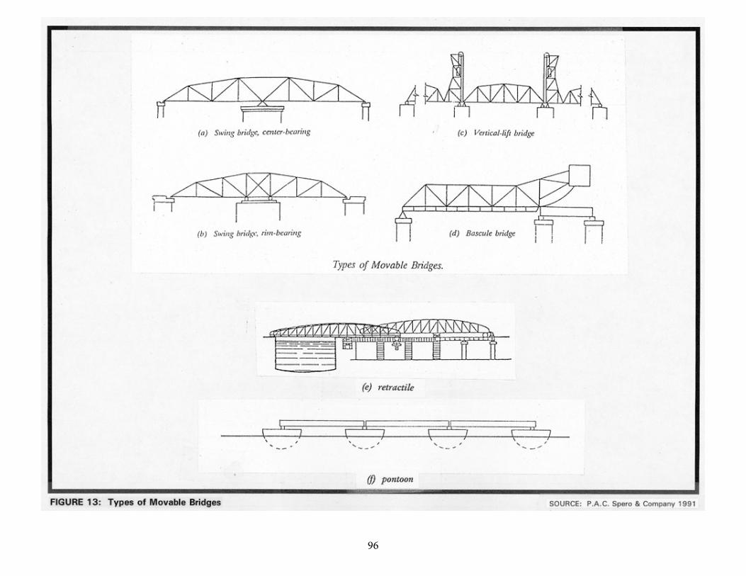
9689
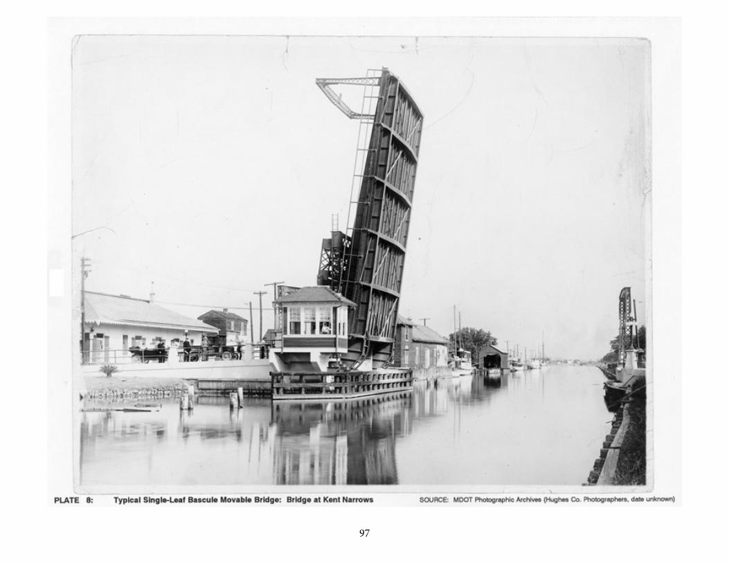
97 90
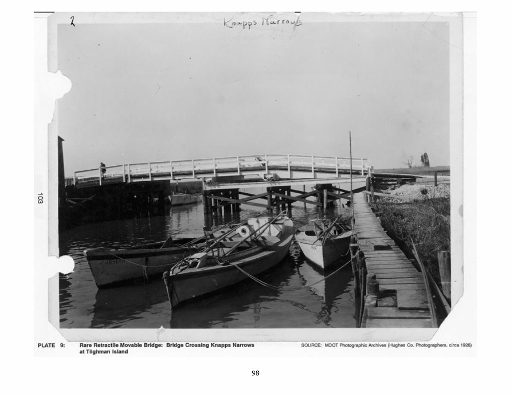
98 91
99
92
Renaissance, and flourished in the late nineteenth and early twentieth centuries. Today,as high bridges increasingly replace older movable bridges, the type has significantly declined as a bridge building option for navigable waters.
The operation of movable bridges in the United States is regulated by the U.S. Army Corps of Engineers, which was given authority over navigable waters by Congress in 1894 (U.S Army Corps of Engineers 1933:123). Listings of all bridges over navigable waters (U.S. Army Corps of Engineers 1926) and regulations governing the operation of each bridge (U.S. Army Corps of Engineers 1939) have been published periodically based on the navigation needs of the waterways. These regulations must be posted on upstream and downstream sides of the bridge. Some movable bridges had 24-hour service because the operator lived near the bridge and was able to respond to a boat whistle or horn blast; others required notice ranging from 4 to 24 hours. Some spans included operators' houses for the convenience of the tenders.
The following subsections summarize the development of each of the movable bridge categories which have been built in Maryland.
Swing Bridges
Although bascule bridges appear to have been much more common than swing spans in the middle ages, swing-span technology is documented during the Renaissance. In about 1500, Leonardo da Vinci made a sketch of an unequal-armed, or bob-tailed, center-bearing swing bridge which was swung by means of hand winches. By the early seventeenth century, the essentials of the center-bearing pivot as used in late nineteenth and early twentieth century swing spans had already been worked out. In 1625, the French "Royal Engineer-in-Chief," Salomen de Caux, designed a double-swing bridge for the large lock at Cherbourg. It consisted of two spans, each with two unequal arms, the longer arms (27 feet each) of both meeting at the center of the bridge. Each swing span revolved on a central iron bearing and was supported by balance wheels rolling on a circular track in order to steady the span as it spun to the open and closed positions (Hovey 1926:I, 12, 13).
The advent of metal structural members in the very late eighteenth century had a particularly beneficial impact on the development of movable spans. The first known metal bridge was the cast-iron arch bridge at Coalbrookdale, England, a non-movable bridge. But by 1805, iron was used in the construction of movable bridges at the London Docks. Soon thereafter, in 1818, a double swing span of iron was built at St. Katherine's Docks, near the Tower of London (Hovey 1926:I,13,14).
As in Europe, the first movable spans in America were constructed of wood. It is unclear when the first all-iron movable bridge was built in the United States, but
100
93
the Rush Street swing-span bridge erected in 1856 over the Chicago River appears to be one of the first examples of a large all-iron movable bridge in the nation (Hovey 1926:I,14,15). The Chicago River bridge was swung on a mechanism referred to as a rim-bearing pivot, in which the span's weight is supported by a series of wheels or bearings running on a circular track or drum on the top of the pier that bears the swing span. Developed in the early nineteenth century by English engineers, rim-bearing pivots were commonly thought to be necessary to bear the great weight of large swing spans. In the 1870s, American engineers began to build swing spans supported on center-bearing pivots (Hovey 1926:I, 36), returning to the simpler design pioneered in 1500 by Leonardo and utilized on all swing spans before the development of the rim-bearing pivot in the early nineteenth century.
Due to their simplicity, reliability, and comparative economy, the center-bearing design gradually prevailed over the more complex rim-bearing design. By the third decade of the twentieth century, the center-bearing type had nearly superseded the rim-bearing type for all but the widest city highway bridges. By that time, many engineers had come to appreciate the advantages of the swing span over rival forms of movable bridges. As Otis Hovey stated in 1926, "when there are no restricting circumstances, a swing bridge is the simplest, best, and most economical type in first cost and maintenance" (Hovey 1926:20). Disadvantages of swing bridges include slowness of operation, interference with the channel during operation, and obstruction of navigation when there is a series of swing spans in close proximity (Hool and Kinne 1943:1-3).
The jack-knife bridge is a special type of swing bridge used only for railway bridges, consisting of a deck girder under each rail, one or more needle beams under the free end, and a gallows frame over the pivots. The action of the bridge is quite similar to the old-fashioned parallel ruler. In 1926 Hovey dismissed the type as "nearly obsolete and will not receive further consideration" (Hovey 1926:18).
Bascule Bridges
Not all engineers agreed with Hovey's assessment of the superiority of the swing span; the bascule span had many adherents throughout its long history. In the twentieth century George Hool, Professor of Structural Engineering at the University of Wisconsin, strenuously advocated the benefits of the bascule in both his 1924 and 1943 editions of Movable and Long-Span Bridges. Hool's preference for the bascule was largely based on the rapidity with which a vessel could pass through the navigation channel of a bascule as compared a swing span channel, but he also adduced a number of other benefits including economy of operation (Hool and Kinne 1943:1-8). Although favoring swing-span bridges, Hovey acknowledged that the bascule was preferable when numerous parallel bridges had
101
94
to be erected over a river or when a city had a narrow waterway, as in Chicago (Hovey 1926:22).
Of the numerous examples of movable bridges built in the Middle Ages, the vast majority seem to have been bascules, in which the movable span swings upward as it opens to let vessels through. Drawbridges over moats are illustrative examples of this type of construction in its simplest form, as was probably the original London Bridge, completed in 1209. Bascule bridges may consist of one movable span ("single leaf") or two movable spans ("double leaf"); the double leaf is typically used when more navigational clearance is needed. Most of the early bascules were operated by an "out-haul line attached to the free end and running upward and inward to the source of power" (Hool and Kinne 1943:1). Although the majority of these bascules did not have counterweights, thereby increasing the effort to operate them, counterweighted bascules designed by military engineers began to appear on European artificial waterways in the eighteenth century (Hovey 1926:7). In 1839 a bascule railway bridge was constructed at Selby, England, and others were to appear in Copenhagen in 1867, Rotterdam in 1878, and Koenigsberg in 1880 (Hardesty et al. 1975:515).
The earliest construction of the modern bascule span is attributed to the 1894 construction of the Tower Bridge in London and the Van Buren Bridge in Chicago. (Hardesty et al. 1975:516). During this and subsequent decades numerous patented bascule designs were developed by bridge engineers in the United States (Hool and Kinne 1943:28, 29). The bascule design attracted engineers of ingenuity and genius; bridge engineer J.A.L. Waddell commented, "they [the designs] are scientific, and they represent, probably, the best and most profound thought that has ever been devoted to bridge engineering" (Waddell 1916). Waddell, himself, had patented a bascule design.
Two bascule types predominated in this period: the trunnion bascule, in which the movable span swings upward around a fixed-axis trunnion or pivot at the center of rotation which coincides with the center of gravity; and the rolling lift bascule span, where the center of rotation (and gravity) moves away from the opening as the span swings upward. The trunnion bascule, in its simpler forms, evolved from the medieval drawbridge and its development by European military engineers in the early eighteenth century. In his 1916 Bridge Engineering, Waddell stated that the first important bascule bridge in the United States (1897) was the Michigan Avenue Bridge in Buffalo, New York, a trunnion type in which the free end of the span was connected by cables running to pulleys atop a tower and then down to large cast-iron wheel counterweights running in semicircular tracks. The trunnion bascule evolved in the late nineteenth and early twentieth centuries with the development of the simple trunnion or "Chicago" type and the multiple trunnion or Strauss type. The simple trunnion, patented by the Chicago Bascule Bridge Company, was essentially a refinement of the time-tested bascule mechanism with an integral counterweight. The multiple trunnion design was far more complex, featuring three subsidiary trunnions in addition to the main trunnion, all connected by struts that
102
95
form a rectangle when the span is closed and a parallelogram when the span is open.
The rolling lift bascule shared with its ancestors the fundamental upward-swinging motion of the movable span, but it added an additional movement--the span retreated from the opening as it was swung up, thus providing even more clearance for navigation. This additional movement was accomplished by attaching the span to a segmental girder, which simultaneously tilted the span upwards as it rolled back on its track. Two early nineteenth century French bridges "were the forerunners of the modern rolling lift bascule": one was a 40-foot track girder bridge built at Havre before 1824; the other, rotating on a wheel, was built at Bregere (Hardesty et al. 1975:514).
At the end of the nineteenth century, two variants on the rolling lift bridge were patented--the Scherzer and the Rall. Developed in 1893 by William Scherzer, who was granted twelve patents for variations between that date and 1921, the Scherzer Rolling Lift Bridge Company's bascule became the most popular of all bascule types by 1916. The first Scherzer rolling lift bascule bridge was the Van Buren Street Bridge in Chicago, the plans for which were completed in 1893 (Hool and Kinne 1943:1; Hardesty et al. 1975:516). A Scherzer rolling-lift bascule is characterized by its large, concrete counterweight and segmental circular moving girder. The span's movement occurs as it rotates on a short circular segment along a horizontal track girder. The rectangular counterweight is attached to this short, shoreward section of the moving leaf. In the main pier, below the counterweight, is a pit that receives the counterweight when the bridge is open. For a simple, single-leaf, Scherzer rolling-lift bridge three piers are necessary: the main pit pier, the rest pier for the free end of the leaf, and a shoreward pier for the approach span.
The Rall design, as constructed by the Strobel Steel Construction Company, utilized a roller of much smaller diameter. As the span is opened, the span first revolves about a pin until the main roller comes into bearing with the track girder; the span then rolls along this track, the swing strut tilting the span as the roller causes it to recede from the opening (Hool and Kinne 1943:16, 17).
Vertical Lift Bridges
In the 1500s, Leonardo da Vinci designed a vertical lift bridge in which the movable span maintained its horizontal orientation as it was lifted and lowered vertically (Hovey 1926:4). The first recorded vertical lift bridge actually constructed was a seventeenth century 30-foot span with a lift of 6.5 feet that was part of a wood trestle at Vienna over the Danube River (Hardesty et al. 1975:513). In 1872, Squire Whipple, one of the pioneers of American bridge design, began to build small lift spans over canals in New York State; subsequently a number of small spans were erected over canals in other eastern states (Hool and Kinne 1943:158).
103
96
The first large vertical lift bridge was designed by Waddell in 1892 and erected on South Halstead Street in Chicago with a movable span of 130 feet and a maximum vertical clearance of 155 feet (Hool and Kinne 1943:158). There was little progress made in the building of vertical lift bridges until 1908 when there was a surge in interest in the design; in the following two decades approximately 70 vertical lift bridges were erected in the nation, one engineering firm erecting about 40 of these bridges (Hardesty et al. 1975:513; Hool and Kinne 1943:158). Hool cited the following advantages for the vertical lift: economy, simplicity, rigidity, reliability, and ease of operation (Hool and Kinne 1943:158-160).
Retractile Bridges
The nineteenth century French architectural historian Viollet-le-Duc provided evidence that retractile bridges were commonly built in southern France and Italy at an early date (Hovey 1926:I, 4-4). In this type of movable bridge, the movable span is typically drawn up and over the approach span, although other arrangements were also built. It was not a very efficient design; the force required to operate such a span exceeded that of any other type of movable bridge (Hovey 1926:I, 18). Quite common in southern Europe in the Middle Ages, the retractile design also found application in the United States on smaller bridges where the effort required was not prohibitive. However, it seems that the retractile span remained a vernacular design to which no noted engineer addressed himself. In 1926 Hovey dismissed the type as "nearly obsolete" (Hovey 1926:18) and in 1943 Hool did not even list the retractile as a movable bridge option.
Pontoon Bridges
Herodotus stated that the Persians constructed a pontoon bridge of 673 boats in the early fifth century B.C. over which thousands of soldiers marched to wage war with Greece. At three places the boats were lashed together in such a way that they could be swung aside to let vessels through--certainly the earliest, albeit rudimentary, attested version of the swing span (Hovey 1926:I, 2). Much later, da Vinci designed a pontoon swing span, at about the same time that he designed his swing and vertical lift bridges (Hovey 1926:I, 4). Pontoon bridges have been, and continue to be, used in military operations when a river must be spanned quickly and temporarily, but they have also been used where more expensive permanent bridges were not warranted (Hovey 1926:19).
104
97
MOVABLE BRIDGES IN MARYLAND
In November 1795 the Maryland General Assembly passed an act to authorize the Eastern Branch Bridge Company to construct a bridge over the Eastern Branch of the Potomac River. What is noteworthy about this act is that it was the first time that the Maryland Assembly stipulated the construction of a movable bridge. The act required the company to build a bridge with a draw "at least thirty feet wide" and "to keep a sufficient number of hands at all times ready for the purpose of raising the said draw, in order to admit vessels to pass without delay through the said bridge, for which no price or reward shall be demanded by the said company, or their agents." The act also provided for dereliction of duty on the part of the company: "and in case of neglect, the directors for the time being may be indicted, and fined therefor as for a public nuisance in Prince George's county court" (Kilty 1808:November 1795 Session, Chapter 62).
Although the Eastern Branch bridge was the first legislated movable bridge project, it is not known whether this was the first movable bridge constructed in Maryland. Augustine Herrman's map of 1670 illustrates that Maryland in its earliest days was indeed "a fringe of scattered settlements, strung along the bayside and along the banks of the navigable rivers, with not a trace of connecting highways" (Sioussat 1899:109). Navigation of the waterways of Maryland by sloop and pinnaces was the norm; roads served to augment, not replace, the transportation network of rivers. Too many families, planters, and towns of the Tidewater area were dependent upon the navigation of the rivers to permit the new roads and their ferries, and later bridges, to interfere with the primary mode of transportation.
The critical importance of navigation for early Tidewater Marylanders suggests that bridges built prior to the 1795 act could have been movable bridges. Given the critical importance of navigation to Tidewater residents, it is highly likely that the earliest bridges across the navigable portions of Tidewater rivers and creeks were movable. Although there is no documentation to indicate the nature of the Tidewater's earliest bridges, it can be conjectured that if a later bridge at a particular site is known to have been a movable one, the earliest bridge at that site is also likely to have been a movable structure.
The first movable bridges in Maryland were in all likelihood either simple bascule or retractile types. The 1795 act's reference to "raising the draw" of the Eastern Branch bridge indicates that this bridge was a simple bascule. Likewise, the first bridge at Denton on the Choptank River, authorized in 1808 but probably not completed until around 1820, appears to have been a simple bascule, if "drawbridge" is to be understood in its specific rather than generic sense. Retractile bridges were probably also built during this early period, although documentation of the type does not occur until 1858, when the first bridge at Miles River Neck was constructed as a retractile with a navigation clearance of 30 feet. Due to the excessive force needed to operate retractile spans, subsequent use of the design
105
98
was to remain minimal, although one was built at Knapp Narrows at the late date of 1926 by the State Roads Commission for Talbot County (U.S. Army Corps of Engineers 1926).
The one recorded non-military instance of a pontoon bridge in Maryland occurred in the late eighteenth or early nineteenth century. In the 1770s ferry service across the Patapsco River was initiated at Elkridge Landing; it was called the Patapsco Upper Ferry. Several years later William Hammond began a ferry service below the landing. When the Upper Ferry was put out of business by the construction of a nearby bridge, Hammond built a pontoon bridge that featured a movable section (essentially a floating swing span) that allowed vessels to navigate to and from Elkridge Landing (Travers 1990:57).
Although stone abutments were stipulated for the 1795 Eastern Branch bridge, most movable bridges of the Tidewater would have been of timber construction, if they were typical of movable spans in early nineteenth century Tidewater Maryland. Both the Denton and Miles River Neck nineteenth century bridges were of timber construction; the Miles River bridge used white pine for the superstructure, hemlock for the flooring, and white oak for the piers. The fixed spans of these and other early movable bridges in the Tidewater area probably featured simple-span beam superstructures supported by timber bents. The nineteenth century movable bridges consisted of multiple small spans, which were short (around 20-25 feet) and numerous; it was not unusual to find bridges that had over 100 spans. The reason for the small, multiple spans was twofold: first, timber beam spans were limited by the physical properties of the material; second, the riverbeds of many Tidewater rivers and creeks consisted of soft mud which could not distribute the greater loads of longer spans. By designing a structure with numerous and relatively short spans, the load could be distributed more equally over the substructure and soil, and thus ensure more structural stability, a true necessity for the secure alignment of movable spans. Due to the state of Tidewater riverbeds, short and numerous spans continued to characterize many Tidewater movable bridges even after reinforced concrete piers had begun to replace timber bents in the early twentieth century ("Design and Construction of the Bush and Gunpowder River Bridges, Consisting of a Series of Reinforced Concrete Slab Spans" 1914:195).
It is not clear when swing bridges were first built in Maryland, but records indicate two early Baltimore swing spans. The first candidate is the Light Street Bridge, built in 1856 across the Middle Branch of the Patapsco River (Hilton 1913:10). When the bridge was rebuilt in 1891, the City Commissioner reported that the old configuration of end-bearing piers was retained when the actual swing span was replaced by an iron structure manufactured by the King Iron and Manufacturing Company of Cleveland, Ohio (Baltimore City Commissioner 1891:826). The fixed spans of the bridge were supported on timber bents similar to those found on Tidewater bridges.
106
99
The other early swing bridge was a short span located near the city docks. An 1869 bird's-eye view of Baltimore depicting the mouth of the Jones Falls and the harbor shows a movable bridge on Block Street crossing the waterway between the harbor and the mouth of the Jones Falls, where the city docks were located (Olson 1980:164). The view clearly illustrates details of the span, such as the fenders which protect the central pier. In the 1867 Report of the City Commissioner the condition of this bridge was described as poor, and the commissioner proposed "at some future time to submit a comparative estimate between a thorough repair of this bridge, which it now demands, and the construction of a new one upon a better principle" (Baltimore City Commissioner 1868:79). A movable bridge had been located at the site since the construction of the City Docks around 1816. A plat map of 1823 showed the Block Street movable bridge at the location, but unfortunately provides no clue as to what sort of movable span was used. However, in 1880 the noted bridge engineer, Wendel Bollman, erected a truss, swing-span replacement for the Block Street bridge.
The first fully documented swing bridge in Maryland was a massive one at Havre de Grace over the Susquehanna River. Construction of this bridge reflected the growing confidence that professional engineers had in large swing spans as a due to the success of the Chicago River bridge of 1856. The Susquehanna bridge was built in 1866 to carry the tracks of the Philadelphia, Baltimore, and Wilmington Railroad over the Susquehanna River. The bridge was truly an ambitious structure; its total length was 3,273 feet and it featured a swing span with a 174-foot 9-inch navigational clearance. Although its construction had been delayed since the 1840s because of Port Deposit residents' fears that the bridge would interfere with navigation, by 1866 the huge granite piers and abutments were in place and the superstructure, consisting of 12 timber spans (Haupt trusses), was completed by July of that year. The project was under the direction of Engineer George A. Parker. The bridge's superstructure was replaced sometime between 1870 and 1880 with an iron truss and swing bridge; it is this version of the bridge that was converted to highway use in 1907 by the Havre de Grace-Perryville Bridge Company and transformed into a double-decker bridge by the State Highways Commission in 1927. The double-decker swing bridge remained in operation until 1940 when it was replaced by a high fixed-truss bridge.
Also indicative of professional engineers' interest in the use of the swing span for major bridges was the presentation of a paper by Charles Shaler Smith, co-founder of the Baltimore Bridge Company, to the American Society of Civil Engineers in 1874 in which he discussed the loading of rim- and center-bearing pivots in swing spans. The paper reflected the renewed attention that American engineers were giving to the center-bearing pivot.
Perhaps as a result of the success of the swing span over the Susquehanna, numerous swing bridges were constructed in the Tidewater and in and around Baltimore during the last quarter of the nineteenth century and the first decades of the twentieth century. Some of these bridges remain in operation today. In 1925,
107
100
the first year in which the U.S. Army Corps of Engineers drew up a list of the bridges over the navigable waters of the nation, there were 41 movable highway bridges in Maryland, of which 24 (60%) were swing spans. Today there are four known, extant swing bridges in the state.
As noted earlier, it appears that simple bascule spans were among the earliest movable bridges in Maryland. However, by the mid-nineteenth century, swing spans were built more frequently; this trend appears to have continued through the end of the century. By the first decade of the twentieth century, the bascule design received a great deal of attention by Maryland State Roads Commission engineers. Between 1904 and 1939 the State Roads Commission constructed at least 17 bascule bridges over the navigable waters of the state including the Chester, Choptank, Miles, Patapsco, Sassafras, Severn, Nanticoke, and Bohemia rivers. Today, 20 of the 24 movable bridges in Maryland feature bascule spans, some of which were built in the last decade.
The renewed interest in the bascule bridge coincided with the development of standardized reinforced concrete bridges during the same period; very few bascule spans were integrated into the old timber bent substructure designs. Although the State Roads Commission never developed a standard plan for movable bridges as such, a standard plan was developed in 1919 for a two-story reinforced concrete operator's house that was used on those movable bridges that warranted a full-time operator (Maryland State Roads Commission 1919).
In the relatively few cases where specific information about the type of bascule built is available, the Scherzer rolling lift predominates. However, the Hanover Street Bridge over the Middle Branch of the Patapsco River, completed in 1916, featured a Rall rolling lift provided by the Strobel Steel Construction Company of Chicago (Maryland State Roads Commission 1916:62). This bridge was designed by John Edwin Greiner, then a consulting engineer; Greiner had formerly been employed by the B&O Railroad, Keystone Bridge Works, and Gustav Lindenthal (the prominent civil engineer who had developed a notable expertise in movable bridges of all types) (Spero 1983:6, 7). Costing $1,200,000 and measuring 1.62 miles in length, the bridge was a massive undertaking for the State Roads Commission. As expressed by the Commission, "this is the largest piece of work the commission has undertaken since its creation and when completed will be the largest reinforced concrete bridge in the State and one of the most difficult pieces of bridge engineering construction in the country" (Maryland State Roads Commission 1916:62).
There are records of only a few vertical lift bridges in Maryland. A four-span vertical lift bridge was constructed by the State Roads Commission between 1910 and 1919 over the Pocomoke River in Pocomoke City (Army Corps of Engineers 1926). At least two were constructed over canals: one over the Chesapeake and Ohio Canal at Williamsport (HAER No. MD-23) and another over the Chesapeake and Delaware Canal at Chesapeake City, built around 1927. In a paper presented
108
101
to the American Society of Civil Engineers, U.S. Army engineer Earl I. Brown described the reasons for the selection of the vertical lift design at Chesapeake City:
The vertical lift type of bridge was selected for all locations on the basis of lower first cost and maintenance expense. Furthermore, fireproof doors could thus be provided economically, and most of the vessels would require the bridge to be only partly open, thus reducing further the operating expenses and delays to land traffic [Brown 1930:317].
In summary, movable bridges in a variety of forms have protected the navigability of Maryland's rivers and creeks from the earliest period of Maryland history to the present. Although current design trends emphasize the use of the high span to accomplish the same task, there remain over 20 movable bridges in Maryland that continue to mediate between the conflicting demands of vehicular and navigational traffic (Maryland Department of Transportation 1993a).
Conclusion
The following summary statements regarding structural characteristics for movable bridges, key periods of significance for movable bridges in Maryland, and the earliest known documented examples of timber bridges in the state are based solely on documentary research.
Movable bridges (see Figure 13 and Plates 8 and 9) are characterized by their ability to change position in order to permit unimpeded navigation on the waterway which they span. They may consist of a single moving span or multiple moving spans with fixed approach spans. Their structural configuration varies, as described below, but they generally consist of a metal superstructure supported on concrete or masonry substructure.
Movable bridge types are defined by the particular way in which the span is made to move. Swing bridges turn about a vertical axis which is usually located on a center pier; swing spans may bear centrally on this pier (center-bearing) or may bear on the rim of a track located on the pier (rim-bearing). Bascule bridges rotate about a horizontal axis and feature decks that may be raised to a vertical or inclined position by various mechanical means. A trunnion bascule bridge moves about a fixed center of rotation located at the center of gravity of the rotating part. A roller-bearing bascule bridge also moves about a fixed center of rotation that coincides with the center of gravity, but the trunnion is eliminated and the load is carried by a segmental circular bearing on rollers in a circular track. A rolling lift bascule continually changes its center of rotation and shifts its load application points as the center of gravity moves in a horizontal line. Bascule bridges may be single-leaf (one movable deck section) or double-leaf (two movable deck sections). A final
109
102
movable bridge variant, the vertical lift bridge moves out of the way through machinery that lifts both ends of the movable span horizontally to a raised position above the ordinary roadway deck level.
Key periods of significance for movable bridges in Maryland, as indicated by documentary research, include 1790-1850, when early bascule (draw) bridges and swing spans were built of timber in the state; 1850-1900, the era in which technological improvements in movable bridge design, such as the employment of iron and steel in movable spans, and the development of new variants of bascule rolling lift bridges (Scherzer) and swing and vertical lift bridges influenced movable bridge construction in Maryland; and 1900-1940, the period during which major, significant modern movable bridges including the 1916 Hanover Street Bridge Viaduct (Rall type) and a group of movable spans erected in Tidewater (Coastal Plain) locations between 1910 and 1940 were built in Maryland under the auspices of the State Roads Commission.
The earliest known documented movable bridge spans built in Maryland were likely erected as a consequence of 1795 and 1808 Acts of the General Assembly permitting drawbridges over the Eastern Branch of the Potomac and the Choptank River near Denton. Historical research alone has located no surviving Maryland movable bridges dating to the eighteenth or nineteenth centuries. Significant extant early twentieth century movable spans include a number of structures built under authority of the State Roads Commission; among these are the Hanover Street Viaduct (1916; Rall-type drawbridge); Bridge #23004, the Pocomoke River Bridge carrying State Route 675 (1920; double-leaf bascule); and the Old Severn River-Annapolis Bridge (Bridge #20270; built 1924, double-leaf bascule). The 1993 State Highway Administration Bridge Inventory lists 20 working movable bridges on the state highway system; however, other bridges are listed as including movable spans and may no longer be operative, as field survey may reveal. Further research and survey may also identify extant movable bridges that are significant but not on the state highway system.
110
103
SECTION VII: METAL GIRDER BRIDGES
HISTORICAL DEVELOPMENT
Metal girder, or beam, bridges exemplify the modern application of traditional bridge technology. For many centuries, since ancient times, simply-supported beam bridges were constructed of wood, the most readily available material. Structurally, a beam carries its loads by bending, with upper fibers in compression and lower fibers in tension; determinants for span length include strength of materials and depth of cross section. The metal girder bridge is essentially a structure in which a floor system and roadway (made of timber or concrete) are supported by girders, generally consisting of rolled sections of metal (of various shapes, including "I" and "W") which are plain or encased in concrete. Girders are the members which span between the main supports of a structure. In bridge floor systems, the transverse members are floor beams and the smaller structural members parallel to the movement of traffic are called stringers (Merritt 1976:6-12, 6-13).
The use of metal for beam bridges followed its use for other metal structure types, such as the metal truss, metal arch, and suspension bridges. During the early nineteenth century, refinement processes such as the Bessemer process significantly reduced the carbon content of cast iron and wrought iron, thereby also reducing the tendency of the material to crack or become brittle (Chard 1986). By 1861, major bridge components were manufactured of rolled iron, and by 1870 techniques of mass production were applied to the making of a variety of iron structural shapes, including beams or girders (P.A.C. Spero & Company 1991:146-147). The general design and manufacture of such iron components between 1860 and 1890 led to the construction of many iron girder spans throughout the United States, particularly on railroads. By 1895, however, wrought iron structural shapes were rapidly becoming unavailable as steel took its dominant place in girder bridge construction (P.A.C. Spero & Company 1991:146-147).
Like their metal truss counterparts, the types of both iron and steel girder bridges developed in the nineteenth century may usefully be categorized by the relationship of the roadway, or deck, to the position of the girder or girders (Figure 14). There are deck girder, through girder, and half-through girder bridges. Plate girder spans are bridges in which the girders consist of built-up riveted sections with a deeper "web" between the top and bottom flanges of the girder. The plate girders may be placed beneath the bridge deck, in a deck girder configuration, or may rise above the level of the roadway, as in the half-through variant (P.A.C. Spero & Company 1991:146-147).
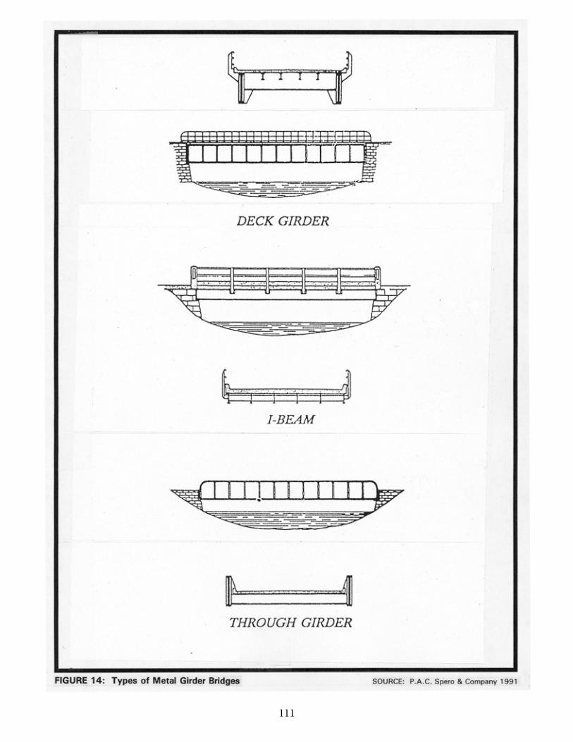
111104
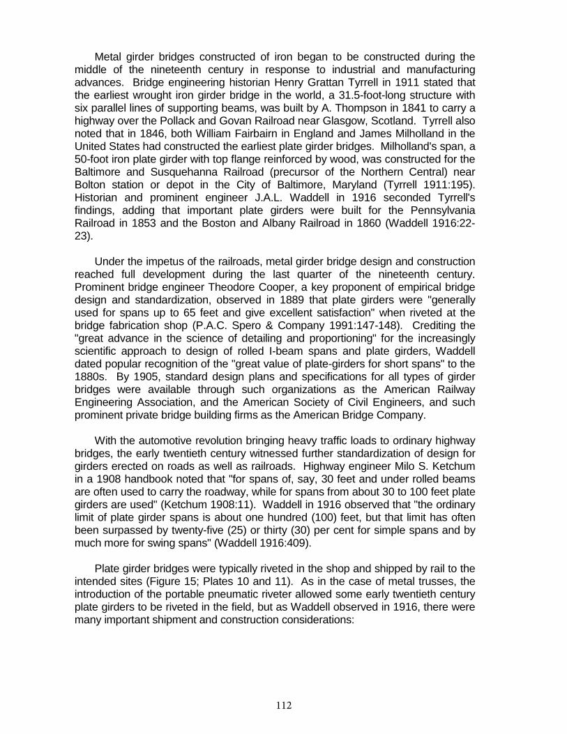
112
105
Metal girder bridges constructed of iron began to be constructed during the middle of the nineteenth century in response to industrial and manufacturing advances. Bridge engineering historian Henry Grattan Tyrrell in 1911 stated that the earliest wrought iron girder bridge in the world, a 31.5-foot-long structure with six parallel lines of supporting beams, was built by A. Thompson in 1841 to carry a highway over the Pollack and Govan Railroad near Glasgow, Scotland. Tyrrell also noted that in 1846, both William Fairbairn in England and James Milholland in the United States had constructed the earliest plate girder bridges. Milholland's span, a 50-foot iron plate girder with top flange reinforced by wood, was constructed for the Baltimore and Susquehanna Railroad (precursor of the Northern Central) near Bolton station or depot in the City of Baltimore, Maryland (Tyrrell 1911:195). Historian and prominent engineer J.A.L. Waddell in 1916 seconded Tyrrell's findings, adding that important plate girders were built for the Pennsylvania Railroad in 1853 and the Boston and Albany Railroad in 1860 (Waddell 1916:22-23).
Under the impetus of the railroads, metal girder bridge design and construction reached full development during the last quarter of the nineteenth century. Prominent bridge engineer Theodore Cooper, a key proponent of empirical bridge design and standardization, observed in 1889 that plate girders were "generally used for spans up to 65 feet and give excellent satisfaction" when riveted at the bridge fabrication shop (P.A.C. Spero & Company 1991:147-148). Crediting the "great advance in the science of detailing and proportioning" for the increasingly scientific approach to design of rolled I-beam spans and plate girders, Waddell dated popular recognition of the "great value of plate-girders for short spans" to the 1880s. By 1905, standard design plans and specifications for all types of girder bridges were available through such organizations as the American Railway Engineering Association, and the American Society of Civil Engineers, and such prominent private bridge building firms as the American Bridge Company.
With the automotive revolution bringing heavy traffic loads to ordinary highway bridges, the early twentieth century witnessed further standardization of design for girders erected on roads as well as railroads. Highway engineer Milo S. Ketchum in a 1908 handbook noted that "for spans of, say, 30 feet and under rolled beams are often used to carry the roadway, while for spans from about 30 to 100 feet plate girders are used" (Ketchum 1908:11). Waddell in 1916 observed that "the ordinary limit of plate girder spans is about one hundred (100) feet, but that limit has often been surpassed by twenty-five (25) or thirty (30) per cent for simple spans and by much more for swing spans" (Waddell 1916:409).
Plate girder bridges were typically riveted in the shop and shipped by rail to the intended sites (Figure 15; Plates 10 and 11). As in the case of metal trusses, the introduction of the portable pneumatic riveter allowed some early twentieth century plate girders to be riveted in the field, but as Waddell observed in 1916, there were many important shipment and construction considerations:
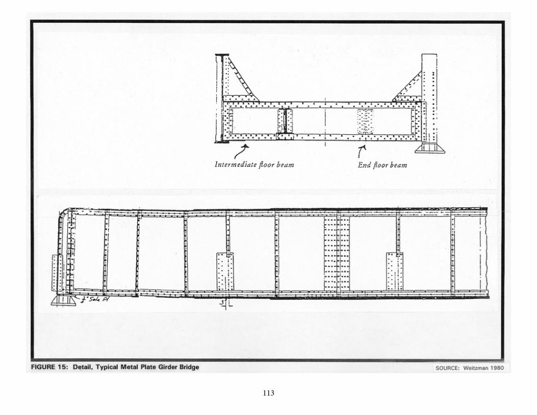
113106
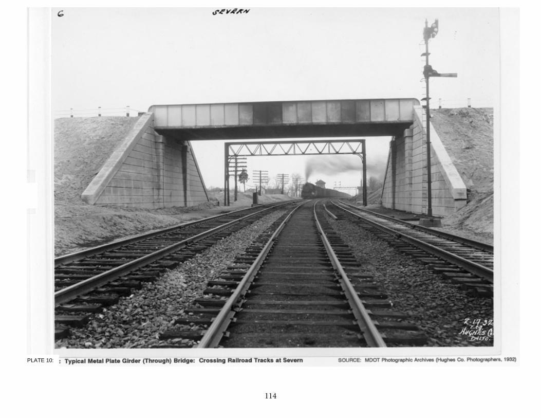
114107
PLATE 10:
115108
11:
116
109
Usually it is the difficulty of shipping very long plate-girders from bridge shop to site that determines the superior limit of such spans. The loading of long girders on cars for shipment is quite an art, and it should be entrusted only to men experienced in such loadings; for, otherwise, the metal is liable to be injured in transit or the cars break down. . . . About as long a plate-girder as has ever been shipped in one piece was one of one hundred and thirty-two (132) feet. It required four flat cars to transport it. Longer plate-girder spans than this have been built, notably tubular bridges and swing spans, but they were shipped in parts and assembled at site. This expedient for simple spans is really permissible only in case of bridges to be sent to foreign countries, and it is to be avoided if possible even then, because it is sometimes difficult to obtain a satisfactory job of field-riveting when making the splices, although the use of pneumatic riveters tends to reduce materially the force of this objection [Waddell 1916:409].
Further development in girder bridge technology between 1900 and 1930 was marked primarily by the spread of concrete-encased rolled I-beam structures, and by the introduction of the familiar mid-to-late twentieth century highway bridge in which deep steel beams support a deck of reinforced concrete. Victor Brown and Carleton Conner in their 1933 handbook Low Cost Roads and Bridges remarked on the adaptability and economy of the latter type of girder bridge:
With the introduction of the deep beam sections (30, 33, and 36 inches deep) now available, it has been possible to greatly simplify details of steel construction, particularly in the shorter span bridges. Spans of 60 to 100 ft. can be worked out, using available beam sections which will show considerable savings when compared with the older type low truss construction. . . .Where a concrete floor slab is used the beams are well protected from weather exposure and painting cost will be greatly reduced. . . .The beam spans have the further advantage that they can be widened or sidewalks added if this becomes necessary, whereas the pony truss spans cannot be widened [Brown and Conner 1933:506-507].
After the World War II hiatus on non-defense-related bridge construction ended in 1945, economical highway girder bridges such as those described by Brown and Conner were readily built by county and municipal officials across the United States. Technological advances in use of non-traditional metals, such as aluminum, also characterized some metal girder bridge design and construction after World War II. Although ALCOA in 1933 had designed a lightweight aluminum deck for the 1882 Smithfield Street Bridge in Pittsburgh, the earliest aluminum bridge in the United States was a 100-foot-long railroad plate girder span designed by ALCOA and built in 1946 to replace an existing bridge over the Grasse River, near Massena, New York (Trinidad 1984:1). Prior to this bridge, only a bascule bridge at Sunderland, England, and a Scottish footbridge had been made of aluminum (Alison 1984).

117
110
The Massena, New York, bridge and a 1950 long-span aluminum highway bridge at Arvida, Quebec, served to demonstrate the capabilities of aluminum as a structural material. Maryland's only known aluminum bridge is a girder bridge (Bridge # 13046) designed and built in 1963 by the State Highway Administration and International Aluminum Structures, Inc., to carry State Route 32 over the South Branch of the Patapsco River near Sykesville (Alison 1984; Suffness 1992a).
118
110
METAL GIRDER BRIDGES IN MARYLAND
Metal girder bridges were most likely introduced and first popularized inMaryland by the state's major railroads of the nineteenth century, including theBaltimore and Susquehanna, its successor the Northern Central, and the Baltimore and Ohio Railroad. As discussed, bridge engineering historians have documented the fact that James Milholland (or Mulholland) erected the earliest plate girder span in the United States on the Baltimore and Susquehanna Railroad in 1846 at Bolton Station, near present-day Mount Royal Station. The sides (web) and bottom flange of Milholland's 54-foot-long span were wholly of wrought iron and included a topflange reinforced with a 12x12-inch timber. Plates employed in the bridge were 6feet deep and 38 inches wide, giving the entire bridge a total weight of some 14tons. Milholland's pioneering plate girder cost $2,200 (Tyrrell 1911:195). ByDecember 31, 1861, the Northern Central Railroad, which succeeded the Baltimore and Susquehanna, maintained an operating inventory in Maryland of 50 or morebridges described simply as "girder" spans, in addition to a number of Howetrusses. Most of these were probably iron girder bridges; the longest were the117-foot, double-span bridge over Jones Falls and the 106-foot double-span girder bridge at Pierce's Mill (Gunnarson 1990:179-180).
Perhaps because girder bridge construction technology was not difficult andbecame readily standardized, few descriptions of nineteenth century deck girder or plate girder construction in Maryland have been located. One such account,however, serves to illustrate how plate girder bridges, initially employed onrailroads, became useful to Baltimore City engineers by the 1890s. In 1892,Frederick H. Smith, the prominent Baltimore Bridge Company partner then servingas a consulting engineer to the city, reported that the Campbell & Zell firm had been retained to build a new Lexington-Douglas Street bridge, which was to be "a deckbridge consisting of fourteen plate girders 78 feet long, reaching from wall to wall,and having curved tops upon which are riveted heavy floor plates carrying a granite block roadway 42 feet wide, and two granolithic sidewalks, each 14 feet wide, with heavy steel handrailings along their outer sides and granolithic gutter kerbing along their inner sides." Smith noted with some embarrassment that 13 of the 14 girders were in place, but the "scow with the one remaining girder is stranded in the mud a short distance below the bridge where she has been now for more than a weekawaiting the tides" (Baltimore City Commissioner 1892:489).
Girder bridge construction on the Baltimore and Ohio Railroad received a boost between 1901 and 1908, when former Pennsylvania Railroad Chief EngineerLeonor Loree took charge of a major rebuilding of the B&O main and branch lines.Aiming to refit the railroad so that it could safely run 2,500-ton coal trains behindheavy locomotives, Loree ordered construction of a combination deck girder andthrough truss bridge at the Ilchester tunnel, a seven-span deck plate girder bridgeover the Monocacy River, a girder replacement for the old Bollman truss overTuscarora Creek, and steel plate girder center spans for several trestles along the
119
111
B&O's Georgetown Branch in Montgomery County (Harwood 1979). Loree and his immediate predecessors also constructed many girder spans during the rebuildingof the Washington County Branch leading to Hagerstown) between 1890 and 1908 (Harwood 1979:375).
As in the nation, girder bridge technology in Maryland was quickly adapted tocope with the increasingly heavy traffic demands of the twentieth century caused by automobile and truck traffic. The 1899 Maryland Geological Survey report onhighways noted that "there are comparatively few I-beam bridges, one of thecheapest and best forms for spans less than 25 or 30 feet" (Johnson 1899:206).Interestingly, the report also urged construction of a composite metal, brick, andconcrete bridge, noting that "no method of construction is more durable than thecombination of masonry and I-beams, between which are transverse arches ofbrick, the whole covered with concrete, over which is laid the roadway" (Johnson1899:206). Whether any such bridges (transitional structures between I-beams and reinforced concrete spans) were built is unknown.
Official state and county highway reports--issued between 1900 and theearly 1920s through the Highway Division of the Maryland Geological Survey,and its successor, the State Roads Commission--generally do not reference ordescribe girder construction. An analysis of the current statewide listing ofcounty and municipal bridges (a listing maintained by the State HighwayAdministration) reveals that 48 county bridges, out of the total of 141approximately dated to "1900" by county engineers, were listed as steel girder,steel stringer, or variants of such terms. (It should be noted that the "1900" date is often given when no exact date is pinpointed for a bridge that is clearly old). A grand total of 200 bridges (including "steel culverts"), out of 550 bridges dated on the county list between 1901 and 1930, were described as steel beam, steelgirder, or steel stringer and girder varieties. The total suggests that metal girderbridges in Maryland between 1900 and 1930 were only less popular thanreinforced concrete bridges among the various highway bridge types built in theearly twentieth century. However, these numbers must be interpreted withcaution, as they do not necessarily include all county and municipal bridges.
Analysis of the more detailed 1993 Maryland State HighwayAdministration Bridge Inventory offers a portrait of historical patterns for thestate's extant metal girder bridges built between 1900 and 1940. The earlieststeel girder bridge listed on the state bridge inventory is the U.S. 11 bridge, a308-foot-long, three-span structure built in 1909 to carry the road over thePotomac River and the Western Maryland Railway. Only one steel girder orbeam structure, Bridge 3092 on State Route 147 over Long Green Creek, isdated between 1910 and 1920 (it is a single span of 37 feet built in 1915 andreconstructed or altered in unspecified fashion in 1969). Between 1921 and1930, however, 13 bridges now extant were built as steel girders or beams, orincorporated such spans. The latter category consisted of two significantmovable bridges constructed under state contracts (the 1924 Severn River
120
112
Bridge on State Route 450, featuring a double-leaf bascule along with steel beam spans, and the 1929 Bridge 2081 carrying State Route 436 over Weems Creek, a swing bridge with thirteen 20-foot steel beam spans). By 1921, most girderbridges erected by the State Roads Commission included reinforced concretedecks; as the inventory also clearly indicates, many girder bridges werestructures built to eliminate dangerous railroad grade crossings (MarylandDepartment of Transportation 1993a).
The 1930s saw continuation of these trends in girder construction. Morethan 40 steel girder or steel beam structures are listed on the state inventory asdating from the 1931-1940 period. Railroad grade crossing elimination continued to prompt the use of deck girder and half-through plate girder spans (theelimination program itself was given a welcome boost by New Deal planningsurveys sponsored in 1935-1940 by the U.S. Bureau of Public Roads).Improvement of such older roads as U.S. 1 (the Baltimore-WashingtonBoulevard) and construction of the new Pulaski Highway (U.S. 40) fromBaltimore to Perryville spurred construction of many steel girder highway spans.A singularly ornamented steel girder highway bridge in Maryland, extant as of1980-1981 (MHT-CE-998), is the U.S. 40 bridge over AMTRAK near Elkton, afour-span steel girder bridge, which appears to be concrete encased. The bridge parapets are highly ornamented with Art Moderne details. Until the World War II interruption of major bridge building, steel girder spans continued to be built inMaryland, under county, municipal, and state auspices.
A postwar trend in design of metal girder bridges, reflected in the 1963construction of a significant Maryland example, was the development ofaluminum girder bridges. Based on research alone, it appears that the 1963Bridge #13046, a three-span structure built by the State Roads Commission and International Aluminum Structures, Inc., is the only example of an aluminumbridge in Maryland and one of seven built in North America (Canada and UnitedStates) between 1948 and 1963. Bridge #13046 includes riveted triangular boxstiffened sheet girders supporting a light-weight concrete slab with a bituminouswearing surface (Alison 1984).
121
112
Conclusion
The following summary statements regarding structural characteristics formetal girder bridges, key periods of significance for metal girder bridges inMaryland, and the earliest known documented examples of metal girder bridges in the state are based solely on documentary research.
Metal girder bridges (see Figures 14 and 15 and Plates 10 and 11) arestructures in which a floor system and roadway are supported by parallel metalbeams or girders, which are carried by concrete, masonry, or metal supports(abutments or piers). The beams or girders are typically rolled sections, whichmay be plain or encased in concrete. The shape of the cross section of anindividual girder may define the girder as an I-beam, or a wide flange beam. Plate girders are characterized as girders built up of riveted sections, rather than asingle rolled section. Components of the girder are the flanges (horizontalportions) and the webs (vertical portions).
Girder bridges where the girders are located below the deck or roadway are termed deck girder bridges. Girder bridges in which the girders extend above theroadway level are through girders.
Key periods of significance for the metal girder bridge in Maryland, asindicated by documentary research, include 1846-1870, when this type of bridgewas introduced and popularized by the railroads as an economical and versatileexpedient; 1870-1920, when metal girder (especially plate girder) bridge designand construction was standardized and increasingly employed for highwaybridges; and 1920-1965, when the State Roads Commission utilized metal I-beams and metal plate girders (many concrete encased) heavily in construction for grade crossing elimination structures, as well as ordinary highway bridges.
The earliest known documented example of a metal girder bridge inMaryland was the 1846 plate girder erected by James Milholland on the Baltimore and Susquehanna Railroad, a span credited as the earliest bridge of this type built in the United States. The earliest metal girder bridge known to be extant inMaryland is the U.S. 11 Bridge over the Potomac River (Bridge #21001), built in1909 by the State Roads Commission. Other significant examples of metal girder bridges constructed in the state include Bridge #3092 on State Route 147 overLong Green Creek (single-span, 1915); the U.S. 40 bridge over AMTRAK nearElkton (four-span, with singularly ornamented Art Moderne detailing); and Bridge#13046, a three-span aluminum girder bridge built in 1963 on State Route 32 near Sykesville by the State Roads Commission and International Aluminum Structures, Inc. (this bridge is the only known aluminum bridge in Maryland).
122
114
SECTION VIII: METAL SUSPENSION, ARCH, AND CANTILEVER BRIDGES
Based on historical research and review of Maryland Historical Trust historic resource survey forms, it appears that few metal suspension, metal arch, and metal cantilever bridges are extant in Maryland. Structures exemplifying the development of these three bridge types, however, were built in the state from the beginning of the nineteenth century. Although there are few surviving nineteenth century suspension, metal arch, or cantilever bridges in the state, these structural types are well represented by important Maryland bridges built between 1940 and 1955. For this reason, each of these types deserves some discussion in any context for the evaluation of historic bridges in Maryland.
HISTORICAL DEVELOPMENT: METAL SUSPENSION BRIDGES
Many technological historians have asserted that the suspension bridge is one of the oldest bridge types in the world. There is documentation that such bridges were utilized in a range of non-Western ancient societies, notably in the Far East (Tibet, China) and South America (Peru and Bolivia, areas in the former Inca Empire). Such early bridges utilized the basic principle of suspension bridges--the hanging, or suspension, of a walkway or roadway from a rope or bundle of vines anchored at both ends. A major technological advance, attributed to Tibetan bridge builders, occurred when the walkway or roadway, previously laid directly on the rope or cable, was attached instead to hangers, or suspenders, between the rope or cable and the deck. Although this innovation meant that the anchor points had to be higher in order to bring the deck level with the proper grade of an existing approach roadway, the use of suspenders opened technology to possibilities for stiffening the deck, thereby decreasing the tendency of the bridge to swing or twist under loads or wind-generated force (Lay 1992).
As suspension bridge technology became more refined, a range of cable systems was developed (Figure 16). Chain links, wire ropes, and twisted strand cables (bundled and wrapped) were employed. Besides the cables, the roadway deck, and the suspenders, the basic components of a modern suspension bridge include towers, over which are draped the cables (held in place there by saddles or cradles), and heavy masonry abutments (or anchorages) where the cables descending from the tower tops are securely anchored. This typical design configuration results in division of the bridge into a main span and two side, or anchor, spans, with approach spans often of other structural types. Suspenders on the bridges (consisting of eyebars, rods, or steel ropes) are usually spaced at equal intervals and are vertical. On twentieth century structures,
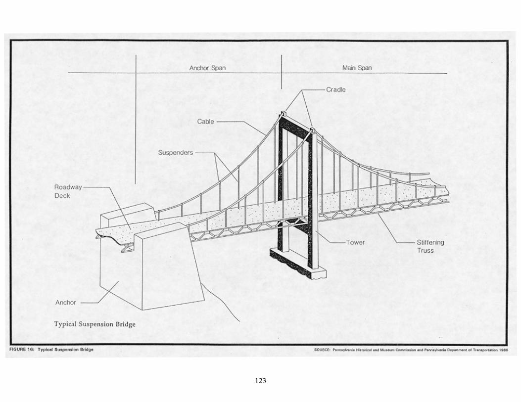
123
115
124
116
the suspenders usually connect to the cables by means of bolted bands. The tendency of suspension bridge cables to deflect (swing or twist under the application of loading) is typically counteracted by the stiffening of the deck with a truss system beneath it, although this system was preceded by use of long floor joists extending across several beams (Pennsylvania Historical and Museum Commission, and Pennsylvania Department of Transportation 1986:77).
Suspension bridges are highly significant in the history of American bridge technology because they were the earliest all-iron bridges constructed in the United States. Modern suspension bridge technology was largely pioneered by three distinguished suspension bridge builders active in the early nineteenth century, James Finley, Charles Ellet, and John A. Roebling. Finley, a judge and self-trained bridge constructor from Fayette County, Pennsylvania designed and built the first known suspension bridge in the United States over Jacob's Creek, at Uniontown, Pennsylvania, in 1801. Thereafter, some 40 Finley suspension spans were built. Finley's so-called "chain" bridges incorporated for the first time in the Western Hemisphere the use of suspenders to carry the deck at a level with the approaching roadway (Pennsylvania Historical and Museum Commission, and Pennsylvania Department of Transportation 1986:76-79).
The Finley spans were "chain" bridges because their cables were composed of wrought iron chains made of square bars, formed into links often ranging from 5 to 10 feet in length. Finley's Jacob's Creek span featured one-inch square bars, with vertical suspenders of varying lengths attached to each chain link and carrying the roadway's timber floor beams by means of a stirrup-like arrangement. Finley's earliest bridge was 13 feet wide and spanned 70 feet; later bridges he built, such as the famous 1807 "Chain Bridge" on the Potomac above Georgetown and a span constructed to his patent in about 1820 at Will's Creek near Cumberland in Maryland, were longer and wider, but generally followed the same chain-dependent design as his early spans. Construction of such chain bridges generally involved careful movement into place of the entire cables, which were lifted into position over the masonry towers and secured by various means to the abutments (Pennsylvania Historical and Museum Commission, and Pennsylvania Department of Transportation 1986:79).
Wire rope for cables was first employed in 1816, for a private toll footbridge over the Schuylkill built by Josiah White and Erskine Hazard, who were co-owners of a Philadelphia wire concern. In England in 1826, highway and bridge engineer Thomas Telford, aware of Finley's accomplishments, designed the first large-scale suspension bridge in the world, over the Menai Straits. Two years later, the world's first all-steel suspension span was erected over the Danube Canal in Vienna, anticipating twentieth century structures (DeLony 1993:2-3). Under the impetus provided by the Finley spans, the White-Erskine bridge, and the European suspension bridges of the 1820s, American suspension bridge design was again materially advanced by the contemporaries and occasional rivals in the field, Charles Ellet and John A. Roebling. Although the Erskine-White wire rope structure
125
117
had collapsed, wire rope spans were revived in the United States by Ellet, who had studied Europe's suspension bridges. In 1841-1842, Ellet's first major wire suspension bridge replaced Lewis Wernwag's covered timber "Colossus" bridge over the Schuylkill (Pennsylvania Historical and Museum Commission, and Pennsylvania Department of Transportation 1986:80).
Between 1846 and 1849, Ellet designed and built his most significant structure, the Wheeling suspension bridge at Wheeling, West Virginia, whose 1,100-foot span was for many years the longest in the world. Ellet's scholarly biographer, Gene Lewis, uncovered no evidence that any Ellet suspension bridges were built in Maryland, but it is certain that Ellet proposed in 1832 and again in 1854 to erect suspension spans over the Potomac on a scale equivalent to that of the Wheeling Bridge (Ellet 1854; Lewis 1968; Pennsylvania Historical and Museum Commission, and Pennsylvania Department of Transportation 1986:80). John Roebling also is not known to have designed and constructed any Maryland bridges, but his signal advance, the method of building a cable in place by "spinning" or "stringing" it using a traveling sheave, dramatically affected suspension bridge technology in the nineteenth and twentieth centuries. Roebling's bridges, such as his masterpiece the 1883 Brooklyn Bridge, largely built by his son Washington, had thick cables composed of such spun wires grouped into strands and then bound together in a circular geometric form. The cables were typically clamped at intervals for attachment of the suspenders (Pennsylvania Historical and Museum Commission, and Pennsylvania Department of Transportation 1986:82-83).
With adoption of the Ellet and Roebling techniques, twentieth century suspension bridge technology, like other types of bridge engineering, has been characterized by scientific analysis of suspension, stiffening, and anchoring principles, resulting in the design and construction of ever-larger suspension spans. During the mid-1920s, Allegheny County, Pennsylvania, Chief Engineer Vernon R. Covell designed three innovative Allegheny River suspension bridges at Pittsburgh. Lacking heavy anchorages or abutments, these spans were self-anchored because their cables at the ends were attached to a stiffening, underdeck truss system running the full length of the bridge. The stiffening truss acted like a compression member to resist the tension of the suspended cables. Covell's bridges also were the first major pin-connected eyebar chain bridges built since the previous century; their employment of eyebars, however, led to increased wear and was not generally followed in subsequent twentieth century bridge construction (Pennsylvania Historical and Museum Commission, and Pennsylvania Department of Transportation 1986:82-84).
Significant large suspension spans of the twentieth century include Othmar Ammann's 1931 George Washington Bridge, which reached a wire cable strength of 240,000 pounds per square inch (compared to the Brooklyn Bridge's 160,000 p.s.i); the 1937 Golden Gate Bridge designed by Joseph Strauss, with innovative cofferdams utilized to sink the pneumatic caissons into the bay floor; and New York City's 1964 Verrazano Narrows Bridge, also designed by Ammann, in which the

126
118
compacted cables are splayed into individual strands wrapping around massive eyebars embedded in the concrete anchorages. These bridges employed essentially the basic technology of suspension bridges in the United States, on a large scale, as pioneered by Finley, and especially Ellet and Roebling during the early nineteenth century (DeLony 1993:138-139, 143-145).
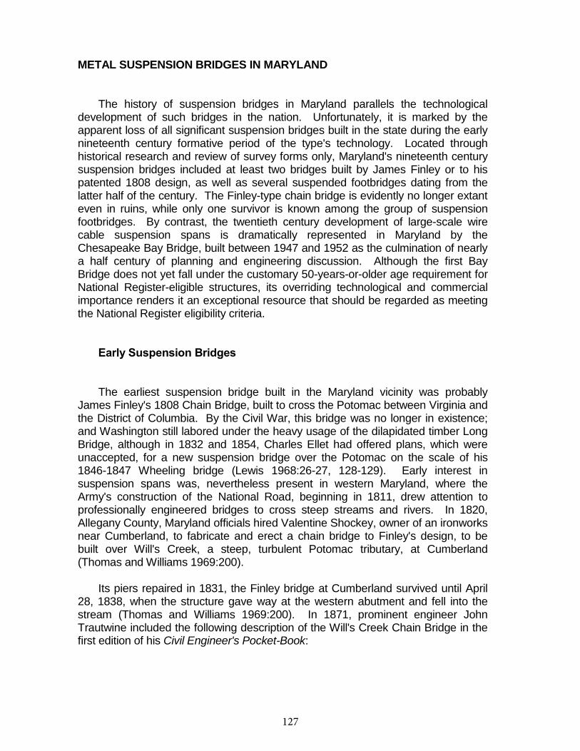
127
118
METAL SUSPENSION BRIDGES IN MARYLAND
The history of suspension bridges in Maryland parallels the technological development of such bridges in the nation. Unfortunately, it is marked by the apparent loss of all significant suspension bridges built in the state during the early nineteenth century formative period of the type's technology. Located through historical research and review of survey forms only, Maryland's nineteenth century suspension bridges included at least two bridges built by James Finley or to his patented 1808 design, as well as several suspended footbridges dating from the latter half of the century. The Finley-type chain bridge is evidently no longer extant even in ruins, while only one survivor is known among the group of suspension footbridges. By contrast, the twentieth century development of large-scale wire cable suspension spans is dramatically represented in Maryland by the Chesapeake Bay Bridge, built between 1947 and 1952 as the culmination of nearly a half century of planning and engineering discussion. Although the first Bay Bridge does not yet fall under the customary 50-years-or-older age requirement for National Register-eligible structures, its overriding technological and commercial importance renders it an exceptional resource that should be regarded as meeting the National Register eligibility criteria.
Early Suspension Bridges
The earliest suspension bridge built in the Maryland vicinity was probably James Finley's 1808 Chain Bridge, built to cross the Potomac between Virginia and the District of Columbia. By the Civil War, this bridge was no longer in existence; and Washington still labored under the heavy usage of the dilapidated timber Long Bridge, although in 1832 and 1854, Charles Ellet had offered plans, which were unaccepted, for a new suspension bridge over the Potomac on the scale of his 1846-1847 Wheeling bridge (Lewis 1968:26-27, 128-129). Early interest in suspension spans was, nevertheless present in western Maryland, where the Army's construction of the National Road, beginning in 1811, drew attention to professionally engineered bridges to cross steep streams and rivers. In 1820, Allegany County, Maryland officials hired Valentine Shockey, owner of an ironworks near Cumberland, to fabricate and erect a chain bridge to Finley's design, to be built over Will's Creek, a steep, turbulent Potomac tributary, at Cumberland (Thomas and Williams 1969:200).
Its piers repaired in 1831, the Finley bridge at Cumberland survived until April 28, 1838, when the structure gave way at the western abutment and fell into the stream (Thomas and Williams 1969:200). In 1871, prominent engineer John Trautwine included the following description of the Will's Creek Chain Bridge in the first edition of his Civil Engineer's Pocket-Book:
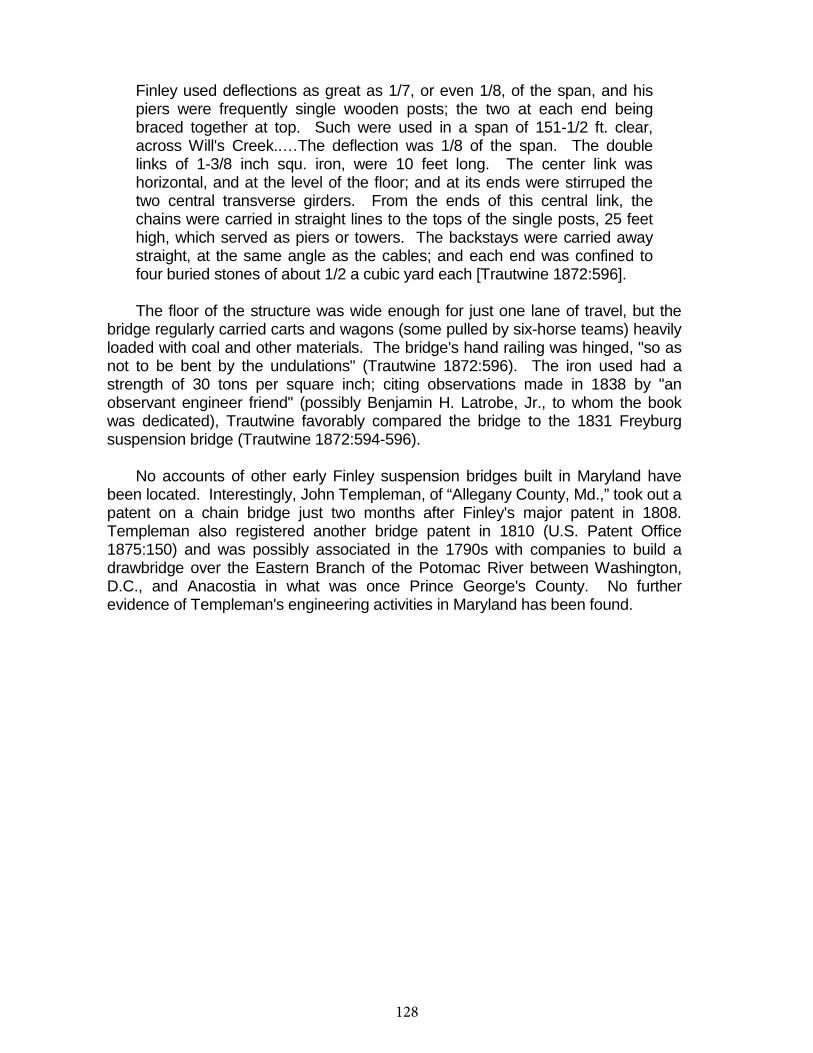
128
119
Finley used deflections as great as 1/7, or even 1/8, of the span, and his piers were frequently single wooden posts; the two at each end being braced together at top. Such were used in a span of 151-1/2 ft. clear, across Will's Creek..…The deflection was 1/8 of the span. The double links of 1-3/8 inch squ. iron, were 10 feet long. The center link was horizontal, and at the level of the floor; and at its ends were stirruped the two central transverse girders. From the ends of this central link, the chains were carried in straight lines to the tops of the single posts, 25 feet high, which served as piers or towers. The backstays were carried away straight, at the same angle as the cables; and each end was confined to four buried stones of about 1/2 a cubic yard each [Trautwine 1872:596].
The floor of the structure was wide enough for just one lane of travel, but the bridge regularly carried carts and wagons (some pulled by six-horse teams) heavily loaded with coal and other materials. The bridge's hand railing was hinged, "so as not to be bent by the undulations" (Trautwine 1872:596). The iron used had a strength of 30 tons per square inch; citing observations made in 1838 by "an observant engineer friend" (possibly Benjamin H. Latrobe, Jr., to whom the book was dedicated), Trautwine favorably compared the bridge to the 1831 Freyburg suspension bridge (Trautwine 1872:594-596).
No accounts of other early Finley suspension bridges built in Maryland have been located. Interestingly, John Templeman, of “Allegany County, Md.,” took out a patent on a chain bridge just two months after Finley's major patent in 1808. Templeman also registered another bridge patent in 1810 (U.S. Patent Office 1875:150) and was possibly associated in the 1790s with companies to build a drawbridge over the Eastern Branch of the Potomac River between Washington, D.C., and Anacostia in what was once Prince George's County. No further evidence of Templeman's engineering activities in Maryland has been found.
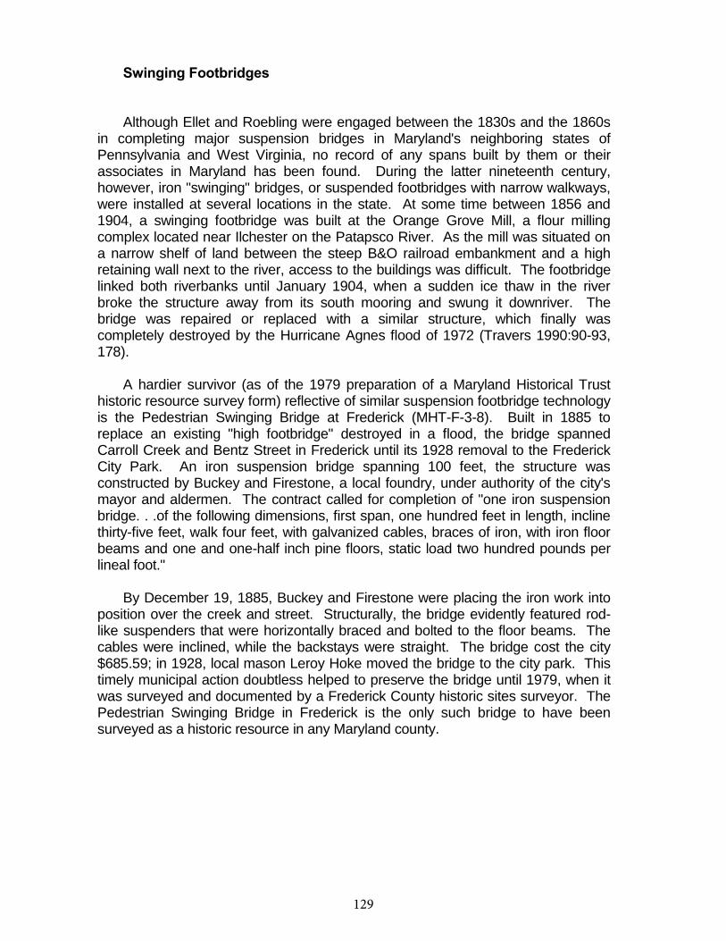
129
120
Swinging Footbridges
Although Ellet and Roebling were engaged between the 1830s and the 1860s in completing major suspension bridges in Maryland's neighboring states of Pennsylvania and West Virginia, no record of any spans built by them or their associates in Maryland has been found. During the latter nineteenth century, however, iron "swinging" bridges, or suspended footbridges with narrow walkways, were installed at several locations in the state. At some time between 1856 and 1904, a swinging footbridge was built at the Orange Grove Mill, a flour milling complex located near Ilchester on the Patapsco River. As the mill was situated on a narrow shelf of land between the steep B&O railroad embankment and a high retaining wall next to the river, access to the buildings was difficult. The footbridge linked both riverbanks until January 1904, when a sudden ice thaw in the river broke the structure away from its south mooring and swung it downriver. The bridge was repaired or replaced with a similar structure, which finally was completely destroyed by the Hurricane Agnes flood of 1972 (Travers 1990:90-93, 178).
A hardier survivor (as of the 1979 preparation of a Maryland Historical Trust historic resource survey form) reflective of similar suspension footbridge technology is the Pedestrian Swinging Bridge at Frederick (MHT-F-3-8). Built in 1885 to replace an existing "high footbridge" destroyed in a flood, the bridge spanned Carroll Creek and Bentz Street in Frederick until its 1928 removal to the Frederick City Park. An iron suspension bridge spanning 100 feet, the structure was constructed by Buckey and Firestone, a local foundry, under authority of the city's mayor and aldermen. The contract called for completion of "one iron suspension bridge. . .of the following dimensions, first span, one hundred feet in length, incline thirty-five feet, walk four feet, with galvanized cables, braces of iron, with iron floor beams and one and one-half inch pine floors, static load two hundred pounds per lineal foot."
By December 19, 1885, Buckey and Firestone were placing the iron work into position over the creek and street. Structurally, the bridge evidently featured rod-like suspenders that were horizontally braced and bolted to the floor beams. The cables were inclined, while the backstays were straight. The bridge cost the city $685.59; in 1928, local mason Leroy Hoke moved the bridge to the city park. This timely municipal action doubtless helped to preserve the bridge until 1979, when it was surveyed and documented by a Frederick County historic sites surveyor. The Pedestrian Swinging Bridge in Frederick is the only such bridge to have been surveyed as a historic resource in any Maryland county.
130
121
The First Chesapeake Bay Bridge
No suspension bridges built between 1890 and 1952 are known to be extant in Maryland. Nonetheless, the state holds an outstanding example of modern suspension bridge technology, the first Chesapeake Bay Bridge, built in 1947-1952 by the J.E. Greiner Company under agreement with the Maryland State Roads Commission. Design and construction of the Bay Bridge climaxed almost 50 years of debate and discussion, and fully represented the latest techniques and engineering innovations in mid-twentieth century American suspension bridge engineering design.
The earliest public proposal for bridging the Chesapeake Bay in Maryland was in 1907, when various merchants and manufacturers' associations of Maryland sponsored consideration of the issue. The result was the 1908 Hoen Committee report, which recommended engineering studies. Westinghouse, Church, Kerr & Company, consulting engineers, found construction of a bridge a feasible solution, but costly at more than 13 million dollars. In 1918, the state legislature authorized the State Roads Commission to establish auto ferry service between Annapolis and Claiborne on the Eastern Shore; such service went into effect in 1919.
Further unsuccessful attempts to incorporate and finance Bay Bridge companies culminated between 1926 and 1938 in the activities of the ill-starred Chesapeake Bay Bridge Company, which suffered a loss of some $300,000. (The J.E. Greiner Company, which had been retained as consultants by the Chesapeake Bay Bridge Company, would ultimately construct the bridge.) The Depression forced consideration of public financing rather than private bond issues for the project, and in 1937 the State Roads Commission was directed to formulate a plan for the erection of four "primary bridges" needed in Maryland: the Bay Bridge, a bridge to carry U.S. 301 into Virginia, a span to take U.S. 40 across the Susquehanna at Havre de Grace, and a proposed Baltimore Harbor crossing (which in 1957 was finally opened as the first Harbor tunnel, rather than a bridge). The resultant 1938 Primary Bridge Program report became the basis for construction of the Bay Bridge at the Sandy Point-Kent Island site (Hamill 1952).
Army Corps of Engineers' navigational restrictions impelled construction of the Bay Bridge on a curved alignment crossing; the alignment to be followed was normal to the ship sailing course approximately 1 1/2 miles south of Sandy Point Lighthouse. The 4.03-mile-long bridge consisted of a total of 123 fabricated steel spans including the central cable suspension span, its side spans, and a series of cantilever trusses, simple trusses, and plate girder and beam spans. The suspension span over the "Main Sailing Course" (the Bay channel) was 1,600 feet long, with towers rising 354 feet above the bay surface. The 28-foot (curb-to-curb) roadway deck at the main span cleared the water surface by 198 1/2 feet; vertical ship clearance in the 1,500-foot waterway beneath the main span was 186 1/2 feet. The suspension cables installed on the bridge were 14 inches in diameter.
131
122
Construction of the Chesapeake Bay Bridge began in 1947 and ended in 1952. Permanent steel form or "Potomac Type" piers (so-called because they were first employed in construction of the 1940 U.S. 301 Bridge between Maryland and Virginia) were utilized for Piers 11 through 40 (except for Piers 23 and 28); these were built by excavating below the bay bottom, then driving temporary piles to support a wooden platform at the pier bottom, with openings for each permanent pile. The latter were driven through such openings, whereupon permanent steel forms, prefabricated and incorporating pier-reinforcing steel, were lowered to the platforms. Piers 23 and 28, the cable anchorage piers for the suspension span cables, were built by cofferdam methods, and sand and rock islands were constructed below water level adjacent to the anchorages in order to protect them from potential ship collision. Except for the suspension span, the steel superstructure was erected mostly by floating components into place below their intended positions, then hoisting them by derrick or traveler cranes mounted on the already-built spans as they progressed out from the shore. Testifying to the Roebling tradition of tower construction as employed for the Brooklyn Bridge and other spans, the towers for the Bay Bridge were built using special traveling booms (Chicago booms), one on each leg of a tower, which worked in pairs to raise the steel tower sections (and themselves) as the height increased. A traveling sheave arrangement was also employed to build the cables to their full diameter and span length, while workers on a temporary footbridge (also a device utilized by Ellet and Roebling) adjusted the strands for proper lay. The stiffening trusses for the main span, prefabricated in Baltimore and floated into position, were lifted into place by engines powering a secondary cable system attached to the bridge's suspension cables. Vertical suspenders were then attached to the trusses, and the permanent wire cables were wrapped by machine with No. 9 galvanized steel wire before being coated with zinc chromate.
On July 30, 1952, Governor Theodore McKeldin ceremonially opened the bridge, christened the William Preston Lane Memorial Bridge after McKeldin's predecessor, who had done much to secure its construction. McKeldin called the bridge a "friendly device and a valuable utility" and predicted that it would be among the most traveled spans in the United States. Fulfilling that prediction, the Chesapeake Bay Bridge has served continuously since 1952, augmented in the mid-1970s by the addition of a second parallel structure (Maryland State Roads Commission 1952a:1-32).
132
122
Conclusion
The following summary statements regarding structural characteristics for metal suspension bridges, key periods of significance for metal suspension bridges in Maryland, and the earliest known documented example of metal suspension bridges in the state are based solely on documentary research.
Metal suspension bridges (see Figure 16) consist of a suspended superstructure, with many components, which is anchored into a masonry or concrete substructure. The basic structural system consists of flexible cables with stiffening trusses or girders suspended from them which carry the deck system. Suspension bridges may comprise various combinations of cables, towers, suspenders, and girders or trusses added to stiffen the bridge against wind and load stresses. In a typical suspension bridge, towers are built upon the piers, and the cables are carried high above the deck in cradles located at the top of the towers. The cables run downward to anchor spans from the towers of the main span; cables are usually anchored in heavy concrete or masonry abutments or anchorages. The deck is carried by suspended stiffening structures, girders or trusses, which serve to stiffen the truss against swaying or deflection.
Prior to the development of wire-rope cable technology, earlier suspension bridges featured cables consisting of chains formed from linked eyebars. Eyebar chain suspension bridges continued to be built in the twentieth century in some regions of the United States.
Key periods of significance for metal suspension bridges in Maryland, as indicated by documentary research, include 1800-1840, the formative era of suspension bridge development within the United States, during which the basic technology of wrought iron "chain" bridges was pioneered by James Finley and associates (one known example is a bridge built to Finley's design is known to have been erected over Will's Creek at Cumberland in 1820 by Valentine Shockey); and 1900-1960, a period in which the wire rope suspension bridge technology, perfected by Charles Ellet and John Roebling during the nineteenth century, was refined and saw dramatic application in Maryland's first Chesapeake Bay Bridge, completed between 1942 and 1952 but planned by the State Roads Commission prior to World War II. Documentary research has also located evidence of "swinging" pedestrian footbridges built in Maryland during the 1850-1900 period; no such bridges, however, are known to have been constructed for highway use.
Maryland's only known major suspension bridge is the Chesapeake Bay Bridge, a monumental wire rope span built 1947-1952 by state authorities and designed by J.E. Greiner Company. No highway-related suspension bridges from the nineteenth century are known to have survived: field survey, which may locate such bridges or their remnants (e.g., abutments or piers), will be necessary to verify this conclusion.
133
123
HISTORICAL DEVELOPMENT: METAL ARCH BRIDGES
Like metal suspension bridges, arch bridges of iron and steel evolved in form from early types built in traditional materials. Metal arch bridges may be usefully classified by degree of articulation (type of pinned connection found at the bridge supports and at its midpoint or arch crown) or by the form or configuration of the arch employed. In a fixed, or hingeless, metal arch structure, the ends of the main spans are embedded in large supports (abutments or piers). When articulated with a pinned connection at each support (a method utilized to allow the bridge some movement under rotational forces), the bridge is a two-hinged arch. When end supports are pinned and another hinge or pin is located at or near the arch crown or midpoint, the structure becomes three-hinged. Rarely built, the one-hinged variant employs a single pinned connection near mid-span at the arch crown.
Three major varieties of metal arch bridge, categorized by type of arch configuration, may be. Solid-ribbed arches are constructed of plate girder ribs cast in a curved form. The deck of such a structure is carried on metal posts resting on top of the arches, or (if the bridge is a through, or bowstring, arch) from suspenders hung from the arch bottoms (Figure 17; Plate 12). Solid-ribbed arches were built in hingeless, one-hinged, two-hinged, and three-hinged variants. By contrast, the brace-ribbed arch features two parallel, or near-parallel, arch chords linked by a system of open webbing consisting of truss members (hence, a second name for this subtype is the trussed arch). Brace-ribbed structures were similarly erected in all hingeless and hinged variants.
The third basic subtype by arch configuration, the spandrel-braced arch, is characterized by the roadway or deck carried atop the arch (hence, these structures are deck arches). The main arch of a spandrel-braced arch consists of its curved bottom members. The roadway is carried on the horizontal top chord, while a web trussing system, typically composed of Pratt trusses, links the top chord to the arch (Pennsylvania Historical and Museum Commission, and Pennsylvania Department of Transportation 1986:93-94).
Adapting the familiar arch form of stone bridges, metal arch technology first developed in England as a result of the mid-eighteenth century advances in the iron industry. The earliest iron bridge in the world, Ironbridge at Coalbrookdale in England, was built in 1781 and consisted of five semicircular cast-iron arch ribs with a 300x150-millimeter rectangular cross section. The eminent American revolutionary writer Thomas Paine designed an iron arch featuring a linked array of block-shaped cast iron voussoirs, but this configuration did not readily attract backers and was not regularly employed. The English pioneer in highway engineering, Thomas Telford, advanced metal arch technology considerably during the late eighteenth and early nineteenth century, with his design and construction of a number of flat (high span-to-rise ratio)
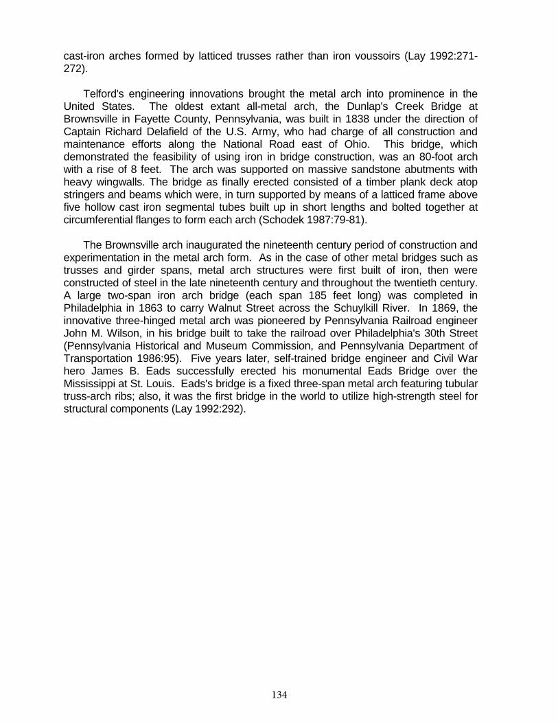
134
124
cast-iron arches formed by latticed trusses rather than iron voussoirs (Lay 1992:271-272).
Telford's engineering innovations brought the metal arch into prominence in the United States. The oldest extant all-metal arch, the Dunlap's Creek Bridge at Brownsville in Fayette County, Pennsylvania, was built in 1838 under the direction of Captain Richard Delafield of the U.S. Army, who had charge of all construction and maintenance efforts along the National Road east of Ohio. This bridge, which demonstrated the feasibility of using iron in bridge construction, was an 80-foot arch with a rise of 8 feet. The arch was supported on massive sandstone abutments with heavy wingwalls. The bridge as finally erected consisted of a timber plank deck atop stringers and beams which were, in turn supported by means of a latticed frame above five hollow cast iron segmental tubes built up in short lengths and bolted together at circumferential flanges to form each arch (Schodek 1987:79-81).
The Brownsville arch inaugurated the nineteenth century period of construction and experimentation in the metal arch form. As in the case of other metal bridges such as trusses and girder spans, metal arch structures were first built of iron, then were constructed of steel in the late nineteenth century and throughout the twentieth century. A large two-span iron arch bridge (each span 185 feet long) was completed in Philadelphia in 1863 to carry Walnut Street across the Schuylkill River. In 1869, the innovative three-hinged metal arch was pioneered by Pennsylvania Railroad engineer John M. Wilson, in his bridge built to take the railroad over Philadelphia's 30th Street (Pennsylvania Historical and Museum Commission, and Pennsylvania Department of Transportation 1986:95). Five years later, self-trained bridge engineer and Civil War hero James B. Eads successfully erected his monumental Eads Bridge over the Mississippi at St. Louis. Eads's bridge is a fixed three-span metal arch featuring tubular truss-arch ribs; also, it was the first bridge in the world to utilize high-strength steel for structural components (Lay 1992:292).
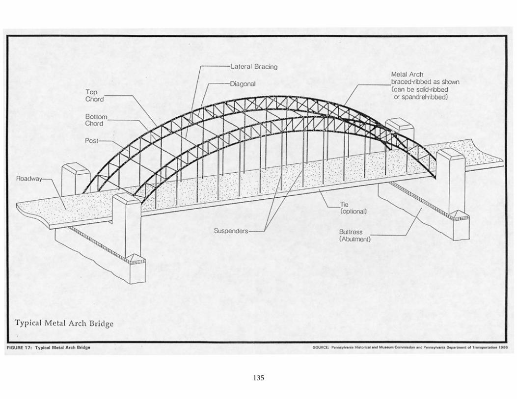
135125
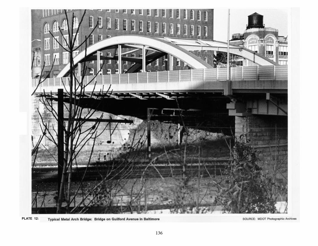
136126
PLATE 12:
137
127
Bowstring metal arches, in which the arch ribs ascend above the roadway deck, became popular under the impetus of the metal bridge innovations of such engineers as Squire Whipple and Thomas Moseley. Prior to the Civil War, Whipple built bowstring arch bridges over the Erie Canal and patented a design which, though essentially a truss bridge, nonetheless relied on the inherent strength of its arched upper chord (see report section entitled "Metal Truss Bridges" for further discussion of Whipple's work with arch truss structures). Bowstring bridges incorporating features of the metal arch as well as the metal truss were frequently built during the latter half of the nineteenth century by many of the same bridge companies (such as the King Bridge Company of Canton, Ohio) that popularized Pratt and Warren trusses. In most instances, field survey alone can determine precisely whether these structures relied primarily on a truss system for support, they were essentially metal arches utilizing suspended verticals or trusses to support the roadway deck.
By 1890, the three-hinged metal arch had gained general acceptance as a suitable structure for highway bridges. Metal arch bridges in the United States during the late nineteenth and early twentieth centuries were primarily utilized in highway construction, as the railroads usually preferred metal truss bridges to carry the generally heavier loads of locomotives and trains. Perhaps the best known and most significant major metal arch bridge of the early twentieth century is the Hell Gate Bridge, a massive two-hinged through arch designed by master bridge engineer Gustav Lindenthal and built in 1914-1916. Lindenthal's Hell Gate Bridge has a clear arch span of a remarkable 977 feet; the upper chord is curved and is connected to the arch rib by a network of Pratt trusses, which together with the chord serves to stiffen the bridge against traffic and wind pressures (Pennsylvania Historical and Museum Commission, and Pennsylvania Department of Transportation 1986:94-96).
More modest metal arch bridges continued to be built in the United States during the first half of the twentieth century. The aesthetic, classic appeal of the arch form, often a public consideration in design of stone arch and concrete arch bridges, also frequently made metal arches an attractive twentieth century alternative. J.A.L. Waddell in his 1916 Bridge Engineering noted that "where steel construction is adopted, attempts are being made to obtain the best possible appearance, either by means of the arch (the ideal solution when practicable) or by polygonal top chords, which tend to produce a graceful effect" (Waddell 1916:16).
In a 1912 article, however, bridge engineer and reinforced concrete arch pioneer Daniel B. Luten cautioned that "in steel bridges, the arch is difficult to fabricate and difficult to erect, and consequently steel trusses and girders have a distinct advantage" (Luten 1912:631). Although metal arch bridges in the modern, automotive era did not attain the general versatility and adaptability of steel girder and reinforced concrete structures, the metal arch form remains a significant

138
128
American historic bridge type, displaying a technological continuity of development in the United States similar to that of the more common metal truss bridges.
139
128
METAL ARCH BRIDGES IN MARYLAND
Metal arch bridges in Maryland do not comprise a large group of historicstructures, but do include representative examples from both the nineteenth andthe twentieth centuries. No early iron arch bridges are known to have beenconstructed on the Maryland section of the historic National Road, althoughNational Road maintenance inspired Captain Delafield to build the nationallysignificant Dunlap's Creek Bridge in 1838. The spread and popularity of the metal arch form in Maryland appear to have occurred primarily in the years following theCivil War, as iron and steel making technology rapidly progressed and bridgebuilding firms were founded to take advantage of a ready, growing market for metal highway spans. Small, pony bowstring arch-truss bridges were marketed by suchfirms as the King Iron Bridge Company and the Smith Bridge Company to countycommissioners in Maryland. As already noted, such structures were essentiallycombination structures, and could adequately function in quite different waysalthough their appearance remained the same. In some structures, the archedupper member might serve primarily as an arch connected by a truss system to the bottom horizontal chord of the bridge, while in other bridges the trusses might bethe primary components and simply feature an arched top chord.
Dating mainly from the 1870s and 1880s, Maryland's known dated latenineteenth century examples of the metal bowstring truss bridge include three pony spans and one larger through bridge, the Waverly Street Bridge at Williamsport(documented as HAER No. MD-83). The three pony spans recorded on priorsurvey forms are the Crum Road Bridge over Israel Creek in Frederick County(MHT-F-2-5; a circa 1875 King Iron Bridge Company product), the Bennies HillRoad Bridge over Catoctin Creek in Frederick County (MHT-F-2-2; also made bythe King firm in about 1880), and Bridge #51 in the Whitaker Mill Historic District in Harford County (MHT-HA-1237; a bowstring arch-truss with Warren trussconfiguration of undetermined date). Only further field investigation of thesestructures can adequately determine whether they are primarily metal arch bridges, or pony trusses with arched upper chords, or a combination design.
While many Maryland county authorities found bowstring arch-truss bridgesdesirable during the last quarter of the nineteenth century, there is also ampleevidence that Baltimore City constructed a number of important metal arch bridges between 1880 and 1900, a period which saw the 1888 annexation of a largesurrounding area by the city. Few if any of these urban structures appear to havesurvived (the last known to have been taken down was the Cedar Avenue Bridge), yet they mark a significant chapter in the employment of the arch form in Maryland bridge building. Two familiar Baltimore City metal through arch bridges of thetwentieth century, the Howard Street and Guilford Avenue bridges built over Jones Falls and railroad tracks during the 1930s, attest to the visual presence of the city's late nineteenth century metal arches, as both of these twentieth century bridges
140
129
were designed to conform with the built landscape of a group of through archesthen crossing the Jones Falls and the tracks.
Many of the city's early metal arch bridges over Jones Falls were built underthe auspices of the Jones' Falls Improvement Commission, which in 1878 hiredprominent Baltimore Bridge Company partner Charles H. Latrobe as consultingengineer. Latrobe's first accomplishment for Baltimore in metal arch bridge design was the Calvert Street Bridge, 579 feet long and consisting of two bowstring arch-truss spans of wrought iron with two viaduct approaches (Baltimore CityCommissioner 1882:694). The fourth bridge erected under Jones' FallsImprovement Commission authority was the St. Paul Street Bridge, a 703-foot-long,two-hinged wrought iron, through arch structure with two through metal arch spans of 110 and 280 feet. This was the largest of all the bridges erected by theCommission between 1878 and 1882 (most of the others were metal truss bridges) (Baltimore City Commissioner 1882:393).
Latrobe's first two metal arch bridges for the city survived well into the twentieth century but were ultimately replaced as traffic loads on Calvert and St. Paul Streets increased. The Calvert Street Bridge, built at the time on the edge of the settledcity limits, was pronounced by Mayor Ferdinand Latrobe (Charles Latrobe's uncle)a "suitable place to promenade for persons visiting the suburbs" (Nottrodt 1983).The four ornamental lions guarding the bridge were damaged on December 2,1883 by Irish-American Larry Finnegan, who protested British rule of Ireland bytaking an ax to the lions' tails (Nottrodt 1983). Charles Latrobe's next major metalarch bridge project for Baltimore City, the Cedar Avenue Bridge built in 1889-1890,departed from the pattern of wrought iron bowstring arches and two-hinged through arches to adopt a deck arch design. The Cedar Avenue Bridge, crossing theNorthern Central Railroad, the Jones Falls valley, and Falls Road, featured a three-ribbed, three-hinged steel trussed-arch 150 feet in length, with side spans carriedby three lines of Warren deck trusses (Vogel 1975:16).
Latrobe, in his 1890 report to the city commissioner, offered further instructivedetails regarding the Cedar Avenue Bridge and its construction. The superstructure was fabricated by the King Iron Bridge and Manufacturing Company of Cleveland,Krug & Son of Baltimore erected the ornamented hand railing, and the masonrywork was done by Jones and Thorne of Baltimore. Incidentally indicating that theWarren deck truss side spans were not original to the bridge, Latrobe's description of the structure outlined why he chose a metal arch for the site:
Owing to the solid rock at Jones' falls at this point, I concluded that a brace arch would be well adapted to the main span, and would certainly presenta more graceful appearance than a rectangular truss. This being settled,girders were used for the side spans, so that the bridge as built consists of a braced arch span one hundred and fifty feet long over the water, aseventy-two-foot latticed girder over the Falls road at the eastern end, aseventy-two-foot latticed girder at the western end over the Northern
141
130
Central Railway, and thence two plate girders twenty-four feet six incheseach to reach the western abutment, which stands in Druid Hill Park[Baltimore City Commissioner 1890:936-937].
The Cedar Avenue Bridge opened a key crossing into the newly annexed Druid Hill neighborhoods; Latrobe did not know of "any recent improvement within the Citylimits which has been of more use to those who live within its influence" (Baltimore City Commissioner 1890:937).
Charles Latrobe's three major Baltimore metal arches were not immediatelyfollowed by similar structures, either in the city or in Maryland generally. The record of metal arch construction in the state resumed in the 1930s, when Baltimoremunicipal engineers and State Roads Commission officials again concentrated onimprovement of key downtown crossings of the Jones Falls valley and adjacentrailroad tracks. On December 23, 1935, the State Roads Commission awarded acontract, with Federal Public Works Administration (P.W.A) aid and approval, to the American Bridge Company to furnish a two-span, three-hinged, tied steel archbridge to replace the 1879 truss bridge carrying Guilford Avenue over thePennsylvania Railroad (see Plate 12). Complete with United Electric Railwaystrolley tracks and protective metal and glass screens to prevent persons fromclimbing up the surface of the arches, the Guilford Avenue Bridge opened onNovember 2, 1936 (Baltimore City Department of Public Works 1936:252).
Between 1937 and 1939, a second similar bridge, also designed by the Bridge Division of the Baltimore Department of Public Works, was built in downtownBaltimore to carry Howard Street over the B&O and Pennsylvania Railroad tracks.Built with P.W.A. funds and labor like the Guilford Avenue arch and many otherMaryland bridges of the 1930s, the Howard Street Bridge featured two three-hinged, tied steel arch spans of 270.4 and 270.67 feet respectively, with plate girder side spans (Baltimore City Department of Public Works 1937:245-246). TheHoward Street Bridge opened for traffic in early 1939 (Baltimore City Department of Public Works 1938:232).
Subsequent to construction of the Guilford Avenue and Howard Street spans in Baltimore, only two other mid-twentieth century through steel arch bridges areknown to have been built in Maryland. In 1942, the vertical lift movable bridgecrossing the Chesapeake and Delaware Ship Canal at Chesapeake City wasdestroyed during a collision with a freighter. Wartime priorities postponedreplacement of this bridge until 1948, when a new Chesapeake City Bridge, a high-level, two-lane tied arch structure with steel hangers, was constructed (Gray1985:261,289). Maryland's other documented mid-twentieth century metal archbridge is the Blue Bridge, a two-span tied through arch built in 1955 under StateRoads Commission authority to cross the Potomac between Cumberland andRidgely, West Virginia (Leviness 1958:137; Maryland State Roads Commission1956b:61). A search of all official reports of the Maryland State Roads Commission

142
131
for the 1900-1960 period located no further references to design and constructionof metal arch bridges in Maryland.
143
131
Conclusion
The following summary statements regarding structural characteristics for metal arch bridges, key periods of significance for metal arch bridges in Maryland, andthe earliest known documented examples of metal arch bridges in the state arebased solely on documentary research.
Metal arch bridges (see Figure 17 and Plate 12) consist of two (or more)parallel arches of iron or steel spanning between masonry or concrete piers orabutments. The arch member may be a curved girder or may include a trusssystem between curved top and bottom chords. Other components include lateral bracing, and columns or hangers for supporting the deck and floor system.
If the deck is suspended from the arch by means of vertical suspenders, thearch is termed a through arch. If the deck is carried atop the arch crown, the bridge is a deck arch structure. The deck may also be suspended or carried at variousintermediate levels, allowing for half-through variants. If a tension member (or tie)is included between the ends of the span, the arch thrust is carried through this tie, and the bridge is a tied arch.
Arch bridges may also be grouped according to the degree of articulation of the arch. A fixed arch is a hingeless arch, but hinges may be included in the one-hinged variant (a single hinge at the top center, or crown, of the arch), the two-hinged variant (hinges at the points where the arch joins the abutments), and thethree-hinged variant (hinges at crown of arch and at abutments).
As indicated by documentary research, key periods of significance for metalarch bridges in Maryland include 1870-1900, during which time metal bowstringarch-truss bridges (pony spans as well as through bridges with overhead portals)were built within the state, and Charles Latrobe and Associates designed andconstructed several major bowstring arches and deck arch bridges for the Jones'Falls Improvement Commission of the City of Baltimore and 1930-1960, the period in which Baltimore City authorities built tied, three-hinged steel "Rainbow" archbridges over the Jones Falls (1936, 1939), and the State Roads Commissionconstructed metal tied through arches at Chesapeake City (1948) and Cumberland (1955).
The earliest known examples of metal arch bridges in Maryland may be agroup of bowstring arch pony truss bridges built on county roads in the state during the 1870s (several examples are known from prior surveys conducted in Frederick and Harford Counties). Field survey alone, however, can reveal whether thesestructures are primarily metal arch bridges, or pony trusses with arched upperchords, or a combination design. Other known significant examples of metal archbridge design in Maryland include "Rainbow" arches (metal arch structures with

144
132
through bowstring arches featuring overhead bracing), built by Baltimore City andthe State Roads Commission between 1930 and 1960.
145
132
CANTILEVER BRIDGES: THE GOVERNOR HARRY W. NICE MEMORIAL BRIDGE
From a technical perspective, cantilever construction of a bridge defines aspecific form of support of the bridge rather than a particular bridge type such asthe truss or girder. Simply supported bridges are directly supported on piers andabutments, while continuous structures, as developed in both metal and reinforced concrete during the late nineteenth and early twentieth centuries, include spans that are continuous across one or more intermediate supports. By contrast, thecantilever form of support occurs when the support is at one end and the other end of the span is free. Cantilever bridges consist of a series of cantilevered spansincluding a main span and two anchor spans which flank it (Pennsylvania Historical and Museum Commission, and Pennsylvania Department of Transportation1986:124).
Based on historical research alone, cantilever bridges in Maryland appear to be represented by only one bridge, which may be briefly described in order to provide historic technological context for the evaluation of that bridge, the 1940 GovernorHarry W. Nice Memorial Bridge carrying U.S. 301 over the Potomac River.
Bridge historian J.A.L. Waddell noted that "the development of the cantilever. . . did not proceed very far until modern times, when the truss form of structure hadbecome established and when iron and steel constituted the materials ofconstruction" (Waddell 1916:7). Waddell and subsequent technological historiansdated the major advent of modern cantilever bridges to the design and construction of the high bridge over the Kentucky River at Dixville in 1876-1877. This bridgewas built by Charles Shaler Smith of the Baltimore-based Baltimore BridgeCompany. (for more information on Smith's firm, see the section of this reportentitled "Metal Truss Bridges") (Schodek 1987:362). During the late nineteenth andearly twentieth centuries, cantilever design and construction of other long-spanmetal bridges in the United States followed Smith's breakthrough.
Historical research has found no records of nineteenth or early twentiethcentury cantilever bridge construction in Maryland, by Smith's company or anyother bridge firms or public authorities. The only known bridge in Maryland to have employed a cantilever system is the 9,918.84-foot-long Governor Harry W. NiceMemorial Bridge, built between 1938 and 1940 as part of the state's "primary bridge program" that also envisioned construction of the Chesapeake Bay Bridge, the first Baltimore Harbor Tunnel, and the Susquehanna River highway bridge at Havre de Grace (J.E. Greiner Company 1938). In 1938, when construction on the bridge had just begun, main designer and contractor J.E. Greiner Company offered thefollowing description of the bridge as it was to be built:
The main channel span and the two side spans flanking it, comprise acantilever unit, the main span of which is 800 feet long and the side spans of which are anchor spans each 366 feet 8 inches long. The cantileverunits forming the approaches to the central unit are made up of alternate
146
133
anchor spans and cantilever spans 437 feet 6 inches and 500 feet longrespectively. The main section of the bridge is approached from theVirginia end by sixty-three spans of concrete pile bent and steel beamtrestle construction 3873 feet long, and four plate girder spans 100 feetlong, connecting the trestle with the main cantilever unit. On the Maryland side of the river, the main cantilever section of the bridge is approached by three 100 feet plate girder spans and two 250 feet simple truss spansconnecting the filled approach, with the main cantilever section [J.E.Greiner Company 1938:99-101].
The bridge was built to carry U.S. 301 in a key commercial link betweenSouthern Maryland and Virginia's Northern Neck, which hitherto had traded goodsonly by ship or roundabout highway or train transport. Thus, the Governor Harry W.Nice Memorial Bridge is significant as a major example (perhaps Maryland's onlyexample) of modern cantilevered bridge engineering, and is also important because of its strategic economic usefulness as part of the successful Primary BridgeProgram of the Maryland State Roads Commission.

147
134
Conclusion
The following summary statements regarding structural characteristics for metal cantilever bridges, the single documented example of a metal cantilever bridge in Maryland, and the key period of significance for this bridge type in the state are based solely on documentary research.
Cantilever bridges are defined by the structural support of the bridge rather then the individual configuration of the structural elements. Cantilever structures contrast with simply supported structures: simply supported structures are directly supported at each end, while cantilevered structures are directly supported at one end and free at the other end. Cantilever bridges consist of two anchor arms (directly supported on two piers), two cantilever arms (directly supported on one end by the anchor pier), and a central suspended span which is carried by the two anchor arms. Metal cantilever bridges may typically include cantilevered truss or girder spans.
The only known metal cantilever bridge in Maryland, as indicated by documentary research, is the Governor Harry W. Nice Memorial Bridge, carrying U.S. 301 over the Potomac River since its construction in 1940 by J.E. Greiner Company under contract to the State Roads Commission. Further field investigation, however, will be necessary to adequately document this conclusion. The period of significance for the Governor Harry W. Nice Memorial Bridge is 1900-1940, the era in which the construction of large metal cantilever bridges was introduced and technologically developed for highway use at major crossings in the United States.
148
135
SECTION IX: CONCRETE BRIDGES
HISTORICAL DEVELOPMENT
Concrete bridges constitute the greatest number of Maryland's known historic bridges. Technologically, the development of concrete bridges is an important chapter in the history of bridge building, being the application of a rediscovered material to both traditional and new forms and largely supplanting the metal truss bridge in the spanning of short and medium distances. Aesthetically, concrete bridge design introduced a greater level of decorative treatment, as the plastic nature of concrete allowed variety and ease of construction for these decorative details. Although the greatest number of concrete bridges are the results of standardized designs, there are many concrete bridges that feature stylistic embellishment.
Although used for building by the ancient Romans, the modern rediscovery of concrete as a common building material was a nineteenth century phenomenon, with reinforced concrete developing in the late nineteenth and early twentieth centuries (Plowden 1974:297). In bridges, concrete was first used as a construction material in plain or unreinforced concrete structures. The first applications of the material were to the arch bridge, a design developed (like concrete itself) by the Romans and used, in its masonry form, in great numbers in early years of this nation. An early example of the application of concrete to the arch bridge in the United States was the 1871 Prospect Park Bridge in Brooklyn, New York (Armstrong 1976:115; Plowden 1974:297). Within two decades, the understanding of material behavior quickly had progressed to the composite use of concrete and steel, often termed "ferro-concrete."
The addition of iron reinforcement to masonry structures had been used in isolated cases for centuries, since the nature of masonry as a compressive material with inherent weaknesses in tension was appreciated by ancient engineers. The interaction of the two materials remained to be studied by late nineteenth and early twentieth century engineers (Plowden 1974:297). The incipient theoretical understanding of metal utilized to reinforce concrete in the new plastic masonry was realized by an American experimenter, Thaddeus Hyatt (1816-1901), who began to study reinforced concrete's possibilities in the 1850s and received a patent for reinforced concrete in 1878 (American Society of Civil Engineers 1976:65). However, it was French and German engineers who first studied and tested the principles of steel reinforcement for tensile stresses in concrete arches in the 1880s. A serious obstacle to the use of concrete arches was the unknown character of their behavior
149
136
under live loads. From 1890 to 1895 the Austrian Society of Engineers and Architects conducted extensive experiments on full-size concrete arches and the results were published in engineering journals throughout Europe and America (Plowden 1974:298).
In 1889, prior to the publication of the Austrian reinforced concrete arch tests, the first reinforced concrete arch in the United States was built in Golden Gate Park, San Francisco. Designed by Ernest L. Ransome, it was reinforced with rods or bars, possibly of the twisted type patented by Ransome in 1884 (Armstrong 1976:115; Plowden 1974:298). Early concrete bridge development included experimentation with different forms of steel reinforcing. Bar reinforcement became the predominant type used in the early twentieth century, and is the reinforcement type encountered today; however, the predominant type through the end of the nineteenth century employed beams rather than bars. The I-beam type was introduced by Austrian engineer Joseph Melan, who patented a scheme for arched I-beam reinforcement in the United States in 1894. Melan's design was modified and patented by another Austrian engineer, Fritz von Emperger, who built a number of beam-reinforced arch bridges in the United States beginning in 1897 (Plowden 1974:298).
Beam reinforcement was soon recognized as requiring an inordinate amount of steel, and bar reinforcement began to be explored as a more efficient use of material. Bars could be bent and placed in regions of high tensile stresses, thus saving enormous quantities of materials while producing stronger bridges with lower dead loads. Many variations in shapes, patterns of surface deformation (provided to maintain the adhesion between the bars and the concrete), and bending schemes were developed and patented (Plowden 1974:298).
Among the American engineers who contributed to the development of reinforced concrete bridge technology during this formative period was Edwin Thacher (1840-1920). An 1863 civil engineering graduate of Rensselaer Polytechnic Institute, Thacher became interested in steel-reinforced concrete construction in the late 1880s, and by 1895 had made this a specialty. He designed and constructed viaducts and bridges for leading southern railroads during the period 1889-1904. Also during that period, he became the western representative of Fritz von Emperger's company, and was instrumental in disseminating the Austrian engineer's technological innovations in the United States. In partnership with W.H. Keepers, he designed the first major reinforced concrete bridge in the United States, a three-span Melan-type concrete arch with imbedded steel truss bars over the Kansas River at Topeka. Erected between 1894 and 1899, this structure was the largest of its kind at the time (Plowden 1974:299).
Thacher developed an improved reinforcing bar. Throughout the development of reinforced concrete technology, engineers sought methods of
150
137
improving the adhesion between the reinforcing steel and the concrete surrounding it. Their efforts generally involved various deformations to the surface of the bar, such as the "projections" called for in Thacher's 1899 patented design. Ernest L. Ransome patented the first deformed reinforcing bar in 1884, which aimed to increase the mechanical connection between the steel and the concrete by twisting the bar. The "Thacher Bar" (U.S. Patent No. 714,971) was designed as an elongated bar with longitudinally oriented cross-shaped deformations integrally formed on the upper and lower surfaces. This configuration enabled the reinforcing steel to remain uniform in net section throughout the bar, ensuring that the strength of the bar would be the same at every point and that no unnecessary metal would be used in its manufacture. In addition, sharp corners were minimized during manufacture, so that the bond between the bar and the concrete would be further improved. William Mueser, Thacher's associate in the Concrete-Steel Engineering Company, credited the bar as the first product of its type to achieve its final shape by a direct rolling process. The Thacher bar, like those used in current concrete design, was available in a range of sizes, starting at 1/4 inch and increasing in 1/8-inch increments to 2 inches.
With growing confidence, bridge engineers made increasing use of reinforced concrete. In an 1899 Engineering News article, "Concrete Steel Bridge Construction," Thacher, who held patents for iron as well as concrete bridges, exemplified early enthusiasm for concrete. He wrote of concrete-steel bridges:
They are more beautiful and graceful in design, architectural ornamentation can be applied as sparingly or as lavishly as desired; they have vastly greater durability, and generally greater ultimate economy; they are comparatively free from vibration and noise; they are proof against tornadoes, high water or fire; the cost of maintenance is confined to the pavements, and is no greater than for any other part of the street; home labor is employed in building it, and the greater part of the money that it costs is left among the people who pay for it, and its cost as a rule does not much, if any, exceed that of a steel bridge carrying a pavement. . . .Public confidence in concrete and concrete-steel construction, is gaining rapidly in this country and in Europe, where there is plenty of precedent, and where the people have been more thoroughly educated up to it, there has been no lack of confidence in it for some years. . . .We hear nothing now from intelligent men about mud bridges [Thacher 1899].
Although scientifically understood with some degree of sophistication in the 1890s, concrete began to be used more widely and in a more structurally efficient manner in the United States after the first decade of the twentieth century. In 1903-1904 the American Society of Civil Engineers formed its Joint
151
138
Committee on Concrete and Reinforced Concrete in an attempt to standardize concrete design. Their first report was published in 1909. In 1916, the Committee on Reinforced Concrete Highway Bridges and Culverts of the American Concrete Institute (ACI) issued its first report which classified highway bridges and recommended appropriate design loads. According to bridge engineer-historian Tyrrell, between 1894 and 1904 about 100 concrete bridges had been built in the United States in spans up to 125 feet (Tyrrell 1911), and in 1916 Waddell claimed that "for city bridges of short span its use is becoming almost universal" (Waddell 1916), with other wide applications noted.
The development of prestressed concrete has increased the usefulness of concrete in modern bridge design. Prestressing entails the application of a permanent load to the concrete through tensioned cables to increase its load-bearing capacity. The principle was developed in Europe during the 1930s and first applied in America to the 160-foot-long Walnut Lane Bridge erected in Philadelphia in 1949 (Plowden 1974:321). Guided by the Bureau of Public Roads' 1955 Criteria for Prestressed Concrete Bridges, the use of prestressed concrete in bridge design was rapidly taken up throughout the nation. The technique has found wide application in the construction of precast concrete members used on overpasses of the interstate highway system (Armstrong 1976:117).
152
138
Concrete Arch Bridges
The advent of modern concrete technology fostered a renaissance of archbridge construction in the United States. Stone arch bridges constitute animportant chapter in American bridge building, but by the second half of thenineteenth century the labor-intensive nature of masonry arch bridge constructioncontrasted unfavorably with the ease of metal truss erection. Reinforced concrete allowed the arch bridge to be constructed with much more ease than ever beforeand maintained the load-bearing capabilities of the form. Accompanying the return of the arch form were the traditional architectural decorative details that had beenin abeyance during the heyday of the truss bridge. It is interesting that therenaissance of the arch bridge and its decorative elements coincides with thereintroduction of the beaux arts aesthetics following the 1893 ColumbianExposition.
Concrete arch bridges are classified into four groups based on the way thedead load of the structure is carried. The four groups are (1) filled spandrel, (2)closed spandrel, (3) open spandrel, and (4) through arches. The filled spandrelarch consists of a barrel arch which carries filling material and terminates in closed longitudinal walls that act as retaining walls for the fill. Both closed and openspandrel arch types carry the roadway loads to the arch ribs and contain no fill.The former type carries the deck loads by spandrel walls resting on the arch ribs,while the latter type carries the roadway loads to the arch ribs by spandrelcolumns. Through arches consist of ribs which extend above the roadway andcarry the deck loads by vertical hangers (Plates 13 and 14).
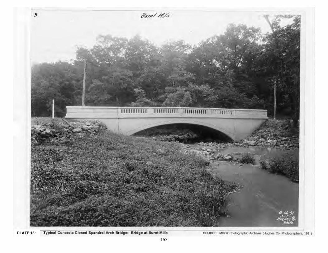
153139
PLATE 13:
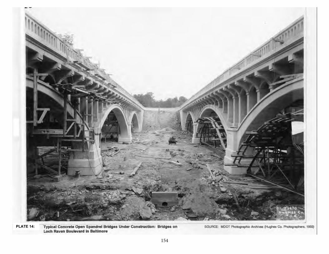
154140
PLATE 14:
155
141
Early concrete arch bridges were governed by building traditions of theirpredecessor, the stone arch. They were shaped as traditional masonry barrelswith solid, filled arches; surface treatment of important bridges incorporatedstylistic "stones" such as incised voussoirs or keystones. The first knownreinforced concrete arch bridge in the United States was designed by Ernest L.Ransome and built in 1889 in Golden Gate Park, San Francisco (Armstrong1976:115; Plowden 1974:298). It was reinforced with rods or bars, probably ofthe twisted type patented by Ransome in 1884, and scored to imitate stone.
As the structural advantages of reinforced concrete became apparent, the heavy, filled barrel was lightened into ribs. Spandrel walls were opened, to givea lighter appearance and to decrease dead load. This enabled the concrete arch to become flatter and multi-centered, with longer spans possible. Designerswere no longer limited to the semicircular or segmental arch form of the stonearch bridge.
The variety of arch types made possible through reinforced concretedesign is exemplified by the designs of Daniel B. Luten, whose patented bridges were built throughout the eastern and midwestern United States. Luten was an1894 civil engineering graduate of the University of Michigan. Upon graduationhe was retained at Michigan as an instructor and assistant to Professor CharlesE. Greene, whose arch analyses were noted in the ASCE Transactions. From1895 to 1900, Luten was instructor of civil engineering at Purdue University andin 1900 he resigned to design bridges. One year later he was designing andpatenting his designs.
In 1899, Luten applied for a patent for an arch bridge of concrete, stone,brick, iron, or steel in which ties were placed below the water, from abutment toabutment to resist the arch thrust, and the patent was granted on May 15, 1900.His ties, "which may be made of any material—as wood, iron, or steel—but in this case are shown as being made of wood or timber, as this is the best materialnow known to me for the purpose, it being practically everlasting when usedunder water." This concept developed into his patent for a tied concrete arch inwhich steel tie rods were embedded in a concrete pavement across thestreambed. A 1906 text on reinforced concrete by Albert Buel described Luten'ssteel-tied, paved arch bridge.
Luten's 1907 patent No. 857,920 shows a barrel arch with recessed panel parapet walls and a similar "flat arch or girder" type design with the same parapet detail. A similar patent of 1907 lightened the bridge dead load with openspandrels but maintained a barrel arch.
In 1907, Luten patented another arch type which reinforced the arch barrel transversely as well as longitudinally. In effect, this design was a stiffened
156
142
spandrel which permitted thinner arch sections. Included in this patent wereseveral variations, one of which made parapet walls act with the superstructureto carry the loads. In patent No. 853,203, this variation was described as follows:
A concrete bridge having a roadway bordered by a concrete wall, a longitudinal reinforcing member embedded in the walls, andtransverse reinforcing members embedded in the wall andextending into the bridge under the roadway.
Other Luten patents, totaling over 30, included numerous variations,among them a hinged arch and viaducts; systems of reinforcement; ingeniouscentering forms and methods; methods of bridge construction; and reinforcedconcrete beams.
Daniel Luten was also an enthusiastic salesman of his bridge designs,emphasizing their advantages both in company catalogs and at professionalpresentations. In the American Concrete Institute Proceedings of 1912, hepraised concrete arches:
Concrete as a structural material is full of surprising possibilities and one of these is that the most beautiful and appropriate applications of concrete to bridges, that is in the arch form, is also the mostsatisfactory from almost every engineering standpoint [Luten1912:631].
Luten's first bridge company was the National Bridge Company,established in 1902. A 1914 Luten publication stated that until 1905 the National Bridge Company did the contracting and constructing of its bridges, but after that it was involved only in engineering design and supervision. In 1907, a companycatalog advertised a variety of earth-filled arches reinforced with steel rods. Itclaimed that the company had designed more than 700 bridges of this type. Aninteresting arch type included in this 1907 catalog was the "arch-girder" bridge,described as a flat arched floor supported on five girders.
By 1911, Luten had won national attention, and was singled out by bridge historian Henry Grattan Tyrrell as a "designer and builder of many fine concretebridges throughout America" (Tyrrell 1911).
Luten and other bridge engineers designing concrete arch spans weredirectly influenced by the City Beautiful movement, an early twentieth centuryeffort to advocate construction of public and municipal structures that wereaesthetically pleasing yet still functional. The increasing popularity of gracefullycurved arches and ornamented concrete parapets also reflected the earlytwentieth century promotion of City Beautiful ideas and goals among urbanplanners, highway engineers, and motorists' groups like the AmericanAutomobile Association and the Lincoln Highway Association.
157
143
A 1917 publication entitled Reinforced Concrete Bridges by Daniel B. Luten,"designing and consulting engineer," illustrated a broader range of arch types,although still based on the same theme as his earlier designs. In this catalog,bridge illustrations ranged from long-span, high-level open spandrel arches tosmall highway bridges. Luten contrasted a "Highway Bridge of Plain Design"with a "Park Bridge of Attractive Design" in the same publication. The parapetwall of the highway bridge was a solid recessed panel and that of the park bridge a balustrade type (Luten 1917).
By 1919, Luten claimed to have designed some 17,000 arches, and stated that examples of his designs could be found in all but three states of the Union.Indiana alone had some 2,000 Luten arches. Luten arch bridges known to have been built in Maryland often featured curved, simply ornamented solid parapets.Characterized by the graceful arch and curved, incised solid parapets, this bridge type was described in Luten Company catalogs as "Highway Bridge of PlainDesign." This type of concrete arch was widely built as a proprietary type in thefirst quarter of the twentieth century. Luten's "Park Bridge of Attractive Design"also influenced concrete arch design in Maryland. Variations in the Luten stylearch and parapet detail soon developed and resulted in similar nonproprietarydesigns prepared by highway department staffs.
Simultaneous with the development of Luten's patented types, anotherform of reinforced arch rib emerged, the through arch. The two arch ribs of thistype rise from piers and carry the deck on vertical members suspended from their crowns. They are sometimes referred to as "Rainbow Arches" and sometimes as "Marsh Arches" after German-born engineer, Marsh, who patented his througharch and built it between 1912 and 1930.
The procedure for constructing concrete arch bridges was roughly similarto that used for stone arches. In the first phase the foundations, abutments, andpiers were constructed. Next, temporary bracing or centering, also used asforms for the concrete, was erected followed by placement of reinforcement. The concrete was then placed in the forms symmetrically from each end moving intoward the crown. Longer spans, more than 80 feet, had to be poured insections, but shorter spans could be completed in one pour. The spandrel walls, posts, or arches were formed after the arch ring was completed. The centeringwas gradually released after the concrete had set sufficiently, usually within thestandard twenty-eight days but depending on conditions. After the formwork was removed the concrete surface was finished according to various methods.Sometimes a facing was applied as in brick or stone. Often monumental bridges had surface treatments imitating stone. If the surface was to be left exposedthen it was either rubbed to produce a smooth surface or worked with tools toproduce a texture.
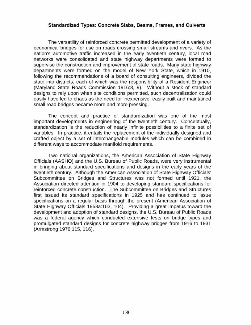
158
144
Standardized Types: Concrete Slabs, Beams, Frames, and Culverts
The versatility of reinforced concrete permitted development of a variety of economical bridges for use on roads crossing small streams and rivers. As the nation's automotive traffic increased in the early twentieth century, local road networks were consolidated and state highway departments were formed to supervise the construction and improvement of state roads. Many state highway departments were formed on the model of New York State, which in 1910, following the recommendations of a board of consulting engineers, divided the state into districts, each of which was the responsibility of a Resident Engineer (Maryland State Roads Commission 1916:8, 9). Without a stock of standard designs to rely upon when site conditions permitted, such decentralization could easily have led to chaos as the need for inexpensive, easily built and maintained small road bridges became more and more pressing.
The concept and practice of standardization was one of the most important developments in engineering of the twentieth century. Conceptually, standardization is the reduction of nearly infinite possibilities to a finite set of variables. In practice, it entails the replacement of the individually designed and crafted object by a set of interchangeable modules which can be combined in different ways to accommodate manifold requirements.
Two national organizations, the American Association of State Highway Officials (AASHO) and the U.S. Bureau of Public Roads, were very instrumental in bringing about standard specifications and designs in the early years of the twentieth century. Although the American Association of State Highway Officials' Subcommittee on Bridges and Structures was not formed until 1921, the Association directed attention in 1904 to developing standard specifications for reinforced concrete construction. The Subcommittee on Bridges and Structures first issued its standard specifications in 1925 and has continued to issue specifications on a regular basis through the present (American Association of State Highway Officials 1953a:103, 104). Providing a great impetus toward the development and adoption of standard designs, the U.S. Bureau of Public Roads was a federal agency which conducted extensive tests on bridge types and promulgated standard designs for concrete highway bridges from 1916 to 1931 (Armstrong 1976:115, 116).
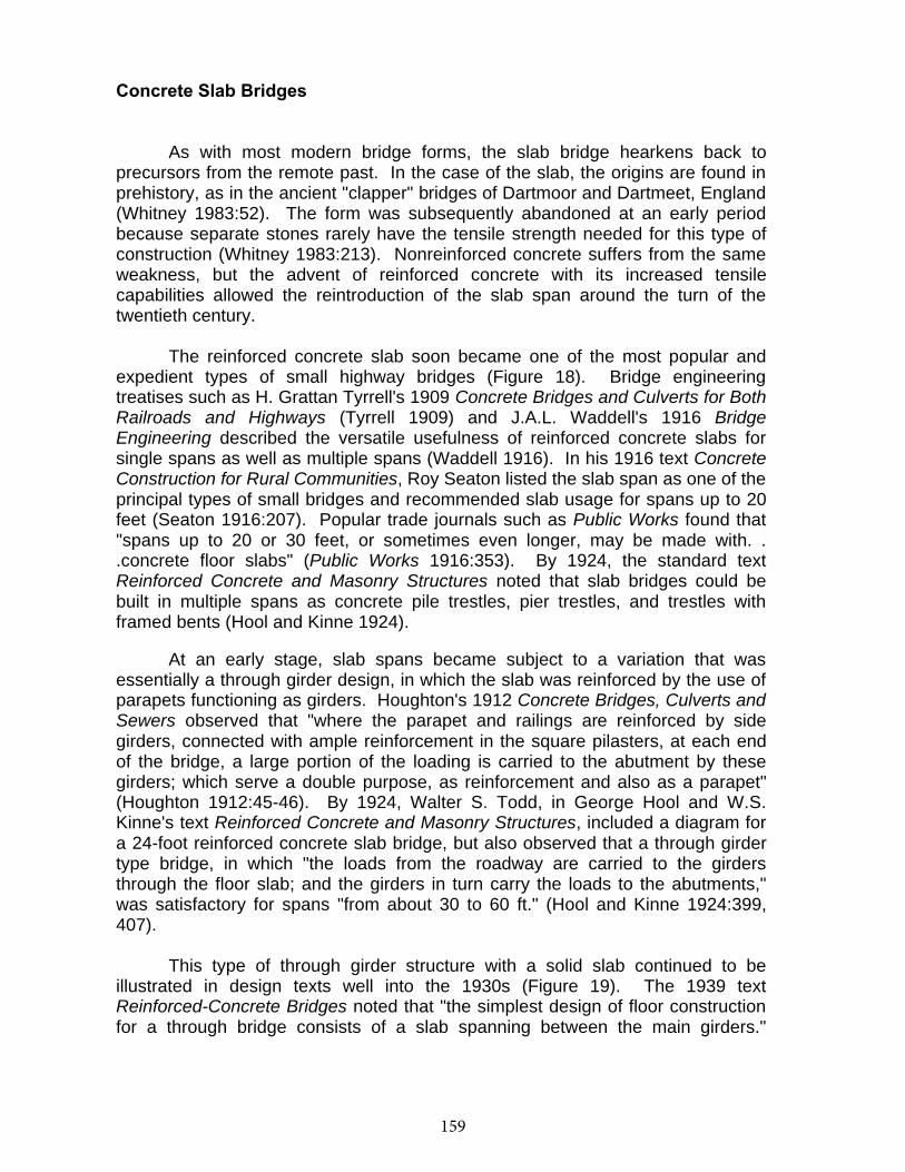
159
144
Concrete Slab Bridges
As with most modern bridge forms, the slab bridge hearkens back toprecursors from the remote past. In the case of the slab, the origins are found inprehistory, as in the ancient "clapper" bridges of Dartmoor and Dartmeet, England (Whitney 1983:52). The form was subsequently abandoned at an early periodbecause separate stones rarely have the tensile strength needed for this type ofconstruction (Whitney 1983:213). Nonreinforced concrete suffers from the sameweakness, but the advent of reinforced concrete with its increased tensilecapabilities allowed the reintroduction of the slab span around the turn of thetwentieth century.
The reinforced concrete slab soon became one of the most popular andexpedient types of small highway bridges (Figure 18). Bridge engineeringtreatises such as H. Grattan Tyrrell's 1909 Concrete Bridges and Culverts for Both Railroads and Highways (Tyrrell 1909) and J.A.L. Waddell's 1916 BridgeEngineering described the versatile usefulness of reinforced concrete slabs forsingle spans as well as multiple spans (Waddell 1916). In his 1916 text ConcreteConstruction for Rural Communities, Roy Seaton listed the slab span as one of the principal types of small bridges and recommended slab usage for spans up to 20feet (Seaton 1916:207). Popular trade journals such as Public Works found that"spans up to 20 or 30 feet, or sometimes even longer, may be made with. ..concrete floor slabs" (Public Works 1916:353). By 1924, the standard textReinforced Concrete and Masonry Structures noted that slab bridges could bebuilt in multiple spans as concrete pile trestles, pier trestles, and trestles withframed bents (Hool and Kinne 1924).
At an early stage, slab spans became subject to a variation that wasessentially a through girder design, in which the slab was reinforced by the use of parapets functioning as girders. Houghton's 1912 Concrete Bridges, Culverts and Sewers observed that "where the parapet and railings are reinforced by sidegirders, connected with ample reinforcement in the square pilasters, at each endof the bridge, a large portion of the loading is carried to the abutment by thesegirders; which serve a double purpose, as reinforcement and also as a parapet"(Houghton 1912:45-46). By 1924, Walter S. Todd, in George Hool and W.S.Kinne's text Reinforced Concrete and Masonry Structures, included a diagram fora 24-foot reinforced concrete slab bridge, but also observed that a through girdertype bridge, in which "the loads from the roadway are carried to the girdersthrough the floor slab; and the girders in turn carry the loads to the abutments,"was satisfactory for spans "from about 30 to 60 ft." (Hool and Kinne 1924:399,407).
This type of through girder structure with a solid slab continued to beillustrated in design texts well into the 1930s (Figure 19). The 1939 textReinforced-Concrete Bridges noted that "the simplest design of floor constructionfor a through bridge consists of a slab spanning between the main girders."

160
145
Observing that "such arrangement is economical only for narrow bridges" because "the dead load would be excessive" in wider crossings, the text's authors included diagrams for a typical "slab spanning between girders" (Taylor et al. 1939:94).
A variation of the slab design that was developed in the 1930s was thecontinuous slab bridge, in which a single slab extends over several spans. By 1939,structures with spans of slab up to 70 feet had been designed. Although thedesign has some advantages, including simpler arrangement of reinforcement and better distribution of lateral and longitudinal loading, the greater cost of materialsand larger dead loads reduced its advantages over the simply supported multiple-span slab bridge (Taylor et al. 1939:35).
In both its simple and continuous span forms, the reinforced concrete slabspan has continued to be used for highway bridges.
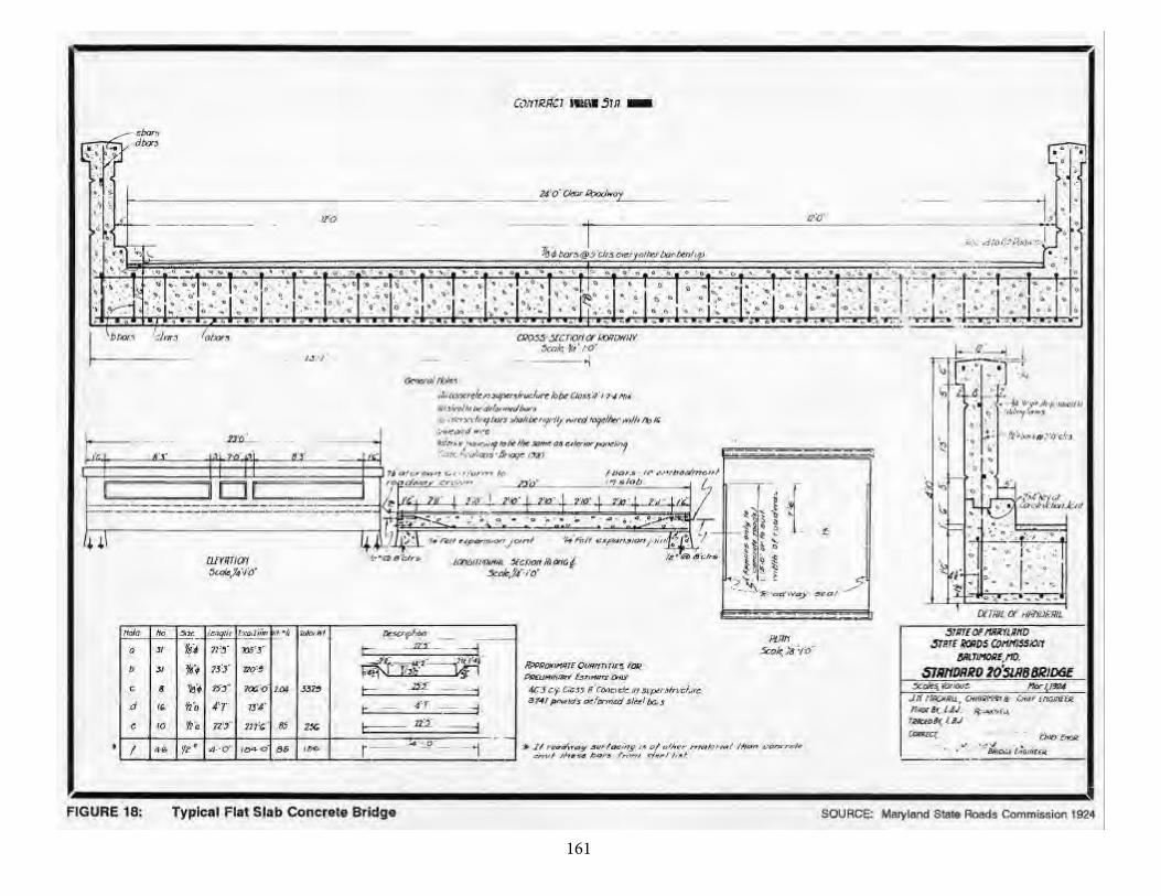
161146
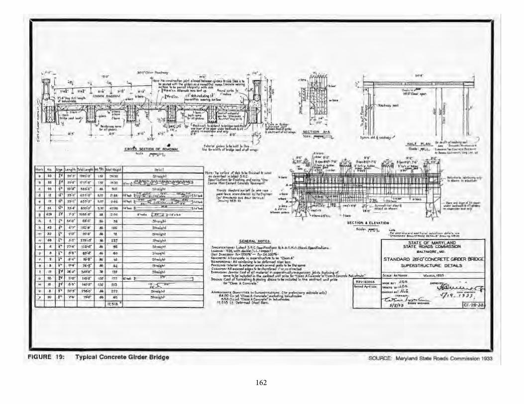
162147

163
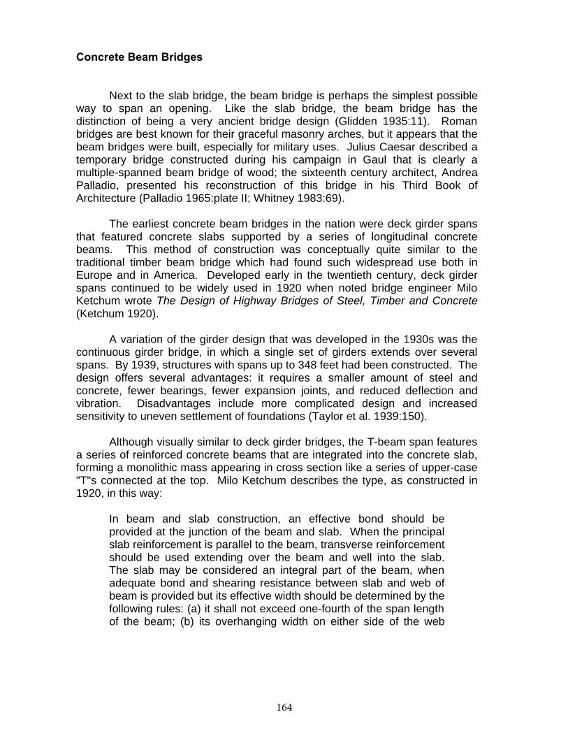
164
148
Concrete Beam Bridges
Next to the slab bridge, the beam bridge is perhaps the simplest possibleway to span an opening. Like the slab bridge, the beam bridge has thedistinction of being a very ancient bridge design (Glidden 1935:11). Romanbridges are best known for their graceful masonry arches, but it appears that the beam bridges were built, especially for military uses. Julius Caesar described atemporary bridge constructed during his campaign in Gaul that is clearly amultiple-spanned beam bridge of wood; the sixteenth century architect, AndreaPalladio, presented his reconstruction of this bridge in his Third Book ofArchitecture (Palladio 1965:plate II; Whitney 1983:69).
The earliest concrete beam bridges in the nation were deck girder spansthat featured concrete slabs supported by a series of longitudinal concretebeams. This method of construction was conceptually quite similar to thetraditional timber beam bridge which had found such widespread use both inEurope and in America. Developed early in the twentieth century, deck girderspans continued to be widely used in 1920 when noted bridge engineer MiloKetchum wrote The Design of Highway Bridges of Steel, Timber and Concrete(Ketchum 1920).
A variation of the girder design that was developed in the 1930s was thecontinuous girder bridge, in which a single set of girders extends over severalspans. By 1939, structures with spans up to 348 feet had been constructed. The design offers several advantages: it requires a smaller amount of steel andconcrete, fewer bearings, fewer expansion joints, and reduced deflection andvibration. Disadvantages include more complicated design and increasedsensitivity to uneven settlement of foundations (Taylor et al. 1939:150).
Although visually similar to deck girder bridges, the T-beam span features a series of reinforced concrete beams that are integrated into the concrete slab,forming a monolithic mass appearing in cross section like a series of upper-case"T"s connected at the top. Milo Ketchum describes the type, as constructed in1920, in this way:
In beam and slab construction, an effective bond should beprovided at the junction of the beam and slab. When the principalslab reinforcement is parallel to the beam, transverse reinforcement should be used extending over the beam and well into the slab.The slab may be considered an integral part of the beam, whenadequate bond and shearing resistance between slab and web ofbeam is provided but its effective width should be determined by the following rules: (a) it shall not exceed one-fourth of the span length of the beam; (b) its overhanging width on either side of the web
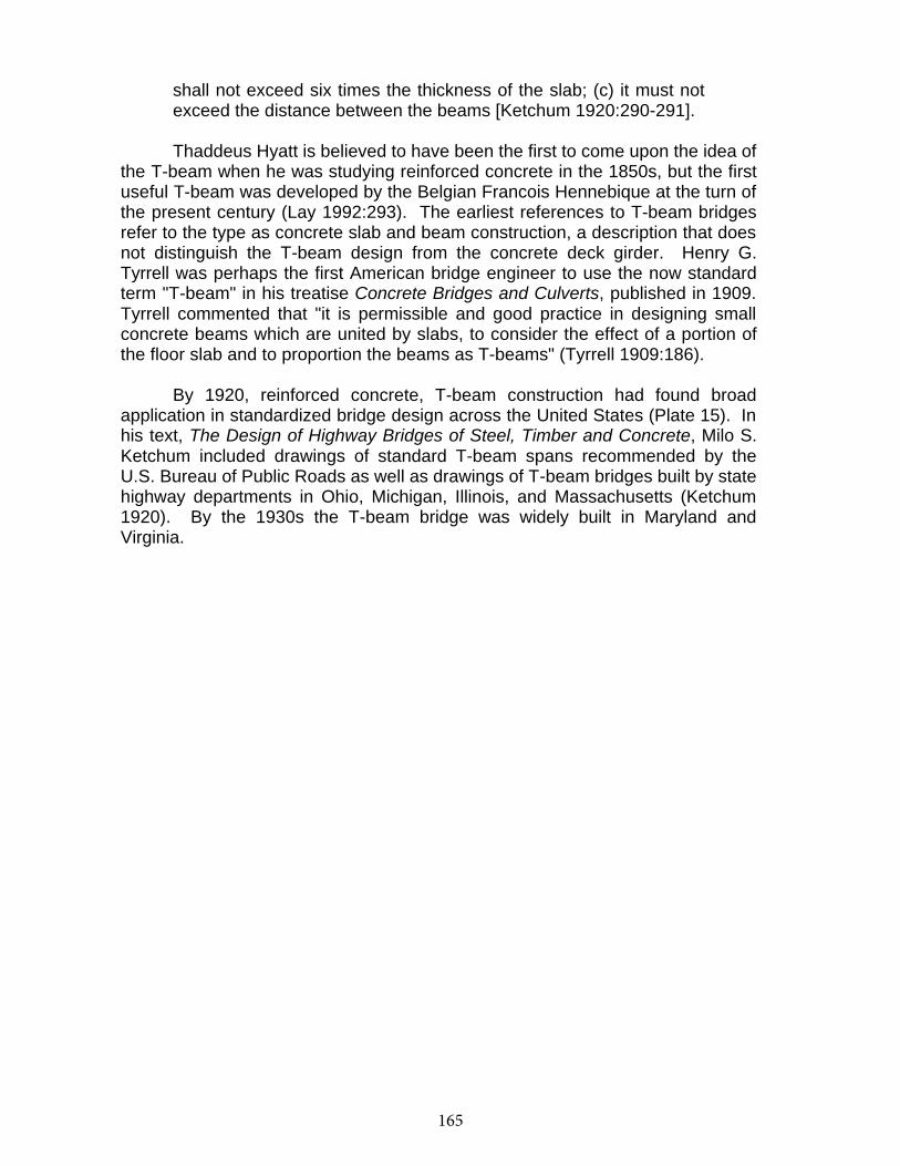
165
149
shall not exceed six times the thickness of the slab; (c) it must notexceed the distance between the beams [Ketchum 1920:290-291].
Thaddeus Hyatt is believed to have been the first to come upon the idea of the T-beam when he was studying reinforced concrete in the 1850s, but the firstuseful T-beam was developed by the Belgian Francois Hennebique at the turn of the present century (Lay 1992:293). The earliest references to T-beam bridgesrefer to the type as concrete slab and beam construction, a description that does not distinguish the T-beam design from the concrete deck girder. Henry G.Tyrrell was perhaps the first American bridge engineer to use the now standardterm "T-beam" in his treatise Concrete Bridges and Culverts, published in 1909.Tyrrell commented that "it is permissible and good practice in designing smallconcrete beams which are united by slabs, to consider the effect of a portion ofthe floor slab and to proportion the beams as T-beams" (Tyrrell 1909:186).
By 1920, reinforced concrete, T-beam construction had found broadapplication in standardized bridge design across the United States (Plate 15). In his text, The Design of Highway Bridges of Steel, Timber and Concrete, Milo S.Ketchum included drawings of standard T-beam spans recommended by theU.S. Bureau of Public Roads as well as drawings of T-beam bridges built by state highway departments in Ohio, Michigan, Illinois, and Massachusetts (Ketchum1920). By the 1930s the T-beam bridge was widely built in Maryland andVirginia.
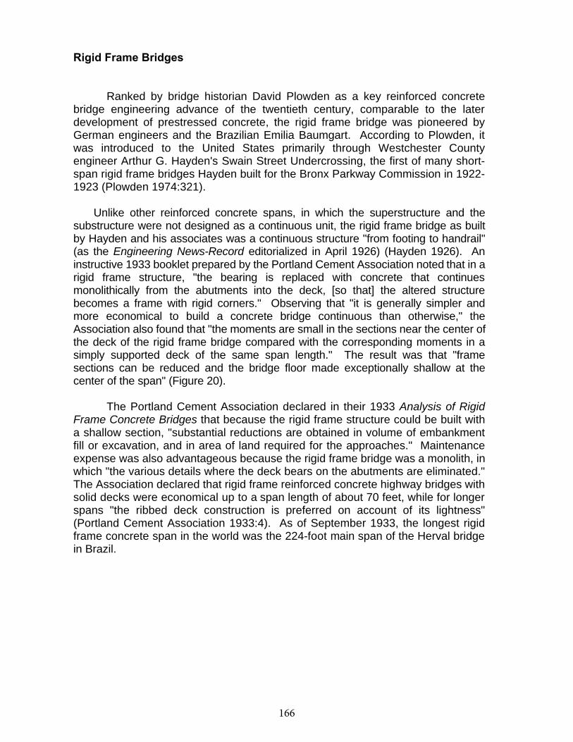
166
149
Rigid Frame Bridges
Ranked by bridge historian David Plowden as a key reinforced concretebridge engineering advance of the twentieth century, comparable to the laterdevelopment of prestressed concrete, the rigid frame bridge was pioneered byGerman engineers and the Brazilian Emilia Baumgart. According to Plowden, itwas introduced to the United States primarily through Westchester Countyengineer Arthur G. Hayden's Swain Street Undercrossing, the first of many short-span rigid frame bridges Hayden built for the Bronx Parkway Commission in 1922-1923 (Plowden 1974:321).
Unlike other reinforced concrete spans, in which the superstructure and thesubstructure were not designed as a continuous unit, the rigid frame bridge as builtby Hayden and his associates was a continuous structure "from footing to handrail"(as the Engineering News-Record editorialized in April 1926) (Hayden 1926). Aninstructive 1933 booklet prepared by the Portland Cement Association noted that in a rigid frame structure, "the bearing is replaced with concrete that continuesmonolithically from the abutments into the deck, [so that] the altered structurebecomes a frame with rigid corners." Observing that "it is generally simpler andmore economical to build a concrete bridge continuous than otherwise," theAssociation also found that "the moments are small in the sections near the center of the deck of the rigid frame bridge compared with the corresponding moments in asimply supported deck of the same span length." The result was that "framesections can be reduced and the bridge floor made exceptionally shallow at thecenter of the span" (Figure 20).
The Portland Cement Association declared in their 1933 Analysis of RigidFrame Concrete Bridges that because the rigid frame structure could be built witha shallow section, "substantial reductions are obtained in volume of embankmentfill or excavation, and in area of land required for the approaches." Maintenanceexpense was also advantageous because the rigid frame bridge was a monolith, in which "the various details where the deck bears on the abutments are eliminated."The Association declared that rigid frame reinforced concrete highway bridges with solid decks were economical up to a span length of about 70 feet, while for longer spans "the ribbed deck construction is preferred on account of its lightness"(Portland Cement Association 1933:4). As of September 1933, the longest rigidframe concrete span in the world was the 224-foot main span of the Herval bridge in Brazil.
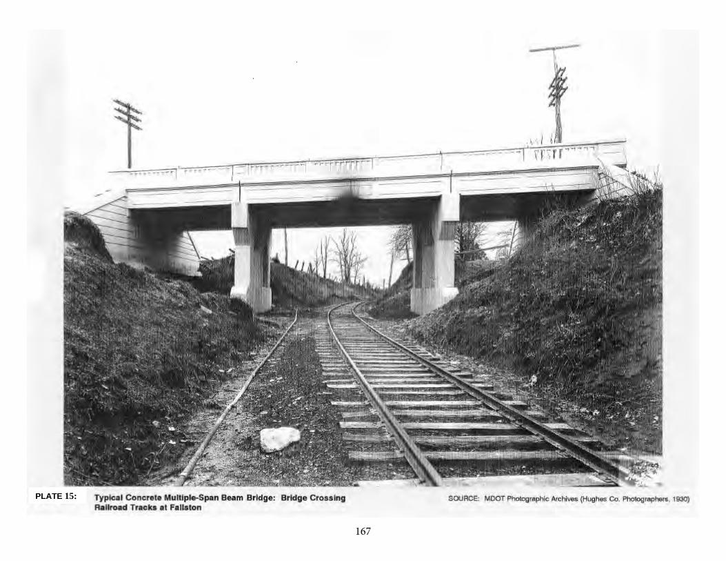
167150
PLATE 15:
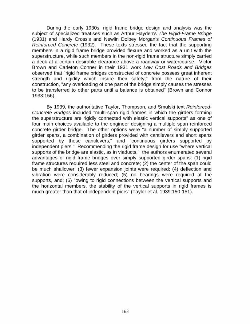
168
151
During the early 1930s, rigid frame bridge design and analysis was thesubject of specialized treatises such as Arthur Hayden's The Rigid-Frame Bridge(1931) and Hardy Cross's and Newlin Dolbey Morgan's Continuous Frames ofReinforced Concrete (1932). These texts stressed the fact that the supportingmembers in a rigid frame bridge provided flexure and worked as a unit with thesuperstructure, while such members in the non-rigid frame structure simply carried a deck at a certain desirable clearance above a roadway or watercourse. VictorBrown and Carleton Conner in their 1931 work Low Cost Roads and Bridgesobserved that "rigid frame bridges constructed of concrete possess great inherentstrength and rigidity which insure their safety;" from the nature of theirconstruction, "any overloading of one part of the bridge simply causes the stresses to be transferred to other parts until a balance is obtained" (Brown and Connor1933:156).
By 1939, the authoritative Taylor, Thompson, and Smulski text Reinforced-Concrete Bridges included "multi-span rigid frames in which the girders formingthe superstructure are rigidly connected with elastic vertical supports" as one offour main choices available to the engineer designing a multiple span reinforcedconcrete girder bridge. The other options were "a number of simply supportedgirder spans, a combination of girders provided with cantilevers and short spanssupported by these cantilevers," and "continuous girders supported byindependent piers." Recommending the rigid frame design for use "where vertical supports of the bridge are elastic, as in viaducts," the authors enumerated several advantages of rigid frame bridges over simply supported girder spans: (1) rigidframe structures required less steel and concrete; (2) the center of the span could be much shallower; (3) fewer expansion joints were required; (4) deflection andvibration were considerably reduced; (5) no bearings were required at thesupports, and; (6) "owing to rigid connections between the vertical supports andthe horizontal members, the stability of the vertical supports in rigid frames ismuch greater than that of independent piers" (Taylor et al. 1939:150-151).
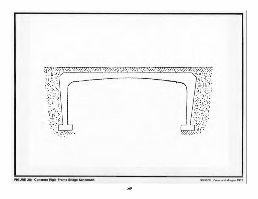
169152

170
153
Taylor et al. also noted certain disadvantages of rigid frame bridges,including the following: (1) rigid frames were suitable only at sites whereunyielding foundations could be ensured, for uneven settlement produced a "bad effect" on their strength; (2) placing of steel reinforcement in the concreterequired considerable skill; (3) the sequence of concrete placement and removal of formwork was sometimes more complicated; and (4) design of rigid framebridges was somewhat more complex because such structures were "staticallyindeterminate," and analysis was not as straightforward as in the case ofstatically determinate, simply supported spans. In the hands of a competentengineer, the authors asserted, these disadvantages disappeared (Taylor et al.1939:150-151).
171
153
Culverts
Technologically the culvert has been defined as "a small bridge constructed entirely below the elevation of the roadway surface and having no part or portionintegral therewith. Structures over 20 feet in span parallel to the roadway areusually called bridges, rather than culverts; and structures less than 20 feet inspan are called culverts even though they support traffic loads directly" (U.S.Department of Transportation 1979:G-13). As distinct from a highway bridge, aculvert is "a conduit constructed through embankments for the purpose ofconducting small streams or surface water" (Hool and Kinne 1924:579). In 1924,culverts with span length of 25 to 30 feet or more were considered bridges; by1979, spans of 20 feet or more were generally deemed bridges (Hool and Kinne1924:579; U.S. Department of Transportation 1979:G-13). Culverts may besingle-span or multiple-span structures (Figure 21).
Disregarding pipe culverts, concrete culverts can be divided into box andarch culverts. Box culverts have square or rectangular openings; arch culvertsfeature either a Roman or a semicircular arch. Culverts often feature a floor, butmany were built without one. Given the ubiquitousness of culverts, it is notsurprising that standardization was applied to their design at an early date;Ketchum's 1920 text provides examples of standard designs from the U.S. Bureau of Public Roads as well as the state highway departments of Iowa and Michigan.Also presented is an 8-foot design for the highways of Puerto Rico by EdwinThacher (Ketchum1920).
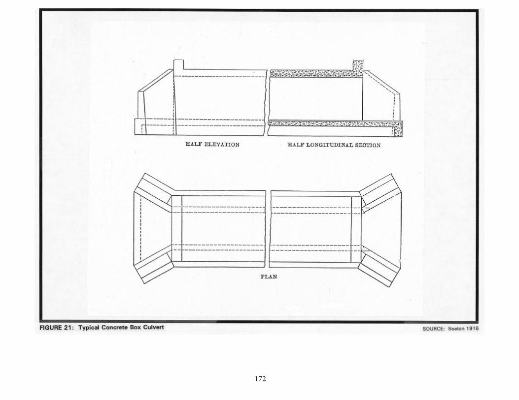
172154
173
155
CONCRETE BRIDGES IN MARYLAND
The Advent of Concrete Bridges in Maryland
The first mention of the use of concrete occurs in the Maryland Geological Survey's Report on the Highways of Maryland, published in 1899. In his chapter, "The Present Condition of Maryland Highways," Arthur Newhall Johnson noted that "iron bridges are. . .fast replacing the longer wooden spans." Observing that comparatively few I-beam bridges, "one of the cheapest and best forms for spans less than 25 or 30 feet," had been built in Maryland, Johnson recommended a transitional form of reinforced concrete construction, stating "no method of construction is more durable than the combination of masonry and I-beams, between which are transverse arches of brick, the whole covered with concrete, over which is laid the roadway" (Johnson 1899:206). Hired in 1898 as the first Highway Engineer of the Maryland Geological Survey Commission, Johnson had previously been a member of the Board of Highway Commissioners of Massachusetts (Maryland State Roads Commission 1964:42).
Although the design described by Johnson appears never to have been built in Maryland, another composite design was constructed in Baltimore soon thereafter, in 1902, at Lancaster Street over the Central Avenue Sewer. Built under the "system of replacing temporary wooden structures with permanent stone, or iron, started in 1900," the Lancaster Street bridge was originally constructed with "an iron I-beam construction, with a wooden floor." The wood floor was subsequently found to be "a source of perpetual expense, very unsatisfactory, and more or less dangerous." Dissatisfied with this bridge, City engineers converted the bridge into "the most important and novel" of structures by the use of "Ferro-Concrete, or Armored Concrete" construction techniques. As
described in the 1902 Annual Report of the Chief Engineer, the transformation of the bridge occurred in the following fashion:
The iron beams were first well cleaned, then covered with coal tar and surrounded with concrete; the spaces between the beams were filled with a floor of concrete six inches thick, reinforced with six-inch mesh expanded metal: on top of the concrete was placed a coating of coal tar to exclude the moisture, the whole finished with a vitrified brick pavement [Baltimore City Chief Engineer 1903:10].
The use of a metal mesh to reinforce the concrete was the first step in Maryland toward the development of true reinforced concrete construction; the concrete was no longer simply encasing the metal members for protective purposes but also contributed to the bridge's load-bearing capacity. The
174
156
experiment with this type of construction was a success: "the conclusion was reached that such a floor was strong enough to withstand four times the heaviest load that could ever come upon it" (Baltimore City Chief Engineer 1903:10).
The first Maryland concrete bridge to feature reinforcing bars was the bridge at Sherwood Station, built in 1903 by Baltimore County. The announcement of this bridge's completion in the Third Report on the Highways of Maryland reveals the pride that was felt at its construction:
The bridge that was built this year, 1903, near Sherwood Station shows the progressive character of the work that the County Roads Engineer is inaugurating. What is known as the steel concrete form of construction was adopted, which uses reinforced concrete beams instead of simple steel or wooden beams as in other forms of construction; this is the first example of its kind in the State [Johnson 1903:169].
The announcement goes on to report that "steel rods are imbedded in the concrete beams to enable them to withstand heavy loads; but no steel surface is exposed to air, so that there is practically no cost for maintenance of a bridge of this character" (Johnson 1903:169).
It should be pointed out that perhaps one of the reasons for the optimism expressed is that concrete construction relied upon local materials and labor. A great number of Maryland's metal truss bridges had been fabricated by out-of-state bridge companies, a fact that surely did not go unnoticed by local officials and residents. Daniel Luten certainly did not ignore this point when advocating his concrete bridges: "Concrete bridges are built with home labor and materials. The money expended for a concrete bridge returns directly to the taxpayers" (Luten 1917).
Baltimore City quickly followed with a reinforced concrete bridge of its own, at Lexington Street over Gwynn's Run. Although termed a "culvert," its 66-foot span certainly qualifies it as a full-scale bridge. The structure was "the first reinforced concrete arch which has been built by the city" (Annual Report of the City Engineer 1905:92) and may be the first reinforced concrete arch in the state. According to the report, "Kahn" bars were used to reinforce the concrete. However, this was not the first time that Baltimore City had built a concrete arch; a concrete arch, in an unreinforced form, was used in 1900 to lead the Schroeder's Run sewer as an open drain underneath residences (Annual Report of the City Engineer 1901:7).
The success of reinforced bridges at Sherwood Station and in Baltimore City quickly led to the adoption by the Maryland Geological Survey of a plan for reinforced concrete bridge construction, as described by Walter Wilson Crosby, Chief Engineer: "The general plan has been to replace these [wood bridges] with
175
157
pipe culverts or concrete bridges and thus forever do way with the further expense of the maintenance of expensive and dangerous wooden structures" (Crosby 1908:379). The first noteworthy step in this plan appears to have been the construction in 1906 of a 200-foot-long, multiple-span, reinforced concrete deck girder bridge over the Choptank River (Crosby 1908:73).
Washington County, the location of many early nineteenth century stone arch bridges, built a number of arches during this early period. Maryland Historical Trust survey forms indicate that in 1906 the Nelson Construction Company of Chambersburg and Pittsburgh, Pennsylvania, built a reinforced concrete single-arch bridge for the Washington County Commissioners (MHT WA-II-128). Apparently the County Commissioners were pleased with the results; the same company (occasionally appearing as Nelson Merydith Company) built bridges of the same design for the county in 1907 (MHT WA-V-063), 1908 (MHT WA-I-344), and 1909 (MHT WA-II-176).
After the success of its first reinforced concrete bridge in 1904, Baltimore City appears to have made a commitment to the arch design. In 1908 construction of three reinforced concrete arch bridges was begun, at Hollins Street over Gwynns Run, University Parkway over Stony Run, and Edmondson Avenue over Gwynns Falls (Annual Report of the City Engineer 1909:12-14). The plans for the Edmondson Avenue bridge were prepared by W.J. Douglas, a bridge engineer from the District of Columbia. The Baltimore Ferro-Concrete Company constructed the multiple-span, 540-foot-long bridge between 1908 and 1910.
In the Third Report on State Highway Construction (1908-1910), Chief Engineer Crosby noted the construction of two double-span arch bridges built by the Luten Bridge Company, both spanning Rock Creek in Montgomery County (Crosby 1910:48). These appear to have been the first arch bridges constructed by the noted bridge company in Maryland, although only a thorough survey can confirm or deny this assessment. Luten built a number of arch bridges throughout Maryland in the following decade, including a single-span arch over Gwynns Falls at Liberty Road in 1913 (Maryland State Roads Commission 1916:67) and a four-span bridge over the Anacostia River in 1914. Built for the State Roads Commission for $11,619, the Anacostia River bridge was 199 feet long and featured a 22-foot-wide roadway. In 1919 Luten built the still-extant Sandy Island Bridge over the Choptank River at Goldsboro for the Caroline County Commissioners (MHT CAR-257). This bridge, consisting of four closed spandrel arches with a classical balustrade, is a fine illustration of the refined architectural aesthetic that Luten's "Park Bridge of Attractive Design" made possible.
176
158
The Development of Standard Plans
There are indications that standard plans for Maryland bridges were drawn up in 1909, but the first clear issue of such plans occurred in 1912, concurrent with the reorganization of the State Roads Commission, which involved the consolidation of the construction and maintenance departments and the establishment of eight districts with their own Resident Engineers (Maryland State Roads Commission 1916:57). The decentralization of the Commission "saved the State thousands of dollars yearly in expenses" and resulted in increased effectiveness, a result experienced by other states which took the same approach.
Although decentralization had its advantages, there was the danger that "the right hand wouldn't know what the left hand was doing" as the Commission embarked upon the formidable task of improving the roads and bridges of Maryland. In addition to highway resurfacing, road improvement entailed the replacement of large numbers of bridges that were inadequate to the vehicular needs of the state. If Resident Engineers were to replace all of these bridges with individually designed spans, they would not be able to keep up with the amount of work that needed to be done. Reinforced concrete construction had been successfully used to build safe bridges with reduced labor costs and, it was hoped, reduced maintenance costs, but the labor involved in individually designing all bridges would have been prohibitive. A method of reducing design time was critically needed.
The introduction of standard plans allowed the Resident Engineer to find a quick and effective solution to the problem. Although standard plans were not applicable to all bridge sites, for reasons of engineering or aesthetics, they could be used in a great number of cases.
The creation of standard plans and a description of their use was first announced in the 1912-1915 Reports of the State Roads Commission:
Standard plans have been made for all bridges of spans up to 36 feet in length and it is only necessary for the Resident Engineer to investigate the foundations, then refer to the standard plan and select the type of foundation that will fit the location and conditions and take off the length of spans. The water shed is carefully figured up by the Resident Engineer when he makes his preliminary inspection and it is afterwards
checked by the Engineer of Surveys. On old roads all openings of the old bridges and culverts are carefully noted, the high-water mark established and the storm areas computed. On spans exceeding 36 feet separate designs are worked up for each individual case [Maryland State Roads Commission 1916:57].
177
159
Published on a single sheet, the 1912 Standard Plans included those structures that were amenable to such an approach: slab spans, (deck) girder spans, box culverts, box bridges, abutments, and piers (Maryland State Roads Commission 1912b). Slab spans, with lengths of 6 to 16 feet in two-foot increments, featured a solid parapet railing that was integrated into the slab. (Deck) girder spans, with lengths of 18 to 42 feet in irregular increments, also featured an integrated solid parapet railing. It is interesting to note that the Standard Plan features a 42-foot span, apparently contradicting the above statement that individual plans were drawn up for spans exceeding 36 feet. The roadway for all spans was a uniform 22 feet, which exceeded by 8 feet the then current 14-foot-wide standard section for concrete road construction (Maryland State Roads Commission 1930b:85).
In the Report for the years 1916-1919, a revision of the standard plans was noted:
During the four years covered by this report, it has been found necessary to revise our standard plans for culverts and bridges, to take care of the increased tonnage which they have been forced to carry. Army cantonments. . .increased their operations several hundred per cent, and the brunt of the enormous truck traffic resulting therefrom, was borne by the State Roads of Maryland. In addition to these war activities, freight motor lines from Baltimore to Washington, Philadelphia, New York, and various points throughout Maryland, and the weight of many of these trucks when loaded, was in excess of the loads for which our early bridges were designed [Maryland State Roads Commission 1920b:56].
Published on separate sheets, the new standard plans (Maryland State Roads Commission 1919) for slab bridges reveal that the major changes were an increase in roadway width from 22 feet to 24 feet and a redesign of the reinforcements. The diameter of the reinforcing bars was reduced in the 1919 slab span design (on a 10-foot span from 3/4 inch to 5/8 inch) and the space between bars was reduced (5 inches to 4½ inches), thereby increasing the number of reinforcing bars but decreasing their individual size and weight. The slab spans continued to feature solid parapets integrated into the span. The range of span lengths remained 6 to 16 feet, but the next year (1920) witnessed the issue of a supplemental plan for a 20-foot-long slab span (Maryland State Roads Commission 1920b); presumably there was also a plan for an 18-foot-long span, but this has not been located.
It should also be noted that among the 1919 standard plans for reinforced concrete structures was a design for a movable bridge operator's house. It was during this period in Maryland that reinforced concrete was gaining ascendancy
178
160
over timber and steel as the material of choice for constructing the stationary approach spans of movable bridges.
The Report for 1920-1923 states that "new standard plans have been prepared for slab and girder spans and the type of the latter has been changed from the beam to the T-beam design, with a resulting saving in material" (Maryland State Roads Commission 1924b:58). Thus, by 1923 the State Roads Commission had decided to adopt the T-beam design which had been described by Tyrrell in 1909 (Tyrrell 1909:186), advocated by the U.S. Bureau of Roads in the teens, and already adopted by several states by 1920.
The 1924 standard plan for the T-beam spans contained a note which characterizes the new mode of construction: "No construction joint allowed between girders and slab. Girders with slab to be poured as a monolithic mass." Among the changes included in the 1924 standards for T-beams were a reduced beam section; span designs in lengths of regular two-foot increments; and a reduced range of span lengths which incorporated designs from 22 feet to 40 feet.
The 1924 standard plans remained in effect until 1930, when the roadway width for all standard plan bridges was increased to 27 feet in order to accommodate the increasing demands of automobile and truck traffic (Maryland State Roads Commission 1930b). The range of span lengths remained the same, but there were some changes designed to increase load bearing capacities. The reinforcing bars were increased in thickness for both slab and T-beams and the cross section of the T-beam bottom flange became more robust (for the 22-foot-long span, thickness was increased by 3 inches and height by 4.5 inches). Visually, the 1930 design can be distinguished from its predecessors by the pierced concrete railing that was introduced at this time.
Three years later, in 1933, a new set of standard plans was introduced (Maryland State Roads Commission 1933). This time, their preparation was not announced in the Report; new standard plans were by this time unremarkable. Once again accommodating the ever-increasing demands of traffic, the roadway width was increased, this time to 30 feet. The slab span's reinforcing bars remained the same diameter but were placed closer together to achieve still more load bearing capacity. In order to accomplish the same goal for the T-beam span, the number of beams was increased from five to six, the first such change since the introduction of girder spans in 1912. The increase in the number of beams allowed a decrease in section size for girders which made them equivalent to the 1924 T-beam section.
A system of standard nomenclature for plans was introduced at this time: span type was indicated by a two-letter designator followed by span length and the year of the plan. Thus, CS-18-33 indicates an 18-foot concrete slab of the 1933 standard plan design; CG-36-33 was a 36-foot concrete girder (T-beam) of
179
161
the same year. The inclusion of the year designator gave ready access to design details for each bridge and indicates that the State Roads Commission anticipated revisions to standard plans.
Concrete Arch, Beam, Slab, and Rigid Frame Bridges in Maryland
In Maryland, as in the rest of the nation, the standardized concrete types became the predominant bridge types built. An examination of data on the extant concrete bridges on Maryland state roads (State Highway Administration 1993) indicates the growth of the standardized beam and slab bridge at the expense of the arch; but further research and field survey will be needed to substantiate this conclusion. In the period 1911 to 1920 (the decade in which standardized plans were introduced), beams and slabs constituted 65 percent and arches 35 percent of the extant 29 bridges built. In the following decade, 1921-1930, the beam (now the T-beam) and slab increased to 73 percent and the arch had declined to 27 percent of the 129 extant bridges; in the next decade (1931-1940) the beam and slab achieved 82 percent and arches had further declined, constituting only 18 percent of the total of extant bridges built between 1931 and 1946 on state-owned roads.
Although beam and slab bridges became the utilitarian choice, it appears that the arch was selected when aesthetic as well as other site conditions were considered. The architectural treatment of extant arch bridges supports this assessment. Baltimore's Clifton Avenue Bridge, built in 1927, features an open spandrel arch and refined architectural detailing. The Route 195 bridge over Sligo Creek (MHT M:37-7) is another example of the architectural distinction achieved by arch bridges. Built in 1932, the bridge features three open spandrel arches. In Washington County, the Route 40 bridge over the Conococheague Creek (HAER No. MD-41-17) is notable for its grace; built in 1936, it features three open spandrel arches, the spandrel openings capped by arches that complement the profile of the arch ribs. A known four-span Luten arch of the "Park Bridge of Attractive Design" was built in 1919 to carry Maryland Route 287 over the Choptank River near Goldsboro (MHT CAR-257).
Maryland state bridge inventories indicate that there are nearly 70 extant arch bridges on state highways that were constructed in the 1900-1940 period, as well as an equivalent number from the same period that are located on county or municipal roads. For the vast majority of these bridges, neither the specific form of arch (i.e., barrel, closed spandrel, or open spandrel) nor the degree of architectural detailing is known from the information available. Likewise, although it can be safely assumed that the majority of the 90 beam and 122 slab bridges built between 1900 and 1940 rigorously conform to standard plans, there may be early examples that precede standardization as well as later, individually designed and more architectural versions of these types.
180
162
Maryland's early twentieth century bridges also include at least 11 structures representative of the rigid frame bridge type, as developed during the 1930s and early 1940s in the United States. Although historical research has uncovered little more than brief references to these bridges (references primarily drawn from the 1993 Maryland Department of Transportation Inventory of Bridges), they constitute examples of a category of modern concrete bridge that has been recognized as technologically significant by historians and industrial archaeologists.
The State Highway Administration's current list of county-owned and municipal bridges references a structure that may be the earliest known example of a rigid frame bridge in Maryland. This is the bridge in Worcester County carrying Big Mill Road over Big Mill Pond, and briefly listed as a "concrete rigid frame" built in 1919 but reconstructed or rebuilt in 1930 (Maryland Department of Transportation 1993b). This may be an early example, as Westchester Parkway engineer Arthur Hayden did not pioneer small-span rigid frame bridge design until 1922-1923. The Big Mill Road Bridge warrants further investigation to determine its exact nature.
The earliest extant rigid frame bridge listed on the 1993 statewide inventory of bridges is Bridge 6031, consisting of two 35-foot spans carrying State Route 97 over Big Pipe Creek in Carroll County. The longest Maryland rigid frame structure located through historical research is Bridge 11018, a 120-foot, two-span rigid frame bridge built in 1937 to carry State Route 135 over the Savage River in Garrett County. Five out of the total of 11 rigid frame bridges constructed between 1934 and 1941 were built in connection with a major project of the Maryland State Roads Commission, the upgrading and widening of U.S. Route 40 from the Maryland-Delaware line to western Maryland.
Of these five structures, three are located in Washington County (two built in 1936 and one in 1941), and one each in Harford and Howard counties (built in 1938 and 1939, respectively). One of the five Route 40 rigid frame bridges, Bridge 12027 crossing a branch of Winters Run in Harford County, consisted of five 10-foot-long spans.
181
162
Conclusion
The following summary statements regarding structural characteristics forconcrete bridges, key periods of significance for concrete bridges in Maryland,and the earliest known documented examples of concrete bridges in the stateare based solely on documentary research.
Concrete bridges (see Figures 18 through 21) comprise a number ofstructural variants, including arches, girders, slabs, and rigid frames. Most extant concrete bridges are built of reinforced concrete, or concrete reinforced withmetal components such as metal shapes, girders, beams, or reinforcing bars.Concrete bridges may be categorized by the configuration and arrangement oftheir major components. Substructure and superstructure are usuallyconstructed of concrete, including parapet walls or railings.
Concrete arch bridges (see Plates 13 and 14) include closed spandrel and open spandrel variants, spanning between concrete abutments (the spandrel isthe area of the arch between the ring and the roadway). The closed spandrelconcrete arch bridge consists of an arch barrel, on the outermost edges of which are built spandrel walls which serve as retaining walls to contain the fill material(rubble, stones, or dry soil) deposited over the arch. The spandrel walls of aclosed spandrel concrete arch may extend above the roadway deck level to form the parapet walls of the bridge. When viewed in elevation, the open spandrelarch is pierced above the arch ring. The arch ring of an open spandrel concrete arch bridge may be a barrel or it may be further divided into parallel arch ribs.The open spandrel variant of concrete arch does not contain fill material between the spandrel walls; deck loads are carried by cross walls or spandrel columnssupported by the concrete arch ring. A special variant of concrete arch bridge isthe through arch, or "Rainbow" arch, characterized by a concrete arch extendingabove the level of the roadway deck and supporting the deck by means ofconcrete posts, or suspenders.
Concrete slab bridges (see Figure 18) consist of a concrete slab spanning between concrete abutments and wingwalls, and flanked by concrete parapets.The slab bridge is typically constructed entirely of reinforced concrete, withminimally ornamented parapet walls.
Concrete beam, or girder, bridges (see Figure 19 and Plate 15) consist of a concrete deck, supported on concrete beams (I-beams or T-beams, in crosssection), spanning between concrete abutments and wingwalls, and flanked byconcrete parapets. In certain concrete beam bridges, the concrete parapet is astructural, reinforced concrete component acting with the beams to support thedeck loads; sometimes the parapet walls are treated with linear ornamentation.
182
163
Concrete rigid frame bridges (see Figure 20) are structures in which thereinforced concrete continues monolithically from the abutments into thesuperstructure, thus eliminating the bearings characteristic of slab and beambridges. The monolithic concrete construction of the rigid frame bridge makes ita bridge with four rigid joints. In multiple-span rigid frame concrete bridges orviaducts, the girders forming the superstructure may also be rigidly connectedwith intermediate vertical supports or concrete piers.
As indicated by documentary research, key periods of significance forconcrete bridges in Maryland include 1890-1910, the era in which reinforcedconcrete bridge construction was introduced and popularized within the state, byBaltimore City and Baltimore County officials as well as state highway engineers in the Maryland Geological Survey and State Roads Commission; 1910-1940,when reinforced concrete bridge building in the state was characterized by theincreasing standardization of small slab, beam, frame and culvert spans, and the introduction of special subtypes of reinforced concrete bridges such as the Luten arch (in various patented designs), the open spandrel ribbed arch, the rigid frame bridge and concrete girder bridges built as grade crossing elimination structures; and 1940-present, when reinforced concrete prestressing, to increase the load-bearing capacity of bridges, was introduced in the state for highway bridge use.
The earliest reinforced concrete bridges built in Maryland were theLancaster Street Bridge built in 1902 by Baltimore City (featuring a reinforcedconcrete deck), and the Sherwood Station Bridge built in 1903 by BaltimoreCounty (including reinforced concrete beams). Early concrete arch bridges inMaryland included the bridge carrying Lexington Street over Gywnn's Run (1904) and a group of reinforced concrete arch spans built between 1906 and 1909 inWashington County by the Nelson Construction Company. An early, multiple-span reinforced concrete deck girder bridge was built by state highway engineers in 1906 to cross the Choptank River. The earliest known reinforced concretearch bridges built by Daniel Luten's National Bridge Company in Maryland weretwo double-span arch bridges built between 1908 and 1909 to span Rock Creekin Montgomery County. Field survey and further research will be necessary todetermine the earliest open spandrel ribbed arch and the first reinforced concrete rigid frame bridges built in Maryland. As few concrete or reinforced concretebridges have been previously surveyed or studied in Maryland, field survey andadditional research will also be required to identify significant extant concretebridges located in the state.
183165
SECTION X: BIBLIOGRAPHY
Alison, Gordon A. 1984 Evaluation of Seven Aluminum Highway Bridges After Two to Three
Decades of Services. Paper presented April 30, 1984, to Aluminum Association of America.
Allen, Bob 1991 U.S. Route 40 in Maryland. Maryland 24:38-43.
Allen, T., and Donald Jackson (compilers) 1975 Bridge Truss Types: A Guide to Dating and Identifying. American
Association for State and Local History, Nashville, Tennessee.
American Association of State Highway Officials 1953a Public Roads of the Past: Historic American Highways. American
Association of State Highway Officials, Washington, D.C.
1953b Standard Specifications for Highway Bridges. American Association of State Highway Officials, Washington, D.C.
American Society of Civil Engineers 1976 American Wooden Bridges. American Society of Civil Engineers, New
York.
American Society of Civil Engineers, Special Committee on Specifications for Bridge Design and Construction 1924 Final Report on Specifications for Design and Construction of Steel
Highway Bridge Superstructure. American Society of Civil Engineers Proceedings 50:266-289.
American Society of Civil Engineers, Task Force on Status-of-the-Art: Wood, ASCE Structural Division 1975 Wood Structures: A Design Guide and Commentary. American Society of
Civil Engineers, New York.
Armstrong, Ellis L. (editor) 1976 History of Public Works in the United States, 1776-1976. American Public
Works Association, Chicago.
Army To Be Allowed Free Crossing of Toll Spans 1941 Baltimore Sun, August 2, 1941.
184
166
Asks 3 Million to Repair State Roads Bridges 1936 Baltimore Sun, March 24, 1936.
Baltimore City Chief Engineer 1900-15 Annual Report of the Chief Engineer. Baltimore.
Baltimore City Commissioner 1856-99 Annual Report of the City Commissioner. Baltimore.
Baltimore City Department of Public Works 1925-49 Annual Report of the Department of Public Works. Baltimore.
Baltimore City Highways Engineer 1917-24 Annual Report of the Highways Engineer. Baltimore.
Baltimore City, Jones' Falls Commission 1882 Report of the Jones' Falls Commission. Baltimore.
Baltimore County Roads Engineer 1908-29 Annual Report of the Baltimore County Roads Engineer. Towson,
Maryland.
Barnett, Charles G. 1971 The Bridges of Laurel. Laurel News Leader, July 15, 1971.
Bearfoot, Paula S. 1983 John Edwin Greiner - The Making of a Gentleman Engineer. Baltimore
Engineer, May 1983:4-7.
Beirne, Francis F. (editor) 1968 Baltimore. . .a Picture History (with a Prologue). Bodine & Associates, Inc.,
Baltimore.
Bid Received To Repair Old Arch Bridge - Casselman River Bridge 1955 Baltimore News-American, October 7, 1954.
Bollman, Wendel 1852 Iron Suspension and Trussed Bridge, As Constructed for the Baltimore &
Ohio Rail Road Company at Harper's Ferry and on the Washington Branch of This Road. John Murphy & Co., Baltimore.
Bowden, Mark 1976 There's Troubled Waters Ahead for Old Toby's Bridge. Baltimore News
American, April 4, 1976.
185167
Boyd, T.H.S. 1880 The History of Montgomery County, Maryland, from its Earliest Settlement
in 1650 to 1879. Published by author, Clarksburg, Maryland.
Bridge Building Plan Advocated 1936 Baltimore Sun, March 29, 1936.
A Bridge the City Let Rot 1976 Baltimore Sun, July 16, 1976.
Bridge Damaged By Fire Will Be Reconstructed 1993 Baltimore Sun, July 24, 1993.
Bridge Fight Goes To Appeals Court 1938 Baltimore Sun, September 10, 1938.
Bridge Program Bill Due To Be Signed 1937 Baltimore Sun, April 13, 1937.
Bridge Scheme Seen As Dead by Roosevelt 1938 Baltimore Sun, September 21, 1938.
Bridge Tolls Exceed Estimates 1942 Baltimore Sun, February 19, 1942.
Bridges to the Past 1968 Baltimore News American, August 8, 1968.
Brooks, Neal A., and Eric G. Rockel 1979 A History of Baltimore County. Friends of the Towson Library, Towson,
Maryland.
Brown, Earl I. 1930 The Chesapeake and Delaware Canal. Papers of the American Society
of Civil Engineers (February).
Brown, Harry M. 1952 The Construction of the Bay Bridge. Baltimore, July 1952:15-17, 40-45.
Brown, Victor J., and Carleton N. Conner 1933 Low Cost Roads and Bridges. Gillette Publishing Company, Chicago.
186
168
Browne, Gary Lawson 1980 Baltimore in the Nation, 1789-1861. University of North Carolina Press,
Chapel Hill, North Carolina.
Browne, William Hand (editor) 1884-1902 Archives of Maryland. . .. Maryland Historical Society, Baltimore.
Brugger, Robert J. 1988 Maryland: A Middle Temperament 1634-1980. The Johns Hopkins
University Press in association with the Maryland Historical Society, Baltimore.
Byron, Chester 1960 Chestertown's Old Wooden Bridge in Its Racetrack Days. Baltimore Sun,
Sunday Magazine, August 14, 1960.
Caemmerer, Paul 1939 A Manual on the Origin and Development of Washington. U.S.
Government Printing Office, Washington, D.C.
Callcott, George H. 1985 Maryland and America, 1940 to 1980. The Johns Hopkins University
Press, New York.
Campaign To Save Bridge Succeeds 1976 Senator Charles Mathias Letter, June 1976.
Cecil County Bridge Predates Civil War 1959 Baltimore Evening Sun, November 2, 1959.
Chard, Jack 1986 Making Iron & Steel: The Historic Processes: 1700-1900. Roebling
Chapter of the Society for Industrial Archaeology, Bogota, New Jersey.
Childs, William F. 1949 Highway Engineering in Maryland [1910-1948]. Surveying and Mapping
9:122-129.
Cilento, Angelo J. n.d. Handstands on a Swingbridge. Unidentified newspaper clipping in
Maryland Historical Society Vertical File, Baltimore.
187169
Clemens, Paul Gilbert Eli 1980 The Atlantic Economy and Colonial Maryland's Eastern Shore: From
Tobacco to Grain. Cornell University Press, Ithaca, New York.
Cochrane, Laura C., and Lavinia R. Crouse 1971 History of Caroline County, Maryland, From Its Beginning. Regional
Publishing Company, Baltimore.
Committee on History and Heritage of American Civil Engineering 1972 A Biographical Dictionary of American Civil Engineers. American Society
of Civil Engineers, New York.
Conowingo To Be Route 1909 Baltimore Sun, February 19, 1909.
Cox, Richard J. 1979 Professionalism and Civil Engineering in Early America: The Vicissitudes
of James Shriver's Career, 1815-1826. Maryland Historical Magazine74:23-38.
Crosby, Walter Wilson 1908 Second Report on State Highway Construction for the Period from
January 1, 1906, to January 1, 1908. Maryland Geological Survey, The Johns Hopkins University Press, Baltimore.
1910 Third Report on State Highway Construction for the Period from January 1, 1908, to January 1, 1910. Maryland Geological Survey, The Johns Hopkins University Press, Baltimore.
Cross, Hardy, and Newlin Dolbey Morgan 1932 Continuous Frames of Reinforced Concrete. John Wiley & Sons, Inc.,
New York.
Cumberland's Old Bridge 1955 Baltimore Sun, September 27, 1955.
Curtis, William T.S. 1899 Cabin John Bridge. Records of the Columbia Historical Society 1899:293-
307.
Darnell, Victor C. 1984 Directory of American Bridge-Building Companies 1840-1900. Occasional
Publication No. 4, Society for Industrial Archeology, Washington, D.C.
188
170
DeLony, Eric 1993 Landmark American Bridges. American Society of Civil Engineers, New
York.
Design and Construction of the Bush and Gunpowder River Bridges, Consisting of a Series of Reinforced Concrete Slab Spans 1914 Engineering and Contracting 50:195-198.
The Destruction of the Railroad Bridge on the Susquehanna 1866 Baltimore American and Commercial Advertiser. Undated clipping.
Deteriorating - Carroll County Bridges 1968 Photographs, Baltimore Sun, February 26, 1968.
Dilts, James D. 1976a Schaefer Grants Cedar Avenue Bridge 1-Week Reprieve. Baltimore Sun,
May 24, 1976.
1976b Zoo Study Held Backing Saving of Cedar Bridge. Baltimore Sun, May 31, 1976.
Duffy, Montgomery and Associates, Consulting Engineers 1980 Historic Structure Report on Jericho Road Covered Bridge over Little
Gunpowder Falls. Report prepared for Baltimore County Planning Department, Towson, Maryland.
Dulaney Bridge Limit Is Cut 1970 Baltimore Sun, August 8, 1970.
Dulaney Valley Bridge 1970 Baltimore News-American, August 23, 1970.
Durrenberger, Joseph Austin 1931 Turnpikes: A Study of the Toll Road Movement in the Middle Atlantic
States and Maryland. Published by author, Valdosta, Georgia.
Ellet, Charles 1854 Report on a Suspension Bridge Across the Potomac for Rail Road and
Common Travel. . . . John C. Clark, Philadelphia.
Emory, Frederic 1950 Queen Anne's County, Maryland: Its Early History and Development, A
series of sketches originally published in the Centreville Observer 1886-1887. The Maryland Historical Society, Baltimore.
189171
Enoch Pratt Free Library 1980 The Eastern Shore of Maryland: An Annotated Bibliography. Queen Anne
Press, Queenstown, Maryland.
Evan, Philip 1961 Picturesque Span Demolished - Crisfield Bridge Goes in Name of
Progress. Baltimore Sun, February 23, 1961.
Fee, Elizabeth, Linda Shopes, and Linda Zeidman 1991 The Baltimore Book: New Views of Local History. Temple University
Press, Philadelphia.
Fielding, Geoffrey W. 1957 The Harbor Tunnel - An Engineering Masterpiece. Baltimore, November
1957:1, 19-21, 23, 41.
First Bridge Over Susquehanna Seen in Resurrected Engraving 1972 Undated clipping in Maryland Historical Society Vertical File, Baltimore.
Reprint of 1867 Scientific American article. The Aegis, Bel Air.
Fitch, George K. 1966 Wendel Bollman. . .and His Times. Baltimore Engineer, November
1966:5-6, 12.
Flemming, Paul 1948 Old Belvedere Bridge. Baltimore Sun, December 12, 1948.
Flood Expected To Result in Enduring Improvements to Bridges and Highways 1936 Baltimore Sun, March 26, 1936.
Form, At Last 1938 Baltimore Sun, August 19, 1938.
Former Covered Bridges of Maryland 1959 Document in Maryland Historical Society Vertical File, Baltimore.
Four-Bridge Act Upheld On Appeal 1938 Baltimore Sun, September 30, 1938.
The Four-Bridge Plan 1938 Baltimore Sun, August 17, 1938.
190172
Gallatin, Albert 1968 Report of the Secretary of the Treasury on the Subject of Public Roads &
Canals. Reprint of 1808 edition. Augustus M. Kelley, New York.
Gibb, Hugh R. 1979 Mendes Cohen: Engineer, Scholar and Railroad Executive. Maryland
Historical Magazine 74:1-10.
Gill, Don 1988 Drive Is On To Save 8 Old Bridges. Baltimore Evening Sun, July 20,
1988.
Glencoe Wins Battle To Get Old-Fashioned Bridge 1976 Baltimore Sun, February 1, 1976.
Glidden, W.R. 1935 Notes on Bridges - Beam Bridges. Virginia Highway Bulletin I(5):11,12.
Goldsborough, Charles 1818 Executive Communication to the General Assembly of Maryland, at
December Session, 1818, on the Subject of Turnpike Roads. . . . Jehu Chandler, Annapolis.
Gould, Clarence P. 1915 Money and Transportation in Maryland, 1720-1765. The Johns Hopkins
University Press, Baltimore.
Gray, Ralph D. 1985 The National Waterway: A History of the Chesapeake and Delaware
Canal, 1769-1985. University of Illinois Press, Urbana and Chicago.
Greene, Suzanne Ellery 1980 Baltimore: An Illustrated History. Sponsored jointly by The Greater
Baltimore Committee, Inc., and The Baltimore City Commission on Historical and Architectural Presentation, Windsor Publications, Inc., Woodland Hills, California.
Grimes, Michael A. 1989 The Development of Baltimore's Northwest Corridor, 1919-1930. Society
for American City and Regional Planning History, Columbus, Ohio.
Gunnarson, Robert 1990 The Story of the Northern Central Railway, From Baltimore to Lake
Ontario. Greenberg Publishing Co., Sykesville, Maryland.
191
173
Guy, Francis 1804 View of the Presbyterian Church and All the Buildings as They Appear
From the Meadow. Painting in collection of Maryland Historical Society, Baltimore.
Hall, Clayton Colman 1967 Narratives of Early Maryland 1633-1684. Reprint of 1910 edition, Barnes
& Noble, Inc., New York.
Hamill, W.S. 1952 The Story of the Bay Bridge. Baltimore 45:18-19, 45-51, 55-64.
1957 The Harbor Tunnel: An Historical Sketch. Baltimore, November 1957:21-23, 41-45, 102-104.
Hardesty, Egbert R., Henry W. Fischer, and Richard W. Christie 1975 Fifty-Year History of Movable Bridge Construction. Journal of the
Construction Division, Proceedings of the American Society of Civil Engineers 101,CO3:511-557.
Harper's Ferry, Place of Many Bridges 1931 Compressed Air Magazine, November 1931:3648.
Harwood, Herbert H., Jr. 1979 Impossible Challenge: The Baltimore and Ohio Railroad in Maryland.
Barnard, Roberts and Company, Baltimore.
Havre Bridge Fund Okayed by President 1938 Baltimore Sun, September 22, 1938.
Hayden, Arthur G. 1926 Rigid Frames in Concrete Bridge Construction. Engineering News-
Record 96(17):686-689.
1931 The Rigid Frame Bridge. McGraw-Hill, New York.
Hayman, John C. 1979 Rails Along the Chesapeake: A History of Railroading on the Delmarva
Peninsula, 1827-1978. Marvadel Publishers [location not given].
Hays, Helen Ashe 1910 The Antietam and Its Bridges. [publisher not given] New York and
London.
192
174
Hiebert, Ray Eldon, and Richard K. MacMaster 1976 A Grateful Remembrance: The Story of Montgomery County, Maryland.
Montgomery County Government and the Montgomery County Historical Society, Rockville, Maryland.
Hilton, G.E. 1913 Historical Sketch of Bridge Development in Baltimore. Monthly Journal of
the Engineers Club of Maryland 2:4, 5.
Hilton, George W. 1976 The MA & PA: A History of the Maryland & Pennsylvania Railroad.
Howell-North Books, San Diego, California.
Historic American Engineering Record 1969-93 File of Maryland recordations, Prints and Photographs Division, Library of
Congress, Washington, D.C.
Historic Bridge Goes Down At Last 1942 Baltimore Sun, March 3, 1942.
Hollifield, William 1978 Difficulties Made Easy: History of the Turnpikes of Baltimore City and
County. Baltimore County Historical Society, Towson, Maryland.
Holmes, William F. 1962 Turnpikes Across the Peninsula. Delaware History 10:71-104.
Hool, George A., and W.S. Kinne (editors) 1924 Reinforced Concrete and Masonry Structures. McGraw-Hill Book
Company, New York.
1943 Movable and Long-Span Steel Bridges. McGraw-Hill Book Company, New York.
Hopkins, G.M. 1877 Atlas of Baltimore County, Maryland. Published by author, Philadelphia.
1878a Atlas of Anne Arundel County, Maryland. Published by author, Philadelphia.
193
175
1878b Atlas of Fifteen Miles Around Washington Including Prince George, Maryland. Published by author, Philadelphia.
1878c Atlas of Howard County, Maryland. Published by author, Philadelphia.
1879 Atlas of Fifteen Miles Around Washington Including County of Montgomery, Maryland. Published by author, Philadelphia.
Horse and Buggy Bridge: The Hammonds Ferry Road Bridge 1954 Photograph, Maryland Gazette, Annapolis, October 7, 1954.
Houghton, A.A. 1912 Concrete Bridges, Culverts and Sewers. The Norman W. Henley
Publishing Company, New York.
Hovey, Otis Ellis 1926 Movable Bridges. John Wiley & Sons, Inc., New York.
Howard, George 1873 The Monumental City: Its Past History and Present Resources. J.D.
Ehlers & Co., Baltimore.
Ickes' Attitude Held Blow to Bridge Hopes 1938 Baltimore Sun, September 17, 1938.
Ierley, Merritt 1990 Traveling the National Road: Across the Centuries on America's First
Highway. The Overlook Press, Woodstock, New York.
It's His Bridge, So You Pay 1969 Baltimore Evening Sun, May 5, 1969.
Jackson, Donald C. 1988 Great American Bridges and Dams. National Trust for Historic
Preservation, The Preservation Press, Washington, D.C.
James, Pamela 1977 The Patterson Viaduct. History Trails 11(3):17, 18.
J.E. Greiner Company 1938 Maryland's Primary Bridge Program. Report prepared for the Maryland
State Roads Commission, Baltimore.
1944 Report Submitted to State Roads Commission of Maryland on Washington-Baltimore Freeway, North form Jessups Road, Including
194176
Highway Approaches to the Patapsco River Bridge and Franklin Street Connection. Baltimore.
1948 The Chesapeake Bay Bridge Engineering Report. Submitted to the Governor, State Roads Commission, State Highway Advisory Council, Baltimore.
1953 Thirteenth Annual Report, Chesapeake Bay Bridge, Susquehanna and Potomac River Bridges. Report prepared for Maryland State Roads Commission, Baltimore.
1954 Civil Engineering Report, Patapsco Tunnel Project. Report prepared for Maryland State Roads Commission, Baltimore.
Jericho Bridge - Going on 113 Years 1978 History Trails 12:9-12.
Johnson, A.E. (editor) 1964 A Story of the Beginning, Purposes, Growth, Activities and Achievements
of AASHO. American Association of State Highway Officials, Washington, D.C.
Johnson, Arthur Newhall 1899 The Present Condition of Maryland Highways. In Report on the Highways
of Maryland. Maryland Geological Survey, The Johns Hopkins University Press, Baltimore.
1903 Third Report on the Highways of Maryland, With Especial Reference to the Operations of the Highway Division During 1902 and 1903. Maryland Geological Survey, The Johns Hopkins University Press, Baltimore.
Jones, Elias 1966 New Revised History of Dorchester County, Maryland. Reprint of 1925
edition. Tidewater Publishers, Cambridge, Maryland.
Joynes, William J. 1963 Covered Bridges. Baltimore American, May 12, 1963.
Jug Bridge 1965 Baltimore News-American, January 10, 1965
Kanarek, Harold 1976 The Mid-Atlantic Engineers: A History of the Baltimore District 1774-1974.
U.S. Army Corps of Engineers, Washington, D.C.
195
177
Kanskey, Karel J. 1978 Augustine Hermann: The Leading Cartographer of the Seventeenth
Century. Maryland Historical Magazine 73:352-359.
Kenney, N.T. 1937 Bridging Maryland's Pleasant Waters. Baltimore Sun, May 30, 1937.
Ketchum, Milo S. 1908 The Design of Highway Bridges and the Calculation of Stresses in Bridge
Trusses. The Engineering News Publishing Co., New York.
1920 The Design of Highway Bridges of Steel, Timber and Concrete. Second edition. McGraw-Hill Book Company, New York.
Kilty, William 1808 Laws of Maryland, 1700-1808. Published by author, Annapolis and
Baltimore.
Klapthor, Margaret Brown, and Paul Dennis Brown 1958 The History of Charles County, Maryland, Written in its Tercentenary Year
of 1958. Charles County Tercentenary, Inc., La Plata, Maryland.
Krakow, Jere L. 1990 Historic Resource Study: Rock Creek and Potomac Parkway, George
Washington Memorial Parkway, Suitland Parkway, Baltimore-Washington Parkway. U.S. Department of the Interior, National Park Service, Washington, D.C.
Lake, Griffing and Stevenson 1877 An Illustrated Atlas of Carroll County, Maryland. Published by authors,
Philadelphia.
Lay, Maxwell Gordon 1992 Ways of the World: A History of the World's Roads and of the
Vehicles That Used Them. Rutgers University Press, New Brunswick, New Jersey.
Leviness, Charles T. 1958 A History of Road Building in Maryland. Maryland State Roads
Commission, Baltimore.
Lewis, Gene D. 1968 Charles Ellet, Jr.: The Engineer as Individualist, 1810-1862. University of
Illinois Press, Urbana.
196178
Lindenthal, Gustav 1898 Old and New Forms of the Suspension Bridge. Engineering Magazine,
December 1898:359-373.
Little Crossings Historical Committee 1964 Sesquicentennial of Casselman River Bridge and History of Little
Crossings. Little Crossings Historical Committee, Grantsville, Maryland.
Livingood, James Weston 1947 The Philadelphia-Baltimore Trade Rivalry, 1780-1860. Pennsylvania
Museum and Historical Commission, Harrisburg, Pennsylvania.
Lowdermilk, Will H. 1971 History of Cumberland, (Maryland). Reprint of 1878 edition. Regional
Publishing Company, Baltimore.
Lubar, Steven 1991 West Old Baltimore Road. Landscape 3(1):18-26.
Luten, Daniel B. 1912 Concrete Bridges. American Concrete Institute Proceedings 8:631-640.
1917 Reinforced Concrete Bridges. National Bridge Company, Indianapolis, Indiana.
Mackall, J.N. 1920 How Maryland Is Improving Its Improved Roads. Engineering and
Contracting, December 1, 1920:537-539.
Malloy, Louise 1923 Historic Conowingo Bridge Picturesque Maryland Spot. Baltimore
American, September 30, 1923.
Marye, William B. 1920 The Old Indian Road. Maryland Historical Magazine 15(June-
December):107-124, 208-229, 345-395.
1921 The Baltimore County "Garrison" and the Old Garrison Roads. Maryland Historical Magazine 16(June-September):105-149,207-259.
Maryland Bridge Financing Today 1938 Baltimore Sun, November 9, 1938.
Md. Bridge Situation and New Deal Honesty 1938 Baltimore News-Post, September 23, 1938.
197179
Maryland's Covered Bridges 1937 Baltimore News, October 17, 1937.
Maryland Department of Economic Development and Department of Planning 1973 The State of Maryland Historical Atlas. Maryland Department of
Economic Development and Department of Planning, Baltimore.
Maryland Department of Transportation 1974 20 Year Highway Needs Study, 1975-1994. Maryland Department of
Transportation, Baltimore.
1976 Bicentennial Byways: A Series of Articles on the History of Maryland Roads. Maryland Department of Transportation, Baltimore.
1979 Maryland Roads in the Nineteenth Century. Pamphlet, Maryland Department of Transportation, Baltimore.
1993a Bridge Inventory. Maryland Department of Transportation, State Highway Administration, Office of Bridge Development, Baltimore.
1993b Listing of County-Owned Bridges in Maryland. Unpublished computer database maintained by Maryland State Highway Administration, Baltimore. Maryland Department of Transportation, State Highway Administration, Office of Bridge Development, Baltimore.
1993c Photographic Archives. Hughes Photographic Company prints. Maryland Department of Transportation, State Highway Administration, Office of Bridge Development, Baltimore.
Maryland General Assembly 1835 Laws Made and Passed by the General Assembly of the State of
Maryland. . . . J. Hughes, Annapolis, Maryland.
1836 Laws Made and Passed by the General Assembly of the State of Maryland. . . . Jeremiah Hughes, Annapolis, Maryland.
1840 Laws Made and Passed by the General Assembly of the State of Maryland. . . . William McNeir, Annapolis, Maryland.
1853 Laws Made and Passed by the General Assembly of the State of Maryland. . . . B.H. Richardson, Annapolis, Maryland.
1833 Laws Made and Passed by the General Assembly of the State of Maryland. . . . J. Hughes, Annapolis, Maryland.
198180
1878 Laws Made and Passed by the General Assembly of the State of Maryland. . . . George Colton, Annapolis, Maryland.
1875 An Act for Making Certain Roads in Baltimore and Harford Counties, Passed December Session, 1815. King Brothers, Baltimore.
Maryland Geological Survey 1990 Building Stones of Maryland. Maryland Geological Survey, Baltimore.
Maryland Historical Trust 1970-93 Historic Resource Survey Form Files, Maryland Historical Trust Library,
Crownsville, Maryland.
1980 Inventory of Historic Sites in Calvert County, Maryland. Maryland Historical Trust, Annapolis.
1980 Inventory of Historic Sites in Caroline County, Maryland. Maryland Historical Trust, Annapolis.
Maryland Road League 1894 Statement of Work Done Since its Organization, with Copies of the Report
of the Legislative Committee and of the Two Bills to Be Acted on by the Legislature. The Sun Book and Job Printing Office, Baltimore.
Maryland State Highway Advisory Committee 1937 Report of the Highway Advisory Committee Submitted to the Governor of
Maryland, February 9, 1937. State of Maryland, State Highway Advisory Committee, Annapolis.
Maryland State Planning Commission 1935 Ten-Year Highway Construction Program for Maryland. State of
Maryland, State Planning Commission, Annapolis.
Maryland State Planning Department 1969 The Counties of Maryland and Baltimore City: Their Origin, Growth and
Development 1634-1967. State of Maryland, State Planning Department, Baltimore.
Maryland State Roads Commission 1912a First, Second, Third and Fourth Annual Reports of the State Roads
Commission for the Years 1908, 1909, 1910, and 1911 to The General Assembly of Maryland. State of Maryland, State Roads Commission, Baltimore.
1912b Standards. State of Maryland, State Roads Commission, Baltimore.
199181
1916 Fifth, Sixth, Seventh and Eighth Annual Reports of the State Roads Commission for the Years 1912, 1913, 1914, and 1915 to The General Assembly of Maryland. State of Maryland, State Roads Commission, Baltimore.
1919 Standard Plans. State of Maryland, State Roads Commission, Baltimore.
1920a Ninth, Tenth, Eleventh and Twelfth Annual Reports of the State Roads Commission for the Years 1916, 1917, 1918, and 1919 to The General Assembly of Maryland. State of Maryland, State Roads Commission, Baltimore.
1920b Standard Plans. State of Maryland, State Roads Commission, Baltimore.
1924a Standard Plans. State of Maryland, State Roads Commission, Baltimore.
1924b Thirteenth, Fourteenth, Fifteenth and Sixteenth Annual Reports of the State Roads Commission for the Years 1920, 1921, 1922, and 1923 to The General Assembly of Maryland. State of Maryland, State Roads Commission, Baltimore.
1927 Seventeenth, Eighteenth, and Nineteenth Annual Reports of the State Roads Commission for the Years 1924, 1921, 1925 and 1926 to The General Assembly of Maryland. State of Maryland, State Roads Commission, Baltimore.
1930a Report of the State Roads Commission for the Years 1927, 1928, 1929 and 1930. State of Maryland, State Roads Commission, Baltimore.
1930b Standard Plans. State of Maryland, State Roads Commission, Baltimore.
1932 Field Manual for Bridge Inspectors. State of Maryland, State Roads Commission, Baltimore.
1933 Standard Plans. State of Maryland, State Roads Commission, Baltimore.
1934 Report of the State Roads Commission of Maryland: Operating Report for the Years 1931, 1932, 1933 and 1934; Financial Report for the Years 1933-1934. State of Maryland, State Roads Commission, Baltimore.
1935 Railroad Grade Crossings in State of Maryland. State of Maryland, State Roads Commission, January 1, 1935.
1938 Preliminary Report of the Maryland State-Wide Highway Planning Survey.State of Maryland, State Roads Commission, Baltimore.
200182
1939a Modernizing Maryland Highways. State of Maryland, State Roads Commission, Baltimore.
1939b Report of the State Roads Commission of Maryland: Operating Report for the Years 1937-1938; Financial Report for the Years 1937-1938. State of Maryland, State Roads Commission, Baltimore.
1940a Maryland Highway Needs 1941-1960: A Report of the State Highway Planning Survey. State of Maryland, State Roads Commission, Baltimore.
1940b Report of the State Roads Commission of Maryland: Operating Report for the Years 1939-1940; Financial Report for the Years 1939-1940. State of Maryland, State Roads Commission, Baltimore.
1943 Report of the State Roads Commission of Maryland: Operating Report for the Years 1941-1942; Financial Report for the Years 1941-1942. State of Maryland, State Roads Commission, Baltimore.
1945 Report of the State Roads Commission: Operating Report for the Fiscal Years 1943-44; Financial Report for the Years 1943-1944. State of Maryland, State Roads Commission, Baltimore.
1947 Report of the State Roads Commission: Operating Report for the Fiscal Years 1945-46; Financial Report for the Years 1945-1946. State of Maryland State Roads Commission, Baltimore.
1949 Report of the State Roads Commission: Operating Report for the Fiscal Years 1947-48; Financial Report for the Years 1947-1948. State of Maryland, State Roads Commission, Baltimore.
1950 Report of the State Roads Commission: Operating Report for the Fiscal Years 1949-50; Financial Report for the Years 1949-1950. State of Maryland, State Roads Commission, Baltimore.
1952a Proposed 12-Year Program for Roads Construction and Reconstruction 1954-1965. State of Maryland, State Roads Commission, Baltimore.
1952b Report of the State Roads Commission: Operating Report for the Fiscal Years 1951-52; Financial Report for the Years 1951-1952. State of Maryland, State Roads Commission, Baltimore.
1954 Report of the State Roads Commission: Operating Report for the Fiscal Years 1953-54; Financial Report for the Years 1953-1954. State of Maryland, State Roads Commission, Baltimore.
201183
1956a On Our Way. Promotional booklet, State of Maryland, State Roads Commission, Baltimore.
1956b Report of the State Roads Commission: Operating Report for the Fiscal Years 1955-56; Financial Report for the Years 1955-1956. State of Maryland, State Roads Commission, Baltimore.
1964 Legislative Report: Statewide Highway Need Study. Report prepared by Planning and Programming Division, State of Maryland, State Roads Commission, Baltimore.
1968 Specifications for Materials, Highways, Bridges and Incidental Structures.State of Maryland, State Roads Commission.
1970 Maryland National Defense Highway Bridge Records. Printout inventory, State of Maryland, State Roads Commission, Baltimore.
McGrain, John n.d. Historical Notes and Files. On file, Baltimore County Planning
Department, Towson, Maryland.
1979 Historical Aspects of Lake Roland. Maryland Historical Magazine74(3):253-273.
1982 "Good Bye Old Burr": The Roller Mill Revolution in Maryland. Maryland Historical Magazine 77(2):154-171.
1990 Roads to Philadelphia: Historic Background, Philadelphia Roads Study.Baltimore County Office of Planning and Zoning, Towson, Maryland.
1990 An Agricultural History of Baltimore County, Maryland. Published by author, Towson, Maryland.
Megargee, Frank 1972 None Challenges "World's Busiest" Claim for Knapps Narrows Bridge.
Baltimore Sun, April 13, 1972.
Merritt, Frederick S. (editor) 1976 Standard Handbook for Civil Engineers. McGraw-Hill Book Company.
Meyer, Eugene L. 1986 Maryland Lost and Found: People and Places from Chesapeake to
Appalachia. The Johns Hopkins University Press, New York.
Meyer, Richard D. 1981 Parkton Stone Bridge Possibly Oldest in State. History Trails 15(2):5,6.
202
184
Miller, Alice E. 1949 Cecil County, Maryland: A Study in Local History. C&L Printing &
Specialty Co., Elkton, Maryland.
Mish, Mary Vernon, and David Cottingham 1977 Bridges: Our Legacy in Stone. Washington County Board of Commissioners, Hagerstown, Maryland. Reprint of 1965 edition.
Mitchell, Robert D., and Edward K. Muller 1979 Interpreting Maryland's Past: Praxis and Desiderata. In Geographical
Perspectives on Maryland's Past, edited by Mitchell and Muller. University of Maryland Department of Geography, College Park, Maryland.
Modjeski and Masters, Consulting Engineers 1979 Restoration and Preservation of the Bollman Truss Bridge at Savage,
Maryland. Unpublished report prepared for Howard County.
More Questions for the Roads Commission 1938 Baltimore Sun, September 1, 1938.
Morris, Margaret Shove 1976 Colonial Trade of Maryland, 1689-1715. Reprint of 1914 edition,
Porcupine Press, Philadelphia.
Muller, Amelia A. 1915 The Old Post Road. Patriotic Marylander 2:45-53.
New Bridge Bill 1937 Baltimore Sun, April 9, 1937.
New Bridge Commission 1937 Baltimore Sun, March 25, 1937.
Nottrodt, Janice 1983 Bridge Inspired Irish-American Protest. Baltimore Sun, October 15, 1983.
Old Bridge Replaced But It's Still Good - Conococheague River Bridge 1953 Hagerstown Herald, September 14, 1953.
Olmsted Brothers 1904 Report on the Development of Public Grounds for Greater Baltimore. The
Lord Baltimore Press, Baltimore.
203
185
Olson, Sherry H. 1980 Baltimore: The Building of an American City. The Johns Hopkins
University Press, Baltimore.
Ornate Span - Dulaney Valley Bridge 1970 Photograph, Baltimore Sun, June 5, 1970.
Our Yesterdays, News of 1928 from the Evening Sun and How It Looks Now 1953 Baltimore Evening Sun, September 29, 1953.
P.A.C. Spero & Company 1991 Delaware Historic Bridges Survey and Evaluation. Report for Delaware
Department of Transportation, Wilmington, Delaware.
Palladio, Andrea 1965 The Four Books of Architecture. Reprint of Isaac Ware's 1738 translation.
Dover Publications, New York.
Papenfuse, Edward C., and Joseph M. Cole III 1982 The Hammond-Harwood House Atlas of Historical Maps of Maryland,
1608-1908. The Johns Hopkins University Press, Baltimore.
Pearl, Susan G., Marina King, and Howard S. Berger 1990 Historic Contexts in Prince George's County: Short Papers on Settlement
Patterns, Transportation and Cultural History. Maryland-National Capital Park and Planning Commission, Upper Marlboro, Maryland.
Pennsylvania Historical and Museum Commission, and Pennsylvania Department of Transportation 1986 Historic Highway Bridges in Pennsylvania. Harrisburg, Pennsylvania.
1987 Historic Highway Bridges in Pennsylvania: Preservation Guide.Harrisburg, Pennsylvania.
Plowden, David 1974 Bridges: The Spans of Northern America. Viking Press, New York.
Porter, Frank W., III 1979 Indians in Maryland and Delaware: A Critical Bibliography. Bibliographical
Series, the Newberry Library Center for the History of the American Indian, Chicago.
204
186
Portland Cement Association 1933 Analysis of Rigid Frame Concrete Bridge. Portland Cement Association,
New York.
Preston, Dickson 1973 History of Miles River Bridge. Easton Star-Democrat, August 22, 1973.
Prince George's County Planning Department 1990 Illustrated Inventory of Historic Sites, Prince George's County, Maryland.
Prince George's County, Upper Marlboro, Maryland.
Public Administrative Service 1952 Maryland's Highways: A Report on an Administrative Survey. Prepared for
Maryland State Roads Commission.
Public Works1916 Short-Span Highway Bridges, Public Works, p. 353.
Quinn, David B. (editor) 1982 Early Maryland in a Wider World. Wayne State University Press, Detroit,
Michigan.
Red Bridge 1934 Baltimore Sunday Sun, June 6, 1934.
Reedy Point Lift Bridge Joins Three Others in Canal History 1971 Cecil Whig, Elkton, December 15, 1971.
Reese, Timothy J. 1990 Gapland Turnpike: Ribbon of History. Maryland Historical Magazine
85:77-84.
Reppert, Ralph 1978 Bush River Draw Bridge. Baltimore Sun, August 20, 1978.
Reps, John W. 1972 Tidewater Towns: City Planning in Colonial Virginia and Maryland.
Colonial Williamsburg Foundation, Williamsburg, Virginia.
Riley, Elihu S. 1905 A History of the General Assembly of Maryland, 1635-1904. Nunn &
Company, Baltimore.
205
187
Ritchie Signs Bill Creating Bridge Agency 1933 Baltimore Sun, December 16, 1933.
Roosevelt Keeps His Bridge Promise 1938 Baltimore Sun, October 14, 1938.
Rouse, Parke, Jr. 1973 The Great Wagon Road from Philadelphia to the South. McGraw-Hill
Book Company, New York.
Rouser, Patricia 1971 Old Iron Bridge May Lead New Life. Baltimore Sun, October 2, 1971.
Rubin, Julius 1961 Canal or Railroad?: Imitation and Innovation in the Response to the Erie
Canal in Philadelphia, Baltimore, and Boston. Transactions of the American Philosophical Society 51(7).
Rural Touch 1941 Baltimore Evening Sun, January 22, 1941.
Salkowski, Albert S. 1963 Reconstructing a Covered Timber Bridge. Civil Engineering, October
1963:36-39.
Sanderlin, Walter S. 1964 The Great National Project: A History of the Chesapeake and Ohio Canal.
Johns Hopkins University Press, Baltimore.
Scharf, J. Thomas 1967 History of Maryland from the Earliest Period to the Present Day. Reprint
of 1879 edition, Tradition Press, Hatboro, Pennsylvania.
Schatz, Stephen 1983 Glen Burnie and the Ritchie Highway Dilemma. Anne Arundel County
History Notes 15(1).
Schneider, C.C. 1908 Movable Bridges. Transactions of the American Society of Civil Engineers
60:258-295.
Schodek, Daniel L. 1987 Landmarks in American Civil Engineering. MIT Press, Cambridge,
Massachusetts.
206188
Searight, Thomas B. 1971 The Old Pike: An Illustrated Narrative of the National Road. Reprint of
1894 edition. Green Tree Press, Orange, Virginia.
Seaton, Roy A. 1916 Concrete Construction for Rural Communities. McGraw-Hill Book
Company, Inc., New York.
Senators Urge Proposal For New Bridge System 1937 Baltimore Sun, March 24, 1937.
Shirley, Henry G. 1917 Roads of Maryland. Good Roads, October 20, 1917:210-211.
Sioussat, St. George Leakin 1899 Highway Legislation in Maryland, and Its Influence on the Economic
Development of the State. Report on the Highways of Maryland.Maryland Geological Survey, The Johns Hopkins Press, Baltimore.
Site of Bay Bridge Hinges On 2 Factors 1938 Baltimore Sun, August 18, 1938.
Sites Are Fixed for Three New State Bridges 1936 Baltimore Sun, June 24, 1936.
Smith, C. Shaler 1874-75 Draw-Spans and Their Turntables. American Society of Civil Engineers
Transactions 3:129,139; 4:203.
Special Chesapeake Bay Bridge Issue 1952 Baltimore 45(9).
Spero, Paula A.C. 1983 Greiner Engineering - The 75th Year, Baltimore Engineer. The
Engineering Society of Baltimore, Inc., November 1983.
Star, John T. 1982 Carrollton Viaduct. Baltimore Sun, September 7, 1982.
State's 2 New Spans To Cost $500,000 More 1938 Baltimore Sun, October 30, 1938.
State To Scrap Three Bridges 1942 Baltimore Sun, August 29, 1942.
207
189
Suffness, Rita 1992a Evaluation Form prepared for Bridge # 13046. Prepared for use of
Maryland State Highway Administration, Baltimore.
1922b Movable Span Bridges of Maryland. Prepared for Maryland State Department of Transportation, Baltimore. (September 1992.)
Taylor, Frederick W., Sanford E. Thompson, and Edward Smulski 1939 Reinforced-Concrete Bridges with Formulas Applicable to Structural Steel
and Concrete. John Wiley & Sons, Inc., New York.
Thacher, Edwin 1899 Concrete Steel Bridge Construction. Engineering News, September 21,
1899.
Thomas, James W., and T.J.C. Williams 1969 A History of Allegany County, Maryland. Reprint of the 1923 edition,
Regional Publishing Company, Baltimore.
3-Cent Bridge To Be Rebuilt 1950 Baltimore Sun, April 27, 1950.
3 Flood-Damaged Bridges Repaired 1936 Baltimore Sun, May 28, 1936.
Tilp, Frederick 1978 This Was Potomac River. Published by author, Alexandria, Virginia.
Tingley, Ralph R. 1950 Postal Service in Colonial Maryland [1661-1775]. American Philatelist
63:385-387.
Tolls Exceed Terms of Trust 1943 Baltimore Sun, October 11, 1943.
Toomey, Daniel Carroll n.d. A History of Relay, Maryland, and the Thomas Viaduct. Toomey Press,
Baltimore.
Torrence, Clayton 1966 Old Somerset on the Eastern Shore of Maryland. Regional Publishing
Company, Baltimore.
Touart, Paul Baker 1990 Somerset: An Architectural History. Maryland Historical Trust, Annapolis.
208
190
Traffic Hazards Due To Go When 3 New Bridges Rise 1936 Baltimore Sun, June 24, 1936.
Trautwine, John C. 1872 The Civil Engineer's Pocket-Book. . . . Claxton, Remsen & Haffelfinger,
Philadelphia.
Travers, Paul J. 1990 The Patapsco: Baltimore's River of History. Tidewater Publishers,
Centreville, Maryland.
Trinidad, Adolph A., Jr. 1984 Aluminum - A Proven Bridge Material. Paper presented June 4-6, 1984 at
the International Bridge Conference, Pittsburgh, Pennsylvania.
Two Bridges Are Opened 1955 Baltimore Sun, October 12, 1955.
Tyrrell, H. Grattan 1909 Concrete Bridges and Culverts for Both Railroads and Highways. The
Myron C. Clark Publishing Company, Chicago and New York.
Tyrrell, Henry G. 1911 History of Bridge Engineering. Published by author, Chicago.
Unique Old Bridge 1956 The Aegis, Bel Air, June 14, 1956.
U.S. Army Corps of Engineers 1926 List of Bridges over Navigable Waters in the United States: 1925. U.S.
Government Printing Office, Washington, D.C.
1933 Rules and Regulations Relating to the Navigable Waters of the United States. U.S. Government Printing Office, Washington, D.C.
1939 Rules and Regulations Relating to the Navigable Waters of the United States. U.S. Government Printing Office, Washington, D.C.
U.S. Department of Commerce, Bureau of Public Roads 1960 Federal Laws, Regulations, and Other Material Relating to Highways. U.S.
Government Printing Office, Washington, D.C.
209
191
U.S. Department of Transportation 1979 Bridge Inspector's Training Manual. U.S. Government Printing Office, Washington, D.C.
U.S. Patent Office 1875 Index of Patents, 1790-1873 Inclusive. . . . U.S. Government Printing
Office, Washington, D.C.
Van Dyke, Preston 1957 Letter regarding stone arch bridge over Jones Falls, Baltimore Sun,
August 5, 1957.
Vogel, Robert M. 1964 The Engineering Contributions of Wendel Bollman. Contributions from the
Museum of History and Technology. Paper 36:77-104.
Vogel, Robert M. (editor) 1975 Some Industrial Archeology of the Monumental City & Environs: The
Physical Presence of Baltimore's Engineering and Industrial History; A Guide for SIA Tourists. Society for Industrial Archeology, Washington, D.C.
Waddell, J.A.L. 1916 Bridge Engineering. John Wiley and Sons, Inc., New York.
Ware, Donna M 1990 Anne Arundel's Legacy: the Historic Properties of Anne Arundel County.
Environmental and Special Projects Division, Office of Planning and Zoning, Anne Arundel County, Annapolis, Maryland.
Ware, Donna M. (editor) 1991 Green Glades & Sooty Gob Piles: The Maryland Coal Region's Industrial
Past. The Maryland Historical Trust, Crownsville, Maryland.
Warner, Nancy M., Ralph B. Levering, and Margaret Taylor Woltz 1976 Carroll County Maryland: A History 1837-1976. Carroll County
Bicentennial Committee, Westminster, Maryland.
Weeks, Christopher (editor) 1984 Between the Nanticoke and the Choptank: An Architectural History of
Dorchester County, Maryland. The Johns Hopkins University Press and The Maryland Historical Trust, Baltimore and Crownsville.
210192
1984 Where Land and Water Intertwine: An Architectural History of Talbot County, Maryland. The Johns Hopkins University Press and The Maryland Historical Trust, Baltimore and Crownsville.
Weitzman, David 1980 Traces of the Past: A Field Guide to Industrial Archaeology. Charles
Scribner's Sons, New York.
Welsh, Mrs. Robert A. 1916 Establishing the Old Stagecoach Road from Annapolis to Baltimore.
Patriotic Marylander 2:7-15.
Western Maryland's Old Stone Bridges 1931 Baltimore Sun, May 31, 1931.
White, Roxanna 1931 Western Maryland's Old Stone Bridges. Baltimore Sun, May 31, 1931.
Whitney, Charles S. 1983 Bridges: Their Art, Science and Evolution. Crown Publishers, New York.
Wilbur Smith and Associates, Consulting Engineers 1964 Baltimore Metropolitan Area Transportation Study. Unpublished report
prepared for Maryland State Roads Commission, Baltimore.
1965 Maryland Capital Beltway Impact Study: Interim Report. Unpublished report prepared for Maryland State Roads Commission, Baltimore.
Will Inspect Sites for New Bridges 1936 Baltimore Sun, June 17, 1936.
Williams, Earl P., Jr. 1977 The Architecture and Engineering of AMTRAK's Washington-New York
Corridor: A Pictorial History. Maryland Historical Press, Lanham, Maryland.
Wilner, Alan 1984 The Maryland Board of Public Works. Maryland Hall of Records,
Annapolis, Maryland.
Wood, Fred J. 1920 The Turnpikes of Maryland. D.A.R. Magazine 54:565-574
WPA Approves Bridge Projects 1936 Baltimore Sun, April 7, 1936.