ssc-443 design guidelines for doubler plate repairs of ship structures ship structure committee
218
NTIS # PB2005- SSC-443 DESIGN GUIDELINES FOR DOUBLER PLATE REPAIRS OF SHIP STRUCTURES This document has been approved For public release and sale; its Distribution is unlimited SHIP STRUCTURE COMMITTEE 2005
Transcript of ssc-443 design guidelines for doubler plate repairs of ship structures ship structure committee

NTIS # PB2005-
SSC-443
DESIGN GUIDELINES FOR DOUBLER
PLATE REPAIRS OF SHIP STRUCTURES
This document has been approved For public release and sale; its
Distribution is unlimited
SHIP STRUCTURE COMMITTEE 2005

Ship Structure Committee
RADM Thomas H. Gilmour U. S. Coast Guard Assistant Commandant,
Marine Safety and Environmental Protection Chairman, Ship Structure Committee
Mr. W. Thomas Packard
Director, Survivability and Structural Integrity Group
Naval Sea Systems Command
Senior Vice President
American Bureau of Shipping
Mr. Joseph Byrne
Director, Office of Ship Construction Maritime Administration
Mr. Gerard A. McDonald Director General, Marine Safety,
Safety & Security Transport Canada
Mr. Kevin Baetsen
Director of Engineering Military Sealift Command
Dr. Neil Pegg Group Leader - Structural Mechanics
Defence Research & Development Canada - Atlantic
Mr. Jaideep Sirkar (SNAME T&R Chair)
Society of Naval Architects & Marine Engineers
CONTRACTING OFFICER TECHNICAL REP.
Mr. Chao Lin / MARAD TBD / NAVSEA
Mr. Robert Sedat / USCG
EXECUTIVE DIRECTOR Lieutenant William A. Nabach
U. S. Coast Guard
SHIP STRUCTURE SUB-COMMITTEE
AMERICAN BUREAU OF SHIPPING DEFENCE RESEARCH & DEVELOPMENT ATLANTIC
Mr. Glenn Ashe Mr. Yung Shin Mr. Phil Rynn
Mr. William Hanzalek
Dr David Stredulinsky Mr. John Porter
MARITIME ADMINISTRATION MILITARY SEALIFT COMMAND
Mr. Chao Lin Mr. Carlos Setterstrom
Mr. Richard Sonnenschein
Mr. Joseph Bohr Mr. Paul Handler
Mr. Michael W. Touma
NAVAL SEA SYSTEMS COMMAND TRANSPORT CANADA
Mr. Jeffery E. Beach Mr. Allen H. Engle Mr. Charles L. Null
Mr. Val Smith
UNITED STATES COAST GUARD
Mr. Rubin Sheinberg Mr. Robert Sedat
Mr. H. Paul Cojeen Captain Ray Petow


Technical Report Documentation Page 1. Report No. SSC-443
2. Government Accession No. PB2005-
3. Recipient’s Catalog No.
4. Title and Subtitle Design Guidelines for Doubler Plate Repairs of Ship Structures
5. Report Date August 2005
6. Performing Organization Code
7. Author(s) Sensharma, P.K., Dinovitzer, A., Traynham, Y.
8. Performing Organization Report No. SR-1438
9. Performing Organization Name and Address BMT Designers & Planners, Inc.
10. Work Unit No. (TRAIS)
2120 Washington Boulevard Suite 200 Arlington, VA 22204
11. Contract or Grant No. 13. Type of Report and Period Covered Final Report
12. Sponsoring Agency Name and Address Ship Structure Committee U.S. Coast Guard (G-MSE/SSC) 2100 Second Street, SW Washington, DC 20593
14. Sponsoring Agency Code G-M
15. Supplementary Notes Sponsored by the Ship Structure Committee. Jointly funded by its member agencies. 16. Abstract The use of doubler plates or ‘doublers’ has become routine for temporary ship repairs. It is the preferred method for ships’ structural repairs for plate corrosion due to its relative ease and low cost of installation over the more costly permanent welded plate insert repair. A lack of performance data and engineering design guidance are the reasons that repairs with doublers are currently considered only temporary. This project was created to develop a set of guidelines for designing and applying doubler plate repairs to ship structures. The guidelines were established using the following criteria: various stress analyses, buckling strength, primary stress assessment, corrosion types and rates, weld types, and doubler plate fatigue and fracture assessment. Studying and understanding doubler plate repair performance by comparison to that of the primary hull performance allows critical operational decisions to be made with greater ease and confidence. However, the ultimate goal of this project was to establish the design and limitations on the applications of doubler plate repairs for surface ships. 17. Key Words Doubler, Fatigue, Fracture, Buckling, Corrosion, Ships
18. Distribution Statement Distribution is available to the public through: National Technical Information Service U.S. Department of Commerce Springfield, VA 22151 Ph. (703) 487-4650
19. Security Classif. (of this report) Unclassified
20. Security Classif. (of this page) Unclassified
21. No. of Pages 123
22. Price $54.50 paper

- iv -
CONVERSION FACTORS (Approximate conversions to metric measures)
To convert from to Function Value
LENGTH inches meters divide 39.3701 inches millimeters multiply by 25.4000 feet meters divide by 3.2808 VOLUME cubic feet cubic meters divide by 35.3149 cubic inches cubic meters divide by 61,024 SECTION MODULUS inches2 feet centimeters2 meters multiply by 1.9665 inches2 feet centimeters3 multiply by 196.6448 inches3 centimeters3 multiply by 16.3871 MOMENT OF INERTIA inches2 feet2 centimeters2 meters divide by 1.6684 inches2 feet2 centimeters4 multiply by 5993.73 inches4 centimeters4 multiply by 41.623 FORCE OR MASS long tons tonne multiply by 1.0160 long tons kilograms multiply by 1016.047 pounds tonnes divide by 2204.62 pounds kilograms divide by 2.2046 pounds Newtons multiply by 4.4482 PRESSURE OR STRESS pounds/inch2 Newtons/meter2 (Pascals) multiply by 6894.757 kilo pounds/inch2 mega Newtons/meter2 multiply by 6.8947 (mega Pascals) BENDING OR TORQUE foot tons meter tonnes divide by 3.2291 foot pounds kilogram meters divide by 7.23285 foot pounds Newton meters multiply by 1.35582 ENERGY foot pounds Joules multiply by 1.355826 STRESS INTENSITY kilo pound/inch2 in√in) mega Newton MNm3/2 multiply by 1.0998 J-INTEGRAL kilo pound/inch Joules/mm2 multiply by 0.1753 kilo pound/inch kilo Joules/m2 multiply by 175.3

v
Table of Contents
ACKNOWLEDGEMENT.............................................................................................................1 EXECUTIVE SUMMARY ...........................................................................................................3 1.0 INTRODUCTION................................................................................................................5 2.0 SCOPE OF STUDY .............................................................................................................7 3.0 CURRENT PRACTICES ....................................................................................................8
3.1 Classification Societies.................................................................................................8 3.1.1 Introduction.......................................................................................................8 3.1.2 Overview...........................................................................................................8 3.1.3 Installation Guidance ........................................................................................9 3.1.4 Summary of Additional Remarks and Opinions Expressed During
Class Society Interviews.................................................................................13 3.1.4.1 Class Society 1 .................................................................................13 3.1.4.2 Class Society 2 .................................................................................14 3.1.4.3 Class Society 3 .................................................................................14
3.2 Shipyards ....................................................................................................................15 3.2.1 Type of damage repaired ................................................................................18 3.2.2 Location of doubler plate repair .....................................................................18 3.2.3 Expected life span (permanent/temporary).....................................................18 3.2.4 Size and thickness of doubler plates...............................................................18 3.2.5 Doubler plate corner radii ...............................................................................18 3.2.6 Use of slot welds.............................................................................................18 3.2.7 Shipyard/ship owner recommendations..........................................................19
4.0 TECHNICAL APPROACH ..............................................................................................22 4.1 INTRODUCTION ......................................................................................................22
4.2 Eigenvalue (Linear) Buckling Analysis......................................................................23
4.3 Fatigue and Fracture Analysis ....................................................................................23
4.4 Nomenclature..............................................................................................................23 5.0 EIGENVALUE LINEAR BUCKLING ANALYSIS ......................................................25
5.1 Finite Element Model .................................................................................................25
5.2 Geometry ....................................................................................................................26
5.3 Material Model ...........................................................................................................27
5.4 Loading .......................................................................................................................27
5.5 Buckling Analysis Results..........................................................................................27 5.5.1 Effect of Corrosion Features on Buckling Strength of Stiffened
Panels – Analysis Baseline .............................................................................27 5.5.2 Buckling Load Factor .....................................................................................29 5.5.3 Effect of Doubler Size and Thickness ............................................................33 5.5.4 Doubler Thickness Factor...............................................................................36
5.6 Effect of Corrosion .....................................................................................................37

vi
5.7 Conclusions for Buckling Analysis ............................................................................38
5.8 Doubler Recommendations for Corroded Stiffened Panel .........................................39 6.0 FATIGUE AND FRACTURE ANALYSES ....................................................................40
6.1 Effect Of Doubler Corner Radius On Fatigue And Fracture Resistance....................40 6.1.1 Finite Element Model .....................................................................................40 6.1.2 Geometry ........................................................................................................41 6.1.3 Material Model ...............................................................................................42 6.1.4 Hot Spot Stress Analysis ................................................................................42 6.1.5 Loading ...........................................................................................................42 6.1.6 Hot Spot Stress Results...................................................................................43
6.1.6.1 Effect of Doubler Corner Radius on Fatigue Strength of Stiffened Panel at Location P2 .........................................................44
6.1.6.2 Effect of Doubler Corner Radius on Fatigue Strength of Stiffened Panel at Location P1 .........................................................46
6.1.6.3 Effect of Doubler Thickness on Fatigue Strength of Stiffened Panel at Location P1 .........................................................48
6.1.7 Conclusions for Doubler Corner Radius.........................................................50 6.1.7.1 Stiffened Panel Plate Thickness = 12.7 mm.....................................50 6.1.7.2 Stiffened Panel Plate Thickness = 9.525 mm...................................52
6.1.8 Recommendations for Doubler Corner Radius...............................................53
6.2 Effect Of Doubler Size On Fatigue And Fracture Resistance ....................................55 6.2.1 Finite Element Model .....................................................................................55 6.2.2 Geometry ........................................................................................................56 6.2.3 Material Model ...............................................................................................57 6.2.4 Hot Spot Stress Analysis ................................................................................58 6.2.5 Doubler Effectiveness.....................................................................................58 6.2.6 Loading ...........................................................................................................59 6.2.7 Tensile Loading Results .................................................................................59
6.2.7.1 Effect of Doubler Edge Distance and Corrosion Aspect Ratio on Hot Spot Stress ..................................................................62
6.2.7.2 Effect of Doubler Thickness Factor .................................................65 6.2.8 Lateral Loading Results..................................................................................67
6.2.8.1 Effect of Doubler Edge Distance and Corrosion Aspect Ratio on Hot Spot Stress for CW = 152.4 mm ..................................67
6.2.8.2 Effect of Doubler Edge Distance and Corrosion Aspect Ratio on Hot Spot Stress for CW = 457.2 mm.................................70
6.2.8.3 Effect of Doubler Edge Distance and Corrosion Aspect Ratio on Hot Spot Stress for CW = 762 mm....................................71
6.2.8.4 Effect of Doubler Thickness Factor .................................................72 6.2.9 Combined Loading Effect (Tension + Lateral) ..............................................74
6.2.9.1 Effect of Doubler Edge Distance on Combined Loading.................75 6.2.9.2 Effect of Doubler Thickness Factor on Combined Loading ............77
6.2.10 Doubler Recommendations ............................................................................78
6.3 Effect Of Location Of Corrosion Center W.R.T. Stiffener And Slot Welds..............79 6.3.1 Material Model ...............................................................................................80

vii
6.3.2 Loading ...........................................................................................................80 6.3.3 Hot Spot Stress Analysis ................................................................................80 6.3.4 Result Summary -Tensile Loading .................................................................80
6.3.4.1 Effect of Slot Welds .........................................................................80 6.3.4.2 Conclusion........................................................................................84
6.3.5 Result Summary - Lateral Loading.................................................................84 6.3.5.1 Effect of Slot Welds .........................................................................86 6.3.5.2 Conclusion........................................................................................88
6.3.6 Combined Loading Effect (Tension + Lateral) ..............................................88 6.3.7 Recommendations...........................................................................................91
6.4 Effect of Residual Stress.............................................................................................91 7.0 CORROSION BEHAVIOR ..............................................................................................92
7.1 Corrosion Considerations for Doubler Plates .............................................................92
7.2 Literature Review .......................................................................................................92 7.2.1 Ship Structure Committee Reports .................................................................92
7.3 Additional Investigations: Probabilistic and Deterministic Approaches....................94
7.4 Corrosion Considerations for Welded Doubler Plates..............................................100 7.4.1 Mechanisms of Corrosion at Welded Doubler Plates...................................100 7.4.2 Shipyard Survey............................................................................................103 7.4.3 Corrosion Behavior of Doubler Plates..........................................................104
7.5 Recommendations.....................................................................................................106 8.0 DESIGN GUIDELINES FOR DOUBLER PLATE REPAIRS ...................................107
8.1 Doubler Recommendations for Buckling Strength...................................................107
8.2 Doubler Recommendations for Fatigue Strength .....................................................107 8.2.1 Recommendations for Doubler Corner Radius.............................................107 8.2.2 Recommendations for Doubler to Base Plate Thickness Ratio ....................108 8.2.3 Recommendations for Slot Welds ................................................................108
8.3 Recommendations for Reducing Corrosion..............................................................108
8.4 Final Recommendations ...........................................................................................109 8.4.1 Extent of Corrosion.......................................................................................109 8.4.2 Doubler Thickness ........................................................................................111 8.4.3 Doubler Corner Radius .................................................................................111 8.4.4 Overlap .........................................................................................................112 8.4.5 Slot Welds.....................................................................................................112 8.4.6 Weld Sizes and Edge Preparation.................................................................112 8.4.7 Corrosion ......................................................................................................113
9.0 CONCLUSIONS...............................................................................................................115 10.0 REFERENCES .................................................................................................................116

viii
APPENDIX A: SHIPYARD AND SHIP OPERATOR QUESTIONNAIRE APPENDIX B: SHIPYARD AND SHIP OPERATOR QUESTIONNAIRE RESPONSES
APPENDIX C: DEFLECTION AND STRESS PLOTS

ix
List of Figures
Figure 3.1: IACS Guideline for Temporary Doubler Installation..................................................11
Figure 4.1: Schematic of Stiffened Panel Geometry - Plan View .................................................24
Figure 4.2: Schematic of Stiffened Panel Geometry - Elevation View .........................................24
Figure 5.1: FE Model of Corroded Stiffened Plate with Doubler..................................................25
Figure 5.2: Solid Element Mesh Refinement.................................................................................26
Figure 5.3: Boundary Conditions Applied to the FE Model..........................................................26
Figure 5.4: Effect of Corrosion and Doubler on Buckling Strength..............................................29
Figure 5.5: Buckling Load Factor for Dt = 12.7 mm; CW = 152.4 mm .........................................33
Figure 5.6: Buckling Load Factor for Dt = 9.525 mm; CW = 457.2 mm .......................................34
Figure 5.7: Buckling Load Factor for Dt = 6.35 mm; CW = 762 mm ............................................35
Figure 5.8: Buckling Load Factor for Dt = 12.7 mm; CW = 762 mm ............................................35
Figure 5.9: Effect of Doubler Thickness Factor ............................................................................37
Figure 5.10: Effect of Corrosion....................................................................................................38
Figure 6.1: FE model of Stiffened Panel with Doubler Plate ........................................................40
Figure 6.2: Doubler with Sharp Corner .........................................................................................40
Figure 6.3: Doubler with Corner Radius........................................................................................41
Figure 6.4: Boundary Conditions Applied to the FE Model..........................................................41
Figure 6.5: Hot Spot Stress Locations ...........................................................................................42
Figure 6.6: Effect of DR on Hot Spot Stress at P2 @ Bt = 12.7 mm..............................................45
Figure 6.7: Effect of DR on Hot Spot Stress at P2 @ Bt = 9.525 mm............................................45
Figure 6.8: Effect of DR on Hot Spot Stress at P1 @ Bt = 12.7 mm..............................................46
Figure 6.9: Effect of DR on Hot Spot Stress at P1 @ Bt = 9.525 mm............................................47
Figure 6.10: Effect of DR on Fatigue Life at P1 @ Bt = 12.7 mm.................................................47
Figure 6.11: Effect of DR on Fatigue Life at P1 @ Bt = 9.525 mm...............................................48
Figure 6.12: Effect of Dt on Hot Spot Stress at P1 @ Bt = 12.7 mm.............................................49
Figure 6.13: Effect of Dt on Hot Spot Stress @ Bt = 9.525 mm....................................................49
Figure 6.14: Doubler Thickness = 12.7 mm ..................................................................................50
Figure 6.15: Doubler Thickness = 9.525 mm ................................................................................51
Figure 6.16: Doubler Thickness = 6.35 mm ..................................................................................51
Figure 6.17: Doubler Thickness = 9.525 mm ................................................................................52
Figure 6.18: Doubler Thickness = 7.144 mm ................................................................................52

x
Figure 6.19: Doubler Thickness = 3.572 mm ................................................................................53
Figure 6.20: Recommended Doubler Corner Radius.....................................................................54
Figure 6.21: FE model of Stiffened Panel with Doubler ...............................................................55
Figure 6.22: Solid Element Mesh Refinement...............................................................................56
Figure 6.23: Boundary Conditions Applied to the FE Model........................................................56
Figure 6.24: Load Case 48 .............................................................................................................57
Figure 6.25: Hot Spot Stress Locations .........................................................................................58
Figure 6.26: Effectiveness of Doubler ...........................................................................................59
Figure 6.27: Effect of Doubler Size for Dt = 12.7 mm and CW = 152.4 mm.................................62
Figure 6.28: Effect of Doubler Size for Dt = 12.7 mm and CW = 762 mm....................................63
Figure 6.29: Effect of Doubler Size for Dt = 9.525 mm and CW = 457.2 mm...............................63
Figure 6.30: Effect of Doubler Size for Dt = 9.525 mm and Cw = 152.4 mm...............................64
Figure 6.31: Effect of Doubler Size for Dt = 6.35 mm and CW = 762 mm....................................64
Figure 6.32: Effect of Corrosion on Hot Spot Stress .....................................................................65
Figure 6.33: Effect of Doubler Thickness Factor for CW = 762 mm.............................................66
Figure 6.34: Effect of Doubler Thickness Factor for CW = 152.4 mm..........................................66
Figure 6.35: Effect of Doubler Size for Dt = 12.7 mm ..................................................................67
Figure 6.36: Effect of Doubler Size for Dt = 9.525 mm and CW = 152.4 mm...............................70
Figure 6.37: Effect of Doubler Size for Dt = 9.525 mm and CW = 457.2 mm...............................71
Figure 6.38: Effect of Doubler Size for Dt = 6.35 mm and CW = 762 mm....................................72
Figure 6.39: Effect of Doubler Size for Dt = 12.7 mm and CW = 762 mm....................................72
Figure 6.40: Effect of Doubler Thickness Factor for CW = 762 mm.............................................73
Figure 6.41: Effect of Doubler Thickness Factor for CW = 152.4 mm..........................................73
Figure 6.42: Effect of Doubler Edge Distance @ CW = 152.4 mm ...............................................76
Figure 6.43: Effect of Doubler Edge Distance @ CW = 762 mm ..................................................76
Figure 6.44: Effect of Doubler Thickness Factor @ CW = 152.4 mm...........................................77
Figure 6.45: Effect of Doubler Thickness Factor @ CW = 762 mm..............................................78
Figure 6.46: Center of corrosion aligned with stiffener.................................................................79
Figure 6.47: Center of corrosion at w/2 from stiffener..................................................................79
Figure 6.48: Hot Spot Stress Location...........................................................................................80
Figure 6.49: Effect of Slot Welds @ Dt = 12.7 mm and CW = 152.4 mm.....................................81
Figure 6.50: Effect of Slot Welds @ Dt = 9.525 mm and CW = 457.2 mm...................................83
Figure 6.51: Effect of Slot Welds @ Dt = 6.35 mm and CW = 762 mm........................................83

xi
Figure 6.52: Effect of Slot Welds @ Dt = 12.7 mm and CW = 152.4 mm.....................................86
Figure 6.53: Effect of Slot Welds @ Dt = 9.525 mm and CW = 457.2 mm...................................87
Figure 6.54: Effect of Slot Welds @ Dt = 6.35 mm and CW = 762 mm........................................87
Figure 6.55: Effect of Combined Loading @ Dt = 12.7 mm and CW = 152.4 mm........................89
Figure 6.56: Effect of Combined Loading @ Dt = 9.525 mm and CW = 457.2 mm......................90
Figure 6.57: Effect of Combined Loading @ Dt = 6.35 mm and CW = 762 mm...........................90
Figure 7.1: Corrosion Behavior as Three Stages ...........................................................................99
Figure 7.2: Long Term (Stage III) Corrosion Behavior...............................................................100
Figure 7.3: Predictive Corrosion Behavior of Doubler Plate Repair ...........................................106
Figure 8.1: IACS Guideline for Temporary Doubler Installation................................................110
Figure 8.2: Guidelines for Doubler Plate Repairs........................................................................114

xii
List of Tables
Table 3.1: Structural Scantling Diminution ...................................................................................12
Table 3.2: List of Shipbuilders Contacted for Interviews..............................................................16
Table 3.3: List of Ship Owners Contacted for Interview...............................................................17
Table 3.4: Summary of Responses Gathered during Interviews....................................................20
Table 5.1: Constant Stiffened Panel Geometric Parameters Used in Buckling Analysis..............27
Table 5.2: Buckling Strength of Uncorroded Stiffened Panel .......................................................28
Table 5.3: Buckling Strength of Corroded Stiffened Panel without Doubler................................28
Table 5.4: Effect of Doubler Thickness on Buckling Strength......................................................29
Table 5.5: Buckling Resistance Results for a Corroded Stiffened Panel.......................................31
Table 5.6: Doubler Thickness Factor.............................................................................................36
Table 6.1: Hot Spot Stress Summary.............................................................................................44
Table 6.2: Effect of Doubler to Base Plate Thickness Ratio .........................................................53
Table 6.3: Constant Geometry Parameters for Doubler Plate Geometry Analysis........................57
Table 6.4: Hot Spot Stress Summary for Tensile Loading ............................................................60
Table 6.5: Hot Spot Stress Summary for Lateral Loading.............................................................68
Table 6.6: Hot Spot Stress (MPa) @ Dt = 12.7 mm; CW = 152.4 mm...........................................74
Table 6.7: Hot Spot Stress (MPa) @ Dt = 9.525 mm; CW = 457.2 mm.........................................74
Table 6.8: Hot Spot Stress (MPa) @ Dt = 6.35 mm; CW = 762 mm..............................................74
Table 6.9: Hot Spot Stress (MPa) @ Dt = 12.7 mm; CW = 762 mm..............................................75
Table 6.10: Hot Spot Stress (MPa) @ Dt = 9.525 mm; CW = 152.4 mm.......................................75
Table 6.11: Tensile Loading Summary..........................................................................................82
Table 6.12: Lateral Loading Summary ..........................................................................................85
Table 6.13: Hot Spot Stress (MPa) @ Dt = 12.7 mm; CW = 152.4 mm.........................................88
Table 6.14: Hot Spot Stress (MPa) @ Dt = 9.525 mm; CW = 457.2 mm.......................................88
Table 6.15: Hot Spot Stress (MPa) @ Dt = 6.35 mm; CW = 762 mm............................................89
Table 7.1: Summary of Relationships for Corrosion Behavior .....................................................98
Table 7.2: Variables of Corrosion Behavior ................................................................................101

xiii
LIST OF ABBREVIATIONS AND SYMBOLS
a Depth of pit A Area of the plate BL Length of stiffened panel BW Width of stiffened panel Bt Thickness of stiffened panel c Pit radius ccr Critical pit radius C Corrosion rate C1,C2 Corrosion constants CL Length of corrosion feature on stiffened panel (if present) Cp Corrosion coefficient Ct Thickness of remaining ligament at the corrosion feature CW Width of corrosion feature on stiffened panel (if present)
d,dw Depth of corrosion d∞ long term thickness loss due to corrosion
DL Length of doubler plate DW Width of doubler plate DR Fillet radius of doubler plate Dt Thickness of doubler plate f Frequency N Number of cycles OL Length of overlap (Edge Distance) OW Width of overlap (Edge Distance) Q Shape factor rr Annualized corrosion rate Rcorr Annual wastage rate s Stiffener Spacing St Stiffener thickness SL Stiffener height SW Stiffener flange width t time
tp Thickness of unstiffened parent plate tr Depth of Corrosion tw Weld leg width T Structure age Tc Time of Coating Durability Te Time of Exposure Tt Transition Time To Time to corrosion protection system breakdown V Wasted steel volume w Pit width

xiv
(∆K)p Stress intensity factor
α Pit aspect ratio (a/c)
∆t Thickness reduction due to Pitting
σa Stress amplitude
τc Time that the coating is effective τt Time of transition

1
ACKNOWLEDGEMENT
This study was sponsored by the interagency Ship Structures Committee. The authors are grateful for the guidance of the Project Technical Committee, especially the Chairman, Nat Nappi Jr. of the Naval Sea Systems Command.
Special thanks and acknowledgement are due to many shipbuilders, ship-owners, ship operators and various classification societies who responded to our questionnaire during interviews and meetings.

3
EXECUTIVE SUMMARY
The US Ship Structures Committee Project, SR-1438, “Design Guidelines for Doubler Plate Repairs of Ship Structures,” was awarded to the Columbia Research Corporation with a subcontract awarded to BMT Designers and Planners, Inc. (D&P), who subcontracted to BMT Fleet Technology Limited (FTL), and U. S. Merchant Marine Academy (USMMA). The objective of this project was to develop a set of guidelines for doubler plate repairs. The project was divided into the following 7 tasks:
• Task 1: Review of current practices and application of doubler plates • Task 2: Interview Ship-Owners, Shipbuilders and Classification Societies • Task 3: Perform Buckling Strength Analysis • Task 4: Perform Fatigue Strength Analysis • Task 5: Perform Corrosion Analysis of Doubler Plates and Welds • Task 6: Develop Guidelines for Doubler Plate Repairs • Task 7: Project Management and Reporting
Tasks 1, 2, and 7 were conducted primarily by D&P. FTL conducted tasks 3 & 4 with contributions from D&P. Task 5 was performed by USMMA. Task 6 was performed with contributions from all three organizations. The main contributors from each organization are:
D&P FTL USMMA
Dr. Pradeep Sensharma Mandar Avsare Dr. Yvonne Traynham
Dan Gallagher Aaron Dinovitzer
Malcolm Willis
The guidelines were developed based on the responses received from several ship-owners, shipbuilders and classification societies during personal interviews and also using the results from finite element analyses performed to check buckling and fatigue strength of doubler plates. These guidelines were developed so that the damaged structure regains its original strength with the addition of the doubler plates and the repairs are considered permanent. The results of the analyses performed indicated that the thickness of the doubler plates should be at least 65% of the thickness of the original undamaged plate. Using the results of the finite element analyses and regression analysis the following expression was developed for the minimum corner radius of the doubler plate, which also met the IACS guidelines.
DR ≥ 85*(Dt / Bt)
The overlap, doubler plate over original plate, is based upon the results of the finite element analysis and is proposed to be between 50 to 100 mm. Slot welds applied along the stiffeners were found to reduce the hot spot stresses and increase the fatigue strength of the doubler plates. It was also noted that the slot welds are likely to increase the number of fatigue crack initiation sites and care should be taken to ensure the quality of these welds.

5
1.0 INTRODUCTION
Statistics reveal that corrosion is the number one cause for marine casualties in older ships (Harada et al. 2001). Damage to ships due to corrosion is very common especially in aging ships. The plates and stiffeners suffer corrosion reducing the load bearing capacity of the structure. The consequences of corrosion wastage can be local, but can also be serious in some circumstances. Severe corrosion has resulted in deck cracks across almost the entire ship width and has even resulted in the loss of ships (Wang, 2003). The use of doubler plates or ‘doublers’ has become routine for temporary ship repairs. It is the preferred method for ships’ structural repairs for plate corrosion due to its relative ease and low cost of installation over the more costly permanent welded plate insert repair. A lack of performance data and engineering design guidance are the reasons that repairs with doublers are currently considered only temporary. In numerous cases where doublers were used to cover corroded plate it was later discovered that not only was the original structure corroded, but also the doubler plates used to cover them. Doubler plates have previously not been considered to restore structural strength, only maintain local water tightness. Their use has never been accepted as a permanent repair, by either classification societies or by the U.S. Navy, but only as a temporary one until the ship is dry-docked and permanent repairs can be made. In addition to the questionable structural performance that doubler plates provide, there is also concern about crack initiation in the base metal resulting from the peripheral fillet and slot welding of the doubler plate. Therefore, if doubler plates are to be used as permanent repairs the issues of; corrosion, buckling strength, and fatigue and fracture must be addressed. If satisfactory solutions to these problems are found, then a significant savings in repair costs can be made. A reliability based design approach of doubler plates was studied by Assakkaf et al. (2003). In this study, a reliability-based design model for an unstiffened panel with doubler plate(s) was developed using finite difference (FD) and finite element (FE) approaches. Partial safety factors were also determined to account for the uncertainties in strength and load effect. The First-Order Reliability Method (FORM) was used to develop the partial safety factors. This Ship Structure Committee (SSC) project was shaped to develop a set of guidelines for designing and applying doubler plate repairs to ship structures. The guidelines were established using the following criteria: various stress analyses, buckling strength, primary stress assessment, corrosion types and rates, weld types, and doubler plate fatigue and fracture assessment. Studying and understanding doubler plate repair performance by comparison to that of the primary hull performance allows critical operational decisions to be made with greater ease and confidence. However, the ultimate goal of this project was to establish the design and limitations on the applications of doubler plate repairs for surface ships. Hull strapping is also a form of doublers, which are mainly used to increase the strength and stiffness of hull girder structure. This involves attachment of long plates (straps) to the main hull plating and thereby increasing the hull girder sectional modulus. The focus of this study,

6
however, is on the use of doubler plates to repair a corroded patch and will not involve strapping.

7
2.0 SCOPE OF STUDY
The scope of work for this project was established by the Ship Structure Committee (SSC) as follows: “This project will consist of a review and summary of classification bodies and/or shipyards, development of analysis and design methods, and development of design/analysis and application guidelines for doubler plate repairs for ship structures. In this study a methodology for designing and using doubler plates will be developed. The use of the methodology will provide quantitative technical rationale (criteria) for the design and limitations on the application of doubler plates as a repair fix for surface ships. The methodology will consist of the following components: stress analysis, buckling strength and residual stress assessment, definition of corrosion types and rates, fatigue and fracture assessment as a result of suing doubler plates. The development guidelines will be applied to representative cases.” The requirements were further described to include the following tasks:
1. Prepare and present a work plan for approval by the Project Technical Committee. 2. Review the commonly used repair fixes for surface ships, and summarize experiences
of classification bodies. 3. Develop and validate mathematical and computer models as well as any existing
methodologies which explicitly address and predict stress concentrations and residual stresses inherent in this type of repair scheme analysis as well as predicting the buckling strength of doubler plate repairs of ship structural panels.
4. Develop and validate methodologies for predicting the fatigue strength and fracture resistance of doubler plate repairs of ship structural panels.
5. Develop a load application matrix which combines and shows the relationships between the effects of in-plane primary hull girder stresses and lateral localized pressures with the basic plate panel strength characteristics (bending, fatigue, buckling, etc) taking into account various reductions in plating thickness due to corrosion.
6. Identify and incorporate, quantitatively, into the design guidelines, the effects of continuous and intermittent fillet weld strength of doubler plates under cyclic effects of both primary and local lateral loads.
7. Develop guidelines for the design and implementation of doubler plate repairs. 8. Prepare final report providing details of the analysis methodologies and the case
studies.

8
3.0 CURRENT PRACTICES
A review of existing recommendations for the design of doubler plates was completed to define existing support for this repair technique. To collect information regarding the current use of doubler plates D&P contacted several classification bodies, reviewed their rules, and interviewed shipyards and ship owners.
3.1 Classification Societies
3.1.1 Introduction
As part of the review of current industry use of doubler plates, D&P surveyed classification societies and regulatory bodies with regard to their current position on the use of doubler plates. This study involved reviewing the rules and regulations as well as contacting each classification body where possible to interview personnel. The study included a review of American Bureau of Shipping (ABS), Det Nortske Veritas (DNV), Lloyds Register of Shipping (LRS), Germanischer Lloyd (GL), Bureau Veritas (BV), and the International Association of Classification Societies (IACS) rules as well as a review of the sections of the United States Code of Federal Regulations (CFR) relevant to shipping. Personal contacts were made with ABS, DNV, LRS and GL. Some of the following summary will necessarily refrain from identifying the particular class body responsible for the views expressed, since the discussions with class personnel and some of the documents provided pertain purely to internal guidance, not intended to be made available to the public. 3.1.2 Overview
In general, all class societies contacted have similar views toward the application of doubler plates in the repair of ship structure. There are variances at the detail level, but the general guidance and views expressed by the class societies followed IACS Recommendation #47, “Shipbuilding and Repair Quality Standards”. This document provides guidance for the installation of doubler plates but states plainly that doublers are allowed only as a temporary repair solution. The CFR takes no position on the use of doublers, but instead defers judgment of structural adequacy to the office of a recognized classification society. The following discussion therefore is related to the views of the various class societies and IACS. Since each class society operates according to the general premise that doublers should not be used in repair other than as a temporary measure, none of the societies has formal documentation available to the public regarding the use of doublers in repair other than a basic welding scheme applicable to all doubler use. In the case of temporary doublers, the decisions regarding size, location, thickness, material grade and welding are largely left to the discretion of the surveyor on site. In cases where the seriousness of the situation requires engineering in the development of the specific doublers, the surveyors will send information

9
back to the engineering offices of the respective class for evaluation and approval, but these cases are reviewed individually on a case-by-case basis. In addition, the time frame of “temporary” is somewhat undefined and is also left to a case-by-case interpretation. One class indicated that they are often willing to give a temporary class certificate to give the owner time to get a permanent repair done with replacement inserts. When pressed as to the expected time frame before repair, the answer was that it might be up to a year. This seemed to be similar to the other classes who look for doubler repairs to be made permanent as soon as practicable, but do not require the ship to be taken into drydock immediately. In all cases, it is expected that the doublers will be replaced as soon as the ship can reasonably get into a shipyard or repair facility, but if the original damage is not too severe; the ship is allowed to trade normally for a certain period of time with the doubler in place. However, although the general rule is to avoid doublers for permanent repair, discussion with the class societies revealed that there are certain cases where some of them will allow permanent doublers to be considered. The allowable areas are defined more by stating the prohibited areas than by giving allowable areas. The external shell and cargo tank boundaries are excluded in all cases, but some internal structure and more of the structure near the peaks may be considered. A more detailed discussion is provided in the summary of discussions with class societies, included below. It is also important to note that all the class societies accept the use of doublers, in some form, in the process of new construction. Typical applications include landing pads under the feet of equipment placed on decks or at the base of supports landing on the decks, such as small stanchions, side rail posts, etc. In other applications, doublers are explicitly allowed as reinforcement material for the radiused corners of openings in decks and bulkheads in lieu of faceplates, and as intermediate plates between bilge keels and the shell plate. They are also called out as local strengthening for boilers and pressure vessels. While it is difficult to state that such applications would provide justification for the type of use this study is investigating, certain uses called out in the rules are a very different matter. All the class societies contacted indicated that strapping, in the form of wide strips of plating welded to the existing Main Deck plating over at least the midship 0.4L, would be considered as a viable option for increasing the midship section modulus during vessel conversions where an increased section modulus is required. Welding procedures are to follow the standard requirements of the individual class with regard to doublers, but the straps are considered a permanent part of the structure. Another such application is called out by ABS in the shell plating section of their Steel Vessel Rules; increased plate thickness or doubler plates on the sheer strake in way of significant breaks in continuity of the superstructure are allowed. 3.1.3 Installation Guidance
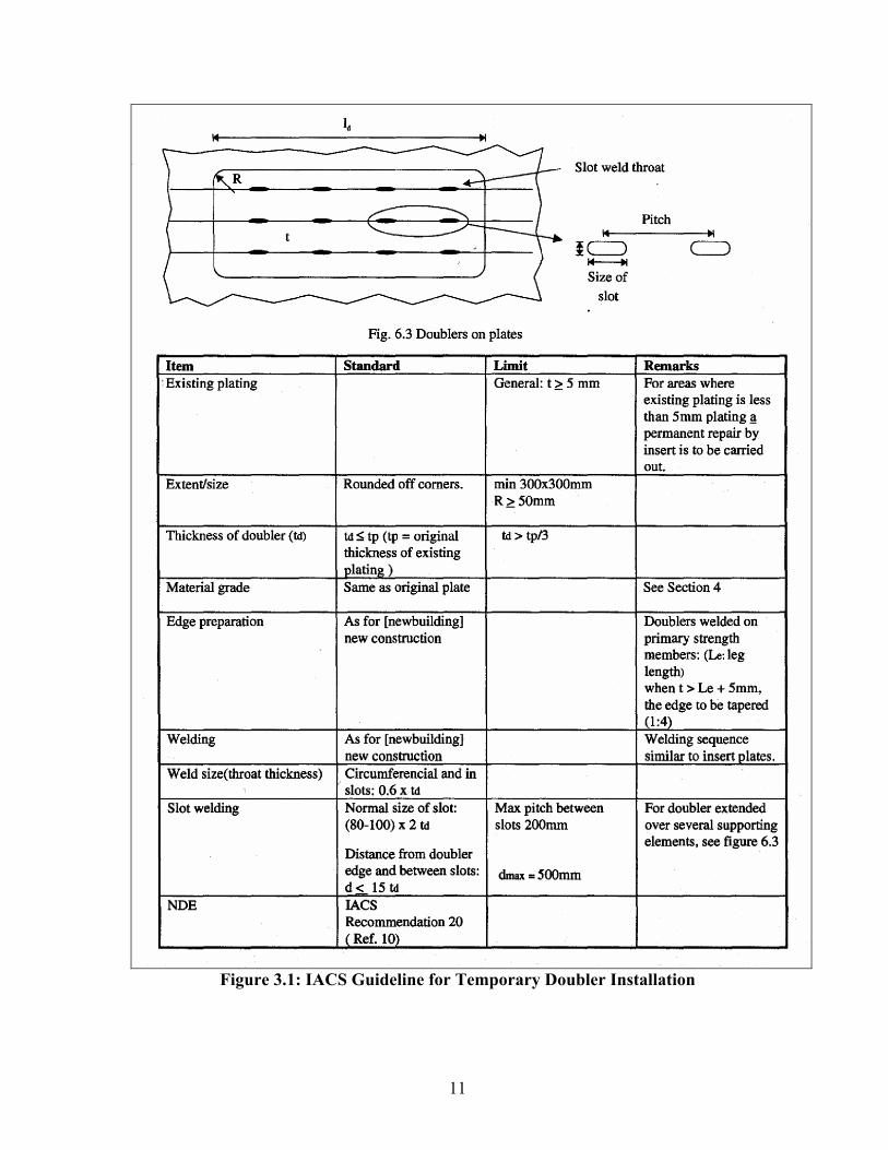
Each of the class societies that provided information on installing doublers indicated some version of a scheme utilizing perimeter fillet welds with an array of slot welds over the area of the doubler. This is similar to the IACS guidelines (See Fig. 3.1), which provide the most complete description of doubler installation. These guidance notes suggest that the doubler plate thickness should be between 1 and 1/3 times the original plate thickness being covered.

10
The corners of the doubler plate should be rounded to have a radius greater than 50mm and the doubler plate welds are required to have throats greater than 60% of the doubler thickness. While it is noted that the doubler plate should be at least 300 x 300 mm in size the relative sizing of the doubler with respect to a corrosion feature being repaired is not restricted. The recommendations provide some guidance on the sizing of doublers but do not provide any reference indicating how they were derived.
One variation on this received from one of the class societies was a requirement to provide lines of slot welds spaced at no more than 12” in both directions. Another variation received was to have larger slots (6”x 2”) in line with the deck longitudinals with a slot pitch roughly equal to the longitudinal frame spacing. A third variant was essentially the IACS requirement with the addition of slots in line with the plate stiffening in both directions. Otherwise, where the information was provided it was in line with the IACS guidance. Table 3.1 summarizes guidelines from various classification societies for allowable metal loss in various components of ship structure. This information is of significance to this study since the focus of the investigation is the use of doubler plates as a corrosion repair. This background provides some indication as to the corrosion features that would be repaired. It is noted however that the limits shown in this table are the maximum allowable, thus it is conceivable that a larger corrosion feature might be identified and because of its size be repaired with a doubler. In general, the allowable wastage in plating is 20% of the original plate thickness.
11
Figure 3.1: IACS Guideline for Temporary Doubler Installation

12
Table 3.1: Structural Scantling Diminution
Component Lloyds ABS BV NK GL* USCG MSA,UK Comments
Top Area 10% Plates
15% Longitudinals
15% 20%20%
+ 1mm
- 20% 20% or less -
Bottom Area 10% Plates
15% Longitudinals
20% 20%20%
+ 1mm
- 20% 20% or less -
Deck Plates 10% Plates
15% Longitudinals
20% 20%20%
+ 1mm
- 20% 20% or less -
Shear Strakes 20% 20% 20%20%
+ 1mm
- 20% 20% or less -
Shell Plates 20% 25% 20%20%
+ 1mm
- 20% 20% or less -
Bulge Strake Plates 20% 25% 20% 25% - 20% 20% or
less -
Bottom Plates 20% 25% 20% 25% - 20% 20% or less -
Transverse Bulkhead
Plates 20% 25% 15% 25% - 15% 20% or
less -
Internals including
Longitudinals, Girders,
Transverse struts,
Bulkhead Webs and Stringers,
Brackets and Hatch Side
Girders
20% 25% 20% 30% -
30% or 0.14"
whichever is less
20% or less
Flanges – 15% Bulkhead Stiffeners: Web- 15% Flange – 10% Bracket 15% (BV)
Under deck Box Girders
(Longitudinal or Transverse)
- 15% - - - - 20% or less -
Hatch Covers 20% 30% 20% - - 20% 20% or less -

13
1] IACS doesn't provide any specific limit of scantling diminution in the latest Bulk Carriers Guidelines for Surveys, Assessment and Repair of Hull Structure. 2] Det Norske Veritas (DNV) assesses each scantling of the vessel on the basis of their computer model and generally varies from one component to another in the range of 15-20%. 3] The above limits apply only when the Buckling Strength of the structure is within acceptable limits. 4] Bureau Veritas (BV) limits will apply provided scantling diminution of the structural components in a transverse zone do not exceed limits (10% top or bottom zone and 15% neutral axis zone) 5] Gerrmanischer Lloyds (GL) recommends:
- Section Modulus reduction no more than 10%. - Large surface reduction for t ≤ 11.5 mm is 1.5 mm - For t≥ 11.5 mm acceptable reduction = 0.09t+0.45mm (max. 3mm), where,‘t’ is the plate
or original plate thickness. - The permissible local reduction is no more than 20%
3.1.4 Summary of Additional Remarks and Opinions Expressed During Class Society
Interviews
The following are short summaries of additional information received in discussion with the class society personnel. 3.1.4.1 Class Society 1
This class indicated that doublers can be used for permanent repair in some instances, and for temporary repairs it is almost always acceptable. However, where petroleum or any other flammable liquid is being carried, they will not allow doublers to be used for repair on any cargo tank boundary or structure internal to the cargo tanks. Their main concern is safety, since it may be possible to trap liquid or gas between the two plates. This situation could lead to dangerous explosions during welding or during later repair efforts. In ballast tanks, though, they are willing to consider doublers. In fact, for the flanges of stiffeners where material is needed to restore section modulus or increase it, they allow doublers on the stiffener flanges. On plates they are less willing to accept doublers, they normally require the removal and insertion of plates. They are quite concerned about doublers being applied to badly corroded and pitted plate where the ability to weld properly and to create attachment to primary structure of sufficient strength would be in question. The person interviewed offered his opinion that in his experience, the extra work of preparing the base plate and then doing all the welding required for a doubler makes inserts the more cost effective solution and that as a result doublers are rarely used except in pure compression situations such as pillars, masts, etc. When asked if any work had been done to investigate the structural behavior of doublers he indicated that nothing specific had ever been done. In FE (Finite Element) analysis that included doublers they have merely used the combined plate thickness value based on the assumption that sufficient slot welding will make the two plates act as one.

14
3.1.4.2 Class Society 2
This class society indicated that before the enhanced survey programs (ESP) were begun, doublers were sometimes allowed for repair, although even then in tankers and bulkers they were not common. They indicated that among the major operators there has been a reluctance to use doublers for a long time, and now there are essentially no places where class will allow doublers to be used as a permanent repair. They indicated that this is certainly the case for major structure in the midship regions, but it was indicated that towards the extremes of the ship it does becomes more of a gray area and doublers may be allowed in these areas at times. However, doublers can be used as a temporary fix for most situations. The person interviewed indicated that in his opinion doublers are not a very attractive options to owners for whom the prospect of doing the repair twice (doublers though easier than inserts are still not cheap) is an overall expensive option. Therefore, doublers are not often used. However, his opinion is that a doubler can often be an efficient way to make repairs and add material, and that it is worth considering doublers more often as a permanent solution. 3.1.4.3 Class Society 3
This class society provided the internal guidance they use for the application of doubler plates as a permanent repair. The guidelines are as follows: Doublers shall not be used in the following locations:
- External plating in bottom, sides and upper deck except as given under "doublers may be used".
- Longitudinals on tank- or cargo hold boundaries, such as deck, sides, bottom or longitudinal bulkheads.
- Plating or internals in cargo tanks. - Boundaries between cargo/bunker tanks and the exterior. - Deterioration or corrosion on main frames in cargo holds of bulk carriers. - Cracks in existing plating. - Doublers should preferably be avoided in the aft peak area, due to the risk for
development of vibration cracks along the edges of the doubler. - Doublers shall not be used in connection with flat bar deck longitudinals within 0.5 L
amidships. Doublers may be used:
Doublers may be used to a limited extent in permanent repair, if not in conflict with above, as compensation for reduced plate thickness in:
- Internal structure except as described under "doublers not to be used".

15
- Inner bottom plating. - Upper deck in peak areas. - Tween deck plating.
3.2 Shipyards
Shipyards and ship owners were contacted and interviewed to gather information about doubler plate repairs. The list of shipyards and ship owners contacted are listed in Table 3.2 and Table 3.3, respectively. Two questionnaires were developed by the D&P team of engineers to obtain data on the use of doubler plates in commercial and naval shipbuilding. This was done to ensure that the data collected was consistent. A first contact questionnaire was developed to see whether the shipyard/ ship owners: a) used doubler plates for repair, and b) if they were interested in this study. The second questionnaire was used during the personal interviews. These questionnaires are provided in Appendix A. All the parties surveyed and interviewed were assured their anonymity. Each shipyard / ship owners listed in Table 3.1 and Table 3.2 were contacted and 12 interviews were granted. Most of the other shipyards contacted do not use doubler plates for ship repair. The questionnaire was prepared in such a way that it would depict the intent of the study and also collect the relevant information that would be used to develop cases for the finite element study. The questionnaire had 3 main sections: section 1 was used to collect data regarding their experience in installing doubler plates, section 2 contained questions regarding their experiences with previously installed doublers. Section 2 was developed to gather condition information on previously installed doublers at the time of dry-dock. The condition of doublers would reflect the performance of such repairs. The last section (section 3) was used to collect general notes and interviewees recommendations regarding the use of doubler plates as a means of permanent/temporary repair. All together twenty six (26) questions were asked. The interviews were conducted to obtain data on the use of doubler plates with regard to the following details:
• Type of damage repaired • Location of doubler plate repair • Expected life span (permanent/temporary) • Size and thickness of doubler plates • Doubler plate corner radii • Use of slot welds • Shipyard/ship owner recommendation

16
Table 3.2: List of Shipbuilders Contacted for Interviews
Shipyard P.O.C. Address City State Phone
Bender Steven Jones 265 S. Water St Mobile AL 251-431-8000 251 431-8769Atlantic Marine Shipyard Neville Rush Dunlap Dr Mobile AL 251-690-7100Eastern Shipbuilding 2200 Nelson Street Panama City FL 850 763-1900Tampa Bay Harry Bell/Steven Derrimine 1130 McClosky Blvd Tampa FL 813 248-9310 813 248-7290 International Ship Repair 1616 Penny lane Tampa FL 813 247-1118Halter Marine Sid Mizell 14055 Seaway Rd Gulfport MS 228-896-0029Halter Marine Carlos Del Real 228 897-4906Bollinger (multiple locations) Larry Vauclin 806 Bollinger Lane Amelia LA 985 631-3600 985 498-0353Bollinger (multiple locations) David Cole 606 Ford Industrial Road Amelia LA 985 631-2020 985 637-5341Bollinger (multiple locations) Charlie Herbert Lockport LAConrad Industries AJ Blanchard 110 Brashear Avenue Morgan City LA 985 702-0195 985 631-2395 985 397-1615North American Shipbuilding Gary Rook Galliano LA 985 632-7144
NORSHIPCOJay MatthewsDesign Engineer 750 W. Berkley Ave. Norfolk VA 757-494-4595
Metro MachineScott HenryProject Engineer Imperial Docks, Foot of Ligon St. Norfolk VA 757-494-0778 373-0615 cell
Colonna's ShipyardStephen WalkerVP Operations 400 E. Indian River Rd Norfolk VA
757-545-2414Ext 391 [email protected]
MHIJim CalvinQA Manager 543 E. Indian River Road Norfolk VA 757-222-4855
Earl IndustriesCliff SeeleyQA Director 826 Mount Vernon Avenue Portsmouth VA
904-249-3540Ext 14
USCG ELC 2401 Hawkins Road Curtis Bay MD 410 762-6000Baltimore Marine industries Hank Jones 600 Shipyard Road Baltimore MD 410 477-7652 410 456-9899
NASSCO Jay Carson 2789 Harbor Dr San Diego CA 619-544-3500SouthWest Marine San Diego CA 619Continental Maritime 1995 Bay Front Street San Diego CA 619 234-8851

17
Table 3.3: List of Ship Owners Contacted for Interview
Shipyard P.O.C. Address City State PhoneAlaska Marine Highway System 3132 Channel Dr Juneau AK 907-465-3955Crowley Marine Services Mr. Paul Murphy Pier D, Berths D47-D49 Long Beach CA 562-491-4752 c)310-849-6719Crowley 155 Grand Ave Oakland CA 510-251-7500Baylink Ferries of Vallejo California Transporation Div. 555 Santa Clara St Vallejo CA 877-64-FERRYWashington State Ferries Susan Harris 2911 Second Ave Seattle WA 206-515-3460Holland America Cruise Lines Mike Novak 300 Elliot Ave West Seattle WA 206-281-3535Pacific Fishermen, Inc. Doug Dixon 5351 24th Ave NW Seattle WA 206784-2562
ConocoPhillips Marine - Polar Tankers Mr. Frank Lee 600 N. Dairy Houston TX 832-379-6216Exxon Mobil/SeaRiver Maritime Pete Weber 13501 Katy Freeway Houston TX 281-870-6000Canal Barge Company 835 Union St New Orleans LA 504-581-2424Tidewater 601 Poydras St New Orleans LA 800-678-8433 504-568-1010Crowley Liner Services Capt. Cole Cosgrove 9487 Regency Square Blvd. Jacksonville FL 904-727-2615 904-727-2254Great Western Steamship Company 18245 SE Federal Hwy Tequesta FL 561-747-8888 877-553-3497
Navios David Elsy 20 Marshall St South Norwalk CT 203-354-1300Donjon Marine 1250 Liberty Ave Hillside NJ 908-964-8812Horizon Lines, LLC Michael Bohlman 1700 Galloping Hill Rd Kenilworth NJ 908-259-2803Keystone Shipping Company Pat Finsterbusch One Bala Plaze East, Ste. 600 Bala Cynwyd PA 610-617-6922Moran Towing Corp. Michael Nesbitt 444 Collins Dr Springfield PA 610-543-3430American Automar/Osprey Ship Mgmt Chris Nette or Paul Hagstrom 6550 Rock Spring Dr Bethesda MD 301-571-8500Maersk Line Ltd Capt. Carl Olderich 120 Corporate Blvd. Ste 400 Norfolk VA 757-852-3222

18
A brief summary of the findings from the survey is presented below. These findings are also summarized in Table 3.4; the actual survey responses are provided in Appendix B. 3.2.1 Type of damage repaired
It was found that most of the time doubler plates were used to repair damages due to local wastage, pitting, and cracks. Generally cracks are drilled, welded and then lapped with doublers. In some cases doublers were used to repair the holes. In some cases doublers were used to repair other corroded doublers. In one instance a shipyard mentioned that they had seen 4 layers of doubler plates one on top of another. 3.2.2 Location of doubler plate repair
Most respondents stated that the repair was carried out almost everywhere (except fuel tanks), four shipyards responded saying that they perform repairs only above the waterline. 3.2.3 Expected life span (permanent/temporary)
Seven out of twelve respondents said that they thought the doubler plate repairs were permanent. Four shipyards responded saying doublers would last for the life time of the ship and two put the life-span between 10-15 years. Others stated that the repairs were temporary until the ships were dry-docked for permanent repair. 3.2.4 Size and thickness of doubler plates
According to the responses, size of the doubler plates varied from as small as 3 inch in diameter to a 8’ x 40’ plate. One shipyard responded stating that most repairs in their yard are for doubler plates of 3’ x 3’ or higher. It was found that 1/4 inch, 5/16 inch, and 3/8 inch thick doubler plates were used by most of the shipyards. In some shipyards, doublers up to 1½ inch thick were used. Usually the thickness of the doubler plate is less than or equal to that of the parent plate.
3.2.5 Doubler plate corner radii
All shipyards stated that the corners of the doubler plates were rounded to avoid stress concentrations. The most common corner radius was found to be 3 inches. 3.2.6 Use of slot welds

19
Most respondents agreed that large and wide doubler plates should be attached using both fillet welds all around the plate and slot welds. The minimum spacing of the slot welds was 12 inches. Some shipyards applied slot welds only on top of the stiffeners supporting the damaged plate. Sizes of the slot welds used by shipyards varied significantly. For narrow doubler plates, only normal fillet welds are used; 6011/7018 rods were found to be the most common filler material. 3.2.7 Shipyard/ship owner recommendations
Ten out of twelve shipyards responded stating that they would like to see more repairs using doubler plates. They also recommended use of doubler plates for permanent repairs. According to them if the repairs with doubler plates are carried out properly, they do not cause future problems and can last for a long time. Most shipyards thought that doubler plates were the most cost effective way to repair damage. Two shipyards preferred inserts in lieu of doubler plates.

20
Table 3.4: Summary of Responses Gathered during Interviews
(LW – Local Wastage; P – Pitting; C – Cracks; LB – Local Buckling)

21
Table 3.4: Summary of Responses Gathered during Interviews (cont.)

22
4.0 TECHNICAL APPROACH
4.1 INTRODUCTION
Appropriate guidelines for designing and applying doubler plate repairs to ship structures will be established using as a minimum the following criteria:
• Allowable Stress • Buckling strength • Doubler plate weldment fatigue and fracture assessment
The main objective of this project was to investigate the geometric limits of doubler plates for stiffened panels and define appropriate design guidelines for their application. The project objective related to the development of doubler geometric limits was developed in two steps by considering the fatigue and fracture performance of stiffened panels with doubler plates and considering the buckling resistance of the repaired stiffened panel. It is noted that the investigation reported herein was limited in its scope and thus involved a number of geometric limits and analysis assumptions including:
• all of the analyses assumed linear elastic structural behavior and thus all of the material was assumed to have the same material properties,
• while some of the reported results are applicable to other structural configurations this study focused on the repair of corrosion features in plating of a stiffened panel,
• the analyses focused on a single angle stiffener / panel geometry (as outlined in Figures 5.1 and 5.2)
• the corrosion features considered were assumed to be flat bottom rectangular thickness reductions in the parent plating,
• the doubler circumferential welds were assumed to have leg lengths equal to the thickness of the doubler plate and thus the throat would be 70 percent of the doubler thickness rather than the IACS recommended 60%, and
• the structural loading considered included independent evaluations of the plate surface pressure, and the effects of longitudinal tension and compression loading.
In all cases the performance of the doubler repair system was considered in terms of its relative behavior. This means that the repair behavior was compared to that of the uncorroded stiffened panel or that of other repair geometries. This method of analysis was selected because the in-service loading of the generic structural assembly being considered can vary widely based upon its location within a vessel, the vessel operational profile and the overall vessel configuration.
23
4.2 Eigenvalue (Linear) Buckling Analysis
The eigenvalue linear buckling analysis was carried out to estimate the critical buckling load of the structure subjected to compressive loading in the plane of plating. The objective of this element of the presented work is to demonstrate the effectiveness of doubler plates in repairing corrosion damage from the stand point of stiffened panel buckling resistance. The scope of this analysis considered the effect of:
• doubler to base plate thickness ratio, • corrosion feature location w.r.t. stiffener, and • doubler plate versus corrosion feature geometry.
4.3 Fatigue and Fracture Analysis
In this element of the project, linear elastic static finite element analysis was carried out to estimate the hot spot stresses at weld toes, when the structure is subjected to tensile and lateral pressure loads. The hot spot stress was chosen as a reasonable indicator of the local stress concentration and thus an indicator of the potential for fatigue and fracture. The objective of the reported work is to demonstrate the sensitivity of:
• doubler corner radius, • doubler to base plate thickness ratio, • corrosion feature location w.r.t. stiffener, and • slot welds.
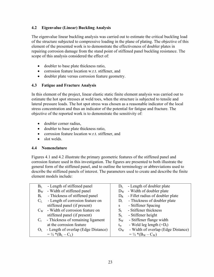
4.4 Nomenclature
Figures 4.1 and 4.2 illustrate the primary geometric features of the stiffened panel and corrosion feature used in this investigation. The figures are presented to both illustrate the general form of the stiffened panel, and to outline the terminology or abbreviations used to describe the stiffened panels of interest. The parameters used to create and describe the finite element models include:
BL - Length of stiffened panel BW - Width of stiffened panel Bt - Thickness of stiffened panel CL - Length of corrosion feature on
stiffened panel (if present) CW - Width of corrosion feature on
stiffened panel (if present) Ct - Thickness of remaining ligament
at the corrosion feature OL - Length of overlap (Edge Distance)
= ½ *(BL – CL)
DL - Length of doubler plate DW - Width of doubler plate DR - Fillet radius of doubler plate Dt - Thickness of doubler plate s - Stiffener Spacing St - Stiffener thickness SL - Stiffener height SW - Stiffener flange width tw - Weld leg length (=Dt) OW - Width of overlap (Edge Distance)
= ½ *(BW – CW)

24
BL
BW
DL
DW
DR CL
CW
Doubler Plate
Fillet WeldStiffened Panel
Corrosion feature on Stiffened Panel s
Stiffeners
Figure 4.1: Schematic of Stiffened Panel Geometry - Plan View
Fillet Weld
Bt
Dt
Ct
Doubler
Stiffened Panel tw
SL
SW
St
Stiffeners
Figure 4.2: Schematic of Stiffened Panel Geometry - Elevation View

25
5.0 EIGENVALUE LINEAR BUCKLING ANALYSIS
The eigenvalue linear buckling analysis is used to determine buckling (critical) loads at which the stiffened panel structure becomes unstable. There are two techniques available to perform buckling analysis – nonlinear and eigenvalue (or linear) buckling analysis. Eigenvalue (linear) buckling analysis predicts the theoretical buckling strength (the bifurcation point) of an ideal linear elastic structure. This technique is generally used when the structure appears long and slender and is thin-walled. For the current scope of work the eigenvalue buckling technique has been used.
5.1 Finite Element Model
The stiffened panel, doubler plate, stiffeners and welds are modeled using ANSYS Solid45 (8 node brick) elements for the linear buckling analysis. One element through thickness has been used. A refined mesh region with element size t x t x t in the vicinity of weld toe region is used to capture the local stresses in the structure. A sensitivity study was completed to demonstrate the effect of using 20 noded brick elements, for increased accuracy, as opposed to the 8 noded brick elements. This review indicated that the solution time for the 20 noded brick element models was substantially higher with no significant change in the analysis results. Therefore to make the FE modeling process more efficient, 8 noded brick elements have been used. Figures 5.1 and 5.2 illustrate the general geometry and element layout in the FE models used in this investigation along with the coordinate axes. The FE model boundary conditions are illustrated in Figure 5.3.
Figure 5.1: FE Model of Corroded Stiffened Plate with Doubler
Y Z

26
Figure 5.2: Solid Element Mesh Refinement
UZ = 0
UZ = 0
UY = 0
UX = 0
UY = 0Z
X
Y
Figure 5.3: Boundary Conditions Applied to the FE Model
5.2 Geometry
In order to develop an understanding of the effects of welding a doubler plate to
strengthen or compensate for a corrosion feature, a range of doubler plate thicknesses and corrosion aspect ratios were considered. The corrosion feature aspect ratio is defined as ratio of length of the corroded area to its width. For a constant corrosion feature width (152.4, 457.2 and 762 mm), aspect ratios of 4, 2, 1 and 0.5 were considered. The size (length and width) of the corrosion feature determines the size of the doubler (i.e. the larger the corrosion area the larger the doubler). Based on the design considerations in Section 3.1.3, the doubler edge distances of 25.4, 50.8, 101.6 and 254 mm were considered and doubler thickness was assumed to be 100%, 75% and 50% of the stiffened panel thickness. Table 5.1 illustrates the

27
corroded stiffened panel geometry parameters that are assumed to be constant for the purpose of analysis. Table 5.5 summarizes the geometry variables of stiffened panels investigated in this study along with the buckling strength and load factor results. Intent of this study was to investigate stiffened plate panels with 18”, 24”, 30”, and 36” stiffener spacing. However, due to time and budget limitations this study was restricted to single stiffener spacing of 36”. Mode shapes for few selected cases are shown in Appendix C (Figures C.1 through C.8).
Table 5.1: Constant Stiffened Panel Geometric Parameters Used in Buckling Analysis
Stiffened Plate, mm (inches) Stiffener ('L'shape )Size, mm (inches)
Length, BL
Width, BW
Thick, Bt Spacing 's' Thickness, St
Height, SL Width,
SW
3657.6 (144.0)
1828.8 (72.0)
12.7 (0.5)
914.4 (36.0)
12.7 (0.5)
177.8 (7.0)
101.6 (4.0)
5.3 Material Model
Due to the linear elastic nature of the investigation, the material behavior model used in this investigation was straight forward. A linear elastic material model based upon modulus of elasticity (E) of 207,000 MPa and Poisson’s ratio of 0.3 is used for the uncorroded and corroded stiffened panel FE models.
5.4 Loading
The stiffened panel finite element models, used to estimate buckling resistance, were subjected to a uni-axial compressive load (x-direction) of 1 N. The nominal applied loads were applied to indicate the sense and direction of the applied loading for the eigenvalue buckling resistance solution process. The eigenvalues calculated and reported by the ANSYS buckling analysis represent buckling load factors (multiples of the applied loading). Therefore, by using a unit applied load, the load factors represent the buckling load.
5.5 Buckling Analysis Results
5.5.1 Effect of Corrosion Features on Buckling Strength of Stiffened Panels – Analysis Baseline
The buckling strength of stiffened panels, with and without corrosion features, was analyzed to develop the desired doubler plate sizing recommendations. The uncorroded stiffened panel buckling load was used to normalize the results generated for the stiffened panels with corrosion features. Table 5.2 provides the geometric parameters describing the uncorroded baseline stiffened panel geometry and defines the buckling load for the panel. Table 5.3

28
describes the geometry of corroded stiffened panels without doubler plates that were used as reference points in the analysis. These models represent the unrepaired structural systems and the table presents the buckling load for the panels. Due to the presence of metal loss, a corroded plate offers less resistance to buckling than an uncorroded plate. A greater volume or extent of metal loss would be expected to lower the buckling strength of the stiffened panel.
Table 5.2: Buckling Strength of Uncorroded Stiffened Panel
Stiffened Panel, mm
Doubler Thickness,
mm
Corroded Feature, mm
Doubler to corrosion
edge distance
Critical Buckling
Load Case No.
BL BW Bt Dt CW CL Ct mm kN A 3657.6 1828.8 12.7 - - - - 2913
Table 5.3: Buckling Strength of Corroded Stiffened Panel without Doubler
Stiffened Panel, mm
Doubler Thickness,
mm
Corroded Feature, mm
Doubler to
corrosion edge
distance
Critical Buckling
Load Case No.
BL BW Bt Dt CW CL Ct mm kN 10a 3657.6 1828.8 12.7 - 152.4 76.2 9.525 - 2864 26a 3657.6 1828.8 12.7 - 457.2 914.4 9.525 - 2633
For the corroded stiffened panel analysis case identified as 10a in Table 5.3, Figure 5.4 illustrates the effect of the corrosion feature and doubler repair on the buckling strength of the stiffened panel. In this sample calculation the doubler plate is 12.7 mm thick and extends 50.8 mm beyond the corrosion feature in length and width (see Tables 5.4 and 5.5 for analysis case 10). It is noted that the addition of a doubler plate to the sample corroded stiffened panels effectively restores the buckling resistance above that associated with the original design. This improvement in buckling capacity is due to the additional cross sectional area (stiffness) afforded by the doubler plate.

29
2000
2500
3000
3500
4000
SP SP-WC SP-WC-WDType of Stiffened Panel
Cri
tical
Buc
klin
g L
oad,
kN
Case 10
SP: Uncorroded Stiffened PanelSP-WC: Corroded Stiffened PanelSP-WC-WD: Corroded Stiffened Panel with Doubler
Figure 5.4: Effect of Corrosion and Doubler on Buckling Strength
Also, Table 5.4 illustrates that for a stiffened panel with a constant corrosion feature, the larger the doubler thickness higher the buckling strength. This behavior is only illustrated for two thicknesses and was found generally to be true for most cases analyzed in this study.
Table 5.4: Effect of Doubler Thickness on Buckling Strength
Stiffened Panel, mm
Doubler Thickness,
mm
Corroded Feature, mm
Doubler to
corrosion edge
distance
Critical Buckling
Load, Case No.
BL BW Bt Dt CW CL Ct mm kN 10 3657.6 1828.8 12.7 12.7 152.4 304.8 9.525 50.8 3045 10b 3657.6 1828.8 12.7 9.525 152.4 304.8 9.525 50.8 3027
With the above general trends illustrated, the sections that follow seek to define the
most appropriate doubler dimensions to ensure that the doubler repair fully restores the buckling resistance of the corroded stiffened panel.
5.5.2 Buckling Load Factor
A buckling load factor is defined as the ratio of the critical buckling load of a corroded stiffened panel with doubler to critical buckling of the uncorroded stiffened panel with no doubler under similar loading conditions.

30
doubler no with plate base uncorroded a of load buckling Criticaldoubler with plate base corroded a of load buckling Critical Factor Load Buckling =
This parameter is used to evaluate the effectiveness of using a doubler on a corroded stiffened panel. For the doubler to be effective the buckling load factor should be greater than or equal to 1 (e.g. the doubler restores the panel structural integrity). Buckling strength and load factor results for stiffened panels containing a range of corrosion features and doubler plates are summarized in Table 5.5. The analyses are completed for a single corrosion feature depth (Ct) with a range of doubler plate thicknesses.

31
Table 5.5: Buckling Resistance Results for a Corroded Stiffened Panel
Doubler to corrosion
edge distance
Critical Buckling
LoadThickness
Ct
Width CW
Length CL mm kN
1 12.7 9.525 152.4 76.2 25.4 2971 1.022 12.7 9.525 152.4 76.2 50.8 3001 1.033 12.7 9.525 152.4 76.2 101.6 3059 1.054 12.7 9.525 152.4 76.2 254 3125 1.075 12.7 9.525 152.4 152.4 25.4 2987 1.036 12.7 9.525 152.4 152.4 50.8 3017 1.047 12.7 9.525 152.4 152.4 101.6 3074 1.068 12.7 9.525 152.4 152.4 254 3130 1.079 12.7 9.525 152.4 304.8 25.4 3014 1.03
10 12.7 9.525 152.4 304.8 50.8 3045 1.0511 12.7 9.525 152.4 304.8 101.6 3099 1.0612 12.7 9.525 152.4 304.8 254 3142 1.0813 12.7 9.525 152.4 609.6 25.4 3059 1.0514 12.7 9.525 152.4 609.6 50.8 3091 1.0615 12.7 9.525 152.4 609.6 101.6 3117 1.0716 12.7 9.525 152.4 609.6 254 3176 1.0917 9.525 9.525 457.2 228.6 25.4 3090 1.0618 9.525 9.525 457.2 228.6 50.8 3114 1.0719 9.525 9.525 457.2 228.6 101.6 3132 1.0820 9.525 9.525 457.2 228.6 254 3286 1.1321 9.525 9.525 457.2 457.2 25.4 3123 1.0722 9.525 9.525 457.2 457.2 50.8 3129 1.0723 9.525 9.525 457.2 457.2 101.6 3145 1.0824 9.525 9.525 457.2 457.2 254 3332 1.1425 9.525 9.525 457.2 914.4 25.4 3150 1.0826 9.525 9.525 457.2 914.4 50.8 3161 1.0927 9.525 9.525 457.2 914.4 101.6 3188 1.0928 9.525 9.525 457.2 914.4 254 3469 1.1929 9.525 9.525 457.2 1828.8 25.4 3311 1.1430 9.525 9.525 457.2 1828.8 50.8 3353 1.1531 9.525 9.525 457.2 1828.8 101.6 3457 1.1932 9.525 9.525 457.2 1828.8 254 4129 1.4233 6.35 9.525 762 381 25.4 3193 1.134 6.35 9.525 762 381 50.8 3228 1.1135 6.35 9.525 762 381 101.6 3256 1.1236 6.35 9.525 762 381 254 1878 0.6437 6.35 9.525 762 762 25.4 3143 1.0838 6.35 9.525 762 762 50.8 2798 0.9639 6.35 9.525 762 762 101.6 2241 0.7740 6.35 9.525 762 762 254 1288 0.44
Case No.
Doubler Thickness
Dt, mm
Corroded Feature, mm Buckling Load
Factor

32
Table 5.5: Buckling Resistance Results for a Corroded Stiffened Panel (cont.)
Doubler to corrosion
edge distance
Critical Buckling
LoadThickness
Ct
Width CW
Length CL mm kN
41 6.35 9.525 762 1524 25.4 2296 0.7942 6.35 9.525 762 1524 50.8 2097 0.7243 6.35 9.525 762 1524 101.6 1761 0.644 6.35 9.525 762 1524 254 1109 0.3845 6.35 9.525 762 3048 25.4 1890 0.6546 6.35 9.525 762 3048 50.8 1719 0.5947 6.35 9.525 762 3048 101.6 1434 0.4948 6.35 9.525 762 3048 254 881 0.333a 12.7 9.525 762 381 25.4 3289 1.1334a 12.7 9.525 762 381 50.8 3330 1.1435a 12.7 9.525 762 381 101.6 3349 1.1536a 12.7 9.525 762 381 254 3413 1.1737a 12.7 9.525 762 762 25.4 3356 1.1538a 12.7 9.525 762 762 50.8 3398 1.1739a 12.7 9.525 762 762 101.6 3422 1.1740a 12.7 9.525 762 762 254 3517 1.2141a 12.7 9.525 762 1524 25.4 3566 1.2242a 12.7 9.525 762 1524 50.8 3636 1.2543a 12.7 9.525 762 1524 101.6 3715 1.2844a 12.7 9.525 762 1524 254 4069 1.445a 12.7 9.525 762 3048 25.4 4789 1.6446a 12.7 9.525 762 3048 50.8 4692 1.6147a 12.7 9.525 762 3048 101.6 4672 1.648a 12.7 9.525 762 3048 254 4649 1.634b 9.525 9.525 762 381 50.8 3375 1.1638b 9.525 9.525 762 762 50.8 3299 1.1342b 9.525 9.525 762 1524 50.8 3589 1.2346b 9.525 9.525 762 3048 50.8 4040 1.3949 12.7 6.35 762 3048 50.8 2075 0.7150 12.7 7.7 762 3048 50.8 3114 1.0751 12.7 11.7 762 3048 50.8 5234 1.852 9.525 6.35 762 3048 50.8 1887 0.6553 9.525 7.7 762 3048 50.8 2816 0.9754 9.525 11.7 762 3048 50.8 4639 1.5955 6.35 6.35 762 3048 50.8 1501 0.5256 6.35 7.7 762 3048 50.8 1591 0.5557 6.35 11.7 762 3048 50.8 1881 0.65
Case No.
Doubler Thickness
Dt, mm
Corroded Feature, mm Buckling Load
Factor

33
5.5.3 Effect of Doubler Size and Thickness
For Cases 1 to 16 (Table 5.5), where the thickness of doubler is equal to thickness of stiffened panel, the buckling load factor is greater than 1 indicating that the strength of the corroded stiffened panel is restored through the application of a doubler plate (Figure 5.5). Also it can be seen that increasing corrosion aspect ratio has no significant effect on the strength of the corroded stiffened panel. For doublers with thickness equal to the nominal thickness of the parent material and a constant corrosion feature aspect ratio, Figure 5.5 illustrates that as the doubler size increases there is a slight increase in the buckling strength of the corroded stiffened panel.
Bt= 12.7 mm, Cw = 152.4 mm, Ct = 9.525 mm, Dt =12.7 mm
0.0
0.5
1.0
1.5
2.0
0 50 100 150 200 250 300
Doubler to Corrosion Edge Distance, mm
Buc
klin
g L
oad
Fact
or
0.5124
Corrosion Aspect Ratio (CL/CW)
Figure 5.5: Buckling Load Factor for Dt = 12.7 mm; CW = 152.4 mm
Based upon the results of analyses 17 to 32 (Table 5.5), where the thickness of the doubler plate is equal to the thickness of corroded feature, the buckling load factor is always greater than 1 indicating that the strength of the corroded stiffened panel is restored through the application of the doubler (Figure 5.6). Over the range of values evaluated, as the corrosion aspect ratio and doubler size increases, the buckling strength of the corroded stiffened panel increases slightly. Also for a constant corrosion aspect ratio, the buckling strength increases with increase in doubler edge distance. The effect of doubler edge distance on the buckling strength of stiffened panel is more pronounced for corrosion aspect ratio of 4.

34
Bt= 12.7 mm, Cw = 457.2 mm, Ct = 9.525 mm, Dt =9.525 mm
0.0
0.5
1.0
1.5
2.0
0 50 100 150 200 250 300
Doubler to Corrosion Edge Distance, mm
Buc
klin
g L
oad
Fact
or
0.5124
Corrosion Aspect Ratio (CL/CW)
Figure 5.6: Buckling Load Factor for Dt = 9.525 mm; CW = 457.2 mm
For Cases 33 to 48 (Table 5.5) where the thickness of doubler plate is less than the thickness of the remaining ligament of the corroded feature, Figure 5.7 illustrates that the buckling load factor for corrosion aspect ratios of 2 and 4 (Corrosion length > Corrosion width) is less than 1 indicating ineffectiveness of the doubler in repairing the corrosion damage. As the corrosion aspect ratio and doubler size increases, the buckling strength of the corroded stiffened panel decreases significantly. This suggests that having a doubler plate that is significantly larger in size than the corrosion feature but thinner than the corroded patch, is not an effective repair solution. For corrosion aspect ratios of 0.5 and 1 (Corrosion length ≤ Corrosion width), a small size doubler is more effective than a larger doubler. Overall the buckling strength of the corroded stiffened panel drops when thickness of the doubler is less than the thickness at the corrosion feature.

35
Bt= 12.7 mm, Cw = 762 mm, Ct = 9.525 mm, Dt =6.35 mm
0.0
0.5
1.0
1.5
2.0
0 50 100 150 200 250 300
Doubler to Corrosion Edge Distance, mm
Buc
klin
g L
oad
Fact
or0.5124
Corrosion Aspect Ratio (CL/CW)
Figure 5.7: Buckling Load Factor for Dt = 6.35 mm; CW = 762 mm
For scenarios where the buckling load factor is less than 1 (Figure 5.7), indicating ineffectiveness of the doubler, a thicker doubler can be used to provide the necessary buckling strength to the corroded stiffened panel. Figure 5.8 illustrates effectiveness of using a thicker doubler plate.
Bt= 12.7 mm, Cw = 762 mm, Ct = 9.525 mm, Dt =12.7 mm
0.0
0.5
1.0
1.5
2.0
0 50 100 150 200 250 300
Doubler to corrosion edge distance, mm
Buc
klin
g L
oad
Fact
or
0.5124
Corrosion Aspect Ratio (CL/CW)
Figure 5.8: Buckling Load Factor for Dt = 12.7 mm; CW = 762 mm

36
Based upon the results presented in Table 5.5 and Figures 5.5 through 5.8, it is apparent that, for doubler thickness of 12.7 and 9.525 the doubler edge distance, over the range of values investigated is not a significant factor affecting the buckling resistance. Considering issues related to cost and space for welding for larger doublers, a doubler edge distance of 50.8 mm is recommended. It is also noted that the doubler plate geometries investigated did not demonstrate the need for slot welds, however, these additional doubler to base plate attachments may be necessary for larger or deeper corrosion features. 5.5.4 Doubler Thickness Factor
The following section is included to define the doubler thickness required to repair a stiffened panel corrosion feature. To study the effect of loss of stiffened panel thickness on its buckling strength, ‘Doubler Thickness Factor’ has been introduced. Doubler Thickness factor is defined as:
Thickness FeatureCorroded-ThicknessPanelStiffenedUncorrodedThicknessDoubler Factor ThicknessDoubler =
The calculated doubler thickness factors are listed in Table 5.6. The ranges of parameters listed in the Table 5.6 were selected to permit evaluation of the effect of doubler plate thickness on the effectiveness of corrosion repair scenarios. Figure 5.9 illustrates the effect of the doubler thickness factor on buckling load factor of 762 mm wide corroded stiffened panels.
Table 5.6: Doubler Thickness Factor
Case Type Uncorroded
Stiffened Panel thickness (mm)
Doubler Plate thickness
(mm)
Corrosion feature
thickness (mm)
Doubler thickness
factor
1 12.7 12.7 9.525 4 2 12.7 9.525 9.525 3 3 12.7 6.35 9.525 2

37
Bt = 12.7 mm; Corrosion Width = 762 mm; Corrosion thickness = 9.525 mm; Doubler to corrosion edge distance = 50.8 mm
0.0
0.5
1.0
1.5
2.0
1 2 3 4 5
Doubler Thickness Factor = Dt/(Bt-Ct)
Buc
klin
g L
oad
Fact
or
0.5124Critical Buckling Load Factor
Corrosion Aspect Ratio (CL/CW)
Figure 5.9: Effect of Doubler Thickness Factor
Increasing the doubler thickness increases the buckling strength of the corroded stiffened panel. Based upon the results shown in Figure 5.9, it is suggested that the most appropriate doubler thickness can be defined based upon doubler thickness factor. For effective buckling strength it is suggested that for a corroded stiffened panel doubler thickness factor be more than 2.6. This would mean that if the thickness of the corroded patch were 9.525mm then the thickness of doubler plate should be at least 8.255mm [2.6*(12.7-9.525)] to restore the buckling strength. Doubler plate thickness for a corroded patch of 6.35mm would need a doubler that is 16.51mm thick.
5.6 Effect of Corrosion
Figure 5.10 illustrates the effect of thickness of the corroded feature on buckling load factor of corroded stiffened panel. As the metal loss increases beyond 25%, the buckling strength of stiffened panel is reduced drastically.

38
Bt = 12.7 mm; CW = 762 mm; CL = 3048 mm; Doubler to Corrosion Edge Distance = 50.8 mm
0.0
0.5
1.0
1.5
2.0
2 4 6 8 10 12 14
Doubler Thickness, mm
Buc
klin
g L
oad
Fact
or
11.79.5257.76.35
Corrosion Thickness, Ct, mm
Figure 5.10: Effect of Corrosion
Stiffened panels with corrosion features greater than 25% of their plate thickness should be repaired permanently and use of doubler plate is not recommended. For metal loss less than or equal to 25%, the figure above indicates that an 8mm doubler thickness would restore the effectiveness of the panel with regards to buckling resistance. Based upon this result it is suggested that the doubler thickness be at least 65% (approx 8mm / 12.7mm) of the stiffened panel plate thickness.
5.7 Conclusions for Buckling Analysis
Based upon the cases analyzed and the results that were generated, the following conclusions for restoring the buckling strength of a stiffened plate with a doubler are presented:
• For doubler thickness greater than or equal to the thickness of the corroded patch (Dt=12.7 mm and 9.525 mm), an increase in corrosion aspect ratio has no adverse effect on the buckling strength of the corroded stiffened panel.
• For doubler thicknesses less than the thickness of the corroded patch (Dt=6.35 mm),
the increase in corrosion feature aspect ratio lowers the buckling strength of the repaired corroded panel.

39
5.8 Doubler Recommendations for Corroded Stiffened Panel
Based upon the analyses completed and the results that were generated, the following recommendations for restoring the buckling strength of a stiffened plate with a doubler are presented:
• For metal loss greater than 25% of the parent plate thickness, the use of doublers is not recommended.
• To restore the buckling resistance of a stiffened panel, the doubler plate thickness should be greater than the larger of:
o 65% of the original stiffened panel plate thickness (Dt > 0.65*Bt) o thickness determined by the doubler thickness factor 2.6 (i.e. 2.6*(Bt - Ct))
• The doubler size (length and width), doubler plate edge distance can be any value but care should be taken to minimize the size of the doubler plate. It is recommended that a 50mm (2 inch) corrosion feature to doubler edge distance be used. It is noted that larger doubler plates will need slot welds to ensure stability.
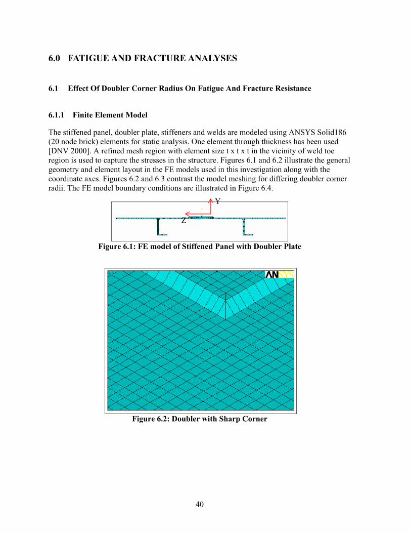
40
6.0 FATIGUE AND FRACTURE ANALYSES
6.1 Effect Of Doubler Corner Radius On Fatigue And Fracture Resistance
6.1.1 Finite Element Model
The stiffened panel, doubler plate, stiffeners and welds are modeled using ANSYS Solid186 (20 node brick) elements for static analysis. One element through thickness has been used [DNV 2000]. A refined mesh region with element size t x t x t in the vicinity of weld toe region is used to capture the stresses in the structure. Figures 6.1 and 6.2 illustrate the general geometry and element layout in the FE models used in this investigation along with the coordinate axes. Figures 6.2 and 6.3 contrast the model meshing for differing doubler corner radii. The FE model boundary conditions are illustrated in Figure 6.4.
Figure 6.1: FE model of Stiffened Panel with Doubler Plate
Figure 6.2: Doubler with Sharp Corner
Y
Z

41
Figure 6.3: Doubler with Corner Radius
UZ = 0
UZ = 0
UY = 0
UX = 0
UY = 0Z
X
Y
Figure 6.4: Boundary Conditions Applied to the FE Model
6.1.2 Geometry
In order to develop an understanding of the effects of corner radius on stress distribution of the stiffened panel, a range of doubler and doubler plate corner radii were considered. Doubler thickness is assumed to be 100%, 75% and 50% of stiffened panel thickness. Doubler corner radiuses of 50.8, 101.6 and 152.4 mm were considered. The stiffened panel is assumed to be uncorroded. Table 6.2 summarizes the geometries investigated and results for hot spot stress analysis.

42
6.1.3 Material Model
Due to the linear elastic nature of the investigation, the material behavior model used in this investigation was straight forward. A linear elastic material model based upon modulus of elasticity (E) of 207,000 MPa and Poisson’s ratio of 0.3 is used for the uncorroded and corroded stiffened panel FE models. 6.1.4 Hot Spot Stress Analysis
A hot spot stress analysis approach is used to consider the expected relative fatigue performance of the stiffened panel. The hot spot stress approach considers the principal stress as affected by all stress concentration factors except that induced by the weld toe geometry. In these analyses, the hot spot stress is calculated at the weld toe locations P1 (at corner of doubler) and P2 (center of doubler) for doubler corner radii of 25.4, 50.8 and 152.4 mm. The stress at weld toe is linearly extrapolated from those at distance t/2 and 3t/2 from weld toe, where,‘t’ is the thickness of stiffened panel. Figure 6.5 illustrates the hot spot stress locations (P1 and P2) considered for analysis.
Figure 6.5: Hot Spot Stress Locations
6.1.5 Loading
The stiffened panel is subjected to a uni-axial tensile edge pressure (x-direction) of 75.84 MPa. Since the objective of this work is to develop an understanding of the nature of the

43
stress concentration, or damaging effects of the doubler corner radius, the applied loading can be considered based upon a notional or unit applied loading. 6.1.6 Hot Spot Stress Results
The results for hot spot stress analysis for various geometries are summarized in Table 6.1. To evaluate the fatigue life at location P1, S-N approach is used. The basic design S-N curve is given as:
log N = log a – m log ∆σ
where N is the predicted number of cycles to failure for stress range ∆σ is the stress range m is the negative inverse slope of S-N curve = 3 log a is the intercept of log N-axis by S-N curve = 13 The details presented are based upon assumptions outlined in Table 2.11 of DNV standard for fatigue assessment of ship structures. As the corner of the doubler is most likely location for crack initiation, fatigue assessment is carried out at location P1 and cycles to failure is shown in Table 6.1. Stress plots for few selected cases are shown in Appendix C (Figures C.9 through C.12).

44
Table 6.1: Hot Spot Stress Summary
Case No Stiffened Panel, mm Stiffener Size, mm Doubler Size, mm Hot Spot Stress
'σX' MPa Cycles to
failure
BL BW Bt s SL SW St DL DW Dt DR P1 P2 P1
A 3657.6 1828.8 12.7 914.4 177.8 101.6 12.7 1016 508 12.7 0 151.67 109.69 2.87E+06
1A 3657.6 1828.8 12.7 914.4 177.8 101.6 12.7 1016 508 12.7 50.8 119.99 111.65 5.79E+06
2A 3657.6 1828.8 12.7 914.4 177.8 101.6 12.7 1016 508 12.7 101.6 107.22 113.76 8.11E+06
3A 3657.6 1828.8 12.7 914.4 177.8 101.6 12.7 1016 508 12.7 152.4 104.39 117.60 8.79E+06
B 3657.6 1828.8 12.7 914.4 177.8 101.6 12.7 1016 508 9.525 0 134.94 109.03 4.07E+06
4B 3657.6 1828.8 12.7 914.4 177.8 101.6 12.7 1016 508 9.525 50.8 112.14 109.61 7.09E+06
5B 3657.6 1828.8 12.7 914.4 177.8 101.6 12.7 1016 508 9.525 101.6 102.96 111.29 9.16E+06
6B 3657.6 1828.8 12.7 914.4 177.8 101.6 12.7 1016 508 9.525 152.4 99.01 114.58 1.03E+07
C 3657.6 1828.8 12.7 914.4 177.8 101.6 12.7 1016 508 6.35 0 114.97 104.94 6.58E+06
7C 3657.6 1828.8 12.7 914.4 177.8 101.6 12.7 1016 508 6.35 50.8 104.09 105.68 8.87E+06
8C 3657.6 1828.8 12.7 914.4 177.8 101.6 12.7 1016 508 6.35 101.6 96.06 106.77 1.13E+07
9C 3657.6 1828.8 12.7 914.4 177.8 101.6 12.7 1016 508 6.35 152.4 93.04 109.17 1.24E+07
G 3048 1524 9.525 762 152.4 101.6 9.525 1016 508 9.525 0 160.79 108.04 2.41E+06
10G 3048 1524 9.525 762 152.4 101.6 9.525 1016 508 9.525 50.8 120.36 109.96 5.74E+06
11G 3048 1524 9.525 762 152.4 101.6 9.525 1016 508 9.525 101.6 105.75 111.87 8.46E+06
12G 3048 1524 9.525 762 152.4 101.6 9.525 1016 508 9.525 152.4 103.41 115.47 9.04E+06
H 3048 1524 9.525 762 152.4 101.6 9.525 1016 508 7.144 0 140.00 107.85 3.64E+06
13H 3048 1524 9.525 762 152.4 101.6 9.525 1016 508 7.144 50.8 113.78 108.06 6.79E+06
14H 3048 1524 9.525 762 152.4 101.6 9.525 1016 508 7.144 101.6 104.28 109.58 8.82E+06
15H 3048 1524 9.525 762 152.4 101.6 9.525 1016 508 7.144 152.4 99.85 112.67 1.00E+07
I 3048 1524 9.525 762 152.4 101.6 9.525 1016 508 3.572 0 104.82 100.01 8.68E+06
16I 3048 1524 9.525 762 152.4 101.6 9.525 1016 508 3.572 50.8 97.15 101.02 1.09E+07
17I 3048 1524 9.525 762 152.4 101.6 9.525 1016 508 3.572 101.6 91.78 101.74 1.29E+07
18I 3048 1524 9.525 762 152.4 101.6 9.525 1016 508 3.572 152.4 89.86 103.50 1.38E+07
6.1.6.1 Effect of Doubler Corner Radius on Fatigue Strength of Stiffened Panel at
Location P2
As the corner radius of the doubler is increased, the net cross sectional area of the doubler at its leading edge reduces. Based upon the reduction in cross sectional area, the weld toe stress at location P2 increases with increase in doubler corner radius (Figures 6.6 and 6.7). This would serve to reduce the fatigue life of the doubler plate system. It is noted that the increase in hot spot stress at location P2 is less than 10%, for the cases investigated, and thus may not be a significant factor in the deign of doubler plate repair systems.

45
Bt = 12.7 mm
60
80
100
120
140
160
180
0 20 40 60 80 100 120 140 160
Doubler corner radius, mm
Hot
Spo
t Str
ess 'σ x
', M
Pa
P2 @ Doubler Thickness = 12.7 mmP2 @ Doubler Thickness = 9.525 mmP2 @ Doubler Thickness = 6.35 mm
Figure 6.6: Effect of DR on Hot Spot Stress at P2 @ Bt = 12.7 mm
Bt = 9.525 mm
60
80
100
120
140
160
180
0 20 40 60 80 100 120 140 160
Doubler corner radius, mm
Hot
Spo
t Str
ess 'σ x
', M
Pa
P2 @ Doubler Thickness = 9.525 mmP2 @ Doubler Thickness = 7.144 mmP2 @ Doubler Thickness = 3.572 mm
Figure 6.7: Effect of DR on Hot Spot Stress at P2 @ Bt = 9.525 mm

46
6.1.6.2 Effect of Doubler Corner Radius on Fatigue Strength of Stiffened Panel at Location P1
As the corner radius of the doubler is increased, the sharpness of the corner decreases and one would expect the fatigue life of the corner to increase with the reduction in the local stress. Figures 6.8 and 6.9 illustrate the effect of corner radius on hot spot stress and fatigue strength of stiffened panel location P1. The reduction in hot spot stress at location P1 translates into an increase in fatigue life as shown in Figures 6.10 and 6.11. The changes in fatigue life resulting from changes in doubler corner radius are significant at the corner of the doubler plate.
Bt = 12.7 mm
60
80
100
120
140
160
180
0 20 40 60 80 100 120 140 160
Doubler corner radius, mm
Hot
Spo
t Str
ess 'σ x
', M
Pa
P1 @ Doubler Thickness = 12.7 mmP1 @ Doubler Thickness = 9.525 mmP1 @ Doubler Thickness = 6.35 mm
Figure 6.8: Effect of DR on Hot Spot Stress at P1 @ Bt = 12.7 mm

47
Bt = 9.525 mm
60
80
100
120
140
160
180
0 20 40 60 80 100 120 140 160
Doubler corner radius, mm
Hot
Spo
t Str
ess 'σ x
', M
Pa
P1 @ Doubler Thickness = 9.525 mmP1 @ Doubler Thickness = 7.144 mmP1 @ Doubler Thickness = 3.572 mm
Figure 6.9: Effect of DR on Hot Spot Stress at P1 @ Bt = 9.525 mm
Bt = 12.7 mm
0.0E+00
5.0E+06
1.0E+07
1.5E+07
0 20 40 60 80 100 120 140 160
Doubler corner radius, mm
Cyc
les t
o fa
ilure
P1 @ Doubler Thickness = 12.7 mmP1 @ Doubler Thickness = 9.525 mmP1 @ Doubler Thickness = 6.35 mm
Figure 6.10: Effect of DR on Fatigue Life at P1 @ Bt = 12.7 mm

48
Bt = 9.525 mm
0.0E+00
5.0E+06
1.0E+07
1.5E+07
0 20 40 60 80 100 120 140 160
Doubler corner radius, mm
Cyc
les t
o fa
ilure
P1 @ Doubler Thickness = 9.525 mmP1 @ Doubler Thickness = 7.144 mmP1 @ Doubler Thickness = 3.572 mm
Figure 6.11: Effect of DR on Fatigue Life at P1 @ Bt = 9.525 mm
6.1.6.3 Effect of Doubler Thickness on Fatigue Strength of Stiffened Panel at Location P1
For a constant corner radius as the thickness of the doubler is increased, the weld toe stress at location P1 increases. The rate at which the P1 location hot spot stress increases with doubler thickness is inversely related to the corner radius. In other words, the deleterious effect of thicker doubler plates is more pronounced for smaller corner radii as shown in Figures 6.12 and 6.13. The increase in local stress is maintained below 10% for all doubler thicknesses investigated as long as the corner radius of the doubler is greater than 50.8 mm.
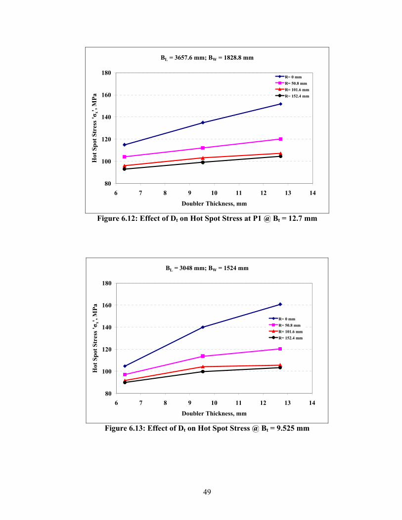
49
BL = 3657.6 mm; BW = 1828.8 mm
80
100
120
140
160
180
6 7 8 9 10 11 12 13 14
Doubler Thickness, mm
Hot
Spo
t Str
ess 'σ x
', M
Pa
R= 0 mmR= 50.8 mmR= 101.6 mmR= 152.4 mm
Figure 6.12: Effect of Dt on Hot Spot Stress at P1 @ Bt = 12.7 mm
BL = 3048 mm; BW = 1524 mm
80
100
120
140
160
180
6 7 8 9 10 11 12 13 14
Doubler Thickness, mm
Hot
Spo
t Str
ess 'σ x
', M
Pa
R= 0 mmR= 50.8 mmR= 101.6 mmR= 152.4 mm
Figure 6.13: Effect of Dt on Hot Spot Stress @ Bt = 9.525 mm

50
6.1.7 Conclusions for Doubler Corner Radius
Based upon the analyses completed and the results presented, increasing doubler corner radius reduces stresses at the corners (location P1) of doubler plate, however, increasing doubler corner radius increases the stresses at the leading edge (location P2) of the doubler plate. In order to optimize a design, one would select the corner radius that produced similar fatigue lives (hot spot stresses) at the corner (location P1) and leading edge (location P2) of the doubler plate. Figures 6.14 to 6.19 illustrate the most “effective” corner radius for various doubler thicknesses. 6.1.7.1 Stiffened Panel Plate Thickness = 12.7 mm
The effective corner radius for the doubler decreases as doubler thickness decreases. For doubler thickness of 12.7 mm, 9.525 mm and 6.35 mm the effective corner radiuses are 79 mm, 62 mm and 42 mm, respectively (Figures 6.14 to 6.16).
BL = 3657.6 mm; BW = 1828.8 mm;Dt = 12.7 mm
60
80
100
120
140
160
180
0 20 40 60 80 100 120 140 160
Doubler corner radius, mm
Hot
Spo
t Str
ess 'σ x
', M
Pa
Location P1Location P2
Effective doubler corner radius
Figure 6.14: Doubler Thickness = 12.7 mm

51
BL = 3657.6 mm; BW = 1828.8 mm;Dt = 9.525 mm
60
80
100
120
140
160
180
0 20 40 60 80 100 120 140 160
Doubler corner radius, mm
Hot
Spo
t Str
ess 'σ x
', M
Pa
Location P1Location P2
Effective doubler corner radius
Figure 6.15: Doubler Thickness = 9.525 mm
BL = 3657.6 mm; BW = 1828.8 mm;Dt = 6.35 mm
60
80
100
120
140
160
180
0 20 40 60 80 100 120 140 160
Doubler corner radius, mm
Hot
Spo
t Str
ess 'σ x
', M
Pa
Location P1
Location P2
Effective doubler corner radius
Figure 6.16: Doubler Thickness = 6.35 mm

52
6.1.7.2 Stiffened Panel Plate Thickness = 9.525 mm
The effective corner radius for the doubler decreases as doubler thickness decreases. For doubler thickness of 9.525 mm, 7.144 mm and 3.572 mm the effective corner radiuses are 84 mm, 78 mm and 30 mm respectively (Figures 6.17 to 6.19).
DL = 3048 mm; DW = 1524 mm;Dt = 9.525 mm
60
80
100
120
140
160
180
0 20 40 60 80 100 120 140 160
Doubler corner radius, mm
Hot
Spo
t Str
ess 'σ x
', M
Pa
Location P1Location P2
Effective doubler corner radius
Figure 6.17: Doubler Thickness = 9.525 mm
BL = 3048 mm; BW = 1524 mm;Dt = 7.144 mm
60
80
100
120
140
160
180
0 20 40 60 80 100 120 140 160
Doubler corner radius, mm
Hot
Spo
t Str
ess 'σ x
', M
Pa
Location P1Location P2
Effective doubler corner radius
Figure 6.18: Doubler Thickness = 7.144 mm

53
BL = 3048 mm; BW = 1524 mm;Dt = 3.572 mm
60
80
100
120
140
160
180
0 20 40 60 80 100 120 140 160
Doubler corner radius, mm
Hot
Spo
t Str
ess 'σ x
', M
Pa
Location P1Location P2
Effective doubler corner radius
Figure 6.19: Doubler Thickness = 3.572 mm
6.1.8 Recommendations for Doubler Corner Radius
Based upon the results shown in Figures 6.14 through 6.19 it is suggested that the most appropriate doubler corner radius (DR) can be defined based upon the ratio of the doubler thickness (Dt) and parent plate thickness (Bt). Table 6.2 summarizes the results from Figures 6.14 to 6.19. This relationship is defined in the equation shown in Figure 6.20 developed based upon a simple linear regression of the analysis results where R has units of mm. This equation may be used to define the most appropriate doubler corner radius for a range of plate thicknesses.
Table 6.2: Effect of Doubler to Base Plate Thickness Ratio
Bt, mm Dt, mm DR optimal, mm Dt/Bt
12.7 12.7 79 1 12.7 9.525 62 0.75 12.7 6.35 42 0.5 9.525 9.525 84 1 9.525 7.14 78 0.749619.525 3.572 30 0.37501

54
DR = 82.4 (Dt/Bt) + 2.46
0
10
20
30
40
50
60
70
80
90
0.2 0.3 0.4 0.5 0.6 0.7 0.8 0.9 1
Thickness Ratio (Dt/Bt)
Rec
omm
ende
d D
oubl
er C
orne
r R
adiu
s, D
R
(mm
)
Figure 6.20: Recommended Doubler Corner Radius
If a constant corner radius is desired for all combinations of thickness, then it is suggested that a 75mm (3in) corner radius should be used.

55
6.2 Effect Of Doubler Size On Fatigue And Fracture Resistance
In order to demonstrate the effect of doubler size on fatigue and fracture strength of a corroded stiffened panel; two loading scenarios are considered:
1) Uniaxial Tensile Edge Loading 2) Lateral Loading
The following sections describe the analysis and results for this task. As described in the previous section, a hot spot stress approach is used to evaluate the performance of the corroded stiffened panels. 6.2.1 Finite Element Model
The stiffened panel, doubler plate, stiffeners and welds are modeled using ANSYS Solid186 (20 node brick) elements for static analysis. One element through thickness has been used. A refined mesh region with element size t x t x t in the vicinity of weld toe region is used to capture the stresses in the structure. Figures 6.21 and 6.22 illustrate the general geometry and element layout in the FE models used in this investigation along with the coordinate axes. It is noted that the doubler corner is not treated with the same level of detail as in Section 5.0. This treatment will promote a local stress concentration at the corner of the doubler plate. This local effect, however, does not influence the results presented in this section. The FE model boundary conditions are illustrated in Figure 6.23.
Figure 6.21: FE model of Stiffened Panel with Doubler
Y
Z

56
Figure 6.22: Solid Element Mesh Refinement
UZ = 0
UZ = 0
UY = 0
UX = 0
UY = 0Z
X
Y
Figure 6.23: Boundary Conditions Applied to the FE Model
6.2.2 Geometry
In order to develop an understanding of the effects of welding a doubler plate to
strengthen a corroded stiffened panel, a range of doubler plate thicknesses and corrosion aspect ratios were considered. The corrosion aspect ratio is defined as ratio of length of the corroded area to its width. For a constant corrosion width, aspect ratios of 4, 2, 1 and 0.5 were considered. The size of the corrosion feature determines the size of the doubler (i.e. the larger the corrosion area the larger the doubler). The doubler plate thickness is assumed to be 100%, 75% and 50% of the thickness of the stiffened panel. Table 6.3 illustrates the corroded stiffened panel geometry parameters that are assumed to be constant for the purpose of

57
analysis. The results for various geometry variables investigated for the analysis under tensile and lateral loading scenarios are summarized in Tables 6.4 and 6.5, respectively.
Table 6.3: Constant Geometry Parameters for Doubler Plate Geometry Analysis
Stiffened Plate, mm Stiffener ('L'shape )Size, mm
Length, BL
Width, BW
Thick, Bt
Spacing 's'
Thickness, St
Height, SL
Width, SW
3657.6 1828.8 12.7 914.4 12.7 177.8 101.6 The analysis results suggested that for wide doublers, (e.g. Case 48 in Table 6.4) Figure 6.24, the doubler edge is close to panel edge and boundary effects may affect the results presented.
Figure 6.24: Load Case 48
6.2.3 Material Model
Due to the linear elastic nature of the investigation, the material behavior model used in this investigation was straightforward. A linear elastic material model based upon modulus of elasticity (E) of 207,000 MPa and Poisson’s ratio of 0.3 is used for the uncorroded and corroded stiffened panel FE models.

58
6.2.4 Hot Spot Stress Analysis
A hot spot stress approach is used to consider the expected relative fatigue performance of the stiffened panel. The hot spot stress approach considers the principal stress as affected by all stress concentration factors except that induced by the weld toe geometry. In these analyses, the hot spot stress is calculated at the weld toe location, P1 as illustrated in Figure 6.25. The stress at weld toe is linearly extrapolated from those at distance t/2 and 3t/2 from weld toe, where, ‘t’ is the thickness of stiffened panel. Stress plots for few selected cases are shown in Appendix C (Figures C.13 through C.18).
P1X
Z
t/2 3t/2
Base PlateDoubler
Figure 6.25: Hot Spot Stress Locations
6.2.5 Doubler Effectiveness
For a corroded stiffened panel the corroded area has the least strength and is most likely the site of crack initiation. For the doubler to be effective the average stress at the center of the corroded feature should be less than the hot spot stress at the weld toe .i.e.
Toe at Weld '' StressSpot Hot 2
X
BottomXTopX σσσ
<+
where σX Top and σX Bottom are the principal stress magnitudes at the top and bottom surface of the stiffened panel plate at the center of the corrosion feature. The location of crack initiation considered in this investigation is the weld toe. Figure 6.26 illustrates the locations for data collection from the FE models.

59
Doubler Plate
Corroded FeatureTopCenter
BottomCenter
Weld Toe
Figure 6.26: Effectiveness of Doubler
6.2.6 Loading
The stiffened panel is subjected to a uni-axial tensile edge loading (x-direction) of 75.84 Mpa and lateral pressure (y-direction) of 0.028 Mpa. Since the nature of the analysis is linear, notional or unit loads are usually sufficient. 6.2.7 Tensile Loading Results
The results for hot spot stress analysis for various geometries are summarized in Table 6.4. From the results presented in Table 6.4, we can see that the fatigue strength of the corroded stiffened panel subjected to a uni-axial tensile edge loading is enhanced by the use of doubler plate considering the potential for fatigue at the weld toe according to the definition outlined in Section 6.2.5.

60
Table 6.4: Hot Spot Stress Summary for Tensile Loading
Effectiveness of Doubler
(E–Effective,
mmWidth
CW
Length CL mm MPa Top Bottom Average NE–Not Effec.)
1 12.7 152.4 76.2 25.4 77.84 66.83 82.29 74.56 E
2 12.7 152.4 76.2 50.8 80.17 72.84 76.89 74.87 E
3 12.7 152.4 76.2 101.6 85.09 78.31 70.75 74.53 E
4 12.7 152.4 76.2 254 96.71 82.82 54.79 68.81 E
5 12.7 152.4 152.4 25.4 84.74 59.84 84.66 72.25 E
6 12.7 152.4 152.4 50.8 86.32 63.17 81.26 72.21 E
7 12.7 152.4 152.4 101.6 90.32 66.98 75.8 71.39 E
8 12.7 152.4 152.4 254 99.38 70.89 59.15 65.02 E
9 12.7 152.4 304.8 25.4 96.14 56.93 82.21 69.57 E
10 12.7 152.4 304.8 50.8 96.75 57.71 80.32 69.02 E
11 12.7 152.4 304.8 101.6 99.08 59.6 75.31 67.45 E
12 12.7 152.4 304.8 254 103.09 62.83 57.61 60.22 E
13 12.7 152.4 609.6 25.4 111.31 58.31 73.98 66.15 E
14 12.7 152.4 609.6 50.8 110.58 58.06 72.16 65.11 E
15 12.7 152.4 609.6 101.6 110.08 58.23 67.73 62.98 E
16 12.7 152.4 609.6 254 107.08 59.77 52.71 56.24 E
17 9.525 457.2 228.6 25.4 83.56 60.11 86.49 73.3 E
18 9.525 457.2 228.6 50.8 85.94 63.81 81.78 72.79 E
19 9.525 457.2 228.6 101.6 90.39 69.66 73.09 71.37 E
20 9.525 457.2 228.6 254 99.88 79.87 51.9 65.88 E
21 9.525 457.2 457.2 25.4 95.6 59.86 77.68 68.77 E
22 9.525 457.2 457.2 50.8 96.61 61.74 74.28 68.01 E
23 9.525 457.2 457.2 101.6 98.37 65.33 67.34 66.34 E
24 9.525 457.2 457.2 254 103.01 70.2 52.91 61.55 E
25 9.525 457.2 914.4 25.4 105.83 63.04 65.16 64.1 E
26 9.525 457.2 914.4 50.8 105.28 63.5 63.14 63.32 E
27 9.525 457.2 914.4 101.6 104.68 64.22 59.55 61.89 E
28 9.525 457.2 914.4 254 105.94 62.29 53.26 57.78 E
29 9.525 457.2 1828.8 25.4 109.01 62.11 61.28 61.69 E
30 9.525 457.2 1828.8 50.8 108.2 61.53 60.37 60.95 E
31 9.525 457.2 1828.8 101.6 107.21 60.44 58.74 59.59 E
32 9.525 457.2 1828.8 254 107.77 56.84 54.1 55.47 E
33 6.35 762 381 25.4 89.15 61.77 81.61 71.69 E
34 6.35 762 381 50.8 90.89 64.79 77.4 71.09 E
35 6.35 762 381 101.6 93.68 70.06 69.68 69.87 E
36 6.35 762 381 254 98.89 80.19 52.89 66.54 E
37 6.35 762 762 25.4 97.12 67.57 67.45 67.51 E
38 6.35 762 762 50.8 97.54 68.45 65.51 66.98 E
39 6.35 762 762 101.6 98.42 69.34 62.59 65.97 E
40 6.35 762 762 254 101.17 69.5 56.93 63.21 E
Hot Spot Stress 'SX'
Stress 'SX' in the Center of the Corroded Feature, MPa
Case No.
Doubler Thickness Dt
Corroded Feature, mm
Doubler to corrosion
edge distance

61
Table 6.4: Hot Spot Stress Summary for Tensile Loading (cont.)
Effectiveness of Doubler
(E–Effective,
mmWidth
CW
Length CL mm MPa Top Bottom Average NE–Not Effec.)
41 6.35 762 1524 25.4 100.65 67.59 63.02 65.3 E
42 6.35 762 1524 50.8 100.7 67.07 62.37 64.72 E
43 6.35 762 1524 101.6 101.08 65.68 61.42 63.55 E
44 6.35 762 1524 254 103.22 62.27 58.38 60.32 E
45 6.35 762 3048 25.4 103.61 64.65 63.73 64.19 E
46 6.35 762 3048 50.8 103.32 64.13 62.92 63.52 E
47 6.35 762 3048 101.6 101.88 62.91 61.49 62.2 E
48 6.35 762 3048 254 76.14 60.15 56.95 58.55 E
49 12.7 762 381 25.4 88.15 56.23 81.84 69.04 E
50 12.7 762 381 101.6 93.97 62.06 68.91 65.48 E
51 12.7 762 381 254 100.57 70.47 48.47 59.47 E
52 12.7 762 762 25.4 100.62 59.47 63.11 61.29 E
53 12.7 762 762 101.6 101.99 60.84 56.06 58.45 E
54 12.7 762 762 254 104.35 60.74 47.28 54.01 E
55 12.7 762 1524 25.4 106.72 58.46 54.47 56.47 E
56 12.7 762 1524 101.6 106.16 56.09 51.88 53.99 E
57 12.7 762 1524 254 106.99 51.74 47.46 49.6 E
58 9.525 152.4 76.2 25.4 79.2 67.65 82.67 75.16 E
59 9.525 152.4 76.2 50.8 81.85 73.49 77.41 75.45 E
60 9.525 152.4 76.2 101.6 87.08 79.04 71.22 75.13 E
61 9.525 152.4 152.4 25.4 85.74 61.19 84.15 72.67 E
62 9.525 152.4 152.4 50.8 87.55 64.41 80.92 72.67 E
63 9.525 152.4 152.4 101.6 91.73 68.22 75.67 71.95 E
64 9.525 152.4 304.8 25.4 95.98 58.96 80.94 69.95 E
65 9.525 152.4 304.8 50.8 96.91 59.76 79.14 69.45 E
66 9.525 152.4 304.8 101.6 99.46 61.69 74.46 68.08 E
67 9.525 152.4 609.6 25.4 107.59 60.99 73.14 67.06 E
68 9.525 152.4 609.6 50.8 107.62 60.76 71.5 66.13 E
69 9.525 152.4 609.6 101.6 108.04 61.15 67.48 64.31 E
Hot Spot Stress 'SX'
Stress 'SX' in the Center of the Corroded Feature, MPa
Case No.
Doubler Thickness Dt
Corroded Feature, mm
Doubler to corrosion
edge distance

62
6.2.7.1 Effect of Doubler Edge Distance and Corrosion Aspect Ratio on Hot Spot
Stress
The results presented in Figures 6.27 through 6.31 illustrate that for a constant corrosion aspect ratio (ratio of length of the corroded area to its width) as the size of the doubler increases, hot spot stress increases. These figures also indicate that for higher corrosion aspect ratios (CL> CW), the doubler plate edge does not have a significant effect on weld toe stresses. Therefore the doubler plate to corrosion feature edge distance can be any value. However, care should be taken to minimize the size of the doubler plate because large doubler plates will need slot welds to ensure stability. The results also indicate that as the corrosion feature aspect ratio increases the hot spot stress increases. At doubler to corrosion edge distance of 254 mm, the corrosion aspect ratio has less of an effect on the weld toe stress.
CW = 152.4 mm; Ct = 9.525 mm; Dt = 12.7 mm
0
40
80
120
160
0 50 100 150 200 250 300
Doubler to Corrosion Edge Distance, mm
Hot
Spo
t Str
ess 'σ x
', M
Pa
0.5124
Corrosion Aspect Ratio (CL /CW)
Figure 6.27: Effect of Doubler Size for Dt = 12.7 mm and CW = 152.4 mm

63
CW = 762 mm; Ct = 9.525 mm; Dt = 12.7 mm
0
40
80
120
160
0 50 100 150 200 250 300
Doubler to corrosion edge distance, mm
Hot
Spo
t Str
ess 'σ x
', M
Pa
0.512
Corrosion Aspect Ratio (CL /CW)
Figure 6.28: Effect of Doubler Size for Dt = 12.7 mm and CW = 762 mm
CW = 457.2 mm; Ct = 9.525 mm; Dt = 9.525 mm
0
40
80
120
160
0 50 100 150 200 250 300
Doubler to Corrosion Edge Distance, mm
Hot
Spo
t Str
ess 'σ x
', M
Pa
0.5124
Corrosion Aspect Ratio (CL /CW)
Figure 6.29: Effect of Doubler Size for Dt = 9.525 mm and CW = 457.2 mm

64
CW = 152.4 mm; Ct = 9.525 mm; Dt = 9.525 mm
0
40
80
120
0 50 100 150 200 250 300
Doubler to corrosion edge distance, mm
Hot
Spo
t Str
ess 'σ x
', M
Pa
0.5124
Corrosion Aspect Ratio (CL /CW)
v Figure 6.30: Effect of Doubler Size for Dt = 9.525 mm and Cw = 152.4 mm
CW = 762 mm; Ct =9.525 mm; Dt = 6.35 mm
0
40
80
120
160
0 50 100 150 200 250 300
Doubler to Corrosion Edge Distance, mm
Hot
Spo
t Str
ess 'σ x
', M
Pa
0.512
Corrosion Aspect Ratio (CL /CW)
Figure 6.31: Effect of Doubler Size for Dt = 6.35 mm and CW = 762 mm

65
For a constant doubler thickness and edge distance, a larger corrosion feature would increase weld toe hot spot stresses and thus lower the repaired stiffened panel fatigue strength as illustrated in Figure 6.32.
Dt = 12.7 mm; Ct = 9.525 mm; Doubler to corrosion edge distance = 254 mm
90
95
100
105
110
0 0.5 1 1.5 2 2.5
Corrosion Aspect Ratio (CL/CW)
Hot
Spo
t Str
ess 'σ x
', M
Pa
152.4762
Corrosion Width 'CW', mm
Figure 6.32: Effect of Corrosion on Hot Spot Stress
6.2.7.2 Effect of Doubler Thickness Factor
To study the effect of corrosion on strength of corroded stiffened panel, the ‘Doubler Thickness Factor’ introduced previously in section 2.5.4 was used.
Figures 6.33 and 6.34 illustrate the effect of doubler thickness factor on hot spot stress for a doubler plate edge distance of 50.8 mm. Figure 6.33 (Cw = 762 mm) shows that the hot spot stress increases with the doubler thickness factor where as Figure 6.34 (Cw = 152.4 mm) illustrates that the hot spot stress decreases with the doubler thickness factor. This indicates that as the width of the corroded feature increases i.e. edge of corrosion gets closer to the stiffener; a thinner doubler would generate lower weld toe stress.

66
CW = 762 mm; Ct = 9.525 mm; Doubler to Corrosion Edge Distance = 50.8 mm
60
70
80
90
100
110
120
0 1 2 3 4 5Doubler Thickness Factor = Dt/(Bt - Ct )
Hot
Spo
t Str
ess 'σ x
', M
Pa
0.512
CL/CW
Figure 6.33: Effect of Doubler Thickness Factor for CW = 762 mm
CW = 152.4 mm; Ct = 9.525 mm; Doubler to Corrosion Edge Distance = 50.8 mm
60
70
80
90
100
110
120
0 1 2 3 4 5Doubler Thickness Factor = Dt/(Bt - Ct )
Hot
Spo
t Str
ess 'σ x
', M
Pa
0.5124
CL/CW
Figure 6.34: Effect of Doubler Thickness Factor for CW = 152.4 mm

67
6.2.8 Lateral Loading Results
The results for hot spot stress analysis of a corroded stiffened panel subjected to lateral pressure for various doubler and corrosion geometries are summarized in Table 6.5. For Cases 1 to 3 and 48 in Table 6.5, it can be seen that as the doubler edge distance increases, average stress in center of the corroded region is less than that at the weld toe. In these cases the doubler repair would be considered ineffective. 6.2.8.1 Effect of Doubler Edge Distance and Corrosion Aspect Ratio on Hot Spot
Stress for CW = 152.4 mm
For a corrosion width of 16% of the stiffener spacing, as the corrosion aspect ratio increases, the hot spot stress increases. As the doubler to corrosion edge distance approaches 254 mm, the effect of corrosion aspect ratio diminishes (Figure 6.35 and 6.36). At doubler to corrosion edge distance of 254 mm, the corrosion aspect ratio has less effect on the weld toe stress.
CW = 152.4; Ct = 9.525 mm; Dt = 12.7 mm
0
20
40
60
0 50 100 150 200 250 300
Doubler to Corrosion Edge Distance, mm
Hot
Spo
t Str
ess 'σ x
', M
Pa
0.5124
Corrosion Aspect Ratio (CL/CW)
Figure 6.35: Effect of Doubler Size for Dt = 12.7 mm

68
Table 6.5: Hot Spot Stress Summary for Lateral Loading
Effectiveness of Doubler
(E–Effective,
mmWidth
CW
Length CL mm MPa Top Bottom Average NE–Not Effec.)
1 12.7 152.4 76.2 25.4 21.3 22.6 25.1 23.85 NE
2 12.7 152.4 76.2 50.8 21.24 24.78 22.63 23.7 NE
3 12.7 152.4 76.2 101.6 21.94 27.35 18.81 23.08 NE
4 12.7 152.4 76.2 254 25.42 34.48 1.9 18.19 E
5 12.7 152.4 152.4 25.4 23.18 19.88 24.8 22.34 E
6 12.7 152.4 152.4 50.8 23.08 21.22 23.22 22.22 E
7 12.7 152.4 152.4 101.6 23.73 23.41 19.68 21.55 E
8 12.7 152.4 152.4 254 26.18 30.41 2.16 16.29 E
9 12.7 152.4 304.8 25.4 27.76 17.51 22.55 20.03 E
10 12.7 152.4 304.8 50.8 27.27 18.18 21.77 19.97 E
11 12.7 152.4 304.8 101.6 27.3 20.08 18.59 19.33 E
12 12.7 152.4 304.8 254 27.05 27.62 0.52 14.07 E
13 12.7 152.4 609.6 25.4 34.56 17.87 17.19 17.53 E
14 12.7 152.4 609.6 50.8 33.37 17.97 16.51 17.24 E
15 12.7 152.4 609.6 101.6 31.85 18.91 13.91 16.41 E
16 12.7 152.4 609.6 254 26.91 25.98 -1.56 12.21 E
17 9.525 457.2 228.6 25.4 26.38 23.45 19.16 21.31 E
18 9.525 457.2 228.6 50.8 27 25.37 15.99 20.68 E
19 9.525 457.2 228.6 101.6 28.25 29.11 9.11 19.11 E
20 9.525 457.2 228.6 254 26.44 40.65 -11.7 14.48 E
21 9.525 457.2 457.2 25.4 29.88 25.27 13.01 19.14 E
22 9.525 457.2 457.2 50.8 30.17 26.68 10.21 18.45 E
23 9.525 457.2 457.2 101.6 30.28 30.02 3.67 16.85 E
24 9.525 457.2 457.2 254 25.83 39.25 -13.59 12.83 E
25 9.525 457.2 914.4 25.4 32.66 25.23 7.11 16.17 E
26 9.525 457.2 914.4 50.8 31.9 26.27 5.14 15.71 E
27 9.525 457.2 914.4 101.6 30.22 28.69 0.82 14.76 E
28 9.525 457.2 914.4 254 23.33 35.21 -10.63 12.29 E
29 9.525 457.2 1828.8 25.4 27.25 24.58 4.15 14.36 E
30 9.525 457.2 1828.8 50.8 26.06 24.92 3.22 14.07 E
31 9.525 457.2 1828.8 101.6 23.72 25.94 1.19 13.56 E
32 9.525 457.2 1828.8 254 17.11 30.76 -5.89 12.43 E
33 6.35 762 381 25.4 32.54 31.41 3.12 17.27 E
34 6.35 762 381 50.8 31.81 33.64 -0.16 16.74 E
35 6.35 762 381 101.6 30.72 37.74 -6 15.87 E
36 6.35 762 381 254 27.82 45.49 -16.4 14.54 E
37 6.35 762 762 25.4 31.61 40.46 -8.31 16.07 E
38 6.35 762 762 50.8 30.35 41.77 -10.27 15.75 E
39 6.35 762 762 101.6 28.57 43.27 -12.84 15.21 E
40 6.35 762 762 254 25.35 44.1 -15.06 14.52 E
Hot Spot Stress 'SX'
Stress 'SX' in the Center of the Corroded Feature, MPa
Case No.
Doubler Thickness Dt
Corroded Feature, mm
Doubler to corrosion
edge distance

69
Table 6.5: Hot Spot Stress Summary for Lateral Loading (cont.)
Effectiveness of Doubler
(E–Effective,
mmWidth
CW
Length CL mm MPa Top Bottom Average NE–Not Effec.)
41 6.35 762 1524 25.4 26.76 37.79 -5.15 16.32 E
42 6.35 762 1524 50.8 25.24 38.53 -6.15 16.19 E
43 6.35 762 1524 101.6 23.33 39.1 -7.35 15.88 E
44 6.35 762 1524 254 20.51 39.48 -8.74 15.37 E
45 6.35 762 3048 25.4 21.02 35.24 -2.68 16.28 E
46 6.35 762 3048 50.8 20.03 35.9 -3.47 16.22 E
47 6.35 762 3048 101.6 18.98 36.79 -4.63 16.08 E
48 6.35 762 3048 254 10.01 39.08 -6.78 16.15 NE
49 12.7 762 381 25.4 21.71 28.46 7.98 18.22 E
50 12.7 762 381 101.6 20.69 33.75 -3.59 15.08 E
51 12.7 762 381 254 18.69 42.04 -19.73 11.16 E
52 12.7 762 762 25.4 23.91 40.14 -11.28 14.43 E
53 12.7 762 762 101.6 20.76 42.79 -18.36 12.21 E
54 12.7 762 762 254 17.16 42.32 -22.4 9.96 E
55 12.7 762 1524 25.4 20.2 34.5 -9.31 12.6 E
56 12.7 762 1524 101.6 16.09 35.99 -12.93 11.53 E
57 12.7 762 1524 254 12.93 35.77 -15.1 10.33 E
58 9.525 152.4 76.2 25.4 26.18 22.83 23.33 23.08 E
59 9.525 152.4 76.2 50.8 26.41 25 20.98 22.99 E
60 9.525 152.4 76.2 101.6 27.46 27.6 17.28 22.44 E
61 9.525 152.4 152.4 25.4 27.9 20.2 23.21 21.71 E
62 9.525 152.4 152.4 50.8 28.09 21.63 21.59 21.61 E
63 9.525 152.4 152.4 101.6 29.03 23.91 18.07 20.99 E
64 9.525 152.4 304.8 25.4 31.93 18.3 20.94 19.62 E
65 9.525 152.4 304.8 50.8 31.76 19.04 20.11 19.58 E
66 9.525 152.4 304.8 101.6 32.08 21.04 16.96 19 E
67 9.525 152.4 609.6 25.4 36.99 19.33 15.66 17.49 E
68 9.525 152.4 609.6 50.8 36.29 19.46 15.03 17.24 E
69 9.525 152.4 609.6 101.6 35.3 20.57 12.59 16.58 E
Case No.
Doubler Thickness Dt
Corroded Feature, mm
Doubler to corrosion
edge distance
Hot Spot Stress 'SX'
Stress 'SX' in the Center of the Corroded Feature, MPa

70
CW = 152.4; Ct = 9.525 mm; Dt = 9.525 mm
0
20
40
60
0 50 100 150 200 250 300
Doubler to Corrosion Edge Distance, mm
Hot
Spo
t Str
ess 'σ x
', M
Pa
0.5124
Corrosion Aspect Ratio (CL/CW)
Figure 6.36: Effect of Doubler Size for Dt = 9.525 mm and CW = 152.4 mm
6.2.8.2 Effect of Doubler Edge Distance and Corrosion Aspect Ratio on Hot Spot Stress for CW = 457.2 mm
At corrosion width of 50% of the stiffener spacing (Figure 6.37), a doubler edge distance of 254 mm results in the lowest hot spot stress. Also at this edge distance, hot spot stress level drops with increase in corrosion aspect ratio.

71
CW = 457.2; Ct = 9.525 mm; Dt = 9.525 mm
0
20
40
60
0 50 100 150 200 250 300
Doubler to corrosion edge distance, mm
Hot
Spo
t Str
ess '
σx
', M
Pa
0.5124
Corrosion Aspect Ratio (CL/CW)
Figure 6.37: Effect of Doubler Size for Dt = 9.525 mm and CW = 457.2 mm
6.2.8.3 Effect of Doubler Edge Distance and Corrosion Aspect Ratio on Hot Spot Stress for CW = 762 mm
The combination of a larger doubler edge distance and a larger corrosion aspect ratio gives the lowest hot spot stress (Figures 6.38 and 6.39). As the doubler edge distance increases the hot spot stress level decreases. The hot spot stress decreases as the corrosion aspect ratio increases. The size of the doubler depends on the size of the corrosion feature; larger corrosion areas employ larger doubler plates. At corrosion width of 84% of the stiffener spacing, as the corrosion aspect ratio and doubler edge distance increases the size of the doubler increases thereby stiffening up the corroded panel and providing more resistance against lateral loading.

72
CW = 762 mm; Ct = 9.525 mm; Dt = 6.35 mm
0
20
40
60
0 50 100 150 200 250 300
Doubler to corrosion edge distance, mm
Hot
Spo
t Str
ess 'σ x
', M
Pa
0.512
Corrosion Aspect Ratio (CL/CW)
Figure 6.38: Effect of Doubler Size for Dt = 6.35 mm and CW = 762 mm
CW = 762 mm; Ct = 9.525 mm; Dt = 12.7 mm
0
20
40
60
0 50 100 150 200 250 300
Doubler to Corrosion Edge Distance, mm
Hot
Spo
t Str
ess 'σ x
', M
Pa
0.512
Corrosion Aspect Ratio (CL/CW)
Figure 6.39: Effect of Doubler Size for Dt = 12.7 mm and CW = 762 mm
6.2.8.4 Effect of Doubler Thickness Factor
Figures 6.40 and 6.41 illustrate the effect of doubler thickness factor on hot spot stress. It can be seen that a thicker doubler will reduce the hot spot stress and thus enhance the fatigue strength of corroded stiffened subjected to lateral loading.

73
CW = 762 mm; Ct = 9.525 mm; Doubler to Corrosion Edge Distance = 254 mm
10.0
20.0
30.0
40.0
50.0
0 1 2 3 4 5Doubler Thickness Factor = Dt/(Bt - Ct )
Hot
Spo
t Str
ess 'σ x
' MPa
0.512
CL/CW
Figure 6.40: Effect of Doubler Thickness Factor for CW = 762 mm
CW = 152.4 mm; Ct = 9.525 mm; Doubler to Corrosion Edge Distance = 101.6 mm
10.0
20.0
30.0
40.0
50.0
0 1 2 3 4 5Doubler Thickness Factor = Dt/(Bt - Ct )
Hot
Spo
t Str
ess 'σ x
' MPa
0.5124
CL/CW
Figure 6.41: Effect of Doubler Thickness Factor for CW = 152.4 mm

74
6.2.9 Combined Loading Effect (Tension + Lateral)
For a linear analysis, theoretically by superposition of hot spot stresses from tensile and lateral load cases, stresses generated from combined loading can be predicted. The application of combined loading would represent the worst case scenario. Tables 6.6 through 6.10 summarize the hot spot stress results for combined loading scenario (tension +lateral) for load cases from Table 6.4 and 6.5.
Table 6.6: Hot Spot Stress (MPa) @ Dt = 12.7 mm; CW = 152.4 mm
Doubler to Corrosion Edge Distance, mm Corrosion
Aspect Ratio 25.4 50.8 101.6 254
0.5 99 101 107 122 1 108 109 114 126 2 124 124 126 130 4 146 144 142 134
Table 6.7: Hot Spot Stress (MPa) @ Dt = 9.525 mm; CW = 457.2 mm
Doubler to Corrosion Edge Distance, mm Corrosion
Aspect Ratio 25.4 50.8 101.6 254
0.5 110 113 119 126 1 125 127 129 129 2 138 137 135 129 4 136 134 131 125
Table 6.8: Hot Spot Stress (MPa) @ Dt = 6.35 mm; CW = 762 mm
Doubler to Corrosion Edge Distance, mm Corrosion
Aspect Ratio 25.4 50.8 101.6 254
0.5 122 123 124 127 1 129 128 127 127 2 127 126 124 124 4 125 123 121 86

75
Table 6.9: Hot Spot Stress (MPa) @ Dt = 12.7 mm; CW = 762 mm
Doubler to Corrosion Edge Distance, mm Corrosion
Aspect Ratio 25.4 101.6 254
0.5 110 115 119 1 125 123 122 2 127 122 120
Table 6.10: Hot Spot Stress (MPa) @ Dt = 9.525 mm; CW = 152.4 mm
Doubler to Corrosion Edge Distance, mm Corrosion
Aspect Ratio 25.4 50.8 101.6
0.5 105 108 115 1 114 116 121 2 128 129 132 4 145 144 143
6.2.9.1 Effect of Doubler Edge Distance on Combined Loading
Figures 6.42 and 6.43 illustrate the effect of doubler edge distance on combined hot spot stress for Cw =152.4 mm and Cw = 762 mm, respectively, where Cw is the width of the corrosion feature. As noted earlier the results for the very large aspect ratio corrosion features (aspect ratio =4) are affected by the extents of the FE model and thus have a trend that does not agree well with those produced for smaller corrosion features. The results shown in Figure 6.42 (Cw =152.4 mm) indicates that in general the weld toe hot spot stress increases with doubler edge distances for corrosion feature aspect ration of 2 or less. For larger values of corrosion aspect ratio, the hot spot stress decreases as the doubler edge distance increases. Figure 6.43 (Cw = 762 mm) indicates that for corrosion aspect ratio of 0.5, the hot spot stress increases as the overlap between the base plate and doubler plate increases (i.e. with increase in corrosion edge distance). The hot spot stresses for higher corrosion aspect ratios decrease with the corrosion edge distance. From the inspection of these two figures, the doubler to corrosion edge distance should be kept less than 100 mm to minimize the effect of edge distance on fatigue life.

76
CW = 152.4 mm; Ct = 9.525 mm
80
100
120
140
160
20 40 60 80 100 120 140 160 180 200 220 240 260
Doubler to Corrosion Edge Distance, mm
Com
bine
d H
ot S
pot S
tres
s 'σ x
', M
Pa
0.5 (Dt = 12.7 mm)
1 (Dt = 12.7 mm)
2 (Dt = 12.7 mm)
4 (Dt = 12.7 mm)
0.5 (Dt = 9.525 mm)
1 (Dt = 9.525 mm)
2 (Dt = 9.525 mm)
4 (Dt = 9.525 mm)
Corrosion Aspect Ratio
Figure 6.42: Effect of Doubler Edge Distance @ CW = 152.4 mm
CW = 762 mm; Ct = 9.525 mm
80
100
120
140
20 40 60 80 100 120 140 160 180 200 220 240 260
Doubler to Corrosion Edge Distance, mm
Com
bine
d H
ot S
pot S
tres
s 'σ x
', M
Pa
0.5 (Dt = 6.35 mm)
1 (Dt = 6.35 mm)
2 (Dt = 6.35 mm)
0.5 (Dt = 12.7 mm)
1 (Dt = 12.7 mm)
2 (Dt = 12.7 mm)
Corrosion Aspect Ratio
Figure 6.43: Effect of Doubler Edge Distance @ CW = 762 mm

77
6.2.9.2 Effect of Doubler Thickness Factor on Combined Loading
Figures 6.44 and 6.45 illustrate the effect of doubler thickness factor (as defined in Section 5.2.5.4) on combined hot spot stress. A thicker doubler will reduce weld hot spot stresses and thus increase the fatigue strength of corroded stiffened panel. It is suggested, therefore, that higher thickness doublers be used to repair the damage done by corrosion, however, the reduction in hot spot stress level will need to be weighed against the cost of the thicker doubler since the reduction in hot spot stresses is not large.
CW= 152.4 mm; Ct = 9.525 mm; Doubler to Corrosion Edge Distance = 50.8 mm
80
100
120
140
160
1 2 3 4 5
Doubler Thickness Factor
Com
bine
d H
ot S
pot S
tres
s 'σ x
', M
Pa
0.5124
Corrosion Aspect Ratio
Figure 6.44: Effect of Doubler Thickness Factor @ CW = 152.4 mm

78
CW= 762 mm; Ct = 9.525 mm; Doubler to Corrosion Edge Distance = 25.4 mm
80
100
120
140
1 2 3 4 5
Doubler Thickness Factor
Com
bine
d H
ot S
pot S
tres
s 'σ x
', M
Pa
0.512
Corrosion Aspect Ratio
Figure 6.45: Effect of Doubler Thickness Factor @ CW = 762 mm
6.2.10 Doubler Recommendations
Based upon the analyses completed and the results that were generated, the following recommendations for maximizing the fatigue life of a doubler applied to a stiffened panel are presented:
• Doubler, Dt, thickness should always be greater than 0.5*Bt • Doubler thicknesses, should be as large as reasonable • Doubler to corrosion edge distance should be kept as small as possible and certainly
be less than 100 mm

79
6.3 Effect Of Location Of Corrosion Center W.R.T. Stiffener And Slot Welds
To study the effect of location of corrosion with respect to stiffener and slot welds; two scenarios were considered (Figures 6.46 and 6.47). In addition to constant parameters listed in Table 6.3, a constant doubler to corrosion edge distance of 50.8 mm has been used. Table 6.11 and 6.12 summarizes the doubler and corrosion parameters and hot spot result summary for tensile and lateral loading scenarios. To study effect of slot welding doubler plates, a single row of slot welds along the length of the doubler has been considered. The corroded feature and slot welds are assumed to be asymmetric about global XY plane.
CW - width of corrosion
Yaxis
Figure 6.46: Center of corrosion aligned with stiffener
CW - width of corrosion
CW/2
Yaxis
Figure 6.47: Center of corrosion at w/2 from stiffener
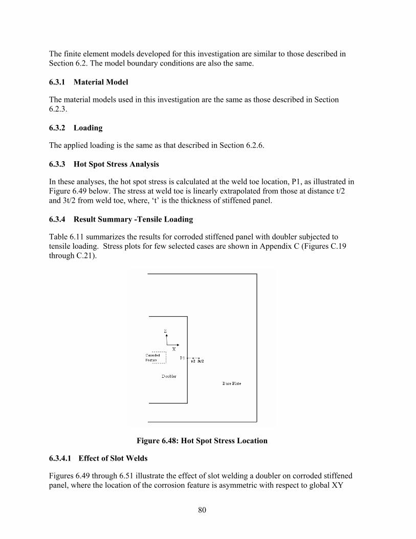
80
The finite element models developed for this investigation are similar to those described in Section 6.2. The model boundary conditions are also the same. 6.3.1 Material Model
The material models used in this investigation are the same as those described in Section 6.2.3. 6.3.2 Loading
The applied loading is the same as that described in Section 6.2.6. 6.3.3 Hot Spot Stress Analysis
In these analyses, the hot spot stress is calculated at the weld toe location, P1, as illustrated in Figure 6.49 below. The stress at weld toe is linearly extrapolated from those at distance t/2 and 3t/2 from weld toe, where, ‘t’ is the thickness of stiffened panel. 6.3.4 Result Summary -Tensile Loading
Table 6.11 summarizes the results for corroded stiffened panel with doubler subjected to tensile loading. Stress plots for few selected cases are shown in Appendix C (Figures C.19 through C.21).
Figure 6.48: Hot Spot Stress Location
6.3.4.1 Effect of Slot Welds
Figures 6.49 through 6.51 illustrate the effect of slot welding a doubler on corroded stiffened panel, where the location of the corrosion feature is asymmetric with respect to global XY

81
plane. For a constant doubler edge distance, as the corrosion aspect ratio increases, slot welding the doubler plate has a greater effect as it lowers the hot spot stress levels.
Dt = 12.7 mm, CW = 152.4 mm, Ct = 9.525 mm, Doubler to corrosion edge distance = 50.8 mm
50
100
150
0 0.5 1 1.5 2 2.5 3 3.5 4 4.5
Corrosion Aspect Ratio (CL/CW)
Hot
Spo
t Str
ess 'σ x
', M
Pa
0(no slot weld)0(with slot weld)w/2(no slot weld)w/2(with slot weld)
Distance from corrosion center to stiffener
Figure 6.49: Effect of Slot Welds @ Dt = 12.7 mm and CW = 152.4 mm

82
Table 6.11: Tensile Loading Summary
Corroded Feature, mm
Distance from Corrosion center to stiffener
Size of Slot Weld, mm Hot Spot
Stress, 'σX' Case
No.
Doubler Thickness,
mm Dt Thick
Ct Width
CW Length
CL mm
Slot Weld
Length Width Pitch MPa
1 12.7 9.525 152 76 0 NO - - - 109.2
2 12.7 9.525 152 152 0 NO - - - 115.6
3 12.7 9.525 152 610 0 NO - - - 125.3
4 9.525 9.525 457 229 0 NO - - - 116.3
5 9.525 9.525 457 457 0 NO - - - 124.2
6 9.525 9.525 457 1829 0 NO - - - 127.7
7 6.35 9.525 762 381 0 NO - - - 111.1
8 6.35 9.525 762 762 0 NO - - - 115.6
9 6.35 9.525 762 3048 0 NO - - - 104.6
10 12.7 9.525 152 76 76.2 NO - - - 115.3
11 12.7 9.525 152 152 76.2 NO - - - 123.1
12 12.7 9.525 152 610 76.2 NO - - - 134.7
13 9.525 9.525 457 229 228.6 NO - - - 96.2
14 9.525 9.525 457 457 228.6 NO - - - 105.0
15 9.525 9.525 457 1829 228.6 NO - - - 113.3
16 6.35 9.525 762 381 381 NO - - - 92.1
17 6.35 9.525 762 762 381 NO - - - 98.4
18 6.35 9.525 762 3048 381 NO - - - 103.5
19 12.7 9.525 152 76 0 YES 76.2 25.4 152.4 108.7
20 12.7 9.525 152 152 0 YES 76.2 25.4 152.4 113.6
21 12.7 9.525 152 610 0 YES 76.2 25.4 152.4 122.7
22 9.525 9.525 457 229 0 YES 76.2 19.05 152.4 113.7
23 9.525 9.525 457 457 0 YES 76.2 19.05 152.4 116.6
24 9.525 9.525 457 1829 0 YES 76.2 19.05 152.4 121.3
25 6.35 9.525 762 381 0 YES 76.2 12.7 152.4 108.9
26 6.35 9.525 762 762 0 YES 76.2 12.7 152.4 112.2
27 6.35 9.525 762 3048 0 YES 76.2 12.7 152.4 103.9
28 12.7 9.525 152 76 76.2 YES 76.2 25.4 152.4 113.9
29 12.7 9.525 152 152 76.2 YES 76.2 25.4 152.4 120.3
30 12.7 9.525 152 610 76.2 YES 76.2 25.4 152.4 129.8
31 9.525 9.525 457 229 228.6 YES 76.2 19.05 152.4 97.6
32 9.525 9.525 457 457 228.6 YES 76.2 19.05 152.4 105.5
33 9.525 9.525 457 1829 228.6 YES 76.2 19.05 152.4 110.5
34 6.35 9.525 762 381 381 YES 76.2 12.7 152.4 92.9
35 6.35 9.525 762 762 381 YES 76.2 12.7 152.4 98.0
36 6.35 9.525 762 3048 381 YES 76.2 12.7 152.4 100.5

83
Dt = 9.525 mm, CW = 457.2 mm, Ct = 9.525 mm, Doubler to corrosion edge distance = 50.8 mm
50
100
150
0 0.5 1 1.5 2 2.5 3 3.5 4 4.5
Corrosion Aspect Ratio (CL/CW)
Hot
Spo
t Str
ess 'σ x
', M
Pa
0(no slot weld)
0(with slot weld)
w/2(no slot weld)
w/2(with slot weld)
Distance from corrosion center to stiffener
Figure 6.50: Effect of Slot Welds @ Dt = 9.525 mm and CW = 457.2 mm
Dt= 6.35 mm, CW = 762 mm, Ct = 9.525 mm, Doubler to corrosion edge distance = 50.8 mm
50
100
150
0 0.5 1 1.5 2 2.5 3 3.5 4 4.5
Corrosion Aspect Ratio (CL/CW)
Hot
Spo
t Str
ess 'σ x
', M
Pa
0(no slot weld)
0(with slot weld)
w/2(no slot weld)
w/2(with slot weld)
Distance from corrosion center to stiffener
Figure 6.51: Effect of Slot Welds @ Dt = 6.35 mm and CW = 762 mm

84
It is also clear from the figures above that the slot welds applied along the stiffener are more effective in reducing hot spot stress levels compared to slot welds applied at a distance of Cw/2 from the stiffener, where Cw is the width of the corrosion feature. 6.3.4.2 Conclusion
Based upon the analyses completed and the results that were generated, the following recommendations for maximizing the fatigue life of a doubler applied to a stiffened panel are presented:
• Slot welding the doubler, strengthens the corroded stiffened panel. The location of corroded feature with respect to stiffener affects the strength of the stiffened panel.
• The larger the corrosion aspect ratio the more significant the effect of slot welds becomes.
• Slot welds are most effective if they are applied along the tops of the stiffener.
6.3.5 Result Summary - Lateral Loading
Table 6.12 summarizes the results for corroded stiffened panel with doubler subjected to lateral loading.

85
Table 6.12: Lateral Loading Summary
Corroded Feature, mm
Distance from Corrosion center to stiffener
Size of Slot Weld, mm Hot Spot
Stress, 'σX' Case
No.
Doubler Thickness,
mm Dt
Thick Ct
Width CW
Length CL
mm
Slot Weld
Length Width Pitch MPa
1 12.7 9.525 152 76 0 NO - - - 39.8
2 12.7 9.525 152 152 0 NO - - - 43.6
3 12.7 9.525 152 610 0 NO - - - 50.1
4 9.525 9.525 457 229 0 NO - - - 41.2
5 9.525 9.525 457 457 0 NO - - - 45.2
6 9.525 9.525 457 1829 0 NO - - - 43.4
7 6.35 9.525 762 381 0 NO - - - 39.6
8 6.35 9.525 762 762 0 NO - - - 41.6
9 6.35 9.525 762 3048 0 NO - - - 24.1
10 12.7 9.525 152 76 76.2 NO - - - 41.7
11 12.7 9.525 152 152 76.2 NO - - - 46.1
12 12.7 9.525 152 610 76.2 NO - - - 53.1
13 9.525 9.525 457 229 228.6 NO - - - 32.6
14 9.525 9.525 457 457 228.6 NO - - - 35.7
15 9.525 9.525 457 1829 228.6 NO - - - 31.7
16 6.35 9.525 762 381 381 NO - - - 32.1
17 6.35 9.525 762 762 381 NO - - - 30.8
18 6.35 9.525 762 3048 381 NO - - - 16.4
19 12.7 9.525 152 76 0 YES 76.2 25.4 152.4 39.5
20 12.7 9.525 152 152 0 YES 76.2 25.4 152.4 43.1
21 12.7 9.525 152 610 0 YES 76.2 25.4 152.4 50.1
22 9.525 9.525 457 229 0 YES 76.2 19.05 152.4 40.4
23 9.525 9.525 457 457 0 YES 76.2 19.05 152.4 42.8
24 9.525 9.525 457 1829 0 YES 76.2 19.05 152.4 42.6
25 6.35 9.525 762 381 0 YES 76.2 12.7 152.4 38.4
26 6.35 9.525 762 762 0 YES 76.2 12.7 152.4 39.9
27 6.35 9.525 762 3048 0 YES 76.2 12.7 152.4 23.8
28 12.7 9.525 152 76 76.2 YES 76.2 25.4 152.4 41.4
29 12.7 9.525 152 152 76.2 YES 76.2 25.4 152.4 45.4
30 12.7 9.525 152 610 76.2 YES 76.2 25.4 152.4 52.0
31 9.525 9.525 457 229 228.6 YES 76.2 19.05 152.4 33.0
32 9.525 9.525 457 457 228.6 YES 76.2 19.05 152.4 35.9
33 9.525 9.525 457 1829 228.6 YES 76.2 19.05 152.4 31.9
34 6.35 9.525 762 381 381 YES 76.2 12.7 152.4 32.6
35 6.35 9.525 762 762 381 YES 76.2 12.7 152.4 31.1
36 6.35 9.525 762 3048 381 YES 76.2 12.7 152.4 15.1

86
6.3.5.1 Effect of Slot Welds
Figures 6.52 through 6.54 illustrate the effect of slot welding a doubler on corroded stiffened panel, where the location of the corrosion feature is asymmetric with respect to global XY plane.
Dt = 12.7 mm, CW = 152.4 mm, Ct = 9.525 mm, Doubler to corrosion edge distance = 50.8 mm
10
20
30
40
50
60
0 0.5 1 1.5 2 2.5 3 3.5 4 4.5
Corrosion Aspect Ratio
Hot
Spo
t Str
ess 'σ x
', M
Pa
0(no slot weld)0(with slot weld)w/2(no slot weld)w/2(with slot weld)
Distance from corrosion center to stiffener
Figure 6.52: Effect of Slot Welds @ Dt = 12.7 mm and CW = 152.4 mm
Figures 6.52 and 6.53 illustrate that for doubler plates with thickness more than 75% of the base plate, slot welding the doubler plate along the stiffener (Figure 6.46) enhances the strength of corroded panel. For scenarios where the edge of corroded feature is aligned with the stiffener (Figure 6.47), slot welding the doubler plate is not very effective. However, when the double plate thickness is around half the thickness of the base plate, slot welding doubler plates does not seem to provide any significant stress reduction (Figure 6.54). Increasing the number of rows of slot weld along the width of doubler would lower weld toe stress, however, this would develop an increased number of fatigue crack initiation sites.

87
Dt = 9.525 mm, CW = 457.2 mm, Ct = 9.525 mm, Doubler to corrosion edge distance = 50.8 mm
10
20
30
40
50
60
0 0.5 1 1.5 2 2.5 3 3.5 4 4.5
Corrosion Aspect Ratio
Hot
Spo
t Str
ess 'σ x
', M
Pa
0(no slot weld)0(with slot weld)w/2(no slot weld)w/2(with slot weld)
Distance from corrosion center to stiffener
Figure 6.53: Effect of Slot Welds @ Dt = 9.525 mm and CW = 457.2 mm
Dt = 6.35 mm, CW = 762 mm, Ct = 9.525 mm, Doubler to corrosion edge distance = 50.8 mm
10
20
30
40
50
60
0 0.5 1 1.5 2 2.5 3 3.5 4 4.5
Corrosion Aspect Ratio
Hot
Spo
t Str
ess 'σ x
', M
Pa
0(no slot weld)0(with slot weld)w/2(no slot weld)w/2(with slot weld)
Distance from corrosion center to stiffener
Figure 6.54: Effect of Slot Welds @ Dt = 6.35 mm and CW = 762 mm

88
6.3.5.2 Conclusion
Based upon the analyses completed and the results that were generated, the following recommendations for maximizing the fatigue life of a doubler applied to a stiffened panel are presented:
• Slot welding the doubler, strengthens the corroded stiffened panel. The location of corroded feature with respect to stiffener affects the strength of the stiffened panel.
• Increasing the number of rows of slot weld along doubler width would strengthen the corroded stiffened panel; however this increase in the number of slot welds would also introduce a great number of potential crack initiation sites.
• For doubler size and thickness, recommendations from Section 6.2 should be followed.
6.3.6 Combined Loading Effect (Tension + Lateral)
For a linear analysis the lateral and tensile applied loading can theoretically be combined by superposition. The application of combined loading would represent the worst-case scenario. Tables 6.13 through 6.15 summarize the hot spot stress results for combined loading for load cases from Table 6.11 and 6.12. The following notations are used in these tables: • 0, and CW/2: Distance between Corrosion Center and Stiffener • NS: No slot weld • WS: With slot weld
Table 6.13: Hot Spot Stress (MPa) @ Dt = 12.7 mm; CW = 152.4 mm
Corrosion Aspect Ratio Combined Hot Spot Stress 'σX', MPa
0- NS 0-WS CW/2-NS CW/2-WS 0.5 149 148 157 155 1 159 157 169 166 4 175 173 188 182
Table 6.14: Hot Spot Stress (MPa) @ Dt = 9.525 mm; CW = 457.2 mm
Corrosion Aspect Ratio Combined Hot Spot Stress 'σX', MPa
0- NS 0-WS CW/2-NS CW/2-WS 0.5 158 154 129 131 1 169 159 141 141 4 171 164 145 142

89
Table 6.15: Hot Spot Stress (MPa) @ Dt = 6.35 mm; CW = 762 mm
Corrosion Aspect Ratio Combined Hot Spot Stress 'σX', MPa
0- NS 0-WS CW/2-NS CW/2-WS 0.5 151 147 124 125 1 157 152 129 129 4 129 128 120 116
Figures 6.55 through 6.57 illustrate the effect of combined loading on hot spot stress for change in corrosion location and slot welding the doubler. The effect of slot welding the doubler is more pronounced as the corrosion aspect ratio increases.
Dt = 12.7 mm; Ct = 9.525 mm; CW = 152.4 mm; Doubler to corrosion edge distance = 50.8 mm
100
120
140
160
180
200
0 1 2 3 4 5
Corrosion Aspect Ratio
Com
bine
d H
ot S
pot S
tres
s 'σ x
', M
Pa
0- NS0-WSCW/2-NSCW/2-WS
Distance from Corrosion Center
to Stiffener
Figure 6.55: Effect of Combined Loading @ Dt = 12.7 mm and CW = 152.4 mm

90
Dt = 9.525 mm; Ct = 9.525 mm; CW = 457.2 mm; Doubler to corrosion edge distance = 50.8 mm
100
120
140
160
180
200
0 1 2 3 4 5
Corrosion Aspect Ratio
Com
bine
d H
ot S
pot S
tres
s 'σ x
', M
Pa
0- NS0-WSCW/2-NSCW/2-WS
Distance from Corrosion Center
to Stiffener
Figure 6.56: Effect of Combined Loading @ Dt = 9.525 mm and CW = 457.2 mm
Dt = 6.35 mm; Ct = 9.525 mm; CW = 762 mm; Doubler to corrosion edge distance = 50.8 mm
100
120
140
160
180
200
0 1 2 3 4 5
Corrosion Aspect Ratio
Com
bine
d H
ot S
pot S
tres
s 'σ x
', M
Pa
0- NS0-WSCW/2-NSCW/2-WS
Distance from Corrosion Center
to Stiffener
Figure 6.57: Effect of Combined Loading @ Dt = 6.35 mm and CW = 762 mm

91
6.3.7 Recommendations
Based upon the analyses completed and the results that were generated, the following recommendations for maximizing the fatigue life of a doubler applied to a stiffened panel are presented:
• Slot welding on larger doubler plates is recommended for corroded stiffened panel. • Increasing the number of rows of slot weld along doubler width would strengthen the
corroded stiffened panel; however, this increases the number potential fatigue crack initiation sites.
• For doubler size and thickness, recommendations from Section 6.2 should be followed.
6.4 Effect of Residual Stress
In the initial project plan, it was proposed to investigate residual stress effects on fatigue and fracture. In general, higher residual stresses will increase fatigue crack growth rates and the potential for fracture, but not plastic collapse. In completing the project, local stress due to the applied loading was used as a surrogate for fatigue and fracture driving force. The design criteria were developed to ensure that the doubler repair had the same or better performance (yield strength, buckling, fatigue, and fracture resistance) as the original structure. With this approach taken the effect of residual stress is reduced to a secondary effect in which high levels of non-uniformly distributed residual stress could result in distortion that would reduce buckling loads or promote secondary bending that would enhance fatigue crack initiation or growth. For this reason residual stresses were not considered.

92
7.0 CORROSION BEHAVIOR
7.1 Corrosion Considerations for Doubler Plates
An important factor to be considered in the stress analysis of doubler plate repairs is the estimated reduction of material and effects due to corrosion. There are multiple ways in which corrosion can damage structures, in particular with consideration of the more aggressive types of corrosion with localized effects (specifically of the weldment), general wasting or a combination of both.
This section first provides a literature review of related work. This is followed by a discussion of 1) Probabilistic, 2) Deterministic models and 3) Empirical approaches estimating the corrosion behavior of ship structures. Discussion of the mechanisms of corrosion with respect to doubler plates is discussed and a variation of an existing model is used. Correlation of the predicted behavior with a survey of shipyards on doubler plates is presented.
7.2 Literature Review
7.2.1 Ship Structure Committee Reports
Several ship structure committee reports have investigated the behavior of corrosion with respect to fatigue and repair welding issues.
Most recently, Dexter, Fitzpatrick and St. Peter (2003) in SSC-425 investigated fatigue behavior that consisted of tests performed to generate S-N (stress vs. number of cycle to failure) curves for ship structure configurations in areas subject to fatigue. Included in the evaluation were doubler plates used as a repair for cracking. The crack was first repaired and then a doubler was then applied over the repair. The repair geometries were classified for fatigue based on AASHTO S-N curves. The doubler plate repair was categorized as a Class E or E’ repair; considered undesirable in terms of fatigue life. In testing, however the doubler plates exceeded the AASHTO predicted values. The doubler plates were 18mm thickness x 76-102 mm wide and 203-254 mm in length, applied using SMAW with 7018 electrodes.
Jaske (2000) in SSC-412 considered corrosion in investigating the effect of cathodic protection on the fatigue of steel plate in synthetic seawater. The study included corrosion fatigue testing of butt-welded and fillet-welded joints as well as unwelded base metal specimens. It modeled the fatigue cracking occurred as the two stage crack initiation followed by crack propagation. It was reported that fatigue cracking occurred at the toes of the weld and not at the midspan of the specimen. In particular it was found that undercut weld toes had very low fatigue strength. Additionally, it was found that butt welds had higher fatigue resistance than the fillet welds. This report also included a very extensive bibliographic list with summaries.

93
Kirkhope, et al. in SSC-400 (1997) discussed methods to improve the fatigue behavior of weldments and includes protection from corrosion. It recommends weld toe grinding and other treatments to decrease corrosion losses with referenced fatigue studies of weld treatment in seawater and with cathodic protection. In this case configuration is double fillet weld that has bending moment applied. Another method that is recommended for improve corrosion resistance for welds is to hammer peen joints. It references studies that demonstrate that hammer peened welds reduce losses in both free corrosion and cathodic protection conditions.
Parente, Daidola, Basar and Rodi (1997), in SSC-397, provide a discussion of general corrosion protection for shipbuilding and maintenance. This includes a discussion of welding considerations to include avoidance of intermittent welds and lap joints due to concern for crevice corrosion. Consideration of joining techniques and the importance of proper welding specification is emphasized. Although corrosion rates are not quantified, the report makes general recommendations for corrosion behavior including welded joints.
Reynolds and Todd (1992) in SSC-366, conducted testing on HSLA welded steel for evaluation of corrosion fatigue in the Parent Metal (PM), Heat Affected Zone (HAZ) and Weld Metal (WM) regions and determined threshold stress levels for corrosion fatigue behavior.
Daidola and Parente (1996) SSC-394, detail corrosion behavior (specifically, pitting) of plates for ship structures. It was observed that pitting corrosion may occur preferentially at weld seams and butts and it is stated that the welds typically corrode 3-5 mm more than the surrounding plate in these areas. Two models are used to estimate the loss of plate thickness due to pitting.
Stambaugh and Knecht (1988) in SSC-348 provided an overview of corrosion behavior and data from ship structures. The corrosion behavior is categorized into eight classifications of corrosion as 1.General (Uniform), 2. Galvanic, 3. Crevice, 4. Pitting / Grooving, 5. Intergranular, 6.Selective Leaching, 7. Velocity Corrosion, and 8. Stress Corrosion Cracking. It discussed locations and conditions in which particular corrosion behavior occurred including mention of localized corrosion in the area of welds. A general overview of the methods for determination of corrosion rates was discussed.
Burnside, et al. (1984) in SSC-326 investigated corrosion fatigue to include consideration of weldments. The report determined the fatigue loading and then characterized fatigue cracking based on the stress condition with consideration of several variables to determine a crack growth rate for fatigue. Welded joints were specifically considered using a local strain approach. Analytical and experiment results were determined in air and in seawater. Corrosion fatigue of welded joints to include specifically addressing the sensitivity of weld toe geometry and local stress factors is detailed. A probabilistic model was used to characterize corrosion fatigue behavior.

94
Krumpton and Jordan, (1983) in SSC-323 considered geometry of fillet welds for ship structures, analyzes the stress state and makes recommendations. The focus was on ABS rules for welding although Navy welding requirements were also discussed. Included in the analysis is consideration of uniform corrosion of a weld to include a corrosion allowance. Intermittent welds were discussed separately to include a corrosion allowance for uniform corrosion.
7.3 Additional Investigations: Probabilistic and Deterministic Approaches
The most recent investigation on predicting corrosion and fatigue behavior for ship structures are summarized. These are primarily probabilistic approaches that are appropriate for characterizing large sets of data that have may have multiple variables. These studies have as a basis, a large field database of vessels in which the corrosion loss data may be subdivided into categories of particular locations and service conditions. As expected, this data has significant variability, but is useful in risk assessment conditions. By contrast, a deterministic approach may be used for a specific mechanism (for example, pitting). This type of approach is appropriate to quantify behavior if the particular corrosion mechanism is identified.
Wang, Spenser and Elsayed (2003a) used a probabilistic approach for a large database of approximately 110,000 thickness measurements in varied locations from 140 oil tankers (single hull). The paper lists factors for corrosion in oil tankers to include Coating Type and Longevity, Coating Application and Surface Preparation, Corrosivity of the Product, Inspection and Maintenance Strategies, Cathodic Protection, Trade Route, and others. Wang contrasts the three approaches for the analysis of corrosion rates is given as 1. Probabilistic representations, 2. Corrosion rate models, 3. Corrosion wastage databases. Wang recommends the probabilistic approach due to the variability of the data. Presented are corrosion rates for different locations with the mean, maximum and standard deviation. The results were compared with prior results from the TSCF (Tanker Structure Cooperative Forum) in the higher range of the results.
In Wang, Spenser and Sun (2003b), the database from the tanker study was used for the assessment of corrosion rates for aging ships. The corrosion wastage is ranked by three levels: slight, moderate, and severe levels corresponding to 50, 75 and 95% cumulative probability on the database which is thickness measurements taken by ABS (110000 on 140 oil tankers). It recommends a reliability based approach to model the uncertainties probabilistically vs. traditional engineering approaches which used deterministic approaches for a time variant process. It was found that the corrosion wastage had very high variability but that it exhibited an increasing trend in rate with the passage of time, i.e. the corrosion rate increased for aged ships.
Several studies have been conducted by Paik, et al. (2004(a), 2004(b), 2003(a), 2003(b), 1998(a), 1998(b), 1997) on corrosion analysis in several areas of ship structures.

95
Paik, et al. (2003a) formulated a mathematical model for time variant corrosion wastage of ship structures. This was used with statistical data of for both single and double hulled tankers and for FSOs (Floating Storage and Offshore loading units) and FPSOs (Floating Production, Storage, and Offshore loading units). The corrosion model additionally grouped structural members by type and location. The types of corrosion wastage typical to ship structures were identified as (a) general corrosion, (b) localized corrosion and (c) fatigue cracking from localized corrosion. The localized corrosion patterns typical to ship structures were identified as 1) Pitting, which typically occurs on bottom plating and at details that trap water and in particular aft tanks were identified 2) Grooving, described as “in line” pitting and 3) Weld Metal Corrosion, postulated as by galvanic action and initially characterized by pitting. The corrosion is modeled successively into three phases: 1) No corrosion while coating is intact, 2) Transition to Corrosion, and 3) Corrosion Progression. In the case of the Corrosion Progression stage, the time-dependent corrosion could be modeled as convex (decelerating with time) or as concave upward (accelerating with time). The depth of corrosion (tr) was expressed as tr = C1(T-Tc-Tt)C2 = C1Te
C2 , in which T= Structure Age, Tc = Time of Coating Durability, Tt =Transition Time and Te = Time of Exposure under corrosion environment. The annualized corrosion rate (rr) was defined as rr = C1 C2Te
C2-1. The constant C1 is indicative of the annual corrosion rate and C2 characterizes determines the trend of the corrosion process. The progress of corrosion stage is characterized by the mechanism of corrosion; which would be convex downward, for example for immersion general corrosion (due to scale formation). A concave upward curve represents increased corrosion which may be more applicable to dynamic conditions. The coating life variable Tc was fixed as 5, 7.5 and 10 years until breakdown, the coefficient C2 was set equal to 1 for linear corrosion and C1 was found by fitting statistical data for particular groupings, ship structure type and coating lifetimes. Included as conclusions from the study, was that the annualized corrosion rates followed a Weibull distribution, and that the rates differed for the different location/category groups. The range of most probable corrosion rates was from approximately .026 mm/year to .24 mm/year, but that the most severe corrosion rates could be several times higher.
In Paik, Wang, Thayamballi and Lee (2003b), the effect corrosion included both uniform corrosion as well as non-uniform pitting behavior in the investigation of aging ships. A DOP (degree of pitting) parameter characterized loss due to pitting of a plate. A time dependent corrosion model was detailed in which the behavior of was again characterized in three stages: 1) durability of coating, 2) transition stage and 3) progress of corrosion phase. Statistical analysis using the Weibull distribution with the mean value and COV are established. Fatigue behavior is also characterized. Reliability analysis for each, a bulk carrier, ship type FPSO and double walled tanker is preformed under multiple damage scenarios to ultimate longitudinal strength failure. The five damage scenarios used in the assessment included: 1) undamaged, 2) corrosion 3) corrosion + local dent damage, 4) corrosion + fatigue cracking, 5) corrosion + fatigue cracking + local dent damage for time dependent risk assessment of ships. Paik (2004b) and Paik, Kim and Lee (2004b) were investigations of corrosion behavior of ballast tanks. Corrosion behavior was again modeled as initiating after the coating breakdown takes place which is varied at 5, 7.5 and 10 years. The corrosion depth formula

96
was used as tr = C1(T-Tc). The annual corrosion rate was linear as rr = C1. The mean value of parameter C1 and the COV (coefficient of variation) were found for a Weibull statistical analysis. Results were summarized with C1 and COV determined using a database of over 1900 data sets for the ballast tanks of bulk carriers and oil tankers. The results were then summarized and corrosions margins offered with sample calculations for each a representative bulk carrier and tanker.
Moan, Ayala-Uraga and Wang (2004) used a reliability method in evaluating FPSO structures formulation that includes fatigue and corrosion. The effect of corrosion on fatigue failure used a time dependent corrosion wastage was defined as W(t) = Rcorr · α(t-To) in which α is 1 in this case since the corrosion considered was one sided (α =2 for corrosion on both sides), To as the time for the corrosion protection system breakdown and Rcorr as the annual wastage rate. The combination of corrosion wastage and fracture cracking was treated using a fracture mechanics model. A reliability model using the probability of failure based on crack growth is utilized to include corrosion modeled using a Weibull distribution analysis. The analysis also included consideration of the reliability level based on inspection for fatigue cracks and thickness measurements.
Guedes Soares and Gorbtov (1999a) used a reliability analysis for fatigue cracking, corrosion and their interaction with respect to failure of longitudinal members. It modeled fatigue cracking at joints of the midship section as well as corrosion of each plate in the midship section. From the classic Paris-Erdogan crack propagation equation da/dN = C∆Km, in which a= crack length, N=number of stress cycles, ∆K= stress intensification factor and C is constant, a model is developed using a statistical treatment for fatigue stress with consideration of corrosion. In the corrosion analysis, the difference between general corrosion resulting in loss of plate thickness as well the more complicated behavior of pitting for localized perforation is addressed. It notes that the corrosion behavior is dependent on the protection system and separates the behavior into the two stages of 1.) Time of Coating Effectiveness followed by, 2.) Coating Effectiveness is lost and general corrosion occurs which was represented linearly as wastage. A Weibull distribution was used for reliability analysis for this time variant study which also included the effect of repair operations.
Guedes Soares and Gorbtov (1999b) provided a non-linear model of corrosion behavior of plates. It was stated that the two main corrosion mechanisms for plates are by general wastage and by pitting. The pitting of plates was not considered due to its localized nature. The general wastage was considered as non-linear behavior that levels out to a value d∞ = long term thickness loss due to corrosion wastage. The three stages of corrosion wastage were modeled by the general equation d∞ d˙(t) + d(t) = d∞. The particular solution for the depth of corrosion, d, as a function of time (t), is given as d(t) = 0 for t >τc , i.e. there is no corrosion during the time that the coating is effective (τc). This is followed by the solution of the depth of corrosion of d(t) =d∞(1- e-(t-τc/τt)) for t ≤τc , after the coating is no longer effective during the transition time stage τt , followed by the time of corrosion stage, τc . The corrosion model was tested using data from Paik, et al. (1998b). The corrosion loss was then incorporated into a reliability analysis for failure of the plate in compression to include decreased strength due to the loss of material due to corrosion.

97
Garbatov, Rudan and Guedes Soares (2002), used the above non-linear approximation for wastage to study fatigue damage with corrosion for knuckle joint and a bracket with a high stress concentration effect. The non-linear corrosion loss was used with the DNV formulations (1998a) for damage due to fatigue with consideration of corrosion based on a percentage loss in a corrosion environment.
Melchers (1999a) described a non-linear empirical model for general wastage of steel under immersion conditions using dw = .084t.823, in which dw = uniform corrosion depth and t is the time of immersion. He has proposed a phenomenological model to consider each regime of corrosion using a probabilistic form of c(t,E) = fn(t,E) + ε(t,E), in which c(t,E) = weight loss function, fn(t,E) = mean value function, ε(t,E) = mean value function, t=time and E=environmental condition vector. The factors that affect corrosion behavior are also discussed to include, but not limited to, temperature, oxygen content, marine growth and water velocity. Melchers had designated the stages of marine corrosion are given as an initial kinetic controlled anodic behavior, followed by diffusion controlled behavior and the last stage is anaerobic controlled behavior. In Melchers (1999(b)), the large uncertainty in modeling corrosion behavior is discussed and he advocates for more extensive fundamental investigation of marine corrosion specifically. Southwell (1979) provided a linear and bilinear model for general wastage due to immersion in seawater loss (mm) as a bilinear model of d= .090t for 0.00≤ t< 1.46 and d = .076+.038t for 1.46≤ t< 16 for higher temperature water in which d= depth of corrosion and t = time in years. The steel used was 1020 plain carbon steel and various conditions were addressed in the study that was conducted over a sixteen year study. The primary reason for having two regions in this case was due to the change in corrosion behavior after a significant fouling was present. Pitting was also analyzed and found to initially have corrosion rates on the order of 5-7 times greater than general wastage for the first two years and later to decrease to approximately 2.5 to 2.7 mils/year (.06-.07 mm/year); similar to the steady state long term general wastage rate. The decrease in the long term rate for pitting was also attributed to fouling.
Marine Corrosion behavior for ship structures is often assumed as linear behavior with a nominal rate of .1 mm/year used for general wastage unless otherwise defined. A summary of equations used for corrosion estimation are listed in Table 7.1.

98
Table 7.1: Summary of Relationships for Corrosion Behavior
Uniform Linear Corrosion Rate (Wastage)
d = Ct
d = depth of corrosion (mm or inch)
C = corrosion rate (mm/yr), or mils/year (mil=10-
3inch) t = time
Southwell(1979) Bilinear Model of steel immersed in seawater.
d = .090t 0.00≤ t< 1.46 d = .076+.038t 1.46≤ t< 16.
d = depth of corrosion (mm) t = time (year)
Kondo (1989) Pitting Corrosion Growth in a Fatigue Environment
c =Cp(N/f)1/3 2ccr = (2Q/πα)[(∆K)p/2.24σa]2
c = pit radius a = depth of pit α = a/c aspect ratio N = number of cycles f = frequency Cp= Coefficient Q = shape factor 2ccr = critical pit diameter σa = stress amplitude (∆K)p = stress intensity factor
Daidola(1996) Pitting of Plate Panels in Ship Structures
∆t = V/A
N
V = c· Σ ( (π/4) wi2· di))
i =1
∆t = thickness reduction due to Pitting V = Wasted Steel Volume A = Area of Plate c = .667 for semi-spherical pits w = pit width d = pit depth
Melchers(1999) Empirical Model
dw = .084t.823
dw = Depth of Corrosion Wastage t = time
Guedes Soares & Garbatov (1999b) Non-linear model with Three Stages of Corrosion Behavior
General Equation: d∞ d˙(t) + d(t) = d∞. Solution: d(t) = 0 for t >τc d(t) =d∞(1- e-(t-τc/τt)) for t ≤τc
d = depth of corrosion d∞ = long term thickness
loss due to corrosion τc= time that the coating is
effective τt = time of transition τc = time of corrosion stage t = time
Paik (2003) Non-linear model with Three Stages of Corrosion
1) tr = C1(T-Tc-Tt)C2 = C1Te
C2 rr = annualized corrosion rate T = Structure Age

99
Behavior 2) rr = C1 C2TeC2-1
Tc = Time of Coating Durability Tt = Transition Time and Te = Time of Exposure C1 = constant (indicates
annual corrosion rate) C2 = constant (indicates
corrosion process trend)
tr = depth of corrosion Moan(2004) Two stage linear corrosion model
W(t) = Rcorr · α(t-To)
W(t) = corrosion wastage α = number of sides exposed
= (1 or 2) To = time to corrosion
protection system breakdown
Rcorr = the annual wastage rate. t = time
The three stage model for corrosion behavior is shown in Figure 7.1 below. The first Stage I is the time until the corrosion protection breakdown, followed by Stage II as a transitional stage, and finally stage III (long term steady state) corrosion.
Figure 7.1: Corrosion Behavior as Three Stages
Corrosion Loss in Three Stages
Time
Dep
th o
f C
orro
sion
I IIII

100
0
0.5
1
1.5
2
2.5
3
3.5
4
0 5 10 15 20 25 30
t=Exposure Time (years)
Corr
osio
n Lo
ss (m
m)
LINEAR (Uniform Wastage)INCREASING (Local Corrosion)DECREASING (Static Immersion)
Figure 7.2: Long Term (Stage III) Corrosion Behavior
A comparison of the formulations is shown in Figure 7.2. The graphs shown are for 1) linear behavior of .1mm/yr, 2) decreasing rate that is typical of static immersion, in this case shown using the Melchers equation and 3) increasing rate, using the Paik equation with a coefficient of C2> 1.
7.4 Corrosion Considerations for Welded Doubler Plates
7.4.1 Mechanisms of Corrosion at Welded Doubler Plates
Corrosion in the area of a welded doubler plate does not have the same mechanisms as that of the base plate material. A primary consideration in corrosion behavior of doubler plates is at the weld and the adjacent HAZ (heat affected zone). The variables associated with the high local corrosion in the area at the weldment is due to the metallurgical differences as well as the higher stresses present. Also, as corrosion occurs, it results in the loss of material and magnitude of stress increases over time. In the case of a doubler repair, the presence of defects and the potential for crevice corrosion as well as pitting are also of concern. The presence of defects includes existing defects as well as cracking due to fatigue is this area. General wastage of the plate should be considered, however the more severe corrosion mechanisms should govern in estimating corrosion loss. The various mechanisms of corrosion of welds are overviewed by Griffiths and Turnbull (1999), in addition to detailing various methodologies for testing. Variables that affect corrosion behavior are listed in Table 7.2.

101
Table 7.2: Variables of Corrosion Behavior
General Factors Affecting Corrosion Behavior in Marine Environment Total Immersion vs. Atmospheric or Alternating Wet/Dry Environment Seawater chemistry Oxygen content Temperature Velocity Parent Alloy Corrosion Protection: Coating / Cathodic Protection System MIC (Microbial Induced Corrosion)
Additional Corrosion Considerations at Doubler Plate Location of Doubler Plate Fatigue Loading Stress Concentration Geometry Profile of Doubler Presence of Residual Stresses at Weldment Presence of Weld Defects Intermittent Welding vs. Continuous Welding Welding Process/Filler Metal /Procedure Used Galvanic Corrosion due to Microstructural Differences at Weldment Localized Corrosion Behavior: Pitting / Grooving / Crevice Corrosion
The higher stresses at the doubler plate due to geometric stress concentration are detailed in the prior sections of this report as being highest at the weld toe. Additional stress concentration occurs in the area of weld defects. Residual stresses are also present due to welding. The welding process and geometry determines the magnitude and type of residual stresses present. These residual stresses exist as a result of constrained thermal expansion/ contraction due to the very large temperature differential of the welding process, as well as by the microstructural changes that occur. The microstructural changes may include multiple phases that are not present in the base plate as well as an altered grain structure. The resultant microstructure and residual stress due to welding are determined by the weld process, heat input, welding speed, weld sequence, joint geometry, heat transferability, and filler metal. Detail of weld metallurgy is by Linnert (1965) and Masubuchi (1980) The effect of defects present on corrosion and fatigue was discussed in El-Gammal (2003) in the context of a fitness of service approach to optimize fabrication methods. Paik (2003a) also noted that the weld metal corrosion for ship structures was more prevalent for hand welds than for machine welds. This is associated with the more variable quality of hand welding to include more non uniformity and ridges that provide future sites for initiation of

102
corrosion and fatigue behavior. It can be assumed that there may also be a greater presence of weld defects. This observation is important in the consideration of doubler plates, since the welding performed by hand.
Sephon and Pistorius (2000) discuss the specific mechanisms of corrosion of carbon steel weldments tested in flowing 3.5% NaCl. Corrosion rates were determined using electrochemical methods. The difference in potential (mV) was found for different microstructures. It was reported that this galvanic difference between the microstructures was initially the significant corrosion mechanism until steady state conditions were reached. The most significant long term corrosion loss was found at the fusion line of the weld as grooving. The grooves were characterized to consist of a multitude of pits of various depths that appeared to coalesce. In this case the localized corrosion was related to defects of network of sulfide inclusions along grain boundaries. The description of coalesced pitting along the fusion line is consistent with the behavior that has been observed in the corrosion of ship structures in the area of welds having localized pitting / grooving behavior as shown in Stambaugh and Knecht (1988).
Consideration of materials and welding is particularly important in the case of higher strength steels which are susceptible to stress corrosion cracking (SSC) along grain boundaries, particularly in the area of weldments. Additionally, the use of higher strength steel requires less thickness of plate, which results in 1) greater deflection which removes protective scale formation or biofilm, and 2) reduced thickness due to corrosion occurs as a greater percentage of the plate. Additionally, as SSC occurs, the material is embrittled, such that fatigue cracking is accelerated, particularly as the mean stress and stress amplitude is increased. Several studies have discussed the behavior of high strength steels, which is not considered here for doubler plate repairs.
It should be noted that corrosion fatigue is not the same as stress corrosion cracking. Corrosion fatigue is a general condition in that the endurance limit of a metal is lower in a corrosion environment and does not necessarily involve embrittlement. Typically steels have a fatigue limit in air, but do not in an aqueous electrolytic environment. (Talbot, 1998) As the stress is increased, the time until failure is decreased. As the area of a welded repair is at a higher stress level, it is therefore more susceptible to long term fatigue damage. Surface weld defects and pits are also a factor involved with corrosion fatigue in that they provide initiation sites for crack propagation.
Crevice corrosion occurs due to the change in oxygen present in a corrosion environment due to having electrolyte (stagnant seawater) trapped and maintained in a small space. Lapped joints are subject to crevice corrosion which has very accelerated corrosion rates, as the reactivity is high in a small area in which the anodic portion corrodes rapidly. It is key that doublers be watertight to avoid crevice corrosion and also to avoid lack of fusion weld defects.
Pitting has similarities to crevice corrosion in that it is autocatalytic and has high localized rates. Pitting is associated local variations that may become micro-anode / cathodic areas. Mild steels are not susceptible to pitting, however in the case of being in the area of a weld

103
and having stagnant seawater environment, it does occur. An example is that of an internal tank bottom plate which is particularly susceptible to pitting.
A major consideration for the corrosion of doubler plates is the location of the installation. The location is most significant as to whether the doubler repair is for an internal or external location and more importantly if the location environment is in a 1) immersed, 2) atmospheric, or the worst case, 3) an alternating wet / dry condition. For internal repairs exposed to product, the chemistry of the corrosion reaction may be affected, which is not considered here. The location of the doubler also defines the local stress condition. A further consideration is that the doubler plate repair discussed in this report is to repair prior corrosion damage. The doubler plate repair is therefore at a location that has already been established as a higher corrosion environment that has experienced corrosion protection failure. This serves as additional justification to assume higher corrosion rates in this area and that the time of protection/ transition prior to corrosion behavior is minimal. 7.4.2 Shipyard Survey
A survey of shipyards was conducted for this report in 2004 on the methodology and results of doubler plate application. Of thirteen respondent shipyards, there were varied responses on the approach to doubler repairs which impact corrosion behavior over the lifetime of the doubler plate repair. The survey conducted reported various applications of doubler plates at different shipyards. The sizes ranged from 3”diameter to 8’x40’. The weld procedures used included both SMAW “stick” (6011 and 7018 filler rods) and MIG welding techniques, heat treatment was not used (with exception of one shipyard that stated heat treatment was seldom used). Varied locations of doublers were reported to include internal and external applications and above and below the waterline. It was noted by two shipyards that doublers were not used for cargo and fuel tank boundaries (this is not allowed by classification societies due to possible entrapment of flammables). One shipyard commented that the doublers were never used in wet spaces although another respondent used doublers for “wet spaces / internal” locations. The lifetime expectation of the doubler repair varied from until “next docking” to “for life”. The results were evenly divided on the question of lifetime, with six respondents stating that the lifetime expectation was from 10 years to life, four respondents had short life time expectations (<2.5 years) and two shipyards did not respond. Since the majority of respondents have an expectation that the doubler repair should have a significant lifetime, the corrosion loss should be known such that premature failure does not occur.
In considering the results of the shipyard survey, most are consistent with the recommendations of the Repair Standard 47 by IACS (1996) for the installation of doublers, with the exception that some of the repairs are smaller that the standard includes. The minimum size doubler plate per IACS is 300mm x 300 mm (11.8 in x 11.8 in). The thickness of the doubler plates ranged from ¼” to 1 inch. All of the shipyards responded that they provided a radius at the corners of the doubler to reduce stress concentration. A 3”

104
radius was the typical dimension given by the respondents, and all of those providing dimensional information exceeded the IACS recommendation of a minimum radius of R≥50 mm (1.96 inch). The majority of the shipyards used slot welding with size of slots ranging from the width of 1t (thickness of doubler) to 2” diameter (plug) weld, and the length from 1”-3”, with some respondents noting the slot was to be completely filled. The slot sizing of the width was generally smaller that in the IACS dimensions of 2t x (80 – 100) for width by length (mm) respectively. On the use of doubler plates, ten of the shipyard respondents recommended the use of doublers, although two stated that this was for temporary repairs only. Additionally two shipyards did not recommend the use of doubler plates but recommended inserts instead.
Of interest is that two of the shipyards included comments on cracking as 1.) “cracks in parent plates as doubler is applied” and 2.) ‘Sometimes cut ' X ' in plate before welding edges - prevents cracking”. This substantiates the significant increase in local stresses on the application of the doubler plate. There were several comments on the criticality workmanship, that to be effective the doubler must be installed correctly. There were also several positive comments including those on productivity of being low cost and time-savings as well as “never seen one fail”. With the diversity of responses that were given for varied parameters, further guidance on the application of doublers is needed.
7.4.3 Corrosion Behavior of Doubler Plates
As detailed in section 7.4.1, the corrosion behavior in the area of the doubler repair is expected to differ from that of the base plate material and in fact is expected to occur at a higher rate. To quantify the loss due to corrosion in this area, the behavior should be modeled as non-linear behavior that attempts to characterize the particular corrosion mechanism. The approach presented here is to modify a non-linear multiple stage relationship similar to those that have been used on ship structures with coefficients fit to incorporate the higher rate for localized corrosion behavior in the area of the doubler plate.
As detailed it has been seen in several studies that corrosion behavior is not constant, but that it may be generalized into stages. In this case, the three stages approach is used of:
Stage I: tc= time until corrosion protection system failure Stage II: tt= transitional time Stage III: tc= time of long term non-linear corrosion behavior
The equation used is in the form of Paik (2003): d = C1(t)C2 in which the terms are defined as: d= depth of corrosion (mm)

105
C1 = constant (indicator of the corrosion rate) C2 = constant (indicator of the corrosion trend) t = time (year)
For prediction of doubler plate corrosion behavior, the equation is stated as: Stage I : d = C1(t)C2 , C1 = 0 Stage II: d = C1(t-tI)C2 , C1 ≠ 0, C2 = 1 Stage III: d = C1(t-t-tII)C2 , C1 ≠ 0, C2 ≠ 0
In the use of doubler, Stage I is minimized or may be assumed zero, since this is a repair application such that the original corrosion protection system is not intact and, specifically, the application is for an area that has already failed in corrosion. Additionally the vessel is generally an older vessel, which typically has higher rates of corrosion in part because the aging of the protection system.
The stage II is shown linearly as a higher corrosion rate that then levels off in Stage III non-linear long term corrosion. In this case the galvanic mechanism in the area of the weldment is considered as the driver of the increased corrosion rate in the short term Stage II.
The Stage III corrosion is characterized by the non-linear increasing behavior as the long term corrosion is higher than general wastage due to the fact that this is a higher stress area and to include consideration of localized corrosion. Stage III should not be considered linear general wastage and it also in not suitable to have the decreasing trend typical static immersed system. It is assumed that the location under non-static stress conditions therefore and would not be expected to form a protective film. A plot of the predictive model is shown in Figure 7.3 using the following:
Region I = 0 Region II (0 ≤ t < 2.5 years): C1 = .5, C2 = 1 (linear) Region III (t >2.5years): C1 = .05, C2 = 1.03 (increasing)
The selection coefficients for the figure shown are indicative of the general trend to include general wastage with localized corrosion for doubler plates. The actual rate of corrosion is dependent on the location and the service conditions for the application of repair. Due to the variability as indicated in the studies by Paik, Garbatov, Guedes-Soares and Wang, the location of the doubler is key. Corrosion behavior in general and the lack of continuity of the repair methodology does not lend itself to a particular rate. However, to should be recognize that corrosion rate is higher for a doubler and the localized corrosion increases over time. Recommendations to decrease the more severe corrosion mechanisms in the area of doubler plates are made in the next section.

106
0
1
2
3
4
5
6
0 5 10 15 20
Time (years)
dept
h of
cor
rosi
on, d
(mm
)
Figure 7.3: Predictive Corrosion Behavior of Doubler Plate Repair
7.5 Recommendations
Recommendations to extend the life of doubler repairs are given as follows based on the respondent shipyard practices and in consideration with factors that increase the corrosion rates:
It is recommended that shipyards to follow the guidelines in IACS 47 (1996) Repair Standard Section 6.3 on doublers. The exception being for those doubler repairs that are smaller than 12” x 12”, which are not covered by the standard. Use a proper welding sequence (i.e. weld opposite sides instead of adjacent sides) as an insert. This reduces the localized stress and therefore the long term corrosion and corrosion fatigue susceptibility. Using rounded corners to reduce stress concentration with a minimum radius of curvature of 2” - 3” is recommended.
In general, avoid the used of intermittent welds, if possible, to avoid localized corrosion to include crevice corrosion. Intermittent weld should only be used in the case of very large doublers. If intermittent welds are found to be necessary, the slot width should be per the guidelines of a minimum of 2td = twice the doubler plate thickness and the minimum distance of 15td for a slot to the edge of a plate. Presently, some of the respondent shipyards use more narrow slots, which should be avoided.
As doubler plates are applied by hand and may have great variability in the welding technique, the importance of good welding practices cannot be overemphasized. In the case of doubler repairs, defects that present potential for future corrosion and fatigue sites must be eliminated by grinding and in particular, discontinuity in the toe region of the weld should be avoided. Cracking is not acceptable. Table 3.2 of SSC-400 (Kirkhope, et al., 1996) provides an overview of effective techniques for weld improvement to include hammer peening as well as correct weld profile that are applicable for doubler plate application.

107
8.0 DESIGN GUIDELINES FOR DOUBLER PLATE REPAIRS
In sections 5 and 6, finite element analyses were performed to check the effect of different doubler plate design parameters on the buckling strength and fatigue strength of stiffened plate panels, respectively. Several recommendations were made based on these analyses. Each set of recommendations was based on the analysis performed with certain variables. In this section, we combine all of the recommendations made in the sections 5 and 6 and come up with one set of recommendations that satisfies all the requirements. Recommendations for reducing corrosion of welded doubler plates were made in section 7.5. Recommendations made in the previous sections are repeated below for better understanding.
8.1 Doubler Recommendations for Buckling Strength
Based upon the analyses completed and the results that were generated, the following recommendations for restoring the buckling strength of a stiffened plate with a doubler are presented:
• For metal loss greater than 25% of parent plate thickness, the use of doublers is not recommended.
• To restore the buckling resistance of a stiffened panel, the doubler plate thickness should be greater than the larger of:
o 65% of the original stiffened panel plate thickness (Dt > 0.65*Bt) o thickness required by the doubler thickness factor of 2.6 (i.e. 2.6*(Bt - Ct))
• The doubler size (length and width), and doubler plate edge distance can be any value but care should be taken to minimize the size of the doubler plate. It is recommended that a 50mm (2 inch) corrosion feature to doubler edge distance be used. It is noted that larger doubler plates will need slot welds to ensure stability.
8.2 Doubler Recommendations for Fatigue Strength
8.2.1 Recommendations for Doubler Corner Radius
Based upon the results, a simple linear regression was performed to obtain a relationship between doubler corner radius (DR), doubler plate thickness (Dt) and base plate thickness (Bt). This relationship is shown below: DR = 82.4*(Dt / Bt) + 2.46 where R has units of mm. This equation may be used to define the most appropriate doubler corner radius for a range of plate thicknesses.

108
8.2.2 Recommendations for Doubler to Base Plate Thickness Ratio
Based upon the analyses completed and the results that were generated, the following recommendations for maximizing the fatigue life of a doubler applied to a stiffened panel are presented:
• Doubler, Dt , thickness should always be greater than 0.5*Bt • Doubler thicknesses, should be as large as reasonable • Doubler to corrosion edge distance should be kept as small as possible and certainly
be less than 100 mm
8.2.3 Recommendations for Slot Welds
Based upon the analyses completed and the results that were generated, the following recommendations for maximizing the fatigue life of a doubler applied to a stiffened panel are presented:
• Slot welding on large doubler plates is recommended for corroded stiffened panel. • Increasing the number of rows of slot weld along doubler width would strengthen the
corroded stiffened panel; however, this increases the number potential fatigue crack initiation sites.
• For doubler size and thickness, recommendations from Section 8.2.2 should be followed.
The IACS Guidelines for Temporary Doubler Plate Installation shown in Figure 3.1 is repeated in Figure 8.1.
8.3 Recommendations for Reducing Corrosion
Recommendations to extend the life of doubler repairs are given in section 7.5 and reproduced below.
• It is recommended that shipyards follow the guidelines in IACS 47 (1996) Repair
Standard Section 6.3 on doublers. The exception being for those doubler repairs that are smaller than 12” x 12”, which are not covered by the standard.
• For insert plates use a proper welding sequence (i.e. weld opposite sides instead of
adjacent sides). This reduces the localized stress and therefore the long term corrosion and corrosion fatigue susceptibility.
• Using rounded corners to reduce stress concentration with a minimum radius of
curvature of 2” - 3” is recommended. • In general, avoid the used of intermittent welds to avoid localized corrosion to include
crevice corrosion. Intermittent weld should only be used in the case of very large

109
doublers. If intermittent welds are found to be necessary, the slot width should be per the guidelines of a minimum of 2td = twice the doubler plate thickness and the minimum distance of 15td for a slot to the edge of a plate. Presently, some of the respondent shipyards use more narrow slots, which should be avoided.
• As doubler plates are applied by hand and may have great variability in the welding
technique, the importance of good welding practices cannot be overemphasized. In the case of doubler repairs, defects that present potential for future corrosion and fatigue sites must be eliminated by grinding and in particular, discontinuity in the toe region of the weld should be avoided. Cracking is not acceptable. Table 3.2 of SSC-400 (Kirkhope, et al., 1996) reproduced below, provides an overview of effective techniques for weld improvement to include hammer peening as well as correct weld profile that are applicable for doubler plate application.
8.4 Final Recommendations
8.4.1 Extent of Corrosion
Most classification societies allow structural diminution of up to 20%, as shown in Table 3.1. However, if the doubler is required to restore the strength of the structure, for risk-mitigation purposes, it is proposed that the doubler plate be used to repair damages when corrosion is less than 25% of the original plate thickness. The existing naval practices also suggest replacing the plate if the corrosion damage is more than 25% of the thickness of the original plate. Based on these criteria the following recommendation regarding the maximum extent of corrosion is made: The doubler plates should be used for repair where damage is less than 25% of the parent plate thickness, i.e. Bt – Ct ≤ 0.25 Bt

110
Figure 8.1: IACS Guideline for Temporary Doubler Installation

111
8.4.2 Doubler Thickness
Based on the buckling strength analysis, the thickness of doubler plate was recommended to be more than 65% of the thickness of the parent plate. Based on the doubler thickness factor, the thickness of the doubler plate should be
Dt ≥ 2.6 * (Bt – Ct)
In section 8.3.1, it is assumed that the maximum corrosion is 25% of the parent plate, i.e.
Bt – Ct = 0.25 Bt
Combining the above two equations, we get
Dt ≥ 0.65 * Bt
Based on the fatigue strength analysis, the thickness of the doubler plate should be at least half the thickness of the base plate (i.e. Dt ≥ 0.5* Bt). The fatigue analysis also indicated that thicker doubler plates provide better fatigue strength.
Based on the above discussion, the thickness of the doubler plate is proposed as:
The thickness of the doubler plate should be more than 65% of the thickness of the parent plate, i.e. Dt ≥ 0.65 * Bt
The minimum doubler thickness recommended by IACS guidelines is Bt/3.
8.4.3 Doubler Corner Radius
Based on the survey of shipbuilders/ship-owners, most use doubler corner radius between 2 – 3 inches. IACS guidelines for doubler plate suggest minimum radius of 50 mm (2”). The equation for the doubler corner radius based on the regression analysis was obtained as
DR = 82.4*(Dt / Bt) + 2.46
If Dt = Bt, then DR = 84.86 ≈ 85 mm. To make the equation for doubler corner radius simpler, the following expression is proposed:
DR ≥ 85*(Dt / Bt)

112
This equation also meets the minimum specified by IACS Rules. From the recommendation made in section 8.4.2,
Dt/Bt ≥ 0.65 ⇒ DR ≥ 55 mm.
8.4.4 Overlap
Based on the results from the buckling analysis, the overlap between the doubler plate and the corroded patch was proposed as 50 mm (2”). Based on the fatigue analysis, the overlap was recommended to be as small as possible but less than 100 mm (4”). The proposed overlap for the doubler plate design is as follows:
50 mm ≤ OL , OW ≤ 100 mm
OL - Length of overlap (Edge Distance) = ½ *(BL – CL)
OW - Width of overlap (Edge Distance) = ½ *(BW – CW)
8.4.5 Slot Welds
As shown in section 6.3, the slot welds were found to be effective in reducing the hot spot stresses. Slot welds applied along the stiffeners were found to be most effective in reducing hot spot stresses. However, we have to keep in mind that slot welds may also introduce potential fatigue crack initiation sites. Based on the analyses performed during this study, it is proposed that
Slot welds should be used for large doubler plates and if possible, should be along the stiffeners.
8.4.6 Weld Sizes and Edge Preparation
The effects of weld sizes and edge preparation on the fatigue strength of doubler plates were not analyzed in this study and could be a topic for future studies. The recommendation given in IACS guidelines regarding weld sizes and edge preparation are proposed.

113
8.4.7 Corrosion
It is recommended that shipyards follow the guidelines in IACS 47 (1996) Repair Standard Section 6.3 on doublers. The doublers that are smaller than 12” x 12”, and are not covered by IACS should follow good welding practices. Slot welding should be minimized as far as possible. Weld improvement techniques such as back grinding or hammer peening should be used.
These recommendations are also tabulated in Figure 8.2 in the same format as IACS recommendations shown in Figure 8.1.

114
sl otSi ze of
Pi t ch
Item Standard Limit Remarks Minimum Damage Thickness (Ct)
Ct ≥ 0.75 * Bt No IACS Recommendations
Doubler Thickness (Dt) ≥ 0.65 * Bt IACS recommends ≥ 0.33 * Bt
Overlap (S) 50 ≤ OL,OW ≤ 100 mm No IACS Recommendations
Doubler Corner Radius (DR)
Rounded off corners Greater of : DR ≥ 50 mm (2”) or DR = 85 (Dt/Bt)
IACS recommends DR ≥ 50 mm (2”)
Material Grade Same as parent plate IACS Recommendation Edge Preparation As for new construction Doublers welded on
primary strength member (Le=leg length): When t > Le + 5 mm, the edge to be tapered (1:4)
IACS Recommendation
Welding As for new construction IACS Recommendation
Weld Size (throat thickness)
Circumferential and in slot: 0.6*Dt
IACS Recommendation
Slot Welding Normal size of slot: (80 to 100) x 2 Dt Distance from doubler edge and between slots: d ≤ 15 Dt
Max pitch between slots 200 mm dmax = 500 mm
IACS Recommendation
Large Doubler Align slot welds with stiffeners.
Figure 8.2: Guidelines for Doubler Plate Repairs

115
9.0 CONCLUSIONS
This project has developed guidelines for performing repair work on ship structures using doubler plates. The guidelines were developed based on the responses received from several ship-owners, shipbuilders and classification societies during personal interviews and also using the results from finite element analyses performed to check buckling and fatigue strength of doubler plates. These guidelines were developed so that the damaged structure regains its original strength with the addition of the doubler plates and the repairs are considered permanent.

116
10.0 REFERENCES
1. ANSYS 7.1 Help.
2. Assakkaf, I.A., Cardenas-Garcia, J.F., “Reliability-Based Design of Doubler Plates for Ship Structures”, Proceedings of the 4th International Symposium on Uncertainty Modeling and Analysis, 2003.
3. Burnside, O.H., Hudak, S. J., Oelkers, E. Chan, K. and Dexter, R.J., “Long-Term
Corrosion Fatigue of Welded Marine Steels”, Ship Structure Committee Report SSC-326, 1984.
4. Daidola, J. C. and Parente, J., “Residual Strength Assessment of Pitted Plate Panels”,
Ship Structures Committee Report SSC-394, 1996. 5. Dexter, R.J., Fitzgerald, R.J. and St.Peter, D.L. “Fatigue Strength and Adequacy of
Weld Repairs”, Ship Structures Committee Report SSC-425, 8/18/2003.
6. El-Gammal, M.M., “Fatigue Life Prediction in the Presence of Inherited Defects and Corrosion with Marine Applications”, Journal of Marine Design and Operations, Proceedings of the Institute of Marine Engineering, Science and Technology, Part B No. B4, pp. 3-8,2003.
7. Garbatov, Y., Rudan, S. and Soares, C.G., “Fatigue Damage of Structural Joints
Accounting for Non-Linear Corrosion”, Journal of Ship Research, Vol 46, No. 4, Dec 2002, pp. 289-298.
8. DNV - Recommended Practice (RP-C203), Fatigue Strength Analysis of Offshore
Steel Structures, 2000.
9. Griffiths, A. and Turnbull, A., “Corrosion Testing of Welds” NPL (National Physical Laboratory) Report CMMT(A) 130, May 1999.
10. Guedes Soares, C. and Gorbtov, Y., 1999a, “Reliability of corrosion protected and
maintained ship hulls subjected to corrosion and fatigue”, Journal of Ship Research, 43,2,65-78.
11. Guedes Soares, C. and Gorbtov, Y., 1999b, “Reliability of maintained corrosion
protected plate subjected to non-linear corrosion and compressive loads”, Marine Structures, 12, 425-445.
12. Harada S., Yamamoto No., Magaino A., Sone H., 2001, “Corrosion analysis and
determination of corrosion margin, Part 1&2”, IACS discussion paper.

117
13. Hays, R.A. and Aylor, D.M., “Stress Corrosion Cracking of Naval Structural Steels”,?, 21 July 1997.
14. Hemmingsen, T., Hovdan, H. Sanni, P. and Asgones, N. O., “The Influence of Electrolyte Reduction on Weld Corrosion”, Electrochemica Acta, 47, 2002.
15. International Association of Classification Societies (IACS) Shipbuilding and Repair
Quality Standard 47, 1996 (Rev. 1, 1999) Part B.
16. Jaske, C. E., “Interactive Nature of Cathodic Protection and Fatigue”, Ship Structure Committee Report SSC-412, 2000.
17. Jaske, C.E., Payer, J.H. and Balint, V.S., “Corrosion Fatigue in Marine
Environments”, Battelle Press, Springer –Verlag, 1981. 18. Johnson, Joshua T., “Cost of Corrosion, Appendix O “Ships”; US Department of
Transportation, Federal Highway Administration Report FJWA-RD-01-156; 2001.
19. Kang, S.W. and Kim, S., “A Proposed S-N Curve for Welded Ship Structures”, Welding Journal, July 2003, pp161S-169S.
20. Kirkhope, K.J., Bell, R., Caron, L. and Basu, R.I., “Weld Detail Fatigue Life
Improvement Techniques”, Ship Structure Committee Report SSC-400, 1997.
21. Kondo, “Prediction of Fatigue Crack Initiation Life Based on Pit Growth”, Corrosion, Vol. 45, No. 1, pp. 7-11, 1989.
22. Krumpon, R. P. and Jordan, C.R., “Updating Fillet Weld Strength Parameters for Commercial Shipbuilding”, Ship Structure Committee Report SSC-323, 1983.
23. Linnert, G.E., “Welding Metallurgy”, 3rd Edition, Vol. 1, American Welding Society,
1965, pp. 323-330.
24. Majid, T.M., Sultan, S.A.R., Mahdi, S.D. and Jasim, S., “Effect of Microstructure on Corrosion Rate of Underwater Steel Welds”, Corrosion, Vol. 46, No.1, pp. 37-42, 1990.
25. Masubuchi, K, “Analysis of Welded Structures”, International Series on Materials
Science and Technology Vol. 33, Pergamon Press, 1980, pp. 457-490.
26. Masubuchi, K. and Martin, D.C. , “Investigation of Residual Stresses in Steel Weldments”, Ship Structure Committee Report SSC-174, 1966.
27. Melchers, R.E. , “Probabilistic Modelling of Corrosion of Steels”, 10th International
Conference on Marine Corrosion and Fouling, DTSO-GD-0287, Melbourne Australia, February 1999.

118
28. Melchers, R.E., “Structural Reliability Analysis and Prediction”, John Wiley and Sons, New York, 1997.
29. Melchers, R.E., “Probabilistic Model of Corrosion for Reliability Assessment and
Maintenance Planning”, 20th International Conference on Offshore Mechanics and Artic Engineering, Rio de Janeiro Brazil, June 3-8, 2001.
30. Moan, T., Ayala-Uraga, E., Wang,X., “Reliability –Based Service Life Assessment of FPSO Structures”, SNAME (Society of Naval Architects and Marine Engineers) Ship Maritime Technology Conference & Expo and Ship Production Symposium Annual Conference, Washington D.C., October 2004.
31. NAVSEA, “Design Guidelines for Doubler Plate Repairs of Ship Structures”,
Statement of Work for SSC 03-12, 2003.
32. Nimmo, W., Griffiths, A.J, Orkney, L. Mensah, A., and Turnbull, A., “Evaluation Techniques for Measuring Corrosion Activity of Carbon Steel Welds”, British Corrosion Journal, Vol. 37, No. 3, 2002.
33. Paik, J.K., “Corrosion Analysis of Seawater Ballast Tanks”, International Journal of
Maritime Engineering, 2004(b).
34. Paik, J.K., Kim, S.K. and Lee, S.K., “Probabilistic Corrosion Rate Estimation Model for Longitudinal Strength Members of Bulk Carriers”, Ocean Engng. 1998(a); 25(10): 837-860.
35. Paik, J.K., Kim, S.K.,Lee, S.K. and Park, Y.E., “A Probabilistic Corrosion Rate
Estimation Model for Longitudinal Strength Members of Bulk Carriers”, Journal of Ship Ocean Technology, 1998(b); 2(1): 58-70.
36. Paik, J.K., Kim, S.K. and Lee, S.K., “A Time-Dependent Corrosion Wastage Model
for Rate Estimation Model for Seawater Ballast Tank Structures of Ships:, Corrosion Science, Vol. 46, Issue 2, pp. 471-486, 2004(a).
37. Paik, J.K., Kim, S.K.,Yang, S.H.. and Thayamballi, A.K.., “Ultimate Strength
Reliability of Corroded Ship Hulls”, Transactions of the Royal Institute of Naval Architects, 137, 1997, pp.1-14.
38. Paik, J. K. , Wang, G., Thayamballi, A.K., Lee, J.M., “Time variant risk assessment
of aging ships accounting for general/ pit corrosion, fatigue cracking and local dent damage”, SNAME Annual Meeting, San Francisco, CA, 2003(b).
39. Paik, J. K. , Wang, G., Thayamballi, A.K., Lee, J.M., and Park, Y. I., “A Time-
Dependent Corrosion Model for the Structures of Single- and Double Hull Tankers and FSOs and FPSOs”, Marine Technology, Vol. 40 No. 3, July 2003(a).

119
40. Parente, J., Daidola, J., Basar, J. and Rodi, R., “Commercial Ship Fabrication for Corrosion Control”, Ship Structures Committee Report SSC-397, 1997.
41. Parkinson, L.D., Malik, L. Luft, H.B., DeGeer, D.D., Mitrovic-Scepanovic, V., Brigham, R.J., “Laboratory and Field Assessment of Weld Zone Corrosion”, Corrosion, Vol. 46, No.9, 1990.
42. Rauta, D., Gunner, T. and Eliasson, J. “Double Hull Tankers and Corrosion
Protection”, SNAME (Society of Naval Architects and Marine Engineers) Ship Maritime Technology Conference & Expo and Ship Production Symposium Annual Conference, Washington D.C., October 2004.
43. Reynolds, G.H., and Todd, J.A., “Threshold Corrosion Fatigue of Welded
Shipbuilding Steels”, Ship Structure Committee Report SSC-366, 1/30/92.
44. Rynn, P., Kelly, J., Bowles, C. and Hanzalek, W., “Corrosion Control for Ship Structures”, International Workshop on Corrosion Control for Marine Structures and Pipelines, Galveston, TX, Feb 9-11, 1999 (MMS Report #308).
45. Sephton, M. and Pistorius, P.C., Localized Corrosion of Carbon Steel Weldments, Corrosion, Vol. 56, No.12 December 2000, pp. 1272-1279.
46. Southwall, C.R., Bultman, J.D., Hummer, C.W., “ Estimating the Service Life of
Steel in Seawater”, In: Schumacher, M., Seawater Corrosion Handbook, Noyles Data Corporation, ,1979, pp.374-387.
47. Saidarasamoot, S., Olson, D.L., Spenser, J.S. and Wang, G., Assessment of the
Emerging Technologies for the Detection and Measurement of Corrosion Wastage of Coated Marine Structures, Proceedings of Offshore Mechanics and Artic Engineering, Cancun Mex. OMAE 2003, paper 37371.
48. Shi, P. and Mahadevan, N., “Probabilistic Corrosion Fatigue Life Prediction”, 8th
ASCE Specialty Conference Probabilistic Mechanics and Structural Reliability, 2000, paper PMC2000-173.
49. Stambaugh, K.A. and Knecht, J.C., “Corrosion Experience Data Requirements”, Ship Structure Committee Report SSC-348, 1988.
50. Talbot, D. and Talbot, J., Corrosion Science and Technology, CRC Press, 1998.
51. Wang G., Spenser, J. , and Elsayed, T., “Estimation of Corrosion Rates for Structural
Members in Oil Tankers”, Proceedings of Offshore Mechanics and Artic Engineering, Cancun Mex. OMAE 2003, paper 37361.

120
52. Wang G., Spenser, J. , and Sun H., “Assessment of Corrosion Risks to Aging Ships Using an Experience Data Base”, Proceedings of Offshore Mechanics and Artic Engineering, Cancun Mex. OMAE 2003, paper 37299.
53. Yamamoto, N. and Ikegami, K., 1998, “A Study on the Degradation of Coating and Corrosion of Ship’s Hull Based on the Probabilistic Approach”, Journal of Offshore Mechanics and Artic Engineering, 120, pp121-128.
54. Zhang, S., “Approximate Stress Intensity Factors and Notch Stresses for Common Spot-Welded Specimens”, AWS Welding Journal, May 1999, pp.173-179.

A-1
APPENDIX A: SHIPYARD AND SHIP OPERATOR QUESTIONNAIRE

Ship Structure Committee Project, SSC 03-12,
Design Guidelines for Doubler Plate Repairs of Ship Structures
Shipyard/Ship Owner Questionnaire
A-2
Shipyard Call Intro
• Personal Intro – Name and Company • Explain that D&P is a Naval Architecture firm • Explain we are performing a study on behalf of the Ship Structures Committee • Mention “as you may know the SSC is a multi-agency board representing US and
Canadian shipbuilding that funds studies by industry to investigate and further the status of technology and safety of marine structures”
• Explain that the SSC has tasked us, D&P to investigate the use of doubler plates in the repair of damaged and depleted ship structure.
• Ask if the yard does see doublers on new or repair jobs • If so, is it possible for us to come and talk to them and discuss their experiences with
doublers • Note that we only take an hour or two of their time • Mention that all information given to us would be confidential and that nothing would
be published in a way that could be traced back to them or the yard • Tell them they can always refuse to answer any question we ask • Mention that the results of our study will be available to them through the SSC when
it is finished • Explain that we would like to ask a series of questions about their normal practices
and use of doublers. • We would be especially appreciative of any specific case data that we could get on
particular doubler instances o Ship characteristics o Damage type o Doubler characteristics o Any follow up data about success/struggles with doublers in service
• If such a visit is possible we would like to come in the next month or two • Are there any times when they will not be available over the next two months • Can we get back to them to try to schedule a visit – what times are best for them • If visit not possible, are they willing to give telephone interview or respond to our
questionnaire by email • Mention that if they would like we can send them an advance copy of the questions
that would help them see what we are looking for • We would be happy to talk to them later personally as well about the findings of the
study

Ship Structure Committee Project, SSC 03-12,
Design Guidelines for Doubler Plate Repairs of Ship Structures
Shipyard/Ship Owner Questionnaire
A-3
1. General Info:
a. Date:__________________________________________________________
b. Name of interviewer:_____________________________________________
c. Name of shipyard/ship owner: ______________________________________
d. Name of interviewee: _____________________________________________
e. Interviewee’s email address and phone no.:____________________________
SECTION I – EXPERIENCE INSTALLING DOUBLERS
2. How does the yard use doublers/straps: Repair / New Build / Both
3. If New Build, typical applications: ________________________________________
________________________________________________________________________
__________________________________________________________________
4. If Repair, what types of damage: Local wastage / Pitting / Cracks / Local Buckling
Other / Describe (if possible include probable cause and mode): _________________
________________________________________________________________________
________________________________________________________________________
________________________________________________________________________
____________________________________________________________
5. What locations:
Long’l Position/
Structure Type Aft Peak 0.75 L Midship 0.25 L Fore Peak
Side Pl Abv WL
Side Pl Blw WL
Bottom Pl
Major Bhd Pl
Minor Bhd Pl
Shell Stiff web/fl
Other Stiff web/fl

Ship Structure Committee Project, SSC 03-12,
Design Guidelines for Doubler Plate Repairs of Ship Structures
Shipyard/Ship Owner Questionnaire
A-4
6. Are repairs with doubler ever intended to be permanent? Yes / No ______________
7. What is their expected life span: __________________________________________
8. On what types of vessels has the yard applied doublers (i.e. ferries, cargo ships, etc.):
_____________________________________________________________________
________________________________________________________________________
__________________________________________________________________
9. Does the service of the vessel effect the decision to use doublers: Yes / No
10. If yes, then how:
a. Cargo type: _____________________________________________________
b. Waterway: _____________________________________________________
c. Vessel Route: ___________________________________________________
d. Seasonal Restrictions: ____________________________________________
e. % of time in service: _____________________________________________
11. What materials are used for doublers, how do they relate to hull material: _________
_____________________________________________________________________
12. Typical doubler plate geometry:
a. Thickness in relation to parent plate:_________________________________
_______________________________________________________________
b. Min/Max thickness: ______________________________________________
c. Min/max overall dimensions: ______________________________________
d. Min/Max aspect ratio: ____________________________________________
e. Corner Radii: ___________________________________________________
f. End Tapering: ___________________________________________________
_______________________________________________________________
g. Other: _________________________________________________________
__________________________________________________________________
____________________________________________________________

Ship Structure Committee Project, SSC 03-12,
Design Guidelines for Doubler Plate Repairs of Ship Structures
Shipyard/Ship Owner Questionnaire
A-5
13. What surface preparation procedures are commonly performed (i.e. remove existing paint
and corroded material, fair plating to ensure it is flat, etc):
_________________________
________________________________________________________________________
________________________________________________________________________
________________________________________________________________________
________________________________________________________________________
_________________________________________________________
14. Weld Details:
a. Are slot welds used: Yes / No
i. If yes, what is their:
1. Spacing parallel to stiffeners: __________________________
2. Spacing in second direction: ___________________________
3. Common slot W x L: _________________________________
4. Sketch (if desired, use back of sheet):
b. Size of welds (inches or mm) relative to the doubler plate thickness and hull plate
thickness: _________________________________________________
c. Common welding process(es) / procedure(s): __________________________
_______________________________________________________________
d. Commonly used filler metal types relative to doubler and hull materials:
______________________________________________
e. Are Pre- or post weld heat treatments commonly used? Yes / No
i. If yes, please describe them:__________________________________
____________________________________________________________
______________________________________________________
f. Other prep or post weld details: _____________________________________
__________________________________________________________________
__________________________________________________________________

Ship Structure Committee Project, SSC 03-12,
Design Guidelines for Doubler Plate Repairs of Ship Structures
Shipyard/Ship Owner Questionnaire
A-6
__________________________________________________________________
______________________________________________________
15. Who typically designs doubler plates (i.e. shipyard, engineering firm, etc.): ________
________________________________________________________________________
16. What design criteria is commonly used:
_____________________________________________
________________________________________________________________________
__________________________________________________________________
17. Are the doublers approved by a class society: ________________________________
a. Which one(s): ___________________________________________________
18. What quality assurance procedures are commonly performed (i.e. check welds by
radiographic or ultrasonic techniques)?
_______________________________________________
________________________________________________________________________
__________________________________________________________________
SECTION II – EXPERIENCE WITH PREVIOUSLY ISNTALLED DOUBLERS
19. Do you see doubler repairs previously installed (by this yard or others): Yes / No
a. If yes, were they intended to be temporary or
permanent?______________________________
__________________________________________________________________
____________________________________________________________
20. Typically how long have you seen doublers last in service: _____________________
_____________________________________________________________________
a. What is the oldest seen:____________________________________________
21. What is the condition of a typical doubler after its service life?
________________________
________________________________________________________________________
__________________________________________________________________

Ship Structure Committee Project, SSC 03-12,
Design Guidelines for Doubler Plate Repairs of Ship Structures
Shipyard/Ship Owner Questionnaire
A-7
a. Are there usually signs of fatigue or fracture? Yes / No
i. If so, please describe: ____________________________________
____________________________________________________________
____________________________________________________________
______
22. When doublers have been removed have you seen signs of damage that would have been
hidden otherwise? Yes / No
a. If so, please describe______________________________________________
__________________________________________________________________
__________________________________________________________________
__________________________________________________________________
__________________________________________________________________
____________
23. What facilities (yard, dockside service, divers etc.) have been used to install the
temporary doublers?: ___________________________________________________
________________________________________________________________________
__________________________________________________________________
24. Have any unusual geometry or welding schemes been encountered: Yes / No
a. If so, please describe: ____________________________________________
__________________________________________________________________
__________________________________________________________________
__________________________________________________________________
__________________________________________________________________
___________________________________________________

Ship Structure Committee Project, SSC 03-12,
Design Guidelines for Doubler Plate Repairs of Ship Structures
Shipyard/Ship Owner Questionnaire
A-8
SECTION III – CONCLUSION & NOTES
25. Would you recommend the use of doubler plate repairs: Yes / No
a. Please expand on reasoning:___________________________________
__________________________________________________________________
__________________________________________________________________
_____________________________________________________________________
_____________________________________________________________________
____________________________________________________________
26. Notes: _______________________________________________________________
________________________________________________________________________
________________________________________________________________________
________________________________________________________________________
________________________________________________________________________
________________________________________________________________________
________________________________________________________________________
________________________________________________________________________
________________________________________________________________________
________________________________________________________________________
________________________________________________________________________
________________________________________________________________________
________________________________________________________________________
________________________________________________________________________
________________________________________________________________________
________________________________________________________________________

Ship Structure Committee Project, SSC 03-12,
Design Guidelines for Doubler Plate Repairs of Ship Structures
Shipyard/Ship Owner Questionnaire
B-1
APPENDIX B: SHIPYARD AND SHIP OPERATOR QUESTIONNAIRE RESPONSES

Ship Structure Committee Project, SSC 03-12,
Design Guidelines for Doubler Plate Repairs of Ship Structures
Shipyard/Ship Owner Questionnaire
B-2
Shipyards and operators are identified numerically as they wish their responses to be anony-mous. Company 1 ...................................................................................................................................B-2 Company 2 ...................................................................................................................................B-7 Company 3 .................................................................................................................................B-12 Company 4 .................................................................................................................................B-17 Company 5 .................................................................................................................................B-22 Company 6 .................................................................................................................................B-27 Company 7 .................................................................................................................................B-32 Company 8 .................................................................................................................................B-37 Company 9 .................................................................................................................................B-42 Company 10 ...............................................................................................................................B-47 Company 11 ...............................................................................................................................B-52 Company 12 ...............................................................................................................................B-57 Company 13 ...............................................................................................................................B-62

Ship Structure Committee Project, SSC 03-12,
Design Guidelines for Doubler Plate Repairs of Ship Structures
Shipyard/Ship Owner Questionnaire
B-3
Ship Structure Committee Project, SR-1348, Design Guidelines for Doubler Plate Repairs of Ship Structures
Shipyard/Ship Owner Questionnaire 1. General Info:
a. Date: May 13, 2004
b. Name of interviewer: Lynne Jay and Malcolm Willis
c. Name of shipyard/ship owner: Company 1
d. Name of interviewee:
e. Interviewee’s email address and phone no SECTION I – EXPERIENCE INSTALLING DOUBLERS 2 How does the yard use doublers/straps: Repair / New Build / Both 3. If New Build, typical applications:
4. If Repair, what types of damage: Local wastage / Pitting / Cracks / Local Buckling
Other / Describe (if possible include probable cause and mode): Drill and weld cracks; doubler over it.
5. What locations: Deck and freeboard mostly above waterline Long’l Position/ Structure Type Aft Peak 0.75 L Midship 0.25 L Fore Peak
Side Pl Abv WL Side Pl Blw WL Bottom Pl Major Bhd Pl Minor Bhd Pl Shell Stiff web/fl Other Stiff web/fl
Use doublers everywhere, including flanges To add strength and replace deteriorated material
30%

Ship Structure Committee Project, SSC 03-12,
Design Guidelines for Doubler Plate Repairs of Ship Structures
Shipyard/Ship Owner Questionnaire
B-4
6. Are repairs with doubler ever intended to be permanent? Yes / No 7. What is their expected life span: Same as painting, up to 15 years
8. On what types of vessels has the yard applied doublers (i.e. ferries, cargo ships, etc.):
Ferries, cargo ships, barges, tugs, no Navy ships
9. Does the service of the vessel affect the decision to use doublers: Yes / No
10. If yes, then how:
a. Cargo Type:
b. Waterway:
c. Vessel Route:
d. Seasonal Restrictions:
e. % of time in service:
11. What materials are used for doublers, how do they relate to hull material:
Match the base material
12. Typical doubler plate geometry:
a. Thickness in relation to parent plate: Back to good structure - overlap two
feet of bad hull – replace lost material
Minimum ¼ inch; ½ inch most common, up to ¾ inches
b. Min/Max thickness:
c. Min/Max overall dimensions: 4 ft by 6 ft
d. Min/Max aspect ratio:
e. Corner Radii: Yes
f. End Tapering: Yes
g. Other:

Ship Structure Committee Project, SSC 03-12,
Design Guidelines for Doubler Plate Repairs of Ship Structures
Shipyard/Ship Owner Questionnaire
B-5
13. What surface preparation procedures are commonly performed (i.e. remove existing paint and corroded material, fair plating to ensure it is flat, etc):
Grind away for weld 14. Weld Details:
a. Are slot welds used: Yes / No
i. If yes, what is their:
1. Spacing parallel to stiffeners: ~ 18” to 24”
2. Spacing in second direction: ~ 18” to 24”
3. Common slot W x L: Round slot 2”
4. Sketch (if desired, use back of sheet:
b. Size of welds (inches or mm) relative to the doubler plate thickness and hull
plate thickness: Plate thickness + 1/32 inch
c. Common welding process(es) / procedure(s):
Flex core, stick weld on old barges
d. Commonly used filler metal types relative to doubler and hull materials:
Match base materials; flux core, stainless
e. Are Pre- or post weld heat treatments commonly used? Yes / No
If yes, please describe them:
f. Other prep or post weld details:
15. Who typically designs doubler plates (i.e. shipyard, engineering firm, etc.):
Experienced shipfitter

Ship Structure Committee Project, SSC 03-12,
Design Guidelines for Doubler Plate Repairs of Ship Structures
Shipyard/Ship Owner Questionnaire
B-6
16. What design criteria is commonly used:
17. Are the doublers approved by a class society: Yes
a. Which one(s): ABS 18. What quality assurance procedures are commonly performed (i.e. check welds by
radiographic or ultrasonic techniques)?
QA department, visual inspections; SUPSHIP for Navy
SECTION II – EXPERIENCE WITH PREVIOUSLY ISNTALLED DOUBLERS 19. Do you see doubler repairs previously installed (by this yard or others): Yes / No
a. If yes, were they intended to be temporary or permanent?
Not sure 20. Typically how long have you seen doublers last in service: 15 years
a. What is the oldest seen? 15 years
21. What is the condition of a typical doubler after its service life? Same as the rest of the hull
a. Are there usually signs of fatigue or fracture? Yes / No
i. If so, please describe:
22. When doublers have been removed have you seen signs of damage that would have
been hidden otherwise? Yes / No
a. If so, please describe:

Ship Structure Committee Project, SSC 03-12,
Design Guidelines for Doubler Plate Repairs of Ship Structures
Shipyard/Ship Owner Questionnaire
B-7
Deterioration depends on seal weld. If bad, hull decomposes.
23. What facilities (yard, dockside service, divers etc.) have been used to install the
temporary doublers? 24. Have any unusual geometry or welding schemes been encountered: Yes / No
a. If so, please describe: Rectangular with rounded corners
SECTION III – CONCLUSION & NOTES 25. Would you recommend the use of doubler plate repairs: Yes / No
a. Please expand on reasoning:
If properly done, cost savings, good service, no problems.
26. Notes:

Ship Structure Committee Project, SSC 03-12,
Design Guidelines for Doubler Plate Repairs of Ship Structures
Shipyard/Ship Owner Questionnaire
B-8
Ship Structure Committee Project, SR-1348, Design Guidelines for Doubler Plate Repairs of Ship Structures
Shipyard/Ship Owner Questionnaire 1. General Info:
a. Date: May 12, 2004
b. Name of interviewer: Lynne Jay and Malcolm Willis
c. Name of shipyard/ship owner: Company 2
d. Name of interviewee:
e. Interviewee’s email address and phone no SECTION I – EXPERIENCE INSTALLING DOUBLERS 2 How does the yard use doublers/straps: Repair / New Build / Both 3. If New Build, typical applications:
4. If Repair, what types of damage: Local wastage / Pitting / Cracks / Local Buckling
Other / Describe (if possible include probable cause and mode): Drill and weld cracks; doubler over it.
5. What locations: Wet spaces; internal Long’l Position/
Structure Type Aft Peak 0.75 L Midship 0.25 L Fore Peak
Side Pl Abv WL
Side Pl Blw WL
Bottom Pl
Major Bhd Pl
Minor Bhd Pl
Shell Stiff web/fl
Other Stiff web/fl

Ship Structure Committee Project, SSC 03-12,
Design Guidelines for Doubler Plate Repairs of Ship Structures
Shipyard/Ship Owner Questionnaire
B-9
6. Are repairs with doubler ever intended to be permanent? Yes / No 7. What is their expected life span: Next overhaul period, about ten years
8. On what types of vessels has the yard applied doublers (i.e. ferries, cargo ships, etc.):
Cargo ships, barges, amphibious ships, combatant ships
9. Does the service of the vessel affect the decision to use doublers: Yes / No
10. If yes, then how:
a. Cargo Type:
b. Waterway:
c. Vessel Route:
d. Seasonal Restrictions:
e. % of time in service:
11. What materials are used for doublers, how do they relate to hull material:
Grade A-36
12. Typical doubler plate geometry:
a. Thickness in relation to parent plate: Commercial up to ¼ inch in general
Military no real established method
b. Min/Max thickness: 1/4 inch to 3/8 inch
c. Min/Max overall dimensions: Cover degraded area, catch stiffeners
d. Min/Max aspect ratio:
e. Corner Radii: Yes
f. End Tapering: No
g. Other:
13. What surface preparation procedures are commonly performed (i.e. remove existing paint and corroded material, fair plating to ensure it is flat, etc):

Ship Structure Committee Project, SSC 03-12,
Design Guidelines for Doubler Plate Repairs of Ship Structures
Shipyard/Ship Owner Questionnaire
B-10
in weld areas 14. Weld Details:
b. Are slot welds used: Yes / No
i. If yes, what is their:
1. Spacing parallel to stiffeners: on longitudinal stiffeners
2. Spacing in second direction: 12 inches both directions
3. Common slot W x L: 1 ft by 2 inches
4. Sketch (if desired, use back of sheet:
b. Size of welds (inches or mm) relative to the doubler plate thickness and hull
plate thickness: ~ 3/16 inch on ¼ inch plate
c. Common welding process(es) / procedure(s):
d. Commonly used filler metal types relative to doubler and hull materials:
Match base materials; flux core, stainless
e. Are Pre- or post weld heat treatments commonly used? Yes / No
If yes, please describe them:
f. Other prep or post weld details:
15. Who typically designs doubler plates (i.e. shipyard, engineering firm, etc.):
Field activity, QA/shipyard
16. What design criteria is commonly used:
Experience

Ship Structure Committee Project, SSC 03-12,
Design Guidelines for Doubler Plate Repairs of Ship Structures
Shipyard/Ship Owner Questionnaire
B-11
17. Are the doublers approved by a class society: SUPSHIP approval
a. Which one(s): 18. What quality assurance procedures are commonly performed (i.e. check welds by radiographic or ultrasonic techniques)?
Visual inspections
SECTION II – EXPERIENCE WITH PREVIOUSLY ISNTALLED DOUBLERS 19. Do you see doubler repairs previously installed (by this yard or others): Yes / No
a. If yes, were they intended to be temporary or permanent?
Not sure 20. Typically how long have you seen doublers last in service: Not sure, long periods
a. What is the oldest seen? Not sure
21. What is the condition of a typical doubler after its service life?
a. Are there usually signs of fatigue or fracture? Yes / No
i. If so, please describe:
22. When doublers have been removed have you seen signs of damage that would have
been hidden otherwise? Yes / No
a. If so, please describe:

Ship Structure Committee Project, SSC 03-12,
Design Guidelines for Doubler Plate Repairs of Ship Structures
Shipyard/Ship Owner Questionnaire
B-12
23. What facilities (yard, dockside service, divers etc.) have been used to install the
temporary doublers? Commercial with divers or on interior 24. Have any unusual geometry or welding schemes been encountered: Yes / No
a. If so, please describe: Rectangular with rounded corners
SECTION III – CONCLUSION & NOTES 25. Would you recommend the use of doubler plate repairs: Yes / No
a. Please expand on reasoning:
Cost effective repair, lasts in service and quick fix.
26. Notes:

Ship Structure Committee Project, SSC 03-12,
Design Guidelines for Doubler Plate Repairs of Ship Structures
Shipyard/Ship Owner Questionnaire
B-13
Ship Structure Committee Project, SR-1348, Design Guidelines for Doubler Plate Repairs of Ship Structures
Shipyard/Ship Owner Questionnaire 1. General Info:
a. Date: May 12, 2004
b. Name of interviewer: Lynne Jay
c. Name of shipyard/ship owner: Company 3
d. Name of interviewee:
e. Interviewee’s email address and phone no SECTION I – EXPERIENCE INSTALLING DOUBLERS 2 How does the yard use doublers/straps: Repair / New Build / Both 3. If New Build, typical applications: N/A
4. If Repair, what types of damage: Local wastage / Pitting / Cracks / Local Buckling
Other / Describe (if possible include probable cause and mode): Gauge, drill end, weld and double plate over.
5. What locations: Long’l Position/
Structure Type Aft Peak 0.75 L Midship 0.25 L Fore Peak
Side Pl Abv WL
Side Pl Blw WL No, per ABS and Lloyds
Bottom Pl Belts on shell
On weather deck, standing water Stack decks Flanges on longitudinals or to add strength If below waterline, can do temporary repair until drydocked for permanent repair
on stringers additional section modulus

Ship Structure Committee Project, SSC 03-12,
Design Guidelines for Doubler Plate Repairs of Ship Structures
Shipyard/Ship Owner Questionnaire
B-14
6. Are repairs with doubler ever intended to be permanent? Yes / No Depends on location 7. What is their expected life span: Life of ship
8. On what types of vessels has the yard applied doublers (i.e. ferries, cargo ships, etc.):
Barges, containerships, MSC vessels, tugs, tankers, dredges, cruise ships
9. Does the service of the vessel affect the decision to use doublers: Yes / No
10. If yes, then how: No Navy
a. Cargo Type:
b. Waterway:
c. Vessel Route:
d. Seasonal Restrictions:
e. % of time in service:
11. What materials are used for doublers, how do they relate to hull material:
Try to match grade 96% A-36
12. Typical doubler plate geometry:
a. Thickness in relation to parent plate: Try to match unless large quantities; then
less is used. Depends on wastage, replace plus a little more.
b. Min/Max thickness:
c. Min/Max overall dimensions: 6-inch diameter to very large
d. Min/Max aspect ratio:
e. Corner Radii: Yes, 3 inches always
f. End Tapering: Yes, with thick plating in beef-up cases
g. Other:
13. What surface preparation procedures are commonly performed

Ship Structure Committee Project, SSC 03-12,
Design Guidelines for Doubler Plate Repairs of Ship Structures
Shipyard/Ship Owner Questionnaire
B-15
(i.e. remove existing paint and corroded material, fair plating to ensure it is flat, etc): Grind away for weld
14. Weld Details:
c. Are slot welds used: Yes / No Port engineer determines on top of stiffeners
i. If yes, what is their:
1. Spacing parallel to stiffeners:
2. Spacing in second direction: < 18”, usually 12”
3. Common slot W x L: ¾ to 1 ½ depending on thickness
4. Sketch (if desired, use back of sheet:
b. Size of welds (inches or mm) relative to the doubler plate thickness and hull
plate thickness: ½ plate thickness + 1/16 inch, usual plate thickness
c. Common welding process(es) / procedure(s): Stagger weld to prevent warping
d. Commonly used filler metal types relative to doubler and hull materials:
7018 or mig
e. Are Pre- or post weld heat treatments commonly used? Yes / No
If yes, please describe them:
f. Other prep or post weld details:
15. Who typically designs doubler plates (i.e. shipyard, engineering firm, etc.):
Engineering department, submit to owner or owner will designate
16. What design criteria is commonly used:

Ship Structure Committee Project, SSC 03-12,
Design Guidelines for Doubler Plate Repairs of Ship Structures
Shipyard/Ship Owner Questionnaire
B-16
Best marine practice
17. Are the doublers approved by a class society:
a. Which one(s): ABS or Lloyds - visual 18. What quality assurance procedures are commonly performed (i.e. check welds by
radiographic or ultrasonic techniques)?
Visual, standing water, water test
SECTION II – EXPERIENCE WITH PREVIOUSLY ISNTALLED DOUBLERS 19. Do you see doubler repairs previously installed (by this yard or others): Yes / No
a. If yes, were they intended to be temporary or permanent?
Both – some designed to be permanent 20. Typically how long have you seen doublers last in service: 10 years
a. What is the oldest seen? Hard to tell
21. What is the condition of a typical doubler after its service life? Varies – surrounding surfaces could show deterioration or cracks could propogate
a. Are there usually signs of fatigue or fracture? Yes / No
i. If so, please describe: Varies
22. When doublers have been removed have you seen signs of damage that would have
been hidden otherwise? Yes / No
a. If so, please describe: Don’t really remove. If taken off, cut out and do

Ship Structure Committee Project, SSC 03-12,
Design Guidelines for Doubler Plate Repairs of Ship Structures
Shipyard/Ship Owner Questionnaire
B-17
insert. Difficult to remove.
23. What facilities (yard, dockside service, divers etc.) have been used to install the
temporary doublers? Diver screwed on fairwater 24. Have any unusual geometry or welding schemes been encountered: Yes / No
a. If so, please describe: Trimmed to suit unusual shapes, bottom of
bulkheads around house.
SECTION III – CONCLUSION & NOTES 25. Would you recommend the use of doubler plate repairs: Yes / No
a. Please expand on reasoning: In certain areas, cost effective.
Not on shell, main strength deck, midbody
26. Notes: Doesn’t like to use doublers

Ship Structure Committee Project, SSC 03-12,
Design Guidelines for Doubler Plate Repairs of Ship Structures
Shipyard/Ship Owner Questionnaire
B-18
Ship Structure Committee Project, SR-1348, Design Guidelines for Doubler Plate Repairs of Ship Structures
Shipyard/Ship Owner Questionnaire 1. General Info:
a. Date: June 1, 2004
b. Name of interviewer: Dan Gallagher and Malcolm Willis
c. Name of shipyard/ship owner: Company 4
d. Name of interviewee:
e. Interviewee’s email address and phone no SECTION I – EXPERIENCE INSTALLING DOUBLERS 2 How does the yard use doublers/straps: Repair / New Build / Both 3. If New Build, typical applications:
Not much now
4. If Repair, what types of damage: Local wastage / Pitting / Cracks / Local Buckling
Other / Describe (if possible include probable cause and mode): All for uninspected vessels: Mostly local wastage and pitting, cracks, back gauge
and crack arresting – then strap over – local buckling – only once really attempted to
get vessel to repair
5. What locations: Don’t worry about longitudinal position Long’l Position/ Structure Type Aft Peak 0.75 L Midship 0.25 L Fore Peak
Side Pl Abv WL Side Pl Blw WL Bottom Pl Major Bhd Pl Minor Bhd Pl Shell Stiff web/fl Other Stiff web/fl
Decks – only for equipment Most common strips along keel and on bilge Mostly exterior on shell – on bilge mostly or transition at forward ¼ – mostly wear on plate
Some on internal bulkheads – down low near bottom where there is corrosion

Ship Structure Committee Project, SSC 03-12,
Design Guidelines for Doubler Plate Repairs of Ship Structures
Shipyard/Ship Owner Questionnaire
B-19
6. Are repairs with doubler ever intended to be permanent? Yes / No On small inland vessels, often permanent
Many put on temporarily, maybe 2-3 years until major overhaul
7. What is their expected life span:
8. On what types of vessels has the yard applied doublers (i.e. ferries, cargo ships, etc.):
Small uninspected ferries, barges, towboats, seismic crew boats
Some don’t report, but rather wait for next drydocking period
9. Does the service of the vessel affect the decision to use doublers: Yes / No
10. If yes, then how:
a. Cargo Type:
b. Waterway: Mostly inland vessels
c. Vessel Route:
d. Seasonal Restrictions:
e. % of time in service:
11. What materials are used for doublers, how do they relate to hull material:
Most HTS work is A-36, so use A-36 to match. Very little else seen but would
match material – even once on aluminum barge – temporary fix
12. Typical doubler plate geometry:
a. Thickness in relation to parent plate: Try to match parents – up to 3/8 inch
(minimum 1/4 inch) is what is seen most often
b. Min/Max thickness:
c. Min/Max overall dimensions: 6 in by 6 in, to whole bottom
d. Min/Max aspect ratio: Strips 2 inches wide (reinforcing plate)
e. Corner Radii: Yes (3 inches routine)
f. End Tapering: Don’t need – if use thick one for machinery, then taper

Ship Structure Committee Project, SSC 03-12,
Design Guidelines for Doubler Plate Repairs of Ship Structures
Shipyard/Ship Owner Questionnaire
B-20
g. Other: Heat, and then beat to fit
13. What surface preparation procedures are commonly performed (i.e. remove existing
paint and corroded material, fair plating to ensure it is flat, etc): Steel is coated, might blast to prepare surface
14. Weld Details:
d. Are slot welds used: Yes / No
i. If yes, what is their:
1. Spacing parallel to stiffeners: Match to stiffeners
2. Spacing in second direction: 2 ft center
3. Common slot W x L: 2 in by ½ in
4. Sketch (if desired, use back of sheet:
b. Size of welds (inches or mm) relative to the doubler plate thickness and hull
plate thickness: Plate thickness + 1/16 inch
c. Common welding process(es) / procedure(s):
Wire feed or rods, nothing exotic, 7018 rods
d. Commonly used filler metal types relative to doubler and hull materials:
Match base materials; flux core, stainless
e. Are Pre- or post weld heat treatments commonly used? Yes / No
If yes, please describe them: Only for thick ones under equipment
f. Other prep or post weld details: Generally specified by owner, who
designates area, and may give some guidance, but forman does most in
yard on-site
15. Who typically designs doubler plates (i.e. shipyard, engineering firm, etc.):

Ship Structure Committee Project, SSC 03-12,
Design Guidelines for Doubler Plate Repairs of Ship Structures
Shipyard/Ship Owner Questionnaire
B-21
Ship owner
16. What design criteria is commonly used:
Rule of thumb – in the rare case of installing doublers with Class approval, they
create site-specific procedures – agreed upon by local surveyor – sometimes for
pressure vessels)
17. Are the doublers approved by a class society: No
a. Which one(s): ABS
18. What quality assurance procedures are commonly performed (i.e. check welds by radiographic or ultrasonic techniques)?
Normally visual only, and then hydrostatic test (vacuum box or internal press)
SECTION II – EXPERIENCE WITH PREVIOUSLY ISNTALLED DOUBLERS 19. Do you see doubler repairs previously installed (by this yard or others): Yes / No
a. If yes, were they intended to be temporary or permanent?
Some are temporary – but how long is temporary? Some are permanent. 20. Typically how long have you seen doublers last in service:
Many are a few years but some last for the life of the vessel (up to 30 years) a. What is the oldest seen? Sometimes see doublers on doublers (once 4 layers)
21. What is the condition of a typical doubler after its service life?
Worn and eroded, but not excessively. Not corroded. Never saw failed weld.
Can get fuel between layers – dangerous
a. Are there usually signs of fatigue or fracture? Yes / No
i. If so, please describe:

Ship Structure Committee Project, SSC 03-12,
Design Guidelines for Doubler Plate Repairs of Ship Structures
Shipyard/Ship Owner Questionnaire
B-22
22. When doublers have been removed have you seen signs of damage that would have been hidden otherwise? Yes / No
a. If so, please describe: Doubler closes off area from external air. Fills
with corrosion and corrosion and trash, which shuts off air supply.
23. What facilities (yard, dockside service, divers etc.) have been used to install the temporary doublers? Divers are rare, but sometimes used. Mostly for temporary
repairs. Have ballasted over to expose plate. 24. Have any unusual geometry or welding schemes been encountered: Yes / No
a. If so, please describe: SECTION III – CONCLUSION & NOTES 25. Would you recommend the use of doubler plate repairs: Yes / No
a. Please expand on reasoning: In some cases, under proper conditions and
with proper guidelines, it could be applied safely. It is not much easier than
cropping and renewing, and often is no cheaper. Time is often the driver,
doublers are faster. Would prefer to crop and put lapped plate over hole.
26. Notes:
Where plate is too corroded, sometimes cut window in parent near internal structure.
Tie back of doubler to stiffener with a clip.
Have seen places where parent plate will crack as doubler is applied – stress of doubler
will expose heat-affected zones or flaws, or just weak plate.
Doubler can be much easier in areas of shape, since fitting and shaping insert is difficult
Does not think that doublers ever pay over long haul – will give problems later

Ship Structure Committee Project, SSC 03-12,
Design Guidelines for Doubler Plate Repairs of Ship Structures
Shipyard/Ship Owner Questionnaire
B-23
Ship Structure Committee Project, SR-1348, Design Guidelines for Doubler Plate Repairs of Ship Structures
Shipyard/Ship Owner Questionnaire 1. General Info:
a. Date: June 2, 2004
b. Name of interviewer: Dan Gallagher and Malcolm Willis
c. Name of shipyard/ship owner: Company 5
d. Name of interviewee:
e. Interviewee’s email address and phone no SECTION I – EXPERIENCE INSTALLING DOUBLERS 2 How does the yard use doublers/straps: Repair / New Build / Both 3. If New Build, typical applications: Machinery foundations, etc.
4. If Repair, what types of damage: Local wastage / Pitting / Cracks / Local Buckling
Other / Describe (if possible include probable cause and mode): Wastage, cracks, emergency repairs on commercial tugs
5. What locations: Gave nothing specific Long’l Position/ Structure Type Aft Peak 0.75 L Midship 0.25 L Fore Peak
Side Pl Abv WL Side Pl Blw WL Bottom Pl Major Bhd Pl Minor Bhd Pl Shell Stiff web/fl Other Stiff web/fl
Use only for inland vessels

Ship Structure Committee Project, SSC 03-12,
Design Guidelines for Doubler Plate Repairs of Ship Structures
Shipyard/Ship Owner Questionnaire
B-24
6. Are repairs with doubler ever intended to be permanent? Yes / No 7. What is their expected life span:
8. On what types of vessels has the yard applied doublers (i.e. ferries, cargo ships, etc.):
Barges, tugs
9. Does the service of the vessel affect the decision to use doublers: Yes / No
10. If yes, then how: Owner’s direction governs
a. Cargo Type:
b. Waterway:
c. Vessel Route:
d. Seasonal Restrictions:
e. % of time in service:
11. What materials are used for doublers, how do they relate to hull material:
A-36 – same as parent
12. Typical doubler plate geometry:
a. Thickness in relation to parent plate:
Based on what is in stock, but at least as thick as parent
b. Min/Max thickness: 1/4 in to 3/8 in
c. Min/Max overall dimensions: 3 ft by 3 ft smallest, cost driven (smaller makes
it hard to earn profit).
e. Corner Radii: Yes
f. End Tapering: No
g. Other:
13. What surface preparation procedures are commonly performed (i.e. remove existing paint and corroded material, fair plating to ensure it is flat, etc):

Ship Structure Committee Project, SSC 03-12,
Design Guidelines for Doubler Plate Repairs of Ship Structures
Shipyard/Ship Owner Questionnaire
B-25
Burn off paint, maybe power wirebrush – just enough to be able to weld 14. Weld Details:
e. Are slot welds used: Yes / No
i. If yes, what is their:
1. Spacing parallel to stiffeners: Min 12 inches, set on long’l
2. Spacing in second direction: 12 in
3. Common slot W x L: 3/8 in or 1/2 in x 2 (or 3), fill slot
4. Sketch (if desired, use back of sheet:
b. Size of welds (inches or mm) relative to the doubler plate thickness and hull
plate thickness: Normal 1/2 thickness + 1/16 inch
c. Common welding process(es) / procedure(s): Normal fillet
d. Commonly used filler metal types relative to doubler and hull materials:
e. Are Pre- or post weld heat treatments commonly used? Yes / No
If yes, please describe them:
f. Other prep or post weld details:
15. Who typically designs doubler plates (i.e. shipyard, engineering firm, etc.):
Shop foreman and vessel owner
16. What design criteria is commonly used:
6 inches and beyond a problem in all directions – experience

Ship Structure Committee Project, SSC 03-12,
Design Guidelines for Doubler Plate Repairs of Ship Structures
Shipyard/Ship Owner Questionnaire
B-26
17. Are the doublers approved by a class society: No
a. Which one(s): ABS 18. What quality assurance procedures are commonly performed (i.e. check welds by
radiographic or ultrasonic techniques)?
Hose test.
SECTION II – EXPERIENCE WITH PREVIOUSLY ISNTALLED DOUBLERS 19. Do you see doubler repairs previously installed (by this yard or others): Yes / No
a. If yes, were they intended to be temporary or permanent?
Some owners think they are permanent; shipyards think all are temporary 20. Typically how long have you seen doublers last in service: Several years
a. What is the oldest seen?
21. What is the condition of a typical doubler after its service life? Have seen doublers on doublers, up to seven layers is most interviewee has seen
a. Are there usually signs of fatigue or fracture? Yes / No
i. If so, please describe:
22. When doublers have been removed have you seen signs of damage that would have
been hidden otherwise? Yes / No
a. If so, please describe: Have seen whole range

Ship Structure Committee Project, SSC 03-12,
Design Guidelines for Doubler Plate Repairs of Ship Structures
Shipyard/Ship Owner Questionnaire
B-27
23. What facilities (yard, dockside service, divers etc.) have been used to install the
temporary doublers? Out of water, dockside 24. Have any unusual geometry or welding schemes been encountered: Yes / No
a. If so, please describe:
SECTION III – CONCLUSION & NOTES 25. Would you recommend the use of doubler plate repairs: Yes / No
a. Please expand on reasoning:
Only good if speed of repair is required, but is not effective over long term
26. Notes:

Ship Structure Committee Project, SSC 03-12,
Design Guidelines for Doubler Plate Repairs of Ship Structures
Shipyard/Ship Owner Questionnaire
B-28
Ship Structure Committee Project, SR-1348, Design Guidelines for Doubler Plate Repairs of Ship Structures
Shipyard/Ship Owner Questionnaire 1. General Info:
a. Date: June 2, 2004
b. Name of interviewer: Dan Gallagher and Malcolm Willis
c. Name of shipyard/ship owner: Company 6
d. Name of interviewee:
e. Interviewee’s email address and phone no SECTION I – EXPERIENCE INSTALLING DOUBLERS 2 How does the yard use doublers/straps: Repair / New Build / Both 3. If New Build, typical applications:
4. If Repair, what types of damage: Local wastage / Pitting / Cracks / Local Buckling
Other / Describe (if possible include probable cause and mode): Wastage and pitting – work on shrimp boats.
Undisputed only – location decided by owner.
5. What locations: Long’l Position/ Structure Type Aft Peak 0.75 L Midship 0.25 L Fore Peak
Side Pl Abv WL Side Pl Blw WL Bottom Pl Major Bhd Pl Minor Bhd Pl Shell Stiff web/fl Other Stiff web/fl
30%

Ship Structure Committee Project, SSC 03-12,
Design Guidelines for Doubler Plate Repairs of Ship Structures
Shipyard/Ship Owner Questionnaire
B-29
6. Are repairs with doubler ever intended to be permanent? Yes / No 7. What is their expected life span: Short
8. On what types of vessels has the yard applied doublers (i.e. ferries, cargo ships, etc.):
Shrimp boats only
9. Does the service of the vessel affect the decision to use doublers: Yes / No
10. If yes, then how:
a. Cargo Type:
b. Waterway:
c. Vessel Route:
d. Seasonal Restrictions:
e. % of time in service:
11. What materials are used for doublers, how do they relate to hull material:
Same as hull
12. Typical doubler plate geometry:
a. Thickness in relation to parent plate: Same as hull
b. Min/Max thickness: Never < 5/16 in – not much thicker since only temporary
c. Min/Max overall dimensions: Minimum 12 in by 12 in, to whatever needed
d. Min/Max aspect ratio:
e. Corner Radii: Yes
f. End Tapering:
g. Other: Very important to make sure parent material is good enough to hold
doubler.
13. What surface preparation procedures are commonly performed
(i.e. remove existing paint and corroded material, fair plating to ensure it is flat, etc): Sandblast boat first

Ship Structure Committee Project, SSC 03-12,
Design Guidelines for Doubler Plate Repairs of Ship Structures
Shipyard/Ship Owner Questionnaire
B-30
14. Weld Details:
f. Are slot welds used: Yes / No
i. If yes, what is their:
1. Spacing parallel to stiffeners: On stiffeners ~ 12” to 18”
2. Spacing in second direction: Same as longitudinal
3. Common slot W x L: 1 t by 3 inches
4. Sketch (if desired, use back of sheet:
b. Size of welds (inches or mm) relative to the doubler plate thickness and hull
plate thickness: Normal fillet 1/2 thickness + 1/16 inch
c. Common welding process(es) / procedure(s):
d. Commonly used filler metal types relative to doubler and hull materials:
e. Are Pre- or post weld heat treatments commonly used? Yes / No
If yes, please describe them:
f. Other prep or post weld details:
15. Who typically designs doubler plates (i.e. shipyard, engineering firm, etc.):
Shop foreman
16. What design criteria is commonly used:

Ship Structure Committee Project, SSC 03-12,
Design Guidelines for Doubler Plate Repairs of Ship Structures
Shipyard/Ship Owner Questionnaire
B-31
17. Are the doublers approved by a class society: No
a. Which one(s): 18. What quality assurance procedures are commonly performed (i.e. check welds by
radiographic or ultrasonic techniques)?
Temporary only, so not much
SECTION II – EXPERIENCE WITH PREVIOUSLY ISNTALLED DOUBLERS 19. Do you see doubler repairs previously installed (by this yard or others): Yes / No
a. If yes, were they intended to be temporary or permanent?
Temporary, but usually stay in service for years; see doublers on doublers 20. Typically how long have you seen doublers last in service: 10+ years
a. What is the oldest seen?
21. What is the condition of a typical doubler after its service life? Same as the rest of the boat
a. Are there usually signs of fatigue or fracture? Yes / No
i. If so, please describe: Cracks in pushboats have come through doublers
22. When doublers have been removed have you seen signs of damage that would have
been hidden otherwise? Yes / No
a. If so, please describe:
Some do – depends on how work is performed.

Ship Structure Committee Project, SSC 03-12,
Design Guidelines for Doubler Plate Repairs of Ship Structures
Shipyard/Ship Owner Questionnaire
B-32
23. What facilities (yard, dockside service, divers etc.) have been used to install the
temporary doublers? All done out of water 24. Have any unusual geometry or welding schemes been encountered: Yes / No
a. If so, please describe:
SECTION III – CONCLUSION & NOTES 25. Would you recommend the use of doubler plate repairs: Yes / No
a. Please expand on reasoning:
Inserts only – temporary OK but it is typical that once installed, they never come
off
26. Notes:
Old oil supply boat – doubled half of bottom, USCG allowed it

Ship Structure Committee Project, SSC 03-12,
Design Guidelines for Doubler Plate Repairs of Ship Structures
Shipyard/Ship Owner Questionnaire
B-33
Ship Structure Committee Project, SR-1348, Design Guidelines for Doubler Plate Repairs of Ship Structures
Shipyard/Ship Owner Questionnaire 1. General Info:
a. Date: June 2, 2004
b. Name of interviewer: Dan Gallagher and Malcolm Willis
c. Name of shipyard/ship owner: Company 7
d. Name of interviewee:
e. Interviewee’s email address and phone no SECTION I – EXPERIENCE INSTALLING DOUBLERS 2 How does the yard use doublers/straps: Repair / New Build / Both 3. If New Build, typical applications:
Also uses lap plate (cut away old and lap on plate outside) – does this the most
4. If Repair, what types of damage: Local wastage / Pitting / Cracks / Local Buckling
Other / Describe (if possible include probable cause and mode): Big dings, corrosion, cracks
5. What locations: Long’l Position/ Structure Type Aft Peak 0.75 L Midship 0.25 L Fore Peak
Side Pl Abv WL Side Pl Blw WL Bottom Pl Major Bhd Pl Minor Bhd Pl Shell Stiff web/fl Other Stiff web/fl
95% of owners want inserts rather than doublers Barge – on rolled chines Boats – stern corner, corrosion on deck

Ship Structure Committee Project, SSC 03-12,
Design Guidelines for Doubler Plate Repairs of Ship Structures
Shipyard/Ship Owner Questionnaire
B-34
6. Are repairs with doubler ever intended to be permanent? Yes / No 7. What is their expected life span: Lifetime of vessel
8. On what types of vessels has the yard applied doublers (i.e. ferries, cargo ships, etc.):
Barges (inland, deck)
9. Does the service of the vessel affect the decision to use doublers: Yes / No
10. If yes, then how:
a. Cargo Type: Tanks are to be …?
b. Waterway:
c. Vessel Route:
d. Seasonal Restrictions:
e. % of time in service:
11. What materials are used for doublers, how do they relate to hull material:
Match or slightly exceed the base material. Has done more in aluminum than steel
Aluminum is less likely to corrode
12. Typical doubler plate geometry:
a. Thickness in relation to parent plate: At least same
b. Min/Max thickness: 3/16 inch to 1/2 inch
c. Min/Max overall dimensions: 4 inch by 4 inch TO 3 feet by 4 feet
d. Min/Max aspect ratio: Typically 1.0, but will go more
e. Corner Radii: Yes, typically 2 to 3 inches
f. End Tapering: Not usually, thinner doublers don’t need end tapering
g. Other:

Ship Structure Committee Project, SSC 03-12,
Design Guidelines for Doubler Plate Repairs of Ship Structures
Shipyard/Ship Owner Questionnaire
B-35
13. What surface preparation procedures are commonly performed (i.e. remove existing paint and corroded material, fair plating to ensure it is flat, etc):
Nothing special 14. Weld Details:
g. Are slot welds used: Yes / No Yes for all new build, No for lapped plate
i. If yes, what is their:
1. Spacing parallel to stiffeners: ~ 12 inch spacing
2. Spacing in second direction: ~ 12 inch spacing
3. Common slot W x L: 1 thickness + 3 inches (fill)
4. Sketch (if desired, use back of sheet:
b. Size of welds (inches or mm) relative to the doubler plate thickness and hull
plate thickness: For smaller ~ 1/4 inch; for larger 1 root +2 extra passes
c. Common welding process(es) / procedure(s): Standard
d. Commonly used filler metal types relative to doubler and hull materials:
7018 – 045 wire
e. Are Pre- or post weld heat treatments commonly used? Yes / No
If yes, please describe them:
f. Other prep or post weld details:
15. Who typically designs doubler plates (i.e. shipyard, engineering firm, etc.):
Shop foreman, based on history – use engineer if something new
16. What design criteria is commonly used:

Ship Structure Committee Project, SSC 03-12,
Design Guidelines for Doubler Plate Repairs of Ship Structures
Shipyard/Ship Owner Questionnaire
B-36
Rule of thumb
17. Are the doublers approved by a class society: No
a. Which one(s): 18. What quality assurance procedures are commonly performed (i.e. check welds by radiographic or ultrasonic techniques)?
Always test seal – pressure in tank or local; check if not ….
SECTION II – EXPERIENCE WITH PREVIOUSLY ISNTALLED DOUBLERS 19. Do you see doubler repairs previously installed (by this yard or others): Yes / No
a. If yes, were they intended to be temporary or permanent?
Permanent – they tend to stay on 20. Typically how long have you seen doublers last in service:
Long time – see fireboat discussion under Item 26, Notes
a. What is the oldest seen?
21. What is the condition of a typical doubler after its service life? Typically worse than original because paint has been done poorly and corrosion
is bad
a. Are there usually signs of fatigue or fracture? Yes / No
i. If so, please describe:
22. When doublers have been removed have you seen signs of damage that would have
been hidden otherwise? Yes / No
a. If so, please describe:

Ship Structure Committee Project, SSC 03-12,
Design Guidelines for Doubler Plate Repairs of Ship Structures
Shipyard/Ship Owner Questionnaire
B-37
23. What facilities (yard, dockside service, divers etc.) have been used to install the
temporary doublers? On marine rail, dockside, roll vessel to expose area
below waterline 24. Have any unusual geometry or welding schemes been encountered: Yes / No
a. If so, please describe: Have seen with round and square corners,
sometimes with both simultaneously
SECTION III – CONCLUSION & NOTES 25. Would you recommend the use of doubler plate repairs: Yes / No
a. Please expand on reasoning: In some applications, YES. If properly
installed and maintained, they perform well. Still thinks inserts are best.
26. Notes: Local fireboat – 50+ years lap plate and doublers all over

Ship Structure Committee Project, SSC 03-12,
Design Guidelines for Doubler Plate Repairs of Ship Structures
Shipyard/Ship Owner Questionnaire
B-38
Ship Structure Committee Project, SR-1348, Design Guidelines for Doubler Plate Repairs of Ship Structures
Shipyard/Ship Owner Questionnaire 1. General Info:
a. Date: June 2, 2004
b. Name of interviewer: Dan Gallagher and Malcolm Willis
c. Name of shipyard/ship owner: Company 8
d. Name of interviewee:
e. Interviewee’s email address and phone no SECTION I – EXPERIENCE INSTALLING DOUBLERS 2 How does the yard use doublers/straps: Repair / New Build / Both 3. If New Build, typical applications:
New – pillar, machinery and wear plates
4. If Repair, what types of damage: Local wastage / Pitting / Cracks / Local Buckling
Other / Describe (if possible include probable cause and mode): Don’t use in fuel tanks; tend to use inserts rather than doublers
Use on own stuff – wastage
5. What locations: Deck and freeboard mostly above waterline Long’l Position/ Structure Type Aft Peak 0.75 L Midship 0.25 L Fore Peak
Side Pl Abv WL Side Pl Blw WL Bottom Pl Major Bhd Pl Minor Bhd Pl Shell Stiff web/fl Other Stiff web/fl
Mostly internal except wear plate Closing plates on struts Compensation for bulkhead and girder penetration

Ship Structure Committee Project, SSC 03-12,
Design Guidelines for Doubler Plate Repairs of Ship Structures
Shipyard/Ship Owner Questionnaire
B-39
6. Are repairs with doubler ever intended to be permanent? Yes / No For both new build and repair
7. What is their expected life span: Same as for hull
8. On what types of vessels has the yard applied doublers (i.e. ferries, cargo ships, etc.):
Supply boats, tugs, floating casinos, fishing boats for North Sea
9. Does the service of the vessel affect the decision to use doublers: Yes / No
10. If yes, then how:
a. Cargo Type:
b. Waterway:
c. Vessel Route:
d. Seasonal Restrictions:
e. % of time in service:
11. What materials are used for doublers, how do they relate to hull material:
Same as for hull
12. Typical doubler plate geometry:
a. Thickness in relation to parent plate: Wear plates 2 x parent, case dependent
b. Min/Max thickness: ¼ inch to 1-½ inch
c. Min/Max overall dimensions: 8 ft by 8 ft TO is as small as we can make
d. Min/Max aspect ratio: Case dependent
e. Corner Radii: Usually – L/8
f. End Tapering: If classed, edges are tapered
g. Other:
13. What surface preparation procedures are commonly performed

Ship Structure Committee Project, SSC 03-12,
Design Guidelines for Doubler Plate Repairs of Ship Structures
Shipyard/Ship Owner Questionnaire
B-40
(i.e. remove existing paint and corroded material, fair plating to ensure it is flat, etc): Chip rust off
14. Weld Details:
h. Are slot welds used: Yes / No
i. If yes, what is their:
1. Spacing parallel to stiffeners: 12” to 12” grid max, but try
to align with stiffeners
2. Spacing in second direction:
3. Common slot W x L: 1.5 t is width; 1” to 3” length
4. Sketch (if desired, use back of sheet:
b. Size of welds (inches or mm) relative to the doubler plate thickness and hull
plate thickness: Often fill up plug – fillet 1/2 to 1/16
c. Common welding process(es) / procedure(s): Weld from center out
Follow class regulations for welding
d. Commonly used filler metal types relative to doubler and hull materials:
7018 rod
e. Are Pre- or post weld heat treatments commonly used? Yes / No Seldom, if at all
If yes, please describe them:
f. Other prep or post weld details:
15. Who typically designs doubler plates (i.e. shipyard, engineering firm, etc.):
Engineering for new build – in field for some smaller ones

Ship Structure Committee Project, SSC 03-12,
Design Guidelines for Doubler Plate Repairs of Ship Structures
Shipyard/Ship Owner Questionnaire
B-41
16. What design criteria is commonly used:
Try to end next to stiffeners – try to get back
17. Are the doublers approved by a class society: All new builds
a. Which one(s):
18. What quality assurance procedures are commonly performed (i.e. check welds by
radiographic or ultrasonic techniques)?
Check for seal
Sometimes drill hold and pressure or vacuum test, then weld up hole
SECTION II – EXPERIENCE WITH PREVIOUSLY ISNTALLED DOUBLERS 19. Do you see doubler repairs previously installed (by this yard or others): Yes / No
a. If yes, were they intended to be temporary or permanent?
20. Typically how long have you seen doublers last in service: Long as ship life
a. What is the oldest seen?
21. What is the condition of a typical doubler after its service life? OK
FFG – straps to solve cracking problems
a. Are there usually signs of fatigue or fracture? Yes / No
i. If so, please describe: Have never seen any signs of stress concentration at edge welds

Ship Structure Committee Project, SSC 03-12,
Design Guidelines for Doubler Plate Repairs of Ship Structures
Shipyard/Ship Owner Questionnaire
B-42
22. When doublers have been removed have you seen signs of damage that would have
been hidden otherwise? Yes / No
a. If so, please describe:
OK as long as they were sealed
23. What facilities (yard, dockside service, divers etc.) have been used to install the
temporary doublers? Dockside - Have diver seal from outside with rubber;
then weld doubler inside 24. Have any unusual geometry or welding schemes been encountered: Yes / No
a. If so, please describe:
SECTION III – CONCLUSION & NOTES 25. Would you recommend the use of doubler plate repairs: Yes / No
a. Please expand on reasoning:
See no reason not to, if used and installed properly
For outside shell, much faster and cheaper to use doublers
26. Notes:

Ship Structure Committee Project, SSC 03-12,
Design Guidelines for Doubler Plate Repairs of Ship Structures
Shipyard/Ship Owner Questionnaire
B-43
Ship Structure Committee Project, SR-1348, Design Guidelines for Doubler Plate Repairs of Ship Structures
Shipyard/Ship Owner Questionnaire 1. General Info:
a. Date: June 3, 2004
b. Name of interviewer: Dan Gallagher and Malcolm Willis
c. Name of shipyard/ship owner: Company 9
d. Name of interviewee:
e. Interviewee’s email address and phone no SECTION I – EXPERIENCE INSTALLING DOUBLERS 2 How does the yard use doublers/straps: Repair / New Build / Both 3. If New Build, typical applications:
4. If Repair, what types of damage: Local wastage / Pitting / Cracks / Local Buckling
Other / Describe (if possible include probable cause and mode): For cracks: first try to weld crack, then put doubler over
5. What locations: Any Long’l Position/ Structure Type Aft Peak 0.75 L Midship 0.25 L Fore Peak
Side Pl Abv WL Side Pl Blw WL Bottom Pl Major Bhd Pl Minor Bhd Pl Shell Stiff web/fl Other Stiff web/fl

Ship Structure Committee Project, SSC 03-12,
Design Guidelines for Doubler Plate Repairs of Ship Structures
Shipyard/Ship Owner Questionnaire
B-44
6. Are repairs with doubler ever intended to be permanent? Yes / No If unregulated 7. What is their expected life span: Life of vessel
8. On what types of vessels has the yard applied doublers (i.e. ferries, cargo ships, etc.):
Barges, boats, tugs, pushboats
9. Does the service of the vessel affect the decision to use doublers: Yes / No
10. If yes, then how:
a. Cargo Type: Yes
b. Waterway: Inland / vs offshore
c. Vessel Route:
d. Seasonal Restrictions:
e. % of time in service:
11. What materials are used for doublers, how do they relate to hull material:
A-36
12. Typical doubler plate geometry:
a. Thickness in relation to parent plate: Thinner than original plate, 3/8 inch maybe on 1/2 inch plate – use thinner to minimize heat input and prevent
cracking
b. Min/Max thickness: 1/4 inch to 1/2 inch - 3/8 inch most common, but also 1/4 inch
c. Min/Max overall dimensions: 3 inch diameter TO 8 ft by 40 ft sheets
d. Min/Max aspect ratio: Any
e. Corner Radii: Yes
f. End Tapering: No
g. Other:
13. What surface preparation procedures are commonly performed

Ship Structure Committee Project, SSC 03-12,
Design Guidelines for Doubler Plate Repairs of Ship Structures
Shipyard/Ship Owner Questionnaire
B-45
(i.e. remove existing paint and corroded material, fair plating to ensure it is flat, etc):
Blast off paint 14. Weld Details:
i. Are slot welds used: Yes / No
i. If yes, what is their:
1. Spacing parallel to stiffeners: Smaller ones no slot welds
(sometimes big – interviewee saw 8 ft by 6 ft, no slots)
For big ones, cut out internal existing plate and weld inside
(circular holes) instead of external plugs
2. Spacing in second direction:
3. Common slot W x L: Decisions here owner driven
4. Sketch (if desired, use back of sheet:
b. Size of welds (inches or mm) relative to the doubler plate thickness and hull
plate thickness: Standard fillet
c. Common welding process(es) / procedure(s): Normal
d. Commonly used filler metal types relative to doubler and hull materials:
6011 (maybe 7018 cap)
e. Are Pre- or post weld heat treatments commonly used? Yes / No
If yes, please describe them:
f. Other prep or post weld details:

Ship Structure Committee Project, SSC 03-12,
Design Guidelines for Doubler Plate Repairs of Ship Structures
Shipyard/Ship Owner Questionnaire
B-46
15. Who typically designs doubler plates (i.e. shipyard, engineering firm, etc.):
Owner specifies desires – yard recommends solution details
16. What design criteria is commonly used:
Owner-driven and experience
17. Are the doublers approved by a class society: No
a. Which one(s):
18. What quality assurance procedures are commonly performed (i.e. check welds by
radiographic or ultrasonic techniques)?
Air test or vacuum test – some dye penetration
SECTION II – EXPERIENCE WITH PREVIOUSLY ISNTALLED DOUBLERS 19. Do you see doubler repairs previously installed (by this yard or others): Yes / No
a. If yes, were they intended to be temporary or permanent?
Permanent (non-regulated) 20. Typically how long have you seen doublers last in service:
As well as the rest of the vessel
a. What is the oldest seen?
21. What is the condition of a typical doubler after its service life? Similar to rest of vessel
a. Are there usually signs of fatigue or fracture? Yes / No
i. If so, please describe: Not in doubler but cracks may continue to grow past doubler

Ship Structure Committee Project, SSC 03-12,
Design Guidelines for Doubler Plate Repairs of Ship Structures
Shipyard/Ship Owner Questionnaire
B-47
22. When doublers have been removed have you seen signs of damage that would have
been hidden otherwise? Yes / No
a. If so, please describe: Don’t normally remove
23. What facilities (yard, dockside service, divers etc.) have been used to install the
temporary doublers? In drydock – sometimes dockside 24. Have any unusual geometry or welding schemes been encountered: Yes / No
a. If so, please describe:
SECTION III – CONCLUSION & NOTES 25. Would you recommend the use of doubler plate repairs: Yes / No
a. Please expand on reasoning:
Not in fuel tanks, but elsewhere would be OK
26. Notes:

Ship Structure Committee Project, SSC 03-12,
Design Guidelines for Doubler Plate Repairs of Ship Structures
Shipyard/Ship Owner Questionnaire
B-48
Ship Structure Committee Project, SR-1348, Design Guidelines for Doubler Plate Repairs of Ship Structures
Shipyard/Ship Owner Questionnaire 1. General Info:
a. Date: June 3, 2004
b. Name of interviewer: Dan Gallagher and Malcolm Willis
c. Name of shipyard/ship owner: Company 10
d. Name of interviewee:
e. Interviewee’s email address and phone no SECTION I – EXPERIENCE INSTALLING DOUBLERS 2 How does the yard use doublers/straps: Repair / New Build / Both 3. If New Build, typical applications:
Only uses in pollution emergency or if he knows ship will be in dock in a few
months
4. If Repair, what types of damage: Local wastage / Pitting / Cracks / Local Buckling
Other / Describe (if possible include probable cause and mode): Pollution leaks through cracks, hole, or local damage on deck
5. What locations: Any Long’l Position/ Structure Type Aft Peak 0.75 L Midship 0.25 L Fore Peak
Side Pl Abv WL Side Pl Blw WL Bottom Pl Major Bhd Pl Minor Bhd Pl Shell Stiff web/fl Other Stiff web/fl
Never put a doubler on a fuel tank boundary or structure Has used doublers on transverse bulkheads of ballast tanks, allowed by ABS until next drydocking

Ship Structure Committee Project, SSC 03-12,
Design Guidelines for Doubler Plate Repairs of Ship Structures
Shipyard/Ship Owner Questionnaire
B-49
6. Are repairs with doubler ever intended to be permanent? Yes / No Only temporary 7. What is their expected life span: Short as possible, until current job completed
and ship has returned home – cannot wait until next drydocking
8. On what types of vessels has the yard applied doublers (i.e. ferries, cargo ships, etc.):
Tugs, supply vessels, pushboats
. Does the service of the vessel affect the decision to use doublers: Yes / No
10. If yes, then how:
a. Cargo Type:
b. Waterway:
c. Vessel Route:
d. Seasonal Restrictions:
e. % of time in service:
11. What materials are used for doublers, how do they relate to hull material:
A-36
12. Typical doubler plate geometry:
a. Thickness in relation to parent plate: Whatever is available, but at least
match the parent
b. Min/Max thickness: 5/16 inch up to 3/8 inch
c. Min/Max overall dimensions: Min 18 in by 18 in Max 3 ft by 3 ft
d. Min/Max aspect ratio:
e. Corner Radii: Yes
f. End Tapering: Not thick enough
g. Other:
13. What surface preparation procedures are commonly performed

Ship Structure Committee Project, SSC 03-12,
Design Guidelines for Doubler Plate Repairs of Ship Structures
Shipyard/Ship Owner Questionnaire
B-50
(i.e. remove existing paint and corroded material, fair plating to ensure it is flat, etc): Take paint off
14. Weld Details:
j. Are slot welds used: Yes / No
i. If yes, what is their: Normally uses 18” x 18” doublers; no plug welds
1. Spacing parallel to stiffeners:
2. Spacing in second direction:
3. Common slot W x L:
4. Sketch (if desired, use back of sheet:
b. Size of welds (inches or mm) relative to the doubler plate thickness and hull
plate thickness:
c. Common welding process(es) / procedure(s): Normal
d. Commonly used filler metal types relative to doubler and hull materials:
7018 – wire feed last pass sometimes
e. Are Pre- or post weld heat treatments commonly used? Yes / No
If yes, please describe them:
f. Other prep or post weld details: Sometimes cut ‘X’ in plate before welding
edges – weld up afterward – prevent cracking
15. Who typically designs doubler plates (i.e. shipyard, engineering firm, etc.):
Interviewee, or shipyard personnel, or ship personnel
16. What design criteria is commonly used:
Experience – tries to get back to flat plate away from damage

Ship Structure Committee Project, SSC 03-12,
Design Guidelines for Doubler Plate Repairs of Ship Structures
Shipyard/Ship Owner Questionnaire
B-51
17. Are the doublers approved by a class society: Rare, for short term only, if
voyage must go now
a. Which one(s): ABS 18. What quality assurance procedures are commonly performed (i.e. check welds by radiographic or ultrasonic techniques)?
Maybe water test or air test, to check if properly sealed
SECTION II – EXPERIENCE WITH PREVIOUSLY ISNTALLED DOUBLERS 19. Do you see doubler repairs previously installed (by this yard or others): Yes / No
a. If yes, were they intended to be temporary or permanent?
Temporary 20. Typically how long have you seen doublers last in service:
a. What is the oldest seen?
21. What is the condition of a typical doubler after its service life? Seems to be about the same condition as existing structure
a. Are there usually signs of fatigue or fracture? Yes / No
i. If so, please describe:
22. When doublers have been removed have you seen signs of damage that would have
been hidden otherwise? Yes / No
a. If so, please describe:

Ship Structure Committee Project, SSC 03-12,
Design Guidelines for Doubler Plate Repairs of Ship Structures
Shipyard/Ship Owner Questionnaire
B-52
23. What facilities (yard, dockside service, divers etc.) have been used to install the
temporary doublers? Dockside – have used divers in field 24. Have any unusual geometry or welding schemes been encountered: Yes / No
a. If so, please describe:
SECTION III – CONCLUSION & NOTES 25. Would you recommend the use of doubler plate repairs: Yes / No
a. Please expand on reasoning: Temporary repair only – no permanent
None in fuel oil tanks, unless it is no longer used for fuel
26. Notes: Once had a boat take water …

Ship Structure Committee Project, SSC 03-12,
Design Guidelines for Doubler Plate Repairs of Ship Structures
Shipyard/Ship Owner Questionnaire
B-53
Ship Structure Committee Project, SR-1348, Design Guidelines for Doubler Plate Repairs of Ship Structures
Shipyard/Ship Owner Questionnaire 1. General Info:
a. Date: June 3, 2004
b. Name of interviewer: Dan Gallagher and Malcolm Willis
c. Name of shipyard/ship owner: Company 11
d. Name of interviewee:
e. Interviewee’s email address and phone no SECTION I – EXPERIENCE INSTALLING DOUBLERS 2 How does the yard use doublers/straps: Repair / New Build / Both 3. If New Build, typical applications:
Machinery foundations, deck fittingsUsed doubler as rub rail on one boat (worked
poorly so replaced with half-pipe. Activity is ABS certified; ABS requires inserts
minimum of 18 inches by 18 inches
4. If Repair, what types of damage: Local wastage / Pitting / Cracks / Local Buckling
Other / Describe (if possible include probable cause and mode): Wastage, cracks, and holes – temporary repairs only
5. What locations: Any Long’l Position/ Structure Type Aft Peak 0.75 L Midship 0.25 L Fore Peak
Side Pl Abv WL Side Pl Blw WL Bottom Pl Major Bhd Pl Minor Bhd Pl Shell Stiff web/fl Other Stiff web/fl
Never on wet part of boat because can’t get at it for main-tenance; and once in drydock, use inserts Will use on bulkheads in wet spaces

Ship Structure Committee Project, SSC 03-12,
Design Guidelines for Doubler Plate Repairs of Ship Structures
Shipyard/Ship Owner Questionnaire
B-54
6. Are repairs with doubler ever intended to be permanent? Yes / No 7. What is their expected life span: Short unless minor; then < 2 ½ years
8. On what types of vessels has the yard applied doublers (i.e. ferries, cargo ships, etc.):
Supply boats and tow boats; this activity specializes in oil rigs
9. Does the service of the vessel affect the decision to use doublers: Yes / No Temporary
10. If yes, then how:
Only thing is high-load bitts and fittings would require extra strong doubler
a. Cargo Type:
b. Waterway:
c. Vessel Route:
d. Seasonal Restrictions:
e. % of time in service:
11. What materials are used for doublers, how do they relate to hull material: A-36
12. Typical doubler plate geometry:
a. Thickness in relation to parent plate: About 1/2 in, sometimes 3/4 inch or 1 inch
b. Min/Max thickness: Minimum 3/8 inch
c. Min/Max overall dimensions: Whatever is necessary – no set minimum
Some length of vessel, but typical 2 ft by 2 ft max
d. Min/Max aspect ratio: As needed
e. Corner Radii: Yes - 3 to 4 inches
f. End Tapering: Yes
g. Other:

Ship Structure Committee Project, SSC 03-12,
Design Guidelines for Doubler Plate Repairs of Ship Structures
Shipyard/Ship Owner Questionnaire
B-55
13. What surface preparation procedures are commonly performed
(i.e. remove existing paint and corroded material, fair plating to ensure it is flat, etc): Knock paint off Where welding – prime doubler, blast and zinc plate before installing
14. Weld Details:
k. Are slot welds used: Yes / No
i. If yes, what is their:
1. Spacing parallel to stiffeners: On stiffeners 8” to 12” min
2. Spacing in second direction: 12 inches??
3. Common slot W x L: 1-2 t x 2 inches, fill solid
4. Sketch (if desired, use back of sheet:
b. Size of welds (inches or mm) relative to the doubler plate thickness and hull
plate thickness: By eye until it looks right, but ABS usually accepts
c. Common welding process(es) / procedure(s): Normal
d. Commonly used filler metal types relative to doubler and hull materials:
6011 first pass and 7018 on cap passes
e. Are Pre- or post weld heat treatments commonly used? Yes / No
If yes, please describe them:
f. Other prep or post weld details:
15. Who typically designs doubler plates (i.e. shipyard, engineering firm, etc.):
Ship operator rep if at home port – welder if ship operator rep is elsewhere

Ship Structure Committee Project, SSC 03-12,
Design Guidelines for Doubler Plate Repairs of Ship Structures
Shipyard/Ship Owner Questionnaire
B-56
16. What design criteria is commonly used:
Nothing is codified – goes by experience
Try to attach to existing structure
17. Are the doublers approved by a class society: No
a. Which one(s):
18. What quality assurance procedures are commonly performed (i.e. check welds by
radiographic or ultrasonic techniques)?
Visual only
SECTION II – EXPERIENCE WITH PREVIOUSLY ISNTALLED DOUBLERS 19. Do you see doubler repairs previously installed (by this yard or others): Yes / No
a. If yes, were they intended to be temporary or permanent?
Can’t remember for boats bought in mid-service life 20. Typically how long have you seen doublers last in service:
a. What is the oldest seen?
21. What is the condition of a typical doubler after its service life?
a. Are there usually signs of fatigue or fracture? Yes / No
i. If so, please describe: None that interviewee remembers
22. When doublers have been removed have you seen signs of damage that would have
been hidden otherwise? Yes / No
a. If so, please describe:

Ship Structure Committee Project, SSC 03-12,
Design Guidelines for Doubler Plate Repairs of Ship Structures
Shipyard/Ship Owner Questionnaire
B-57
23. What facilities (yard, dockside service, divers etc.) have been used to install the
temporary doublers? Dockside or in field 24. Have any unusual geometry or welding schemes been encountered: Yes / No
a. If so, please describe:
SECTION III – CONCLUSION & NOTES 25. Would you recommend the use of doubler plate repairs: Yes / No
a. Please expand on reasoning:
Great for temporary repairs, but careful not to end up with boat having doublers
all over
26. Notes:

Ship Structure Committee Project, SSC 03-12,
Design Guidelines for Doubler Plate Repairs of Ship Structures
Shipyard/Ship Owner Questionnaire
B-58
Ship Structure Committee Project, SR-1348, Design Guidelines for Doubler Plate Repairs of Ship Structures
Shipyard/Ship Owner Questionnaire 1. General Info:
a. Date: June 4, 2004
b. Name of interviewer: Dan Gallagher and Malcolm Willis
c. Name of shipyard/ship owner: Company 12
d. Name of interviewee:
e. Interviewee’s email address and phone no SECTION I – EXPERIENCE INSTALLING DOUBLERS 2 How does the yard use doublers/straps: Repair / New Build / Both 3. If New Build, typical applications:
Under machinery, etc.
4. If Repair, what types of damage: Local wastage / Pitting / Cracks / Local Buckling
Other / Describe (if possible include probable cause and mode): Holes, wastage, pitting
5. What locations: Long’l Position/ Structure Type Aft Peak 0.75 L Midship 0.25 L Fore Peak
Side Pl Abv WL Side Pl Blw WL Bottom Pl Major Bhd Pl Minor Bhd Pl Shell Stiff web/fl Other Stiff web/fl

Ship Structure Committee Project, SSC 03-12,
Design Guidelines for Doubler Plate Repairs of Ship Structures
Shipyard/Ship Owner Questionnaire
B-59
6. Are repairs with doubler ever intended to be permanent? Yes / No 7. What is their expected life span:
8. On what types of vessels has the yard applied doublers (i.e. ferries, cargo ships, etc.):
Barges, tugs, supply boats, fishing vessels
9. Does the service of the vessel affect the decision to use doublers: Yes / No
10. If yes, then how:
a. Cargo Type:
b. Waterway:
c. Vessel Route:
d. Seasonal Restrictions:
e. % of time in service:
11. What materials are used for doublers, how do they relate to hull material:
A-36 AL – 5000 series
12. Typical doubler plate geometry:
a. Thickness in relation to parent plate: 3/8 inch most common, at least as much
as parent plate
b. Min/Max thickness: Minimum 3/8 inch to 1/2 inch
c. Min/Max overall dimensions: 6 inch diameter to full plate 10 ft by 40 ft
d. Min/Max aspect ratio:
e. Corner Radii: Yes, minimum 3 inches
f. End Tapering: For thick plates
g. Other:
13. What surface preparation procedures are commonly performed
(i.e. remove existing paint and corroded material, fair plating to ensure it is flat, etc): Knock paint off

Ship Structure Committee Project, SSC 03-12,
Design Guidelines for Doubler Plate Repairs of Ship Structures
Shipyard/Ship Owner Questionnaire
B-60
14. Weld Details:
l. Are slot welds used: Yes / No
i. If yes, what is their:
1. Spacing parallel to stiffeners: ~ 12” to 18” No indication of
matching stiffener (even though interviewer asked)
2. Spacing in second direction: ~ 12” to 18”
3. Common slot W x L: 1 in x 3 in (fillet only)
4. Sketch (if desired, use back of sheet:
b. Size of welds (inches or mm) relative to the doubler plate thickness and hull
plate thickness:
c. Common welding process(es) / procedure(s): Mig (wire feed)
d. Commonly used filler metal types relative to doubler and hull materials:
0.0035 wire
e. Are Pre- or post weld heat treatments commonly used? Yes / No
If yes, please describe them:
f. Other prep or post weld details:
15. Who typically designs doubler plates (i.e. shipyard, engineering firm, etc.):
Project Manager
16. What design criteria is commonly used:
Experience, rules of thumb

Ship Structure Committee Project, SSC 03-12,
Design Guidelines for Doubler Plate Repairs of Ship Structures
Shipyard/Ship Owner Questionnaire
B-61
Try to catch adjacent structure
17. Are the doublers approved by a class society: Not by this interviewee, but some do
a. Which one(s):
18. What quality assurance procedures are commonly performed (i.e. check welds by
radiographic or ultrasonic techniques)?
Air test or vacuum box – check seal integrity
SECTION II – EXPERIENCE WITH PREVIOUSLY ISNTALLED DOUBLERS 19. Do you see doubler repairs previously installed (by this yard or others): Yes / No
a. If yes, were they intended to be temporary or permanent?
Permanent 20. Typically how long have you seen doublers last in service:
a. What is the oldest seen?
21. What is the condition of a typical doubler after its service life? Seems to be no worse than original plate
a. Are there usually signs of fatigue or fracture? Yes / No
i. If so, please describe:
22. When doublers have been removed have you seen signs of damage that would have
been hidden otherwise? Yes / No
a. If so, please describe:

Ship Structure Committee Project, SSC 03-12,
Design Guidelines for Doubler Plate Repairs of Ship Structures
Shipyard/Ship Owner Questionnaire
B-62
23. What facilities (yard, dockside service, divers etc.) have been used to install the
temporary doublers? Dockside or on rails 24. Have any unusual geometry or welding schemes been encountered: Yes / No
a. If so, please describe:
SECTION III – CONCLUSION & NOTES 25. Would you recommend the use of doubler plate repairs: Yes / No
a. Please expand on reasoning:
If they allow ‘temporary’ repair for one or two years, why not more?
Can be good for extended use, as long as you can tie back to good plate
26. Notes:
Saw doubler on aluminum ferry that was riveted on – turned out to be over a crack
Seemed to work, crack had not traveled (back on transom near jet drives, high vibration)
Saw barge with big doublers on internal longitudinal bulkhead – full sheets of steel
8 ft by 40 ft with plug welds – took off and replaced but it seemed to be working
Had been there 3 to 5 years
Saw an old OSV (being converted) with bottoms of longitudinal bulkheads that had been
doubled (18 in high). Worked until then.
Interviewee has never seen a doubler fail

C-1
APPENDIX C: DEFLECTION AND STRESS PLOTS

C-2
C1 Buckling Plots- Section 5 (Displacement Scaling Factor of 100)
Figure C.1: Base Case- Mode 1
Figure C.2: Case 25- Mode 1

C-3
Figure C.3: Case 32- Mode 1
Figure C.4: Case 36 – Mode 1

C-4
Figure C.5: Case 48 a – Mode 1
Figure C.6: Case 17 – Mode 1

C-5
Figure C.7: Case 10 – Mode 1
Figure C.8: Case 11 – Mode 1

C-6
C2 - Section 6.1: Effect of Corner Radius- Von-Mises Stress (MPa) Plots
Figure C.9: Base Case A – Doubler with no radius
Figure C.10: Case 1A – Doubler with corner radius = 50.8 mm

C-7
Figure C.11: Case 2A – Doubler with corner radius = 101.6 mm
Figure C.12: Case 2A – Doubler with corner radius = 152.4 mm

C-8
C3 - Section 6.2: Von-Mises Stress (MPa) Plots
Figure C.13: Case 14-Tension loading
Figure C.14: Case 30- Tension loading

C-9
Figure C.15: Case 32- Tension loading
Figure C.16: Case 36- Tension loading

C-10
Figure C.17: Case 44- Tension loading
Figure C.18: Case 48- Tension loading

C-11
C4 - Section 6.3: Von-Mises Stress (MPa) Plots
Figure C.19: Case 4- Tension Loading
Figure C.20: Case 15- Tension Loading

C-12
Figure C.21: Case 35- Tension Loading

PROJECT TECHNICAL COMMITTEE MEMBERS
The following persons were members of the committee that represented the Ship Structure Committee to the Contractor as resident subject matter experts. As such they performed technical review of the initial proposals to select the contractor, advised the contractor in cognizant matters pertaining to the contract of which the agencies were aware, performed technical review of the work in progress and edited the final report.
Chairman Mr. Natale Nappi, Jr. NAVSEA
Members Contracting Officer’s Technical Representative: Ms. Theresa Garnes NAVSEA Project Technical Committee Members: Executive Director: LT Eric M. Cooper USCG Administrative Assistant: Ms. Jeannette Delaney ARTI, USCG

SHIP STRUCTURE COMMITTEE PARTNERS AND LIAISON MEMBERS
PARTNERS The Society of Naval Architects and Marine
Engineers The Gulf Coast Region Maritime
Technology Center
Mr. Bruce S. Rosenblatt President,
Society of Naval Architects and Marine Engineers
Dr. John Crisp Executive Director,
Gulf Coast Maritime Technology Center
Dr. John Daidola Chairman,
SNAME Technical & Research Steering Committee
Dr. Bill Vorus Site Director,
Gulf Coast Maritime Technology Center
LIAISON MEMBERS American Iron and Steel Institute Mr. Alexander Wilson American Society for Testing & Materials Captain Charles Piersall (Ret.) American Society of Naval Engineers Captain Dennis K. Kruse (USN Ret.) American Welding Society Mr. Richard Frank Bath Iron Works Mr. Steve Tarpy Canada Ctr for Minerals & Energy Technology Dr. William R. Tyson Colorado School of Mines Dr. Stephen Liu Edison Welding Institute Mr. Dave Edmonds International Maritime Organization Mr. Tom Allen Int’l Ship and Offshore Structure Congress Dr. Alaa Mansour INTERTANKO Mr. Dragos Rauta Massachusetts Institute of Technology Mr. Dave Burke / Captain Chip McCord Memorial University of Newfoundland Dr. M. R. Haddara National Cargo Bureau Captain Jim McNamara Office of Naval Research Dr. Yapa Rajapaksie Oil Companies International Maritime Forum Mr. Phillip Murphy Tanker Structure Cooperative Forum Mr. Rong Huang Technical University of Nova Scotia Dr. C. Hsiung United States Coast Guard Academy Commander Kurt Colella United States Merchant Marine Academy Dr. C. B. Kim United States Naval Academy Dr. Ramswar Bhattacharyya University of British Columbia Dr. S. Calisal University of California Berkeley Dr. Robert Bea University of Houston - Composites Eng & Appl. Dr. Jerry Williams University of Maryland Dr. Bilal Ayyub University of Michigan Dr. Michael Bernitsas University of Waterloo Dr. J. Roorda Virginia Polytechnic and State Institute Dr. Alan Brown Webb Institute Dr. Kirsi Tikka Welding Research Council Dr. Martin Prager Worchester Polytechnic Institute Dr. Nick Dembsey World Maritime Consulting, INC VADM Gene Henn, USCG Ret. Samsung Heavy Industries, Inc. Dr. Satish Kumar

RECENT SHIP STRUCTURE COMMITTEE PUBLICATIONS
Ship Structure Committee Publications on the Web - All reports from SSC 392 and forward are available to be downloaded from the Ship Structure Committee Web Site at URL:
http://www.shipstructure.org SSC 391 and below are available on the SSC CD-ROM Library. Visit the National Technical
Information Service (NTIS) Web Site for ordering information at URL: http://www.ntis.gov/fcpc/cpn7833.htm
SSC Report Number Report Bibliography SSC 442 Labor-Saving Passive Fire Protection Systems For Aluminum And
Composite Construction E. Greene, 2005 SSC 441 Fire Degradation, Failure Prediction And Qualification Methods For
Fiber Composites R. Asaro, M. Dao, 2005 SSC 440 Deterioration of Structural Integrity Due to Chemical Treatment of
Ballast Water S. Tiku, 2005 SSC 439 Comparative Structural Requirements For High Speed Crafts K. Stone,
2005 SSC 438 Structural Optimization for Conversion of Aluminum Car Ferry to
Support Military Vehicle Payload, R.Kramer, 2005 SSC 437 Modeling Longitudinal Damage in Ship Collisions A.J. Brown, JAW
Sajdak 2005 SSC 436 Effect of Fabrication Tolerances on Fatigue Life of Welded Joints A.
Kendrick, B. Ayyub, I. Assakkaf 2005 SSC 435 Predicting Stable Fatigue Crack Propagation in Stiffened Panels R.J.
Dexter, H.N. Mahmoud 2004 SSC 434 Predicting Motion and Structural Loads in Stranded Ships Phase 1
A.J. Brown, M. Simbulan, J. McQuillan, M. Gutierrez 2004 SSC 433 Interactive Buckling Testing of Stiffened Steel Plate Panels Q. Chen,
R.S. Hanson, G.Y. Grondin 2004 SSC 432 Adaptation of Commercial Structural Criteria to Military Needs R.Vara,
C.M. Potter, R.A. Sielski, J.P. Sikora, L.R. Hill, J.C. Adamchak, D.P. Kihl, J. Hebert, R.I. Basu, L. Ferreiro, J. Watts, P.D. Herrington 2003