
SPRING HANGERS, SPRING SUPPORTS 2 - HANGERS AUSTRALIA · SPRING HANGERS SPRING SUPPORTS 2.1 Spring...
21
SPRING HANGERS, SPRING SUPPORTS PRODUCT GROUP 2
Transcript of SPRING HANGERS, SPRING SUPPORTS 2 - HANGERS AUSTRALIA · SPRING HANGERS SPRING SUPPORTS 2.1 Spring...
SPRING HANGERS,SPRING SUPPORTS
PRODUCT GROUP
2

2.0
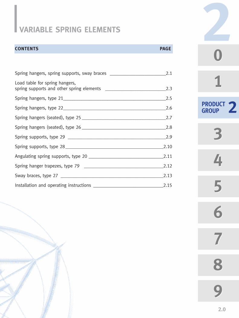
VARIABLE SPRING ELEMENTS
Spring hangers, spring supports, sway braces ________________________2.1
Load table for spring hangers,spring supports and other spring elements __________________________2.3
Spring hangers, type 21____________________________________________2.5
Spring hangers, type 22____________________________________________2.6
Spring hangers (seated), type 25 ____________________________________2.7
Spring hangers (seated), type 26 ____________________________________2.8
Spring supports, type 29 __________________________________________2.9
Spring supports, type 28__________________________________________2.10
Angulating spring supports, type 20 ________________________________2.11
Spring hanger trapezes, type 79 __________________________________2.12
Sway braces, type 27 ____________________________________________2.13
Installation and operating instructions ______________________________2.15
CONTENTS PAGE
0
1
3
4
5
6
7
8
9
0
1
3
4
5
6
7
8
9
2PRODUCTGROUP 2

Spring elementsTo compensate for slight vertical displace-ments in the piping, spring components areused as supports. The functioning of thesecomponents is based on preset helical coilsprings which exert a variable supportingload over the whole range of movementcorresponding to the given spring character-istics. Load variations resulting from this arelimited through corresponding specificationsbased on stress calculations for the piping -this depends on the sensitivity of thesystem.
The fundamental principles relevant for thefunction of the spring components are foundin the MSS SP 58 and VGB R 510 L guide-lines. See Technical Specifications, page 0.5.
LISEGA spring hangersVarious versions of spring elements, ideallysuited to whatever structural requirementsexist, are available. The optimum choicedepends on the installation situation.
Spring hangers, type 21This type, the one most frequently used, isfitted with an upper connection for suspen-
sion. It is installed whereverthe surrounding locationoffers a suitable connectionpoint and sufficientspace. The upperconnections can beuniversally adaptedwith standard com-ponents to any given
situation.
SPRING HANGERSSPRING SUPPORTS
2.1
Spring hangers, type 25This type is frequently used for
its simple installation, just sea-ting it on the existing steel. Theconnection is made by a rodpassing through the unit.
Spring supports, type 29If the installation location doesnot permit sus-
pension, then this model is asuitable alternative as a„prop“ support. Where thereis considerable horizontaldisplacement of the supportload, and steel slides onsteel, lateral forces canunder certain conditionshave an adverse effect onthe operation of the sup-port system. To take precautionsagainst this, the use of PTFE bearings isrecommended. In this case the counter bea-ring should have a stainless steel surface.
Spring hanger, type 21
Spring hanger, type 25
Spring support, type 29
�Type 29 with PTFEslide plate.
Recommended use of PTFE slide plates forspring supports type 29
To prevent constraints inthe system, thermalexpansion in the pipingand other piping compo-nents must not be hinde-red. The piping must there-fore be supported in a cor-respondingly elastic man-ner.

2.2
Angulating spring supports, type 20Unlike the spring support type 29,horizontal displacement can betaken up almost free of lateralforces by this design. This way that constraining fric-tional forces are completelyexcluded at all levels of move-ment, vertical and horizontal.
Sway braces, type 27These particular components act both intension and compression and are used tostabilize the piping and other plant com-ponents. An additional damping effect isobtained at the same time. The connectionparts correspond with those of ProductGroup 3.
With LISEGA sway braces, type 27, the following adjustmentscan be made:
➜ load presetting➜ free stroke➜ installation dimension
See also Installation and OperatingInstructions, page 2.17
Load setting and blockingSpring hangers and supports are preset at theworks to the installation load and blocked inboth directions of movement. Blocking isnecessary to take up additional loads duringpickling, flushing, or hydrostatic tests. The factory settings are carried out on elec-tronically controlled test benches:
➜ with spring hangers, values set at the factory are stamped onto a riveted nameplate.
➜ the installation position is marked on the travel scale.
➜ cold and hot settings are marked on the travel scale with a white and red sticker respectively.
➜ the blocking device can be blocked in any position. The blocking pieces can be reinserted in any required position.
Spring hangers and supports should be setin such a way that the spring load and thepiping weight correspond with the cold loadposition.The corresponding hot load position resultsfrom the theoretically determined pipe move-ment (travel) and the spring rate.The load difference between the cold andhot positions acts on the piping as a reac-tion force and is limited by the relevantdesign specifications.
Generally, the max. permissible load devia-tion amounts to 25% of the operating load.
Above and beyond that, constant hangersexerting a constant supporting load over thewhole travel range are to be used.
Selection of spring hangersA decisive factor for the reaction force is thestiffness of the spring rate value of the res-pective coil springs. To cover the widest pos-sible field of application using spring han-gers, the load ranges are divided into 5 tra-vel ranges.
Please see Technical Specifications page 0.13for details of usage. See also the selectiontable, pages 2.3 and 2.4, as well asInstallation and Operating Instructions, page2.15.
2
Design related advantages
➜ no welding (Types 20, 21, 27)➜ fully galvanized surfaces➜ specially prerelaxed springs➜ integrated tightening devices➜ adjustable blocking system➜ variable connection possibilities➜ TÜV suitability test➜ a wealth of experience from over a
million applications
Angulating spring support, type 20
Sway brace, type 27angulated arrangement
Sway brace, type 27single arrangement

SELECTION CRITERIA FOR SPRING HANGERS AND SUPPORTS
Permissible force variationThe permissible force variation betweencold load (installation load) position tohot load (operating load) position islimited internationally by common speci-fications for pipe stress analysis to max.25% of the operating load.
Maximum working travelAdditionally, to preclude functionalimpairment due to instability from extralong springs, a working travel of maximum 50mmshould not be exceeded.
Spring ratesTo cover as wide a field of applicationsas possible while adhering to thesestandards, LISEGA spring elements aredivided into 5 travel ranges with cor-respondingly different spring rates.
Extra long springsTravel ranges 4 & 5 relate to extra longsprings and should only be used aftertechnical evaluation of the whole situ-ation, especially in sensitive pipingsystems.
Design typesThe selection of the suitable designtype depends upon the respective sup-port configuration or installation situ-ation.
Economical unit sizeTo find the most economical size, thefollowing procedures apply:
SELECTION OF SPRING ELEMENTS
2.3
Spring hangers type 21, Spring hangers type 25, Spring supports type 29, Angulating spring supports type 20
21 8. 1825 8. 1829 8. 1820 82 14
26.6629.3332.0034.6637.3340.0042.6645.3348.0050.6653.3356.0058.6661.3364.0066.6669.3372.0074.6677.3380.00
133.3177.8266.6533.3
1066.6
21 7. 1825 7. 1829 7. 1820 72 14
20.0022.0024.0026.0028.0030.0032.0034.0036.0038.0040.0042.0044.0046.0048.0050.0052.0054.0056.0058.0060.00
100.0133.3200.0400.0800.0
21 6. 1825 6. 1829 6. 1820 62 14
13.3314.6616.0017.3318.6620.0021.3322.6624.0025.3326.6628.0029.3330.6632.0033.3334.6636.0037.3338.6640.00
66.688.9
133.3266.6533.3
21 5. 1825 5. 1829 5. 1820 52 14
6.667.338.008.669.33
10.0010.6611.3312.0012.6613.3314.0014.6615.3316.0016.6617.3318.0018.6619.3320.00
33.344.466.6
133.3266.6
21 4. 1825 4. 1829 4. 1820 42 14
3.333.664.004.334.665.005.335.666.006.336.667.007.337.668.008.338.669.009.339.66
10.00
22.233.366.6
133.3
21 2. 1825 2. 1829 2. 1820 22 14
0.830.911.001.081.161.251.331.411.501.581.661.751.831.912.002.082.162.252.332.412.50
8.316.633.3
21 1. 1825 1. 1829 1. 1820 12 14
0.410.450.500.540.580.620.660.700.750.790.830.870.910.951.001.041.081.121.161.201.25
4.18.316.6
21 D. 1925 D. 1929 D. 1920 D2 19
0.120.140.160.180.200.220.240.260.280.300.320.340.360.380.400.420.440.460.480.500.52
2.14.18.3
21 C2 19
29 C2 19
0.040.050.060.070.080.090.100.110.120.130.140.160.170.180.190.200.210.220.230.240.25
2.1
Spring rate c (N/mm)
Load (kN)
...1..
02.55.07.5
10.012.515.017.520.022.525.027.530.032.535.037.540.042.545.047.550.0
...2..
05
101520253035404550556065707580859095
100
Type number
Working travel (mm)
21 9. 1825 9. 1829 9. 1820 92 14
33.3336.6640.0043.3346.6650.0053.3356.6660.0063.3366.6670.0073.3376.6680.0083.3386.6690.0093.3396.66
100.00
166.6222.2333.3666.6
1333.3
...3..
0102030405060708090
100110120130140150160170180190200
...4..
0153045607590
105120135150165180195210225240255270285300
...5..
020406080
100120140160180200220240260280300320340360380400
21 3. 1825 3. 1829 3. 1820 32 14
1.661.832.002.162.332.502.662.833.003.163.333.503.663.834.004.164.334.504.664.835.00
11.116.633.366.6
Travel range �
�

2
2.4
� Travel range = 4th digit oftype designation For availability of component typein the different travel ranges, seedimension table pages 2.5 to 2.11.
� The use of extra long springsis only to be recommended inlimited cases because of therelatively large spring hysteresis.
22 5. 1926 5. 1928 5. 19
133.33146.66160.00173.33186.66200.00213.33226.66240.00253.33266.66280.00293.33306.66320.00333.33346.66360.00373.33386.66400.00
1333.32666.65333.3
22 4. 1926 4. 1928 4. 19
100.00110.00120.00130.00140.00150.00160.00170.00180.00190.00200.00210.00220.00230.00240.00250.00260.00270.00280.00290.00300.00
100020004000
22 3. 1926 3. 1928 3. 19
80.0088.0096.00
104.00112.00120.00128.00136.00144.00152.00160.00168.00176.00184.00192.00200.00208.00216.00224.00232.00240.00
80016003200
22 2. 1926 2. 1928 2. 19
66.6673.3380.0086.6693.33
100.00106.66113.33120.00126.66133.33140.00146.66153.33160.00166.66173.33180.00186.66193.33200.00
666.61333.32666.6
22 1. 1926 1. 1928 1. 19
53.3358.6664.0069.3374.6680.0085.3390.6696.00
101.33106.66112.00117.33122.66128.00133.33138.66144.00149.33154.66160.00
533.31066.62133.3
...3..
0102030405060708090
100110120130140150160170180190200
...1..
02.55.07.5
10.012.515.017.520.022.525.027.530.032.535.037.540.042.545.047.550.0
...2..
05
101520253035404550556065707580859095
100Spring rate c (N/mm)
Load (kN)
Type number
Working travel (mm)
DETERMINATION OF THE MOST FAVORABLE SIZE
1. Selecting the ideal spring hanger
Example:
Operating load F = 6000NPermissible deviation p � 25%Travel (up) s = 15mm
c � 25% · 6000N = 100N/mm15mm · 100%
Selection type 25 42 18Spring rate c = 66.6N/mmCold load FK = 7000N
2. Determination of the percentage offorce variation
Example:
6000N operation load, travel 15mm (up)A spring hanger type 25 42 18 was selected with a spring rateof c = 66.6N/mm
15mm · 66.6N/mm · 100% = 16.65%6000N
Spring hangers type 22. Variable spring hanger for seating type 26, spring supports type 28
Travel range �
2.5
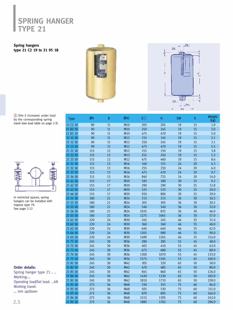
SPRING HANGERTYPE 21
Spring hangers type 21 C2 19 to 21 95 18
� Dim E increases under loadby the corresponding spring travel (see load table on page 2.3).
Order details:Spring hanger type 21 .. ..Marking:…Operating load/Set load: ...kNWorking travel: ... mm up/down
In restricted spaces, springhangers can be installed withtrapeze type 79. See page 2.12
Type
21 C2 1921 D2 1921 D3 1921 11 1821 12 1821 13 1821 21 1821 22 1821 23 1821 31 1821 32 1821 33 1821 34 1821 41 1821 42 1821 43 1821 44 1821 51 1821 52 1821 53 1821 54 1821 55 1821 61 1821 62 1821 63 1821 64 1821 65 1821 71 1821 72 1821 73 1821 74 1821 75 1821 81 1821 82 1821 83 1821 84 1821 85 1821 91 1821 92 1821 93 1821 94 1821 95 18
�A B �d2 E� H SW X Weight(kg)
809090909090
115115115115115115115155155155155180180180180180220220220220220245245245245245245245245245245275275275275275
111111111111121212131313131717171721212121212424242424303030303030303030303636363636
M10M10M10M12M12M12M12M12M12M16M16M16M16M20M20M20M20M24M24M24M24M24M30M30M30M30M30M36M36M36M36M36M42M42M42M42M42M48M48M48M48M48
205250475155250475155255475160255475840185290525920215305540
10351275245360640
12051490280405675
13001575305470845
14301810330505870
15151885
205245470145245470150250460155250470725180290525800215305540825
1065245360640980
1265285410680
10701345320485860
13301710355530895
13951765
191919191919191919242424243030303036363636364646464646555555555565656565657575757575
151515151515151515202020202525252530303030303535353535454545454550505050506060606060
1.93.05.02.13.15.53.85.38.64.36.09.7
14.09.2
12.820.029.016.520.532.046.057.031.040.062.090.0
114.048.063.089.0
133.0160.058.080.0
126.0182.0228.084.0
111.0164.0243.0296.0
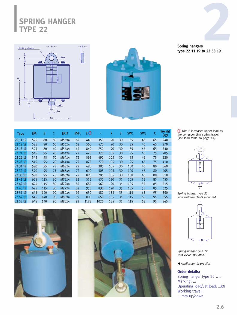
Type
22 11 1922 12 1922 13 1922 21 1922 22 1922 23 1922 31 1922 32 1922 33 1922 41 1922 42 1922 43 1922 51 1922 52 1922 53 19
�A B �d2C �d3 E � H R S SW1 SW2 XWeight
(kg)
525525525545545545590590590625625625645645645
808080959595959595
115115115140140140
606060707070757575808080909090
626262727272727272828282929292
909090
105105105105105105120120120135135135
303030303030303030353535353535
858585959595
100100100105105105115115115
464646464646464646555555656565
656565757575808080858585959595
240270340285320410360405510455515625550655865
440560840475595875490610890555685955630800
1175
350470750370490770385505785430560830480650
1025
M56x4M56x4M56x4M64x4M64x4M64x4M68x4M68x4M68x4M72x4M72x4M72x4M80x4M80x4M80x4
� Dim E increases under load bythe corresponding spring travel(see load table on page 2.4).
2
2.6
SPRING HANGERTYPE 22
Order details:Spring hanger type 22 .. ..Marking: …Operating load/Set load: …kNWorking travel: … mm up/down
Spring hangers type 22 11 19 to 22 53 19
blocking device
Spring hanger type 22with weld-on clevis mounted.
Spring hanger type 22with clevis mounted.
� Application in practice

Type
25 D2 1925 D3 1925 11 1825 12 1825 13 1825 21 1825 22 1825 23 1825 31 1825 32 1825 33 1825 41 1825 42 1825 43 1825 51 1825 52 1825 53 1825 61 1825 62 1825 63 1825 71 1825 72 1825 73 1825 81 1825 82 1825 83 1825 91 1825 92 1825 93 18
�A B�
9090909090
115115115115115115155155155180180180220220220245245245245245245275275275
350675200350675205355665210355675230395730265405740300465845350530900385605
1075415645
1110
M10M10M12M12M12M12M12M12M16M16M16M20M20M20M24M24M24M30M30M30M36M36M36M42M42M42M48M48M48
1313131313131313181818252525282828343434404040474747545454
245470145245470150250460155250470180290525215305540245360640300430700335500875370545910
380705230380705235385695250395715280445780325465800375540920440620990495715
1185535765
1230
2.84.92.13.15.53.55.18.43.75.38.98.0
11.518.614.518.029.026.035.056.040.053.079.044.066.0
111.067.092.0
143.0
�d2 �d4 H X max� Weight(kg)
Type B C d6 E
72 D9 28 125 95 12 872 19 28 125 95 12 872 29 28 150 115 14 1072 39 28 150 115 14 1272 49 28 190 140 18 1272 59 28 220 170 18 1272 69 28 260 200 23 1572 79 28 290 215 23 2072 89 28 290 215 27 2072 99 28 340 255 33 25
Load group
Order details:Spring hanger type 25 .. ..Marking: ..Operating load/Set load: …kNWorking travel: … mm up/down
2.7
SPRING HANGER TYPE 25
Spring hangers (seated)type 25 D2 19 to 25 93 18
� Dims B and X reduce under loadby the corresponding spring travel (see load table on page 2.3)
For special applications spring hangers type25 can be manufactured as trapeze units.
Base plateType 72 can be added totype 25 on request.
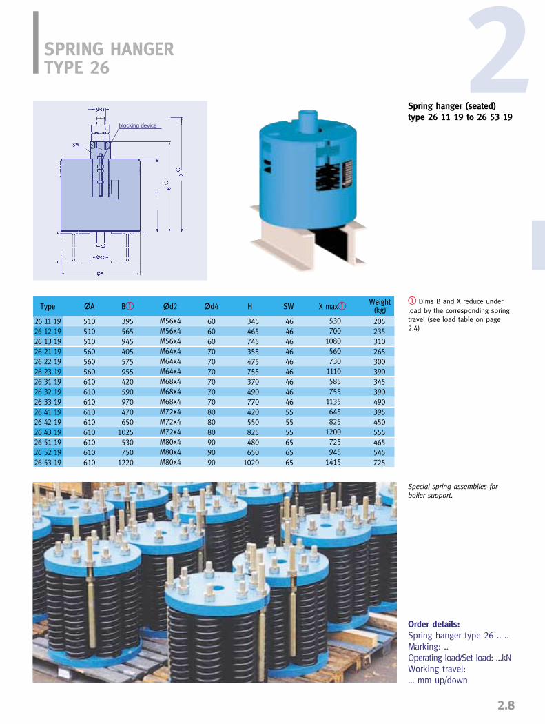
Type
26 11 1926 12 1926 13 1926 21 1926 22 1926 23 1926 31 1926 32 1926 33 1926 41 1926 42 1926 43 1926 51 1926 52 1926 53 19
�A
510510510560560560610610610610610610610610610
395565945405575955420590970470650
1025530750
1220
345465745355475755370490770420550825480650
1020
606060707070707070808080909090
464646464646464646555555656565
205235310265300390345390490395450555465545725
M56x4M56x4M56x4M64x4M64x4M64x4M68x4M68x4M68x4M72x4M72x4M72x4M80x4M80x4M80x4
530700
1080560730
1110585755
1135645825
1200725945
1415
B� �d2 X max��d4 HWeight
(kg)SW
2
2.8
� Dims B and X reduce underload by the corresponding springtravel (see load table on page2.4)
Order details:Spring hanger type 26 .. ..Marking: ..Operating load/Set load: …kNWorking travel: … mm up/down
SPRING HANGERTYPE 26
Spring hanger (seated)type 26 11 19 to 26 53 19
blocking device
Special spring assemblies for boiler support.

Type
29 C2 1929 D1 1929 D2 1929 D3 1929 11 1829 12 1829 13 1829 21 1829 22 1829 23 1829 31 1829 32 1829 33 1829 41 1829 42 1829 43 1829 51 1829 52 1829 53 1829 61 1829 62 1829 63 1829 71 1829 72 1829 73 1829 81 1829 82 1829 83 1829 91 1829 92 1829 93 18
�A �B
80909090909090115115115115115115155155155180180180220220220245245245245245245275275275
105125125125125125125150150150150150150190190190220220220260260260290290290290290290340340340
75959595959595
115115115115115115140140140170170170200200200215215215215215215255255255
10121212121212141414141414181818181818232323232323272727333333
36363636363636363636363636484848505050505050525252555555606060
210145245470145245470150250460155250470180290525210300535245360640300425695335500870370545910
80808080808080
100100100100100100120120120150150150170170170200200200200200200240240240
6888888
101010121212121212121212151515202020202020252525
270195305550195305550200310540205310550240360615270370625305430730360500790400575965440625
1010
2.63.24.36.63.44.67.25.67.6
11.16.38.4
13.011.916.025.020.024.337.034.044.068.053.068.097.060.084.0
133.091.0
118.0173.0
d6 FE� Weight(kg)�D�C H S
Type Load group øL1
70 19 16 C, D, 1 4070 39 16 2, 3 4070 49 16 4 6570 59 16 5 6570 69 16 6 11070 79 16 7 11070 89 16 8 15070 99 16 9 150
2.9
SPRING SUPPORTTYPE 29
Spring supportstype 29 C2 19 to 29 93 18
PTFE (Teflon) slide platesare recommended for con-siderable horizontal load displacements.
� Dim E is independent of the load setting. It variesunder load by the corresponding spring travel (see loadtable page 2.3). Adjustment possibility +30mm.
Order details: Spring support type 29 .. ..Marking: ..Operating load/Set load: …kNWorking travel: … mm up/down
øL1
Suitable extensions can beordered to bridge greaterinstallation heights.
Type 29 .9 15 - E…Load group

Type
28 11 1928 12 1928 13 1928 21 1928 22 1928 23 1928 31 1928 32 1928 33 1928 41 1928 42 1928 43 1928 51 1928 52 1928 53 19
�A
510510510560560560610610610610610610610610610
530530530580580580630630630630630630630630630
440440440490490490530530530530530530530530530
420420420420420420450450450450450450480480480
405535835450585880460595890505685
1075560750
1135
330450730370500775380510785425595965475655
1020
230260360310350460380430555440520740495580785
333333333333333333393939393939
606060656565656565707070757575
252525252525252525303030353535
464646464646464646555555656565
�B øD FE� Weight(kg)
SW�C H Sd6
2SPRING SUPPORTTYPE 28
Spring supportstype 28 11 19 to 28 53 19
� Dim E is independent of theload setting. It varies under loadby the corresponding spring travel(see load table page 2.4).Adjustment possibility + 30mm.
Order details:Spring support type 28 .. ..Marking: ..Operating load/Set load: …kNWorking travel: … mm up/down
2.10
blocking device
Application in practice

ANGULATING SPRING SUPPORTTYPE 20
Angulating spring supportstype 20 D2 19 to 20 92 14
Weld-on brackets type 35are foreseen as connectionparts (see page 3.8).
�Dim E is independent of theload setting. It varies under loadby the corresponding spring travel (see load table, page 2.3).Adjustment possibility + 50mm.
� Connection type
Order details:Angulating spring supporttype 20 .. .. with 2 weld-onbrackets 35 .. ..Marking: ..Operating load/Set load: …kNWorking travel: … mm up/down
2.11
� Installation dimensions greaterthan Emax on load reduction pos-sible. Shorter L dimensions can besupplied, but then without adjust-ment possibility of � 37.5mm.
Order details:Extension for angulatingspring supporttype 20 .9 ..L=... mm
Installation extension for angulating spring supporttype 20 D9 19 to 20 99 14
weld-on bracket �
Min. thread engagement
�
Type
20 D2 1920 12 1420 22 1420 32 1420 42 1420 52 1420 62 1420 72 1420 82 1420 92 14
�A
9090
115115155180220245245275
10101215152020303050
370370380390440470535650735815
45455058586565
100100130
15151921213131505262
260260260260300315370430505550
4477
1524457087
120
35 29 1335 29 1335 39 1335 49 1335 49 1335 59 1935 59 1935 69 1935 69 1935 79 19
15152023233030454560
99
1012121616222235
�d3 H R SGFWeld-on bracket
�Weight
(kg)E�
Type
20 D9 1920 19 1420 29 1420 39 1420 49 1420 59 1420 69 1420 79 1420 89 1420 99 14
A+50
325325330332382405470550635685
424248606076768989102
10101215152020303050
525525535547597675740835920
1015
1220122014651460146019501950192524252410
200200205215215270270285285330
895895
11351128107815451480137517901725
1.11.11.32.52.58.08.0
10.610.616.5
3.83.84.48.48.4
14.614.621.121.130.6
�DL �37.5
min at Lmin (kg)E +87.5 min-37.5�d3
L �37.5max� tube (kg/m)
G
weightE +87.5 max-37.5

2
2.12
SPRING HANGER TRAPEZESTYPE 79
� The 4th digit of the type desig-nation denotes the travel rangeof the spring hanger.1=50mm, 2=100mm, 3=200mm
�Permissible center load of theother load conditions see table3.5.3 page 0.5 (Nominal load 120 kN see load group 9)
�Dim E increases under load bythe corresponding spring travel(see load table on page 2.3)
�The maximum L dimensionsmay be increased to 2400mm,with load reduction of 5% foreach 100mm of extension.
Order details:Trapeze type 79 .. 11L= … mm
ø
Order details:Trapeze, type 79 .. 19 L= … mm
�
�
TrapezeType
79 D.� 1179 1. 1179 2. 1179 3. 1179 4. 1179 5. 1179 6. 1179 7. 1179 8. 1179 9. 11
�d2 L max
Weight (kg) L= 1000mm at travel rangeNominal load
(kN)�
1.252.55
10204080
120160200
M10M12M12M16M20M24M30M36M42M48
1400140016001600175021002100210021502200
B
80100100100120160200240260280
-1926274168
110159186243
162129304876
128189230297
202635386399
172241322403
1.11.62.02.02.74.36.18.39.3
10.3
�per 100mm
(kg)1 2 3
E dimensionapprox. �
travelrange �
123
3055
105
Notes �...� see above
Spring Hanger trapezestype 79 .. 11
For restricted spaces thedesign shown can bemanufactured as a special.
-50
TrapezeType
79 D.� 1979 1. 1979 2. 1979 3. 1979 3. 1979 4. 1979 4. 1979 5. 1979 5. 1979 6. 1979 6. 1979 7. 1979 7. 1979 8. 1979 8. 1979 9. 19
�d2 L maxNominal load
(kN)�
��
E� at Travel range
1 2 3 U A B X
1.252.5
51010202040408080
120120160160200
M10M12M12M16M16M20M20M24M24M30M30M36M36M42M42M48
170017001700900
180014001800125018001250240018002400120018001800
–290290315300345345405390445435505500560555610
385385390410395450450495480560550630625725720785
610610610630615685685730715840830900895
110010951150
80808080
120120140140180200260260300260300300
9090
115115115155155180180220220245245245245275
140140140140190190200200230250310310350310350350
15151520202525303035354545505060
Weight (kg) L= 1000 at travel range
-2428294153617793
138174214245242273335
2626313245606885
101156192244275286317390
30313739527482
108124200236296327378410495
1.71.71.71.72.72.73.23.24.45.17.67.69.27.69.29.2
�per 100 mm1 2 3

SWAY BRACETYPE 27
Sway bracetype 27 D2 19 to 27 62 19Maximum working travel25mm including free stroke
� Load setting is carriedout at the works in accor-dance with customer specifications.
� Dim E is independent ofload setting. Adjustmentpossibility �37.5mm.
� Weld-on brackets type35 and dynamic pipeclamps type 36 or 37 areforeseen as connectionparts.
Order details:Sway brace type 27 .2 19Marking: ...Operating load/Set load: …kNWorking travel: … mm up/down
If requested, sway bracescan be supplied with shop-fitted extensions
2.13
Extension for sway bracetype 27 D9 19 to 27 69 19
� Installation dimensions greaterthan Emax on load reduction pos-sible. Shorter L dimensions can besupplied, but then without adjust-ment possibility of �37.5mm.
Order details:Extension for sway bracetype 27 .9 19L-dim.: … mm
Min. thread engagement
Min
. thr
ead
enga
gem
ent
Weld-on bracket
Load adjustment
Free stroke adjustment
�
Type
27 D2 1927 12 1927 22 1927 32 1927 42 1927 52 1927 62 19
�A �d3 SGFweld-on bracket
Type �Nom. load
(kN)
0.521.252.505.00
10.0020.0040.00
4.18.3
16.633.366.6
133.3266.6
9090
115115155180220
9090909090
100100
10101215152020
640640650665730810875
50505055557575
295295300305355380445
15151921213030
99
1012121616
5.55.81011233962
0.12 0.420.41 1.040.83 2.081.66 4.163.33 8.336.66 16.66
13.33 33.33
35 29 1335 29 1335 39 1335 49 1335 49 1335 59 1935 59 19
E�Calibr. load� [kN]min max
Spring rate(N/mm)
C�37.5 H RWeight
(kg)
Type
27 D9 1927 19 1927 29 1927 39 1927 49 1927 59 1927 69 19
�D �d3 E � 75min maxA � 37.5
590590600610675735800
42424860607676
10101215152020
790 1600790 1600805 2000825 2000890 2000
1005 24001070 2400
200 1010200 1010205 1400215 1390215 1325270 1665270 1600
1.11.11.32.52.58.08.0
3.83.84.48.48.4
14.614.6
at Lmin (kg)L � 37.5 �min max tube (kg/m)
Weight
2
2.14
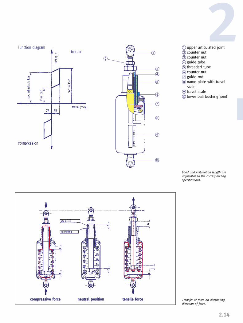
� upper articulated joint� counter nut� counter nut� guide tube� threaded tube� counter nut� guide rod name plate with travel
scale travel scale� lower ball bushing joint
�
�
�
�
�
�
�
�
Load and installation length areadjustable to the correspondingspecifications.
Transfer of force on alternatingdirection of force.
compressive force tensile forceneutral position
Function diagram

INSTALLATION ANDOPERATING INSTRUCTIONS
Spring hanger, type 21 (blocked)
Spring hanger, type 25 (blocked)
Spring hangers and spring supportstypes 20, 21, 22, 25, 26, 27, 28, 29
1. Transport and storageWhen transporting, threaded connectionsand travel stops must not be damaged.When stored in the open they should beprotected from dirt and moisture.
2. Delivery conditionUnless agreed otherwise, spring hangers andspring supports are delivered to the siteblocked in the installation position.When hangers or supports are blocked (travelstop in both directions), the spring plate islocked by a special blocking device in thehousing slots.
All spring hangers and supports are suppliedwith a riveted aluminum name plate fittedwith an integral travel scale.The following information is stamped on thename plate:
➜ order number if required➜ set load ➜ theoretical travel➜ spring rate of the hanger or support➜ marking and position number➜ test stamp if required
The serial number is stamped directly on the housing.
Spring support, type 29 (blocked)
2.15
Blocking device for singlespring models
Name plate for spring hanger
Spring hangers and sup-ports are used to compen-sate for the thermal move-ment to be expected inpiping systems. Fortrouble-free functioning,correct installation isessential, observing thefollowing instructions:
If specially ordered, the stops can be bolted securely tothe hanger or support after deblocking.
Securing clamp Fixing bolt
The blocking units for single spring models consist ofa set of hinged metal plates. Individual plates can beswivelled into any desired blocking position.

� upper connection� travel scale� blocking unit with securing band� name plate� lower connection (turnbuckle
with right-hand thread)� counter nut
On the travel scale, the theoretical operatingposition is marked with a red, and the theo-retical cold position with a white sticker.Also, the position of the spring plate is markedwith an X on the travel scale. The read out is made at the bottom edge ofthe spring plate.
2.1 Spring hangers, type 21Spring hangers, type 21, have upper andlower connections fitted with right-handthreads. At the top they consist of an internalthread engagement of limited depth, and atthe bottom a turnbuckle. The threads are filledwith grease and sealed with plastic caps.
2.2 Spring hangers, type 22The upper connection of these hangers issupplied as a lug for a connecting pin. Thelower connection consists of a turnbucklewith righthand thread.
2.3 Spring hangers, type 25 & 26Spring hangers, type 25 & 26 are providedwith a fixed support tube to accommodatethe connecting rod.
2.4 Spring supports, type 28 & 29The spring supports are provided with eitherone or four adjustable support tubes fittedwith a loosely mounted, but guided loadplate. The support tubes are screwed in andthe threads greased.
2.5 Angulating spring supports, type 20The angulating spring supports are providedat the top with an adjustable support tubeand a rotatable ball bushing joint, at thebottom with a fixed ball bushing joint. Thejoints provide a suitable connection to thecorresponding weld-on brackets type 35. Thesupport tube is screwed in and the threadsgreased.
�
�
��
�
�
Load chain with spring hanger
2
2.16
Blocking device forheavy dutyspring elementstype 22 to 28
Angulated spring support, type 20
Spring hanger, type 26
Spring hanger, type 22
Spring support, type 28
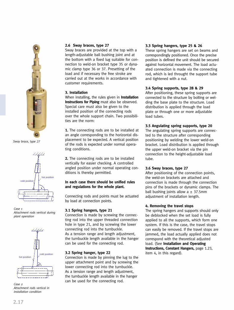
2.6 Sway braces, type 27Sway braces are provided at the top with alength-adjustable ball bushing joint and atthe bottom with a fixed lug suitable for con-nection to weld-on bracket type 35 or dyna-mic clamp type 36 or 37. Presetting of theload and if necessary the free stroke arecarried out at the works in accordance withcustomer requirements.
3. InstallationWhen installing, the rules given in InstallationInstructions for Piping must also be observed.Special care must also be given to theinstalled position of the connecting rodsover the whole support chain. Two possibili-ties are the norm:
1. The connecting rods are to be installed atan angle corresponding to the horizontal dis-placement to be expected. A vertical positionof the rods is expected under normal opera-ting conditions.
2. The connecting rods are to be installedvertically for easier checking. A controlledangled position under normal operating con-ditions is thereby permitted.
In each case there should be unified rulesand regulations for the whole plant.
Connecting rods and points must be actuatedby load at connection points.
3.1 Spring hangers, type 21Connection is made by screwing the connec-ting rod into the upper threaded connectionhole in type 21, and by screwing the lowerconnecting rod into the turnbuckle. As a tension range and length adjustment,the turnbuckle length available in the hangercan be used for the connecting rod.
3.2 Spring hanger, type 22Connection is made by pinning the lug to theupper attachment point and by screwing thelower connecting rod into the turnbuckle. As a tension range and length adjustment,the turnbuckle length available in the hangercan be used for the connecting rod.
2.17
3.3 Spring hangers, type 25 & 26These spring hangers are set on beams andcorrespondingly positioned. Once the preciseposition is defined the unit should be securedagainst horizontal movement. The load actu-ated connection is made via the connectingrod, which is led throught the support tubeand tightened with a nut.
3.4 Spring supports, type 28 & 29After positioning, these spring supports areconnected to the structure by bolting or wel-ding the base plate to the structure. Loaddistribution is applied through the loadplate or through one or more adjustableload tubes.
3.5 Angulating spring supports, type 20The angulating spring supports are connec-ted to the structure after correspondingpositioning by welding the lower weld-onbracket. Load distribution is applied throughthe upper weld-on bracket via the pinconnection to the height-adjustable loadtube.
3.6 Sway braces, type 27After positioning of the connection points,the weld-on brackets are attached andconnection is made through the connectionpins of the brackets or dynamic clamps. Theball bushing joints allow a � 37.5mmadjustment of installation length.
4. Removing the travel stopsThe spring hangers and supports should onlybe deblocked when the set load is fullyapplied to all the supports, which form onesystem. If this is the case, the travel stopscan easily be removed. If the travel stops arejammed, the load actually applied does notcorrespond with the theoretical adjustedload. (See Installation and OperatingInstructions, Constant Hangers, page 1.23,item 4, in this regard).
Sway brace, type 27
Case 1Attachment rods vertical duringplant operation
Case 2Attachment rods vertical in installation condition
cold position
cold position
hot position
hot position

��
��
��
2
2.18
� connecting rod� counter nut� lock nut� load tube� travel stop� travel scale� name plate
Example of an arrangement with type 25
5. Load readjustment
5.1 Spring hangers, spring supportsFor spring hangers the load can be readjustedby loosening or tightening the threaded rodsat the lock nut. For spring supports, the loadcan be readjusted by a corresponding adjust-ment of the load tube.Under all circumstances, however, the approp-riate technical department must be consultedbefore attempting any load readjustment.
5.2 Sway braces, type 27Load readjustment is made by rotating thethreaded tube (A). The large counter ring (B)is loosened to do this. In order to maintainthe E dimension, the resulting gap is com-pensated for by readjustment of the guidetube.
For sway braces, a free stroke can be set.To do this, the guide tube (C) opposite theinner guide rod (D) is to be unscrewed (loosen middle lock nut). The working travelreduces in the compression direction inaccordance with the free stroke selected.
6. CommissioningBefore commissioning it must be checkedthat each hanger or support allows the pre-calculated movement of the piping.The working travel of the hanger or supportcan be read off at the bottom edge of thespring plate as travel in the blocking slots,and read directly off the travel scale.
7. Checking and maintenanceThe correct functioning of the spring hangersor supports can be checked in all operatingsituations by noting the position of thespring plates. Under normal operating conditions no main-tenance is required.
�
Spring hanger type 22 with eyenuts as transport lugs
Hydraulic
cylinder
Hydraulic
cylinder
Hydraulic cylinder
Installation devices for readjust-ment of the set load for types22, 26 and 28. The devices canequally well be used asdeblocking aids.
�C�D
�A�B