SPI ConfigureUsersGuide
543
I-Configure User's Guide Version 2012 R1 February 2012/May 2012 DISO-PE-200007C-UPDATED
description
n
Transcript of SPI ConfigureUsersGuide

I-Configure User's Guide
Version 2012 R1
February 2012/May 2012
DISO-PE-200007C-UPDATED

Copyright
Copyright © 1991-2012 Intergraph Corporation. All Rights Reserved.
Including software, file formats, and audiovisual displays; may be used pursuant to applicable software license agreement; contains confidential and proprietary information of Intergraph and/or third parties which is protected by copyright law, trade secret law, and international treaty, and may not be provided or otherwise made available without proper authorization from Intergraph Corporation.
U.S. Government Restricted Rights Legend
Use, duplication, or disclosure by the government is subject to restrictions as set forth below. For civilian agencies: This was developed at private expense and is "restricted computer software" submitted with restricted rights in accordance with subparagraphs (a) through (d) of the Commercial Computer Software - Restricted Rights clause at 52.227-19 of the Federal Acquisition Regulations ("FAR") and its successors, and is unpublished and all rights are reserved under the copyright laws of the United States. For units of the Department of Defense ("DoD"): This is "commercial computer software" as defined at DFARS 252.227-7014 and the rights of the Government are as specified at DFARS 227.7202-3.
Unpublished - rights reserved under the copyright laws of the United States.
Intergraph Corporation P.O. Box 240000 Huntsville, AL 35813
Terms of Use
Use of this software product is subject to the End User License Agreement ("EULA") delivered with this software product unless the licensee has a valid signed license for this software product with Intergraph Corporation. If the licensee has a valid signed license for this software product with Intergraph Corporation, the valid signed license shall take precedence and govern the use of this software product. Subject to the terms contained within the applicable license agreement, Intergraph Corporation gives licensee permission to print a reasonable number of copies of the documentation as defined in the applicable license agreement and delivered with the software product for licensee's internal, non-commercial use. The documentation may not be printed for resale or redistribution.
Warranties and Liabilities
All warranties given by Intergraph Corporation about equipment or software are set forth in the EULA provided with the software or applicable license for the software product signed by Intergraph Corporation, and nothing stated in, or implied by, this document or its contents shall be considered or deemed a modification or amendment of such warranties. Intergraph believes the information in this publication is accurate as of its publication date.
The information and the software discussed in this document are subject to change without notice and are subject to applicable technical product descriptions. Intergraph Corporation is not responsible for any error that may appear in this document.
The software discussed in this document is furnished under a license and may be used or copied only in accordance with the terms of this license. No responsibility is assumed by Intergraph for the use or reliability of software on equipment that is not supplied by Intergraph or its affiliated companies. THE USER OF THE SOFTWARE IS EXPECTED TO MAKE THE FINAL EVALUATION AS TO THE USEFULNESS OF THE SOFTWARE IN HIS OWN ENVIRONMENT.
Intergraph is not responsible for the accuracy of delivered data including, but not limited to, catalog, reference and symbol data. Users should verify for themselves that the data is accurate and suitable for their project work.
Trademarks
Intergraph, the Intergraph logo, PDS, SmartPlant, FrameWorks, I-Convert, I-Export, I-Sketch, SmartMarine, IntelliShip, INtools, ISOGEN, MARIAN, SmartSketch, SPOOLGEN, SupportManager, SupportModeler, COADE, CAESAR II, CADWorx, PV Elite, CODECALC, and TANK are trademarks or registered trademarks of Intergraph Corporation or its subsidiaries in the United States and other countries. Microsoft and Windows are registered trademarks of Microsoft Corporation. All rights reserved. Oracle, JD Edwards, PeopleSoft, and Retek are registered trademarks of Oracle Corporation and/or its affiliates. Other brands and product names are trademarks of their respective owners.

I-Configure User's Guide 3
Contents Preface ........................................................................................................................................................ 11
What's New In I-Configure ........................................................................................................................ 13
I-Configure.................................................................................................................................................. 15
Exploring the I-Configure Interface ......................................................................................................... 17
Toolbar .................................................................................................................................................. 19 Project View Panel ................................................................................................................................ 20 Properties Panel.................................................................................................................................... 21
Search by property ......................................................................................................................... 22 Search by option switch.................................................................................................................. 22 Search by file section ..................................................................................................................... 23 Find Dialog Box .............................................................................................................................. 24
Overview Panel ..................................................................................................................................... 25 Detail Panel ........................................................................................................................................... 26 Status Bar ............................................................................................................................................. 27
Getting Started ........................................................................................................................................... 29
Tutorial Project ...................................................................................................................................... 30 Configuration Files ................................................................................................................................ 30
CreateTutorial_<Application Name>.xml ........................................................................................ 31 IsoDirList.xml .................................................................................................................................. 31 Project_Data.xml ............................................................................................................................ 31 ProjectConfig_<Application Name>.xml ......................................................................................... 31 ProjectList.xml ................................................................................................................................ 34 ProjectPipeline.xml ......................................................................................................................... 34 <Style Name>.xml .......................................................................................................................... 34
Sample Files ......................................................................................................................................... 35 Options .................................................................................................................................................. 36
I-Configure Setup Tools and Wizards ..................................................................................................... 37
Drawing Setup Tool .............................................................................................................................. 37 Specify the backing sheet .............................................................................................................. 42 Define drawing margins and report layout...................................................................................... 42 Customize report settings ............................................................................................................... 44 Define drawing frame attributes ..................................................................................................... 48 Update the style .............................................................................................................................. 49 View the results .............................................................................................................................. 49
Basic Setup Page (Drawing Setup Tool) .............................................................................................. 51 Drawing Areas Page (Drawing Setup Tool) .......................................................................................... 53 Material List Page (Drawing Setup Tool) .............................................................................................. 57 Weld List Page (Drawing Setup Tool) ................................................................................................... 61 Cut List Page (Drawing Setup Tool) ..................................................................................................... 64 Attributes Page (Drawing Setup Tool) .................................................................................................. 67
Add/Remove Attributes Dialog Box ................................................................................................ 68 Welding Wizard ..................................................................................................................................... 69

Contents
4 I-Configure User's Guide
Change settings for a single weld type........................................................................................... 69 Show Welds and Weld Numbering Page (Welding Wizard) .......................................................... 71 Select Weld Types Page (Welding Wizard) ................................................................................... 71 Weld Type Settings Page (Welding Wizard) .................................................................................. 71 Finish Page (Welding Wizard) ........................................................................................................ 72
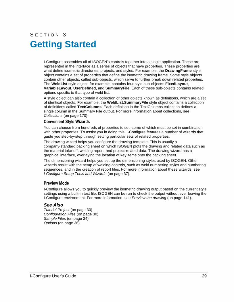
Dimensioning Wizard ............................................................................................................................ 73 Dimension Format Page (Dimensioning Wizard) ........................................................................... 73 Dimensioning Style Page (Dimensioning Wizard) .......................................................................... 76 Overall Dimensioning Page (Dimensioning Wizard) ...................................................................... 76 Gasket Dimensioning Page (Dimensioning Wizard) ...................................................................... 78 Elevations/Vertical Dimensions Page (Dimensioning Wizard) ....................................................... 79 Coordinates Page (Dimensioning Wizard) ..................................................................................... 80 Units Formatting Page (Dimensioning Wizard) .............................................................................. 81 Finish Page (Dimensioning Wizard) ............................................................................................... 81
Reports Wizard ..................................................................................................................................... 82 Add a report to a style .................................................................................................................... 82 Remove a report from a style ......................................................................................................... 83 Add a Report Page (Reports Wizard) ............................................................................................. 83 Report Definition Page (Reports Wizard) ....................................................................................... 83 Finish Page (Reports Wizard) ........................................................................................................ 84
Detail Sketch Manager .......................................................................................................................... 85 Configure a Detail Sketch ............................................................................................................... 91
Project Defaults and Attributes ................................................................................................................ 95
Add a new attribute ............................................................................................................................... 96 Edit an attribute ..................................................................................................................................... 97 Delete an attribute ................................................................................................................................. 98 Import PipeHeader attributes ................................................................................................................ 98 Create an attribute expression .............................................................................................................. 98 Project Defaults Dialog Box ................................................................................................................ 102
Project Defaults Tab (Project Defaults Dialog Box) ..................................................................... 102 Attributes Tab (Project Defaults Dialog Box) ................................................................................ 102
Attribute Dialog Box ............................................................................................................................ 108 Build Expression Dialog Box ............................................................................................................... 109 New Attribute Dialog Box .................................................................................................................... 109
Isometric Directories ............................................................................................................................... 113
Create a new isometric directory ........................................................................................................ 113 Connect to an isometric directory ....................................................................................................... 114 Delete an isometric directory .............................................................................................................. 114 Copy and paste an isometric directory ............................................................................................... 114 Disconnect from an isometric directory ............................................................................................... 115 Isometric Directory Object Properties ................................................................................................. 115
Isometric Projects ................................................................................................................................... 117
Isometric Project Common Tasks ....................................................................................................... 118 Create a new isometric project ..................................................................................................... 118 Define project access rights ......................................................................................................... 119 Enable an isometric project .......................................................................................................... 120 Delete an isometric project ........................................................................................................... 121 Copy and paste an isometric project ............................................................................................ 121

Contents
I-Configure User's Guide 5
New Project Dialog Box ................................................................................................................ 121 Enable Project Dialog Box ............................................................................................................ 122 Project Access Rights Dialog Box ................................................................................................ 122
Backup Isometric Projects .................................................................................................................. 122 Create a backup of an isometric project ....................................................................................... 122 Backup Project Dialog Box ........................................................................................................... 123
Import Isometric Projects .................................................................................................................... 124 Import a PipMan project ............................................................................................................... 125 Import a Spoolgen 4 project ......................................................................................................... 125 Import an I-Configure-based project ............................................................................................. 125 Import an isometric project from backup ...................................................................................... 126 Import Project Dialog Box ............................................................................................................. 127 Import Project from Backup Dialog Box ....................................................................................... 127
Isometric Project Object Properties .................................................................................................... 128 Name ............................................................................................................................................ 129 Path .............................................................................................................................................. 129 Source .......................................................................................................................................... 129 AppList .......................................................................................................................................... 129 AppCount ...................................................................................................................................... 130 WeldGaps ..................................................................................................................................... 130 ElbowConversion .......................................................................................................................... 131 ChangeStyleList ........................................................................................................................... 132 AccessRights ................................................................................................................................ 132 SystemXML .................................................................................................................................. 132 ProjectXML ................................................................................................................................... 132 LockedBy ...................................................................................................................................... 133 IsoDirectoryName ......................................................................................................................... 133 SystemMaterialManagerXML ....................................................................................................... 133 ProjectMaterialManagerXML ........................................................................................................ 133 SystemMaterialDataXML .............................................................................................................. 133 ProjectMaterialDataXML............................................................................................................... 133
Isometric Drawing Styles ........................................................................................................................ 135
Isometric Drawing Style Common Tasks ............................................................................................ 136 Create a new isometric drawing style ........................................................................................... 136 Select an isometric drawing style ................................................................................................. 137 View ISOGEN controls ................................................................................................................. 137 Copy and paste an isometric drawing style .................................................................................. 139 Delete an isometric drawing style ................................................................................................. 141 Save an isometric drawing style ................................................................................................... 141 Preview the drawing ..................................................................................................................... 141 New Style Dialog Box ................................................................................................................... 142 Drawing Preview Dialog Box ........................................................................................................ 143
Backup Isometric Style Settings ......................................................................................................... 144 Create a backup of an isometric drawing style ............................................................................ 144 Backup Style Dialog Box .............................................................................................................. 144
Import and Export Style Settings ........................................................................................................ 145 Import isometric drawing style settings from file .......................................................................... 146 Import isometric drawing style settings from backup ................................................................... 146 Import an isometric drawing style fragment.................................................................................. 147 Export isometric drawing style settings ........................................................................................ 147 Export an isometric drawing style fragment ................................................................................. 147 Import Style Dialog Box ................................................................................................................ 147

Contents
6 I-Configure User's Guide
Import Style from Backup Dialog Box ........................................................................................... 148 Isometric Drawing Style Object Properties ......................................................................................... 149
Name ............................................................................................................................................ 150 Path .............................................................................................................................................. 150 ExportBehaviour ........................................................................................................................... 150 StyleState ..................................................................................................................................... 150 StyleType ...................................................................................................................................... 150 ProjectName ................................................................................................................................. 150 Options ......................................................................................................................................... 151 CanWrite ....................................................................................................................................... 151 CanExport ..................................................................................................................................... 151
Techniques ............................................................................................................................................... 153
Fonts in Isometric Drawings ................................................................................................................ 153 Select a font for isometric drawing output .................................................................................... 154 Define a dynamic font for isometric drawing generation .............................................................. 154
Output a bar code on the isometric drawing ....................................................................................... 157 Add the barcode font to an AutoCAD backing sheet .......................................................................... 158 Bends .................................................................................................................................................. 159 Elbows ................................................................................................................................................. 159 Weld Lists ............................................................................................................................................ 159 Weld Logic .......................................................................................................................................... 160 Weld Constructions ............................................................................................................................. 162
Appendix: Isometric Drawing Style Objects ......................................................................................... 167
Collections ........................................................................................................................................... 170 Add an item to a collection ........................................................................................................... 171 Remove an item from a collection ................................................................................................ 172 Row Manipulation ......................................................................................................................... 172 Comment ...................................................................................................................................... 173
Alternative Text Object ........................................................................................................................ 174 Count ............................................................................................................................................ 174 AlternativeTexts ATexts Collection ............................................................................................... 174
Drawing Object.................................................................................................................................... 175 Visible ........................................................................................................................................... 175 Drawing.Content Object ............................................................................................................... 175 Drawing.Controls Object............................................................................................................... 185 Drawing.Definitions Object ........................................................................................................... 200 Drawing.Dimensions Object ......................................................................................................... 204 Drawing.Format Object................................................................................................................. 242 Drawing.Layers Object ................................................................................................................. 289 Drawing.DynamicFonts Object ..................................................................................................... 290 Drawing.EndConnections Object ................................................................................................. 291 Drawing.Revisions Object ............................................................................................................ 297 Drawing.Welds Object .................................................................................................................. 299
DrawingFrame Object ......................................................................................................................... 327 BottomMargin ............................................................................................................................... 327 TopMargin .................................................................................................................................... 328 LeftMargin ..................................................................................................................................... 328 RightMargin .................................................................................................................................. 328 CustomHeight ............................................................................................................................... 329 CustomWidth ................................................................................................................................ 329

Contents
I-Configure User's Guide 7
DXFUnits ...................................................................................................................................... 329 ReservedAreaDrawing ................................................................................................................. 329 ReservedAreaDrawingTop ........................................................................................................... 330 ReservedAreaMatList ................................................................................................................... 330 TemplateFile ................................................................................................................................. 330 TemplateFormat ........................................................................................................................... 330 Visible ........................................................................................................................................... 331 DrawingFrame.Attributes Object .................................................................................................. 331 DrawingFrame.TableAttributes Object ......................................................................................... 338 DrawingFrame.SymbolTable Object ............................................................................................ 341
MaterialList Object .............................................................................................................................. 346 ActiveList ...................................................................................................................................... 347 BoltAccumulation .......................................................................................................................... 347 BoltDiameterUnits ......................................................................................................................... 347 BoltLengthUnits ............................................................................................................................ 348 CentrelineLengths ........................................................................................................................ 348 ComponentsWithNoItemCodesInPCF .......................................................................................... 348 Drg1of1OnSingleIsos ................................................................................................................... 348 ErectAccumulation ........................................................................................................................ 349 FabAccumulation .......................................................................................................................... 349 FixedPipeAccumulation ................................................................................................................ 349 GasketAccumulation ..................................................................................................................... 349 ItemCodeLength ........................................................................................................................... 350 LinearQuantityStyle ...................................................................................................................... 350 MaterialsBySpool .......................................................................................................................... 350 MaterialListOverflow ..................................................................................................................... 350 MaterialListSplitting ...................................................................................................................... 351 OffshoreAccumulation .................................................................................................................. 351 OverflowDrawingID ....................................................................................................................... 351 SheetNumberFormat .................................................................................................................... 352 SmallxLargeNS ............................................................................................................................. 352 SpoolsMatchFull ........................................................................................................................... 352 SupportsWithMatchingNamesAccumulation ................................................................................ 352 TextFont ....................................................................................................................................... 353 Visible ........................................................................................................................................... 353 WastageArea1 .............................................................................................................................. 353 WastageArea2 .............................................................................................................................. 353 WastageArea3 .............................................................................................................................. 354 WastageArea4 .............................................................................................................................. 354 WastageArea5 .............................................................................................................................. 355 WastageArea6 .............................................................................................................................. 355 WastageArea7 .............................................................................................................................. 356 WastageArea8 .............................................................................................................................. 356 WastageArea9 .............................................................................................................................. 357 WeightsStyle ................................................................................................................................. 357 WeldAccumulation ........................................................................................................................ 357 MaterialList.FixedLayout Object ................................................................................................... 358 MaterialList.UserDefined Object ................................................................................................... 361 MaterialList.VariableLayout Object ............................................................................................... 380 MaterialList.SummaryFile Object ................................................................................................. 384 MaterialList.Transfers Object ....................................................................................................... 388
WeldList Object ................................................................................................................................... 390 ActiveList ...................................................................................................................................... 390

Contents
8 I-Configure User's Guide
ExtraRPadWelds .......................................................................................................................... 390 SlipOnFlangeWelds ...................................................................................................................... 391 Visible ........................................................................................................................................... 391 YTypeWelds ................................................................................................................................. 391 TackWeldNumbers ....................................................................................................................... 392 ClampWelds ................................................................................................................................. 392 WeldList.FixedLayout Object ........................................................................................................ 392 WeldList.VariableLayout Object ................................................................................................... 393 WeldList.UserDefined Object ....................................................................................................... 394 WeldList.SummaryFile Object ...................................................................................................... 399
CutList Object ...................................................................................................................................... 403 ActiveList ...................................................................................................................................... 403 IncludeAdditionalMaterial ............................................................................................................. 403 CutPieceID ................................................................................................................................... 404 CutPieceSequence ....................................................................................................................... 404 DecimalInchOutput ....................................................................................................................... 404 LengthToCL .................................................................................................................................. 404 LengthToBranchPoint ................................................................................................................... 405 OffshoreAllowance ....................................................................................................................... 405 OnShoreAllowance ....................................................................................................................... 405 ShopWeldAllowance ..................................................................................................................... 405 UseWeldGapData ......................................................................................................................... 406 UseTangentData .......................................................................................................................... 406 Visible ........................................................................................................................................... 406 CutList.FixedLayout Object .......................................................................................................... 407 CutList.UserDefined Object .......................................................................................................... 407 CutList.SummaryFile Object ......................................................................................................... 412 Supplementary Object .................................................................................................................. 415 Supplementary.AdditionalData Object ......................................................................................... 416 Supplementary.AuxiliaryPrograms Object.................................................................................... 417 Supplementary.BendingReport Object ......................................................................................... 419 Supplementary.CentreOfGravity Object ....................................................................................... 420 Supplementary.DataFiles Object .................................................................................................. 422 Supplementary.DetailSketches Object ......................................................................................... 445 Supplementary.DwgInfoFile Object .............................................................................................. 453 Supplementary.EquipmentTrim Object ........................................................................................ 455 Supplementary.Fonts Object ........................................................................................................ 457 Supplementary.HeatTreatment Object ......................................................................................... 458 Supplementary.InstrumentSKEYS Object .................................................................................... 460 Supplementary.NeutralFile Object ............................................................................................... 461 Supplementary.PipeLineAtts Object ............................................................................................. 467 Supplementary.ReferencePlanes Object ..................................................................................... 470 Supplementary.RepeatFile Object ............................................................................................... 473 Supplementary.ReportFiles Object .............................................................................................. 475 Supplementary.SiteWeldFile Object ............................................................................................. 477 Supplementary.SpoolAttributes Object ........................................................................................ 480 Supplementary.SpoolInformation Object...................................................................................... 481 Supplementary.TableAttributes Object......................................................................................... 484 Supplementary.TitleTexts Object ................................................................................................. 487 Supplementary.Traceability Object .............................................................................................. 488 Supplementary.PrintedMaterialList Object ................................................................................... 492

Contents
I-Configure User's Guide 9
Appendix: Alternative Text ..................................................................................................................... 495
Using Alternative Text ......................................................................................................................... 495 Examples ...................................................................................................................................... 497
Grouping of AText Listings .................................................................................................................. 498 Isometric Drawing Area ................................................................................................................ 498 Plotted Material and Cut Pipe List Heading Texts ........................................................................ 507 Specification Change Indication ................................................................................................... 513 Title Block/Drawing Frame ........................................................................................................... 513 Line Summary Area ...................................................................................................................... 515 Printed Material List ...................................................................................................................... 516 Weld Box Summary ...................................................................................................................... 516 Flat Spools and Flange Rotation .................................................................................................. 518 COMPIPE Material Control Links ................................................................................................. 519 SPOOLGEN (FFISYS) Screen Display ........................................................................................ 519 Reference Plane System .............................................................................................................. 523
Specify Alternative Texts .................................................................................................................... 523
Appendix: Automated Selection of Detail Sketches Based on Component Rotation ...................... 525
Conventions used in the calculation of rotation angle ........................................................................ 525 Conventions to be used in preparation of detail sketches .................................................................. 528 Applying the conventions .................................................................................................................... 528
Index ......................................................................................................................................................... 531


I-Configure User's Guide 11
This document is a user's guide for I-Configure™ and provides conceptual information and procedural instructions for creating and managing the isometric directories, projects and styles that are used by other 2D piping solutions and 3D plant design software products to generate isometric drawings and reports using ISOGEN
®. The content is identical to the online Help that
is delivered as part of the I-Configure software.
Intergraph gives you permission to print as many copies of this document as you need for non-commercial use at your company. You cannot reprint this document for resale or redistribution outside your company.
We welcome comments or suggestions about this documentation. You can send us an email at: [email protected].
Documentation updates for supported software versions are available from eCustomer https://crmweb.intergraph.com.
Preface

Preface
12 I-Configure User's Guide

I-Configure User's Guide 13
The following changes have been made to I-Configure:
Version 2012 R1
In previous versions of the software, the Preview Drawing command and the Drawing Setup wizard required that Volo View Express be installed on any workstation that was running I-Configure. That dependency has been removed from the software.
The Drawing Setup wizard user interface has been enhanced to provide more efficient ease of use. The wizard has also been renamed to Drawing Setup Tool. For more information, see Drawing Setup Tool (on page 37).
Previously, the -700 records were documented as a flat list with minimal explanation. They are now grouped by category with more detailed descriptions. For more information, see AttributeName (on page 332) in the DrawingFrame.Attributes DFAttributes Collection. (P2 AL:10694)
The software supports backing up and restoring isometric projects and isometric style settings. This functionality allows you to easily transfer projects and styles between sites. (P2 AL:10228)
For more information about backing up and restoring a Project, see Backup Isometric Projects (on page 122) and Import Isometric Projects (on page 123), respectively.
For information about backing up and restoring a Style, see Backup Isometric Style Settings (on page 143) and Import and Export Style Settings (on page 144), respectively.
Guidelines for creating user-specified dynamic fonts have been added to this document. For more information, see Fonts in Isometric Drawings (on page 153).
Version 2012
The WeldDiameterCalculationMethod (on page 323) property has been added to the Drawing.Welds object to support using cost factors to calculate weld diameter totals.
The software supports the ability to centre-justify text on the isometric drawing frame. For more information, see Justification (on page 336). (P3 AL:9225)
The Detail Sketch Manager allows you to add parameters to detail sketches when the drawing is generated. Each parameter has a method for calculating the value, based on the input. For more information about supported methods, see Grid Area in Detail Sketch Manager (on page 84). (P2 AL:10600)
Records -774, -775, -776, and -777 have been added to support the calculation and output of welding information to be split out between piping welds and support welds on the isometric drawing frame. For more information, see AttributeName (on page 332). (P2 AL:8940)
Added information to the Drawing.Revisions object description to clarify how it is enabled during isometric drawing generation. For more information, see Drawing.Revisions Object (on page 297). (P3 AL:105110)
Descriptions of the template style files delivered with the software have been added to the documentation. For more information, see Sample Files (on page 34).
What's New In I-Configure

What's New In I-Configure
14 I-Configure User's Guide

I-Configure User's Guide 15
S E C T I O N 1
I-Configure™ allows you to create and manage the isometric directories, projects and styles that are used by 2D piping solutions and 3D plant design products to generate isometric drawings and reports using ISOGEN
®.
ISOGEN is the industry-standard software for the automatic production of piping isometric drawings. It is integral to most of the major 2D piping solutions products and 3D plant design systems on the market and is used in the vast majority of process plant projects involving the design of pipe work.
A significant factor in the success of ISOGEN is its broad range of configuration options. Virtually everything about the piping isometric drawing – from the style of dimensioning and format of weld and part numbers to the location and layout of the material take-off – is configurable. This allows you to produce isometric drawings to your own specifications.
I-Configure has been specifically designed to simplify the customization of piping isometrics produced by ISOGEN. It allows ISOGEN's substantial array of control switches and files to be easily managed. Easy to learn and simple to use, I-Configure makes ISOGEN features available to more users and allows them to configure projects quickly and efficiently.
I-Configure includes the following features:
Support for projects and styles created in Project Manager (PipMan).
Connections to network projects.
Object-based user interface for the configuration of ISOGEN control files.
Explorer type windows to navigate the available projects and styles.
Wizards to quickly set-up and configure styles.
XML files for storage of project and style information.
Built-in drawing previewer to graphically examine on-the-fly the impact of modifications made to styles.
Password protection to avoid unauthorized alterations to projects and styles.
I-Configure

I-Configure
16 I-Configure User's Guide

I-Configure User's Guide 17
S E C T I O N 2
I-Configure brings all of ISOGEN's controls together in a single application. The Main window, which is shown in the example below, provides a unified interface to all of the ISOGEN settings. These settings are represented as a series of style objects that have properties, which can be defined according to your specific project requirements.
The I-Configure Main window is made up of several panels, each of which you can use to perform specific key tasks.
1 - Menu Bar
Click the name of a menu to display the menu commands. Many menu commands have equivalent keystrokes, such as CTRL+C for the Copy command, that you can use to quickly perform an action.
2 - Toolbar
Toolbars are groups of icons that provide rapid access to commonly used commands. They are an alternative to using menu items or keyboard shortcuts. For more information, see Toolbar (on page 18).
Exploring the I-Configure Interface

Exploring the I-Configure Interface
18 I-Configure User's Guide
3 - Project View Panel
The Project View panel displays all of the available isometric directories, isometric projects and isometric drawing styles in a tree structure format. For more information, see Project View Panel (on page 20).
4 - Style Objects Window
The Style Objects window is divided into two panels.
The Overview panel displays an overview of the most commonly used objects for both the drawing and report output. For more information, see Overview Panel (on page 24).
The Detail panel displays all of the objects of the selected style in a tree view format. For more information, see Detail Panel (on page 26).
6 - Properties Panel
The Properties panel displays the defined values for each property or the definitions for a collection. Selecting a property and pressing F1 opens the online Help and displays detailed information about the property. For more information, see Properties Panel (on page 20).
7 - Status Bar
The status bar contains summary information about the current project. For more information, see Status Bar (on page 26).

Exploring the I-Configure Interface
I-Configure User's Guide 19
Toolbar The I-Configure toolbar allows quick and easy access to some of the most frequently used commands.
New Isometric Directory - Creates a new isometric directory. For more information, see Isometric Directories (on page 113).
New Project - Creates a new project. For more information, see Isometric Projects (on page 117).
New Style - Creates a new style. For more information, see Isometric Drawing Styles (on page 135).
Connect to Isometric Directory - Connects to an existing isometric directory. For more information, see Connect to an isometric directory (on page 113).
Disconnect from Isometric Directory - Disconnects from an existing isometric directory. For more information, see Disconnect from an isometric directory (on page 115).
Enable Project - Enables the project for application. For more information, see Enable an isometric project (on page 120).
Save - Saves any changes that you have made to the current style XML file. For more information, see Save an isometric drawing style (on page 141).
Copy - Copies the selected item and places it in the Copy buffer so that it can be pasted elsewhere. You can copy isometric directories, projects, and styles.
Paste - Pastes the contents of the Copy buffer.
Delete - Deletes the selected item.
Project Defaults - Opens the Project Defaults dialog box in which you can view and modify project defaults and attribute data. For more information, see Project Defaults and Attributes (on page 95).
Preview Drawing - Creates an isometric drawing so that you can view the effect of the current style settings on the isometric drawing output. For more information, see Preview the drawing (on page 141).
Export Style - Exports the current style settings. For more information, see Export isometric drawing style settings (on page 147).
Add to Collection - Adds definitions to the selected collection. For more information, see Collections.
Remove from Collection - Removes definitions from the selected collection. For more information, see Collections.
Help - Opens the online Help file. You can also press F1 to open the online Help file.
See Also Exploring the I-Configure Interface (on page 17)

Exploring the I-Configure Interface
20 I-Configure User's Guide
Project View Panel Displays all of the available isometric directories, isometric projects, and isometric drawing styles in a tree view format. Collectively, these items make up the project hierarchy.
Clicking the + and - boxes next to the isometric directory or project expands or collapses the tree structure, allowing you to view the available styles and make modifications. You can use the Project View panel to create, edit, and manage isometric directories, projects, and styles.
As you select any style in the tree view, its properties are displayed in the Properties panel. Changing the value of each property ultimately determines the appearance of the isometric drawings and report file content produced when using the style in other products.
I-Configure displays existing PipMan projects and styles in magenta. PipMan projects and styles (as read directly from the drive) cannot be modified in the software, but they can be imported.
You can also import projects and styles from other products. For more information, see Import Isometric Projects (on page 123).
When you right-click an object in the Project View panel, the software displays a shortcut menu that provides quick access to the Copy, Paste, and Delete commands.
See Also Isometric Projects (on page 117) Properties Panel (on page 20) Detail Panel (on page 26) Overview Panel (on page 24) Toolbar (on page 18)

Exploring the I-Configure Interface
I-Configure User's Guide 21
Properties Panel Displays the values that are defined for each object property or the definitions of a collection. An object contains a set of related properties. When you change the object properties that belong to a Style, it alters the content and appearance of the isometric drawing and report file outputs that are produced when the style is used in those products that use I-Configure.
You can display and access style objects using the Detail panel. However, you can only modify object property values in the Properties panel. The values that object properties or collection definitions possess, are determined by their purpose. For example, a value can be a character or number, a filename and/or file path, an ISOGEN attribute, or some or other keyword used in an ISOGEN input control or output report file.
Alphanumeric - Click once in the Value box, and type the alphanumeric value.
Path - Double-click in the Value box to open the Browse to File dialog box. Navigate to the required file or folder, and click OK.
List - Double-click in the Value box, and select the required option from those available in the list.
Pop-up list - Double-click in the Value box, and select the required option from those available in the list.
Because of the hundreds of properties available, locating a specific property can be a daunting task. The Find command provides a dialog box that lets you search for specific property based on user-specified criteria. You can search for and locate properties based on a text string, option switch, or file section. .
Some properties are read only and are set automatically by the software when other
properties are defined.
You can display a shortcut menu when you right-click an object in the Properties panel. The shortcut menu provides quick access to the Copy, Paste, and Clear commands.
You can clear the value of a property using the Clear command on the shortcut menu.
Find Dialog Box (on page 24)
What do you want to do?
Search by property (on page 21)
Search by option switch (on page 22)
Search by file section (on page 23)

Exploring the I-Configure Interface
22 I-Configure User's Guide
Search by property 1. Click Tools > Find.
The Find dialog box appears.
2. Select Property, type a text string in the Property box, and press Enter.
The software lists all the properties containing the specified text string in the Search results list.
When you double-click a property in the Search results list, the software displays that property in the Properties panel.
Search by option switch 1. Click Tools > Find.
The Find dialog box appears.
2. Select Option Switch.
3. In the Option switch box, type the option switch number,

Exploring the I-Configure Interface
I-Configure User's Guide 23
4. Type the position of the option switch in the Position box.
The software lists all the properties that meet the specified criteria in the Search results list.
Search by file section 1. Click Tools > Find.
The Find dialog box appears.
2. Select File section to base the search on a specific section of an input file.
3. Select the file in the list:
When you double-click a property in the Search results list, the software displays that property in the Properties panel.
See Also Properties Panel (on page 20)

Exploring the I-Configure Interface
24 I-Configure User's Guide
Find Dialog Box Sets options for locating properties based on user-defined criteria. You can select only one search option.
Property - Locates the properties that match the specified text string. For example, if you type weight, the software locates all of the property names that match the text string. Type a text string.
Option switch and Position - Searches the option switches using a combination of number and position. This option is useful if are familiar with the option switch structure. Type the option switch number and position.
File section - Finds a specific section within the ISOGEN configuration files. Select MLD (material controls), WDF (welding controls), or DDF (miscellaneous controls).
Search results - Displays a list of properties that meet the specified criteria. When you double-click a property in the Search results list, the software displays the style property in the Properties panel.

Exploring the I-Configure Interface
I-Configure User's Guide 25
Overview Panel The Overview panel displays a simplified overview of the key properties of a style, for both the drawing and report output.
When you select any property from those shown, the Properties panel updates to show the location of the property and the object to which it belongs. Correspondingly, when you select the property in the Overview panel and click the Detail tab, the software automatically navigates to the object that the property belongs to and displays it in the Detail panel.
Wizards Toolbar
The Wizards toolbar provides quick access to the I-Configure wizards. The toolbar also provides quick access to the Detail Sketch Manager, which you can also access by clicking Wizards > Detail Sketch Manager.
Drawing Setup Tool - Allows you to customize the various parts of the isometric drawing. For more information, see Drawing Setup Tool (on page 37).
Welding Wizard - Allows you to manage the numbering, types and appearance of welds on the isometric drawing. For more information, see Welding Wizard (on page 68).
Dimensioning Wizard - Allows you to customize the style of dimensioning used on the isometric drawing. For more information, see Dimensioning Wizard (on page 73).
Reports Wizard - Allows you to customize the various report file outputs available in I-Configure. The reports selected apply only to the current style. For more information, see Reports Wizard (on page 82).
Detail Sketch Manager - Allows you to place parameters on the selected detail sketch so that correct relevant values, such as weld numbers, part number, and angles, are displayed on the isometric drawing. For more information, see Detail Sketch Manager (on page 84).
See Also Project View Panel (on page 20) Properties Panel (on page 20)
Exploring the I-Configure Interface
26 I-Configure User's Guide
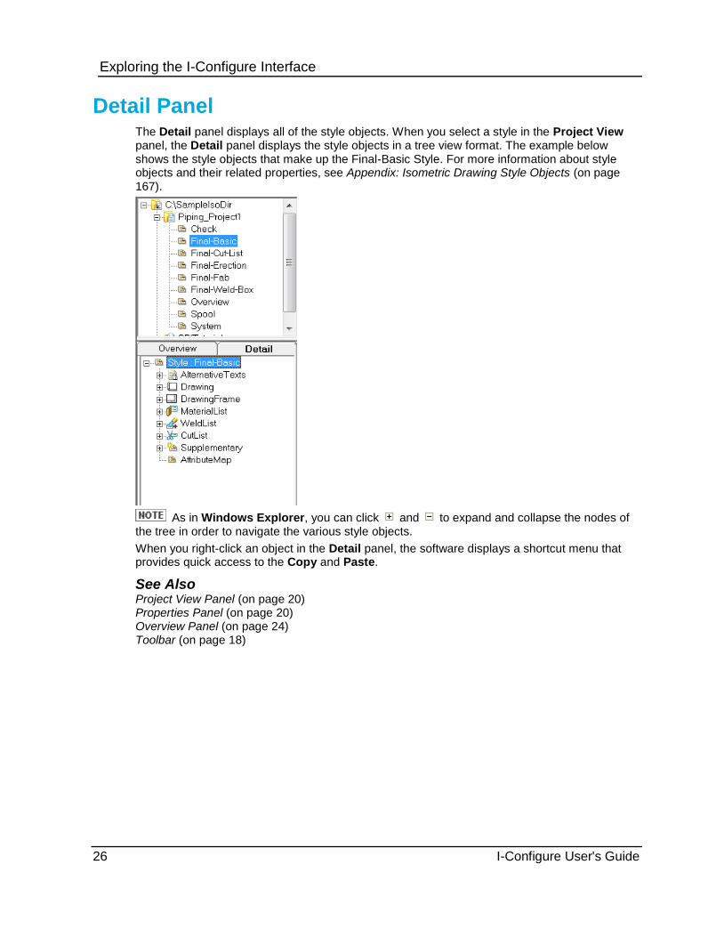
Detail Panel The Detail panel displays all of the style objects. When you select a style in the Project View panel, the Detail panel displays the style objects in a tree view format. The example below shows the style objects that make up the Final-Basic Style. For more information about style objects and their related properties, see Appendix: Isometric Drawing Style Objects (on page 167).
As in Windows Explorer, you can click and to expand and collapse the nodes of the tree in order to navigate the various style objects.
When you right-click an object in the Detail panel, the software displays a shortcut menu that provides quick access to the Copy and Paste.
See Also Project View Panel (on page 20) Properties Panel (on page 20) Overview Panel (on page 24) Toolbar (on page 18)

Exploring the I-Configure Interface
I-Configure User's Guide 27
Status Bar
The status bar is located at the bottom of the I-Configure Main window and displays the following details:
1 - Current Isometric Directory
This field updates when another Isometric directory is selected in the Project View panel.
2 - Current Project
This field updates when another project is selected in the Project View panel.
3 - Current Style
This field only shows a valid style name when a style is selected in the Project View panel.
4 - Contents of copy buffer
If the copy buffer is empty, as in after a Paste action, the field displays Empty.
See Also Project View Panel (on page 20) Properties Panel (on page 20) Detail Panel (on page 26) Overview Panel (on page 24) Toolbar (on page 18)

Exploring the I-Configure Interface
28 I-Configure User's Guide
I-Configure User's Guide 29
S E C T I O N 3
I-Configure assembles all of ISOGEN's controls together into a single application. These are represented in the interface as a series of objects that have properties. These properties are what define isometric directories, projects, and styles. For example, the DrawingFrame style object contains a set of properties that define the isometric drawing frame. Some style objects contain other objects, called sub-objects, which serve to further break down related properties. The WeldList style object, for example, contains four style sub-objects: FixedLayout, VariableLayout, UserDefined, and SummaryFile. Each of these sub-objects contains related options specific to that type of weld list.
A style object can also contain a collection of other objects known as definitions, which are a set of identical objects. For example, the WeldList.SummaryFile style object contains a collection of definitions called TextColumns. Each definition in the TextColumns collection defines a single column in the Summary File output. For more information about collections, see Collections (on page 170).
Convenient Style Wizards
You can choose from hundreds of properties to set, some of which must be set in combination with other properties. To assist you in doing this, I-Configure features a number of wizards that guide you step-by-step through setting particular sets of related properties.
The drawing wizard helps you configure the drawing template. This is usually a company-standard backing sheet on which ISOGEN plots the drawing and related data such as the material take-off, welding report, and project-related data. The drawing wizard has a graphical interface, overlaying the location of key items onto the backing sheet.
The dimensioning wizard helps you set up the dimensioning styles used by ISOGEN. Other wizards assist with the setup of welding controls, such as weld numbering styles and numbering sequences, and in the creation of report files. For more information about these wizards, see I-Configure Setup Tools and Wizards (on page 37).
Preview Mode
I-Configure allows you to quickly preview the isometric drawing output based on the current style settings using a built-in test file. ISOGEN can be run to check the output without ever leaving the I-Configure environment. For more information, see Preview the drawing (on page 141).
See Also Tutorial Project (on page 30) Configuration Files (on page 30) Sample Files (on page 34) Options (on page 36)
Getting Started

Getting Started
30 I-Configure User's Guide
Tutorial Project Any product that uses I-Configure, supports the installation of a sample tutorial project that you can use to help you get started with the software. The Create Tutorial Project utility can be used to create a sample isometric directory (SampleIsoDir) that contains a sample project. By default, the sample project contains a complete set of sample isometric styles that are used to determine the content and appearance of an ISOGEN drawing, as well as sample material data and sample piping specifications.
If you alter the tutorial project in anyway, you can use the Create Tutorial Project utility to restore its out-of-the-box default settings.
Do not use the tutorial project as a basis for production work. Subsequent installations of the same application overwrite the tutorial project. As such, If you make changes to the tutorial project that you need to keep, rename the SampleIsoDir folder or the project before re-installing any software that installs and runs CreateTutorial.exe as part of its installation, or before running Create Tutorial Project from the Start menu.
See Also CreateTutorial_<Application Name>.xml (on page 31) Configuration Files (on page 30)
Configuration Files I-Configure stores configuration information in a variety of XML files.
CreateTutorial_<Application Name>.xml (on page 31)
IsoDirList.xml (on page 31)
Project_Data.xml (on page 31)
ProjectConfig_<Application Name>.xml (on page 31)
ProjectList.xml (on page 34)
ProjectPipeline.xml (on page 34)
<Style Name>.xml (on page 34)
Although you can view configuration files using Internet Explorer; you must not modify their contents.

Getting Started
I-Configure User's Guide 31
CreateTutorial_<Application Name>.xml Controls the creation of the tutorial project. Each product installs its own version of this file.
The CreateTutorial configuration file uses the same syntax as the ProjectConfig_<application name>n.xml file--CopyFile and CreateFolder--but also supports the setting of project defaults to specific values.
See Also Tutorial Project (on page 30) ProjectConfig_<application name>.xml (on page 31) Configuration Files (on page 30)
IsoDirList.xml Contains the list of isometric directories set-up on the current machine. I-Configure creates this configuration file %ALLUSERSPROFILE%\Application Data\Alias.
Windows 2000, XP, 7 - ALLUSERSPROFILE = Documents and Settings\All Users
Windows NT - ALLUSERSPROFILE = WINNT\Profiles\All Users
See Also Configuration Files (on page 30)
Project_Data.xml Each project folder contains a Project_Data file, which is used to store application-specific project defaults and other project level data. For example, in the file name P1000_Data.xml, P1000 is the name of the project.
See Also Project Defaults and Attributes (on page 95) Configuration Files (on page 30)
ProjectConfig_<Application Name>.xml The structure of I-Configure projects is controlled by the ProjectConfig_<application name>.xml file configuration file. This configuration files is application-specific. That is, there is a file called ProjectConfig_Spoolgen.xml that defines SmartPlant Spoolgen projects and another called ProjectConfig_SPIsometrics.xml for SmartPlant Isometrics projects. In a default set, the ProjectConfig_<application name>.xml file is delivered to <Installation Folder>:\Program Files\Common Files\Intergraph\I-Configure\Application Data folder.
Although projects are application-specific, they can be enabled for multiple applications from the same source, if necessary. The project configuration file defines:
Any data files that must be copied to the project (or style).
Any folders that must be created.
Any mandatory styles that must be created. For example, SmartPlant Spoolgen must have a style called SGImport and one called Spool.
Any application-specific project defaults.

Getting Started
32 I-Configure User's Guide
When you create a new I-Configure project, you must use the Application list to specify the associated application. The software displays a list of supported applications in the Application list on the New Project dialog box, depending on what products are installed.
Using a User-Defined ProjectConfig_App.xml File
If a file with the name UserProjectConfig_<application name>.xml is found in the same folder as the supplied ProjectConfig_<application name>.xml file, it is used in preference to define the project structure, style content, and so on. This allows you to create a user-specific project configuration that is not overwritten by the next installation of I-Configure. For example, if both UserProjectConfig_SPIsometrics.xml and ProjectConfig_SPIsometrics.xml are found in the same folder, the software uses the former XML configuration file when you set-up a new project for SmartPlant Isometrics.
Initial Settings
New syntax in ProjectConfig_<application name>.xml file allows you to specify an initial setting (in the form of an XML file) for any property using the following syntax:
<SetProjectProperties PROPERTY='FILENAME' />
Consider the following example:
<SetProjectProperties
WeldGaps='$APPCONFIG$\Application Data\WeldGaps_Template.xml'
ElbowConversion='$APPCONFIG$\Application
Data\ElbowConversion_Template.xml'/>
I-Configure then loads the specified property with the contents of the specified file.
See Also Create a New Isometric Project (on page 118) Enable an Isometric Project (on page 120) Project Defaults Tab (Project Defaults Dialog Box) (on page 102) Configuration Files (on page 30)

Getting Started
I-Configure User's Guide 33
Create a user template
1. Create a new isometric drawing style (on page 136) using your company-standard backing sheet and settings.
2. Save the style XML file, and copy it to a folder designated to hold your user-defined templates. For example, you can create a folder called CompanyTemplates or UserTemplates.
File paths in the project/style hierarchy are automatically converted to use $PROJECT$ or $STYLE$ instead of the actual file path. This means that the style XML files can readily be copied between styles and do not need modification.
3. Make a copy of the ProjectConfig_<application name>.xml file and save it as UserProjectConfig_<application name>.xml.
Never modify the ProjectConfig_<application name>.xml file directly
4. Using the steps below, modify the UserProjectConfig_<application name>.xml file to reference your new template.
5. Immediately after the <AppSpecificProjectConfiguration> tag, create additional CreateFolder and/or CopyFile commands to create and populate new folders in the project folder. <AppSpecificProjectConfiguration Source="Alias">
<!-- Do the following for all projects -->
<CopyFile From="$APPCONFIG$\Application Data\ProjectPipeline.xml"
To="$PROJECT$\"/>
<!-- Create the SmartPlant Isometrics required folders under the project
-->
<CreateFolder Name="$PROJECT$\Inputs"/>
<CreateFolder Name="$PROJECT$\Pipes"/>
<CreateFolder Name="$PROJECT$\Data"/>
<CreateFolder Name="$PROJECT$\Data\Materials"/>
<CreateFolder Name="$PROJECT$\Data\Sketches"/>
6. Between the <Optional-Styles> and </Optional-Styles> tags, delete existing <Style> blocks to reduce the number of styles that are available when a project is created, and add new entries, pointing to your company-specific template. <Style Name="CoSpecific"
Template="\\server\CompanyTemplates\CoSpecific.xml" >
<CopyFile From="\\server\CompanyTemplates\CoSpecific.dwg"
To="$STYLE$\" />
<!-- Create standard Style directories -->
<CreateFolder Name="$STYLE$\Drawings"/>
<CreateFolder Name="$STYLE$\Reports"/>
<CreateFolder Name="$STYLE$\Messages"/>
</Style>
7. Save your changes.
The ProjectConfig_<application name>.xml file is updated when a new version of I-Configure is installed (CreateTutorial.exe overwrites all tutorial project files). Creating the UserProjectConfig_<application name>.xml file prevents any changes you make from being lost.

Getting Started
34 I-Configure User's Guide
ProjectList.xml Each isometric folder contains a ProjectList.xml file, which contains a list of projects and styles.
See Also Configuration Files (on page 30)
ProjectPipeline.xml The ProjectPipeline.xml file is an application-specific configuration file that can be present in the project folder. The ProjectPipeline.xml file contains the user-specified extensions to pipeline, component, weld and bolt attributes that have been defined for the project.
See Also Pipeline Attributes (on page 104) Component Attributes (on page 106) Weld Attributes (on page 106) Bolt Attributes (on page 106) Project Defaults Tab (Project Defaults Dialog Box) (on page 102) Configuration Files (on page 30)
<Style Name>.xml Each style folder contains a <Style Name>.xml file, such as Final-Basic.xml or Check.xml, which is used to store style configuration data for that isometric drawing style. To help you get started with I-Configure, a set of template styles is delivered with the software. However, before a style can be used by an application, the style must first be exported.
If you have not already exported the style, the application can perform this step for itself.
For list of the template styles delivered with the software, see Sample Files (on page 34).
See Also Export Isometric Drawing Style Settings (on page 147) Isometric Drawing Styles (on page 135) View Isogen Controls (on page 137)

Getting Started
I-Configure User's Guide 35
Sample Files To help you get started, I-Configure provides sample files that you can use to help you get started using the software.
Backing sheets - During a default installation of the software, a set of backing sheets, commonly referred to as drawing frames, is delivered to the [Installation Drive]:\Program Files\Common Files\Intergraph\I-Configure\Backing Sheets folder
Template files - During a default installation, a set of template styles is delivered to the <Installation Folder>:\Program Files\Common Files\Intergraph\I-Configure\Templates folder. The template styles are listed below,
Style Name Style Template File Style Description
Check Check.xml Designed for checking the routing of the pipeline against the 3D model or 2D drawing. Contains an overall dimensioning style with minimum detailing. There is no integral BOM material list and no external reporting. The isometric is configured for internal use and is not for issue.
Final-Basic Final-Basic.xml Designed for production release. Contains a fully detailed representation of the pipeline complete with Fabrication and Erection BOM materials listing. The Material Control File report is generated.
Final-Cut-List Final-Cut-List.xml Designed for production release. Contains a fully detailed representation of the pipeline, complete with Fabrication and Erection BOM materials listing. Pipeline cut piece references are output along with an integral cutting list table.
Final-Erection Final-Erection.xml Designed for production release. Contains a fully detailed representation of the pipeline, complete with an Erection BOM materials listing.
Final-Fab Final-Fab.xml Designed for production release. Contains a fully detailed representation of the pipeline, complete with a Fabrication BOM materials listing.
Final-Weld-Box Final-Weld-Box.xml Designed production release. Contains a fully detailed representation of the pipeline, complete with a Fabrication and Erection BOM materials listing. Pipeline welding numbering references are output along with an integral welding list table.

Getting Started
36 I-Configure User's Guide
Style Name Style Template File Style Description
Spool Spool.xml Designed for release to the Fabricator. Contains a fully detailed representation of the separate spool sections of the pipeline, complete with a Fabrication BOM materials listing. Pipeline welding numbering and cut piece references are output along with the welding and cut list tables. The Material Control File, Cut List, Weld Summary, and Spool Information file reports are generated.
Flat-Spool Flat-Spool.xml Designed for release to the Fabricator. Contains a fully detailed representation of the spool sections of the pipeline, complete with a Fabrication BOM materials listing. The spools are laid out in a flat orientation to maximize the number of legs flat with the fabrication work surface. Pipeline welding numbering and cut piece references are output along with the welding and cut list tables. The Material Control File and Weld Summary file reports are also generated.
See Also <Style Name>.xml (on page 34) TemplateFile
Options In the Options dialog box, you can specify whether the drawing units used for the project are Metric or Imperial. Drawing units impact the text positioning of attributes and dimensional properties, such as CharHeight, CharWidth, that are used by several I-Configure style objects. The value that you enter for a property should be a real number. For example, if you set drawing units to millimetres, enter 3 or 3.0 for 3mm. If you set the drawing units to inches, enter 0.125 for 1/8 inch.
Using the Options dialog box, you can also control how paths are displayed in the Project View panel for network projects. To use UNC paths, select the Use UNC path when creating network isometrics directories checkbox. Alternatively, particularly when you set up an isometric project on a network server (on page 119) with long path names that can exceed the current ISOGEN path length limitation, clear the checkbox to display the path using a mapped drive.
To access the Options dialog box, click Tools > Options.

I-Configure User's Guide 37
S E C T I O N 4
To customize and define isometric drawing output, you can set hundreds of properties, some of which must be set in combination with other properties. To assist you, I-Configure features a number of tools and wizards that guide you step-by-step through setting particular sets of related properties.
The Drawing Setup Tool (on page 37) helps you configure the drawing template. This is usually a company standard backing sheet on which ISOGEN plots the drawing and related data such as the material take-off, welding report, and project-related data. The drawing setup wizard has a graphical interface, overlaying the location of key items onto the backing sheet.
The Dimensioning wizard (on page 73) helps you set up the dimensioning styles used by ISOGEN. Other wizards include the Welding wizard (on page 68), which assists with the setup of welding controls such as weld numbering styles and numbering sequences, and the Reports wizard (on page 82), which assists in the creation of reports.
Another useful tool is the Detail Sketch Manager (on page 84), which configures detail sketches for isometric drawing output.
You can access these tools and wizards using the Wizards menu or the Wizards toolbar on the Overview panel.
Drawing Setup Tool
Customizes the content and format of the isometric drawing for the selected isometric drawing style. If the default settings for a specific drawing style are not sufficient for the drawings you want to generate, you can use the Drawing Setup Tool to modify those settings. For example, you can specify a company-standard backing sheet rather than using one of the templates delivered with the software. You can graphically define the position of the drawing area on the backing sheet and specify which user-defined reports, if any, you want ISOGEN to output on the drawing. You can also use the tool to define the attributes that display on the drawing frame. The options that you define in the tool can then be saved to the current isometric drawing style so that they can be applied to the generated drawings.
The Drawing Setup Tool consists of a series of tabbed pages, each of which contains a set of options and properties that are specific to a particular aspect of the drawing setup. The pages listed below appear by default for each isometric drawing style.
Basic Setup
Drawing Areas
Attributes
I-Configure Setup Tools and Wizards

I-Configure Setup Tools and Wizards
38 I-Configure User's Guide
If a user-defined Material List, Weld List, or Cut List report is currently associated with the selected isometric drawing style, or if you choose to add one of those reports during the Drawing Setup Tool process, a tabbed page specific to that report type is automatically displayed so that you can define those settings as well. The example below shows the complete set of tabbed pages that can display in the tool.
The above example also shows the vertical and horizontal toolbars that display in the tool. The commands on these toolbars provide options for navigating through the tool and for manipulating the view of the backing sheet. For example, you can adjust the view to display the entire backing sheet, or you can focus on a specific area, such as the drawing frame. You can also increase and decrease the viewing area. Decreasing causes everything within the window to appear larger, while increasing causes everything within the window to appear smaller. Toolbar commands are also available that allow you to control the content and layout of the user-defined reports and the attributes that are plotted in the title block. The table below lists the toolbar commands and provides a description for each.
Zoom In/Out - Increases or decreases the display size of the drawing template. You can zoom in to get a closer view of an area or zoom out to view more of the drawing template at a reduced size. Click the left mouse button and drag the pointer upward in the window to increase the view of an object as though you were moving closer to it. Drag the pointer downward in the window to reduce the view as though you are moving further away from the object.
Zoom Window- Increases the view magnification of an area in the drawing template that you define by creating a fence.
Zoom to Fit - Displays the entire contents of the drawing template in the window.
Pan - Repositions the drawing template in the display window so that you can view another section of the template without changing the view magnification.
Add / Remove Attributes - Opens the Add/Remove Attributes dialog box (on page 68). This dialog box allows you to specify the attributes that are available in the Attribute list in the Attributes Grid window. The command is available only when the Attributes page is active.
Add Column - Inserts a column to the selected report so that an additional attribute can be plotted in the report. This command is available only when the Material List, Weld List, or Cut List page is active.
Delete Column - Removes the selected column of component attribute data from the plotted report. This command is available only when you select a Column category label on the Material List, Weld List, or Cut List page.

I-Configure Setup Tools and Wizards
I-Configure User's Guide 39
Zoom to List Attributes - Zooms in on the selected attribute. Each time you click Zoom to
List Attributes , the view zooms to the selected attribute in the title block of the drawing frame or on the reports.
Previous Page - Returns to the previous page of the tool.
Next Page - Proceeds to the next page of the tool.
Help - Opens the on-line documentation delivered with the software and displays information about the tool.
Exit - Closes the tool. If you have not saved your changes, the software prompts you to do so.
Save - Writes the options and parameters that you have defined to the current style.
Cancel - Undoes the options and parameters that you have defined.
The four graphic control commands on the vertical toolbar (Zoom In/Out , Zoom
Window , Zoom to Fit , and Pan ) can be used any time while running the tool. The availability of the remaining vertical toolbar commands is determined by the active page.
You can navigate back and forth sequentially through the pages using Previous Page
and Next Page on the horizontal toolbar. Alternatively, click the tab to go directly to a specific page.
Moving and Resizing Windows
The Drawing Areas, Material List, Cut List, Weld List, and Attributes Grid windows in the Drawing Setup Tool work slightly differently than windows in other applications. These windows can be displayed, hidden, docked, maximized, tabbed, or made to float.
The following tips will help you manage windows effectively. As you are moving windows, remember that it is the placement of the cursor, not the window, that indicates where you are placing the window you are dragging. Look for the blue shadow indicator box that shows you where the window will be placed when you release the mouse button.
To automatically hide a window
1. Click in the top right corner of a docked window. The window is placed vertically on the application border on the side to which it was docked.
2. Move your cursor over the window name on the border to display the window, temporarily, where it was previously displayed. As you move your cursor away, the window automatically hides again.
The following illustration shows a normal view of the Drawing Areas window and a view with the window placed on the application border.

I-Configure Setup Tools and Wizards
40 I-Configure User's Guide
To turn off Auto-Hide mode
1. Place your cursor on the window name to show the hidden window.
2. When the window appears, click the button to place it where it was previously docked.
To undock a window
Double-click the title bar of a docked window to undock it and display it as a floating window.
To maximize a window
Double-click a floating, undocked window to dock it against the top border of the software window. This action maximizes the window as much as possible considering the placement of other tool and list view windows.
If windows are already docked along the top border of the software and there is no open space along the border, then you cannot maximize another window. As long as some portion of the top border does not have a window docked against it, you can minimize a new window, and the software will place it in that open space.
To dock a floating window
Click and drag the title bar of the floating window to dock it. As you begin to drag a docking window, it displays as shown in the example below.

I-Configure Setup Tools and Wizards
I-Configure User's Guide 41
Drag the window over one of the icons. Each icon docks the window in a different location - top, bottom, left or right. As the cursor passes over an icon, a blue box displays, showing you how the docked window will appear. The example below illustrates the relationship between the icon and docking location. The shaded blue box provides a preview of how the docked window will appear.
What do you want to do?
Specify the backing sheet (on page 41)
Define drawing margins and report layout (on page 42)
Customize report settings (on page 44)
Define drawing frame attributes (on page 48)
Update the style (on page 49)
View the results (on page 49)

I-Configure Setup Tools and Wizards
42 I-Configure User's Guide
Specify the backing sheet 1. Select an isometric drawing style in the Project View panel.
2. Click Drawing Setup Tool on the Wizards toolbar. Alternatively, click Wizards > Drawing Setup Tool.
The Drawing Setup Tool appears.
3. On the Basic Setup page, click Browse , and navigate to the backing sheet that you want to use.
A large selection of pre-formatted backing sheets is delivered with the software to the [Installation Drive]:\Program Files (x86)\Common Files\Intergraph\I-Configure\Backing Sheets folder.
4. Select the required drawing output format. The default setting is Smart DWG (DWG).
5. Set the required drawing size. If you select Custom, you must enter values for Width and Height.
6. Under Reports, specify the reports that you want ISOGEN to plot on the isometric drawing. If a user-defined material list is to be plotted, you must specify the required number of sections. By default, two sections are output on the material list.
7. Click Save .
Define drawing margins and report layout You can customize the left, right, top, and bottom margins of the drawing area, either interactively with the mouse or by typing new values in the Drawing Areas window. Likewise, you can use either method to set the start positions of where ISOGEN plots the the material, weld, and cut lists on the isometric drawing.
Set Drawing Margins Graphically
1. On the Drawing Areas page, place the cursor on the grab handle for the margin you want to change.
The cursor updates from a pointer to a two-headed arrow cross, indicating the direction in which you can drag the boundary.
Alternatively, place the cursor on one of the boundaries. The cursor updates from a pointer to a cross-hair, indicating that the margin is ready to be resized.

I-Configure Setup Tools and Wizards
I-Configure User's Guide 43
2. Drag the boundary to the new position, and then release the mouse.
As you drag the boundary, the corresponding margin value in the Drawing Areas window dynamically updates.
To accurately fit the drawing area, zoom in to each corner of the area being defined.
Using the corner grab handles, you can move two margins simultaneously while the other two margins remain unchanged.
Grab handle 1: Resizes the left and top margins.
Grab handle 2: Resizes the right and top margins.
Grab handle 3: Resizes the right and bottom margins
Grab handle 4: Resizes the left and bottom margins.
Set Drawing Margins Using the Grid
1. Expand Drawing Area Margins in the Drawing Areas window, and click the margin you want to resize.
2. Type the new value.
The drawing boundary box in the View window updates accordingly.

I-Configure Setup Tools and Wizards
44 I-Configure User's Guide
Set Report Start Position Graphically
1. On the Drawing Areas page, place the cursor on the appropriate report anchor.
The cursor updates from a pointer to a cross-hair, indicating that the anchor is ready to be moved.
In the above example, the numbers underneath the cross-hairs indicate the X and Y coordinate values.
2. Move the anchor to the required location, and then release the mouse.
As you drag the anchor, the corresponding X and Y values that display with the anchor and in the Drawing Areas window dynamically update.
Set Report Data Start Position Using the Grid
1. Expand the appropriate list category in the Drawing Areas window, click X, and type the new value.
2. Click Y, and type the new value.
The drawing boundary box in the View window updates accordingly.
Customize report settings You can use the grid to define formatting properties such as text font, height, and the direction in which the report data is plotted. Additionally, some of the properties that control the layout of the report data can be customized graphically using the mouse.
Set Up the Report Using the Grid
1. In the Drawing Setup Tool, select the tab that corresponds to the report you want to customize.
Use the Reports section on the Basic Setup page to add and remove the reports to be plotted on the isometric drawing.
2. If necessary, click Zoom to List Attributes on the vertical toolbar to zoom in on the report section of the backing frame.

I-Configure Setup Tools and Wizards
I-Configure User's Guide 45
3. Expand the report category node to expose those properties. In the example below, the Weld List category node is expanded.
4. Use List Down to specify the direction in which ISOGEN is to plot the report data.
5. Click Maximum Entries, and set the maximum number of entries allowed in the report before an overflow sheet is generated.
6. Type the appropriate X and Y values to set the horizontal and vertical start positions of the first line of the report.
Alternatively, you can define these X and Y settings graphically. For more information, see Define X,Y, and Offset Settings Graphically below.
7. Select the font to be used to display the report data in the Text Font list.
8. If needed, modify the values for Text Height and Vertical Spacing.
9. Expand the column nodes to display those properties. In the example below, the Column 3 node has been expanded.

I-Configure Setup Tools and Wizards
46 I-Configure User's Guide
10. Modify the component attribute settings as needed.
Use the Name list to specify which component attribute is to be plotted.
Use the Offset and X boxes to set the plot start position for the component attribute data. These settings can also be defined graphically. For more information, see Define X,Y, and Offset Settings Graphically below.
Define X,Y, and Offset Settings Graphically
Modifying the report layout graphically involves using the mouse to position report data. Using the mouse, you can define the horizontal and vertical position of the first line of data that is plotted on the report. You can also define an offset from the start position that the other columns of data use.
Define the report origin graphically
1. Place the mouse on the red rectangle in the first column of the report block.
2. When the mouse changes to a cross-hairs, as shown in the example below, drag the box in the appropriate left, right, up, or down direction.
The X and Y values dynamically update as you drag the rectangle.
3. Release the mouse when the rectangle has been re-positioned as needed.

I-Configure Setup Tools and Wizards
I-Configure User's Guide 47
Define an offset from the report origin graphically
1. Place the mouse on the green rectangle in the column of data that you want to reposition.
2. When the mouse changes to a two-side arrow, as shown in the example below, drag the box in the appropriate left or right direction.
The Offset and X values dynamically updates as you drag the rectangle.
3. Release the mouse when the rectangle has been re-positioned as needed.

I-Configure Setup Tools and Wizards
48 I-Configure User's Guide
Add and Remove Report Columns
1. Click Add Column on the vertical toolbar.
The software adds a node to the tree view, and adds a column of empty rectangles to the appropriate report location in the View window.
Each empty rectangle represents an attribute value. To view the empty rectangles, set Maximum Entries and Vertical Spacing to a value greater than zero (0).
2. Define settings for Name, Offset, Maximum Characters, and X as needed.
3. To remove a column from the report, select the column in the tree view, and then click
Delete Column on the vertical toolbar.
The software removes the column heading from the tree view and the column of rectangles from the report location.
Define drawing frame attributes
Add or Remove a Drawing Frame Attribute
1. Click the Attributes tab in the Drawing Setup Tool.
The Attributes page appears.
2. Click Add/Remove Attributes on the vertical toolbar.
The Add/Remove Attributes dialog box (on page 68) appears.
3. In the Available list, select the attribute to be added.
Hold down the CTRL key to select multiple attributes.
4. Click to add the attribute In Use list.
5. Click OK to close the dialog box.
The software inserts the attribute at the bottom of the Attributes Grid window, and places an empty rectangle on the drawing frame in the vicinity of the last attribute placed on the grid.
6. Position the rectangle as required, by graphically selecting and moving it, and then adjust its position by editing it in the Attributes Grid window.
When you select a rectangle in the drawing frame, its outline color changes to red and the corresponding row in the Attributes Grid window is highlighted. The cursor changes to a cross-hair, indicating that it can be moved. Finally, the software displays a tooltip showing the display name as defined in the Project defaults.

I-Configure Setup Tools and Wizards
I-Configure User's Guide 49
Remove a Drawing Frame Attribute
1. Click the Attributes tab in the Drawing Setup Tool.
The Attributes page appears.
2. Click Add/Remove Attributes on the vertical toolbar.
The Add/Remove Attributes dialog box (on page 68) appears.
3. In the In Use list, select the attribute to be removed.
4. Click to remove the attribute from In Use list.
5. Click OK to close the dialog box.
6. The software removes the row containing the attribute data from the Attributes Grid window, removes the corresponding rectangle from the drawing frame.
Graphically Move a Drawing Frame Attribute
1. Click once on the attribute you want to move.
The software highlights the attribute in red on the drawing frame, and the pointer changes to a cross.
2. Drag the attribute to its a new position, and release the mouse.
3. As you drag the attribute, the corresponding X and Y settings in the Attributes Grid window dynamically update.
Modify a Drawing Frame Attribute
1. Click an attribute rectangle in the drawing frame.
The software highlights the attribute in the Attributes Grid window.
2. Modify the attribute values as needed in the Attributes Grid window.
Update the style In order for the changes that you make in the Drawing Setup Tool to be effective, you must click Save on the horizontal toolbar to save the changes to the isometric drawing style's XML file.
View the results When you have completed using the Drawing Setup Tool, it is recommended that you review how your changes affect the isometric drawing output. In that way, if anything appears incorrect, you can re-open the tool and correct the problems.
1. Select the isometric drawing style in the Project View panel, and click Preview Drawing
on the toolbar. Alternatively, click Tools > Preview Drawing.

I-Configure Setup Tools and Wizards
50 I-Configure User's Guide
ISOGEN processes the data. When processing completes, I-Configure opens the Isogen Preview dialog box.
2. Select the file you want to view in the Files generated list, and click View.
If you select DRAWING in the File Type list, the software opens up the drawing in the View window on the Basic Setup page. An example is shown below.
If you select MESSAGE or MATERIAL, the software opens the file using the default text editor.
3. Click Close to return to I-Configure window.
The default drawing output is DWG.
To view any errors reported by ISOGEN, open the message file.

I-Configure Setup Tools and Wizards
I-Configure User's Guide 51
Basic Setup Page (Drawing Setup Tool) Controls the drawing format, size, and the template file used as the backing sheet. You can also specify which user-defined reports are to be plotted on the isometric drawing when it is generated.
Template - Displays the file to be used for the drawing backing sheet. Click Browse , and navigate to the required template file.
Drawing Output Format - Controls the 2-D CAD file format that ISOGEN creates during isometric drawing generation. Select one of the following: AutoCAD DXF (DXF), MicroStation (DGN), Smart DWG (DWG), Smart DGN (DGN), Smart DGN v8 (DG8), SmartSketch (IGR), or Shape2d (SHA). The default format is Smart DWG.
The current version the Drawing Setup Tool does not support the display of Smart DGN v8 files (.dg8). To display a .dg8 backing sheet within the tool, save the backing sheet as a Version 7 DGN file (.dgn), and rename a copy of the Version 7 file using a .dg8 extension. The software will use the .dgn version of the file when displaying the backing sheet within the Drawing Setup Tool but will use the .dg8 version of the file during isometric drawing generation.
Allow ISOGEN to generate standard drawing frame - Ignores the user-specified template backing sheet. When this option is selected, ISOGEN generates drawings using its own built-in drawing frame.
Drawing Size - Displays the standard paper size for the isometric drawing. Select A0, A1, A2, A3, A4, ANSI "A", ANSI "B", ANSI "C", ANSI "D", ANSI "E", or Custom. The drawing size that you select is shown superimposed in green on the backing sheet, as shown in the example below.
Width - Sets the width of the drawing. This option is available only if you set Drawing Size to Custom.
Height - Sets the height of the drawing area. This option is available only if you set Drawing Size to Custom.

I-Configure Setup Tools and Wizards
52 I-Configure User's Guide
Backing Sheet Units - Indicates the drawing units to be used. Typically, backing sheet units are used only for DXF and DWG formats. Select inches or mm.
When using formats other than DXF and DWG, setting this option to mm gives the best results within the Drawing Setup Tool.
User Defined Material List - Indicates whether a Material List report is output on the isometric drawing. To include this report on the isometric drawing, select its check box. If you select this option, you must also specify the Number of sections. Clear the check box to suppress the report output.
User Defined Weld List - Indicates whether a Weld List report is output on the isometric drawing. To include this report on the isometric drawing, select its check box. Clear the check box to suppress the report output.
User Defined Cut List - Indicates whether a Cut List report is output on the isometric drawing. To include this report on the isometric drawing, select its check box. Clear the check box to suppress the report output.
Number of sections - Specifies the number of sections included for the user-defined Material List report that is output on the isometric drawing. Select One, Two, or Three. This option is available only if User Defined Material List is selected.

I-Configure Setup Tools and Wizards
I-Configure User's Guide 53
Drawing Areas Page (Drawing Setup Tool) Defines the drawing area, which includes the drawing sheet and the areas of the drawing frame where ISOGEN plots the user-defined reports. The Drawing Areas page of the tool is divided into two sections.
View window - Displays the selected style's default backing sheet with the drawing area superimposed upon it
Drawing Areas window - Displays a grid view of drawing and report layout properties. In the View window, a green box with grab handles identifies the drawing boundary. In the report area, a colored anchor indicates the start position of the report data.
In the View window, you can graphically customize the left, right, top, and bottom margins of the drawing and define the layout and appearance of the report data that is plotted on the isometric drawing. You can also type new values in the Drawing Areas window. For more information, see Define drawing margins and report layout (on page 42).

I-Configure Setup Tools and Wizards
54 I-Configure User's Guide
Drawing Areas Window
Any of the categories and related properties listed below can appear on the Drawing Areas window, depending on the settings that have been defined on the Basic Setup page.
The Drawing Areas window can be displayed, hidden, docked, maximized, tabbed, or made to float. For more information, see Moving and Resizing Windows in Drawing Setup Tool (on page 37).
Categorized - Groups drawing properties in the Drawing Areas window by category. At a minimum, the panel displays the Drawing Area Margins category, which contains margin settings for the drawing area. Additional categories, such as Material List, Cut List, and Weld List, display only if the corresponding report option is selected on the Basic Setup page. These categories contain format and layout properties specific to the data that is plotted on a report. Another set of categories can also display on the window: Section One, Section Two, and Section Three. These categories, which contain properties that are specific to the different sections of the material list, are controlled by the Number of sections setting on the Basic Setup page. The example below illustrates the relationship between the reports options selected on the Basic Setup page (A) and the categories that appear on the Drawing Areas window (B).
Alphabetical - Groups drawing properties in the Drawing Areas window as a flat, alphabetical list.
Drawing Area Margins - Groups the properties that define the drawing margins. Margins are measured relative to the drawing sheet. For more information, see Define drawing margins and report layout (on page 42).
Bottom - Sets the distance between the outer edge of the drawing sheet and the outer line of the drawing frame at the bottom of the drawing. Type a value (real number) in mm or inches, depending on the Backing Sheet Units setting on the Basic Setup page.
Left - Sets the distance between the outer edge of the drawing sheet and the outer line of the drawing frame on the left side of the drawing. Type a value (real number) in mm or inches, depending on the Backing Sheet Units setting on the Basic Setup page.

I-Configure Setup Tools and Wizards
I-Configure User's Guide 55
Right - Sets the distance between the outer edge of the drawing sheet and the outer line of the drawing frame on the right side of the drawing. Type a value (real number) in mm or inches, depending on the Backing Sheet Units setting on the Basic Setup page.
Top - Sets the distance between the outer edge of the drawing sheet and the outer line of the drawing frame at the top of the drawing. Type a value (real number) in mm or inches, depending on the Backing Sheet Units setting on the Basic Setup page.
Material List - Groups layout and format properties for material list report data on the isometric drawing. This collection of properties appears only if User Defined Material List is selected on the Basic Setup page.
Text Font - Specifies the font used to display material list report data. Select the required font in the Text Font list.
Text Height - Specifies the height of the text that appears in the material list report. This setting applies to all sections of the material list. Type a value (real number) in mm or inches, depending on the Backing Sheet Units setting on the Basic Setup page.
X - Sets the bottom left X, or horizontal, position of the first line of the material list plotted on the isometric drawing. Type a value (integer).
Y - Sets the bottom left Y, or vertical, position of the first line of the material list plotted on the isometric drawing. Type a value (integer).
Weld List - Groups layout and format properties for weld list report data on the isometric drawing. This collection of properties is shown only if User Defined Weld List is selected on the Basic Setup page.
Text Font - Specifies the font used to display weld list report data. Select the required font in the Text Font list.
Text Height - Specifies the height of the text that appears in the weld list report. Type a value (real number) in mm or inches, depending on the Backing Sheet Units setting on the Basic Setup page.
X - Sets the bottom left X, or horizontal, position of the first line of the weld list plotted on the isometric drawing. Type a value (integer).
Y - Sets the bottom left Y, or vertical, position of the first line of the weld list plotted on the isometric drawing. Type a value (integer).
Cut List - Groups layout and format properties for cut list report data on the isometric drawing. This collection of properties appears only if User Defined Cut List is selected on the Basic Setup page.
Text Font - Specifies the font used to display cut list report data. Select the required font in the list.
Text Height - Specifies the height of the text that appears in the cut list report. Type a value (real number) in mm or inches, depending on the Backing Sheet Units setting on the Basic Setup page.
X - Sets the bottom left X, or horizontal, position of the first line of the cut list plotted on the isometric drawing. Type a value (integer).
Y - Sets the bottom left Y, or vertical, position of the first line of the weld list plotted on the isometric drawing. Type a value (integer).
Section One - Groups layout and format properties for the report data contained in Section 1 of the material list. This category appears only if User Defined Material List is selected on the Basic Setup page.
Content - Indicates the category of data plotted in Section 1 of the material list. Select Fabrication, Erection, Offshore, or Erection/Offshore. The default setting is Fabrication.

I-Configure Setup Tools and Wizards
56 I-Configure User's Guide
Section Two - Groups layout and format properties for the report data contained in Section 2 of the material list. This category appears only if Number of sections on the Basic Setup page is set to Two or Three.
Content - Indicates the category of data plotted in Section 1 of the material list. Select Fabrication, Erection, Offshore, or Erection/Offshore. The category that you select must not be the same as the Content setting for Section 1. The default setting is Erection.
Y - Sets the Y, or vertical, offset for Section 2 of the material list with reference to the X and Y positions of the material list. Type a value (integer) in mm or inches, depending on the Backing Sheet Units setting on the Basic Setup page.
Section Three- Groups layout and format properties for the report data contained in Section 3 of the material list. This category appears only if Number of sections on the Basic Setup page is set to Three.
Content - Indicates the category of data plotted in Section 3 of the material list. Select Fabrication, Erection, Offshore, or Erection/Offshore. The category that you select must not be the same as the Content setting for Section 1 or Section 2. The default setting is Offshore.
Y - Sets the Y, or vertical, offset for Section 3 of the material list with reference to the X and Y positions of the material list. Type a value (integer) in mm or inches, depending on the Backing Sheet Units setting on the Basic Setup page.

I-Configure Setup Tools and Wizards
I-Configure User's Guide 57
Material List Page (Drawing Setup Tool) Defines the layout and appearance of the report data in the material list that is plotted on the isometric drawing. When ISOGEN processes the style to generate an isometric drawing, the material list is automatically populated to report the materials in the pipeline (or spool). The Drawing Setup Tool displays this page only when User Defined Material List is selected on the Basic Setup page. The Material List page is divided into two sections.
View window - Displays a copy of the selected style's default backing sheet with the location of the materials report data superimposed upon it.
Material List window - Displays properties that control the materials report set up, contents, and location (also shown graphically). These properties can be customized to meet your specific isometric drawing requirements. For more information, see Customize report settings (on page 44).
Material List Window
The categories and related properties listed below can appear on the Material List window, depending on the reports options that are selected on the Basic Setup page. The data in the example below defines a two section material list. The first section (Section 1), starting at 396mm x 397mm, contains a list of up to 25 Fabrication materials plotted downwards (Down). The second section (Section Two) contains a similar number of Erection materials also plotted downwards. It is plotted 182mm below the first section.

I-Configure Setup Tools and Wizards
58 I-Configure User's Guide
Many of the properties listed below can also be defined or modified on the Basic Setup page of the tool.
The Material List window can be displayed, hidden, docked, maximized, tabbed, or made to float. For more information, see Moving and Resizing Windows in Drawing Setup Tool (on page 37).
Categorized - Groups material list properties in the Material List window by category. The Number of sections setting, which is defined on the Basic Setup page, determines whether the categories Section Two or Section Three are displayed. The Section categories contain properties that are specific to a particular section of the material list.
Alphabetical - Groups material list properties in the Material List window as a flat, alphabetical list.
Material List - Groups layout and format properties for material list report data, including the report origin and the text size and font
X - Sets the bottom left X, or horizontal, position of the first line of the material list that is plotted on the isometric drawing. Type a value (integer).
Y - Sets the bottom left Y, or vertical, position of the first line of the material list that is plotted on the isometric drawing. Type a value (integer).
Text Font - Specifies the font used to display material list report data. Select the required font in the Text Font list.
Text Height - Specifies the height of the text that appears in the material list report. This setting applies to all sections of the material list. Type a value (real number) in mm or inches, depending on the Backing Sheet Units setting on the Basic Setup page.
Vertical Spacing - Specifies the vertical spacing between the lines of data. The vertical spacing applies to all sections in the material list. Type a value (real number) in mm or inches, depending on the Backing Sheet Units setting on the Basic Setup page.
Section One - Groups layout and format properties for the report data contained in Section 1 of the material list.
Content - Displays the category of data plotted in Section 1 of the material list. Select Fabrication, Erection, Offshore, or Erection/Offshore. The default setting is Fabrication.
List Down - Controls the direction in which the material list is printed with reference to the X and Y settings under the Material List category. If you select Down, ISOGEN plots the material list from top to bottom. If you select Up, the material list is plotted from bottom going up.
Maximum Entries - Sets the maximum number of entries in the material list before an overflow sheet is generated. Type the required value (positive integer).
Section Two - Groups layout and format properties for the report data contained in Section 2 of the material list. This category appears on the panel only if Number of sections on the Basic Setup page is set to Two or Three.
Content - Displays the category of data plotted in Section 1 of the material list. Select Fabrication, Erection, Offshore, or Erection/Offshore. The category that you select must not be the same as the category defined for Section 1. The default setting is Erection.
List Down - Controls the direction in which the material list is printed with reference to the X and Y settings under the Material List category. If you select Down, ISOGEN plots the material list from top to bottom. If you select Up, the material list is plotted from bottom going up.
Maximum Entries - Sets the maximum number of entries in the material list before an overflow sheet is generated. Type the required value (positive integer).

I-Configure Setup Tools and Wizards
I-Configure User's Guide 59
Y - Specifies the Y (or vertical) offset for Section 2 of the material list with reference to the report origin defined by the X and Y settings under the Material List category. Type a value (integer) in mm or inches, depending on the Backing Sheet Units setting on the Basic Setup page.
Section Three - Groups layout and format properties for the report data contained in Section 3 of the material list. This category appears on the panel only if Number of sections on the Basic Setup page is set to Three.
Content - Displays the category of data plotted in Section 1 of the material list. Select Fabrication, Erection, Offshore, or Erection/Offshore. The category that you select must not be the same as the categories defined for Section 1 and Section 2. The default setting is Offshore.
List Down - Controls the direction in which the material list is printed with reference to the X and Y settings under the Material List category. If you select Down, ISOGEN plots the material list from top to bottom. If you select Up, the material list is plotted from bottom going up.
For a three section material list, all sections must be plotted in the same direction.
Maximum Entries - Sets the maximum number of entries in the material list before an overflow sheet is generated. Type the required value (positive integer).
Y - Specifies the Y (or vertical) offset for Section 3 of the material list with reference to the report origin defined by the X and Y settings under the Material List category. Type a value (integer) in mm or inches, depending on the Backing Sheet Units setting on the Basic Setup page.
Column Settings - Controls what component attributes are to be plotted in the report, along with basic layout properties. In the example below, the material list is set up to plot five columns of attribute data. The first component attribute (PT-NO) is to be plotted with a zero (0) offset from the origin (X).
Name - Specifies the name of the component attribute being defined in the report. Select the required attribute in the list.
Offset - Specifies the offset from the X setting (or report origin) defined under the Material List category. Type a value (real number) in mm or inches, depending on the Backing

I-Configure Setup Tools and Wizards
60 I-Configure User's Guide
Sheet Units setting on the Basic Setup page. The value that you enter has a direct impact on the column X setting. For example, if the horizontal position of the origin for the first line of report data is set to 250, and you set a 150mm offset from that origin under Column 6, the horizontal start position (or X setting) for that component attribute data is 400.
Maximum Characters - Sets the width of the column. The value that you enter must be zero or greater.
X - Specifies the horizontal) start position for the column data with reference to the X setting of the material list origin. The value that you enter causes the Offset setting to update automatically. Type a value (integer) in mm or inches, depending on the Backing Sheet Units setting on the Basic Setup page.
You can also define Offset and X, Y settings graphically using the mouse. For more information, see Define X,Y, and Offset Settings Graphically in Customize report settings (on page 44).
Use Add Column and Delete Column to control which component attributes are plotted in the material list report. For more information, see Add and Remove Report Columns in Customize report settings (on page 44).

I-Configure Setup Tools and Wizards
I-Configure User's Guide 61
Weld List Page (Drawing Setup Tool) Defines the layout and appearance of the report data in the weld list that ISOGEN plots on the isometric drawing. The Drawing Setup Tool displays this page only when User Defined Weld List is selected on the Basic Setup page. The Weld List page is divided into two sections.
View window - Displays a copy of the selected style's default backing sheet with the location of the report data superimposed upon it.
Weld List window - Displays properties that control the report set up and report contents in a tree view format. These properties can be customized to meet your specific isometric drawing requirements. For more information, see Customize report settings (on page 44).
Weld List Window
Many of the properties listed below can also be defined or modified on the Basic Setup page of the tool.
The Weld List window can be displayed, hidden, docked, maximized, tabbed, or made to float. For more information, see Moving and Resizing Windows in Drawing Setup Tool (on page 37).
Categorized - Groups weld list properties in the Weld List window by category.
Alphabetical - Groups weld list properties in the Weld List window as a flat, alphabetical list.
Weld List - Groups layout and format properties for weld list report data, including the report origin and the text size and font
List Down - Controls the direction in which the weld list is printed with reference to the X and Y settings under the Weld List category. If you select Down, ISOGEN plots the weld list from top to bottom. If you select Up, the weld list is plotted from bottom going up.
Maximum Entries - Sets the maximum number of entries in the weld list before an overflow sheet is generated. Type the required value (positive integer).
X - Sets the bottom left X, or horizontal, position of the first line of the weld list that is plotted on the isometric drawing. Type a value (integer).
Y - Sets the bottom left Y, or vertical, position of the first line of the weld list that is plotted on the isometric drawing. Type a value (integer).
Text Font - Specifies the font used to display weld list report data. Select the required font in the Text Font list.
Text Height - Specifies the height of the text that appears in the weld list report. This setting applies to all sections of the weld list. Type a value (real number) in mm or inches, depending on the Backing Sheet Units setting on the Basic Setup page.
Vertical Spacing - Specifies the vertical spacing between the lines of data. The vertical spacing applies to all sections in the weld list. Type a value (real number) in mm or

I-Configure Setup Tools and Wizards
62 I-Configure User's Guide
Column Settings - Controls which component attributes are plotted in the weld list report, along with basic layout properties. In the example below, the plotted weld list is set up to contain four columns of attribute data. The fourth component attribute (WELD-LOCATION) is to be plotted with a 43mm offset from the origin (X).
Name - Specifies the name of the component attribute being defined in the report. Select the required attribute in the list.

I-Configure Setup Tools and Wizards
I-Configure User's Guide 63
Offset - Specifies the offset from the X setting (or report origin) defined under the Weld List category. Type a value (real number) in mm or inches, depending on the Backing Sheet Units setting on the Basic Setup page. The value that you enter has a direct impact on the column X setting. For example, if the horizontal position of the origin for the first line of report data is set to 245, and you set a 15mm offset from that origin under Column 2, the horizontal start position (or X setting) for that component attribute data is 265.
Maximum Characters - Sets the number of entries that the column can accommodate. The value that you enter must be zero or greater.
X - Specifies the horizontal start position for the column data with reference to the X setting of the weld list origin. The value that you enter causes the Offset setting to update automatically. Type a value (integer) in mm or inches, depending on the Backing Sheet Units setting on the Basic Setup page.
You can also define Offset and X, Y settings graphically using the mouse. For more information, see Define X,Y, and Offset Settings Graphically in Customize report settings (on page 44).
Use Add Column and Delete Column to control which component attributes are plotted on the weld list report. For more information, see Add and Remove Report Columns in Customize report settings (on page 44).

I-Configure Setup Tools and Wizards
64 I-Configure User's Guide
Cut List Page (Drawing Setup Tool) Defines the layout and appearance of the report data in the cut list that is plotted on the isometric drawing. The Drawing Setup Tool displays this page only when User Defined Cut List is selected on the Basic Setup page. The Cut List page is divided into two sections.
View window - Displays a copy of the selected style's default backing sheet with the location of the report data superimposed upon it.
Cut List window - Displays properties that control the report set up, report contents, and report location (shown graphically). These properties can be customized to meet your specific isometric drawing requirements. For more information, see Customize report settings (on page 44).
Cut List Window
Many of the properties listed below can also be defined or modified on the Basic Setup page of the tool.
The Cut List window can be displayed, hidden, docked, maximized, tabbed, or made to float. For more information, see Moving and Resizing Windows in Drawing Setup Tool (on page 37).
Categorized - Groups cut list properties in the Cut List window by category.
Alphabetical - Groups cut list properties in the Cut List window as a flat, alphabetical list.
Cut List - Groups layout and format properties for the cut list report data, including the report origin and the text size and font.
Allow Overflow - Controls whether the cut list causes an overflow drawing.
List Down - Controls the direction in which the cut list is printed with reference to the X and Y settings under the Cut List category. If you select Down, ISOGEN plots the cut list from top to bottom. If you select Up, the cut list is plotted from bottom going up.
Maximum Entries - Sets the maximum number of entries in the cut list before an overflow sheet is generated. Type the required value (positive integer).
X - Sets the bottom left X, or horizontal, position of the first line of the cut list that is plotted on the isometric drawing. Type a value (integer).
Y - Sets the bottom left Y, or vertical, position of the first line of the cut list that is plotted on the isometric drawing. Type a value (integer).
Text Font - Specifies the font used to display cut list report data. Select the required font in the Text Font list.
Text Height - Specifies the height of the text that appears in the cut list report. This setting applies to all sections of the cut list. Type a value (real number) in mm or inches, depending on the Backing Sheet Units setting on the Basic Setup page.
Vertical Spacing - Specifies the vertical spacing between the lines of data. The vertical spacing applies to all sections in the cut list. Type a value (real number) in mm or inches, depending on the Backing Sheet Units setting on the Basic Setup page.

I-Configure Setup Tools and Wizards
I-Configure User's Guide 65
Column Settings - Controls which component attributes are plotted in the cut list report, along with basic layout properties. In the example below, the plotted cut list is set up to display five columns of attribute data. The first component attribute (CUT-PIECE-NO) is to be plotted with a zero offset from the origin (X).
Name - Specifies the name of the component attribute being defined in the report. Select the required attribute in the list.

I-Configure Setup Tools and Wizards
66 I-Configure User's Guide
Offset - Specifies the offset from the X and Y settings defined under the Cut List category. Type a value (real number) in mm or inches, depending on the Backing Sheet Units setting on the Basic Setup page. The value that you enter has a direct impact on the column X setting. For example, if the horizontal position of the origin for the first line of report data is set to 315.3, and you set an 18mm offset from that origin under Column 2, the horizontal start position (or X setting) for that component attribute data is 333.3.
Maximum Characters - Sets the number of entries that the column can accommodate. The value that you enter must be zero or greater.
X - Specifies the horizontal start position for the column data with reference to the X setting of the cut list origin. The value that you enter causes the Offset setting to update automatically. Type a value (integer) in mm or inches,depending on the Backing Sheet Units setting on the Basic Setup page.
You can also define Offset and X, Y settings graphically using the mouse. For more information, see Define X,Y, and Offset Settings Graphically in Customize report settings (on page 44).
Use Add Column and Delete Column to control which component attributes are plotted on the cut list report. For more information, see Add and Remove Report Columns in Customize report settings (on page 44).

I-Configure Setup Tools and Wizards
I-Configure User's Guide 67
Attributes Page (Drawing Setup Tool) Defines the pipeline attributes that are plotted on the drawing frame. The Attributes page is divided into two sections.
View window - Displays a copy of the selected style's default backing sheet.
Attributes window - Displays the component attributes. Each attribute has a position, and you can define its text size, font, and layer independently. These properties can be customized to meet your specific isometric drawing requirements. For more information, see Define drawing frame attributes (on page 48).
Attributes Window
The Attributes window can be displayed, hidden, docked, maximized, tabbed, or made to float. For more information, see Moving and Resizing Windows in Drawing Setup Tool (on page 37).
Attribute - Specifies the name of the attribute being defined.
X - Defines the X, or horizontal, position for the text. Type a value in mm or inches, depending on the Backing Sheet Units setting on the Basic Setup page.
Y - Defines the Y, or vertical, position for the text. Type a value in mm or inches, depending on the Backing Sheet Units setting on the Basic Setup page.
Text Height - Sets the character height for the text. Type the required size in mm or Inches (as a real number), depending on the Backing Sheet Units setting on the Basic Setup page.
Font - Specifies the font used when plotting the attribute in the drawing frame. Select the required font in the list.
Barcode - Sets the barcode standard used by ISOGEN. The value you enter creates the start and finish characters for the barcode reader. Type the number that corresponds to the required standard: 1 (Barcode 30), 2 (Barcode 25), 3 (Barcode 25 Interleave), or 4 (Barcode 128). Although several barcode standards exist worldwide to suit different industries, ISOGEN has only standardized on four.
Justification - Sets the justification for the text. Select Left, Right, or Centre.
Layer - Specifies a number that corresponds to the layer. This number is an integer that identifies the required layer, or level, to which the component type is to be assigned. Select the required value in the list.
Colour - Specify the index number that represents a specific colour as defined in the output drawing software. This option is required only for MicroStation or AutoCAD output. AutoCAD uses a fixed 256 colour pallet starting at 1 (red) to 256. In MicroStation, in addition to a default colour pallet, each design file can have a unique custom colour table. For example, colour index number 3 may be red in one design file, but it may be green in another. The table below shows a colour comparison between a sampling of AutoCAD and MicroStation colour index numbers.
AutoCAD Colour Index Number
MicroStation Colour Index Number
Colour Output on Isometric Drawing
1 3
2 4
3 2
4 7

I-Configure Setup Tools and Wizards
68 I-Configure User's Guide
AutoCAD Colour Index Number
MicroStation Colour Index Number
Colour Output on Isometric Drawing
5 1
6 5
7 0
8 9
9 14
For specific information about AutoCAD, MicroStation, and other 3rd party drawing software colour tables, refer to the product documentation delivered with your software.
Char Width - Sets the character width for the text. Type the required size in mm or Inches (as a real number), depending on the Backing Sheet Units setting on the Basic Setup page.
Weight - Controls the character thickness. Type a value between 1 and 9. This option is only used for MicroStation.
Rotation - Defines the angle of rotation in clockwise degrees.
Truncation Length - Defines the number of output characters.
Use Add / Remove Attributes on the vertical toolbar to control which drawing frame attributes are plotted on the isometric drawing. For more information, see Define drawing frame attributes (on page 48).
Add/Remove Attributes Dialog Box Lists the attributes that are plotted in the drawing frame, as well as the attributes that are available to be plotted. The software opens this dialog box when you click Add / Remove
Attributes on the vertical toolbar in the Drawing Setup wizard.
Available - Lists the attributes that you can select to plot on the isometric drawing.
In Use - Lists the attributes that are currently selected for plotting on the isometric drawing.
Add - Moves the selected attribute to the In Use list.
Remove - Removes the selected attribute from the In Use list.
OK - Closes the dialog box, and returns you to the Attributes page. The attributes that you selected are displayed in the Attributes window grid area.
Cancel - Closes the dialog box without making any changes to the grid in the Attributes window.
The Available and In Use lists are standard multi-select lists, allowing you to select one or more attributes. To select consecutive attributes, select the first attribute, press and hold down the SHIFT key, and then select the last attribute. To select nonconsecutive attributes, press and hold down the CTRL key, and then select each attribute.

I-Configure Setup Tools and Wizards
I-Configure User's Guide 69
Welding Wizard
Manages the numbering, types and appearance of welds on the isometric drawing.
Welding Wizard Toolbar
The following table lists the commands that are available on the Welding Wizard toolbar.
Help - Opens the online user documentation delivered with the software and displays information about the wizard.
Cancel - Exits the wizard without saving any of the options/parameters that you defined.
Go back to previous step - Returns to the previous page of the wizard.
Go forward to next step - Proceeds to the next page of the wizard.
Finish - Saves the parameters/options that you have defined.
What do you want to do?
Change settings for a single weld type (on page 69)
Change settings for all weld types (on page 70)
Remove weld types (on page 70)
Change settings for a single weld type 1. Select the appropriate Style in the Project View panel
2. Click Wizards > Welding Wizard. Alternatively, click Welding Wizard on the Wizards toolbar.
The Wizards toolbar is located on the Overview panel.
3. Select Show weld numbers, and click Go forward to the next step .
The Select Weld Types page appears.
4. Select a weld type in the These weld types will share settings list, and click > to move the selected weld type to the These weld types will have different settings list.
5. Click Go forward to the next step .
The Weld Type Settings page appears.
6. Define weld type settings as needed, and then click Go forward to the next step to move to the Finish page.
7. Click Finish to update the style and close the wizard.
8. Click Save on the I-Configure Main toolbar to write the changes to the style XML file,
The template settings, such as those used for erection welds, are displayed first on the next page of the Welding Wizard and apply to all weld types except those chosen to be different. Subsequent pages in the Welding Wizard allow you to define the settings for the other weld types individually.

I-Configure Setup Tools and Wizards
70 I-Configure User's Guide
Change settings for all weld types
1. Select the appropriate Style in the Project View panel
2. Click Wizards > Welding Wizard. Alternatively, click Welding Wizard on the Wizards toolbar.
The Wizards toolbar is located on the Overview panel.
3. Select Show weld numbers, and click Go forward to the next step .
The Select Weld Types page appears.
4. Click >> to include all weld types on the These weld types will have different settings list.
5. Click Go forward to the next step .
The Weld Type Settings page appears.
6. Define weld type settings as needed, and then click Go forward to the next step to move to the Finish page.
7. Click Finish to update the style and close the wizard.
8. Click Save on the I-Configure Main toolbar to write the changes to the style XML file,
The template settings, such as those used for erection welds, are displayed first on the next page of the Welding Wizard. Settings for other weld types display on all subsequent pages
Remove weld types
1. Select the appropriate Style in the Project View panel
2. Click Wizards > Welding Wizard. Alternatively, click Welding Wizard on the Wizards toolbar.
The Wizards toolbar is located on the Overview panel.
3. Select Show weld numbers, and click Go forward to the next step .
The Select Weld Types page appears.
4. Select a weld type in the These weld types will share settings list, and click < to move it to the These weld types will share settings list.
Click << and all weld types are included in the These weld types will share settings list.
5. Click Go forward to the next step to move to the Finish page.
6. Click Finish to update the style and close the wizard.
7. Click Save on the I-Configure Main toolbar to write the changes to the style XML file,
See Also Select Weld Types Page (Welding Wizard) (on page 71) Weld Type Settings Page (Welding Wizard) (on page 71) Show Welds and Weld Numbering Page (Welding Wizard) (on page 70) Finish Page (Welding Wizard) (on page 72) Drawing.Welds Object (on page 299) ShowWelds (on page 300) WeldTypes (on page 322) ShowWeldNumbers (on page 300) WeldNumberSequence (on page 321) SupportWeldSeq (on page 320)

I-Configure Setup Tools and Wizards
I-Configure User's Guide 71
Show Welds and Weld Numbering Page (Welding Wizard) Sets options that control whether welds and weld numbers are plotted on the isometric drawing.
Plot Welds - Turns on and off the display of welds on the isometric drawing.
Show weld numbers - Turns on and off the display of weld numbers on the isometric drawing.
Generate weld numbers by category - Generates weld numbers based on weld type. This option displays only when Show weld numbers is selected.
Support welds have separate sequence - Numbers support welds separately. If this option is not selected, support welds are numbered using the same sequence as standard welds. This option displays only when Show weld numbers is selected.
Generate Support weld numbers by category - Generates weld numbers based on support weld type. This option displays only when Show weld numbers is selected.
Weld Numbers - Controls whether the weld numbers continue across drawings or start again on each new drawing. This option displays only when Show weld numbers is selected.
Support Weld Numbers - Controls whether the support weld numbers continue across drawings or start again on each new drawing. This option displays only when Show weld numbers is selected.
If only Plot Welds is selected on this page, the wizard moves directly to the Finish page
when you click Go forward to next step .
See Also Welding Wizard (on page 68)
Select Weld Types Page (Welding Wizard) Specifies which weld types have their appearance changed from the default settings, such as those used for erection welds. You can change the settings for each weld type by clicking > (single) or >> (all).
The template settings, such as those used for erection welds, are displayed first on the next page of the Welding Wizard and apply to all weld types except those chosen to be different. Subsequent pages in the Welding Wizard allow you to define the settings for the other weld types individually.
See Also Welding Wizard (on page 68)
Weld Type Settings Page (Welding Wizard) Defines settings for listed weld types.
Show this type of weld number - Controls whether weld numbers are displayed for the specified weld type.
Enclosure style - Select the type of enclosure style output on the isometric drawing. When you select an enclosure style in the list, an example of style is displayed in the preview box.
Show the specified weld prefix - Controls whether the weld prefix is plotted on the isometric drawing.
Use this prefix if there is none in the input file - Sets the prefix definition used if none is defined in the input file.
See Also Welding Wizard (on page 68)

I-Configure Setup Tools and Wizards
72 I-Configure User's Guide
Finish Page (Welding Wizard) Updates the selected style with the specified changes.
Cancel - Exits the wizard without saving any of the options/parameters that you defined.
Finish - Updates the style with the parameters/options that you have defined for how dimensions are output on the isometric drawing.
Updating the style only means results only in the modified values being displayed
in the I-Configure grids. In order for the changes to take effect, you must use the Save command on the I-Configure Main toolbar to write the changes to the style XML file.
See Also Welding Wizard (on page 68)

I-Configure Setup Tools and Wizards
I-Configure User's Guide 73
Dimensioning Wizard
Customizes the style of dimensioning displayed on the isometric drawing.
Dimensioning Wizard Toolbar
The following table lists the commands that are available on the Dimensioning Wizard toolbar.
Help - Opens the online user documentation delivered with the software and displays information about the wizard.
Cancel - Exits the wizard without saving any of the options/parameters that you defined.
Go back to previous step - Returns to the previous page of the wizard.
Go forward to next step - Proceeds to the next page of the wizard.
Finish - Saves the parameters/options that you have defined.
See Also Dimension Format Page (Dimensioning Wizard) (on page 73) Dimensioning Style Page (Dimensioning Wizard) (on page 75) Overall Dimensioning Page (Dimensioning Wizard) (on page 76) Gasket Dimensioning Page (Dimensioning Wizard) (on page 78) Elevations/Vertical Dimensions Page (Dimensioning Wizard) (on page 79) Coordinates Page (Dimensioning Wizard) (on page 80) Units Formatting Page (Dimensioning Wizard) (on page 81) Finish Page (Dimensioning Wizard) (on page 81)
Dimension Format Page (Dimensioning Wizard) Sets options that specify the format of dimensioning used on the isometric drawing.
Composite- Plot composite dimensions together with support/message dimensions and reference dimensions on the isometric drawing.

I-Configure Setup Tools and Wizards
74 I-Configure User's Guide
Support - Plot only support/message and reference dimensions on the isometric drawing.
Reference Only - Plot only reference dimensions on the isometric drawing. Suppress all other dimensions.
Basic - Plot ordinary string dimensions, support/message dimensions, and reference dimensions on the isometric drawing.
Full String - Plot full string dimensions, support/message dimensions, and reference dimensions on the isometric drawing. All components are dimensioned individually.

I-Configure Setup Tools and Wizards
I-Configure User's Guide 75
Combined Erec/Offsh - Basic - Plot ordinary string dimensions. Do not dimension separately erection pipe fittings (bends, tees, elbows, and so forth), support/message dimensions, and reference dimensions on the isometric drawing.
Combined Erec/Offsh - Composite - Plot composite dimensions. Do no dimension separately erection pipe fittings (bends, tees, elbows, and so forth), support/message dimensions on the isometric drawing.
Pipe Only - Plot pipe dimensions, support/message dimensions, and reference dimensions on the isometric drawing. Suppress fitting dimensions.
See Also Dimensioning Wizard (on page 73) Drawing.Dimensions Object (on page 204) Format (on page 210)

I-Configure Setup Tools and Wizards
76 I-Configure User's Guide
Dimensioning Style Page (Dimensioning Wizard) Sets options that define the style of dimensioning.
Broken Line - Insert the dimension into the dimension line.
Overline - Position the dimension on top of the dimension line.
See Also Dimensioning Wizard (on page 73) Drawing.Dimensions Object (on page 204) USAStyle (on page 233)
Overall Dimensioning Page (Dimensioning Wizard) Sets options that specify whether overall dimensions are plotted, and if they are, which type.
None - Plot no overall dimensions.

I-Configure Setup Tools and Wizards
I-Configure User's Guide 77
Across Branches - Plot overall dimensions across branches (tees, olets and crosses).
Stop At Branches - Plot overall dimensions that stop at branches.
Valves / Across Branches - Plot overall dimensions to valve centres and across branches.
Valves / Stop At Branches - Plot overall dimensions to valve centres, stopping at branches.
Overall dimensions to valve centres are only available to valves that have a spindle.
See Also Dimensioning Wizard (on page 73) Drawing.Dimensions Object (on page 204) Overall (on page 221)

I-Configure Setup Tools and Wizards
78 I-Configure User's Guide
Gasket Dimensioning Page (Dimensioning Wizard) Sets options that specify whether gasket dimensions are shown on the isometric drawing and, if so, how they are plotted.
None - Suppress gasket dimensions.
Gasket thicknesses are not included. The component dimension is indicated by the presence of two leader lines.
Included - Include gasket dimensions with the component.
Gasket thicknesses are included. The component dimension is indicated by the presence of only single leader lines.
The length of the valve has now increased by the thickness of the gaskets (2mm in this case) either side.
Separate - Dimension gaskets separately.
See Also Dimensioning Wizard (on page 73) Drawing.Dimensions Object (on page 204) Gaskets (on page 215)

I-Configure Setup Tools and Wizards
I-Configure User's Guide 79
Elevations/Vertical Dimensions Page (Dimensioning Wizard) Sets options that specify how elevations and vertical dimensions are shown on the isometric drawing.
Normal - Display normal vertical pipe dimensions, with elevations at intersection points when the level changes.
Suppressed - Suppress all vertical pipe dimensions, replaced by elevations in the form of text messages at all positions where dimensions would normally be output.

I-Configure Setup Tools and Wizards
80 I-Configure User's Guide
Elevation - Display vertical dimensions and elevations at all normal dimensioning positions.
See Also Dimensioning Wizard (on page 73) Drawing.Dimensions Object (on page 204) VertOption (on page 240)
Coordinates Page (Dimensioning Wizard) Sets options that specify how coordinates are shown at elevations and vertical dimensions.
At Branches
None - Output no elevation coordinates.
Elev at changes - Output elevations when changed.
Elev and coords at changes - Output elevations and co-ordinates that have changed.
Full - Output a full set of coordinates.
At Bends and Elbows
None - Output no elevation coordinates.
Elev at changes - Output elevations when changed.
Elev and coords at changes - Output elevations and coordinates that have changed.
Full - Output a full set of coordinates.
At Supports
None - Suppress display of coordinates on pipe supports.
Fabrication - Output coordinates at Fabrication pipe supports only.
Erection - Output coordinates at Erection pipe supports only.
Offshore - Output coordinates at Offshore pipe supports only.
All - Output coordinates at all pipe supports.
See Also Dimensioning Wizard (on page 73) Drawing.Dimensions Object (on page 204) CoordOutputBranches (on page 207) CoordOutputBends (on page 207) CoordSupports (on page 208)
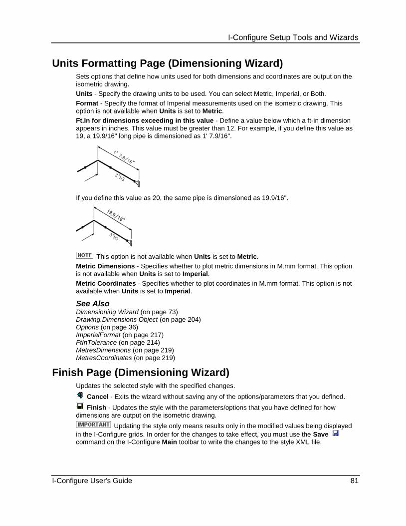
I-Configure Setup Tools and Wizards
I-Configure User's Guide 81
Units Formatting Page (Dimensioning Wizard) Sets options that define how units used for both dimensions and coordinates are output on the isometric drawing.
Units - Specify the drawing units to be used. You can select Metric, Imperial, or Both.
Format - Specify the format of Imperial measurements used on the isometric drawing. This option is not available when Units is set to Metric.
Ft.In for dimensions exceeding in this value - Define a value below which a ft-in dimension appears in inches. This value must be greater than 12. For example, if you define this value as 19, a 19.9/16" long pipe is dimensioned as 1' 7.9/16".
If you define this value as 20, the same pipe is dimensioned as 19.9/16".
This option is not available when Units is set to Metric.
Metric Dimensions - Specifies whether to plot metric dimensions in M.mm format. This option is not available when Units is set to Imperial.
Metric Coordinates - Specifies whether to plot coordinates in M.mm format. This option is not available when Units is set to Imperial.
See Also Dimensioning Wizard (on page 73) Drawing.Dimensions Object (on page 204) Options (on page 36) ImperialFormat (on page 217) FtInTolerance (on page 214) MetresDimensions (on page 219) MetresCoordinates (on page 219)
Finish Page (Dimensioning Wizard) Updates the selected style with the specified changes.
Cancel - Exits the wizard without saving any of the options/parameters that you defined.
Finish - Updates the style with the parameters/options that you have defined for how dimensions are output on the isometric drawing.
Updating the style only means results only in the modified values being displayed
in the I-Configure grids. In order for the changes to take effect, you must use the Save command on the I-Configure Main toolbar to write the changes to the style XML file.

I-Configure Setup Tools and Wizards
82 I-Configure User's Guide
Reports Wizard
Allows you to create and modify the report files generated by ISOGEN.
The reports selected apply only to the current style.
Reports Wizard Toolbar
The table below lists the commands that are available on the Reports Wizard toolbar.
Help - Opens the online user documentation delivered with the software and displays information about the wizard.
Cancel - Exits the wizard without saving any of the options/parameters that you defined.
Go back to previous step - Returns to the previous page of the wizard.
Go forward to next step - Proceeds to the next page of the wizard.
Finish - Saves the parameters/options that you have defined.
What do you want to do?
Add a report to a style (on page 82)
Remove a report from a style (on page 83)
Add a report to a style 1. Select a style in the Project View panel, such as Final-Basic
2. Click Reports Wizard on the Wizards toolbar. Alternatively, click Wizards > Reports Wizard.
The Wizards toolbar is located on the Overview panel.
3. Select the report you want to add to the current style in the Available report files list, and click >
The report is added to the Reports in current style list.
4. Click Go forward next step .
The Report Definition page appears.
5. Select the attribute you want included in the report, and click > to add it to the Attribute Definitions grid.
Use the CTRL key to select multiple attributes simultaneously.
6. Define the properties of the attribute as required.
When adding an attribute, the software uses a default width of 32 characters. You can edit this value to suit your project requirements. The software automatically adjusts the start position of the subsequent attribute accordingly.
7. Specify any additional output options, such as output path, if needed, and then click Go
forward next step .
For each report file you selected in step 3, a separate Report Definition page is displayed so that you can customize the report options.
8. Click Finish to update the style and close the wizard.

I-Configure Setup Tools and Wizards
I-Configure User's Guide 83
9. Click Save on the I-Configure Main toolbar to write the changes to the style XML file,
Remove a report from a style 1. Select the style in the Project View panel.
2. Click Reports Wizard on the Wizards toolbar Alternatively, click Wizards > Reports Wizard.
The Wizards toolbar is located on the Overview panel.
3. Select the report you want to remove in the Reports in the current style list, and click <.
The report is removed from the list.
4. Click Go forward next step as many times as needed to move to the Finish page.
5. Click Finish to update the style and close the wizard.
6. Click Save on the I-Configure Main toolbar to write the changes to the style XML file,
See Also
CutList.SummaryFile Object (on page 411)
WeldList.SummaryFile Object (on page 399)
Supplementary Object (on page 415)
Add a Report Page (Reports Wizard) Available Report Files - Lists the report files that are available.
Report Files in Current Style - Displays the names of the report files that are in the current style.
Report Definition Page (Reports Wizard)
A Reports Definition page displays for each report to be included in the style. For some reports, the content and layout is fixed. Only the location of the report can be user-defined.
Path - Specify the full path location for the report.
Delimited File - Specify whether the report file is to be delimited.
Generate Header - Specify whether the report file is to contain a header.
Available attributes - Select each attribute to be included in the report.
Attribute definitions - Define attribute properties as needed.
See Also Reports Wizard (on page 82)

I-Configure Setup Tools and Wizards
84 I-Configure User's Guide
Finish Page (Reports Wizard) Updates the selected style with the specified changes.
Cancel - Exits the wizard without saving any of the options/parameters that you defined.
Finish - Updates the style with the parameters/options that you have defined for how dimensions are output on the isometric drawing.
Updating the style only means results only in the modified values being displayed
in the I-Configure grids. In order for the changes to take effect, you must use the Save command on the I-Configure Main toolbar to write the changes to the style XML file.
See Also Reports Wizard (on page 82)

I-Configure Setup Tools and Wizards
I-Configure User's Guide 85
Detail Sketch Manager
Allows you to place parameters on the selected detail sketch so that correct relevant values, such as weld numbers, part number, and angles, are displayed on the isometric drawing.
Detail sketches are small, inserted drawings that provide additional details for components. The sketches are typically used to show more information about branch connections, support lugs, and special welds. To include detail sketches on your isometric drawing, you must first create symbols in a graphics package such as SmartSketch or AutoCAD. Then, use the I-Configure Detail Sketch Manager to view the detail sketch and specify options that control its various characteristics, such as the text formatting and placement. When you place the detail sketch in SmartPlant Isometrics or SmartPlant Spoolgen, the software prints a callout, or detail sketch identifier, next to the component if the user-supplied parameter is in the piping object data (POD) file. The detail sketch is then output on the isometric drawing. An example detail sketch is shown below.

I-Configure Setup Tools and Wizards
86 I-Configure User's Guide
The Detail Sketch Manager window consists of a toolbar (A), a list of available detail sketches (B), a viewing area (C), and a grid for data input (D).
A - Detail Sketch Manager Toolbar
Search - Filters the list of available detail sketches based on user-defined criteria. As you type into the Search box, the feature responds with an implied wild card at the beginning and at the end of the character string. For example, if you type B, the list of available sketches updates to display only those sketches with a B in the filename based on the defined criteria, *B*.
Add - Inserts a blank row at the bottom of the grid. You can also insert a row by clicking in the * row at the bottom of the grid.
Delete - Removes the currently selected row from the grid, as well as the detail sketch identifier, or box, that the data defined.
Zoom - Increases or decreases the display size of detail sketch objects in the viewing area. You can zoom in to get a closer view of an object, or zoom out to view more of the detail sketch at a reduced size. Click the left mouse button and drag the pointer upward in the window to increase the view of an object as though you were moving closer to it. Drag the pointer downward in the window to reduce the view as though you were moving further away from the object.
Zoom Area - Increases the view magnification of an area in the detail sketch that you define with two points.

I-Configure Setup Tools and Wizards
I-Configure User's Guide 87
Zoom All - Displays the entire detail sketch in the viewing area.
Pan - Repositions the detail sketch in the viewing area so that you can view another section of the sketch without changing the view magnification.
Style - Displays the style selected in the Project View panel in the I-Configure Main window. This option is read only.
OK - Prompts you to save any unsaved data. Click Yes to save the data in the grid to the current style and close the Detail Sketch Manager.
Cancel - Discards any unsaved data in the grid, and closes the Detail Sketch Manager.
Apply - Saves the data that has been defined in the grid for the current sketch, but leaves the Detail Sketch Manager open so that you can define parameters for another sketch.
B - Detail Sketch List
Displays the detail sketches that are available for the style selected in the I-Configure Project View panel. When you select a detail sketch in the list, a graphical view of the sketch displays in the detail sketch viewing area, as shown below.

I-Configure Setup Tools and Wizards
88 I-Configure User's Guide
When you open the Detail Sketch Manager, the software looks in the folder location defined by Supplementary.DetailSketches.Path and displays only those files types defined by Supplementary.DetailSketches.FileFormat. The example below shows the detail sketch folder path and file format that have been defined in I-Configure for the Final-Basic style.
In the current version of the software, only DWG, IGR, and SYM (SHA) file formats are fully supported.
You can use the Search box on the Detail Sketch Manager toolbar to narrow down the list of available sketches.
C - Detail Sketch Viewing Area
Displays a graphical view of the selected detail sketch. As you define parameters in the grid area, the viewing area updates the detail sketch to display a box at the selected XPos and YPos location on the sketch.

I-Configure Setup Tools and Wizards
I-Configure User's Guide 89
D - Grid Area
Allows you to position parameters directly onto the detail sketch. Parameters are derived from the component on which the detail sketch is placed. Each line of data in the grid displays a box at the selected X,Y location on the detail sketch. When you select a row in the grid, the corresponding detail sketch parameter box is considered active and displays as blue in the detail sketch viewing area. An inactive detail sketch parameter box displays as red. In the following example, the ANGLE row is selected in the grid, making the corresponding box active.
Parameter - Specifies the user-supplied detail sketch identifier.

I-Configure Setup Tools and Wizards
90 I-Configure User's Guide
Method - Specifies how the required data is to be extracted from the piping object data (POD) file for isometric drawing output. The following table lists the supported methods, along with any required input parameters.
Selected Method Required Input Parameter Description
Copy Enter any valid attribute or property of the component, its parent pipeline, or its material.
Returns the value of the specified property. This can include the part number, the weld number, or any other known property.
SectionAxis X Y
Returns the X- or Y-axis label.
The Y-axis label for a section through the component, based on the component HeaderOrientation property is as follows:
Vertical returns E (or as modified by ATEXT -248)
Horizontal returns U (-244)
Sloped/falling returns U (-244)
Non-orthogonal returns blank
The X-axis label for a section through the component, based on the component HeaderOrientation property is as follows:
Vertical returns S (-247)
Horizontal returns orthogonal vector to header and Up, E for N/S header, S for E/W header, compound direction otherwise.
Sloped/falling returns same as Horizontal
Non-orthogonal returns blank
SectionAngleFromClosestAxis
Specify a component property, such as BranchAngle, or attribute that contains an angle. For example, you can enter C.BranchAngle or C.COMPONENT-ATTRIBUTE1.
Converts the input angle, which is 0-360, to an angle based on the closest axis.
Angle = 0 to 45 returns angle
Angle = 45.1 to 89.9 returns (90 – angle)
Angle = 90 to 135 returns (angle – 90)
Angle = 135.1 to 179.9 returns (180 – angle)
Angle = 180 to 225 returns (angle – 180)
Angle = 225.1 to 269 returns (270 – angle)
Angle = 270 to 315 returns (angle – 270)
Angle = 315.1 to 359.9 returns (360 – angle)
Invalid input (not a number in the range 0-360) returns zero ( 0 )
MainWeldNumber N/A Returns the REPEAT-WELD-IDENTIFIER of the main (header) weld of an olet.
BranchWeldNumber N/A Returns the REPEAT-WELD-IDENTIFIER of the branch weld of an olet, set-on or tee.
SupportWeldNumber Enter 1-n. Returns the REPEAT-WELD-IDENTIFER of the nth support weld.

I-Configure Setup Tools and Wizards
I-Configure User's Guide 91
Selected Method Required Input Parameter Description
LugPartNumber Enter 1-n. Returns the REPEAT-PART-NUMBER of the nth lug
AdditionalMaterialPartNumber
Enter 1-n. Returns the REPEAT-PART-NUMBER of the nth additional material
Input - Defines the parameter required by the selected Method. Select a parameter from the list, or type the parameter directly into the box. For more information about methods and their associated input parameters, refer to the above table.
CharHeight - Defines the height of the character on the isometric drawing. It also sets the size of the box used to place text. The default setting is 3.
XPos - Defines the X-position of the detail sketch identifier relative to the bottom left corner of the detail sketch.
YPos - Defines the Y-position of the detail sketch identifier relative to the bottom left corner of the detail sketch.
Font - Specifies the type of font used to display text.
Justification - Defines the justification for the text. You can select Left, Centre, or Right.
Layer - Specifies the layer of the CAD file to use.
Colour - Specifies the index number that represents a specific colour as defined in the output drawing software.
Rotation - Defines the angle that text is allowed to be rotated in output.
Configure a Detail Sketch 1. Select a style in the Project View panel.
2. Click Detail Sketch Manager on the Wizards toolbar. Alternatively, click Wizards > Detail Sketch Manager.
3. In the Detail Sketch Manager window, select a detail sketch in the list.
To populate the list of detail sketches, the software uses the Supplementary.DetailSketches.FileFormat and Supplementary.DetailSketches.Path properties defined for the selected style. These two properties define the location of the detail sketch library and the file type (DWG, IGR, or SYM), respectively.
If necessary, use the Search feature on the Detail Sketch Manager toolbar to filter the detail sketches shown in the list.
The software displays a graphical view of the selected detail sketch in the detail sketch viewing area.

I-Configure Setup Tools and Wizards
92 I-Configure User's Guide
4. In the grid area, define detail sketch parameters as needed.
Use the XPos and YPos values to position the box in the detail sketch. Alternately, you can position the box interactively using the mouse. As you drag the box, the XPos and YPos values in the grid automatically update.
Each line of data in the grid displays a box at the selected X,Y location on the detail sketch. In the following example, three parameters have been defined.
5. Click OK on the Detail Sketch Manager toolbar to save the data to the current style and close the window.
To save the data to the current style and then work with another detail sketch, click Apply.
To add a blank row at the bottom of the grid, click Add or click the * row at the bottom of
the grid. To remove a row of data from the grid, click Delete .
See Also Detail Sketch Manager (on page 84)

I-Configure Setup Tools and Wizards
I-Configure User's Guide 93


I-Configure User's Guide 95
S E C T I O N 5
Opens the Project Defaults dialog box. Project defaults allow you to configure application-specific properties. On the Project Defaults tab, you can view the default properties that are available for the selected project. Because project defaults are application-specific, the application, or product, being used determines which properties are displayed and can be configured.
Attributes, though, are the same regardless of the application. Attributes can be set on a pipeline, component, weld, bolt, spool, or material basis. The Attributes tab allows you to view attribute values. When you double-click an attribute in the grid, the software opens the Attribute dialog box, in which you can edit those values. The Attributes tab also allows you to access the New Attribute dialog box so that you can create a new attribute.
Attribute Expressions
You can define an attribute as containing an expression that references other attributes in the same collection and can contain functions. The value of the attribute is then the result of evaluating the expression.
ATTRIBUTE1 = P-100-ABC
ATTRIBUTE2 = Left(“$ATTRIBUTE1$”,1) & Right(“$ATTRIBUTE1$”,3)
In the previous example, ATTRIBUTE2 contains an expression. Its value (as seen in the properties dialog box in the software) is reported as PABC (the left-most character plus the three right-hand characters from the string P-100-ABC).
A good analogy is a spreadsheet, where a cell can reference the contents of another cell and built-in spreadsheet functions. Cells can contain both values and formulas.
Attribute expressions are built and tested using the Evaluation expression option when defining an attribute on the Attribute and New Attribute dialog boxes. When creating an attribute expression, follow the expression building rules listed below.
References can be made only to other attributes in the same collection of attributes. That is, you cannot reference a pipeline attribute from a component.
References to other attributes are made using the $ATTRIBUTE_NAME$ syntax. The ATTRIBUTE_NAME must be the underlying unique name for the attribute, not the Display name setting on the Attributes tab (Project Defaults dialog box), which can be redefined by the user. The Expression Builder is used to help build correctly-defined expressions.
Expressions are evaluated using the VBScript engine. That is, the syntax of the attribute expression must be valid VBScript syntax and can contain any function supported by that language. If an expression cannot be evaluated, regardless of the reason, the value reported is the original expression.
ATTRIBUTE2 = Left(“$ATTRIBUTE1$”,1) :
ATTRIBUTE2 would display “P”
ATTRIBUTE2 = Lft(“$ATTRIBUTE1$”,1)
ATTRIBUTE2 would display “Lft(“$ATTRIBUTE1$”,1)”
[Lft is not a valid VBScript function]
Project Defaults and Attributes

Project Defaults and Attributes
96 I-Configure User's Guide
If the expression is expecting a string-- for example, the Left function takes a string value for its first argument--then the double quote (“) must be used around the attribute reference, whether or not the referenced attribute is defined as a string is irrelevant.
Valid - Left(“$ATTRIBUTE1$”,1)
Invalid - Left($ATTRIBUTE1$,1)
The attribute containing the expression must be defined as a string. All the piping object data file (POD) user-specified attributes (ATTRIBUTE1..ATTRIBUTE200, COMPONENT-ATTRIBUTE1..COMPONENT-ATTRIBUTE10) are suitable for use as expressions.
Project Defaults Dialog Box (on page 101)
Attribute Dialog Box (on page 108)
Build Expression Dialog Box (on page 109)
New Attribute Dialog Box (on page 109)
What do you want to do?
Add a new attribute (on page 96)
Edit an attribute (on page 97)
Delete an attribute (on page 98)
Import PipeHeader attributes (on page 98)
Create an attribute expression (on page 98)
Add a new attribute
1. Click Project Defaults . Alternatively, click Edit > Project Defaults.
The Project Defaults dialog box appears.
2. Click the Attributes tab.
3. Click New.
The New Attribute dialog box (on page 109) appears.
4. Use the Isogen attribute list to select the attribute you want to add.

Project Defaults and Attributes
I-Configure User's Guide 97
Isogen attribute is the name used in the PCF.
5. Define the remaining attribute values as required, and then click OK.
The new attribute is displayed in its group on the Attributes tab of the Project Defaults dialog box.
To specify that the attribute contains an expression, you must select Evaluate expression. You can type an attribute expression directly into the Default value box, or click Build to open the Build Expression dialog box (on page 109).
Edit an attribute
1. Click Project Defaults . Alternatively, click Edit > Project Defaults.
The Project Defaults dialog box (on page 101) appears.
2. Click the Attributes tab.
3. Double-click the attribute you want to edit.
The Attribute dialog box (on page 108) appears.
4. Edit the data as needed, and then click OK.
To specify that the attribute contains an expression, you must select Evaluate expression. You can type an attribute expression directly into the Default value box, or click Build to open the Build Expression dialog box (on page 109).

Project Defaults and Attributes
98 I-Configure User's Guide
Delete an attribute
1. Click Project Defaults . Alternatively, click Edit > Projects.
The Project Defaults dialog box (on page 101) appears.
2. Click the Attributes tab.
3. Select the attribute you want to delete, and click Remove.
You can only delete user-specified attributes.
Remove is available only when a user-specified attribute is selected.
Import PipeHeader attributes You can import project attributes from the PIPEHEADER-ATTRIBUTES section of a DDF or from the Personal ISOGEN PIP file used in Project Manager (PipMan) projects.
1. Click Project Defaults and then click the Attributes tab.
2. Click Import on the Attributes tab.
3. In the Browse for Project Data dialog box, select the required input file format from the Files of type list.
4. Navigate to the required file, select it, and then click Open to import.
If the Pipe Header attributes are imported, use care when using the External Pipeline attributes file.
Create an attribute expression 1. Do one of the following;
a. Add a new attribute (on page 96), and select Evaluate expression.
b. Edit an attribute (on page 97), and select Evaluate expression.
2. Click Build.
The Build Expression dialog box appears.

Project Defaults and Attributes
I-Configure User's Guide 99
3. To add an attribute reference, double-click the required attribute in the Attributes list.
The attribute is inserted in the Expression edit box. In the example below, Pipeline Reference has been added.
4. To add a function reference, double-click the required function in the Functions list.
The function is inserted in the Expression edit box at the cursor position.
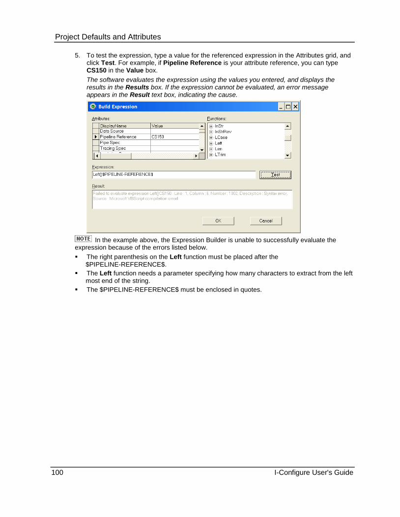
Project Defaults and Attributes
100 I-Configure User's Guide
5. To test the expression, type a value for the referenced expression in the Attributes grid, and click Test. For example, if Pipeline Reference is your attribute reference, you can type CS150 in the Value box.
The software evaluates the expression using the values you entered, and displays the results in the Results box. If the expression cannot be evaluated, an error message appears in the Result text box, indicating the cause.
In the example above, the Expression Builder is unable to successfully evaluate the expression because of the errors listed below.
The right parenthesis on the Left function must be placed after the $PIPELINE-REFERENCE$.
The Left function needs a parameter specifying how many characters to extract from the left most end of the string.
The $PIPELINE-REFERENCE$ must be enclosed in quotes.

Project Defaults and Attributes
I-Configure User's Guide 101
When you correct the syntax, as shown in the example below, and re-run Expression Builder the result is C, the left-most character from the string CS150.
The Attribute Editor control (AttributeEditor.ocx, 1.4 or later) supports the editing of expressions (using the Expression Builder defined in the previous section). Clicking an attribute that contains an expression displays the standard edit button:
When you click , the software displays the Expression Builder. The dialog box is populated with current values of the attributes. Operation of the dialog box is the same as described in the previous sections.
Editing an expression in SmartPlant Spoolgen only affects the current POD file. In order to change the expression for all future POD files in the project, the expression must be changed in I-Configure project defaults as previously described.
See Also Isometric Projects (on page 117) Project Defaults and Attributes (on page 95) Attributes Tab (Project Defaults Dialog Box) (on page 102)

Project Defaults and Attributes
102 I-Configure User's Guide
Project Defaults Dialog Box Displays information about attributes and application-specific properties.
Project Defaults Tab (Project Defaults Dialog Box) (on page 102)
Attributes Tab (Project Defaults Dialog Box) (on page 102)
Project Defaults Tab (Project Defaults Dialog Box) You can modify any project default as needed. Some properties are typed entries: click once in the Value box to place the cursor, and then type the required value. Other properties display a Browse arrow ( ) when you click in the Value box. In some instances, clicking opens a dialog box in which you can navigate to and select the required file. In other instances, clicking
displays a selection list from which you can select the required value.
Application (on page 102)
Project defaults are product-specific.
In the case of the default application, such as I-Run, no project defaults are displayed.
See Also Attributes Tab (Project Defaults Dialog Box) (on page 102) ProjectConfig_<Application Name>.xml (on page 31)
Application
Specifies the software product to which the project defaults apply.
Attributes Tab (Project Defaults Dialog Box) Lists the names of and default values for system and user-specified attributes. You can edit values to be taken by system attributes, such as Pipe Spec, Revision, and so on. To edit attribute values, double-click the attribute to open the Attribute dialog box.
Context - Organizes the attribute groups listed below.
Pipeline Attributes (on page 104)
Component Attributes (on page 106)
Weld Attributes (on page 106)
Bolt Attributes (on page 106)
Spool Attributes (on page 107)
Material Attributes (on page 108)
Display Name - Shows the attribute name that is displayed in the application. .
Default Value - Displays the value that is used if the value within the application is not change, depending on the Set Value setting.
Allowable Values - Displays the allowable values that are available for the attribute. These are the values that display in the software, as shown in the example below.

Project Defaults and Attributes
I-Configure User's Guide 103
Isogen Attribute - Specifies which ISOGEN attribute is to be used. This option is available only for user-specified attributes (ATTRIBUTE1 to ATTRIBUTE199). For system attributes, this option is read only.
Attributes 1 to 99 map to ISOGEN -601 to -699. For example, ATTRIBUTE95 maps to ISOGEN -695.
Attributes 100 to 199 map to ISOGEN attribute -900 to -999. For example, ATTRIBUTE101 maps to ISOGEN attribute -901.
Source - Indicates whether the attribute is a System or User attribute.
Set Value -Controls how the value is set.
ISOGEN - No Default Value is defined. The attribute cannot be modified.
ISOGEN then Default - Use the value defined in the ISOGEN input file. If no value is set, use the Default Value setting.
Default - Sets the value to what is defined by the Default Value setting.
Units - Displays the type of units, such as inches or kilograms, and is only available for attributes that contain a measurement or weight.
Visible - Controls whether the attribute can be seen in the application.
Editable - Controls whether the attribute can be modified.
Expression - Indicates whether the attribute contains an expression. For more information about attribute expressions, see Attribute Expressions in Project Defaults and Attributes (on page 95).
Build - Opens the Build Expression dialog box (on page 109) in which you can use the Expression Builder to create and test the attribute expression. This option is available only when Evaluate expression is selected.
You can type an attribute expression directly in the Default value box instead of using the Expression Builder.
Import - Allows you to import attribute data from an external source.
New - Opens the New Attribute dialog box in which you can create a new user-specified attribute.
Remove - Deletes the selected attribute. You can only delete user-specified attributes.
See Also Project Defaults and Attributes (on page 95) Add a New Attribute (on page 96) Edit an Attribute (on page 97) Delete an Attribute (on page 98)

Project Defaults and Attributes
104 I-Configure User's Guide
Pipeline Attributes
Displays the attributes that are specific to a pipeline. Pipeline attribute values can be output to the isometric drawing (A) and to report files (B).
Pipeline Header Attribute Description
AREA data Identifies part of a project.
ATTRIBUTE1 data to ATTRIBUTE199 data
Provides up to 199 user-specified pipe header attributes that can be used for any purpose.
BATCH data Identifies part of a project.
BEND-RADIUS data Standard pulled bend radius.
DATE-DMY data D=Day M=Month Y=Year, such as 21/09/99. Specify in any order.
HIGHEST-ASSEMBLY-NUMBER data Highest Assembly Number generated on the previous run of the pipeline.
HIGHEST-PART-NUMBER data Highest Material List Part Number generated on the previous run of the pipeline.
HIGHEST-SPOOL-NUMBER data Highest Spool Number generated on the previous run of the pipeline.
HIGHEST-SUPPORT-WELD-NUMBER data Highest Pipe Support Weld Number generated on the previous run of the pipeline.
HIGHEST-UNIQUE-PART-IDENTIFIER data Highest Unique Part Identifier generated on the previous run of the pipeline.
HIGHEST-WELD-NUMBER data Highest Weld Number generated on the previous run of the pipeline.
INSULATION-SPEC data Insulation Spec reference.
ITEM-ATTRIBUTE0 data to ITEM-ATTRIBUTE9 data
Provides up to 10 User defined material Attributes for use where component material descriptions are broken down into a series of short elements where data is defined in dynamic keywords like MATL RATING SPEC THKS etc. This provides an alternative method to having a single long material description in a component DESCRIPTION attribute.
MISC-SPEC1 data User defined Miscellaneous Specification Reference.

Project Defaults and Attributes
I-Configure User's Guide 105
Pipeline Header Attribute Description
MISC-SPEC2 data User defined Miscellaneous Specification Reference.
MISC-SPEC3 data User defined Miscellaneous Specification Reference.
MISC-SPEC4 data User defined Miscellaneous Specification Reference.
MISC-SPEC5 data User defined Miscellaneous Specification Reference.
NOMINAL-CLASS data Identifies pipeline design class.
NOMINAL-RATING data Identifies pipeline design class.
OFFSET-IMPERIAL data Offset in feet from Datum point.
OFFSET-METRIC data Offset in metres from Datum point.
OUTPUT-FILE-NAME data Name to be used for drawing output file.
PAINTING-SPEC data Painting specification.
PIPELINE-REFERENCE data Pipeline name.
PIPELINE-TEMP data Pipeline operating temperature.
PIPELINE-TYPE data Type of Pipeline construction.
PIPING-SPEC data Pipeline specification reference.
PROJECT-IDENTIFIER data Project number or name.
REPLOT Single isometric re-plot request.
REVISION data Revision identifier.
SPECIFIC-GRAVITY data Specific gravity of pipeline contents.
SPOOL-PREFIX data Prefix to be used on spool identifiers.
START-CO-ORDS data Indicator to ensure IDF is generated with same start point on re- plot.
SUPPORT-WELD-PREFIX-ERECTION data Prefix to be used for the identification of all erection pipe support welds.
SUPPORT-WELD-PREFIX-FABRICATION data Prefix to be used for the identification of all fabrication pipe support welds.
SUPPORT-WELD-PREFIX-OFFSHORE data Prefix to be used for the identification of all offshore pipe support welds.
SYSTEM-ISOMETRIC-REFERENCE data System isometric name.
TRACING-SPEC data Tracing specification reference.
WELD-PREFIX-ERECTION data Prefix to be used for the identification of all erection welds.
WELD-PREFIX-FABRICATION data Prefix to be used for the identification of all fabrication welds
WELD-PREFIX-GENERAL data General prefix to be used for the identification of all welds.
WELD-PREFIX-OFFSHORE data Prefix to be used for the identification of all offshore welds.
See Also Add a New Attribute (on page 96) Attributes Tab (Project Defaults Dialog Box) (on page 102) Project Defaults and Attributes (on page 95)

Project Defaults and Attributes
106 I-Configure User's Guide
Component Attributes
Displays all of the attributes currently allowed for components in I-Configure. Component attributes are similar to pipeline attributes in terms of configuration but are specific to components (valves, pipe, flanges, and so forth). The values for component attributes are typically output to the bill of materials on the isometric drawing and the material report file.
ISOGEN supports a set of attributes that are available for all components, including a set of 10 user-definable ones. In addition, certain components have specific attributes. For example, a valve has a SPINDLE-DIRECTION attribute not used by other components.
The table below shows the ISOGEN user-specified attributes:
Pipeline Data File Format Attributes
IDF –190 to -199 records
PCF COMPONENT-ATTRIBUTE1 to COMPONENT- ATTRIBUTE10
See Also Add a New Attribute (on page 96) Attributes Tab (Project Defaults Dialog Box) (on page 102) Project Defaults and Attributes (on page 95)
Weld Attributes
Displays all of the attributes currently allowed for welds in I-Configure.
ISOGEN supports a set of attributes that are available for all welds, including a set of 10 user-definable attributes. Some weld attributes can be output to the isometric drawing in special weld enclosures.
They can also be output to the weld list on the isometric drawing and the welding report files.
Weld attributes are attached to welds in the 3D design system model, and it is recommended that you refer to your Design System Administrator for information on how to set them up. They are then passed to ISOGEN in extracted Piping Data files, either in IDF or PCF format.
The table below lists the ISOGEN user-specified attributes:
Pipeline Data File Format Attributes
IDF –180 to -189 records
PCF WELD-ATTRIBUTE1 to WELD- ATTRIBUTE10
See Also Add a New Attribute (on page 96) Attributes Tab (Project Defaults Dialog Box) (on page 102) Project Defaults and Attributes (on page 95)

Project Defaults and Attributes
I-Configure User's Guide 107
Bolt Attributes
This tab shows all the attributes currently allowed for bolts in I-Configure.
ISOGEN supports a set of attributes that are available for all bolts, including a set of 10 user-definable attributes.
The following table lists the ISOGEN user-specified attributes:
Pipeline Data File Format Attributes
IDF –190 to -199 records
PCF ASSEMBLY-ATTRIBUTE1 to ASSEMBLY- ATTRIBUTE10
In the case of bolts, ASSEMBLY-ATTRIBUTES are not included in the tab, but can be
added clicking .
See Also Add a New Attribute (on page 96) Attributes Tab (Project Defaults Dialog Box) (on page 102) Project Defaults and Attributes (on page 95)
Spool Attributes
This tab shows all the attributes currently allowed for Spools in I-Configure.
The following table lists the ISOGEN user-specified attributes:
Pipeline Data File Format Attributes
-28
IDF -91 record
-170 to -179 record
PCF SPOOL-IDENTIFIER SPOL-DRAWING-SEQUENCE- NUMBER SPOOL-ATTRIBUTE1 to SPOOL-ATTRIBUTE10
See Also Add a New Attribute (on page 96) Attributes Tab (Project Defaults Dialog Box) (on page 102) Project Defaults and Attributes (on page 95)

Project Defaults and Attributes
108 I-Configure User's Guide
Material Attributes
This tab shows all the attributes currently allowed for materials in I-Configure. The following table lists ISOGEN user-specified attributes:
Pipeline Data File Format Attributes
IDF -80 to -89 records
PCF MATERIAL-ATTRIBUTE1 to MATERIAL-ATTRIBUTE10
See Also Add a New Attribute (on page 96) Attributes Tab (Project Defaults Dialog Box) (on page 102) Project Defaults and Attributes (on page 95)
Attribute Dialog Box Displays the values that are currently defined for the selected attribute. Depending on the attribute and its current settings, many of the values in this dialog box can be modified to suit requirements of your project.
Display Name - Shows the attribute name that is displayed in the application. .
Allowable Values - Displays the allowable values that are available for the attribute. These are the values that display in the software, as shown in the example below.
Default Value - Displays the value that is used if the value within the application is not change, depending on the Set Value setting.
Make attribute visible - Indicates whether the attribute can be seen in the application.
Allow edits - Indicates whether the attribute can be modified.
Evaluate expression - Indicates whether the attribute contains an expression. For more information about attribute expressions, see Attribute Expressions in Project Defaults and Attributes (on page 95).
Build - Opens the Build Expression dialog box in which you can use the Expression Builder to create and test the attribute expression. This option is available only when Evaluate expression is selected.
You can type an attribute expression directly in the Default value box instead of using the Expression Builder.
Units - Displays the type of units, such as inches or kilograms, and is only available for attributes that contain a measurement or weight. Set Value -Controls how the value is set.
ISOGEN - No Default Value is defined. The attribute cannot be modified.
ISOGEN then Default - Use the value defined in the ISOGEN input file. If no value is set, use the Default Value setting.
Default - Sets the value to what is defined by the Default Value setting.

Project Defaults and Attributes
I-Configure User's Guide 109
Isogen Attribute - Specifies which ISOGEN attribute is to be used. This option is available only for user-specified attributes (ATTRIBUTE1 to ATTRIBUTE199). For system attributes, this option is read only.
Attributes 1 to 99 map to ISOGEN -601 to -699. For example, ATTRIBUTE95 maps to ISOGEN -695.
Attributes 100 to 199 map to ISOGEN attribute -900 to -999. For example, ATTRIBUTE101 maps to ISOGEN attribute -901.
See Also Edit an attribute (on page 97)
Build Expression Dialog Box Sets options for adding a new attribute reference.
Attributes - Lists all available (defined) attributes. To add a new attribute reference, double-click the row containing the attribute you wish to add.
Functions - Lists the functions that can be executed as part of the expression. To add a function reference, select a function from the tree view on the right-hand side of the Expression Builder, and then double-click it.
Expression - Displays the attribute expression.
Test - Evaluates the attribute expression to determine if an errors are present.
Result - Displays the results of the test.
See Also Create an Attribute Expression (on page 98)
New Attribute Dialog Box Sets options for new user-specified attributes.
Display name - Enter the name of the attribute as you want it to display in the application.
You can also use this option in external data configuration. For more information, see Attach External Data.
Allowable values - Specify the values that are available for the attribute in the software. Enter the values delimited by a semi-colon. For example, if you enter 0;1;2;3;4;5, the values display as shown in the example below.
Default value - Specify the default value for the attribute. The default value is used if the value in the application is not changed, depending on the Set Value setting.
Make attribute visible - Specify whether the attribute can be seen in the application.
Allow edits - Specify whether the attribute can be modified.
Evaluate expression - Specify whether the attribute contains an expression. For more information about attribute expressions, see Attribute Expressions in Project Defaults and Attributes (on page 95).

Project Defaults and Attributes
110 I-Configure User's Guide
Build - Opens the Build Expression dialog box in which you can use the Expression Builder to create and test an attribute expression. This option is available only when you select Expression.
You can type an attribute expression directly in the Default value box instead of using the Expression Builder.
Units - Specify the units that are applicable to the attribute, if required
Set Value - Select one of the options below. This option is only available if a value is defined for Default value.
ISOGEN then Default - Use the value in the ISOGEN input file if one exists. Otherwise, use the Default Value setting.
Default - Use the Default Value setting for the attribute regardless of whether a value is defined in the ISOGEN input file.
Isogen attribute - Select the ISOGEN attribute to which the data field is mapped.
Attributes 1 to 99 map to ISOGEN -601 to -699. For example, ATTRIBUTE95 maps to ISOGEN -695.
Attributes 100 to 199 map to ISOGEN attribute -900 to -999. For example, ATTRIBUTE101 maps to ISOGEN attribute -901.
OK - Creates the attribute with the settings you have defined, closes the dialog box and returns to the Attributes tab. The new attribute is added to the bottom of the list displayed on the Attributes tab.
Cancel - Closes the dialog box and returns to the Attributes tab without creating the new attribute.
Apply - Creates the attribute with the settings you have defined. The New Attribute dialog box remains open so that you can define another new attribute.
See Also Add a new attribute (on page 96)

Project Defaults and Attributes
I-Configure User's Guide 111


I-Configure User's Guide 113
S E C T I O N 6
In I-Configure, the isometric directory is folder that has been designated as a container for projects. An isometric directory can contain multiple projects. The isometric directory can be located anywhere, including on a network drive.
Isometric Directory Object Properties (on page 115)
What do you want to do?
Create a new isometric directory (on page 113)
Delete an isometric directory (on page 114)
Copy and paste an isometric directory (on page 114)
Connect to an isometric directory (on page 113)
Disconnect from an isometric directory (on page 115)
Create a new isometric directory
1. Click New Isometric Directory . Alternatively, click File > New > Isometric Directory.
The Browse for Folder dialog box appears.
2. Double-click the drive or specify the network path in which you want to create the new isometric directory.
3. Click New Folder.
4. Enter the name of the new isometric directory and the then click OK.
The new isometric directory appears in the Project View panel.
Isometric directory object properties are shown in the Properties panel .
After you create an isometric directory, you must next create a new isometric project (on page 118) to hold styles.
If you select the No Projects level in the Project View panel, Create New Project is unavailable.
In order to create a project, you must first select the isometric directory.
On Windows NT4 systems, New Folder does not appear on the Create Isometric Directory dialog box. Use Windows Explorer to create a folder with the required isometric directory name before selecting this as the isometric directory to be used.
Isometric Directories

Isometric Directories
114 I-Configure User's Guide
Connect to an isometric directory Adds an existing (usually remote) isometric directory, without creating the isometric directory folder.
1. Click File > Connect to Isometric Directory. Alternatively, click Connect to Isometric
Directory .
The Connect to Isometric Directory dialog box appears.
2. Navigate to the C:\SampleIsoDir\Project List.xml file, and click Open.
The isometric directory is displayed in the Project View panel.
Whether a mapped drive or full UNC path is shown is dependent on options (on page 36) set for the project.
Delete an isometric directory Deleting a remote isometric directory only removes the reference to it from the Project View panel, the folder is not deleted.
You cannot delete remote project and style folders.
1. In the Project View panel, click the isometric directory you want to delete.
2. Click Delete . Alternatively, click Edit > Delete, or right-click the isometric directory in the Project View panel and then click Delete.
Deleting an isometric directory cannot be undone.
Copy and paste an isometric directory 1. In the Project View panel, click the isometric directory you want to copy.
2. Click Copy . Alternatively, click Edit > Copy, or right-click the isometric directory and then click Copy.
3. With the isometric directory still selected, click Paste . Alternatively, click Edit > Paste, or right-click the isometric directory and then click Paste.
The Browse for Folder dialog box appears.
4. Double-click the drive or specify a network path on which the copied (new) isometric directory is to be placed.
5. Click New Folder, and specify the name of the pasted (new) isometric directory.
Isometric directories that exist on the same drive cannot have the same name.
6. Click OK.
The Project View panel updates to show the newly pasted isometric directory, including all the projects and styles that were part of the original isometric directory.

Isometric Directories
I-Configure User's Guide 115
Disconnect from an isometric directory Removes an isometric directory from the Project View panel. Deleting a remote isometric directory only removes the reference to it from the Project View panel, it does not delete the folder. You cannot delete remote projects and style folders.
1. In the Project View panel, select the isometric directory you want to remove.
2. Click File > Disconnect Isometric Directory. Alternatively, click Disconnect Isometric
Directory .
The isometric directory disappears from the Project View panel.
See Also Project View Panel (on page 20) Isometric Directory Object Properties (on page 115)
Isometric Directory Object Properties The properties for each isometric directory are stored in their own object. When you select an isometric directory in the Project View panel, the Properties panel updates to show its corresponding object properties. In the example below, the Properties panel is displaying the object properties of the SampleIsoDir isometric directory.
Path - Displays the isometric directory folder file path. This information is read-only and cannot be modified.
Name - Displays the isometric directory folder name. This information is read-only and cannot be modified.
ChangeIsoDirList - Specifies whether you can add or delete isometric directories to and from the global list. If set to True, adding and deleting isometric directories is allowed. If there is no write access to the IsoDirList.xml (on page 31) file, the property value is set to False, and no add/delete functions can be completed.
See Also Isometric Project Object Properties (on page 128) Isometric Drawing Style Object Properties (on page 149) Create a New Isometric Directory (on page 113) Copy and Paste an Isometric Directory (on page 114) Delete an Isometric Directory (on page 114)

Isometric Directories
116 I-Configure User's Guide

I-Configure User's Guide 117
S E C T I O N 7
An isometric project represents a set of isometric drawing styles and associated data that are used by ISOGEN to create specific types of isometric drawings. Isometric generation software logs into the project. When you initially create an isometric project, it is application-specific, meaning that it is to be used a specific product. This is because different applications require that different isometric drawing styles to be available, as is determined by the type of isometric drawings and report deliverables the application is required to produce. For example, SmartPlant Isometrics provides as-designed or as-built piping isometric drawings, whereas SmartPlant Spoolgen produces isometric drawings that are suitable for pipe fabrication in the shop and construction of the spools on-site.
Network Projects
You can set up isometric projects on a network server so that multiple client workstations can concurrently access and share project configurationsy.
For a description of mapped drives and UNC paths for network projects, see Options (on page 36).
For more information about connecting to network isometric directory and associated projects, see Connect to an Isometric Directory (on page 113).
Access Rights
You can control access to any I-Configure project. Access rights can be password protected. The first person to set the access rights is able to set a password to prevent others from modifying it. An isometric project can then be set up so that others can see and use it but cannot save changes to the project or to any of the isometric drawing styles in the project.
New Project Dialog Box (on page 121)
Enable Project Dialog Box (on page 122)
Project Access Rights Dialog Box (on page 122)
What do you want to do?
Create a new isometric project (on page 118)
Define project access rights (on page 119)
Set up an isometric project on a network server (on page 119)
Connect to a network isometric project (on page 120)
Enable an isometric project (on page 120)
Delete an isometric project (on page 121)
Copy and paste an isometric project (on page 121)
Isometric Projects

Isometric Projects
118 I-Configure User's Guide
Isometric Project Common Tasks The following tasks are frequently used when you create a new isometric project.
Create New Isometric Projects
The isometric drawing styles used by ISOGEN to create specific types of drawings are contained within projects. You can create a stand-alone isometric project that supports only a single user or an isometric project that exists in a network configuration that can be accessed by multiple users simultaneously. For more information, see Create a new isometric project (on page 118) and Set up an isometric project on a network server (on page 119).
Import Data from External Sources
You can import isometric projects from several external sources. When you import an isometric project, it is shown immediately in the project view panel. For more information, see Import Isometric Projects (on page 123).
Backup Isometric Project Data
You can save an isometric project and its associated references to external files in a single folder. In addition, you can also choose to include any existing output files such as drawings and reports, in the backup. For more information, see Backup Isometric Projects (on page 122).
Create a new isometric project 1. Do one of the following:
Create a new isometric directory (on page 113)
Select an existing isometric directory in the Project View panel.
2. Click Create New Project . Alternatively, click File > New > Project.
The New Project dialog box (on page 121) appears.
3. Type a name for the new isometric project in the New Project Name box.
4. In the Application list, select the name of the product to which the new isometric project applies.
5. In the Available Styles list, select the drawing styles required for the new isometric project.
You can include and exclude a drawing style by selecting and clearing its check box. By default, all drawing styles that are suitable for use with the selected product are shown as selected. To exclude a style, clear its check box.
6. Click OK.
The software creates the isometric project and its associated drawing styles, and displays it in the Project View panel.
An isometric project must be created for use with a specific product. However, it is possible to enable a project for use with other products.
The isometric drawing styles that display in the Available Styles list depend on the product that is selected in the Application list.
When you create an isometric project for SmartPlant Spoolgen, you must also initialize the project attributes by specifying the value for the Project ID Type.

Isometric Projects
I-Configure User's Guide 119
Define project access rights 1. Select a project in the Project View panel, and click Tools > Project Access Rights.
The Project Access Rights dialog box (on page 122) appears.
2. Set the access rights for the selected project.
3. If needed, type a password.
To avoid situations where the isometric project cannot be modified, such as when the password is forgotten, ensure that you make a note of the password used for each project. It is the responsibility of each individual or Project Administrator to ensure that any password protection used to secure projects or styles against unwanted modification are backed up or made note of in accordance with the data loss prevention and protection policy of your company.
4. Click OK.
After a password is set, the access rights cannot be changed unless the correct password is entered.
If the access rights are set to Write, everyone working in the isometric project is allowed to save changes to the associated drawing styles and export the isometric drawing style settings. If set to Read Only, everyone working in the project can make changes, but the changes cannot be saved or exported.
When you set project access rights to Write using a valid password, any existing password is cleared.
Set up an isometric project on a network server
1. Create a new isometric directory (on page 113).
2. Create a new isometric project (on page 118) and its associated drawing styles.
To avoid file conflict errors, it is also necessary to change the output path for the message file for each isometric drawing style in the project configuration, so that the file is written locally, for example to C:\TEMP, when users attempt to use the same style concurrently. ISOGEN then outputs the message file it creates to this local folder instead of to the same folder on the network server.
3. Use Windows Explorer to create the Message file path, such as C:\TEMP, if one does not exist.
4. For each isometric drawing style in the project, add an item to a collection to the ISOGENFiles collection in the Supplementary.ReportFiles object. This definition sets the path to C:\Local Folder Name\Message Filename. In the example below, the file path to the Message file is defined as C:\TEMP\Spool.mes.
You can use the Reports wizard (on page 82) to set the message file path.
Use an appropriate filename for the message file, such as Spool.mes for the Spool style.
Set the drive on which the isometric directory and isometric project to be connected to resides to be shared, and set the required permissions for the share.

Isometric Projects
120 I-Configure User's Guide
Connect to a network isometric project
1. Click Create Isometric Directory .
2. In the Browse for Folder dialog box, browse to the network path where the isometric directory to be connected to resides, select the isometric project, and then click OK.
The project appears in the Project View panel.
Enable an isometric project You can enable existing isometric projects to work with other products installed on the same workstation. For example, a project initially created for I-Run can also be enabled to work with SmartPlant Isometrics. For more information, see the Enable Isometirc Project Matrix below.
Default SmartPlant Isometrics
SmartPlant Isometrics I-Tools
SmartPlant Spoolgen
Default N Y Y Y
SmartPlant Isometrics Y N Y Y
SmartPlant Isometrics I-Tools Y Y N Y
SmartPlant Spoolgen Y Y Y N
1. Select the isometric project you want to enable in the Project View panel.
2. Click Enable Project . Alternatively, click File > Enable Project.
The Enable Project dialog box (on page 122) appears.
3. Select the application that the isometric project is to be enabled for in the Application list.
4. Specify the isometric drawing styles required by the project. You include and exclude drawing styles by selecting and clearing the check boxes.
The isometric project cannot be re-enabled for itself. In other words, the application that the project was first created for is not shown in the list.
Some isometric drawing styles are considered mandatory and some optional. For example, SmartPlant Spoolgen requires the SGImport.xml and Spool.xml drawing style files. As such, these are considered mandatory styles. Mandatory drawing styles cannot be unselected.

Isometric Projects
I-Configure User's Guide 121
Delete an isometric project
Deleting a project cannot be undone.
1. In the Project View panel, select the isometric project you want to delete.
2. Click Delete . Alternatively, click Edit > Delete, or right-click the isometric project in the Project View panel and then click Delete.
Copy and paste an isometric project 1. In the Project View panel, select the isometric project you want to copy.
2. Click Copy . Alternatively, click Edit > Copy, or right-click the project and then click Copy on the shortcut menu.
3. In the Project View panel, select the isometric directory in which you want to paste the project.
4. Click Paste .
The isometric project and all of its associated drawing styles are pasted into the selected isometric directory.
You can repeat steps 1-4 to copy and paste multiple isometric projects.
New Project Dialog Box Sets options for creating a new isometric project.
Current isometric directory - Displays the name of the current isometric directory. This setting is read only.
New project name - Type the name of the new isometric project.
Application - Select the name of the application with which the new isometric project is to be used.
Available styles - Lists the isometric drawing styles that are currently available. By default, all drawing styles that are suitable for use with the selected product are shown as selected. If a style is not required, clear its check box so that it is excluded when the isometric project is created.
Type - Indicates whether the isometric drawing style is Optional or Mandatory. Use the check boxes to select or clear an isometric drawing style from the isometric project.
Name - Displays the name of the isometric drawing style.
Template - Displays the name of the template XML file on which the drawing style is based.
OK - Creates the isometric project using the settings you have defined.
Cancel - Closes the dialog box with creating the isometric project.
See Also Create a New Isometric Project (on page 118)

Isometric Projects
122 I-Configure User's Guide
Enable Project Dialog Box Sets options for enabling isometric projects to work with other applications that are installed on the same workstation.
Application - Select the application for which you want to enable the isometric project.
Type - Indicates whether the isometric drawing style is optional or mandatory. An optional style can be added to or removed from the project by selecting and clearing its check box. You cannot remove a mandatory drawing style from the project.
Name - Displays the name of the isometric drawing style.
Template - Displays the name of the template XML file that contains the isometric drawing style configuration data. Template files are delivered to the $Program Files$\Common Files\Intergraph\I-Configure folder.
See Also Enable an Isometric Project (on page 120) <Style Name>.xml (on page 34)
Project Access Rights Dialog Box Sets options for defining access to an isometric project.
Project access rights - Specifies the level of access. Select Write or Read-only.
Password - Assigns a password to the isometric project.
See Also Define Project Access Rights (on page 119)
Backup Isometric Projects You can save selected isometric projects and their associated references to external files in a single folder. In addition, you can also choose to include any existing output files such as drawings and reports, in the backup. After the information is saved, you can restore that version of the isometric project and its associated data in the event of system failure. The Backup Project command is also used to permit the sending of isometric project data to another location.
Backup Project Dialog Box (on page 123)
Create a backup of an isometric project 1. Select an isometric project in the Project View panel, and click Tools > Backup Project.
You can also select an isometric drawing style in the Project View panel that belongs to the project you want to backup.
The Backup Project dialog box (on page 123) displays.
2. Click the browse button , navigate to the folder in which the backup is to be saved, and click OK.
The software displays the full path location and folder name in the Specify folder for backup box.
3. Modify the settings as needed.

Isometric Projects
I-Configure User's Guide 123
The Include Project data and Include external data options are selected by default. If there are any existing drawings or reports within the selected project's drawing styles that you want included in the backup, select Include existing Style outputs (Drawings and Reports).
4. Click OK.
When the backup is complete, the software displays an informational message.
5. Click OK to close the message box.
Backup Project Dialog Box Sets options for backing up the selected isometric project.
Specify folder for backup - Type the full path location to the folder that contains the isometric project that you want to back up.
Include Project data - Includes all project level files as part of the backup. This includes the SmartPlant Spoolgen workflow database and any SmartPlant Isometrics POD files. This is the default setting.
Include external data - Includes any external file that is referenced from the isometric project as part of the backup. This is the default setting.
Include existing Style outputs (Drawings and Reports) - Includes any drawings and reports that currently exist within any of the drawing styles associated with the selected isometric project as part of the backup.
OK - Starts the backup process. This option is available only when a valid location is specified in the Specify folder for backup box.
Cancel - Closes the dialog box without backing up the isometric project.
See Also Create a Backup of an Isometric Project (on page 122)

Isometric Projects
124 I-Configure User's Guide
Import Isometric Projects You can import an existing PipMan, Spoolgen 4 or I-Configure-based projects into I-Configure. You can also import an I-Configure XML backup file. When you import an I-Configure project from backup, you are essentially restoring a previously backed up version of an isometric project, including any external data referenced in the project and all project level files, such as the SmartPlant Spoolgen workflow database and any SmartPlant Isometrics POD files. This feature is useful for situations when you are moving projects and styles from one location to another.
After the import is complete, the imported project appears in the Project View panel. You can edit an imported project and modify its properties in the same manner as with an isometric project that you create using I-Configure.
PipMan and Spoolgen 4 projects must be imported into I-Configure before they can be used with any other product that uses I-Configure to create and manage projects and styles.
Import of isometric project and isometric drawing style settings is intelligent. If an isometric project folder is replicated, meaning that there is a common structure apart from the drive, then the software modifies the path in the needed style (OPT or FLS) so that it points to the referenced file in its new location. For example, if you copy a project folder from G:\M5000 to C:\Users\Data\CompanyName\MP4000, the software identifies the common root as MP4000. Any file referenced from an OPT file in this path will have its path modified. Using the previous example, the software modifies the G:\MP4000\Data\CPT.fdf file to the C:\Users\Data\CompanyName\MP4000\Data\CPT.fdf file, presuming that this file exists.
Import Project Dialog Box (on page 126)
Import Project from Backup Dialog Box (on page 127)
What do you want to do?
Import a PipMan project (on page 124)
Import a Spoolgen 4 project (on page 125)
Import an I-Configure-based project (on page 125)
Import an isometric project from backup (on page 126)

Isometric Projects
I-Configure User's Guide 125
Import a PipMan project 1. Create a new isometric directory (on page 113) in I-Configure.
2. Click Tools > Import Project > From File.
The Import Project dialog box (on page 126) appears.
3. Click the browse button , navigate to the *.pip file for the PipMan project to be imported, and click OK.
The software displays the full path location and file name in the Import settings from box.
4. Type a name for the isometric project in the New project name box.
5. Specify the required import options, and then click OK.
The New Project dialog box (on page 121) appears.
6. Select the application to which the isometric project applies in the Application list.
7. Click OK.
8. If required, click Yes to view the log file; otherwise, click No.
Until they're imported, PipMan projects are always shown in magenta in the Project View panel.
After import, the original PipMan project remains on the drive as a backup copy.
Import a Spoolgen 4 project 1. Create a new isometric directory (on page 113) in I-Configure.
2. Click Tools > Import Project > From File.
The Import Project dialog box (on page 126) appears.
3. Click the browse button , navigate to the *.ini file for the Spoolgen 4 project to be imported, and click OK.
The software displays the full path location and file name in the Import settings from box.
4. Type a name for the isometric project in the New project name box.
5. Define the required import options, and then click OK.
The New Project dialog box (on page 121) appears.
6. Select the application to which the isometric project belongs in the Application list, and then click OK.
7. If necessary, click Yes to view the log file; otherwise, click No.
Existing Spoolgen 4 projects are not shown in the Project View panel.
The imported Spoolgen 4 project is only available for use with Spoolgen 5.
After import, the original Spoolgen 4 project remains on the drive as a backup copy.
Import an I-Configure-based project When you import an I-Configure project, you must select a Project_Data.xml (on page 31) file. By default, the project settings (project defaults, attributes) and data (all files in the source project folder) are copied to the new isometric project. Optionally, you can suppress the copying of data files leaving the new isometric project with the identical structure as the old one but empty.

Isometric Projects
126 I-Configure User's Guide
1. Create a new isometric directory (on page 113).
2. Click Tools > Import Project > From File.
The Import Project dialog box (on page 126) appears.
3. Click the browse button , navigate to the *_Data.xml file for the I-Configure-based project to be imported, and click OK.
The software displays the full path location and XML file name in the Import settings from box.
4. Type a name for the isometric project in the New project name box.
5. Do one of the following:
a. Click OK to accept the defaults.
b. Select Import Project settings only if only the project settings are to be imported, and then click OK.
The isometric project and all associated isometric drawing styles, including any existing drawing and report files and all files in the source project folder, are copied to the new isometric project. If you selected Import Project settings only, only the drawing style XML files are imported. Previously generated drawing and report files are not imported.
Import an isometric project from backup 1. In the Project View panel, select an isometric directory, project, or style.
2. Click Tools > Import Project > From Backup.
The Import Project from Backup dialog box (on page 127) appears.
3. Click the browse button , navigate to the folder that contains the backup XML file that you want to restore, and click OK.
The software displays the full path location and file name in the Path to project backup box. The software also updates the dialog box to display all mandatory and optional drawing styles that exist within the isometric project to be restored.
4. If the isometric project being restored already exists on the target machine, specify whether you want the existing project to be replaced or updated.
5. Use the Select Optional Styles to restore check boxes to indicate which optional drawing styles are to be restored with the isometric project.
6. Click OK.
When the import is complete, the software displays an informational message.
7. Click OK to close the message box.
The Project View panel displays the restored isometric project, including all restored isometric drawing styles.
See Also ProjectConfig_<Application Name>.xml (on page 31) AccessRights (on page 132) LockedBy (on page 133) Project View Panel (on page 20) Project Defaults and Attributes (on page 95) Tutorial Project (on page 30)

Isometric Projects
I-Configure User's Guide 127
Import Project Dialog Box Sets options for importing isometric projects into I-Configure.
Import settings from - Specifies the isometric project settings to be imported. In the Files of type list, select the file type to be imported. Support file types are listed below.
Project Type File Type
PipMan *.pip
Spoolgen 4 *.ini
I-Configure *_Data.xml
The import options listed below only display after you have specified the project settings to be imported.
New project name - Type a name for the isometric project. This is what displays in the Project View panel.
Preserve all current style control files and mark as Never Export - This option is available only when you import a PipMan or Spoolgen 4 project.
Import Project settings only - Imports only the isometric project settings, which includes the isometric drawing style XML files. However, previously generated drawing and report files are excluded from the import. This option is available only when you import an I-Configure-based isometric project.
See Also Import Isometric Projects (on page 123)
Import Project from Backup Dialog Box Sets options for restoring an isometric project from a backup.
Path to Project backup - Type the full path location and filename of the backup isometric project XML file to be restored.
Replace the existing Project - Deletes the contents of the existing isometric project and replaces with the contents of the backup, resulting in a new isometric project. This option is not available if an existing project with the same name does not exist on the target machine.
Update the existing Project - Overwrites the existing isometric project with the backup data. This option maintains the existing folder structure. Project files (or drawing styles) with the same name are updated. Files that are contained within the existing isometric project, but are not part of the backup, are untouched.
Keep backup of the current Project data - Restores the isometric project and simultaneously copies the existing isometric project to a new folder named Project_Backup_n, where Project is the name of the isometric project and n indicates the revision number of the backup, as in PipingProj_Backup_1, PipingProj_Backup_2, and so on. This is the default setting.
Mandatory Styles - Lists the mandatory isometric drawing styles that exist in the project to be restored. This option is read only.
Select Optional Styles to restore - Lists the optional isometric drawing styles that exist in the project to be restored. To include an optional style, select its check box. To exclude an optional style, clear its check box.
OK - Restores the isometric project.
Cancel - Closes the dialog box without restoring the isometric project.

Isometric Projects
128 I-Configure User's Guide
Isometric Project Object Properties The properties for each isometric project are stored in their own object. These properties are read-only and cannot be modified. When you select an isometric project in the Project View panel, the software updates the Properties panel to display the properties specific to the selected project. In the example below, the Properties panel shows the properties that have been defined for the Piping_Project1 project.
Name (on page 129)
Path (on page 129)
Source (on page 129)
AppList (on page 129)
AppCount (on page 130)
WeldGaps (on page 130)
ElbowConversion (on page 131)
ChangeStyleList (on page 132)
AccessRights (on page 132)
SystemXML (on page 132)
ProjectXML (on page 132)
LockedBy (on page 133)
IsoDirectoryName (on page 133)
SystemMaterialManagerXML (on page 133)
ProjectMaterialManagerXML (on page 133)
SystemMaterialDataXML (on page 133)
ProjectMaterialDataXML (on page 133)

Isometric Projects
I-Configure User's Guide 129
Name Specifies the project folder name.
Path Displays the path to the project folder. The project folder contains all of the styles that have been defined for the project.
Source Displays the vendor-specific string that was defined when the project was created. For example, a project created by an Intergraph product, such as SmartPlant Isometrics, has the Source set to Intergraph. The Source string is controlled by the SetSource method as described in the ProjectConfig_<application name>.xml (on page 31) file.
The Source property allows a vendor to judge whether its software can use the project, and allows you to identify which projects are created by which vendor software products.
Some products, such as SmartPlant Isometrics and SmartPlant Spoolgen, can share a project.
This is a read only property and cannot be modified.
See Also Create a New Isometric Project (on page 118) Enable an Isometric Project (on page 120)
AppList Displays the names of the enabled products in a semi-colon delimited list, such as Spoolgen;SP Isometrics.

Isometric Projects
130 I-Configure User's Guide
AppCount Displays the number of software products enabled on the project.
See Also Enable an Isometric Project (on page 120)
WeldGaps Displays an XML-formatted text string, which defines the rules for ISOGEN to allow for weld gaps, weld shrinkage, connection gaps, and connection insertion lengths, when dimensioning and adjusting cut piece lengths.
Initially the WeldGaps property value is empty. To populate, double-click the property value box and then click File > Update in the WeldGaps window.
If any data is present in the WeldGaps property, you can set the UseWeldGapData property on the MaterialList.CutList object to True so that data is written to the ISOGEN Welding Definition (WDF) file.
When you import a style, if the WDF file contains a WELD-GAPS entry, both the WeldGaps and MaterialList.CutList.UseWeldGapData properties are set to True.
See Also CutList Object (on page 402) Import Isometric Drawing Style Settings from File (on page 146) UseWeldGapData (on page 405)

Isometric Projects
I-Configure User's Guide 131
ElbowConversion Displays an XML-format text string. This property defines the rules for the following:
Conversion of elbows to pulled bends.
Cut length adjustments that ISOGEN makes to the length of cut pieces to allow for extra lengths of pipe to satisfy the requirements of particular bending machines.
If any data is present in the ElbowConversion property, it is used for converting elbows to bends. Also, if data is present, then all styles that output cut list information must set the UseTangentData property on the MaterialList CutList object to True to make sure that the cut list values are correct.
Initially, the ElbowConversion property value is empty. Double-click the property value box and then click File > Update in the ElbowConversion window.
When you import a style, if the Data Definition (DDF) file contains a STANDARD-BEND-LENGTHS entry, the ElbowConversion and MaterialList.CutList.UseTangentData properties are both set to True. The example below shows a section of a DDF file with a STANDARD-BEND-LENGTHS entry.
See Also CutList Object (on page 402) Import Drawing Style Settings from File (on page 146) UseTangentData (on page 406)

Isometric Projects
132 I-Configure User's Guide
ChangeStyleList Controls whether you can add styles to and delete styles from the project. If set to True, you can add and delete styles. If there is no write access to the ProjectList.xml file in the isometric directory on a network project, ChangeListStyle is set to False, which prohibits all add/delete functions.
If AccessRights is set to ReadOnly, the ChangeStyleList property is also set to False.
See Also AccessRights (on page 132) ProjectList.xml (on page 34) Set up an Isometric Project on a Network Server (on page 119)
AccessRights Indicates the level of access to the project. You can set AccessRights to Write or ReadOnly.
To change the access rights on a project, you must use the Project Access Rights command. For more information, see Define project access rights.
You can lock the style files against unwanted modification in two ways:
1. Set the file system access control on the style XML file or style folder.
2. Set a password in the Project Access Rights dialog box.
The style CanWrite and CanExport properties indicate whether you have rights to save the style or export the style to ISOGEN control files.
The AccessRights property is set to ReadOnly if you do not have write access to the Project_data.xml file in the project folder. In this case, no changes can be saved to project properties.
See Also CanExport (on page 151) CanWrite (on page 151) LockedBy (on page 133) Set up an Isometric Project on a Network Server (on page 119)
SystemXML Displays the path to the SystemPOD.xml configuration file.
This is a system file, and its contents should not be modified.
ProjectXML Displays the path to the PipelineProject.xml file. This configuration file contains the user-specified extensions to pipeline, component, weld and bolt attributes that have been defined for the project.

Isometric Projects
I-Configure User's Guide 133
LockedBy Displays the name of the individual who locked the project, presuming that AccessRights is set to ReadOnly. Otherwise, the property is blank.
See Also AccessRights (on page 132) Define Project Access Rights (on page 119)
IsoDirectoryName Specifies the name of the isometric directory that contains the current project. An isometric directory can contain multiple projects. This information is read-only and cannot be modified.
SystemMaterialManagerXML Displays the path to the SystemMaterialManager.xml configuration file.
This is a system file, and its contents should not be modified.
ProjectMaterialManagerXML Displays the path to the ProjectMaterialManager.xml file. This configuration file contains user-specified materials and attributes.
SystemMaterialDataXML Displays the path to the SystemMaterialData.xml configuration file.
This is a system file, and its contents should not be modified.
ProjectMaterialDataXML Displays the path to the ProjectMaterialData.xml file. This configuration file contains user-specified information regarding the components that are used in the ProjectPipeline.xml and ProjectMaterialManager.xml configuration files.


I-Configure User's Guide 135
S E C T I O N 8
An isometric drawing style contains a group of object properties that control some aspect of the drawings and reports that are produced by I-Configure. Collectively, these drawing styles contain all the properties necessary to control ISOGEN, resulting in a set of drawings and report files. The way that you configure styles determines what the isometric drawing looks like when it is generated and what information is included on a report. Multiple drawing styles can exist side-by-side to produce different outputs from the same design file.
Each isometric drawing style has its own set of object properties that are stored in an XML file named <Style Name>.xml. During isometric drawing generation, the contents of this XML file are converted into the set of text control files that are read by ISOGEN.
I-Configure includes a set of template XML files that you can use as a starting point for defining isometric drawing styles to meet your specific requirements. After you configure a user-defined drawing style, it can be used as a template for future projects. For more information, see Sample Files (on page 34).
During a default installation of the software, the isometric drawing style template XML files are delivered to the <Installation Drive>:\Program Files\Common Files\Intergraph\I-Configure\Templates folder.
Drawing Preview
The Preview Drawing command exports the current isometric drawing style and runs ISOGEN on a standard Piping Component File (PCF) to create an isometric drawing. You can then view the drawing to see the effect of the current style settings on the isometric drawing output. The default drawing output is DWG. If ISOGEN encounters any errors during drawing generation, they are written to a message file, which you can also view.
New Style Dialog Box (on page 142)
Drawing Preview Dialog Box (on page 143)
What do you want to do?
Create a new isometric drawing style (on page 136)
Select an isometric drawing style (on page 137)
View ISOGEN controls (on page 137)
Copy and paste an isometric drawing style (on page 139)
Delete an isometric drawing style (on page 140)
Save an isometric drawing style (on page 141)
Preview the drawing (on page 141)
See Also Import and Export Style Settings (on page 144) Backup Isometric Style Settings (on page 143)
Isometric Drawing Styles

Isometric Drawing Styles
136 I-Configure User's Guide
Isometric Drawing Style Common Tasks The following tasks are frequently used when you create a new isometric drawing style.
Create New Isometric Styles
You can add a new isometric drawing style that is based on any one of the template files that are delivered with the product. For more information, see Create a new isometric drawing style (on page 136).
Import Data from External Sources
You can import drawing styles into an isometric project from several external sources. When you import an isometric drawing style, it is shown immediately in the Project View panel. For more information, see Import and Export Style Settings (on page 144).
Develop the Look and Feel of Drawings
You can change the look and feel of an isometric drawing by changing the drawing style properties that appear in the Detail panel. Style object properties can specify everything from drawing content to the system controls for output definition. For more information, see Appendix: Isometric Drawing Style Objects (on page 167).
Use Alternative Text
AText is an abbreviation for alternative text, an ISOGEN feature that allows you to change or remove any text on the isometric drawing. You can substitute your own text in place of standard ISOGEN words. For more information, see Alternative Text Object (on page 173).
Configure the Material List
You can specify three different styles for the material lists that are plotted on the isometric drawing. For more information, see Drawing Setup Tool (on page 37).
Create a new isometric drawing style
New isometric drawing styles are based on one of the templates that are delivered with I-Configure.
1. Do one of the following:
a. Create a new isometric directory and project.
Create a new isometric directory (on page 113)
Create a new isometric project (on page 118)
b. Select an existing isometric project in the Project View panel.
2. Click New Style . Alternatively, click File > New > Style.
The New Style dialog box (on page 142) appears.
3. Select the product to which the isometric drawing style applies in the Application list.
The software displays all the template styles that are available for the selected product.
4. Clear the check boxes of the XML style templates that you do not want to create, and ensure any required XML style template is selected.
5. Double-click the Name box of the selected isometric drawing style, highlight the existing style name, and then type the new style name.

Isometric Drawing Styles
I-Configure User's Guide 137
6. Click OK.
The software displays the new isometric drawing style under the selected isometric project in the Project View panel.
You can edit the properties of the new style as required. For more information, see Detail Panel (on page 26).
If you leave all style templates checked, and click OK, any existing styles with the same name under the selected project are duplicated, and _1 is appended to the style name. For example, Final-Basic becomes Final-Basic_1.
Before a style can be used, it must first be exported. When you export a style, a variety of control files that ISOGEN requires to process isometric drawings and reports, such as *.opl, *.pos, *.alt, or *.fls files, are created based on the settings made for the style. For more information, see Export isometric drawing style settings (on page 147).
You can also create styles when a new project is created.
Select an isometric drawing style In the Project View pane, select an isometric drawing style in the tree view.
As in Windows Explorer, you can click and to expand and close the nodes in the tree view.
You can use the Style objects in the Detail panel to modify the selected isometric drawing style.
View ISOGEN controls 1. Select an isometric drawing style in the Project View panel, and click Tools > View
ISOGEN Controls.
The View ISOGEN Controls dialog box appears, allowing you to preview the ISOGEN settings for the selected style. The example below lists the configuration files for the Final-Basic style.

Isometric Drawing Styles
138 I-Configure User's Guide
2. To view the contents of a configuration file, double-click it.
The software opens it using your default text editor. The example below shows the contents of the Final-Basic Drawing Definition (DDF) file.
3. To close the file, click File > Cancel.
4. Click OK to close the dialog box.

Isometric Drawing Styles
I-Configure User's Guide 139
Copy and paste an isometric drawing style
1. In the Project View panel, select an isometric drawing style and then click Copy . Alternatively, click Edit > Copy, or right-click the style and then select Copy in the shortcut menu.
2. Click Paste . Alternatively, click Edit > Paste, or right-click in the Project Panel and then click Paste.
The New Style Name dialog box appears.

Isometric Drawing Styles
140 I-Configure User's Guide
3. Type a name for the new style in the New style name box, and click OK.
The software displays a default name based on the style being copied.
The software creates a copy of the style and adds it to the styles listed in the Project View panel, as shown in the example below. The properties of the original style are persisted to the new style.

Isometric Drawing Styles
I-Configure User's Guide 141
Delete an isometric drawing style
Deleting a drawing style cannot be undone.
1. In the Project View panel, select the isometric drawing style that you want to delete.
2. Click Delete .Alternatively, click Edit > Delete, or right-click the style name in the Project View panel, and click Delete.
Save an isometric drawing style Before any changes that you make to an isometric drawing style can be used, you must first save the updated style.
Click Save . Alternatively, click File > Save.
The software saves the current I-Configure settings to the <Style Name>.xml file. This is a necessary step before any new settings become available in the application being used.
Preview the drawing 1. Select the isometric drawing style in the Project View panel, and click Preview Drawing
on the toolbar. Alternatively, click Tools > Preview Drawing.
ISOGEN processes the data. When processing completes, I-Configure opens the Isogen Preview dialog box.

Isometric Drawing Styles
142 I-Configure User's Guide
2. Select the file you want to view in the Files generated list, and click View.
If you select DRAWING in the File Type list, the software opens up the drawing in the View window on the Basic Setup page. An example is shown below.
If you select MESSAGE or MATERIAL, the software opens the file using the default text editor.
3. Click Close to return to I-Configure window.
The default drawing output is DWG.
To view any errors reported by ISOGEN, open the message file.
New Style Dialog Box Sets options for a new isometric drawing style.
Application - Associates the isometric drawing style with an application. Select an application in the list.
Optional styles - Lists all of the template styles that are currently available. Use the check boxes to indicate on which template XML file the new isometric drawing style is to be based.

Isometric Drawing Styles
I-Configure User's Guide 143
Drawing Preview Dialog Box Isogen returned - Displays any errors that ISOGEN encountered during the isometric generation process.
Files generated - List all of the files output by the generation process.
View - Displays the contents of the selected file. Report files are opened using a default text editor, such as Notepad.
Close - Closes the dialog box.

Isometric Drawing Styles
144 I-Configure User's Guide
Backup Isometric Style Settings You can save selected isometric drawing styles and their associated references to external files, such as the backing sheet, in a single folder. In addition, you can also choose to include any drawing style-related output files, such as drawings and reports, in the backup. After the isometric drawing style settings are saved, you can restore that version of the style and its associated data in the event of system failure. The Backup Style command is also used to permit the sending of isometric drawing style settings to another location.
Backup Style Dialog Box (on page 144)
Create a backup of an isometric drawing style 1. Select an isometric drawing style in the Project View panel, and click Tools > Backup
Style.
The Backup Project dialog box (on page 123) displays.
2. Click Browse , and navigate to the folder in which the backup is to be saved.
3. Modify the options as needed.
Include external data is selected by default. If there are any drawings or reports within the selected drawing style that you want included in the backup, select Include existing Style outputs (Drawings and Reports).
4. Click OK.
When the backup is complete, the software displays an informational message.
5. Click OK to close the message box.
Backup Style Dialog Box Sets options for backing up the selected isometric drawing style settings.
Specify folder for backup - Enter the full path location to the folder that contains the isometric drawing style that you want to back up.
Include external data - Includes references to external files, such as backing sheets, as part of the backup. This is the default setting.
Include existing Style outputs (Drawings and Reports) - Includes any drawings and reports that currently exist within the selected isometric drawing style as part of the backup.
OK - Starts the backup process. This option is available only when a valid location is specified in the Specify folder for backup box.
Cancel - Closes the dialog box without backing up the isometric drawing style.

Isometric Drawing Styles
I-Configure User's Guide 145
Import and Export Style Settings You are not limited to using only the style XML templates that are delivered with the software. I-Configure allows you to import isometric drawing styles into an isometric project from the sources listed below.
I-Configure XML style file
Personal ISOGEN FLS file
SPOOLGEN®
OPT file
PDS®
ISOGEN DEF file
Alias .IDF file
I-Configure XML backup file
When you import an I-Configure XML backup file, you are essentially restoring a previously backed up version of an isometric drawing style's settings, including any external data referenced in the project. This feature is useful for situations you are moving projects and styles from one location to another.
You can also import isometric drawing style fragments into the current style. A style fragment is contained in an XML file that specifies a set of properties to be set and/or a set of members for a collection object, such as a set of TextColumns to be used with MaterialList.SummaryFile object.
Before an isometric drawing style can be used, it must first be exported. When you export a drawing style, a variety of control files that ISOGEN requires to process isometric drawings and reports (*.opl, *.pos, *.alt, *.fls), are created based on the settings made for the style.
Import Style Dialog Box (on page 147)
Import Style from Backup Dialog Box (on page 148)
What do you want to do?
Import isometric drawing style settings from file (on page 146)
Import isometric drawing style settings from backup (on page 146)
Import an isometric drawing style fragment (on page 147)
Export isometric drawing style settings (on page 147)
Export an isometric drawing style fragment (on page 147)

Isometric Drawing Styles
146 I-Configure User's Guide
Import isometric drawing style settings from file 1. In the Project View panel, select the isometric project in which you want to import the
isometric drawing style settings.
2. Click Tools > Import Style.
The Import Style dialog box appears.
3. Click Browse and navigate to the XML file whose style settings you want to import.
The Select Style Settings to Import dialog box appears.
If you know the full path location and file name of the style XML file, enter it in the Import settings from box instead of using the browse feature
4. Select the file type, navigate to the required file, and then click Open.
5. In the Import Style dialog box, specify the required import options, and then click OK.
Depending on the current status of the styles within the project, do one of the following:
If the isometric drawing style being imported does not exist in the isometric project, select Create a new style.
If the isometric drawing style already exists within the isometric project but is to be used as a basis for another new drawing style, select Create a new style, and type a name for the new style.
If the isometric drawing style already exists in the isometric project, and you want its settings to be overwritten, clear the Clear style first checkbox, and select Import into the current style.
To import into an existing style but clear the contents of the style first, select Import into the current style and Clear style first checkbox.
The isometric drawing style is imported. You have an opportunity to view a log file created during the import process.
After import, the drawing style becomes available under the isometric project into which is was imported and is shown in the Project View panel
Import isometric drawing style settings from backup 1. In the Project View panel, select an isometric project.
2. Click Tools > Import Style > From Backup.
The Import Style from Backup dialog box (on page 148) appears.
3. Click the browse button , navigate to the folder that contains the backup drawing style XML file that you want to restore, and click OK.
The software displays the full path location and file name in the Path to Style backup box.
4. If the isometric drawing style being restored already exists on the target machine, specify whether you want the existing style settings to be replaced or updated.
If the isometric drawing style to be restored does not exist on the target machine, and you do not want the software to create a backup of the current style data, clear the Keep backup of the current Style data check box.
5. Click OK.
When the restore is complete, the software displays an informational message.

Isometric Drawing Styles
I-Configure User's Guide 147
6. Click OK to close the message box.
The Project View panel displays the restored isometric drawing style under the selected isometric project.
Import an isometric drawing style fragment 1. In the Project View panel, select the isometric drawing style to which the style fragment
applies, such as Final-Basic.
2. Click Tools > Import Style Fragment.
3. Browse to the XML file for the style fragment, and then click Open.
I-Configure reads the content of the style fragment XML file and applies the new properties to the isometric drawing style.
If a style fragment file exists in the same folder as a template file, with the same name and with an .xml extension, it is automatically loaded. This allows the setting of properties specific to the template XML file, such as margins and list locations.
Export isometric drawing style settings
Click Export Style . Alternatively, click File > Export.
The software writes the settings to the <Style Name>.xml file.
This is not a required procedure because the products perform it for automatically before running ISOGEN.
The Export command is useful for debugging and, if the ExportBehaviour (on page 150) property for the style is set to Never Export, allows the style to be manually modified.
Export an isometric drawing style fragment 1. In the Project View panel, select the isometric drawing style to which the style fragment
applies, such as Final-Basic.
2. Click Tools > Export Style Fragment.
The Export Style Fragment dialog box appears.
3. Navigate to the required style fragment file, and click Save.
I-Configure reads the content of the drawing style and creates an XML file.
Import Style Dialog Box Sets options for importing isometric drawing styles from supported sources.
Import settings from - Type the name and full path location to the isometric drawing style file
whose settings you want to import. Alternatively, click Browse and use the Select Style Settings to Import dialog box to navigate to the style file you want to import.
Create a new style - Creates a new isometric drawing style based on the settings of the file you import. Use this option if the drawing style being imported does not exist in the project.
Import into current style - Overwrites the settings in the existing isometric drawing style file with those in the imported style file. The isometric drawing style must already exist in the isometric project.
Clear style first - Erases the contents of the existing style file and replaces them with the contents of the imported style file.

Isometric Drawing Styles
148 I-Configure User's Guide
Import Style from Backup Dialog Box Sets options for restoring a previously saved I-Configure XML backup file.
Path to Style backup - Type the full path location and filename of the backup isometric drawing style XML file to be restored.
Replace the existing Style - Deletes the settings of the existing isometric drawing style and replaces with the settings of the backup, creating a new isometric drawing style. This option is not available if an existing style with the same name does not exist on the target machine.
Update the existing Style - Overwrites the existing isometric drawing style settings with the backup data. Isometric drawing styles with the same name are updated. Any settings within the existing style that are not part of the backup are untouched.
Keep backup of the current Style data - Restores the isometric drawing style and simultaneously copies the existing style to a new folder named Style_Backup_n, where Style is the name of the isometric drawing style and n indicates the revision number of the backup, as in Final-Basic_Backup_1, Final-Basic_Backup_2, and so on. This is the default setting.
OK - Restores the isometric drawing style.
Cancel - Closes the dialog box without restoring the isometric drawing style.
See Also Import and Export Style Settings (on page 144)

Isometric Drawing Styles
I-Configure User's Guide 149
Isometric Drawing Style Object Properties When you select an isometric drawing style in the Project View panel, the software updates the Properties panel to display those properties that are specific to it. In the example below, the Properties panel is showing the default object properties that are defined for the Final-Basic style.
You can modify any of the properties as needed to satisfy your project requirements. Some object properties have a selection list that displays when the Value box is double-clicked. Other object properties are typed entries: click once in the Value box to place the cursor, and type the required value.
Name (on page 150)
Path (on page 150)
ExportBehaviour (on page 150)
StyleState (on page 150)
StyleType (on page 150)
ProjectName (on page 150)
Options (on page 151)
CanWrite (on page 151)
CanExport (on page 151)
See Also Isometric Directory Object Properties (on page 115) Isometric Project Object Properties (on page 128)

Isometric Drawing Styles
150 I-Configure User's Guide
Name Displays the name of the current isometric drawing style.
Path Displays the file path to the <Style Name> folder. The Options (OPL) file and the Data Definition (DDF) file are located in the <Style Name> folder.
ExportBehaviour Controls the behavior of the File > Export command.
Always Export - Export the Style object property to the ISOGEN control files.
Export if Pending - Export the Style object property only exported if the StyleState property is defined as Export Pending or Export and Save Pending.
Never Export - Suppress export of the Style object property.
See Also Export Isometric Drawing Style Settings (on page 147) StyleState (on page 150)
StyleState Reports whether the isometric drawing style has been changed. If it has been changed, StyleState also indicates whether the change has been saved and/or exported since the last change was made. This property is read only.
Unchanged - No changes have been made.
Export Pending - Changes have been saved but not exported.
Save Pending - Changes have been exported but not saved.
Export and Save Pending - Changes have not been saved or exported.
StyleType Indicates whether the isometric drawing style is a system style, such as the special purpose SGImport Style (used by SmartPlant Spoolgen) or a general purpose user style. The property is read only and has no effect on I-Configure behavior.
ProjectName Displays the name of the isometric project to which the selected isometric drawing style belongs.

Isometric Drawing Styles
I-Configure User's Guide 151
Options Supplements the properties delivered with I-Configure to include properties specific to SmartPlant 3D.
CanWrite Controls whether the changes can be written back to the <Style Name>.xml file. To do so requires write access to the <Style Name>.xml file. By default, the CanWrite property is set to False if the project AccessRights property is set to Read.
See Also AccessRights (on page 132) <Style Name>.xml (on page 34)
CanExport Controls whether the isometric drawing style can be exported. Exporting a style requires write access to the style folder.
See Also Export Isometric Drawing Style Settings (on page 147)


I-Configure User's Guide 153
S E C T I O N 9
In This Section Fonts in Isometric Drawings .......................................................... 153 Output a bar code on the isometric drawing .................................. 157 Add the barcode font to an AutoCAD backing sheet ..................... 158 Bends ............................................................................................. 159 Elbows ........................................................................................... 159 Weld Lists ...................................................................................... 159 Weld Logic ..................................................................................... 160 Weld Constructions ........................................................................ 161
Fonts in Isometric Drawings You can change the font that appears on the isometric drawing. A font information file (.fif), which contains a default collection of fonts, is delivered in the workstation setup in the [Product Folder]\Drawings\3rdParty\Alias\ProjectManager\Data folder.
On a 64-bit computer, this file is delivered to the [Installation Drive]\Program Files (x86)\Common Files\Alias\Data folder.
The full path location and filename of the ISOGEN font information file is specified by the Supplementary.Fonts object (on page 457). The software reads the contents of the file and displays a list of fonts that are available for the material list and the drawing.
If there is a requirement to use a font that is not available in the standard font information file delivered in the workstation setup, the software supports user-specified dynamic fonts. ISOGEN recognizes the font definition automatically during isometric drawing generation.
What do you want to do?
Select a font for isometric drawing output (on page 154)
Define a dynamic font for isometric drawing generation (on page 154)
Techniques

Techniques
154 I-Configure User's Guide
Select a font for isometric drawing output 1. Select an isometric drawing style in the Project View panel.
2. In the Detail panel, expand the Drawing node and click Format.
The Properties panel displays the Drawing.Format properties.
3. Locate TextFont in the Properties list, and double-click the Value box.
A list of font styles appears.
4. Select the required font style in the list.
Define a dynamic font for isometric drawing generation 1. Select an isometric drawing style in the Project View panel.
2. In the Detail panel, expand the Drawing and Dynamic Fonts nodes and click Fonts.

Techniques
I-Configure User's Guide 155
The Properties panel displays the properties for the Drawing.DynamicFonts Fonts collection.
3. Click Add to Collection .
The software inserts a blank row in the Properties panel.
4. Define the options as needed. In the example below, the Calibri font is being defined as a dynamic font.
You must define FontNumber and FontName. For more information about these properties, see Drawing.DynamicFonts Fonts Collection (on page 290).

Techniques
156 I-Configure User's Guide
5. Click Save to save the changes to the selected drawing style's XML file. You must have write permissions to the active isometric project to save changes to isometric drawing styles.
After the font is saved to the style XML file, it appears in the list of available text fonts for thos isometric drawing style objects that have a TextFont property. Two examples are shown below.
Figure 1: Drawing.Format.TextFont Property
Figure 2: MaterialList.TextFont Property

Techniques
I-Configure User's Guide 157
Output a bar code on the isometric drawing To output a bar code on the isometric, such as the example show below for the pipeline reference, you must create an attribute.
1. In the DFAttributes collection, create an attribute:
2. Set the following properties as indicated:
3. AttributeName (on page 485) to Pipeline Reference.
4. BarCode (on page 336) to one of the valid codes (1,2 or 3).
5. CharHeight (on page 485) to appropriate value.
6. Font (on page 485) to the font that matches the bar code value (Bar Code 39, Bar Code 25, Bar Code 25 Interleaved).
7. XPos (on page 485) to the X position for start of bar code.
8. YPos (on page 485) to the Y position for the start of bar code.
The required bar code must be installed in your system fonts directory.
For AutoCAD users, the backing sheet must have the bar code font defined in it.
See Also Supplementary.TableAttributes DFTableAttributes Collection (on page 484)

Techniques
158 I-Configure User's Guide
Add the barcode font to an AutoCAD backing sheet 1. Open the DWG, or DXF file, and add a new text style using the guidelines listed below.
2. In the Style Name list, set the style name to the name of the font file without the extension. In the example above, this is Bar39.ttf.
You must ensure that the style name matches the filename specified in the ISOGEN font information file (Fontstd.fif).
ISOGEN-FONT 151
FAMILY T
DESCRIPTION Bar Code 39
FILENAME BAR39.ttf
3. Select the required font name in the Font Name list to the required font. In the example above, this is Bar Code 39.
4. Click Apply, and then click Close.
5. Do one of the following:
If the backing sheet is a DWG file, save it.
If the backing sheet is a DXF file, the file must be saved as DXF Release12 format. Use a text editor to edit the DXF as follows:
i. Locate the second occurrence of the text style name (Bar39).
ii. Change the .TXT entry that follows it to match what you selected in the Font Name list (Bar Code 39 in the example above).
These actions are necessary because of restrictions in SmartPlant Spoolgen, which cannot handle DXF files later that AutoCAD Release 12. Also, the DXFOUT routine in AutoCAD for a Release 12 version DXF does not allow references to TrueType fonts to be made. Instead, they are changed to .TXT files.

Techniques
I-Configure User's Guide 159
Bends You can control the way bends are depicted on the isometric using the BendRadius and BendRepresentation properties of the Drawing.Format object.
The dimensioning for bends is controlled by the Drawing.Dimensions object's CoordInateOutputBends and SeparatePulledBend properties.
See Also CoordOutputBends (on page 207) Drawing.Dimensions Object (on page 204) Drawing.Format Object (on page 242) SeparatePulledBend (on page 223)
Elbows You can control the elbows are depicted on the isometric using the ElbowRadius and ElbowRepresentation properties of the Drawing.Format object. The project property ElbowConversion is used to define the rules for this.
In SmartPlant Spoolgen, elbows can also be converted to bends.
See Also Drawing.Format Object (on page 242) ElbowConversion (on page 131) ElbowRadius (on page 252) ElbowRepresentation (on page 252)
Weld Lists There are four types of plotted weld list:
1. Fixed original
2. Fixed operations box
3. Variable layout
4. User-defined
Setting the ActiveList property on the WeldList object controls this.
If this property is set to Fixed, then the ShowOperationsBox property on the FixedLayout object below the WeldList object is used to control whether it is an Original or Operations box weld list.
If the property is set to Variable, then the data for the VariableLayout object needs to be set.
If this property is set to User defined, then the data for the UserDefined object needs to be set. Also, for the user-defined weld list there must be a backing sheet, which has the columns and headings required for the weld list.
The properties on the WeldList object need to be set for all types of weld lists, as these control the number of welds at special situations.
The VariableLayout object's HeaderLines property sets up the text header line for the variable layout, and the contents (MaterialList.VariableLayout TextColumns) define to ISOGEN the data, start column, and justification on the horizontal line.

Techniques
160 I-Configure User's Guide
The UserDefined object's properties and contents (XYColumns collection) define to ISOGEN how the data is positioned on the isometric, such that it lines up with the columns on the backing sheet. The properties define the start position, layout, and font for the data, and the XYColumns collection stores each data item to be output.
Printed Weld List
The properties of the SummaryFile object below the WeldList object control the format, titles and headers, and so on, for the printed weld list. The XYColumns collection below the SummaryFile object stores each data item to be output, and their position along the line in the file.
See Also ActiveList (on page 390) MaterialList.VariableLayout TextColumns Collection (on page 383) ShowOperationsBox (on page 392) WeldList.SummaryFile Object (on page 399) WeldList.UserDefined Object (on page 394) WeldList.VariableLayout Object (on page 393) WeldList Object (on page 389)
Weld Logic Logic used to control welds.
The four properties listed below control ISOGEN behavior regarding welds and weld numbers.
ShowWelds (on page 300)
ShowWeldNumbers (on page 300)
WeldTypes (on page 322)
WeldNumberSize (on page 321)
If ShowWelds is FALSE:
All weld numbering options are suppressed.
That is, ShowWeldNumbers, WeldTypes and WeldNumberSize are ignored.
OS 53.1 = 0 (all weld numbers are suppressed)
OS 54 = 1 (all welds are suppressed)
else (ShowWelds is TRUE)

Techniques
I-Configure User's Guide 161
If ShowWeldNumbers is TRUE
WeldTypes and WeldNumberSize are used to control setting of Option Switch 53 Position 1, Option Switch 53 Position 4 and Option Switch 54, as shown in the table below
Weld Types WeldNumberSize OS 53 Pos 1 OS 53 Pos 4 OS 54
All Small 1 0 0
Medium 2 0 0
Large 3 0 0
Fabrication Only Small 4 2 3
Medium 5 2 3
Large 6 2 3
Erection Only Small 7 2 2
Medium 8 2 2
Large 9 2 2
OffShore Only Small 1 1 2
Medium 2 1 2
Large 3 1 2
All - Implied Erection as Fabrication
Small 1 0 4
Medium 2 0 4
Large 3 0 4
else (ShowWeldNumbers = FALSE)
WeldTypes and WeldNumberSize properties are ignored
OS 53.1 = 0 (Weld numbers are suppressed)
OS 53.4 = 2 (Offshore weld numbers are suppressed)

Techniques
162 I-Configure User's Guide
Weld Constructions Below are details for all the weld construction types used in ISOGEN.
Bores are indicated so that in those cases where there are two or more, it is clear what the size is for a given weld on the weld list summary on the isometric, and in printed output summary file.
The AText numbers listed in the panels are used to change the weld type characters from the defaults shown to the users' own definitions, if required.
90° Set On Branch
90° Reinforced Set On Branch
At reinforced set on branches like this, ISOGEN can be set to generate either three weld numbers as shown in the previous illustration, or just two weld numbers. When the setting is for only two weld numbers, number three is omitted.

Techniques
I-Configure User's Guide 163
Angled Set-On Branch
Reinforced Angled Set-On Branch
At reinforced set on branches like this, ISOGEN can be set to generate either three weld numbers as shown in the previous illustration, or just two weld numbers. When the setting is for only two weld numbers, number three is omitted.
Olet

Techniques
164 I-Configure User's Guide
Half Coupling
Tee Bend
Tee Elbow
Trunnion Support - Dummy Tee Bend

Techniques
I-Configure User's Guide 165
Trunnion Support - Un Reinforced
Angled Trunnion Support - Un Reinforced
Trunnion Support - Reinforced
At reinforced set on branches like this, ISOGEN can be set to generate either three weld numbers as shown above, or just two weld numbers. When the setting is for only two weld numbers, number three is omitted.

Techniques
166 I-Configure User's Guide
Angled Trunnion Support - Reinforced
At reinforced set on branches like this, ISOGEN can be set to generate either three weld numbers as shown above, or just two weld numbers. When the setting is for only two weld numbers, number three is omitted.
See Also ExtraRPadWelds (on page 390)

Appendix: Isometric Drawing Style Objects
I-Configure User's Guide 167
A P P E N D I X A
Style objects are used to define the drawing output, which includes drawing symbols, dimensions, layers, drawing frame, attributes, material lists, weld lists, and detail sketches. Each isometric drawing style object is associated with a set of options. The list below describes the style objects.
AlternativeTexts - Specifies text on the drawing that is different from the ISOGEN text. You can substitute your own text terminology or language in place of the standard ISOGEN words on the isometric drawing. For more information, see Alternative Text Object (on page 173).
Drawing - Defines general options for the isometric drawing style. For more information, see Drawing Object (on page 174).
DrawingFrame - Specifies the content and format of the drawing frame on a drawing. The drawing frame area can include attribute text such as the drawing number and date. For more information, see DrawingFrame Object (on page 327).
MaterialList - Provides options to control the material list report on the isometric drawing. For more information, see MaterialList Object (on page 346).
WeldList - Controls the ISOGEN weld list on the isometric drawing and controls the way that ISOGEN counts welds. For more information, see WeldList Object (on page 389).
Options that deal with the representation of welds on the drawing are in the Welds folder under Drawing. A user defined weld list is allowed only with a backing sheet. That is, if an ISOGEN-generated drawing frame is in use, only the fixed layout and variable layout styles are available.
CutList - Sets options for the cut list, which provides a list of pipes that are cut into smaller lengths during construction. For more information, see CutList Object (on page 402).
Supplementary - Provides additional options for input and output files. For more information, see Supplementary Object (on page 415).
Appendix: Isometric Drawing Style Objects

Appendix: Isometric Drawing Style Objects
168 I-Configure User's Guide
Selecting a style object in the Detail panel refreshes the view of the Properties panel so that it displays all of the selected style object's currently defined properties. In the example below, the properties of the Drawing.Content object are displayed in the Properties panel.
Most style object properties can be modified as required by your project. Some properties have a selection list that displays when the object property Value box is double-clicked. Other object properties are typed entries: click once in the Value box to place the cursor, and type the required value. Changing the value of each property ultimately determines the appearance of the isometric drawings and report file content that is produced when the style is exported for use in other products. In the example above, changing the True/False settings determines whether the feature controlled by each of the properties shown is displayed on the drawing or not. For example, setting ShowNozzles to True displays equipment nozzle indicators on the isometric drawing. Setting it to False suppresses the display of equipment nozzle indicators.
Collections
A style object can also contain a collection of other objects, which is a set of identical and related objects also known as definitions. For example, the MaterialList.SummaryFile object contains a collection called TextColumns. Each object in the collection--AttributeName, Justifiation, Start, MaxChars, and Comment--defines a single column in the SummaryFile output. In the example below, the Properties panel shows the properties defined for the TextColumns collection.

Appendix: Isometric Drawing Style Objects
I-Configure User's Guide 169
The number that appears in parentheses after the collection name indicates the number of definitions, or objects, currently defined in the collection.
For more information, see Collections (on page 170).
In This Appendix Collections ..................................................................................... 170 Alternative Text Object .................................................................. 173 Drawing Object .............................................................................. 174 DrawingFrame Object .................................................................... 327 MaterialList Object ......................................................................... 346 WeldList Object .............................................................................. 389 CutList Object ................................................................................ 402 Supplementary Object ................................................................... 415

Appendix: Isometric Drawing Style Objects
170 I-Configure User's Guide
Collections A collection is a special type of object that holds a set of other objects. The collection has its own properties, which apply to the collection as a whole. For example, the MaterialList.UserDefined object contains a collection of XYColumn objects, such as the headers used for the material list. All collections have a Count property that shows the number of objects in the collection. When you select a collection in the Detail panel, the Properties panel displays its definitions.
Comment
You use the Comment column to enter a text comment for any definition contained in TextColumns and XYColumns collections.
If any text is entered in this field, it is output as a comment--preceded by a "!"--to the relevant data or summary report file. As an example, consider the following:
Declared attribute names are no longer output automatically as a comment in the MLD/WDF If a SmartPlant Isometrics I-Data Integrator project is dependent on this to generate column names

Appendix: Isometric Drawing Style Objects
I-Configure User's Guide 171
in output files, you can now manually set these values in the Comment column instead. Any comment field in an imported MLD is preserved.
When you right-click a definition or row that belongs to a collection in the Properties panel, the software displays a shortcut menu that provides quick access to several useful commands, such as those used to manipulate the order of the definitions. The Clear command clears the value of the definition.
Use the Clear command on the shortcut menu to clear the value of a definition.
Use the commands on the shortcut menu to manipulate the order of the definitions (as rows in the collection).
To change the value of a definition, do one of the following:
c. Double-click it, and select a new value from those available in a drop-down or pop-up list.
d. Click once in the field to place the cursor, and type a new value.
e. Browse to a file to set a file path.
What do you want to do?
Add an item to a collection (on page 171)
Remove an item from a collection (on page 172)
Add an item to a collection There are several different collections in I-Configure, but they all use the same mechanism to add data entries.
Click Add to Collection .
Alternatively, you can click Add Row on the shortcut menu.

Appendix: Isometric Drawing Style Objects
172 I-Configure User's Guide
Remove an item from a collection There are several different collections in I-Configure, but they all use the same mechanism to remove data entries.
Click Remove from Collection .
Alternatively, you can click Delete Row on the shortcut menu.
Row Manipulation There are various features available on the shortcut menu that allow the user to control the number and order of the objects (Definitions/Rows) that make up the contents of a collection.
What do you want to do?
Add a row (on page 172)
Delete a row (on page 172)
Copy a row (on page 172)
Move up a row (on page 173)
Move down a row (on page 173)
Add a row
5. Click in the last row in the collection.
6. Right-click and then click Add Row in the shortcut menu.
7. Double-click the various fields of the row to change the values, to set file paths, and so on.
Delete a row
8. Click in the row you want to delete.
9. Right-click and then click Delete Row in the shortcut menu.
Copy a row
10. Select the row to be copied.
11. Right-click and then click Copy Row in the shortcut menu.
The row is copied and appears beneath the row that was copied.
12. Double-click the various fields of the row to change some of the values, to set file paths, and so on.

Appendix: Isometric Drawing Style Objects
I-Configure User's Guide 173
Move up a row
13. Select the row you want to move up the list.
14. Right-click and then click Move Row Up in the shortcut menu.
The row moves up one level to be higher in the list.
15. Repeat to move the row further up the list.
Move down a row
16. Select the row that you want to move down the list.
17. Right-click and then click Move Row Down in the shortcut menu.
The row moves down one level to be higher in the list.
18. Repeat to move the row further down the list.
Comment You use the Comment column to enter a text comment for any definition contained in TextColumns and XYColumns collections.
If any text is entered in this field, it is output as a comment--preceded by a "!"--to the relevant data or summary report file. As an example, consider the following:

Appendix: Isometric Drawing Style Objects
174 I-Configure User's Guide
Alternative Text Object Contains a collection called ATexts, which is used to store the definitions of changes to ISOGEN standard text. For more information, see AlternativeTexts ATexts Collection (on page 174).
The AlternativeTexts object has only one property:
Count (on page 174)
Count Displays the number of ATexts stored in the ATexts collection.
See Also AlternativeTexts ATexts Collection (on page 174)
AlternativeTexts ATexts Collection Stores the definitions of changes to ISOGEN standard text. The value that the software displays after the name is a count of how many definitions are stored in the collection, as indicated in the following illustration by ATexts(13) in the Detail panel and again in the Value column of the Properties panel.
See Also
Add an Item to a Collection (on page 171) Remove an Item from a Collection (on page 172)
AlternateText
Stores the text to be used to replace the standard ISOGEN text.
ISOGENTextID
Stores the number used by ISOGEN to identify a standard text string.
DefaultText
Displays the standard text that ISOGEN outputs if you choose not to use an Alternative Text.

Appendix: Isometric Drawing Style Objects
I-Configure User's Guide 175
Drawing Object Sets general options for the isometric drawing style. The Drawing object contains a single property:
Visible (on page 175)
The Drawing object also contains the following groups of options:
Content - Defines various options about the content of the drawing, such as whether or not to display enclosures and coordinates. For more information, see Drawing.Content Object (on page 175).
Controls - Defines various system controls on the isometric drawing. For more information, see Drawing.Controls Object (on page 185).
Definitions - Customizes line weight, size, and output level of the data on the isometric drawing. For more information, see Drawing.Definitions Object (on page 200)
Dimensions - Controls the dimensions of the different components on the isometric drawing. For more information, see Drawing.Dimensions Object (on page 204).
Format - Defines various options about the format of the drawing, including the isometric type and enclosure shapes. For more information, see Drawing.Format Object (on page 242).
Layers - Changes the default colour for layers. For more information, see Drawing.Layers Object (on page 289).
Dynamic Fonts - Contains a collection of options used to store the parameters of the user-defined fonts that are available for output on the isometric drawing. For more information, see Drawing.DynamicFonts Object (on page 290).
End Connections - Stores the definitions of the end connection identifiers. For more information, see Drawing.EndConnections Object (on page 291).
Welds - Specifies information about welds on the isometric drawing. For more information, see Drawing.Welds Object (on page 299).
Visible Controls whether the drawing is generated.
True - Generate the drawing.
False - Suppress drawing generation.
Defines
OS 21, Pos 1
Drawing.Content Object Sets options that control the content on isometric drawings.
ShowBIP (on page 176)
ShowClosedEnd (on page 176)
ShowCoordAtRefItem (on page 176)
ShowContAtSplitPoint (on page 177)
ShowCoordAtSplitPts (on page 177)
ShowCptFlowArrows (on page 178)
ShowDrainPosition (on page 178)
ShowEquipConn (on page 178)
Appendix: Isometric Drawing Style Objects
176 I-Configure User's Guide
ShowFlangeRotation (on page 178)
ShowGaskets (on page 179)
ShowIsometricSpindles (on page 180)
ShowMiscPosition (on page 180)
ShowNozzles (on page 181)
ShowNSUnitsOnDrg (on page 181)
ShowNSUnitsInReports (on page 182)
ShowOpenEnd (on page 182)
ShowPipeLineCont (on page 183)
ShowReferenceDims (on page 183)
ShowRPads (on page 183)
ShowSiteAssemblyTable (on page 183)
ShowSupports (on page 184)
ShowTapBrnchCoords (on page 185)
ShowVentPosition (on page 185)
ShowBIP
Controls whether the coordinate information for break-in points is shown on the isometric drawing. The default setting is True.
True - Display the coordinates on the isometric drawing.
False - Suppress the display of coordinates on the isometric drawing.
Defines
OS 5 Pos 8
ShowClosedEnd
Controls whether the coordinate information for closed end of pipe work and ISO TEXT are shown on the isometric. The default setting is True.
True - Display the coordinates.
False - Suppress the display of the coordinates.
The AText number for the ISO TEXT used for closed end is -241; the default is Blank.
Defines
OS 5 Pos 4
ShowCoordAtRefItem
Controls whether the coordinate information for referenced Items is shown on the isometric. The default setting is False.
True - Display the coordinates.
False - Suppress the display of the coordinates.
Defines
OS 66 Pos 5
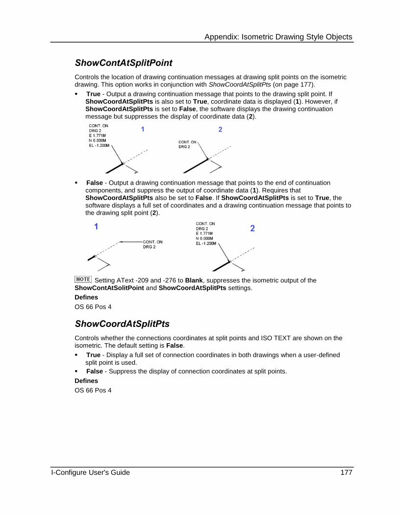
Appendix: Isometric Drawing Style Objects
I-Configure User's Guide 177
ShowContAtSplitPoint
Controls the location of drawing continuation messages at drawing split points on the isometric drawing. This option works in conjunction with ShowCoordAtSplitPts (on page 177).
True - Output a drawing continuation message that points to the drawing split point. If ShowCoordAtSplitPts is also set to True, coordinate data is displayed (1). However, if ShowCoordAtSplitPts is set to False, the software displays the drawing continuation message but suppresses the display of coordinate data (2).
False - Output a drawing continuation message that points to the end of continuation components, and suppress the output of coordinate data (1). Requires that ShowCoordAtSplitPts also be set to False. If ShowCoordAtSplitPts is set to True, the software displays a full set of coordinates and a drawing continuation message that points to the drawing split point (2).
Setting AText -209 and -276 to Blank, suppresses the isometric output of the ShowContAtSolitPoint and ShowCoordAtSplitPts settings.
Defines
OS 66 Pos 4
ShowCoordAtSplitPts
Controls whether the connections coordinates at split points and ISO TEXT are shown on the isometric. The default setting is False.
True - Display a full set of connection coordinates in both drawings when a user-defined split point is used.
False - Suppress the display of connection coordinates at split points.
Defines
OS 66 Pos 4

Appendix: Isometric Drawing Style Objects
178 I-Configure User's Guide
ShowCptFlowArrows
Controls the use of flow arrows that are plotted alongside certain types of in-line components. Their purpose is to show the fluid or gas flow direction in a pipeline. The default setting is True.
True - Display flow arrows.
False - Suppress the display of flow arrows.
Defines
OS 17 Pos 1
ShowDrainPosition
Controls whether the coordinate information at drain positions and ISO TEXT are shown on the isometric. The default setting is True.
True - Display the coordinate information.
False - Suppress the display of the coordinate information.
The AText number for the ISO TEXT used for drain position is -239; the default text is DRAIN.
Defines
OS 5 Pos 6
ShowEquipConn
Controls whether the coordinate information at connection to equipment nozzles and ISO TEXT are shown on the isometric drawing. The default setting is True.
True - Display the coordinate information.
False - Suppress the display of the coordinate information.
The AText number for the ISO TEXT used for connections to equipment nozzles is -208; the default is CONN. TO.
Defines
OS 5 Pos 2
ShowFlangeRotation
Controls the output of flange rotation angles, which are used by the fabricator when welding on flanges that have to be rotated away from the normal off-centre axes. Although the facility can be used on all types of isometrics, it is particularly beneficial on spool isometrics.
There are a variety of enclosure box styles that can be used for the output of flange rotation angles on the isometric controlled by FlangeRotationStyle property.For more information, see FlangeRotationStyle (on page 254).
True - Display flange rotation angles.
False - Suppress the display of flange rotation angles.
Defines
OS 124 Pos 1

Appendix: Isometric Drawing Style Objects
I-Configure User's Guide 179
ShowFlowArrows
Controls the use of flow arrows that are plotted directly on the pipe. Their purpose is to show the flow direction of fluid or gas in the pipeline. The size of the flow arrow is controlled by FlowArrowScale.
True - Show flow arrows on pipe on isometric.
False - Suppress flow arrows on pipe on isometric.
You can generate this type of flow arrow only if the relevant information is included in the input pipeline data file.
You can also use a separate type of flow arrow that is plotted alongside in-line fittings, either as well as, or instead of, the one output on pipe. For more information, see ShowCptFlowArrows (on page 178).
Defines
OS 112 Pos 1,2
FlowArrowScale (on page 254)
ShowGaskets
Controls the output of gaskets on the isometric drawing.
ISOGEN does not normally output a fitting shape to depict a gasket on the isometric drawing. Where a gasket is present between two flanged components, a gap appears between the components.
True - Output a gasket fitting shape on the isometric drawing.

Appendix: Isometric Drawing Style Objects
180 I-Configure User's Guide
False - Suppress output of a gasket fitting shape on the isometric drawing.
Defines
OS 17 Pos 2
ShowIsometricSpindles
Controls the display of valve and instrument spindles in isometric projection.
True - Display valve and instrument spindles in isometric projection.
False - Display valve and instrument spindles as flat.
Defines
OS 95 Pos 6

Appendix: Isometric Drawing Style Objects
I-Configure User's Guide 181
ShowMiscPosition
Controls whether the coordinate information at miscellaneous positions and ISO TEXT is shown on the isometric drawing. The default setting is True.
True - Display the coordinate information..
False - Suppress the display of the coordinate information.
The AText number for the ISO TEXT used for miscellaneous positions is -242; the default is Blank.
Defines
OS 5 Pos 7
ShowNozzles
Controls whether equipment nozzle indicators are plotted (in dotted line style) on the isometric drawing. The default setting is False.
True - Display equipment nozzle indicators.
False - Suppress the display of equipment nozzle indicators.
Defines
OS 111 Pos 1
ShowNSUnitsOnDrg
Controls how nominal size information is output in a number of tables and lists appearing on the isometric drawing. ISOGEN does not have an option when outputting the nominal size on whether the units (typically the “ character) is appended to the output text. To give you control over the output of the nominal size units, the software adds keywords to the appropriate control files.
True - Appends the keyword OUTPUT-UNITS to N.S, N.S.SEC and N.S.THIRD when this appears in the control files for tables and lists appearing on the isometric drawing. An example is shown below.
PRINTED-M/C-DATA-ITEMS
'PIPELINE-REFERENCE' 1 L
'REVISION' 18 L
'ITEM-CODE' 24 L
'N.S.' 41 L OUTPUT-UNITS
'QTY' 57 N
'GROUP' 64 L
False - Appends the keyword SUPPRESS-UNITS to N.S, N.S.SEC and N.S.THIRD when this appears in the control files for tables and lists appearing on the isometric drawing.
You can control nominal size units for the following output tables and report files:
Material List – Style 2
Material List – Style 3
Material List – Style 4
Material Control File
Cut Pipe List
Cut Pipe Report File
Weld List

Appendix: Isometric Drawing Style Objects
182 I-Configure User's Guide
Welding Report File
Site Welding Report File
Operations List (default – units output)
Site Assembly Report File (default – units output)
ShowNSUnitsInReports
Controls how nominal size information is output in a number of summary report files. ISOGEN does not have an option when outputting the nominal size on whether the units (typically the “ character) is appended to the output text. To give you control over the output of the nominal size units, the software adds keywords to the appropriate control files.
True - Append the keyword OUTPUT-UNITS to N.S, N.S.SEC and N.S.THIRD when this appears in the control files for summary report files. An example is shown below.
PRINTED-M/C-DATA-ITEMS
'PIPELINE-REFERENCE' 1 L
'REVISION' 18 L
'ITEM-CODE' 24 L
'N.S.' 41 L OUTPUT-UNITS
'QTY' 57 N
'GROUP' 64 L
'WEIGHT' 77 N
False - Append the keyword SUPPRESS-UNITS to N.S, N.S.SEC and N.S.THIRD when this appears in the control files for Operations List and Site Assembly Report File (these reports have units output by default).
You can control nominal size units for the following output tables and report files:
Material List – Style 2
Material List – Style 3
Material List – Style 4
Material Control File
Cut Pipe List
Cut Pipe Report File
Weld List
Welding Report File
Site Welding Report File
Operations List (default – units output)
Site Assembly Report File (default – units output)
ShowOpenEnd
Controls whether the coordinate information at the open end of pipe work and ISO TEXT are shown on the isometric drawing. The default setting is True.
True - Display the coordinate information.
False - Suppress the display of the coordinate information.
The AText number for the ISO TEXT used for open end is - 240; the default is Blank.
Defines
OS 5 Pos 3

Appendix: Isometric Drawing Style Objects
I-Configure User's Guide 183
ShowPipeLineCont
Controls whether the coordinate information for pipeline continuations and ISO TEXT are shown on the isometric drawing. The default setting is True.
True - Display the coordinate information.
False - Suppress the display of the coordinate information.
The AText number for the ISO TEXT used for pipeline continuation is -209; the default is CONT. ON.
Defines
OS 5 Pos 1
ShowReferenceDims
Controls whether reference dimensions are output on the isometric drawing.
True - Output reference dimensions.
False - Suppress the output of reference dimensions.
Defines
OS 119 Pos 3
ShowRPads
Controls the automatic generation of an item code and a material description on the material list and a plotted shape for the pad on the isometric drawing. The default setting is False.
True - Generate an item code and a material description and plotted pad shape to be shown on the isometric drawing.
False - Suppress the generation of an item code and a material description and plotted pad shape.
Defines
OS 77 Pos 3
ShowSiteAssemblyTable
Controls the display of the site assembly table on the isometric drawing. The default setting is False.
True - Display the site assembly table.
False - Suppress the display of the site assembly table.
Defines
OS 79 Pos 4

Appendix: Isometric Drawing Style Objects
184 I-Configure User's Guide
ShowSupports
Controls the display of pipe supports on the isometric drawing.
True - Display pipe supports on the isometric drawing and in the material list.
False - Suppress the display of pipe supports on the isometric drawing and the material list.
Defines
OS 40 Pos 1

Appendix: Isometric Drawing Style Objects
I-Configure User's Guide 185
ShowTapBrnchCoords
Controls the output of coordinates at tapped branch connection points--the point on the host component where the tapped branch is connected.
True - Output the coordinates.
False - Suppress the output of the coordinates.
Defines
OS 122 Pos 1
ShowVentPosition
Controls the display of coordinate information at vent positions and ISO TEXT on the isometric. The default setting is True.
True - Display the coordinate information.
False - Suppress the display of the coordinate information.
The AText number for the ISO TEXT used for connections to vent positions is -230; the default text is VENT.
Defines
OS 5 Pos 5
Drawing.Controls Object Sets options for system controls.
AppendStandardExts (on page 186)
AutoDrawingSplit (on page 186)
DateFormat (on page 187)
DateSource (on page 187)
DiagnosticLevel (on page 188)
DisconnectionMessage (on page 188)
DrawingRotationAngle (on page 188)
DrawingSize (on page 189)
FlatSpoolOrientation (on page 190)
FourDigitYear (on page 190)
HeatTracingOptions (on page 191)
IgnoreUserSplitPoints (on page 191)
IsometricType (on page 191)
IsoScale (on page 191)
MinAngleOffset (on page 192)
NoOfDrawings (on page 192)
NorthDirection (on page 193)
DrawingsPerFile (on page 193)
OutputFormat (on page 193)
OverwritePlotFile (on page 194)
PipeLineScale (on page 194)
PipeLineSplitting (on page 194)
PipeLineSplittingInTube (on page 195)

Appendix: Isometric Drawing Style Objects
186 I-Configure User's Guide
PipeNameInContMessages (on page 195)
PipeNameStyle (on page 195)
PlotFileLength (on page 196)
PlotFilePath (on page 196)
PostScriptSize (on page 196)
PrintedOutputPageLen (on page 197)
SetPipeLineDisconnected (on page 197)
ShowIsogenVer (on page 197)
StartDrawingNumber (on page 197)
SupportAdditionsWeight (on page 198)
TrueScale (on page 198)
Units (on page 198)
UseI01TypeExts (on page 199)
WeightOutput (on page 199)
LinearWeightDenominator (on page 192)
ContinuationGraphicsOnSpoolIsos (on page 187)
AppendStandardExts
True - Append plot file output format extension to the I01 type file name extension on all plot files generated that do not use a user-defined plot file prefix. The UseI01TypeExts property must also be set to True.
False - Suppress appending plot file output format extension to the I01 type file name extension on all plot files generated that do not use a user-defined plot file prefix.
Defines
OS 71 Pos 7
See Also UseI01TypeExts (on page 199)
AutoDrawingSplit
Invokes automatic splitting of drawings.
Unless IgnoreUserSplitPoints is set to True, this property is ignored if you manually-added pipeline split points are present in the pipeline data file.
True - Calculate the volume of pipeline graphics that can be satisfactorily displayed on the selected drawing size, and generate the required number of isometrics to contain the complete pipeline.
False - Use NoOfDrawings to specify a fixed number of drawings. Setting to False allows you to directly dictate how many isometric drawings are to be produced for a pipeline.
Only set the number of drawings in special cases, such as for single pipeline runs, since the setting is applied to all the pipelines in a run.
Defines
OS 7 Pos 1, 2
See Also IgnoreUserSplitPoints (on page 191) NoOfDrawings (on page 192)

Appendix: Isometric Drawing Style Objects
I-Configure User's Guide 187
ContinuationGraphicsOnSpoolIsos
Controls the display of continuation graphics at the ends of spool isometric drawings. Where a spool continues on another spool, an appropriate continuation message is also output on the isometric drawing.
False - Display continuation graphics on spool isometric drawings.
True - Suppress display of continuation graphics on spool isometric drawings.
Defines
OS 38 Pos 5
DateFormat
Controls the format of the date that is to be output on the isometric and in summary files.
None - Display no date.
British - Display the date in British format (dd/mm/yy)
European - Display the date in European format (dd/mm/yy).
American - Display the date in American format (mm/dd/yy).
Defines
OS 6 Pos 1
See Also DateSource (on page 187) FourDigitYear (on page 190)
DateSource
Takes the actual date that is output from either the pipeline data file that has been created by the host 3D design system or the computer system date at run time.
DataFile - Use the date contained in the pipeline data file.
System - Use the system clock date.
Defines
OS 6 Pos 2
See Also DateFormat (on page 187) FourDigitYear (on page 190)

Appendix: Isometric Drawing Style Objects
188 I-Configure User's Guide
DiagnosticLevel
Controls the amount of information written to the message file.
Low - Write ISOGEN program version and plot file generation messages to the message file.
Medium - Write plot and module run messages to the message file.
High - Write plot, module run, and ISOPLOT messages to the message file.
Defines
OS 55 Pos 1
DisconnectionMessage
Specifies an IDFGEN-generated diagnostic and controls output of disconnection messages on the isometric drawing.
True - Output disconnection message local to pipeline break where increased tolerance is used to connect pipeline.
False - Suppress output of local disconnection message where increased tolerance is used to connect pipeline.
Defines
OS 55 Pos 2
DrawingRotationAngle
Controls the rotation of the isometric drawing in a clockwise direction by a specified number of degrees. Where pipelines are oriented in a non-primary, or skewed, direction, the subsequent isometric drawing output can be congested and difficult to read. The ability to orient pipelines in the horizontal plane so that the majority of skewed pipeline sections are rotated to a primary direction can simplify isometric drawing output.
The example drawing below shows pipe oriented in a southeasterly direction:

Appendix: Isometric Drawing Style Objects
I-Configure User's Guide 189
The next example shows the same pipe rotated 45º so that it is now in a southerly direction:
0 - Orient isometric drawings in the horizontal plane using the setting defined by NorthDirection. This is the default setting.
Value - Orient isometric drawings in the horizontal plane in a clockwise direction by the specified number of degrees. Enter a value in tenths of a degree up to a maximum of 3600.
If you define a value, it overwrites the setting defined by NorthDirection (on page 193).
Defines
OS 42, Pos 4-7
DrawingSize
Specifies a standard paper size for the isometric drawing.
European Sizes
A0 - 841 x 1189 mm
A1 - 594 x 841 mm
A2 - 420 x 594 mm
A3 - 297 x 420 mm
A4 - 210 x 297 mm
ANSI Sizes
A - 8.5" x 11"
B - 11" x 17"
C - 17" x 22"
D - 22" x 34"
E - 34" x 44"
If set to Custom, then you must also set CustomHeight and CustomWidth.
Defines
OS 14 Pos 1, 2
See Also CustomHeight (on page 329) CustomWidth (on page 329)

Appendix: Isometric Drawing Style Objects
190 I-Configure User's Guide
FlatSpoolOrientation
Controls placement of the longest pipe in a flat spool drawing. Acceptable options are::
Maximum Legs Flat
Parallel Legs Flat
Longest Leg in E/W plant, Second Longest in N/S plane
Setting FlatSpoolOrientation to Parallel Legs Flat is not recommended.
Defines
OS 42 Pos 3
See Also FlatSpoolUpArrow (on page 190)
FlatSpoolUpArrow
Allows the Up direction to be displayed on the isometric drawing. The Up direction shown is relevant to the longest leg length output in the horizontal plane (bottom left to top right) of the isometric drawing.
True - Display Up direction on longest leg of flat spool. This setting is only applicable when FlatSpoolOrientation is set to Longest Leg in E/W plant, Second Longest in N/S plane.
False - Display North arrow on all drawings except flat spool isometric drawings.
The following example shows the Up direction rotated 90-degrees counter clockwise:
Defines
OS 42 Position 2
See Also FlatSpoolOrientation (on page 190)
FourDigitYear
Controls whether the year portion of the date is output as two or four digits.
True - Output four-digit year, such as 2009.
False - Output two-digit year, such as 09.
Defines
OS 6 Pos 3
See Also DateFormat (on page 187) DateSource (on page 187)

Appendix: Isometric Drawing Style Objects
I-Configure User's Guide 191
HeatTracingOptions
Controls heat tracing options.
On - Use heat tracing options.
Off - Suppress the use of heat tracing options.
Defines
OS 21 Pos 4
IgnoreUserSplitPoints
True - Ignore user-defined drawing split points present in the piping data file.
False - Process user-defined drawing split points present in the piping data file.
Defines
OS 7 Pos 3
IsometricType
Sets the required isometric type.
Combined - Fabrication, erection and offshore information.
Erection/Offshore - Erection/offshore type isometric drawing.
Fabrication Only - Fabrication only isometric.
Flat Spool (Flat) - Individual flat spool isometrics (maximum legs flat).
Flat Spool (Parallel) - Individual flat spool isometrics (maximum legs parallel).
Spool - Individual spool isometrics As-Built orientation.
Material List Only - Isometrics suppression - no isometric drawings are generated.
Combined Material - Combined material list only, without pipeline graphics.
Erection Material - Erection material list only, without pipeline graphics.
Fabrication Material - Fabrication material list only, without pipeline graphics.
Spool Material - Spool material list only, without spool graphics.
Defines
OS 21 Pos 1 & 2
IsoScale
Controls the finished isometric drawing size. You can increase or decrease the final plotted isometric size from the size defined by DrawingSize, or CustomHeight and CustomWidth.
0 or 100 - No scaling change (100% of set size). The software generates the isometric drawing at the size defined by DrawingSize or CustomHeight and CustomWidth.
n - Scale the drawing to increase or decrease the final isometric size by n%, where n is an integer number. For example, n = 71 generates a reduced size drawing at 71% of the set size, such as A2 reduced to A3. Whereas n = 120 generates an increased size drawing at 120% of the set size.
Defines
OS 32
See Also DrawingSize (on page 189)

Appendix: Isometric Drawing Style Objects
192 I-Configure User's Guide
LinearWeightDenominator
Specifies the units for the linear weight denominator, regardless of the units used for weights.
None - The linear denominator is the default. For example: LBS/FT when weight is in LBS, and KGS/M when weight is in KGS.
m - The linear denominator is in metres. For example: LBS/M when weight is in LBS, and KGS/M when weight is in KGS.
ft - The linear denominator is in feet. For example: LBS/FT when weight is in LBS, and KGS/FT when weight is in KGS.
The weight unit is specified in the WeightOutput property.
Defines
OS 41 Pos 4
WeightOutput (on page 199)
MinAngleOffset
Controls how the software interprets and acts on small angular deviations detected in the pipeline input data. These deviations can lead to small unwanted skews being generated on the isometric. You can define an angular cut-off value with this property so that any skew that is found to have an angular deviation below this value is ignored by the software and not treated as a skew. The default setting is 0.
0 - Use no angular offset tolerance.
Value - Use the user-defined required angle tolerance. Type a value in range 1-10, such as 0.5 for 0.5-degrees.
Defines
OS 115
NoOfDrawings
Specifies the number of drawing sheets required for split control.
0 - Automatic control of drawing numbers.
Value - User-defined number of drawings. Type a value in range 1-99
Unless IgnoreUserSplitPoints is set to True, this property setting is ignored if manually placed pipeline split points are present in the pipeline data file.
This option dictates how many drawing sheets are extracted for a pipeline. Therefore, you should use this option only for special cases for single pipe runs as the setting applies to all the pipelines in a run.
To use the NoOfDrawings option, you must set the AutoDrawingSplit option to False.
Defines
OS 7 Pos 1 & 2
See Also IgnoreUserSplitPoints (on page 191)

Appendix: Isometric Drawing Style Objects
I-Configure User's Guide 193
NorthDirection
Controls the viewing direction (isometric orientation), or the direction that the north arrow points on the isometric drawing. There are four orientation options you can choose:
Top Left
Top Right
Bottom Left
Bottom Right
The option you select is indicated on the isometric by the direction the north arrow is pointing. You can specify that the arrow be displayed in a box with NorthArrowBox (on page 261).
Defines
OS 42 Pos1
DrawingsPerFile
Controls how and where any isometric drawings are to be output.
All On Same Sheet - Output isometric drawings generated during a run to a single plot file or to a series of plot files, depending upon the PlotFileLenth setting
One Per File - Generate an individual plot file for each isometric drawing.
One Per Sheet - Plot each ISOGEN drawing sheet to a separate sheet within a single drawing file.
Only applies to SmartSketch (IGR) and SmartPlant Shape2D (SHA) formats.
Defines
OS 31 Pos 1
See Also PlotFileLength (on page 196)
OutputFormat
Controls the 2D CAD file format that ISOGEN creates. Use the OutputFormat list to select the required output format.
AutoCAD DXF (DXF)
MicroStation (DGN)
Smart DWG (DWG)
Smart DGN (DGN)
Smart DGN v8 (DGN)
SmartSketch (IGR)
Shape2d (SHA)
POD2
POD3
ISOGEN
Postscript
In the case of Smart DGN v8 output, template backing sheets (supplied by Alias) are suffixed with .dg8.
To use .dg8 templates:

Appendix: Isometric Drawing Style Objects
194 I-Configure User's Guide
f. Rename the .dgn v5 template backing sheets to .dg5.
g. Rename the .dg8 templates to .dgn.
Defines
OS 71 Pos 1
OverwritePlotFile
Overwrites and deletes any plot files existing with the same name.
True - Allocate plot file name using selected sequence method after deleting previously generated files.
False - Allocate next available plot file, generate name using selected sequence method.
Defines
OS 31 Pos 2
PipeLineScale
Increases or decreases the scale of the pipeline picture part of the isometric only, while leaving all other parts, such as the drawing frame, material list, title block and line summary areas, unaltered. Using this property, you can re-scale the pipeline picture and all text pointing to it.
0 or 100 - Use the default scale.
Value - Use the user-defined integer number to increase or decrease the scaling effect as a percentage.
Defines
OS 34
PipeLineSplitting
Controls the amount of drawing data that triggers a drawing split. This value is a scale factor expressed as a percentage. Setting a value less than 100 causes less of the pipeline to appear on each drawing before automatic splitting occurs, resulting in a less crowded drawing.
This option is intended only for modest modifications of the drawing whitespace. Specify a value in the range 90-110. If a particular value does not work, gradually adjust the value and re-extract the drawing to check the results.
0 or 100 - Default for what ISOGEN considers to be the limit for drawing information content. This limit is set within the software and varies for each size of drawing.
Value - Increase or decrease the drawing information content as a percentage.
Defines
OS 38

Appendix: Isometric Drawing Style Objects
I-Configure User's Guide 195
PipeLineSplittingInTube
Controls the actions taken by the software whenever the ISOGEN automatic pipeline split facility selects a split point that is located in a straight length of pipe.
Normal - Default for pipeline splitting to function as normal when the split point occurs along a section of pipe. The relevant split point information is passed back to the 3D design system using the isometric repeatability file, if it is being used.
Reject - If a pipeline split occurs along a section of pipe, the warning message, UNACCEPTABLE SPLIT POINT, is written to the message file. No plots are produced and no information is written to the isometric repeatability file for the pipeline.
Message - If a pipeline split occurs along a section of pipe, the warning message, UNACCEPTABLE SPLIT POINT, is written to the message file. Plots are produced with the message, UNACCEPTABLE SPLIT POINT plotted at the top of each affected drawing. No information is written to the isometric repeatability file for the pipeline.
Defines
OS 108
PipeNameInContMessages
Controls whether the pipeline name is output as part of the drawing continuation message on the isometric.
True - Output pipeline name as part of the drawing continuation message.
False - Output a standard drawing message.
Defines
OS 38 Pos 4
PipeNameStyle
Controls the style of pipeline name output for drawing continuation messages.
If PipeNameInContMessages is True.
Blank - Output a standard drawing continuation message.
Drawing Identifier - Output a drawing continuation message that includes CLIENT-DRAWING-IDENTIFIER.
Pipe Reference - Output a drawing continuation message includes pipeline name.
Sequence Number - Output a drawing continuation message that includes PIPELINE-DRAWING-SEQUENCE-NUMBER.
Spool Drawing Sequence Number - Output a drawing continuation message that includes SPOOL-DRAWING-SEQUENCE-NUMBER.
Defines
OS 38 Pos 4
See Also PipeNameInContMessages (on page 195)

Appendix: Isometric Drawing Style Objects
196 I-Configure User's Guide
PlotFileLength
Controls the physical length of the plot file that is generated by ISOGEN.
It is only necessary to set this property when OneFilePerDrawing is set to False, and the required PlotfileLength is different than the built-in default value of 3275mm.
0 - Default for plot file length of 3275mm.
Value - The required plot file length in whole mm's.
The maximum length is limited to 3350mm.
Defines
OS 1
See Also DrawingsPerFile (on page 193)
PlotFilePath
Specifies the folder into which drawings are written. Double-click in the PlotFilePath box and use the Browse for file dialog box to navigate to the required folder.
PostScriptSize
Specifies the PostScript plotter size.
European Sizes:
A0 - 841 x 1189 mm
A1 - 594 x 841 mm
A2 - 420 x 594 mm
A3 - 297 x 420 mm
A4 - 210 x 297mm
ANSI Sizes
A - 8.5" x 11"
B - 11" x 17"
C - 17" x 22"
D - 22" x 34"
E - 34" x 44"
Defines
OS 14 Pos 3 & 4

Appendix: Isometric Drawing Style Objects
I-Configure User's Guide 197
PrintedOutputPageLen
Controls the number of lines per page on any printed output (reports) generated by the ISOGEN system.
0 - Use the default for 55 lines per page.
Value - Specify the required number of lines to be output per page. Type the required value (integer number).
Defines
OS 63
SetPipeLineDisconnected
Specifies an IDFGEN-generated diagnostic.
True - Set pipeline to disconnected when an increased tolerance is used to connect pipeline. Output a disconnected pipeline message at top of drawing.
False - Suppress output of disconnected pipeline message at top of drawing if pipeline has connected using the increased tolerance.
Message is always output if pipeline does not connect using increased tolerance.
Defines
OS 55 Pos 3
ShowIsogenVer
Controls the optional plotting of the ISOGEN version banner, together with the run date and generation time of the isometric. The information is plotted on a single line located at the bottom left-hand corner of the isometric, but inside any cut marks that can be present.
True - Plot the banner.
False - Suppress plotting of the banner.
Defines
OS 127
StartDrawingNumber
Allows the first sheet to start at an alternative number instead of starting with drawing number 1
0 - Start first sheet at drawing number 1.
x - Start first sheet at x+1.
Defines
OS 31, Pos 3-5

Appendix: Isometric Drawing Style Objects
198 I-Configure User's Guide
SupportAdditionsWeight
Controls inclusion of the weight of additional material associated with supports when performing centre-of-gravity calculations. The default setting is Include.
Include - Include the weight of additional materials.
Ignore - Ignore the weight of additional materials.
Defines
OS 40 Pos 6
TrueScale
Attempts to adjust the length of sections of pipe to be proportional to their actual physical length.
True - Use true scaling of isometrics (proportional pipe lengths).
False - Use normal scaling of isometrics (variable pipe lengths).
Defines
OS 95 Pos 3
Units
Defines the style of units used throughout: Metric or Imperial.
Metric / MM Bores - Use millimetre lengths and millimetre pipe bores.
Metric / Inch Bores - Use millimetre lengths and inch pipe bores.
Imperial / Inch Bores - Use inch lengths and inch pipe bores.
You can specify the changeover point from where lengths are reported in inches only, to feet and inches.

Appendix: Isometric Drawing Style Objects
I-Configure User's Guide 199
Imperial / MM Bores - Use inch pipe bores with lengths in feet and inches.
The combination MM bore, FT-IN dimensions is invalid
Defines
OS 41 Pos 1
See Also FtInTolerance (on page 214)
UseI01TypeExts
Controls the use of I01 type extensions.
True - Use I01 type filename extensions on all plot files generated that do not use a user defined plot file prefix.
False - Use normal filenames / extensions.
Defines
OS 71 Pos 7
WeightOutput
Controls how component weights are displayed on the isometric drawing. The default setting is None.
None - Output no weight information. Applies to all outputs, including such things as material lists, weight output on drawing frame, and material control files.
Kg - Input and output all weights in kilograms (Kgs).
Lb - Input and output all weights in pounds (Lbs.)
LinearWeightDenominator specifies the units used for the linear weight denominator, irrespective of the units used for weights.
Defines
OS 41 Pos 4
See Also LinearWeightDenominator (on page 192)

Appendix: Isometric Drawing Style Objects
200 I-Configure User's Guide
Drawing.Definitions Object Contains a collection of options called Definitions, which is used to define how to represent pipeline components or facilities on the drawing. For more information, see Drawing.Definitions Definitions Collection (on page 201).
LineStyleTable (on page 200)
Count (on page 201)
LineStyleTable
Displays the LineStyle Table window, which is a free format text field that you can use to define a standard name to line style number mapping. Any line style number that you enter here is displayed in the LineStyle list.
19. Double-click the LineStyleTable Value box.
The software displays the LineStyle Table window.
20. Type a line style number and its corresponding line style name.
21. Continue entering line style numbers and names as needed, pressing Enter after each entry.
22. When you are finished, click File > Update to save the line styles.
The entry must be the name of a line style defined in the output CAD system.
The software supports up to 1000 user-defined line styles.
See Also LineStyle (on page 203)

Appendix: Isometric Drawing Style Objects
I-Configure User's Guide 201
Count
Displays the number of definitions stored in the Drawing Definitions collection.
Drawing.Definitions Definitions Collection
Defines how to represent pipeline components or facilities on the drawing. For example, you can specify that valves are to be drawn 1.5 times normal size with a line thickness of 1 on layer 5, and appear in the colour blue. This collection is used to construct the corresponding Drawing Definition (DDF) file.
The value that appears in parentheses after the collection name is a count of how many definitions are stored in the collection.
AppliesTo (on page 201)
LowerBore (on page 201)
UpperBore (on page 202)
Category (on page 202)
Colour (on page 202)
Layer (on page 203)
DScale (on page 203)
ThicknessActual (on page 203)
ThicknessLogical (on page 203)
LineStyle (on page 203)
See Also Add an Item to a Collection (on page 171) Remove an Item from a Collection (on page 172)
AppliesTo
Specifies the component type. This is set using a list, which includes the allowable settings for this property.
LowerBore
Defines the minimum bore as an integer or real number. This value must be in the current nominal size units.
When there are two or more definitions with the same AppliesTo setting, you can use a zero (0) in the first of the lower bore positions to signal there is no lower bore, as shown in the example below.
AppliesTo LowerBore UpperBore
Pipeline 0 2
Pipeline 2.5 6
Pipeline 8 0
I-Configure displays the LowerBore/UpperBore parameter together, rather than separated as they are currently.
See Also AppliesTo (on page 201)

Appendix: Isometric Drawing Style Objects
202 I-Configure User's Guide
UpperBore
Defines the maximum bore as an integer or real number. This value must be in the current nominal size units.
When there are two or more definitions with the same AppliesTo setting, you can use a zero (0) in the last maximum bore position to signal there is no maximum bore limit, as shown in the example below.
AppliesTo LowerBore UpperBore
Pipeline 0 2
Pipeline 2.5 6
Pipeline 8 0
I-Configure displays the LowerBore/UpperBore parameter together, rather than separated as they are currently.
Category
Specifies the category for the definition. For example, you can choose Fabrication, Erection, Offshore, and so forth.
Colour
Specifies the index number that represents a specific colour as defined in the output drawing software.
AutoCAD uses a fixed 256 colour pallet starting at 1 (red) to 256. In MicroStation, in addition to a default colour pallet, each design file can have a unique custom colour table. For example, colour index number 3 may be red in one design file, but it may be green in another.
The table below shows a colour comparison between a sampling of AutoCAD and MicroStation colour index numbers.
AutoCAD Colour Index Number
MicroStation Colour Index Number
Colour Output on Isometric Drawing
1 3
2 4
3 2
4 7
5 1
6 5
7 0
8 9
9 14
For specific information about AutoCAD, MicroStation, and other 3rd party drawing software colour tables, refer to the product documentation delivered with your software.

Appendix: Isometric Drawing Style Objects
I-Configure User's Guide 203
Layer
Defines a number that corresponds to the layer. This number is an integer that identifies the required layer (level) to which the component type is to be assigned. You must use a value in the range 1-50.
DScale
Specifies an integer value for the scale that represents an increase or decrease to the basic 100% standard symbol size for all types of fitting. This value must be in the range 75 - 200.
ThicknessActual
Defines the actual thickness (width) of the plotted line in millimetres (a real number). This value is in the range 0.0 to 10.0.
ThicknessLogical
Specifies an integer for the required thickness. This value is in the range 0 - 99.
LineStyle
Specifies the number that corresponds to the line style that is to be output on the isometric drawing. A line style is a simple pattern of lines and gaps. In the LineStyle list, the 12 line styles generated by ISOGEN, shown below, are listed by default.
1000
1001
1002
1003
1004
1005
1006
1007
1008
1009
1010
1011
You can define additional line styles using LineStyleTable.
The ISOGEN-generated line styles only apply for showing heat tracing on the isometric drawing. They do not apply for piping. User-defined line styles can be applied for showing either heat tracing or piping.
See Also LineStyleTable (on page 200)

Appendix: Isometric Drawing Style Objects
204 I-Configure User's Guide
Drawing.Dimensions Object Sets options for dimension display on the isometric drawing.
AdditionalAllowanceFormat (on page 205)
AddRoundOff (on page 205)
BranchBoreLimit (on page 206)
BranchCptLimit (on page 206)
CoordOutputBends (on page 207)
CoordOutputBranches (on page 207)
CoordOutputHTCpts (on page 207)
CoordSupports (on page 208)
CoordType (on page 208)
CurvedPipeDimensioning (on page 208)
DoubleUnits (on page 208)
FabWeldsInPipe (on page 209)
Format (on page 210)
FtInTolerance (on page 214)
Gaskets (on page 215)
GasketDimPrecision (on page 216)
ImperialFormat (on page 217)
IdfgenConnectionTolerance (on page 218)
Inches (on page 218)
IsometricText (on page 218)
JacketDimensioning (on page 219)
MetresCoordinates (on page 219)
MetresDimensions (on page 219)
MinOffset (on page 219)
NominalSize (on page 220)
NonLinearValves (on page 221)
Overall (on page 221)
OverallAcrossFabItemsOnly (on page 222)
PipesThroughPenetrationPlates (on page 222)
SeparatePulledBend (on page 223)
StandOutComposite (on page 223)
StandOutOverall (on page 224)
StandOutVertical (on page 225)
SuppDimAsDim (on page 225)
SuppDimToCentre (on page 226)
SuppFormat (on page 227)
SuppOptions (on page 228)
SuppStandOut (on page 229)
TapOnCpt (on page 230)
TapOnPipe (on page 230)
TapBranchDimension (on page 231)
TapOnPipeFittings (on page 233)

Appendix: Isometric Drawing Style Objects
I-Configure User's Guide 205
USAStyle (on page 233)
ValveBW (on page 234)
ValveCP (on page 234)
ValveFL (on page 235)
ValveHY (on page 236)
ValveLimit (on page 237)
ValvePL (on page 238)
ValveSC (on page 238)
ValveSW (on page 239)
VertOption (on page 240)
WeldDimensionAccuracy (on page 241)
WeldDimensioning (on page 241)
AdditionalAllowanceFormat
Controls how additional allowances are displayed alongside or as part of dimensions.
Suppress - Display no additional allowances.
Dim + Allowance -Display dimension plus allowance.
Dim Includes Allowance - Add allowance to dimension.
Only use Dim Includes Allowance if you are using a Spool style.
Defines
OS 9 Pos 5
AddRoundOff
Controls the Dimension Round Off Carry-Over function, which is used to control how remainders are handled when dimensions are calculated and output on the isometric. At branch locations, or components, this permits the remainder part of a dimension either to be carried over and added to the next dimension, or discarded.
Normal - Round off dimensions to + or - 1mm, or 1/16th-inch, and carries over any reminder to the next dimension.
Branch Intersect - Round off dimensions to + or - 1mm or 1/16th-inch with no carry-over of the remainder beyond a branch intersection.
Current Component - Round off dimensions to + or - 1mm or 1/16th-inch with no carry-over of the remainder beyond current component.
Defines
OS 117

Appendix: Isometric Drawing Style Objects
206 I-Configure User's Guide
BranchBoreLimit
Specifies a branch bore limit to suppress dimensions. The acceptable range of values is 0-999. BranchBoreLimit works in conjunction with BranchCptLimit, if defined.
0 - Dimension all pipe.
Value (in range 0-999) - Suppress the dimensions of branches having a bore equal to or less than the defined value. Value is in 1/16th of an inch or mm, depending on the bore units. For example, the branch in the following illustration has a pipe bore of less than the value stated in BranchBoreLimit; consequently, it is not dimensioned.
Any branch containing pipe (100 record), fixed length pipe (101 record) or pipe block (103 record) does not have branch dimension suppression applied to it.
Branch dimension suppression using this property does not apply to tapped branches.
BranchBoreLimit and BranchCptLimit work either independently of each other or together, depending upon your requirements.
Defines
OS 81 Pos 4,5,6
See Also BranchCptLimit (on page 206)
BranchCptLimit
Controls the dimensioning of branches based on the number of components. Works in conjunction with BranchBoreLimit, if defined.
Branches with a specified number of components are un-dimensioned.
Blank - Dimension all branches.
Value (in range 0-99) - Suppress dimensions for branches having a number of components equal to or less than the specified value. Gasket and bolt entries are counted as components. For example, the branch in the following illustration has six components: a weldolet, a weld neck flange, two gaskets, a valve and a blind flange. In this example, BranchCptLimit has been set to 7, so the branch has not been dimensioned.
Any branch containing pipe (100 record), fixed length pipe (101 record) or pipe block (103 record) does not have branch dimension suppression applied to it.

Appendix: Isometric Drawing Style Objects
I-Configure User's Guide 207
Branch dimension suppression using this property does not apply to tapped branches.
The BranchBoreLimit and BranchCptLimit properties work either independently of each other or together, depending upon your requirements.
Defines
OS 81 Pos 7 & 8
See Also BranchBoreLimit (on page 206)
CoordOutputBends
Controls whether coordinates and elevations are printed at bends and elbows on the isometric drawing.
None - Output no elevation coordinates.
Elev at changes - Output elevations when changed.
Elev and coords at changes - Output elevations and coordinates that have changed.
Full - Output a full set of coordinates.
Defines
OS 66 Pos 2
CoordOutputBranches
Controls the coordinate display at branch intersections.
None - Output no elevation coordinates.
Elev at changes - Output elevations when changed.
Elev and coords at changes - Output elevations and co-ordinates that have changed.
Full - Output a full set of coordinates.
Defines
OS 66 Pos 3
CoordOutputHTCpts
Controls whether coordinates are output on heat traced components.
On - Output coordinates on heat traced components.
Off - Suppress coordinates on heat traced components.
Defines
OS 66 Pos 9

Appendix: Isometric Drawing Style Objects
208 I-Configure User's Guide
CoordSupports
Controls output of coordinates at different types of pipe supports.
None - Suppress display of coordinates on pipe supports.
Fabrication - Output coordinates at Fabrication pipe supports only.
Erection - Output coordinates at Erection pipe supports only.
Offshore - Output coordinates at Offshore pipe supports only.
All - Output coordinates at all pipe supports.
Defines
OS 66 Pos 6
CoordType
Controls the output type for supplementary coordinates, that is, coordinates at bends or at branches. You can choose output with arrows or witness lines. The default setting is Arrowed.
This option does not apply to end connection coordinates. It also does not apply when CoordOutputBends or CoordOutputBranches is set to Full.
Arrowed - Output coordinates and elevations as arrowed-out message type.
Witness Lines - Output coordinates and elevations along witness lines.
Defines
OS 66 Pos 1
CurvedPipeDimensioning
Controls the dimensioning of curved pipe.
Message - Output curved pipe dimensions as a message.
Standard - Output curved pipe dimensions as a standard dimension.
Suppress - Suppress curved pipe dimensions.
Defines
OS 84 Pos 1
DoubleUnits
Controls whether measurements are output in both imperial and metric units, or just one. The default setting is False.
True - Output measurements in both imperial and metric units.
False - Output measurements in one type of unit only.
Defines
OS 9 Pos 7
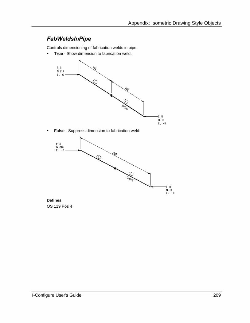
Appendix: Isometric Drawing Style Objects
I-Configure User's Guide 209
FabWeldsInPipe
Controls dimensioning of fabrication welds in pipe.
True - Show dimension to fabrication weld.
False - Suppress dimension to fabrication weld.
Defines
OS 119 Pos 4

Appendix: Isometric Drawing Style Objects
210 I-Configure User's Guide
Format
Controls the dimension format on the isometric drawing.
Basic - Plot ordinary string dimensions, support/message dimensions, and reference dimensions on the isometric drawing. This is the default setting.

Appendix: Isometric Drawing Style Objects
I-Configure User's Guide 211
Combined Erec/Offsh - Basic - Plot ordinary string dimensions. Do not dimension separately erection pipe fittings (bends, elbows, tees, and so forth), support/message dimensions and reference dimensions on the isometric drawing.

Appendix: Isometric Drawing Style Objects
212 I-Configure User's Guide
Composite - Plot composite dimensions together with support/message dimensions and reference dimensions on the isometric drawing.

Appendix: Isometric Drawing Style Objects
I-Configure User's Guide 213
Combined Erec/Offsh - Composite - Plot composite dimensions. Do not dimension separately erection pipe fittings (bends, elbows, tees, and so forth), support/message dimensions and reference dimensions on the isometric drawing.
Support - Plot only support/message and reference dimensions on the isometric drawing.

Appendix: Isometric Drawing Style Objects
214 I-Configure User's Guide
Reference Only- Plot only reference dimensions on the isometric drawing. Suppress all other dimensions.
Full String - Plot full string dimensions, support/message dimensions, and reference dimensions on the isometric drawing. All components are dimensioned individually.
Pipe Only - Plot pipe dimensions, support/message dimensions, and reference dimensions on the isometric drawing. Suppress fitting dimensions.
Defines
OS 9 Pos 1

Appendix: Isometric Drawing Style Objects
I-Configure User's Guide 215
FtInTolerance
Defines a value below which a ft-in dimension appears in inches. Type a value in whole inches. This value must be greater than 12.
In the example below, the 19.9/16" long pipe is dimensioned as 1' 7.9/16", as FtInTolerance is set at 19.
In the next example, the same pipe is dimensioned as 19.9/16", as FtInTolerance is set at 20.
Defines
OS 41 Pos 6 & 7
Gaskets
Specifies gasket dimensions. You can choose to not show gasket dimensions, to include the dimension with the component, or to treat the dimension separately.
None - Suppress gasket dimensions.
Gasket thicknesses are not included. The component dimension is indicated by the presence of two leader lines.

Appendix: Isometric Drawing Style Objects
216 I-Configure User's Guide
Included - Include gasket dimensions with the component.
Gasket thicknesses are included. The component dimension is indicated by the presence of only single leader lines.
The length of the valve has now increased by the thickness of the gaskets (2mm in this case) either side.
Separate - Dimension gaskets separately.
Defines
OS 9 Pos 2
See Also GasketDimPrecision (on page 216)

Appendix: Isometric Drawing Style Objects
I-Configure User's Guide 217
GasketDimPrecision
Controls precise dimensioning of gaskets.
True - Output gasket dimensions to the nearest 1/10th mm.
False - Output gasket dimensions to the nearest mm.
Defines
OS 119 Pos 5
See Also Gaskets (on page 215)
ImperialFormat
Controls the format of imperial measurements used on the isometric drawing.
Standard - Output standard ft/in format: 6' 10.3/4".
Standard dash - Add a dash between the feet and inches: 6'-10.3/4".
Space dash - Use a blank space instead of a dot (.) between inches and fractions of an inch: 6'-10 3/4".
Stacked fractions with dash - Output stacked fractions with a dash: 6'-10¾".
Stacked fractions without dash - Output stacked fractions without a dash: 6' 10¾".
1DecimalPlace - Output decimal inches to 1 decimal place.
2DecimalPlace - Output decimal inches to 2 decimal places.
3DecimalPlace - Output decimal inches to 3 decimal places.
4DecimalPlace - Output decimal inches to 4 decimal places.
The Stacked fractions options only apply to MicroStation DGN output.
Defines
OS 41 Pos 3

Appendix: Isometric Drawing Style Objects
218 I-Configure User's Guide
IdfgenConnectionTolerance
Controls the tolerance to be used when connecting components in IDFGEN. Set a value in mm.
Backward Compatibility
To avoid problems where this control is set as a single value, no tolerance is set in Option Switch 116, Positions 4-6. IDFGEN continues to use positions 1-3 to determine the connection tolerance.
Defines
116 Pos 4-6
See Also MinOffSet (on page 219)
Inches
Controls whether pipes are dimensioned in inches only or in feet and inches. The default setting is False.
True - Output dimensions in inches.
False - Output dimensions in feet/inches for any dimensions greater than 24-inches.
Inches overrides FtInTolerance.
Defines
OS 41 Pos 6
See Also FtInTolerance (on page 214)
IsometricText
Dimension text and messages placed along a section of pipe in isometric projection (oblique angle \ slanted text). Text oblique angle is adjusted to be parallel to the dimension standout direction. ISOGEN attempts to set a vertical dimension standout for horizontal sections of pipeline wherever practical.
True - Text is isometric.
False - Text is not isometric.
This feature is only available for DXF format output styles generated using the POD interface.
Defines
OS 8 Pos 3

Appendix: Isometric Drawing Style Objects
I-Configure User's Guide 219
JacketDimensioning
Controls how dimensioning is used for jacketed pipework.
Full - Full jacket dimensioning.
Minimal - Minimal detail.
Defines
OS 9 Pos 9
MetresCoordinates
Determines whether to plot coordinates in M.mm format
mm - Output coordinates in mm format.
m - Output coordinates in M.mm format.
10th mm - Output coordinates in 10th mm format. The following example shows dimensions to nearest 10th mm:
Defines
OS 41 Pos 2
See Also MetresDimensions (on page 219)
MetresDimensions
Determines whether to plot metric dimensions in M.mm format
mm - Output dimensions in mm format.
m - Output dimensions in M.mm format.
10th mm - Output dimensions in 10th mm format.
Defines
OS 41 Pos 2
See Also MetresCoordinates (on page 219)

Appendix: Isometric Drawing Style Objects
220 I-Configure User's Guide
MinOffset
Controls how small dimensional deviations detected in the input pipeline data file are to be interpreted and acted upon. These deviations can lead to small, unwanted skews being generated on the isometric drawing. You can use MinOffset to define a dimensional cut-off value, whereby any offset coordinate numerically below this value is ignored by the software.
0 - Use the default for no dimensional offset tolerance to be set.
Value - Use the user-defined value (real number). Set to the required dimensional tolerance in mm or inches, depending on the setting of the drawing units. For example, you can type 1.0 mm or 0.04 inch.
Defines
OS 116 Pos 1-3
See Also IdfgenConnectionTolerance (on page 218)
NominalSize
Controls whether nominal size is output at branch (tee/olet/cross) and reducer locations.
True - Output nominal size information at branches and reducers as normal.
False - Suppress output of nominal size information at branches and reducers.
Defines
OS 41 Pos 8

Appendix: Isometric Drawing Style Objects
I-Configure User's Guide 221
NonLinearValves
Produces arrowed dimensions for angle, 3-way, and 4-way valve and instrument legs. Otherwise, the software prints a message. The default setting is False.
True - Dimension angle, 3-way and 4-way valve and instruments normally.
False - Dimension angle, 3-way and 4-way valve and instruments using message.
Defines
OS 9 Pos 8
Overall
Controls the use of overall dimensions. You can specify whether overall dimensions are plotted, and if they are, which type.
None - Plot no overall dimensions.
Across Branches - Plot overall dimensions across branches (tees, olets and crosses).

Appendix: Isometric Drawing Style Objects
222 I-Configure User's Guide
Stop At Branches - Plot overall dimensions that stop at branches.
Valves / Across Branches - Plot overall dimensions to valve centres and across branches.
Valves / Stop At Branches - Plot overall dimensions to valve centres, stopping at branches.
Overall dimensions to valve centres are only available to valves that have a spindle.
Defines
OS 118 Pos 1
OverallAcrossFabItemsOnly
Controls the output of overall dimensions across spool breaks.
True - Output overall dimensions across fabrication items only.
False - Output overall dimensions across component categories.
Defines
OS 118 Pos 4

Appendix: Isometric Drawing Style Objects
I-Configure User's Guide 223
PipesThroughPenetrationPlates
Controls the dimensioning of pipes passing through penetration plates.
Dimension From Adjacent Plate Face - Dimension pipes passing through penetration plates from adjacent plate face.
Dimension From Same Plate Face - Dimension pipes passing through penetration plates dimensioned from same plate face.
Defines
119 Pos 6
SeparatePulledBend
Controls how bends are dimensioned. The default setting is False.
True - Plot separate dimensions for the pipe and bend sections of pulled bends.
False - Plot combined dimensions for the pipe and bend sections of pulled bends.
Defines
OS 9 Pos 6
StandOutComposite
Controls dimension line standout distances for the following:
23. String and composite dimensions that are normally plotted as the middle layer of multi-layer dimensions.
24. Dimensioned messages, support dimensions and reference dimensions on the inner layer, but only when SuppStandOut is not set.
25. Overall dimensions on the outer layer, but only when StandOutOverall is not set.
In the StandOutComposite box, type one of the following:
0 - If the value is set to 0 (zero), the default, then the following standard dimension line standouts are used:
When TextSize is set to
Small
String / Composite Dimension Standout = 12mm.
Messages / Support & Reference Dimension Standout - 6mm.
Overall Dimension Standout = 18mm.
Medium
String / Composite Dimension Standout = 14mm.
Messages / Support & Reference Dimension Standout = 7mm.
Overall Dimension Standout = 21mm.
Large
String / Composite Dimension Standout = 16mm.
Messages / Support & Reference Dimension Standout = 8mm.
Overall Dimension Standout = 24mm.

Appendix: Isometric Drawing Style Objects
224 I-Configure User's Guide
XLarge
String / Composite Dimension Standout = 18mm.
Messages / Support & Reference Dimension Standout = 9mm.
Overall Dimension Standout = 27mm.
XXLarge
String / Composite Dimension Standout = 20mm.
Messages / Support & Reference Dimension Standout = 10mm.
Overall Dimension Standout = 30mm.
XXXLarge
String / Composite Dimension standout = 22mm.
Messages / Support & Reference Dimension Standout = 11mm.
Overall Dimension Standout = 33mm.
Value - Set a value in the data field, where value (real number) equals the required standout distance for string and composite dimensions on the middle layer in mm or inches. In the following illustration, StandOutComposite is set to 18, so all dimension lines are 18 mm away from the pipe.
Values set to < = 11mm are ignored by the software and substituted by the appropriate standard dimension line standout distance.
When the value is set > 11mm, that value is used by the software to set the dimension line standout distance for string and composite dimensions on the middle layer. The inner dimension layer for dimensioned messages, Support dimensions and reference dimensions are then be set to 0.5 X this distance, while the outer layer overall dimensions is set to 1.5 X this distance.
Defines
OS 8 Pos 1,2
See Also SuppStandOut (on page 229) StandOutOverall (on page 224)

Appendix: Isometric Drawing Style Objects
I-Configure User's Guide 225
StandOutOverall
Controls the standout distance for overall dimensions. The acceptable range of values is between 0 and 99. The default is 0.
0 - No overall dimension standout is set.
Value - Specify the overall dimension standout distance in mm or inches, depending on the setting of the drawing units. For example, you can type 40 to set the Value at 40 mm.
Defines
OS 118 Pos 2,3
StandOutVertical
True - Position the standout dimension vertically, if possible.
False - Use normal standout rules. This is the default setting.
Defines
OS 8 Pos 4
SuppDimAsDim
Controls which side of the pipeline the supports are drawn.
True - Draw support dimensions on the same side of pipe as the normal dimensions.

Appendix: Isometric Drawing Style Objects
226 I-Configure User's Guide
False - Draw support dimensions on the opposite side of the pipe to the normal dimensions. When this option is set to False, the software ignores any distance set by SuppStandOut.
Defines
OS 40 Pos 2
See Also SuppStandOut (on page 229)
SuppDimToCentre
Controls whether support dimensioning obeys the same rules as centreline pipe dimensioning.
True - Obey the same rules as centreline pipe dimensioning. The following example shows centreline string dimensions to the support:

Appendix: Isometric Drawing Style Objects
I-Configure User's Guide 227
False - Obey normal sting/overall rules. The following example shows normal string dimensions to the support:
Defines
OS 40 Pos 7
SuppFormat
Specifies the format for support dimensions.
None - Support dimensions not shown on the isometric.

Appendix: Isometric Drawing Style Objects
228 I-Configure User's Guide
String - Pipe supports dimensioned in string format.
Overall - Pipe supports dimensioned in overall format
Included - Pipe supports dimensioned in included format.
Suppress - Pipe supports dimensions are suppressed.
Defines
OS 40 Pos 1
See Also SuppDimAsDim (on page 225) SuppOptions (on page 228) SuppStandOut (on page 229)

Appendix: Isometric Drawing Style Objects
I-Configure User's Guide 229
SuppOptions
Defines selective support dimensioning.
All - Dimension all supports.
Fabrication - Dimension only fabrication supports.
Erection - Dimension only erection supports. The following example shows only one of two supports dimensioned. The support that is dimensioned has its category set to Erection.
Offshore - Dimension only offshore supports.
Erection and Offshore - Dimension only erection and offshore supports.
Defines
OS 40 Pos 5
SuppStandOut
Specifies the support dimension standout. The acceptable range of values is between 0 and 99. The default is 0.
0 - No support dimension line stand-out distance set. The software default is used for all support dimensions.
Value - Specify the required support dimension line stand-out distance in mm or inches, depending on the setting of the drawing units.
Defines
OS 40 Pos 3,4
See Also SuppDimAsDim (on page 225) SuppFormat (on page 227) SuppOptions (on page 228)

Appendix: Isometric Drawing Style Objects
230 I-Configure User's Guide
TapOnCpt
Controls the dimensioning of tapped branches on actual fitting components, such as valves and flanges
A tapped branch is a collection of components attached to a connection tapping point.
None - Suppress the display of tapped branch dimensions.
Full - Display dimensions for tapped branches as set for the main pipeline.
Pipe Only - Display dimensions for pipes and pipe type components (elbows, tees, reducers, and so forth) only.
Defines
121 Pos 1
See Also TapOnPipe (on page 230)
TapOnPipe
Controls the dimensioning of tapped branches on pipe-type components, such as elbows, tees, and pipe. The default setting is None.
A tapped branch is a collection of components attached to a connection tapping point.
None - Turn off dimensions for tapped branch dimensions.

Appendix: Isometric Drawing Style Objects
I-Configure User's Guide 231
Full - Turn on tapped branch dimensions.
Pipe Only - Turn off tapped branch dimensions, except for those on pipe and pipe-type components.
Defines
OS 121 Pos 2
TapBranchDimension
Controls the dimensioning of tee and tap branches to allow dimensioning to the edge of pipe.
Centreline- Originate dimensions from the centrelines of the main run.

Appendix: Isometric Drawing Style Objects
232 I-Configure User's Guide
TapAndSetOnStartPoint - Dimension to the edge of pipe
TapStartPoint - Define tap dimensions only.
Defines
OS 81 Pos 9
See Also TapOnCpt (on page 230)

Appendix: Isometric Drawing Style Objects
I-Configure User's Guide 233
TapOnPipeFittings
Controls the dimensioning of tapping points on pipe type components, such as elbows/teed elbows, bends/teed bends, tees, and crosses.
A tapped branch is a collection of components attached to a connection tapping point.
None - Suppress dimensioning of tapped branches on pipe fittings.
Full - Dimension tapped branches on pipe fittings.
Defines
OS 121 Pos 3
TeedBendBranchDimension
Controls the dimensioning of tee bend/elbows.
Connection - Dimension tee bend/elbows from connection point.
Centre-line Intersection - Dimension tee bend/elbows from centreline intersection point.
Defines
OS 119 Pos 2
USAStyle
Controls whether the dimension line is broken to make space for the dimension characters.
True - Use USA dimensioning style--positioned on top of dimension line.
False - Use regular dimensioning style--inserted into dimension line.
Defines
OS 9 Pos 3

Appendix: Isometric Drawing Style Objects
234 I-Configure User's Guide
ValveBW
Displays the dimension to the centre of butt weld valves. Butt weld valves and straight through Instruments, which have a spindle, can optionally be dimensioned to their centre points rather than to their ends, using either string or composite dimensions. The default setting is False.
The ValveBW property can operate in conjunction with ValveLimit, which adds bore selectivity.
True - Dimension components with butt-weld ends to their centre point.
False - Dimension butt-weld ends across their length.
Defines
OS 80 Pos 1
See Also ValveLimit (on page 237)
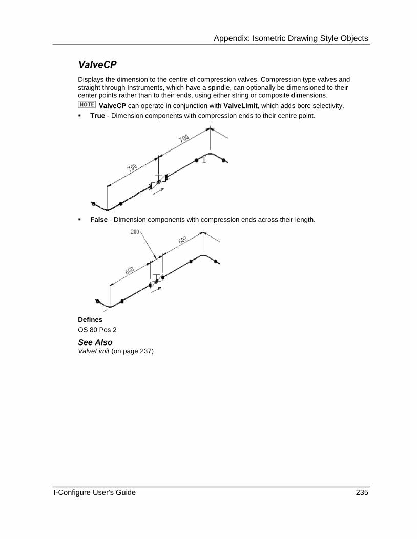
Appendix: Isometric Drawing Style Objects
I-Configure User's Guide 235
ValveCP
Displays the dimension to the centre of compression valves. Compression type valves and straight through Instruments, which have a spindle, can optionally be dimensioned to their center points rather than to their ends, using either string or composite dimensions.
ValveCP can operate in conjunction with ValveLimit, which adds bore selectivity.
True - Dimension components with compression ends to their centre point.
False - Dimension components with compression ends across their length.
Defines
OS 80 Pos 2
See Also ValveLimit (on page 237)

Appendix: Isometric Drawing Style Objects
236 I-Configure User's Guide
ValveFL
Displays the dimension to the centre of flanged valves. Flanged valves and straight through Instruments, which have a spindle, can optionally be dimensioned to their centre points rather than to their ends, using either string or composite dimensions.
ValveFL can operate in conjunction with ValveLimit, which adds bore selectivity.
True - Dimension components with flanged ends to their centre point.
False - Dimension components with flanged ends across their length.
Defines
OS 80 Pos 5
ValveHY
Displays the dimension to the centre of hygienic valves. Hygienic type valves and straight through instruments, which have a spindle, can optionally be dimensioned to their centre points rather than to their ends, using either string or composite dimensions. The default setting is False.
ValveHY can operate in conjunction with the ValveLimit property, which adds bore selectivity.

Appendix: Isometric Drawing Style Objects
I-Configure User's Guide 237
True - Dimension components with hygienic ends to their centre point.
False - Dimension components with hygienic ends across their length.
Defines
OS 80 Pos 7
See Also ValveLimit (on page 237)
ValveLimit
Provides the bore limit. Type a value in range 0-999. The default setting is 0.
If you set ValveLimit and the valve is above this limit, the software generates end dimensions.
0 - Dimension valves/instruments that have their end type set in ValveBW, ValveCP, and so on, to their centre point.
Value - Dimension valves/instruments that have their end type set in ValveBW, ValveCP, and so on, and have a bore equal to or less than the value set to their centre point. Value is in 1/16th of an inch or mm, depending on the bore units. For example, 32 x 1/16th is equivalent to 2” bore.
Defines
OS 81 Pos 1,2,3

Appendix: Isometric Drawing Style Objects
238 I-Configure User's Guide
ValvePL
Displays the dimension to the centre of plain valves. Plain-ended valves and straight through instruments, which have a spindle, can optionally be dimensioned to their centre points rather than to their ends, using either string or composite dimensions.
ValvePL can operate in conjunction with ValveLimit, which adds bore selectivity.
True - Dimension components with plain ends to their centre points
False - Dimension components with plain ends across their length.
Defines
OS 80 Pos 6
See Also ValveLimit (on page 237)

Appendix: Isometric Drawing Style Objects
I-Configure User's Guide 239
ValveSC
Displays the dimension to the centre of screwed valves. Screwed valves and straight through instruments, which have a spindle, can optionally be dimensioned to their centre points rather than to their ends, using either string or composite dimensions.
ValveSC can operate in conjunction with ValveLimit, which adds bore selectivity.
True - Dimension components with screwed ends to their centre points.
False - Dimension components with screwed ends across their length.
Defines
OS 80 Pos 3
See Also ValveLimit (on page 237)
ValveSW
Displays the dimension to the center of socket weld valves. Socket weld valves and straight through instruments, which have a spindle, can optionally be dimensioned to their center points rather than to their ends, using either string or composite dimensions. The default setting is False.
ValveSW can operate in conjunction with ValveLimit, which adds bore selectivity.

Appendix: Isometric Drawing Style Objects
240 I-Configure User's Guide
True - Dimension components with socket weld ends to their center points.
False - Dimension components with socket weld ends to be across their length.
Defines
OS 80 Pos 4
See Also ValveLimit (on page 237)
VertOption
Controls how vertical pipe positions are indicated on the isometric drawing.
Normal - Display normal vertical pipe dimensions, with elevations at intersection points when the level changes.

Appendix: Isometric Drawing Style Objects
I-Configure User's Guide 241
Suppressed - Suppress all vertical pipe dimensions, replaced by elevations in the form of text messages at all positions where dimensions would normally be output.
Elevation - Display vertical dimensions and elevations at all normal dimensioning positions.
Defines
OS 119
WeldDimensionAccuracy
Allows welds to be dimensioned to the nearest 10th mm.
Nearest mm - Dimension welds to the nearest mm.
Nearest 10th mm - Dimension welds to the nearest 10th mm. If the decimal place value is zero, the dimension is output in whole millimetres.
Defines
OS 119 Pos 8
WeldDimensioning
Controls the dimensioning of welds.
True - Dimension welds.
False - Suppress dimensioning of welds.
Defines
OS 119 Pos 7

Appendix: Isometric Drawing Style Objects
242 I-Configure User's Guide
Drawing.Format Object Sets options for the isometric drawing format, including text size and skew dimensions.
AngleAccuracy (on page 244)
AngleStyle (on page 244)
AngleType (on page 244)
AdditionalEnclosureStyle (on page 246)
AdditionalWeldEnclosure (on page 248)
AdditionalWeldEnclSpaces (on page 248)
AssemblyIDSequencing (on page 248)
BendRadius (on page 249)
BendRepresentation (on page 249)
ComponentLegLength (on page 249)
ComputeNozzleAxis (on page 250)
ConnectionIDCategory (on page 250)
CptAttributesEnclStyle (on page 245)
CptTagEnclStyle (on page 250)
CptTagsStyle (on page 250)
CurveThreshold (on page 251)
CutPieceNoLength (on page 251)
CutPieceEnclosureStyle (on page 251)
ElbowRadius (on page 252)
ElbowRepresentation (on page 252)
FabricationAssemblyIDEnclosure (on page 252)
FallCutOff (on page 253)
FallRepresentation (on page 253)
FlangeRotationStyle (on page 254)
FlowArrowScale (on page 254)
GhostGapDimension (on page 255)
InstIDEnclosureSize (on page 255)
InstIDEnclosureStyle (on page 255)
InstIdentification (on page 256)
InsulationStyle (on page 256)
MessageCircleEnclosure (on page 257)
MessageDiamondEnclosure (on page 257)
MessagePointedEnclosure (on page 258)
MessageRoundEnclosure (on page 259)
MessageSquareEnclosure (on page 259)
MessageTriangleEnclosure (on page 260)
MultiPortConnections (on page 261)
NorthArrowBox (on page 261)
OffshoreAssemblyIDEnclosure (on page 261)
OletBranchOrientationMessage (on page 262)
OrientationFrom (on page 262)
PartNoEnclosureStyle (on page 263)

Appendix: Isometric Drawing Style Objects
I-Configure User's Guide 243
PartNoEnclSize (on page 264)
PartNoSpaces (on page 265)
PartNoLength (on page 265)
PartNoVisible (on page 265)
SeparateSpoolUnion (on page 266)
ShowFlowArrows (on page 179)
SiteAssemblyIDEnclosure (on page 266)
SiteAssemblyIDEnclSize (on page 268)
SiteAssemblyIDs (on page 268)
SiteAssemblyIDsPerDrawing (on page 268)
SiteWeldsNotAssignedToSpools (on page 269)
SkewDimStandout (on page 269)
SkewDimStyle (on page 269)
SkewHatchCptGap (on page 270)
SkewHatchCutOff (on page 270)
SkewHatchDimText (on page 271)
skewHatching (on page 271)
SkewHatchPipeGap (on page 272)
SkewHatchSpacing (on page 272)
SkewInVerticalBranch (on page 273)
SkewMinCpts (on page 273)
SkewMixed (on page 274)
SkewOverall (on page 274)
SkewRepresentation (on page 275)
SkewAngleStyle (on page 276)
SkewTriangleRightAngleIndication (on page 276)
SpecBrkEnclosure (on page 276)
SpecBrkRepresentation (on page 277)
SpoolIDAllocation (on page 277)
SpoolIDContinuation (on page 277)
SpoolIDEnclosure (on page 277)
SpoolIDSize (on page 280)
SpoolIDEnclosureStyle (on page 280)
SpoolIDLength (on page 281)
SpoolDrawingID (on page 281)
SpoolIDType (on page 282)
SpoolPrefix (on page 282)
SupportIdentification (on page 283)
SupportTagEnclStyle (on page 283)
TapBranchInlineScale (on page 283)
TapBranchPipeScale (on page 284)
TapBranchSuppression (on page 284)
TeeCrossNS (on page 285)
TestIso (on page 285)
TextFont (on page 286)

Appendix: Isometric Drawing Style Objects
244 I-Configure User's Guide
TextSize (on page 286)
UserTextSize (on page 286)
TextWeight (on page 287)
TextWidth (on page 287)
TracingStyle (on page 287)
ReferenceNameStyle (on page 287)
CurvedPipeAngleStyle (on page 289)
CurvedPipeRadiusStyle (on page 289)
AngleAccuracy
Controls the accuracy at which angle information is output on the isometric drawing.
Default - Output all angles to ISOGEN default accuracy of 0.1 degrees with no trailing zeros. For example, 80.16 is output as 80.2 degrees, and 80.01 is output as 80 degrees.
Nearest Degree - Output angles to the nearest degree.
Nearest 10th Degree (1 decimal place) - Output angles to the nearest 0.1 degrees.
Nearest 100th Degree (2 decimal places) - Output angles to the nearest 0.01 degrees.
Defines
OS 67 Pos 4
AngleStyle
Controls the output of angle information for bends and elbows in the pipeline.
All - Output all angle information on the isometric (including angles that are exactly 90- and 180-degrees.)
All except 90/180 deg - Output all angle information on the isometric drawing except angles that are within 0.5-degrees of 90- and 180-degrees.
All except within 10th degree of 90/180 deg - Output angle information on the isometric drawing unless when rounded angles are within .1-degree of 90- and 180-degrees.
None - Suppress angle information on the isometric drawing.
Defines
OS 67 Pos 2
See Also AngleType (on page 244)

Appendix: Isometric Drawing Style Objects
I-Configure User's Guide 245
AngleType
Controls whether the angles output for bends and elbows are the included or deflected angle.
Deflected
Included
If set, AText -396 is combined with the angle information and displayed on the isometric drawing.
If not set (default), only the angle information is output.
Defines
OS 67 Pos 3
See Also AngleStyle (on page 244)

Appendix: Isometric Drawing Style Objects
246 I-Configure User's Guide
CptAttributesEnclStyle
Contains the text output to the Data Definition File (DDF) for the component attribute enclosure. Adheres to the following format:
Message-Type Attribute
Message-Types:
MESSAGE-POINTED
MESSAGE-ROUND
MESSAGE-TRIANGLE
MESSAGE-DIAMOND
MESSAGE-SQUARE
MESSAGE-CIRCLE
MESSAGE-UNBOXED
Attributes:
COMPONENT-NAME
COMPONENT-ATTRIBUTE1 to COMPONENT-ATTRIBUTE10
You can output attributes to the following:
Material list (Variable and UserDefined)
Printed material list
Material control file
Cut list report
Cut list file
AdditionalEnclosureStyle
Specifies the style for part number enclosures.
Type 1:
None - Display no enclosure style.
Type 1 Square
Type 1 Round

Appendix: Isometric Drawing Style Objects
I-Configure User's Guide 247
Type 1 Diamond
Type 2 - Use PartNoEnclosureStyle to define the style of end used with Type 2 additional enclosure.
Type 2 Square
Type 2 Round
Type 2 Diamond
PartNoSpaces needs to be set to control the number of blank spaces used.
If PartNoEnclosureStyle is set to Circle, Double Circle or Ellipse, then Type 2 AdditionalEnclosureStyle is switched off, as this uses the same setting.
For Type 2, the enclosure style for the box with the part numbers in it is defined using PartNoEnclosureStyle.
All pipe part numbers, which are usually output as messages along the pipe, are converted to arrowed out type messages.
Defines
OS 73 Pos 5
OS 76 Pos1
See Also PartNoEnclosureStyle (on page 263) PartNoSpaces (on page 265)

Appendix: Isometric Drawing Style Objects
248 I-Configure User's Guide
AdditionalWeldEnclosure
Controls special part number box for welds.
True - Display a special part number box for welds.
False - Suppress display of a special part number box for welds.
Welds must have part numbers and descriptions, and the MLType property must be set to Special.
Defines
OS 73 Pos 6,7
See Also AdditionalEnclosureStyle (on page 246) AdditionalWeldEnclSpaces (on page 248) PartNoEnclSize (on page 264) PartNoEnclosureStyle (on page 263) PartNoSpaces (on page 265) PartNovisible (on page 265)
AdditionalWeldEnclSpaces
Sets the number of spaces used when AdditionalWeldEnclosure is set to True.
Value - Specifies the number of spaces to be used. A default value of 2 is used if no value is set.
Defines
OS 73 Pos 6,7
See Also AdditionalEnclosureStyle (on page 246) AdditionalWeldEnclSpaces (on page 248) PartNoEnclSize (on page 264) PartNoEnclosureStyle (on page 263) PartNoSpaces (on page 265) PartNovisible (on page 265)
AssemblyIDSequencing
Controls how assembly identifiers are sequenced.
Combined - Sequence all assembly identifiers.
Category - Sequence assembly identifiers by category.
Defines
OS 79 Pos 7

Appendix: Isometric Drawing Style Objects
I-Configure User's Guide 249
BendRadius
Sets the bend radius in millimetres. Use this option only if you set the bend representation to round.
Value - Type a value in the range of 0-9. In the following example, the BendRadius is 8mm.
If you specify a value of 0, the software uses a default radius of 3mm.
See Also BendRepresentation (on page 249)
BendRepresentation
Defines how bends look on the isometric drawing.
Square
Round
ComponentLegLength
Specifies a plotted leg length for elbows, tees, and crosses. ComponentLegLength does not apply to fabricated (pulled) bends or set-on (stub-in) type tees or crosses.
Value - Specify the required leg length in whole millimetres. For example, for a 12 mm leg length, type 12.
Use this option with care, as it can produce undesirable results on the drawing. The maximum suggested value is 18 (18 mm), and the minimum suggested value is 6 (6 mm).
If you set the Value to 0, the software uses a default value of 9 mm.
Defines
OS 95 Pos 1

Appendix: Isometric Drawing Style Objects
250 I-Configure User's Guide
ComputeNozzleAxis
Controls the calculation of Nozzle axes directions and insertion of this information into the PCF (Piping Component File) when using the Pcfgen program.
True - Nozzle axis direction calculated and inserted into the PCF.
False - No calculation of Nozzle axis direction calculated or output to the PCF.
Currently not in use - leave set at False.
Defines
OS 111 Pos 2
ConnectionIDCategory
Controls which category of end connections is assigned an identifier.
All - Assign an identifier to all end connections.
Fabrication - Assign an identifier only to Fabrication end connections.
Erection - Assign an identifier only to Erection end connections.
Offshore - Assign an identifier only Offshore end connections.
Erection and Offshore - Assign an identifier only to Erection and Offshore end connections.
Defines
OS 79 Pos 8
CptTagEnclStyle
Controls the enclosure shapes used for components if CptTagsStyle is set to Boxed.
Square-ended box
Diamond-ended box
Round-ended box
Triangular
Diamond
Rectangular
Circular
Elliptical
Hexagonal
Defines
OS 60 Pos 3
See Also CptTagsStyle (on page 250)

Appendix: Isometric Drawing Style Objects
I-Configure User's Guide 251
CptTagsStyle
Defines the style for tag numbers on inline items.
None - Suppress plotting of tags/names.
Boxed - Plot and box in tags/names.
Unboxed - Plot tags/names without boxing in.
Tagging of pipe and pipeline elements made from pipe is not supported.
For instruments, see InstIDEnclosureStyle (on page 255).
Defines
OS 60 Pos 1
See Also CptTagEnclStyle (on page 250)
CurveThreshold
Defines the minimum radius at which bends are output as curved pipe on the isometric drawing.
Value - Type a value in the range of 0-99.
Curved pipe can be drawn only in primary planes.
CutPieceNoLength
Sets a fixed (1-9 characters or variable) length for part numbers.
Value - Specify the fixed length.
Defines
OS 72 Pos 2
See Also CutPieceEnclosureStyle (on page 251)
CutPieceEnclosureStyle
Controls the shape of the enclosure used to surround the cut piece numbers on the isometric.
<n> Default
Circle
Diamond
Diamond Ends
Double Circle
Double Ellipse
Ellipse
Hexagon Ends
Round Ends
Square Ends
Triangle
Defines
OS 2 Pos 7

Appendix: Isometric Drawing Style Objects
252 I-Configure User's Guide
ElbowRadius
Controls the radius depiction (in millimetres) on the isometric drawing for elbows. Acceptable values are in range 3mm to 9mm.
Value - Specify the elbow radius. In the following illustration, ElbowRadius is set at 4.5mm.
Use this option only if you set ElbowRepresentation to Round.
The default radius used for elbows is 3mm.
See Also ElbowRepresentation (on page 252)
ElbowRepresentation
Defines how elbows look on the isometric drawing.
Square
Round
FabricationAssemblyIDEnclosure
Controls the enclosure style for Fabrication assembly identifiers output on the isometric drawing.
None - Display assembly identifiers with no box enclosure.
Diamond Ended - Display assembly identifiers in a diamond-ended box enclosure.
Round Ended - Display assembly identifiers in a round-ended box enclosure.
Triangle - Display assembly identifiers in a triangular-shaped enclosure.
Diamond - Display assembly identifiers in a diamond-shaped enclosure.
Square Ended - Display assembly identifiers in a square-ended box enclosure.
Circle - Display assembly identifiers in a circular enclosure.
Suppress - Suppress the display of assembly identifiers.
Double Circle - Display assembly identifiers in a circular-shaped enclosure inside another circle.
Ellipse - Display assembly identifiers in an elliptical-shaped enclosure.
Defines
OS 79 Pos 5

Appendix: Isometric Drawing Style Objects
I-Configure User's Guide 253
FallCutOff
Defines the minimum slope treated as a fall. Slopes steeper than the cut-off value are shown with a 2D or 3D box or triangle skew indication as appropriate.
0 - Use the default for 5° angle cut-off or its equivalent depending upon the type of indication selected by FallRepresentation.
Value - Define a cut-off number to suit the type of indication selected by FallRepresentation.
For fall cut off of 5 Degrees, type 5 or 0.
For fall cut off of 1:11 Ratio, type 11.
For fall cut off of 9 Percent, type 9.
For fall cut off of 5 Grads, type 5.
For fall cut off of 1" Per foot, type 1.
For fall cut off of 88 mm per metre, type 88.
Always set FallCutOff to 0 when sloping pipeline indication has been suppressed by FallRepresentation.
Defines
OS 20
See Also FallRepresentation (on page 253)
FallRepresentation
Specifies how sections of falling pipelines (downward slopes) are indicated on the isometric drawing. This option determines the method of how the fall value is to be indicated numerically on the isometric, as specified by one of the options shown below.
None - Suppress falling line indication.
D deg - Output angle to nearest degree.
D.d deg - Output angle to nearest 1/10th degree.
D.dd deg - Output angle to nearest 1/100th degree.
deg.min - Output angle in degrees and minutes.
G grad - Output gradient to nearest grad.
G.g grad - Output gradient to nearest 1/10th grad.
G.gg grad -Output gradient to nearest 1/100th grad.
Incline~1/16th"/ft - Output incline to nearest 16th of an inch per foot.
Incline~1/100"/ft - Output incline to nearest 100th of an inch per foot.
Incline~1mm/m - Output incline to nearest mm per metre.
Incline~5mm/m - Output incline to nearest 5 mm per metre.
Incline~10mm/m - Output incline to nearest 10 mm per metre.
P% - Output percentage to nearest whole value.
P.p% - Output percentage to nearest 1 decimal place.

Appendix: Isometric Drawing Style Objects
254 I-Configure User's Guide
P.pp% - Output percentage to nearest 2 decimal place.
Ratio~5 (>1:30) -Output ratio to nearest 5 when greater than 1:30.
Ratio~5 (>1:100) - Output ratio to nearest 5 when greater than 1:100.
Ratio~1 - Output ratio to nearest 1.
Defines
OS 19
See Also FallCutOff (on page 253)
FlangeRotationStyle
Specifies the style of the enclosure box for flange rotation angles on the isometric drawing, when ShowFlangeRotation is set to True.
No box - Output un-boxed angle output.
Diamond ends - Output a diamond-ended enclosure box.
Round ends - Output a round-ended enclosure box.
Square ends - Output a square- ended enclosure box.
Defines
OS 124 Pos 2
See Also ShowFlangeRotation (on page 178)
FlowArrowScale
Scales flow arrows that are plotted directly on the pipe. Flow arrows are used to show the flow direction of fluid or gas in the pipeline.
Value - Plot pipeline flow arrows at an alternative scale factor (default 8) in the range value 5 to 15 (value 5 produces smaller arrows, 15 larger).
You can generate this type of flow arrow only if the relevant information is included in the input pipeline data file.
You can also use a separate type of flow arrow, which is plotted alongside in-line fittings, either as well as or instead of, the flow arrow annotation output on pipe.
Defines
OS 112 Pos 1,2
See Also ShowCptFlowArrows (on page 178)

Appendix: Isometric Drawing Style Objects
I-Configure User's Guide 255
GhostGapDimension
Controls the plotted length of a ghost gap element. A ghost gap element is a physical gap on the plotted isometric that can be used when generating individual pipeline isometrics, or as a link between related, but unconnected, pipelines on a system type isometric. The default setting is 0.
0 - Use the normal minimum gap as controlled by ISOGEN.
Value - Specify a user-defined minimum gap dimension in whole millimeters.
The smallest allowable value is 18 mm, and the largest allowable value is 60 mm.
The software defaults to using the appropriate maximum value if it detects a setting outside these limits.
Defines
OS 110
InstIDEnclosureSize
Specifies the size of the enclosure for instrument text. You can choose 1 through 4 characters on each of the two available lines within an instrument balloon, or you can specify no balloon.
No Balloon- Suppress plotting of a balloon around the instrument name.
1 character - Plot a balloon size at least 1 character on each line.
2 character - Plot a balloon size at least 2 characters on each line.
3 character - Plot a balloon size at least 3 characters on each line.
A two line name output is derived by inputting a $ character in the name at the point a new-line is required, such as CV$101.
4 character - Plot a balloon size at least 4 characters on each line.
5 character - Plot a balloon size at least 5 characters on each line.
A variety of other box type enclosures is available by using InstIDEnclosureStyle.
Defines
OS 123 Pos 1

Appendix: Isometric Drawing Style Objects
256 I-Configure User's Guide
InstIDEnclosureStyle
Specifies the shape of the instrument name box.
No Box - Revert to using the setting for InstIDEnclosureSize .
Diamond - Display a diamond-ended box enclosure.
Round - Display a round-ended box enclosure.
Triangular - Display a triangle-shaped enclosure.
Diamond - Display a diamond-shaped enclosure.
Square - Display a square-ended box enclosure.
Circle - Display a circular-shaped enclosure.
Ellipse - Display an elliptical-shaped enclosure.
Hexagon - Display a hexagonal-shaped enclosure.
To reduce the chances of these enclosures becoming quite large, especially the diamond and triangle enclosures, limit the display to only 2 or 3 characters.
Defines
OS 123 Pos 3
See Also InstIDEnclosureSize (on page 255)
InstIdentification
Specifies whether to use the instrument tag or item code in the material list or any material control file that is generated. Typically, 3D design systems have parameters for both the instrument name (tag) and the specification reference (Item code), but only one of these can be selected for output.
Use Tag - Output the default for the instrument name (tag).
Use Item Code - Output the instrument item code.
Defines
OS 59
InsulationStyle
Specifies whether to show insulation along pipe only or along pipe and components.
None - Suppress insulation indication.
Alongside Pipe - Plot dashed insulation lines alongside pipe only, with a gap of 1 mm.
Alongside Pipe and Components - Plot dashed insulation lines alongside pipe and all components, both with a 1 mm gap.
Defines
OS 61

Appendix: Isometric Drawing Style Objects
I-Configure User's Guide 257
MessageCircleEnclosure
Controls the physical size of the circle enclosure used to contain user input messages.
This is achieved by specifying a mixture of new line and blank character indicators that are used by the software to pad-out the normal message record to effectively increase the size of the enclosure. The size of the text (set by TextSize) displayed within any increased size enclosure is not increased in size.
The data string associated with each identifier consists of a combination of @, $ and ? characters.
The @ character signals a blank (space) requirement.
The $ character signals a new line requirement.
The ? character indicates where the actual data from the declared record is located in the padded-out record.
Setting the value to the text string @@?@@ increases the message enclosure as shown in the following illustration:
Ideally, the message enclosure should only contain two or three characters, and should also be used with care, as a large circle message considerably affects the isometric representation.
See Also TextSize (on page 286)
MessageDiamondEnclosure
Controls the physical size of the diamond enclosure used to contain user input messages.
This is achieved by specifying a mixture of new line and blank character indicators that are used by the program to pad- out the normal message record to effectively increase the size of the enclosure. The size of the text (set by TextSize) displayed within any increased size enclosure is not increased in size.
The data string associated with each identifier consists of a combination of @, $ and ? characters.
The @ character signals a blank (space) requirement.
The $ character signals a new line requirement.
The ? character indicates where the actual data from the declared record is be located in the padded-out record.

Appendix: Isometric Drawing Style Objects
258 I-Configure User's Guide
Setting the value to the text string @@?@@ increases the message enclosure, as shown in the following illustration:
Ideally, the message enclosure should only contain two or three characters, and should also be used with care, as a large message enclosure considerably affects the isometric representation.
See Also TextSize (on page 286)
MessagePointedEnclosure
Controls the physical size of the pointed-ended enclosure used to contain user input messages.
This is achieved by specifying a mixture of new line and blank character indicators that are used by the program to pad- out the normal message record to effectively increase the size of the enclosure. The size of the text (set by TextSize) displayed within any increased size enclosure is not increased in size.
The data string associated with each identifier consists of a combination of @, $ and ? characters.
The @ character signals a blank (space) requirement.
The $ character signals a new line requirement.
The ? character indicates where the actual data from the declared record is be located in the padded-out record.
Setting the value to the text string @@?@@ increases the message enclosure as shown in the following illustration:
Ideally, use the message enclosure with care, as a large message enclosure considerably affects the isometric representation.
See Also TextSize (on page 286)

Appendix: Isometric Drawing Style Objects
I-Configure User's Guide 259
MessageRoundEnclosure
Controls the physical size of the round-ended enclosure used to contain user input messages.
This is achieved by specifying a mixture of new line and blank character indicators that are used by the program to pad- out the normal message record to effectively increase the size of the enclosure. The size of the text (set by TextSize) displayed within any increased size enclosure is not increased in size.
The data string associated with each identifier consists of a combination of @, $ and ? characters.
The @ character signals a blank (space) requirement.
The $ character signals a new line requirement.
The ? character indicates where the actual data from the declared record is be located in the padded-out record.
Setting the value to the text string @@?@@ increases the message enclosure as shown in the following illustration:
Use the message enclosure with care, as a large message enclosure considerably affects the isometric representation.
See Also TextSize (on page 286)
MessageSquareEnclosure
Controls the physical size of the square enclosure used to contain user input messages.
This is achieved by specifying a mixture of new line and blank character indicators that are used by the program to pad- out the normal message record to effectively increase the size of the enclosure. The size of the text (set by TextSize) displayed within any increased size enclosure is not increased in size.
The data string associated with each identifier consists of a combination of @, $ and ? characters.
The @ character signals a blank (space) requirement.
The $ character signals a new line requirement.
The ? character indicates where the actual data from the declared record is be located in the padded-out record.

Appendix: Isometric Drawing Style Objects
260 I-Configure User's Guide
Setting the value to the text string @@?@@ increases the message enclosure, as shown in the following illustration:
Use the message enclosure with care, as a large message enclosure considerably affects the isometric representation.
See Also TextSize (on page 286)
MessageTriangleEnclosure
Controls the physical size of the triangle enclosure used to contain user input messages.
This is achieved by specifying a mixture of new line and blank character indicators that are used by the program to pad- out the normal message record to effectively increase the size of the enclosure. The size of the text (set by TextSize) displayed within any increased size enclosure is not increased in size.
The data string associated with each identifier consists of a combination of @, $ and ? characters.
The @ character signals a blank (space) requirement.
The $ character signals a new line requirement.
The ? character indicates where the actual data from the declared record is be located in the padded-out record.
Setting the value to the text string @@?@@ increases the message enclosure, as shown in the following illustration:
Ideally, the message enclosure should only contain two or three characters, and should also be used with care, as a large circle message considerably affects the isometric representation.
See Also TextSize (on page 286)

Appendix: Isometric Drawing Style Objects
I-Configure User's Guide 261
MultiPortConnections
Controls the connection leg depiction of multi-port components.
All Dotted - Display dotted connection lines on all multi-port connections.
Dotted for Clarity - Display dotted connection lines only when necessary for picture clarity, such as when two or more ports are positioned on the same side with attached pipe work running parallel to each other.
Not shown - Suppress the display of dotted connection lines shown.
Defines
OS 95 Pos 5
NorthArrowBox
Controls whether the north arrow, as specified by NorthDirection, is displayed in an enclosing box.
True - Display the north arrow in an enclosing box.
False - Suppress the display of the north arrow in an enclosing box.
Defines
OS 42 Pos 1
See Also NorthDirection (on page 193)
OffshoreAssemblyIDEnclosure
Controls the enclosure style for Offshore assembly identifiers output on the isometric drawing.
None - Display assembly identifiers in no box enclosure.
Diamond Ended - Display assembly identifiers in a diamond-ended box enclosure.
Round Ended - Display assembly identifiers in a round-ended box enclosure.
Triangle - Display assembly identifiers in a triangular-shaped enclosure.
Diamond - Display assembly identifiers in a diamond-shaped enclosure.
Square Ended - Display assembly identifiers in a square-ended box enclosure.
Circle - Display assembly identifiers in a circular enclosure.
Suppress - Suppress the display of assembly identifiers.
Double Circle - Display assembly identifiers in a circular-shaped enclosure inside another circle.
Ellipse - Display assembly identifiers in an elliptical-shaped enclosure.
Defines
OS 79 Pos 6

Appendix: Isometric Drawing Style Objects
262 I-Configure User's Guide
OletBranchOrientationMessage
Controls the output of an orientation message on undeveloped olet branches that are in primary directions.
Create Orientation Message - Output an orientation message on undeveloped olet branches in a primary direction.
No Message - Suppress output of an orientation message on the isometric drawing.
Defines
OS 70 Pos 4
OrientationFrom
Controls the output of Skew orientation.
Previous Position - Output the orientation direction message showing rotation relative to previous position.
Primary Direction - Output the orientation direction message showing rotation from primary direction.
Defines
OS 70 Pos 3

Appendix: Isometric Drawing Style Objects
I-Configure User's Guide 263
PartNoEnclosureStyle
Specifies the part number enclosure box shape.
None - No enclosure box. Only plots part numbers.
Square Ends
Round Ends
Diamond Ends
Circle
Double Circle

Appendix: Isometric Drawing Style Objects
264 I-Configure User's Guide
Ellipse
The size at which the circle, double circle and ellipse is drawn is controlled by PartNoEnclosureSize (default 2 characters), which defines the minimum size for the enclosure. If there are more characters than the value set, the enclosure dynamically adjusts to accommodate.
Defines
OS 76 Pos 1 and 2
See Also PartNoEnclSize (on page 264)
PartNoEnclSize
Controls the number of characters used for the size of circle, double circle and eclipse enclosure style. The default is 2, and the valid entries are from 1 to 8 characters, or set to Variable size, which dynamically sizes the enclosure.
The following example shows the default size of 2 used for the circle enclosure style:
The number of characters defines the minimum size that the circle, double circle and ellipse is drawn at. If there are more characters than the value that is defined, the enclosure dynamically adjusts to suit. If the option is set to Variable size, this allows the circle, double circle and ellipse to be smaller than the default of 2 characters, but again dynamically adjust to suit the number of characters.
Defines
OS 76 Pos 3
See Also AdditionalEnclosureStyle (on page 246) PartNoEnclosureStyle (on page 263) PartNoSpaces (on page 265) PartNoVisible (on page 265) AdditionalWeldEnclSpaces (on page 248) AdditionalWeldEnclosure (on page 248)

Appendix: Isometric Drawing Style Objects
I-Configure User's Guide 265
PartNoSpaces
Sets the number of spaces used in the Type 1 and Type 2 part number boxes specified by AdditionalEnclosureStyle.
Value - Specify the number of spaces to be used. A default value of 2 is used if no value is set.
Defines
OS 73 Pos 1 and 2 or
OS 73 Pos 3 and 4
See Also AdditionalEnclosureStyle (on page 246) PartNoEnclosureStyle (on page 263) PartNoVisible (on page 265) AdditionalWeldEnclSpaces (on page 248) AdditionalWeldEnclosure (on page 248)
PartNoLength
Sets a fixed length for part numbers (1-9 characters or variable).
Value - Specify a fixed length for part numbers.
Defines
OS 76 Pos 4
See Also AdditionalEnclosureStyle (on page 246) PartNoEnclosureStyle (on page 263) PartNoVisible (on page 265) AdditionalWeldEnclSpaces (on page 248) AdditionalWeldEnclosure (on page 248)
PartNoVisible
Suppresses the plotting of part numbers and associated enclosure boxes on the drawing.
True - Display part numbers on the isometric drawing.
False - Suppress the display of part numbers on the isometric drawing.
Defines
OS 76 Pos 1
See Also AdditionalEnclosureStyle (on page 246) PartNoEnclosureStyle (on page 263) PartNoSpaces (on page 265) AdditionalWeldEnclSpaces (on page 248) AdditionalWeldEnclosure (on page 248)

Appendix: Isometric Drawing Style Objects
266 I-Configure User's Guide
SeparateSpoolUnion
Controls spool break points at unions.
True - A fabrication union connecting fabrication components does not create separate spools.
False - A fabrication union connecting fabrication components creates separate spools.
Defines
OS 39 Pos 7
SiteAssemblyIDEnclosure
Controls the enclosure style used for site assemblies on the isometric drawing.
None - Display no box enclosure.
Diamond - Display a diamond-ended box enclosure.
Round - Display a round-ended box enclosure.
Triangular - Display a triangular-shaped enclosure.

Appendix: Isometric Drawing Style Objects
I-Configure User's Guide 267
Diamond - Display a diamond-shaped enclosure.
Rectangular - Display a rectangular-shaped enclosure.
Circular - Display a circular-shaped enclosure.
Double Circle - Display a circular-shaped enclosure inside another circle.
Ellipse - Display an elliptical-shaped enclosure.
The site assembly uses AText -478, default J--such as J1 or JA--to prefix the flange assembly identification.
The size that the circle, double circle and ellipse is drawn at is controlled by SiteAssemblyIDEnclSize (default 2 characters) which defines the minimum size for the enclosure. If there are more characters than the value set, the enclosure dynamically adjusts to suit.
Defines
OS 79 Pos 3
See Also SiteAssemblyIDEnclSize (on page 268) SiteAssemblyIDs (on page 268)

Appendix: Isometric Drawing Style Objects
268 I-Configure User's Guide
SiteAssemblyIDEnclSize
Controls the number of characters used for the size of circle, double circle and ellipse enclosure style. The default is 2, and the valid entries are from 1 to 8 characters or set to Variable size, which dynamically sizes the enclosure.
The following example shows the default size of 2 used for a circle style enclosure:
The number of characters defines the minimum size that the circle, double circle and ellipse is drawn at. If there are more characters than the value set, the enclosure is dynamically adjusted to suit. Setting the size to Variable size, allows the circle, double circle and ellipse to be smaller than the default of 2 characters, but again dynamically adjusts to suit the number of characters.
Defines
OS 79 Pos 9
See Also SiteAssemblyIDEnclosure (on page 266) SiteAssemblyIDs (on page 268) SiteAssemblyIDsPerDrawing (on page 268)
SiteAssemblyIDs
Controls site assembly information displayed on the isometric drawing.
Off - Suppress display of flange assembly identification.
Numeric - Display numeric flange assembly identification.
Alphabetic - Display alphabetic flange assembly identification.
Defines
OS 79 POS 1
SiteAssemblyIDsPerDrawing
Controls whether site assemblies are numbered per drawing or per pipeline.
True - Number flange assembly identification per drawing.
False - Number flange assembly identification per pipeline.
Defines
OS 79 Pos 2

Appendix: Isometric Drawing Style Objects
I-Configure User's Guide 269
SiteWeldsNotAssignedToSpools
By default, site welds are assigned to spools if they are adjoining.
True - Suppress assignment of site welds to adjoining spools.
False - Assign site welds to adjoining spools.
Defines
OS 83 Pos 1
SkewDimStandout
Controls the dimension line standout distance used on boxed or triangle skew dimensions.
0 - Use the dimension line standout setting defined in StandOutComposite, except when SkewDimStyle is set to Triangle - Alternative, in which case the default dimension position is 4 mm.
Value - Specify the value (real number) used as an alternative dimension line standout in mm or inches, depending on the setting of the drawing units. Used when SkewDimStyle is set to Triangle - Skew standout.
Defines
OS 100
See Also SkewDimStyle (on page 269) StandOutComposite (on page 223)
SkewDimStyle
Specifies how skewed pipe sections are drawn on the isometric, along with the form of skew dimensioning to be used.
Box - normal standout - Depict skew box with normal dimensioning.
Triangle - normal standout - Depict skew triangle with normal dimensioning.
Triangle - skew standout - Depict skew triangle with normal dimensioning. Uses the value set in SkewDimStandout.
Triangle - alternative - Depict skew triangle with alternative dimensioning. Actual dimensions are positioned close to the sides of triangle with no witness lines.
Defines
OS 99 Pos 1
See Also SkewDimStandout (on page 269) SkewHatchCptGap (on page 270) SkewHatchCutOff (on page 270) SkewHatchDimText (on page 271) SkewHatching (on page 271) SkewHatchPipeGap (on page 272) SkewHatchSpacing (on page 272) SkewInVerticalBranch (on page 273) SkewMinCpts (on page 273) SkewOverall (on page 274) SkewRepresentation (on page 275) SkewAngleStyle (on page 276)

Appendix: Isometric Drawing Style Objects
270 I-Configure User's Guide
SkewHatchCptGap
Specifies the gap left unhatched for inline components.
0 - Use a gap local to pipeline of 2.5 mm.
Value - Specify value (real number) as an alternative gap in mm or inches, depending on the setting of the drawing units in the Options dialog box.
Defines
OS 102 Pos 3,4
See Also SkewDimStandout (on page 269) SkewDimStyle (on page 269) SkewHatchCutOff (on page 270) SkewHatchDimText (on page 271) SkewHatching (on page 271) SkewHatchPipeGap (on page 272) SkewHatchSpacing (on page 272) SkewInVerticalBranch (on page 273) SkewMinCpts (on page 273) SkewOverall (on page 274) SkewRepresentation (on page 275) SkewAngleStyle (on page 276) SpecBrkRepresentation (on page 277)
SkewHatchCutOff
Controls the maximum length in whole mm or inches, depending on the setting of the drawing units in the Options dialog box, of the hatching lines to be plotted. Type a value in the range 0-99.
Blank - Use the default for no hatch line cut-off value. All triangles are fully hatched.
Value - Specify the value that equals the hatch line cut-off length. For example, type 25 for a 25 mm cut-off value. In this case, hatch lines in excess of 25 mm long are not be plotted. This gives a partial hatched effect.
Defines
OS 101 Pos 3,4
See Also SkewDimStandout (on page 269) SkewDimStyle (on page 269) SkewHatchCptGap (on page 270) SkewHatchDimText (on page 271) SkewHatching (on page 271) SkewHatchPipeGap (on page 272) SkewHatchSpacing (on page 272) SkewInVerticalBranch (on page 273) SkewMinCpts (on page 273) SkewOverall (on page 274) SkewRepresentation (on page 275) SkewAngleStyle (on page 276) SpecBrkRepresentation (on page 277)

Appendix: Isometric Drawing Style Objects
I-Configure User's Guide 271
SkewHatchDimText
Controls the physical size of the un-hatched gaps (white areas) to be left local to dimensions or text that fall within any skew triangle hatching.
Blank - Use the default for gap local to dimensions / text of 1.5mm.
Value - Specify the value used as an alternative gap. You can express the value in mm or inches, depending on the setting of the drawing units in the Options dialog box.
Defines
OS 102 Pos 5,6
See Also SkewDimStandout (on page 269) SkewDimStyle (on page 269) SkewHatchCptGap (on page 270) SkewHatchCutOff (on page 270) SkewHatching (on page 271) SkewHatchPipeGap (on page 272) SkewHatchSpacing (on page 272) SkewInVerticalBranch (on page 273) SkewMinCpts (on page 273) SkewOverall (on page 274) SkewRepresentation (on page 275) SkewAngleStyle (on page 276) SpecBrkRepresentation (on page 277)
SkewHatching
Specifies whether skew hatching is on or off.
True - Turn on skew hatching.
False - Turn off skew hatching.
Defines
OS 101 Pos 1
See Also SkewDimStandout (on page 269) SkewDimStyle (on page 269) SkewHatchCptGap (on page 270) SkewHatchCutOff (on page 270) SkewHatchDimText (on page 271) SkewHatchPipeGap (on page 272) SkewHatchSpacing (on page 272) SkewInVerticalBranch (on page 273) SkewMinCpts (on page 273) SkewOverall (on page 274) SkewRepresentation (on page 275) SkewAngleStyle (on page 276) SpecBrkRepresentation (on page 277)

Appendix: Isometric Drawing Style Objects
272 I-Configure User's Guide
SkewHatchPipeGap
Controls the physical size of the unhatched gaps (white space) to be left local to the pipeline. The default value is 2.5 mm.
0 - Use the default value for the gap local to pipeline.
Value - Specify the value (in the range 0-10) used for the alternative gap. You can type the value in mm or inches, depending on the setting of the drawing units in the Options dialog box.
Defines
OS 102 Pos 1, 2
See Also SkewDimStandout (on page 269) SkewDimStyle (on page 269) SkewHatchCptGap (on page 270) SkewHatchCutOff (on page 270) SkewHatchDimText (on page 271) SkewHatching (on page 271) SkewHatchSpacing (on page 272) SkewInVerticalBranch (on page 273) SkewMinCpts (on page 273) SkewOverall (on page 274) SkewRepresentation (on page 275) SkewAngleStyle (on page 276) SpecBrkRepresentation (on page 277)
SkewHatchSpacing
Controls the spacing of the hatching lines used in hatched triangles.
Value - Specify the value (in range 0-10) that equals the alternative hatch line spacing. Type a value in mm or inches, depending on the setting of the drawing units in the Options dialog box.
Defines
OS 101 Pos 1, 2
See Also SkewDimStandout (on page 269) SkewHatchCptGap (on page 270) SkewHatchCutOff (on page 270) SkewHatchDimText (on page 271) SkewHatching (on page 271) SkewHatchPipeGap (on page 272) SkewInVerticalBranch (on page 273) SkewMinCpts (on page 273) SkewOverall (on page 274) SkewRepresentation (on page 275) SkewAngleStyle (on page 276) SpecBrkRepresentation (on page 277)

Appendix: Isometric Drawing Style Objects
I-Configure User's Guide 273
SkewInVerticalBranch
Controls the drawing depiction method used when a vertical branch connection is made to a sloping (falling) pipeline using a special zero length bend component. The default setting is True.
This special bend (which has no length) is used to carry the angle between the vertical branch and the sloping pipeline. Two drawing methods are available. One shows a small 2D skew box section between the branch and the main pipe, while the other does not.
Where olets are used in such cases, a text message indicates the orientation direction if the branch is not developed.
True - Show the short tee branch leg section of pipe skewed. Olets have an orientation message instead of a skewed section. Both are dimensioned separately to the connecting pipe.
False - For no separate skew sections, the vertical branch is connected straight into the main pipe. Olets do not have an orientation message. Both are included in a single inclusive dimension.
In both cases the angle between the vertical branch and the sloping (falling) pipeline will be indicated.
Defines
OS 68
See Also SkewDimStandout (on page 269) SkewDimStyle (on page 269) SkewHatchCptGap (on page 270) SkewHatchCutOff (on page 270) SkewHatchDimText (on page 271) SkewHatching (on page 271) SkewHatchPipeGap (on page 272) SkewHatchSpacing (on page 272) SkewMinCpts (on page 273) SkewOverall (on page 274) SkewRepresentation (on page 275) SkewAngleStyle (on page 276) SpecBrkRepresentation (on page 277)

Appendix: Isometric Drawing Style Objects
274 I-Configure User's Guide
SkewMinCpts
Optionally permits simple skewed branch legs to have the normal skew box/triangle enclosure suppressed and replaced by a single pipe length dimension and a text message giving the branch orientation. Acceptable range of values is 0-99. The default value is 0.
When used to suppress the normal box enclosure, the value set represents the maximum number of fittings permitted in the branch. Branches found to contain more fittings than this are drawn with the normal skew box/triangle enclosure.
0 - Draw all branches with normal skew box/triangle depiction.
Value - Suppress skew box/triangle depiction on branch legs whose number of components is less than or equal to the value set, and output an orientation message.
This facility is only available on straight through branches. Any change in direction along the branch automatically causes the program to default to normal skew box/triangle output.
Defines
OS 70
SkewMixed
Shows 3D skew boxes and 2D skew triangles.
True - For mixture of skew indication types--3D skews are indicated with boxes, and 2D skews are indicated with triangles.
False - All skew indications similar, as defined by SkewDimStyle.
Defines
OS 99 Pos 2
See Also SkewDimStandout (on page 269) SkewDimStyle (on page 269) SkewHatchCptGap (on page 270) SkewHatchCutOff (on page 270) SkewHatchDimText (on page 271) SkewHatching (on page 271) SkewHatchPipeGap (on page 272) SkewHatchSpacing (on page 272) SkewInVerticalBranch (on page 273) SkewMinCpts (on page 273) SkewOverall (on page 274) SkewRepresentation (on page 275) SkewAngleStyle (on page 276) SpecBrkRepresentation (on page 277)

Appendix: Isometric Drawing Style Objects
I-Configure User's Guide 275
SkewOverall
Controls how skew pipe sections containing branch connections are depicted in terms of the skew indication on the isometric drawing. Such skews may be shown as either a single, overall enclosure or as a series of separate box or triangle enclosures.
Individual - Depict skews with a series of separate box or triangle enclosures, one enclosure per branch.
Overall - Depict a single overall skew.
Defines
OS 97
See Also SkewDimStandout (on page 269) SkewHatchCptGap (on page 270) SkewHatchCutOff (on page 270) SkewHatchDimText (on page 271) SkewHatching (on page 271) SkewHatchPipeGap (on page 272) SkewHatchSpacing (on page 272) SkewInVerticalBranch (on page 273) SkewMinCpts (on page 273) SkewRepresentation (on page 275) SkewAngleStyle (on page 276) SpecBrkRepresentation (on page 277)
SkewRepresentation
Controls the method used to depict sloping (falling) sections of a pipeline that are skewed in the horizontal plane.
3D box - Show the full 3D box or triangle.
2D Skew + Fall - Show the 2D skew box or triangle plus fall indicator.
Defines
OS 67
See Also SkewDimStandout (on page 269) SkewDimStyle (on page 269) SkewHatchCptGap (on page 270) SkewHatchCutOff (on page 270) SkewHatchDimText (on page 271) SkewHatching (on page 271) SkewHatchPipeGap (on page 272) SkewHatchSpacing (on page 272) SkewInVerticalBranch (on page 273) SkewMinCpts (on page 273) SkewOverall (on page 274) SkewAngleStyle (on page 276) SpecBrkRepresentation (on page 277)

Appendix: Isometric Drawing Style Objects
276 I-Configure User's Guide
SkewTriangleRightAngleIndication
Controls the output of a right angle indicator on skew triangles.
True - Output right angle indicators on skew triangles.
False - Suppress output of right angle indicators on skew triangles.
Defines
OS 99 Pos 4
SkewAngleStyle
Controls the output of skew angles on skewed section of pipeline.
Both Angles With Arrowheads - Display both skew angles with arrow heads on the arc radius.
Both Angles Without Arrowheads - Display both skew angles without arrow heads on the arc radius.
Not Shown - Suppress output of skew angles.
With Arrowheads - Display a single skew angle with arrow heads on the arc radius.
Without Arrowheads - Display a single skew angle without arrow heads on the arc radius.
Defines
OS 99 Pos 3
See Also SkewDimStandout (on page 269) SkewDimStyle (on page 269) SkewHatchCptGap (on page 270) SkewHatchCutOff (on page 270) SkewHatchDimText (on page 271) SkewHatching (on page 271) SkewHatchPipeGap (on page 272) SkewHatchSpacing (on page 272) SkewInVerticalBranch (on page 273) SkewMinCpts (on page 273) SkewOverall (on page 274) SkewRepresentation (on page 275) SpecBrkRepresentation (on page 277)
SpecBrkEnclosure
Controls the shape of the enclosure that surrounds the indication of a specification break (specification change) on the isometric drawing.
None - Suppress the display of an enclosure around the specification break reference on the isometric drawing.
Square Ended - Display a square-shaped box enclosure around the specification break reference on the isometric drawing.
Diamond Ended - Display a diamond-shaped enclosure around the specification break reference on the isometric drawing.
Round Ended - Display a round-ended box enclosure around the specification break reference on the isometric drawing.

Appendix: Isometric Drawing Style Objects
I-Configure User's Guide 277
Hexagonal Ended - Display a hexagonally-shaped enclosure around the specification break reference on the isometric drawing.
Defines
OS 114 Pos 2
See Also SpecBrkRepresentation (on page 277)
SpecBrkRepresentation
Specifies single or dual specification break indication boxes on the isometric drawing
Single - Indicate a single specification. Boxed message consisting of the new specification reference pointing to the position on the pipeline where the change occurs.
Dual - Indicate two specifications. Two boxed messages containing the current and new specification references are positioned at the point on the pipeline where the change occurs.
Defines
OS 114 Pos 1
See Also SpecBrkEnclosure (on page 276)
SpoolIDAllocation
Controls allocation of spool numbers for lone fabrication components.
Allocate Lone IDs - Allocate spool numbers for lone fabrication components.
No Lone IDs - Do not allocate spool numbers for lone fabrication components.
User Spools Only - User controlled pipe spools only--no automatically generated spools.
Defines
OS 39 Pos 6
See Also SpoolIDContinuation (on page 277) SpoolIDEnclosure (on page 277) SpoolIDSize (on page 280) SpoolIDEnclosureStyle (on page 280) SpoolIDLength (on page 281) SpoolDrawingID (on page 281) SpoolIDType (on page 282) SpoolPrefix (on page 282)
SpoolIDContinuation
Controls the spool identifier sequence.
True - For the current spool identifier sequence to continue on to each new drawing.
False - Causes spool identifiers to re-commence at 1 on each new drawing.
Defines
OS 39 Pos 2

Appendix: Isometric Drawing Style Objects
278 I-Configure User's Guide
SpoolIDEnclosure
Specifies the enclosure shape for the spool identifiers.
None - Use no enclosure.
Square Brackets - Enclose spool identifiers in the standard square brackets or a double box enclosure.
Diamond Ends - Enclose spool identifiers in a diamond-ended box.
Round - Enclose spool identifiers in a round-ended box.
Triangular - Enclose spool identifiers in a triangle-shaped box.

Appendix: Isometric Drawing Style Objects
I-Configure User's Guide 279
Diamond Box - Enclose spool identifiers in a diamond-shaped box.
Square Box - Enclose spool identifiers in a square-ended box.
Circle - Enclose spool identifiers in a circle.
Double Circle - Enclose spool identifiers in a double circle.
Ellipse - Enclose spool identifiers in an ellipse.
The size that the circle, double circle and ellipse will be drawn at, is controlled by SpoolIDSize (default 2 characters), which defines the minimum size for the enclosure. If there are more characters than the value set, the enclosure dynamically adjusts to suit.
Defines
OS 39 Pos 3, 8
See Also SpoolIDAllocation (on page 277) SpoolIDContinuation (on page 277) SpoolIDSize (on page 280) SpoolIDEnclosureStyle (on page 280) SpoolIDLength (on page 281) SpoolDrawingID (on page 281) SpoolIDType (on page 282) SpoolPrefix (on page 282)

Appendix: Isometric Drawing Style Objects
280 I-Configure User's Guide
SpoolIDSize
Controls the number of characters used for the size of circle, double circle and ellipse enclosure styles. The default is 2, and the valid entries are from 1 to 8 characters, or set to Variable, which dynamically sizes the enclosure.
The following example shows the default size of 2 used for an circle enclosure.
The number of characters defines the minimum size that the circle, double circle and ellipse are drawn at. If there are more characters than the value set, the enclosure dynamically adjusts to suit. Setting the size to Variable, allows the circle, double circle and ellipse, to be smaller than the default of 2 characters, but again dynamically adjust to suit the number of characters.
Defines
OS 39 Pos 9
See Also SpoolIDAllocation (on page 277) SpoolIDContinuation (on page 277) SpoolIDEnclosure (on page 277) SpoolIDEnclosureStyle (on page 280) SpoolIDLength (on page 281) SpoolDrawingID (on page 281) SpoolIDType (on page 282) SpoolPrefix (on page 282)
SpoolIDEnclosureStyle
Increases the size of the SpoolID enclosure.
This is achieved by specifying a mixture of new line and blank character indicators that are used by the software to pad-out the SpoolIDEnclosure record to effectively increase the size of the enclosure. The size of the text (set by TextSize) displayed within any increased size enclosure is not increased in size. The data string associated with each identifier consists of a combination of @, $ and ? characters.
The @ character signals a blank (space) requirement.
The $ character signals a new line requirement.
The ? character indicates where the actual data from the declared record should be located in the 'padded-out' record.
Setting the value to the text string @$@@?@@$@ increases the SpoolIDEnclosure with the diamond-end enclosure as shown in the following illustration:
Use the increase in size with care as it affects the isometric representation considerably.

Appendix: Isometric Drawing Style Objects
I-Configure User's Guide 281
SpoolIDLength
Sets a fixed (1-9 characters) or variable length for spool ID length.
Value - Specify from 1-9 to set the number of characters or set as variable.
Defines
OS 72 Pos 1
See Also SpoolIDAllocation (on page 277) SpoolIDContinuation (on page 277) SpoolIDEnclosure (on page 277) SpoolIDSize (on page 280) SpoolIDEnclosureStyle (on page 280) SpoolDrawingID (on page 281) SpoolIDType (on page 282) SpoolPrefix (on page 282)
SpoolDrawingID
Controls the spool drawing identifier used on Spool isometrics.
Default - The default, which is the pipeline name followed by the spool identifier (set by AText -257 to default of SPL) followed by the spool number, unless the spool has been named, in which case the spool name is used.
No spool name:
Spool named:
USER - Pipeline name followed by the user Spool name.
If the spool is not named, then the spool drawing identifier will be the same as the default.
Auto Pipeline Ref - Pipeline name followed by spool number, unless the spool has been named, in which case the spool name is used
No spool name:
Spool named:

Appendix: Isometric Drawing Style Objects
282 I-Configure User's Guide
Auto Pipeline Filename - Pipeline filename followed by Spool number, unless the Spool has been named, in which case the Spool name is used. No Spool name:
Spool named:
Defines
OS 39 Pos 4, 5
See Also SpoolIDAllocation (on page 277) SpoolIDContinuation (on page 277) SpoolIDEnclosure (on page 277) SpoolIDSize (on page 280) SpoolIDEnclosureStyle (on page 280) SpoolIDLength (on page 281) SpoolIDType (on page 282) SpoolPrefix (on page 282)
SpoolIDType
Turns on and off the display of spool identifiers.
None - Turn off the display of spool identifiers to be suppressed.
Numeric - Include model spool numbers on the isometric drawing.
Alphabetic - As for value 0 but using an alphabetic system of A, B, C, and so on.
Defines
OS 39 Pos 1
See Also SpoolIDAllocation (on page 277) SpoolIDContinuation (on page 277) SpoolIDEnclosure (on page 277) SpoolIDSize (on page 280) SpoolIDEnclosureStyle (on page 280) SpoolIDLength (on page 281) SpoolDrawingID (on page 281) SpoolIDType (on page 282) SpoolPrefix (on page 282)
SpoolPrefix
Sets a spool prefix (output to DDF).

Appendix: Isometric Drawing Style Objects
I-Configure User's Guide 283
SupportIdentification
Specifies whether support names are shown on the isometric drawing and whether the names are boxed or unboxed. This option also controls whether supports are in the material list (BOM) and whether the tag or specification reference (item code) is in the item code field.
No Tags / Spec Ref - Suppress output of support names (tags) on the isometric drawing and output of the specification reference (item code) in the item code field of the material list.
Unboxed Tags / Tags - Output unboxed support names (tags) on the isometric drawing, and outputs support names in the item code field of the material list.
Boxed Tags / Spec Ref - Output boxed support names (tags) on the isometric drawing, and outputs the specification reference in the item code field of the material list.
Unboxed Tags - Output unboxed support names (tags) on the isometric drawing, and excludes supports from the material list.
Boxed Tags - Output boxed support names (tags) on the isometric, and excludes supports from the material list.
Defines
OS 64 Pos 1
SupportTagEnclStyle
If SupportIdentification is set to Boxed Tags / Spec Ref or Boxed Tags, controls the enclosure shapes used for supports.
Default Rectangle
Round Ends
Diamond Ends
Triangle
Diamond
Rectangle
Circle
Ellipse
Hexagon
Defines
OS 64 Pos 3
See Also SupportIdentification (on page 283)

Appendix: Isometric Drawing Style Objects
284 I-Configure User's Guide
TapBranchInlineScale
Provides a tapped branch scaling factor for taps on inline items such as valves and flanges. The value represents a percentage of the main pipeline size. The minimum value is 75 and the maximum is 125.
0 - Default for no tapped branch scaling. Tapped branches shown the same size as the main pipeline (100%).
Value - Specify a value that represents an alternative tapped branch scaling factor. For example, type 110 to increase scaling, 90 to decrease scaling.
A tapped branch is a collection of components attached to a connection tapping point. The components in a tapped branch can be scaled up or down from the size used for the main pipeline.
50% is the minimum recommended value.
Defines
OS 120 Pos 1,2,3
TapBranchPipeScale
Provides a tapped branch scaling factor for taps on pipe type components.
Examples of pipe type components are elbows, tees, reducers, and so forth. The value represents a percentage of the main pipeline size. The minimum value is 1 and the maximum is 99 (%).
0 - Use the default for tapped branch scaling at 65% of main pipeline size.
Value - Specify a number that represents an alternative tapped branch scaling factor. For example, type 80 to increase scaling, 45 to decrease scaling.
Defines
OS 120 Pos 4,5
TapBranchSuppression
Tapped branch connections can sometimes be difficult to draw clearly on an isometric, particularly where a number of fittings are in close proximity. ISOGEN suppresses the drawing of tapped branches for particular components. This allows the alternative of using a detailed sketch to show branch connections instead.
Where tapped branches have been suppressed, part numbers and weld numbers can still be output on the isometric.
The suppressed components are defined by either by component type SKEY--such as VALVEVB**-- or component type as follows:
ALL - Suppress the output of all tapped branches.
PIPE - Suppress the output of all tapped branches on pipe.
FITTING - Suppress the output of all tapped branches on fittings.
FLANGE - Suppress the output of all tapped branches on flanges.
VALVE - Suppress the output of all tapped branches on valves.
INSTRUMENT - Suppress the output of all tapped branches on instruments.
MISC-ITEM - Suppress the output of all tapped branches on misc. components.

Appendix: Isometric Drawing Style Objects
I-Configure User's Guide 285
Double-clicking this property opens the TapBranchSuppression dialog box, into which you can type the component types you want to suppress.
TeeCrossNS
Controls the nominal size (N.S.) output at set-on type tees and crosses.
Combined - Display nominal size output at set-on tees and crosses as combined.
Separate - Display nominal size output at set-on tees and crosses separately.
Defines
OS 41 Pos 9
TestIso
Allows test isometrics to be produced for proving isometric output, or to resolve drawing production issues.
True - Generates a normal isometric.
False - Generate a test isometric with all dimensions and material list quantities output as X's.
Defines
OS 21 Pos 3

Appendix: Isometric Drawing Style Objects
286 I-Configure User's Guide
TextFont
Defines the font used when outputting text on the isometric. Use the TextFont list to specify the font type.
Defines
OS 4 Pos 7,8,9
See Also TextWeight (on page 287) TextSize (on page 286) TextWidth (on page 287) UserTextSize (on page 286)
TextSize
Specifies the size of the text characters on the drawing. The default setting is Medium (2.5 mm).
Small (2.1 mm) - Output small characters, 2.1mm high.
Medium (2.5 mm) - Output medium-sized characters, 2.4mm high.
Large (2.8 mm) - Output large-sized characters, 2.8mm high.
XLarge (3.5 mm) - Output extra large characters, 3.5mm high.
XXLarge (4.2 mm) - Output extra large characters, 4.2mm high.
XXXLarge (4.9 mm) - Output extra large characters, 4.9mm high.
Or User - Output characters with a height defined by UserTextSize.
Title block text, which is always output using large characters (2.8mm) and material list text, which is controlled by properties of the material list object, are not affected by this setting.
Defines
OS 4 Pos 1
See Also TextFont (on page 286) TextWeight (on page 287) TextWidth (on page 287)
UserTextSize (on page 286)
UserTextSize
Specifies a user-defined size. Type the required value as an integer in range 10-99, in mm or inches, depending on the setting of the drawing units in the Options dialog box.
Use this option only if TextSize is set to User.
Defines
OS 4 Pos 1,2
See Also Options (on page 36) TextFont (on page 286) TextSize (on page 286) TextWeight (on page 287) TextWidth (on page 287)

Appendix: Isometric Drawing Style Objects
I-Configure User's Guide 287
TextWeight
Specifies the thickness of the text. Specify a value between 1 and 9. Used only for MicroStation.
Defines
OS 4 Pos 5
See Also TextSize (on page 286) TextWidth (on page 287)
UserTextSize (on page 286)
TextWidth
Specifies the character width if you are using a fixed-width font. Type the value required (in range 10-99) in mm or inches, depending on the setting of the drawing units set on the Options dialog box.
Defines
OS 4 Pos 3,4
See Also
Options (on page 36)
TracingStyle
Specifies where heat tracing is shown on the isometric drawing.
Alongside Pipe - Use the default to plot chain dotted tracing lines alongside the pipe only, with a gap of 1 mm.
None - Suppress tracing indication.
Alongside Pipe and Components - Plot chain dotted tracing lines alongside pipe and all components, both with a 1 mm gap.
Defines
OS 62
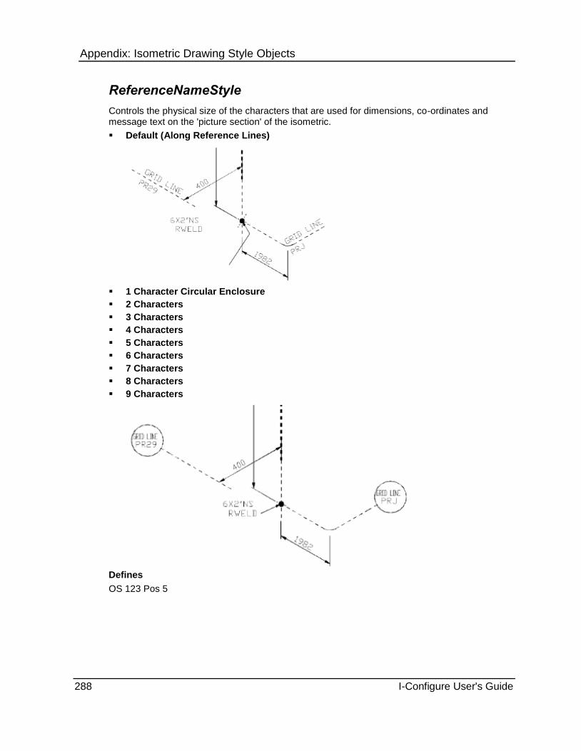
Appendix: Isometric Drawing Style Objects
288 I-Configure User's Guide
ReferenceNameStyle
Controls the physical size of the characters that are used for dimensions, co-ordinates and message text on the 'picture section' of the isometric.
Default (Along Reference Lines)
1 Character Circular Enclosure
2 Characters
3 Characters
4 Characters
5 Characters
6 Characters
7 Characters
8 Characters
9 Characters
Defines
OS 123 Pos 5

Appendix: Isometric Drawing Style Objects
I-Configure User's Guide 289
CurvedPipeAngleStyle
Controls the dimensioning of curved pipe.
Suppress - Suppress curved pipe angles.
With dimension - Output curved pipe angles as part of dimensions.
Defines
OS 84 Pos 2
CurvedPipeRadiusStyle
Controls the dimensioning of curved pipe.
Message - Output curved pipe radii as a message.
Suppress - Suppress curved pipe radii.
Defines
OS 84 Pos 3
Drawing.Layers Object Sets the default colour for the layer.
The Drawing.Layers object also folder contains a collection of options that are used to list the layers of the isometric drawing and the content for each layer. For more information, see Drawing.Layers Layers Collection (on page 289).
DefaultColour (on page 289)
Count (on page 289)
DefaultColour
Identifies an integer value that corresponds to a colour as defined in an output drawing system, such as MicroStation or AutoCAD. This colour is the default colour for all layers, if a colour is not set explicitly.
Count
Displays the number of layers defined in the current style and stored in the Drawing.Layers Layers collection (on page 289).
Drawing.Layers Layers Collection
Stores the definitions of the layer names and colours assigned to layer numbers.
The value that appears in parentheses after the collection name is a count of how many definitions are currently stored in the collection.
LayerColour (on page 290)
LayerNumber (on page 290)
Name (on page 290)

Appendix: Isometric Drawing Style Objects
290 I-Configure User's Guide
LayerColour
Specifies the optional colour integer number to override the default colour as defined in the output drawing system (MicroStation or AutoCAD).
LayerNumber
Specifies the integer number that corresponds to the layer used in the Drawing.Definitions Definitions collection (on page 201).
Name
Specifies the name for the layer with this LayerNumber (on page 290).
Drawing.DynamicFonts Object The Drawing.DynamicFonts object contains a collection of options called Fonts, which is used to store the parameters of the user-defined fonts that are available for output on the isometric drawing. For more information, see Drawing.DynamicFonts Fonts Collection (on page 290).
Count (on page 290)
Count
Displays the number of dynamic fonts defined in the current style and stored in the Drawing.DynamicFonts Fonts collection.
Drawing.DynamicFonts Fonts Collection
Controls the output of user-specified dynamic fonts on the isometric drawing.
The value that appears in parentheses after the collection name is a count of how many definitions are currently stored in the collection.
FontNumber (on page 291)
FontName (on page 291)
FontCorrectionFactor (on page 291)
FontStyleName (on page 291)
FontMicrostationNumber (on page 291)
FontMultibyteWidth (on page 291)

Appendix: Isometric Drawing Style Objects
I-Configure User's Guide 291
FontNumber
Specifies the ISOGEN font number. The value you enter must be 3 digits and cannot exist in the ISOGEN font information file (Fontstd.fif). The first 300 numbers are reserved exclusively for use in the .fif file. As such, the value you enter must be 301 or higher.
FontName
Specifies the name of the user-specified font. The TrueType font that you enter must already be installed on the computer. Type the name of the font exactly as it appears in the C:\Windows\Fonts folder.
To view a list of installed fonts, click Start > Control Panel > Fonts.
FontCorrectionFactor
Specifies the factor by which the width of characters are adjusted so that the font neither falls short of nor overlaps the boxes/gaps that are provided for the text on the drawing. The default setting is 1. Typically, this value is adjusted up or down by 1 or 2 after viewing the isometric drawing output.
FontStyleName
Specifies the AutoCAD text style name.
FontMicrostationNumber
Specifies the MicroStation-specific index number of the required font. This option is required only if you want to view the correct font on the screen.
FontMultibyteWidth
Specifies the factor by which the width of all multibyte characters are adjusted so that the font neither falls short of nor overlaps the boxes/gaps that are provided for the text on the drawing.. The default setting is 2. Typically, this value is adjusted up or down by 1 or 2 after viewing the isometric drawing output.
Drawing.EndConnections Object The Drawing.EndConnections object contains a collection called End Connections, which is used to store the definitions of end connection identifiers. For more information, see Drawing.EndConnections EndConnections Collection (on page 292).
Count (on page 291)
Count
Displays the number of end connections defined in the current style and stored in the Drawing.EndConnections EndConnections collection.
Appendix: Isometric Drawing Style Objects
292 I-Configure User's Guide
Drawing.EndConnections EndConnections Collection
Stores the definitions of the end connection identifiers.
The value that appears in parentheses after the collection name is a count of how many definitions are currently stored in the collection.
Accumulation (on page 292)
EnclErec (on page 292)
EnclFab (on page 293)
EnclOffsh (on page 294)
Enclosure (on page 294)
Format (on page 295)
Group (on page 295)
GroupErec (on page 295)
GroupFab (on page 295)
GroupOffsh (on page 296)
Origin (on page 296)
Prefix (on page 296)
PrefixErec (on page 296)
PrefixFab (on page 296)
PrefixOffsh (on page 296)
SKEY (on page 296)
Accumulation
Controls how end connection identifiers are sequenced.
Combined - Sequence end connection identifiers as combined. This is the default setting.
Category - Sequence end connection identifiers on a category basis.
This option is only relevant if Group is set to Individual.
See Also Group (on page 295)
EnclErec
Controls the type of enclosure that is used for Erection end connection identifiers output on the isometric drawing.
Circle - Display end connection identifiers inside a circular enclosure.
Circle Double - Display end connection identifiers inside a circular-shaped enclosure inside another circle.
Diamond Double - Display end connection identifiers inside a diamond-shaped enclosure inside another diamond-shaped enclosure.
Diamond Ended - Display end connection identifiers inside a diamond-ended box enclosure.
Diamond Ended Double - Display end connection identifiers inside a diamond-ended box enclosure inside another diamond-ended enclosure.
Ellipse - Display end connection identifiers inside an elliptical-shaped enclosure.
Ellipse Double - Display end connection identifiers inside an elliptical-shaped enclosure inside another ellipse.

Appendix: Isometric Drawing Style Objects
I-Configure User's Guide 293
Round Double - Display end connection identifiers inside a round-ended box enclosure inside another round-ended enclosure.
Round Ended - Display end connection identifiers inside a round-ended box enclosure.
Square Ended - Display end connection identifiers inside a square-ended box enclosure.
Square Ended Double - Display end connection identifiers inside a square-ended box enclosure inside another square-ended enclosure.
Suppressed - Suppress the display of an enclosure.
Triangle - Display end connection identifiers inside a triangular-shaped enclosure.
Triangle Double - Display end connection identifiers inside a triangular-shaped enclosure inside another triangle.
Unboxed - Display Erection end connection identifiers as unboxed.
EnclFab
Controls the type of enclosure that is used for Fabrication end connection identifiers output on the isometric drawing.
Circle - Display end connection identifiers inside a circular enclosure.
Circle Double - Display end connection identifiers inside a circular-shaped enclosure inside another circle.
Diamond Double - Display end connection identifiers inside a diamond-shaped enclosure inside another diamond-shaped enclosure.
Diamond Ended - Display end connection identifiers inside a diamond-ended box enclosure.
Diamond Ended Double - Display end connection identifiers inside a diamond-ended box enclosure inside another diamond-ended enclosure.
Ellipse - Display end connection identifiers inside an elliptical-shaped enclosure.
Ellipse Double - Display end connection identifiers inside an elliptical-shaped enclosure inside another ellipse.
Round Double - Display end connection identifiers inside a round-ended box enclosure inside another round-ended enclosure.
Round Ended - Display end connection identifiers inside a round-ended box enclosure.
Square Ended - Display end connection identifiers inside a square-ended box enclosure.
Square Ended Double - Display end connection identifiers inside a square-ended box enclosure inside another square-ended enclosure.
Suppressed - Suppress the display of an enclosure.
Triangle - Display end connection identifiers inside a triangular-shaped enclosure.
Triangle Double - Display end connection identifiers inside a triangular-shaped enclosure inside another triangle.
Unboxed - Display Fabrication end connection identifiers as unboxed.

Appendix: Isometric Drawing Style Objects
294 I-Configure User's Guide
EnclOffsh
Controls the type of enclosure that is used for Offshore end connection identifiers output on the isometric drawing.
Circle - Display end connection identifiers inside a circular enclosure.
Circle Double - Display end connection identifiers inside a circular-shaped enclosure inside another circle.
Diamond Double - Display end connection identifiers inside a diamond-shaped enclosure inside another diamond-shaped enclosure.
Diamond Ended - Display end connection identifiers inside a diamond-ended box enclosure.
Diamond Ended Double - Display end connection identifiers inside a diamond-ended box enclosure inside another diamond-ended enclosure.
Ellipse - Display end connection identifiers inside an elliptical-shaped enclosure.
Ellipse Double - Display end connection identifiers inside an elliptical-shaped enclosure inside another ellipse.
Round Double - Display end connection identifiers inside a round-ended box enclosure inside another round-ended enclosure.
Round Ended - Display end connection identifiers inside a round-ended box enclosure.
Square Ended - Display end connection identifiers inside a square-ended box enclosure.
Square Ended Double - Display end connection identifiers inside a square-ended box enclosure inside another square-ended enclosure.
Suppressed - Suppress the display of an enclosure.
Triangle - Display end connection identifiers inside a triangular-shaped enclosure.
Triangle Double - Display end connection identifiers inside a triangular-shaped enclosure inside another triangle.
Unboxed - Display Offshore end connection identifiers as unboxed.
Enclosure
Controls the type of enclosure that is used for end connection identifiers output on the isometric drawing.
Circle - Display end connection identifiers inside a circular enclosure.
Circle Double - Display end connection identifiers inside a circular-shaped enclosure inside another circle.
Diamond Double - Display end connection identifiers inside a diamond-shaped enclosure inside another diamond-shaped enclosure.
Diamond Ended - Display end connection identifiers inside a diamond-ended box enclosure.
Diamond Ended Double - Display end connection identifiers inside a diamond-ended box enclosure inside another diamond-ended enclosure.
Ellipse - Display end connection identifiers inside an elliptical-shaped enclosure.
Ellipse Double - Display end connection identifiers inside an elliptical-shaped enclosure inside another ellipse.
Round Double - Display end connection identifiers inside a round-ended box enclosure inside another round-ended enclosure.
Round Ended - Display end connection identifiers inside a round-ended box enclosure.
Square Ended - Display end connection identifiers inside a square-ended box enclosure.

Appendix: Isometric Drawing Style Objects
I-Configure User's Guide 295
Square Ended Double - Display end connection identifiers inside a square-ended box enclosure inside another square-ended enclosure.
Suppressed - Suppress the display of an enclosure.
Triangle - Display end connection identifiers inside a triangular-shaped enclosure.
Triangle Double - Display end connection identifiers inside a triangular-shaped enclosure inside another triangle.
Unboxed - Display end connection identifiers as unboxed.
Format
Controls the format of end connection identifiers that are output on the isometric drawing.
Numeric - Assign numeric values to end connection identifiers.
Alphabetic - Assign alphabetic characters to end connection identifiers.
This option is only relevant if Group is set to Individual.
See Also Group (on page 295)
Group
Controls which group of end connections are assigned identifiers on the isometric drawing.
Individual - Assign end connection identifiers to each individual occurrence of the specified end connection.
Assembly - Assign end connection identifiers to assemblies.
Weld - Assign end connection identifiers to welds.
GroupErec
Controls which group of Erection category end connections are assigned identifiers on the isometric drawing.
Individual - Assign end connection identifiers to each individual Erection occurrence of the specified end connection.
Assembly - Assign identifiers to Erection assemblies.
Weld - Assign identifiers to Erection welds.
GroupFab
Controls which group of Fabrication category end connections are assigned identifiers on the isometric drawing.
Individual - Assign end connection identifiers to each individual Fabrication occurrence of the specified end connection.
Assembly - Assign identifiers to Fabrication assemblies.
Weld - Assign identifiers to Fabrication welds.

Appendix: Isometric Drawing Style Objects
296 I-Configure User's Guide
GroupOffsh
Controls which group of Offshore category end connections are assigned identifiers on the isometric drawing.
Individual - Assign end connection identifiers to each individual Offshore occurrence of the specified end connection.
Assembly - Assign identifiers to Offshore assemblies.
Weld - Assign identifiers to Offshore welds.
Origin
Controls the origin of sequencing of end connection identifiers.
Pipeline - Sequence end connection identifiers on a per pipeline basis. This is the default setting.
Drawing - Sequence end connection identifiers on a per drawing basis.
This option is only relevant if Group is set to Individual.
See Also Group (on page 295)
Prefix
Controls the prefix used when outputting end connection identifiers on the isometric drawing.
PrefixErec
Controls the prefix used when outputting Erection category end connection identifiers output on the isometric drawing.
PrefixFab
Controls the prefix used when outputting Fabrication end connection identifiers output on the isometric drawing.
PrefixOffsh
Controls the prefix used when outputting Offshore end connection identifiers output on the isometric drawing.
SKEY
Identifies the end connection that is being defined. You can specify any of the following:
SW - Socket Weld
SC- Screwed
CP - Compression
FL- Flanged
PL - Plain End
BW - Butt Weld
CL - Clamped
GL - Glued

Appendix: Isometric Drawing Style Objects
I-Configure User's Guide 297
FA - Flared
PF - Push Fit
Drawing.Revisions Object Controls the output of revision changes on the isometric drawing. Revision output is triggered only when the component and pipeline revisions match. During isometric drawing generation, the software considers each component individually. When a revision match occurs, the component is highlighted on the isometric drawing.
The Drawing.Revisions object contains the properties listed below, any of which can be modified as needed.
Enabled (on page 297)
Distance (on page 297)
Colour (on page 297)
Layer (on page 298)
FillColour (on page 298)
EnclosureType (on page 298)
MinCloudArc (on page 299)
MaxCloudArc (on page 299)
Enabled
Controls the output of the Revision block to the Data Definition (DDF) file. When the component revision matches the pipeline revision, the revision output is triggered.
True - Output the revision block to the DDF file.
False - Suppress output of the revision block to the DDF file.
Distance
Controls the distance that highlighting displays from the component centerline.
Value - Type a value in 1/10th mms. The default setting is 50. The setting you define should not exceed the setting of a standard leg length, as this can create an unsatisfactory representation.
Colour
Controls the colour of the revision box.
Value - Type the index number that corresponds to the colour defined in drawing system. The default setting is the colour associated with the Layer attribute.
See Also Layer (on page 298)

Appendix: Isometric Drawing Style Objects
298 I-Configure User's Guide
Layer
Controls the layer of the revision box.
Value - Type the layer number. The default setting is 0.
FillColour
Controls the fill colour of the revision box.
Value - Type the index number that corresponds to the colour defined in the drawing system. The default setting is the colour associated with the Layer attribute.
See Also Layer (on page 298)
EnclosureType
Controls the output of the enclosure type that surrounds the revision block to the Data Definition (DDF) file
Polygon - Highlights revised components with a polygon. This is the default setting.
Cloud - Highlights revised components with a cloud.

Appendix: Isometric Drawing Style Objects
I-Configure User's Guide 299
MinCloudArc
Defines the minimum pitch of the cloud enclosure. This option is required only when you set EnclosureType to Cloud.
Value - Type a value in 10th mms. The default setting is 20.
MaxCloudArc
Defines the maximum pitch of the cloud enclosure. This option is required only when you set EnclosureType to Cloud.
Value - Type a value in 10th mms. The default setting is 60.
Drawing.Welds Object Sets options for the display of welds on the isometric drawing.
The Drawing.Welds object also contains a group of options called Weld Enclosures, which is used to store the definitions of special enclosures. There are several different formats for the enclosure, For more information, see Drawing.Welds WeldEnclosures Object (on page 323).
ShowWelds (on page 300)
ShowWeldNumbers (on page 300)
ImpliedWelds (on page 301)
GeneralPrefix (on page 301)
GeneralWeldStartNo (on page 301)
WeldNumbers (on page 301)
showFabWeldNos (on page 301)
ShowFabWeldPrefix (on page 302)
FabPrefix (on page 302)
FabWeldStartNo (on page 302)
MessageArrowHeads (on page 302)
FabWeldEnclosure (on page 303)
FabWeldEnclSize (on page 305)
ShowErectWeldNos (on page 305)
ShowErectWeldPrefix (on page 305)
OffshorePrefix (on page 309)
OffshoreWeldStartNo (on page 309)
OffshoreWeldEnclosure (on page 309)
OffshoreWeldEnclSize (on page 311)
ShowFabSupportWeldNos (on page 311)
ShowFabSupportWeldPrefix (on page 311)
FabSupportPrefix (on page 312)
FabSupportWeldStartNo (on page 312)
FabSupportWeldEnclosure (on page 312)
FabSuppWeldEnclSize (on page 314)
ShowErectSupportWeldNos (on page 314)
ShowErectSupportWeldPrefix (on page 315)
ErectSupportPrefix (on page 315)

Appendix: Isometric Drawing Style Objects
300 I-Configure User's Guide
ErectSupportWeldStartNo (on page 315)
ErectSupportWeldEnclosure (on page 315)
ErectSuppWeldEnclSize (on page 316)
ShowOffshoreSupportWeldNos (on page 317)
ShowOffshoreSupportWeldPrefix (on page 317)
OffshoreSupportPrefix (on page 317)
OffshoreSupportWeldStartNo (on page 317)
OffshoreSuppWeldEnclSize (on page 319)
SpoolMatchesPipe (on page 320)
SupportWeldNumbers (on page 320)
SupportWeldSeq (on page 320)
SupportWeldTypeNos (on page 321)
TypeSequenceNumbers (on page 321)
WeldNumberSequence (on page 321)
WeldNumberSize (on page 321)
WeldNumberLength (on page 322)
WeldNumberType (on page 322)
WeldTypeIdentifiers (on page 322)
SpecialStatusWeldIdentifiers (on page 323)
WeldDiameterCalculationMethod (on page 323)
ShowWelds
Turns on and off the display of welds and weld numbers on the isometric drawing.
True - Display welds and weld numbers on the isometric drawing.
False - Suppress the display of welds and weld numbers on the isometric drawing.
WeldTypes allows a separate control on the different categories of weld that can be output. For more information, see Weld Logic (on page 160).
Defines
OS 53 Pos 1
OS 54 Pos 1
ShowWeldNumbers
Turns on and off the display of weld numbers on the isometric drawing.
True - Turn on the display of weld numbers on the plotted isometric.
False - Turn off the display of weld numbers on the plotted isometric.
This is a general control. There is also a separate control for all other supported weld types. For more information, see Weld Logic (on page 160).
Defines
OS 53 Pos 1

Appendix: Isometric Drawing Style Objects
I-Configure User's Guide 301
ImpliedWelds
Controls the creation of implied welds, such as those welds that are not explicitly defined in the PCF or IDF.
True - Generate implied welds.
False - Suppress implied welds.
Defines
OS 54 Pos 8
GeneralPrefix
General weld prefix used when none of the separate weld prefixes are set.
GeneralWeldStartNo
Sets a general start weld number in the WDF.
WeldNumbers
Controls the generation of weld numbers for any welds that do not have weld numbers defined in the Piping Component File (PCF) or Intermediate Data File (IDF). This property interacts with WeldNumberSequence and SpoolMatchesPipe. If WeldNumbers is set to False, then this property takes precedence over the other two when setting the value.
True - Generate weld numbers.
False - Suppress weld numbers.
Defines
OS 53 Pos 8
See Also WeldNumberSequence (on page 321) SpoolMatchesPipe (on page 320)
ShowFabWeldNos
Displays the fabrication weld numbers on the isometric drawing.
True - Display fabrication weld numbers on the plotted isometric.
False - Suppress fabrication weld numbers on the plotted isometric.
Defines
OS 75 Pos 1

Appendix: Isometric Drawing Style Objects
302 I-Configure User's Guide
ShowFabWeldPrefix
True - Show fabrication weld prefixes on the plotted isometric.
False - Suppress fabrication weld prefixes on the plotted isometric.
Defines
OS 75 Pos 2
FabPrefix
Sets the prefix used for fabrication type welds. In the following illustration, the prefix is set to F.
FabWeldStartNo
Sets a start weld number for fabrication welds in the weld definition file (WDF).
MessageArrowHeads
Controls whether messages to welds (including weld numbers and attributes) have arrowheads attached to message leader lines.
On - Show arrowheads on message leader lines.

Appendix: Isometric Drawing Style Objects
I-Configure User's Guide 303
Off - Suppress arrowheads on message leader lines.
Defines
OS 54 Pos 9
FabWeldEnclosure
Sets the style of enclosure for fabrication welds.
Default Circle - Display a fixed-sized circle enclosure.
Diamond End - Display diamond-ended box enclosure.
Round End - Display a round-ended box enclosure.
Small Triangle - Display a small, triangular-shaped enclosure.
Small Diamond - Display a small, diamond-shaped enclosure.
Square - Display a square-ended box enclosure.

Appendix: Isometric Drawing Style Objects
304 I-Configure User's Guide
Dynamic Circle - Display a dynamically-sized circle enclosure.
Double Circle - Display a dynamically-sized double circle enclosure.
Ellipse - Displays an elliptical enclosure.
None - Suppress the display of a weld number enclosure.
All the previous illustrations use weld prefixes except for Default Circle, where weld prefixes cannot be used, as this is limited to numeric values (3 characters maximum).
The size at which the circle, double circle and ellipse are drawn is controlled by FabWeldEnclSize (default 2 characters), which defines the minimum size for the enclosure. If there are more characters than the value that is set, the enclosure dynamically adjusts to suit.
When the weld number enclosure style is not the original circular type, then the weld number character size is controlled by TextSize and not WeldNumberSize .
Defines
OS 75 Pos 1, 7
See Also FabWeldEnclSize (on page 305) WeldNumberSize (on page 321) TextSize (on page 286)

Appendix: Isometric Drawing Style Objects
I-Configure User's Guide 305
FabWeldEnclSize
Controls the number of characters used for the size of circle, double circle and ellipse enclosure style. The default setting is 2, and the valid entries are from 1 to 8 characters or Variable size, which dynamically sizes the enclosure.
The number of characters defines the minimum size at which the circle, double circle and ellipse enclosures are drawn. If there are more characters than the value that is set, the enclosure dynamically adjusts to suit. Setting FabWeldEnclSize to Variable size allows the circle, double circle and ellipse to be smaller than the default of 2 characters, but again all will dynamically adjust to suit the number of characters.
Defines
OS 54 Pos 2
ShowErectWeldNos
Displays the erection weld numbers on the isometric drawing.
True - Display erection weld numbers on the plotted isometric.
False - Suppress erection weld numbers on the plotted isometric.
Defines
OS 75 Pos 3
ShowErectWeldPrefix
True - Show erection weld prefixes on the plotted isometric.
False - Suppress erection weld prefixes on the plotted isometric.
Defines
OS 75 Pos 4

Appendix: Isometric Drawing Style Objects
306 I-Configure User's Guide
ErectPrefix
Sets the prefix used for erection type welds.
In the following illustration, the prefix is set to E.
ErectWeldStartNo
Sets a start weld number for erection welds in the weld definition file (WDF).
ErectWeldEnclosure
Sets the style of enclosure for erection welds.
All of the following illustration use weld prefixes, except for the default circle where weld prefixes cannot be used, as this is limited to numeric values, 3 characters maximum.
Default Circle - Display a fixed-sized circle enclosure.

Appendix: Isometric Drawing Style Objects
I-Configure User's Guide 307
Diamond End - Display a diamond-ended enclosure.
Round End - Display a round-ended enclosure.
Small Triangle - Display a small triangular-shaped enclosure.
Small Diamond - Display a small diamond-shaped enclosure.
Square - Display a square-ended box.
Dynamic Circle - Displays a dynamically-sized circle.

Appendix: Isometric Drawing Style Objects
308 I-Configure User's Guide
Double Circle - Display a dynamically-sized double circle enclosure.
Ellipse - Display an elliptical enclosure.
None - Suppress the display of a weld number enclosure.
The size at which the Circle, Double Circle and Ellipse are drawn is controlled by ErecWeldEnclSize (default 2 characters), which defines the minimum size for the enclosure. If there are more characters than the value set, the enclosure dynamically adjusts to suit.
When the weld number enclosure style is not the original circular type, then the weld number character size is controlled by TextSize and not by WeldNumberSize .
Defines
OS 75 Pos 3, 8
See Also ErectWeldEnclSize (on page 308) TextSize (on page 286) WeldNumberSize (on page 321)
ErectWeldEnclSize
Controls the number of characters used for the size of circle, double circle and ellipse enclosure style. The default setting is 2, and the valid entries are from 1 to 8 characters and Variable size, which dynamically sizes the enclosure.
The number of characters defines the minimum size at which the circle, double, circle, and ellipse are drawn. If there are more characters than the value that is set, the enclosure dynamically adjusts to suit. Setting ErecWeldEnclSize to Variable size allows the circle, double

Appendix: Isometric Drawing Style Objects
I-Configure User's Guide 309
circle and ellipse to be smaller than the default 2 characters, while also allowing the enclosure to dynamically adjust to suit the number of characters.
Defines
OS 54 Pos 3
ShowOffshoreWeldNos
Displays the offshore weld numbers on the isometric drawing.
True - Display offshore weld numbers on the plotted isometric.
False - Suppress offshore weld numbers on the plotted isometric.
Defines
OS 75 Pos 5
ShowOffshoreWeldPrefix
True - Shows offshore weld prefixes on the plotted isometric.
False - Suppresses offshore support weld prefixes on the plotted isometric.
OffshorePrefix
Sets the prefix used for offshore type welds.
In the following illustration, the prefix is set to O.
OffshoreWeldStartNo
Sets a start weld number for offshore welds in the weld definition file (WDF).
OffshoreWeldEnclosure
Sets the style of enclosure for offshore welds.
Default Circle - Display a fixed-sized circle enclosure.

Appendix: Isometric Drawing Style Objects
310 I-Configure User's Guide
Diamond End - Display a diamond-ended box enclosure.
Round End - Display a round-ended box enclosure.
Small Triangle - Display a small, triangular-shaped enclosure.
Small Diamond - Display a small, diamond-shaped enclosure.
Square - Display a square-ended box enclosure.
Dynamic Circle - Display a dynamically-sized circle enclosure.
Double Circle - Display a dynamically-sized double circle enclosure.
Ellipse - Display an elliptical enclosure.

Appendix: Isometric Drawing Style Objects
I-Configure User's Guide 311
None - Suppress the display of a weld number enclosure.
Defines
OS 75 Pos 5
OffshoreWeldEnclSize
Controls the number of characters used for the size of circle, double circle and ellipse enclosure style. The default setting is 2, and the valid entries are from 1 to 8 characters or Variable size, which dynamically sizes the enclosure.
The number of characters defines the minimum size at which the circle, double, circle, and ellipse are drawn. If there are more characters than the value that is set, the enclosure dynamically adjusts to suit. Setting OffshoreWeldEnclSize to Variable size allows the circle, double circle and ellipse to be smaller than the default 2 characters, while also allowing the enclosure to dynamically adjust to suit the number of characters.
Defines
OS 54 Pos 4
ShowFabSupportWeldNos
Displays weld numbers for the specified weld type.
True - Display fabrication support weld numbers on the plotted isometric.
False - Suppress fabrication support weld numbers on the plotted isometric.
Defines
OS 78 Pos 1
ShowFabSupportWeldPrefix
True - Show fabrication support weld prefixes on the plotted isometric.
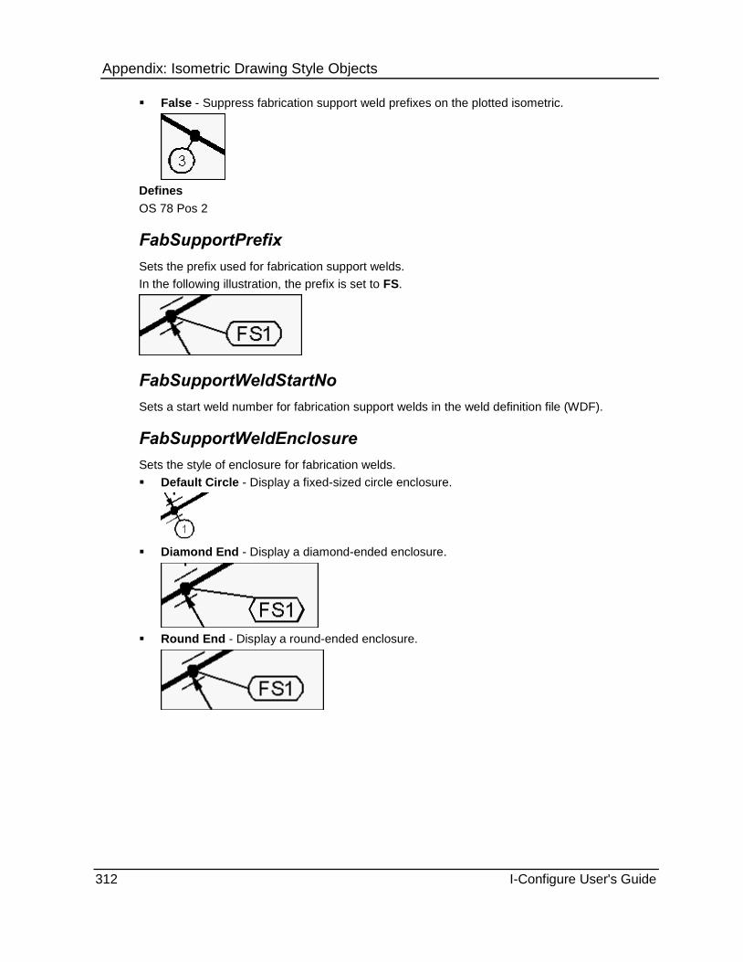
Appendix: Isometric Drawing Style Objects
312 I-Configure User's Guide
False - Suppress fabrication support weld prefixes on the plotted isometric.
Defines
OS 78 Pos 2
FabSupportPrefix
Sets the prefix used for fabrication support welds.
In the following illustration, the prefix is set to FS.
FabSupportWeldStartNo
Sets a start weld number for fabrication support welds in the weld definition file (WDF).
FabSupportWeldEnclosure
Sets the style of enclosure for fabrication welds.
Default Circle - Display a fixed-sized circle enclosure.
Diamond End - Display a diamond-ended enclosure.
Round End - Display a round-ended enclosure.

Appendix: Isometric Drawing Style Objects
I-Configure User's Guide 313
Small Triangle - Display a small, triangular-shaped enclosure.
Small Diamond - Display a small, diamond-shaped enclosure.
Square - Display a square-ended enclosure.
Dynamic Circle - Display a dynamically-sized circle enclosure.
Double Circle - Display a dynamically-size double circle enclosure.
Ellipse - Display an elliptical enclosure.

Appendix: Isometric Drawing Style Objects
314 I-Configure User's Guide
None - Suppress the display of a weld number enclosure.
All the previous illustrations use weld prefixes except for Default Circle, where weld prefixes cannot be used, as this is limited to numeric values (3 characters maximum).
The size at which the circle, double circle and ellipse are drawn is controlled by FabSuppWeldEnclSize (default 2 characters), which defines the minimum size for the enclosure. If there are more characters than the value that is set, the enclosure dynamically adjusts to suit.
When the weld number enclosure style is not the original circular type, then the weld number character size is controlled by TextSize and not WeldNumberSize.
Defines
OS 78 Pos 1, 7
See Also WeldNumberSize (on page 321) TextSize (on page 286)
FabSuppWeldEnclSize
Controls the number of characters used for the size of circle, double circle and ellipse enclosure style. The default setting is 2, and the valid entries are from 1 to 8 characters or Variable size, which dynamically sizes the enclosure.
The number of characters defines the minimum size that at which the circle, double, circle, and ellipse are drawn. If there are more characters than the value that is set, the enclosure dynamically adjusts to suit. Setting FabSuppWeldEnclSize to Variable size allows the circle, double circle and ellipse to be smaller than the default 2 characters, while also allowing the enclosure to dynamically adjust to suit the number of characters.
Defines
OS 54 Pos 5
ShowErectSupportWeldNos
Displays weld numbers for the specified weld type.
True - Display erection support weld numbers on the plotted isometric.
False - Suppress erection support weld numbers on the plotted isometric.
Defines
OS 78 Pos 3

Appendix: Isometric Drawing Style Objects
I-Configure User's Guide 315
ShowErectSupportWeldPrefix
True - Show erection support weld prefixes on the plotted isometric.
False - Suppress erection support weld prefixes on the plotted isometric.
Defines
OS 78 Pos 4
ErectSupportPrefix
Sets the prefix used for erection support welds.
In the following illustration, the prefix is set to ES.
ErectSupportWeldStartNo
Sets a start weld number for erection support welds in the weld definition file (WDF).
ErectSupportWeldEnclosure
Specifies the style of the weld number enclosure for this weld type.
Default Circle - Display a fixed-sized circle enclosure.
Diamond End - Display a diamond-ended box enclosure.
Round End - Display a round-ended box enclosure.
Small Triangle - Display a small, triangular-shaped enclosure.
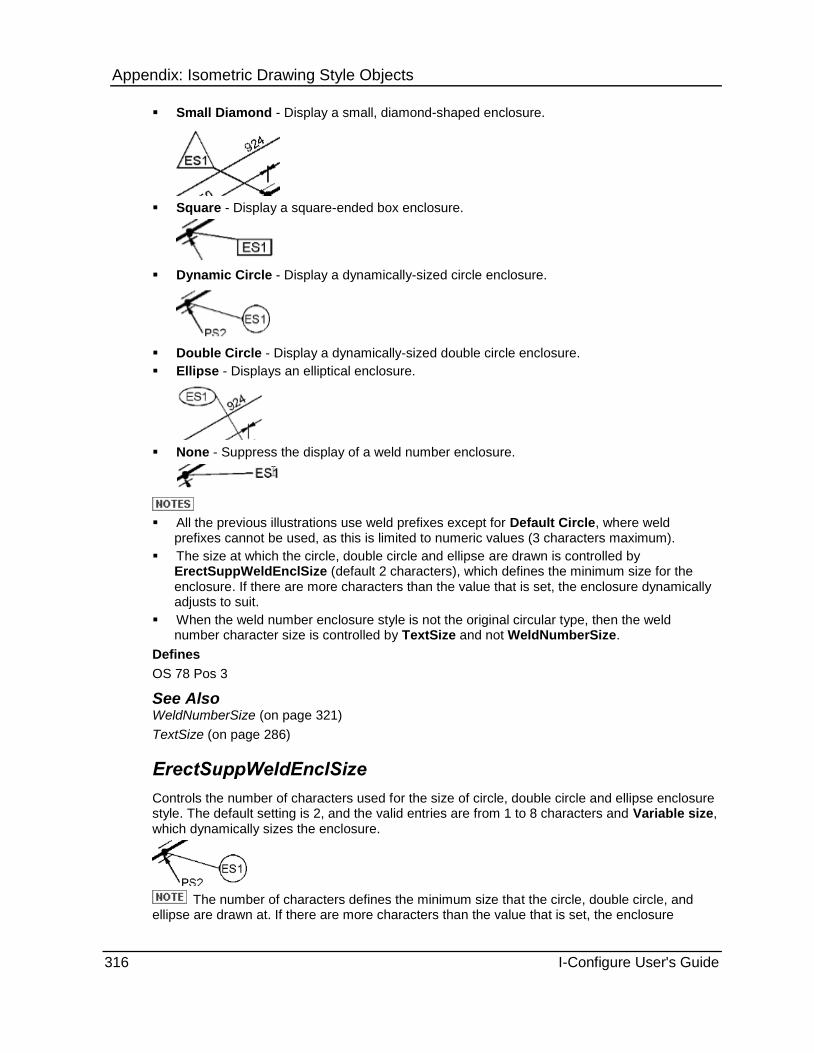
Appendix: Isometric Drawing Style Objects
316 I-Configure User's Guide
Small Diamond - Display a small, diamond-shaped enclosure.
Square - Display a square-ended box enclosure.
Dynamic Circle - Display a dynamically-sized circle enclosure.
Double Circle - Display a dynamically-sized double circle enclosure.
Ellipse - Displays an elliptical enclosure.
None - Suppress the display of a weld number enclosure.
All the previous illustrations use weld prefixes except for Default Circle, where weld prefixes cannot be used, as this is limited to numeric values (3 characters maximum).
The size at which the circle, double circle and ellipse are drawn is controlled by ErectSuppWeldEnclSize (default 2 characters), which defines the minimum size for the enclosure. If there are more characters than the value that is set, the enclosure dynamically adjusts to suit.
When the weld number enclosure style is not the original circular type, then the weld number character size is controlled by TextSize and not WeldNumberSize.
Defines
OS 78 Pos 3
See Also WeldNumberSize (on page 321)
TextSize (on page 286)
ErectSuppWeldEnclSize
Controls the number of characters used for the size of circle, double circle and ellipse enclosure style. The default setting is 2, and the valid entries are from 1 to 8 characters and Variable size, which dynamically sizes the enclosure.
The number of characters defines the minimum size that the circle, double circle, and ellipse are drawn at. If there are more characters than the value that is set, the enclosure
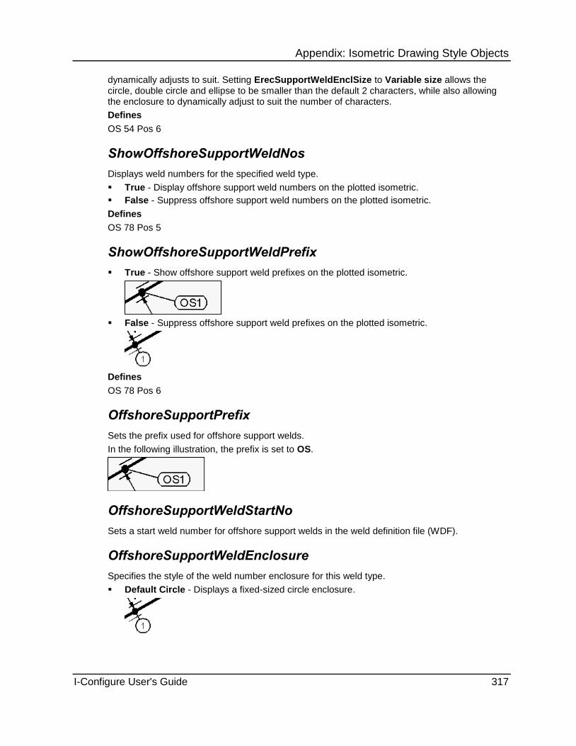
Appendix: Isometric Drawing Style Objects
I-Configure User's Guide 317
dynamically adjusts to suit. Setting ErecSupportWeldEnclSize to Variable size allows the circle, double circle and ellipse to be smaller than the default 2 characters, while also allowing the enclosure to dynamically adjust to suit the number of characters.
Defines
OS 54 Pos 6
ShowOffshoreSupportWeldNos
Displays weld numbers for the specified weld type.
True - Display offshore support weld numbers on the plotted isometric.
False - Suppress offshore support weld numbers on the plotted isometric.
Defines
OS 78 Pos 5
ShowOffshoreSupportWeldPrefix
True - Show offshore support weld prefixes on the plotted isometric.
False - Suppress offshore support weld prefixes on the plotted isometric.
Defines
OS 78 Pos 6
OffshoreSupportPrefix
Sets the prefix used for offshore support welds.
In the following illustration, the prefix is set to OS.
OffshoreSupportWeldStartNo
Sets a start weld number for offshore support welds in the weld definition file (WDF).
OffshoreSupportWeldEnclosure
Specifies the style of the weld number enclosure for this weld type.
Default Circle - Displays a fixed-sized circle enclosure.

Appendix: Isometric Drawing Style Objects
318 I-Configure User's Guide
Diamond End - Display a diamond-ended box enclosure.
Round End - Display a round-ended box enclosure.
Small Triangle - Display a small, triangular-shaped enclosure.
Small Diamond - Display a small, diamond-shaped enclosure.
Square - Display a square-ended box enclosure.
Dynamic Circle - Display a dynamically-sized circle enclosure.

Appendix: Isometric Drawing Style Objects
I-Configure User's Guide 319
Double Circle - Display a dynamically-sized double circle enclosure.
Ellipse - Display an elliptical enclosure.
None - Suppress the display of a weld number enclosure.
Defines
OS 78 Pos 5
OffshoreSuppWeldEnclSize
Controls the number of characters used for the size of circle, double circle and ellipse enclosure style. The default setting is 2, and the valid entries are from 1 to 8 characters or Variable size, which dynamically sizes the enclosure.
The number of characters defines the minimum size at which the circle, double, circle, and ellipse are drawn. If there are more characters than the value that is set, the enclosure dynamically adjusts to suit. Setting OffshoreSuppWeldEnclSize to Variable size allows the circle, double circle and ellipse to be smaller than the default 2 characters, while also allowing the enclosure to dynamically adjust to suit the number of characters.
Defines
OS 54 Pos 7

Appendix: Isometric Drawing Style Objects
320 I-Configure User's Guide
SpecialSiteWeldCategory
Assigns special site welds to a specific category. You can select Erection Type or Fabrication Type.
Defines
OS 83 Pos 3
SpoolMatchesPipe
Controls whether the weld numbers on the spool isometric match those on the full isometric.
True - Spool isometric weld numbers to match full isometric weld numbers.
False - Spool isometric Weld numbers done separately.
For spool weld numbers to match the full isometric numbers, the properties that affect the number of welds and the sequence used must be the same for both spool and full styles.
Defines
OS 53 Pos 3
See Also WeldNumbers (on page 301)
SupportWeldNumbers
Numbers support welds separately. The default is False.
True - Number support welds separately.
False - Number support welds using the same sequence as standard welds.
If set to True, then SupportWeldTypeNos is used to determine whether each category of weld has its own sequence or not.
Defines
OS 53 Pos 6
See Also SupportWeldTypeNos (on page 321)
SupportWeldSeq
Controls whether the support weld numbers continue across drawings, or start again on each new drawing.
Per Drawing - Re-start support weld numbering sequence on each drawing.
Continuous - Continue support weld numbering sequence across drawings.
The numbers used depend on the settings defined by SupportWeldTypeNos.
If you set SupportWeldNumbers to True, SupportWeldSeq controls weld numbering, similar to WeldNumberSequence.
Defines
OS 53 Pos 7
See Also SupportWeldTypeNos (on page 321)

Appendix: Isometric Drawing Style Objects
I-Configure User's Guide 321
SupportWeldTypeNos
Controls the numbering of support welds. The default is False.
True - The software numbers each type of support weld in a different sequence.
False - The software numbers each type of support weld using the same sequence for numbers.
Defines
OS 53 Pos 6
TypeSequenceNumbers
Controls whether there is an individual sequence for weld numbers based on their category (Fabrication, Erection or Offshore) or just one sequence for all welds.
True - Each type of Weld has its own sequence numbers.
False - Single sequence for all Welds.
If set to True, then the SupportWeldNumbers and SupportWeldTypeNos properties allow additional control for support weld numbering.
Defines
OS 53 Pos 5
See Also SupportWeldNumbers (on page 320) SupportWeldTypeNos (on page 321)
WeldNumberSequence
Continuous - For weld number current sequence to continue on each new drawing.
Per drawing - For weld number sequence to restart on each new drawing.
Defines
OS 53 Pos 3
See Also WeldNumbers (on page 301)
WeldNumberSize
Controls the size of plotted weld numbers, if welds appear.
Small - Plot small weld numbers (1.5 mm).
Medium - Plot medium-sized weld numbers (1.8 mm).
Large - Plot large weld numbers (2.1 mm).
These size values are only valid for the original circular style enclosure. If one of the alternative enclosure styles is being used, then TextSize is used.
Defines
OS 53 Pos 1
See Also TextSize (on page 286)

Appendix: Isometric Drawing Style Objects
322 I-Configure User's Guide
WeldNumberLength
Controls the number of characters output for a weld number. For numeric weld numbers, leading zeros are output; for alphabetic weld numbers, spaces are output
Variable - Output the weld number without leading zeros or spaces.
1 to 9 - Set the number of characters to be output. For example, 3 outputs 001 through to 999 for numeric weld numbers.
Defines
OS 53 Pos 9
WeldNumberType
Controls whether weld numbers are numeric or alphabetic.
Numeric - Numeric weld identifiers.
Alphabetic - Alphabetic weld identifiers. Generates A to Z, and then starts AA, AB, AC, and so on.
Defines
OS 53 Pos 8
WeldTypes
Controls whether all welds are numbered/plotted or allows single weld category (Fabrication, Erection or Offshore) to be numbered/plotted.
All - Number/plot all welds.
Fabrication Only - Number/plot only fabrication welds.
Erection Only - Number/plot only erection welds.
Offshore Only - Number/plot only offshore welds.
If Offshore Only is set, then erection welds are plotted but not numbered. This is a general control, but there is also a separate control for all six weld types. If the separate weld types are set not to be plotted, then this control still causes a weld number to be generated for those welds so that they can be used on weld reports.
Defines
OS 53 Pos 1, 4
OS 54 Pos 1

Appendix: Isometric Drawing Style Objects
I-Configure User's Guide 323
WeldTypeIdentifiers
Defines the text to be output to the weld definition file (WDF) for weld type identifiers. Double-click the WeldTypeIdentifiers box. The software opens the WeldTypeIdentifiers text editor, in which you can input the required data as follows:
26. Piping Specification
27. Minimum Nominal size
28. Maximum Nominal size
29. Weld Type (replacement for BW welds)
30. Wall Thickness / Schedule (optional)
The WELD-TYPE-IDENTIFIER heading is output by I-Configure, and only the data records are required in the text file.
CS-150 0.5 1.5 B2 80
CS-150 2 6 B3 40
CS-150 8 12 B8 30
The nominal size units are assumed to be those specified by Drawing.Controls.Units (OS 41). This is only used when the weld type is output on the weld operation list or welds report, and replaces the BW weld type identifier. If using the Wall Thickness / Schedule column, and the BW type is not being changed, then BW must be entered on the line.
See Also Units (on page 198)
SpecialStatusWeldIdentifiers
Controls the generation of weld numbers on special status welds.
True - Generate weld numbers on special status welds.
False - Suppress generation of weld numbers on special status welds.
Defines
OS 83 Pos 2
WeldDiameterCalculationMethod
Defines the method used by ISOGEN to calculate weld diameter totals.
Using Cost Factor - Calculate weld diameter totals using specified cost factors.
Using Nominal Size - Calculate weld diameter totals using nominal sizes
Defines
OS 83 Pos 4
Drawing.Welds WeldEnclosures Object
The Drawing.Welds WeldEnclosures object contains a collection called WeldEnclosures, which is used to store the definitions of special enclosures. There are several different formats for the enclosure, which are controlled by the settings of the EnclosureType property. For more information, see Drawing.Welds WeldEnclosures Collection (on page 324).
Count (on page 324)

Appendix: Isometric Drawing Style Objects
324 I-Configure User's Guide
Count
Displays the number of WeldEnclosures currently defined in the style.
Drawing.Welds WeldEnclosures Collection
Defines special types of enclosure used for welds in order to display attributes set on the weld in the PCF/IDF.
The special weld enclosure supersedes weld enclosure styles set as a property of the Drawing.Welds object for each category of weld or all welds, depending on the Category setting on the WeldEnclosure collection.
AttributeName (on page 324)
Category (on page 324)
EnclosureType (on page 324)
ForceAllWeldsAsSpecial (on page 325)
NonSpecialPosition (on page 326)
SpecialPosition (on page 326)
Width (on page 327)
AttributeName
Specifies the name of the attribute being defined. Use the AttributeName list to select the required attribute.
Category
Specifies the category. Use the Category list to select the appropriate one: Fabrication, Erection, Offshore or All.
EnclosureType
Controls the type of enclosure to be used.
Pointed
Round
Triangle
Diamond
Square

Appendix: Isometric Drawing Style Objects
I-Configure User's Guide 325
Circle
Unboxed
SpecialPointed
SpecialRound
SpecialSquare
ForceAllWeldsAsSpecial
Only applies to objects with EnclosureType set to SpecialPointed, SpecialRound, or SpecialSquare and AttributeName mapped to WELD-NO.
True - Force all welds to adopt the special layout for their enclosure.
False - Allow the generation of an enclosure containing only the weld number, when the data for all the other fields in an enclosure are missing.
See Also AttributeName (on page 332) EnclosureType (on page 324)

Appendix: Isometric Drawing Style Objects
326 I-Configure User's Guide
NonSpecialPosition
Defines the position for the specified weld attribute to be output along the horizontal display. Type the position number.
Applies only to the following enclosure types, all of which allow multiple attributes displayed horizontally:
Pointed
Round
Square
SpecialPosition
Controls selection of the compartment or quadrant (position) for the weld number when weld attributes are to be output in a special enclosure. Select the position from the following list of choices: Top, TopLeft, TopRight, Bottom, BottomLeft, and BottomRight.
In the following example, the weld number is output TopRight, where 1 denotes the weld number and there are three weld attributes (T2, R2 and F8).
You can divide special enclosures into two compartments (top and bottom) or four compartments (quadrants).
The maximum number of compartments is four.
This attribute only applies to SpecialPointed, SpecialRound, or SpecialSquare enclosure types.
The previous example is SpecialRound.
See Also Weld Attributes (on page 106) NonSpecialPosition (on page 326)

Appendix: Isometric Drawing Style Objects
I-Configure User's Guide 327
Width
Specifies the number of characters.
DrawingFrame Object Sets options for the drawing frame on the isometric drawing.
BottomMargin (on page 327)
TopMargin (on page 328)
LeftMargin (on page 328)
RightMargin (on page 328)
CustomHeight (on page 329)
CustomWidth (on page 329)
DXFUnits (on page 329)
ReservedAreaDrawing (on page 329)
ReservedAreaDrawingTop (on page 330)
ReservedAreaMatList (on page 330)
TemplateFile (on page 330)
TemplateFormat (on page 330)
Visible (on page 331)
The DrawingFrame object also contains the following groups of options:
Attributes - Maps ISOGEN attributes to attributes in the software and specifies the X- and Y-coordinates of the attribute placement. For more information, see DrawingFrame.Attributes Object (on page 331).
Table Attributes - Stores the definitions of text used on the drawing frame. For more information, see DrawingFrame.TableAttributes Object (on page 338).
Symbol Table - Defines the properties for symbol shape frame positioning. For more information, see DrawingFrame.SymbolTable Object (on page 341).
The existing Supplementary.TableAttributes object (on page 484) contains the same information as the DrawingFrame.TableAttributes object. You can use either object to modify the properties, although the DrawingFrame.TableAttributes object supports real numbers in the XPos and YPos properties.
BottomMargin Specifies the distance between the outer edge of the drawing sheet and the outer line of the drawing frame at the bottom of the drawing.
0 - Use the default for no reserved area.
Value - User-defined distance between the outer edge of the drawing sheet and the outer line of the drawing frame that is being used. Type a value (real number) in mm or inches, depending on the setting of the drawing units on the Options dialog box.
Defines
OS 13
See Also Options (on page 36)

Appendix: Isometric Drawing Style Objects
328 I-Configure User's Guide
TopMargin Specifies the distance between the outer edge of the drawing sheet and the outer line of the drawing frame at the top of the drawing.
0 - Use the default for no reserved area.
Value (real number) - User-defined distance between the outer edge of the drawing sheet and the outer line of the drawing frame that is being used. Type a value in mm or inches, depending on the setting of the drawing units on the Options dialog box.
Defines
OS 12
See Also Options (on page 36)
LeftMargin Specifies the distance between the outer edge of the drawing sheet and the outer line of the drawing frame on the left side of the drawing.
0 - Use the default for no reserved area.
Value - User-defined distance between the outer edge of the drawing sheet and the outer line of the drawing frame that is being used. Type a value (real number) in mm or inches, depending on the setting of the drawing units on the Options dialog box.
Defines
OS 10
See Also
Options (on page 36)
RightMargin Specifies the distance between the outer edge of the drawing sheet and the outer line of the drawing frame on the right side of the drawing.
0 - Use the default for no reserved area.
Value - User-defined distance between the outer edge of the drawing sheet and the outer line of the drawing frame that is being used. Type a value (real number) in mm or inches, depending on the setting of the drawing units on the Options dialog box.
Defines
OS 11
See Also
Options (on page 36)

Appendix: Isometric Drawing Style Objects
I-Configure User's Guide 329
CustomHeight Sets the height of a non-standard paper size. That is, sizes that do not conform to either the metric-based European A series or the imperial-based American ANSI sizes.
0 - Use a non-standard drawing height.
Value - User-defined overall drawing height. Type a value (real number) in mm or inches, depending on the setting of the drawing units on the Options dialog box.
Defines
OS 15
See Also Options (on page 36)
CustomWidth Sets the width of a non-standard paper size. That is, sizes that do not conform to either the metric-based European A series or the imperial-based American ANSI sizes.
0 - Use a non-standard drawing width.
Value - User-defined overall drawing width. . Type a value (real number) in mm or inches, depending on the setting of the drawing units on the Options dialog box.
Defines
OS 16
See Also Options (on page 36)
DXFUnits mm - Specifies metric units.
Inch - Specifies imperial units.
Defines
OS 92
ReservedAreaDrawing Provides the distance between the bottom of the drawing area and the outer line of the drawing frame.
0 - Use the default for no reserved area.
Value (real number) - User-defined value equal to the depth of the required reserved area along the bottom of the isometric, measured from the outer line of the drawing frame. Type a value (real number) in mm or inches, depending on the setting of the drawing units on the Options dialog box.
Defines
OS 35 Pos 1, 2, 3
See Also Options (on page 36)

Appendix: Isometric Drawing Style Objects
330 I-Configure User's Guide
ReservedAreaDrawingTop Defines the reserved area along the top of the isometric.
0 - Use the default for no reserved area.
Value (real number) - User-defined value equal to the depth of the required reserved area along the bottom of the isometric, measured from the outer line of the drawing frame. Type a value (real number) in mm or inches, depending on the setting of the drawing units on the Options dialog box.
Defines
OS 35 Pos 7, 8 and 9
See Also Options (on page 36)
ReservedAreaMatList Provides the distance between the bottom of the material list and the outer line of the drawing frame.
Blank - Use the default for no reserved area.
Value (real number) - User-defined value equal to the depth of the required reserved area along the bottom of the material list measured from the outer line of the drawing frame. Type a value in mm or inches, depending on the setting of the drawing units on the Options dialog box.
Defines
OS 35 Pos 4, 5, 6
See Also Options (on page 36)
TemplateFile Specifies the file used for the backing sheet.
31. Double-click in the TemplateFile box.
32. In the Browse for file dialog box, navigate to the required file and then click OK.
TemplateFormat Select the drawing format for the backing sheet.

Appendix: Isometric Drawing Style Objects
I-Configure User's Guide 331
Visible Controls plotting of the standard ISOGEN drawing frame.
It is likely that if you either plot your own design of backing frame or plot to frames on pre-printed forms, you will want to suppress the plotting of the standard ISOGEN drawing frame.
True - Plots the standard ISOGEN drawing frame.
False - Does not plot the standard ISOGEN drawing frame.
Defines
OS 18
DrawingFrame.Attributes Object The DrawingFrame.Attributes object contains a collection called DFAttributes, which is used to store the definitions of text used on the drawing frame. For more information, see DrawingFrame.Attributes DFAttributes Collection (on page 331)
Count (on page 331)
Count
Displays the number of attributes to be plotted in the drawing frame.
DrawingFrame.Attributes DFAttributes Collection
Specifies the attributes to plot on the drawing frame. Specifies attributes to plot in the drawing frame. You use these options with the Attribute Map and other Drawing Frame options.
Many of the attributes for the drawing frame originate from the pipe runs in the model. During an extraction, the software obtains the values for pipe run attributes from the run with the largest NPD.
The value that displays in parentheses after the collection name is a count of how many definitions are stored in the collection.
AttributeName (on page 332)
CharHeight (on page 335)
Xpos (on page 336)
Ypos (on page 336)
Font (on page 336)
BarCode (on page 336)
CharWidth (on page 336)
Justification (on page 336)
Layer (on page 336)
Colour (on page 337)
RotationAngle (on page 337)
TextWeight (on page 337)
TruncationLength (on page 337)
ColumnsNumber (on page 337)
Direction (on page 337)
LinesNumber (on page 337)
Xspacing (on page 337)

Appendix: Isometric Drawing Style Objects
332 I-Configure User's Guide
Yspacing (on page 337)
See Also Add an Item to a Collection (on page 171) Remove an Item from a Collection (on page 172)
AttributeName
Specifies the name of the attribute being defined. Double-click the AttributeName list to select the required attribute.
The -700 records listed below can be output using TextPos:
Equipment
-742 Equipment name
-743 Nozzle name
-744 Nozzle identifier
-745 Pipeline reference
-746 Nozzle size
-747 Nozzle world coordinates
-748 Nozzle relative coordinates
Flat Spools
-708 Flange part number
-709 Flange rotation angle
Location Points
-732 Location point to nearest steelwork staunchion
-733 Location point above nearest floor level
-749 Location point index number
-750 Location point (forward and aft)
-751 Location point (transverse)
-752 Location point (elevation)
-758 Volume name (reference plane sub-volume)

Appendix: Isometric Drawing Style Objects
I-Configure User's Guide 333
Miscellaneous
-700 North arrow X-Y position on drawing
-702 Drawing (sheet) number
-703 Number of drawings (sheets)
-741 Fitting shapes/symbols and associated description
Pipeline Information
-730 Pipeline erection factor
-734 Pipeline nominal sizes
-735 Pipeline centreline lengths
-736 Pipeline insulation lengths
-737 Pipeline heat tracing lengths
-738 Pipeline surface area (per pipeline)
-739 Pipeline surface area (per drawing)
-772 Pipeline start point coordinates
Spool Information
-728 Spool centreline length
-729 Spool erection factor
-740 Spool surface area (spools on current drawing)
-762 Spool number (without prefix)
-763 Number of spools on pipeline
-768 Spool weld diameter inches (spools on current drawing)
-769 Spool centreline lengths (spools on current drawing)
-770 Spool erection factor (spools on current drawing)
-771 Number of spools on drawing
-772 Spool start point coordinates
-773 Spool identifier (all spools in pipeline)

Appendix: Isometric Drawing Style Objects
334 I-Configure User's Guide
System Information
-755 System data
-756 System time
-757 User name
Weights
-704 Total weight for drawing
-705 Total Fabrication weight
-706 Total Erection weight
-707 Total Offshore weight
-710 Total weight unlisted items
-711 Total weight of pipeline
-712 Total wet (full) weight of pipeline
-713 Total insulation weight for pipeline
-714 CoG position of dry (empty) pipeline
-715 CoG position of dry pipeline + insulation
-716 CoG position of wet (full) pipeline
-717 CoG position of wet pipeline + insulation
-718 Total pipeline Fabrication weight
-719 Total pipeline Erection weight
-720 Total pipeline Offshore weight
-725 Spool weight
-726 Spool CoG position

Appendix: Isometric Drawing Style Objects
I-Configure User's Guide 335
Weld Diameters
-727 Weld diameters (per drawing)
-731 Weld diameters (per pipeline)
-759 Weld diameters - Fabrication (per pipeline)
-760 Weld diameters - Erection (per pipeline)
-761 Weld diameters - Offshore (per pipeline)
-776 Pipe weld diameters/Pipe weld cost factors on drawing
-777 Support weld diameters/Support weld cost factors on drawing
Welds
-753 Number of welds on drawing
-754 Last weld number/Identifier on drawing
-764 Number of spool welds (spools on current drawing)
-765 Number of Fabrication welds on drawing
-766 Number of Erection welds on drawing
-767 Number of Offshore welds on drawing
-774 Number of pipe welds on drawing
-775 Number of support welds on drawing
CharHeight
Sets the character height for the text. Type the required size in mm or Inches (as a real number), depending on the setting of the drawing units in the Options dialog box.
See Also Options (on page 36)

Appendix: Isometric Drawing Style Objects
336 I-Configure User's Guide
Xpos
Defines the X position for the text in mm or inches (set as real number), depending on the setting of the drawing units in the Options dialog box.
See Also Options (on page 36)
Ypos
Defines the Y position for the text in mm or inches (set as real number), depending on the setting of the drawing units in the Options dialog box.
See Also Options (on page 36)
Font
Defines the font to be used. Use the Font list to select an appropriate font.
BarCode
Several barcode standards exist worldwide to suit different industries, but Alias has standardized on just three. Type 1, 2 or 3 for the appropriate barcode:
1 - Barcode 39
2 - Barcode 25
3 - Barcode 25 Interleaved
CharWidth
Sets the character width for the text. Type the required size in mm or inches (as a real number), depending on the setting of the drawing units in the Options dialog box.
See Also
Options (on page 36)
Justification
Defines the justification for the text. Specify Left, Right, or Centre.
Layer
Specify the integer number that identifies the required layer to which the definition is applied.

Appendix: Isometric Drawing Style Objects
I-Configure User's Guide 337
Colour
Type the integer number that represent the colour number as defined in the output drawing system (MicroStation or AutoCAD).
RotationAngle
Defines the angle of rotation in degrees clockwise.
TextWeight
Controls the character thickness. Type a value between 1 and 9. Used for MicroStation only
TruncationLength
Defines the number of output characters.
ColumnsNumber
Specifies the number of columns in the table.
Direction
Specifies the table direction.
LinesNumber
Specifies the number of lines in the table.
XSpacing
Specifies the table offset dimension in X (horizontal) direction.
Type a value in mm or inches (set as a real number), depending on the setting of the drawing units in the Options dialog box. For example, you can type 50mm or 2.0 inch.
The value can be a negative number.
See Also Options (on page 36)
YSpacing
Specifies the table offset dimension in Y (vertical) direction.
Type a value in mm or inches (set as a real number), depending on the setting of the drawing units in the Options dialog box. For example, you can type 50mm or 2.0 inch.
The value can be a negative number.
See Also
Options (on page 36)

Appendix: Isometric Drawing Style Objects
338 I-Configure User's Guide
DrawingFrame.TableAttributes Object The DrawingFrame.TableAttributes object contains a collection called DFTableAtributes, which is used to store the definitions of text used on the drawing frame. For more information, see DrawingFrame.TableAttributes DFTableAttributes Collection (on page 338).
The existing Supplementary.TableAttributes object contains the same information as the DrawingFrame.TableAttributes object. You can use either object the properties, although the DrawingFrame.TableAttributes object supports real numbers in the XPos and YPos properties.
Count (on page 338)
See Also Supplementary.TableAttributes Object (on page 484)
Count
Displays the number of TableAttributes to be plotted in the drawing frame.
DrawingFrame.TableAttributes DFTableAttributes Collection
Stores the definitions of text used on the drawing frame.
AttributeName (on page 339)
CharHeight (on page 339)
Xpos (on page 339)
Font (on page 339)
Ypos (on page 339)
BarCode (on page 339)
CharWidth (on page 340)
Justification (on page 340)
Layer (on page 340)
Colour (on page 340)
RotationAngle (on page 340)
TextWeight (on page 340)
TruncationLength (on page 340)
ColumnsNumber (on page 340)
Direction (on page 340)
LinesNumber (on page 340)
XSpacing (on page 340)
YSpacing (on page 341)
See Also Add an Item to a Collection (on page 171) Remove an Item from a Collection (on page 172)

Appendix: Isometric Drawing Style Objects
I-Configure User's Guide 339
AttributeName
Specifies the name of the attribute being defined. Use the AttributeName list to select the required attribute.
CharHeight
Sets the character height for the text. Type the required size in mm or Inches (as a real number), depending on the setting of the drawing units set on the Options dialog box.
See Also
Options (on page 36)
Xpos
Defines the X position for the text in mm or inches (set as real number), depending on the setting of the drawing units set on the Options dialog box.
See Also Options (on page 36)
Font
Defines the font to be used. Use the Font list to select an appropriate font.
Ypos
Defines the Y position for the text in mm or inches (set as real number), depending on the setting of the drawing units set on the Options dialog box.
See Also Options (on page 36)
BarCode
Several barcode standards exist worldwide to suit different industries, but the software has standardized on just three. Type 1, 2 or 3 for the appropriate barcode:
1 - Barcode 39
2 - Barcode 25
3 - Barcode 25 Interleaved

Appendix: Isometric Drawing Style Objects
340 I-Configure User's Guide
CharWidth
Sets the character height for the text. Type the required size in mm or Inches (as a real number), depending on the setting of the drawing units set on the Options dialog box.
See Also Options (on page 36)
Justification
Defines the justification for the text. Specify either Left or Right.
Layer
Specify the integer number that identifies the required layer to which the definition is applied.
Colour
Type the integer number that represent the colour number as defined in the output drawing system (MicroStation or AutoCAD).
RotationAngle
Defines the angle of rotation in degrees clockwise.
TextWeight
Controls the character thickness. Type a value between 1 and 9. Used for MicroStation only
TruncationLength
Defines the number of output characters.
ColumnsNumber
Specifies the number of columns in the table.
Direction
Specifies the table direction.
LinesNumber
Specifies the number of lines in the table.
XSpacing
Specifies the table offset dimension in X (horizontal) direction.
Type a value in mm or inches (set as a real number), depending on the setting of the drawing units set on the Options dialog box. For example, you can type 50mm or 2.0 inch.
The value can be a negative number.

Appendix: Isometric Drawing Style Objects
I-Configure User's Guide 341
YSpacing
Specifies the table offset dimension in Y (vertical) direction.
Type a value in mm or inches (set as a real number), depending on the setting of the drawing units set on the Options dialog box. For example, you can type 50mm or 2.0 inch.
The value can be a negative number.
See Also
Options (on page 36)
DrawingFrame.SymbolTable Object Defines the properties for symbol shape frame positioning.
This facility allows symbol shapes, which could only be displayed on the standard drawing frame, to be positioned on to a user-defined backing sheet. You set the properties to control the symbol shape/text that appears on the isometric. The four options listed below are available.
Single Vertical
Multiple Vertical
Single Horizontal

Appendix: Isometric Drawing Style Objects
342 I-Configure User's Guide
Multiple Horizontal
Set the options listed below appropriately to output symbol table as required.
Visible (on page 342)
DrawingLayer (on page 342)
HorizontalSpacing (on page 342)
Layout (on page 342)
MaxColumns (on page 343)
MaxRows (on page 343)
StartX (on page 343)
StartY (on page 343)
PipeLength (on page 343)
SymbolScale (on page 343)
SymbolSelect (on page 344)
SymbolList (on page 344)
TextOffsetX (on page 344)
TextOffsetY (on page 344)
TextFont (on page 344)
TextHeight (on page 344)
TextWeight (on page 344)
TextWidthFactor (on page 345)
VerticalSpacing (on page 345)
Visible
Controls whether symbol shape frame positioning is used. If it is set to True, then the definitions in the Symbol table are written to the data definition (DDF) file, which switches on the facility.
DrawingLayer
Sets the drawing layer for symbol shape frame positioning. Type a value in the range of 1 to 50.
HorizontalSpacing
Sets the horizontal spacing required between each column of the symbol shape output when the table is horizontally formatted or two dimensional. Type a value in mm or inches (as a real number), depending on the setting of the drawing units set on the Options dialog box.
See Also Options (on page 36)

Appendix: Isometric Drawing Style Objects
I-Configure User's Guide 343
Layout
Controls whether the table is in horizontal, vertical, or multiple style.
SingleVertical - Defines a single vertical table.
SingleHorizontal - Defines a single horizontal table.
MultipleVertical - Defines a multiple vertical table.
MultipleHorizontal - Defines a multiple horizontal table.
MaxColumns
Defines the maximum number of columns before a new row is started when using multiple tables or the maximum number of entries for a single horizontal table.
MaxRows
Defines the maximum number of rows before a new column is started when using multiple tables or the maximum number of entries when the table is vertical.
StartX
Defines the bottom left-hand X position of the first symbol shape in mm, or inches (as a real number), depending on the setting of the drawing units set on the Options dialog box.
See Also Options (on page 36)
StartY
Defines the bottom left-hand Y position of the first symbol shape in mm, or inches (as a real number), depending on the setting of the drawing units set on the Options dialog box.
See Also Options (on page 36)
PipeLength
Specifies a single value for the length of pipe (including symbols), with a maximum value of 15mm or 0.5 inches. A negative value (-1) suppresses the output of pipe.
Type a value (real number) in mm or inches, depending on the setting of the drawing units set on the Options dialog box.
See Also Options (on page 36)
SymbolScale
Specifies a single value for the percentage symbol scale factor. Used to control the scaling of symbol shapes.

Appendix: Isometric Drawing Style Objects
344 I-Configure User's Guide
SymbolSelect
Controls whether to output all the symbols that are defined or only those that are used on the drawing.
Fixed - All the symbols defined are output.
Dynamic - Only those symbols which are used on the drawing are output.
SymbolList
Double-clicking the SymbolList field opens a text editor, which you can use to type the symbols and associated text to be output. Each line must contain the symbol name and associated text separated by a space, as shown in the following examples:
O1HG Pipe Support
WS Site Weld
WW Workshop Weld
TRACING Tracing
LAGGING Lagging
TextOffsetX
Specifies a single value for the horizontal movement from the symbol origin to the text origin. Type a value (real number) in mm or inches, depending on the setting of the drawing units set on the Options dialog box.
See Also Options (on page 36)
TextOffsetY
Specifies a single value for the vertical movement from the symbol origin to the text origin. Type a value (real number) in mm or inches, depending on the setting of the drawing units set on the Options dialog box.
See Also Options (on page 36)
TextFont
Defines the font to be used. Use the TextFont list to specify the font type.
TextHeight
Specifies the text height to be used. Type a value (real number) in mm or inches, depending on the setting of the drawing units set on the Options dialog box.
See Also
Options (on page 36)
TextWeight
Controls the character thickness. Specify a value between 1 and 9. Used only for MicroStation.

Appendix: Isometric Drawing Style Objects
I-Configure User's Guide 345
TextWidthFactor
Specifies the text width as a percentage of the text height to be used for output of the cut list.
VerticalSpacing
Sets the vertical spacing required between each row of the symbol shape output when the table is vertically formatted or two dimensional.
Type a value in mm or inches (as a real number), depending on the setting of the drawing units set on the Options dialog box.
See Also Options (on page 36)

Appendix: Isometric Drawing Style Objects
346 I-Configure User's Guide
MaterialList Object Sets options for controlling position, format, and contents of the parts list.
ActiveList (on page 347)
BoltAccumulation (on page 347)
ErectAccumulation (on page 349)
FabAccumulation (on page 349)
FixedPipeAccumulation (on page 349)
GasketAccumulation (on page 349)
OffshoreAccumulation (on page 351)
WeldAccumulation (on page 357)
BoltDiameterUnits (on page 347)
BoltLengthUnits (on page 348)
Drg1of1OnSingleIsos (on page 348)
ItemCodeLength (on page 350)
LinearQuantityStyle (on page 350)
MaterialsBySpool (on page 350)
MaterialListOverflow (on page 350)
MaterialListSplitting (on page 351)
OverflowDrawingID (on page 351)
SheetNumberFormat (on page 351)
SmallXLargeNS (on page 352)
SpoolsMatchFull (on page 352)
SupportsWithMatchingNamesAccumulation (on page 352)
TextFont (on page 352)
Visible (on page 353)
WastageArea1 (on page 353)
WastageArea2 (on page 353)
WastageArea3 (on page 354)
WastageArea4 (on page 354)
WastageArea5 (on page 355)
WastageArea6 (on page 355)
WastageArea7 (on page 356)
WastageArea8 (on page 356)
WastageArea9 (on page 357)
WeightsStyle (on page 357)
ComponentsWithNoItemCodesInPCF (on page 348)
The MaterialList object also contains the following groups of options:
Fixed Layout - Defines the original ISOGEN material list options. ISOGEN plots the column headings. For more information, see MaterialList.FixedLayout Object (on page 358).
User Defined - Defines the user defined material list. The software prints this type of list into a drawing frame that contains a pre-existing table with header text. For more information, see MaterialList.UserDefined Object (on page 361). A user defined material list is allowed only with a backing sheet. That is, if an ISOGEN-generated drawing frame is in use, only the fixed layout and variable layout styles are available.

Appendix: Isometric Drawing Style Objects
I-Configure User's Guide 347
Variable Layout - Defines the alternative variable layout material list. This style is a variation of the basic fixed layout type, with additional user options for header text. For more information, see MaterialList.VariableLayout Object (on page 379).
Summary File - Controls the summary file for the material list. For more information, see MaterialList.SummaryFile Object (on page 384).
Transfers - Reassigns particular record types to a new sort group. For more information, see MaterialList.Transfers Object (on page 388).
Fixed Layout produces a simple material list. Variable Layout and User Defined are fully user-definable: Variable Layout is based on columns and lines, and User Defined is based on X- and Y-coordinate positions.
ActiveList Defines which of the three available material list styles is being used. The default is Fixed.
Fixed (see "MaterialList.FixedLayout Object" on page 358)
UserDefined (see "MaterialList.UserDefined Object" on page 361)
Variable (see "MaterialList.VariableLayout Object" on page 379)
Defines
OS 23 Pos 3
BoltAccumulation Controls how bolt components are included on or excluded from the material list.
None - Each occurrence of an item results in an individual entry on the material list
Normal - Accumulate bolts normally.
Suppress - Suppress all bolts.
Defines
OS 74 Pos 5
BoltDiameterUnits Controls the units used for bolt diameters.
As Drawing - Same as the Units property on the Drawing Controls object.
INCH - For inch diameters.
MM - For millimetres diameters.
Defines
OS 65 Pos 2
See Also Drawing.Controls Object (on page 185) Units (on page 198)

Appendix: Isometric Drawing Style Objects
348 I-Configure User's Guide
BoltLengthUnits Controls the units used for bolt lengths.
As Drawing - Same as the Units property on the Drawing Controls object.
INCH - For inch diameters.
MM - For millimetres diameters.
Defines
OS 65 Pos 1
See Also Drawing.Controls Object (on page 185) Units (on page 198)
CentrelineLengths Controls how ISOGEN determines the length of bends and elbows.
Calculate the distance around curve of Bends/Elbows - Calculate the centerline length using the distance around the radius.
Calculate the distance to intersection of Bends/Elbows - Calculate the centerline length using the distance from the end point to the intersection point.
Defines
OS 24 Pos 4
ComponentsWithNoItemCodesInPCF Controls IDFGEN's output of components present in the PCF that have no item code specified.
Default - Set components with no item code to Not On Material List.
Generate Blank Item Code - Assign a blank item code and description and output to the material list.
Defines
OS 74 Pos 8
Drg1of1OnSingleIsos Allows a single drawing to be identified as Drg 1 of 1 on single-sheet isometric drawings.
True - Write Drg 1 of 1 on isometrics consisting of one drawing.
False - Drg 1 of 1 is not written on isometrics consisting of one drawing
Defines
OS 30

Appendix: Isometric Drawing Style Objects
I-Configure User's Guide 349
ErectAccumulation Controls the accumulation of erection material. The default setting is Normal.
All Except Pipe - Suppress accumulation of all erection materials (excluding pipe).
None - Suppress accumulation of erection materials (including pipe).
Normal - Accumulate erection materials normally.
Pipe Only - Accumulate only piping
Suppress - Suppress display of erection items in the material list.
Defines
OS 74 Pos 2
FabAccumulation Controls the accumulation of fabrication materials. The default is Normal.
All Except Pipe - Suppress accumulation of all fabrication materials (excluding pipe).
None - Suppress accumulation of fabrication items but list them separately in the material list.
Normal - Accumulate fabrication materials normally.
Pipe Only - Accumulate only pipe.
Suppress - Suppress the display of fabrication items in the material list.
Defines
OS 74 Pos 1
FixedPipeAccumulation Controls the accumulation of fixed pipe materials.
ISOGEN considers fixed pipe to be a component and accumulates materials by quantity. Using FixedPipeAccumulation you can specify that ISOGEN accumulate fixed pipe materials by length for output to Material List and Material Control files.
By Quantity - Accumulate fixed pipe by quantity.
By Length - Accumulate fixed pipe by length.
Defines
OS 74 Pos 7
GasketAccumulation Controls the accumulation of gaskets.
Normal - Accumulate gaskets normally.
None - Non-accumulation of gaskets.
Suppress - Suppresses all gaskets.
Defines
OS 74 Pos 4

Appendix: Isometric Drawing Style Objects
350 I-Configure User's Guide
ItemCodeLength Sets the number of characters in the material list item code.
0 - Use the default for 8 characters in the item code.
Value - Use an alternative number of characters, such as 12. Acceptable values are in the range 6-29.
The maximum number of item code characters is 29.
Changes in this property cause the material list to be correspondingly wider or narrower.
Defines
OS 28
LinearQuantityStyle Specifies the style for linear quantities in the material list
n. n M n. n ft - Output pipe length in the form Metres (M) or Feet: 1 decimal place, as in 10.4 M or 10.4'.
n MM n ft n in - Output pipe length in the form Millimetres (MM) or Feet and Inches, as in 1040 MM or 10'5".
n. nnn M n. nnn ft - Output pipe length in the form Metres or Feet: 3 decimal places, as in 1.045 M or 10.375'.
Defines
OS 24 Pos 2
MaterialsBySpool Controls the splitting of fabrication materials by spool on the material list.
False - List Fabrication materials as normal under the Fabrication section of material list.
True - Group spool materials separately, with part numbering on a per spool basis.
Defines
OS 24 Pos 3
MaterialListOverflow Controls the overflow of the material list to subsequent drawings.
Same Sheet - Give automatic overflow onto secondary material list plotted alongside the first. This creates a wider non-standard drawing size.
Continuation Sheet - Give a second "dummy" isometric containing the overflow material list but no pipeline graphics. This isometric is allocated the next drawing (sheet) identifier in the sequence.
Defines
OS 30

Appendix: Isometric Drawing Style Objects
I-Configure User's Guide 351
MaterialListSplitting Controls the plotting of the material list when a pipeline splits onto two or more drawings
Per Drawing - Plot the material list per isometric drawing.
Per Pipeline - Plot the material list per pipeline.
Defines
OS 24 Pos 1
OffshoreAccumulation Controls the accumulation of offshore materials. The default setting is Normal.
All Except Pipe - Suppress accumulation of all offshore materials (excluding pipe).
None - Suppress accumulation of offshore materials (including pipe).
Normal - Accumulate offshore materials normally.
Pipe Only - Accumulate only piping.
Suppress - Suppress display of offshore items in the material list at all.
Defines
OS 74 Pos 3
OverflowDrawingID Controls the numbering of overflow drawing sheets.
Next ID - The second isometric drawing has the next sheet number in the sequence.
Alpha suffix - The second isometric drawing has the same sheet number as the first one, with a character suffix, for example, A, B, and so forth.
This option applies only when you set the MaterialListOverflow to Continuation Sheet, in order to produce a second sheet displaying the material list continuation.
Defines
OS 30 Pos 1
See Also MaterialListOverflow (on page 350)

Appendix: Isometric Drawing Style Objects
352 I-Configure User's Guide
SheetNumberFormat Controls the number of characters output for the sheet number. If the sheet number output has less than the requested number of characters, leading zero(s) are inserted where appropriate.
0 - No leading zeros
1 Character - Fixed number of characters
2 Characters
3 Characters
4 Characters
5 Characters
6 Characters
7 Characters
8 Characters
9 Characters
Defines
OS 30 Pos 3
SmallxLargeNS Free format text field that allows you to enter a table of record ids and SKEYs, which are output with the nominal size in small x large order.
The following example illustrates the required format (Record identifier SKEY (optional)):
50 AR
80
100 RAFL
SpoolsMatchFull Controls whether part numbers on a spool isometric match those on the full isometric.
True - Spool isometric material part numbers to match full isometric part numbers.
False - Spool isometric material part numbers to be independent from full isometric part numbers.
Defines
OS 24 Pos 1
SupportsWithMatchingNamesAccumulation Controls the accumulation of supports with matching tags.
Off - Support with matching names (tags) not accumulated.
On - Support with matching names (tags) accumulated.
Defines
OS 64 Pos 4

Appendix: Isometric Drawing Style Objects
I-Configure User's Guide 353
TextFont Specifies a font corresponding to a font entry in the .fif file.
Defines
OS 27 Pos 7, 8, 9
Visible Controls the display of the material list.
True - Plot the material list.
False - Turn off all material list types, except the material control file and cut list. The software controls these files separately.
Defines
OS 23 Pos 1
WastageArea1 Controls any additional pipe quantity that needs to be added to the material list to allow for wastage during fabrication.
The property is one of nine that holds a percentage factor that is used to calculate pipe wastage allowances. Each of the nine properties is applicable to a particular Plant area, which can be identified in the input Pipeline data file.
0 - Use a percentage multiplication factor of zero. This setting allows you to obtain no increase in pipe material quantity even though a value may have been included in the input pipeline data file.
1 - Use a percentage multiplication factor of 1. This value does not increase the basic wastage percentage that can be set in application records in the input pipeline data file. This is the default setting
Value - Use the specified value as an additional factor that is multiplied by the basic wastage factor (input on appropriate records in the pipeline data input file) to arrive at a final wastage factor percentage. For example, a value of 2 gives a final percentage of twice the value of any figure included in the input pipeline data file.
Defines
OS 43
WastageArea2 Controls any additional pipe quantity that needs to be added to the material list to allow for wastage during fabrication.
The property is one of nine that holds a percentage factor that is used to calculate pipe wastage allowances. Each of the nine properties is applicable to a particular Plant area, which can be identified in the input Pipeline data file.
0 - Use a percentage multiplication factor of zero. This setting allows you to obtain no increase in pipe material quantity even though a value may have been included in the input pipeline data file.
1 - Use a percentage multiplication factor of 1. This value does not increase the basic wastage percentage that can be set in application records in the input pipeline data file. This is the default setting

Appendix: Isometric Drawing Style Objects
354 I-Configure User's Guide
Value - Use the specified value as an additional factor that is multiplied by the basic wastage factor (input on appropriate records in the pipeline data input file) to arrive at a final wastage factor percentage. For example, a value of 2 gives a final percentage of twice the value of any figure included in the input pipeline data file.
Defines
OS 44
WastageArea3 Controls any additional pipe quantity that needs to be added to the material list to allow for wastage during fabrication.
The property is one of nine that holds a percentage factor that is used to calculate pipe wastage allowances. Each of the nine properties is applicable to a particular Plant area, which can be identified in the input Pipeline data file.
0 - Use a percentage multiplication factor of zero. This setting allows you to obtain no increase in pipe material quantity even though a value may have been included in the input pipeline data file.
1 - Use a percentage multiplication factor of 1. This value does not increase the basic wastage percentage that can be set in application records in the input pipeline data file. This is the default setting
Value - Use the specified value as an additional factor that is multiplied by the basic wastage factor (input on appropriate records in the pipeline data input file) to arrive at a final wastage factor percentage. For example, a value of 2 gives a final percentage of twice the value of any figure included in the input pipeline data file.
Defines
OS 45
WastageArea4 Controls any additional pipe quantity that needs to be added to the material list to allow for wastage during fabrication.
The property is one of nine that holds a percentage factor that is used to calculate pipe wastage allowances. Each of the nine properties is applicable to a particular Plant area, which can be identified in the input Pipeline data file.
0 - Use a percentage multiplication factor of zero. This setting allows you to obtain no increase in pipe material quantity even though a value may have been included in the input pipeline data file.
1 - Use a percentage multiplication factor of 1. This value does not increase the basic wastage percentage that can be set in application records in the input pipeline data file. This is the default setting
Value - Use the specified value as an additional factor that is multiplied by the basic wastage factor (input on appropriate records in the pipeline data input file) to arrive at a final wastage factor percentage. For example, a value of 2 gives a final percentage of twice the value of any figure included in the input pipeline data file.
Defines
OS 46
Appendix: Isometric Drawing Style Objects
I-Configure User's Guide 355
WastageArea5 Controls any additional pipe quantity that needs to be added to the material list to allow for wastage during fabrication.
The property is one of nine that holds a percentage factor that is used to calculate pipe wastage allowances. Each of the nine properties is applicable to a particular Plant area, which can be identified in the input Pipeline data file.
0 - Use a percentage multiplication factor of zero. This setting allows you to obtain no increase in pipe material quantity even though a value may have been included in the input pipeline data file.
1 - Use a percentage multiplication factor of 1. This value does not increase the basic wastage percentage that can be set in application records in the input pipeline data file. This is the default setting
Value - Use the specified value as an additional factor that is multiplied by the basic wastage factor (input on appropriate records in the pipeline data input file) to arrive at a final wastage factor percentage. For example, a value of 2 gives a final percentage of twice the value of any figure included in the input pipeline data file.
Defines
OS 47
WastageArea6 Controls any additional pipe quantity that needs to be added to the material list to allow for wastage during fabrication.
The property is one of nine that holds a percentage factor that is used to calculate pipe wastage allowances. Each of the nine properties is applicable to a particular Plant area, which can be identified in the input Pipeline data file.
0 - Use a percentage multiplication factor of zero. This setting allows you to obtain no increase in pipe material quantity even though a value may have been included in the input pipeline data file.
1 - Use a percentage multiplication factor of 1. This value does not increase the basic wastage percentage that can be set in application records in the input pipeline data file. This is the default setting
Value - Use the specified value as an additional factor that is multiplied by the basic wastage factor (input on appropriate records in the pipeline data input file) to arrive at a final wastage factor percentage. For example, a value of 2 gives a final percentage of twice the value of any figure included in the input pipeline data file.
Defines
OS 48

Appendix: Isometric Drawing Style Objects
356 I-Configure User's Guide
WastageArea7 Controls any additional pipe quantity that needs to be added to the material list to allow for wastage during fabrication.
The property is one of nine that holds a percentage factor that is used to calculate pipe wastage allowances. Each of the nine properties is applicable to a particular Plant area, which can be identified in the input Pipeline data file.
0 - Use a percentage multiplication factor of zero. This setting allows you to obtain no increase in pipe material quantity even though a value may have been included in the input pipeline data file.
1 - Use a percentage multiplication factor of 1. This value does not increase the basic wastage percentage that can be set in application records in the input pipeline data file. This is the default setting
Value - Use the specified value as an additional factor that is multiplied by the basic wastage factor (input on appropriate records in the pipeline data input file) to arrive at a final wastage factor percentage. For example, a value of 2 gives a final percentage of twice the value of any figure included in the input pipeline data file.
Defines
OS 49
WastageArea8 Controls any additional pipe quantity that needs to be added to the material list to allow for wastage during fabrication.
The property is one of nine that holds a percentage factor that is used to calculate pipe wastage allowances. Each of the nine properties is applicable to a particular Plant area, which can be identified in the input Pipeline data file.
0 - Use a percentage multiplication factor of zero. This setting allows you to obtain no increase in pipe material quantity even though a value may have been included in the input pipeline data file.
1 - Use a percentage multiplication factor of 1. This value does not increase the basic wastage percentage that can be set in application records in the input pipeline data file. This is the default setting
Value - Use the specified value as an additional factor that is multiplied by the basic wastage factor (input on appropriate records in the pipeline data input file) to arrive at a final wastage factor percentage. For example, a value of 2 gives a final percentage of twice the value of any figure included in the input pipeline data file.
Defines
OS 51

Appendix: Isometric Drawing Style Objects
I-Configure User's Guide 357
WastageArea9 Controls any additional pipe quantity that needs to be added to the material list to allow for wastage during fabrication.
The property is one of nine that holds a percentage factor that is used to calculate pipe wastage allowances. Each of the nine properties is applicable to a particular Plant area, which can be identified in the input Pipeline data file.
0 - Use a percentage multiplication factor of zero. This setting allows you to obtain no increase in pipe material quantity even though a value may have been included in the input pipeline data file.
1 - Use a percentage multiplication factor of 1. This value does not increase the basic wastage percentage that can be set in application records in the input pipeline data file. This is the default setting
Value - Use the specified value as an additional factor that is multiplied by the basic wastage factor (input on appropriate records in the pipeline data input file) to arrive at a final wastage factor percentage. For example, a value of 2 gives a final percentage of twice the value of any figure included in the input pipeline data file.
Defines
OS 51
WeightsStyle Controls the output of component weights.
Total - Each component weight is a total weight. For example: quantity x unit weight.
Individual - Each component weight is the individual weight of the component type. The quantity is not multiplied by the unit weight.
None - Suppress the output of component weight on material lists.
Defines
OS 41 Pos 5
WeldAccumulation Controls the accumulation of welds.
Normal - Accumulate welds normally.
None - Suppress accumulation of weld items but list them separately in the material list.
Suppress - Suppress display of welds in the material list.
Defines
OS 74 Pos 6

Appendix: Isometric Drawing Style Objects
358 I-Configure User's Guide
MaterialList.FixedLayout Object Sets options for the fixed layout material list format. This format produces a simple material list. You can use either a user-defined drawing frame or the standard ISOGEN drawing frame.
ActiveList must be set to Fixed. For more information, see ActiveList (on page 347).
InsertBlankLines (on page 358)
Layout (on page 358)
LineSpacing (on page 359)
MLType (on page 359)
RightSide (on page 359)
ShowDividingLines (on page 359)
ShowItemDescriptions (on page 360)
TextSize (on page 360)
UserTextSize (on page 360)
TextWeight (on page 360)
TextWidth (on page 361)
TitleblockPos (on page 361)
TitleBlockVisible (on page 361)
InsertBlankLines
Sets whether the software inserts blank lines
True - Insert blank lines after single line entries in the material list.
False - Blank lines not inserted following single line entries. This provides the possibility of the material list being shorter.
Defines
OS 26 Pos 2
Layout
Specifies the material list layout pattern.
Standard - Produce the standard sectionalized type with group headings and component sub-group headings.
Continuous - Produce a layout without headings and sub-headings.
This type of list is partitioned with horizontal dividing lines between the logical groups, such as pipe, flanges, and fittings. If required, you can switch off the dividing lines using ShowDividingLines.
Defines
OS 23 Pos 5
See Also ShowDividingLines (on page 359)

Appendix: Isometric Drawing Style Objects
I-Configure User's Guide 359
LineSpacing
Controls the line spacing distance on a plotted material list. This value is a ratio that applies to standard line spacing. For example, a value of 90 reduces the line spacing, while a value of 110 increases it.
Type a value in the range 75-125. The default is 100.
Defines
OS 29
MLType
Controls the type of material list.
Normal - The software does not create a special type of material list
Special - Give every item a separate entry except gaskets and bolts, which are accumulated. Pulled bends get U prefixes, and welds have W or B prefixes.
Normal with alpha pointers - The software does not create a special type of material list. The software uses an alpha system of material list pointers (A, B, C...) instead of the default numeric system.
Defines
OS 23 Pos 2
RightSide
Sets the position of the material list.
True - Print the material list on the right side of the drawing.
False - Print the material list on the left side of the drawing.
Defines
OS 25 Pos 1
ShowDividingLines
Specifies lines in the material list. This option provides a way to separate the different groups in the material list when the list does not have headings and sub-headings.
True - Display dividing lines between groups, such as PIPES, FLANGES, or FITTINGS.
False - Display no horizontal dividing lines between the logical groups.
This option works only when Layout is set to Continuous and MLType is set to Special.
Defines
OS 23 Pos 5
See Also Layout (on page 358)

Appendix: Isometric Drawing Style Objects
360 I-Configure User's Guide
ShowItemDescriptions
Controls whether item descriptions are printed on the material list. When item descriptions are suppressed, the material list becomes correspondingly narrower.
True - Print item descriptions on the material list.
False -Suppress the printing of item descriptions on the material list.
Defines
OS 26 Pos 1
TextSize
Controls the material list text size. The default setting is Medium (2.5 mm).
Small (2.1 mm) - Output characters 2.1mm high.
Medium (2.5 mm) - Output characters 2.4mm high.
Large (2.8 mm) - Output characters 2.8mm high.
XLarge (3.5 mm) - Output characters 3.5mm high.
XXLarge (4.2 mm) - Output characters 4.2mm high.
XXXLarge (4.9 mm) - Output characters 4.9mm high.
Or User - Output characters with a height defined by UserTextSize.
Defines
OS 27 Pos 1
See Also UserTextSize (on page 360)
UserTextSize
Specifies a user-defined size in 1/10 millimetres for text output in the fixed material list. Type a value (integer) in range 10-99.
Only use this option if TextSize is set to User.
Defines
OS 27 Pos 1, 2
See Also TextSize (on page 360)
TextWeight
Specifies the thickness of the text. Type a value in the range 0-9. Used only for MicroStation.
Defines
OS 27 Pos 5

Appendix: Isometric Drawing Style Objects
I-Configure User's Guide 361
TextWidth
Specifies the character width if you are using a fixed-width font. Type a value (real number) in mm or inches, depending on the setting of the drawing units set on the Options dialog box.
Defines
OS 27 Pos 3, 4
See Also Options (on page 36)
TitleblockPos
Controls the position of the title block.
Pipeline - Position the title block at the bottom right corner of pipeline drawing area. This is the default position.
MatList - Position the title block at the bottom of material list.
Defines
OS 25 Pos 2
TitleBlockVisible
Controls whether the title block appears on the drawing.
True - Display the title block as defined by TitleblockPos.
False - Suppress the title block.
Defines
OS 25 Pos 2
MaterialList.UserDefined Object Sets options for the user-defined material list format. The user-defined material list offers more flexibility than the other two material list styles.
This style of material list requires a backing sheet.
ActiveSection (on page 362)
DefaultDescriptionWidth (on page 363)
DrawingLayer (on page 363)
DrawingColour (on page 363)
MLType (on page 363)
ShowRemarks (on page 363)
StartX (on page 363)
StartY (on page 364)
ShowGroupHeadings (on page 364)
GroupHeadingX (on page 364)
GroupUnderline (on page 364)
CategoryUnderline (on page 364)
ShowAccumulatedPipeData (on page 365)
ShowCategoryHeadings (on page 365)
AccumulatedPipePosition (on page 365)

Appendix: Isometric Drawing Style Objects
362 I-Configure User's Guide
AccumulatedPipeQuantity (on page 365)
AccumulatedPipeDesc (on page 365)
TextFont (on page 366)
TextHeight (on page 366)
TextWeight (on page 366)
TextWidthFactor (on page 366)
VerticalSpacing (on page 366)
Count (on page 367)
The MaterialList.UserDefined object also contains the following groups of options:
One Section - Sets options for the user-defined material list format. This format displays one section in the material list. For more information, seeMaterialList.UserDefined OneSection Object (on page 368).
Two Section - Sets options for the user-defined material list format. This format displays two sections in the material list. For more information, see MaterialList.UserDefined TwoSection Object (on page 369).
Three Section - Sets options for the user-defined material list format. This format displays three sections in the material list. For more information, see MaterialList.UserDefined ThreeSection Object (on page 371)
Remarks Box - Sets options for the user-defined material list remarks box. For more information, see MaterialList.UserDefined RemarksBox Object (on page 373).
Spool Table - Stores the settings for spool table quantities, which can be output as part of a user-defined material list. For more information, see MaterialList.UserDefined SpoolTable Object (on page 375).
User Defined Collection - Defines the columns for a user-defined material list. For more information, see MaterialList.UserDefined XYColumns Collection (on page 367).
ActiveSection
Defines the number of sections in the material list.
1- Use the OneSection object properties for material list layout.
2 - Use the TwoSection object properties for material list layout.
3 - Use the ThreeSection object properties for material list layout.
See Also MaterialList.UserDefined OneSection Object (on page 368) MaterialList.UserDefined TwoSection Object (on page 369) MaterialList.UserDefined ThreeSection Object (on page 371)

Appendix: Isometric Drawing Style Objects
I-Configure User's Guide 363
DefaultDescriptionWidth
Specifies the default number of characters to use for the Description. You can override this option by setting the Width property for this column. The column width for fixed-width fonts is important only for this attribute.
Type a value in the range 1-130.
DrawingLayer
Sets the drawing layer for material list text. Type a value (integer) in the range of 1-50.
For more information about drawing layers, see Drawing.Definitions Object (on page 200).
DrawingColour
Specifies a number that represents the colour number as defined in the output drawing system (MicroStation or AutoCAD). Type the required value (integer).
MLType
Controls the type of material list.
Normal - The software does not create a special type of material list.
Special - Gives every item a separate entry except gaskets and bolts, which are accumulated. Pulled bends get U prefixes, and welds have W or B prefixes.
Normal with alpha pointers - The software does not create a special type of material list. The software uses an alpha system of material list pointers (A, B, C...) instead of the default numeric system.
Defines
OS 23 Pos 2
ShowRemarks
Controls the appearance of a remarks list, as defined by the separate RemarksBox object.
True - Display the Remarks list.
False - Suppress the display of the Remarks list.
StartX
Defines the bottom left X position of the first line of the material list. Type a value (integer) in mm or inches, depending on the setting of the drawing units set on the Options dialog box.
See Also Options (on page 36)

Appendix: Isometric Drawing Style Objects
364 I-Configure User's Guide
StartY
Defines the bottom left Y position of the first line of the material list. Type a value (integer) in mm or inches, depending on the setting of the drawing units set on the Options dialog box.
See Also Options (on page 36)
ShowGroupHeadings
Specifies whether group headings are displayed.
True - Display group headings.
False - Suppress the display of group headings.
GroupHeadingX
Specifies the displacement from the StartX setting for the group heading. Type a value (integer) in millimetres.
See Also StartX (on page 363)
GroupUnderline
Controls whether group headings are underlined. If set to True, the group heading is underlined.
CategoryHeadingX
Defines the displacement in X from StartX for the category heading. Type a value (real number) in mm or inches, depending on the setting of the drawing units in the Options dialog box.
See Also Options (on page 36) StartX (on page 363)
CategoryUnderline
Controls whether category headings are underlined. If set to True, the category heading is underlined.

Appendix: Isometric Drawing Style Objects
I-Configure User's Guide 365
ShowAccumulatedPipeData
Controls the plotting of accumulated pipe information in a material list containing non-accumulated quantities. That is, for pipe only, it is possible to have both accumulated and non-accumulated information in the same material list. The default setting is False.
True - Export AccumulatedPipePosition, AccumulatedPipeQuantity and AccumulatedPipeDesc to the material list definition (MLD) file.
False - The properties defined previously (as set when True is selected) are not exported to the material list definition file.
ShowCategoryHeadings
Specifies whether or not the category headings appear.
True - Display group category headings.
False - Suppress the display of group category headings.
AccumulatedPipePosition
Specifies the horizontal offset in millimetres or inchesto contents of Alternate Text –394. The offset is from the material list StartX property
See Also StartX (on page 363)
AccumulatedPipeQuantity
Specifies the horizontal offset in millimetres or inches to horizontal offset to accumulated pipe quantity. The offset is from the material list StartX property.
See Also StartX (on page 363)
AccumulatedPipeDesc
Specifies the horizontal offset in millimetres or inches to horizontal offset to accumulated pipe description. The offset is from the material list StartX property.
See Also StartX (on page 363)

Appendix: Isometric Drawing Style Objects
366 I-Configure User's Guide
TextFont
Specifies a font corresponding to a font entry in the .fif file. Use the TextFont list to specify the font type.
TextHeight
Specifies the text height. The text height applies to all sections in the material list. Type a value (real number) in mm or inches, depending on the setting of the drawing units set on the Options dialog box.
See Also Options (on page 36)
TextWeight
Specifies the text weight. Type a value (integer) between 1 and 9. Used only for MicroStation.
Defines
OS 27 Pos 5
TextWidthFactor
Defines the ratio of width to height of the text in the material list. Type a value (integer).
VerticalSpacing
Specifies the vertical spacing between the lines of data. The vertical spacing applies to all sections in the material list. Type a value (real number) in mm or inches, depending on the setting of the drawing units set on the Options dialog box.
See Also Options (on page 36)
UniqueDelimiter
Defines the character used as a delimiter when the file format is delimited. The possible characters are:
Blank
Comma (,)
Semi-colon (;)
Colon (:)

Appendix: Isometric Drawing Style Objects
I-Configure User's Guide 367
Count
Displays the number of columns in the UserDefined material list plotted on the isometric, as defined in the MaterialList.UserDefined XYColumns collection (on page 367).
MaterialList.UserDefined XYColumns Collection
The MaterialList.UserDefined XYColumns collection defines the data output for three user-definable lists - Material, Weld and Cut Lists.
This must be used with a backing sheet, as the positions given are for the X coordinate only.
You can define the following properties:
AttributeName (on page 368)
Offset (on page 368)
MaxChars (on page 368)
Comment (on page 368)
To modify the AttributeName property, double-click on the attribute name you want to change and then select a new name in the AttributenName list. To modify the Offset and MaxChars properties, double-click the value you want to change, type a new value and then press Enter.
See Also Add an Item to a Collection (on page 171) Remove an Item from a Collection (on page 172)

Appendix: Isometric Drawing Style Objects
368 I-Configure User's Guide
AttributeName
Specifies a property to appear in the column. Use the AttributeName list to select the required property.
Offset
Specifies the offset in mm from the StartX and StartY .
Type a value (real number) in mm, or inches, depending on the setting of the drawing units in the Options dialog box.
See Also Options (on page 36) StartX (on page 363) StartY (on page 364)
MaxChars
Sets the width of the column.
Comment
Outputs a text comment for any definition contained in the previous columns. If any text is entered in this field, it is output as a comment--preceded by a !--to the relevant data or summary report file.
MaterialList.UserDefined OneSection Object
Contains properties that are used when the ActiveSection property on the MaterialList,UserDefined object is set to 1.
Content (on page 368)
ListDown (on page 369)
MaxEntries (on page 369)
See Also ActiveSection (on page 362) MaterialList.UserDefined Object (on page 361)
Content
Selects the category of data for the material list content. The default is Continuous.
Continuous - List all items in the material list.
Fabrication - List fabrication components only.
Erection - List erection components only.
Offshore - List offshore components only.
Erection/Offshore - List erection/offshore components only.

Appendix: Isometric Drawing Style Objects
I-Configure User's Guide 369
ListDown
Specifies the plotting of the material list. Controls the direction in which the material list is printed with reference to StartX and StartY of the MaterialList.UserDefined object.
True - Plot the material list from top to bottom.
False - Plot the material list from the bottom up.
For a three section material list, all section must be in the same direction.
See Also StartX (on page 363) StartY (on page 364) MaterialList.UserDefined Object (on page 361)
MaxEntries
Sets the maximum number of entries in the material list before an overflow sheet is generated. Type the required value (positive integer).
MaterialList.UserDefined TwoSection Object
Contains properties that are used when the ActiveSection property on the MaterialList.UserDefined object is set to 2.
Section1Content (on page 369)
Section1Down (on page 370)
Section1MaxEntries (on page 370)
Section2Content (on page 370)
Section2Down (on page 370)
Section2MaxEntries (on page 370)
Section2YOffset (on page 371)
See Also ActiveSection (on page 362) MaterialList.UserDefined Object (on page 361)
Section1Content
Selects the category of data for the material list content in Section 1. The default setting is FABRICATION.
FABRICATION - List only fabrication components.
ERECTION - List only erection components.
OFFSHORE - List only offshore components.
ERECTION/OFFSHORE - List only erection/offshore components.

Appendix: Isometric Drawing Style Objects
370 I-Configure User's Guide
Section1Down
Specifies the plotting of the material list. Controls the direction in which the material list is printed with reference to StartX and StartY of the MaterialList UserDefined object.
True - Plots data from the top down in Section 1.
False - Plots data from the bottom up in Section 1.
See Also MaterialList.UserDefined Object (on page 361) StartX (on page 363) StartY (on page 364)
Section1MaxEntries
Sets the maximum number of entries in Section 1 of the material list before an overflow sheet is generated. Type the required value (integer),
Section2Content
Selects the category of data for the material list content in Section 2. The default setting is ERECTION. This option cannot be same as Section1Content.
FABRICATION - List only fabrication components.
ERECTION - List only erection components.
OFFSHORE - List only offshore components.
ERECTION/OFFSHORE - List only erection/offshore components.
Section2Down
Specifies the plotting of the material list. Controls the direction in which Section 2 of the material list is printed with reference to Section2YOffset. The default setting is True.
True - Plots data from the top down in Section 2.
False - Plots data from the bottom up in Section 2.
See Also Section2YOffset (on page 371)
Section2MaxEntries
Controls the maximum number of entries for Section 2 of the material list before an overflow sheet is generated. Type the required value (integer).

Appendix: Isometric Drawing Style Objects
I-Configure User's Guide 371
Section2YOffset
Controls the Y offset for section 2 of the material list with reference to StartX and StartY of the MaterialList UserDefined object. Type a value (real number) in mm or inches, depending on the setting of the drawing units in the Options dialog box.
See Also MaterialList.UserDefined Object (on page 361) Options (on page 36) StartX (on page 363) StartY (on page 364)
MaterialList.UserDefined ThreeSection Object
Contains properties that are used when the ActiveSection property on the MateriaList.UserDefined object is set to 3.
ListDown (on page 371)
Section1Content (on page 372)
Section1MaxEntries (on page 372)
Section2Content (on page 372)
Section2MaxEntries (on page 372)
Section2YOffset (on page 372)
Section3Content (on page 373)
Section3MaxEntries (on page 373)
Section3YOffset (on page 373)
See Also ActiveSection (on page 362) MaterialList.UserDefined Object (on page 361)
ListDown
Sets the plotting of the material list. Controls the direction in which the material list is printed with reference to StartX and StartY of the MaterialList.UserDefined object. The default setting is True.
True - Plot data from the top down.
False - Plot data from the bottom up.
For a three section material list, all section must be in the same direction.
See Also StartX (on page 363) StartY (on page 364) MaterialList.UserDefined Object (on page 361)

Appendix: Isometric Drawing Style Objects
372 I-Configure User's Guide
Section1Content
Selects the category of data for the material list content in Section 1. The default is FABRICATION.
FABRICATION - List only fabrication components.
ERECTION - List only erection components.
OFFSHORE - List only offshore components.
ERECTION/OFFSHORE - List only erection/offshore components.
Section1MaxEntries
Sets the maximum number of entries in Section 1 of the material list before an overflow sheet is generated. Type the required value (integer).
Section2Content
Selects the category of data for the material list content in Section 2. The default setting is ERECTION.
This option cannot be the same as Section1Content.
FABRICATION - List only fabrication components.
ERECTION - List only erection components.
OFFSHORE - List only offshore components.
ERECTION/OFFSHORE - List only erection/offshore components.
Section2MaxEntries
Sets the maximum number of entries in Section 2 of the material list before an overflow sheet is generated. Type the required value (integer).
Section2YOffset
Controls the Y offset for section 2 of the material list with reference to StartX and StartY of the MaterialList.UserDefined object. Type a value (integer) in mm or inches, depending on the setting of the drawing units in the Options dialog box.
See Also MaterialList.UserDefined Object (on page 361) Options (on page 36) StartX (on page 363) StartY (on page 364)

Appendix: Isometric Drawing Style Objects
I-Configure User's Guide 373
Section3Content
Selects the category of data for the material list content in Section 3 of the material list. The default setting is OFFSHORE.
This option cannot be the same as Section1Content or Section2Content. .
FABRICATION - List only fabrication components.
ERECTION - List only erection components.
OFFSHORE - List only offshore components.
ERECTION/OFFSHORE - List only erection/offshore components.
Section3MaxEntries
Sets the maximum number of entries in Section 3 of the material list before an overflow sheet is generated. Type the required value (integer).
Section3YOffset
Controls the Y offset for section 3 of the material list with reference to the StartX and StartY properties of the MaterialList.UserDefined object. Type a value (real number) in mm or inches, depending on the setting of the drawing units in the Options dialog box.
See Also MaterialList.UserDefined Object (on page 361) Options (on page 36) StartX (on page 363) StartY (on page 364)
MaterialList.UserDefined RemarksBox Object
Contains the necessary data to define the position and properties of a Style3 Remarks box, which is used to plot user-specified remarks attached to components.
DrawingLayer (on page 374)
MaxCharacters (on page 374)
MaxEntries (on page 374)
StartX (on page 374)
StartY (on page 374)
TextHeight (on page 374)
TextWeight (on page 375)
VerticalSpacing (on page 375)

Appendix: Isometric Drawing Style Objects
374 I-Configure User's Guide
DrawingLayer
Sets the drawing layer for material list text. Type a value (integer) in the range 1-50.
For more information about drawing layers, see Drawing.Definitions Object (on page 200).
MaxCharacters
Sets the maximum number of characters per line in the remarks box. Type a value (positive integer).
MaxEntries
Sets the maximum number of entries in the remarks box. Type a value (positive integer).
When the maximum is reached, ISOGEN does not output any further lines, and a warning message is output to the message file.
StartX
Specifies the X-coordinate of the starting position for the remarks box. Type a positive real number in mm or inches, depending on the setting of the drawing units in the Options dialog box.
See Also Options (on page 36)
StartY
Specifies the Y-coordinate of the starting position for the remarks box. Type a positive real number in mm or inches, depending on the setting of the drawing units in the Options dialog box.
See Also Options (on page 36)
TextHeight
Specifies the height of the characters in remarks text. Type a positive real number in mm or inches, depending on the setting of the drawing units in the Options dialog box.
See Also Options (on page 36)

Appendix: Isometric Drawing Style Objects
I-Configure User's Guide 375
TextWeight
Specifies the weight of the characters in remarks text. Type a value in range 1 - 9. Used for MicroStation only.
Defines
OS 27 Pos 5
VerticalSpacing
Sets the vertical spacing between the horizontal lines of remark text. Type a positive real number in mm or inches, depending on the setting of the drawing units in the Options dialog box.
See Also Options (on page 36)
MaterialList.UserDefined SpoolTable Object
Stores the settings for the spool table quantities, which can be output as part of a user-defined material list.
Enabled (on page 375)
HeaderOffsetX (on page 376)
HeaderOffsetY (on page 376)
ColumnOffset (on page 376)
NoColumns (on page 377)
TableOverflow (on page 377)
TextHeight (on page 377)
TextWeight (on page 377)
DrawingLayer (on page 377)
DataOffsetX (on page 377)
DataOffsetY (on page 378)
OutputLinesTube (on page 379)
TextHeightMultiple (on page 379)
Enabled
Controls whether the spool table settings are written to the material list definition (MLD) file.

Appendix: Isometric Drawing Style Objects
376 I-Configure User's Guide
HeaderOffsetX
Sets the X offset to the spool identifier position in mm or inches (as a real number), depending on the setting of the drawing units in the Options dialog box.
See Also Options (on page 36)
HeaderOffsetY
Sets the Y offset to the spool identifier position in mm or inches (as a real number), depending on the setting of the drawing units in the Options dialog box
See Also Options (on page 36)

Appendix: Isometric Drawing Style Objects
I-Configure User's Guide 377
ColumnOffset
Controls the horizontal offset between each column of spool quantities on the material list.
Type a value in mm or inches (as a real number), depending on the setting of the drawing units in the Options dialog box.
See Also Options (on page 36)
NoColumns
The maximum number of spool quantity columns that can fit on the backing sheet.
TableOverflow
Indicates if automatic spool table overflow on to a second sheet is allowed.
True - Overflow is allowed.
False - Overflow is not allowed.
TextHeight
Sets the text height to be used.
Type a value (real number) in mm or inches, depending on the setting of the drawing units in the Options dialog box.
See Also Options (on page 36)
TextWeight
Controls the character thickness. Type a value between 1 and 9. Used for MicroStation only
DrawingLayer
Sets the drawing layer for the spool table text. Type a value in the range of 1 to 50.

Appendix: Isometric Drawing Style Objects
378 I-Configure User's Guide
DataOffsetX
Sets the X offset to the first spool quantities position in mm or inches (as a real number)., depending on the setting in of the drawing units in the Options dialog box.
See Also Options (on page 36)
DataOffsetY
Sets the Y offset to the first spool quantities position in mm, or inches (as a real number), depending on the setting of the drawing units set in the Options dialog box.
See Also
Options (on page 36)

Appendix: Isometric Drawing Style Objects
I-Configure User's Guide 379
OutputLinesTube
Used in conjunction with AText -537 to control the number of lines used for output of pipe lengths.
The form of length output on the material list is controlled by LinearQuantityStyle; however, in order to save space, it is possible to have a two line format.
By default, OutputLinesTube is set to 1, which uses the default LinearQuantityStyle. If AText -537 is being used, then OutputLinesTube must be set to 2.
AText -537 is used to indicate the new line by using the $ and the setting for the units indication to be output, as shown in the following example:
-537$m 13.5
m
m
-537$mm 13500
mm
mm
-537$FT 19.5
Ft
Ft
-537$FT 13.5
Ft (instead of 13.5')
Ft (instead of 13.5')
Do not use AText -537 if pipe quantities are requested in Ft-Ins (13'-5") units.
If set, this AText takes over control of the units indication output on all styles of material list, as well as allowing a new line indicator to force two line output. If it is not set, then normal defaults apply.
See Also LinearQuantityStyle (on page 350)
TextHeightMultiple
Sets the height of the text to be output in multiple line form on the material list.
Type the value (real number) in mm or inches, depending on the setting of the drawing units in the Options dialog box.
See Also Options (on page 36)

Appendix: Isometric Drawing Style Objects
380 I-Configure User's Guide
MaterialList.VariableLayout Object Sets options for the variable layout material list format. This format includes options to define column headers. You can use either a user-defined drawing frame or the standard ISOGEN drawing frame.
The MaterialList.VariableLayout object also contains a collection of options called TextColumns. These options are used to define the columns for a variable layout material list. For more information, see MaterialList.VariableLayout TextColumns Collection (on page 383).
DefaultDescriptionWidth (on page 380)
HeaderLines (on page 380)
InsertBlankLines (on page 380)
Layout (on page 381)
LineSpacing (on page 381)
MLType (on page 381)
RightSide (on page 381)
ShowDividingLines (on page 382)
TextSize (on page 382)
UserTextSize (on page 382)
TextWeight (on page 382)
TextWidth (on page 383)
Count (on page 383)
DefaultDescriptionWidth
Specifies the default number of characters for the description.
Type an appropriate value in the range 0-130.
HeaderLines
Specifies a text string for the column header.
\ - Start a new line.
| - Produce a vertical break.
The HeaderLines width is defined by the length of the last line, terminated with the pipe character (|). The length of the last line should be at least as long as the total width of data to be displayed below it.
Column description text in the HeaderLines field must lie in the column bounds as defined.
Do not put text in columns that are not within the specified range of column.
You must ensure that the column headers match the column positions set in the material list definition (MLD) file.
You can use the @ symbol instead of a space when you create headings for variable layout bills of materials. ISOGEN interprets the @ symbol as a null character. It is easier to count the number of spaces between the individual headers if you use the @ symbol instead of using spaces.

Appendix: Isometric Drawing Style Objects
I-Configure User's Guide 381
InsertBlankLines
Sets whether the software inserts blank lines.
True - Insert blank lines after single line entries in the material list.
False - Blank lines not inserted following single line entries. This provides the possibility of the material list being shorter.
Defines
OS 26 Pos 2
Layout
Specifies the material list layout pattern.
Standard - Produce the standard sectionalized type with group headings and component sub-group headings.
Continuous - Produce a layout without headings and sub-headings.
This type of list is partitioned with horizontal dividing lines between the logical groups, such as pipe, flanges, and fittings. If required, you can switch off the dividing lines using ShowDividingLines.
Defines
OS 23 Pos 5
See Also ShowDividingLines (on page 382)
LineSpacing
Controls the line spacing distance on a plotted material list. This value is a ratio that applies to standard line spacing. For example, a value of 90 reduces the line spacing, while a value of 110 increases it.
Type a value in the range 75-125. The default is 100.
Defines
OS 29
MLType
Controls the type of material list.
Normal - Create a special type of material list.
Special - Give every item a separate entry except gaskets and bolts, which are accumulated. Give pulled bends a U prefix and welds a W or B prefix..
Normal with alpha pointers - Suppress creation of a special type of material list. The software uses an alpha system of material list pointers (A, B, C.) instead of the default numeric system.
Defines
OS 23 Pos 2

Appendix: Isometric Drawing Style Objects
382 I-Configure User's Guide
RightSide
Sets the position of the material list.
True - Print the material list on the right side of the drawing.
False - Print the material list on the left side of the drawing.
Defines
OS 25 Pos 1
ShowDividingLines
Specifies lines in the material list. This option provides a way to separate the different groups in the material list when the list does not have headings and sub-headings.
True - Displays dividing lines between groups, such as PIPES, FLANGES, or FITTINGS.
False - No horizontal dividing lines between the logical groups.
This option works only when Layout is set to Continuous and MLType is set to Special.
Defines
OS 23 Pos 5
See Also Layout (on page 358)
TextSize
Controls the material list text size. The default setting is Medium (2.5 mm).
Small (2.1 mm) - Output characters 2.1mm high.
Medium (2.5 mm) - Output characters 2.4mm high.
Large (2.8 mm) - Output characters 2.8mm high.
XLarge (3.5 mm) - Output characters 3.5mm high.
XXLarge (4.2 mm) - Output characters 4.2mm high.
XXXLarge (4.9 mm) - Output characters 4.9mm high.
Or User - Output characters with a height defined by UserTextSize.
Defines
OS 27 Pos 1
UserTextSize
Specifies a user-defined text size in mm or inches, depending on the setting in the Options dialog box. Type a value (integer) in range 10 to 99.
Only applicable if TextSize is set to User.
Defines
OS 27 Pos 1, 2
See Also TextSize (on page 382)

Appendix: Isometric Drawing Style Objects
I-Configure User's Guide 383
TextWeight
Specifies the thickness of the text. Type a value in the range 0-9. Used only for MicroStation.
Defines
OS 27 Pos 5
TextWidth
Specifies the character width if you are using a fixed-width font. Type a value (real number) in mm or inches, depending on the setting of the drawing units set on the Options dialog box.
Defines
OS 27 Pos 3, 4
See Also Options (on page 36)
Count
Displays the number of columns in the VariableLayout material list plotted on the isometric.
UniqueDelimiter
Defines the character used as a delimiter when the file format is delimited. The possible characters are:
Blank
Comma (,)
Semi-colon (;)
Colon (:)
MaterialList.VariableLayout TextColumns Collection
Specifies the columns for a variable layout material list.
The value that displays in parentheses after the collection name is a count of how many definitions are stored in the collection.
AttributeName (on page 383)
Justification (on page 384)
Start (on page 384)
MaxChars (on page 384)
See Also Add an Item to a Collection (on page 171) Remove an Item from a Collection (on page 172)
AttributeName
Specifies a property to appear in the column. Use the AttributeName list to select the required attribute.

Appendix: Isometric Drawing Style Objects
384 I-Configure User's Guide
Justification
Sets the alignment. You can choose from left- or right-justified, or numeric.
Start
Specifies the starting point of the column. The valid range is 1-999.
MaxChars
Defines the maximum number of characters.
Comment
Outputs a text comment for any definition contained in the previous columns. If any text is entered in this field, it is output as a comment--preceded by a !--to the relevant data or summary report file.
In the example below, a text comment has been entered for the part number, nominal size, item code, and quantity attributes.
The next example illustrates how the text comment is output to the relevant file.
MaterialList.SummaryFile Object Sets options for the material list summary file.
The MaterialList.SummaryFile object also contains a collection of options that are used to define the columns for a material list summary file. For more information, see MaterialList.SummaryFile TextColumns Collection (on page 387).
Enabled (on page 385)
Path (on page 385)
Append (on page 385)
FileFormat (on page 385)
Delimiter (on page 385)
ShowHeaders (on page 386)
HeaderLines (on page 386)
MaterialHeadings (on page 386)
IncludeBolts (on page 386)
IndividualEntries (on page 386)
TitleText (on page 387)
ShowTitles (on page 387)

Appendix: Isometric Drawing Style Objects
I-Configure User's Guide 385
UserDefined (on page 387)
Count (on page 387)
Enabled
Specifies whether the summary file is created.
True - Create the summary file.
False - Suppress creation of the summary file.
Path
Specifies the full path location and filename of the summary file.
33. Double-click the Path box.
34. In the Specify path for file dialog box, navigate to the appropriate file and then click OK.
Do not include special characters in the summary filename.
Append
Defines whether the file is opened in appended mode or overwrite mode.
True - Append the file.
False - Overwrite the file.
FileFormat
Defines the format of the output file
Fixed - Output a fixed format file.
Delimited - Output a delimited file.
Delimiter
Defines the character used as a delimiter when the file format is delimited. The possible characters are
Blank
Comma (,)
Semi-colon (;)
Colon (:)

Appendix: Isometric Drawing Style Objects
386 I-Configure User's Guide
ShowHeaders
Specifies whether the header lines are shown.
True - Display header lines.
False - Suppress the display of header lines.
HeaderLines
Specifies the text string for the column header.
\ - Start a new line.
| - Produce a vertical break.
The HeaderLines width is defined by the length of the last line, terminated with the bar character |. The length of the last line should be at least as long as the total width of data to be displayed below it.
Column description text in the HeaderLines field must lie in the column bounds as defined.
You must ensure that the column headers match the column positions set in the material list definition (MLD) file.
Do not put text in columns that are not within the specified range of column.
MaterialHeadings
Controls whether there is a single output of material headings or for each pipe/drawing.
Pipeline - Output headings for each pipeline.
Drawing - Output headings for each drawing.
Single - Output a single output of the headings.
IncludeBolts
Specifies whether bolts are included in the summary file. The default setting is True.
True - Include bolts included in the material control file.
False - Exclude bolts from the material control file
Defines
OS 65 Pos 1
IndividualEntries
Controls whether Individual entries are output to the material control file when material accumulation is being used on the material list. This allows components with different attributes to be listed correctly but avoids non-accumulation of materials which can often create overflow drawings.
True - Output individual entries to the material control file.
False - Suppress output of individual entries.

Appendix: Isometric Drawing Style Objects
I-Configure User's Guide 387
TitleText
Specifies text for the title.
ShowTitles
Specifies whether the title line is shown.
True - Display the title line.
False - Suppress the display of the title line.
UserDefined
Specifies whether the software creates the old standard material control file, or the software uses the properties of the summary file object to control the data output to the material control file.
True - Create the material control file using the summary file object properties.
False - Create a standard material control file.
See Also MaterialList.SummaryFile Object (on page 384)
UniqueDelimiter
Defines the character used as a delimiter when the file format is delimited. The possible characters are:
Blank
Comma (,)
Semi-colon (;)
Colon (:)
Count
Displays the number of attributes to be output in the Material list Summary file (material control file).
MaterialList.SummaryFile TextColumns Collection
Stores the definitions of the data to be output for the different types of lists.
The value that displays in parentheses after the collection name is a count of how many definitions are stored in the collection.
AttributeName (on page 388)
Justification (on page 388)
Start (on page 388)
MaxChars (on page 388)
See Also Add an Item to a Collection (on page 171) Remove an Item from a Collection (on page 172)

Appendix: Isometric Drawing Style Objects
388 I-Configure User's Guide
AttributeName
Specifies the name of the attribute being defined. Use the AttributeName list to select the required attribute.
Justification
Sets the alignment of the text. You can choose from left- or right-justified, or numeric.
Start
Specifies the starting point of the column. The valid range is 1-999.
MaxChars
Sets the width of the column.
Comment
Outputs a text comment for any definition contained in the previous columns. If any text is entered in this field, it is output as a comment--preceded by a !--to the relevant data or summary report file.
MaterialList.Transfers Object Stores the information that allows you to move a component from one sort group to another on the material list. For example, a blank flange can be moved to the FLAN sort group.
The MaterialList.Transfers object contains a collection of options called Transfers, which is used to store the components to be transferred. For more information, see MaterialList.Transfers MLTransfers Collection (on page 388).
Count (on page 388)
Count
Displays the number of items in the MaterialList.Transfers MLTransfers collection (on page 388). Each represents a material that is to be assigned to a group other than its default.
MaterialList.Transfers MLTransfers Collection
Stores the list of components to be transferred from one sort group to another.
RecordID (on page 389)
NewGroup (on page 389)
SKEY (on page 389)
See Also Add an Item to a Collection (on page 171) Remove an Item from a Collection (on page 172)

Appendix: Isometric Drawing Style Objects
I-Configure User's Guide 389
RecordID
Specifies the record ID of the component type. This is the IDF record number for the component, such as 107 for a blank flange or 90 for a control valve. Valid IDs are integers in the range 0-999.
NewGroup
Specifies a new group for the component type. Available sort groups include:
PIPE (pipe)
VALV (valves and inline items)
FITT (fittings)
INST (instruments)
FLAN (flanges)
SUPP (supports)
GASK (gaskets)
MISC (miscellaneous)
BOLT (bolts)
WELD (welds)
SKEY
Transfers a record ID to a component group based on a user-defined SKEY. In the following example, record ID 90 (instrument) is transferred to the valve group (VALV) but only instruments that have an SKEY of CV** (refers to a control valve with any end preparation).
RecordID Group SKEY
90 VALV CV**

Appendix: Isometric Drawing Style Objects
390 I-Configure User's Guide
WeldList Object Sets options for the ISOGEN weld list. The weld list is the report that appears on the drawing, while the weld list summary file is the weld data formatted in a text file. For options that control weld representation on the drawing, see Drawing.Welds Object (on page 299).
ActiveList (on page 390)
ExtraRPadWelds (on page 390)
SlipOnFlangeWelds (on page 391)
YTypeWelds (on page 391)
TackWeldNumbers (on page 392)
ClampWelds (on page 392)
The WeldList object also contains the following groups of options.
Fixed Layout - Defines the fixed layout weld list. For more information, see WeldList.FixedLayout Object (on page 392).
Variable Layout - Defines the alternative variable layout weld list. The fixed layout list is a fixed-format list that you cannot modify. The variable layout list is a column-based list. For more information, see WeldList.VariableLayout Object (on page 393).
User Defined - Defines the alternative user defined weld list. The software prints this type of list into a drawing frame that contains a pre-existing table with header texts. The user defined list is a collection of start positions expressed in millimetres. For more information, see WeldList.UserDefined Object (on page 394).
Summary File - Defines the titles section of a user-defined weld summary file and contains a series of column definitions. You can suppress the display of title and column header information to produce a more readily machine-readable summary file. For more information, see WeldList.SummaryFile Object (on page 399).
ActiveList Defines which of the three weld list styles is being used.
UserDefined (see "WeldList.UserDefined Object" on page 394)
FixedLayout (see "WeldList.FixedLayout Object" on page 392)
VariableLayout (see "WeldList.VariableLayout Object" on page 393)
Defines
OS 53 Pos 2
ExtraRPadWelds Controls the quantity of extra weld numbers generated at reinforcement pads. You can type 0, 1, or 2.
0 - Generates no extra weld numbers.

Appendix: Isometric Drawing Style Objects
I-Configure User's Guide 391
1 - Generates one extra weld number.
2 - Generates two extra weld numbers.
These are extra weld numbers because they are created in addition to the normal single and double branch connection weld numbers that are generated at set-on tee and cross positions.
Defines
OS 77 Pos 2
SlipOnFlangeWelds Controls the quantity of weld numbers generated at slip-on flanges. You can generate either one or two weld numbers at slip-on flanges. Type a value of 1 or 2.
1 - Generates one weld number.
2 - Generates two weld numbers. 2 is the default setting.
Defines
OS 77 Pos 1
Visible Turns on or off the display of the weld or operations summary on the drawing.
True - Plot the weld list.
False - Suppress plotting of plot the weld list.
Defines
OS 53 Pos 2
YTypeWelds Controls the allocation of weld numbers on the fabricated Y-type components. You can type 1 or 2.
1 - Allocate one weld number.

Appendix: Isometric Drawing Style Objects
392 I-Configure User's Guide
2 - Allocate two weld numbers.
Defines
OS 77 Pos 4
TackWeldNumbers Controls the allocation of weld numbers on tack welds.
True - Allocate weld numbers.
False - Suppress the allocation of weld numbers.
Defines
OS 77 Pos 5
ClampWelds Controls the number of weld numbers allocated to victaulic welded/gorged ring type clamps (CLVR). Type a value in the range of 1 to 9.
If set to 0 (the default value), two weld numbers are allocated.
Defines
OS 77 Pos 7
WeldList.FixedLayout Object Sets options for the fixed layout weld list format. This format produces a simple weld list. You can use either a user- defined drawing frame or the standard ISOGEN drawing frame.
The ActiveList property on the WeldList object must be set to Fixed.
ShowOperationsBox
See Also ActiveList (on page 390)
ShowOperationsBox
Controls whether the weld operations box is shown.
True - Display the weld operations box. This operations box replaces the original weld list if the Visible property on the WeldList object is set to True.
False - Suppress the display of the weld operations box. The original weld list is plotted if the Visible property on the WeldList object is set to True.
Defines
OS 53 Pos 2

Appendix: Isometric Drawing Style Objects
I-Configure User's Guide 393
WeldList.VariableLayout Object Sets options for the variable layout weld list format. This format includes options to define column headers. You can use either a user-defined drawing frame or the standard ISOGEN drawing frame.
Headerlines (on page 393)
Count (on page 393)
The WeldList.VariableLayout object also contains a collection of options that are used to define the columns for a variable layout weld list. For more information, see WeldList.VariableLayout TextColumns Collection (on page 393).
The ActiveList property on the WeldList object must be set to Variable.
HeaderLines
Controls the column header text in the material list.
\ - Start a new line.
| - Produce a vertical break.
Makes sure that the column headers match the column positions when you use this option.
Count
Displays the number of definitions in the TextColumns collection. This value is defined by the software.
See Also WeldList.VariableLayout TextColumns Collection (on page 393)
WeldList.VariableLayout TextColumns Collection
Specifies the columns for a variable layout weld list.
The value that displays in parentheses after the collection name is a count of how many definitions are stored in the collection.
AttributeName (on page 393)
Justification (on page 393)
Start (on page 394)
MaxChars (on page 394)
See Also Add an Item to a Collection (on page 171) Remove an Item from a Collection (on page 172)
AttributeName
Specifies the name of the attribute being defined. Use the AttributeName list to select the required attribute.
Justification
Sets the text alignment. You can choose from left- or right- justified, or numeric.

Appendix: Isometric Drawing Style Objects
394 I-Configure User's Guide
Start
Specifies the starting point of the column. The valid range is 1 to 999.
MaxChars
Sets the width of the column. Type a value of zero or greater.
Comment
Outputs a text comment for any definition contained in the previous columns. If any text is entered in this field, it is output as a comment--preceded by a !--to the relevant data or summary report file.
In the example below, a text comment has been entered for the part number, nominal size, item code, and quantity attributes.
The next example illustrates how the text comment is output to the relevant file.
WeldList.UserDefined Object Sets options for the user-defined weld list format. The user-defined weld list offers more flexibility than the other two weld list styles.
The WeldList.UserDefined object also contains a collection of options that are used to define the columns for a user-defined weld list. For more information, see WeldList.UserDefined XYColumns Collection (on page 397).
The ActiveLlist property on the WeldList object must be set to UserDefined.
DrawingLayer (on page 395)
DrawingColour (on page 395)
ListDown (on page 395)
MaxEntries (on page 395)
MaxRows (on page 395)
MaxCols (on page 395)
StartX (on page 395)
StartY (on page 396)
TextFont (on page 396)
TextHeight (on page 396)
TextWeight (on page 396)
TextWidthFactor (on page 396)
HorizontalSpacing (on page 396)

Appendix: Isometric Drawing Style Objects
I-Configure User's Guide 395
TableLayout (on page 397)
VerticalSpacing (on page 397)
Count (on page 397)
DrawingLayer
Sets the drawing layer for weld list text. For more information about drawing layers, see Drawing.Definitions Object (on page 200). Type a value (integer) in range 1-50.
DrawingColour
Specifies a number that represents the colour number as defined in the output drawing system (MicroStation or AutoCAD). Type the required value (integer).
ListDown
Sets the plotting of the weld list.
True - Plot the material list from the top down.
False - Plot the material list from the bottom up.
See Also StartX (on page 395) StartY (on page 396)
MaxEntries
Sets the maximum number of entries for the weld list. Type the required value (integer).
MaxRows
Defines the maximum number of rows before a new column is started when using multiple tables or the maximum number of entries when the table is vertical. Type the required value (integer).
MaxCols
Defines the maximum number of columns before a new row is started when using multiple tables or the maximum number of entries when the table is horizontal. Type the required value (integer).
StartX
Defines the bottom left X position of the first line of the weld list. Type a value (integer) in mm or inches, depending on the setting of the drawing units set on the Options dialog box.
See Also Options (on page 36)

Appendix: Isometric Drawing Style Objects
396 I-Configure User's Guide
StartY
Defines the bottom left Y position of the first line of the weld list. Type a value (integer) in mm or inches, depending on the setting of the drawing units set on the Options dialog box.
See Also Options (on page 36)
TextFont
Specifies a font number corresponding to a font entry in the .fif file.
Defines
OS 4 Pos 7, 8, and 9
TextHeight
Specifies the text height in millimetres. Type the required value (real number) in mm or inches, depending on the setting of the drawing units set on the Options dialog box.
See Also Options (on page 36)
TextWeight
Specifies the character thickness. Type a value in range 1-9. Used only for MicroStation.
TextWidthFactor
Specifies the text width as a percentage of the text height to be used for output of the weld list on the isometric. Type the required value (real number)
HorizontalSpacing
Sets the horizontal spacing required between each column of the weld list output when the table is horizontally formatted or two dimensional. Type a value (integer) in mm or inches, depending on the setting of the drawing units set on the Options dialog box.
See Also Options (on page 36)

Appendix: Isometric Drawing Style Objects
I-Configure User's Guide 397
TableLayout
Controls the order in which a Weld list table is organized.
Horizontal - Plot data from left to right.
Vertical - Plot data from top to bottom.
VerticalSpacing
Specifies the vertical spacing between each horizontal line. Type the required value (real number) in mm or inches, depending on the setting of the drawing units set on the Options dialog box.
See Also Options (on page 36)
Count
Indicates the number of definitions in the XYColumns collection. This value is defined by the software.
See Also WeldList.Userdefined XYColumns Collection (on page 397)
WeldList.UserDefined XYColumns Collection
Specifies the columns for a user-defined weld list. This must be used with a backing sheet, as the positions given are for the X coordinate only.
AttributeName (on page 411)
Offset (on page 398)
MaxChars (on page 398)
The value that displays in parentheses after the collection name is a count of how many definitions are stored in the collection.
See Also Add an Item to a Collection (on page 171) Remove an Item from a Collection (on page 172)

Appendix: Isometric Drawing Style Objects
398 I-Configure User's Guide
AttributeName
Specifies the name of the attribute being defined. Use the AttributeName list to select the required attribute.
Offset
Specifies the offset in mm from the StartX and StartY.
Type a value (real number) in mm or inches, depending on the setting of the drawing units set in the Options dialog box.
See Also Options (on page 36) StartX (on page 395) StartY (on page 396)
MaxChars
Sets the width of the column. The width must be zero or greater.
Comment
Outputs a text comment for any definition contained in the previous columns. If any text is entered in this field, it is output as a comment--preceded by a !--to the relevant data or summary report file.
In the example below, a text comment has been entered for the part number, nominal size, item code, and quantity attributes.
The next example illustrates how the text comment is output to the relevant file.

Appendix: Isometric Drawing Style Objects
I-Configure User's Guide 399
WeldList.SummaryFile Object Sets options for the titles and column headers in a user-defined weld summary file. You can suppress the display of title and column header information in order to produce a more readily machine-readable summary file.
The WeldList.SummaryFile object also contains a collection of options that are used to define the columns for a weld list summary file. For more information, see WeldList.SummaryFile TextColumns Collection (on page 401).
Enabled (on page 399)
Path (on page 399)
Append (on page 400)
FileFormat (on page 400)
Delimiter (on page 400)
HeaderLines (on page 400)
ShowHeaders (on page 400)
TitleText (on page 401)
ShowTitles (on page 401)
Count (on page 401)
Enabled
Controls whether weld summary file is created.
True - Create the weld summary file. If you want to set this option to True, you first must specify the columns under WeldList SummaryFile TextColumns Collection.
False - Suppress creation of the weld summary file.
Path
Specifies a path to the summary file. Type the full path and filename.
Do not include special characters in the summary file name.
35. Double-click in the Path box.
36. In the Specify path for file dialog box, navigate to the file and then click OK.

Appendix: Isometric Drawing Style Objects
400 I-Configure User's Guide
Append
Specifies an append file for welds.
True - Create an append file. The current pipeline is added to an accumulation file.
False - Create a new file.
FileFormat
Sets the format of the site weld file.
Fixed - Produce a fixed format file.
Delimited - Produce a delimited file. The delimiter is specified in the Delimiter property.
See Also Delimiter (on page 400)
Delimiter
Specifies a delimiter to use for the header lines that appear at the top of a Weld List Summary file. The possible characters are:
Blank
Comma (,)
Semi-colon (;)
Colon (:)
HeaderLines
Controls the column header text in the weld list. Specify the text string for the column header.
\ - Start a new line.
| - Produce a vertical break.
Check that the column headers match the column positions set in the welding list definition (WLD) file.
ShowHeaders
Controls whether column headers appear.
True - Display header lines.
False - Suppress the display of header lines.

Appendix: Isometric Drawing Style Objects
I-Configure User's Guide 401
TitleText
Constructs the weld summary file title block. Type the text to be used for the title.
ShowTitles
Controls whether titles appear in the weld summary file. This option overrides the setting in TitleText.
True - Display the title line.
False - Suppress the display of the title line.
Count
Displays the number of definitions in the TextColumns collection. This value is defined by the software.
See Also WeldList.SummaryFile TextColumns Collection (on page 401)
WeldList.SummaryFile TextColumns Collection
Specifies the columns for a weld list summary file.
AttributeName (on page 401)
Justification (on page 401)
Start (on page 402)
MaxChars (on page 402)
See Also Add an Item to a Collection (on page 171) Remove an Item from a Collection (on page 172)
AttributeName
Specifies the name of the attribute being defined. Use the AttributeName list to select the required attribute.
Justification
Sets the text alignment. You can choose from left- or right-justified, or numeric.
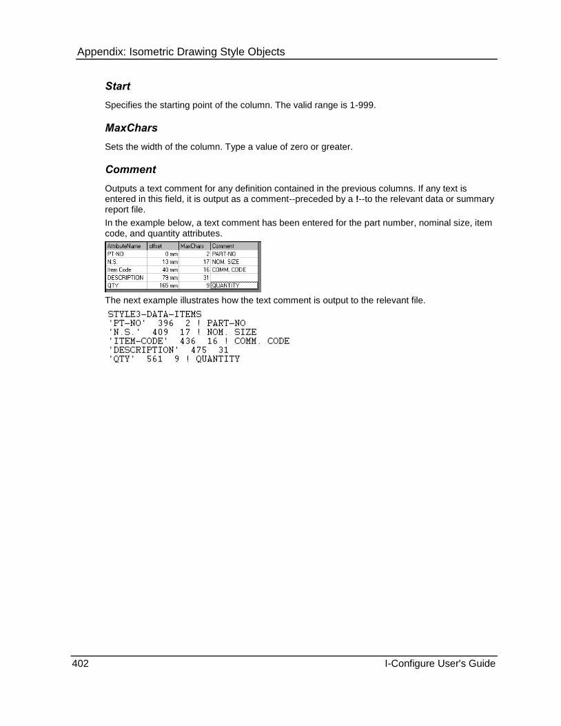
Appendix: Isometric Drawing Style Objects
402 I-Configure User's Guide
Start
Specifies the starting point of the column. The valid range is 1-999.
MaxChars
Sets the width of the column. Type a value of zero or greater.
Comment
Outputs a text comment for any definition contained in the previous columns. If any text is entered in this field, it is output as a comment--preceded by a !--to the relevant data or summary report file.
In the example below, a text comment has been entered for the part number, nominal size, item code, and quantity attributes.
The next example illustrates how the text comment is output to the relevant file.
Appendix: Isometric Drawing Style Objects
I-Configure User's Guide 403
CutList Object Sets options for the cut list, which provides a list of pipes that are cut into smaller lengths during construction.
ActiveList (on page 403)
IncludeAdditionalMaterial (on page 403)
CutPieceID (on page 404)
CutPieceSequence (on page 404)
DecimalInchOutput (on page 404)
LengthToCL (on page 404)
LengthToBranchPoint (on page 404)
OffshoreAllowance (on page 405)
OnShoreAllowance (on page 405)
ShopWeldAllowance (on page 405)
UseWeldGapData (on page 405)
UseTangentData (on page 406)
Visible (on page 406)
The CutList object also contains the following groups of options:
Fixed Layout - Defines the fixed layout cut list format. For more information, see CutList.FixedLayout Object (on page 406).
User Defined - Defines the user-defined cut list format. For more information, see CutList.UserDefined Object (on page 407).
Summary File - Sets options for the cut list summary file. For more information, see CutList.SummaryFile Object (on page 411).
ActiveList Controls the format of the cut list.
Fixed - Use the properties of the FixedLayout object.
UserDefined -Use the properties of the UserDefined object.
See Also CutList.FixedLayout Object (on page 406) CutList.UserDefined Object (on page 407)
IncludeAdditionalMaterial Controls how additional material is handled in the cut list.
None - No entry to cut list for additional material.
Pipe Only - Add entry to cut list for additional material (PIPE).
Misc Only - Add entry to cut list for additional material (MISC).
Pipe and Misc - Add entry to cut list for additional material (PIPE and MISC).
Defines
OS 2 Pos 9

Appendix: Isometric Drawing Style Objects
404 I-Configure User's Guide
CutPieceID Specifies the cut piece identifier type at the appropriate positions along pipelines.
Numeric - Display cut piece identifiers that are numeric.
Alphabetic - Display cut piece identifiers that are alphabetic.
Defines
OS 2 Pos 3
CutPieceSequence Specifies whether cut piece numbers increase across drawings.
Continuous - Increase cut piece numbers across drawings.
Per drawing - Start cut piece numbers at 1 (one) or A on each drawing, depending on the setting of CutPieceID.
Defines
OS 2 Pos 1
See Also CutPieceID (on page 404)
DecimalInchOutput Specifies the output of cut piece lengths in decimal inches for imperial units used.
True - Output supplementary cut lengths in decimal inches format in the REMARKS column of the new style cut piece list. This option only applies to imperial units users.
False - Output standard cut lengths only.
Defines
OS 2 Pos 4
LengthToCL Specifies the calculation of branch cut length. You can specify that the length be measured to the actual branch connection point or to the run centreline.
True - Calculate to the centreline of the main pipeline in all situations.
False - Calculate the cut length to whatever the branch point position implies. That is, no adjustment to cut length is made.
LengthToCL and LengthToBranchPoint are mutually exclusive; setting one to True sets the other one to False.
Defines
OS 2 Pos 5
See Also LengthToBranchPoint (on page 404)

Appendix: Isometric Drawing Style Objects
I-Configure User's Guide 405
LengthToBranchPoint Controls the calculation of branch cut length to the branch point position.
True - Calculate the cut length to whatever the branch point position implies, that is, no adjustment to cut length is made.
False - Calculate to the centreline of the main pipeline in all situations.
LengthToCL and LengthToBranchPoint are mutually exclusive; setting one True sets the other one to False.
Defines
OS 2 Pos 5 = 2
See Also LengthToCL (on page 404)
OffshoreAllowance Sets the amount of extra pipe that is added at loose flange and field fit weld (FFW) positions for offshore piping. Extra pipe is added both to cut pipe length dimensions and to pipe quantities on the isometric drawing.
0 or Blank - Obtain 0 (zero) mm allowance.
Value (real number) - Use the value (in range 0-999) of an alternative allowance.
Defines
OS 22 Pos 4-6
OnShoreAllowance Sets the amount of extra pipe that is added at loose flange and field fit weld (FFW) positions for onshore piping. Extra pipe is added both to cut pipe length dimensions and to pipe quantities on the isometric drawing.
0 or Blank - Obtain 0 (zero) mm allowance.
Value (real number) - Use the value (in range 0-999) of an alternative allowance.
Defines
OS 22 Pos 1-3
ShopWeldAllowance Sets the amount of extra pipe that is added for shop test purposes where certain welds are cut-off together with a short length of pipe after testing.
0 or Blank - Obtain 0 (zero) mm allowance.
Value (real number) - Use the value (in range 0-999) of an alternative allowance.
ShopWeldAllowance is applied only to shop test welds.
Defines
OS 22 Pos 7-9

Appendix: Isometric Drawing Style Objects
406 I-Configure User's Guide
UseWeldGapData If set to True, the data stored in the WeldGaps property at the project level is written to the welding definition file (WDF). This data is used for setting the various weld gaps.
When you import a style, if the WDF contains a WELD-GAPS entry, the WeldGaps and the WeldGapData properties are both set to True.
See Also Import Isometric Style Settings from File (on page 146) WeldGaps (on page 130)
UseTangentData If set to True, the data stored in the ElbowConversion property at the project level is written to the drawing definition file.
If there is data in the ElbowConversion property, then this property must be set to True; otherwise, any cut lengths can be wrong.
When importing a style, if the DDF contains a STANDARD-BEND-LENGTHS entry, the ElbowConversion and the UseTangentData properties are both set to True.
See Also ElbowConversion (on page 131) Import Isometric Style Settings from File (on page 146)
Visible Turns on and off the display of the cut piece list and cut piece identifiers. The cut list is a report on the cut pieces that ISOGEN has determined to be in the pipeline. The type of cut list report can be Fixed or UserDefined.
ActiveList controls which list is used.
True - Show the cut piece list and numbers on the isometric drawing.
False - Suppress the display of cut piece list and numbers on the isometric drawing.
Defines
OS 2 Pos 1
See Also ActiveList (on page 403)
CutList.FixedLayout Object (on page 406)
CutList.UserDefined Object (on page 407)

Appendix: Isometric Drawing Style Objects
I-Configure User's Guide 407
CutList.FixedLayout Object Defines the fixed layout cut list format.
Content (on page 407)
If either of these types of cut list is required, the ActiveList property on the CutList object must be set to Fixed. For more information, see ActiveList (on page 403).
Content
Specifies a limited or full cut list.
Standard - Use the old style cut list with limited information.
Extended - Use the new style cut list with full information.
Defines
OS 2 Pos 2
CutList.UserDefined Object Defines the user-defined cut list format.
The CutList.UserDefined object also contains a collection of options that are used to define the columns for the user defined cut list. For more information, see CutList.UserDefined XYColumns Collection (on page 410).
AllowOverflowDrawings (on page 407)
DrawingLayer (on page 408)
HorizontalDirection (on page 408)
HorizontalSpacing (on page 408)
Layout (on page 408)
MaxColumns (on page 409)
MaxRows (on page 409)
ShowEnclosure (on page 409)
StartX (on page 409)
StartY (on page 409)
TextFont (on page 409)
TextHeight (on page 409)
TextWeight (on page 409)
TextWidthFactor (on page 410)
VerticalDirection (on page 410)
VerticalSpacing (on page 410)
Count (on page 410)
AllowOverflowDrawings
Controls whether the cut list causes an overflow drawing. True is the default setting.
True - Cut list can cause an overflow drawing.
False - Cut list cannot cause an overflow drawing. If AllowOverflowDrawings is set to False, and there was no overflow drawing created for any other reason, then the cut list overflow data is lost.

Appendix: Isometric Drawing Style Objects
408 I-Configure User's Guide
DrawingLayer
Sets the drawing layer for the cut list text. Type an integer in the range 1-50.
HorizontalDirection
Sets the horizontal direction for the cut list. The default setting is Right.
Right - Cut list is to the right.
Left - Cut list is to the left.
HorizontalSpacing
Sets the horizontal spacing required between each column of the cut pipe list output when the table is horizontally formatted or two-dimensional. Type a value (integer).
Layout
Controls whether the table is horizontal, vertical, or multiple style.
SingleVertical - Output same data items vertically against their relevant heading. Number of columns output dependent on MaxRows setting.
SingleHorizontal - Output same data items horizontally against their relevant heading. Number of columns output dependent on MaxRows setting.
MultipleVertical (Across/Down) - Layout of data items is Across > Down. Number of columns output dependent on MaxRows setting.

Appendix: Isometric Drawing Style Objects
I-Configure User's Guide 409
MultipleVertical (Down/Across) - Layout of data items is Down > Across. Number of columns output dependent on the MaxRows property.
See Also MaxRows (on page 409)
MaxColumns
Defines the maximum number of columns before a new row is started when using multiple tables or the maximum number of entries for a single horizontal table. Type a value (integer).
MaxRows
Defines the maximum number of rows before a new column is started when using multiple tables or the maximum number of entries when the table is vertical. Type a value (integer).
ShowEnclosure
Controls whether cut list enclosures are shown.
True - Display cut list enclosures.
False - Suppress the display of cut list enclosures.
StartX
Defines the bottom left X position of the first line of the cut list. Type a value (integer).
StartY
Defines the bottom left Y position of the first line of the cut list. Type a value (integer).
TextFont
Specifies a font corresponding to a font entry in the .fif file. Select an appropriate font from the list.
TextHeight
Sets the height of the text in the cut list. Type a value (as a real number) in mm or inches (as a real number), depending on the setting of the drawing units set on the Options dialog box.
See Also Options (on page 36)
TextWeight
Sets the character thickness. Define a value between 1 and 9. Only used for MicroStation.

Appendix: Isometric Drawing Style Objects
410 I-Configure User's Guide
TextWidthFactor
Defines the ratio of width to height of the text in the cut list. Type a value (integer).
VerticalDirection
Sets the vertical direction for the cut list.
Up - Cut list goes up.
Down - Cut list goes down.
VerticalSpacing
Sets the vertical spacing required between each row of the cut list output when the table is vertically formatted or two dimensional. Type a value in mm or inches (real number), depending on the setting of the drawing units set on the Options dialog box.
See Also Options (on page 36)
Count
Displays the number of columns in the user-defined cut list report plotted on the isometric drawing. This value is defined by the software.
CutList.UserDefined XYColumns Collection
Specifies the columns for the user defined cut list.
AttributeName (on page 393)
AttributeName (on page 411)
Offset (on page 411)
MaxChars (on page 411)
This must be used with a backing sheet, as the positions given are for the X coordinate only.
The value that displays in parentheses after the collection name is a count of how many definitions are stored in the collection.
See Also Add an Item to a Collection (on page 171) Remove an Item from a Collection (on page 172)

Appendix: Isometric Drawing Style Objects
I-Configure User's Guide 411
AttributeName
Specifies the name of the attribute being defined. Use the AttributeName list to select the required attribute.
Offset
Specifies the offset in mm from the StartX and StartY.
Type a value (real number) in mm or inches, depending on the setting of the drawing units set in the Options dialog box.
See Also Options (on page 36)
MaxChars
Sets the width of the column.
Comment
Outputs a text comment for any definition contained in the previous columns. If any text is entered in this field, it is output as a comment--preceded by a !--to the relevant data or summary report file.
In the example below, a text comment has been entered for the part number, nominal size, item code, and quantity attributes.
The next example illustrates how the text comment is output to the relevant file.

Appendix: Isometric Drawing Style Objects
412 I-Configure User's Guide
CutList.SummaryFile Object Sets options for the cut list summary file.
The CutList.SummaryFile object also contains a collection of options that are used to define the columns for a material list summary file. For more information, see CutList.SummaryFile TextColumns Collection (on page 414).
Enabled (on page 412)
Path (on page 412)
Append (on page 412)
UserDefined (on page 412)
FileFormat (on page 413)
Delimiter (on page 413)
HeaderLines (on page 413)
ShowHeaders (on page 413)
TitleText (on page 413)
ShowTitles (on page 413)
Count (on page 414)
Enabled
Specifies whether the summary file is created.
True - Enable the export of cut list summary details to the material list definition (MLD) file.
False - Suppress the export of cut list summary details to the material list definition (MLD) file.
Path
Specifies a path to the summary file. Type the full path and filename.
Do not include special characters in the summary file name.
Append
Defines whether the file is opened in appended mode or overwrite mode.
True - Append the file.
False - Overwrite the file.
UserDefined
Specifies whether the cut list summary file uses the properties of the summary file object to control the data and headings output to the material control file or if the old standard cut list summary file is created.
True - Use the properties of the summary file object.
False - Create the old standard material control file.
Defines
OS 23 Pos 4
See Also CutList.SummaryFile Object (on page 411)

Appendix: Isometric Drawing Style Objects
I-Configure User's Guide 413
FileFormat
Defines the format of the output file.
Fixed - Output a fixed format file.
Delimited - Output a delimited file.
Delimiter
Defines the character used as a delimiter when the file format is delimited. The possible characters are:
Blank
Comma (,)
Semi-colon (;)
Colon (:)
HeaderLines
Specifies the text string for the column header. You must ensure that the column headers match the column positions set in the Material List Definition (MLD) file.
\ - Start a new line.
| - Produce a vertical break.
The HeaderLines width is defined by the length of the last line, terminated with the pipe character (|). The length of the last line should be at least as long as the total width of data to be displayed below it.
Column description text in the HeaderLines field must lie in the column bounds as defined.
You must ensure that the column headers match the column positions set in the material list definition (MLD) file.
ShowHeaders
Controls whether header lines are shown.
True - Display header lines.
False - Suppress the display of header lines.
TitleText
Specifies the text for the title.
ShowTitles
Specifies whether the title line is shown.
True - Display the title line.
False - Suppress the display of the title line.

Appendix: Isometric Drawing Style Objects
414 I-Configure User's Guide
Count
Displays the number of attributes to be output to the material list cut list summary file.
CutList.SummaryFile TextColumns Collection
Stores the definitions of the data to be output to the cut list summary report file. You can define the following properties:
AttributeName (on page 414)
Justification (on page 414)
Start (on page 414)
MaxChars (on page 414)
See Also Add an Item to a Collection (on page 171) Remove an Item from a Collection (on page 172)
AttributeName
Specifies a property to appear in the column
Justification
Sets the alignment of the text. You can choose from left- or right-justified, or numeric.
Start
Specifies the starting point of the column for the output data on a fixed format file, and specifies the field number for a delimited file.
MaxChars
Specifies the maximum number of characters.

Appendix: Isometric Drawing Style Objects
I-Configure User's Guide 415
Comment
Outputs a text comment for any definition contained in the previous columns. If any text is entered in this field, it is output as a comment--preceded by a !--to the relevant data or summary report file.
In the example below, a text comment has been entered for the part number, nominal size, item code, and quantity attributes.
The next example illustrates how the text comment is output to the relevant file.
Supplementary Object Sets options for various input and output files.
The Supplementary object contains the following groups of options:
Additional Data - Defines the DDF file. For more information, see Supplementary.AdditionalData Object (on page 416).
Auxiliary Programs - Lists programs that run before or after ISOGEN. For more information, see Supplementary.AuxiliaryPrograms Object (on page 417).
Bending Report - Activates and configures the bending report. For more information, see Supplementary.BendingReport Object (on page 419).
Centre-of-Gravity - Specifies options about the centre-of-gravity for pipes. For more information, see Supplementary.CentreOfGravity Object (on page 420).
Data Files - Provides the names of input data files that ISOGEN uses in various functions. For more information, see Supplementary.DataFiles Object (on page 422).
Detail Sketches - Defines detail sketches on the isometric drawing. For more information, see Supplementary.DetailSketches Object (on page 445).
Drawing Information File - Stores the definitions for the Drawing Information Cross Reference output file in the DwgInfoFile collection. For more information, see Supplementary.DwgInfoFile Object (on page 453).
Equipment Trim - controls the various functions related to the generation of equipment trim (vessel trim) drawings and associated material control files. For more information, see Supplementary.EquipmentTrim Object (on page 455).
Fonts - Controls the use of the ISOGEN font information file. If required, it can be used to turn Off the use of fonts in the ISOGEN output files. For more information, see Supplementary.Fonts Object (on page 457).
Heat Treatment - Sets up heat treatment /NDE testing data. For more information, see Supplementary.HeatTreatment Object (on page 458).
Instrument SKEYs - Specifies user-defined symbol keys. ISOGEN treats these keys as instruments. For more information, see Supplementary.InstrumentSKEYS Object (on page 460).

Appendix: Isometric Drawing Style Objects
416 I-Configure User's Guide
Neutral File - Controls the basic format and content of the Neutral report file. For more information, see Supplementary.NeutralFile Object (on page 461).
Pipeline Attributes - Defines the PIPELINE-REFERENCE-LOCATION-DEFINITION attribute in the data definition file (DDF). For more information, see Supplementary.PipeLineAtts Object (on page 467).
Printed Material List - Defines the header content of the printed material list. For more information, see Supplementary.PrintedMaterialList Object (on page 492).
Reference Planes - Defines reference planes on the isometric drawing. For more information, see Supplementary.ReferencePlanes Object (on page 470).
Repeat Files - For more information, see Supplementary.RepeatFile Object (on page 473).
Report Files - Provides the names of supplementary output files. For more information, see Supplementary.ReportFiles Object (on page 475).
Site Weld File - Defines the site weld file. For more information, see Supplementary.SiteWeldFile Object (on page 477).
Spool Attributes - Defines the data required for the output of spool attributes data on the isometric and to summary report files, such as the spool Information file. For more information, see Supplementary.SpoolAttributes Object (on page 479).
Spool Information - Stores the definitions for the spool information file in the Columns collection. For more information, see Supplementary.SpoolInformation Object (on page 481).
Table Attributes - Stores the definitions of the DFTable Attributes. For more information, see Supplementary.TableAttributes Object (on page 484).
Title Texts - Specifies user-defined text strings to be plotted on an ISOGEN- generated drawing frame. The Visible option for the drawing frame must be set to False. For more information, see Supplementary.TitleTexts object (on page 487).
Traceability - Defines a unique part numbers table that can be output on the isometric drawing and a traceability output file. For more information, see Supplementary.Traceability Object (on page 488).
Supplementary.AdditionalData Object Defines additional data for the Data Definition file (DDF).
Enabled (on page 416)
DDFLines (on page 417)
Enabled
Controls whether the data in the property DDFLines is added to the Drawing Definition file (DDF).
True - Include the data.
False - Exclude the data.
See Also DDFLines (on page 417)

Appendix: Isometric Drawing Style Objects
I-Configure User's Guide 417
DDFLines
Specifies a block of text to be added to the Data Definition File (DDF). When you double-click the DDFLines data field, the software opens a text editor and displays the current text (if any exists). You can use the text editor to set the data lines to be added to the data definition file.
Click File > Update to add the text, or click File > Cancel to close the text editor without saving the changes.
Supplementary.AuxiliaryPrograms Object Specifies information about pre- and post-processor programs.
StartProgram (on page 417)
StartTimeout (on page 418)
StopOnError (on page 418)
PODGraphicsProgram (on page 418)
PODGraphicsTimeout (on page 418)
EndProgram (on page 418)
StartProgram
Specifies a pre-processor program to run before Personal ISOGEN.
37. Double-click the Value box.
The Specify path for file dialog box appears.
38. Click Browse .
The Browse for file dialog box appears.

Appendix: Isometric Drawing Style Objects
418 I-Configure User's Guide
39. Navigate to the appropriate file, and then click Open.
The path location to the selected file appears in the dialog box.
40. Click OK.
StartTimeout
Defines the number of seconds before the start program is terminated and ISOGEN begins processing. Type the required value (integer). The default time is 60 seconds.
StopOnError
Controls whether Personal ISOGEN runs if the pre-processor program experiences an error and fails.
True - Suppress the running of Personal ISOGEN if the pre-processor fails.
False - Run Personal ISOGEN even if the pre-processor fails.
PODGraphicsProgram
Specifies an external program to run before ISOGEN's output is translated to the final drawing output, which allows you to complete some minor editing of the drawing output.
PODGraphicsTimeout
Specifies the number of seconds before the external program specified by PODGraphicsProgram is terminated and ISOGEN begins processing.
EndProgram
Specifies a post-processor program to run after Personal ISOGEN.
41. Double-click the Value box.
The Specify path for file dialog box appears.
42. Click Browse .
The Browse for file dialog box appears.

Appendix: Isometric Drawing Style Objects
I-Configure User's Guide 419
43. Navigate to the appropriate file, and then click Open.
The path location to the selected file appears in the dialog box.
44. Click OK.
Supplementary.BendingReport Object Controls options for bending pipe reports.
Enabled (on page 419)
Path (on page 419)
Append (on page 400)
ReportContents (on page 419)
Enabled
Controls whether the properties bending report is created.
True - Create the file.
False - Suppress creation of the file.
Path
Provides the path to the Bending peport.
45. Double-click the Value box.
The Specify path for file dialog box appears.
46. Click Browse .
The Browse for file dialog box appears.
47. Navigate to the appropriate file, and then click Open.
The path location to the selected file appears in the dialog box.
48. Click OK.
Append
Defines whether the file is opened in appended mode or overwrite mode.
True - Append the file.
False - Overwrite the file.

Appendix: Isometric Drawing Style Objects
420 I-Configure User's Guide
ReportContents
Determines the information included in the Bending Report.
Standard - Include pipe fabrication information including details of each cut piece, listing the length, diameter, end preparation, material part number, and other related details to assist manufacturing. In addition bending information giving distances to/between bends, angle and radius details are also output.
Full - Include the same pipe fabrication information as with Standard, with the addition of details to enable profiling the shaped ends of pipe and the cutting of holes, such as for tees, olets, crosses, and so on.
Supplementary.CentreOfGravity Object Specifies options for centre-of-gravity and weight calculations.
Enabled (on page 420)
ForDryPipe (on page 420)
ForWetPipe (on page 421)
PerPipeLine (on page 421)
ShowInsulationWeight (on page 421)
ShowWetWeight (on page 421)
Enabled
Controls whether any centre-of-gravity and weight calculations are done.
True - Calculate those centre-of-gravity and weight calculations which are set by ForDryPIpe, ForWetPipe, ShowInsulationWeight and ShowWetWeight.
False - Suppress all four centre-of-gravity and weight calculations.
Defines
OS 82 Pos 1
See Also ForDryPIpe (on page 420) ForWetPipe (on page 421) ShowInsulationWeight (on page 421) ShowWetWeight (on page 421)
ForDryPipe
Controls which centre-of-gravity calculations are done for dry (empty) pipe. Calculated values can then be output on the drawing using text positioning facilities, or output in a Weight/CofG summary report.
Not Required - Centre-of-gravity for dry pipe not required.
Calc C of G - Calculate centre-of-gravity for dry pipe.
Calc C of G with Insulation - Calculate centre-of-gravity for insulated dry pipe.
Calc C of G with and without Insulation - Calculate centre-of-gravity for dry pipe and insulated dry pipe.
Defines
OS 82 Pos 4

Appendix: Isometric Drawing Style Objects
I-Configure User's Guide 421
ForWetPipe
Controls which centre-of-gravity calculations are done for wet (full) pipe. Calculated values can then be output on the drawing using text positioning facilities or output in a Weight/CoG summary report.
Not Required - Centre-of-gravity for wet pipe not required.
Calc C of G - Calculate centre-of-gravity for wet pipe.
Calc C of G with Insulation - Calculate centre-of-gravity for insulated wet pipe.
Calc C of G with and without Insulation - Calculate centre-of-gravity for wet pipe and insulated wet pipe.
Defines
OS 82 Pos 5
PerPipeLine
Controls whether the centre-of-gravity and weight calculations are per pipeline or per drawing/spool.
Enabled must also be set to True.
True - Calculations are per pipeline.
False - Calculations are per drawing/spool.
Defines
OS 82 Pos 1
See Also Enabled (on page 420)
ShowInsulationWeight
Controls whether insulation weight is calculated. Insulation weight can then be output on the drawing using text positioning facilities or in a Weight/CofG summary report.
True - Calculate insulation weight.
False - Suppress the calculation of Insulation weight.
Defines
OS 82 Pos 3
ShowWetWeight
Controls whether wet (full) weight is calculated. Wet weight can then be output on the drawing using text positioning facilities or in a Weight/CofG summary report.
True - Calculate wet weight.
False - Suppress calculation of wet weight.
Defines
OS 82 Pos 2

Appendix: Isometric Drawing Style Objects
422 I-Configure User's Guide
Supplementary.DataFiles Object The Supplementary.DataFile object contains a collection of options that are used to store the names of the input files used by ISOGEN. For more information, see Supplementary.DataFiles ISOGENFiles Collection (on page 422).
Count (on page 451)
Count
Displays the number of data files--input files to be read by ISOGEN--currently defined in the style.
Supplementary.DataFiles ISOGENFiles Collection
Provides the names of input and output data files ISOGEN uses in various functions. For example, ISOGEN can calculate weights of components if a data file containing weight information is available.
FileType (on page 422)
FilePath (on page 423)
FileText (on page 477)
The value that displays in parentheses after the collection name is a count of how many definitions are stored in the collection.
See Also Add an Item to a Collection (on page 171) Remove an Item from a Collection (on page 172)
FileType
Double-click in the FileType data box and then use the FileType list to select the type of input data file. You can choose from the following:
ASCII-SYMBOLS (on page 423) ASCII version of the ISOGEN symbol file.
BENDING-DATABASE-FILE (see "Supplementary.BendingReport Object" on page 419)
Bending, cutting and hole information file.
BINARY-SYMBOLS (on page 424) Binary version of the ISOGEN symbol file.
BOLT-INFORMATION-FILE (on page 424) Bolting information file.
COMPONENT-INFORMATION-FILE (on page 424)
Contains detailed information related to individual components.
FUNCTION-DEFINITION-FILE (on page 425) Defines the content and structure of other files that form part of the Component Information facilities.
INSULATION-WEIGHT-FILE (on page 427) Contains weights of insulation on a bore / unit length basis for each Insulation specification.
PROJECT-MATERIAL-DATA (on page 428) System specified.
PROJECT-MATERIAL-MANAGER (on page 428)
System specified.
PROJECT-PIPELINE (on page 429) System specified.
REMARKS (on page 431) Remarks data file.

Appendix: Isometric Drawing Style Objects
I-Configure User's Guide 423
OPTION-SWITCH-LONG
DRAWING-DEFINITION
POSITIONED-TEXT
ALTERNATIVE-TEXT
MATERIAL-LIST-DEFINITION
WELDING-DEFINITION
TITLE-BLOCK
SPECIAL-INSTRUMENTS
User alternative control files.
User now have the option of specifying an alternative file (in the Supplementar. DataFiles).
SPECIFIC-GRAVITY (on page 431) Contains the specific gravity values for pipeline fluid or gas contents.
FilePath
Defines the file path.
49. Double-click the FilePath box.
50. In the Specify path for file dialog box, navigate to the appropriate file and then click OK.
FileText
51. Double-click the FileText box.
52. In the text editor that displays, edit the data as necessary.
53. Click File > Update to save your changes.
To close the text editor without saving your changes, click File > Cancel.
File Types
ASCII-SYMBOLS
Contains definitions of the user-defined ISOGEN symbols, such as new and re-defined SKEYS. Information in this file is used to override default ISOGEN behavior when plotting shapes in the isometric drawing to represent components in the pipeline.
This item points to the ASCII (human-readable) form of the symbol data. It can be created using the ISOGEN Symbols editor software.

Appendix: Isometric Drawing Style Objects
424 I-Configure User's Guide
BINARY-SYMBOLS
Contains definitions of the user-defined ISOGEN symbols, such as new and re-defined SKEYS. Information in this file is used to override default ISOGEN behavior when plotting shapes in the Isometric drawing to represent components in the pipeline.
This item points to the BINARY (computer-readable) form of the symbol data. It can be created using the ISOGEN Symbols editor software.
BOLT-INFORMATION-FILE
Contains the look up data to allow ISOGEN to produce reports on the bolted connections in the pipeline. For a description of the contents of this file, see FDF BOLTING-INFO-OUTPUT (on page 431).
COMPONENT-INFORMATION-FILE
For each component entry, the COMPONENT-INFORMATION-FILE (CIF) holds the following items of information:
Design contractor's item code (the Item code in the input Piping data file).
Main and secondary component bores.
Main and secondary Thickness/Ratings.
Fabricator's item code.
Fabricator's material description.
Component weight.
This is the maximum amount of information that can be held for each component. What actually appears depends upon what facilities are actually being used.
The structure/layout of the CIF file is defined by the COMPONENT-INFORMATION-FILE Section of the FUNCTION DEFINITION FILE.
CIF Rules Summary
54. Weight data in the CIF takes precedence over weights in the piping data file. However, in the event of missing values, SmartPlant Spoolgen can supplement the data in the CIF by searching the Piping data file.
55. If the CoG facility is to be used, then component weight information must be available in either the CIF or the piping data files.
56. Several ITEM-CODE-IDENTIFIER entries can be made in the CIF to cater to a variety of different Design Contractor or Fabricator item codes. The actual ones to be used are specified in the COMPONENT- INFORMATION-SELECTION section of the FDF file.
57. If you want to handle projects with Metric bore piping data files and Imperial bore piping data files, two sets of N.S. and N.S.SEC information can be included in a CIF, with both projects sharing the one CIF. However, two separate FDFs are required to specify the required N.S. to be used on a particular project.

Appendix: Isometric Drawing Style Objects
I-Configure User's Guide 425
Item Codes in the CIF
Item codes for components in the CIF can be constructed (and specified) in two different ways, as outlined below.
58. In the form of unique codes with built-in bore information:
E.g.
E-90-CS1-40:3 - this is an elbow of 3" bore
E-90-CS1-40:4 - this is the same elbow, but of 4" bore
R-C-CS1-40:4X3 - this is a concentric reducer of bore 4" X 3".
This type of Item code does not need N.S. and N.S.SEC data fields to specify the bore information because this is built-in to the Item code.
59. Codes having separate bores:
E.g.
E-90-CS1-40
R-C-CS1-40
This type of Item code does need N.S. and N.S.SEC data fields to completely identify the component.
There are no rules as to whom should use which of the two types of item code construction. Some Design contractors use the first type.
See Also COMPONENT-INFORMATION-FILE Section (on page 433) FUNCTION DEFINITION FILE. (see "FUNCTION-DEFINITION-FILE" on page 425)
FUNCTION-DEFINITION-FILE
The function definition file (FDF) provides the following functions:
60. It defines the units for:
Lengths
Weights
Nominal sizes
61. It defines the content and structure of other files that form part of the component information facilities, namely:
COMPONENT INFORMATION FILE (CIF) (see "COMPONENT-INFORMATION-FILE" on page 424)
INSULATION WEIGHT FILE (IWF) (see "INSULATION-WEIGHT-FILE" on page 427)
SPECIFIC GRAVITY FILE (SGF) (see "SPECIFIC-GRAVITY" on page 431)
62. Through a system of cross-reference pointers in the COMPONENT-INFORMATION-SELECTION Section, (see "COMPONENT-INFORMATION-SELECTION Section" on page 436) it defines the functions of the various columns of data in the COMPONENT INFORMATION FILE (see "COMPONENT-INFORMATION-FILE" on page 424) .

Appendix: Isometric Drawing Style Objects
426 I-Configure User's Guide
63. Bend Radius (see "MISC-DEFINITIONS Section" on page 437) identification.
64. The format of the Weight and C of G summary file (see "WEIGHT/COFG-SUMMARY-FILE Section" on page 442) .
65. Definition of IDF changes (see "IDF-REVISIONS Section" on page 436) - where nominated IDF record types can have their normal use either changed or deleted.
66. The format of the
Bolting output (see "BOLTING-INFO-OUTPUT" on page 431)
Pipeline attribute file (see "PIPELINE-ATTRIBUTE-FILE" on page 427)
HeatTreatment/NDE file (see "HEATTREATMENT/NDE-FILE" on page 426)
Site Assembly report (see "SITE-ASSEMBLY-REPORT" on page 438)
Spool attribute file (see "SPOOL-ATTRIBUTE-FILE" on page 441)
The FDF has several sections, each having a keyword identifier
UNITS-DEFINITION (see "UNITS-DEFINITION Section" on page 441)
COMPONENT-INFORMATION-FILE (see "COMPONENT-INFORMATION-FILE Section" on page 433)
COMPONENT-INFORMATION-SELECTION (see "COMPONENT-INFORMATION-SELECTION Section" on page 436)
INSULATION-WEIGHT-FILE (see "INSULTATION-WEIGHT-FILE Section" on page 437)
SPECIFIC-GRAVITY-FILE (see "SPECIFIC-GRAVITY-FILE Section" on page 438)
MISC-DEFINITIONS (see "MISC-DEFINITIONS Section" on page 437)
WEIGHT/COFG-SUMMARY-FILE (see "WEIGHT/COFG-SUMMARY-FILE Section" on page 442)
IDF-REVISIONS (see "IDF-REVISIONS Section" on page 436)
BOLTING-INFO-OUTPUT (on page 431)
PIPELINE-ATTRIBUTE-FILE (on page 427)
HEATTREATMENT/NDE-FILE (on page 426)
SITE-ASSEMBLY-REPORT (on page 438)
SPOOL-ATTRIBUTE-FILE (on page 441)
Each of these sections has its own list of data inputs.
HEATTREATMENT/NDE-FILE
This FDF section defines the format of the HeatTreatment/NDE file, which must be defined in the Supplementary Datafiles ISOGENFiles collection.
The section heading HEATTREATMENT/NDE-FILE is followed by the following identifiers and associated data:
DELIMITER-CHARACTER data - Where data specifies the delimiter used in the HeatTreatment/NDE attribute file. (Optional).
IGNORE_CHARACTER data - Where data is any character that should be ignored when the software is extracting data for the HeatTreatment/NDE attribute file if it is a delimited file. (Optional).

Appendix: Isometric Drawing Style Objects
I-Configure User's Guide 427
Data Items - The data items are the -900 to -999 series text type record identifiers, followed by either start-col,. end-col,. or position in file dependent upon whether a delimiter character is set. The data after the ! is a comment for user information, as shown in the following example:
FUNCTION-DEFINITION-FILE
HEATTREATMENT/NDE-FILE
DELIMITER-CHARACTER ,
-950 2 ! PWHT N.S. RANGE
-951 3 ! PWHT TEMPERATURE
-952 4 ! PREHEAT N.S RANGE
-953 5 ! PREHEAT TEMPERATURE
-954 6 ! % RT
-955 7 ! % MT
-956 8 ! % PT
-957 9 ! % BHN
See Also Supplementary.Datafiles ISOGENFiles Collection (on page 422)
INSULATION-WEIGHT-FILE
Contains weights of insulation on a bore/unit length basis for each insulation specification. This is needed if Insulation weights are to be calculated and output.
CAL199 1/2 1.04
CAL199 3/4 1.04
CAL199 1 1.04
CAL199 1.1/4 1.04
CAL199 1.1/2 1.19
CAL199 2 1.49
CAL199 2.1/2 1.63
OPTION-SWITCH-OVERRIDE
You can specify an OPTION-SWITCH-OVERRIDE file, which can contain specific values for particular option switches:
130 6
139 12
The switches in the previous example override any value output by I-Configure. Alternatively, switch positions can be specified using a * to indicate an unchanged switch position.
For example, to set switch 1 position 3 to 4, type the following in the file:
1 4**
Likewise, to set switch 10 position 5 to 1, and position 2 to 3, type the following:
10 1**3*

Appendix: Isometric Drawing Style Objects
428 I-Configure User's Guide
PIPELINE-ATTRIBUTE-FILE
This FDF section defines the format of the Pipeline attributes file, which must be defined in the Supplementary Datafiles ISOGENFiles collection. The section heading PIPELINE-ATTRIBUTE-FILE is followed by the following identifiers and associated data.
DELIMITER-CHARACTER data - Where data specifies the delimiter used in the Pipeline attribute file. (Optional).
IGNORE_CHARACTER data - Where data is any character that should be ignored when the program is extracting data for the Pipeline attribute file if it is a delimited file. (Optional).
The data items are the -900 to -999 series text type record identifiers, followed by either start-col. end-col. or position in file dependent upon whether a delimiter character is set. The data after the ! is a comment for user information.
FUNCTION-DEFINITION-FILE
PIPELINE-ATTRIBUTE-FILE
DELIMITER-CHARACTER ,
-900 1 ! LINE REF.
-901 2 ! P-ID FROM
-902 3 ! P-ID TO
-903 4 ! UNIT NO.
-904 5 ! SERVICE CODE
-905 6 ! PAINT CODE
-906 7 ! OPERATING TEMP.
-907 8 ! DESIGN TEMP.
-908 9 ! OPERATING PRESSURE
-909 10 ! DESIGN PRESSURE
-910 11 ! TEST PRESSURE
-911 12 ! TEST TYPE
-912 13 ! INSULATION THKS.
-913 14 ! HEAT TRACING
-914 15 ! INSULATION CODE
-915 16 ! DESIGN CODE
-916 17 ! MATERIAL
If the pipeline attribute mechanism is being used, do not add the same record to the project defaults. Doing so overwrites the data when the isometric is being created by the data in the Pipeline attributes file.
See Also Project Defaults (see "Project Defaults Tab (Project Defaults Dialog Box)" on page 102) Supplementary.Datafiles ISOGENFiles Collection (on page 422)
PROJECT-MATERIAL-DATA
The file contains data to add to, or override the information in the SystemMaterialData.xml file. This defines the available component types, SKEYs, PCF data and groups (and the mapping between them) for use in other software, such as SmartPlant Isometrics and SmartPlant Spoolgen.
This item only needs to be set on one of the mandatory import styles – such as SGImport or ISImport - if such a file has been created for use on a particular project.

Appendix: Isometric Drawing Style Objects
I-Configure User's Guide 429
PROJECT-MATERIAL-MANAGER
The file contains data that adds to or overrides the information in the SystemMaterialManager.xml file. This defines the attributes available for materials used in other software. This item only needs to be set on one of the mandatory import styles – such as SGImport or ISImport - if such a file has been created for use on a particular project.
PROJECT-PIPELINE
The file contains data that adds to or overrides the information in the SystemPOD.xml file. This defines the attributes available for different objects, such as pipelines, components, and welds, that are used in other products.
By default, this item is set on the mandatory SGImport and ISImport styles delivered with SmartPlant Isometrics and SmartPlant Spoolgen respectively. This setting should not normally be changed.
REFERENCE-PLANE-DEFINITION
ISOGEN can be configured to display the coordinates of nominated points in the pipeline relative to a reference plane, rather than as absolute values. The nominated points are indicated by the presence of LOCATION-POINT entries in the PCF. The reference plane can be a set of steel columns and floor levels in a process plant, or it can be a set of decks and bulkheads in a ship.
The reference planes are defined in a file and properties of this object are used to control how ISOGEN behaves when plotting the location points. A location point table can be defined and plotted on the isometric drawing. Optionally, location points can be shown with coordinates.
Six AlternateText numbers have been assigned to output relative directions.
-443 ^ + ? (used for positive relative position in e/w plane).
-444 ^ - ? (used for negative relative position in e/w plane).
-445 ^ + ? (used for positive relative position in n/s plane).
-446 ^ - ? (used for negative relative position in n/s plane).
-447 ^ + ? (used for positive relative position in u/d plane).
-448 ^ - ? (used for negative relative position in u/d plane).
^ is substituted with the reference plane name.
? is substituted with the distance from the reference plane.
An AlternateText record has been assigned to be output as a delimiter text between the relative direction and its relative position.

Appendix: Isometric Drawing Style Objects
430 I-Configure User's Guide
-449 = (default setting)
–449 AlternateText set to blank only outputs the relative position.
See Also Supplementary.ReferencePlanes Object (on page 470)

Appendix: Isometric Drawing Style Objects
I-Configure User's Guide 431
REMARKS
The Remarks file contains a set of texts (remarks) that can be associated with components in the pipeline by setting the Remark property. The file has the following format:
Remark# Remark
1 Remark1
2 Remark2
SPECIFIC-GRAVITY
Contains the specific gravity values for pipeline fluid or gas contents. Each pipeline in the project needs to have an entry in this file if the weight of full--or wet weight--pipelines are required to be output.
4"-DDE-4325 1.1
4"-ARR-6000 1.0
6"-ASC-6900 1.2
FDF Sections
BOLTING-INFO-OUTPUT
This FDF section defines the format of the output for Bolted connections on the Erection operations list.
The section heading BOLTING-INFO-OUTPUT is followed by the following three sub-section headings, each of which has its own data items:
BOLTING-INFO-CONTROLS
List - (MANDATORY) The form of list to be output, either:
CONTINUOUS-DOWN
CONTINUOUS-UP
Start Position - (MANDATORY) Information to identify the START - POSITION for the output of the bolting Information (where X pos and Y pos are input in mm--real (one decimal place) or integer, such as 225, or 225.0, or 225.5).
START-POSITION X pos Y pos
Vertical Spacing - (MANDATORY) The vertical spacing required between each horizontal line of text on the bolting information list (where value is input in mm--real (one decimal place) or integer, such as 6, 6.0, or 6.2).
VERTICAL-SPACING value
Max Number of Lines - (MANDATORY) The maximum number of output lines that can fit on the backing sheet (where the value is an integer number).
MAXIMUM-ENTRIES value
Text Height - The height of the characters in the text to be output on the bolting information list (where value is real (one decimal place) or integer, such as 2, 2.0, or 2.3_)
TEXT-HEIGHT value (in mm)
Drawing Layer - (OPTIONAL) Identification of the drawing layer for outputting the text on to (where value is an integer number that is valid for the graphics system being used).
DRAWING-LAYER value
Text Thickness (Weight) - (OPTIONAL) Identification of the text thickness (weight) for all output text to the bolting information list (where value is an integer number that is valid for the graphics system being used).
TEXT-THICKNESS value

Appendix: Isometric Drawing Style Objects
432 I-Configure User's Guide
Consider the following example:
BOLTING-INFO-OUTPUT - - - - - - - Section Header
BOLTING-INFO-CONTROL
CONTINUOUS-DOWN
START-POSITION 450.0 106.0
VERTICAL-SPACING 4.0
TEXT-HEIGHT 2.5
MAXIMUM-ENTRIES 12
DRAWING-LAYER 16
TEXT-THICKNESS 2
BOLTING-DATA-ITEMS
BOLT-SET NO - Bolted connection number - generated by the system.
N.S. - Nominal size at bolted connection. Output in this format: - 4" = 040.
BOLT-UP-TYPE - One of these values from the related piping specification entry in the bolting information file (-146 type).
HT HW MW NW
BOLT-DIA - Diameter of the bolts used for the flanged connection. Taken from the 115 bolt record in the IDF. Output in this format: - ½" = 050 ¾" = 007 1" = 010.
BOLT-QUANTITY - Number of bolts required for the flanged connection. Taken (two digits) from the 115 bolt record in the IDF.
TENSION-A: Any value set in the BIF (-146) file against the relevant piping specification / size combination.
TENSION-B: Any value found to go into relevant column on operations list.
TORQUE-SETTING
Each of the previous is followed by the X position for location on the drawing frame.
Consider the following example:
BOLTING-INFO-DATA-ITEMS
'BOLT-SET-NO' 450.0
'N.S.' 463.0
'BOLT-UP-TYPE' 486.0
'BOLT-DIA' 504.0
'BOLT-QUANTITY' 522.0
'TENSION-A' 540.0
'TENSION-B' 558.0
'TORQUE-SETTING 576.0
BOLTING-INFO-FILE
'PIPING–SPEC‟ Start Col End Col
„MIN–N.S.‟ Start Col End Col
„MAX–N.S.‟ Start Col End Col
„BOLT–UP–TYPE‟ Start Col End Col
„TENSION–A‟ Start Col End Col
„TENSION–B‟ Start Col End Col
„TORQUE–SETTING‟ Start Col End Col

Appendix: Isometric Drawing Style Objects
I-Configure User's Guide 433
Where Start Col and End Col indicate the extremities of each data column in the file.
MIN“N.S. and MAX-N.S. - Must be stated in the Units specified at the top of the FDF file.
BOLT“UP“TYPE - Must be one of the following:
HT = Hydraulic Tensioner
HW = Hydraulic Wrench
MW = Manual Torque Wrench
NW = Non Mandatory (Hand Tightening)
TENSION-A, TENSION“B or TORQUE“SETTING -
All entries on the list are triggered by the presence of a Bolt Record (-115 type) in the IDF or the attribute BOLT in a PCF.
Each bolted connection is indicated on the isometric using the following properties:
SiteAssemblyIDs (on page 268)
SiteAssemblyIDEnclSize (on page 268)
SiteAssemblyIDsPerDrawing (on page 268)
SiteAssemblyIDEnclosure (on page 266)
The site assembly uses AText -478, default J to prefix the flange assembly identification (J1 or JA).
Considering the following example:
BOLTING–INFO–FILE
„PIPING–SPEC‟ 1 12
„MIN–N.S.‟ 15 20
„MAX–N.S.‟ 23 29
„BOLT–UP–TYPE‟ 32 33
„TENSION–A‟ 35 45
„TENSION–B‟ 50 60
„TORQUE–SETTING‟ 65 75
See Also SITE-ASSEMBLY-REPORT (on page 438)
COMPONENT-INFORMATION-FILE Section
This FDF Section provides a cross-reference to entries in the Component Information File (CIF) by defining the layout and content of that file.
The section heading COMPONENT-INFORMATION-FILE is followed by the following identifiers and associated data.
ITEM-CODE-IDENTIFIER
N.S.
N.S.SEC
N.S.THIRD
N.S.THICKNESS/RATING
N.S.SEC.THICKNESS/RATING
N.S.WALL-THICKNESS
N.S.SEC.WALL-THICKNESS
DESCRIPTION
COMPONENT-WEIGHT
COMPONENT-CONTENT-WEIGHT
EQUIVILANT-INSULATION-LENGTH
N.S.CONVERSION-CODE

Appendix: Isometric Drawing Style Objects
434 I-Configure User's Guide
RADIUS-DIAMETERS
RADIUS-MM
RADIUS-INCH
DETAILED-SKETCH
INFORMATION-NOTE
COMPONENT-ATTRIBUTE1 to COMPONENT-ATTRIBUTE10 (-190 tom -199)
MATERIAL-ATTRIBUTE1 to MATERIAL-ATTRIBUTE10 (-80 to -89)
User Defined Names matching those used in the PCF file
DELIMITER-CHARACTER data - Where data specifies the delimiter used in the Component Information File (see "COMPONENT-INFORMATION-FILE" on page 424).
Each of the following is followed by either start-col. end-col. or position in file, depending on whether a delimiter character is set.
FDF Identifier Used For Used For
ITEM-CODE-IDENTIFIER 1) Design contractors item code.
2) Fabricator's item code.
2) Fabricator's item code.
N.S. The main bore of a component - specified in accordance with the UNITS-BORE Identifier in the UNITS-DEFINITION section of the FDF.
The main bore of a component - specified in accordance with the UNITS-BORE Identifier in the UNITS-DEFINITION section of the FDF.
N.S.SEC The secondary bore of a component - specified in accordance with the UNITS-BORE Identifier in the UNITS-DEFINITION section of the FDF.
The secondary bore of a component - specified in accordance with the UNITS-BORE Identifier in the UNITS-DEFINITION section of the FDF.
N.S.THIRD A third bore of a component - specified in accordance with the UNITS-BORE Identifier in the UNITS-DEFINITION section of the FDF.
A third bore of a component - specified in accordance with the UNITS-BORE Identifier in the UNITS-DEFINITION section of the FDF.
N.S.THICKNESS/RATING Thickness/Rating for the main bore of a component.
Thickness/Rating for the main bore of a component.
N.S.SEC.THICKNESS/RATING
Thickness/Rating for the secondary bore of a component.
Thickness/Rating for the secondary bore of a component.
N.S.OUTSIDE-DIAMETER The outside diameter of the main bore of the component.
The outside diameter of the main bore of the component.
N.S.SEC.OUTSIDE-DIAMETER
The outside diameter of the secondary bore of the component.
The outside diameter of the secondary bore of the component.
N.S.WALL-THICKNESS The wall thickness of the main bore of the component.
The wall thickness of the main bore of the component.
N.S.SEC.WALL-THICKNESS The wall thickness of the secondary bore of the component.
The wall thickness of the secondary bore of the component.
DESCRIPTION Fabricator's Material descriptions. Fabricator's Material descriptions.
COMPONENT-WEIGHT The weight of a component - in the weight units specified in accordance with the UNITS-WEIGHT Identifier in the UNITS- DEFINITION section of the FDF.
The weight of a component - in the weight units specified in accordance with the UNITS-WEIGHT Identifier in the UNITS- DEFINITION section of the FDF.

Appendix: Isometric Drawing Style Objects
I-Configure User's Guide 435
FDF Identifier Used For Used For
COMPONENT-CONTENT-WEIGHT
The weight of the components water volume specified in accordance with the UNITS-WEIGHT Identifier in the UNITS- DEFINITION section of the FDF. For PIPE the weight specified here‟s the weight per unit length for the length units specified in the UNITS-LENGTH Identifier in the UNITS-DEFINITION section of the FDF.
The weight of the components water volume specified in accordance with the UNITS-WEIGHT Identifier in the UNITS- DEFINITION section of the FDF. For PIPE the weight specified here‟s the weight per unit length for the length units specified in the UNITS-LENGTH Identifier in the UNITS-DEFINITION section of the FDF.
EQUIVILANT-INSULATION-LENGTH
Used to equate the component insulation weight to a length based weight. Values here are the equivalent length of insulation in accordance with the weight and length units in the UNITS- LENGTH and UNITS-WEIGHT Identifiers in the UNITS- DEFINITION section of the FDF.
Used to equate the component insulation weight to a length based weight. Values here are the equivalent length of insulation in accordance with the weight and length units in the UNITS- LENGTH and UNITS-WEIGHT Identifiers in the UNITS- DEFINITION section of the FDF.
N.S.CONVERSION-CODE
This is used where the N.S. and N.S. Header output on the Weld list and Weld summary outputs is to be replaced by a user supplied code.
This is used where the N.S. and N.S. Header output on the Weld list and Weld summary outputs is to be replaced by a user supplied code.
RADIUS-DIAMETERS Bend radius specified as a number of diameters.
Bend radius specified as a number of diameters.
RADIUS-MM Bend radius specified in mm. Bend radius specified in mm.
RADIUS-INCH Bend radius specified in mm. Bend radius specified in mm.
DETAILED-SKETCH Detail sketch file name. Detail sketch file name.
INFORMATION-NOTE Information note name. Information note name.
COMPONENT-ATTRIBUTE1 to
COMPONENT-ATTRIBUTE10
Data for Component attributes. Data for Component attributes.
MATERIAL-ATTRIBUTE1 to MATERIAL- ATTRIBUTE10
Data for Material attributes. Data for Material attributes.
User-defined names matching those used in the PCF file.
Data for user-defined names. Data for user-defined names.
The actual number of these data items present will depend upon which of the available facilities are being used.
The maximum width of the file is 500 characters and any characters outside this limit are ignored.

Appendix: Isometric Drawing Style Objects
436 I-Configure User's Guide
COMPONENT-INFORMATION-SELECTION Section
This FDF section provides a link between the Design contractor's item code that appears in the Piping data file and the location of the corresponding entry for that component in the COMPONENT INFORMATION-FILE. (see "COMPONENT-INFORMATION-FILE" on page 424)
This FDF section defines:
Design Contractors Item Code
Alternative Item Code
Alternative Description
The section heading COMPONENT-INFORMATION-SELECTION is followed by the following Identifiers:
ITEM-CODE-INPUT data
ITEM-CODE-OUTPUT data
DESCRIPTION data
Where data is either a start column or file position, dependant upon whether the Component Information file is a delimited file or not.The minimum requirement in this section is the Input Item code:
COMPONENT-INFORMATION-SELECTION (section identifier)
ITEM-CODE-INPUT 1
Alternatively, if Item Code Transposition and Material Description Substitution were being used, the file would look like this:
COMPONENT-INFORMATION-SELECTION (section identifier)
ITEM-CODE-INPUT 1
ITEM-CODE-OUTPUT 51
DESCRIPTION 76
Or for a Delimited file.
COMPONENT-INFORMATION-SELECTION (section identifier)
ITEM-CODE-INPUT 1
ITEM-CODE-OUTPUT 7
DESCRIPTION 10

Appendix: Isometric Drawing Style Objects
I-Configure User's Guide 437
IDF-REVISIONS Section
The IDF-REVISIONS FDF section allows you to delete or change the meaning of the numeric record identifiers that are present in all IDFs in order to make them fully compatible with ISOGEN. This facility is particularly useful to those customers who use the Component Information facility, but who are handling non-standard Alias IDFs, such as IDFs generated by PDMS.
The IDF-REVISIONS section heading is followed by one or several of these entries, depending on what manipulation of records needs to be performed:
DELETE-RECORD data - Where data = any invalid record number that is to be ignored.
CHANGE-RECORD data1 data2 - Where data1 = any invalid record number and data2= the replacement record number for data1.
REDEFINED-SKEY data1 data2 - Where data 1 is the SKEY in the IDF file and data2 is the SKEY to be used instead.
The previous examples are for illustrative purposes only--do not use them. If you need assistance, contact Intergraph Support.
IDF-REVISIONS
DELETE-RECORD -900
CHANGE-RECORD 707 877
REDEFINED-SKEY LWWN FLWN
INSULTATION-WEIGHT-FILE Section
This FDF section provides a cross reference to entries in the insulation weight file (IWF) by defining the layout and content of that file.
The INSULATION-WEIGHT-FILE section heading can be followed by the following identifiers and associated data:
DELIMITER-CHARACTER data - Where data specifies the delimiter used in the insulation weight file, as shown in the following example:
INSULATION-WEIGHT-FILE
DELIMITER-CHARACTER :
INSULATION-SPECIFICATION 1
N.S. 2
INSULATION-WEIGHT 3
Start-col. End-col. - Position in the file dependent upon whether a delimiter character is set, as shown in the following example:
INSULATION-WEIGHT-FILE
INSULATION-SPECIFICATION 1 14
N.S. 15 24
INSULATION-WEIGHT 25 34

Appendix: Isometric Drawing Style Objects
438 I-Configure User's Guide
MISC-DEFINITIONS Section
This FDF section is for facilities that do not warrant their own separate section. Currently, it is only used to define BEND RADIUS values.
The input structure in this FDF section is a section heading:
MISC-DEFINITIONS
followed by the bend radius definition:
BEND-RADIUS data units
where
data = the pipe bend radius.
units = Inch or mm, when radius is a value, and D when the radius is a number of pipe diameters.
Consider the following:
MISC-DEFINITIONS
BEND-RADIUS 5 D
Other typical data inputs are:
BEND-RADIUS 3 D
BEND-RADIUS 5.5 D
BEND-RADIUS 12 INCH
BEND-RADIUS 18.5 INCH
BEND-RADIUS 220 MM
BEND-RADIUS 1250 MM
Bend radius information is used by both the CofG and weights facilities.
SPECIFIC-GRAVITY-FILE Section
This FDF section provides a cross reference to entries in the specific gravity file (SGF) by defining the layout and content of that file.
The SPECIFIC-GRAVITY-FILE section heading is followed by the following identifiers and associated data.
DELIMITER-CHARACTER data - Where data specifies the delimiter used in the specific gravity file .
PIPELINE-REFERENCE - Followed by either start-col. end-col. or position in file, depending on whether a delimiter character is used.
SPECIFIC-GRAVITY - Followed by either start-col. end-col. or position in file, depending on whether a delimiter character is used.
Start col. end col. Example
SPECIFIC-GRAVITY-FILE
PIPELINE-REFERENCE 1 20
SPECIFIC-GRAVITY 21 30
Delimiter Example
SPECIFIC-GRAVITY-FILE
DELIMITER-CHARACTER :
PIPELINE-REFERENCE 1
SPECIFIC-GRAVITY 2

Appendix: Isometric Drawing Style Objects
I-Configure User's Guide 439
SITE-ASSEMBLY-REPORT
This FDF section defines the format of the output for the Site assembly report.
The section heading SITE-ASSEMBLY-REPORT is followed by two sub-section headings:
SITE-ASSEMBLY-REPORT-COLUMN-HEADINGS - The column headings are arranged and spaced out just as they are required to appear in the output report file, as shown in the following example:
SITE-ASSEMBLY-REPORT
SITE-ASSEMBLY-REPORT-COLUMN-HEADINGS
LINEREF DRG ASSY NS BOLT NO ASSY
NO NO DIA OFF ATT1
The column headings look out of line in the example as the space character is narrower than an actual character.
SITE-ASSEMBLY-REPORT-DATA-ITEMS - Permissible data items are:
Unique Name IDF Record Number
PIPELINE-REFERENCE -6
DRG -
REVISION -8
BATCH -10
AREA -10
PROJECT-IDENTIFIER -9
PIPING-SPEC -11
NOMINAL-CLASS -12
NOMINAL-RATING -12
DATE-DMY -14
INSULATION-SPEC -15
TRACING-SPEC -16
PAINTING-SPEC -17
PIPELINE-TEMP -19
MISC-SPEC1 -41
MISC-SPEC2 -42
MISC-SPEC3 -43
MISC-SPEC4 -44
MISC-SPEC5 -45
BOLT-SET-NO -
N.S. -
BOLT-UP-TYPE -
BOLT-DIA
BOLT-QUANTITY -
TENSION-A -
TENSION-B -

Appendix: Isometric Drawing Style Objects
440 I-Configure User's Guide
Unique Name IDF Record Number
TORQUE-SETTING -
ATTRIBURE0 to ATTRIBUTE99 -600 to -699
ATTRIBUTE100 to ATTRIBUTE199 -900 to -999
ASSEMBLY-ATTRIBUTE1 to ASSEMBLY- ATTRIBUTE10
-190 to -199
Consider the following example:
SITE-ASSEMBLY-REPORT-DATA-ITEMS
'PIPELINE-REFERENCE' 1 L
'DRG' 10 L
'BOLT-SET-NO' 15 L
'N.S.' 21 L
'BOLT-DIA' 26 L
'BOLT-QUANTITY' 36 L
'ASSEMBLY-ATTRIBUTE1' 45 L
All the above is carried out in I-Configure, the Assembly attribute is set in the software (SmartPlant Spoolgen) by selecting each bolt and then setting the value for the Assembly attribute on that bolt.
The data items BOLT-UP-TYPE, TENSION-A, TENSION-B and TORQUE-SETTING require the bolting info file (BOLTING-INFO-OUTPUT section of FDF).
See Also
BOLTING-INFO-OUTPUT (on page 431)

Appendix: Isometric Drawing Style Objects
I-Configure User's Guide 441
SPOOL-ATTRIBUTE-FILE
This FDF section defines the format of the spool attribute file, which must be defined in the Supplementary Datafiles ISOGENFiles collection.
The SPOOL-ATTRIBUTE-FILE section heading is followed by the following identifiers and associated data.
DELIMITER-CHARACTER data - Where data specifies the delimiter used in the Spool attribute file. (Optional).
IGNORE_CHARACTER data - Where data is any character that should be ignored when the program is extracting data for the Spool attribute file if it is a delimited file. (Optional).
The data items are -28, -91, -170 to -179, followed by either start-col. end-col. or position in file, depending on whether a delimiter character is set. This can be followed by an ! as a comment for user information.
Consider the following example:
SPOOL-ATTRIBUTE-FILE
DELIMITER-CHARACTER ;
IGNORE-CHARACTER “
-28 1 ! Spool Name
-170 2 ! Spool Attribute 1
-171 3 ! Spool Attribute 2
See Also Supplementary.Datafiles ISOGENFiles Collection (on page 422)
UNITS-DEFINITION Section
This FDF section defines the following units for data items listed in the COMPONENT-INFORMATION-FILE (CIF):
Unit Length
Weight
Nominal Size (N.S.)
The section heading UNITS-DEFINITION is followed by the following identifiers and associated data.
UNITS-BORE data - Where data = Inch or mm.
UNITS-LENGTH data - Where data = Foot (Weights / Foot) or Metre (Weights / Metre).
UNITS-WEIGHT data - Where data = Kgs. or Lbs.
Consider the following example:
UNITS-DEFINITION
UNITS-BORE INCH
UNITS-LENGTH METRE
UNITS-WEIGHT KGS

Appendix: Isometric Drawing Style Objects
442 I-Configure User's Guide
Input Data Formats
Inch bores - You can type 1/2, 0.1/2, 0.5, 1, 1.0, 1.1/2, 1.5, 2, 10 (1 1/2 is also permitted for 1½).
mm bores - You can type. 50 or 50.0.
Weights - You can type. 25 or 25.0
Units Selection Process
Usually, it is expected that the units' settings in OS 41 and the FDF match, as they should do. However, if they do not match, the following sequence is followed.
Units for Weights & Lengths - The units specified in OS 41 are regarded as the master units. For example, if OS 41 specifies weights in LBS but the weights in the CIF are kgs, then all kgs values are converted to lbs. on output. A similar procedure is applied to length units.
Units for N.S. - The unit settings in the FDF and Piping data file must be the same. A check is performed between the N.S. units as defined by O.S.41 and the UNITS-BORE attribute in the FDF. If they differ, the run is terminated with Error Code 35:1126.
WEIGHT/COFG-SUMMARY-FILE Section
This FDF Section defines the required content and layout structure of the weight and centre-of-gravity printed output summary file.
The input definition for this section is in three separate parts:
SUMMARY-FILES-TITLES
The section heading SUMMARY-FILE-TITLES is followed by the title data. There are two different types of title data information items:
67. Variable user-defined descriptive title text, such as PROJECT NO. or AREA REF.
68. Fixed data items. These are standard keywords or equivalent I/D numbers that are used to describe a required data field. They are written inside single quote marks ( ' ' ) to distinguish them from the variable user-defined title text.
The two types are used together to make-up the required file heading.
The following rules apply to the title data section SUMMARY-FILE-TITLES text:
Both user-defined descriptive title text and fixed keyword text are positioned in the output file on the exact line and in the column position at which they are input.
User-defined descriptive title text can be written in upper- or lower- case characters and is re-produced as specified in this respect.
Fixed data items can be defined either as keywords written in upper-case characters and enclosed in single quotes, or can be represented by their standard text record numbers (inside single quotes).
Empty lines for spacing purposes are created by the instruction Blank.
Use the characters ' ' in conjunction with the word PAGE to obtain page numbers. For example, PAGE ' ' automatically produces PAGE 1, PAGE 2, and so on, at the top of each printed output page.

Appendix: Isometric Drawing Style Objects
I-Configure User's Guide 443
SUMMARY-FILE-COLUMN-HEADINGS
The section heading SUMMARY-FILE-COLUMN-HEADINGS is followed by the column headings data (this section is optional).
All column headings data are reported in the output file exactly as it is specified in the FDF. The text should be positioned to suit the data items layout that follows it.
SUMMARY-FILE-DATA-ITEMS
The section heading SUMMARY-FILE-DATA-ITEMS is followed by the data item entries. Each data item entry in this part of the FDF is input using either two, three, or five parameters, depending on the type of data item being specified.
C of G with a vertical layout uses three parameters.
C of G with a horizontal layout uses five parameters.
All others including weight output use two parameters.
The first part is a keyword that must be enclosed in single quotes ( ' ' ).
Typical entries would appear like this:
Most keywords have an equivalent numeric identifier which can be used as an alternative to the text. For example, the numeric equivalent of PIPELINE-REFERENCE is -6.
Numbers, when used, must also be enclosed by single quotes ' '.
Character justification letters.
L Left
R Right
N Number (the column position in this case is the decimal)
V Vertical output

Appendix: Isometric Drawing Style Objects
444 I-Configure User's Guide
For example:
E3252
N1020
EL -1566
H Horizontal output
For example:
E3252 N1020 EL -1566
V and H parameters are only used on C of G output data because this type of data has three output values, not one, and their output layout direction must be specified. The V parameter gives an automatic Vertical layout but where Horizontal justification is specified, extra starting column information must be given one for each C of G output value, as shown in the following example:
'COFG-POSITION-DRY' 44 58 72 L H
Data items available for output in the WEIGHT/COFG-SUMMARYFILE.
Key Name Equivalent I/D Number Equivalent I/D Number
AREA or BATCH -10 -10
COFG-POSITION-DRY -714 -714
COFG-POSITION-DRY+INSU -715 -715
COFG-POSITION-WET -716 -716
COFG-POSITION-WET+INSU -717 -717
DATE -14 -14
DRG
ERECTION-WEIGHT-DRG -706 -706
ERECTION-WEIGHT-PIPELINE -719 -719
FABRICATION-WEIGHT-DRG -705 -705
FABRICATION-WEIGHT-PIPELINE -718 -718
INSULATION-SPEC -15 -15
OFFSHORE-WEIGHT-DRG -707 -707
OFFSHORE-WEIGHT-PIPELINE -720 -720
PIPELINE-REFERENCE -6 -6
PIPING-SPEC -11 -11
PROJECT-IDENTIFIER -9 -9
REVISION -8 -8
SPECIFIC-GRAVITY -18 -18
SYSTEM-REFERENCE -25 -25
TOTAL-DRY-WEIGHT-DRG -704 -704
TOTAL-DRY-WEIGHT-PIPELINE -711 -711
TOTAL-INSULATION-WEIGHT -713 -713

Appendix: Isometric Drawing Style Objects
I-Configure User's Guide 445
Key Name Equivalent I/D Number Equivalent I/D Number
TOTAL-WET-WEIGHT -712 -712
If a -143 Specific Gravity File (SGF) is present then values from that file will be used in preference to any Specific Gravity value found in an IDF -18 record (see table above).
Consider the following example:
The name of the output C of G summary file is specified in I-Configure in the Supplementary.ReportFiles ISOGENFiles collection (on page 475). Also, the properties on the Supplementary.CentreOfGravity object (on page 420) in I-Configure control the data generated for center of gravity.
Supplementary.DetailSketches Object Specifies the characteristics of detail sketches on the isometric drawing.
FileFormat (on page 446)
Path (on page 446)
Colour (on page 446)
LabelLayer (on page 446)
LabelType (on page 446)
LabelX (on page 447)
LabelY (on page 447)
SketchHeight (on page 448)
SketchPosition (on page 449)
SketchWidth (on page 449)
TextHeight (on page 450)
TextWeight (on page 344)
TextFont (on page 344)
PositionFix (on page 450)
NoteFormat (on page 450)
NoteHeight (on page 451)

Appendix: Isometric Drawing Style Objects
446 I-Configure User's Guide
NotePosition (on page 451)
NoteWidth (on page 451)
PositionFix (on page 450)
The Supplementary.DetailSketches object also contains the following group of options:
Local Sketches - Stores the properties for local detail sketches and information notes. For more information, see Supplementary.DetailSketches LocalSketches Object (on page 451).
FileFormat
Sets the format of the detail sketch symbols. In most cases, this setting agrees with the drawing output format.
The format of the detail sketch, information note and, drawing output, must be consistent. If the FileFormat is DXF, then the NoteFormat and OutputFormat properties must also be DXF. These properties change automatically whenever the OutputFormat or TemplateFormat properties change.
See Also OutputFormat (on page 193) NoteFormat (on page 450) TemplateFormat (on page 330)
Path
Defines the full path to the detail sketch folder containing DXF data, or sets the location of a DGN CEL file, which is a cell library.
Colour
Sets the drawing colour for the detail sketch. This value is expressed as an integer number representing the colour number as defined in the output drawing system (MicroStation or AutoCAD).
LabelLayer
Specifies the layer on which the label text resides. For example, the label text in Detail A is the letter A.
LabelType
Specifies whether you want sketches ordered alphabetically (A, B, C...) or numerically (1, 2, 3...).
Alpha - Order sketches alphabetically.

Appendix: Isometric Drawing Style Objects
I-Configure User's Guide 447
Number - Order sketches numerically.
LabelX
Provides the X-coordinate of the label text, relative to the bottom left corner of a sketch.
Type a value (real number) in mm or inches, depending on the setting of the drawing units in the Options dialog box.
See Also Options (on page 36)
LabelY
Provides the Y-coordinate of the label text, relative to the bottom left corner of a sketch.
Type a value (real number) in mm or inches, depending on the setting of the drawing units set on the Options dialog box.
See Also Options (on page 36)

Appendix: Isometric Drawing Style Objects
448 I-Configure User's Guide
SketchHeight
Sets the height of user-generated sketches. This setting must be the same for all sketches. Type a value in mm or inches (as a real number), depending on the setting of the drawing units in the Options dialog box.
See Also Options (on page 36)

Appendix: Isometric Drawing Style Objects
I-Configure User's Guide 449
SketchPosition
Defines the location of detail sketches on the isometric drawing.
Default - Plots detail sketches along the top of the drawing. The horizontal positioning of the detail sketches is controlled by the North arrow setting. Under normal circumstances, ISOGEN displays the sketches from right to left (Figure 1). However, if there is no North arrow, the sketches are displayed from left to right (Figure 2), as shown in the figures below.
Fixed - Plots detail sketches along the top of the drawing from right to left, regardless of the position of the North arrow.
Local - Plots detail sketches as close as possible to the related pipeline component.
Overflow - Overflows detail sketches to a separate sheet.
SketchWidth
Sets the width of user-generated sketches. Type a value in mm or inches (as a real number), depending on the setting of the drawing units in the Options dialog box.
See Also Options (on page 36)

Appendix: Isometric Drawing Style Objects
450 I-Configure User's Guide
TextHeight
Specifies the size of the label text. Type a value in mm or inches (as a real number), depending on the setting of the drawing units in the Options dialog box.
See Also Options (on page 36)
TextWeight
Controls the character thickness. Specify a value between 1 and 9. Used only for MicroStation.
TextFont
Specifies a font corresponding to a font entry in the .fif file.
PositionFix
This style setting is not used in the current version of the software.
NoteFormat
Specifies the format of informational notes, which refer to a pipeline, spool, or component in the drawing.
The format of the detail sketch, information note and, drawing output, must be consistent. If the FileFormat is DXF, then the NoteFormat and OutputFormat properties must also be DXF. These properties change automatically when the OutputFormat or TemplateFormat properties change.
See Also OutputFormat (on page 193) TemplateFormat (on page 330)

Appendix: Isometric Drawing Style Objects
I-Configure User's Guide 451
NoteHeight
Specifies the height of the informational notes. Type a value (as a real number) in mm or inches, depending on the setting of the drawing units in the Options dialog box.
See Also Options (on page 36)
NotePosition
Specifies the location of informational notes.
Default - Plots notes along the bottom of the drawing.
Local - Plots notes along the bottom of the isometric, near the reference.
OverFlow - In the case of duplicate occurrences, only one copy of each unique information note is output on a single isometric.
NoteWidth
Specifies the height of the informational notes. Type a value (as a real number) in mm or inches, depending on the setting of the drawing units in the Options dialog box.
See Also Options (on page 36)
Supplementary.DetailSketches LocalSketches Object
The Supplementary.DetailSketches LocalSketches object contains a collection called LocalSketches. For more information, see Supplementary.DetailSketches LocalSketches LocalSketch Collection (on page 452).
Count (on page 451)
Count
Displays the number of local detail sketches/information notes in the LocalSketch collection.

Appendix: Isometric Drawing Style Objects
452 I-Configure User's Guide
Supplementary.DetailSketches LocalSketches LocalSketch Collection
Stores the properties for local detail sketches and information notes.
ID (on page 452)
Height (on page 452)
Width (on page 452)
LabelX (on page 452)
LabelY (on page 452)
TextHeight (on page 453)
See Also Add an Item to a Collection (on page 171)
Remove an Item from a Collection (on page 172)
ID
Specifies the detail sketch or Information note string identifier. The following are examples:
Detail Sketch - SK1.dxf
Information Note - note_G.dxf or note_S.dxf
For AutoCAD and SmartSketch, the file format extension must be shown in the ID, such as SK1.dxf or SK1.igr.
For MicroStation, specify just the name of the sketch as found in the graphic cell library, as in SK1.
Inclusion of _G - as in GenNote_G.dxf or GenNote_G - as part of the information note name signifies a general note, which is output on every sheet.
Inclusion of _S - as in SpecNote_S.dxf or SpecNote_S - signifies a specific note, which is only output on the sheet on which the component having this particular note attached is output.
Height
Specifies a single value for the height of the detail sketch / Information note in mm.
Width
Defines the width of the detail sketch/information note. Enter a single value in mm.
LabelX
Specifies the horizontal cross-reference position measured from the bottom left corner of the detail sketch in mm.
See Also LabelY (on page 452)
LabelY
Specifies the vertical cross-reference position measured from the bottom left corner of the detail sketch in mm.
See Also LabelX (on page 452)
Appendix: Isometric Drawing Style Objects
I-Configure User's Guide 453
TextHeight
Sets the text height to be used. Type a value (real number) in mm or inches, depending on the setting of the drawing units set on the Options dialog box.
See Also Options (on page 36)
Supplementary.DwgInfoFile Object The Supplementary.DwgInfFile object stores the definitions for the Drawing Information Cross Reference output file in the DwgInfoFile collection.
Enabled (on page 453)
Path (on page 453)
HeaderLines (on page 453)
Count (on page 453)
Enabled
Controls whether a file is created.
True - File is created.
False - File is not created.
Path
Specifies the full path location and filename of the appropriate file. Double-click in the Path data box, and then use the Browse button to navigate to the file.
HeaderLines
Specifies the text string for the column header.
\ - Starts a new line.
| - Produces a vertical break.
You must ensure that the column headers match the column positions set in the material list definition (MLD) file.
Count
Displays the number of columns in the Drawing Information Cross Reference file to be output.

Appendix: Isometric Drawing Style Objects
454 I-Configure User's Guide
Supplementary.DwgInfoFile TextColumns Collection
Stores the definitions of the data to be output to the Drawing Cross Reference summary report file.
AttributeName (on page 454)
Justification (on page 414)
Start (on page 454)
MaxChars (on page 398)
See Also Add an Item to a Collection (on page 171) Remove an Item from a Collection (on page 172)
AttributeName
Specifies the name of the attribute to be output to the drawing information file.
Justification
Defines the justification for the text. Specify either Left or Right.
Start
Specifies the character position at which the attribute is output.
MaxChars
Defines the maximum number of characters to be output.
Comment
Outputs a text comment for any definition contained in the previous columns. If any text is entered in this field, it is output as a comment--preceded by a !--to the relevant data or summary report file.
In the example below, a text comment has been entered for the part number, nominal size, item code, and quantity attributes.
The next example illustrates how the text comment is output to the relevant file.

Appendix: Isometric Drawing Style Objects
I-Configure User's Guide 455
Supplementary.EquipmentTrim Object Controls the various functions related to the generation of equipment trim (vessel trim) drawings and associated material control files.
DataFile (on page 455)
MaterialFile (on page 455)
PartNos (on page 455)
IsometricOutputEnabled (on page 455)
NozzleIdentifier (on page 456)
NozzleIDEnclosure (on page 456)
ShowNozzleNominalSize (on page 456)
ShowNozzleCoords (on page 456)
DataFile
Specifies whether the information is for a single pipeline or multi-pipeline file.
One Pipeline per file - Use single pipeline type file (where there is only one set of header records).
Multiple Pipelines per file - Use multiple pipeline type file (where there are multiple sets of header records).
Defines
OS 52 Pos 3
MaterialFile
Controls the content of the material control file for equipment trims.
Accumulate Per Item - Relate all components to a single equipment item accumulated and write to the material control file under a single pipeline entry. Equipment trim reference is used as the Pipeline Reference for identification purposes.
Accumulate Per Nozzle - Keep components for each nozzle separate and write to the material control file using the individual Pipeline Reference associated with each nozzle.
Defines
OS 52 Pos 2
PartNos
Controls the part number sequencing on the material list for equipment trim drawings.
Start at 1 per nozzle - Use single pipeline type file (where there is only one set of header records).
Start at 1 per drawing - Use multiple pipeline type file (where there are multiple sets of header records).
Defines
OS 52 Pos 1

Appendix: Isometric Drawing Style Objects
456 I-Configure User's Guide
IsometricOutputEnabled
Allows equipment trim data to create an isometric drawing.
True - Output isometric drawing and material list data
False - Output material list data only.
Defines
OS 52 Pos 4
NozzleIdentifier
Allows equipment nozzles to have an identifier associated with them.
Alphabetic - Assign alphabetic identifiers to equipment nozzles.
Numeric - Assign numeric identifiers to equipment nozzles.
None - Suppress assignment of identifiers to equipment nozzles.
Defines
OS 52 Pos 6
NozzleIDEnclosure
Specifies the enclosure shape used with equipment nozzle identifiers.
None - Use no enclosure.
Rectangular Ends - Enclose equipment nozzle identifiers in a rectangular-ended box.
Diamond Ends - Enclose equipment nozzle identifiers in a diamond-ended box.
Round Ends - Enclose equipment nozzle identifiers in a round-ended box.
Triangle - Enclose equipment nozzle identifiers in a triangular-shaped box.
Diamond - Enclose equipment nozzle identifiers in a diamond-shaped box.
Hexagonal Ends - Enclose equipment nozzle identifiers in an hexagonal-shaped box.
Circle - Enclose equipment nozzle identifiers in a circle.
Double Circler - Enclose equipment nozzle identifiers in a double circle.
Ellipse - Enclose equipment nozzle identifiers in an ellipse.
Defines
OS 52 Pos 7
ShowNozzleNominalSize
Controls the output of nominal size data at nozzle positions.
True - Display nominal size at nozzle positions.
False - Suppress display of nominal size at nozzle positions.
Defines
OS 52 Pos 8

Appendix: Isometric Drawing Style Objects
I-Configure User's Guide 457
ShowNozzleCoords
Controls output of equipment nozzle coordinates on the isometric drawing.
True - Output equipment nozzle coordinates on the isometric drawing.
False - Suppress output of equipment nozzle coordinates on the isometric drawing.
Defines
OS 122 Pos 2
Supplementary.Fonts Object Controls the use of the ISOGEN font information file. If required, it can be used to turn off the use of fonts in the ISOGEN output files.
By default, there is always a path to the supplementary fonts file. If one does not exist, for example, you delete it, it is recreated automatically. However, if you set the Enabled switch, this setting is persisted.
When importing a style, the Enabled property is set OFF before import starts, and only resets if there was previously a FONT- INFORMATION-FILE (or IDF -152 record) reference in the imported style.
Enabled (on page 457)
Path (on page 458)
Enabled
Controls whether fonts are enabled.
True - Enable fonts..
False - Disable fonts.

Appendix: Isometric Drawing Style Objects
458 I-Configure User's Guide
Path
Specifies the full path location and filename for the ISOGEN font information file (.fif).
Supplementary.HeatTreatment Object Sets options for heat treatment /NDE testing data.
Enabled (on page 458)
Path (on page 458)
Text (on page 458)
Enabled
Controls whether a file is created.
True - File is created.
False - File is not created.
Path
Specifies the filename and full path location to the heat treatment/NDE file.
Text
When you double-click the Text property box, the software opens the Edit Text dialog box, in which you can type the data for heat treatment/NDE testing. This data is written to the data definition file (DDF) when the Enabled property is set to True.

Appendix: Isometric Drawing Style Objects
I-Configure User's Guide 459
The data required is as follows:
69. The link between the piping data file and the data in the heat treatment / NDE file.
The form of this depends upon whether the heat treatment file is a delimited file or not.
h. Columnized style file:
ELEMENT1 'Data Identifier' Start Pos End pos
ELEMENT2 'Data Identifier' Start Pos End pos
i. Delimited file:
ELEMENT1 'Data Identifier' 'Data Field no'
ELEMENT2 'Data Identifier' 'Data Field no'
In both cases a 'Data Identifier’ can be either:
i) FIXED DATA IDENTIFIER (PIPING SPEC)
(SERVICE / COMMODITY)
(BATCH)
etc
ii) IDF RECORD No. -10
-11
etc
iii) ATTRIBUTE ID No. -900 to -999
The Start Pos / End Pos or 'Data Field No.' entries are the location in the heat treatment / NDE file of the required data items that are to be matched to the declared „Data Identifier‟.
Any number of ELEMENTS can be used for matching up to a maximum of 10.
70. An optional selection based on nominal size.
The form of this depends upon whether the heat treatment file is a delimited file or not.
j. Columnized style file
N.S.-CHECK Start Pos End Pos Start Pos End Pos
or
N.S.-CHECK-WELD Start Pos End Pos Start Pos End Pos
k. Delimited file
N.S.-CHECK Data Field No. Data Field No.
N.S.-CHECK-WELD Data Field No. Data Field No.
In both cases the first data nominated must be the N.S. information, and the second - the related data to be output.
Any number of N.S. - CHECK or N.S. - CHECK - WELD entries up to a maximum of 10.
Typical use of the N.S. - CHECK - WELD facility is for P.W.H.T. and PREHEAT requirements in specific nominal sizes or size ranges only.
Whenever N.S. - CHECK or N.S. - CHECK - WELD is used, the N.S. information and any related data must be in separate data fields.

Appendix: Isometric Drawing Style Objects
460 I-Configure User's Guide
N.S. information is restricted to only using the following characters.
< Less than
> Greater than
= Equal to
18 Integer number representing a N.S. in either inches or mm.
Typical entries can be (all using inch bores):
= 54 Data only output if N.S. is 54”.
> = 18 Data only output if N.S. is 18” or above.
> = 42 < = 48 Data only output if N.S. is 42” to 48” inclusive.
A combined data column to signal Y (for YES) N (for NO) or a N.S. entry can be used in association with a related data column.
This would be done say P.W.H.T. information where the requirement was for a simple Y / N indication in generated data files, but the actual P.W.H.T. temperature was required to be output on any plotted isometric and the requirement for P.W.H.T. was also N.S. related.
Example of text entered in text box:
ELEMENT1 'PIPING-SPEC' 1
N.S.-CHECK 2 3
The section heading HEATTREATMENT/NDE-FILEUSE- DEFINITION heading is generated by I-Configure.
The corresponding entry in FDF:
HEATTREATMENT/NDE-FILE (Delimited type file)
DELIMITE-CHARACTER ,
IGNORE-CHARACTER “
-950 1 ! Piping Specification
-951 2 ! PWHT N.S. range
-952 3 ! PWHT Temperature
-953 4 ! Design Code
-954 5 ! Service / Commodity
Supplementary.InstrumentSKEYS Object The Supplementary.InstrumentSKEYS object contains a collection called InstrumentSKEYs, which is used to store the SKEY of components to be treated as instruments. For more information, see Supplementary.InstrumentSKEYS InstrumentSKEYs Collection (on page 460)
Count (on page 460)
Count
Displays the number of SKEYS to be treated as instruments, instead of their default type.

Appendix: Isometric Drawing Style Objects
I-Configure User's Guide 461
Supplementary.InstrumentSKEYS InstrumentSKEYs Collection
Specifies user-defined symbol keys.
ISKEYText (on page 461)
See Also Add an Item to a Collection (on page 171) Remove an Item from a Collection (on page 172)
ISKEYText
Specifies a symbol key text string.
The Supplementary InstrumentSKEYS InstrumentSKEYS collection contains a list of SKEYs that ISOGEN treats as nstruments. This property holds one SKEY from that list.
See Also Supplementary.InstrumentSKEYS InstrumentSKEYS Collection (on page 460)
Supplementary.NeutralFile Object Controls the basic format and content of the Neutral report file.
Enabled (on page 461)
Path (on page 461)
Append (on page 462)
FileFormat (on page 462)
Delimiter (on page 462)
HeaderLines (on page 462)
OutputCutPieces (on page 462)
GroupBy (on page 463)
RecordLength (on page 463)
Count (on page 463)
The Supplementary.NeutralFile object also contains the following groups of options:
Neutral File Output - Controls which groups of components are output in the Neutral report file. For more information, see Supplementary.NeutralFile Output Object (on page 463)..
Neutral File Collection - Stores the content and format of each record to written to the Neutral report. For more information, see Supplementary.NeutralFile NeutralFileColumns Collection (on page 465).
Enabled
Controls creation of the Neutral report file. The default setting is FALSE.
True - Create the Neutral report file.
False - Suppress creation of the Neutral report file.

Appendix: Isometric Drawing Style Objects
462 I-Configure User's Guide
Path
Specifies the full path location and filename of the Neutral report file.
71. Double-click the Path box.
72. In the Specify path for file dialog box, navigate to the appropriate file and then click OK.
Do not include special characters in the Neutral report filename.
Append
Controls whether the file is opened in appended mode or overwrite mode. The default setting is False.
True - Append the file.
False - Overwrite the file.
FileFormat
Defines the format of the output file. The default setting is Fixed.
Delimited - Output a delimited file. Use the field separator defined by Delimiter (on page 462).
Fixed - Output a fixed format file.
Delimiter
Defines the separator used between each record in the Neutral report file. Defining this option is only necessary when FileFormat is set to Fixed. The possible characters are listed below. The default setting is Semi Colon.
Tab
Comma (Field1,Field2,Field3)
Semi Colon (Field1;Field2;Field3)
HeaderLines
Controls the column header text in the report file. Specify the text string for the column header.
Make sure that the column headers match the column positions when you use this option.
OutputCutPieces
Controls whether components are output grouped by cut piece. The default setting is False.
True - Output components to the report file grouped by cut piece.
False - Suppress grouping of components by cut piece. Each component has its own entry in the Neutral report file.
To illustrate, consider the component grouping Pipe-Pulled Bend-Pipe. Because these three components form a single cut piece, if OutputCutPieces is set to True, only one entry is written to the Neutral report file. However, if OutputCutPieces is set to False, three entries are written to the report file--one for each component.

Appendix: Isometric Drawing Style Objects
I-Configure User's Guide 463
GroupBy
Specifies how components are grouped in the Neutral report file. The default setting is Pipeline.
Pipeline - Group component output on a per pipeline basis.
Sheet - Group component output on a per sheet basis.
RecordLength
Defines the length of each record. This option is only applicable when FileFormat is set to Fixed.
0 - Trim trailing white space from each record.
Value - Pad or truncate, as appropriate, to the number of characters specified. Type a real number in the range of 1 to 9999.
Count
Displays the number of entries stored in the Supplemantary.NeutralFile NeutralFileColumns collection (on page 465).
Supplementary.NeutralFile Output Object
Controls which groups of components are output in the Neutral report file.
Default (on page 463)
Bolts (on page 464)
Fittings (on page 464)
Flanges (on page 464)
Gaskets (on page 464)
Instruments (on page 465)
Miscellaneous (on page 465)
Pipe (on page 465)
Supports (on page 465)
Valves (on page 465)
Welds (on page 465)

Appendix: Isometric Drawing Style Objects
464 I-Configure User's Guide
Default
Controls the output of components in the Neutral report file.
Include - Output all components to the report file. This is the default setting.
Exclude - Suppress the output of all components.
This option implies all components. However, you can use the individual group type setting to override Default. The table below illustrates the relationship between the Default setting and the settings of the individual group types.
Attribute Setting Report File Output
Default Include Output all components.
Default Bolts
Include Exclude
Output all components except bolts.
Default Flanges
Exclude Include
Suppress output of all components except flanges.
Penetration plates and pseudo-components, such as set on tees and taps, are not output to the Neutral report file.
Bolts
Controls the output of bolt components in the Neutral report file. The default setting is Include.
Include - Output bolt components to the report file.
Exclude - Suppress the output of bolt components.
Inherit - Use the setting defined in Default (on page 463).
Fittings
Controls the output of fittings in the Neutral report file. The default setting is Include.
Include - Output fittings to the report file.
Exclude - Suppress the output of fittings.
Inherit - Use the setting defined in Default (on page 463).
Flanges
Controls the output of flange components in the Neutral report file. The default setting is Include.
Include - Output flange components to the report file.
Exclude - Suppress the output of flange components.
Inherit - Use the setting defined in Default (on page 463).
Gaskets
Controls the output of gasket components in the Neutral report file. The default setting is Include.
Include - Output gasket components to the report file.
Exclude - Suppress the output of gasket components.
Inherit - Use the setting defined in Default (on page 463).

Appendix: Isometric Drawing Style Objects
I-Configure User's Guide 465
Instruments
Controls the output of instrument components in the Neutral report file. The default setting is Include.
Include - Output instrument components to the report file.
Exclude - Suppress the output of instrument components.
Inherit - Use the setting defined in Default (on page 463).
Miscellaneous
Controls the output of miscellaneous components in the Neutral report file. The default setting is Include.
Include - Output miscellaneous components to the report file.
Exclude - Suppress the output of miscellaneous components.
Inherit - Use the setting defined in Default (on page 463).
Pipe
Controls the output of pipe components in the Neutral report file. The default setting is Include.
Include - Output pipe components to the report file.
Exclude - Suppress the output of pipe components.
Inherit - Use the setting defined in Default (on page 463).
Supports
Controls the output of supports in the Neutral report file. The default setting is Include.
Include - Output supports to the report file.
Exclude - Suppress the output of supports.
Inherit - Use the setting defined in Default (on page 463).
Valves
Controls the output of valve components in the Neutral report file. The default setting is Include.
Include - Output valve components to the report file.
Exclude - Suppress the output of valve components.
Inherit - Use the setting defined in Default (on page 463).
Welds
Controls the output of welds in the Neutral report file. The default setting is Include.
Include - Output welds to the report file.
Exclude - Suppress the output of welds.
Inherit - Use the setting defined in Default (on page 463).

Appendix: Isometric Drawing Style Objects
466 I-Configure User's Guide
Supplementary.NeutralFile NeutralFileColumns Collection
Stores the content and format of each record to be written to the Neutral report file.
The value in parentheses after the name is a count of how many definitions are stored in the collection.
Group (on page 466)
Enabled (on page 466)
Start (on page 466)
MaxChars (on page 466)
Context (on page 466)
AttributeName (on page 467)
Group
Specifies the component group output in the current report file record. Select a component group in the list:
Default
Bolts
Fittings
Flanges
Gaskets
Instruments
Miscellaneous
Pipe
Supports
Valves
Welds
Enabled
Controls the display of data in the report file for the component group defined by the Group setting.
True - Display component data for the specified group.
False - Suppress the display of component data for the specified group.
Start
Specifies the starting point of the column. The valid range is 1-999.
MaxChars
Specifies the maximum number of characters allowed per column.

Appendix: Isometric Drawing Style Objects
I-Configure User's Guide 467
Context
Defines the mechanism by which Neutral file data is accessed. Acceptable values are:
POD
Pipeline
Component
Material
You must use the correct context and attribute name combination. If the combination expressed by the Context and AttributeName settings does not exist, the report file displays a blank value.
AttributeName
Specifies the name of the attribute being defined. Use the AttributeName list to select the required attribute.
Supplementary.PipeLineAtts Object Sets options in the PIPELINE-REFERENCE-LOCATION-DEFINITION in the Data Definition file (DDF).
Enabled (on page 468)
Path (on page 468)
Text (on page 469)
The link between the pipeline and the data in the Pipeline attributes file, the format of which is specified in the Function Definition File (FDF), is specified as follows:
RECORD-ID data1 data2
Where data1 specifies which IDF record is to be used as the key match field and data 2 is the data record in the Pipeline Attributes file.
RECORD-ID -6 -900
In the previous example, it is the -6 record (pipeline reference) which is used to match the -900 in the pipeline attribute file. which should also be the pipeline reference.
FULL-REFERENCE data
Where FULL-REFERENCE means the Pipeline Reference in the IDF and data is the data record in the Pipeline Attributes File, which corresponds to the Pipeline Reference.
FULL-REFERENCE -900
ELEMENTNo. Start Pos End Pos Attribute No.
ELEMENT1 Start Pos End Pos Attribute No.
ELEMENT2 Start Pos End Pos Attribute No.
ELEMENT3 Start Pos End Pos Attribute No.
Where Start Pos and End Pos are the positions in the Pipeline Reference of the required data that will be used to look for a match in the Pipeline Attribute File.

Appendix: Isometric Drawing Style Objects
468 I-Configure User's Guide
Attribute No. is the -900 series Attribute ID that has been allocated to the particular element in the Pipeline Attribute File, as shown in the following example of an actual pipeline reference (-6 record):
PIPELINE-REFERENCE-LOCATION-DEFINITION
ELEMENT1 4 6 -902
ELEMENT2 8 9 -903
ELEMENT3 10 12 -904
Corresponding entry in FDF:
PIPELINE - ATTRIBUTE - FILE (Delimited type File)
DELIMITER - CHARACTER ,
IGNORE - CHARACTER “
-900 1 ! P & ID From
-901 2 ! P & ID To
-902 3 ! Unit No.
-903 4 ! Service / Commodity
-904 5 ! Sequence No.
-905 6 ! Paint Code
Extracting a Service/Commodity Value from the Pipeline Reference
This information can be extracted from the Pipeline Reference by setting the following in the DDF.
Section heading:
SERVICE/COMMODITY-DEFINITION
Followed by:
LOCATION-IN-PIPELINE-REF start pos end pos
Where Start Pos and End Pos are the positions in the Pipeline Reference (-6 record) of the required Service/Commodity identifier
Using the previous example this would be:
SERVICE/COMMODITY-DEFINITION
LOCATION-IN-PIPELINE-REF 8 9
This identifier is available as a data item in both the Spool information file and the Site weld information file.
Enabled
Controls whether a file is created or not.
True - Creates the file.
False - Does not create the file.
Path
Specifies the filename and full path location to the Pipeline attributes file.

Appendix: Isometric Drawing Style Objects
I-Configure User's Guide 469
Text
When you double-click the Text property box, the software opens the Edit Text box, in which you can type in the data required for the PIPELINE-REFERENCE-LOCATION-DEFINITION in the data definition file (DDF). This data is written to the DDF when the Enabled property is set to True.
The link can be specified either as:
RECORD-ID data1 data2
Where data1 specifies which IDF record is to be used as the key match field, and data2 is the data record in the Pipeline Attributes file
RECORD-ID -6 -900
In the previous example, the -6 record (Pipeline Reference), which is used to match the -900 in the Pipeline attributes file, is also used in the Pipeline Reference.
Or the link can be specified as:
FULL-REFERENCE data
Where FULL-REFERENCE means the Pipeline Reference in the IDF, and data is the data record in the Pipeline attributes file, which corresponds to the Pipeline Reference.
FULL-REFERENCE -900
Elements are specified as follows:
ELEMENT1 Start Pos End Pos Attribute No.
ELEMENT2 Start Pos End Pos Attribute No.
ELEMENT3 Start Pos End Pos Attribute No.
In the previous example, Start Pos and End Pos are the positions in the Pipeline Reference of the required data that is used to look for a match in the Pipeline attributes file.
Attribute No is the -900 series Attribute ID that has been allocated to the particular element in the Pipeline attributes file.
Any number of elements can be used up to a maximum of 10.

Appendix: Isometric Drawing Style Objects
470 I-Configure User's Guide
Actual Pipeline Reference (-6 record)
ELEMENT1 4 6 -902
ELEMENT2 8 9 -903
ELEMENT3 10 12 -904
The PIPELINE-REFERENCE-LOCATION-DEFINITION heading is generated by I-Configure.
Corresponding entry in FDF:
PIPELINE-ATTRIBUTE-FILE (Delimited type File)
DELIMITER-CHARACTER ,
IGNORE-CHARACTER “
-900 1 ! P & ID From
-901 2 ! P & ID To
-902 3 ! Unit No.
-903 4 ! Service / Commodity
-904 5 ! Sequence No.
-905 6 ! Paint Code
See Also Enabled (on page 458)
Supplementary.ReferencePlanes Object Sets up the data required for the output of location points on the isometric drawing.
Enabled (on page 470)
Path (on page 471)
LocationPtStyle (on page 471)
CoordStyleAtLocationPts (on page 471)
CoordStyle (on page 472)
See Also REFERENCE-PLANE-DEFINITION (on page 429)
Enabled
Controls processing of the reference plane data.
True - Enable processing of the reference plane data.
False - Suppresses processing of the reference plane data.
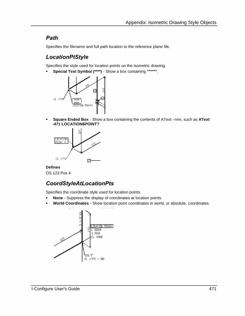
Appendix: Isometric Drawing Style Objects
I-Configure User's Guide 471
Path
Specifies the filename and full path location to the reference plane file.
LocationPtStyle
Specifies the style used for location points on the isometric drawing.
Special Text Symbol (****) - Show a box containing “****”.
Square Ended Box - Show a box containing the contents of AText –nnn, such as AText -471 LOCATION$POINT?
Defines
OS 123 Pos 4
CoordStyleAtLocationPts
Specifies the coordinate style used for location points.
None - Suppress the display of coordinates at location points.
World Coordinates - Show location point coordinates in world, or absolute, coordinates.

Appendix: Isometric Drawing Style Objects
472 I-Configure User's Guide
Relative Coordinates - Show location point coordinates in relative coordinates, with respect to the nearest reference plane.
Defines
OS 66 Pos 7
CoordStyle
Specifies the reference plane coordinate style.
World Coordinates - Show coordinates in world, or absolute, coordinates.
Relative Coordinates - Show coordinates in relative coordinates with respect to the nearest reference plane.
Defines
OS 66 Pos 7

Appendix: Isometric Drawing Style Objects
I-Configure User's Guide 473
Supplementary.RepeatFile Object Controls what data is to be repeated from an ISOGEN run.
Enabled (on page 473)
Path (on page 473)
ByPass (on page 473)
ComponentInfo (on page 473)
Content (on page 474)
MatList (on page 474)
SplitPoints (on page 474)
SpoolID (on page 474)
StartPoint (on page 475)
WeldNos (on page 475)
Enabled
Controls whether repeatability return file is created.
True - Create the repeatability return file.
False - Suppress creation of the repeatability return file.
Path
Specifies the filename and full path location to the repeatability return file.
ByPass
Controls whether by-pass component re-ordering is done.
True - Re-ordering of components at by-pass closure points to be done.
False - No re-ordering of components at by-pass closure points.
Defines
OS 109 Pos 6
ComponentInfo
Controls whether and how component information is written to the repeatability return file.
Off - Component information not to be written to the repeatability return file.
With Numeric - For numeric component information to be written to the repeatability return file.
With Alphabetic - For full alphanumeric component information to be written to the repeatability return file. (Maximum of 4 characters).
Defines
OS 109 Pos 5

Appendix: Isometric Drawing Style Objects
474 I-Configure User's Guide
Content
Controls the type of repeatability return file output.
Standard - Default for standard repeatability return file type (FOR052) containing just a list of successfully processed pipelines.
Original - For a repeatability repeatability return file containing the original repeat information.
Revised - For a repeatability return file containing the original repeat information and new records for spool information.
Original ASCII - ASCII version of Original.
Revised ASCII - ASCII version of Revised.
Defines
OS 109 Pos 1
MatList
Controls whether material list part number information is written to the repeatability return file.
True - Material list part number information to be written to the repeatability return file.
False - Material list part number information not to be written to the repeatability return file.
Defines
OS 109 Pos 8
SplitPoints
Controls whether split points are to be written to the repeatability return file.
True - Split point information to be written to the repeatability return file.
False - Split point information not to be written to the repeatability return file.
Defines
OS 109 Pos 3
SpoolID
Controls whether and how the SpoolID information is written to the repeatability return file.
Off - SpoolID information not to be written to the repeatability return file.
Numeric - SpoolID information to be written to the repeatability return file.
Alphabetic - For full alphanumeric SpoolID information to be written to the repeatability return file. (Maximum of 4 characters).
Defines
OS 109 Pos 4

Appendix: Isometric Drawing Style Objects
I-Configure User's Guide 475
StartPoint
Controls whether the start point for data extraction is written to the repeatability return file.
True - Data extraction start point to be written to the repeatability return file.
False - Data extraction start point not to be written to the repeatability return file.
Defines
OS 109 Pos 2
WeldNos
Controls whether Weld number information is written to the repeatability return file.
True - Weld number information to be written to the repeatability return file.
False - Weld number information not to be written to the repeatability return file.
Defines
OS 109 Pos 7
Supplementary.ReportFiles Object The Supplementary.ReportFiles object contains a collection called ISOGENFiles, which is used to store the names of output files that ISOGEN can create and the file path to be used for the particular file. For more information, see Supplementary.ReportFiles ISOGENFiles Collection (on page 475).
Count (on page 475)
Count
Displays the number of data entries stored in the Supplementary.ReportFiles ISOGENFiles collection (on page 475) collection.
Supplementary.ReportFiles ISOGENFiles Collection
Stores the output files, as well as their full path location, that ISOGEN creates during runtime.
System environment variables such as TEMP, USERNAME or COMPUTERNAME can be used in folder or file paths for report files.
FileType (on page 476)
FilePath (on page 476)
FileText (on page 477)

Appendix: Isometric Drawing Style Objects
476 I-Configure User's Guide
FileType
Double click the FileType list to select the type of output report file:
FilePath
Defines the file path.
73. Double-click the FilePath box.
74. In the Specify path for file dialog box, navigate to the appropriate file and then click OK.
Set the actual filename required. The filename itself can be dynamic, using the Pipeline Reference, for example, as part of the filename.

Appendix: Isometric Drawing Style Objects
I-Configure User's Guide 477
FileText
75. Double-click the FileText box.
76. In the text editor that displays, edit the data as necessary.
77. Click File > Update to save your changes.
To close the text editor without saving your changes, click File > Cancel.
Supplementary.SiteWeldFile Object Specifies information about the site weld file.
The Supplementary.SiteWeldFile object also contains a collection of options that define the columns for the site weld file. For more information, see Supplementary.SiteWeldFile TextColumns Collection (on page 478).
Enabled (on page 477)
Path (on page 477)
FileFormat (on page 477)
Delimiter (on page 478)
HeaderLines (on page 478)
Count (on page 478)
TitleText (on page 478)
ShowTitles (on page 478)
Enabled
Controls whether site weld file is created.
True - Create the file.
False - Suppress creation of the file.
Path
Provides the path to the site weld file. Type the full path and filename of the file.
FileFormat
Sets the format of the site weld file.
Fixed - Output a fixed format file.
Delimited - Output a delimited file.

Appendix: Isometric Drawing Style Objects
478 I-Configure User's Guide
Delimiter
Specifies a delimiter to use for the header lines that appear at the top of a SiteWeldInfo file. The possible characters are
Blank
Comma (,)
Semi-colon (;)
Colon (:)
HeaderLines
Specifies the text string for the column header.
\ - Start a new line.
| - Produce a vertical break.
You must make sure the column headers match the column positions set in the Material List Definition (MLD) file.
TitleText
Specifies text for the title.
ShowTitles
Specifies whether the title line is shown.
True - Display the title line.
False - Suppress the display of the title line.
Count
Displays the number of data entries stored in the Supplementary.SiteWeldFile TextColumns collection (on page 478).
Supplementary.SiteWeldFile TextColumns Collection
Specifies the columns for the site weld file.
The value that displays in parentheses after the collection name is a count of how many definitions are stored in the collection.
AttributeName (on page 478)
Justification (on page 479)
Start (on page 479)
MaxChars (on page 479)
See Also Add an Item to a Collection (on page 171) Remove an Item from a Collection (on page 172)
AttributeName
Specifies a property to appear in the column. Use the AttributeName list to select the required attribute.

Appendix: Isometric Drawing Style Objects
I-Configure User's Guide 479
Justification
Defines the justification for the text. Specify either Left or Right.
Start
Specifies the starting point of the column. The valid range is 1-999.
MaxChars
Defines the maximum number of characters.
Comment
Outputs a text comment for any definition contained in the previous columns. If any text is entered in this field, it is output as a comment--preceded by a !--to the relevant data or summary report file.
In the example below, a text comment has been entered for the part number, nominal size, item code, and quantity attributes.
The next example illustrates how the text comment is output to the relevant file.

Appendix: Isometric Drawing Style Objects
480 I-Configure User's Guide
Supplementary.SpoolAttributes Object Defines the data required for the output of spool attributes data on the isometric and to summary report files, such as the spool information file.
The Supplementary.SpoolAttributes object also contains a collection of options that are used to control the assignment of enclosure styles to spool attributes used to plot them on the isometric. For more information, see Supplementary.SpoolAttributes SpoolAttEnclosure Collection (on page 480).
Enabled (on page 480)
Path (on page 480)
ReferenceIDLocation (on page 480)
Count (on page 480)
Enabled
Controls the creation of spool attributes.
True - Attributes are created.
False - Attributes are not created.
Path
Specifies the filename and full path location to the spool attribute file.
ReferenceIDLocation
Sets the spool record as the key to map spool attributes.
Value - Spool records for possible mapping to spool attribute file:
-28
-91
- 170 to -179
The following is an example of the typical input in the DDF file:
SPOOL-REFERENCE-LOCATION-DEFINITION
RECORD-ID -28
Count
Displays the number of SpoolAttEnclosure definitions defined.

Appendix: Isometric Drawing Style Objects
I-Configure User's Guide 481
Supplementary.SpoolAttributes SpoolAttEnclosure Collection
Controls the assignment of enclosure styles to spool attributes used to plot them on the isometric.
The value that displays in parentheses after the collection name is a count of how many definitions are stored in the collection.
AttributeName (on page 481)
EnclosureType (on page 481)
AttributeName
Specifies the name of the attribute being defined. Use the AttributeName list to select the required attribute.
EnclosureType
Specify the name of the enclosure type. Use the EnclosureType list to select the required description.
Supplementary.SpoolInformation Object Stores the definitions for the spool information file in the Columns collection.
The Supplementary.SpoolInformation object also contains the following collection of options that are used to store the definitions of the data to be output to the spool information file. For more information, see Supplementary.SpoolInformation TextColumns Collection (on page 483).
Enabled (on page 481)
Path (on page 481)
FileFormat (on page 481)
Delimiter (on page 482)
HeaderLines (on page 482)
Count (on page 482)
Append (on page 482)
TitleText (on page 482)
ShowTitles (on page 482)
Enabled
Controls whether the creation of the spool information file.
True - File is created.
False - File is not created.
Path
Specifies the filename and full path location to the spool information file.

Appendix: Isometric Drawing Style Objects
482 I-Configure User's Guide
FileFormat
Defines the format of the output file.
Fixed - Outputs a fixed format file.
Delimited - Output a delimited file.
Delimiter
Defines the character used as a delimiter when the file format is delimited. The possible characters are
Blank
Comma (,)
Semi-colon (;)
Colon (:)
HeaderLines
Specify the text string for the column header.
\ - Starts a new line.
| - Produces a vertical break.
You must ensure that the column headers match the column positions set in the data definition file (DDF).
Count
Displays the number of data entries stored in the Supplementary.SpoolInformation TextColumns collection (on page 483).
Append
Defines whether the file is opened in appended mode or overwrite mode.
True - Append the file.
False - Overwrite the file.
TitleText
Specifies text for the title.
ShowTitles
Specifies whether the title line is shown.
True - Display the title line.
False - Suppress the display of the title line.

Appendix: Isometric Drawing Style Objects
I-Configure User's Guide 483
Supplementary.SpoolInformation TextColumns Collection
Stores the definitions of the data to be output to the spool information file.
The value in parentheses after the name is a count of how many definitions are stored in the collection.
AttributeName (on page 483)
Justification (on page 483)
Start (on page 483)
MaxChars (on page 483)
Comment
See Also Add an Item to a Collection (on page 171) Remove an Item from a Collection (on page 172)
AttributeName
Specifies the name of the attribute being defined. Use the AttributeName list to select the required attribute.
Justification
Defines the justification for the text. Specify either Left or Right.
Start
Defines the start column for the output data on a fixed format file, and specifies a field number for a delimited file.
MaxChars
Defines the maximum number of characters.
Comment
Outputs a text comment for any definition contained in the previous columns. If any text is entered in this field, it is output as a comment--preceded by a !--to the relevant data or summary report file.
In the example below, a text comment has been entered for the part number, nominal size, item code, and quantity attributes.
The next example illustrates how the text comment is output to the relevant file.

Appendix: Isometric Drawing Style Objects
484 I-Configure User's Guide
Supplementary.TableAttributes Object The Supplementary.TableAttributes object contains a collection called DFTableAttributes, which is used to store the definitions of the data to be output as a table on the isometric drawing. For more information, see Supplementary.TableAttributes DFTableAttributes Collection (on page 484).
The existing Supplementary.TableAttributes object contains the same information as the DrawingFrame.TableAttributes object. You can use either object to modify the properties, although the DrawingFrame.TableAttributes object supports real numbers in the XPos and YPos properties.
Count (on page 484)
Count
Displays the number of definitions in the Supplementary.TableAttributes DFTableAttributes Collection (on page 484).
Supplementary.TableAttributes DFTableAttributes Collection
Stores the definitions of the data to be output as a table on the isometric.
AttributeName (on page 485)
CharHeight (on page 485)
Xpos (on page 485)
Ypos (on page 485)
Font (on page 485)
BarCode (on page 485)
CharWidth (on page 486)
Justification (on page 486)
Layer (on page 486)
Colour (on page 486)
RotationAngle (on page 486)
TextWeight (on page 486)
ColumnsNumber (on page 486)
Direction (on page 486)
LinesNumber (on page 487)
XSpacing (on page 487)
YSpacing (on page 487)

Appendix: Isometric Drawing Style Objects
I-Configure User's Guide 485
AttributeName
Specifies the name of the attribute being defined. Use the AttributeName list to select the required attribute.
CharHeight
Sets the character height for the text. Type the required size in mm or inches (as a real number), depending on the setting of the drawing units in the Options dialog box.
See Also
Options (on page 36)
Xpos
Defines the X position for the text in mm or inches (set as real number), depending on the setting of the drawing units in the Options dialog box.
See Also
Options (on page 36)
Ypos
Defines the X position for the text in mm or inches (set as real number), depending on the setting of the drawing units in the Options dialog box.
See Also Options (on page 36)
Font
Defines the font to be used when plotting the attribute in the table.
BarCode
Several barcode standards exist worldwide to suit different industries, but Alias has standardized on just three. Type 1, 2 or 3 for the appropriate barcode:
1 - Barcode 39
2 - Barcode 25
3 - Barcode 25 Interleaved

Appendix: Isometric Drawing Style Objects
486 I-Configure User's Guide
CharWidth
Sets the character height for the text. Type the required size in mm or inches (as a real number), depending on the setting of the drawing units in the Options dialog box.
See Also Options (on page 36)
Justification
Defines the justification for the text. Specify either Left or Right.
Layer
Specify the integer number that identifies the required layer (in the Drawing.Layers Layers collection (on page 289)) to which the definition is applied.
Colour
Type the integer number that represent the colour number as defined in the output drawing system (MicroStation or AutoCAD).
RotationAngle
Defines the angle of rotation in degrees clockwise.
TextWeight
Controls the character thickness. Type a value between 1 and 9. Used for MicroStation only
TruncationLength
Defines the number of output characters.
ColumnsNumber
Specifies the number of columns in the table.
Direction
Specifies the table direction.

Appendix: Isometric Drawing Style Objects
I-Configure User's Guide 487
LinesNumber
Specifies the number of lines in the table.
XSpacing
Specifies the table offset dimension in X (horizontal) direction. Type a value in mm or inches (set as a real number), depending on the setting of the drawing units in the Options dialog box. For example, you can type 50mm or 2.0 inch.
The value can be a negative number.
See Also Options (on page 36)
YSpacing
Specifies the table offset dimension in Y (vertical) direction. Type a value in mm or inches (set as a real number)<SPIConfigStart, depending on the setting of the drawing units in the Options dialog box. For example, you can type 50mm or 2.0 inch.
The value can be a negative number.
See Also Options (on page 36)
Supplementary.TitleTexts Object Specifies user-defined text strings for plotting on an ISOGEN-generated drawing frame. The Supplementary.TitleTexts object also contains a collection called TitleTexts. For more information, see Supplementary.TitleTexts TitleTexts Collection (on page 487).
Count (on page 487)
Count
Displays the number of definitions in the Supplementary.TitleTexts TitleTexts collection (on page 487).
Supplementary.TitleTexts TitleTexts Collection
The definitions in the Supplementary.TitleTexts TitleTexts collection each store one line of text to be used for the titles.
TText (on page 488)
See Also Add an Item to a Collection (on page 171) Remove an Item from a Collection (on page 172)

Appendix: Isometric Drawing Style Objects
488 I-Configure User's Guide
TText
Contains the text for each title line.
Supplementary.Traceability Object Defines a unique part numbers table that can be output on the isometric drawing and a traceability output file.
The Supplementary.Traceability object also contains a collection of options that define the data output to the traceability file. For more information, see Supplementary.Traceability TextColumns Collection (on page 491).
Enabled (on page 488)
Path (on page 488)
UniquePartNumber (on page 489)
IdentifierSuffix (on page 489)
PlotUniquePtNoTable (on page 489)
ContinuousDown (on page 489)
StartX (on page 489)
StartY (on page 489)
VerticalSpacing (on page 490)
TextHeight (on page 490)
MaxEntries (on page 490)
TableOverflow (on page 490)
DrawingLayer (on page 490)
UniqueNosBolts (on page 491)
UniqueNosGaskets (on page 491)
Count (on page 490)
Enabled
Controls the creation of the traceability file.
True - File is created.
False - File is not created.
Path
Defines the output path of the traceability file.

Appendix: Isometric Drawing Style Objects
I-Configure User's Guide 489
UniquePartNumber
Controls the type of suffix used for the unique part number and whether unique part numbers are used.
Alpha - Use an alphabetic suffix.
Numeric - Use a numeric suffix.
Off - Switch off all unique part number facilities.
IdentifierSuffix
Controls sequencing of the IdentifierSuffix used for part numbering on the isometric.
Continuous - Generate unique part number suffixes as a continuous sequence across all output drawings, such as 6.1 to 6.6 on Drg 1 of 2 and 6.7 to 6.11 on Drg 2 of 2, and so on.
PerDrawing - Generate unique part number suffixes with a new sequence for each drawing, such as 6.1 to 6.6 on Drg 1 of 2 and 6.1 to 6.5 on Drg 2 of 2, and so on.
PlotUniquePtNoTable
Controls whether the unique part numbers table is plotted.
True - Plot the table.
False - Suppress plotting of the table.
ContinuousDown
Controls the direction of the unique part numbers table.
True - Table direction is down.
False - Table direction is up.
StartX
Defines the starting X position of the list in mm, or inches (as a real number), depending on the setting of the drawing units set on the Options dialog box.
See Also Options (on page 36)
StartY
Defines the starting Y position of the list in mm, or inches (as a real number), depending on the setting of the drawing units set on the Options dialog box.
See Also Options (on page 36)

Appendix: Isometric Drawing Style Objects
490 I-Configure User's Guide
VerticalSpacing
Sets the vertical spacing between each horizontal line in mm or inches (as a real number), depending on the setting of the drawing units set on the Options dialog box.
See Also Options (on page 36)
TextHeight
Sets the text height to be used. Type a value (real number) in mm or inches, depending on the setting of the drawing units set on the Options dialog box.
See Also
Options (on page 36)
MaxEntries
Controls the maximum number of entries before an overflow drawing is created if the TableOverflow property is set to True.
See Also TableOverflow (on page 490)
TableOverflow
Controls whether an overflow drawing is created when MaxEntries is exceeded.
True - Create an overflow drawing.
False - Suppress creation of an overflow drawing.
See Also MaxEntries (on page 490)
DrawingLayer
Sets the drawing layer for unique part number table. Type a value in the range of 1 to 50.
Count
Displays the number of definitions in the Supplementary.Traceability TextColumns collection (on page 491).

Appendix: Isometric Drawing Style Objects
I-Configure User's Guide 491
UniqueNosBolts
Controls output of unique part numbers on bolts.
Yes - Output unique part numbers on bolts.
No - Suppress output of unique part numbers on bolts.
UniqueNosGaskets
Controls output of unique part numbers on gaskets.
Yes - Output unique part numbers on gaskets.
No - Suppress output of unique part numbers on gaskets.
Supplementary.Traceability TextColumns Collection
Stores the definitions of data for the output of unique part numbers.
The value in parentheses after the name is a count of how many definitions are stored in the collection.
AttributeName (on page 491)
Justification (on page 491)
Start (on page 491)
MaxChars (on page 492)
Comment (on page 492)
See Also Add an Item to a Collection (on page 171) Remove an Item from a Collection (on page 172)
AttributeName
Specifies the name of the attribute being defined. Use the AttributeName list to select the required attribute.
Justification
Defines the justification for the text. Specify either Left or Right.
Start
Defines the start column for the output data on a fixed format file, and specifies a field number for a delimited file.

Appendix: Isometric Drawing Style Objects
492 I-Configure User's Guide
MaxChars
Defines the maximum number of characters.
Comment
Outputs a text comment for any definition contained in the previous columns. If any text is entered in this field, it is output as a comment--preceded by a !--to the relevant data or summary report file.
Supplementary.PrintedMaterialList Object Defines the header content of the printed material list.
Enabled (on page 492)
Path (on page 492)
FileFormat (on page 492)
Delimiter (on page 492)
TitleText (on page 493)
ShowTitles (on page 493)
Enabled
Controls creation of the printed material list.
True - Create the printed material list.
False - Suppress creation of the printed material list.
Path
Specifies the filename and full path location to the printed material list.
FileFormat
Defines the format of the printed material list.
Fixed - Output the printed material list in a fixed format.
Delimited - Output the printed material list in a delimited format.
Delimiter
Specifies a delimiter to use for the header lines that appear at the top of a printed material list. The possible characters are
Blank
Comma (,)
Semi-colon (;)
Colon (:)

Appendix: Isometric Drawing Style Objects
I-Configure User's Guide 493
TitleText
Specifies text for the title.
ShowTitles
Specifies whether the title line is shown.
True - Display the title line.
False - Suppress the display of the title line.

Appendix: Isometric Drawing Style Objects
494 I-Configure User's Guide

I-Configure User's Guide 495
A P P E N D I X B
Alternative Text, or AText has it is often called, is a powerful ISOGEN feature that enables any text on the isometric drawing to be easily changed or removed.
The feature operates by assigning a unique identification number to each standard text string. The ID number is then referred to whenever a change is required to the text string that the number represents.
For a complete list of available ATexts and their default values, see Grouping of AText Listings (on page 497).
By definition, a standard text string can be a single character, a single word, or a group of words. However, some ATexts are, by default, set to an all blank word. The total number of separate standard text strings held by the software in this way is in excess of 300.
Identification Number Format
Because identification numbers are always negative, they are must be preceded by a minus sign. For example, AText -249 represents the default word WEST, which is used in the main isometric drawing area.
See Also Specify Alternative Texts (on page 523) Using Alternative Text (on page 495)
Using Alternative Text AText allows you to substitute your own text terminology or language in place of the standard ISOGEN words on the isometric. To make a word change, you do not have to replace the entire standard AText--you can change as little as just one word if that is all is required.
Although the AText feature has a considerable degree of built-in flexibility, you must exercise a certain amount of care when defining your own words, particularly in terms of word lengths. As a general rule, newly defined words or word strings should be about equal in length or shorter than the text that is being replaced. Obvious exceptions to this are the cases of the single line headings in the material list region. In this respect, you must take full responsibility for word definition. ISOGEN does not warn you in cases where words are too long and cannot be accommodated in the standard space provided on the isometric. Badly designed AText can lead to undesirable results, such as over-writing or incorrectly positioned text.
Special Characters
The following special characters further extend the functionality of ATexts:
The Dollar ($) Sign - The $ character, which is used in ISOGEN to force a new line in regular isometric message text, can also be used with ATexts. However, when using the $ character, it is recommended that you carefully check the output results of each occurrence.
Appendix: Alternative Text

Appendix: Alternative Text
496 I-Configure User's Guide
The Question Mark (?) - The ? character has the following two different uses:
In ATexts -210, -211 and -212 to suppress the plotting of the single characters normally associated with these ATexts, without switching off their associated facility, as would normally happen when an AText is set to blank. For example, setting AText -210 ? suppresses the F that is normally plotted. It does not completely suppress the plotting of the flange material list part number as would normally happen when an AText item is set to blank. Using the ? character is particularly advantageous on spool isometrics.
In some special ATexts at points where the software dynamically inserts information. By default, AText -456 is set to DETAIL ?. As a result, the software inserts either a letter or a number, depending upon which system you have specified at the position of the ? character.
The "At" (@) Sign - You can use the @ character to pad out an AText string with trailing blanks. As a result, the text that follows the AText has a series blanks between it and the AText.
Foreign Language Use
AText is particularly beneficial to foreign language users who want to produce isometrics containing text in their native language. However, there are restrictions governing which characters are permissible. Those restrictions are outlined in The Usable Character Set.
The Usable Character Set
You can only use the following standard English and special purpose characters in AText definitions:
Upper- or lower-case letters in the range A to Z.
Numeric characters in the range 0 to 9 inclusive.
A blank space character.
The following special purpose symbols: * + - . , : [ ] ( ) # ' < > = | & %
Other foreign language characters, such as those used in the Cyrillic, Greek, or Chinese alphabets are excluded, as are specially accentuated characters, such as à, á, â, and so on.
AText and the Drawing Frame Symbols
The AText feature goes further than just controlling text characters. The standard symbols appearing in the line summary area across the bottom of the standard ISOGEN drawing frame, viz. for shop weld, field weld, and so on through traced pipe, can all be suppressed when they are not required by setting their associated ATexts to blank.
Composite Text Messages
Composite text messages are made up of more than one text item and the composition is done by ISOGEN automatically. Such messages can be composed in either of the following two ways:-
By combining two or more related ATexts
By combining AText and an associated design database attribute value
Generally, in those cases where AText operates together with design database attribute information to form a composite message, setting the AText part to blank to suppress the plotting of it causes suppression of the attribute text also. For example, if the composite message BATCH REF: 12/100A/C in the title block area needs to be completely suppressed, then setting AText -252, which contains the words BATCH REF, to blank causes both this and the attribute part, 12/100A/C, not to be plotted.

Appendix: Alternative Text
I-Configure User's Guide 497
Examples The following are some examples of standard ATexts:
The material list heading ERECTION MATERIALS.
The isometric connection messages CONN. TO and CONT. ON in the main drawing area.
The BATCH REF and PIPING SPEC headings in the title block area.
Each of these are default AText words that are programmed in by ISOGEN but which you can re-program, if required, as explained in the following examples.
Example 1: ERECTION MATERIALS
You can find ERECTION MATERIALS as AText -310 (see "Plotted Material and Cut Pipe List Heading Texts" on page 506). To change the default heading (ERECTION MATERIALS) to CONSTRUCTION MATERIALS, the entry - 310 CONSTRUCTION MATERIALS must appear in the appropriate data input file.
Example 2: CONN.TO
CONN TO. is an example of a composite message that is used at locations where pipelines are connected to equipment nozzles. You can find it as AText -208.
To change the message CONN. TO to JOIN TO, the entry -208 JOIN TO must appear in the appropriate data input file. Information regarding the joined to component, that is, the nozzle name as extracted from the design database, is automatically appended to the AText by ISOGEN to form a composite message, such as JOIN TO D45-NZ12.
Example 3: BATCH REF
BATCH REF is another composite message example--AText -252 (see "Title Block/Drawing Frame" on page 513). The message is used to convey plant zone or area information in the title block area of the isometric where the contents of the BATCH (AREA) type record in the pipeline input data file is automatically appended by ISOGEN. An example of this kind of message is BATCH REF : AR-A/TF/N12.
To remove the batch reference entry from the isometric, set the AText entry in the input data file (IDF) to blank, thus: -252
Doing so removes the entire composite message from the isometric, both the AText BATCH REF : part and the following design database attribute that holds the batch reference information.

Appendix: Alternative Text
498 I-Configure User's Guide
Grouping of AText Listings All the AText listings are logically grouped into the following isometric drawing regions:
Isometric Drawing Area (on page 498)
Plotted Material and Cut Pipe List Heading Texts (on page 506)
Specification Change Indication (on page 513)
Title Block/Drawing Frame (on page 513)
Line Summary Area (on page 515)
Printed Material List (on page 516)
Weld Box Summary (on page 516)
Flat Spools and Flange Rotation (on page 518)
Compipe Material Control Links (on page 519)
SPOOLGEN (FFISYS) Screen Display (on page 519)
Reference Plane System (on page 523)
Isometric Drawing Area
-201 E Denotes East at east coordinates.
-202 N Denotes North at north coordinates.
-203 W Denotes West at west coordinates.
-204 S Denotes South at south coordinates.
-205 EL + Denotes a positive Elevation at elevation coordinates.
-206 EL - Denotes a negative Elevation at elevation coordinates.
-207 ? NS Denotes the pipe nominal size. By setting the AText to blank, the nominal size message is suppressed. Using a ? symbol determines the format used for outputting the nominal size message.
-208 CONN. TO Denotes CONNected TO, where a pipeline/branch end is connected to a nozzle.
-209 CONT. ON Denotes CONTinued ON at the point, where a pipeline/branch end is continued onto another pipeline. Used in conjunction with END-CONNECTION type record. Is also used with AText -255 to create a CONT. ON DRG 2 type message when a pipeline is split into multiple drawings. (Isometric drawing area and Material List overflow).
-210 F Denotes flange--the letter used with the material list cross-reference pointer for flanges.
-211 G Denotes gaskets--the letter used with the material list cross-reference pointer for gaskets.
-212 B Denotes bolts--the letter used with the material list cross-reference pointer for bolts.
-213 SPINDLE Indicates the direction of an operating spindle on a valve when it is not pointing in a primary direction.

Appendix: Alternative Text
I-Configure User's Guide 499
-214 MM Denotes millimetres. Used with arrowed dimensions on angle and multi-way valves to indicate leg length.
-215 REDUCING FLANGE
Denotes a reducing flange. The indicator points to the location of the reducing flange.
-216 OFFSET Indicates a dimensional offset, such as eccentric reducer, offset reducing flange, all forms of offset blocks.
You can use a ? symbol to determine format used for outputting the offset messages. By setting this AText to blank, the offset message is suppressed.
-217 MITRE Denotes mitered bends. (It is used in conjunction with AText -231 BEND).
-218 LOBSTER Indicates lobster back bends. (It is used in conjunction with AText -231'BEND).
-219 REINFORCED Plots an identification message that points to a reinforced tee or cross when the symbol key is TERF or CRRF and no reinforcement pad component is called for.
-220 LEFT LOOSE Plots a distinguishing message that points to a flange where the LOOSE indicator is set.
-221 FFW Plots a distinguishing message that points to a field fit weld.
-222 FALL Denotes a FALLing line. Used in conjunction with the Fall symbol. You can use a ? symbol to determine the format used for outputting the falling line messages. By setting this AText to blank, the falling line message is now suppressed, but the fall indication symbol is still ,shown.
-223 (Normally blank) Produces a software-generated degree (°) symbol, which is output at all angle indicators requiring a degree symbol (bends, falls, and so on).
-224 : This symbol is used for falling lines specified with a ratio, such as 1:10.
-225 (Normally blank) Produces a system-generated percent (%)symbol used on falling pipelines specified with a percentage indication
-226 GRAD Indicates a falling line specified in gradients.
-227 PER M Indicates a falling line specified as an incline in Metric units, such as millimetres per metre.
-228 PER FT Indicates a falling line that is specified as an incline in Imperial units, such as inches per foot.
-229 SCREWED END Plots an indicator that points to a pipe end that has been set to screwed in the pipeline input data file.
-230 VENT Plots an indicator that points to a vent position at any open ended pipe. It is used in conjunction with an END-POSITION-VENT type record.
-231 BEND Identifies miter and lobster back type bends. Used in conjunction with AText -217 and AText -218.

Appendix: Alternative Text
500 I-Configure User's Guide
-232 SPEC Plots an identification message points to any place in the pipe where the piping specification changes. The name of the new specification is automatically indicated.
-233 C Identifies a connector as part of a material list cross-reference, such as C13 in a box.
-234 (Normally blank) Prefixes liners and nut material part numbers that are output on the isometric drawing. Clamps use AText -233 to prefix their part number.
-235 (default) Plots a user-defined start point message on the isometric drawing. Use the special characters listed below to output other items of information as part of the message:
$ - Split message over several lines.
? - Output the system/pipeline reference (IDF record -25 or -6)
?? - Output the spool reference (IDF record -7 or -28)
#nnn - Output the pipeline attribute. Where nnn is set to 0 to 99, outputs ATTRIBUTES0 to ATTRIBUTES99 (IDF records -600 to -699). Where nnn is set to 100 to 199, outputs ATTRIBUTES100 to ATTRIBUTE199 (IDF records -900 to -990)
-236 S Identifies a support as part of a material list cross-reference, such as S22 in a box.
-237 " Denotes the inch sign indicator is used in Imperial dimensions coordinates and nominal size outputs.
-238 ' Denotes the feet sign indicator used in imperial dimensions and coordinates.
-239 DRAIN Plots a message that points to a drain position any open-ended pipe. It is used in conjunction with an END-POSITION-DRAIN type record
-240 (Normally blank) This AText is blank by default but can be used to produce a message at any open-ended pipe. It is used in conjunction with an END-POSITION-OPEN type record.
-241 (Normally blank) This AText is blank by default but can be used to produce a message at any closed- ended pipe. It is used in conjunction with an END-POSITION-CLOSED type record.
-242 (Normally blank) This AText is blank by default but can be used to produce a message at any miscellaneous pipe end. It is used in conjunction with an END-POSITION-NULL type record.
-243 (Normally blank) This AText has no default text, but if you set it to a word, such as FLAT, then that text acts as a trigger to output the flat direction of eccentric reducers that have their flat side pointing in a primary direction. (Is used in conjunction with ATexts -244 to -249 inclusive).

Appendix: Alternative Text
I-Configure User's Guide 501
The following six ATexts (-244, -245, -246, -247, -248, and -249) are used to output directions in conjunction with other ATexts on items that carry a direction setting on the component record in the pipeline input data file.
-244 UP Appends a primary direction as part of a composite message. Used in conjunction with ATexts -243, -278, -280, -281 and -282.
-245 DOWN Appends a primary direction as part of a composite message. Used in conjunction with ATexts -243, -278, -280, -281 and -282.
-246 NORTH Appends a primary direction as part of a composite message. Used in conjunction with ATexts -243, -278, -280, -281 and -282.
-247 SOUTH Appends a primary direction as part of a composite message. Used in conjunction with ATexts -243, -278, -280, -281 and -282.
-248 EAST Appends a primary direction as part of a composite message. Used in conjunction with ATexts -243, -278, -280, -281 and -282.
-249 WEST Appends a primary direction as part of a composite message. Used in conjunction with ATexts -243, -278, -280, -281 and -282.
-275 SWEPT TEE Plots a message that points to a tee whose symbol key starts with the characters TS.
-276 CONT. FROM Denotes CONTinued FROM. This message is plotted when a pipeline is split onto two or more drawings, such as CONT. FROM DRG 1. (The text DRG comes from AText -255. For more information about this AText, see Title Block/Drawing Frame (on page 513).
-277 ORIFICE FLANGE Outputs text that points to orifice flanges.
-278 DIAL FACE Outputs text that points to instruments dials whose symbol key starts with the characters ID and is followed by a relevant direction letter. See the following Notes for more information.
-279 L Denotes lap joint stub end the letter used with the material list cross-reference pointer for LJSE's.
-280 TAPPING Outputs text that points to orifice plates and is followed by a relevant direction letter. See the following Notes for more information.
-281 TAIL Outputs text that points to spectacle blinds and slip plates and is followed a by relevant direction letter. See the following Notes for more information.
-282 WINDOW Outputs text that points to a site glass and is followed by a relevant direction letter. See the following Notes for more information.
-283 FLAT Identifies non-primary flat directions on eccentric reducers. The contents of this AText is output in front of the contents of a DIRECTION record containing the flat skew direction
AText Numbers -243, -278, -280, -281 and -282 are only output if a primary direction is set in the component record in the pipeline input data file.

Appendix: Alternative Text
502 I-Configure User's Guide
The appropriate direction (as defined by ATexts -244 to -249) is appended to the specific fitting text to make a composite message--such as DIAL FACE WEST. Alternatively, the content of any DIRECTION (Compound Directions) record can be appended.
-284 TEE BEND Plots text at bends that have an off-line leg.
-285 RATING FLANGE Provides an extra message at a flange that has a different pressure rating to standard. This is achieved by giving the mating gasket a symbol key of the required rating (such as. 300#) in the Intermediate Data File (IDF). The facility is only used on fixed length piping.
-286 (Normally blank) This AText is blank by default but if set it will output the text as a message on screwed erection (construction) fittings.
-287 ORIENTATION DIRECTION
Identifies the direction of skewed branches in cases where skew box indication has been suppressed. A program generated direction will be appended to this text to form a complete message.
-288 PIPE Denotes the position(s) of a change in the pipeline reference on system isometrics
-298 TEE ELBOW Identifies a tee elbow fitting.
-337 D BEND RADIUS Outputs the text D bend radius on individual pulled bends where the bend radius is expressed in terms of a number of pipe diameters. The bend radius value is extracted from a BEND-RADIUS type record in the pipeline input data file and used as a prefix to this AText.
-338 BEND RADIUS Outputs the text bend radius on individual pulled bends where the bend radius is expressed in terms of the dimensional units in use. The bend radius value is extracted from a BEND-RADIUS type record in the pipeline input data file and used as a prefix to this AText.
-346 GEARBOX ORIENTATION
Is used in conjunction with directional information taken from a GEARBOX type record in the pipeline input data file and which is appended to this AText.
-349 PP Indicates personal protection type insulation on insulation Indication symbols having the symbol key 'NPP.
-350 REDUCING ELBOW Indicates a reducing elbow on fittings having the symbol key ER**.
-356 U Identifies special type pulled bends. Is used both on the isometric area and on the material list.
-357 B Identifies special type erection welds. Is used both on the isometric area and on the material list.
-358 W Identifies special type fabrication welds. Is used both on the isometric area and on the material list.
-362 END$ONE Identifies a specific end on a spool isometric.Used in special circumstances. It also appears in the cut pipe list section for use as a column heading on the cut pipe list.

Appendix: Alternative Text
I-Configure User's Guide 503
-388 TANGENTIAL CONNECTION
Identifies tangential / offset connections. In cases where the tapping point method is used, the existing TAPPING CONNECTION (AText No. -451) message will not be output.
-389 OFFSET CONNECTION
Identifies tangential / offset connections. In cases where the tapping point method is used, the existing TAPPING CONNECTION (AText No. -451) message is not output.
-390 FROM ? ORIGIN Identifies tangential / offset connections. In cases where the tapping point method is used, the existing TAPPING CONNECTION (AText No. -451) message is not output.
-391 (Normally Blank) Identifies tangential / offset connections. In cases where the tapping point method is used, the existing TAPPING CONNECTION (AText No. -451) message is not output.
-392 MULTIPLE Indicates that multiple components attributes are present for a particular material entry.
-394 TOT Distinguishes an accumulated pipe sub-total from an individual pipe entry.
-395 ? Outputs a modified heat tracing component part number. Default is ?.
-396 ? INC ANGLE Default is blank. If OS 67 set to 1 and this AText set ? character is substituted by angle value and combined with INC ANGLE text to indicate that angles displayed for elbows and bends on isometric are included (not deflected) angles.
-399 N or U Labels the viewpoint direction arrow. N denotes north and U denotes up. The default label for combined, fabrication, erection and normal spool isometrics is N, while U is the default label for flat spool isometrics. If set to Blank, the viewpoint direction arrow is suppressed.
-425 SEAL WELD Indicates the weld type for seal welds on the isometric drawing.
-433 (Normally blank) Plots a message that points to a user-positioned set on connections.
-434 STUB IN Plots a message that points to a user-positioned set in connections.
-243 (Normally blank) This AText has no default text but if it is set to a word (such as FLAT) by the user then that text acts as a trigger to output the flat direction of eccentric reducers that have their flat side pointing in a primary direction. (Is used in conjunction with ATexts -244 to -249 inclusive).
-437 (Normally blank) Allows metric dimensions to have their dimensional units output on the isometric drawing.
-439 (EOP) Shows edge of pipe dimensions.
-440 NOZZLE? Indicates the nozzle names attached to items of equipment.
-441 EQUIPMENT$LOCATION
Indicates equipment location.

Appendix: Alternative Text
504 I-Configure User's Guide
-451 TAPPING CONNECTION
Is output along with coordinate values at the tapping point on a user-defined fitting. Requires Option Switch 122 to be set to 1 for tapping coordinates output on the isometric drawing.
-452 UNACCEPTABLE SPLIT
Indicates that an unacceptable drawing split point has been found in tube. When used, the message is output in the top left-hand corner of each affected drawing.
-454 CONNECTION ORIENTATION
Indicates undeveloped set-on tees and olets, which have no branch leg and are indicated in dotted form on the pipeline, where the intended branch connection is in a skewed direction. A system-generated direction word is appended to this text to form a composite message.
-455 (Normally blank) Indicates the elevation coordinate of the flange connection face. Used at flange positions in vertical pipe legs. The special characters ? and $ can be combined with this AText to allow you to control the final form of the output text. ? is used to cause the insertion of elevation value, and $ forces a new line of text. For example, a setting of ?$FLANGE FACE produces EL +22613 FLANGE FACE. In this situation, the EL characters are obtained by the software also using AText -205 automatically.
-456 SEE DETAIL ? Provides a cross-reference message for detail sketches. This AText appears on the drawing part of the isometric. The sketch identifying number or letter is edited in by the software at the ? position.
-457 MITRE ? Identifies miter welds. The software edits in the miter angle into the text string at the ? position which can be positioned anywhere in the string.
-458 (Normally Blank) Indicates the nominal size for metric bore units. For example, if set to mm the output is 32mm NS; if set to Blank, then 32NS is output.
-459 ?THK Shows thickness of a penetration plate on the drawing.
-469 REFERENCE POINT Identifies a reference dimension Item coordinates.
-470 SUPPORT LOCATION
Identifies pipe support coordinates.
-477 CUT OUT ? Shows the location of where material should be removed.
-479 PORT REF Displays a reference message at each port on the isometric drawing. If set to Blank, the message is suppressed.
-480 PORT CO-ORDS Displays coordinate information at each port on the isometric drawing. If set to Blank, the display of coordinate data output is suppressed.
The following nine ATexts are all used for the identification of external reference Items when using the reference dimension facility. Any associated text elements will be automatically pre-fixed or appended, as appropriate, to the specified AText element.
In all these ATexts, the $ character causes a new line to be plotted, and a ? character is where the software edits in the element name (from any -37, 70, 71 or 72 type record) to derive the full text string.

Appendix: Alternative Text
I-Configure User's Guide 505
-460 BEAM$? Identifies horizontal steel-work element (SKEY HST*).
-461 COLUMN$? Identifies vertical steel-work element (SKEY VST*).
-462 ?$BUILDING CL Identifies centreline of building (SKEY BLD*).
-463 CL EQUIPMENT$? Identifies centreline of equipment (SKEY EQU*).
-464 CL PIPELINE$? Identifies centreline of pipeline (SKEY PIP*).
-465 ?$FLOOR LEVEL Identifies specified floor level (SKEY FLR*).
-466 ?$WALL Identifies specified wall position (SKEY WAL*).
-467 GRID LINE$? Identifies project grid line (SKEY GRD*).
-468 ? Used for miscellaneous user-defined elements (SKEY XXX*). The default ? character causes any identification name associated with the miscellaneous reference to be used when no other AText setting is made.
-471 LOCATION-POINT? Indicates a location point position on the plotted isometric. If more than one is included on any single isometric, a simple ID number is generated and output in the position indicated by the ?.
-475 (Normally blank) Indicates the position of any location points that are included in an incoming pipeline data file. Used in the SmartPlant Spoolgen Probing module. Value must be defined.
-476 (Normally blank) Trigger the indication of drawing identifiers. Used in SmartPlant Spoolgen.
-498 (Normally blank) Points to a site weld. Value must be defined.
-499 SHOP TEST WELD Points to either a site weld or a field fit weld that requires a shop test weld to be performed at the same location. (That is welds with the key WSST or WFST).
-501 (Normally blank) Points to an offshore weld if user-defined.
-502 SUPPORT Indicates the orientation of a pipe support. Content of associated DIRECTION record (containing compound directions for skewed support) is appended to AText.
-512 TACK WELD Plots a distinguishing message that points to a user-positioned tack weld.
-533 FI Identifies field Items on an erection type isometric whenever a new style operations box is requested ( Option Switch 53 Position 2 set to 2).
-534 RL Identifies a random length on an erection type isometric whenever a new style operations box is requested ( Option Switch. 53 Position 2 set to 2).
-535 SU Identifies a pipe support on an erection type isometric whenever a new style operations box is requested ( Option Switch. 53 Position 2 set to 2).

Appendix: Alternative Text
506 I-Configure User's Guide
-536 VL Identifies a valve on an erection type isometric whenever a new style operations box is requested ( Option Switch 53 Position 2 set to 2).
-539 . Used as a delimiter between the material list cross-reference identifier and the suffix that is added as a unique component identifier in the new style of Identifier ( 3.1, 3.2, 3.3 as opposed to 3).
-541 _N Used as delimiter/identifier in general note names.
-542 _S Used as delimiter/identifier in general note names.
-543 (Normally blank) Indicates the position of any special note names that are included in an incoming pipeline data file. Used in SmartPlant Spoolgen Probing module.
-544 (Normally blank) Indicates the position of any additional materials that are included in an incoming pipeline data file. Used in SmartPlant Spoolgen probing module.
-545 / Used as a separator between part numbers when outputting dual numbers for associated additional material identification on the plotted isometric.
-546 I (Default) Used as the first character of the drawing output file extension (used in conjunction with Option Switch 71 Pos. 7).
-547 _ (Default) Underline character.
-548 HOR ? Distinguishes horizontal skew angles from vertical skew angles on isometric drawings.
-549 ? VER Distinguishes vertical skew angles from horizontal skew angles on isometric drawings.
-550 (Normally Blank) Outputs a nominal size message on reducing tees, such as TEE RED.
-551 (Normally Blank) Outputs a nominal size message on equal tees, such as TEE EQU.
-552 (Normally Blank) Outputs a nominal size message on concentric reducers, such as CONC RED.
-553 (Normally Blank) Outputs a nominal size message on eccentric reducers, such as ECC RED.
-885 - FFISYS AText for FF isometric continuation message delimiter.

Appendix: Alternative Text
I-Configure User's Guide 507
Plotted Material and Cut Pipe List Heading Texts
-274 (Normally blank) If set, is used as a separator between the pipeline reference and the spool identifier in the spool isometric drawing identifier.
-300 FABRICATION MATERIALS Is the category heading under which components required for SHOP Fabrication are listed.
-301 PT Is the part number heading used in conjunction with AText -302 to form a composite message.
-302 NO Used in conjunction with AText -301 to form a composite message.
-303 COMPONENT DESCRIPTION Is the heading in the material listing under which components are described according to their catalog component description.
-304 N.S. Is the heading under which the nominal size of each item is listed. Is used in conjunction with AText -330 or AText -331 to form a composite message.
-305 ITEM CODE Is the heading under which component identification codes are listed.
-306 QTY Is the heading under which the required quantities are listed.
-307 PIPE Is the group sub-heading under which pipe is listed.
-308 FITTINGS Is the group sub-heading under which pipe fittings are listed, such as elbows tees, and so.
-309 FLANGES Is the group sub-heading under which all flanges are listed.
-310 ERECTION MATERIALS Is the category heading under which components required for SITE Erection--or Construction--are listed.
-311 GASKETS Is the group sub-heading under which all gaskets are listed
-312 BOLTS Is the group sub-heading under which all bolts are listed.
-313 VALVES / IN-LINE ITEMS Is the group sub-heading under which all valves and in-line Items are listed.
-314 INSTRUMENTS Is the group sub-heading under which all instruments are listed.
-315 SUPPORTS Is the group sub-heading under which all supports are listed.
-316 PIPE SPOOLS Is the sub-heading under which all spool numbers are listed.

Appendix: Alternative Text
508 I-Configure User's Guide
-319 CUT PIPE LENGTH Is the heading under which all the cut pipe lengths are listed.
-320 PIECE Is the sub-heading to AText -319 under which the cut pipe piece numbers are listed. This AText is used in conjunction with AText -321 to form a composite heading.
-321 NO Used in conjunction with AText -320 to form a composite heading.
-322 CUT Is the sub-heading to AText -319 under which the actual cut pipe lengths are listed. This AText is used in conjunction with AText -323 to form a composite heading.
-323 LENGTH Used in conjunction with AText -322 to form a composite heading.
-324 REMARKS Is the sub-heading to AText -319 under which one of the ATexts -326, -327, -328, or -500, if applicable, is listed.
-325 (Normally blank) Used for spool number separator on the material list.
-326 PLD BEND Used for a pulled bend remark, which is listed under AText -324 if a cut pipe length contains a pulled bend.
-327 LOOSE FLG Is a remark which will be listed under AText -324 if a cut pipe length has a loose flange requirement.
-328 FF WELD Is the field fit weld remark which is listed under AText -324 if a cut pipe length contains a field fit weld.
-329 M Used to denote lengths of pipe are in metres. Also used to indicate unit type metres in centreline length summary.
-330 INS Used to denote nominal sizes are in inches. It is used in conjunction with AText -304 and AText -317.
-331 MM Denotes the nominal sizes are in millimetres. Also used to indicate unit type Millimetres in centreline length summary. It is used in conjunction with AText -304 and AText -317.
-334 S Is used only on fixed length piping. The contents of this AText are appended to the item code to form a composite code when one or more ends of the fixed length spool has a special flange.
-335 WITH SPECIAL RATING FLANGE(S) (SEE ISO)
Is used only on fixed length piping. The contents of the AText are appended to the item description to form a composite message. Is used whenever AText -334 is used.

Appendix: Alternative Text
I-Configure User's Guide 509
-339 MISCELLANEOUS COMPONENTS Is the group sub-heading under which all non-categorized components are listed.
-340 INDUCTION BEND ID - Used to identify pipe required in the fabrication of induction bends. The induction bend tag is appended to the AText to form a complete text string.
-341 EQUIPMENT TRIM MATERIALS Is the sub-heading under which all equipment trim materials are listed.
-342 NOZZLE REF - Is the sub-heading under which all materials associated with an individual nozzle are listed. The content of the related NOZZLE-REFERENCE is appended to the AText to form a complete text string. Used on equipment trim drawings only.
-343 CONTINUED Used with AText -342 to identify situations where the listing of components for a nozzle is being continued from a previous drawing. Used on equipment trim drawings only.
-344 END CONNECTORS Is the group sub-heading under which all materials for end connectors for hygienic type piping are listed (liners, nuts, clamps, and so on.).
-345 AND Used with AText -342 to form a sub-heading under which all components associated with interconnected nozzles are output on the material list for an equipment trim drawing. The resultant heading is of the form NOZZLE REF - N22 AND N23.
-347 (Normally blank) This has no default AText but is available as an alternative to the AText used when generating a material list overflow message at the bottom of the master drawing material list (an AText -209 and AText -255 combination). Any AText set by the user has a program generated cross-reference drawing number appended to it to form a composite message.
-348 (Normally blank) This has no default AText but is available as an alternative to the AText used when generating a material list overflow message at the top of overflow material list drawings ( AText -276 and AText -255 combination). Any AText set by the user has a program generated cross reference drawing number appended.
-351 FABRICATED (PULLED) BEND Used to identify fabricated bends when listed as separate items on the material list.
-352 WEIGHT Column heading for weight.
-353 KGS Units indicator for kilogram weights. Used as part of Weight column heading and in pipeline weight summary area at bottom of material list.
Appendix: Alternative Text
510 I-Configure User's Guide
-354 LBS Units indicator for pound weights. Used as part of Weight column heading and in pipeline weight summary area at bottom of material list
-355 TOTAL WEIGHT-THIS DRG Identification text for total pipeline weight in Weight column and also in weight summary area at bottom of material list.
-356 U Special ATEXT used only to identify special type pulled bends. Is used both on the material list and on the isometric area as a prefix to the part number.
-357 B Special ATEXT used only to identify special type erection welds. Is used both on the material list and on the isometric area as a prefix to the part number.
-358 W Special ATEXT only to identify special type fabrication welds. Is used both on the material list and on the isometric area as a prefix to the part number.
-359 (Normally blank) Used for bolt units sub-heading. ISOGEN outputs in DIA x LENGTH sequence.
-362 END$ONE Column heading on cut pipe list. (Also appears in the isometric drawing area section when it is necessary to identify a specific end of a cut piece).
-363 END$TWO Column heading on cut pipe list.
-364 ITEM$CODE Last column heading on cut pipe list when item code heading is required. (See Also AText -365).
-365 (Normally blank) Alternative last column heading on cut pipe list. (See Also AText -364). If part number is required on the cut list instead of item code, then AText -364 should be set to blank, and AText -365 set to the required alternative heading, such as part no.
-366 SQ.CUT Used for square cut in End Condition columns on cut pipe list.
-367 BEVEL Used for bevel in End Condition columns on cut pipe list.
-368 SCREWED Used for screwed in End Condition columns on cut pipe list.
-369 SHAPED Used for shaped in End Condition columns on cut pipe list.
-370 MITRED Used for mitered in End Condition columns on cut pipe list.
-371 OFFSHORE MATERIALS Is the category heading under which components required for OFFSHORE erection are listed.

Appendix: Alternative Text
I-Configure User's Guide 511
-372 REMARKS Remarks region heading at bottom of material list where remarks text is collectively listed.
-373 REM Remarks column heading in material list. Remark reference numbers are listed in this column.
-374 ANGLE Used on special type pulled bends where angle information is appended to the item Description field on the material list.
-375 WELDS Is the group sub-heading under which all welds are listed.
-376 FAB Used to identify Fabrication material when category is used as a data item on a Style 2 or 3 material list.
-377 EREC Used to identify Erection material when category is used as a data item on a Style 2 or 3 material list.
-378 OFF Used to identify Offshore material when category is used as a data item on a Style 2 or 3 material list.
-379 TOTAL FABRICATION WEIGHT Identification text for total fabrication weight in Weight column and also in weight summary area at bottom of material list.
-380 TOTAL ERECTION WEIGHT Identification text for total erection weight in Weight column and also in weight summary area at bottom of material list.
-381 TOTAL OFFSHORE WEIGHT Identification text for total offshore weight in Weight column and also in weight summary area at bottom of material list.
-382 TOTAL WEIGHT UNLISTED ITEMS Identification text for the total weight of unlisted items in the Weight column and also in the weight summary area at the bottom of the material list.
-383 * Missing weight indicator. The * is a special marker that is used on both weight and CoG outputs to indicate that component(s) with zero weight were encountered.
-384 TANGENT+ Used in the REMARKS column of the cut list to indicate where extra material has been added to a cut piece length in order to provide a minimum tangent length for either a start or finish bend leg.
-385 CUT/WELD Used in the cut piece remarks section against cut pieces that have additional material added between adjacent bends.
-426 GROOVED Used to indicate grooved end preparation for Victaulic pipe connections on the cut pipe list/report.
-427 FLARED Used to indicate a flared end preparation on the cut pipe list/report.

Appendix: Alternative Text
512 I-Configure User's Guide
-428 SCREWED Used to indicate a female screwed end preparation on the cut pipe list/report.
-431 SOCKET Used to indicate a female socket weld/compression/glued/push fit end preparation on the cut pipe list/report.
-472 No.? Used to output a location point ID number on the drawing frame. Is only output when multiple location points are included on a single isometric.
-473 OF Used as part of a location point position on the drawing frame.
-474 ABOVE Used as part of a location point position on the drawing frame.
-500 SHOP TEST Used on the cut list to identify cut pieces that need to have an additional shop test allowance. (That is welds with the SKEY WSST or WFST).
-503 SPOOL ID Used as either a header or column identifier on the following printed output whenever spool identifiers are listed.
i) Printed material list (Style 1 or 2).
ii) Printed material control file.
iii) Printed weld summary.
-514 REINFPAD Used as the item code for a reinforcement pad whenever automatic item code generation is requested.
-515 REINFORCEMENT PAD FOR @ Used as the first part of a description for a reinforcement pad whenever automatic description generation is requested. The second part of the pad description is the description of the main pipeline tube to which the pad is welded.
-537 (Normally blank) If set, is used as an alternative units indication on any length output on any style of material list. (Overrules any length units setting in Option Switch. 24 ).
-538 (Normally blank) If set, is used to offer an alternative form of bolt diameter/length output on any style of material list.
-540 (Normally blank) If set, is used as an optional column heading for bolt diameter where the bolt units are different to the normal pipeline units.
-554 (Normally blank) If set, outputs text to supplement scalar quantities output to the material list on the drawing and material control file.
-555 SPOOL - If set, identifies materials belonging to spools on the material list.

Appendix: Alternative Text
I-Configure User's Guide 513
Specification Change Indication The following ATexts are used for the indication of specification changes on the isometric drawing.
-289 MATL Indicates a piping material specification change. The content of the PIPING-SPEC type record in the pipeline input data file is appended to the AText to form a composite message.
-290 INSUL Indicates an insulation specification change. The content of the INSULATION-SPEC type record in the pipeline input data file is appended to the AText to form a composite message.
-291 TRACE Indicates a tracing specification change. The content of the TRACING-SPEC type record in the pipeline input data file is appended to the AText to form a composite message.
-292 PAINT Indicates a PAINTING specification change. The content of the PAINTING-SPEC type record in the pipeline input data file is appended to the AText to form a composite message.
-293 (Normally blank) Reserved for user-defined AText. The contents of a MISC-SPEC1 type record in the pipeline input data file is appended to the AText to form a composite message.
-294 (Normally blank) Reserved for user-defined AText. The contents of a MISC-SPEC2 type record in the pipeline input data file is appended to the AText to form a composite message.
-295 (Normally blank) Reserved for user-defined AText. The contents of a MISC-SPEC3 type record in the pipeline input data file is appended to the AText to form a composite message.
-296 (Normally blank) Reserved for user-defined AText. The contents of a MISC-SPEC4 type record in the pipeline input data file is appended to the AText to form a composite message.
-297 (Normally blank) Reserved for user-defined AText. The contents of a MISC-SPEC5 type record in the pipeline input data file is appended to the AText to form a composite message.
Title Block/Drawing Frame
-250 DATE The date is taken from the DATE type record in the pipeline input data file and automatically appended in the required format (UK, EUR or USA) to the AText.
If the date format is set to UK (see Option Switch 6 for details), this AText also uses ATexts -258, -259, -260, -261, -262, -263, -264, -265, -266, -267, -268 and - 269 to form the month part of the date output text.
-251 PROJECT NO. This is used in the title block if the project number has been set in a PROJECT-IDENTIFIER type record in the pipeline input data file. The content of this record is appended to the AText to form a composite message.

Appendix: Alternative Text
514 I-Configure User's Guide
-252 BATCH REF This is used in the title block area if a batch reference has been set in a BATCH type record in the pipeline input data file. The content of this record is appended to the AText to form a composite message.
-253 PIPING SPEC Used in the title block if a piping specification has been set in a PIPING-SPEC type record in the pipeline input data file. The content of this record is appended to the AText to form a composite message.
-254 ISS Used in the title block if an issue (also known as Revision) identifier has been set in a REVISION type record in the pipeline input data file. The content of this record is appended to the AText to form a composite message.
-255 DRG Used in conjunction with AText -256 to generate a drawing identifier of the form - DRG n OF n - in cases where a pipeline is split into multiple isometrics.
This AText is used in conjunction with AText -209 and AText -276 to form a composite message.
-256 OF Used in conjunction with AText -255.
-257 SPL Used on spool isometric drawings for the identification of individual spool pieces. A program generated spool number is appended to the AText to form a composite message. This AText is not used if either a spool prefix (SPOOL-PREFIX type record) or spool identifiers (SPOOL-IDENTIFIER type records) are included in the pipeline input data file.
-258 JAN Used in conjunction with AText -250.
-259 FEB Used in conjunction with AText -250.
-260 MAR Used in conjunction with AText -250.
-261 APR Used in conjunction with AText -250.
-262 MAY Used in conjunction with AText -250.
-263 JUN Used in conjunction with AText -250.
-264 JUL Used in conjunction with AText -250.
-265 AUG Used in conjunction with AText -250.
-266 SEP Used in conjunction with AText -250.
-267 OCT Used in conjunction with AText -250.
-268 NOV Used in conjunction with AText -250.
-269 DEC Used in conjunction with AText -250 .

Appendix: Alternative Text
I-Configure User's Guide 515
-270 THERMAL INSULATION SPEC
Used in the title block if an insulation specification identifier has been set in an INSULATION-SPEC record in the pipeline input data file. The content of this record is appended to the AText to form a composite message.
-271 TRACING SPEC Used in the title block if a tracing specification identifier has been set in a TRACING-SPEC type record in the pipeline input data file. The content of this record is appended to the AText to form a composite message.
-272 PAINTING SPEC Used in the title block if a painting specification identifier has been set in a PAINTING-SPEC type record in the pipeline input data file. The content of this record is appended to the AText to form a composite message.
-436 JACKET SPEC Used in the title block if a jacket specification identifier has been set in a JACKET-SPEC type record in the pipeline input data file. The content of this record is appended to the AText to form a composite message.
Line Summary Area The ATexts that are used in the line summary area along the bottom of the isometric drawing can either have their ATexts changed or made blank. If the AText is changed, then its associated symbol is drawn. If it is set to blank, then the symbol is not drawn.
In these ATexts, the inclusion of a $ character creates a forced line feed causing the text to be plotted over two lines.
-400 TRACED$PIPE
-401 LAGGED$PIPE
-402 PIPE$SUPPORT
-403 COMPN$JOINT
-404 SCREWED$JOINT
-405 SOCKET$WELD
-406 FIELD$WELD
-407 SHOP$WELD
-408
& -409
These two ATexts have no default text but can be used for any user-specified general information on the drawing frame. A typical example is PULLED BEND RADIUS IS 3X NOMINAL PIPE BORE.
-410 [1] DENOTES PIPE SPOOL NO$
1 DENOTES PARTS LIST NO
This is a general note to signify how spool numbers and material list part numbers are shown on the isometric.
-410 $ 1 DENOTES PARTS LIST NO

Appendix: Alternative Text
516 I-Configure User's Guide
-411 SITE$CONNECTION
The following ATexts appear in the line summary area along the bottom of both the plotted and printed Material Lists.
-317 PIPE NS Is used in conjunction with AText -318 to which the total centreline length per bore is automatically computed and listed. Also uses AText -330 or AText -331 to indicate units.
-318 CL LENGTH
Is used in conjunction with AText -317 . Also uses AText -329 or AText -331 or AText -360 or AText -361 depending on units being used
-360 FT Used to indicate unit type feet in pipe centre-line length region.
-361 FT-INS Used to indicate unit type feet-inches in pipe centre-line length region.
-386 Blank is the default. used to control output of insulation length.
-387 Blank is the default. used to control output of heat trace length.
Printed Material List The following ATexts are used on the printed material list, in addition to those ATexts listed for the plotted material and cut pipe lists.
-332 PAGE This has a page number automatically appended.
-333 PIPELINE REF This has the pipeline reference automatically appended.
-336 SYSTEM REF This is used as an alternative to AText -333 when producing material list or system isometrics. The contents of a SYSTEM-ISOMETRIC-REFERENCE record in the pipeline input data file is automatically appended to the AText.
Weld Box Summary Standard Weld Summary Box
Weld Box header details (line 1):
-412 WELD
SHOP
WELD WELDER
VISUAL
NDT
HARD
S.R FAB.QA
Continuation of Weld Box header details. (line 2):
-413 NO /FLD PROC ID ACCEPT
NO NO ACCEPT
The first column of this Weld Summary box is used for the software-generated weld number and optional prefix. The second column is for Weld category and contains the Shop / Field / Offshore indicators. This must be taken into account when making any changes to either of these two ATexts.
-414 S Weld category identification - Shop.
-415 F Weld category identification - Field.
-416 O Weld category identification - Offshore.

Appendix: Alternative Text
I-Configure User's Guide 517
One of the above characters is plotted in the Weld Category column (column 2), depending upon the type of weld.
User-Defined Weld Summary Box
-417 BW Used for weld type identifier butt weld.
-418 SW Used for weld type identifier socket weld.
-419 MW Used for weld type identifier miter weld.
-420 LUG Used for weld type identifier LUGG.
-421 SOF Used for weld type identifier slip-on flange.
-422 SOB Used for weld type identifier set-on branch.
-423 LET Used for weld type identifier LET, such as olet, latrolet, half coupling..
-424 SLW Used to indicate the weld type for seal welds in welding lists and reports.
-438 SEAM Weld type identifier for a seam weld.
-504 (Normally blank)
Can be user-defined and used to identify field fit welds only when the weld category attribute is output.
-507 RPD Used for weld type identifier for a basic reinforcing pad weld, when one extra weld number is requested.
-508 LF Used for weld type identifier for a reinforcing pad to main pipeline weld, when two extra weld numbers are requested. (Used together with AText -509).
-509 L4 Used for weld type identifier for a reinforcing pad to branch weld, when two extra weld numbers are requested. (Used together with AText -508).
-510 (Normally blank)
If set, it is used as the delimiter between the two material list Identifiers in the Location column of the operations box.
-511 PAD Used as a part identifier in the Location column of the operations box in cases where a reinforcement pad has not been included on the material list.
-513 TW Weld type identifier for a tack weld.
-516 TRN Weld type identifier for a trunnion weld (The weld that connects the trunnion to the main pipeline).
-517 5 Used for weld action identification for a manual weld on the operations list.
-518 1 Used for weld action identification for an automatic weld on the operations list.
-519 EB Used for pulled bend identification on the operations list.
-520 RL Used for random length identification on the operations list.
-521 FW. Used for weld type identifier for a fillet weld. (The basic weld used for connecting pipe supports to the pipeline).
-522 (Normally blank)
If set, it is used as an alternative to AText -422 to identify the branch connection weld(s) for a reinforced tee or cross.

Appendix: Alternative Text
518 I-Configure User's Guide
-523 (Normally blank)
If set, it is used as an alternative to AText -422 to identify the branch connection weld(s) for an angled (not 90°) reinforced tee or cross.
-524 (Normally blank)
If set, it is used as an alternative to AText -422 to identify the branch connection weld(s) for an angled (not 90°) set-on tee or cross.
-525 (Normally blank)
If set, it is used for the weld type identifier for any olet type component with an SKEY of HCSC or HCSW.
-526 (Normally blank)
If set, it is used for the weld type identifier for a reinforcement pad to main pipeline weld on an angled branch when two extra weld numbers are requested. (Used together with AText -527).
-527 (Normally blank)
If set, it is used for the weld type identifier for a reinforcement pad to branch weld on an angled branch - when two extra weld numbers are requested. (Used together with AText -526).
-528 (Normally blank)
If set, it is used for the weld type identifier for a trunnion to elbow / bend connection.
-529 (Normally blank)
If set, it is used for the weld type identifier for a 90° non-reinforced trunnion to main pipeline weld.
-530 (Normally blank)
If set, it is used for the weld type identifier for an angled non-reinforced trunnion to main pipeline weld.
-531 (Normally blank)
If set, it is used for the weld type identifier for a 90° reinforced trunnion to main pipeline weld.
-532 (Normally blank)
If set, it is used for the weld type identifier for an angled reinforced trunnion to main pipeline weld.
Flat Spools and Flange Rotation The following six ATexts are used in DIRECTION records in the pipeline input data file when indicating compound directions for certain components in skewed Pipelines. Also used when ISOGEN is generating ORIENTATION and CONNECTION DIRECTION messages on flat spools.
-481 E Denotes East.
-482 N Denotes North.
-483 W Denotes West.
-484 S Denotes South.
-485 U Denotes Up.
-486 D Denotes Down.
-487 *** REFERENCE FLAT *** Used to identify which eccentric reducer flat direction is used as a reference for a given flange rotation.
-488 *** REFERENCE SPINDLE *** Used to identify which spindle is used as a reference for a given flange rotation.
-489 *** REFERENCE SUPPORT *** Used to identify which support is used as a reference for a given flange rotation.

Appendix: Alternative Text
I-Configure User's Guide 519
-490 *** REFERENCE BRANCH *** Used to identify which branch is used as a reference for a given flange rotation.
-491 *** REFERENCE WINDOW *** Used to identify which window is used as a reference for a given flange rotation.
-492 FLAT DIRECTION Used to point to 2D and 3D skew enclosure triangles at eccentric reducers to indicate a flat direction on flat spools.
-493 SPINDLE DIRECTION Used to point to 2D and 3D skew enclosure triangles located at spindles on flat spools.
-494 SUPPORT DIRECTION Used to point to 2D and 3D skew enclosure triangles located at supports on flat spools.
-495 BRANCH DIRECTION Used to point to 2D and 3D skew enclosure triangles located at undeveloped set-on branches or single olets on flat spools.
-496 WINDOW DIRECTION Used to point to 2D and 3D skew enclosure triangles located at sight glasses on flat spools.
-497 FLANGE ROTATION ? Used to identify flange rotations on flat spools. (The calculated angle is edited in by the program at the position of the ? character).
COMPIPE Material Control Links
-299 / Single character delimiter used between the three data items that are required to be in each ITEM-CODE record when using the COMPIPE link facility.
-453 MM- Used to separate nominal size and pipeline reference when ISOGEN generates a drawing number for use in the COMPIPE.MTO file.
SPOOLGEN (FFISYS) Screen Display The following -800 series ATexts are used in SPOOLGEN probing and the FFISYS.
-800 series ATexts are applicable only for SPOOLGEN 4 and earlier versions of the software. They are not used for SmartPlant Spoolgen.
-800 BEND Identification of BEND when probing.
-801 ELBOW Identification of ELBOW when probing.
-802 OLET Identification of OLET when probing.
-803 TEE Identification of TEE when probing.
-804 CROSS Identification of CROSS when probing.
-805 REDUCER Identification of REDUCER when probing.
-806 TEE REDUCER Identification of TEE REDUCER when probing.
-807 REDUCING FLANGE Identification of REDUCING FLANGE when probing.

Appendix: Alternative Text
520 I-Configure User's Guide
-808 TEE BEND/ELBOW Identification of TEE BEND/ELBOW when probing.
-809 ANGLE VALVE Identification of ANGLE VALVE when probing.
-810 3 WAY VALVE Identification of 3 WAY VALVE when probing.
-811 4 WAY VALVE Identification of 4 WAY VALVE when probing.
-812 INSTRUMENT Identification of INSTRUMENT when probing.
-813 MISC COMPONENT Identification of MISC COMPONENT when probing.
-814 PIPE (TUBE) Identification of PIPE (TUBE) when probing.
-815 FIXED PIPE Identification of FIXED PIPE when probing.
-816 PIPE BLOCK Identification of PIPE BLOCK when probing.
-817 FLANGE Identification of FLANGE when probing.
-818 LJSE FLANGE Identification of LJSE FLANGE when probing.
-819 BLIND FLANGE Identification of BLIND FLANGE when probing.
-820 CONNECTOR Identification of CONNECTOR when probing.
-821 BACKING NUT Identification of BACKING NUT when probing.
-822 CLAMP Identification of CLAMP when probing.
-823 MISC HYGENIC COMPONENT Identification of MISC HYGENIC COMPONENT when probing.
-824 CAP Identification of CAP when probing.
-825 COUPLING Identification of COUPLING when probing.
-826 UNION Identification of UNION when probing.
-827 VALVE Identification of VALVE when probing.
-828 TRAP Identification of TRAP when probing.
-829 VENT Identification of VENT when probing.
-830 FILTER Identification of FILTER when probing.
-831 SUPPORT Identification of SUPPORT when probing.
-832 INSTRUMENT TEE Identification of INSTRUMENT TEE when probing.
-833 WELD Identification of WELD when Probing.
-834 NONE Indication that NO component was located successfully when probing.
-835 (Not Used) Unused AText
-836 (Not Used) Unused AText.
-837 (Not Used) Unused AText.
-838 (Not Used) Unused AText.
-839 (Not Used) Unused AText.
-840 Changed to Bend `Probing Action' message - Elbow changed to bend.

Appendix: Alternative Text
I-Configure User's Guide 521
-841 Flange set to Loose `Probing Action' message - Flange set to loose.
-842 Detail Sketch ? `Probing Action' message - Detail Sketch added.
-843 Support changed to Fabrication
`Probing Action' message - Support changed to Fabrication.
-844 Support changed to Erection `Probing Action' message - Support changed to Erection.
-845 Support changed to Offshore `Probing Action' message - Support changed to Offshore.
-846 Tack Weld `Probing Action' message - Tack Weld added.
-847 Support(s) added `Probing Action' message - Support Welds added.
-848 Automatic Weld `Probing Action' message - Automatic Weld added.
-849 Shop Test `Probing Action' message - Shop Test Weld added.
-850 REDUCING-CONCENTRIC Flange type REDUCING-CONCENTRIC selected when probing.
-851 REDUCING ECCENTRIC Flange type REDUCING-ECCENTRIC selected when probing.
-852 STUB/BACKING PAIR Flange type STUB/BACKING PAIR selected when probing.
-853 SCREWED Flange type SCREWED selected when probing.
-854 SLIP-ON J TYPE Flange type SLIP-ON J TYPE selected when probing.
-855 SLIP-ON Flange type SLIP-ON selected when probing.
-856 SOCKET-WELD Flange type SOCKET-WELD selected when probing.
-857 WELD-NECK Flange type WELD-NECK selected when probing.
-858 SLIP-ON ORIFICE Flange type SLIP-ON ORIFICE selected when probing.
-859 WELD-NECK ORIFICE Flange type WELD-NECK ORIFICE selected when probing.
-860 LAP-JOINT RING Flange type LAP-JOINT RING selected when probing.
-861 LAP-JOINT STUB END Flange type LAP-JOINT STUB END selected when probing.
-862 UNKNOWN Flange type UNKNOWN selected when probing.
-863 Material added `Probing Action' message - Indication of additional materials added to pipeline.
-864 General Information Note - ? `Probing Action' message - General information note added.
-865 Specific Information Note - ? `Probing Action' message - Specific information note added.
-866 Weld deleted `Probing Action' message - Weld deleted.

Appendix: Alternative Text
522 I-Configure User's Guide
-867 Support Weld(s) deleted `Probing Action' message - Support welds deleted.
-868 Spool Name deleted `Probing Action' message - Spool same deleted.
-869 Flow Arrow deleted `Probing Action' message - Flow arrow deleted.
-870 Message deleted `Probing Action' message - Message deleted.
-871 Detail Sketch deleted `Probing Action' message - Detail Sketch deleted.
-872 Information Note deleted `Probing Action' message - Information Note deleted.
-873 Additional Material deleted `Probing Action' message - Additional material deleted.
-874 Loose Flange un-set `Probing Action' message - Loose flange un-set.
-875 Location point added `Probing Action' message - Location point added.
-876 Location point deleted `Probing Action' message - Location point deleted.
-877 FLOOR/WALL PENETRATION `Probing Action' message - Identification of FLOOR/WALL PENETRATION when probing.
-878 FLOW ARROW `Probing Action' message - Identification of FLOW ARROW when probing.
-879 INSULATION SYMBOL `Probing Action' message - Identification of INSULATION SYMBOL when probing.
-880 MESSAGE `Probing Action' message - Identification of MESSAGE when probing.
-881 Drawing Identifier deleted `Probing Action' message - Identification of Drawing Identifier deleted.
-882 Default Start `Probing Action' message - Identification of Default Start positioned.
-883 Pipeline Start In Probing - Indication of default pipeline start point.
-884 Default Bypass Closure In Probing - Indication of default bypass closure point.
-886 Bypass Closure `Probing Action' message - Redefined bypass closure point.
-887 Pipe Support added `Probing Action' message - Pipe support added.
-888 Pipe Support deleted `Probing Action' message - Pipe support deleted.
-889 Properties Changed `Probing Action' message - Category change for gaskets and bolts.
-890 Coupling Added `Probing Action' message - Label showing where a coupling has been added.
-891 Coupling Deleted `Probing Action' message - Label showing where an existing coupling has been removed.
-892 Pipe Support Changed `Probing Action' message - Label showing where an existing pipe support has been changed.

Appendix: Alternative Text
I-Configure User's Guide 523
Reference Plane System The following ATexts are used to output the relative directions associated with reference planes.
^ is substituted with the reference plane name.
? is substituted with the distance from the reference plane.
-398 VOL ? Default is blank. Controls the output of sub-volume names at co-ordinate positions on the isometric.
-443 ^ + ? Used for positive relative position in E/W plane.
-444 ^ - ? Used for negative relative position in E/W plane.
-445 ^ + ? Used for positive relative position in N/S plane.
-446 ^ - ? Used for negative relative position in N/S plane.
-447 ^ + ? Used for positive relative position in U/D plane.
-448 ^ - ? Used for negative relative position in U/D plane.
-449 ^ + ? Set to blank. Only outputs the relative position.
Specify Alternative Texts 78. Add a definition to the collection (see "Add an item to a collection" on page 171).
79. Double-click the ISOGENTextID property to display a list of all available ATexts.
80. In the list, select the AText you want to use.
81. Click the AlternateText box to place the cursor and type the new Alternate Text to replace the text shown in the DefaultText box.
For a complete list of available ATexts and their default values. see Grouping of AText Listings (on page 497).
See Also AlternateText (on page 174) DefaultText (on page 174) ISOGENTextID (on page 174)

Appendix: Alternative Text
524 I-Configure User's Guide

I-Configure User's Guide 525
A P P E N D I X C
This appendix describes a method of automating the selection of a detail sketch based on component rotation, such as an olet with respect to the header pipe, to show fabrication information from a library of possible sketches. There are several aspects to this problem:
The convention used to calculate the angle, which must be consistently applied under all piping configurations
The convention used to represent the angle on the detail sketch, which must be consistent with the calculation method with respect to the axis from which rotation is measured and the direction of rotation
The pipework orientations to which the automated sketch selection should apply, that is, pipework can be vertical, horizontal, sloped and non-orthogonal or skewed.
Conventions used in the calculation of rotation angle The convention used follows that of a right-hand coordinate system as depicted in the illustration below.
The direction of the rotation about each axis is as follows:
Rotation about X (Rx) rotates the y-axis towards the z-axis. The rotation angle is measured clockwise from the UP axis.
Rotation about Y (Ry) rotates the z-axis towards the x-axis. The rotation angle is measured clockwise from the UP axis.
Rotation about Z (Rz) rotates the x-axis towards the y-axis. The rotation angle is measured counter-clockwise from EAST (0-degrees).
Appendix: Automated Selection of Detail Sketches Based on Component Rotation

Appendix: Automated Selection of Detail Sketches Based on Component Rotation
526 I-Configure User's Guide
In each case, the view direction of a 2D section view through the pipe at the point where there is a branch (support, valve operator, and so forth) is along the pipe in the direction of the axis (E,N or U).
In the following example, the branch of tee is pointing EAST and has a 0-degree rotation.
Rotating the branch by 90-degrees about the UP/DOWN axis produces the following results:

Appendix: Automated Selection of Detail Sketches Based on Component Rotation
I-Configure User's Guide 527
In the next example, the pipe is running N-S, and the tee is inserted at 0-degrees (UP).
After rotating by 90-degrees about the N/S axis, the tee appears as shown in the illustration below.

Appendix: Automated Selection of Detail Sketches Based on Component Rotation
528 I-Configure User's Guide
Conventions to be used in preparation of detail sketches
View directions for sections look along a positive horizontal direction, that is, toward N or E. The Y-axis for a horizontal section is always UP. The X-axis is orthogonal to UP, and the positive pipe direction is E for a N/S header and S for an E/W header.
Because it is much more conventional to look DOWN on sections through vertical pipe, the view direction for these sections is reversed, or along the negative direction. This has the advantage that rotation will be clockwise and not counter-clockwise. The Y-axis for a vertical section is E, and the X-axis is S.
The sketch below is a section through the header pipe showing the angle of rotation measured clockwise from the reference axis--0 is at the top and 90-degrees of rotation is shown on the right-hand side. A family of eight sketches is sufficient to show all possible orientations of a branch or olet (at 0, 1-89, 90, 91-179, 180, 181-269,270, 271-359 degrees).
Applying the conventions
Orthogonal pipe (aligned with axis)
In a pipe running N-S, the view direction for a section sketch is NORTH, with UP being 0-degrees.
In a pipe running E-W, the view direction for a section sketch is EAST, with UP being 0-degrees.
In a pipe running U-D, the view direction is UP, with EAST being the 0-degree point.

Appendix: Automated Selection of Detail Sketches Based on Component Rotation
I-Configure User's Guide 529
Horizontal pipe (2D skew and falling / sloped lines)
Angle is measured clockwise from the UP axis looking along the pipe toward NORTH or EAST:
This convention is also applied for small falls / slopes in horizontal lines. There is still a clear understanding of the U/D axis in a sloped line, even though in reality it is rotated by a small amount from vertical.
General non–orthogonal pipe
It is mathematically possible to compute the angle of rotation of a component in a general case, where the pipeline is running at some arbitrary angle. However, it is extremely difficult to interpret what the "rotation" angle means and difficult to see how it would be helpful to a fabricator.
These situations are probably best left to manual annotation and selection of sketch with appropriate fabrication details.

Appendix: Automated Selection of Detail Sketches Based on Component Rotation
530 I-Configure User's Guide

I-Configure User's Guide 531
< <Style Name>.xml • 34
2 -201 • 498 -202 • 498 -203 • 498 -204 • 498 -205 • 498 -206 • 498 -207 • 498 -208 • 498 -209 • 498 -210 • 498 -211 • 498 -212 • 498 -213 • 498 -214 • 498 -215 • 498 -216 • 498 -217 • 498 -218 • 498 -219 • 498 -220 • 498 -221 • 498 -222 • 498 -223 • 498 -224 • 498 -225 • 498 -226 • 498 -227 • 498 -228 • 498 -229 • 498 -230 • 498 -231 • 498 -232 • 498 -233 • 498 -236 • 498 -237 • 498 -238 • 498 -239 • 498 -240 • 498 -241 • 498 -242 • 498 -243 • 498 -244 • 498 -245 • 498
-246 • 498 -247 • 498 -248 • 498 -249 • 498 -250 • 513 -251 • 513 -252 • 513 -253 • 513 -254 • 513 -255 • 513 -256 • 513 -257 • 513 -258 • 513 -259 • 513 -260 • 513 -261 • 513 -262 • 513 -263 • 513 -264 • 513 -265 • 513 -266 • 513 -267 • 513 -268 • 513 -269 • 513 -270 • 513 -271 • 513 -272 • 513 -274 • 507 -275 • 498 -276 • 498 -277 • 498 -278 • 498 -279 • 498 -280 • 498 -281 • 498 -282 • 498 -283 • 498 -284 • 498 -285 • 498 -286 • 498 -287 • 498 -288 • 498 -289 • 513 -290 • 513 -291 • 513 -292 • 513 -293 • 513 -294 • 513 -295 • 513
Index

Index
532 I-Configure User's Guide
-296 • 513 -297 • 513 -298 • 498 -299 • 519
3 -300 • 507 -301 • 507 -302 • 507 -303 • 507 -304 • 507 -305 • 507 -306 • 507 -307 • 507 -308 • 507 -309 • 507 -310 • 507 -311 • 507 -312 • 507 -313 • 507 -314 • 507 -315 • 507 -316 • 507 -317 • 515 -318 • 515 -319 • 507 -320 • 507 -321 • 507 -322 • 507 -323 • 507 -324 • 507 -325 • 507 -326 • 507 -327 • 507 -328 • 507 -329 • 507 -330 • 507 -331 • 507 -332 • 516 -333 • 516 -334 • 507 -335 • 507 -336 • 516 -337 • 498 -338 • 498 -339 • 507 -340 • 507 -341 • 507 -342 • 507 -343 • 507 -344 • 507 -345 • 507 -346 • 498
-347 • 507 -348 • 507 -349 • 498 -350 • 498 -351 • 507 -352 • 507 -353 • 507 -354 • 507 -355 • 507 -356 • 498, 507 -357 • 498, 507 -358 • 498, 507 -359 • 507 -360 • 515 -361 • 515 -362 • 498, 507 -363 • 507 -364 • 507 -365 • 507 -366 • 507 -367 • 507 -368 • 507 -369 • 507 -370 • 507 -371 • 507 -372 • 507 -373 • 507 -374 • 507 -375 • 507 -376 • 507 -377 • 507 -378 • 507 -379 • 507 -380 • 507 -381 • 507 -382 • 507 -383 • 507 -384 • 498, 507
4 -400 • 515 -401 • 515 -402 • 515 -403 • 515 -404 • 515 -405 • 515 -406 • 515 -407 • 515 -408 • 515 -409 • 515 -410 • 515 -411 • 515 -412 • 516

Index
I-Configure User's Guide 533
-413 • 516 -414 • 516 -415 • 516 -416 • 516 -417 • 516 -418 • 516 -419 • 516 -420 • 516 -421 • 516 -422 • 516 -423 • 516 -450 • 498 -451 • 498 -452 • 498 -453 • 519 -454 • 498 -455 • 498 -456 • 498 -457 • 498 -460 • 498 -461 • 498 -462 • 498 -463 • 498 -464 • 498 -465 • 498 -466 • 498 -467 • 498 -468 • 498 -471 • 498 -472 • 507 -473 • 507 -474 • 507 -475 • 498 -476 • 498 -481 • 518 -482 • 518 -483 • 518 -484 • 518 -485 • 518 -486 • 518 -487 • 518 -488 • 518 -489 • 518 -490 • 518 -491 • 518 -492 • 518 -493 • 518 -494 • 518 -495 • 518 -496 • 518 -497 • 518 -498 • 498 -499 • 498
5 -500 • 507 -501 • 498 -502 • 498 -503 • 507 -504 • 516 -507 • 516 -508 • 516 -510 • 516 -511 • 516 -512 • 498 -513 • 516 -514 • 507 -515 • 507 -516 • 516 -517 • 516 -518 • 516 -519 • 516 -520 • 516 -521 • 516 -522 • 516 -523 • 516 -524 • 516 -525 • 516 -526 • 516 -527 • 516 -528 • 516 -529 • 516 -530 • 516 -531 • 516 -532 • 516 -533 • 498 -534 • 498 -535 • 498 -536 • 498 -537 • 507 -538 • 507 -539 • 498 -540 • 507 -541 • 498 -542 • 498 -543 • 498 -544 • 498 -545 • 498
A AccessRights • 132 AccumulatedPipeDesc • 365 AccumulatedPipePosition • 365 AccumulatedPipeQuantity • 365 Accumulation • 292 ActiveList • 347, 390, 403

Index
534 I-Configure User's Guide
ActiveSection • 362 Add a new attribute • 96 Add a Report Page (Reports Wizard) • 84 Add a report to a style • 83 Add a row • 172 Add an item to a collection • 171 Add the barcode font to an AutoCAD
backing sheet • 158 Add/Remove Attributes Dialog Box • 69 AdditionalAllowanceFormat • 205 AdditionalEnclosureStyle • 246 AdditionalWeldEnclosure • 248 AdditionalWeldEnclSpaces • 248 AddRoundOff • 205 AllowOverflowDrawings • 407 AlternateText • 174 Alternative Text • 495 Alternative Text Object • 174 AlternativeTexts ATexts Collection • 174 AngleAccuracy • 244 AngleStyle • 244 AngleType • 245 AppCount • 130 Append • 385, 400, 412, 419, 462, 482 Appendix
Automated Selection of Detail Sketches Based on Component Rotation • 525
Isometric Drawing Style Objects • 167 AppendStandardExts • 186 Application • 102 AppliesTo • 201 AppList • 129 Applying the conventions • 528 ASCII-SYMBOLS • 423 AssemblyIDSequencing • 248 Attribute Dialog Box • 108 AttributeName • 324, 332, 339, 368, 383,
388, 393, 398, 401, 411, 414, 454, 467, 478, 481, 483, 485, 491
Attributes Page (Drawing Setup Tool) • 68 Attributes Tab (Project Defaults Dialog Box)
• 102 AutoDrawingSplit • 186
B Backup Isometric Projects • 122 Backup Isometric Style Settings • 144 Backup Project Dialog Box • 123 Backup Style Dialog Box • 144 BarCode • 336, 339, 485 Basic Setup Page (Drawing Setup Tool) •
52 BendRadius • 249
BendRepresentation • 249 Bends • 159 BINARY-SYMBOLS • 424 Bolt Attributes • 107 BoltAccumulation • 347 BoltDiameterUnits • 347 BOLT-INFORMATION-FILE • 424 BOLTING-INFO-OUTPUT • 431 BoltLengthUnits • 348 Bolts • 464 BottomMargin • 327 BranchBoreLimit • 206 BranchCptLimit • 206 Build Expression Dialog Box • 109 ByPass • 473
C CanExport • 151 CanWrite • 151 Category • 202, 324 CategoryHeadingX • 364 CategoryUnderline • 364 CentrelineLengths • 348 Change settings for a single weld type • 70 Change settings for all weld types • 71 ChangeStyleList • 132 CharHeight • 335, 339, 485 CharWidth • 336, 340, 486 ClampWelds • 392 Collections • 170 Color • 340, 446 Colour • 202, 297, 337, 340, 446, 486 ColumnOffset • 377 ColumnsNumber • 337, 340, 486 Comment • 173, 368, 384, 388, 394, 398,
402, 411, 415, 454, 479, 483, 492 COMPIPE Material Control Links • 519 Component Attributes • 106 ComponentInfo • 473 COMPONENT-INFORMATION-FILE • 424 COMPONENT-INFORMATION-FILE
Section • 433 COMPONENT-INFORMATION-SELECTIO
N Section • 436 ComponentLegLength • 249 ComponentsWithNoItemCodesInPCF • 348 ComputeNozzleAxis • 250 Configuration Files • 30 Configure a Detail Sketch • 92 Connect to a network isometric project •
120 Connect to an isometric directory • 114 ConnectionIDCategory • 250

Index
I-Configure User's Guide 535
Content • 368, 407, 474 Context • 467 ContinuationGraphicsOnSpoolIsos • 187 ContinuousDown • 489 Conventions to be used in preparation of
detail sketches • 528 Conventions used in the calculation of
rotation angle • 525 Coordinates Page (Dimensioning Wizard) •
81 CoordOutputBends • 207 CoordOutputBranches • 207 CoordOutputHTCpts • 207 CoordStyle • 472 CoordStyleAtLocationPts • 471 CoordSupports • 208 CoordType • 208 Copy a row • 172 Copy and paste an isometric directory • 114 Copy and paste an isometric drawing style •
139 Copy and paste an isometric project • 121 Count • 174, 201, 289, 290, 291, 324, 331,
338, 367, 383, 387, 388, 393, 397, 401, 410, 414, 422, 451, 453, 460, 463, 475, 478, 480, 482, 484, 487, 490
CptAttributesEnclStyle • 246 CptTagEnclStyle • 250 CptTagsStyle • 251 Create a backup of an isometric drawing
style • 144 Create a backup of an isometric project •
122 Create a new isometric directory • 113 Create a new isometric drawing style • 136 Create a new isometric project • 118 Create a user template • 33 Create an attribute expression • 98 CreateTutorial_<Application Name>.xml •
31 CurvedPipeAngleStyle • 289 CurvedPipeDimensioning • 208 CurvedPipeRadiusStyle • 289 CurveThreshold • 251 CustomHeight • 329 Customize report settings • 44 CustomWidth • 329 Cut List Page (Drawing Setup Tool) • 65 CutList Object • 403 CutList.FixedLayout Object • 407 CutList.SummaryFile Object • 412 CutList.SummaryFile TextColumns
Collection • 414
CutList.UserDefined Object • 407 CutList.UserDefined XYColumns Collection
• 410 CutPieceEnclosureStyle • 251 CutPieceID • 404 CutPieceNoLength • 251 CutPieceSequence • 404
D DataFile • 455 DataOffsetX • 378 DataOffsetY • 378 DateFormat • 187 DateSource • 187 DDFLines • 417 DecimalInchOutput • 404 Default • 464 DefaultColour • 289 DefaultDescriptionWidth • 363, 380 DefaultText • 174 Define a dynamic font for isometric drawing
generation • 154 Define drawing frame attributes • 48 Define drawing margins and report layout •
42 Define project access rights • 119 Delete a row • 172 Delete an attribute • 98 Delete an isometric directory • 114 Delete an isometric drawing style • 141 Delete an isometric project • 121 Delimiter • 385, 400, 413, 462, 478, 482,
492 Detail Panel • 26 Detail Sketch Manager • 86 DiagnosticLevel • 188 Dimension Format Page (Dimensioning
Wizard) • 74 Dimensioning Style Page (Dimensioning
Wizard) • 77 Dimensioning Wizard • 74 Direction • 337, 340, 486 Disconnect from an isometric directory •
115 DisconnectionMessage • 188 Distance • 297 DoubleUnits • 208 Drawing Areas Page (Drawing Setup Tool) •
54 Drawing Object • 175 Drawing Preview Dialog Box • 143 Drawing Setup Tool • 37 Drawing.Content Object • 175

Index
536 I-Configure User's Guide
Drawing.Controls Object • 185 Drawing.Definitions Definitions Collection •
201 Drawing.Definitions Object • 200 Drawing.Dimensions Object • 204 Drawing.DynamicFonts Fonts Collection •
290 Drawing.DynamicFonts Object • 290 Drawing.EndConnections EndConnections
Collection • 292 Drawing.EndConnections Object • 291 Drawing.Format Object • 242 Drawing.Layers Layers Collection • 289 Drawing.Layers Object • 289 Drawing.Revisions Object • 297 Drawing.Welds Object • 299 Drawing.Welds WeldEnclosures Collection •
324 Drawing.Welds WeldEnclosures Object •
323 DrawingColour • 363, 395 DrawingFrame Object • 327 DrawingFrame.Attributes DFAttributes
Collection • 331 DrawingFrame.Attributes Object • 331 DrawingFrame.SymbolTable Object • 341 DrawingFrame.TableAttributes
DFTableAttributes Collection • 338 DrawingFrame.TableAttributes Object • 338 DrawingLayer • 342, 363, 374, 377, 395,
408, 490 DrawingRotationAngle • 188 DrawingSize • 189 DrawingsPerFile • 193 Drg1of1OnSingleIsos • 348 DScale • 203 DXFUnits • 329
E Edit an attribute • 97 ElbowConversion • 131 ElbowRadius • 252 ElbowRepresentation • 252 Elbows • 159 Elevations/Vertical Dimensions Page
(Dimensioning Wizard) • 80 Enable an isometric project • 120 Enable Project Dialog Box • 122 Enabled • 297, 375, 385, 399, 412, 416,
419, 420, 453, 457, 458, 461, 466, 468, 470, 473, 477, 480, 481, 488, 492
EnclErec • 292 EnclFab • 293
EnclOffsh • 294 Enclosure • 294 EnclosureType • 298, 324, 481 EndProgram • 418 ErectAccumulation • 349 ErectPrefix • 306 ErectSupportPrefix • 315 ErectSupportWeldEnclosure • 315 ErectSupportWeldStartNo • 315 ErectSuppWeldEnclSize • 316 ErectWeldEnclosure • 306 ErectWeldEnclSize • 308 ErectWeldStartNo • 306 Examples • 497 Exploring the I-Configure Interface • 17 Export an isometric drawing style fragment •
147 Export isometric drawing style settings •
147 ExportBehaviour • 150 ExtraRPadWelds • 390
F FabAccumulation • 349 FabPrefix • 302 FabricationAssemblyIDEnclosure • 252 FabSupportPrefix • 312 FabSupportWeldEnclosure • 312 FabSupportWeldStartNo • 312 FabSuppWeldEnclSize • 314 FabWeldEnclosure • 303 FabWeldEnclSize • 305 FabWeldsInPipe • 209 FabWeldStartNo • 302 FallCutOff • 253 FallRepresentation • 253 FDF Sections • 431 File Types • 423 FileFormat • 385, 400, 413, 446, 462, 477,
482, 492 FilePath • 423, 476 FileText • 423, 477 FileType • 422, 476 FillColour • 298 Find Dialog Box • 24 Finish Page (Dimensioning Wizard) • 82 Finish Page (Reports Wizard) • 85 Finish Page (Welding Wizard) • 73 Fittings • 464 FixedPipeAccumulation • 349 FlangeRotationStyle • 254 Flanges • 464 Flat Spools and Flange Rotation • 518

Index
I-Configure User's Guide 537
FlatSpoolOrientation • 190 FlatSpoolUpArrow • 190 FlowArrowScale • 254 Font • 336, 339, 485 FontCorrectionFactor • 291 FontMicrostationNumber • 291 FontMultibyteWidth • 291 FontName • 291 FontNumber • 291 Fonts in Isometric Drawings • 153 FontStyleName • 291 ForceAllWeldsAsSpecial • 325 ForDryPipe • 420 Format • 210, 295 ForWetPipe • 421 FourDigitYear • 190 FtInTolerance • 215 FUNCTION-DEFINITION-FILE • 425
G Gasket Dimensioning Page (Dimensioning
Wizard) • 79 GasketAccumulation • 349 GasketDimPrecision • 217 Gaskets • 215, 464 GeneralPrefix • 301 GeneralWeldStartNo • 301 Getting Started • 29 GhostGapDimension • 255 Group • 295, 466 GroupBy • 463 GroupErec • 295 GroupFab • 295 GroupHeadingX • 364 Grouping of AText Listings • 498 GroupOffsh • 296 GroupUnderline • 364
H HeaderLines • 380, 386, 393, 400, 413,
453, 462, 478, 482 HeaderOffsetX • 376 HeaderOffsetY • 376 HeatTracingOptions • 191 HEATTREATMENT/NDE-FILE • 426 Height • 452 HorizontalDirection • 408 HorizontalSpacing • 342, 396, 408
I I-Configure • 15
I-Configure Setup Tools and Wizards • 37 ID • 452 IdentifierSuffix • 489 IdfgenConnectionTolerance • 218 IDF-REVISIONS Section • 437 IgnoreUserSplitPoints • 191 ImperialFormat • 217 ImpliedWelds • 301 Import a PipMan project • 125 Import a Spoolgen 4 project • 125 Import an I-Configure-based project • 125 Import an isometric drawing style fragment •
147 Import an isometric project from backup •
126 Import and Export Style Settings • 145 Import isometric drawing style settings from
backup • 146 Import isometric drawing style settings from
file • 146 Import Isometric Projects • 124 Import PipeHeader attributes • 98 Import Project Dialog Box • 127 Import Project from Backup Dialog Box •
127 Import Style Dialog Box • 147 Import Style from Backup Dialog Box • 148 Inches • 218 IncludeAdditionalMaterial • 403 IncludeBolts • 386 IndividualEntries • 386 InsertBlankLines • 358, 381 InstIDEnclosureSize • 255 InstIDEnclosureStyle • 256 InstIdentification • 256 Instruments • 465 InsulationStyle • 256 INSULATION-WEIGHT-FILE • 427 INSULTATION-WEIGHT-FILE Section •
437 ISKEYText • 461 IsoDirectoryName • 133 IsoDirList.xml • 31 ISOGENTextID • 174 Isometric Directories • 113 Isometric Directory Object Properties • 115 Isometric Drawing Area • 498 Isometric Drawing Style Common Tasks •
136 Isometric Drawing Style Object Properties •
149 Isometric Drawing Styles • 135 Isometric Project Common Tasks • 118

Index
538 I-Configure User's Guide
Isometric Project Object Properties • 128 Isometric Projects • 117 IsometricOutputEnabled • 456 IsometricText • 218 IsometricType • 191 IsoScale • 191 ItemCodeLength • 350
J JacketDimensioning • 219 Justification • 336, 340, 384, 388, 393, 401,
414, 454, 479, 483, 486, 491
L LabelLayer • 446 LabelType • 446 LabelX • 447, 452 LabelY • 447, 452 Layer • 203, 298, 336, 340, 486 LayerColour • 290 LayerNumber • 290 Layout • 343, 358, 381, 408 LeftMargin • 328 LengthToBranchPoint • 405 LengthToCL • 404 Line Summary Area • 515 LinearQuantityStyle • 350 LinearWeightDenominator • 192 LinesNumber • 337, 340, 487 LineSpacing • 359, 381 LineStyle • 203 LineStyleTable • 200 ListDown • 369, 371, 395 LocationPtStyle • 471 LockedBy • 133 LowerBore • 201
M Material Attributes • 108 Material List Page (Drawing Setup Tool) •
58 MaterialFile • 455 MaterialHeadings • 386 MaterialList Object • 346 MaterialList.FixedLayout Object • 358 MaterialList.SummaryFile Object • 384 MaterialList.SummaryFile TextColumns
Collection • 387 MaterialList.Transfers MLTransfers
Collection • 388 MaterialList.Transfers Object • 388
MaterialList.UserDefined Object • 361 MaterialList.UserDefined OneSection
Object • 368 MaterialList.UserDefined RemarksBox
Object • 373 MaterialList.UserDefined SpoolTable Object
• 375 MaterialList.UserDefined ThreeSection
Object • 371 MaterialList.UserDefined TwoSection
Object • 369 MaterialList.UserDefined XYColumns
Collection • 367 MaterialList.VariableLayout Object • 380 MaterialList.VariableLayout TextColumns
Collection • 383 MaterialListOverflow • 350 MaterialListSplitting • 351 MaterialsBySpool • 350 MatList • 474 MaxCharacters • 374 MaxChars • 368, 384, 388, 394, 398, 402,
411, 414, 454, 466, 479, 483, 492 MaxCloudArc • 299 MaxCols • 395 MaxColumns • 343, 409 MaxEntries • 369, 374, 395, 490 MaxRows • 343, 395, 409 MessageArrowHeads • 302 MessageCircleEnclosure • 257 MessageDiamondEnclosure • 257 MessagePointedEnclosure • 258 MessageRoundEnclosure • 259 MessageSquareEnclosure • 259 MessageTriangleEnclosure • 260 MetresCoordinates • 219 MetresDimensions • 219 MinAngleOffset • 192 MinCloudArc • 299 MinOffset • 220 MISC-DEFINITIONS Section • 438 Miscellaneous • 465 MLType • 359, 363, 381 Move down a row • 173 Move up a row • 173 MultiPortConnections • 261
N Name • 129, 150, 290 New Attribute Dialog Box • 109 New Project Dialog Box • 121 New Style Dialog Box • 142 NewGroup • 389

Index
I-Configure User's Guide 539
NoColumns • 377 NominalSize • 220 NonLinearValves • 221 NonSpecialPosition • 326 NoOfDrawings • 192 NorthArrowBox • 261 NorthDirection • 193 NoteFormat • 450 NoteHeight • 451 NotePosition • 451 NoteWidth • 451 NozzleIDEnclosure • 456 NozzleIdentifier • 456
O Offset • 368, 398, 411 OffshoreAccumulation • 351 OffshoreAllowance • 405 OffshoreAssemblyIDEnclosure • 261 OffshorePrefix • 309 OffshoreSupportPrefix • 317 OffshoreSupportWeldEnclosure • 317 OffshoreSupportWeldStartNo • 317 OffshoreSuppWeldEnclSize • 319 OffshoreWeldEnclosure • 309 OffshoreWeldEnclSize • 311 OffshoreWeldStartNo • 309 OletBranchOrientationMessage • 262 OnShoreAllowance • 405 Options • 36, 151 OPTION-SWITCH-OVERRIDE • 427 OrientationFrom • 262 Origin • 296 Output a bar code on the isometric drawing
• 157 OutputCutPieces • 462 OutputFormat • 193 OutputLinesTube • 379 Overall • 221 Overall Dimensioning Page (Dimensioning
Wizard) • 77 OverallAcrossFabItemsOnly • 222 OverflowDrawingID • 351 Overview Panel • 25 OverwritePlotFile • 194
P PartNoEnclosureStyle • 263 PartNoEnclSize • 264 PartNoLength • 265 PartNos • 455 PartNoSpaces • 265
PartNoVisible • 265 Path • 129, 150, 385, 399, 412, 419, 446,
453, 458, 462, 468, 471, 473, 477, 480, 481, 488, 492
PerPipeLine • 421 Pipe • 465 PipeLength • 343 Pipeline Attributes • 104 PIPELINE-ATTRIBUTE-FILE • 428 PipeLineScale • 194 PipeLineSplitting • 194 PipeLineSplittingInTube • 195 PipeNameInContMessages • 195 PipeNameStyle • 195 PipesThroughPenetrationPlates • 223 PlotFileLength • 196 PlotFilePath • 196 Plotted Material and Cut Pipe List Heading
Texts • 507 PlotUniquePtNoTable • 489 PODGraphicsProgram • 418 PODGraphicsTimeout • 418 PositionFix • 450 PostScriptSize • 196 Preface • 11 Prefix • 296 PrefixErec • 296 PrefixFab • 296 PrefixOffsh • 296 Preview the drawing • 141 Printed Material List • 516 PrintedOutputPageLen • 197 Project Access Rights Dialog Box • 122 Project Defaults and Attributes • 95 Project Defaults Dialog Box • 102 Project Defaults Tab (Project Defaults
Dialog Box) • 102 Project View Panel • 20 Project_Data.xml • 31 ProjectConfig_<Application Name>.xml • 31 ProjectList.xml • 34 PROJECT-MATERIAL-DATA • 428 ProjectMaterialDataXML • 133 PROJECT-MATERIAL-MANAGER • 429 ProjectMaterialManagerXML • 133 ProjectName • 150 PROJECT-PIPELINE • 429 ProjectPipeline.xml • 34 ProjectXML • 132 Properties Panel • 21
R RecordID • 389

Index
540 I-Configure User's Guide
RecordLength • 463 Reference Plane System • 523 ReferenceIDLocation • 480 ReferenceNameStyle • 288 REFERENCE-PLANE-DEFINITION • 429 REMARKS • 431 Remove a report from a style • 84 Remove an item from a collection • 172 Remove weld types • 71 Report Definition Page (Reports Wizard) •
84 ReportContents • 420 Reports Wizard • 83 ReservedAreaDrawing • 329 ReservedAreaDrawingTop • 330 ReservedAreaMatList • 330 RightMargin • 328 RightSide • 359, 382 RotationAngle • 337, 340, 486 Row Manipulation • 172
S Sample Files • 35 Save an isometric drawing style • 141 Search by file section • 23 Search by option switch • 22 Search by property • 22 Section1Content • 369, 372 Section1Down • 370 Section1MaxEntries • 370, 372 Section2Content • 370, 372 Section2Down • 370 Section2MaxEntries • 370, 372 Section2YOffset • 371, 372 Section3Content • 373 Section3MaxEntries • 373 Section3YOffset • 373 Select a font for isometric drawing output •
154 Select an isometric drawing style • 137 Select Weld Types Page (Welding Wizard) •
72 SeparatePulledBend • 223 SeparateSpoolUnion • 266 Set up an isometric project on a network
server • 119 SetPipeLineDisconnected • 197 SheetNumberFormat • 352 ShopWeldAllowance • 405 Show Welds and Weld Numbering Page
(Welding Wizard) • 72 ShowAccumulatedPipeData • 365 ShowBIP • 176
ShowCategoryHeadings • 365 ShowClosedEnd • 176 ShowContAtSplitPoint • 177 ShowCoordAtRefItem • 176 ShowCoordAtSplitPts • 177 ShowCptFlowArrows • 178 ShowDividingLines • 359, 382 ShowDrainPosition • 178 ShowEnclosure • 409 ShowEquipConn • 178 ShowErectSupportWeldNos • 314 ShowErectSupportWeldPrefix • 315 ShowErectWeldNos • 305 ShowErectWeldPrefix • 305 ShowFabSupportWeldNos • 311 ShowFabSupportWeldPrefix • 311 ShowFabWeldNos • 301 ShowFabWeldPrefix • 302 ShowFlangeRotation • 178 ShowFlowArrows • 179 ShowGaskets • 179 ShowGroupHeadings • 364 ShowHeaders • 386, 400, 413 ShowInsulationWeight • 421 ShowIsogenVer • 197 ShowIsometricSpindles • 180 ShowItemDescriptions • 360 ShowMiscPosition • 181 ShowNozzleCoords • 457 ShowNozzleNominalSize • 456 ShowNozzles • 181 ShowNSUnitsInReports • 182 ShowNSUnitsOnDrg • 181 ShowOffshoreSupportWeldNos • 317 ShowOffshoreSupportWeldPrefix • 317 ShowOffshoreWeldNos • 309 ShowOffshoreWeldPrefix • 309 ShowOpenEnd • 182 ShowOperationsBox • 392 ShowPipeLineCont • 183 ShowReferenceDims • 183 ShowRemarks • 363 ShowRPads • 183 ShowSiteAssemblyTable • 183 ShowSupports • 184 ShowTapBrnchCoords • 185 ShowTitles • 387, 401, 413, 478, 482, 493 ShowVentPosition • 185 ShowWeldNumbers • 300 ShowWelds • 300 ShowWetWeight • 421 SiteAssemblyIDEnclosure • 266 SiteAssemblyIDEnclSize • 268

Index
I-Configure User's Guide 541
SiteAssemblyIDs • 268 SiteAssemblyIDsPerDrawing • 268 SITE-ASSEMBLY-REPORT • 439 SiteWeldsNotAssignedToSpools • 269 SketchHeight • 448 SketchPosition • 449 SketchWidth • 449 SkewAngleStyle • 276 SkewDimStandout • 269 SkewDimStyle • 269 SkewHatchCptGap • 270 SkewHatchCutOff • 270 SkewHatchDimText • 271 SkewHatching • 271 SkewHatchPipeGap • 272 SkewHatchSpacing • 272 SkewInVerticalBranch • 273 SkewMinCpts • 274 SkewMixed • 274 SkewOverall • 275 SkewRepresentation • 275 SkewTriangleRightAngleIndication • 276 SKEY • 296, 389 SlipOnFlangeWelds • 391 SmallxLargeNS • 352 Source • 129 SpecBrkEnclosure • 276 SpecBrkRepresentation • 277 SpecialPosition • 326 SpecialSiteWeldCategory • 320 SpecialStatusWeldIdentifiers • 323 Specification Change Indication • 513 SPECIFIC-GRAVITY • 431 SPECIFIC-GRAVITY-FILE Section • 438 Specify Alternative Texts • 523 Specify the backing sheet • 42 SplitPoints • 474 Spool Attributes • 107 SPOOL-ATTRIBUTE-FILE • 441 SpoolDrawingID • 281 SPOOLGEN (FFISYS) Screen Display •
519 SpoolID • 474 SpoolIDAllocation • 277 SpoolIDContinuation • 277 SpoolIDEnclosure • 278 SpoolIDEnclosureStyle • 280 SpoolIDLength • 281 SpoolIDSize • 280 SpoolIDType • 282 SpoolMatchesPipe • 320 SpoolPrefix • 282 SpoolsMatchFull • 352
StandOutComposite • 223 StandOutOverall • 225 StandOutVertical • 225 Start • 384, 388, 394, 402, 414, 454, 466,
479, 483, 491 StartDrawingNumber • 197 StartPoint • 475 StartProgram • 417 StartTimeout • 418 StartX • 343, 363, 374, 395, 409, 489 StartY • 343, 364, 374, 396, 409, 489 Status Bar • 27 StopOnError • 418 StyleState • 150 StyleType • 150 SuppDimAsDim • 225 SuppDimToCentre • 226 SuppFormat • 227 Supplementary Object • 415 Supplementary.AdditionalData Object • 416 Supplementary.AuxiliaryPrograms Object •
417 Supplementary.BendingReport Object • 419 Supplementary.CentreOfGravity Object •
420 Supplementary.DataFiles ISOGENFiles
Collection • 422 Supplementary.DataFiles Object • 422 Supplementary.DetailSketches
LocalSketches LocalSketch Collection • 452
Supplementary.DetailSketches LocalSketches Object • 451
Supplementary.DetailSketches Object • 445 Supplementary.DwgInfoFile Object • 453 Supplementary.DwgInfoFile TextColumns
Collection • 454 Supplementary.EquipmentTrim Object • 455 Supplementary.Fonts Object • 457 Supplementary.HeatTreatment Object • 458 Supplementary.InstrumentSKEYS
InstrumentSKEYs Collection • 461 Supplementary.InstrumentSKEYS Object •
460 Supplementary.NeutralFile
NeutralFileColumns Collection • 466 Supplementary.NeutralFile Object • 461 Supplementary.NeutralFile Output Object •
463 Supplementary.PipeLineAtts Object • 467 Supplementary.PrintedMaterialList Object •
492

Index
542 I-Configure User's Guide
Supplementary.ReferencePlanes Object • 470
Supplementary.RepeatFile Object • 473 Supplementary.ReportFiles ISOGENFiles
Collection • 475 Supplementary.ReportFiles Object • 475 Supplementary.SiteWeldFile Object • 477 Supplementary.SiteWeldFile TextColumns
Collection • 478 Supplementary.SpoolAttributes Object • 480 Supplementary.SpoolAttributes
SpoolAttEnclosure Collection • 481 Supplementary.SpoolInformation Object •
481 Supplementary.SpoolInformation
TextColumns Collection • 483 Supplementary.TableAttributes
DFTableAttributes Collection • 484 Supplementary.TableAttributes Object • 484 Supplementary.TitleTexts Object • 487 Supplementary.TitleTexts TitleTexts
Collection • 487 Supplementary.Traceability Object • 488 Supplementary.Traceability TextColumns
Collection • 491 SuppOptions • 229 SupportAdditionsWeight • 198 SupportIdentification • 283 Supports • 465 SupportsWithMatchingNamesAccumulation
• 352 SupportTagEnclStyle • 283 SupportWeldNumbers • 320 SupportWeldSeq • 320 SupportWeldTypeNos • 321 SuppStandOut • 229 SymbolList • 344 SymbolScale • 343 SymbolSelect • 344 SystemMaterialDataXML • 133 SystemMaterialManagerXML • 133 SystemXML • 132
T TableLayout • 397 TableOverflow • 377, 490 TackWeldNumbers • 392 TapBranchDimension • 231 TapBranchInlineScale • 284 TapBranchPipeScale • 284 TapBranchSuppression • 284 TapOnCpt • 230 TapOnPipe • 230
TapOnPipeFittings • 233 Techniques • 153 TeeCrossNS • 285 TeedBendBranchDimension • 233 TemplateFile • 330 TemplateFormat • 330 TestIso • 285 Text • 458, 469 TextFont • 286, 344, 353, 366, 396, 409,
450 TextHeight • 344, 366, 374, 377, 396, 409,
450, 453, 490 TextHeightMultiple • 379 TextOffsetX • 344 TextOffsetY • 344 TextSize • 286, 360, 382 TextWeight • 287, 337, 340, 344, 360, 366,
375, 377, 383, 396, 409, 450, 486 TextWidth • 287, 361, 383 TextWidthFactor • 345, 366, 396, 410 ThicknessActual • 203 ThicknessLogical • 203 Title Block/Drawing Frame • 513 TitleblockPos • 361 TitleBlockVisible • 361 TitleText • 387, 401, 413, 478, 482, 493 Toolbar • 19 TopMargin • 328 TracingStyle • 287 TrueScale • 198 TruncationLength • 337, 340, 486 TText • 488 Tutorial Project • 30 TypeSequenceNumbers • 321
U UniqueDelimiter • 366, 383, 387 UniqueNosBolts • 491 UniqueNosGaskets • 491 UniquePartNumber • 489 Units • 198 Units Formatting Page (Dimensioning
Wizard) • 82 UNITS-DEFINITION Section • 441 Update the style • 49 UpperBore • 202 USAStyle • 233 UseI01TypeExts • 199 UserDefined • 387, 412 UserTextSize • 286, 360, 382 UseTangentData • 406 UseWeldGapData • 406 Using Alternative Text • 495

Index
I-Configure User's Guide 543
V ValveBW • 234 ValveCP • 235 ValveFL • 236 ValveHY • 236 ValveLimit • 237 ValvePL • 238 Valves • 465 ValveSC • 239 ValveSW • 239 VerticalDirection • 410 VerticalSpacing • 345, 366, 375, 397, 410,
490 VertOption • 240 View ISOGEN controls • 137 View the results • 50 Visible • 175, 331, 342, 353, 391, 406
W WastageArea1 • 353 WastageArea2 • 353 WastageArea3 • 354 WastageArea4 • 354 WastageArea5 • 355 WastageArea6 • 355 WastageArea7 • 356 WastageArea8 • 356 WastageArea9 • 357 WEIGHT/COFG-SUMMARY-FILE Section •
442 WeightOutput • 199 WeightsStyle • 357 Weld Attributes • 106 Weld Box Summary • 516 Weld Constructions • 162 Weld List Page (Drawing Setup Tool) • 62 Weld Lists • 159 Weld Logic • 160 Weld Type Settings Page (Welding Wizard)
• 72 WeldAccumulation • 357 WeldDiameterCalculationMethod • 323 WeldDimensionAccuracy • 241 WeldDimensioning • 241 WeldGaps • 130 Welding Wizard • 70 WeldList Object • 390 WeldList.FixedLayout Object • 392 WeldList.SummaryFile Object • 399 WeldList.SummaryFile TextColumns
Collection • 401 WeldList.UserDefined Object • 394
WeldList.UserDefined XYColumns Collection • 397
WeldList.VariableLayout Object • 393 WeldList.VariableLayout TextColumns
Collection • 393 WeldNos • 475 WeldNumberLength • 322 WeldNumbers • 301 WeldNumberSequence • 321 WeldNumberSize • 321 WeldNumberType • 322 Welds • 465 WeldTypeIdentifiers • 323 WeldTypes • 322 What's New In I-Configure • 13 Width • 327, 452
X Xpos • 336, 339, 485 XSpacing • 337, 340, 487
Y Ypos • 336, 339, 485 YSpacing • 337, 341, 487 YTypeWelds • 391