
Solar Water Purifier
18
ENGenious design to inspire... shaastra 2004 M a n o j S h a r m a Kartik Srivatsa IIT Madras
Transcript of Solar Water Purifier

E N G e n i o u sd e s i g n to i n s p i r e . . .
s h a a s t r a 2 0 0 4
M a n o j S h a r m aK a r t i k S r i v a t s aI I T M a d r a s

Solar Water Purifier Introduction
Distillation is one of many processes available for water purification, and sunlight is one of several forms of heat energy that can be used to power that process. Sunlight has the advantage of zero fuel cost but it requires more space (for its collection) and generally more costly equipment.
To dispel a common belief, it is not necessary to boil water to distill it. Simply elevating its temperature, short of boiling, will adequately increase the evaporation rate. In fact, although vigorous boiling hastens the distillation process it also can force unwanted residue into the distillate, defeating purification. Furthermore, to boil water with sunlight requires more costly apparatus than is needed to distill it a little more slowly without boiling.
Many levels of purification can be achieved with this process, depending upon the intended application. Sterilized water for medical uses requires a different process than that used to make drinking water. Purification of water heavy in dissolved salts differs from purification of water that has been dirtied by other chemicals or suspended solids.
For people concerned about the quality of their municipally-supplied drinking water and unhappy with other methods of additional purification available to them, solar distillation of tap water or brackish groundwater can be a pleasant, energy-efficient option.
Solar distillation systems can be small or large. They are designed either to serve the needs of a single family, producing from ½ to 3 gallons of drinking water a day on the average, or to produce much greater amounts for an entire neighborhood or village. In some parts of the world the scarcity of fresh water is partially overcome by covering shallow salt water basins with glass in greenhouse-like structures. These solar energy distilling plants are relatively inexpensive, low-technology systems, especially useful where the need for small plants exists.
Solar distillation of potable water from saline (salty) water has been practiced for many years in tropical and sub-tropical regions where fresh water is scare. However, where fresh water is plentiful and energy rates are moderate, the most cost-effective method has been to pump and purify.
Prelude There are four possible ways of purifying water for drinking purpose:
1. Distillation 2. Filtration 3. Chemical Treatment 4. Irradiative Treatment
Considering the areas where the technology is intended to be used we can rule out few of the above mentioned methods based on the unavailability of materials or costs. Chemical treatment is not a stand alone procedure and so is irradiative treatment. Both can act only remove some specific impurities and hence can only be implemented in coordination with other technologies. This analysis leaves us with two methods – Distillation and Filtration. By weighting the positive and negatives of both the methods we decided to go by the first one. The most important considerations were that of complexity, higher maintenance and subsequent costs coupled with need of other sophisticated supporting equipments. Finally we decided to go by distillation method owing to the following benefits:
1. It produces water of high quality. 2. Maintenance is almost negligible. 3. Any type of water can be purified into potable water by means of this process 4. The system will not involve any moving parts and will not require electricity to
operate. 5. Wastage of water will be minimum unlike reverse osmosis in which almost 30% of
the loaded water flows out in form of unusable water that can only be used for toilet or other cleaning purposes.
Current Designs & their problems We will use a conical multi stage solar still design. The basic improvement that we suggest is to use low pressure inside the distiller. This will greatly affect the rate of evaporation and hence rate of condensation on the cooler surface. As we have already stated above the rate of evaporation is dependant on After going through the various existing designs of solar stills there are a few facts that come to picture:
1. The efficiency of single stage still is around 25%. 2. The efficiency of multistage stills is higher than 35%. 3. Mostly people use three staged stills because for more stages the cost outweighs the
utility.

4. Most of the losses can be attributed to heat transfer losses. 5. Thermal losses are mostly in form of conduction and convection and very little by
radiation – owing to low temperatures. So we can assume radiative losses to be negligible.
Also the cost of a solar still which produces reasonable amount of purified water is high. The cost of water produced by the still is high. This fact attributes to almost negligible penetration of solar stills in Indian villages. While perusing and pondering about the ways to reduce costs the first factor that comes to mind is why not increase the efficiency. But as we all know this is much easier said than done. After giving it a considerable thought we came up with a design that can greatly improve the efficiency of a solar water distillation system by minimizing thermal losses. The equations governing the heat transfer rates are:
a. Conduction
Q = - k A dT / dx
b. Convection
Q = h A ( Tsurface- Tambient ) Both the losses are greatly dependant on the area and temperature difference between the medium i.e., water and ambient. Hence if we can reduce temperature of the whole system we can reduce the heat loss and hence improve the efficiency. But reducing operating temperature will come at the cost of lower rated of evaporation and consequently lower rated of condensation leading to slower distillation. So now the problem boils down to increasing the rated of evaporation at lower temperature. (Mass loss rate) / (Unit area) = (Vapor Pressure - Ambient Partial Pressure) * sqrt ( (Molecular Weight)/(2*pi*R*T)) (from Zemansky and Dittman, Heat and Thermodynamics, McGraw Hill, copyright dates from 1937 to 1981). The Vapor Pressure of a liquid at a given temperature is a characteristic property of that liquid. Vapor pressure of a liquid is intimately connected to boiling point.
Vapor Pressures are influenced by Temperature logarithmically and this relationship is defined with the Clausius Clapyron Equation:
Log P2 / P1 = Delta H vaporization [ 1 / T1 - 1/T2] / 2.303 ( R)
where:

R = universal gas law constant = 8.31 J/mol-K = 8.31 X 10⁻³ Kj / mol-K
P1 and P2 = vapor pressure at T1 and T2
T1 and T2 = Kelvin Temperature at the initial state and final state
At 373K the pressure is 1 atm. We all know that boiling takes place when the ambient temperature equals that of the vapor pressure of the liquid. This means that we can increase the rate of evaporation by reducing the pressure of the vessel. This will ensure higher rates of evaporation even at low temperatures. Here we will present our design. Design As stated already, we need to reduce the working pressure inside the distiller to increase the rate of evaporation at lower temperatures and hence increase efficiency. One more additional feature in the distiller that we are proposing is that it would use the latent heat which is released during condensation to heat up the water at lower temperature. This is achieved by using an innovative staged still design. The basic arrangement of the system can be described as follows
Fig1. General arrangement

Before proceeding further we would like to mention a few assumptions that we made for the design:
1. The system will serve a family of 5. The number is assumed to be the average size of a rural household. Data has also been confirmed with the census data.
2. Average requirement of water per person in a house is assumed to be around 1.5 liters/day. This gives the total water consumption to be around 7.5 liters/day. Also considering the requirement for cooking we roughly evaluate net water consumption per household is around 30 liters/day.
3. The solar constant equals 1.3 kW/m2 but owing to losses incurred while passing through atmosphere we can consider the solar irradiation to be 1kW/m2.
Some other important data required for design is given below. Specific heat of water = 4.2 kJ/kg Latent heat of vaporization = Latent heat of condensation = 2260 kJ/kg In the design we have incorporated a pump which is a simple manually operated vacuum pump to reduce air pressure inside the distillation chamber. We are looking at operating conditions of about 60 oC to ensure low heat transfer losses. At this temperature the vapor pressure of water is 20 kPa. So we need to operate the pump to reduce the pressure to this value and then leave it in the sun for distillation. This will ensure boiling of water inside the distiller as soon as the temperature reaches 60 oC, which is pretty low and easily achievable by using simple designs. Actually we plan to use a slight modification of the regular cycle pump that is available everywhere. For the purpose of design we will assume a very low conversion efficiency of around 20%. This will ensure that water is available in excess and also when there is not ample sunlight. Given the highly erratic supply of sunlight which depends greatly on weather conditions we have to over design it for high factor of safety – in this case 2. In real life we expect the efficiency to be higher than 40%. The first step in design is to calculate the aperture area.
Aperture Area = Energy required for distillation of 30 liters of water / Solar energy
available per m2 * conversion efficiency
= (30 kg/day * 4.2kJ/kg oC * (60-30) oC)/(1 kW/m2 * 3600 s/hour *6 hours/day)*(0.2)
= 0.8 m2
So we need total area of 0.8 m2 for the distillation of 30 liters of water daily.

Specifications of Distiller Design
Fig.2. Isometric View of the Solar Water Distiller Design Specifications The Distiller is made of the following parts:
1. Tempered Glass Plate Glass has the property of selectively allowing only the higher energy radiation to pass through and blocking the longer wavelengths. This particular property aids in the distiller as it captures most of the incoming higher energy radiation but does not allow it to radiate back. This also serves as a condensing surface being open to atmosphere it will always be at a lower temperature than the water inside. It is made slanting so that any water droplets that are formed finally move along the gradient where they finally deposit the condensate into collector.
2. Top water reservoir Water is stored on top just under the glass plate. This water needs to be recharged everyday. The floor of the container is painted black to maximize the irradiation capture. The paint needs to be not water soluble and dried in sun


before use to prevent any sort of oil or volatile contents. The side reservoir walls are insulated and the bottom is conducting.
Fig.3. A cutaway view of the Distiller
3. Staged Water Reservoirs
Below the topmost reservoir lie two more stages of water reservoirs and side walls insulated and the bottom wall conducting. The shape is such that all condensate moves down to a point and drops into the collecting tubes which run all the way down and out of the distiller into storage.

Fig. 4. Structure of the multi-stage reservoirs also showing the lowermost reservoir and the collector tubes.
4. Lowermost Reservoir The lowermost reservoir is designed differently than the above 3. We need to make it different so that evaporation takes place from this and then condenses on the first stage and delivers heat to it. Then it repeats with the second stage and so on. For achieving higher temperatures we have added tubes coated with black joining the deeper water level to the surface water. This will ensure that the cooler water at bottom is heated up by absorbing solar radiation and added to the surface where it can evaporate faster. There is no need of a pump for maintaining the circulation natural convection induced because of density difference will take care of that.
5. Pump
The pump used is an ordinary cycle pump with a few minor modifications. We have introduced three one way valves – a. one on the inlet, b. one on the piston and c. one on the exit.
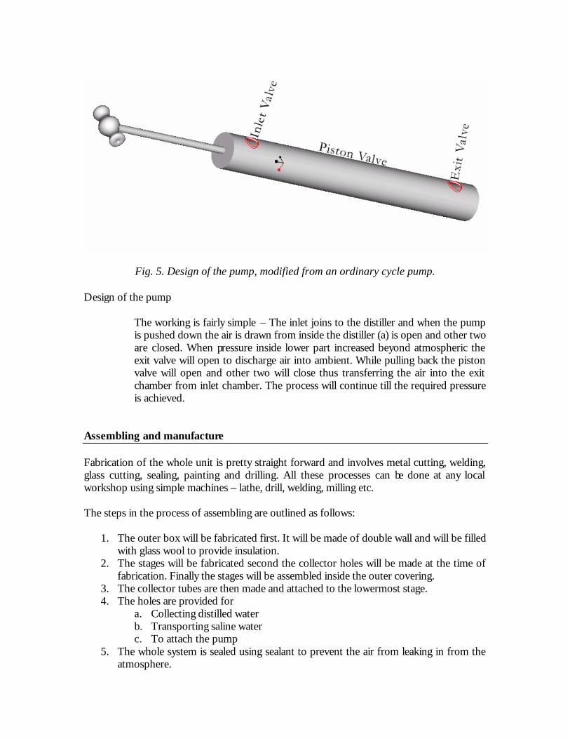
Fig. 5. Design of the pump, modified from an ordinary cycle pump. Design of the pump
The working is fairly simple – The inlet joins to the distiller and when the pump is pushed down the air is drawn from inside the distiller (a) is open and other two are closed. When pressure inside lower part increased beyond atmospheric the exit valve will open to discharge air into ambient. While pulling back the piston valve will open and other two will close thus transferring the air into the exit chamber from inlet chamber. The process will continue till the required pressure is achieved.
Assembling and manufacture Fabrication of the whole unit is pretty straight forward and involves metal cutting, welding, glass cutting, sealing, painting and drilling. All these processes can be done at any local workshop using simple machines – lathe, drill, welding, milling etc. The steps in the process of assembling are outlined as follows:
1. The outer box will be fabricated first. It will be made of double wall and will be filled with glass wool to provide insulation.
2. The stages will be fabricated second the collector holes will be made at the time of fabrication. Finally the stages will be assembled inside the outer covering.
3. The collector tubes are then made and attached to the lowermost stage. 4. The holes are provided for
a. Collecting distilled water b. Transporting saline water c. To attach the pump
5. The whole system is sealed using sealant to prevent the air from leaking in from the atmosphere.


6. Finally after the whole procedure is over the glass cover is installed on top. This is the last step as glass is the most fragile material we are using for the design.
1. fabricate the outer casing
2. fabricate the inner stages
3. fabricate the collector tubes
4. Provide holes for transport of distilled waterand saline water
5. Provide sealing
6. Finally put the glass cover
Fig. 6. Assembling procedure outline Working The working is based on phenomena of evaporation on absorption of heat from sunlight and subsequent condensation of vapor on contact with the cooler walls.
1. Pump is used to reduce the pressure inside the chamber to around 20 kPa to ensure boiling takes place at 60 oC.
2. The sunlight is captured by the glass cover and absorbed by the black floor of the top reservoir.
3. Water gets heated up and evaporates thus making the air saturated with vapor. 4. This water also supplies to the two stage troughs by means of tubes running down
and flow is controlled by the level control valves. 5. When this saturated air comes in contact with cooler glass cover it condenses and
forms droplets. Due to combined effect of inclination and gravity the droplets move and drop into the collector. This water is conveyed to the storage from here.
6. In the lowermost reservoir the water is heated up by means of the collector tubes – this serves dual purpose, first it introduces turbulence in water and hence enhances evaporation also it takes water from lower cooler layers and constantly heats it up to supply to the top layers thus mixing the heat evenly in the volume of water.
7. Water evaporates in the lowermost reservoir taking up heat for raising temperature and phase change. When this condenses on the cooler ceiling it gives out the latent heat and small amount of specific heat to the reservoir above it. Hence no heat is lost in the water going out in form of condensate but is reformed as useful heat for the next subsequent stage. This improves efficiency tremendously.

8. The same process as described in 7 repeats in the next two stages. This ensures maximum utilization of the captured heat and finally all the water falls into a common collector system which is so designed to minimize any sort of losses.
Materials
1. The side and bottom walls need to be insulated. This can be achieved by using multi-layered insulator. Glass wool will be sand-witched between two metallic plates. This will ensure negligible heat loss to the surroundings.
2. The main frame is composed of steel owing to its corrosion resistance, low weight, long life and easy cleanability.
3. The outside of the complete distiller is coated with carbon black to increase absorption of radiation.
4. The cover on the top is made of tempered glass so that the birds can’t see their reflection and hence avoid nuisence.
Usage The usage will involve following steps:-
1. The user will fill the reservoir tank with water that needs to be purified. 2. Attach the vacuum pump to the apparatus and operate it till the pressure inside
drops to around 20kPa. Then remove the pump. 3. Attach the pipe for collecting the purified water. 4. Then he will lift the whole device up a few meters above the ground (around 2.5 m).
This will ensure no shadows fall on the apparatus during any part of the day. 5. Leave it there till evening. 6. Remove the purified water for use. 7. Remove the plates for cleaning and dispose of the remaining water. 8. Ready for use on the next day.
Maintenance
1. The only maintenance that the device requires is replacement of the glass in case of accidental breakage.
2. Daily cleaning of the plates is required. 3. Sometimes the pump will need to be oiled and serviced. This cost might occur once
in 6 months or so. Cost Analysis The total area of the steel plates used = 4.5 m2 Rate of steel plate of thickness 1mm = 60/Kg Total cost of steel = Rs 400
Cost of crushed hay and sawdust = Almost free Cost of carbon black paint = Rs 20 Cost of tempered glass = Rs 200 Cost of insulation and sealing = Rs 80 Cost of the pump = Rs 100 Cost of the hoisting mechanism and other auxiliaries = Rs 50 Cost of labor and machining = Rs 130 Net cost of the device = Rs 980 The per- liter cost of solar-distilled water can be calculated as follows:
(a) estimate the usable lifetime of the still; (b) add up all the costs of construction, repair and maintenance (including labor) over its lifetime; and (c) divide that figure by the still's total expected lifetime output in liters.
Such a cost estimate is only approximate since there are large uncertainties in both the lifetime and the yield estimates. Costs are usually considerably higher than current water prices–which explains why solar backyard stills are not yet marketed widely in India. Market Research The market for the product includes whole of rural Indian population and some of the water scarce urban areas like Chennai. This comprises around 70% of India’s population. The exact number being 70cores. Assuming around 10 % of them will actually be interested in buying this product the demand for the product is 70*.1/5 = 1.4 crore units. This makes the market size to come up to around Rs 140 crore. Impact The impact of this kind of a product to the rural Indian will be tremendous. One of the greatest problems facing the Indian villages is that of drinking water. Water ranks very high on the United Nations’s list of scarce commodities that need urgent conservation measures. In the desert and other semi-arid regions this device will prove to be a great life saver. s

Second Design We would also like to present a second design that does not require vacuum pressures to operate. This will make the system much simpler and cheaper. For achieving better evaporation at lower temperatures in this case we make use of the phenomena called atomization. This is achieved as follows. The water is stored at a higher location under high pressure. The water is heated at this location by using the solar radiation entrapment using glass plate for green house effect. When water comes down to the distillation chamber both pressures and temperatures are high because of pgh term or pressure head and solar heating. This water is made to pass through a fine nozzle. This will ensure fine droplet formation and consequently very high rates of evaporation. The walls of the chamber are cooled by means of evaporative cooling of water on the layer of clay, as demonstrated in the diagram. When this moisture laden air comes in contact with the cool walls of the chamber condensation takes place and the water moves down to the collector drain.

Solar water heater
Pipe for raising pressure
Storage for water for keepingthe coating cool
Distillation ColumnWater will be sprayed from nozzle for better evaporation
The outside of the column is coatedwith clay to keep it cool by means of evaporativecooling