Software Defined Adaptive Codec for Cognitive Radio · Software Defined Adaptive Codec for...
10
Software Defined Adaptive Codec for Cognitive Radio RAJESHREE D. RAUT 1 AND KISHORE D. KULAT 2 Electronics & Communication Department 1 Department of Electronics & Computer Science 2 SRKNEC, Nagpur 1 VNIT, Nagpur 2 Katol Road, Gittikhadan, Nagpur, M.S. INDIA 1 [email protected] 1 Abstract: - Recently, Cognitive Radio has been proposed as a promising technology to improve spectrum utilization. A highly flexible SDR (Software defined Radio) system needs to configure each of its blocks to give optimum performance over the available bandwidth. Present work discusses an approach for software defined adaptive coder yielding minimum BER (Bit error rate) for emergency services over cognitive radio. The results verify the efficiency of the algorithm which configures the convolution encoder to produce a lower BER for increased Bandwidth available. This can be readily implemented in the SDR library functions. This has been tested by FPGA implementation of the convolution encoder using Matlab HDL coder. The coder output of the FPGA implemented VHDL code has also been presented. Various WiMax Systems to be included in the SDR Library are puttforth. SDR adapts to the best suitable design, yielding lower BER in available channel conditions. Key-Words: - Cognitive Radio, SDR library, Rate Adaptive Coder, BER, FPGA implementation. 1 Introduction Current wireless networks are characterised by a static spectrum allocation policy, where governmental agencies assign wireless spectrum to license holders on a long-term basis for large geographical regions [1]. Over last couple of years spectrum demand has increased many folds. Spectrum allocation policy has faced spectrum scarcity in particular spectrum bands. In contrast, a large portion of the assigned spectrum is used sporadically, leading to underutilization of significant amount of spectrum [2]. Spectral occupancy measurements consistently show that some bands are under-utilised in some areas at some times. Results from Ofcom website are depicted in fig.1. The blue bands are low signal levels, indicating sparse utilization of the spectrum Space, whereas the brown bands indicate high signal level that is heavy utilization of Spectrum Space. The inefficiency in Spectrum Utilization is obvious. Hence, dynamic spectrum access techniques were proposed to solve these spectrum inefficiency problems. The key enabling technology of dynamic spectrum access techniques is Cognitive radio. Joseph Mitola III and Gerald Q. Maguire who first officially presented the idea of Cognitive Radio [3], define it as “Cognitive radio is an intelligent wireless communication system that is aware of its Radio Frequency (RF) environment, and uses the methodology of understanding- by- building to learn from the environment and adapt its internal states to statistical variation in the environment by making changes to adjustable parameters, namely transmit power, carrier frequency and modulation strategy, all in real Time” [Mitola 1999]. This Paper introduces the Cognitive Concept, defines the problem as coder adaption to available bandwidth. Thereafter, puttsforth the algorithm of the Smart Codec for problem solution justifying its applicability by presenting the simulation and Hardware implementation results. Earlier work included transmitter power required and modulation strategy for WiMax System. It was shown that the OQPSK system in place of the conventional QPSK system improves BER performance and requires a lower transmit power [4]. The results of the same WSEAS TRANSACTIONS on COMMUNICATIONS Rajeshree D. Raut, Kishore D. Kulat ISSN: 1109-2742 1243 Issue 12, Volume 8, December 2009
Transcript of Software Defined Adaptive Codec for Cognitive Radio · Software Defined Adaptive Codec for...

Software Defined Adaptive Codec for Cognitive Radio
RAJESHREE D. RAUT1 AND KISHORE D. KULAT
2
Electronics & Communication Department1
Department of Electronics & Computer Science2
SRKNEC, Nagpur1
VNIT, Nagpur2
Katol Road, Gittikhadan, Nagpur, M.S.
INDIA1
Abstract: - Recently, Cognitive Radio has been proposed as a promising technology to improve spectrum
utilization. A highly flexible SDR (Software defined Radio) system needs to configure each of its blocks to
give optimum performance over the available bandwidth. Present work discusses an approach for software
defined adaptive coder yielding minimum BER (Bit error rate) for emergency services over cognitive radio.
The results verify the efficiency of the algorithm which configures the convolution encoder to produce a lower
BER for increased Bandwidth available. This can be readily implemented in the SDR library functions. This
has been tested by FPGA implementation of the convolution encoder using Matlab HDL coder. The coder
output of the FPGA implemented VHDL code has also been presented. Various WiMax Systems to be included
in the SDR Library are puttforth. SDR adapts to the best suitable design, yielding lower BER in available
channel conditions.
Key-Words: - Cognitive Radio, SDR library, Rate Adaptive Coder, BER, FPGA implementation.
1 Introduction Current wireless networks are characterised by a
static spectrum allocation policy, where
governmental agencies assign wireless spectrum to
license holders on a long-term basis for large
geographical regions [1]. Over last couple of years
spectrum demand has increased many folds.
Spectrum allocation policy has faced spectrum
scarcity in particular spectrum bands. In contrast, a
large portion of the assigned spectrum is used
sporadically, leading to underutilization of
significant amount of spectrum [2]. Spectral
occupancy measurements consistently show that
some bands are under-utilised in some areas at some
times. Results from Ofcom website are depicted in
fig.1. The blue bands are low signal levels,
indicating sparse utilization of the spectrum Space,
whereas the brown bands indicate high signal level
that is heavy utilization of Spectrum Space. The
inefficiency in Spectrum Utilization is obvious.
Hence, dynamic spectrum access techniques were
proposed to solve these spectrum inefficiency
problems.
The key enabling technology of dynamic spectrum
access techniques is Cognitive radio. Joseph Mitola
III and Gerald Q. Maguire who first officially
presented the idea of Cognitive Radio [3], define it
as “Cognitive radio is an intelligent wireless
communication system that is aware of its Radio
Frequency (RF) environment, and uses the
methodology of understanding- by- building to learn
from the environment and adapt its internal states to
statistical variation in the environment by making
changes to adjustable parameters, namely transmit
power, carrier frequency and modulation strategy,
all in real Time” [Mitola 1999].
This Paper introduces the Cognitive Concept,
defines the problem as coder adaption to available
bandwidth. Thereafter, puttsforth the algorithm of
the Smart Codec for problem solution justifying its
applicability by presenting the simulation and
Hardware implementation results. Earlier work
included transmitter power required and modulation
strategy for WiMax System. It was shown that the
OQPSK system in place of the conventional QPSK
system improves BER performance and requires a
lower transmit power [4]. The results of the same
WSEAS TRANSACTIONS on COMMUNICATIONS Rajeshree D. Raut, Kishore D. Kulat
ISSN: 1109-2742 1243 Issue 12, Volume 8, December 2009

have been depicted here and algorithms included in
SDR library.
2 Cognitive Radio A typical Cognitive Cycle begins with Radio
scene analysis, identifying the spectrum holes
(unoccupied or underutilized spectrum
spaces).Performs channel estimation for the channel
capacity, channel state, transmit power, transmit
frequency etc. Issues signal for transmit power
control and spectrum management (work on channel
estimation has regards use of RS encoder for
presence of Burst Errors has already been carried
out [4]). Finally establishes connection with proper
initial handshake with receiver. Figure below shows
the cognitive cycle [3].
Fig. 2 Cognitive Cycle
Depending on the set of parameters taken into
account in deciding on transmission and reception
changes, and for historical reasons, we can
distinguish certain types of cognitive radio. The
main two are:
2.1 Full Cognitive Radio ("Mitola radio"):
In this every possible parameter observable by a
wireless node or network is taken into account.
2.2 Spectrum Sensing Cognitive Radio:
In this only the radio frequency spectrum is
considered.
Besides the above types, based on the
Spectrum Bands available for communication
Cognitive radio can be further categorised into
the following two categories,:
2.3 Licensed Band Cognitive Radio:
In which cognitive radio is capable of using
bands assigned to licensed users, apart from
unlicensed bands, such as U-NII band or ISM-
Band. The IEEE 802.22 working group is
developing a standard for wireless regional area
network (WRAN) which will operate in unused
television channels.
2.4 Unlicensed Band Cognitive Radio:
This can only utilize unlicensed bands of radio
frequency spectrum. One such system is
described in the IEEE 802.15 Task group 2
specification, which focuses on the coexistence
of IEEE 802.11 and Bluetooth.
Main Functions of Cognitive Radio:
1. Spectrum Sensing- This involves Primary
Transmitter detection. Cognitive Radios must
have capability to determine if a signal from a
primary transmitter is locally available.
Matched Filter detection, Energy detection, etc
are the methods utilized for Primary
Transmitter detection. A method called
Cooperative detection is also sometimes
utilized, wherein information from multiple
Cognitive Radio users is incorporated for
primary user detection.
2. Spectrum Management- Spectrum analysis
& Spectrum decision are the important tasks to
be carried out in Spectrum Management.
3. Spectrum Mobility- This should ensure
seamless operation & accordingly exchange
operating frequencies.
4. Spectrum Sharing- Spectrum Scheduling
method takes care of sharing the available
spectrum.
Work presented here is for the Spectrum
Sensing Cognitive Radios. If the spectrum
sensed is with higher bandwidth than we have
two options:
• To transmit bulk data at higher data
rate e.g. real time applications like
Mobile Services.
• To transmit small packets of data with
high accuracy, required in Emergency
Services (time bound emergency
information should take care of data
reduction to minimum possible size so
as to utilize low data rates where BER
is low).
WSEAS TRANSACTIONS on COMMUNICATIONS Rajeshree D. Raut, Kishore D. Kulat
ISSN: 1109-2742 1244 Issue 12, Volume 8, December 2009

Work presented focuses on the second option
for improving the BER performance of the
system.
3 Modelling & Simulation of
Spectrum Sensing Smart Codec for
Cognitive Radio The first step in modeling was to prepare a
simple Digital Communication System model to test
the encoder decoder design. This was done using
Matlab Simulink. The Model is as shown in fig. 3.A
a complex convolutional encoder with a constraint
length of 7 (see Figure 4)was designed.
Fig 4. MATLAB Simulation of Convolution Encoder
The generator polynomials for this encoder are
g0 = 171oct
and g1 =133oct.
The encoder can easily be implemented in
hardware shift registers.
The first step is to represent the input bit string as
a polynomial. Any sequence of 0’s and 1’s can be
represented as a binary number or a polynomial.
The convolutional encoder for WiMAX (g0 =
171oct and g1 = 133oct) can be represented as
follows:
• g0 = 1 + D + D2 + D3 + D6
• g1 = 1 + D2 + D3 + D5 + D6
The convolutional encoder basically multiplies
the generator polynomials by the input bit string, as
follows:
• A(x) = g0(x) * I(x) = a b c … g
• B(x) = g1(x) * I(x) = P Q R … V
Interleaving the two outputs from the
convolutional encoder yields E(x) = aPbQcR … gV,
which can also be written as:
E(x) = (a0 b0 c0 … g0) + (0P0Q0R … 0V) =
A(x2) + x*B(x2)
Therefore, E(x) = A(x2) + x * B(x2) and A(x2) =
g0(x2) * I(x2)
and B(x2) = g1(x2) * I(x2), with the following:
E(x) = g0(x2) * I(x2) + x * g1(x2) * I(x2)
= I(x2) * (g0(x2) + x * g1(x2))
= I(x2) * G(x) where
G(x) = g0(x2) + x * g1(x2)
i.e. G(x) = 1 + x + x2 + x4 + x5 + x6 + x7 + x11
+ x12 + x13.
If the BER performance need to further
Improved a Turbo codec replaces the normal
convolutional codec.
TURBO ENCODER
It consists of two convolutional encoders. The
outputs of the turbo encoder are the information
sequence, together with the corresponding parity
sequence produced by first encoder and the parity
sequence produced by the second encoder block, the
input to second encoder is through interleaver,
which scrambles the data bit sequence. Simulation
model of Turbo encoder –decoder is shown in fig 5.
Fig. 5 SIMULINK Model of Turbo Encoder-Decoder
TURBO DECODER
Turbo decoder shown above in Fig. 5 uses
iterative decoding. The turbo code decoder is based
on a modified Viterbi algorithm that incorporates
WSEAS TRANSACTIONS on COMMUNICATIONS Rajeshree D. Raut, Kishore D. Kulat
ISSN: 1109-2742 1245 Issue 12, Volume 8, December 2009

reliability values to improve decoding performance.
The turbo decoder consists of M elementary
decoders - one for each encoder in turbo encoding
part. Each elementary decoder uses the Soft
Decision Viterbi Decoding to produce a soft
decision for each received bit. After an iteration of
the decoding process, every elementary decoder
shares its soft decision output with the other M - 1
elementary decoders.
After testing the functionality of the codec in the
DCOM System a gate level model of the encoder
was prepared, noting the fact that Matlab Simulink
to HDL Converter supports only the behavioral
level blocks. The Gate Level design of the Encoder
is as shown in fig. 6. These steps were carried out to
test the hardware implementation possibility of the
codec.
As seen in fig. 2 the Cognitive Cycle begins with
Radio Scene Analysis, Scanning for Spectrum
Holes(Unoccupied spectrum spaces). Once the
bandwidth is available, in the available bandwidth
the transmit frequency is decided. So an M-File for
bandwidth selection was written [5], [6]. Now the
input signal in a Digital Communication System is a
digital data (binary bits), obtained from an analogue
source. Common example of analogue source is a
Speech signal, which varies from 300Hz to 3300Hz.
This will decide how many digital data bits are
present over the observation time. In the model data
bits are randomly generated to represent random
speech signal. The bit generation frequency also
changes, considering the variations in human
speech. We are not concerned with the amplitude
variations. Adaption is with regards to frequency &
it should be shown that it is dependant on channel
bandwidth and is independent on the frequencies in
Input data. It is therefore that the model has been
worked out for varying frequencies of input data &
performs equally well over the entire specified
range of frequencies of input data. Thus, the model
now takes the shape with three user defined
parameters as viz.
1. Input data start frequency,
2. Input data End Frequency and
3. Observation Time.
A simple Digital Communication System for
commercial communication working over the
available bandwidth was modeled with rate ½
convolution encoder [4], [7]. This was termed as a
non adaptive system, wherein it was found that as
Bandwidth increases the BER also increases (graph
plotted is shown in fig. 8.
An adaptive physical layer schemes is the
transmitter action in response to time varying
channel quality which is related to many factors. A
reliable estimation of the channel transfer quality is
required for the next active transmit time slot so the
transmitter has to select appropriate modulation and
channel modes [8].To make the system adaptive i.e.
as bandwidth increases one should be able to send
data with higher accuracy, the codec algorithm is
made efficient with additional bits and additional
sequential & combinational logic. This definitely
increases the computational time but drastically
reduces the BER. High speed processors should take
care of this increase in computational time. Typical
values of computation time required for varying
number of bits per frame is quoted in Table 1.
Conginitive
Radio
Spectrum
Sensing
Congnitive
Radio
Adaptive
Systems
Parameter
B.W.
Adaptive
System
Reflection
Parameter
Rate
Rate
Adaptive
Systems
FPGA
Implementation
Of Rate
Adaptive coder
HDL Code of
Convolution
coder
Gate level
Design
Of coder
Simulink
to
HDL
Conversion
Simple
DCOM
system
Block chosen
codec
Configure
System to
this frequency
M File
for
DCOM
B.W
scanning
for transmit
frequency Fig. 7 Work Flow
TABLE I
BITS PER FRAME VS COMPUTATIONAL TIME & CORRESPONDING BER
S
r.
N
o
Bits per Frame Computation
Time
BER
1 5 3 min 0.1340 E -2
2 7 7 min 0.1184 E-2
3 10 15 min 10 sec 0.1071 E-2
4 15 1 hour 36 min 0.0750 E-2
The reduction in BER with adaptive coder is plotted
and the corresponding graph is shown in fig.9. The
convolution encoder in Matlab was HDL coded and
the code was downloaded in FPGA [9], [10]. The
Input data bits and coded output of the rate ½
encoder is also presented in the results. The entire
work flow can be briefly depicted in the block
diagram shown in fig.7.
WSEAS TRANSACTIONS on COMMUNICATIONS Rajeshree D. Raut, Kishore D. Kulat
ISSN: 1109-2742 1246 Issue 12, Volume 8, December 2009

4 Results The software chosen for modeling was Matlab 7.4.
The Computer used had a Pentium processor with
2.4 GHz processing speed & 512 Mb RAM. The
problem faced was that the simulation time taken
increases to hours, due to the computational time
required in finding the checksum bits that are
derived from input bit streams. Therefore to observe
the results in the form of bits on the computer screen
and to plot the graphs the working frequencies were
scaled down. The model works equally well at high
frequencies and was tested for few sample data at
high frequencies too. High frequency is high data bit
rate i.e. more no of bits in a given frame. Every
checksum bit is derived with a combinational and
sequential logic utilizing the input, as the input bit
stream.
The first model was of a simple non adaptive digital
communication system wherein the codec does not
adapt to the available bandwidth. It was found that
as the bandwidth increases the BER increases, as is
clear from graph in fig 8.
The second model was prepared with an algorithm
to adapt to the increasing bandwidth and utilizing
this bandwidth to make the data more secure i.e. to
reduce the BER.
The graph in fig. 9 shows that the adaptive codec
reduces the BER with increase in frame size that has
resulted from increase in bandwidth.
The simulation output of the FPGA
implemented HDL code of convolution encoder is
shown in fig.10 & fig.11
Fig. 8. BER on Y-Axis vs. Bits per frame on X- Axis for non adaptive
Codec
Fig 9. BER on Y-Axis Vs. Bits per frame on X-Axis for adaptive
Codec
Fig 10. 0 to 7 input bits & 0to 10 output coded bits waveform
Fig 11. 4 to 7 input bits & 0to 15 complete coded bits waveform.
BER
x E
-2
Bits/Frame
BER
x E
-2
Bits/Frame
WSEAS TRANSACTIONS on COMMUNICATIONS Rajeshree D. Raut, Kishore D. Kulat
ISSN: 1109-2742 1247 Issue 12, Volume 8, December 2009

The Simulation models in case of WiMax were
prepared for following four systems [4]:
1. WiMax using RS+ Convolutional Codec and
OQPSK [11]
2. Existing WiMax system(RS + Convolutional) and
QPSK
3. WiMax using RS+ Turbo Codec and QPSK
4. WiMax using Turbo Codec and QPSK
Each of them was observed for bit error rate at
different values of S/N (signal to noise ratio).
Graphs of S/N versus BER(bit error rate) were
plotted and are as shown in fig 12.
The SDR chooses the system design based
on the following observation, as is observed in fig
12.
1. The turbo concatenation with RS gives desired
performance of decreasing the bit error rate with
increasing S/N.
2. Using only Turbo codes for the Codec design,
works perfect as far as simulation is concerned. But
real time systems will introduce Burst errors. To
reduce burst errors RS coding is a must.
3. More over, it was observed that every system
requires different signal power for the receiver to
interpret the data. The Turbo concatenated system
works fine with low power signals as compared to
only RS codec system.
4. Also the OQPSK system can respond to much
low level signals in comparison with the existing
QPSK systems and produce a much lower BER.
4 Conclusion
Cognitive radio is an innovative technology
proposed to increase spectrum usage by allowing
dynamic allocation of the unused spectrum in
changing environments. By exploiting the existing
wireless spectrum opportunistically, Cognitive
Radio Networks are being developed to solve
current network problems resulting from the limited
available spectrum usage. Cognitive Network users
monitor the spectrum and are allowed to use it as
long as it does not interfere with primary users to
whom it has been licensed. We have proposed the
design of a Smart Codec using convolution codes
wherein the codec senses the spectrum available and
accordingly modifies the algorithm for coding –
decoding. The hardware encoder had been realized
by downloading the HDL code into FPGA. An
increase in bandwidth is utilized for reducing the
BER.
5 Work in Progress
Authors of the paper are actively involved in
performance improvement of BER. More precisely
when the channel is in Cognitive Network, adaption
to the available Bandwidth without deterioration of
the performance parameters is a must. Present work
focused on improving the BER performance with
availability of higher Bandwidth. The available BW
can be utilized to increase the data rates. In such
situations maintaining the BER performance seems
to be difficulty. A probable solution is use of
Multicarrier modulation, as suggested by Haitham J.
Taha & M. F. M. Salleh [12]. This has given me an
idea to carry out future work with Spread Spectrum
Techniques.
References:
[1] FCC, ET Docket No 03-322 Notice of
Proposed Rule Making and Order, Dec 2003.
[2] Jan F. Akyildiz & etal, “ A Survey on
Spectrum Management in Cognitive Radio
Netwarks”, IEEE Communication Magazine,
vol 46, pp. 40-48, April 2008.
[3] Marco Chiani, “ Coexistence of Ultra- Wide
band and other Wireless Systems: the Path
Towards Cognitive Radio”, UWB Workshop,
Ferrara: 2008.
[4] R. D. Raut and K. D. Kulat, “ Novel approach:
Codec design for WiMax system”, IEEE
Explore, 18-20 Dec,2008
[5] Matlab 7 Getting Started Guide, Available:
http://www.Mathwaorks.com
[6] Simulink Fixed Point 5 User’s Guide,
Available: http://www.Mathwaorks.com
[7] R.D. Raut and K. D.Kulat, “Optimal Coec
Design for Mobile Communication”,
TECHNIA, International Journal of
Computing Science & communication
Technologies , vol 1, no. 1, pp.. 20-24, July
2008.
[8] *Lamia Chaari , Mohamed Fourati, Nouri
Masmoudi, Lotfi Kamoun, “ An Adaptive
coded modulation with multi-levels QоS
analysis in multimedia environment”, WSEAS
WSEAS TRANSACTIONS on COMMUNICATIONS Rajeshree D. Raut, Kishore D. Kulat
ISSN: 1109-2742 1248 Issue 12, Volume 8, December 2009

Transactions on Communications, Issue6, Vol
8, June 2009, pp 495-504.
[9] Doglas L. Perry, “VHDL Programming by
Example”, TMH. Fourth Edition.
[10] FPGA & CPLD Solutions from Xilinx Inc.,
Available:http://www.xilinx.com.
[11] *Natasa Zivic and Christoph Ruland, “Channel
Coding as a Cryptography Enhancer”, WSEAS
Transactions on Communications, Issue 2,
Vol7, Feb 2008, pp83-91
[12] *Haitham J. Taha, M. F. M. Salleh, “Multi-
carrier Transmission Techniques for Wireless
Communication Systems: A Survey, WSEAS
Transactions on Communications, Issue 5, Vol
8, May 2009, pp 457- 469
[13] Tomoaki Ohtsuki, “Rate Adaptive Indoor
Infrared Wireless Communication Systems
Using Repeated and Punctured Convolutional
Codes”, IEEE, 1999.
[14] Richard Lau and etal., “Cognitive Adaptive
Radio Teams”, work supported by DARPA
[15] Qiwei Zhang and etal.,“ Adaptive OFDM
System Design For Cognitive Radio”
[16] Amalia Roca, “Implementation of WiMax
Simulator in Simulink”, Vienna, Feb 2007
[17] Claudio Sacchi, Olga Zlydareva, “Object-
Oriented Model for SDR Library for WiMax/
UMTS System Baseband Level”, Technical
Report, University of Trento, Department of
Information and Communication Technology,
April 2007
[18] R. D. Raut & K. D. Kulat, “ Application
Specific Codec Design for Cognitive Radio”,
IJFCA, International Journal on Futuristic
Computer Applications, ISC Bangalore (paper
Selected)
‘*’ Indicates the references from WSEAS
Transactions
Fig.1. Spectral Occupancy Measurements From Ofcom Web Site- http://www.ofcom.org.uk/research/technology/research/emer_tech/cograd/
WSEAS TRANSACTIONS on COMMUNICATIONS Rajeshree D. Raut, Kishore D. Kulat
ISSN: 1109-2742 1249 Issue 12, Volume 8, December 2009

Viterbi Decoder
Viterbi Decoder
Scope4
Scope3
Scope1
Scope
PN Sequence
Generator
PN Sequence
Generator
Integer to Bit
Converter 1
Integer to Bit
Converter
Convolutional
Interleaver
Convolutional
Interleaver
Convolutional
Encoder
Convolutional
Encoder
Convolutional
Deinterleaver
Convolutional
Deinterleaver
Bit to Integer
Converter
Bit to Integer
Converter
Fig. 3 Simulation Model of Simple Digital Communication System, prepared in Matlab Simulink
Fig 6 Gate Level Design of the Convolution Encoder for Simulink to HDL Conversion
Fig. 6 Gate Level Design of the Convolution Encoder for Simulink to HDL Conversion
U n it D e la y 2
1 / z
U n it D e la y 1
1 /z
U n it D e la y
1 /z
S c o p e 6
S c o p e 5
S c o p e 4 S c o p e 3 S c o p e 2 S c o p e 1
S c o p e
P N S e q u e n c e
G e n e ra t o r
P N S e q u e n c e
G e n e ra t o r
M o d e l
s w ith
In 1
In 2
O u t 1
L o g ic a l
O p e ra to r 1
L o g ic a l
O p e ra t o r
Scope3
ScopeRandom
Interleaver
Random
Interleaver
Random
Deinterleaver
Random
Deinterleaver
PN Sequence
Generator
PN Sequence
Generator
Binary Symmetric
Channel
BSC
Err
Binary
Linear Encoder
Linear Encoder
Binary
Linear Decoder
Linear Decoder
WSEAS TRANSACTIONS on COMMUNICATIONS Rajeshree D. Raut, Kishore D. Kulat
ISSN: 1109-2742 1250 Issue 12, Volume 8, December 2009
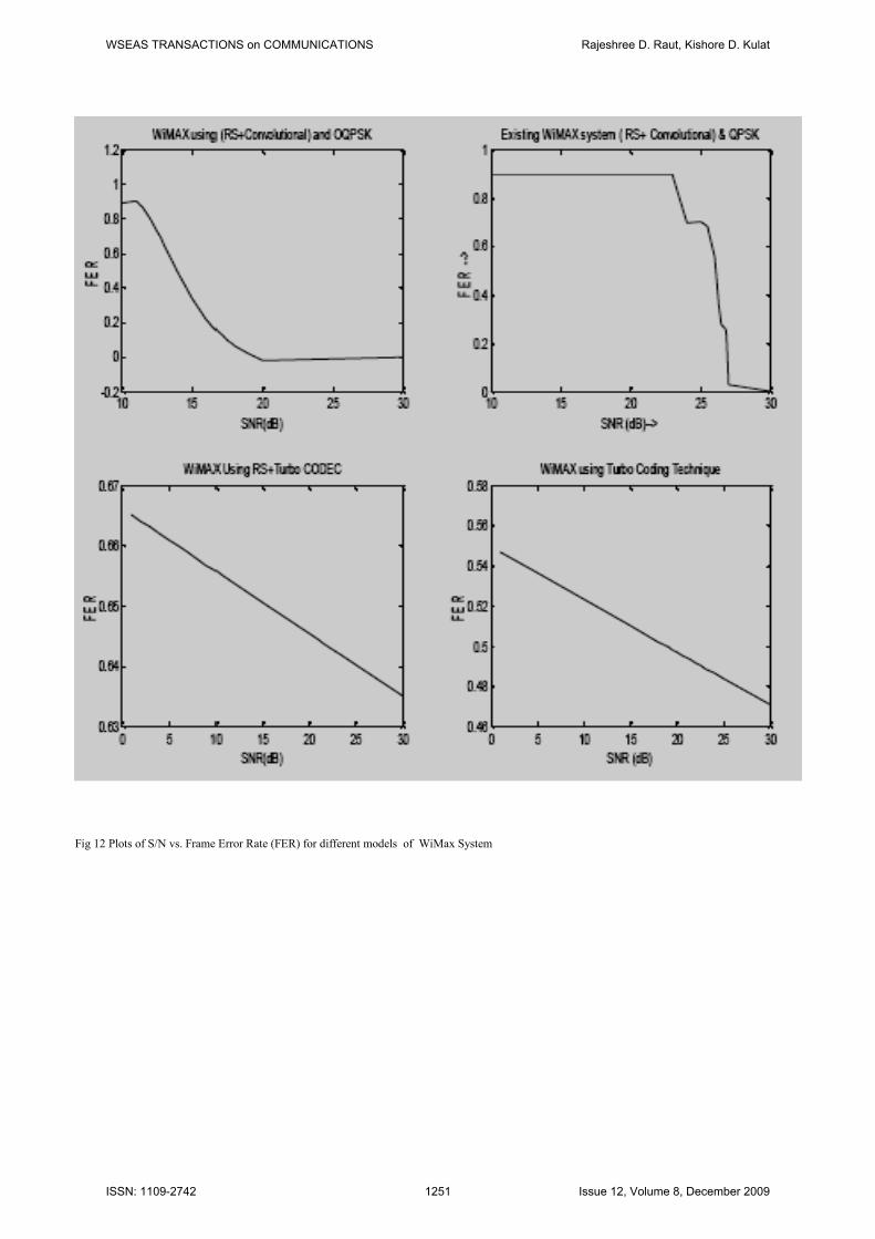
Fig 12 Plots of S/N vs. Frame Error Rate (FER) for different models of WiMax System
WSEAS TRANSACTIONS on COMMUNICATIONS Rajeshree D. Raut, Kishore D. Kulat
ISSN: 1109-2742 1251 Issue 12, Volume 8, December 2009

Acknowledgments This work is funded by the Research &
Development Department of Shri Ramdeobaba
Kamla Nehru Engineering College, Nagpur, M. S.,
India.
Author Biography
Dr. Kishore D. Kulat
Dr. Kishore D. Kulat completed his degrees in
Electrical Engineering, BE in 1980, from VRCE (at
present VNIT) Nagpur and ME degree in 1984 from
VJTI, Mumbai, India. He completed his Ph.D.
degree in Electronics Engineering, in the year 2003
from VNIT, Nagpur. Having a total experience of
more than 25 years, he is currently associated with
VNIT, as Professor in the Electronics & Computer
Science Department. With his profound knowledge
& experience in his field he is guiding around 15
research scholars for their doctoral degree. Two
have been awarded the Ph. D. degree. He has
published around 15 Journal Papers, more than 25
papers in International Conferences & more than 40
have been published in National Conferences. Has
worked as Reviewer for many National &
International Conferences. He is a member of Board
of Studies for Electronics Engineering, Nagpur
University for last 10years. He is member of
Professional societies like IETE, IEI and ISTE.
With all his faith in God, Dr. K. D. Kulat believes in
achieving excellence through the process of
continuous upgradation.
Prof. Rajeshree D.
Raut
Prof. Rajeshree D. Rraut, born on Aug. 2nd
, 1976,
completed her bachelor’s degree in Electronics &
Telecommunication Engineering, from Government
College of Engineering, Amravati, M.S., India. She
Completed her Masters in Electronics from the same
institute in 2002. She is submitting her Ph. D in
Error Control Coding for performance improvement
in Bit Error Rate in January 2010. Having an
experience of 11 years, she currently associated as
an Assistant Professor, with Electronics &
Communication Engineering Department of Shri
Ramdeobaba Kamla Nehru engineering College,
Nagpur, M.S., India. She has 04 International
Journal Papers, 05 International Conference, and
over 10 National Conference papers on accord. She
has worked as a Reviewer for IEEE TENCON,
Singapore. She delivered expert talks in the field.
She is the member of professional bodies like ISTE,
IETE & WSEAS. She believes “Work is Worship”.
WSEAS TRANSACTIONS on COMMUNICATIONS Rajeshree D. Raut, Kishore D. Kulat
ISSN: 1109-2742 1252 Issue 12, Volume 8, December 2009