SOFTWARE COMMUNICATIONS ARCHITECTURE … · 3.16 What elements of OMG IDL are allowed in the PIM?...
77
SCA Specification 4.0 User‘s Guide Version: 1.0 07 November 2012 i SOFTWARE COMMUNICATIONS ARCHITECTURE SPECIFICATION 4.0 USER'S GUIDE 07 November 2012 Version: 1.0 Prepared by: Joint Tactical Networking Center 33000 Nixie Way San Diego, CA 92147-5110 Statement A - Approved for public release; distribution is unlimited (07 November 2012) Notice: This document should be considered draft. JTNC is soliciting feedback and review from community, especially in regards to sections 3.22.2 and 3.23. Comments and suggestions may be emailed directly to: [email protected]
Transcript of SOFTWARE COMMUNICATIONS ARCHITECTURE … · 3.16 What elements of OMG IDL are allowed in the PIM?...

SCA Specification 4.0 User‘s Guide Version: 1.0
07 November 2012
i
SOFTWARE COMMUNICATIONS ARCHITECTURE
SPECIFICATION 4.0
USER'S GUIDE
07 November 2012
Version: 1.0
Prepared by:
Joint Tactical Networking Center
33000 Nixie Way
San Diego, CA 92147-5110
Statement A - Approved for public release; distribution is unlimited (07 November 2012)
Notice: This document should be
considered draft. JTNC is soliciting
feedback and review from community,
especially in regards to sections 3.22.2
and 3.23. Comments and suggestions
may be emailed directly to:

SCA Specification 4.0 User‘s Guide Version: 1.0
07 November 2012
ii
REVISION SUMMARY
Version Revision
0.3 Initial Release
1.0 SCA 4.0 Release

SCA Specification 4.0 User‘s Guide Version: 1.0
07 November 2012
iii
TABLE OF CONTENTS
1 SCOPE ........................................................................................................................................ 9
1.1 Informative References ............................................................................................................ 9
2 SCA INTRODUCTION .......................................................................................................... 10
2.1 Separation of Waveform and Operating Environment ....................................................... 10
2.2 Operating Environment ......................................................................................................... 10
2.2.1 Application Environment Profiles ...................................................................................... 10
2.2.2 Middleware and Data Transfer ........................................................................................... 11
2.3 JTRS Application Program Interfaces ................................................................................. 11
3 TOPIC ORIENTED GUIDANCE AND SUPPLEMENTARY INFORMATION ............ 13
3.1 CORBA profiles ...................................................................................................................... 13
3.1.1 Guidance on the use of Any ................................................................................................ 13
3.1.1.1 Rationale for restrictions on the use of Any .............................................................. 13
3.1.2 Guidance on the availability of commercial ORBs implementing these profiles ............... 13
3.1.3 Use Case for the Lightweight profile .................................................................................. 13
3.1.4 Guidance on restriction interface data types ....................................................................... 15
3.1.5 Rationale for CORBA feature inclusion in the profiles ...................................................... 15
3.2 Push model ............................................................................................................................... 15
3.2.1 Overview ............................................................................................................................. 15
3.2.2 External framework management ....................................................................................... 17
3.2.3 Registered and obtainable provides ports ........................................................................... 18
3.2.3.1 Registered provides ports ........................................................................................... 18
3.2.3.2 Obtainable provides ports .......................................................................................... 19
3.3 Enhanced Application Connectivity ...................................................................................... 20
3.3.1 Background ......................................................................................................................... 20
3.4 Nested applications ................................................................................................................. 21
3.4.1 Use cases for nested applications ........................................................................................ 21
3.4.2 How nested applications work in the SCA 4.0 ................................................................... 23
3.4.2.1 ApplicationFactoryComponent support for nested applications ............................... 23
3.4.2.2 ApplicationManagerComponent support for nested applications ............................. 25
3.5 Application Interconnection .................................................................................................. 25
3.5.1 Overview ............................................................................................................................. 25
3.5.2 Use case for interconnecting applications .......................................................................... 26
3.5.3 Application interconnection design .................................................................................... 26
3.5.4 Application interconnection implementation ...................................................................... 27

SCA Specification 4.0 User‘s Guide Version: 1.0
07 November 2012
iv
3.5.5 ApplicationFactoryComponent support for interconnected applications ........................... 28
3.6 Enhanced allocation property support ................................................................................. 29
3.6.1 Overview ............................................................................................................................. 29
3.6.2 Descriptor structure for nested applications ....................................................................... 30
3.6.3 Enhanced Allocation Properties in SCA 4.0 ....................................................................... 30
3.6.4 Dependency Hierarchies in SCA 4.0 .................................................................................. 31
3.7 SCA Waveform Construction ................................................................................................ 34
3.7.1 Overview ............................................................................................................................. 34
3.7.2 FM3TR waveform example ................................................................................................ 34
3.8 Resource and Device Interface Decomposition .................................................................... 36
3.8.1 Overview ............................................................................................................................. 36
3.8.2 Resource Related Modifications ......................................................................................... 37
3.8.2.1 Resource interface changes ........................................................................................ 37
3.8.2.2 ComponentFactory Interface Changes ...................................................................... 39
3.8.3 Device Related Modifications ............................................................................................ 39
3.8.3.1 Device and LoadableDevice interface changes ......................................................... 39
3.8.3.2 ExecutableDevice Interface Changes ......................................................................... 41
3.8.4 Summary ............................................................................................................................. 42
3.9 Refactored CF Control and Registration Interfaces ........................................................... 42
3.9.1 Overview ............................................................................................................................. 42
3.9.2 DeviceManager Interface Changes ..................................................................................... 43
3.9.3 DomainManager interface changes .................................................................................... 45
3.9.4 Application Interface Changes ............................................................................................ 47
3.9.5 ApplicationFactory Interface Changes ............................................................................... 48
3.9.6 Summary ............................................................................................................................. 49
3.10 Static Deployment ................................................................................................................... 49
3.10.1 Overview ............................................................................................................................. 49
3.10.2 Deployment Background .................................................................................................... 50
3.10.3 Connection Management .................................................................................................... 50
3.10.4 Example .............................................................................................................................. 51
3.11 Lightweight Components ....................................................................................................... 51
3.11.1 Overview ............................................................................................................................. 51
3.11.2 Benefits ............................................................................................................................... 52
3.11.3 Alternative Solutions .......................................................................................................... 53
3.11.4 Implementation Considerations .......................................................................................... 56
3.12 SCA Next Development Responsibilities .............................................................................. 56
3.12.1 Overview ............................................................................................................................. 56
3.12.2 Component Development Alignment ................................................................................. 56

SCA Specification 4.0 User‘s Guide Version: 1.0
07 November 2012
v
3.12.3 Component Products ........................................................................................................... 57
3.13 Component Model ................................................................................................................... 58
3.13.1 Overview ............................................................................................................................. 58
3.13.2 Interfaces and Components ................................................................................................. 59
3.13.3 Benefits and Implications ................................................................................................... 60
3.14 SCA Maintanence Process – How To Develop a New PSM? .............................................. 62
3.14.1 Overview ............................................................................................................................. 62
3.14.2 SCA Change Proposal Process – Submitter Roles ............................................................. 62
3.15 Units of Functionality and SCA Profiles ............................................................................... 63
3.15.1 Overview ............................................................................................................................. 63
3.15.2 SCA UOFs and Profiles ...................................................................................................... 64
3.15.3 Use of UOFs and Profiles ................................................................................................... 64
3.16 What elements of OMG IDL are allowed in the PIM? ....................................................... 66
3.16.1 Overview ............................................................................................................................. 66
3.16.2 PIM Background ................................................................................................................. 66
3.16.3 PIM usage for SCA developers .......................................................................................... 66
3.16.4 Future PIM evolution .......................................................................................................... 66
3.17 What is the Impact of the SCA 4.0 Port changes? ............................................................... 66
3.17.1 Overview ............................................................................................................................. 66
3.17.2 Port Revisions ..................................................................................................................... 67
3.17.3 Interface and Implementation Differences ......................................................................... 67
3.17.4 Implementation Implications .............................................................................................. 68
3.18 Rationale for DeviceManagerComponent Registration ...................................................... 69
3.19 Rationale for Removal of Application Release Requirement ............................................. 69
3.20 How to Find and Use Domain Registry References ............................................................. 70
3.20.1 Overview ............................................................................................................................. 70
3.20.2 PlatformComponent registration approaches ...................................................................... 71
3.20.3 Implementation approach ................................................................................................... 71
3.21 Legacy Support Via V222_COMPAT Directive .................................................................. 72
3.22 Component Life Cycle ............................................................................................................ 72
3.22.1 Overview ............................................................................................................................. 72
3.22.2 ComponentBase State Model <Requesting Additional Input> ......................................... 72
3.23 Configuration Properties <Requesting Additional Input> ................................................... 73
3.24 Bypass ...................................................................................................................................... 73
3.24.1 Overview ............................................................................................................................. 73
3.24.2 Definitions .......................................................................................................................... 74

SCA Specification 4.0 User‘s Guide Version: 1.0
07 November 2012
vi
4 ACRONYMS ............................................................................................................................ 76

SCA Specification 4.0 User‘s Guide Version: 1.0
07 November 2012
7
Figure 1 Example Radio Powered by SCA 4.0 ................................................................................ 10
Figure 2 JTR Set and Waveform Interfaces ...................................................................................... 12
Figure 3 Lightweight Component in Lightweight profile ................................................................ 14
Figure 4 Component distributed across multiple processing elements ............................................. 14
Figure 5 Distributed component with FPGA portion ....................................................................... 15
Figure 6 Pull model registration ....................................................................................................... 16
Figure 7 Push model registration ...................................................................................................... 17
Figure 8 External framework management ...................................................................................... 18
Figure 9 Registered port management .............................................................................................. 19
Figure 10 Obtainable port management ............................................................................................ 19
Figure 11 Port lifecycles ................................................................................................................... 20
Figure 12 Simple nested application ................................................................................................. 22
Figure 13 Security domain divided application ................................................................................ 23
Figure 14 Inter-application connections ........................................................................................... 27
Figure 15 Connectivity specific example ......................................................................................... 28
Figure 16 Inter-application connections with external ports ............................................................ 29
Figure 17 Dependency Hierarchy ..................................................................................................... 32
Figure 18 Dependency Hierarchy and Sub-Applications ................................................................. 33
Figure 19 Allocation property examples .......................................................................................... 33
Figure 20 Example FM3TR SCA Waveform Design ....................................................................... 35
Figure 21 Example Deployment of FM3TR ..................................................................................... 36
Figure 22 ExecutableDevice Interface Inheritance Relationship ..................................................... 37
Figure 23 Resource Interface Refactoring ........................................................................................ 38
Figure 24 Resource Interface Optional Interfaces ............................................................................ 38
Figure 25 ResourceFactory Interface Refactoring ............................................................................ 39
Figure 26 Device Interface Inheritance Refactoring ......................................................................... 40
Figure 27 Device Interface Refactoring ............................................................................................ 40
Figure 28 LoadableDevice Interface Refactoring ............................................................................. 41
Figure 29 ExecutableDevice Interface Refactoring .......................................................................... 42
Figure 30 DeviceManager Interface Refactoring – registration operations ..................................... 43
Figure 31 DeviceManager Interface Refactoring – attributes .......................................................... 44
Figure 32 DeviceManager Interface Refactoring – miscellaneous operations ................................. 45
Figure 33 DomainManager Interface Refactoring – registration operations .................................... 46
Figure 34 DomainManager Interface Refactoring – manager registration operations ..................... 47
Figure 35 DomainManager Interface Refactoring – installation operations .................................... 47
Figure 36 Application Interface Refactoring .................................................................................... 48
Figure 37 ApplicationFactory Interface Refactoring ........................................................................ 49
Figure 38 ApplicationFactory Role in Component Deployment ...................................................... 50

SCA Specification 4.0 User‘s Guide Version: 1.0
07 November 2012
8
Figure 39 Resource Interface Optional Inheritance .......................................................................... 52
Figure 40 Component Optional Realization ..................................................................................... 53
Figure 41 Optional Realization Issues .............................................................................................. 53
Figure 42 Component Optional Inheritance ..................................................................................... 54
Figure 43 Lightweight Components within an Address Space ......................................................... 55
Figure 44 Successful Use of Lightweight Components .................................................................... 55
Figure 45 General Allocation of Components to Radio Developers ................................................ 57
Figure 46 SCA Component Relationships ........................................................................................ 59
Figure 47 SCA Change Proposal Process ......................................................................................... 62
Figure 48 SCA Profiles with OE Units of Functionality .................................................................. 65
Figure 49 Port Interface Refactoring ................................................................................................ 67
Figure 50 Port Implementation Differences ..................................................................................... 68
Figure 51 Sequence Diagram depicting application release behavior .............................................. 70
Figure 52 Resource Interface Features Optional Inheritance ........................................................... 71
Figure 53 Resource Interface Features Optional Inheritance ........................................................... 72
Figure 54 Component Life Cycle ..................................................................................................... 73
Figure 55 Illustration of Bypass Concepts ........................................................................................ 75

SCA Specification 4.0 User‘s Guide Version: 1.0
07 November 2012
9
1 SCOPE
This User‘s Guide is intended to provide practical guidance and suggestions for developing
Software Communications Architecture (SCA) compliant products. It is not a substitute for the
SCA specification, but a companion document to provide implementation guidance and design
rationale outside the structure of a formal specification. This document will expand in content and
detail as SCA user experiences accumulate.
1.1 INFORMATIVE REFERENCES
The following is a list of documents referenced within this specification or used as reference or
guidance material in its development.
[1] Software Communications Architecture Specification Appendix B: SCA Application
Environment Profiles, Version 4.0, 28 February 2012
[2] Common Object Request Broker Architecture (CORBA) Specification, Part 1: CORBA
Interfaces, Version 3.2 formal/2011-11-01, November 2011.
[3] Common Object Request Broker Architecture (CORBA) for embedded Specification,
Version 1.0 formal/2008-11-06, November 2008.
[4] Software Communications Architecture Specification Appendix E-1 - Attachment 1: SCA
CORBA Profiles (from CORBA/e), Version 4.0, 28 February 2012
[5] Software Communications Architecture Specification Appendix D - Platform Specific
Model (PSM) - Domain Profile Descriptor Files, Version 4.0, 28 February 2012
[6] Software Communications Architecture Specification Appendix F - Units of Functionality
and Profiles, Version 4.0, 28 February 2012
[7] UMLTM
Profile for CORBATM
Specification, Version 1.0 formal/2002-04-01, April 2002.
[8] Software Communications Architecture Specification Appendix E-3: Platform Specific
Model (PSM) - Object Management Group Interface Definition Language, Version 4.0, 28
February 2012
[9] Donald R. Stephens, Cinly Magsombol, Chalena Jimenez, "Design patterns of the JTRS
infrastructure", MILCOM 2007 - IEEE Military Communications Conference, no. 1,
October 2007, pp. 835-839
[10] Cinly Magsombol, Chalena Jimenez, Donald R. Stephens, "Joint tactical radio system—
Application programming interfaces", MILCOM 2007 - IEEE Military Communications
Conference, no. 1, October 2007, pp. 855-861
[11] Donald R. Stephens, Rich Anderson, Chalena Jimenez, Lane Anderson, "Joint tactical radio
system—Waveform porting", MILCOM 2008 - IEEE Military Communications
Conference, vol. 27, no. 1, November 2008, pp. 2629-2635
[12] JTRS Waveform Portability Guidelines,
http://jpeojtrs.mil/sca/Pages/portabilityguidelines.aspx
[13] JTRS Open Source Information Repository, http://gforge.calit2.net/gf/project/jtrs_open_ir/

SCA Specification 4.0 User‘s Guide Version: 1.0
07 November 2012
10
2 SCA INTRODUCTION
2.1 SEPARATION OF WAVEFORM AND OPERATING ENVIRONMENT
A fundamental feature of the SCA is the separation of waveforms from the radio‘s operating
environment. Waveform portability is enhanced by establishing a standardized host environment
for waveforms, regardless of other radio characteristics. An example diagram of an SCA-based
radio is illustrated in Figure 1. The waveform software is isolated from specific radio hardware or
implementations by standardized APIs.
Figure 1 Example Radio Powered by SCA 4.0
2.2 OPERATING ENVIRONMENT
2.2.1 Application Environment Profiles
To promote waveform portability among the many different choices of operating systems, the SCA
specifies the operating system functionality relative to IEEE POSIX options and units of
functionality. The Application Environment Profiles (AEP) specification, reference [1], identifies
specific operations such as pthread_create(), open(), etc., that are available for use by
ApplicationResourceComponents and must be provided by the radio platform. A platform
developer may provide additional operating system functions, but the waveforms can only access
the functions defined in the AEP. This assures any SCA compliant radio can execute the
waveform.
SCA defines two profiles, AEP and Lightweight (LwAEP), that may be used across a range of
radio sets ranging from a small handheld to a multichannel radio embedded within an aircraft. The
LwAEP is a subset of the AEP and intended for very constrained processors such as DSPs that
typically do not support more capable real-time operating systems.

SCA Specification 4.0 User‘s Guide Version: 1.0
07 November 2012
11
Some waveforms may require networking functions such as socket() or bind(). If a radio platform
is going to host waveforms that utilize those operations, it must support the Networking
Functionality AEP as an extension to the primary AEP profile. Reference [4] provides additional
information related to networking.
2.2.2 Middleware and Data Transfer
In Figure 1, the radio platform provides middleware and data/messaging transport in addition to the
real-time operating system. Middleware is a generalized service which facilitates messaging
between software components, possibly hosted on separate processors. SCA 2.2.2 and its
predecessors mandated CORBA as the middleware layer and deferred the specific transport
mechanism to the radio set developer. Historical data transfer mechanisms have been TCP-IP and
shared memory. The former can introduce substantial latency and perhaps has unfairly tarnished
CORBA‘s reputation within the radio community. A faster transport such as shared memory
generally yields latencies acceptable for high-data rate waveforms.
SCA 4.0 deleted the CORBA requirement and defined middleware independent APIs, although
they are still specified in interface definition language (IDL) (see reference [2]). Radio developers
may continue using CORBA, or select a different middleware such as the lightweight Remote
Procedure Call (RPC) used by the Android platform. Waveforms would require recompilation for
different middleware implementations, but the APIs should remain the same for the most part, thus
maximizing waveform portability.
2.3 JTRS APPLICATION PROGRAM INTERFACES
Figure 1 contains several independent APIs which separate the waveform from the radio set. The
primary emphasis of the JTRS API standardization efforts has been upon interfaces between the
waveform and radio set such as those illustrated in Figure 2. The internal interfaces and transport
mechanisms of the radio are defined as necessary by the radio provider. The underlying intent is to
provide portability or reuse of the waveform between radio platforms and not necessarily
portability of the radio operating environment software. For additional discussion on waveform
portability, see [11] and [12].

SCA Specification 4.0 User‘s Guide Version: 1.0
07 November 2012
12
Wa
ve
form
Ap
plic
atio
nHMI
Service
System
Control
Modem
Device
Audio
Device
Modem
Hardware
Audio
Hardware
Standardized
JTR Set APIs
Operator
Control
Set-Specific
Interfaces
Figure 2 JTR Set and Waveform Interfaces
There has been a conscious effort to maintain a clear separation between the SCA and the JTRS
APIs which define services provided by the radio set to the waveform such as GPS, time, etc. The
distinction not only maintains the integrity of SCA framework and preserves its applicability across
a wide range of domains, but also allows the content of each family of specifications to evolve
according to its own timetable. A partial list of the JTRS APIs is provided in Table 1. The APIs
have been developed with software design patterns to define a scalable and extensible
infrastructure. See [9] and [10] for an introduction to the aggregation, least privilege, extension,
explicit enumeration, and deprecation design patterns for JTRS APIs.
Table 1 Partial List of JTRS APIs
Audio Port Device API Ethernet Device API
Frequency Reference Device API GPS Device API
Modem Hardware Abstraction Layer (MHAL) API Serial Port Device API
Timing Service API Vocoder Service API
MHAL On Chip Bus (MOCB) API Packet API
JTRS Platform Adapter (JPA) API
The JTRS Platform Adapter (JPA) identified in Table 1 is both an API and a design pattern for
controlling the waveform by the radio set. (It is a particularly vexing problem, to define a portable
command/control interface for waveforms across multiple radio sets.) This API uses the SCA
PropertySet interface as a container for waveform parameters controlled and manipulated by the
radio set. It also supports bidirectional communication, permitting the waveform to provide status
to the radio set.

SCA Specification 4.0 User‘s Guide Version: 1.0
07 November 2012
13
3 TOPIC ORIENTED GUIDANCE AND SUPPLEMENTARY
INFORMATION
3.1 CORBA PROFILES
3.1.1 Guidance on the use of Any
On systems with limited resources, the use of the OMG IDL Any data type should be minimized.
The Any data type should not be used within the data path or in situations with demanding
performance requirements. When an Any type must be used, it should be associated with a simple
type. The CF::Properties data type is the SCA location that contains an Any data type within its
data structure definition.
3.1.1.1 Rationale for restrictions on the use of Any
The Any data type should be avoided due to the significant performance and resource consumption
implications that it levies on the method calls that use them. Many ORB providers supply insertion
and extraction operations for known simple types and transport them without large TypeCodes that
can add significantly to message sizes (in some cases the type information can more than double
the size of the messages). The potential size implications are even greater for complex types, the
CORBA compiler must generate code for insertion and extraction and add it to each component
using the interface as well as adding the type information to each message.
The additional size and processing complexity associated with marshaling and unmarshalling
utilizes resources that could be better directed towards providing application critical capabilities.
It is not necessary to find an ORB that does not support complex types in Any, or to try to remove
the capability from a commercial product because most of the resource savings is achieved not
from absence of the capability, but because the Application did not use that capability. However,
for user defined IDL types the Any capability is only turned on when the operator is generated by
the IDL compiler and used by the code. Some ORBs have the ability to optimize for size by only
including the Any capability when it is linked with the application through the use of a modular
architecture.
3.1.2 Guidance on the availability of commercial ORBs implementing these profiles
Initially there may be few, if any, commercial ORBs available that provide an implementation
tailored in accordance with the SCA specified profiles. With few noted exceptions, the Full and
Lightweight CORBA profiles are proper subsets of the CORBA/e Compact profile (see reference
[3]). This means that a processing element with sufficient resources could use a CORBA/e
Compact ORB and support nearly all permitted Application features and require minimal porting
effort.
3.1.3 Use Case for the Lightweight profile
The Lightweight profile is intended for extremely limited processing elements, such as most DSPs,
and assumes an approach for implementing SCA components (Resource or Device) that strives to
maximize performance and minimize resource utilization. In order to avoid resource intensive
features of the SCA for component management, such as the Resource interface and its inherited
PropertySet interface, the Lightweight profile accommodates partially realized SCA components,
Figure 3, or scenarios where the complete SCA component implementation is split between an
extremely limited and a somewhat less limited processing element.
SCA Specification 4.0 User‘s Guide Version: 1.0
07 November 2012
14
Processing Element MHAL Computational Element MHAL Computational ElementProcessing Element
GPP 1 DSP 1 FPGA 1
Platform -Specifi
cTransportPlatform -
Specifi
cTransportPlatform -
Specifi
cTransportPlatform -
Specifi
cTransportPlatform -
Specifi
cTransport
Platform Specific
Transport Platform -Specifi
cTransportPlatform -
Specifi
cTransportPlatform -
Specifi
cTransportPlatform -
Specifi
cTransportPlatform -
Specifi
cTransport
Platform Specific
TransportPlatform -
Specifi
cTransportPlatform -
Specifi
cTransportPlatform -
Specifi
cTransportPlatform -
Specifi
cTransportPlatform -
Specifi
cTransport
Platform Specific
Transport
<<ARC>>
C
<<ARC>>
D<<ARC>>
B
Processing Element Processing Element
<< ARC>>
F
ARC = ApplicationResourceComponent
Component D is CONTROLLABLE/INTERROGABLE
Figure 3 Lightweight Component in Lightweight profile
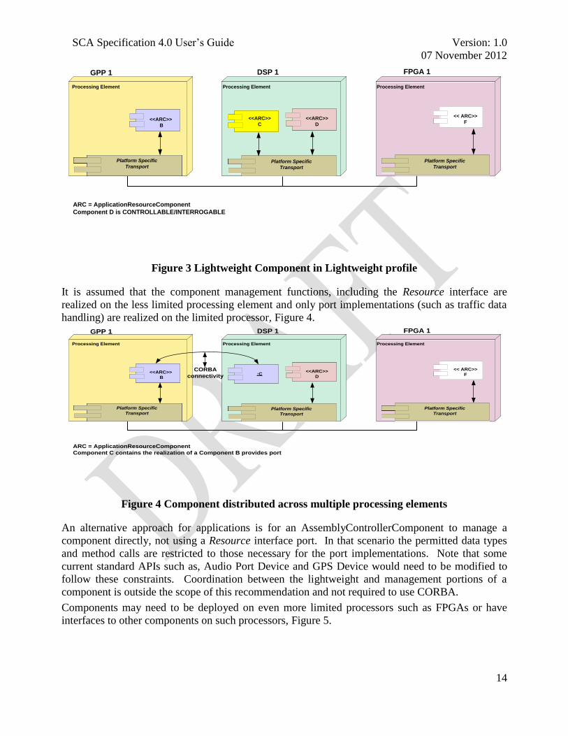
It is assumed that the component management functions, including the Resource interface are
realized on the less limited processing element and only port implementations (such as traffic data
handling) are realized on the limited processor, Figure 4.
Processing Element MHAL Computational Element MHAL Computational ElementProcessing Element
GPP 1 DSP 1 FPGA 1
Platform -Specifi
cTransportPlatform -
Specifi
cTransportPlatform -
Specifi
cTransportPlatform -
Specifi
cTransportPlatform -
Specifi
cTransport
Platform Specific
Transport Platform -Specifi
cTransportPlatform -
Specifi
cTransportPlatform -
Specifi
cTransportPlatform -
Specifi
cTransportPlatform -
Specifi
cTransport
Platform Specific
TransportPlatform -
Specifi
cTransportPlatform -
Specifi
cTransportPlatform -
Specifi
cTransportPlatform -
Specifi
cTransportPlatform -
Specifi
cTransport
Platform Specific
Transport
:C<<ARC>>
D<<ARC>>
B
Processing Element Processing Element
<< ARC>>
F
ARC = ApplicationResourceComponent
Component C contains the realization of a Component B provides port
CORBA
connectivity
Figure 4 Component distributed across multiple processing elements
An alternative approach for applications is for an AssemblyControllerComponent to manage a
component directly, not using a Resource interface port. In that scenario the permitted data types
and method calls are restricted to those necessary for the port implementations. Note that some
current standard APIs such as, Audio Port Device and GPS Device would need to be modified to
follow these constraints. Coordination between the lightweight and management portions of a
component is outside the scope of this recommendation and not required to use CORBA.
Components may need to be deployed on even more limited processors such as FPGAs or have
interfaces to other components on such processors, Figure 5.

SCA Specification 4.0 User‘s Guide Version: 1.0
07 November 2012
15
Processing Element MHAL Computational Element MHAL Computational ElementProcessing Element
GPP 1 DSP 1 FPGA 1
Platform -Specifi
cTransportPlatform -
Specifi
cTransportPlatform -
Specifi
cTransportPlatform -
Specifi
cTransportPlatform -
Specifi
cTransport
Platform Specific
Transport Platform -Specifi
cTransportPlatform -
Specifi
cTransportPlatform -
Specifi
cTransportPlatform -
Specifi
cTransportPlatform -
Specifi
cTransport
Platform Specific
TransportPlatform -
Specifi
cTransportPlatform -
Specifi
cTransportPlatform -
Specifi
cTransportPlatform -
Specifi
cTransportPlatform -
Specifi
cTransport
Platform Specific
Transport
<<ARC>>
C
<<ARC>>
D<<ARC>>
B
Processing Element Processing Element
:F
ARC = ApplicationResourceComponent
Component F contains the realization of a Component B provides port
Component F also has additional restrictions on it’s data types
CORBA
connectivity
Figure 5 Distributed component with FPGA portion
Compatibility will be enhanced in these instances if data types are restricted to those realizable on
such processors. Therefore, components implementing the lightweight profile are encouraged to
avoid using the data types discouraged in the Permitted Data Types Section and marked with * in
the table of Attachment 1 to Appendix E-1 (see reference [4]).
3.1.4 Guidance on restriction interface data types
It is recommended that data types be restricted in any interface to modules implemented on
extremely limited processing elements such as FPGAs and most DSPs.
Interfaces to code modules implemented on extremely limited processing elements, such as
FPGAs and most DSPs, whether or not they are implemented in CORBA, are encouraged to refrain
from using the data types marked with * in the Lightweight CORBA profile.
This recommendation is intended to enhance portability of CORBA to non-CORBA
implementations and to ensure that data can be exchanged easily between CORBA and non-
CORBA components.
3.1.5 Rationale for CORBA feature inclusion in the profiles
The choice to include CORBA features in the profiles was driven by use cases. Some of these use
cases are listed along with columns comparing Full with minimumCORBA and CORBA/e
Compact in Attachment 1 to Appendix E-1 (see reference [4]).
3.2 PUSH MODEL
3.2.1 Overview
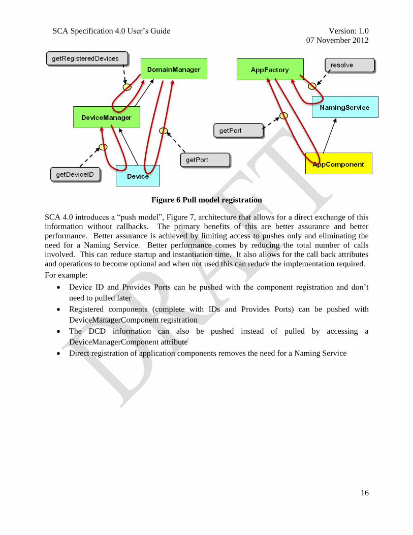
Prior versions of the SCA have been ―pull model‖ oriented as shown in Figure 6. References are
exchanged, but to get the information that‘s really needed, callbacks need to be made.
For example:
getPort for pulling uses and provides ports
Pulling attributes (e.g. deviceID, registeredDevices)
Pulling Application Components from a Naming Service
SCA Specification 4.0 User‘s Guide Version: 1.0
07 November 2012
16
Figure 6 Pull model registration
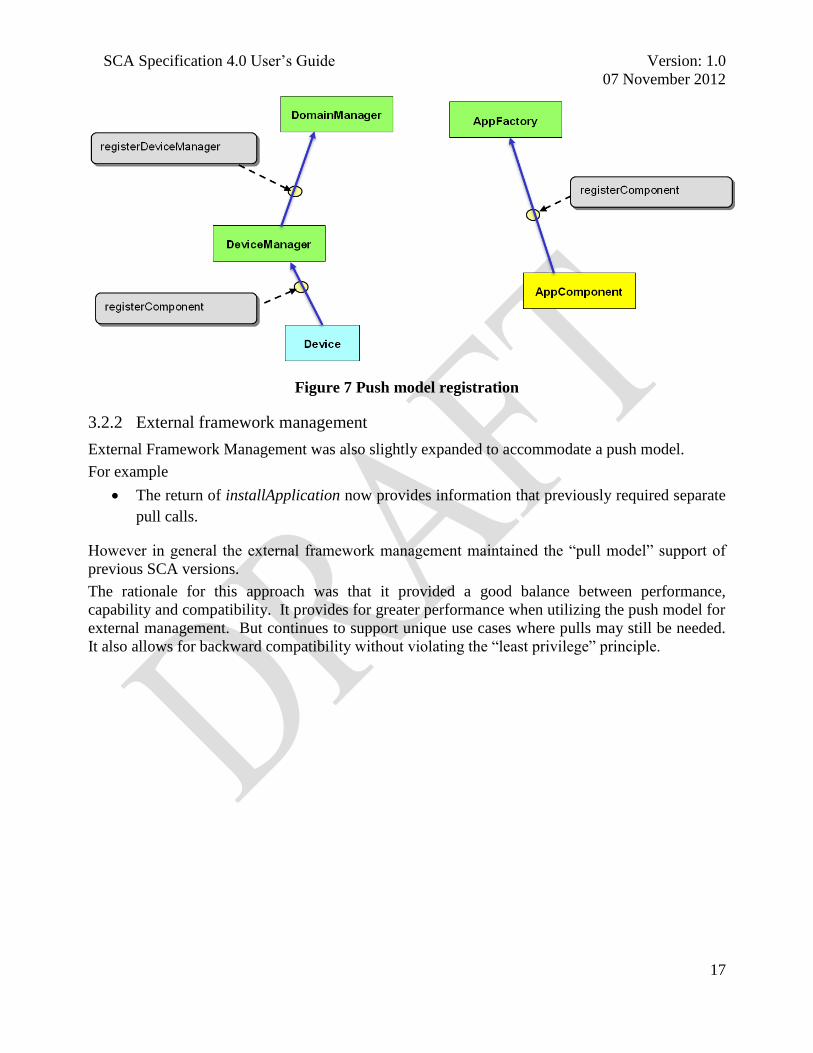
SCA 4.0 introduces a ―push model‖, Figure 7, architecture that allows for a direct exchange of this
information without callbacks. The primary benefits of this are better assurance and better
performance. Better assurance is achieved by limiting access to pushes only and eliminating the
need for a Naming Service. Better performance comes by reducing the total number of calls
involved. This can reduce startup and instantiation time. It also allows for the call back attributes
and operations to become optional and when not used this can reduce the implementation required.
For example:
Device ID and Provides Ports can be pushed with the component registration and don‘t
need to pulled later
Registered components (complete with IDs and Provides Ports) can be pushed with
DeviceManagerComponent registration
The DCD information can also be pushed instead of pulled by accessing a
DeviceManagerComponent attribute
Direct registration of application components removes the need for a Naming Service
SCA Specification 4.0 User‘s Guide Version: 1.0
07 November 2012
17
Figure 7 Push model registration
3.2.2 External framework management
External Framework Management was also slightly expanded to accommodate a push model.
For example
The return of installApplication now provides information that previously required separate
pull calls.
However in general the external framework management maintained the ―pull model‖ support of
previous SCA versions.
The rationale for this approach was that it provided a good balance between performance,
capability and compatibility. It provides for greater performance when utilizing the push model for
external management. But continues to support unique use cases where pulls may still be needed.
It also allows for backward compatibility without violating the ―least privilege‖ principle.

SCA Specification 4.0 User‘s Guide Version: 1.0
07 November 2012
18
Figure 8 External framework management
3.2.3 Registered and obtainable provides ports
In order to implement a ―push model‖ and allow continued support of all prior use cases, the
provides port semantics had to be enriched. SCA 4.0 provides for two types of provides ports,
termed ―Registered‖ and ―Obtainable‖. Sometime these are referred to using names found in
previous versions draft versions ―Static‖ and ―Dynamic‖. To avoid confusion, Registered Provides
ports = Static Provides Ports. Obtainable Provides Ports = Dynamic Provides Ports.
3.2.3.1 Registered provides ports
Registered provides ports are provides ports which have a lifecycle tied to the lifecycle of the
component. Registered ports are registered with the framework during component registration and
the framework will not attempt to retrieve them when making connections. Registered ports are
not explicitly released by the framework except through the component‘s releaseObject operation.
This means a component can expect getProvidesPorts and disconnectPorts to not typically be
called for the provides ports it registered. In some cases, for assurance reasons, a component may
want to explicitly reject calls for these ports (e.g. raise an UnknownPort or InvalidPort exception).
In some cases, a component may want to allow ports that are ―registered‖ to still also be
―obtainable‖. Meaning the ports can be retrieved from getProvidesPorts and then connections to
the ports can be disconnected through disconnectPorts. It is left unspecified to allow the
component developer to customize this behavior to match the needs of the target platform.
However a framework that is built strictly to the specified requirements will not retrieve registered
provides ports through getProvidesPorts and will not disconnect connections to them through
disconnectPorts.

SCA Specification 4.0 User‘s Guide Version: 1.0
07 November 2012
19
Figure 9 Registered port management
3.2.3.2 Obtainable provides ports
Registered provides ports are provides ports which are meant to have a lifecycle tied to the
lifecycle of a given connection. Obtainable provides ports are not registered with the component
and instead the framework will attempt to retrieve the ports through getProvidesPorts when they‘re
needed to complete connections. Obtainable provides ports are explicitly released by the
Framework via disconnectPorts when the connections to them are torn down. With obtainable
provides ports, by specifying connectionIDs on getProvidesPorts and calling disconnectPorts,
additional use cases and added functionality are supported that is not available within prior SCA
versions.
Figure 10 Obtainable port management

SCA Specification 4.0 User‘s Guide Version: 1.0
07 November 2012
20
It is not specified that obtainable provides ports have to be tied to the lifecycle of a given
connection. Several use cases exist where it may have a longer lifecycle:
A ―backward compatibility‖ use case where a provides port that is still created and released
with the component, but simply not registered, mimicking more of the prior SCA pull-
model behavior
A ―fan in‖ use case where the same provides port instance is utilized to service multiple
connections, with reference counting used to dictate when it is finally released.
Figure 11 Port lifecycles
3.3 ENHANCED APPLICATION CONNECTIVITY
3.3.1 Background
Prior to the release of SCA 4.0, the SCA only supported the ability to deploy individual, standalone
applications. While multiple applications could be deployed on a platform, the SCA component
framework provided no direct support to interconnect or logically nest these applications. As a
result, the client creating the applications was left to do this manually, using a combination of
external ports and either ―hard coded‖ interconnection or automatic interconnection, using
information gleaned from the application XML.
SCA Specification 4.0 User‘s Guide Version: 1.0
07 November 2012
21
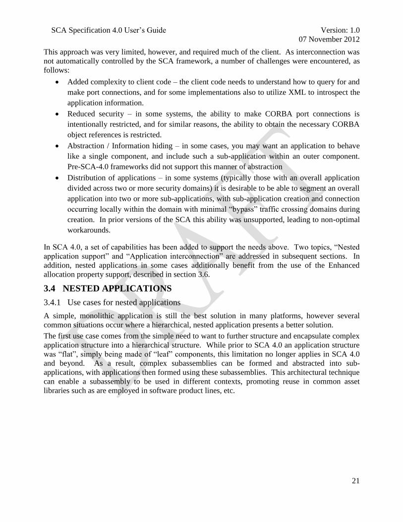
This approach was very limited, however, and required much of the client. As interconnection was
not automatically controlled by the SCA framework, a number of challenges were encountered, as
follows:
Added complexity to client code – the client code needs to understand how to query for and
make port connections, and for some implementations also to utilize XML to introspect the
application information.
Reduced security – in some systems, the ability to make CORBA port connections is
intentionally restricted, and for similar reasons, the ability to obtain the necessary CORBA
object references is restricted.
Abstraction / Information hiding – in some cases, you may want an application to behave
like a single component, and include such a sub-application within an outer component.
Pre-SCA-4.0 frameworks did not support this manner of abstraction
Distribution of applications – in some systems (typically those with an overall application
divided across two or more security domains) it is desirable to be able to segment an overall
application into two or more sub-applications, with sub-application creation and connection
occurring locally within the domain with minimal ―bypass‖ traffic crossing domains during
creation. In prior versions of the SCA this ability was unsupported, leading to non-optimal
workarounds.
In SCA 4.0, a set of capabilities has been added to support the needs above. Two topics, ―Nested
application support‖ and ―Application interconnection‖ are addressed in subsequent sections. In
addition, nested applications in some cases additionally benefit from the use of the Enhanced
allocation property support, described in section 3.6.
3.4 NESTED APPLICATIONS
3.4.1 Use cases for nested applications
A simple, monolithic application is still the best solution in many platforms, however several
common situations occur where a hierarchical, nested application presents a better solution.
The first use case comes from the simple need to want to further structure and encapsulate complex
application structure into a hierarchical structure. While prior to SCA 4.0 an application structure
was ―flat‖, simply being made of ―leaf‖ components, this limitation no longer applies in SCA 4.0
and beyond. As a result, complex subassemblies can be formed and abstracted into sub-
applications, with applications then formed using these subassemblies. This architectural technique
can enable a subassembly to be used in different contexts, promoting reuse in common asset
libraries such as are employed in software product lines, etc.

SCA Specification 4.0 User‘s Guide Version: 1.0
07 November 2012
22
ApplicationManager
<<Application
Resource>>
AppComponent B
<<Assembly Controller>>
SubAssembly C1
<<Application
Resource>>
AppComponent D
<<Application
Resource>>
Component C4
<<Application
Resource>>
Component C3
<<Application
Resource>>
Component C2
<<Assembly Controller>>
AppComponent A
Figure 12 Simple nested application
An example of this structuring is shown in Figure 12. In this example, an overall application is
made up of four top-level components, with one of the components (AppComponent A) also
functioning as the application‘s AssemblyControllerComponent. Component C1 however is not a
simple component created by the normal componentinstantiation in the SAD1, but rather a
subapplication created through an assemblyinstantiation. To AppComponentA this nested sub-
application is abstracted to a single CF::Resource interface, but from a creational standpoint the
―upper level‖ ApplicationFactoryComponent constructs a true sub-application per a cited SAD file.
As is discussed later, in this example there is no separate ApplicationManagerComponent produced
to manage the sub-application, rather the management all being done by the upper blue
ApplicationManagerComponent. This is a core framework implementation decision, however. An
equally valid approach would be for the sub-application to be managed by an intermediate
ApplicationManagerComponent, with only the CF::Resource narrowed interface made available to
AppComponent A.
A second compelling use-case arises on platforms which provide encryption in such a way that two
or more security domains are established (e.g. plaintext and ciphertext domains). In some high
assurance environments, these domains are distinct and separated (usually by some sort of
cryptographic subsystem) such that control and configuration communications between the
domains need to be minimized. In such a system, it could be beneficial to structure an application
such that it resembles two or more sub-applications, one in each security domain. A typical
representation of this situation is shown in Figure 13.
1 Componentplacements are located inside either a componentplacement or hostcollocation element

SCA Specification 4.0 User‘s Guide Version: 1.0
07 November 2012
23
CT Sub-applicationPT Sub-application
ApplicationManager
<<Assembly Controller>>
PtComponent 1
<<Application
Resource>>
PtComponent 2
<<Assembly Controller>>
CtComponent 1
<<Application
Resource>>
PtComponent 3
<<Application
Resource>>
CtComponent 4
<<Application
Resource>>
CtComponent 3
<<Application
Resource>>
CtComponent 2
Figure 13 Security domain divided application
In this example, we see a top-level application wholly consisting of two sub-applications, each
deployed in a different security domain2. In this example the option of having an Application
ManagerComponent3 distribute properties and control to two distinct
AssemblyControllerComponents is also employed. Also note that how this application gets
physically constructed is not fully specified in the SCA – a clever implementation could split the
required CF::ApplicationFactory behavior across the security domains as well (while still
controlling this through a common CF::ApplicationFactory interface, minimizing cross-domain
communications.
3.4.2 How nested applications work in the SCA 4.0
While a significant enhancement, support of nested applications in SCA 4.0 is not immediately
obvious, or described in a dedicated section. Instead, such support is ―enabled‖ through a number
of small changes in scattered requirements. The major areas of change supporting this feature are
listed in Section 3.1.3.3.1 (Application), 3.1.3.3.3 (ApplicationFactory), and in several parts of
Appendix D.
3.4.2.1 ApplicationFactoryComponent support for nested applications
In the big picture, an ApplicationFactoryComponent (as fronted by the ApplicationFactory
interface) provides the means to create, from a client‘s standpoint, a single, top-level application.
This application is created according to the specifications set out in a set of XML files, culminating
in the Software Assembly Descriptor (SAD), which defines how the application is created. These
SAD instructions include which elements are used, how they are deployed, configured, and how
they are connected. In earlier SCA version, elements always referred to individual components,
which were in turn defined by Software Component Descriptors (SCD) and so on.
2 Not to be confused with an SCA domain – in this system, there is still only one domain manager.
3 Application ManagerComponents implement the CF::Application interface and responsibilities,
and are created / supplied by the core framework.
SCA Specification 4.0 User‘s Guide Version: 1.0
07 November 2012
24
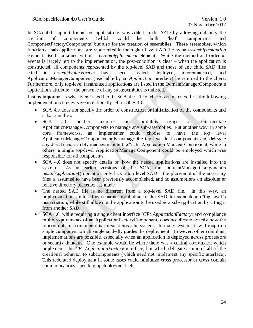
In SCA 4.0, support for nested applications was added in the SAD by allowing not only the
creation of components (which could be both ―leaf‖ components and
ComponentFactoryComponents) but also for the creation of assemblies. These assemblies, which
function as sub-applications, are represented in the higher-level SAD file by an assemblyinstantion
element, itself contained within a assemblyplacement element. While the method and order of
events is largely left to the implementation, the post-condition is clear – when the application is
constructed, all components represented by the top-level SAD and those of any child SAD files
cited in assemblyplacements have been created, deployed, interconnected, and
ApplicationManagerComponent (reachable by an Application interface) be returned to the client.
Furthermore, only top-level instantiated applications are listed in the DomainManagerComponent‘s
applications attribute – the presence of any subassemblies is unlisted.
Just as important is what is not specified in SCA 4.0. Though not an inclusive list, the following
implementation choices were intentionally left in SCA 4.0:
SCA 4.0 does not specify the order of construction or initialization of the components and
subassemblies.
SCA 4.0 neither requires nor prohibits usage of intermediate
ApplicationManagerComponents to manage any sub-assemblies. Put another way, in some
core frameworks, an implementer could choose to have the top level
ApplicationManagerComponent only manage the top level leaf components and delegate
any direct subassembly management to the ―sub‖ Application ManagerComponent, while in
others, a single top-level ApplicationManagerComponent could be employed which was
responsible for all components.
SCA 4.0 does not specify details on how the nested applications are installed into the
system. As in earlier versions of the SCA, the DomainManagerComponent‘s
installApplication() operation only lists a top level SAD – the placement of the necessary
files is assumed to have been previously accomplished, and no assumptions on absolute or
relative directory placement is made.
The nested SAD file is no different from a top-level SAD file. In this way, an
implementation could allow separate installation of the SAD for standalone (―top level‖)
instantiation, while still allowing the application to be used as a sub-application by citing it
from another SAD.
SCA 4.0, while requiring a single client interface (CF::ApplicationFactory) and compliance
to the requirements of an ApplicationFactoryComponent, does not dictate exactly how the
function of this component is spread across the system. In many systems it will map to a
single component which singlehandedly guides the deployment. However, other compliant
implementations are possible, especially when an application is deployed across processors
or security domains. One example would be where there was a central coordinator which
implements the CF::ApplicationFactory interface, but which delegates some of all of the
creational behavior to subcomponents (which need not implement any specific interface).
This federated deployment in some cases could minimize cross processor or cross domain
communications, speeding up deployment, etc.

SCA Specification 4.0 User‘s Guide Version: 1.0
07 November 2012
25
3.4.2.2 ApplicationManagerComponent support for nested applications
The ApplicationManagerComponent4 has two broad responsibilities, which were expanded with
the introduction of nested applications within SCA 4.0. The first responsibility is to tear down the
application instance that was created by the corresponding ApplicationFactoryComponent, and
from a postcondition standpoint this behavior remains the same in SCA 4.0. When nested
applications are supported in SCA 4.0, the allocation of the teardown responsibilities is
unspecified. One common implementation would be for the top level
ApplicationManagerComponent to only manage top level components, with one of those
―components‖ itself being a distinct ApplicationManagerComponent which manages its
subapplication components. The advantage of this approach is one of symmetry (―each SAD
creates an application and is managed by an ApplicationManagerComponent‖) and greatest
similarity to prior SCA core framework implementations. Other implementations are valid,
however. For example, SCA 4.0 does not require ApplicationManagerComponents to manage the
sub-application components – instead a single, top-level ApplicatoinManagerComponent could be
responsible for teardown of all components (and port disconnection, etc.). This approach in some
cases may be more efficient or centralize the domain data.
ApplicationManagerComponents are also responsible for distributing client calls made through the
CF::Resource interface (which is specialized by the CF::Application interface) to the application.
In versions prior to SCA4.0, distribution was straightforward, as all calls were to be passed to a
single CF::Resource supporting component (not an assembly) that was designated as the
assemblycontroller in the SAD. If the DMD accardinality attribute has a value of ―single‖, the
conventions of only one designated assemblycontroller, which is itself a component, and the
ApplicationManagerComponent responsibilities remain the same.
However in implementations that implement the NestedDeployment UOF and have a DMD
accardinality attribute with a value of ―multiple‖, multiple assemblycontrollers are allowed and
those assemblycontrollers are allowed to refer to an assemblyinstantiation. When this is the case,
the ApplicationManagerComponent is no longer able to blindly forward configure(), query() and
runTest() as it did before. Instead, it must examine each individual property and test, and forward
it to only the appropriate assemblycontrollers based on the information contained in the top level
SAD and derived XML files of the application (which in the nested case would include at least one
additional SAD). Additionally, as multiple properties can be listed in a configure or query call, the
ApplicationManagerComponent may also be required to break up configure and query calls, as
well as potentially combine their results and exception behavior.
3.5 APPLICATION INTERCONNECTION
3.5.1 Overview
An alternative to having a simple, monolithic application would be to have multiple independent
applications that collaborate with one another. The SCA 4.0 application interconnection capability
provides a uniform approach to address the problem of how to establish connections between
framework components modeled as applications. Prior to the introduction of this capability there
were multiple solutions regarding how this problem should be addressed which complicated
4 Prior to SCA 4.0, there was no formal ApplicationManagerComponent, instead all requirements
were allocated to an unnamed CF component which implemented in the CF::Application interface.

SCA Specification 4.0 User‘s Guide Version: 1.0
07 November 2012
26
software reuse and portability. The introduction of this capability should alleviate those problems
and ensure that a realization of this approach is available across platforms.
3.5.2 Use case for interconnecting applications
An alternative to having a simple, monolithic application would be to have multiple independent
applications that need to collaborate with one another. A use case which highlights the need for this
capability would be one that would reinforce the separation of concerns and loose coupling of a
well architected system. For example, a radio platform might have an associated android
presentation layer that provided an implementation of a general purpose user interface that could be
used to manage and monitor the system. In this scenario the system could have been designed and
implemented in accordance with the Model, View, Presenter pattern where the applications to be
connected would have be the waveform (Model) and UI intermediary (Presenter).
Earlier SCA versions did not have a means to form these connections. Their SAD contained the
externalports element which by definition provided a means for a component (application or
otherwise) external a waveform to be connected to an application, but no framework construct
existed to establish those connections. Typically the gap was filled by introducing an additional
component within the system that had the responsibility for connection establishment.
3.5.3 Application interconnection design
SCA 4.0 defines a formal mechanism to utilize the externalports element as the conduit through
which the framework is able to manage the formation and destruction of those inter-application
connections. The external port connection construct provides a good solution for this problem
because of the nature of the problem – the two applications that need to be connected have a
dependency on one another for the connection to be created but they are created independently and
there are no guarantees that they will be created together. The connection mechanism needs to
know how to accommodate instances when one side of the connection exists and the other does
not. However, if both sides of the applications are created then the applications are always
connected.
SCA Specification 4.0 User‘s Guide Version: 1.0
07 November 2012
27
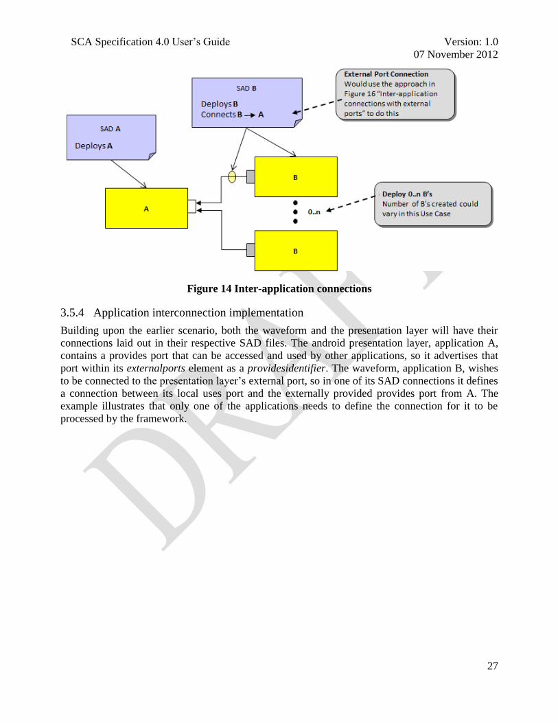
Figure 14 Inter-application connections
3.5.4 Application interconnection implementation
Building upon the earlier scenario, both the waveform and the presentation layer will have their
connections laid out in their respective SAD files. The android presentation layer, application A,
contains a provides port that can be accessed and used by other applications, so it advertises that
port within its externalports element as a providesidentifier. The waveform, application B, wishes
to be connected to the presentation layer‘s external port, so in one of its SAD connections it defines
a connection between its local uses port and the externally provided provides port from A. The
example illustrates that only one of the applications needs to define the connection for it to be
processed by the framework.

SCA Specification 4.0 User‘s Guide Version: 1.0
07 November 2012
28
Figure 15 Connectivity specific example
3.5.5 ApplicationFactoryComponent support for interconnected applications
The specification introduces a new type, application, to the domainfinder element. The semantics
associated with this type provide instructions to the framework regarding which elements are to be
involved within the connection and how it should be formed. The ApplicationFactoryComponent
retrieves the connection endpoint via the domain‘s domainfinder element. When the application
type is used, no implicit creation behavior is intended, so if one of the application endpoints does
not exist, the framework is not expected to instantiate the missing application. If neither endpoint
can be resolved, then the specification allows for an implementation specific behavior - although
the desired approach would be for the connection to be held in a pending state until it can be made
(note that in this approach either the waveform or the framework will need to have sufficient
safeguards in place to insure that a call to this connection does not result in an unexpected or
uncontrolled termination). An alternative solution would be to prevent the application from being
created, although this seems to as if it would be excessive because the waveform should have been
built such that there was not a critical dependency between the applications.

SCA Specification 4.0 User‘s Guide Version: 1.0
07 November 2012
29
Figure 16 Inter-application connections with external ports
The domainfinder element allows for multiple connection strategies that the
ApplicationFactoryComponent must be able to accommodate depending on what information is
provided in the domain profile file. When only the application name is specified then any existing
ApplicationManagerComponent in the domain with that name can be used. When both the
application factory name and application name are specified, only the named
ApplicationManagerComponent created by the specified ApplicationFactoryComponent is
returned. When only the application factory name is specified then any
ApplicationManagerComponent created by the specified ApplicationFactoryComponent may be
used.
3.6 ENHANCED ALLOCATION PROPERTY SUPPORT
3.6.1 Overview
Several use cases exist that require the framework to have the ability to constrain the deployment of
application or nested application components. SCA 2.2.2 provided this capability with the
introduction of the SCA Extension and its channel deployment functionality. Those constructs were
not only included with the incorporation of the Extension within SCA 4.0, but comparable
capabilities were also added with the introduction of nested applications. The nested application
SCA 4.0 elements extend the SCA 2.2.2 SCA allocation properties to make them more dynamic
and accessible to nested applications. The new constructs provide users with the ability to deploy
nested applications to different domains as well as most of the other capabilities associate with
traditional allocation properties.

SCA Specification 4.0 User‘s Guide Version: 1.0
07 November 2012
30
3.6.2 Descriptor structure for nested applications
The SAD file composition was modified in SCA 4.0 to accommodate nested applications. An SCA
4.0 application consists of 0 or more components and 0 or more nested applications. The nested
applications incorporate a new element, applicationinstantiation, which is similar to a
componentinstantiation, although it has different sub-elements.
Nested applications are similar to an ApplicationResourceComponent in that they can receive
properties, deviceassignments and deploymentdependencies. However they differ from those
components in that they cannot be created by a ComponentFactoryComponent. The information in
the applicationinstantiation element is intentionally similar to the ApplicationFactory::create()
call. This similarity permits an implementation to use the ApplicationFactory::create() operation to
create a nested application.
<!ATTLIST componentfile
id ID #REQUIRED
type CDATA #IMPLIED>
<!ELEMENT partitioning
( componentplacement | hostcollocation
| assemblyinstantiation)
)+>
<!ELEMENT assemblyplacement
( componentfileref
, assemblyinstantiation+
)>
<!ELEMENT assemblyinstantiation
( usagename?
, componentproperties? ,
, deviceassignments?,
, deploymentdependencies?
) >
<!ATTLIST assemblyinstantiation
id ID #REQUIRED>
3.6.3 Enhanced Allocation Properties in SCA 4.0
SCA 2.2.2 allocation properties could only be set in .prf files, and not overridden. Similarly,
dependencies were specified in .spd files, and could not be overridden. This severely limited the
manner in which they may be used.
The SCA deploys components by evaluating dependency requirements against existing component
allocation property definition. As an example a DeviceComponent (or other component) defines an
allocation property in a .prf file as follows:
Type can now be ―software package
descriptor‖ or ―software assembly
descriptor‖
Assemblies may consist of both
components and assemblies (e.g.
SAD). However, assemblies
cannot be inside hostcollocaton
sections and cannot be created
by component factories.
New element, modeled after
componentinstantiation.
Componentproperties (configureproperty type
only), override nested SAD similar to that in
create call. and deviceassignements and
deploymentdependencies act in the same way
as if passed into ApplicationFactory::create().
Nested assemblies can also serve as
assemblycontrollers (via their CF::Resource
/ CF::Application interface)

SCA Specification 4.0 User‘s Guide Version: 1.0
07 November 2012
31
<simple id="RadioChannel" type="short" name="RadioChannel">
<value>0</value>
<kind kindtype="allocation"/>
<action type=“eq"/>
</simple>
Then a component to be deployed establishes a dependency against the allocation property by
stating the type of device it requires:
<dependency type="RadioChannelDependency">
<propertyref refid= "RadioChannel" value="5"/>
</dependency>
If the dependency can be satisfied by one of the component allocation property definitions within
the domain, then that DeviceComponent becomes a usage or deployment candidate.
SCA 4.0 provides the ability to override component allocation properties in the
componentinstantiation section. This allows a system designer to assign different values to
allocation properties on a per-instance basis, e.g. ―the channel 4 instance of the GppDevice gets the
deployedChannel allocation property overridden to 4‖. In prior SCA versions, a system designer
would have had to edit the component‘s .prf file or use the SCA extension .pdd file to accomplish
this. SCA 4.0 also introduces the capability to specify SAD and create() based
deploymentdependencies. The deploymentdependencies element specifies a list of dependencies
which can override SPD defined dependencies (either within deployment or as part of a uses device
connection). The dependency relationship is overridden, not the allocation property, which differs
from other ―property overrides‖. Lastly, a list of deploymentdependencies can be passed into the
ApplicationFactory::create() operation to allow client-controlled dependencies (e.g. radio channel)
to be specified.
3.6.4 Dependency Hierarchies in SCA 4.0
SPDs define the dependencies for a particular component type unless overridden, these apply to all
instances of the component.
As shown in Figure 17, SAD componentinstantiations can optionally override a dependency for a
given instance – if the SPD uses the dependency for deployment or usesdevice relationships. This
would, for example allow an application to place two instances of the same component in different
domains.
An optional top-level SAD deploymentdependencies element allows for global dependency
overriding across all applicable application components (see Figure 17). Using this approach does
not impose the dependency on a component, but overrides it as if a like-named dependency existed
within the component‘s SPD. This approach is likely more applicable within an assembly that uses
nested applications.

SCA Specification 4.0 User‘s Guide Version: 1.0
07 November 2012
32
Figure 17 Dependency Hierarchy
At the highest level of the dependency hierarchy, a client can optionally supply
deploymentdependencies which could be applied to the entire application. A common usage
scenario would be to specify a radio channel placement dependency. As Figure 18 depicts, when
application nesting is used, the rules stay the same but overriding occurs from the outermost SAD
(highest precedence) to the innermost SAD. An additional deploymentdependency is added to the
assemblyinstantiation element. This allows dependencies to be supplied that would apply to that
nested application (and any of its children). A common usage scenario for this capability would be
to place distinct sub-applications in different domains.

SCA Specification 4.0 User‘s Guide Version: 1.0
07 November 2012
33
Figure 18 Dependency Hierarchy and Sub-Applications
The following table provides an example of a class of allocation properties and how they might be
used within a system:
Figure 19 Allocation property examples

SCA Specification 4.0 User‘s Guide Version: 1.0
07 November 2012
34
3.7 SCA WAVEFORM CONSTRUCTION
3.7.1 Overview
The SCA component structure contains a collection of building blocks that a product developer can
combine in order to produce a deliverable, e.g. a waveform or service implementation. The process
of creating an end product requires a series of engineering decisions, which from an SCA
perspective are centered on decomposing the overall product functionality into encapsulated
elements that can be integrated with the defined SCA components.
3.7.2 FM3TR waveform example
The publicly available FM3TR waveform architecture is illustrated in Figure 20 (this waveform is
available from the JTRS Open Source Information Repository [13]). The yellow-colored
components represent radio set functionality, whereas the red and blue colored blocks represent
waveform software components.
SCA contains component definitions that should be used for each macro-sized component. Any of
the macro-sized waveform components, for example the Data Link Control (DLC) component,
could be implemented by aggregating several smaller modules or routines, but those routines would
be bundled and it would only expose functionality to external users via a consolidated set of
interfaces.
SCA utilizes a ―port‖ construct as the mechanism by which a component may be extended to
provide application specific functionality and behavior. The blue and red
ApplicationResourceComponents on the GPP expose: in, out, and control ports. The core
framework can connect the port interfaces to other ApplicationComponents or
PlatformComponents in order to provide overall waveform functionality. Generally, the ‗in‘ ports
are described as ‗provides‘ ports, whereas the ‗out‘ ports are ‗uses‘ ports, because they either
provide or use port connections, respectively.
Using either the middleware services provided by the radio set, or direct C++ pointers, connection
IDs and object references permit independent software components to communicate. The
components only need each other‘s pointer or object reference. The messaging becomes more
difficult if the components are distributed into separate memory partitions. For such deployments,
middleware services allow a general solution to be applied throughout the complete radio set.

SCA Specification 4.0 User‘s Guide Version: 1.0
07 November 2012
35
Figure 20 Example FM3TR SCA Waveform Design
The FM3TR waveform is a simple time domain multiplexed access (TDMA) application with
Continuous Phase Frequency Shift Keying (CPFSK) as the baseband modulation. The JTRS
implementation provides either data or voice operation. Continuously Variable-Slope Delta
modulation (CVSD) is implemented for the vocoder. Reed-Solomon (R-S) forward error coding is
used to improve the bit reliability of the wireless link.
The Data Multiple Access Control (MAC) is an SCA ApplicationResourceComponent that
converts the input data stream into data symbols grouped to match the R-S coding format. The
voice MAC performs a similar operation for the data stream produced by the vocoder. The A-code
is a simple 32-bit synchronization code used to synchronize transmitter and receiver. The S-code is
a second synchronization word used to identify data packet types such as voice, data, etc.
The architecture and deployment of this waveform is fairly typical for SCA implementations,
although other variations are possible. In this example, the waveform components deployed on the
FPGA and DSP do not have SCA interfaces. Historically radio architects have attempted to wring
the last drop of performance from the DSP and FPGA devices and not implemented SCA interfaces
on these lower-level software components. There is a substantial cost for this strategy – a loss of
portability for these waveform components. However, advances have made extending the full SCA
model beyond the bounds of the GPP much more technically feasible.
An example logical model of an FM3TR radio is illustrated in Figure 21, complete with radio
devices, services, and core framework components.

SCA Specification 4.0 User‘s Guide Version: 1.0
07 November 2012
36
Figure 21 Example Deployment of FM3TR
3.8 RESOURCE AND DEVICE INTERFACE DECOMPOSITION
3.8.1 Overview
SCA 4.0 reworked the composition of the resource and device interfaces as a component of the
other changes that occurred within the specification. Two primary changes occurred; the first of
which removed the inheritance relationship between the Resource, Device, LoadableDevice and
ExecutableDevice interfaces; the second created new lower level interfaces and shifted some of the
attribute and operation definitions to those new interfaces. The finer granularity of the SCA 4.0
interfaces provides the developer with the ability to create more secure and lighter weight
components. The net impact of the changes is that the content of the top level interfaces, e.g.
Resource, will be roughly identical to that of prior SCA versions; however trivial modification will
need to be executed within the implementations to accommodate the new structure. The requisite
changes should be straightforward and oriented toward moving code around or changing the format
of an operation invocation and not introducing new logic. This illustrates the change in the
interface inheritance relationships from the perspective of the ExecutableDevice interface.

SCA Specification 4.0 User‘s Guide Version: 1.0
07 November 2012
37
Figure 22 ExecutableDevice Interface Inheritance Relationship
3.8.2 Resource Related Modifications
3.8.2.1 Resource interface changes
The new structure of the Resource interface supports the SCA 4.0 optional inheritance pattern as
well as the least privilege pattern employed within the JTRS APIs. The changes transform the
interface into an empty shell that serves as a common, well known entry point for an interface user
to a component that realizes the interface. From the user‘s perspective, there is the assurance that
they will always interface with a CF::Resource and not a proprietary variant of the interface that
was tailored to obtain a specialized realization. The flexibility and power of the approach becomes
apparent when it is evaluated from the provider‘s perspective. Figure 23 highlights the Resource
interface changes. The Resource shell was created by moving the identifier attribute to the new
ComponentIdentifier interface and the start and stop operations to the ControllableComponent
interface, leaving nothing directly within a Resource.

SCA Specification 4.0 User‘s Guide Version: 1.0
07 November 2012
38
Figure 23 Resource Interface Refactoring
As seen in Figure 24, all of the inherited Resource interfaces, with the exception of LifeCycle, may
be optionally inherited by a realization of the Resource interface. Having the ability to
conditionally inherit these interfaces allows the interface realization to be tailored to a product
specific set of requirements. Eliminating unnecessary interfaces also increases the assurance level
of the created component because the implementation will not contain any ―dead‖ code and the
finer granularity interface definitions allow the developer to expose only the interfaces and
information that need to be provided externally.
Figure 24 Resource Interface Optional Interfaces

SCA Specification 4.0 User‘s Guide Version: 1.0
07 November 2012
39
3.8.2.2 ComponentFactory Interface Changes
The ComponentFactory, pictured in Figure 25, was also refactored. The ComponentFactory
interface modifications take advantage of optional inheritance in a manner similar to that applied to
the Resource interface, Figure 24, but it has two important distinctions. The shutdown operation
was removed from the interface in lieu of an approach that aligns its life cycle management with
the other CF interfaces, i.e. utilizing the LifeCycle interface. Secondly, the ComponentFactory
interface was not refactored as a shell because the cost of creating the new interface did not
outweigh the low likelihood that there would be component factory collocation within a process
space.
Figure 25 ResourceFactory Interface Refactoring
3.8.3 Device Related Modifications
3.8.3.1 Device and LoadableDevice interface changes
The Device, Figure 26, and LoadableDevice, Figure 28, interfaces were refactored such that they
no longer have an inheritance relationship with the Resource interface. Both interfaces utilize
optional inheritance in a manner similar to the Resource interface and have been refactored as
shells.
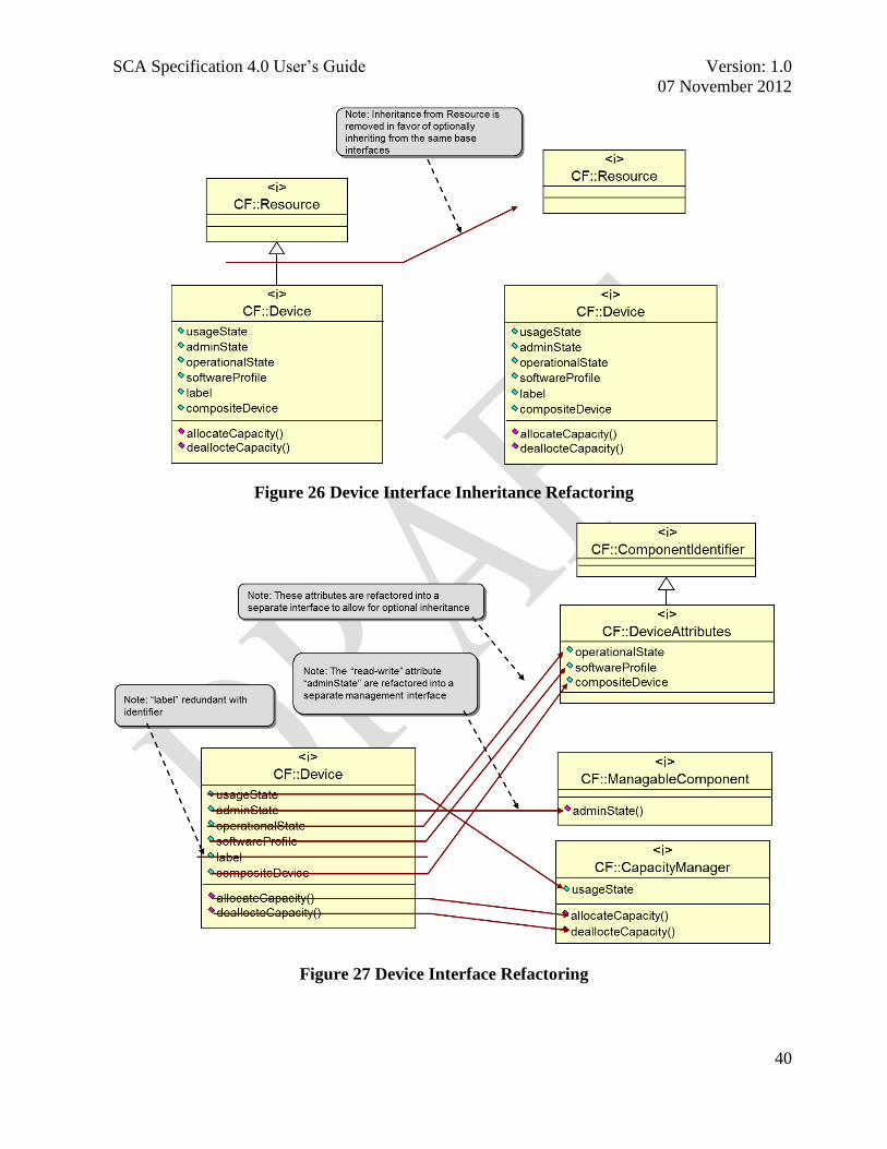
SCA Specification 4.0 User‘s Guide Version: 1.0
07 November 2012
40
Figure 26 Device Interface Inheritance Refactoring
Figure 27 Device Interface Refactoring

SCA Specification 4.0 User‘s Guide Version: 1.0
07 November 2012
41
Figure 28 LoadableDevice Interface Refactoring
3.8.3.2 ExecutableDevice Interface Changes
The ExecutableDevice interface, Figure 29, was refactored so that it no longer has an inheritance
relationship with the LoadableDevice interface however it was not converted to a shell interface.
Technically speaking, this interface should have been converted to be consistent with the other two
device interfaces, but it was not because the low probability of ExecutableDeviceComponent
collocation did not warrant incurring the cost associated with making the change.

SCA Specification 4.0 User‘s Guide Version: 1.0
07 November 2012
42
Figure 29 ExecutableDevice Interface Refactoring
3.8.4 Summary
The SCA 4.0 resource and device interfaces were refactored to remove many of the operations and
attributes from the top level interfaces and break the inheritance relationship between those
interfaces and the CF::Resource interface. The underlying rationale behind operation and attribute
removal is focused upon providing the developer with a mechanism to ―right size‖ their
components to the product requirements. Eliminating of the inheritance relationship allows the
components to circumvent the collocation prohibitions that are discussed in the Lightweight
Components section 3.11.
3.9 REFACTORED CF CONTROL AND REGISTRATION INTERFACES
3.9.1 Overview
SCA 4.0 reworked the composition of the control and registration interfaces as a component of the
other changes that occurred within the specification. The significant change that occurred was that
the interfaces were refactored into smaller, more concise, standalone interfaces. The composition of
these interfaces ensures that only the methods needed for management and registration are provided
to the consuming components. Having these prohibitions in place enhances the assurance profile of
the platform because it follows the least privilege pattern. The refactoring also improves platform
and system performance because it contains modifications that allow the SCA to be transformed
from a pull to a push model registration approach.

SCA Specification 4.0 User‘s Guide Version: 1.0
07 November 2012
43
3.9.2 DeviceManager Interface Changes
The DeviceManager registration operations, in Figure 30, were collapsed and migrated away from
the interface. The migration was consistent with the principles of the least privilege pattern in that
it is unnecessary for a client that already has a reference to a DeviceManagerComponent to require
an additional interface to provide the ability to register that component. The move takes advantage
of the fact that the only components required to register with a DeviceManagerComponent are
those that it launches, and it is a reasonable assumption to make that a DeviceManagerComponent
can provide a registration address as part of the launch parameters.
The registration process, which had been performed through an association between a
DeviceManagerComponent, DomainManagerComponent and ApplicationFactoryComponent, was
refined as part of the redesign. The SCA 4.0 design introduces a single capability that can be
associated with and used by any of those components. The behavior associated with this new
registry capability was reworked to leverage a push model mode of operations which yields
substantial performance improvements. Lastly, the registries take advantage of the fact that they are
able to provide a general purpose registration capability so that there is no longer a need to
distinguish between service, device or application component registration.
Figure 30 DeviceManager Interface Refactoring – registration operations
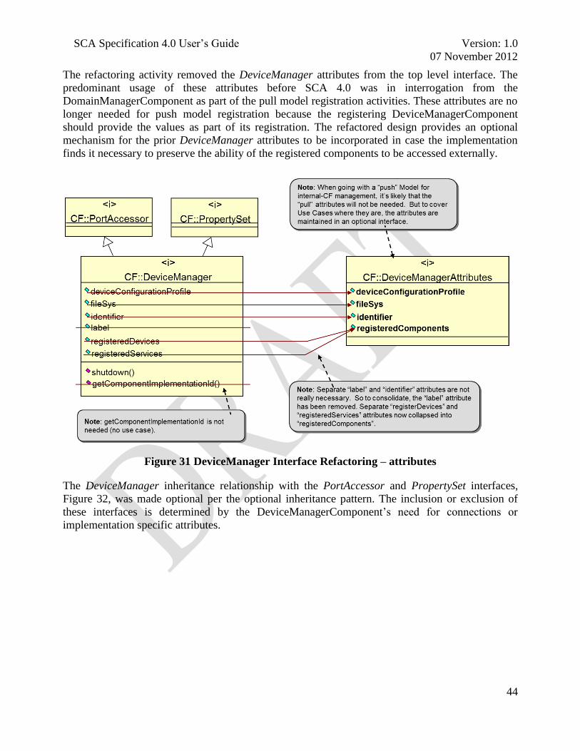
SCA Specification 4.0 User‘s Guide Version: 1.0
07 November 2012
44
The refactoring activity removed the DeviceManager attributes from the top level interface. The
predominant usage of these attributes before SCA 4.0 was in interrogation from the
DomainManagerComponent as part of the pull model registration activities. These attributes are no
longer needed for push model registration because the registering DeviceManagerComponent
should provide the values as part of its registration. The refactored design provides an optional
mechanism for the prior DeviceManager attributes to be incorporated in case the implementation
finds it necessary to preserve the ability of the registered components to be accessed externally.
Figure 31 DeviceManager Interface Refactoring – attributes
The DeviceManager inheritance relationship with the PortAccessor and PropertySet interfaces,
Figure 32, was made optional per the optional inheritance pattern. The inclusion or exclusion of
these interfaces is determined by the DeviceManagerComponent‘s need for connections or
implementation specific attributes.
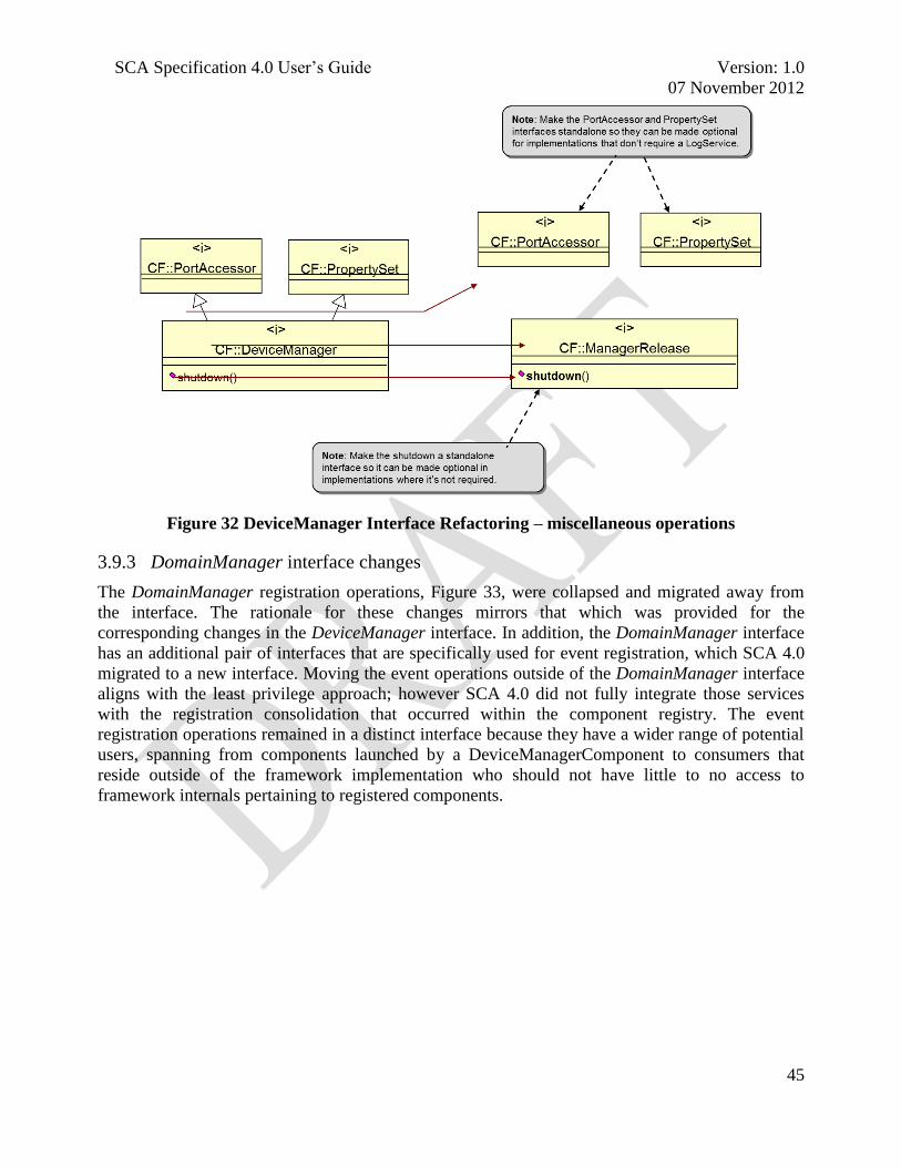
SCA Specification 4.0 User‘s Guide Version: 1.0
07 November 2012
45
Figure 32 DeviceManager Interface Refactoring – miscellaneous operations
3.9.3 DomainManager interface changes
The DomainManager registration operations, Figure 33, were collapsed and migrated away from
the interface. The rationale for these changes mirrors that which was provided for the
corresponding changes in the DeviceManager interface. In addition, the DomainManager interface
has an additional pair of interfaces that are specifically used for event registration, which SCA 4.0
migrated to a new interface. Moving the event operations outside of the DomainManager interface
aligns with the least privilege approach; however SCA 4.0 did not fully integrate those services
with the registration consolidation that occurred within the component registry. The event
registration operations remained in a distinct interface because they have a wider range of potential
users, spanning from components launched by a DeviceManagerComponent to consumers that
reside outside of the framework implementation who should not have little to no access to
framework internals pertaining to registered components.
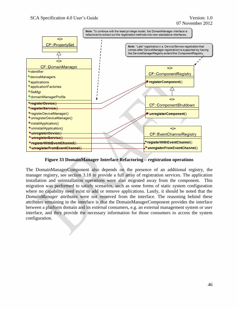
SCA Specification 4.0 User‘s Guide Version: 1.0
07 November 2012
46
Figure 33 DomainManager Interface Refactoring – registration operations
The DomainManagerComponent also depends on the presence of an additional registry, the
manager registry, see section 3.18 to provide a full array of registration services. The application
installation and uninstallation operations were also migrated away from the component. This
migration was performed to satisfy scenarios, such as some forms of static system configuration
where no capability need exist to add or remove applications. Lastly, it should be noted that the
DomainManager attributes were not removed from the interface. The reasoning behind these
attributes remaining in the interface is that the DomainManagerComponent provides the interface
between a platform domain and its external consumers, e.g. an external management system or user
interface, and they provide the necessary information for those consumers to access the system
configuration.

SCA Specification 4.0 User‘s Guide Version: 1.0
07 November 2012
47
Figure 34 DomainManager Interface Refactoring – manager registration operations
Figure 35 DomainManager Interface Refactoring – installation operations
3.9.4 Application Interface Changes
The Application interface, Figure 36, was refactored such that it provides the option to remove
client visibility of many of the interface attributes. These attributes provide a way for clients to
interrogate an application‘s run time internals. All of the information contained within these
attributes is essential for proper framework operations, however several scenarios exist for which it
is not needed by other clients. Moving the attributes to a separate interface and utilizing the
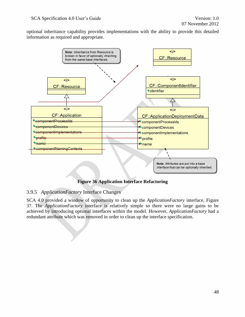
SCA Specification 4.0 User‘s Guide Version: 1.0
07 November 2012
48
optional inheritance capability provides implementations with the ability to provide this detailed
information as required and appropriate.
Figure 36 Application Interface Refactoring
3.9.5 ApplicationFactory Interface Changes
SCA 4.0 provided a window of opportunity to clean up the ApplicationFactory interface, Figure
37. The ApplicationFactory interface is relatively simple so there were no large gains to be
achieved by introducing optional interfaces within the model. However, ApplicationFactory had a
redundant attribute which was removed in order to clean up the interface specification.

SCA Specification 4.0 User‘s Guide Version: 1.0
07 November 2012
49
Figure 37 ApplicationFactory Interface Refactoring
3.9.6 Summary
The revised model of the SCA control and registration interfaces provides a standardized
mechanism to reduce the size and increase the assurance level of an implementation. These
modifications provide a means to shrink implementation size and lower the associated product
development cost because there are fewer interfaces and requirements that need to be satisfied
during the development process. However the larger impact is the fact that these new constructs
allow a product development team to make intelligent determinations regarding the system
architecture and its information that will be exposed for external consumption.
3.10 STATIC DEPLOYMENT
3.10.1 Overview
The earlier approach to SCA deployment uses a strategy that emphasizes the framework‘s dynamic
capabilities. Within the deployment model the ApplicationFactoryComponent creates software
components by sending instructions to ComponentBaseDevices representing the processors. After
the components have been instantiated, the ApplicationFactoryComponent sends ‗connect‘
commands to the components, providing them the object references necessary for them to
communicate with the desired component. The ApplicationFactoryComponent then reads the
Software Assembly Descriptor (SAD) file to ‗wire‘ the waveform together.
The deployment strategy is very flexible and is well suited to scenarios that include target
platforms that need to accommodate a wide breath of candidate options. On the flip side, the
flexibility comes at a price because deployment performance (i.e. speed) can suffer if there are
several permutations of devices and configurations that can potentially host the applications. SCA
developed a couple of approaches across its recent releases that provided guidance on how to
improve deployment performance, one of which was the deployment optimizations that constrained
the number of candidate deployment configurations that could host an application. A second
optimization was the introduction of language that authorized a platform to preprocess its domain
profile files, thus reducing the need for xml parsing or processing to occur as part of deployment.
SCA 4.0 provides yet another optimization with the introduction of a common approach for static
deployment.

SCA Specification 4.0 User‘s Guide Version: 1.0
07 November 2012
50
3.10.2 Deployment Background
Figure 38 illustrates the steps that need to take place for application deployment to occur:
Figure 38 ApplicationFactory Role in Component Deployment
1. Developer creates individual system components
2. Platform engineers and developers identify system configuration
3. Platform provider integrates system
4. Platform provider packages and delivers product
5. Platform user / administrator deploys application
6. User uses application
Static application deployment is characterized by the framework not having to make any
determinations regarding which processing element should host deployed components and
receiving some degree of assistance related to establishing connections between
ApplicationComponents. Having no or limited responsibilities associated with either of these
activities expedites the deployment process because fewer decisions need to be made and less
actions need to be taken to bring up an application.
3.10.3 Connection Management
SCA 4.0 permits legacy type connections to occur within a platform. This can be accomplished
through having the ApplicationFactoryComponent query each component for its provides port
connection IDs and then sending those IDs to the components that require connection. While this
is similar to the earlier SCA connection mechanism, it requires a slight modification of the legacy
waveforms. A second alternative has components return their connection IDs upon registration,
thus elimination the communication traffic required by getProvidedPorts(). This method is not as
flexible as the first so it does not support plug and play components, but it improves waveform

SCA Specification 4.0 User‘s Guide Version: 1.0
07 November 2012
51
startup times. A third approach could be employed in a more static scenario where the
ApplicationFactorComponent received connection information generated at build time from the
domain profile files. Within this scenario, the ApplicationFactoryComponent might not require
registration from the deployed components as the target configuration would already be known. In
the full realization of this design, upon instantiation a component would be pre-wired and ready for
operation
3.10.4 Example
This example usage of static configuration is subject to the following constraints:
1. The application will not utilize the enhanced deployment capabilities
2. The application will not create any of its components via an
ApplicationComponentFactoryComponent
Application installation will be identical to how it has always been executed, its objective to
transfer the application software onto the platform. The application will use the system capacity
management mechanism and model, but it will do use with the assumption that the application to
be deployed will fit on the desired target processing element. The application will use the
ApplicationFactory::create operation deviceAssignments parameter, the value needs to be provided
by the system developer, to target an ApplicationResourceComponent to a specific
ComponentBaseDevice (this eliminates the need for the ApplicationFactoryComponent to take an
active role in making a decision about where to deploy the component. To use an approximation of
the third connection approach from above, the developer will populate the SAD with a value in the
providesport element‘s stringifiedobjectref attribute. Having a value here implies that the
ApplicationFactoryComponent will have knowledge of the provides port location. (Note: A
determination was made that given the presence of the aggregated connectUsesPorts operation
there was not a significant improvement that would be realized by adding a static capability to
supply uses port information).
The fully static alternative that could be realized which would eliminate the need to call the
deployment machinery would require the uses port information to be integrated within the
deployed component as well. However, the current thought is that any potential performance
improvements associated with that approach are outweighed by its lack of flexibility.
3.11 LIGHTWEIGHT COMPONENTS
3.11.1 Overview
Lightweight Components and Units of Functionality are the two SCA 4.0 mechanisms which can
be used to better align SCA based products with mission requirements. Lightweight Components
provide a flexible architectural approach that can be leveraged to accommodate various platforms
requirements (mobile versus static, single channel versus multiple channels, single waveform
versus multiple waveforms, small form factor, etc.) instead of a one size fits all architecture.
Users commented that the SCA 2.2.2 interface associations led to a one-size-fits-all implementation
which resulted in components being larger than necessary. For example, an SCA 2.2.2 resource
component includes testable objects, properties, etc. However, if a component doesn‘t need self-
test or properties the specification still required the component developer to implement that
functionality. A developer could circumvent the problem by removing the inherited interface
manually, which could lead to compliance problems, or providing a stubbed implementation that
would be compliant but would introduce dead code into the product and increase its size.

SCA Specification 4.0 User‘s Guide Version: 1.0
07 November 2012
52
SCA 4.0 introduces a new design pattern – optional inheritance. An example of how this feature is
included within the Resource interface is illustrated in Figure 39. Since this capability is not
supported natively within UML the optional inheritance is depicted as a note over the inheritance
line. For the Resource interface only one interface is mandatory – LifeCycle. Other interfaces are
available as necessary.
Figure 39 Resource Interface Optional Inheritance
3.11.2 Benefits
Pre-compiler definitions and IDL directives permit developers to specify which interfaces a
specific component requires. Each optional inheritance flag shown in the UML is associated with a
pre-compiler directive in the IDL and a UOF in Appendix F (reference [6]). Having the ability to
eliminate unnecessary interfaces allows SCA 4.0 components to be smaller and more focused than
components realized in accordance with earlier SCA versions. Having fewer interfaces to realize
reduces a component‘s footprint size; one should remember that there are size implications
associated with stubbed implementations. The savings realized from a single component might be
minimal, but the amount can add up when extended across all of the components that comprise a
radio set. Omitting rather than stubbing unneeded operations can also improve a system‘s assurance
profile because it eliminates a potential vulnerability of having an additional system operation, in
this case one that might be given less scrutiny because it was not intended to be used. Lastly,
omitting the extraneous interfaces can reduce development time across the entire software
development life cycle. Making a decision to not implement an interface early in the development
cycle reduces a cascade of requirements that span the entirety of the development process. When
the decision is made to implement an interface, even a dummy implementation, it incurs additional
costs such as requirements analysis, design decisions, development time, software integration and
testing and compliance testing. The total effort saved as a result of not performing those activities
class Resource
«interface»
Resource
«interface»
LifeCycle
+ initialize() : void
+ releaseObject() : void
«interface»
ComponentIdentifier
+ identifier: string
INTERROGABLE
«interface»
PortAccessor
+ connectUsesPorts(Connections) : void
+ disconnectPorts(Disconnections) : void
+ getProvidedPorts(Connections*) : void
CONNECTABLE
«interface»
PropertySet
+ configure(Properties) : void
+ query(Properties*) : void
CONFIGURABLE
«interface»
TestableObject
+ runTest(unsigned long, Properties*) : void
TESTABLE
«interface»
ControllableComponent
+ started: boolean
+ start() : void
+ stop() : void
CONTROLLABLE

SCA Specification 4.0 User‘s Guide Version: 1.0
07 November 2012
53
can result in a significant time savings that will grow linearly as additional components are
incorporated within the system.
3.11.3 Alternative Solutions
During the design process two approaches were considered as routes to get to the endpoint of
lightweight components. The first approach, illustrated in Figure 40, can be thought of as optional
realization. In optional realization, a component would only realize the interfaces ―<i>‖ that it
needed. In the example, the My WF Component realization would have the option of providing an
implementation for either the PropertySet and/or the Lifecycle interfaces.
Figure 40 Component Optional Realization
The optional realization approach was problematic because of the two scenarios represented in
Figure 41. In the instance on the left, the framework would need to account for My WF Component
having a relationship with either or both interfaces. The other approach would require each
component implementation to define an implementation specific interface to act as an intermediary
that combined the required interfaces into a single reference. Both of these are viable alternatives,
but they would require rework of existing component implementations and may result in additional
―is_a‖ calls within a CORBA PSM, to determine whether or not a component realized a particular
interface. The additional calls would be a negative for framework operations because they would
impact system performance.
Figure 41 Optional Realization Issues
SCA 4.0 introduced the concept of optional inheritance to implement the concept of Lightweight
Components. Optional inheritance addresses the shortcomings of optional realization to provide a

SCA Specification 4.0 User‘s Guide Version: 1.0
07 November 2012
54
flexible solution. Using optional inheritance, a component always realizes a single interface, which
benefits framework management, but allows that interface to optionally inherit a collection of other
interfaces. As an example, in Figure 42, My WF Component realizes the Resource interface.
Resource has a collection of interfaces that it could have inheritance relationships with. This
example has it inheriting from the Lifecycle interface, a mandatory relationship, and the optional
PropertySet interface. Optional inheritance is modeled and implemented using pre-compiler
directives, CONFIGURABLE in this instance, that are resolved at IDL compilation time.
Figure 42 Component Optional Inheritance
An additional benefit of this approach is that the components, both platform and application, are
provided with a well-known, common interface by the framework so system developers don‘t have
to invent implementation specific interfaces. This aspect of optional inheritance allows components
to be backwards compatible with existing SCA components.
Optional inheritance does introduce couple of challenges; the first of which have to deal with its
relationship to defined Standards. The concept is not supported within the UML specification
where inheritance is defined as a 1..1 relationship. Members of the SCA working group have
discussed the idea with the UML community and while the value of the concept was recognized no
champion was identified to work the issue of introducing it within the specification. While outside
the bounds of the specification the majority of existing UML tools support modeling this concept
through use of their native constructs or extension mechanisms. Secondly, the UML Profile for
CORBA (reference [7]) does not address the concept of how to handle IDL compiler directives. We
believe that this topic has not been incorporated because the specification has not been refreshed in
a number of years and feel confident that we would be able to provide the necessary guidance to
get the appropriate text incorporated within the document.
Another item that needs to be accounted for is a restriction associated with components collocated
within a Single Operating System Address Space. This restriction, which is the same that exists in
earlier SCA versions, dictates that a single IDL translation needs to be used. So if two Lightweight
Components, see Figure 43, exist within the same address space, they would need to utilize the
same Resource configuration of inherited interfaces.
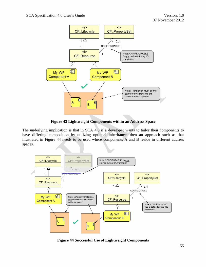
SCA Specification 4.0 User‘s Guide Version: 1.0
07 November 2012
55
Figure 43 Lightweight Components within an Address Space
The underlying implication is that in SCA 4.0 if a developer wants to tailor their components to
have differing composition by utilizing optional inheritance, then an approach such as that
illustrated in Figure 44 needs to be used where components A and B reside in different address
spaces.
Figure 44 Successful Use of Lightweight Components

SCA Specification 4.0 User‘s Guide Version: 1.0
07 November 2012
56
In practice this restriction should not be onerous because in most instances platform and application
components are delivered and deployed independently so no changes should be required to take
advantage of the potential savings provided by Lightweight Components. It is also the case that the
individual components of a single application will have the same configuration or any specialized
components will be targeted for a separate address space.
3.11.4 Implementation Considerations
One of the constraints levied on the use of Lightweight Components is that an
ApplicationManagerComponent is not able to use any of the lightweight configurations. This
constraint is included to preserve backwards compatibility with earlier implementations. Within the
CFApplication.idl the optional inheritance pre-compiler directives for CFResource.idl must be
defined at compile time because the inherited Resource interface is not optional.
Another important point to keep in consideration is that Lightweight Components are an optional
capability. If a developer chooses not to leverage any the optional inheritance capability then they
will be able to develop compliant applications that are very similar to those produced in accordance
with SCA 2.2.2. Some developers may determine that the changes influenced by Lightweight
Components do not exceed the cost benefit threshold tied to the change. However Lightweight
Components provide a common approach to optimize and tailor components for those that want to
use the capability.
3.12 SCA NEXT DEVELOPMENT RESPONSIBILITIES
3.12.1 Overview
SCA 4.0 contains a number of new component and interface definitions. An objective in the
evolution from SCA 2.2.2 was to provide additional clarification that would help document readers
become proficient with SCA more quickly by highlighting the areas for them to focus their
attention. SCA 4.0 section 2.2 provides insight by identifying which developers are involved in
realizing specific interfaces and components. Armed with that information a developer has the
ability to navigate through their higher priority sections of the specification.
3.12.2 Component Development Alignment
The SCA 4.0 documentation provides some separation between the components hosted by the radio
set versus those provided by waveforms. Figure 45 attempts to identify specific interfaces of
interest to the various stakeholders in a radio set architecture.

SCA Specification 4.0 User‘s Guide Version: 1.0
07 November 2012
57
Figure 45 General Allocation of Components to Radio Developers
SCA components are the elements that will be implemented by an SCA developer. Figure 45
identifies four classes of developers and a designation for an Abstract Component along its vertical
axis.
3.12.3 Component Products
The Abstract components encapsulate functionality that is not exposed directly to an external
consumer or provider. Abstract components can be realized independently and used by multiple
user facing components. ComponentBase is an example abstract component. It provides the core
abstraction, collection of interfaces, relationships and requirements that are used by other SCA
components. ComponentBase includes associations with the DomainProfile files and many of the
fundamental SCA interfaces such as the LifeCycle interface. Application Developers, Device
Developers, Service Developers and Core Platform Developers all create user facing components
that have an inheritance relationship with ComponentBase, i.e. each of those components are
responsible for providing interface realizations and fulfilling the applicable ComponentBase
requirements.
Application Developers provide user facing, software intensive solutions such as waveforms that
are deployed on the radio platform. In most cases a waveform will be delivered as a collection of
the Base Application Components. An application consists of assembly controller(s), application
resources and application component factories. The components are typically deployed separately
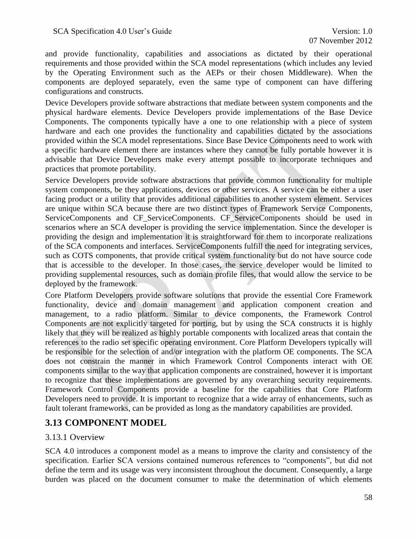
SCA Specification 4.0 User‘s Guide Version: 1.0
07 November 2012
58
and provide functionality, capabilities and associations as dictated by their operational
requirements and those provided within the SCA model representations (which includes any levied
by the Operating Environment such as the AEPs or their chosen Middleware). When the
components are deployed separately, even the same type of component can have differing
configurations and constructs.
Device Developers provide software abstractions that mediate between system components and the
physical hardware elements. Device Developers provide implementations of the Base Device
Components. The components typically have a one to one relationship with a piece of system
hardware and each one provides the functionality and capabilities dictated by the associations
provided within the SCA model representations. Since Base Device Components need to work with
a specific hardware element there are instances where they cannot be fully portable however it is
advisable that Device Developers make every attempt possible to incorporate techniques and
practices that promote portability.
Service Developers provide software abstractions that provide common functionality for multiple
system components, be they applications, devices or other services. A service can be either a user
facing product or a utility that provides additional capabilities to another system element. Services
are unique within SCA because there are two distinct types of Framework Service Components,
ServiceComponents and CF_ServiceComponents. CF_ServiceComponents should be used in
scenarios where an SCA developer is providing the service implementation. Since the developer is
providing the design and implementation it is straightforward for them to incorporate realizations
of the SCA components and interfaces. ServiceComponents fulfill the need for integrating services,
such as COTS components, that provide critical system functionality but do not have source code
that is accessible to the developer. In those cases, the service developer would be limited to
providing supplemental resources, such as domain profile files, that would allow the service to be
deployed by the framework.
Core Platform Developers provide software solutions that provide the essential Core Framework
functionality, device and domain management and application component creation and
management, to a radio platform. Similar to device components, the Framework Control
Components are not explicitly targeted for porting, but by using the SCA constructs it is highly
likely that they will be realized as highly portable components with localized areas that contain the
references to the radio set specific operating environment. Core Platform Developers typically will
be responsible for the selection of and/or integration with the platform OE components. The SCA
does not constrain the manner in which Framework Control Components interact with OE
components similar to the way that application components are constrained, however it is important
to recognize that these implementations are governed by any overarching security requirements.
Framework Control Components provide a baseline for the capabilities that Core Platform
Developers need to provide. It is important to recognize that a wide array of enhancements, such as
fault tolerant frameworks, can be provided as long as the mandatory capabilities are provided.
3.13 COMPONENT MODEL
3.13.1 Overview
SCA 4.0 introduces a component model as a means to improve the clarity and consistency of the
specification. Earlier SCA versions contained numerous references to ―components‖, but did not
define the term and its usage was very inconsistent throughout the document. Consequently, a large
burden was placed on the document consumer to make the determination of which elements

SCA Specification 4.0 User‘s Guide Version: 1.0
07 November 2012
59
described the necessary attributes of static versus the runtime system elements. The existence of the
components also provides a foundation for the proper use of software modeling and Model Driven
Development techniques within the development of SCA compliant products. Figure 46 contains
an illustration of some of the SCA components and their primary interfaces.
Figure 46 SCA Component Relationships
3.13.2 Interfaces and Components
SCA 2.2.2 was expressed in terms of interfaces, or more specifically CORBA interfaces.
Accompanying each interface specification was information describing its associations, semantics
and requirements. This allocation of information was often challenging for new readers of the
specification because it did not align with all of their expectations of what an interface should
provide and it did not support an easy decomposition of implementation responsibilities.
An interface is a shared boundary or connection between two entities. It specifies a well-defined,
and limited, role which needs to be fulfilled. The role may either be functional (defined specific
behavior to be performed; ―to do‖ or non-functional (identifies criteria used to judge the qualities
of operation: ―to be‖). Interfaces define ―what‖ needs to be done, ―why‖ something needs to be
done, but not ―how‖ to do it. As such, most pure interfaces tend to be stateless.
Since a well-defined interface needs to define a limited role, and complex system elements
generally need to fulfill multiple roles, multiple, separate interfaces are typically required to fully

SCA Specification 4.0 User‘s Guide Version: 1.0
07 November 2012
60
define the set of functional and non-functional requirements. It is often the case that multiple
interfaces need to interact with one another and only certain sequences of those interactions will
result in useful functionality. Therefore it is often useful to package these interactions between
multiple interfaces into an integrated unit of defined behavior known as a component.
A Component is an autonomous unit within a system or subsystem. Components provides one or
more interfaces which users may access and the internals of how they are provided are hidden and
inaccessible other than as provided by their interfaces.
Components encapsulate a modular, replaceable part of a system, which within its defined
environment:
implements a self-contained lifecycle, which may include sequential interaction
requirements which exist between multiple provided interfaces
presents a complete and consistent view of its execution requirements (MIPS, memory, etc)
to its physical environment
serves as a type definition, whose conformance is defined by its ‗provided‘ and ‗required‘
interfaces
encompasses static and dynamic semantics
Table 2 Characteristics of Component and Interfaces
Interface Characteristic Component Characteristic
Role -oriented best suited as problem domain
/ analysis-level abstractions
Service -oriented best suited as solution
domain / functional-level abstractions
Conceptual / Abstract / Unbounded
Responsibilities
Practical / Concrete / Constrained
Responsibilities
Have no implementation mechanisms Can – and often does – provide prototype or
default implementations
A necessary, though not sufficient, element of
Portability and Detailed Architecture / Design
Reuse
Properly-developed, Components improve
prospects of Portability and Detailed
Architecture / Design Reuse
Interfaces are generally SYNTAX without an
underlying SEMANTIC definition, and are
generally seen as STATELESS as a result
Components MUST HAVE well-defined
SEMANTIC baselines because they fulfill
multiple Roles within a Framework
Components are MUCH-MORE than the sum of
the Interfaces which they implement
3.13.3 Benefits and Implications
The introduction of the component model will provide a concrete bridge from interface to
implementation responsibilities and a well-defined path for integrating model based software
engineering techniques within the development process. Having these abilities will become even
more important and the use of new SCA optionality and extension mechanisms are more prevalent.
The textual and formatting changes associated with the incorporation of components within the
framework are visually intimidating because they introduce a large number of new sections, new
model elements and move text around. The division of responsibilities may at times look

SCA Specification 4.0 User‘s Guide Version: 1.0
07 November 2012
61
duplicative e.g. why there is a need for a DomainManager interface and a
DomainManagerComponent. However, as you read the corresponding sections you will see that in
most case the component oriented sections will include semantics and requirements associated with
a deployed and executing system or element.
In terms of the SCA product implementation, the impact of the component model should be
negligible. The component model does not contain any constructs that map into IDL, therefore any
requirements that are implemented by a product developer must be done within the context of the
IDL generated from the interface definitions. In fact, the layout represents how most current JTRS
SCA developments already implement their software elements:
the developer creates an implementation class that represents the component, e.g. an
ApplicationResourceComponent
the implementation class has associations with the classes that correspond to the
CF::Resource, PortAccessor, PropertySet and other interfaces
the implementation fulfills the roles and interfaces prescribed by its associated SCA
elements.
The component model is still a work in progress within the specification for a couple of reasons.
There were a number of modifications made to accommodate inclusion of the new concept and it is
fully expected that some elements that should have been moved were not. Secondly, at time of
publication, the group had not come to consensus on far reaching decisions such as whether or not
exception throwing should be described in an interface or component sections.
It is expected that these and other issues related to components will continue to evolve in future
revisions of the specification, however, consistent with the earlier discussions, these modifications
will improve the quality of the specifications and enhance its use within modeling environments
but they should have no impact on an SCA product implementation.

SCA Specification 4.0 User‘s Guide Version: 1.0
07 November 2012
62
3.14 SCA MAINTANENCE PROCESS – HOW TO DEVELOP A NEW PSM?
3.14.1 Overview
Figure 47 depicts how a proposed SCA change is handled. Proposed changes could be anything
from minor redlines to introducing a new capability within the specification. Successfully
implementing changes is a collaborative process that involves the change submitter, the ICWG
staff, the SCA working group and the JTNC. A summary of the process is that once an SCA
enhancement is submitted, the SCA working group will collaborated with the submitter to
determine if or how the enhancement should be integrated within the specification. Once the final
revisions are complete, the ICWG staff will work with the JTNC to develop a strategy regarding
when and how the change will be released. Detailed descriptions of the individual process actions
are beyond the scope of this document but may be obtained by contacting the ICWG staff at jtrs-
SCA Maintenance Process
Submitter
ICWG
Staff
SCA
Working
Group
JTNC
1
Prepare &
Submit
Proposal
Yes
3A
Prepare
& Submit
Briefing
No
4
Working
Group
Meeting
5B
Review
Proposal
5A
Adjudicate
Comments
3B
Approve?
7
Approve?
8B
Way
Forward?
9B
Release
Errata /
Corrigenda
Hold
8A
Revise &
Resubmit
Proposal
No
2
Redline?
End Process
9A
Release
Revision
Process
Legend
Process
ActionDecision
Sub
ProcessProcess Termination
6
Working
Group
Meeting
Yes
Issue
Revision
Issue
Errata /
Corrigenda
Figure 47 SCA Change Proposal Process
3.14.2 SCA Change Proposal Process – Submitter Roles
SCA has evolved largely based upon inputs, new ideas and lessons learned, from its community of
developers. Consequently, inputs from the submitter are an essential part of the process. The
primary role of the submitter is to collaborate with the SCA working group to communicate the
reason for or rationale associated with the change. The submitter will provide the information via a
change proposal form, discussions or documentation. The information can either be provided with
the submission or a byproduct of requests initiated by the working group.
SCA 4.0 provides a platform which will exercise this process as the specification was built with an
eye towards extensibility driven by the specification‘s user community. The SCA 4.0 design team
started with a full PSM definition that was equivalent to the definition of SCA 2.2.2, a vision for
how the specification should continue to evolve and an outline of an additional PSM. The initial
SCA working group was stretched thinly regarding the amount of staff that were available to define

SCA Specification 4.0 User‘s Guide Version: 1.0
07 November 2012
63
additional PSMs and did not want to expend a large amount of effort on a PSM that would not be
used. Therefore the group decided to proceed with a ―need based strategy‖ that would wait for a
community of interested users to drive the expansion of additional models.
The need based strategy would have a submitter develop an idea for a new PSM. The proposal, step
1 in Figure 47, could be anything from an errata to something that resembled an additional
document that was ready for inclusion to appendix E. The SCA working group would work with
the submitter to refine the proposal so that it would be ready for presentation to the larger ICWG
group in step 4. Beyond that point the idea would be fleshed out and refined until it reached a point
where it would be approved in step 7. Step 7 does represent a decision point where the change will
be voted upon, but practically speaking it is unlikely that a full version of a new PSM proposal will
reach this point if it doesn‘t have majority support of the SCA working group.
New PSM submissions should be presented in a format that is equivalent to that of the existing
appendices. Content wise the new proposal should cover equivalent ground of the current specs, i.e.
if an XML schema version of the descriptor files was to be proposed, it should support the
capabilities of the Document Type Definition (DTD) based descriptors. If it does not contain those
constructs then it would suggest that the DTDs be revisited to see if they could be removed from
there as well. If one were to introduce a new transport, then the design guidelines would encourage
the submitter to base their solution on standard technologies, exclude any capabilities that would be
detrimental to SDR solutions because of domain irrelevance, performance, sizing or security
considerations.
Once a new addition to the specification is approved, then the ICWG staff will collaborate with the
Joint Tactical Networking Center (JTNC) Technical Director (TD), per step 9, to release an update
to the specification. It is the objective that the introduction of new PSMs, if they are self-contained,
will not require a new SCA release however this numbering and organizational approach still needs
to be exercised.
3.15 UNITS OF FUNCTIONALITY AND SCA PROFILES
3.15.1 Overview
Earlier SCA versions have subscribed to a ―one size fits all‖ approach to implementation and
specification compliance. The documents contained descriptions of the SCA elements and
associated a set of requirements with each construct. When a developer chose to incorporate an
instance of one of those elements within their product they were responsible for implementing all
of the associated requirements or seeking a waiver for the capabilities that were not going to be
provided.
The SCA Units of Functionality (UOF) and Profiles were developed to address the restrictions
imposed by the earlier specifications. The intent of the UOFs is to introduce flexible constructs
within the framework so that it can accommodate platform (e.g. resource constrained, fixed wing
aircraft) and architecture (e.g. single versus multiple channel) specific requirements gracefully
which in turn will support the development of products destined for a specific target
implementation.
The primary benefit associated with having UOFs as part of the SCA is that they provide a
standardized approach that allows unnecessary interfaces and requirements to be omitted from a
component specification. The elimination of these requirements has the following ancillary
benefits:

SCA Specification 4.0 User‘s Guide Version: 1.0
07 November 2012
64
Reduced footprint – having the ability to omit unnecessary interfaces reduces the size of the
produced object. Even a stubbed interface realization requires a small amount of space and
these small savings can add up.
Increased assurance – reducing the size of the produced object also increases the degree to
which the code can be assessed. The reduction in size also minimizes the potential number
of locations in the product that could be exploited. Likewise, having dead or stubbed code
introduces additional locations where some could potentially go wrong or be injected.
Reduced development time – having fewer requirements to fulfill should have a direct
correlation with a smaller project and shorter development cycle.
Enhanced product performance – The smaller size and removal of the unnecessary modules
can improve the performance as there is less code to go through and there are fewer
motivations for superfluous context switches.
3.15.2 SCA UOFs and Profiles
SCA 4.0 UOFs were intended to be understood in a manner similar to their POSIX namesakes: a
Unit of Functionality is a subset of the larger specification that can be supported in isolation,
without a system having to support the whole specification. The initial design philosophy behind
UOFs was that they should be restricted to optional SCA features. However, this attitude broadened
as the specification matured so that there are some UOFs that are associated with mandatory
capabilities. Part of the rationale behind this expansion was to identify and highlight tightly
coupled requirements, the other reason was that there were discussions that some of those
capabilities might become optional in the future. Even with the expansion not all SCA
requirements are categorized with a UOF.
The Profiles comprise a set of UOFs, the collection of which is intended to be aligned with
common real world platform configurations. In SCA 4.0 Profiles are only applicable to OEs as it
was more convenient to forecast a relatively small set of common configurations for distinct classes
of target platforms. The concept is that an SCA radio can be an almost infinitely flexible platform
with the Full Profile, or very minimalist with the Lightweight Profile where the radio boots and
begins executing a single waveform with minimal configuration and processing.
3.15.3 Use of UOFs and Profiles
Appendix F (reference [6]), similar to many of the other SCA documents, provides a couple sample
conformance statements. The UOFs and Profiles provide the mechanism to align a product‘s design
with its mission. The product developer communicates a product‘s capabilities to external
consumers and stakeholders via its associated conformance statement:
―Product B is an SCA conformant Operating Environment (OE) in accordance with the
SCA Medium Profile containing an SCA Lightweight Application Environment Profile
conforming POSIX layer and an SCA Full CORBA Profile transfer mechanism‖.
In this example the statement contains an explicit reference to a profile (Medium). Figure 48 dictates
the approximately 259 requirements that are applicable requirements for this product. The Medium
profile contains the Management Registration, AEP Provider and Deployment UOFs and the specific
requirements are identified in the SCA Appendix F Attachment 1: SCA Conformance mapping
spreadsheet.

SCA Specification 4.0 User‘s Guide Version: 1.0
07 November 2012
65
Figure 48 SCA Profiles with OE Units of Functionality
The example conformance statement could be refined to also include additional units of
functionality as follows:
―Product B is an SCA conformant Operating Environment (OE) in accordance with the
SCA Medium Profile which contains an SCA Lightweight Application Environment Profile
conforming POSIX layer and an SCA Full CORBA Profile transfer mechanism, and
extended by the Log Capable, Log Producer and Event Channel UOFs‖
The majority of the SCAs ability to be tailored resides within the optional UOFs. At the
PlatformComponent level these units provide 8 standardized capabilities and approximately 226
requirements that could be applied to a component. The degree of encapsulation that was incorporated
within the design provides additional flexibility, such as the option of including a UOF during the
development phase and removing it prior to deployment.
The SCA was not developed with the intent of excluding a mandatory unit of functionality from a
profile. The likelihood of having to do so now is unlikely as the profiles do not include that many
UOFs, however the profile concept is still developing so the benefits of utilizing that type of
strategy will need to be evaluated if the need arises.

SCA Specification 4.0 User‘s Guide Version: 1.0
07 November 2012
66
3.16 WHAT ELEMENTS OF OMG IDL ARE ALLOWED IN THE PIM?
3.16.1 Overview
The SCA Platform Independent Model (PIM) is communicated two ways within the SCA. The PIM
is communicated via the UML models that are documented within the specification and accompany
the document. Per Section 3, the elements of the PIM are also communicated in IDL; ―OMG IDL is
the standard representation for the standalone interface definitions within the SCA platform
independent model‖.
The IDL representation of the ―SCA PIM‖ is a fixed entity that has its composition determined by
the entity that developed the specification. Consequently the question posed in this section is
irrelevant because there is no latitude for an SCA user to consider adding additional elements to the
formal ―SCA PIM‖.
3.16.2 PIM Background
The Object Management Group (OMG) defines a PIM as a representation that exhibits a degree of
platform independence so as to be suitable for use with a number of different platforms of similar
type. They suggest a common technique to employ in order to achieve platform independence is to
target a system model for a technology-neutral virtual machine.
3.16.3 PIM usage for SCA developers
Within a model driven architecture approach many transformations can occur within a single
abstraction layer. Therefore a user of the SCA PIM might choose to introduce several layers of
refinement of the SCA constructs as part of the system design and development process while
maintaining a platform independent model. The question of what IDL elements should be used is
very relevant for developers who are planning on refining their PIMs. If a waveform is intended to
be portable across multiple connection-mechanisms, then its IDL PIM should not introduce any
elements beyond those specified in Appendix E-3 (reference [8]).
3.16.4 Future PIM evolution
The projected evolution approach for the SCA PIM is that it will migrate to a model which relies
exclusively on UML. In that scenario the PIM would be fully integrated within a tool-based,
largely automated software development process. System developers within this approach would
execute all of their PIM refinement in the tool and in UML. When the modeler was ready to
transition to a platform specific representation, this approach would treat IDL as a platform specific
realization and the tool would facilitate the mapping to the target technology. Unfortunately we are
not yet at a point where we can utilize this approach because the state of the art tools do not
sufficiently support an automated generation of our desired mappings.
Nonetheless, in this scenario, the PIM would still be governed by the constructs defined in
Appendix E-3 (reference [8]); however the restrictions would be less apparent to the system
architect.
3.17 WHAT IS THE IMPACT OF THE SCA 4.0 PORT CHANGES?
3.17.1 Overview
One of the SCA 4.0 changes that has drawn considerable interest has been the refactoring of the
port related interfaces. The specification introduced a new interface, PortAccessor, which
consolidated the Port and PortSupplier interfaces. The new interface represents a change in the
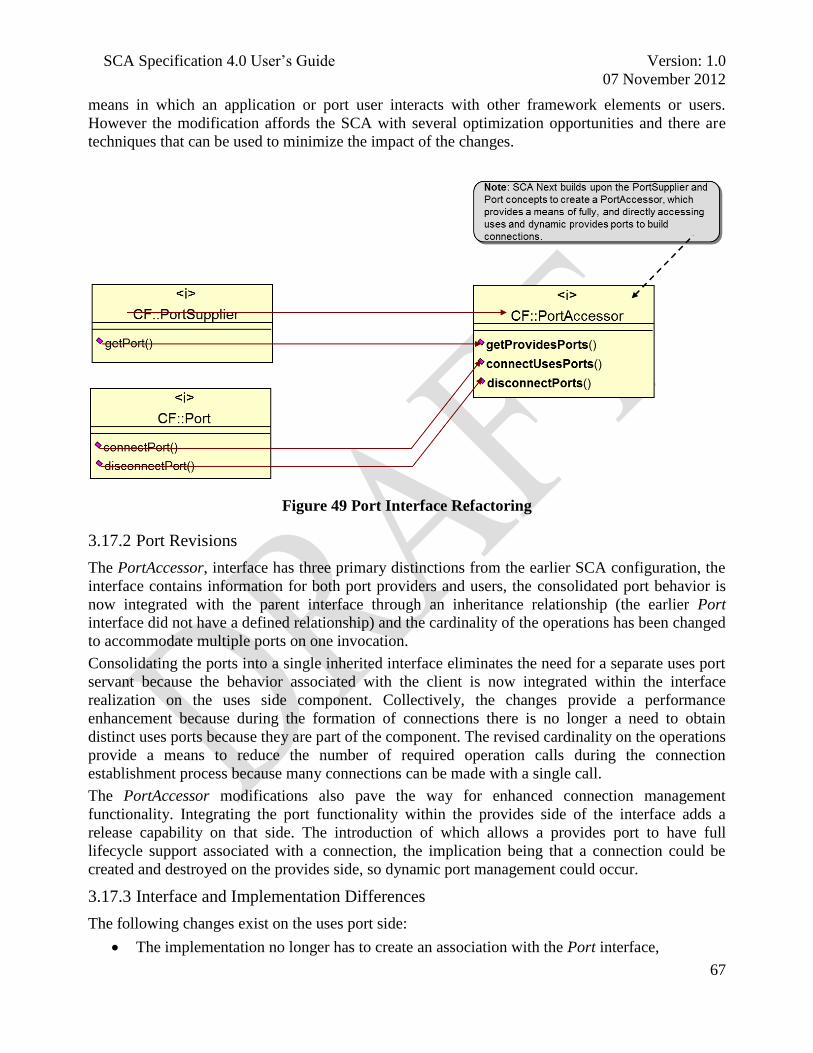
SCA Specification 4.0 User‘s Guide Version: 1.0
07 November 2012
67
means in which an application or port user interacts with other framework elements or users.
However the modification affords the SCA with several optimization opportunities and there are
techniques that can be used to minimize the impact of the changes.
Figure 49 Port Interface Refactoring
3.17.2 Port Revisions
The PortAccessor, interface has three primary distinctions from the earlier SCA configuration, the
interface contains information for both port providers and users, the consolidated port behavior is
now integrated with the parent interface through an inheritance relationship (the earlier Port
interface did not have a defined relationship) and the cardinality of the operations has been changed
to accommodate multiple ports on one invocation.
Consolidating the ports into a single inherited interface eliminates the need for a separate uses port
servant because the behavior associated with the client is now integrated within the interface
realization on the uses side component. Collectively, the changes provide a performance
enhancement because during the formation of connections there is no longer a need to obtain
distinct uses ports because they are part of the component. The revised cardinality on the operations
provide a means to reduce the number of required operation calls during the connection
establishment process because many connections can be made with a single call.
The PortAccessor modifications also pave the way for enhanced connection management
functionality. Integrating the port functionality within the provides side of the interface adds a
release capability on that side. The introduction of which allows a provides port to have full
lifecycle support associated with a connection, the implication being that a connection could be
created and destroyed on the provides side, so dynamic port management could occur.
3.17.3 Interface and Implementation Differences
The following changes exist on the uses port side:
The implementation no longer has to create an association with the Port interface,
SCA Specification 4.0 User‘s Guide Version: 1.0
07 November 2012
68
The client will need to change any of its Port references to PortAccessor,
The realized operation names will change from connectPort and disconnectPort to
connectUsesPorts and disconnectPorts.
The logic change associated with the operation change should be straightforward as at will only
need to be amended to accept lists of connection endpoints rather than a single endpoint.
A comparable set of changes will need to be performed on the provides ports:
The interface definitions will change, which in turn will force an IDL recompilation
The realized operation name will change from getPorts to getProvidesPorts
Associated with these changes, the new operation will return a void rather than an object reference
and the parameter will no longer be a name, but a connection structure.
3.17.4 Implementation Implications
There are steps that can be employed to minimize the impact of the port related changes on an
implementation. Figure 50 highlights some of the similarities and differences of the SCA 4.0 and
SCA 2.2.2 port and connection implementations.
Figure 50 Port Implementation Differences
An SCA implementation could choose to create a ―new‖ realization of the PortAccessor interface.
This would be a reasonable approach to take, especially in instances where there are a limited
number of locations where the code would need to be redone. This approach would likely be
palatable in these situations because, in an unenhanced implementation the PortAccessor
operations should not have very complex application logic.
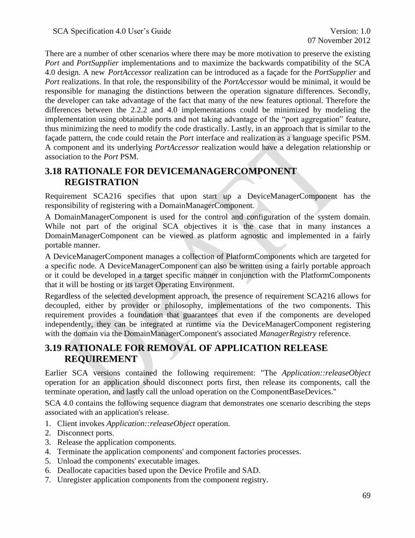
SCA Specification 4.0 User‘s Guide Version: 1.0
07 November 2012
69
There are a number of other scenarios where there may be more motivation to preserve the existing
Port and PortSupplier implementations and to maximize the backwards compatibility of the SCA
4.0 design. A new PortAccessor realization can be introduced as a façade for the PortSupplier and
Port realizations. In that role, the responsibility of the PortAccessor would be minimal, it would be
responsible for managing the distinctions between the operation signature differences. Secondly,
the developer can take advantage of the fact that many of the new features optional. Therefore the
differences between the 2.2.2 and 4.0 implementations could be minimized by modeling the
implementation using obtainable ports and not taking advantage of the ―port aggregation‖ feature,
thus minimizing the need to modify the code drastically. Lastly, in an approach that is similar to the
façade pattern, the code could retain the Port interface and realization as a language specific PSM.
A component and its underlying PortAccessor realization would have a delegation relationship or
association to the Port PSM.
3.18 RATIONALE FOR DEVICEMANAGERCOMPONENT
REGISTRATION
Requirement SCA216 specifies that upon start up a DeviceManagerComponent has the
responsibility of registering with a DomainManagerComponent.
A DomainManagerComponent is used for the control and configuration of the system domain.
While not part of the original SCA objectives it is the case that in many instances a
DomainManagerComponent can be viewed as platform agnostic and implemented in a fairly
portable manner.
A DeviceManagerComponent manages a collection of PlatformComponents which are targeted for
a specific node. A DeviceManagerComponent can also be written using a fairly portable approach
or it could be developed in a target specific manner in conjunction with the PlatformComponents
that it will be hosting or its target Operating Environment.
Regardless of the selected development approach, the presence of requirement SCA216 allows for
decoupled, either by provider or philosophy, implementations of the two components. This
requirement provides a foundation that guarantees that even if the components are developed
independently, they can be integrated at runtime via the DeviceManagerComponent registering
with the domain via the DomainManagerComponent's associated ManagerRegistry reference.
3.19 RATIONALE FOR REMOVAL OF APPLICATION RELEASE
REQUIREMENT
Earlier SCA versions contained the following requirement: "The Application::releaseObject
operation for an application should disconnect ports first, then release its components, call the
terminate operation, and lastly call the unload operation on the ComponentBaseDevices."
SCA 4.0 contains the following sequence diagram that demonstrates one scenario describing the steps
associated with an application's release.
1. Client invokes Application::releaseObject operation.
2. Disconnect ports.
3. Release the application components.
4. Terminate the application components' and component factories processes.
5. Unload the components' executable images.
6. Deallocate capacities based upon the Device Profile and SAD.
7. Unregister application components from the component registry.

SCA Specification 4.0 User‘s Guide Version: 1.0
07 November 2012
70
8. Generate an event to indicate the application has been removed from the domain.
Figure 51 Sequence Diagram depicting application release behavior
The consensus was that this requirement was no longer necessary within SCA 4.0 because the well-
defined ordering that was specified within the requirement did not need to be preserved because the
Application interface contains individual requirements for the disconnect, terminate, release and
unload behavior and the relative ordering of those calls is dictated by their semantics.
3.20 HOW TO FIND AND USE DOMAIN REGISTRY REFERENCES
3.20.1 Overview
A DomainManagerComponent needs to maintain awareness of two registry instances in order to
function properly within an installation, one for component and the other for manager registration.
The two instances account for the different styles of PlatformComponent registration that can occur
within a radio set.
sd Application Behav ior
CF::CommUser
«interface»
:FullComponentRegistry
«interface»
:ExecutableDevice
«interface»
:PortAccessor
«interface»
:Application
:EventComponent«interface»
:LifeCycle
releaseObject()
disconnectPorts(Disconnections)
releaseObject()
terminate(ProcessID_Type)
unload(string)
deallocateCapacity(Properties)
unregisterComponent(string)
generate event
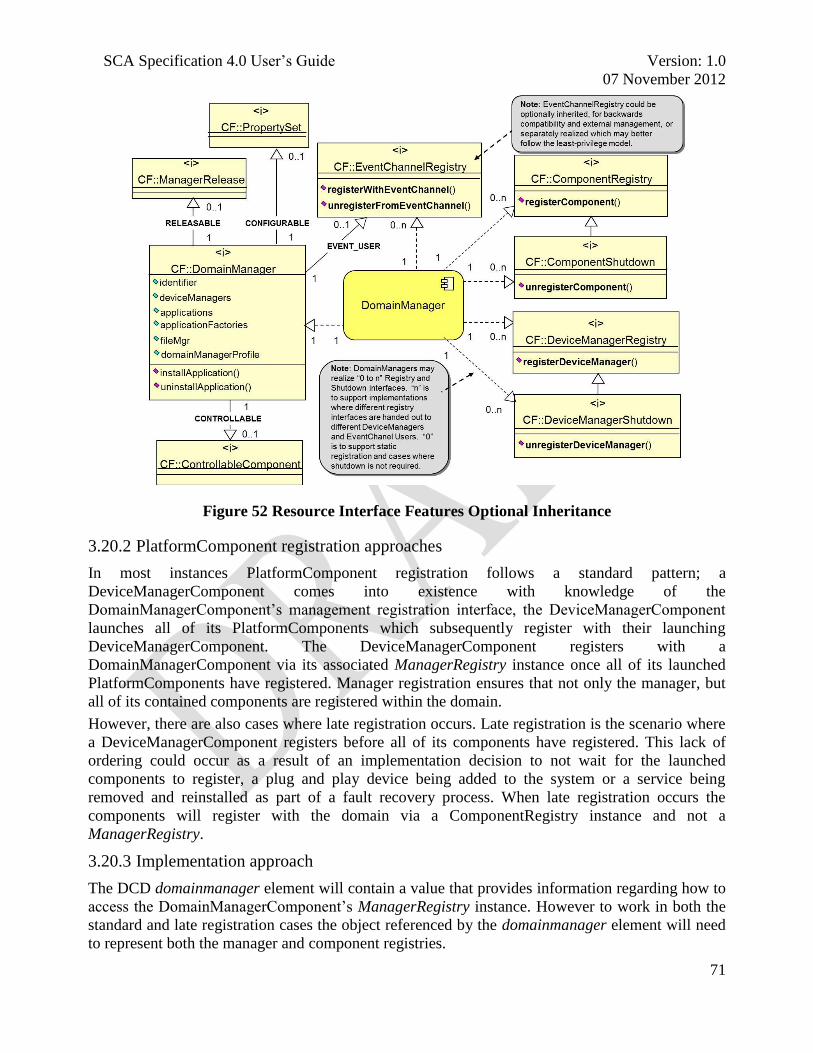
SCA Specification 4.0 User‘s Guide Version: 1.0
07 November 2012
71
Figure 52 Resource Interface Features Optional Inheritance
3.20.2 PlatformComponent registration approaches
In most instances PlatformComponent registration follows a standard pattern; a
DeviceManagerComponent comes into existence with knowledge of the
DomainManagerComponent‘s management registration interface, the DeviceManagerComponent
launches all of its PlatformComponents which subsequently register with their launching
DeviceManagerComponent. The DeviceManagerComponent registers with a
DomainManagerComponent via its associated ManagerRegistry instance once all of its launched
PlatformComponents have registered. Manager registration ensures that not only the manager, but
all of its contained components are registered within the domain.
However, there are also cases where late registration occurs. Late registration is the scenario where
a DeviceManagerComponent registers before all of its components have registered. This lack of
ordering could occur as a result of an implementation decision to not wait for the launched
components to register, a plug and play device being added to the system or a service being
removed and reinstalled as part of a fault recovery process. When late registration occurs the
components will register with the domain via a ComponentRegistry instance and not a
ManagerRegistry.
3.20.3 Implementation approach
The DCD domainmanager element will contain a value that provides information regarding how to
access the DomainManagerComponent‘s ManagerRegistry instance. However to work in both the
standard and late registration cases the object referenced by the domainmanager element will need
to represent both the manager and component registries.

SCA Specification 4.0 User‘s Guide Version: 1.0
07 November 2012
72
Figure 53 Resource Interface Features Optional Inheritance
An approach that could be used to address this problem would be for the Core Framework Control
Developer to create a new interface that inherited from both the ComponentRegistry and
ManagerRegistry interfaces. An instance of the developer provided interface could then be used to
accept requests via either interface and integrate information regarding all of the registered
components within a single ManagerType struct that is associated with a specific
DeviceManagerComponent.
3.21 LEGACY SUPPORT VIA V222_COMPAT DIRECTIVE
In addition to the optional inheritance pre-compiler directives discussed in section 3.9, SCA 4.0
provides an additional pre-compiler directive that establishes a base for legacy support. This pre-
compiler directive, V222_COMPAT permits developers to enable all the optional inheritances as it
was with previous versions of the SCA. To use the V222_COMPAT one must define this directive
at IDL file compile time. As mentioned previously, this is only a partial solution for full legacy
backward compatibility since SCA 4.0 has reworked the port interfaces.
In addition to the directives and optional inheritance there are other minor interface changes that
distinguish an SCA 4.0 from a 2.2.2 one but COTS development tools should be able easily
accommodate for those differences.
3.22 COMPONENT LIFE CYCLE
3.22.1 Overview
SCA provides support for some Core Framework Control components, notably what occurs when a
DeviceManagerComponent transitions into an out of existence, but there is a lack of concrete
guidance regarding the lifecycle for ComponentBase based components. The life cycles associated
with these components range from characterizing the state transitions that exist for an
ApplicationResourceComponent as a waveform is installed or managed to describing the specifics
of what is required to bring a radio platform into existence.
3.22.2 ComponentBase State Model <Requesting Additional Input>
This instance of the ComponentBase state model semantics (legitimate operations and transitions)
depend on the presence of the LifeCycle interface and support of the CONTROLLABLE flag.

SCA Specification 4.0 User‘s Guide Version: 1.0
07 November 2012
73
Figure 54 Component Life Cycle
[Note: Soliciting community for additional content to be added here. Please submit input to jtrs-
3.23 CONFIGURATION PROPERTIES <REQUESTING ADDITIONAL
INPUT>
[Note: Soliciting community for additional content to be added here. Please submit input to jtrs-
3.24 BYPASS
3.24.1 Overview
SCA 4.0 does not explicitly address security concerns although many developers will use SCA to
build security aware devices. Ideally architectural decisions should be made which will minimize
SCA Specification 4.0 User‘s Guide Version: 1.0
07 November 2012
74
or eliminate the need for bypassing security controls or devices. However, that approach may not
be practical or realizable.
The SCA design team felt that the concept of bypass was important enough that although it was
beyond the scope of the specification that it warranted a collection of common definitions so that it
could be discussed and utilized consistently across SCA implementations. The definitions do not
presuppose whether or not bypass is positive, negative, necessary or unnecessary, they simply
establish a common vocabulary for the topic.
3.24.2 Definitions
Security Domain – A set of objects sharing common Information Assurance properties such as
security classification level or integrity.
Bypass – An information flow even that transports information without introducing an additional
level of encryption or decryption from one security domain to a security domain with incompatible
security properties.
Bypass Policy – Establishes the rules that govern the format and pace of data that is allowed to
cross between security domains unaltered.
Bypass Guard – A system entity that enforces a bypass policy.
In Band Bypass – Bypass which conforms with a corresponding bypass policy of a portion
(typically unencrypted) of an actual data payload (i.e. waveform user traffic)
Out of Band Bypass – Bypass which conforms with a corresponding bypass policy of a completely
unencrypted non-waveform user traffic data payload (see Figure 55).

SCA Specification 4.0 User‘s Guide Version: 1.0
07 November 2012
75
Figure 55 Illustration of Bypass Concepts
Out of
Band
Bypass
Guard
Crypto
Device
Policy
Store Security
Domain 2
Security
Domain 1
In Band
Bypass
Guard
In Band Data Waveform
Header
Out of Band
Data
Control
Status
Data
Waveform
Data
Waveform
Header and
Encrypted Data

SCA Specification 4.0 User‘s Guide Version: 1.0
07 November 2012
76
4 ACRONYMS
Abbreviation Definition
AEP Application Environment Profile
API Application Program Interface
CF Core Framework
CORBA Common Object Request Broker Architecture
CORBA/e Embedded Real Time CORBA
COTS Commercial Off The Shelf
CPFSK Continuous Phase Frequency Shift Keying
CVSD Continuously Variable-Slope Delta modulation
DCD Device Configuration Descriptor
DLC Data Link Control
DSP Digital Signal Processor
DTD Document Type Definition
FM3TR Future Multiband Multiwaveform Modular Tactical Radio
FPGA Field Programmable Gate Array
GPP General Purpose Processor
GPS Global Positioning System
ICWG Interface Control Working Group
ID Identifier
IDL Interface Definition Language
IEEE Institute of Electrical and Electronic Engineers
JPA JTRS Platform Adapter
JTNC Joint Tactical Networking Center
JTR Joint Tactical Radio
JTRS Joint Tactical Radio System
LwAEP Lightweight Application Environment Profile
MAC Media Access Control
MILCOM Military Communications Conference
MIPS Million Instructions Per Second
MHAL Modem Hardware Abstraction Layer

SCA Specification 4.0 User‘s Guide Version: 1.0
07 November 2012
77
Abbreviation Definition
MOCB MHAL On Chip Bus
OE Operating Environment
OMG Object Management Group
ORB Object Request Broker
PIM Platform Independent Model
POSIX
Portable Operating System Interface
PSM Platform Specific Model
RPC Remote Procedure Control
R-S Reed Solomon
SAD Software Assembly Descriptor
SCA Software Communications Architecture
SCD Software Component Descriptor
SDR Software Defined Radio
SPD Software Profile Descriptor
TCP-IP Transmission Control Protocol (TCP) and Internet Protocol (IP)
TD Technical Director
TDMA Time Division Multiplexed Access
UI User Interface
UML Unified Modeling Language
UOF Unit of Functionality
WF Waveform
XML eXtensible Markup Language
POSIX is a registered trademark of the Institute of Electrical and Electronics Engineers, Inc.