New ‘LOW PIM’ - Mouser Electronics Low PIM Switches... · •Low PIM product information •Low...
22
New ‘LOW PIM’ COAXIAL SWITCHES February 2014
Transcript of New ‘LOW PIM’ - Mouser Electronics Low PIM Switches... · •Low PIM product information •Low...
New ‘LOW PIM’
COAXIAL SWITCHES
February 2014
Confidential 2/21/2014 2
This document and all information contained herein
is the sole property of Radiall and is subject to the
confidentiality obligations of the recipient.
This document shall not be reproduced or disclosed
to any third party for any purpose whatsoever or used
for manufacturing purposes without prior written
agreement from Radiall.
No intellectual property rights are granted by the
delivery of this document or the disclosure of its content.
The statements made herein do not constitute an offer.
Confidential 2/21/2014 2
Table of Contents
• Introduction
• Low PIM range
• Low PIM product information
• Low PIM applications
• Product benefits
2/21/2014 Confidential 3
Introduction
2/21/2014 Confidential 4
Introduction: What is PIM ?
• Passive Intermodulation (PIM) is a signal distortion that occurs when
signals at several frequencies are transmitted through a passive device
(connector, cable, switch, antennas…) which has some non-linear
response. In return the fundamental frequencies will be distorted and
series of higher order harmonic frequencies will appear in the frequency
domain. If some of these frequencies appear in the receiving band of a
wireless system it will raise the receiver floor noise and reduce the
system performance.
• The main sources of intermodulation in wireless systems are the active
devices in transceivers and receivers. Their intermodulation can be
reduced or eliminated by filtering which is not possible for passive devices
inserted in transmission line. Therefore when intermodulation becomes
critical for a system the only solution is to use Low PIM passive devices.
2/21/2014 Confidential 5
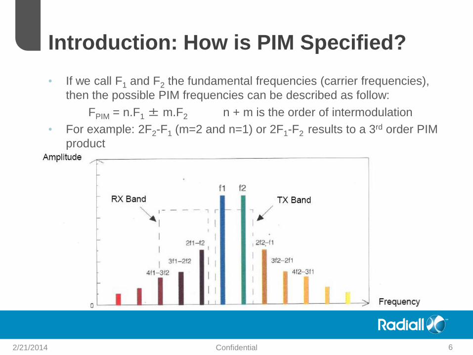
• If we call F1 and F2 the fundamental frequencies (carrier frequencies),
then the possible PIM frequencies can be described as follow:
FPIM = n.F1 ± m.F2 n + m is the order of intermodulation
• For example: 2F2-F1 (m=2 and n=1) or 2F1-F2 results to a 3rd order PIM
product
Introduction: How is PIM Specified?
2/21/2014 Confidential 6
Introduction: How is PIM Specified?
• Usually odd PIM orders (3rd, 5th, 7th orders) are the main concern
because their frequencies are close from the carrier frequency and
may disturb the system behavior. As the strength of the signal
decreases with the order of PIM, the 3rd order is often the most
critical and is the one usually tested and specified by component
manufacturers.
• PIM is specified in dBc and dBm terms
• dBm is a measure of power relative to 1mW
• dBc is a measure of dB below a given carrier level. A typical power level in
testing passive devices is +43dBm (20W). In that case if the PIM level is -
110dBm, it is equivalent to a PIM level value of: -110-43= -153dBc
A low PIM device has typically a PIM level of -150 to -160 dBc
2/21/2014 Confidential 7
Introduction: Telecom Situation
• Today there is a growing demand on wireless communication
devices with higher data rates. 4G or LTE (Long Term Evolution) is
the fourth generation standard for mobile phone and allows
supplying speeds almost 10 times higher than current networks
and providing an answer to this frenetic growth of data
consumption. The deployment of 4G networks is designed to cope
with the explosion of mobile use. Data volumes on the network
operator at Orange status, and have been multiplied by 68 in 5
years and will continue to grow by a factor of 7 by 2015
• This exploding demand will request wireless and RF systems to
be very reliable and to work with their full coverage capacity. Since
PIM could seriously impact their performances, the low PIM
devices will be of high interest for wireless and RF Test industry.
2/21/2014 Confidential 8
Low PIM Range
2/21/2014 Confidential 9
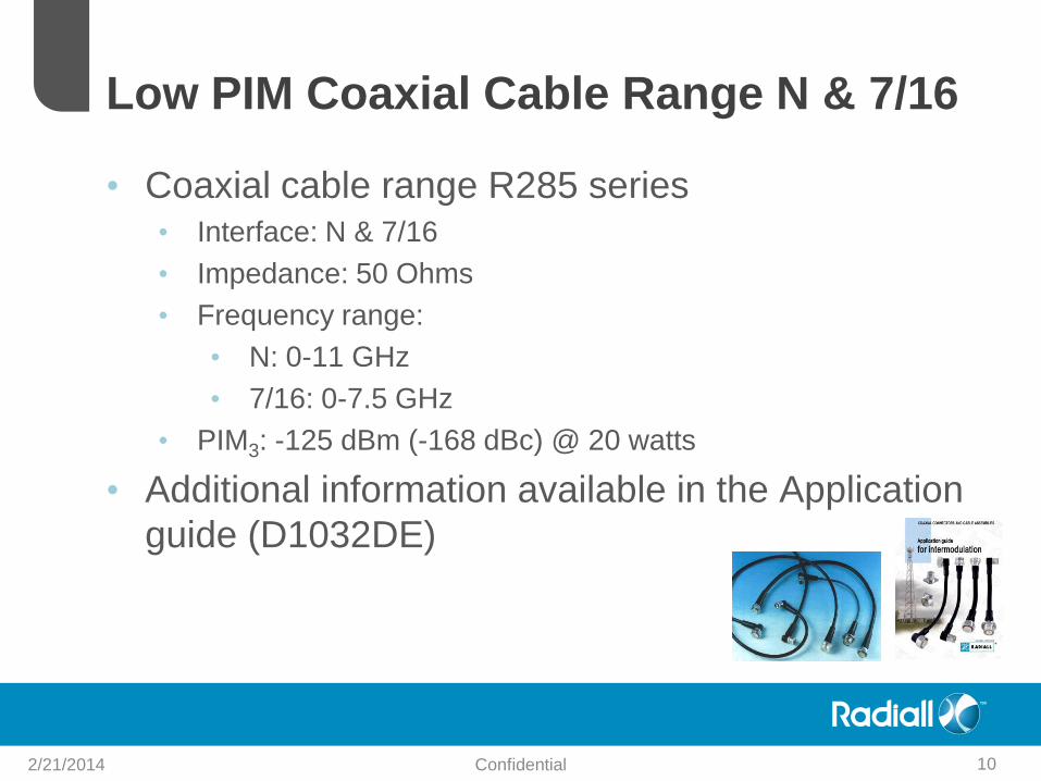
Low PIM Coaxial Cable Range N & 7/16
• Coaxial cable range R285 series • Interface: N & 7/16
• Impedance: 50 Ohms
• Frequency range:
• N: 0-11 GHz
• 7/16: 0-7.5 GHz
• PIM3: -125 dBm (-168 dBc) @ 20 watts
• Additional information available in the Application
guide (D1032DE)
2/21/2014 Confidential 10
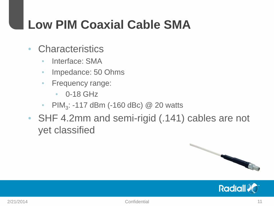
Low PIM Coaxial Cable SMA
• Characteristics • Interface: SMA
• Impedance: 50 Ohms
• Frequency range:
• 0-18 GHz
• PIM3: -117 dBm (-160 dBc) @ 20 watts
• SHF 4.2mm and semi-rigid (.141) cables are not
yet classified
2/21/2014 Confidential 11
Confidential 2/21/2014 12
Product Information
Product information
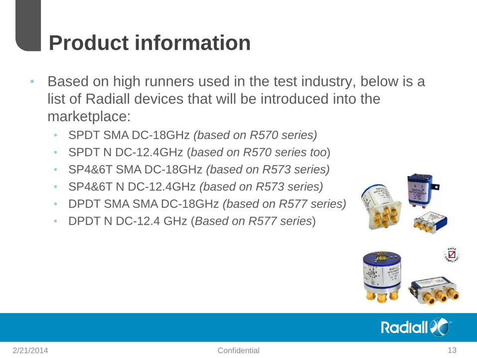
• Based on high runners used in the test industry, below is a
list of Radiall devices that will be introduced into the
marketplace:
• SPDT SMA DC-18GHz (based on R570 series)
• SPDT N DC-12.4GHz (based on R570 series too)
• SP4&6T SMA DC-18GHz (based on R573 series)
• SP4&6T N DC-12.4GHz (based on R573 series)
• DPDT SMA SMA DC-18GHz (based on R577 series)
• DPDT N DC-12.4 GHz (Based on R577 series)
2/21/2014 Confidential 13
Product Information
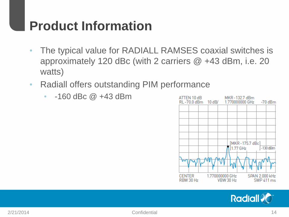
• The typical value for RADIALL RAMSES coaxial switches is
approximately 120 dBc (with 2 carriers @ +43 dBm, i.e. 20
watts)
• Radiall offers outstanding PIM performance
• -160 dBc @ +43 dBm
2/21/2014 Confidential 14

• Part number selection: (132 part numbers)
• SPDT SMA DC -18 GHz
• SPDT N D -12.4 GHz
Product Information
2/21/2014 Confidential 15
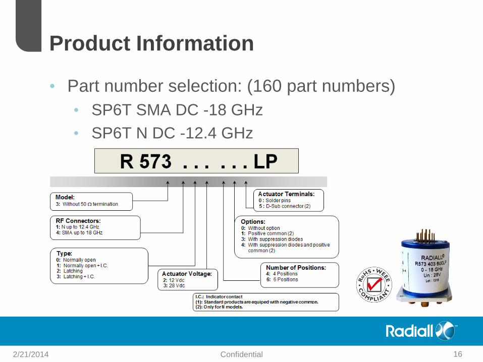
• Part number selection: (160 part numbers)
• SP6T SMA DC -18 GHz
• SP6T N DC -12.4 GHz
Product Information
2/21/2014 Confidential 16
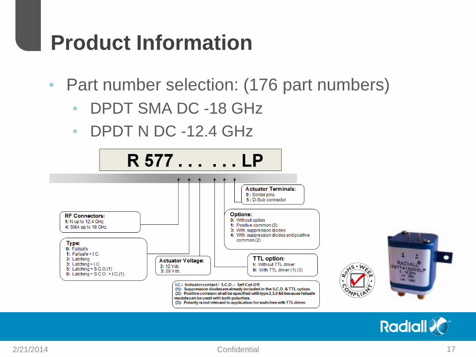
• Part number selection: (176 part numbers)
• DPDT SMA DC -18 GHz
• DPDT N DC -12.4 GHz
Product Information
2/21/2014 Confidential 17
Applications
2/21/2014 Confidential 18
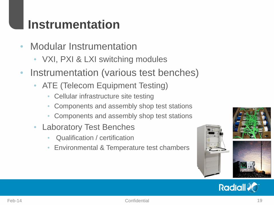
Instrumentation
Feb-14 19 Confidential
• Modular Instrumentation
• VXI, PXI & LXI switching modules
• Instrumentation (various test benches)
• ATE (Telecom Equipment Testing)
• Cellular infrastructure site testing
• Components and assembly shop test stations
• Components and assembly shop test stations
• Laboratory Test Benches
• Qualification / certification
• Environmental & Temperature test chambers

Product Benefits
Feb-14 20 Confidential

• Life span: 2 million cycles
• Performance: -160 dBc (PIM 3rd order frequency)
• Only Dow-key products offer the same Low PIM level
• Other competitors: -150 dBc max
• Additional Low PIM Radiall devices (various
coaxial cables)
• Large offer (500 part numbers) because it’s a
RAMSES extension range
• Competitive price
Product Benefits
2/21/2014 Confidential 21

• Please let us know how we
can support your needs
• Switch Support For Questions Email:
USA: [email protected]
Worldwide: [email protected]
• Thank you!
2/21/2014 Confidential 22