CAUSE AND EFFECT By Helena Sánchez & Claudia Rodríguez Claudia Rodríguez.

1
Smith, Claudia
From: Smith, Claudia
Sent: Tuesday, September 05, 2017 10:56 AM
Subject: Notice of Issuance of Permit to Construct on the Uintah and Ouray Indian Reservation
This is to notify you that the EPA has issued a final Clean Air Act (CAA) synthetic minor permit to construct
for the existing Anadarko Uintah Midstream, LLC, Antelope Flats and Sand Wash Compressor Stations with
South Central Tank Battery pursuant to the Tribal Minor New Source Review (MNSR) Permit Program at 40
CFR Part 49. The final MNSR permit, response to comments and administrative permit record will be available
in PDF format on our website at: http://www.epa.gov/caa-permitting/caa-permits-issued-epa-region-8.
In accordance with the regulations at §49.159(a), the permit will be effective 30 days after the date of this
notice, on October 5, 2017. Within 30 days after a final permit decision has been issued, any person who filed
comments on the proposed permit or participated in the public hearing may petition the Environmental Appeals
Board (EAB) to review any condition of the permit decision. The 30-day period within which a person may
request review under this section begins when we have fulfilled the notice requirements for the final permit
decision. Motions to reconsider a final order by the EAB must be filed within 10 days after service of the final
order. A petition to the EAB is under Section 307(b) of the CAA, a prerequisite to seeking judicial review of
the final agency action. For purposes of judicial review, final agency action occurs when we issue or deny a
final permit and agency review procedures are exhausted.
Thank you,
Claudia Young Smith
Environmental Scientist
Air Program
U.S. Environmental Protection Agency, Region 8
Tel: (303) 312-6520
Email: [email protected]
Web: http://www.epa.gov/caa-permitting/caa-permitting-epas-mountains-and-plains-region
Mail: 1595 Wynkoop Street, Mail Code 8P-AR, Denver, Colorado 80202
*******************************************************************

1
Smith, Claudia
From: Smith, Claudia
Sent: Tuesday, September 05, 2017 10:47 AM
Cc: Ohlhausen, Natalie ([email protected]); Minnie Grant; Bruce Pargeets;
Fallon, Gail
Subject: Final SMNSR Permit for Antelope Flats and Sand Wash Compressor Stations with South
Central Tank Battery
Attachments: Anadarko Antelope Flats-Sand Wash RTC & Final Permit SMNSR-UO-000027-2012
001.pdf
Mr. Rhoton,
I have attached the final requested permit and the accompanying response to comments document for the
Antelope Flats and Sand Wash Compressor Stations with South Central Tank Battery, issued pursuant to the
Tribal Minor New Source Review (MNSR) Program at 40 CFR Part 49. We will also be posting the final
MNSR permit and response to comments and the administrative permit record in PDF format on our website at:
http://www.epa.gov/caa-permitting/caa-permits-issued-epa-region-8.
In accordance with the regulations at §49.159(a), the permit will be effective 30 days after the date of this
notice, on October 5, 2017. Within 30 days after a final permit decision has been issued, any person who filed
comments on the proposed permit or participated in the public hearing may petition the Environmental Appeals
Board (EAB) to review any condition of the permit decision. The 30-day period within which a person may
request review under this section begins when we have fulfilled the notice requirements for the final permit
decision. Motions to reconsider a final order by the EAB must be filed within 10 days after service of the final
order. A petition to the EAB is under Section 307(b) of the CAA, a prerequisite to seeking judicial review of the
final agency action. For purposes of judicial review, final agency action occurs when we issue or deny a final
permit and agency review procedures are exhausted.
If you have any questions or concerns regarding this final permit action, or would like a paper copy, please
contact me.
Thank you,
Claudia Young Smith Environmental Scientist
Air Program
U.S. Environmental Protection Agency, Region 8
Tel: (303) 312-6520
Email: [email protected]
Web: http://www.epa.gov/caa-permitting/caa-permitting-epas-mountains-and-plains-region
Mail: 1595 Wynkoop Street, Mail Code 8P-AR, Denver, Colorado 80202
*******************************************************************


1
Smith, Claudia
From: Smith, Claudia
Sent: Friday, June 09, 2017 1:45 PM
Subject: Notice of Public Comment Period – Proposed Permit to Construct on the Uintah and
Ouray Indian Reservation
Attachments: Anadarko Antelope Flats-Sand Wash-SCTB Bulletin Board Notice.pdf
In accordance with the regulations at 40 CFR 49.157 and 49.158, the EPA is hereby providing notification of
the availability for public comment of the proposed Clean Air Act synthetic minor New Source Review permit
for the following source located on the Uintah and Ouray Indian Reservation:
Anadarko Uintah Midstream, LLC – Antelope Flats & Sand Wash Compressor Stations with South Central
Tank Battery
Electronic copies of the proposed permit, technical support document, application and other supporting permit
information may be viewed online at http://www.epa.gov/caa-permitting/caa-permit-public-comment-
opportunities-region-8.
Paper copies of the proposed permit, technical support document, application, and other supporting permit
information may be reviewed by contacting the Federal and/or Tribal contacts identified on the attached public
notice bulletin.
Comments may be sent by mail to:
US EPA Region 8
Air Program Office
1595 Wynkoop Street, 8P-AR
Denver, CO 80202
Attn: Tribal NSR Coordinator
or
Electronically to [email protected]
In accordance with the regulations at §49.157, the Agency is providing a 30-day period from June 12, 2017
through July 13, 2017, for public comment on this proposed permit. Comments must be received by 5:00pm
MT July 13, 2017, to be considered in the issuance of the final permit. If a public hearing is held regarding this
permit, you will be sent a copy of the public hearing notice at least 30 days in advance of the hearing date.
Claudia Young Smith
Environmental Scientist
Air Program, Mail Code 8P-AR
US Environmental Protection Agency Region 8
1595 Wynkoop Street
Denver, Colorado 80202
Phone: (303) 312-6520
Fax: (303) 312-6064
http://www.epa.gov/caa-permitting/caa-permitting-epas-mountains-and-plains-region

2
*******************************************************************

1
Smith, Claudia
From: Smith, Claudia
Sent: Tuesday, June 06, 2017 4:51 PM
Cc: Bruce; [email protected]; Fallon, Gail; Morales, Monica;
[email protected]; Schwartz, Colin
Subject: CORRECTION: Proposed Synthetic Minor NSR Permit for Antelope Flats and Sand Wash
Compressor Stations with SCTB
Attachments: Anadarko Antelope Flats-Sand Wash-SCTB Bulletin Board Notice.pdf; Anadarko
Antelope Flats-Sand Wash-SCTB Proposed SMNSR Permit-TSD.pdf
(Please note corrected public comment period dates and corrected PDF attachments – Disregard email sent by
Colin Schwartz on May 31, 2017)
Mr. Rhoton,
I have attached the requested proposed permit, the accompanying technical support document, and the bulletin
board notice for the Antelope Flats and Sand Wash Compressor Stations with SCTB. We will also be posting
the application, proposed permit, technical support document, and other supporting information in PDF format
on our website at http://www2.epa.gov/caa-permitting/caa-permit-public-comment-opportunities-region-8 by the
start of the public comment period.
In accordance with the regulations at 40 CFR 49.157, we are providing a 30-day period from June 12, 2017 to
July 13, 2017 for public comment on this proposed permit. Comments must be received by 5:00pm MDT July
13, 2017, to be considered in the issuance of the final permit.
Please submit any written comments you may have concerning the terms and conditions of this permit. You
can send them directly to me at [email protected], and either [email protected] or
[email protected]. Should the EPA not accept any or all of these comments, you will be notified in
writing and will be provided with the reasons for not accepting them.
Thank you,
Colin C. Schwartz
Environmental Scientist
Air Permits Division
US EPA Region 8- Denver, CO
303-312-6043

1
Smith, Claudia
From: Schwartz, Colin
Sent: Wednesday, May 31, 2017 10:16 AM
Cc: Bruce; [email protected]; Fallon, Gail; Morales, Monica; Smith, Claudia;
Subject: Proposed Synthetic Minor NSR Permit for Antelope Flats and Sand Wash Compressor
Stations with SCTB
Attachments: Anadarko Antelope Flats SCTB Proposed SMNSR Permit.pdf; Anadarko Antelope Flats
SCTB Proposed TSD.pdf; Anadarko Antelope Flats SCTB Proposed Public Notice.pdf
Follow Up Flag: Follow up
Flag Status: Flagged
Mr. Rhoton,
I have attached the requested proposed permit, the accompanying technical support document, and the bulletin
board notice for the Antelope Flats and Sand Wash Compressor Stations with SCTB. We will also be posting
the application, proposed permit, technical support document, and other supporting information in PDF format
on our website at http://www2.epa.gov/caa-permitting/caa-permit-public-comment-opportunities-region-8 by the
start of the public comment period.
In accordance with the regulations at 40 CFR 49.157, we are providing a 30-day period from June 12, 2015 to
July 13, 2015 for public comment on this proposed permit. Comments must be received by 5:00pm MDT July
13, 2015, to be considered in the issuance of the final permit.
Please submit any written comments you may have concerning the terms and conditions of this permit. You
can send them directly to me at [email protected], and either [email protected] or
[email protected]. Should the EPA not accept any or all of these comments, you will be notified in
writing and will be provided with the reasons for not accepting them.
Thank you,
Colin C. Schwartz
Environmental Scientist
Air Permits Division
US EPA Region 8- Denver, CO
303-312-6043


Tribal Minor New Source
Review in Indian Country
United States Environmental
Protection Agency
Region 8
Air Program
1595 Wynkoop Street
Denver, CO 80202
Phone 800-227-8917
https://www.epa.gov/caa-
permitting/tribal-nsr-
permits-region-8
Proposed Air Quality Permit to Construct
Anadarko Uintah Midstream, LLC
Antelope Flats & Sand Wash Compressor Stations with
South Central Tank Battery
Notice issued: June 12, 2017
Written comments due:
5 p.m., July 13, 2017
Where is the facility located?
Antelope Flats & Sand Wash Compressor
Stations with South Central Tank Battery:
Uintah and Ouray Indian Reservation
Uintah County, Utah
SE/NW Sec. 12, T9S, R22E
Latitude 39.995703 N
Longitude -109.4683111 W
What is being proposed?
This permit action will apply to an
existing facility operating on the Uintah
and Ouray Indian Reservation in Utah.
The Antelope Flats and Sand Wash
Compressor Stations with South Central
Tank Battery are a natural gas production
source that compresses and treats natural
gas and stores condensate from the field.
Anadarko Uintah Midstream, LLC
currently operates under a Federal
Consent Decree (CD) between the United
States of America (Plaintiff) and the State
of Colorado, the Rocky Mountain Clean
Air Action and the Natural Resources
Defense Council (Plaintiff-Intervenors),
and Kerr-McGee Corporation (Civil
Action No. 07-CV-0134-EWN-KMT).
The facility currently operates seven (7)
natural gas-fired 4-stroke lean-burn
(4SLB) reciprocating internal combustion
engines to compress natural gas gathered
from the field, two low-emission tri-
ethylene glycol (TEG) dehydration
systems, and fifteen (15) natural gas
condensate and produced water storage
tanks.
Anadarko has requested enforceable
requirements for the installation and
operation of the low-emission TEG
dehydration systems for control of volatile
organic compound emissions. Anadarko
has also requested enforceable carbon
monoxide (CO) emissions control
efficiency requirements for the 4SLB
compressor engines using catalytic
emissions control systems. Lastly,
Anadarko requested enforceable
requirements to install and operate only
instrument air-driven or low-bleed
pneumatic controllers. The permit the
EPA is proposing to issue reflects the
incorporation of the requested
requirements, which are consistent with
the Federal CD.
What are the effects on air quality?
This action will have no adverse air
quality impacts. The emissions at this
existing facility will not be increasing due
to this permit action. In addition, this
action does not authorize the construction
of any new emission sources, or emission
increases from existing sources, nor does
it otherwise authorize any other physical
modifications to the facility or its
operations.
Where can I send comments?
EPA accepts comments by mail, fax and
e-mail. US EPA Region 8 Air Program, 8P-AR
Attn: Federal Minor NSR Coordinator
1595 Wynkoop Street,
Denver, CO 80202
Fax: 303-312-6064
How can I review documents?
You can review a paper or electronic copy
of the proposed permit and related
documents at the following locations:
Ute Indian Tribe Energy and Minerals
Department Office
988 South 7500 East, Annex Building
Fort Duchesne, Utah 84026
Contact: Minnie Grant, Air Coordinator,
at (435) 725-4900
US EPA Region 8 Office:
1595 Wynkoop Street, Denver, CO 80202
Hours: Mon-Fri 8:00 a.m. – 5:00 p.m.
Contact: Claudia Smith, Environmental
Scientist, at 303-312-6520
US EPA Region 8 Website:
https://www.epa.gov/caa-permitting/caa-
permit-public-comment-opportunities-
region-8
Permit number:
SMNSR-UO-000027-2012.001
What happens next? The EPA will review and consider all
comments received during the comment
period. Following this review, the EPA
may issue the permits as proposed, issue
modified permits based on comments, or
deny the permits.
Public Notice: Request For Comments

UNITED STATES ENVIRONMENTAL PROTECTION AGENCY REGION 8
Ref: 8P-AR
Shon Rhoton Midstream Operations Manager Anadarko Uintah Midstream, LLC P.O. Box 173779 Denver, Colorado 80202-3779
1595 Wynkoop Street Denver, CO 80202-1129
Phone 800-227-8917 www.epa .gov/region8
MAY 2 6 2017
CERTIFIED MAIL RETURN RECEIPT REQUESTED
Re: Anadarko Uintah Midstream, LLC, Antelope Flats and Sand Wash Compressor Stations with South Central Tank Battery, Permit# SMNSR-UO-000027-2012.001, Proposed Minor New Source Review Permit
Dear Mr. Rhoton:
The U.S. Environmental Protection Agency Region 8 has completed its review of Anadarko Uintah Midstream, LLC's application requesting a synthetic minor permit pursuant to the Tribal Minor New Source Review (MNSR) Permit Program at 40 CFR part 49 for the Antelope Flats and Sand Wash Compressor Stations with South Central Tank Battery on Indian country lands within the Uintah and Ouray Indian Reservation, in Uintah County, Utah.
Enclosed are the proposed permit and the corresponding technical support document. The regulations at 40 CFR 49 .157 require that the affected community and the general public have the opportunity to submit written comments on any proposed MNSR permit. All written comments submitted within 30 calendar days after the public notice is published will be considered by the EPA in making its final permit decision. Enclosed is a copy of the public notice which will be published on the EPA's website located at: https://www.epa.gov/caa-permitting/caa-permit-public-comment-opportunities-region-8, on June 12, 2017. The public comment period will end at 5:00 p.m. on July 13, 2017.
The conditions contained in the proposed permit will become effective and enforceable by the EPA if the permit is issued final. If you are unable to accept any term or condition of the draft permit, please submit your written comments along with the reason(s) for non-acceptance to :
Tribal NSR Permit Contact c/o Air Program (8P-AR) U.S. EPA, Region 8 1595 Wynkoop Street Denver, Colorado 80202
or
R8AirPermitting(@.epa.gov
A
\.~ Printed on Recycled Paper

If you have any questions concerning the enclosed proposed permit or technical support document, please contact Claudia Smith of my staff at (303) 312-6520.
Enclosures (3)
Sincerely,
son Acting Director Air Program
cc: Bruce Pargeets, Director, Energy, Minerals and Air, Ute Indian Tribe Minnie Grant, Air Coordinator, Energy, Minerals, and Air, Ute Indian Tribe Honorable Shaun Chapoose, Chairman, Ute Indian Business Committee (w/o enclosures) Edred Secakuku, Vice Chairman, Ute Indian Business Committee (w/o enclosures) Reannin Tapoof, Executive Assistant, Ute Indian Business Committee (w/o enclosures) Natalie Olhausen, Senior HSE Representative, Anadarko Uintah Midstream, LLC

United States Environmental Protection Agency Region 8, Air Program 1595 Wynkoop Street Denver, CO 80202
PROPOSED
Air Pollution Control Minor Source Permit to Construct
40 CFR 49.151
# SMNSR-UO-000027-2012.001
Permit to Construct to establish legally and practically enforceable limitations and requirements on sources at an existing facility.
Permittee:
Anadarko Uintah Midstream, LLC
Permitted Facility:
Antelope Flats and Sand Wash Compressor Stations with South Central Tank Battery Uintah and Ouray Indian Reservation
Uintah County, Utah

Summary
On September 6, 2012, the EPA received an application from Anadarko Uintah Midstream, LLC (Anadarko), requesting a synthetic minor permit for the Antelope Flats and Sand Wash Compressor Stations with South Central Tank Battery in accordance with the requirements of the Tribal Minor New Source Review (MNSR) Permit Program. On February 18, 2015 , November 15, 2016 and April 3, 2017, the EPA received updated applications from Anadarko to completely replace each previously submitted application.
This permit action applies to an existing facility operating on Indian country lands within the Uintah and Ouray Indian Reservation in Utah.
This permit does not authorize the construction of any new emission sources, or emission increases from existing units, nor does it otherwise authorize any other physical modifications to the facility or its operations. This permit is intended only to incorporate required d requested enforceable emission limits and operational restrictions from a March 27, 2008 federal Consen Decree (CD) between the United States of America (Plaintiff), and the State of Co orado, the Rocl<.y Mountain Clean Air Action and the Natural Resources Defense Council (Plaintiff-Intervenors), antl Kerr-McGee Corporation (Civil Action No. 07-CV-01034-EWN-KMT), and the April 3, 2017 synthetic SR a plication. Anadarko has requested legally and practically enforceable requirements for the installation and operation of two (2) low-emission tri-ethylene glycol (TEG) dehydrations stems for dehydrating gas compressed into a high-pressure pipeline, consistent with the CD. Anadarko also requested enforceable requirements for installation and operation of a catalytic control system and air to-fuel ratio (AFR) controls on seven (7) natural gas-fired 4-stroke lean-bum (4SLB) reciprocating inte al combustion engines (used for natural gas compression at the facility) , including associated carbon mono ide (CO) control efficiency requirements, consistent with the CD. :Castly, Anadarko r ques ed an enforceable requirement to install and operate only low-bleed or ·nstrument aiI:,-driven pneumatic controllers, consistent with the CD.
Upon compliance with t e permit, Anad'arko wil have legally and practically enforceable restrictions on emissions that can be use w en determmmg the ap licability of other Clean Air Act (CAA) permitting requirements, such as those imRosed by the Prevention of Significant Deterioration (PSD) Permit Program at 40 CFR part 52 and the Title V Operating Permit Program at 40 CFR part 71 (Part 71 Permit Program).
2

Table of Contents
I. Conditional Permit to Construct. .............................. .... .............................. ...................... ............. ...... 4
A. General Information ............................................................................................................................... 4
B. Applicability ........................................................................................................................................... 4
C. Requirements for the Low-Emission Dehydrator .................................................................................. 4
D. Requirements for 4SLB Compressor Engines ....................................................................................... 5
E. Requirements for Pneumatic Controllers .................................................... u ................. . ........ .... ..... . .. 8
F. Requirements for Records Retention ...... ...... .. ... ............ .. ........ .... .... .... . .......... .... ............... ............... .... 9
G. Requirements for Reporting .............................. .......... ........................................................................... 9
II. General Provisions .......................................................................................................... ................. 10
A. Conditional Approval ........................................................................................................................... 10
B. Authorization ..................................................................................................................................... 12
Appendix A: Low-Emission Dehydrator Sp cifications ............................... ..................................... 13
3

I. Conditional Permit to Construct
A. General Information
Facility:
Permit Number: SIC Code and SIC Description:
Site Location: Antelope Flats and Sand Wash Compressor Stations with South Central Tank Battery SE/NW Sec 12 T9S R22E Uintah and Ouray Indian Reservation Uintah County, Utah Latitude 39.995703N, Longitude -109.4683111 W
Anadarko Uintah Midstream, LLC - Antelope Flats and Sand Wash Compressor Stations with South Central Tank Battery SMNSR-UO-000027-2012.001 1311- Crude Petroleum and Natural Gas
Corporate Office Location Anadarko Uintah Midstream, LhC P.O. Box 173779 Denver, Colorado 80202-3779
The equipment listed in this permit shall be operated by Anadarko Uintah Midstream, LLC at the location described above.
B. Applicability
1. This federal Permit to Construct is being iss ed under aut ority of the MNSR Permit Program.
2. The requirements in this permit fi ve been created, at the Permittee ' s request and pursuant to the MNSR permit program, to establisli lega ly and practically enforceable emissions restrictions for a TEO dehydration system and pneumatic controllers and control of CO emissions from natural gas-fired engines.
3.
4. it, the EP does not assume any risk of loss which may occur as a result of permitted facility by the Permittee, Owner and/or Operator, if the conditions
of this permit are not et by the Permittee, Owner and/or Operator.
C. Requiremen s for the Low-Emission Dehydrator
1. Construction and Operational Limits
(a) The Permittee shall install, operate and maintain no more than two (2) TEO LowEmission Dehydration units that each meet the specifications set forth in Appendix A of this permit and shall mean a dehydration unit that:
(i) Incorporates an integral vapor recovery function such that the dehydrator cannot operate independent of the vapor recovery function ;
4

(ii) Either returns the captured vapors to the inlet of the facility where the dehydrator is located or routes the captured vapors to the facility's fuel gas supply header; and
(iii) Is designed and operated to emit less than 1.0 ton of VOC in any consecutive 12-month perio~, inclusive of VOC emissions from the reboiler burner.
(b) Only the dehydration units that are designed and operated as specified in this permit are approved for installation and operation under this permit.
2. Recordkeeping Requirements
(a) Records shall be kept of the manufacturer specifications for each TEG Low-Emission Dehydration unit, and a certification that it meets the specifications in thi permit for a Low-Emission Dehydration unit. The certificaf on s'hall be signed by the p rson the Permittee has designated as primarily responsible fo CAA comp iance for the source and shall include the following: "I certify under penalty of law that this cume t and all attachments were prepared under my direction or supervision in accor anee with a system designed to assure that qualified personnel 12roper y.. gather an evaluate the information submitted. Based on my inquiry the erson o~ersons who manage the system, or those persons directly responsible for gathering the information, the information submitted is, to the best of my knowledge and Belief, true, accurate and complete."
(b)
3. Requirements under Section C Requirements for the Low-Emission Dehydrator shall be effective upon termination of the Marc 7, 2008, federal CD between the United States of America (Plaintiff), and the State o:6 Colorado, the Rocky Mountain Clean Air Action and the Natural Res urces Defense Council (Plaintiff-Intervenors), and Kerr-McGee Corporation (Civil
D.
1.
Action No. 07- -01034-EWN-KMT).
(a) The Permittee shall install and operate emission controls as specified in thfs permit on seven (7) existing engines used for natural gas compression, all meeting the following specifications:
(i) Operated as a 4-stroke lean-bum engine; (ii) Fired with natural gas; and (iii) Four (4) engines limited to a maximum site rating of 1,340 horsepower (hp) and
three (3) engines limited to a maximum site rating of 2,370 hp.
(b) Only the engines that are operated and controlled as specified in this permit are approved for installation under this permit.
5

2. Control, Operation and Maintenance Requirements
3.
(a) The Permittee shall install, continuously operate and maintain a catalytic control system on each engine that is capable of reducing the uncontrolled emissions of CO by at least 93.0% by weight when the engine is operating at a 90% load or higher.
(b) The Permittee shall fire each engine with natural gas only. To ensure that there are no contaminants in the fuel that might foul the catalysts, the natural gas shall be pipelinequality in all respects except that the carbon dioxide (CO2) concentration in the gas is not required to be within pipeline-quality.
(c) The Permittee shall follow, for each engine and its respective catalyti control system, the manufacturer's recommended maintenance schedule and procedures or equivalent procedures developed by the Permittee or vendor, to ensure optimum performance of each engine and its respective catalytic control ~ stem to ensure compliance with the CO control efficiency requirement in this permit.
( d) The Permittee may rebuild an existing permitted engine or replace existing permitted engine with an engine of the same hp ating, and con:figureo to operate in the same manner as the engine being rebuilt or rep aced. Any operational requirements, control technologies, testing or other provisions hat apply to the engines that are rebuilt or replaced shall also apply to the replaced engines.
(e) The Permittee may resume OP,erat10n without the catalytic control system during an engine break-in period, not to exceed 200 operating hours, for any rebuilt or replaced
(a)
engmes.
Performanc t sts shall be <>onducted on each engine and catalytic control system for measuring C o demonstrate compliance with the control efficiency requirement s ecified in this permit. The performance tests shall be conducted in accordance with the CarJ5on onoxide Control 1ciency Portable Analyzer Monitoring Protocol in A pe dix B of this permit to measure the oxygen (02) and CO concentrations at the inlet (P.re-catalyst and outlet (post-catalyst) of the catalytic control system.
(ii)
Initial performance tests shall be conducted within 60 calendar days after achieving the maximum production rate at which the facility will be operated, but no later than 180 days after initial startup, including initial startup for engines that are rebuilt or replaced. The results of initial performance tests conducted prior to the effective date of this permit may be used to demonstrate compliance with the initial performance test requirements, provided the tests were conducted in an equivalent manner as the performance test requirements in this permit. Subsequent performance tests shall be conducted semi-annually on each engine.
(b) The Permittee may submit to the EPA a written request for approval of alternate test methods, but shall only use the alternate test methods after obtaining written approval from the EPA.
6

( c) The Permittee shall not perform engine tuning or make any adjustments to engine settings, catalytic control system settings, processes or operational parameters immediately prior to the engine testing or during the engine testing. Any such tuning or adjustments may result in a determination by the EPA that the test is invalid. Artificially increasing an engine load to meet testing requirements is not considered engine tuning or adjustments.
( d) The Permittee shall not abort any engine tests that demonstrate non-compliance with the CO control efficiency requirement specified in this permit.
(e)
(i) All performance tests shall be conducted at maximum operating rate (90% to 110% of the maximum achievable load available at the time of the test). The Permittee may submit to the EPA a written request for ap roval of an alternate load level for testing, but shall only test at that alternate loa level after obtaining written approval from the EPA.
(iv) If the catalyst fails to meet tlie CO control e ficiency requirement specified in this permit, appropriate steps sha 1 Be taken to correct the deficiency and the catalyst shall be retested within 30 days afterthe failed test.
(v) Performance test _Rlans for alternate test methods shall be submitted to the EPA
(vi)
for approval at le t 60 calendar days prior to the date the test is planned.
(A) (B) (Q (D) (E)
Purpose of the test; ngines ana catalytic control systems to be tested;
Expected engine operating rate(s) during the test; Sampling and analysis procedures (sampling locations and test methods); Quality assurance plan ( calibration procedures and frequency and field documentation; and Data processing and reporting ( description of data handling and quality control procedures, report content) .
(f) The Permittee shall notify the EPA at least 30 calendar days prior to scheduled performance testing. The Permittee shall notify the EPA at least 1 week prior to scheduled performance testing if the testing cannot be performed.
(g) If a permitted engine is not operating, the Permittee does not need to start up the engine solely to conduct the performance test. The performance test requirements apply when the engine begins operating again.
7

4.
5.
E.
Recordkeeping Requirements
(a) Records shall be kept of manufacturer and/or vendor specifications for each engine, catalytic control system and portable analyzer.
(b) Records shall be kept of all calibration and maintenance conducted for each engine, catalytic control system and portable analyzer.
(c) Records shall be kept of all required testing in this permit. The records shall include the following:
(i) The date, place and time of portable analyzer measurements; (ii) The company or entity that performed the portable analyzer measurement; (iii) The portable analyzer measurement techniques or met ods used; (iv) The results of such measurements; and (v) The operating conditions as existing at the time of measurement.
( d) Records shall be kept of all engine rebuilds and e·ngine replacements.
(e) Records shall be kept of each rebuilt or replaced engine br ak-in period, pursuant to the requirements of this permit, where the existing engine that has been rebuilt resumes operation without the catalyst control system for a period not to exceed 200 hours.
(f) Records shall be kept of each time a deviation in the CO control efficiency required in this permit is detected fm an engine. The Permittee shall include in the record the cause of the problem, the corrective ction taken and the timeframe for bringing the CO control efficiency into compliance.
1. All pneumatic controllers shall be low-bleed controllers or operated using instrument air.
2. Records shall be kept of manufacturer' s and/or vendor' s specifications for each pneumatic controller that is not operated using instrument air.
3. Requirements under Section E. Requirements for Pneumatic Controllers shall be effective upon termination of the March 27, 2008, federal CD between the United States of America (Plaintiff), and the State of Colorado, the Rocky Mountain Clean Air Action and the Natural Resources Defense Council (Plaintiff-Intervenors), and Kerr-McGee Corporation (Civil Action No. 07-CV-01034-EWN-KMT).
8

F. Requirements for Records Retention
1. The Permittee shall retain all records required by this permit for a period of at least 5 years from the date the record was created.
2. Records shall be kept in the vicinity of the facility, such as at the facility, the location that has day-to-day operational control over the facility or the location that has day-to-day responsibility for compliance of the facility.
G. Requirements for Reporting
1.
2. Annual Reports
(a)
(b)
(i)
(ii)
(iii)
3. All documents required to be.submitted under this permit shall be submitted to:
U.S. E vironmen al rotection Agency, Region 8 Office of Enforcement, ComgJiance & Environmental Justice Air Toxics and Technical Enforcement Program, 8ENF-AT 1595 Wynkoop Stree Denver, Colorado 80202
Documents may be submitted via electronic mail to [email protected].
4. The Permittee shall promptly submit to the EPA a written report of any deviations of control or operational limits specified in this permit and a description of any corrective actions or preventative measures taken. A "prompt" deviation report is one that is post marked or submitted via electronic mail to [email protected] as follows:
(a) Within 30 days from the discovery of a deviation that would cause the Permittee to exceed the control or operational limits in this permit if left un-corrected for more than 5 days after discovering the deviation; and
9
(b) By March 1st for the discovery of a deviation of recordkeeping or other permit conditions during the preceding calendar year that do not affect the Permittee' s ability to meet the control or operational limits, included as part of the Annual Reports required in this permit.
5. The Permittee shall submit any record or report required by this permit upon EPA request.
II. General Provisions
A. Conditional Approval:
Pursuant to the authority of 40 CFR 49 .151, the EPA hereby conditionally grants this permit to construct. This authorization is expressly conditioned as follows:
l. Document Retention and Availability: This permit and any required attachments shall be retained and made available for inspection upon request at the location set forth herein.
2. Permit Application: The Permittee shall abide by all representa ions statements of intent and agreements contained in the application ubmitted by the Permitte . The EP shall be notified 10 days in advance of any significant deviati0 from this permit applie tion as well as any plans, specifications or supporting data furnished.
3. Permit Deviations: The issuance of this permit may be suspended or revoked if the EPA determines that a significant deviation fro the permit application, specifications and supporting data furnished has been or is to be maae. If the proposed source is constructed, operated or modified not in acco,rdance with t e terms of this permit, the Permittee will be subject to appropriate enforcement acti0n.
4.
5.
6. NAAQS and PSD Increments: The permitted source shall not cause or contribute to a NAAQS violation 0 a PSD increment violation.
7. Compliance with Federal and Tribal Rules, Regulations, and Orders: Issuance of this permit does not relieve the Permittee of the responsibility to comply fully with all other applicable federal and tribal rules, regulations and orders now or hereafter in effect.
8. Enforcement: It is not a defense, for the Permittee, in an enforcement action to claim that it would have been necessary to halt or reduce the permitted activity in order to maintain compliance with the conditions of this permit.
10

9. Modifications of Existing Emissions Units/Limits: For proposed modifications, as defined at 40 CFR 49 .152( d), that would increase an emissions unit allowable emissions of pollutants above its existing permitted annual allowable emissions limit, the Permittee shall first obtain a permit modification pursuant to the MNSR regulations approving the increase. For a proposed modification that is not otherwise subject to review under the PSD or MNSR regulations, such proposed increase in the annual allowable emissions limit shall be approved through an administrative permit revision as provided at 40 CFR 49.l 59(f).
10. Relaxation of Legally and Practically Enforceable Limits: At such time that a new or modified source within this permitted facility/source or modification of this permitted facility/source becomes a major stationary source or major modification solely by virtue-- fa relaxation in any legally and practically enforceable limitation which was established after Au~t 7, 1980, on the capacity of the permitted facility/source to otherwise emit a poll utan , such as a es riction on hours of operation, then the requirements of the PSD regulations shall apply to the S())urce or modification as though construction had not yet commenced on the source or modi 1cation.
11. Revise, Reopen, Revoke and Reissue, or Terminate for Cause: This permit may, 6e evised, reopened, revoked and reissued or terminated for cause. The fili'ng fa req est oy the Permittee, for a permit revision, revocation and reissHance, o termination, or fa n0 ifieation of planned changes or anticipated noncompliance cioes11ot ta any permit condilion he EPA may reopen this permit for a cause on its own initiative, e.g., i this permit contains a material mistake or the Permittee fails to assure compliance ·t the applicable requirements.
12.
13.
14.
15 .
Property Rights: This permit oe not convey any property rights of any sort or any exclusive privilege.
Information Requests. 'f, e Permittee hall furnish to the EPA, within a reasonable time, any information that the EPA ma}.'. request n writing to determine whether cause exists for revising, revoking and reissuing, or te inati g this permit or to determine compliance with this permit. For any such 'nformation claime to be confidential, the Permittee shall also submit a claim of confidentiality in accordance with 40 CFR part 2, subpart B.
Ins ection and Entry: The EPA or its authorized representatives may inspect this permitted facilit /source during normal business hours for the purpose of ascertaining compliance with all condition of this permit. Upon presentation of proper credentials, the Permittee shall allow the EPA or its au orized representative to:
(a) Enter upon the premises where this permitted facility/source is located or emissionsrelated activity is conducted, or where records are required to be kept under the conditions of this permit;
(b) Have access to and copy, at reasonable times, any records that are required to be kept under the conditions of this permit;
11

(c) Inspect, during normal business hours or while this permitted facility/source is in operation, any facilities, equipment (including monitoring and air pollution control equipment), practices or operations regulated or required under this permit;
(d) Sample or monitor, at reasonable times, substances or parameters for the purpose of assuring compliance with this permit or other applicable requirements; and
(e) Record any inspection by use of written, electronic, magnetic and photographic media.
16. Permit Effective Date: This permit is effective immediately upon i suance unless comments resulted in a change in the proposed permit, in which case the permit is ffective 30 days after issuance. The Permittee may notify the EPA, in writing, that this permit or a term or condition of it is rejected. Such notice should be made within 30 days of receipt of this permit and should include the reason or reasons for rejection.
17. Permit Transfers; Permit transfers shall be made in accordance witn 40 CFR 49. 59~f). The Air Program Director shall be notified in writing at the address shown below if the co or changes its name.
U.S. Environmental Protection Agency, Region 8 Office of Partnerships and Regulatory Assistance Tribal Air Permitting Program, 8P-AR 1595 Wynkoop Street Denver, Colorado 80202
18. Invalidation of PernJit: Unless t · s permitted source of emissions is an existing source, this permit becomes i valid if. constructio · s not commenced within 18 months after the effective date of this permit, construction is discontinued for 18 months or more, or construction is not completed within a reasonable tim . Th PA may extend the 18-month period upon a satisfactory showing that an extension is justJfied. This provision does not apply to the time period bet ee the co struction of the approved phases of a phased construction project. The Permi ee shall c0mmence construction of each such phase within 18 months of the projected and apprm,ed commencement date.
19. Notification of St rt-Up: The Permittee shall submit a notification of the anticipated date of initial startup of tH"-s permitted source to the EPA within 60 days of such date, unless this permitted source of e issions is an existing source.
B. Authorization:
Authorized by the United States Environmental Protection Agency, Region 8
Scott Jackson, Acting Director Air Program
12
Date

Appendix A
Low-Emission Dehydrator Specifications
[Copy of Appendix C to the CD in the matter of United States of America and the State of Colorado V. Kerr-McGee Corporation (Civil Action No. 07-CV-01034-EWN-KMT),
Low-Emission Dehydrator Specifications]
13

APPENDIXC
to the
Consent Decree
in the matter of
United States of America and the State of Colorado v. Kerr-McGee Corporation
LOW-EMISSION DEHYDRATOR SPECIFICATIONS

Overview and Purpose
Kerr-McGee has agreed to employ "Low-Emission Dehydrator" technology at its existing and planned facilities in the Uinta Basin as part of the settlement of alleged Clean Air Act violations with the United States and the State of Colorado. The terms of that settlement will be memorialized in a consent decree to be entered by the United States District Court for the District of Colorado to be styled United States of America and the State of
Colorado v. Kerr-McGee Corporation (hereafter the "Consent Decree"). As required in the Consent Decree at Section IV.A., this Appendix C includes:
(a) a description of physical electrical hard-wiring between the vapor recoveryunit ("VRU") compressor(s) and the glycol circulation pumps employed or to beemployed, so that if the VRU compressor(s) go down then the glycol circulationpump(s) also shut down, thereby halting the circulation of glycol through the wetgas, as well as the emissions associated with the regeneration of the glycol;
(b) a description of a second level of protection (redundancy) incorporated into aProgrammable Logic Controller that uses instrumentation to shut down the glycoldehydration system in the event all VRU compressor(s) go down; and
( c) a description of any third level of protection and discussion of how the noncondensible gases from glycol dehydrator operation shall be piped exclusively tothe station inlet or fuel system for use as fuel and is not used for blanket gas instorage tanks or otherwise vented.
Background
Natural gas often contains water vapor at the wellhead which must be removed to avoid pipeline corrosion and solid hydrate formation. Glycol dehydration is the most w�dely used natural gas dehumidification process. In a glycol dehydration system, dry triethylene glycol ("TEG") or ethylene glycol ("EG") is contacted with wet natural gas. The glycol absorbs water from the natural gas, but also absorbs hydrocarbons including volatile organic compounds ("VOCs") and certain hazardous air pollutants ("HAPs"). Pumps circulate the glycol from a low-pressure distillation column for regeneration back to high pressure in order to contact with the high pressure wet gas. As the wet glycol pressure is reduced prior to distillation, much of the absorbed hydrocarbon is released, including some of the VOCs and HAPs. A flash tank is typically utilized to separate these vapors at a pressure where they can be utilized for fuel. Distillation removes the absorbed water along with any remaining hydrocarbon, including VOCs and HAPs, from the glycol to the still column vent as overhead vapor. Conventional dehydrator still columns often emit the non-condensable portion of this overhead vapor directly to the atmosphere, or to a combustion device such as a thermal oxidizer or reboiler burner.
Kerr-McGee currently utilizes low-emission glycol dehydrators at its facilities in the Uinta Basin. These units capture the non-condensable portion of still vent and flash tank vapors and recompress the vapor with reciprocating or scroll compressors that route the
Appendix C: Low Emission Dehydrator Specifications Page 1

vapor to the station inlet as natural gas product, to fuel lines for power generation
turbines or to the station fuel system. They also employ electric glycol circulation pumps, and except for the recompression of non-condensable vapors, resemble conventional
glycol dehydrators in their configuration. See Figure 1.
To insure that the non-condensable vapor compression system is fully integrated into
dehydrator operation such that the units cannot be disabled so as to operate while venting
to the atmosphere, each unit;
a. incorporates an integral vapor recovery function that prevents the dehydratorfrom operating independent of the vapor recovery function;
b. either returns the captured vapors to the inlet of the facility where each glycol
dehydrator is located or routes the captured vapors to that facility's fuel gassupply header; and
c. thereby emits no more than 1.0 ton per year of VOCs.
Description of Interlocks
The low-emission glycol dehydrators have at least three (3) levels of protection to prevent emissions from occurring.
(a) Physical electrical hard-wiring between the vapor recovery unit (VRU) compressor(s)and the glycol circulation pumps ensures that if the VRU compressor(s) goes down, the
glycol pump(s) also shut down, thereby halting the circulation of glycol through the wetgas as well as the emissions associated with the regeneration of glycol. More
specifically:
1. Loss of station power interrupts the 480 volt power to the glycol pump(s)circulating glycol through the contactor.
2. Loss of 24 volt power to a relay interrupts the 480 volt power to the glycol
pump(s) circulating glycol through the contactor. The 24 volt power is wired in
parallel through the run status contacts of each VRU compressor in a specificservice. If all VRU compressors in each specific service are shutdown, the 24
volt power is interrupted. There is at least one spare VRU compressor in standbymode for each specific service at existing Uinta Basin facilities engaged in gas
dehydration. Non-condensable gas from VRU compressor discharge always hasan outlet because if the station inlet pressure rises to a level greater than VRUcompressor output, the flash tank vapors automatically go through a back pressure
regulator to the fuel gas system until gathering pressure is reduced.3. If the glycol still column/reboiler pressure rises above pressure set points, the 24
volt power to a relay is interrupted. The unpowered relay interrupts the 480 voltpower to the glycol pump(s) circulating glycol to the contactor. If one of the
glycol still VRU compressors is running but not compressing vapors, the pressure
switch will detect the pressure rise in the still and shutdown the glycol circulating
pump(s).
Appendix C: Low Emission Dehydrator Specifications Page 2

4. The operation of at least one of the VRU compressors is required to complete the
electrical circuit and allow one of the glycol circulation pumps to operate.5. There is a 10 second time delay switch installed in the physical electrical circuit
that must time out before the glycol circulating pump(s) shut down for causes 2and 3 above. This allows for switching of compressors and helps to prevent false
shutdowns.6. Everything is hard wired and does not depend on any type of controller.
(b) A second level of protection redundancy has been incorporated by utilizing the station
Programmable Logic Controller (PLC) to shut down the dehydration system in theevent the VRU compressor(s) go down.
1. A PLC timer will start counting when none of the VRU compressor(s) are in
operation. When the timer times out, the PLC will not allow the regenerator
system to be in run status.
( c) A third level of protection is the routing of non-condensables directly to combustion
devices in the stations that utilize micro-turbine electrical generators or central heatmedium systems.
1. The non-condensable regenerator overhead vapors are routed to the inlet of each
station or used as fuel. In instances where the inlet pressure rises above VRUcompressor outlet pressures, a regulator opens allowing the VRU-compressed
vapors to be discharged into the fuel system, where they are used throughout thestation.
2. In Kerr-McGee's planned electrified compressor stations, liquids that condense atthe compression stations, including those condensed from the glycol still
overhead vapors, will be contained at pressure, separated from any water and
pumped downstream into the high pressure gathering system. This process
change will eliminate atmospheric storage of hydrocarbon liquids at suchfacilities.
Conclusion
Kerr-McGee's adherence to these specifications shall satisfy its commitment in the Consent Decree to utilize low-emission dehydrator technology in its existing and planned
Uinta Basin operations.
Appendix C: Low Emission Dehydrator Specifications Page 3

Contactor
11nletGas
Figure 1: Kerr-McGee Low-Emission Dehydrator Schematic
lycol Dehydration Unit
Glycol Pump �---------17'------I
20r--- --l��•l1lll,.E,,lr. HX-Dry Gas-----�
��OOJ
I -Pump Hp-----'
+to Inlet Separator or
15 --------------------------------- Q-100---------------- '--------------'
RichTE��11 LCV
Still Reflux Coil
to Fuel System or Inlet Separato�
12
Hot Lean TEG
Appendix C: Low-Emission Dehydrator Specifications

Appendix B
Carbon Monoxide Control Efficiency Portable Analyzer Monitoring Protocol
[Copy of Appendix F to the CD in the matter of United States of America and the State of Colorado V. Kerr-McGee Corporation (Civil Action No. 07-CV-01034-EWN-KMT),
Carbon Monoxide Control Efficiency Portable Analyzer Monitoring Protocol]
14


Air Pollution Control
40 CFR Part 49 Tribal Minor New Source Review Permit to Construct
Technical Support Document
Proposed Permit #SMNSR-UO-000027-2012.001
Anadarko Uintah Midstream, LLC
Antelope Flats and Sand Wash Compressor Stations with South Central Tank Battery
Uintah and Ouray Indian Reservation
Uintah County, Utah
In accordance with the requirements of the Tribal Minor New Source Review (MNSR) Permit Program
at 40 CFR part 49, this Federal permit to construct is being issued under authority of the Clean Air Act
(CAA). The EPA has prepared this technical support document describing the conditions of this permit
and presents information that is germane to this permit action.

2
Table of Contents
I. Introduction .................................................................................................................................... 3
II. Facility Description ........................................................................................................................ 3
III. Proposed Synthetic Minor Permit Action ...................................................................................... 6
IV. Air Quality Review ...................................................................................................................... 10
V. Tribal Consultations and Communications .................................................................................. 11
VI. Environmental Justice .................................................................................................................. 11
VII. Authority ...................................................................................................................................... 12
VIII. Public Notice and Comment, Hearing and Appeals .................................................................... 13

3
I. Introduction
On September 6, 2012, the EPA received an application from Anadarko Uintah Midstream, LLC
(Anadarko), requesting a synthetic minor permit for the Antelope Flats and Sand Wash Compressor
Stations with South Central Tank Battery in accordance with the requirements of the MNSR Permit
Program. On February 18, 2015, November 15, 2016 and April 3, 2017, the EPA received updated
applications from Anadarko to completely replace each previously submitted application.
This permit action will apply to an existing facility operating on the Uintah and Ouray Indian
Reservation in Utah. The physical location is Latitude 39.995703N, Longitude -109.4683111W, in
Uintah County, Utah.
This permit does not authorize the construction of any new emission sources, or emission increases from
existing units, nor does it otherwise authorize any other physical modifications to the facility or its
operations. This permit is only intended to incorporate required and requested enforceable emission
limits and operational restrictions from a March 27, 2008, federal Consent Decree (CD) between the
United States of America (Plaintiff), and the State of Colorado, the Rocky Mountain Clean Air Action
and the Natural Resources Defense Council (Plaintiff-Intervenors), and Kerr-McGee Corporation (Civil
Action No. 07-CV-01034-EWN-KMT), and the April 3, 2017 synthetic MNSR application.
Anadarko has requested legally and practically enforceable requirements for the installation and
operation of two (2) low-emission tri-ethylene glycol (TEG) dehydration systems for dehydrating gas
compressed into a high-pressure pipeline, consistent with the CD. Anadarko also requested enforceable
requirements for installation and operation of a catalytic control system and air-to-fuel ratio (AFR)
controls on seven (7) natural gas-fired 4-stroke lean-burn (4SLB) reciprocating internal combustion
engines (RICE) (used for natural gas compression at the facility), including associated carbon monoxide
(CO) control efficiency requirements, consistent with the CD. Lastly, Anadarko requested enforceable
requirement to install and operate only low-bleed or instrument air-driven pneumatic controllers,
consistent with the CD.
Upon compliance with the permit, the legally and practically enforceable reductions in emissions can be
used when determining the applicability of other CAA requirements, such as the Prevention of
Significant Deterioration (PSD) Permit Program at 40 CFR part 52 and the Title V Operating Permit
Program at 40 CFR part 71 (Part 71).
II. Facility Description and History
Antelope Flats and Sand Wash Compressor Stations were both constructed by Kerr-McGee in 2007 and
South Central Tank Battery was constructed in 2011. All three (3) facilities are located on contiguous or
adjacent surface sites. Therefore, according to the meaning of the term “adjacent” that is used to
determine the scope of a “stationary source” for the purposes of the MNSR Permit Program and the
scope of a “major source” for the purposes of the Part 71 Operating Permit Program, Antelope Flats
Compressor Station, Sand Wash Compressor Station and South Central Tank Battery are considered a
single stationary source and major title V source.1
1 The meaning of the term “adjacent” was clarified for sources in the onshore oil and natural gas sector in a rulemaking
published in the Federal Register on June 3, 2016 titled Source Determination for Certain Emission Units in the Oil and
Natural Gas Sector (81 FR 35622).

4
Antelope Flats Compressor Station collects gas and liquid from the field and compresses the gas into an
intermediate pressure pipeline. The liquid is further separated into condensate and produced water. The
condensate is sent to the discharge of Sand Wash Compressor Station to be transferred into a high-
pressure pipeline. The produced water is stored onsite in atmospheric storage tanks. Antelope Flats
Compressor Station also handles fluids received from Sand Wash Compressor Station.
Sand Wash Compressor Station collects natural gas from the intermediate pressure pipeline and
compresses it into the high-pressure pipeline. The natural gas is dehydrated using low-emission
dehydrators before being compressed into the high-pressure pipeline. All of the liquid that condenses at
Sand Wash Compressor Station is transferred to Antelope Flats Compressor Station.
Pipeline pigging operations occur at both Antelope Flats and Sand Wash Compressor Stations.
South Central Tank Battery is a facility that processes well production liquids and entrained gas. Well
production liquids are received at the facility through a series of underground pipelines and from truck
off-load racks. The facility also separates and sells condensate from the production fluids. The water is
then filtered and is boosted for disposal to various water injection wells via buried pipelines.
The emission units identified in Table 1 are currently installed and/or operating at the facility. The
information provided in this table is for informational purposes only and is not intended to be viewed as
enforceable restrictions or open for public comment. The units and control requirements identified here
either existed prior to any pre-construction permitting requirements or were approved/required through
the alternative methods as identified below. Table 2, Facility-wide Emissions, provides an accounting of
enforceable controlled emissions in tons per year (tpy).
Table 1. Existing Emission Units
Unit Description Controls
Original Preconstruction Approval Date
&/or
Emission Control Requirement Details
Four (4) 4SLB, natural gas-fired RICE for gas
compression, each with a maximum site rating
of 1,340 hp. Three (3) at Antelope Flats (Unit
IDs ATF 1, ATF 2, ATF 3), One (1) at Sand
Wash (Unit ID SND 1).
Oxidation
Catalyst
No pre-construction approval required for the
installation of the engines. Installed prior to the
promulgation of the MNSR Permit Program.
Control requirements established for all engines
in the March 27, 2008 Consent Decree Civil
Action No. 07-CV-01034-EWN-KMT. Area
source operation and maintenance required for
all four (4) engines per applicability to the
National Emissions Standards for Hazardous
Air Pollutants (NESHAP) for Reciprocating
Internal Combustion Engines at 40 CFR part
63, subpart ZZZZ (NESHAP ZZZZ). Emissions
control required for Unit ID ATF 3 per
applicability to the New Source Performance
Standards (NSPS) for Spark Ignition Internal
Combustion Engines at 40 CFR part 60, subpart
JJJJ (NSPS JJJJ).
Three (3) 4SLB, natural gas-fired RICE for gas
compression, each with a maximum site rating
of 2,370 hp at Antelope Flats (Unit IDs ATF 4,
ATF 5, and ATF 6).
Oxidation
Catalyst
No pre-construction approval required for the
installation of the engines. Installed prior to the
promulgation of the MNSR Permit Program.
Control requirements established for all engines
in the March 27, 2008 Consent Decree Civil

5
Action No. 07-CV-01034-EWN-KMT.
Emissions control required per applicability to
NSPS JJJJ.
One (1) 70 MMscfd* tri-ethylene glycol (TEG)
low-emission dehydration unit at Sand Wash.
Low-
Emission
Dehydrator
Technology
No pre-construction approval required for the
installation of the TEG dehydration unit.
Installed prior to the promulgation of the
MNSR Permit Program.
Control requirements established in the March
27, 2008 Consent Decree Civil Action No. 07-
CV-01034-EWN-KMT.
One (1) 100 MMscfd* tri-ethylene glycol
(TEG) low-emission dehydration unit at Sand
Wash.
Low-
Emission
Dehydrator
Technology
No pre-construction approval required for the
installation of the TEG dehydration unit.
Installed prior to the promulgation of the
MNSR Permit Program.
Control requirements established in the March
27, 2008 Consent Decree Civil Action No. 07-
CV-01034-EWN-KMT.
Pneumatic controllers (instrument air-driven). None
No pre-construction approval required for the
installation of the controllers. Installed and
converted to instrument air prior to the
promulgation of the MNSR Permit Program.
Instrument air conversion requirements
established in the March 27, 2008 Consent
Decree Civil Action No. 07-CV-01034-EWN-
KMT.
Two (2) 2.5 MMBtu/hr burners. None
No pre-construction approval required for the
installation of the burners. Installed prior to the
promulgation of the MNSR Permit Program.
One (1) 2.0 MMBtu/hr* heater. None
No pre-construction approval required for the
installation of the heater. Installed prior to the
promulgation of the MNSR Permit Program.
One (1) 1.2 MMBtu/hr* heater. None
No pre-construction approval required for the
installation of the heater. Installed prior to the
promulgation of the MNSR Permit Program.
Eight (8) hydrogen sulfide treatment tanks. N/A
No pre-construction approval required for the
installation of the tanks. Installed prior to the
promulgation of the MNSR Permit Program.
Three (3) 400 bbl* each atmospheric
condensate storage tanks at Antelope Flats.
None
No pre-construction approval required for the
installation of the tanks. Installed prior to the
promulgation of the MNSR Permit Program.
At South Central Tank Battery:
• Two (2) 750 bbl* atmospheric condensate /
produced water storage tanks.
• Six (6) 650 bbl* atmospheric condensate /
produced water storage tanks.
• Four (4) 500 bbl* atmospheric condensate /
produced water storage tanks.
One (1) 24-
inch 4.0
MMBtu-hr*
Flare (not enforceable)
No pre-construction approval required for the
installation of the tanks. Installed prior to the
promulgation of the MNSR Permit Program.

6
Pigging Operations. N/A
No pre-construction approval required for the
pigging operations. Commenced prior to the
promulgation of the MNSR Permit Program.
Condensate Loadout at South Central Tank
Battery. None
No pre-construction approval required for the
loadout operations. Commenced prior to the
promulgation of the MNSR Permit Program.
Facility Fugitives. None
No pre-construction approval required for the
construction of the facility. Commenced prior
to the promulgation of the MNSR Permit
Program.
* bbl = barrel; MMBtu/hr = million British thermal units per hour; MMscfd = million standard cubic feet per day.
Table 2. Facility-wide Emissions
Pollutant
Controlled
Potential
Emissions
(tpy)
PM – Particulate Matter
PM10 – Particulate Matter less than 10
microns in size
PM2.5 – Particulate Matter less than 2.5
microns in size
SO2 – Sulfur Dioxide
NOX – Nitrogen Oxides
CO – Carbon Monoxide
VOC – Volatile Organic Compounds
CO2 – Carbon dioxide
CH4 – Methane
N2O – Nitrous oxide
HFCs – Hydrofluorocarbons
PFCs – Perfluorocarbons
SF6 – Sulfur hexafluoride
CO2e – Equivalent CO2. A measure used to
compare the emissions from various
greenhouse gases based upon their global
warming potential (GWP)
HFCs, PFCs, and SF6 emissions are not
created during oil and natural gas production
operations.
NA – Not Available
*BTEX = benzene, toluene, ethylbenzene and
xylenes.
**Total HAP is inclusive of but not limited to
the individual HAP listed above.
PM 0.0
PM10 0.0
PM2.5 NA
SO2 NA
NOX 246.5
CO 225.9
VOC 157.0
Greenhouse Gases
CO2e (Total) 51,506.0
Hazardous Air
Pollutants (HAP)
Acetaldehyde 3.2
Acrolein 2.0
Benzene 0.6
Ethyl-Benzene 0.1
Toluene 0.3
n-Hexane 3.3
Xylene NA
Formaldehyde 8.4
2,2,4-
Trimethylpentane
NA
Cyclohexane NA
Total HAP** 19.0
III. Proposed Synthetic Minor Permit Action
A. Low-Emission Dehydration System
Field gas often contains water vapor at the production site which must be removed to avoid pipeline
corrosion and solid hydrate formation. The natural gas industry commonly uses the glycol
absorption process to remove naturally occurring water from raw field gas. Most commonly, the
glycol absorbent used is TEG. The TEG dehydration process produces VOC and HAP emissions

7
from pressure reduction of rich glycol (immediately post absorption and prior to stripping and
regeneration) and from the stripping of the rich glycol to regenerate lean glycol to be reused in
the process. The HAP emissions consist primarily of benzene, toluene, ethylbenzene and n-
hexane.
A flash tank is typically utilized to separate these vapors at a pressure where they can be utilized
for fuel. Distillation removes the absorbed water along with any remaining hydrocarbon,
including VOC and HAP, from the glycol to the still column vent as overhead vapor. The typical
form of emission control for conventional dehydrator still vents that emit the non-condensable
portion of this overhead vapor is to route the vapors to a combustion device, such as a thermal
oxidizer or reboiler burner to destroy the hydrocarbon content of the vapors. However, Anadarko
has installed and operates two (2) low-emission TEG dehydrators at Sand Wash Compressor
Station. These units capture the non-condensable portion of the still vent and the flash tank
vapors and recompress the vapor with a reciprocating or scroll compressor that routes the vapor
to the station inlet as natural gas product or to the station fuel system. The units also employ an
electric glycol circulation pump and, except for the recompression of non-condensable vapors,
resemble conventional glycol dehydrators in their configuration.
To ensure that the non-condensable vapor compression systems are fully integrated into
dehydrator operation such that the units cannot be disabled so as to operate while venting
to the atmosphere, the units: 1) incorporate an integral vapor recovery function that prevents the
dehydrator from operating independently of the vapor recovery function; 2) either returns the
captured vapors to the inlet of the facility where the glycol dehydrators are located or route the
captured vapors to that facility's fuel gas supply header; and 3) thereby emit no more than 1.0 ton
per year of VOC each.
The low-emission glycol dehydrators have at least three (3) levels of protection to prevent
emissions from occurring:
(a) Physical electrical hard-wiring between the vapor recovery unit (VRU) compressor and
the glycol circulation pumps ensures that if the VRU compressor goes down, the glycol
pump also shuts down thereby halting the circulation of glycol through the wet gas as
well as the emissions associated with the regeneration of glycol;
(b) A second level of protection redundancy has been incorporated by using the station
Programmable Logic Controller (PLC) to shut down the dehydration system in the event
the VRU compressor goes down; and
(c) A third level of protection is the routing of non-condensables directly to combustion
devices in the stations that utilize micro-turbine electrical generators or central heat
medium systems.
The units were certified through a third-party independent engineering evaluation to have zero
(0) emissions of VOC from the routing of regenerator and flash tank overheads to an integrated
VRU, and that safeguards exist to ensure that the dehydrators shut down if the VRU is shut down
for any reason. The independent engineering evaluation is available in the administrative docket
for this permit.

8
Based on our review of Anadarko’s permit application, we are proposing the emission,
operational, monitoring, recordkeeping and reporting requirements in Table 3 for the Low-
Emission Dehydrators, which are consistent with the requirements in the CD. The proposed
requirements are based, in part, on the unit specifications and independent engineering
evaluation provided by Anadarko in the permit application and ensure that the requested
emission limits are legally and practically enforceable.
Table 3. Proposed Low-Emission Dehydrators Construction, Operational, Monitoring,
Recordkeeping and Reporting Requirements
Type Proposed Requirement
Construction and Operation Install, operate and maintain no more than
two (2) Low-Emission Dehydrators that
each meet specifications set forth in an
Appendix to the permit, which is
reproduced from the CD and that means a
dehydration unit that:
• Incorporates an integral vapor
recovery function such that the
dehydrator cannot operate
independent of the vapor recovery
function;
• Either returns the captured vapors to
the inlet of the facility where the
dehydrator is located or routes the
captured vapors to the facility's fuel
gas supply header; and
• Is designed and operated to emit
less than 1.0 ton of VOC in any
consecutive 12-month period,
inclusive of VOC emissions from
the reboiler burner.
Recordkeeping Keep records of all manufacturer
specifications and all required inspections
and repairs.
Reporting Submit a summary of all inspections and
repairs conducted in each annual report to
the EPA.
The proposed emission restrictions will result in a total of 1.0 tpy of VOC from each of the two
(2) Low-Emission Dehydrators. These controlled emissions are based on the dehydrators
operating a maximum of 8,760 hours in a year, at a maximum capacity of 170 MMscfd, and as
certified “Low-Emission Dehydrators.”
B. 4SLB Natural Gas-Fired Compressor Engines and Controls
The Antelope Flats and Sand Wash Compressor Stations operate seven (7) natural gas-fired
4SLB RICE and the primary form of emission control for natural gas-fired lean-burn RICE is
catalytic control systems, most commonly systems that use oxidation catalysts. Oxidation
catalyst control systems are effective for control of CO, VOC and formaldehyde. These catalysts

9
do not typically control NOx emissions. However, lean-burn engines are designed to operate
with more dilute natural gas streams (a higher air-to-fuel ratio) than rich-burn engines. Because
they operate on more dilute natural gas streams, lean-burn engines also operate at lower
combustion temperatures producing less NOX emissions than rich-burn engines.
The CD contains requirements to control these seven (7) engines using oxidation catalyst control
systems capable of 93% CO control efficiency when operating at 90% load or higher. In addition
to the conditions proposed in this MNSR permit, three (3) of these engines are subject to
emissions control requirements under NSPS JJJJ and four (4) of these engines are subject to
operation and maintenance requirements for area sources under NESHAP ZZZZ. Anadarko is
requesting to incorporate the engine requirements from the CD into this MNSR permit to provide
legal and practical enforceability after the CD is terminated.
Based on our review of Anadarko’s permit application, we are proposing the construction,
operation, control, testing, recordkeeping and reporting requirements in Table 4 for the seven (7)
engines, that are consistent with the requirements in the CD.
Table 4. Proposed Engine Construction, Operation, Emissions, Testing, Monitoring,
Recordkeeping and Reporting Requirements
Type Proposed Requirement
Construction, Control and Operation Install, continuously operate and maintain a
catalytic control system on each engine
capable of reducing emissions of CO by at
least 93.0% when the engine is operating at
90% load or higher.
Follow engine and control manufacturer
recommended maintenance schedules and
procedures or equivalent procedures
developed by the vendor or Permittee, to
ensure optimum engine and control
performance such that each engine meets the
CO control efficiency requirement.
Performance Testing Initial performance testing for compliance
with the CO control efficiency within 60
days after achieving the maximum
production rate at which the facility will be
operated, but no later than 180 days after
initial startup, including initial startup for
engines that are rebuilt or replaced.
Semiannual subsequent performance testing.
Performance tests shall be conducted using a
portable analyzer to measure oxygen (O2)
and CO according to Carbon Monoxide
Control Efficiency Portable Analyzer
Monitoring Protocol (included as an

10
appendix to the proposed MNSR permit,
copied from Appendix F of the CD).
Recordkeeping Keep records of: all manufacturer and/or
vendor specifications for each engine,
catalytic control system and portable
analyzer; all calibration and maintenance
conducted for each engine, catalytic control
system and portable analyzer; all required
performance tests; all engine rebuilds and
replacements; and all deviations of permit
conditions (including corrective actions and
timeframe for return to compliance).
Reporting Submit all initial performance test reports to
the EPA within 60 days of completing the
test.
Include a summary of all maintenance
conducted, corrective actions, subsequent
semi-annual testing and all deviations from
permit conditions (including corrective
actions and timeframe for return to
compliance) in each required annual report
to the EPA.
These proposed CO control efficiency requirement and operational requirements will result in a
facility-wide PTE of 225.9 tpy for CO emissions. The potential controlled emissions are based
on the engines operating a maximum of 8,760 hours in a year and at the specified maximum
horsepower ratings and accounting for catalytic control system manufacturer guaranteed CO
control efficiencies of 93%.
C. Pneumatic Controllers
The CD contains a requirement that all pneumatic controllers be operated using instrument air or
low-bleed controllers. Therefore, we are proposing such a condition in the permit.
IV. Air Quality Review
The MNSR regulations at 40 CFR 49.154(d) require that an Air Quality Impact Assessment (AQIA)
modeling analysis be performed if there is reason to be concerned that new construction would cause or
contribute to a National Ambient Air Quality Standard (NAAQS) or PSD increment violation. If an
AQIA reveals that the proposed construction could cause or contribute to a NAAQS or PSD increment
violation, such impacts must be addressed before a pre-construction permit can be issued.
The emissions at this existing facility will not be increasing due to this permit action and the emissions
will continue to be well controlled at all times. In addition, this permit action does not authorize the
construction of any new emission sources, or emission increases from existing units, nor does it
otherwise authorize any other physical modifications to the facility or its operations and the substantive
requirements of the CD (emission controls and reductions) have already been fulfilled at this facility. In

11
short, this action will have no adverse air quality impacts; therefore, we have determined that an AQIA
modeling analysis is not required for this action.
V. Tribal Consultations and Communications
We offer tribal government leaders an opportunity to consult on major and certain synthetic minor
permit actions. We ask the tribal government leaders to respond to our offer to consult within 30 days of
receiving the offer. We offered the Chairperson of the Ute Tribe an opportunity to consult on this permit
action via letter dated September 25, 2012. To date, the EPA has not received a request for such
consultation.
All minor source applications (synthetic minor, minor modification to an existing facility, new true
minor and general permit) are submitted to both the tribe and the EPA per the application instructions
(see https://www.epa.gov/caa-permitting/tribal-nsr-permits-region-8). The tribe has 10 business days
from the receipt of the application to communicate to the EPA any preliminary questions and comments
on the application. In the event an AQIA is triggered, we email a copy of that document to the tribe
within 5 business days from the date that we receive it.
Additionally, we notify the tribe of the public comment period for the proposed permit and provide
copies of the notice of public comment opportunity to post in various locations of their choosing on the
Reservation. We also notify the tribe of the issuance of the final permit.
VI. Environmental Justice
On February 11, 1994, the President issued Executive Order 12898, entitled "Federal Actions to Address
Environmental Justice in Minority Populations and Low-Income Populations." The Executive Order
calls on each federal agency to make environmental justice a part of its mission by “identifying and
addressing, as appropriate, disproportionately high and adverse human health or environmental effects
of its programs, policies and activities on minority populations and low-income populations.”
The EPA defines “Environmental Justice” to include meaningful involvement of all people regardless of
race, color, national origin or income with respect to the development, implementation and enforcement
of environmental laws, regulations and polices. The EPA’s goal is to address the needs of overburdened
populations or communities to participate in the permitting process. Overburdened is used to describe
the minority, low-income, tribal and indigenous populations or communities in the United States that
potentially experience disproportionate environmental harms and risks due to exposures or cumulative
impacts or greater vulnerability to environmental hazards.
This discussion describes our assessment of the potential environmental impacts to potentially
overburdened communities in connection with issuing this permit in Uintah County, Utah, within the
exterior boundaries of the Uintah and Ouray Indian Reservation, and describes our efforts at meaningful
public involvement in the permit issuance process.
A. Environmental Impacts to Potentially Overburdened Communities
This permit action would not authorize the construction of any new air emission sources, or air
emission increases from existing units, nor would it otherwise authorize any other physical
modifications to the associated facility or its operations. The air emissions at the existing facility

12
will not increase due to the associated action and the emissions will continue to be well
controlled at all times. This action will have no adverse air quality impacts.
Furthermore, the permit would contain a provision stating, “The permitted source shall not cause
or contribute to a National Ambient Air Quality Standard violation or a PSD increment
violation.” Noncompliance with this permit provision is a violation of the permit and is grounds
for enforcement action and for permit termination or revocation. As a result, we conclude that
issuance of the aforementioned permit will not have disproportionately high or adverse human
health effects on any communities in the vicinity of the Uintah and Ouray Indian Reservation.
B. Enhanced Public Participation
Given the presence of potentially overburdened communities in the vicinity of the facility, we
are providing an enhanced public participation process for this permit.
1. Interested parties can subscribe to the EPA email list that notifies them of public
comment opportunities on the Uintah and Ouray Indian Reservation for proposed air
pollution control permits via email at https://www.epa.gov/caa-permitting/caa-permit-
public-comment-opportunities-region-8.
2. All minor source applications (synthetic minor, modification to an existing facility, new
true minor or general permit) are submitted to both the tribe and the EPA per the
application instructions (see https://www.epa.gov/caa-permitting/tribal-nsr-permits-
region-8).
3. We ask that the tribe communicate to the EPA any preliminary questions and comments
on the application within 10 business days of receiving it.
4. In the event an AQIA is triggered, we email a copy of that document to the tribe within 5
business days from the date we receive it.
5. We notify the tribe of the public comment period for the proposed permit and provide
copies of the notice of public comment opportunity to post in various locations of their
choosing on the Reservation. We also notify the tribe of the issuance of the final permit.
6. We offer the tribal government leaders an opportunity to consult on major and certain
synthetic minor proposed permit actions. The tribal government leaders are asked to
respond to the EPA’s offer to consult within 30 days of receiving the letter.
VII. Authority
Requirements under 40 CFR part 49 to obtain a permit apply to new and modified minor stationary
sources, and minor modifications at existing major stationary sources (“major” as defined in
40 CFR 52.21). In addition, the MNSR Permit Program provides a mechanism for an otherwise major
stationary source to voluntarily accept restrictions on its potential to emit to become a synthetic minor
source. We are charged with direct implementation of these provisions where there is no approved
Tribal implementation plan for implementation of the MNSR regulations. Pursuant to Section 301(d)(4)
of the CAA (42 U.S.C. Section 7601(d)), we are authorized to implement the MNSR regulations at 40
CFR part 49 in Indian country. The Antelope Flats and Sand Wash Compressor Stations with South

13
Central Tank Battery is located on Indian country lands within the exterior boundaries of the Uintah and
Ouray Indian Reservation in Utah. The exact location is Latitude 39.995703N, Longitude -
109.4683111W, in Uintah County, Utah.
VIII. Public Notice and Comment, Hearing and Appeals
A. Public Comment Period
In accordance with 40 CFR 49.157, we must provide public notice and a 30-day public comment
period to ensure that the affected community and the general public have reasonable access to
the application and proposed permit information. The application, the proposed permit, this
technical support document and all supporting materials for the proposed permit are available at:
Ute Indian Tribe
Energy and Minerals Department
P.O. Box 70
988 South 7500 East, Annex Building
Fort Duchesne, Utah 84026
Contact: Minnie Grant, Air Coordinator, 435-725-4900 or [email protected]
and
U.S. EPA
Region 8 Air Program Office
1595 Wynkoop Street (8P-AR)
Denver, Colorado 80202-1129
Contact: Claudia Smith, Environmental Scientist, 303-312-6520 or [email protected]
All documents are available for review at our office Monday through Friday from 8:00 a.m. to
4:00 p.m. (excluding Federal holidays). Additionally, the proposed permit and technical support
document can be reviewed on our website at: https://www.epa.gov/caa-permitting/caa-permit-
public-comment-opportunities-region-8.
Any person may submit written comments on the proposed permit and may request a public
hearing during the public comment period. These comments must raise any reasonably
ascertainable issues with supporting arguments by the close of the public comment period
(including any public hearing). Comments may be sent to the EPA address above, or sent via an
email to [email protected], with the topic “Comments on SMNSR Permit for the
Anadarko Antelope Flats/Sand Wash Compressor Station with South Central Tank Battery”.
B. Public Hearing
A request for a public hearing must be in writing and must state the nature of the issues proposed
to be raised at the hearing. We will hold a hearing whenever there is, on the basis of requests, a
significant degree of public interest in a proposed permit. We may also hold a public hearing at
our discretion whenever, for instance, such a hearing might clarify one or more issues involved
in the permit decision.

14
C. Final Permit Action
In accordance with 40 CFR 49.159, a final permit becomes effective 30 days after permit
issuance, unless: (1) a later effective date is specified in the permit; (2) appeal of the final permit
is made as detailed in the next section; or (3) we may make the permit effective immediately
upon issuance if no comments resulted in a change or denial of the proposed permit. We will
send notice of the final permit action to any individual who commented on the proposed permit
during the public comment period. In addition, the source will be added to a list of final permit
actions which is posted on our website at: https://www.epa.gov/caa-permitting/caa-permits-
issued-epa-region-8. Anyone may request a copy of the final permit at any time by contacting the
Tribal Air Permit Program at (800) 227–8917 or sending an email to [email protected].
D. Appeals to the Environmental Appeals Board
In accordance with 40 CFR 49.159, within 30 days after a final permit decision has been issued,
any person who filed comments on the proposed permit or participated in the public hearing may
petition the Environmental Appeals Board (EAB) to review any condition of the permit decision.
The 30-day period within which a person may request review under this section begins when we
have fulfilled the notice requirements for the final permit decision. Motions to reconsider a final
order by the EAB must be filed within 10 days after service of the final order. A petition to the
EAB is under Section 307(b) of the CAA, a prerequisite to seeking judicial review of the final
agency action. For purposes of judicial review, final agency action occurs when we issue or deny
a final permit and agency review procedures are exhausted.

1
Smith, Claudia
From: Smith, Claudia
Sent: Tuesday, June 06, 2017 4:51 PM
Cc: Bruce; [email protected]; Fallon, Gail; Morales, Monica;
[email protected]; Schwartz, Colin
Subject: CORRECTION: Proposed Synthetic Minor NSR Permit for Antelope Flats and Sand Wash
Compressor Stations with SCTB
Attachments: Anadarko Antelope Flats-Sand Wash-SCTB Bulletin Board Notice.pdf; Anadarko
Antelope Flats-Sand Wash-SCTB Proposed SMNSR Permit-TSD.pdf
(Please note corrected public comment period dates and corrected PDF attachments – Disregard email sent by
Colin Schwartz on May 31, 2017)
Mr. Rhoton,
I have attached the requested proposed permit, the accompanying technical support document, and the bulletin
board notice for the Antelope Flats and Sand Wash Compressor Stations with SCTB. We will also be posting
the application, proposed permit, technical support document, and other supporting information in PDF format
on our website at http://www2.epa.gov/caa-permitting/caa-permit-public-comment-opportunities-region-8 by the
start of the public comment period.
In accordance with the regulations at 40 CFR 49.157, we are providing a 30-day period from June 12, 2017 to
July 13, 2017 for public comment on this proposed permit. Comments must be received by 5:00pm MDT July
13, 2017, to be considered in the issuance of the final permit.
Please submit any written comments you may have concerning the terms and conditions of this permit. You
can send them directly to me at [email protected], and either [email protected] or
[email protected]. Should the EPA not accept any or all of these comments, you will be notified in
writing and will be provided with the reasons for not accepting them.
Thank you,
Colin C. Schwartz
Environmental Scientist
Air Permits Division
US EPA Region 8- Denver, CO
303-312-6043

1
Smith, Claudia
From: Schwartz, Colin
Sent: Wednesday, May 31, 2017 10:16 AM
Cc: Bruce; [email protected]; Fallon, Gail; Morales, Monica; Smith, Claudia;
Subject: Proposed Synthetic Minor NSR Permit for Antelope Flats and Sand Wash Compressor
Stations with SCTB
Attachments: Anadarko Antelope Flats SCTB Proposed SMNSR Permit.pdf; Anadarko Antelope Flats
SCTB Proposed TSD.pdf; Anadarko Antelope Flats SCTB Proposed Public Notice.pdf
Follow Up Flag: Follow up
Flag Status: Flagged
Mr. Rhoton,
I have attached the requested proposed permit, the accompanying technical support document, and the bulletin
board notice for the Antelope Flats and Sand Wash Compressor Stations with SCTB. We will also be posting
the application, proposed permit, technical support document, and other supporting information in PDF format
on our website at http://www2.epa.gov/caa-permitting/caa-permit-public-comment-opportunities-region-8 by the
start of the public comment period.
In accordance with the regulations at 40 CFR 49.157, we are providing a 30-day period from June 12, 2015 to
July 13, 2015 for public comment on this proposed permit. Comments must be received by 5:00pm MDT July
13, 2015, to be considered in the issuance of the final permit.
Please submit any written comments you may have concerning the terms and conditions of this permit. You
can send them directly to me at [email protected], and either [email protected] or
[email protected]. Should the EPA not accept any or all of these comments, you will be notified in
writing and will be provided with the reasons for not accepting them.
Thank you,
Colin C. Schwartz
Environmental Scientist
Air Permits Division
US EPA Region 8- Denver, CO
303-312-6043


MEMO TO FILE
DATE: May 8, 2017
SUBJECT: Uintah and Ouray Indian Reservation, Antelope Flats and Sand Wash Compressor
Stations with South Central Tank Battery; Anadarko Uintah Midstream, LLC.,
Environmental Justice
FROM: Colin Schwartz, EPA Region 8 Air Program
TO: Source Files:
205c AirTribal, UO, Anadarko Uintah Midstream, LLC. Antelope Flats-Sand
Wash South Central Tank Battery
SMNSR-UO-000027-2012.001, 9/6/2012
FRED # 98581
On February 11, 1994, the President issued Executive Order 12898, entitled "Federal Actions to
Address Environmental Justice in Minority Populations and Low-Income Populations." The
Executive Order calls on each federal agency to make environmental justice a part of its mission
by “identifying and addressing, as appropriate, disproportionately high and adverse human health
or environmental effects of its programs, policies and activities on minority populations and low-
income populations.”
The EPA defines “Environmental Justice” as the fair treatment and meaningful involvement of
all people regardless of race, color, national origin, or income with respect to the development,
implementation, and enforcement of environmental laws, regulations, and polices. The EPA’s
goal with respect to Environmental Justice in permitting is to enable overburdened communities
to have full and meaningful access to the permitting process and to develop permits that address
environmental justice issues to the greatest extent practicable under existing environmental laws.
Overburdened is used to describe the minority, low-income, tribal and indigenous populations or
communities in the United States that potentially experience disproportionate environmental
harms and risks as a result of greater vulnerability to environmental hazards.
This discussion describes our assessment of the potential environmental impacts to overburdened
communities in connection with issuing this permit in Uintah County, Utah, within the exterior
boundaries of the Uintah and Ouray Indian Reservation, and describes our efforts at meaningful
public involvement in the permit issuance process.
As described in the following sections of this memorandum, we conclude that issuance of the
aforementioned permit is not expected to have disproportionately high or adverse human health
effects on overburdened or any communities in the vicinity of the facility.
Permit Request
The EPA received an application from Anadarko Uintah Midstream, LLC (Anadarko for a
synthetic minor permit for the existing Antelope Flats and Sand Wash Compressor Stations with

South Central Tank Battery in accordance with the requirements of the Tribal Minor New Source
Review (MNSR) Permit Program at 40 CFR Part 49.
This permit would not authorize the construction of any new emission sources, or emission
increases from existing units, nor would it otherwise authorize any other physical modifications
to the facility or its operations. This permit is only intended to incorporate required and requested
enforceable emission limits and operational restrictions from a March 27, 2008, Federal Consent
Decree (CD) between the United States of America (Plaintiff), and the State of Colorado, the
Rocky Mountain Clean Air Action and the Natural Resources Defense Council (Plaintiff-
Intervenors), and Kerr-McGee Corporation (Civil Action No. 07-CV-01034-EWN-KMT), and
the April 3, 2017 synthetic MNSR application. Anadarko has requested legally and practically
enforceable requirements for the installation and operation of two (2) low-emission tri-ethylene
glycol (TEG) dehydration systems for dehydrating gas compressed into a high pressure pipeline,
consistent with the CD. Anadarko also requested enforceable requirements for installation and
operation of a catalytic control system on seven (7) natural gas-fired 4-stroke lean-burn (4SLB)
reciprocating internal combustion engines (used for natural gas compression at the facility),
including associated carbon monoxide (CO) control efficiency requirements, consistent with the
CD. Lastly, Anadarko requested enforceable requirements to install and operate only low-bleed
or instrument air-driven pneumatic controllers, consistent with the CD.
Upon compliance with this permit, Anadarko will have legally and practically enforceable
restrictions on emissions that can be used when determining the applicability of other CAA
permitting requirements, such as under the Prevention of Significant Deterioration Permit
Program at 40 CFR Part 52 and the Title V Operating Permit Program at 40 CFR Part 71. The
EPA has determined that issuance of this MNSR permit will not contribute to National Ambient
Air Quality Standards (NAAQS) violations, or have potentially adverse effects on ambient air
quality.
The facility is located at:
Sec 12 T9S R22E
39.995703N, Longitude -109.4683111W
Air Quality Review
The MNSR regulations at 40 CFR 49.154(d) require that an Air Quality Impact Assessment
(AQIA) modeling analysis be performed if there is reason to be concerned that new construction
would cause or contribute to a National Ambient Air Quality Standard (NAAQS) or PSD
increment violation. If an AQIA reveals that the proposed construction could cause or contribute
to a NAAQS or PSD increment violation, such impacts must be addressed before a pre-
construction permit can be issued. Because the permit actions do not authorize the construction
of any new emission sources, or emission increases from existing units we have determined that
an AQIA modeling analysis is not required for this action.
For purposes of Executive Order 12898 on environmental justice, the EPA has recognized that
compliance with the NAAQS is “emblematic of achieving a level of public health protection

that, based on the level of protection afforded by a primary NAAQS, demonstrates that minority
or low-income populations will not experience disproportionately high and adverse human health
or environmental effects due to the exposure to relevant criteria pollutants.” In re Shell Gulf of
Mexico, Inc. & Shell Offshore, Inc., 15 E.A.D., slip op. at 74 (EAB 2010). This is because the
NAAQS are health-based standards, designed to protect public health with an adequate margin of
safety, including sensitive populations such as children, the elderly, and asthmatics.
The EPA has determined that issuance of this MNSR permit will not contribute to National
Ambient Air Quality Standards (NAAQS) violations, or have potentially adverse effects on
ambient air quality.
Environmental Impacts to Potentially Overburdened Communities
This permit action would not authorize the construction of any new air emission sources, or air
emission increases from existing units, nor does it otherwise authorize any other physical
modifications to the associated facility or its operations. The air emissions at the existing facility
will not increase due to the associated action.
Furthermore, the permit would contain a provision stating, “this MNSR permit will not contribute
to National Ambient Air Quality Standards violations, or have potentially adverse effects on
ambient air quality.” Noncompliance with this permit provision would be a violation of the
permit and would be grounds for enforcement action and for permit termination or revocation.
As a result, we conclude that issuance of the aforementioned permit will not have
disproportionately high or adverse human health effects on any communities in the vicinity of
the Uintah and Ouray Indian Reservation.
Tribal Consultation and Enhanced Public Participation
Given the presence of potentially overburdened communities in the vicinity of the facility, we
are providing an enhanced public participation process for this permit.
1. Interested parties can subscribe to an EPA email list that notifies them of public comment
opportunities on the Uintah and Ouray Indian Reservation for proposed air pollution
control permits via email at https://www.epa.gov/caa-permitting/caa-permit-public-
comment-opportunities-region-8.
2. All minor source applications (synthetic minor, modification to an existing facility, new
true minor or general permit) are submitted to both the Tribe and us per the application
instructions (see https://www.epa.gov/caa-permitting/tribal-nsr-permits-region-8).
3. The Tribe is asked to respond within 10 business days to us with questions and comments
on the application.
4. In the event an AQIA is triggered, we email a copy of that document to the Tribe within 5
business days from the date we receive it.

5. We notify the Tribe of the public comment period for the proposed permit and provide
copies of the notice of public comment opportunity to post in various locations of their
choosing on the Reservation. We also notify the Tribe of the issuance of the final permit.
Page 1 of 2
MEMO TO FILE
DATE: May 8, 2017
SUBJECT: Uintah and Ouray Indian Reservation, Antelope Flats and Sand Wash Compressor
Stations with South Central Tank Battery; Anadarko Uintah Midstream, LLC.,
Endangered Species Act
FROM: Colin Schwartz, EPA Region 8 Air Program
TO: Source Files:
205c AirTribal, UO, Anadarko Uintah Midstream, LLC. Antelope Flats-Sand Wash
South Central Tank Battery
SMNSR-UO-000027-2012.001, 9/6/2012
FRED # 98581
Pursuant to Section 7 of the Endangered Species Act (ESA), 16 U.S.C. §1536, and its implementing
regulations at 50 CFR, part 402, the EPA is required to ensure that any action authorized, funded, or
carried out by the Agency is not likely to jeopardize the continued existence of any Federally-listed
threatened or endangered species (TES) or result in the destruction or adverse modification of such
species’ designated critical habitat. Under ESA, those agencies that authorize, fund, or carry out the
federal action are commonly known as “action agencies.” If an action agency determines that its federal
action “may affect” listed species or critical habitat, it must consult with the U.S. Fish and Wildlife
Service (FWS). If an action agency determines that the federal action will have no effect on listed
species or critical habitat, the agency will make a “no effect” determination. In that case, the action
agency does not initiate consultation with the FWS and its obligations under Section 7 are complete.
In complying with its duty under ESA, the EPA, as the action agency, examined the potential effects on
listed species and designated critical habitat relating to issuing this Clean Air Act (CAA) synthetic
minor New Source Review permit in Uintah County, Utah, on Indian country lands within the Uintah
and Ouray Indian Reservation.
This memorandum describes EPA’s efforts to assess potential effects on TES in connection with issuing
this Clean Air Act (CAA) synthetic minor New Source Review permit in Uintah County, Utah, on
Indian country lands within the Uintah and Ouray Indian Reservation. As explained further below, EPA
has concluded that the proposed permit action will have “No effect” on listed TES or designated critical
habitat.
Permit Request
The EPA received an application from Anadarko Uintah Midstream, LLC (Anadarko) updating the
applications to their synthetic minor permit for the existing Antelope Flats and Sand Wash Compressor
Stations with South Central Tank Battery in accordance with the requirements of the Tribal Minor New
Source Review (MNSR) Permit Program at 40 CFR Part 49.

Page 2 of 2
This permit does not authorize the construction of any new emission sources, or emission increases from
existing units, nor does it otherwise authorize any other physical modifications to the facility or its
operations. This permit is only intended to incorporate required and requested enforceable emission
limits and operational restrictions from a March 27, 2008, Federal Consent Decree (CD) between the
United States of America (Plaintiff), and the State of Colorado, the Rocky Mountain Clean Air Action
and the Natural Resources Defense Council (Plaintiff-Intervenors), and Kerr-McGee Corporation (Civil
Action No. 07-CV-01034-EWN-KMT), and the April 3, 2017 synthetic MNSR application. Anadarko
has requested legally and practically enforceable requirements for the installation and operation of two
(2) low-emission tri-ethylene glycol (TEG) dehydration systems for dehydrating gas compressed into a
high pressure pipeline, consistent with the CD. Anadarko also requested enforceable requirements for
installation and operation of a catalytic control system and air-to-fuel ratio (AFR) controls on seven (7)
natural gas-fired 4-stroke lean-burn (4SLB) reciprocating internal combustion engines (used for natural
gas compression at the facility), including associated carbon monoxide (CO) control efficiency
requirements, consistent with the CD. Lastly, Anadarko requested enforceable requirements to install
and operate only low-bleed or instrument air-driven pneumatic controllers, consistent with the CD.
Upon compliance with this permit, Anadarko will have legally and practically enforceable restrictions
on emissions that can be used when determining the applicability of other CAA permitting requirements,
such as under the Prevention of Significant Deterioration Permit Program at 40 CFR Part 52 and the
Title V Operating Permit Program at 40 CFR Part 71. The EPA has determined that issuance of this
MNSR permit will not contribute to National Ambient Air Quality Standards (NAAQS) violations, or
have potentially adverse effects on ambient air quality.
The facility is located at:
Sec 27 T9S R21E
Latitude 40.009722, Longitude -109.543889
Conclusion
The EPA has concluded that the proposed synthetic minor NSR permit action will have “No effect” on
listed TES or designated critical habitat. This proposed permit action does not authorize the construction
of any new emission sources, or emission increases from existing units, nor does it otherwise authorize
any other physical modifications to the associated facility or its operations. The emissions, approved at
present, from the existing facility will not increase due to the associated permit action. Because the EPA
has determined that the federal action will have no effect on TES or designated critical habitat, the
agency has made a “No effect” determination. Therefore, the EPA did not initiate consultation with the
FWS and our obligations under Section 7 are complete.

Page 1 of 2
MEMO TO FILE
DATE: May 8, 2017
SUBJECT: Uintah and Ouray Indian Reservation, Antelope Flats and Sand Wash Compressor
Stations with South Central Tank Battery; Anadarko Uintah Midstream, LLC., National
Historic Preservation Act
FROM: Colin Schwartz, EPA Region 8 Air Program
TO: Source Files:
205c AirTribal, UO, Anadarko Uintah Midstream, LLC. Antelope Flats-Sand Wash
South Central Tank Battery
SMNSR-UO-000027-2012.001, 9/6/2012
FRED # 98581
Section 106 of the National Historic Preservation Act (NHPA) requires federal agencies to take into
account the effects of their undertakings on historic properties and afford the Advisory Council on
Historic Preservation (ACHP) a reasonable opportunity to comment with regard to such undertakings.
Under the ACHP’s implementing regulations at 36 C.F.R. Part 800, Section 106 consultation is
generally with state and tribal historic preservation officials in the first instance, with opportunities for
the ACHP to become directly involved in certain cases. An “undertaking” is “a project, activity, or
program funded in whole or in part under the direct or indirect jurisdiction of a Federal agency,
including those carried out by or on behalf of a Federal agency; those carried out with Federal financial
assistance; and those requiring a Federal permit, license or approval.” 36 C.F.R. § 800.16(y).
Under the NHPA Section 106 implementing regulations, if an undertaking is a type of activity that has
the potential to cause effects on historic properties, assuming any are present, then federal agencies
consult with relevant historic preservation partners to determine the area of potential effect (APE) of the
undertaking, to identify historic properties that may exist in that area, and to assess and address any
adverse effects that may be caused on historic properties by the undertaking. If an undertaking is a type
of activity that does not have the potential to cause effects on historic properties, the federal agency has
no further obligations. 36 C.F.R. § 800.3(a)(1).
This memorandum describes EPA’s efforts to assess potential effects on historic properties in
connection with issuing this Clean Air Act (CAA) synthetic minor New Source Review permit in Uintah
County, Utah, on Indian country lands within the Uintah and Ouray Indian Reservation. As explained
further below, EPA is finding that the proposed action does not have the potential to cause effects on
historic properties, even assuming such historic properties are present.
Permit Request
The EPA received an application from Anadarko Uintah Midstream, LLC (Anadarko) for a synthetic
minor permit for the existing Antelope Flats and Sand Wash Compressor Stations with South Central

Page 2 of 2
Tank Battery in accordance with the requirements of the Tribal Minor New Source Review (MNSR)
Permit Program at 40 CFR Part 49.
This permit does not authorize the construction of any new emission sources, or emission increases from
existing units, nor does it otherwise authorize any other physical modifications to the facility or its
operations. This permit is only intended to incorporate required and requested enforceable emission
limits and operational restrictions from a March 27, 2008, Federal Consent Decree (CD) between the
United States of America (Plaintiff), and the State of Colorado, the Rocky Mountain Clean Air Action
and the Natural Resources Defense Council (Plaintiff-Intervenors), and Kerr-McGee Corporation (Civil
Action No. 07-CV-01034-EWN-KMT), and the April 3, 2017 synthetic MNSR application. Anadarko
has requested legally and practically enforceable requirements for the installation and operation of two
(2) low-emission tri-ethylene glycol (TEG) dehydration systems for dehydrating gas compressed into a
high pressure pipeline, consistent with the CD. Anadarko also requested enforceable requirements for
installation and operation of a catalytic control system and air-to-fuel ratio (AFR) controls on seven (7)
natural gas-fired 4-stroke lean-burn (4SLB) reciprocating internal combustion engines (used for natural
gas compression at the facility), including associated carbon monoxide (CO) control efficiency
requirements, consistent with the CD. Lastly, Anadarko requested enforceable requirements to install
and operate only low-bleed or instrument air-driven pneumatic controllers, consistent with the CD.
Upon compliance with this permit, Anadarko will have legally and practically enforceable restrictions
on emissions that can be used when determining the applicability of other CAA permitting requirements,
such as under the Prevention of Significant Deterioration Permit Program at 40 CFR Part 52 and the
Title V Operating Permit Program at 40 CFR Part 71. The EPA has determined that issuance of this
MNSR permit will not contribute to National Ambient Air Quality Standards (NAAQS) violations, or
have potentially adverse effects on ambient air quality.
The facility is located at:
Sec 27 T9S R21E
Latitude 40.009722, Longitude -109.543889
Finding of No Historic Properties Affected
The EPA has reviewed the proposed actions for potential impacts on historic properties. Because the
activities authorized by the EPA permit does not authorize the construction of any new emission
sources, or emission increases from existing units, nor does it otherwise authorize any other physical
modifications to the facility or its operations, the Agency finds that this permit action will have no effect
on historic properties, even assuming any are present.
State and Tribal Consultation
Because this undertaking is a type of activity that does not have the potential to cause effects on historic
properties, the EPA has no further obligations under Section 106 of the National Historic Preservation
Act or 36 C.F.R. part 800.

0 /YI A}S(( - uo -Ci)Q)2.7 - :uJtl . 00 / Syn¼et\c,, Mi'nt>( 1vs,e Pu-/Vl~l-
---~_[g_AP_P_0_3 2-! -~-~- Repl~M~,u~J~~A\
March 30, 2017
Sent Via Certified Mail No.:
Ms. Claudia Smith U.S. EPA, Region 8 1595 Wynkoop Street, 8P-AR Denver, CO 80202-1129
SP-AR
7014 3490 0001 8054 0695
RE: Synthetic Minor NSR Permit Application under Part 49
P.O. Box I 73779, Denver, Colorado 80217-3779 720-929-6000 Fax 720-929-7000
Antelope Flats/ Sand Wash Compressor Stations/ South Central Tank Battery
Dear Ms. Smith:
Anadarko Uintah Midstream LLC (Anadarko) submitted on November 7, 2016 a revised permit application under Part 49 Minor NSR rules for the Antelope Flats / Sand Wash Compressor Stations/ South Central Tank Battery in Uintah County, Utah. The revised application has been updated. Therefore, Anadarko Uintah Midstream LLC is submitting the attached application to reflect these changes. Please replace previously submitted information with this application. Anadarko is submitting this minor source application to establish federally enforceable limits as required by the Civil Action No. 07-CV-01034-EWN- KMT (KMG Consent Decree).
The attached application contains the following: Appendix A: EPA Form New Appendix B: EPA Form SYNMIN Appendix C: Process Description, Flow Diagram, and Plot Plan Appendix D: Emission Unit and Emission Control Descriptions Appendix E: Emission Summary Appendix F: Detailed Emission Calculations Appendix G: Ambient Air Quality Analysis Appendix H: Regulatory Analysis
Sincerely,
Anadarko Uintah Midstream LLC
OMJ~~ Chad Schlichtemeier HSE Manager
Enclosures
Appendix A
Form NEW
(Application for New Construction)

i'f\;;ftr> Sf-4~
·~· ft"'· ;~'i 'i, ~ 1;,;.<": ;
,~1: ~o· ~.t PRO,'tf-.V/.
United States Environmental Protection Agency Program Address
Phone Fax
Web address
0MB Control No. 2060-0003 Approval expires 04/30/2012
Reviewing Authority Program Address
Phone Fax
Web address
FEDERAL MINOR NEW SOURCE REVIEW PROGRAM IN INDIAN COUNTRY
Application for New Construction (Form NEW)
Please check all that apply to show bow you are using this form:
D Proposed Construction of a New Source D Proposed Construction of New Equipment at an Existing Source D Proposed Modification of an Existing Source ~ Other - Please Explain
Existing Source operating under Consent Decree, submitting an applicarion for a minor source permit under Part 49.
Please submit information to:
[Reviewing Authority Address Phone]
A. GENERAL SOURCE INFORMATION 1. (a) Company Name
Anadarko Uintah Midstream LLC
(b) Operator Name
Anadarko Uintah Midstream LLC
3. Type of Operation Nat.Gas Compression & Transmission
6. NAICS Code
8. Physical Address (home base for portable sources)
9. Reservation* 10. County*
Uintah and Ouray Uintah
12a. Quarter Quarter Section* 12b. Section*
SENW 12
2. Source Name
Antelope Flats and Sand Wash
Compressor Stations with South
Central Tank Battery
4. Portable Source? D Yes ~ No 5. Temporary Source? D Yes ~ No
7. SIC Code 1311
11 a. Latitude* 11 b. Longitude*
39.995703° N 109.4683111° W
12c. Township* 12d. Range*
9S 22E
*Provide all proposed locations of operation for portable sources
EPA Form No. 5900-248

0MB Control No. 2060-0003 Approval expires 04/30/2012
B. PREVIOUS PERMIT ACTIONS (Provide information in this format for each permit that has
Source Name on the Permit
Permit Number (xx-xxx-xxxxx-xxxx.xx)
Date of the Permit Action
Source Name on the Permit
Permit Number (xx-xxx-xxxxx-xxxx.xx)
Date of the Permit Action
Source Name on the Permit
Permit Number (xx-xxx-xxxxx-xxxx.xx)
Date of the Permit Action
Source Narne on the Permit
Permit Number (xx-xxx-xxxxx-xxxx.xx)
Date of the Permit Action
Source Name on the Permit
Permit Number (xx-xxx-xxxxx-xxxx.xx)
Date of the Permit Action
EPA Form No. 5900-248 Page 2 of 15

C. CONTACT INFORMATION Company Contact
0MB Control No. 2060-0003 Approval expires 04/30/2012
Title Shon Rhoton Midstream O )erations Manager
Mailing Address P.O.Box 173779, Denver, co 80202-3779
Email Address
[email protected] Telephone Number Facsimile Number
720-929-3236
Operator Contact (if different from company contact) Title
Andy Zeller Plant Foreman
Mailing Address
Email Address
Telephone Number Facsimile Number
435-781-7001
Source Contact Title
Natalie Ohlhausen Sr. HSE Representative
Mailing Address
P.O.Box 173779, Denver, co 80202-3779
Email Address
Telephone Number Facsimile Number
720-929-6498
Compliance Contact Title
Same as Source Contact
Mailing Address
Email Address
Telephone Number Facsimile Number
EPA Form No. 5900-248 Page 3 of 15

D. ATTACHMENTS Include all of the following information (see the attached instructions)
0MB Control No. 2060-0003 Approval expires 04/30/2012
~ FORM SYNMIN - New Source Review Synthetic Minor Limit Request Form, if synthetic minor limits are being requested.
~ Narrative description of the proposed production processes. This description should follow the flow of the process flow diagram to be submitted with this application.
@Process flow chart identifying all proposed processing, combustion, handling, storage, and emission control equipment.
@A list and descriptions of all proposed emission units and air pollution-generating activities.
~ Type and quantity of fuels , including sulfur content of fuels, proposed to be used on a daily, annual and maximum hourly basis.
IX Type and quantity of raw materials used or final product produced proposed to be used on a daily, annual and maximum hourly basis.
@ Proposed operating schedule, including number of hours per day, number of days per week and number of weeks per year.
~ A list and description of all proposed emission controls, control efficiencies, emission limits, and monitoring for each emission unit and air pollution generating activity.
Ill: Criteria Pollutant Emissions - Estimates of Current Actual Emissions, Current Allowable Emissions, PostChange Uncontrolled Emissions, and Post-Change Allowable Emissions for the following air pollutants: particulate matter, PM 10, PM25, sulfur oxides (SOx), nitrogen oxides (NOx), carbon monoxide (CO), volatile organic compound (VOC), lead (Pb) and lead compounds, fluorides (gaseous and particulate), sulfuric acid mist (H2S04), hydrogen sulfide (H2S), total reduced sulfur (TRS) and reduced sulfur compounds, including all calculations for the estimates.
These estimates are to be made for each emission unit, emission generating activity, and the project/source in total.
~ Modeling - Air Quality Impact Analysis (AQIA)
D ESA (Endangered Species Act)
D NHPA (National Historic Preservation Act
EPA Form No. 5900-248 Page 4 of 15

E. TABLE OF ESTIMATED EMISSIONS
0MB Control No. 2060-0003 Approval expires 04/30/2012
The following tables provide the total emissions in tons/year for all pollutants from the calculations required in Section D of this form, as appropriate for the use specified at the top of the form.
Pollutant Potential Emissions Proposed Allowable (tpy) Emissions
(tpy) PM PM - Particulate Matter
PM10 - Particulate Matter less PM10 than 10 microns in size
PM2.s PM2.5 - Particulate Matter less than 2.5 microns in size
SOx SOx - Sulfur Oxides NOx - Nitrogen Oxides
NOx 246.5 CO - Carbon Monoxide
co VOC - Volatile Organic 225.9 Compound
voe 157.0 Pb - Lead and lead compounds Fluorides - Gaseous and
Pb CO2e 51506 particulates H2SO4 - Sulfuric Acid Mist H2S - Hydrogen Sulfide
Fluorides TRS - Total Reduced Sulfur
H2SO4 RSC - Reduced Sulfur Compounds
H2S
TRS
RSC
Emissions calculations must include fugitive emissions if the source is one the following listed sources, pursuant to CAA Section 302(j):
(a) Coal cleaning plants (with thermal dryers); (b) Kraft pulp mills; (c) Portland cement plants; (d) Primary zinc smelters; ( e) Iron and steel mills; (f) Primary aluminum ore reduction plants; (g) Primary copper smelters; (h) Municipal incinerators capable of charging more than
250 tons of refuse per day; (i) Hydrofluoric, sulfuric, or nitric acid plants; U) Petroleum refineries; (k) Lime plants; (I) Phosphate rock processing plants; (m) Coke oven batteries; (n) Sulfur recovery plants; (o) Carbon black plants (furnace process); (p) Primary lead smelters; (q) Fuel conversion plants;
EPA Form No. 5900-248
(r) Sintering plants; (s) Secondary metal production plants; (t) Chemical process plants (u) Fossil-fuel boilers (or combination thereof) totaling
more than 250 million British thermal units per hour heat input;
(v) Petroleum storage and transfer units with a total storage capacity exceeding 300,000 barrels;
(w) Taconite ore processing plants; (x) Glass fiber processing plants; (y) Charcoal production plants; (z) Fossil fue l-fired steam electric plants of more that
250 million British thermal units per hour heat input, and
(aa) Any other stationary source category which, as of August 7, 1980, is being regulated under section 111 or 112 of the Act.
Page 5 of 15

Pollutant Current Actual
Emissions (tpy)
PM
PM10
PM2.s
so,
NO,
co voe
Pb
Fluorides
H2S0 4
H2S
TRS
RSC
PM - Particulate Matter PM10 - Particulate Matter less than 10 microns in size PM2.5 - Particulate Matter less than 2.5 microns in size SOx - Sulfur Oxides NOx - Nitrogen Oxides CO - Carbon Monoxide VOC - Volati le Organic Compound Pb - Lead and lead compounds Fluorides - Gaseous and particulates H2SO4 - Sulfuric Acid Mist H2S - Hydrogen Sulfide TRS - Total Reduced Sulfur RSC - Reduced Sulfur Compounds
Current Allowable Emissions
(tov)
0MB Control No. 2060-0003 Approval expires 04/30/2012
Post-Change Post-Change Potential Allowable Emissions Emissions
(tpy) (tpy)
[Disclaimers] The public reporting and recordkeeping burden for this collection of information is estimated to average 20 hours per response, unless a modeling analysis is required. If a modeling analysis is required, the public reporting and recordkeeping burden for this collection of information is estimated to average 60 hours per response .Send comments on the Agency's need for this information, the accuracy of the provided burden estimates, and any suggested methods for minimizing respondent burden, including through the use of automated collection techniques to the Director, Collection Strategies Division, U.S. Environmental Protection Agency (2822T), 1200 Pennsylvania Ave. , NW, Washington, D.C. 20460. Include the 0MB control number in any correspondence. Do not send the completed form to this address.
EPA Form No. 5900-248 Page 6 of 15

Appendix B
Form SYNMIN
(Application for Synthetic Minor Limit)

•
United States Environmental Protection Agency Program Address
Phone Fax
Web address
0MB Control No. 2060-0003 A
Reviewing Authority Program Address
Phone Fax
Web address
FEDERAL MINOR NEW SOURCE REVIEW PROGRAM IN INDIAN COUNTRY
Application For Synthetic Minor Limit
Please submit information to:
[Reviewing Authority Address Phone]
A. GENERALINFORMATION Company Name Anadarko Uintah Midstream LLC
Company Contact or Owner Name Shon Rhoton
Mailing Address
(Form SYNMIN)
Source Name Antelope Flats/Sand Wash Comp.StationE
~ Title Midstrea Operations Manager
P.O.Box 173779, Denver, co 80202-3779 Email Address
[email protected] Telephone Number Facsimile Number
720-929-3236
B. ATTACHMENTS For each criteria air pollutant, hazardous air pollutant and for all emission units and air pollutantgenerating activities to be covered by a limitation, include the following:
~ Item 1 - The proposed limitation and a description of its effect on current actual , allowable and the potential to emit. ~ Item 2 - The proposed testing, monitoring, recordkeeping, and reporting requirements to be used to demonstrate and assure compliance with the proposed limitation. D ~ Item 3 - A description of estimated efficiency of air pollution control equipment under present or anticipated operating conditions, including documentation of the manufacturer specifications and guarantees. D ~ Item 4 - Estimates of the Post-Change Allowable Emissions that would result from compliance with the proposed limitation, including all calculations for the estimates. :gJ Item 5 - Estimates of the _12_otenti al emissions of Greenhouse Gas (GHG) pollutants:
EPA Form No. 5900-246

Appendix C
Process Description, Flow Diagram, and Plot Plan

Facility Description and History
The Antelope Flats facility, wh ich is located in Indian Land, was constructed as a compressor station by Kerr-McGee Gathering LLC in May of 2007. During the original construction, two 1,340-hp Caterpillar G3516 TALE engines (ATF 1 & ATF 2), one 5.0 MMBtu/hr heater (HTR 1), two 400-bbl produced water tanks and one 400-bbl gun barrel (IE) were installed. The facility-wide PTE was 41.6 tpy ofNOx, 5.5 tpy of CO, 12.7 tpy ofVOC and 3.5 tpy ofHAPs.
The Sand Wash facility, which is located in Indian Land and in close proximity to the Antelope Flats facility, was constructed as a compressor station by Kerr-McGee Gathering LLC in 2007. During the original construction one low emissions TEG dehydration unit was installed (DEHY I). On June 26, 2008, one 1,340-hp Caterpillar G3 516 TALE engine (SND 1) was installed at the Sand Wash Compressor Station. The combined Sand Wash and Antelope Flats facilities estimated PTE was 61.0 tpy ofNOx, 7.2 tpy of CO, 16.3 tpy ofVOC and 4.9 tpy ofHAPs.
On Apri l 2 and on June 9, 2009, one Caterpillar 1,340-hp G35 16 LE engine (ATF 3) and one 2,370-hp Caterpillar G3608 TALE engine (ATF 4) were constructed at the Antelope Flats facility. During that year, Kerr-McGee Gathering LLC delegated authority to operate the facility to its sister company Anadarko Uintah Midstream LLC. The commingled Antelope Flats and Sand Wash PTE was 96.4 tpy ofNOx, 12.9 tpy of CO, 36.6 tpy ofVOC and 9.1 tpy ofHAPs
The Antelope Flats facility continued its expansion in 2010 with the installation of one 2,3 70-hp Caterpillar G3608 TALE engine (ATF 5) on May 17, 2010. A second low emissions TEG dehydrator (DEHY 2) was installed at the Sand Wash facility on August 20, 2010. The commingled facility became a major source with the installation of ATF 5 (potential to emit greater that I 00 tpy for NOx). The estimated PTE was 107.8 tpy ofNOx, 17.3 tpy of CO, 53 .2 tpy ofVOC and 11.6 tpy ofHAPs.
A third 2,370-hp Caterpillar G3608 TALE engine was installed on December 28, 2010. An initial Part 71 permit application was submitted on May 16, 2011 for this facility.
Below is th r he facir
Unit Description Control Equipment
ATF 1 1340 hp Caterpillar G35 l 6 TALE Engine, SIN: 4EK04687 Oxidation Catalyst/ AFR
ATF2 1340 hp Caterpillar G3516 TALE Engine, SIN: WPW00294 Oxidation Catalyst/ AFR
ATF3 1340 hp Caterpillar G3516 TALE Engine, SIN: WPW01970 Oxidation Catalyst/ AFR
ATF4 2370 hp Caterpillar G3608 TALE Engine, SIN: BEN00394 Oxidation Catalyst/ AFR
ATF 5 2370 hp Caterpillar G3608 TALE Engine, SIN: BEN00614 Oxidation Catalyst/ AFR
ATF6 2370 hp Caterpillar G3608 TALE Engine, SIN: BEN00585 Oxidation Catalyst/ AFR
SNW 1 1340 hp Caterpillar G3516 TALE Engine, SIN: 4EK03157 Oxidation Catalyst/ AFR
DEHY I 70 MMscfd Low Emissions TEG Dehy None
DEHY2 100 MMscfd Low Emissions TEG Dehy None
HTR 1 2 - 2.5 MMBtu/hr Burners None
HTR2 2.0 MMBtu/hr Heater None
HTR3 1.2 MMBtu/hr Heater None
FUG Fugitives Emissions None
SFR 1-8 8 H2S Treatment Tanks NIA AF Tanks 3 - 400 barrels each Condensate Tanks at Antelope Flats None
SC Tanks 2 - 750 bbl, 6 - 650 bbl , 4 - 500 bbl Condensate I Produced Water Tanks None
Flare 24" Enclosed Flare NIA Pigging Pigging Operations NIA SC Loadout Condensate Loadout (a), South Central Tank Battery None

Process Description
The Antelope F lats compressor station collects gas and liquid from the field and compresses the gas into an intermediate pressure pipeline. The liquid is further separated into condensate and produced water. The condensate is sent to the discharge of the Sand Wash facility to be transferred into the high pressured pipeline. The produced water is stored onsite in atmospheric tanks. Antelope Flats also handles fluids received from the Sand Wash Compressor Station.
The Sand Wash facility collects natural gas from the intermediate pipeline and compresses it into a high pressure pipeline. The gas is dehydrated using low-emission dehydrators and compressed into the high pressure pipeline. All of the liquid that condenses at Sand Wash is transferred to Antelope Flats.
Pigging operations are also at the compressor stations.

-----·----------......,..-............. ----·-----·-·""-·---.--:-_.,.,._.__. ..... _ I
~ I e~ ~ ~ q
E I p~ s I i I I i I
! il
~ !
8 - ii----"'-~_v li----.J....-,
•.
l>
' ,,.
1~i 1~; l2·i l!·i I i l1·i l1·i 11~i
ni
~i Iii
Hi Hi
i!i '!I 11;
...,.,..._

®--------
9
..
PIJ&'Jlf:

19 bbl Slowdown
Tank 3'D x 15'L
Lined Containment with Metal Exterior 96'L x 22'W x 2'H
3 @ 400 bbl Condensate
0
Sump 8.4'L x 8'W
Tcaosfoonec ~ -~ Air/
Pipes
~ ::5 I Conditioner Q) ~
- Q) ro ..,_ s ~
~ 1=.
Containment on Cement Slab 40'L x 1 0'W x 0.42'H
- Gate
0 CJ) -~ C
t5 ~ Q) = - ::,
UJ co
~ ~
1,000 gal Lube Oil in Containment
13'L x 6'W x 3.5'H
0 (/) (/)
~ a. E 0 0
~
Pig Launchers and Receiving
Flow l
0 (/) (/)
~ a. E 0
0 ~
~
A - 500 gal Antifreeze in Containment 5.5'L x 5.5'W x 2.5'H
B - 500 gal Lube Oil in Containment 5.5'L x 5.5'W x 2.5'H
~ 0 ~ I® ~
0 (/) (/) (/) (/)
~ ~ ~ a. a.
E 0 0
11@
~ 1® 0 (/) (/)
I!! a. E 0 0
60,000 gal Slug Catcher 90.5'L X 13'W
Meter 200 gal H S Scavenger ~ 2
5'D x 2' H '()
~I I I I
C - 42 bbl Scrubber 5'D x 12'H D- 150 bbl H2S Tower 6'D x 30'H E - 4 bbl Scrubber 2'D x 8'H
500 gal Methanol 8'D x 2'H Containment
2@3 bbl Scrubber
2.5'0 X 10'H
Explanation: - Fencing
bbl Barrel gal Gallon
~ IA!!:!~~~a Anadarko Petroleum Corporation Antelope Flat Compressor Station
SPCC Plan - November 2013
Notes
Equipment connections are shown for process direction on ly and are not a reflect ion of as-piped conditions in the field.
Estimated Water ---+ Flow Direction
D~ November12, 2013
cale Not to Scale
SENW Sec 32 TWN 9S - RNG 22E lnterTech
lnterTech E&E, LLC [email protected]
M:\Projects\Anadarko\Vernaf\0\1\JG\A.ntelope Flat Compressor Station 20131112.d'NQ
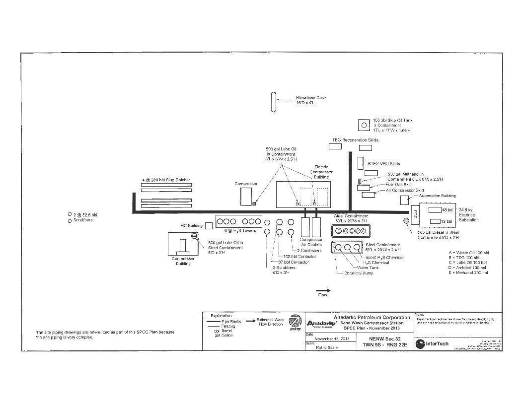
[}-
Slowdown Case 16'D x 4'L
4 @ 280 bbl Slug Catcher Compressor
D
500 gal Lube Oil in Containment
6'L x 6'W x 2.5'H
[.i:
0 [email protected] bbl 0 Scrubbers
MC Building D looo oool o
@-6@H,STowers
0
Compressor
The site piping drawings are referenced as part of this SPCC Plan because the site piping is very complex.
Building
500 gal Lube Oil in Steel Containment S'Dx 2'H
Explanation:
--- Pipe Racks -- Fencing
bbl Barrel gal Gallon
2 Scrubbers 5'D x3'H
- Estimated Water ~ Flow Direction ~'
NORTH
@] 100 bbl Slop Oil Tank in Containment 17'L x 17'Wx 1.66'H
TEG Regeneration Skids
CJ CJ
Electric Compressor
Building
D BTEX VRU Skids
CJ 500 gal Methanol in ~ Containment 6'L x 6'W x 2.5'H i=----,_----Fuel Gas Skid
____. Flow
~ Air Compressor Skid L____J LJAutomation Building
Steel Containment SO'L x 20'W x 3'H
II®@©®® 11
~ Steel Containment 59'L X 20'W X 2.4'H
Spent H,S Chemical H,S Chemical er Tank
Chemical Pump
-u CJ48 bbl 34.5 kv g Electrical
~ L c=J12 bbl Substation
\_ 500 gal Diesel in Steel Containment S'D x 2'H
A = Waste Oil 100 bbl B = TEG 100 bbl C = Lube Oil 100 bbl D = Ambitrol 100 bbl E = Methanol 200 bbl
Anadarko Petroleum Corporation An.:ad;arlq,ft Sand Wash Compressor Station
Notes Equipment connections are sho'Nrl for process direction only and are not a reflection of as·piped conditions in the field.
--- SPCC Plan - November 2013
aTe
cale November 13, 2013
Not to Scale
NENW Sec 32 TWN 9S - RNG 22E lnterTech
1,.,TKflE&E,U.C -M.\Pll:lj,tca~VW!IIN)IM)\ SancLWwl....~-~ll111J.owg

CONDENSATE/PRODUCED WATER TANK 750 bbl
(15.5' DIA.)
140'
CONDENSATE/PRODUCED WATER TANK 500 bbl
(15.5' DIA.)
q_VALUE CAN
AIR COMPRESSOR1 ~TRANSFORMERS
DEMUL.SIFIER
PIPE ABOVEGR0UNDl J crBACTERICIDE
0
c§ 0:::
(/) (/) w u ~
LEGEND
-"'v'V'v'VVv- 25" HIGH METAL BERM
.If
.. ESTIMATED SURFACE WATER FLOW DIRECTION
CONDENSATE/PRODUCED WATER TANK 650 bbl
(15.5' DIA.)
UNLOAD STATION
_)
0 <( 0 0:::
(/) (/) w u ~
""'-10
~~ SEPARATOR (60" X 10')
\ INDIRECT HEATER
STORAGE
L FIGURE 1 SITE MAP
(GLYCOL)
FILTERS
VERTICAL SEPARATOR
~
FUEL/GAS
SOUTH CENTRAL BATTERY NWNW 32-T9S-R22E UINTAH COUNTY, UTAH
KERR-t.1cGEE OIL & GAS ONSHORE LP
~ NOT TO SCALE
SC/0142-1123502

Appendix D
Emission Unit and Emission Control Descriptions

Emission Control Description
Engines
All the existing engines at this site are four stroke lean burn engines fueled by field gas. These engines are equipped with oxidation catalysts to control emissions.
Maintenance shall be performed routinely per vendor recommendations or the facility's maintenance plan. The components shall be serviced or replaced as needed.
Dehydrators
The two dehydrators (DERY 1 & DERY 2) are low emission dehydrators with emissions of less than 1.0 tpy of VOC. No further emission controls are required on these units.
Tank Battery
The Tank Battery (SC Tanks) has an enclosed flare installed. Anadarko is not claiming any credit for the control ofVOCs or HAPs.

Per the Kerr-McGee ("KMG") Consent Decree, existing and new RICE in the Uinta Basin at HAP minor sources shall be lean-burn or achieve comparable em ission reductions, and be equipped with catalyst controls (paragraphs 40 and 49). A control efficiency of 93% is required for these new and existing RICEs as per the KMG Consent Decree (paragraphs 41 and 50). Based on these federally enforceable requirements, the Antelope Flats and Sand Wash Compressor Stations is a true minor for all pollutants. Therefore AUM is only requesting the conditions of the consent decree be incorporated into a permit for this facility.
CO Emissions:
o Proposed Limit AUM is proposing the PTE for CO for all engines at the facility with a nameplate rating of 500 hp or greater shall be limited by the requirement that emissions be controlled by catalysts which meet a destruction efficiency for CO of 93% when each engine is operating at a 90% load or higher.
o Proposed testing: • Initial testing:
• Swap-out, and Like-kind Replacement Engines • Initial compliance test shall be conducted within 60 days
after achieving the maximum production rate at which the affected facility will be operated, but not later than 180 days after initial startup.
• If the catalyst fails to meet the required 93% destruction efficiency, appropriate steps shall be taken to correct the deficiency and retest the catalyst within 30 days after the initial test.
• Ongoing Testing: • All Units
Existing engines currently follow a semi-annual testing schedule per the KMG Consent Decree.
• Test Methods: • Attached Appendix F to the Consent Decree (Carbon Monoxide
Control Efficiency Portable Analyzer Monitoring Protocol) will be used to measure the 02 and CO concentrations at the inlet (pre-catalyst) and outlet (post-catalyst) of the control device using a portable analyzer. Other approved methods, not listed above, can also be used for 02 and CO analysis.
• Determine the control efficiency based on the pre- and postcatalyst CO measurements.
• Conduct one (1) test run for each performance test required. Each test run must last at least 21 minutes
• Reporting Requirements -All Engines
• Test reports shall be submitted within 60 days after each initial catalyst perfonnance test is conducted.

• Test reports for all subsequent semi-annual catalyst performance tests shall be submitted by no later than March 1 of each year for the preceding calendar year.
o Operation and Maintenance Requirements -All Engines
• The permittee shall operate and maintain each RICE and oxidation catalyst according to the catalyst manufacturer's written instructions or procedures necessary to achieve the emission reductions specified above.
Formaldehyde Emissions:
• This facility is a not major source of HAPs and is therefore not subject to the major source requirements of NESHAP Subpart ZZZZ. Therefore, no limits are being requested.
NOx Emissions:
• NOx emission is based off manufacturer's information. For the 3500 and 3600 series engines an emission factor of 2.0 g/hp-hr is used. Total facility NOx emissions are below the PSD threshold and, therefore, no engine emissions limits are being requested.
VOC Emissions:
• Caterpillar engines • Uncontrolled emissions are based on manufacturer's information and no VOC
emission reductions are being claimed from the controls of the engines. Since uncontrolled emissions are below the PSD threshold, no engine emissions limits are being requested.
• Condensate/ Produced Water Tanks • The tanks at South Central tank battery collect condensate/produced water and is
installed with an enclosed flare for emission control. Anadarko Uintah Midstream is not claiming any credit for VOCs or HAPs reduction; these tanks are represented in the application as uncontrolled.
• Low-Emission Dehydrators. • Permit Limit:
• All new and existing glycol dehydration units shall meet the following requirements.
• "Low-Emission Dehydrator shall meet the specifications set forth in Appendix C (attached) and shall mean a dehydration unit that:
o Incorporates an integral vapor recovery function such that the dehydrator cannot operate independent of the vapor recovery function;
o Either returns the captured vapors to the inlet of the facility where such dehydrator is located or routes the captured vapors to that facility's fuel gas supply header; and

o Has a PTE less than 1.0 TPY ofVOCs, inclusive of VOC emissions from the reboiler burner.
• Existing Units • Attached Appendix C to the Consent Decree documents Low Emission
Dehydrator specifications to ensure the existing units meet the requirements above.
• Reporting • Written notification to EPA within 60 Days of each installation of a new
Low-Emission Dehydrator, and include a description of the equipment installed and a certification that the Low-Emission Dehydrator meets the criteria set forth in this permit. The certification shall be signed by a Responsible Official or by a delegated employee representative, unless otherwise required by applicable statute or regulation. All reports and submissions shall include the following certification:
I certify under penalty of law that this document and all attachments were prepared under my direction or supervision in accordance with a system designed to assure that qualified personnel properly gather and evaluate the information submitted. Based on my inquiry of the person or persons who manage the system, or those persons directly responsible for gathering the information, the information submitted is, to the best of my knowledge and belief, true, accurate and complete.
• Recordkeeping • Shall maintain records and information adequate to demonstrate its
compliance with the requirements of this permit for five years.
• Pneumatic Controllers • Perm it Lim it:
• All pneumatic controllers shall be operated on instrument air or shall be low-bleed or no-bleed gas operated pneumatic controllers.

Attachment - CD Appendix F
Carbon Monoxide Control Efficiency Portable Analyzer Monitoring Protocol

APPENDIXF
to the
Consent Decree
in the matter of
United States of America and the State of Colorado v. Kerr-McGee Corporation
CARBON MONOXIDE CONTROL EFFICIENCY PORTABLE ANALYZER MONITORING PROTOCOL
Determination of Carbon Monoxide Control Efficiency from Controlled Natural Gas-Fired Reciprocating Engines Located in the Uinta Basin

TABLE OF CONTENTS
1. APPLICABILITY AND PRINCIPLE ..... ............................ .. ............................... ......... ....... 1 1.1 Applicability ..... ..... ....... ...................................... ..... ............................... ......... .......... 1 1.2 Principle ....................................................................................... ................... ........... 1
2. RANGE AND SENSITIVITY ............. .. ...................... ........ .... ............................... .... ... ..... .... 2 2.1 Analytical Range ...................... .............. ... ............................................ ..... ............... 2
3. DEFINITIONS .......................... ......... ............ ... .. ..... ............ ....... ....... ................. ....... ..... ........ 3 3.1 Measurement System .... .......................... .... ........................ ........ .............................. 3 3.2 Nominal Range .... .... ... ................................ ... ...................... ......... ..... ........................ 3 3.3 Span Gas .................. ..... .......... ............ .... ...... ............................................................. 3 3.4 Zero Calibration Error ........ ...... ........................ ........................ ..... .. .. ........ .......... ... . 3 3.5 Span Calibration Error .. .................. ... ................ ....... ... ....... ..... ........... .................... 4 3.6 Response Time .......................... .......... ... ..................... ........ ..... ........ ....... .......... ......... 4 3.7 Linearity Check ... ................................... ..... ................................ .. .. ...... .................. .. 4 3.8 Stability Check .... .................. ................ .. ............. ........ .... .. ....................................... 4 3.9 Stability Time .. ...... ............ ... .. ............. ... .... .... ........ ....... ............ ................................ 4 3.10 Test ................ ................................ .. .. ........ ........ ..................................... ... ........... .... 4
4. MEASUREMENT SYSTEM PERFORMANCE SPECIFICATIONS ....... ....................... 5 4.1 Zero Calibration Error ............... ... ... ................. ........... ............................................ 5 4.2 Span Calibration Error .. .................. ...................... ... ......... ........ ... ........................... 5 4.3 Linearity .............. ................................. ......................... ..... .... ........ ........ .................... 5 4.4 Stability Check Response ..................... ..... ............... ... ............. ... ............. .... ............ 5 4.5 CO Measurement, Hydrogen (H2) Compensation ...... ........... ..... ..... ....... ............... 5
5. APPARATUS AND REAGENTS ...................... ....................... ...... ........ .... .............. ... .......... 6 5.1 Measurement System ............. .... ................... .... ...... ........ ........... ..... ....... ..... .............. 6 5.2 Calibration Gases .............................. ............................ ......... ..... ..... ........... .... .......... 7
6. MEASUREMENT SYSTEM PERFORMANCE CHECK PROCEDURES ............... .... . 9 6.1 Calibration Gas Concentration Certification ............ .... ........ .... ....... ...................... 9 6.2 Linearity Check ...... .. .............. ....................... .... ..... ........... .... .................................... 9 6.3 Stability Check ................................ ... ... ... ... .............. ..... ......... .... .............................. 9 6.4 Interference Check .. ....................................... ....... ..... ........ ........ ....... ...................... 10
7. EMISSION TEST PROCEDURES ........................... ....... ...... ...................................... ....... 11 7.1 Pre/Post Catalyst Sampling ....... ............ ..................................... .. .......................... 11 7.2 Warm Up Period ... ....................................... ...... ........... .... ............ .. ........................ 11 7 .3 Pretest Calibration Error Check .......... ....... ... ............... ......... .............. ............... .. 11 7.4 Sample Collection ............................. .......... ............ .... .......... ........ .... ........... .... ... ..... 12 7.5 Re-Zero ........... ...... ....... .... .......... ....... .......... ... ... ............ .... .... ................. .. ........... ..... 12
8. DATA COLLECTION .... ...................... ............. ......... .......... ..... ............ .. ... ...... ... ................ 13 8.1 Linearity Check Data ............... ....... ..................................... .................................. 13 8.2 Stability Check Data ............. ................... ......... ........ ...... .......... ..... ........... .... ..... ..... 13 8.3 Pretest Calibration Error Check Data ..................... ..... ........ ..... ........................... 13 8.4 Test Data ................................................................................ ..... ......... .. ... ..... .......... 13
9. CONTROL EFFICIENCY CALCULATIONS .... ................ ..... ........................................ 14 9.1 Control Efficiency Calculations ................................................. ............................. 14

9.2 Interference Check Calculations ........ .......... .. ....... ................. ......... ........ ............... 14 10. REPORTING REQUIREMENTS AND RECORD KEEPING REQUIREMENTS ... 15

OVERVIEW AND PURPOSE
Kerr-McGee has agreed to conduct portable analyzer testing for carbon monoxide ("CO") on
certain reciprocating internal combustion engines ("RICE") located in the Uinta Basin that are
controlled with oxidation catalysts as part of a settlement of alleged Clean Air Act violations
with the United States and the State of Colorado. The terms of that settlement will be
memorialized in a consent decree to be entered by the United States District Court for the District
of Colorado to be styled United States of America and the State of Colorado v. Kerr-McGee
Corporation (hereafter the "Consent Decree"). As required in the Consent Decree at Section
IV.D., Kerr-McGee will conduct portable analyzer testing on certain RICE located in the Uinta
Basin that will be controlled with oxidation catalysts.
1. APPLICABILITY AND PRINCIPLE
1.1 Applicability. This protocol was prepared to be implemented by Kerr-McGee Oil and Gas
Onshore LP, Westport Field Services LLC and/or certain of their corporate affiliates ("Kerr-McGee")
will monitor carbon monoxide (CO) and oxygen (02) concentrations from controlled natural gas
fired reciprocating engines using portable analyzers with electrochemical cells.
1.2 Principle. A gas sample is continuously extracted from a stack and conveyed to a portable
analyzer for determination of CO and 0 2 gas concentrations using electrochemical cells. Analyzer
design specifications, performance specifications, and test procedures are provided to ensure reliable
data. Additions to or modifications of vendor-supplied analyzers (e.g. heated sample line, flow
meters, etc.) may be required to meet the design specifications of this test method.
Appendix F: Carbon Monoxide Control Efficiency Portable Analyzer Monitoring Protocol Page 1

2. RANGE AND SENSITIVITY
2.1 Analytical Range. The analytical range for each gas component is determined by the
electrochemical cell design. A portion of the analytical range is selected to be the nominal range by
choosing a span gas concentration near the flue gas concentrations or permitted emission level in
accordance with Sections 2.1.1 and 2.1.2.
2.1.1 CO Span Gas. Choose a CO span gas such that the concentration is approximately 1.25 times
average expected pre-catalyst stack gas reading.
2.1.2 0 2 Span Gas. The 0 2 span gas shall be dry ambient air at 20.9% 0 2.
2.1.2 NO Span Gas. The NO span gas shall be approximately 250 ppm.
Appendix F: Carbon Monoxide Control Efficiency Portable Analyzer Monitoring Protocol Page 2

3. DEFINITIONS
3.1 Measurement System. The total equipment required for the determination of gas
concentration. The measurement system consists of the following major subsystems:
3.1.1 Sample Interface. That portion of a system used for one or more of the following: sample
acquisition, sample transport, sample conditioning, or protection of the electrochemical cells from
particulate matter and condensed moisture.
3.1.2 External Interference Gas Scrubber. A tube filled with scrubbing agent used to remove
interfering compounds upstream of some electrochemical cells.
3.1.3 Electrochemical (EC) Cell. The portion of the system that senses the gas to be measured and
generates an output proportional to its concentration. Any cell that uses diffusion-limited oxidation
and reduction reactions to produce an electrical potential between a sensing electrode and a counter
electrode.
3.1.4 Data Recorder. It is recommended that the analyzers be equipped with a strip chart recorder,
computer, or digital recorder for recording measurement data. However, the operator may record the
test results manually in accordance with the requirements of Section 7.4.
3.2 Nominal Range. The range of concentrations over which each cell is operated (25 to 125
percent of span gas value). Several nominal ranges may be used for any given cell as long as the
linearity and stability check results remain within specification.
3.3 Span Gas. The high level concentration gas chosen for each nominal range.
3.4 Zero Calibration Error. For the CO channel, the absolute value of the difference, expressed as
a percent of the span gas, between the gas concentration exhibited by the gas analyzer when a zero
level calibration gas is introduced to the analyzer and the known concentration of the zero level
Appendix F: Carbon Monoxide Control Efficiency Portable Analyzer Monitoring Protocol Page 3

calibration gas. For the 0 2 channel, the difference, expressed as percent 0 2, between the gas
concentration exhibited by the gas analyzer when a zero level calibration gas is introduced to the
analyzer and the known concentration of the zero level calibration gas.
3.5 Span Calibration Error. For the CO channel, the absolute value of the difference, expressed as
a percent of the span gas, between the gas concentration exhibited by the gas analyzer when a span
gas is introduced to the analyzer and the known concentration of the span gas. For the 0 2 channel,
the difference, expressed as percent 0 2, between the gas concentration exhibited by the gas analyzer
when a span gas is introduced to the analyzer and the known concentration of the span gas.
3.6 Response Time. The amount of time required for the measurement system to display 95 percent
of a step change in the CO gas concentration on the data recorder.
3.7 Linearity Check. A method of demonstrating the ability of a gas analyzer to respond
consistently over a range of gas concentrations.
3.8 Stability Check. A method of demonstrating an electrochemical cell operated over a given
nominal range provides a stable response and is not significantly affected by prolonged exposure to
the analyte.
3.9 Stability Time. As determined during the stability check; the elapsed time from the start of the
gas injection until a stable reading has been achieved.
3.10 Test. The collection of emissions data consisting of two consecutive 21 minute sampling
periods, 21 minutes pre-catalyst and 21 minutes post catalyst, from each source.
Appendix F: Carbon Monoxide Control Efficiency Portable Analyzer Monitoring Protocol Page4

4. MEASUREMENT SYSTEM PERFORMANCE SPECIFICATIONS
4.1 Zero Calibration Error. Less than or equal to ±3 percent of the span gas value for CO
channels and less than or equal to ±0.3 percent 0 2 for the 0 2 channel.
4.2 Span Calibration Error. Less than or equal to ±5 percent of the span gas value for CO
channels and less than or equal to ±0.5 percent 0 2 for the 0 2 channel.
4.3 Linearity. For the zero, mid-level, and span gases, the absolute value of the difference,
expressed as a percent of the span gas, between the gas value and the analyzer response shall not be
greater than 2.5 percent for the CO cell.
4.4 Stability Check Response. The analyzer responses to CO span gases shall not vary more than
3.0 percent of span gas value over a 30-minute period or more than 2.0 percent of the span gas value
over a 15-minute period.
4.5 CO Measurement, Hydrogen (H2) Compensation. It is recommended that CO measurements
be performed using a hydrogen-compensated EC cell since CO-measuring EC cells can experience
significant reaction to the presence of H2 in the gas stream. Sampling systems equipped with a
scrubbing agent prior to the CO cell to remove H2 interferent gases may also be used.
Appendix F: Carbon Monoxide Control Efficiency Portable Analyzer Monitoring Protocol Page 5

5. APPARATUS AND REAGENTS
5.1 Measurement System. Use any measurement system that meets the performance and design
specifications in Sections 4 and 5 of this method. The sampling system shall maintain the gas
sample at a temperature above the dew point up to the moisture removal system. The sample
conditioning system shall be designed so there are no entrained water droplets in the gas sample
when it contacts the electrochemical cells. A schematic of an acceptable measurement system is
shown in Figure 1. The essential components of the measurement system are described below:
5.1.1 Sample Probe. Glass, stainless steel, or other nonreactive material, of sufficient length to
sample per the requirements of Section 7. If necessary to prevent condensation, the sampling probe
shall be heated.
5.1.2 Heated Sample Line. Heated (sufficient to prevent condensation) nonreactive tubing such as
teflon, stainless steel, glass, etc. to transport the sample gas to the moisture removal system.
(Includes any particulate filters prior to the moisture removal system.)
5.1.3 Sample Transport Lines. Nonreactive tubing such as teflon, stainless steel, glass, etc. to
transport the sample from the moisture removal system to the sample pump, sample flow rate
control, and electrochemical cells.
5.1.4 Calibration Assembly. A tee fitting to attach to the probe tip or where the probe attaches to
the sample line for introducing calibration gases at ambient pressure during the calibration error
checks. The vented end of the tee should have a flow indicator to ensure sufficient calibration gas
flow. Alternatively use any other method that introduces calibration gases at the probe at
atmospheric pressure.
5.1.5 Moisture Removal System. A chilled condenser or similar device (e.g., permeation dryer) to
remove condensate continuously from the sample gas while maintaining minimal contact between
the condensate and the sample gas.
Appendix F: Carbon Monoxide Control Efficiency Portable Analyzer Monitoring Protocol Page 6

5.1.6 Particulate Filter. Filters at the probe or the inlet or outlet of the moisture removal system
and inlet of the analyzer may be used to prevent accumulation of particulate material in the
measurement system and extend the useful life of the components. All filters shall be fabricated of
materials that are nonreactive to the gas being sampled.
5.1.7 Sample Pump. A leak-free pump to pull the sample gas through the system at a flow rate
sufficient to minimize the response time of the measurement system. The pump may be constructed
of any material that is nonreactive to the gas being sampled.
5.1.8 Sample Flow Rate Control. A sample flow rate control valve and rotameter, or equivalent, to
maintain a constant sampling rate within 10 percent during sampling and calibration error checks.
The components shall be fabricated of materials that are nonreactive to the gas being sampled.
5.1.9 Gas Analyzer. A device containing electrochemical cells to determine the CO and 0 2
concentrations in the sample gas stream. The analyzer shall meet the applicable performance
specifications of Section 4. A means of controlling the analyzer flow rate and a device for
determining proper sample flow rate (e.g., precision rotameter, pressure gauge downstream of all
flow controls, etc.) shall be provided at the analyzer.
5.1.10 Data Recorder. A strip chart recorder, computer, or digital recorder, for recording
measurement data. The data recorder resolution (i .e., readability) shall be at least 1 ppm for CO and
0.1 percent 0 2 for 0 2 ; and one degree (C or F) for temperature.
5.1.11 External Interference Gas Scrubber. Used by some analyzers to remove interfering
compounds upstream of a CO electrochemical cell. The scrubbing agent should be visible and
should have a means of determining when the agent is exhausted (e.g., color indication).
5.2 Calibration Gases. Both the CO and NO calibration gases for the gas analyzer shall be CO or
Appendix F: Carbon Monoxide Control Efficiency Portable Analyzer Monitoring Protocol Page 7

NO in nitrogen.
5.2.1 Span Gases. Used for calibration error, linearity, and interference checks of each nominal
range of each eel l. Select concentrations according to procedures in Section 2.1.1 . Clean dry air may
be used as the span gas for the 0 2 cell as specified in Section 2.1.2.
5.2.2 Mid-Level Gases. Select concentrations that are 40-60 percent of the span gas concentrations.
5.2.3 Zero Gas. Concentration of less than 0.25 percent of the span gas for each component.
Ambient air may be used in a well ventilated area for the CO.
Appendix F: Carbon Monoxide Control Efficiency Portable Analyzer Monitoring Protocol Page 8
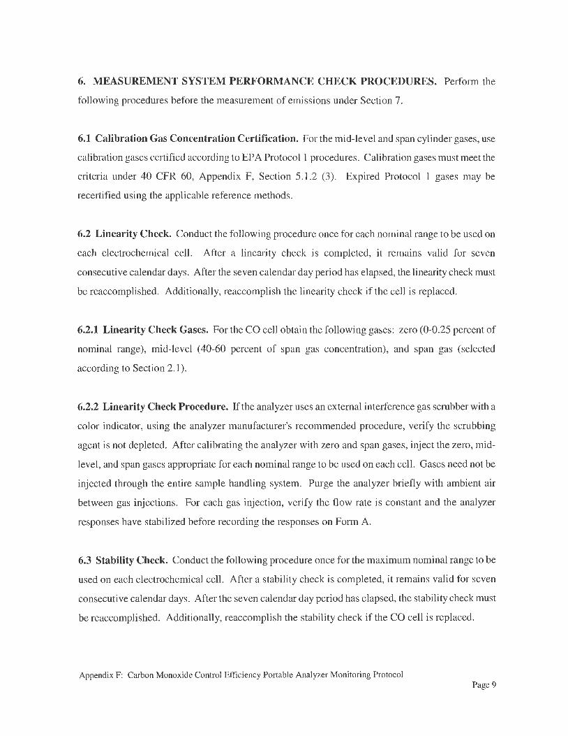
6. MEASUREMENT SYSTEM PERFORMANCE CHECK PROCEDURES. Perform the
following procedures before the measurement of emissions under Section 7.
6.1 Calibration Gas Concentration Certification. For the mid-level and span cylinder gases, use
calibration gases certified according to EPA Protocol I procedures. Calibration gases must meet the
criteria under 40 CFR 60, Appendix F, Section 5.1.2 (3). Expired Protocol 1 gases may be
recertified using the applicable reference methods.
6.2 Linearity Check. Conduct the following procedure once for each nominal range to be used on
each electrochemical cell. After a linearity check is completed, it remains valid for seven
consecutive calendar days. After the seven calendar day period has elapsed, the linearity check must
be reaccomplished. Additionally, reaccomplish the linearity check if the cell is replaced.
6.2.1 Linearity Check Gases. For the CO cell obtain the following gases: zero (0-0.25 percent of
nominal range), mid-level (40-60 percent of span gas concentration), and span gas (selected
according to Section 2.1).
6.2.2 Linearity Check Procedure. If the analyzer uses an external interference gas scrubber with a
color indicator, using the analyzer manufacturer's recommended procedure, verify the scrubbing
agent is not depleted. After calibrating the analyzer with zero and span gases, inject the zero, mid
level, and span gases appropriate for each nominal range to be used on each cell. Gases need not be
injected through the entire sample handling system. Purge the analyzer briefly with ambient air
between gas injections. For each gas injection, verify the flow rate is constant and the analyzer
responses have stabilized before recording the responses on Form A.
6.3 Stability Check. Conduct the following procedure once for the maximum nominal range to be
used on each electrochemical cell. After a stability check is completed, it remains valid for seven
consecutive calendar days. After the seven calendar day period has elapsed, the stability check must
be reaccomplished. Additionally, reaccomplish the stability check if the CO cell is replaced.
Appendix F: Carbon Monoxide Control Efficiency Portable Analyzer Monitoring Protocol Page 9

6.3.1 Stability Check Procedure. Inject the CO span gas for the maximum nominal range to be
used during the emission testing into the analyzer and record the analyzer response at least once per
minute until the conclusion of the stability check. One-minute average values may be used instead of
instantaneous readings. After the analyzer response has stabilized, continue to flow the span gas for
at least a 30-minute stability check period. Make no adjustments to the analyzer during the stability
check except to maintain constant flow. Record the stability time as the number of minutes elapsed
between the start of the gas injection and the start of the 30-minute stability check period. As an
alternative, if the concentration reaches a peak value within five minutes, you may choose to record
the data for at least a 15-minute stability check period following the peak.
6.3.2 Stability Check Calculations. Determine the highest and lowest CO concentrations recorded
during the 30-minute period and record the results on Form B. The absolute value of the difference
between the maximum and minimum values recorded during the 30-minute period must be less than
3.0 percent of the span gas concentration. Alternatively, record stability check data in the same
manner for the 15-minute period following the peak concentration. The difference between the
maximum and minimum values for the 15-minute period must be less than 2.0 percent of the span
gas concentration.
6.4 Interference Check. Conduct the following procedure once for the average anticipated NO
stack gas concentration as reported by the manufacuture (250 ppm for Caterpillar lean bums). After
a interference check is completed, this value will be utilized for interference calculations for the next
7 calendar days. After the seven calendar day period has elapsed, the interference check must be
reaccomplished.
6.4.1 Interference Check Procedure. Inject the 250 ppm NO span gas for the into the analyzer and
record the analyzer response at least once per minute until the conclusion of the interference check.
One-minute average values may be used instead of instantaneous readings. After the analyzer
response has stabilized, continue to flow the span gas for at least a 15-minute period. Make no
adjustments to the analyzer during the stability check except to maintain constant flow. Record the
CO cell response to this NO calibration gas.
Appendix F: Carbon Monoxide Control Efficiency Portable Analyzer Monitoring Protocol Page 10

7. EMISSION TEST PROCEDURES.
Prior to performing the following emission test procedures, calibrate/challenge all electrochemical
cells in the analyzer in accordance with the manufacturer's instructions.
7.1. Pre/Post-Catalyst Sampling. Select both a pre-catalyst and post catalyst sampling site that
will provide continuous unintetTUpted exhaust gas flow.
7.2 Warm Up Period. Assemble the sampling system and allow the analyzer and sample interface
to warm up and adjust to ambient temperature at the location where the stack measurements will take
place.
7.3 Pretest Calibration Error Check. Conduct a zero and span calibration error check before
testing each new facility. Conduct the calibration error check near the sampling location just prior to
the start of the first emissions test.
7.3.1 Scrubber Inspection. For analyzers that use an external interference gas scrubber tube,
inspect the condition of the scrubbing agent and ensure it will not be exhausted during sampling. If
scrubbing agents are recommended by the manufacturer, they should be in place during all sampling,
calibration and performance checks.
7.3.2 Zero and Span Procedures. Inject the zero and span gases using the calibration assembly.
Ensure the calibration gases flow through all parts of the sample interface. During this check, make
no adjustments to the system except those necessary to achieve the correct calibration gas flow rate at
the analyzer. Set the analyzer flow rate to the value recommended by the analyzer manufacturer.
Allow each reading to stabilize before recording the result on Form C. The time allowed for the span
gas to stabilize shall be no less than the stability time noted during the stability check. After
achieving a stable response, disconnect the gas and briefly purge with ambient air.
7.3.3 Response Time Determination. Determine the CO response time by observing the time
required to respond to 95 percent of a step change in the analyzer response for both the zero and span
Appendix F: Carbon Monoxide Control Efficiency Portable Analyzer Monitoring Protocol Page 11

gases. Note the longer of the two times as the response time.
7.3.4 Failed Pretest Calibration Error Check. If the zero and span calibration error check results
are not within the specifications in Section 4, take corrective action and repeat the calibration error
check until acceptable performance is achieved.
7.4 Sample Collection. Position the sampling probe at the pre-catalyst sample point and begin
sampling at the same rate used during the calibration error check. Maintain constant rate sampling
(± 10 percent of the analyzer flow rate value used in Section 7 .3.2) during the entire test. The
concentration data must be recorded either (1) at least once each minute, or (2) as a block average for
the test using values sampled at least once each minute. Repeat this procedure from the post-catalyst
sampling location. Two consecutive 21 minute samples, one pre-catalyst and one post catalyst, shall
be considered a test for each source
7.5 Re-Zero. At least once every four hours, recalibrate the analyzer at the zero level according to
the manufacturer's instructions and conduct a pretest calibration error check before resuming
sampling. If the analyzer is capable of reporting negative concentration data ( at least 5 percent of the
span gas below zero), then the tester is not required to re-zero the analyzer.
Appendix F: Carbon Monoxide Control Efficiency Portable Analyzer Monitoring Protocol Page 12

8. DATA COLLECTION. This section summarizes the data collection requirements for thi s
protocol.
8.1 Linearity Check Data. Using Form A, record the analyzer responses in ppm for CO, and
percent 0 2 for the zero, mid-level, and span gases injected during the linearity check under Section
6.2.2.
8.2 Stability Check Data. Record the analyzer response in pmm for CO at least once per minute
during the stabi lity check under Section 6.3.1. One-minute average values may be used instead of
instantaneous readings. Record the stability time as the number of minutes elapsed between the start
of the gas injection and the start of the 30-minute stability check period. If the concentration reaches
a peak value within five minutes of the gas injection, you may choose to record the data for at least a
15-minute stability check period following the peak. Use the information recorded to determine the
analyzer stability under Section 6.3 .2.
8.3 Pretest Calibration Error Check Data. On Form C, record the analyzer responses to the zero
and span gases for CO and 0 2 injected prior to testing each new source. Record the calibration zero
and span gas concentrations for CO and 0 2. For CO, record the absolute difference between the
analyzer response and the calibration gas concentration, divide by the span gas concentration, and
multiply by 100 to obtain the percent of span. For 0 2, record the absolute value of the difference
between the analyzer response and the 0 2 calibration gas concentration. Record whether the
calibration is valid by comparing the percent of span or difference between the calibration gas
concentration and analyzer 0 2 response, as applicable, with the specifications under Section 4.1 for
the zero calibrations and Section 4.2 for the span calibrations. Record the response times for the CO
zero and span gases as described under Section 7.3.3. Select the longer of the two times as the
response time for that pollutant.
8.4 Test Data. On Form D-1 record the source operating parameters dming the test. Record the test
start and end times. From the analyzer responses recorded each minute during the test, obtain the
average flue gas concentration of each pollutant.
Appendix F: Carbon Monoxide Control Efficiency Portable Analyzer Monitoring Protocol Page 13

9. CONTROL EFFICIENCY CALCULATIONS
9.1 Control Efficiency Calculations. CO control efficiencies will be calculated using the
following calculation:
% Control (C - Cpos1 ) 100 pre X
C pre
where:% control = actual control efficiency of the oxidation catalyst
CPre = stack gas concentration at the pre-catalyst sampling location (ppm)
Cpost = stack gas concentration at the post-catalyst sampling location (ppm)
9.2 Interference Check. Utilize the data collected in Section 6.3.4 and the average pre-catalyst
CO emission concentrations to calculate interference responses (Ico) for the CO cell. If an
interference response exceeds 5 percent, all emission test results since the last successful
interference test for that compound are invalid.
9.2.1 CO Interference Calculation.
I co= [(Rea-No)( C Nos )]xJOO C NoG Ccos
where: Ico = CO interference response (percent)
Rco-No = CO response to NO span gas (ppm CO)
CNoG = concentration of NO span gas (ppm NO)
CNos = Anticipated concentration of NO in stack gas (250 ppm NO)
Ccos = concentration of CO in stack gas (ppm CO)
Appendix F: Carbon Monoxide Control Efficiency Portable Analyzer Monitoring Protocol Page 14

10. REPORTING REQUIREMENTS AND RECORD KEEPING REQUIREMENTS
Test reports shall be submitted to the Environmental Protection Agency (EPA), as required by
Section IV C of Consent Decree, within thirty (30) days of completing the test. A separate test
report shall be submitted for each facility where an emission source was tested and, at a minimum,
the following information shall be included:
Form A, Linearity/Interference Check Data Sheet, Submit the
linearity check as required by Section 6.2 for the nominal range tested .
Form B, Stability Check Data Sheet, Submit the stability check as
required by Section 6.4 for the nominal range tested .
Form C, Calibration Error Check Data Sheet
Form D-1, Submit the appropriate test results form.
Records pertaining to the information above and supporting documentation shall be kept for five (5)
years and made available upon request by EPA. Additionally, if the source is equipped with a fuel
meter, records of all maintenance and calibrations of the fuel meter shall be kept for five (5) years
from the date of the last maintenance or calibration.
Appendix F: Carbon Monoxide Control Efficiency Portable Analyzer Monitoring Protocol Page 15

FormA
Linearity/Interference Check Data Sheet
Date: _____ _
Analyst: _______________ _
Analyzer Manufacturer/Model#: ___________________ _
Analyzer Serial#: __________________ _
Calibration Gas Analyzer Absolute Linearity Analyzer Percent of
Pollutant Concentration Response Difference Valid Response % 0 2 Span
(ppm) {ppm CO) {ppm) (Yes or No)
Zero
co Mid
Span
NO Span
April 7, 2007

FormB Stability Check Data Sheet
Date:_______ Analyst: ______________________ _ Analyzer Manufacturer/Model#: _________________________ _
Analyzer Serial#: __________________ _
Pollutant: CO Span Gas Concentration (ppm): ______ _
STABILITY CHECK Elapsed
Analyzer Elapsed
Analyzer Elapsed
Analyzer Time Time Time (Minutes)
Response (Continued)
Response (Continued)
Response
1 17 33
2 18 34
3 19 35
4 20 36
5 21 37
6 22 38
7 23 39
8 24 40
9 25 41
10 26 42
11 27 43
12 28 44
13 29 45
14 30 46
15 31 47
16 32 48
For 30-minute Stability Check Period:
Maximum Concentration (ppm): Minimum Concentration (ppm):
For IS-minute Stability Check Period:
Maximum Concentration (ppm): Minimum Concentration (ppm):
Maximum Deviation = lO0*(Max. Cone. - Min. Conc.)/Span Gas Cone. =
Stability Time (minutes):
April 7, 2007
percent

FormC Calibration Error Check Data Sheet Company: _____________ _ Facility: ________________ _
Source Tested: ___________ _ Date: _________________ _
Analyst: _______________ _ Analyzer Serial#: ____________ _
Analyzer Manufacturer/Model#: _____________________________ _
PRETEST CALIBRATION ERROR CHECK
A B IA-Bl IA-BI tSG*lO0
Pump Flow Analyzer Calibration Gas Absolute Rate (Indicate Reading Concentration Difference Percent of Span Calibration Valid Response Time
Units) (Indicate Units) (Indicate Units) (Indicate Units) Note 1 (Yes or No) (Minutes)
co Zero
Span
o, Zero
Span
SG = Span Gas
April 7, 2007

Form D-1 Reciprocating Engine Test Results
Company: _______________ _ Facility: ________________ _
Source Tested: _____________ _ Date: ----------------Source Manufacturer/Model#: _______________________________ _
Site-rated Horsepower: __________ _ Source Serial#:. _____________ _
Type of Emission Control: _______________________________ _
Analyst: _______________ _ Analyzer Serial#: ____________ _
Analyzer Manufacturer/Model#: _____________________________ _
Operating Conditions Source operating at 90 percent or greater site-rated horsepower during testing? yes no
Engine Tested Engine Fuel Engine Specific Fuel Fuel Heat Content Horsepower Engine RPM Consumption
(Btu/cf) Consumption
(hp)
1 As reported by the Manufacturer
Test Results Test Start Time: ____ _
02
Avg. Tested Avg. Pre-
02 % Catalyst CO ppm
(Indicate Units) (Btu/hp-hr)1
__Test End Time: __________________ _
co
Avg. Post- Tested Required CO Interference
Catalyst CO Reduction Response
CO ppm CO Reduction ( % ) (%) Cico,%):
93%
I certify to the best of my knowledge the test results are accurate and representative of the emissions from this source.
Print Name Signature
April 7, 2007

APPENDIX C
to the
Consent Decree
in the matter of
United States of America and the State of Colorado v. Kerr-McGee Corporation
LOW-EMISSION DEHYDRATOR SPECIFICATIONS

Overview and Purpose
Kerr-McGee has agreed to employ "Low-Emission Dehydrator" technology at its existing and planned facilities in the Uinta Basin as part of the settlement of alleged Clean Air Act violations with the United States and the State of Colorado. The terms of that settlement will be memorialized in a consent decree to be entered by the United States District Court for the District of Colorado to be styled United States of America and the State of Colorado v. Kerr-McGee Corporation (hereafter the "Consent Decree"). As required in the Consent Decree at Section IV.A. , this Appendix C includes:
(a) a description of physical electrical hard-wiring between the vapor recovery unit ("VRU") compressor(s) and the glycol circulation pumps employed or to be employed, so that if the VRU compressor(s) go down then the glycol circulation pump(s) also shut down, thereby halting the circulation of glycol through the wet gas, as well as the emissions associated with the regeneration of the glycol;
(b) a description of a second level of protection (redundancy) incorporated into a Programmable Logic Controller that uses instrumentation to shut down the glycol dehydration system in the event all VRU compressor(s) go down; and
(c) a description of any third level of protection and discussion of how the noncondensible gases from glycol dehydrator operation shall be piped exclusively to the station inlet or fuel system for use as fuel and is not used for blanket gas in storage tanks or otherwise vented.
Background
Natural gas often contains water vapor at the wellhead which must be removed to avoid pipeline corrosion and solid hydrate formation. Glycol dehydration is the most widely used natural gas dehumidification process. In a glycol dehydration system, dry triethylene glycol ("TEG") or ethylene glycol ("EG") is contacted with wet natural gas. The glycol absorbs water from the natural gas, but also absorbs hydrocarbons including volatile organic compounds ("VOCs") and certain hazardous air pollutants ("HAPs"). Pumps circulate the glycol from a low-pressure distillation column for regeneration back to high pressure in order to contact with the high pressure wet gas. As the wet glycol pressure is reduced prior to distillation, much of the absorbed hydrocarbon is released, including some of the VOCs and HAPs. A flash tank is typically utilized to separate these vapors at a pressure where they can be utilized for fuel. Distillation removes the absorbed water along with any remaining hydrocarbon, including VOCs and HAPs, from the glycol to the still column vent as overhead vapor. Conventional dehydrator still columns often emit the non-condensable portion of this overhead vapor directly to the atmosphere, or to a combustion device such as a thermal oxidizer or reboiler burner.
Kerr-McGee currently utilizes low-emission glycol dehydrators at its facilities in the Uinta Basin. These units capture the non-condensable portion of still vent and flash tank vapors and recompress the vapor with reciprocating or scroll compressors that route the
Appendix C: Low Emission Dehydrator Specifications Page 1

vapor to the station inlet as natural gas product, to fuel lines for power generation turbines or to the station fuel system. They also employ electric glycol circulation pumps, and except for the recompression of non-condensable vapors, resemble conventional glycol dehydrators in their configuration. See Figure 1.
To insure that the non-condensable vapor compression system is fully integrated into dehydrator operation such that the units cannot be disabled so as to operate while venting to the atmosphere, each unit;
a. incorporates an integral vapor recovery function that prevents the dehydrator from operating independent of the vapor recovery function;
b. either returns the captured vapors to the inlet of the facility where each glycol dehydrator is located or routes the captured vapors to that facility's fuel gas supply header; and
c. thereby emits no more than 1.0 ton per year of VOCs.
Description of Interlocks
The low-emission glycol dehydrators have at least three (3) levels of protection to prevent emissions from occurring.
(a) Physical electrical hard-wiring between the vapor recovery unit (VRU) compressor(s) and the glycol circulation pumps ensures that if the VRU compressor(s) goes down, the glycol pump(s) also shut down, thereby halting the circulation of glycol through the wet gas as well as the emissions associated with the regeneration of glycol. More specifically:
1. Loss of station power inten-upts the 480 volt power to the glycol pump(s) circulating glycol through the contactor.
2. Loss of 24 volt power to a relay interrupts the 480 volt power to the glycol pump(s) circulating glycol through the contactor. The 24 volt power is wired in parallel through the run status contacts of each VRU compressor in a specific service. If all VRU compressors in each specific service are shutdown, the 24 volt power is interrupted. There is at least one spare VRU compressor in standby mode for each specific service at existing Uinta Basin facilities engaged in gas dehydration. Non-condensable gas from VRU compressor discharge always has an outlet because if the station inlet pressure rises to a level greater than VRU compressor output, the flash tank vapors automatically go through a back pressure regulator to the fuel gas system until gathering pressure is reduced.
3. If the glycol still column/reboiler pressure rises above pressure set points, the 24 volt power to a relay is interrupted. The unpowered relay interrupts the 480 volt power to the glycol pump(s) circulating glycol to the contactor. If one of the glycol still VRU compressors is running but not compressing vapors, the pressure switch will detect the pressure rise in the still and shutdown the glycol circulating pump(s).
Appendix C: Low Emission Dehydrator Specifications Page 2

4. The operation of at least one of the VRU compressors is required to complete the electrical circuit and allow one of the glycol circulation pumps to operate.
5. There is a 10 second time delay switch installed in the physical electrical circuit that must time out before the glycol circulating pump(s) shut down for causes 2 and 3 above. This allows for switching of compressors and helps to prevent false shutdowns.
6. Everything is hard wired and does not depend on any type of controller.
(b) A second level of protection redundancy has been incorporated by utilizing the station Programmable Logic Controller (PLC) to shut down the dehydration system in the event the VRU compressor(s) go down.
I . A PLC timer will start counting when none of the VRU compressor(s) are in operation. When the timer times out, the PLC will not allow the regenerator system to be in run status.
(c) A third level of protection is the routing of non-condensables directly to combustion devices in the stations that utilize micro-turbine electrical generators or central heat medium systems.
I. The non-condensable regenerator overhead vapors are routed to the inlet of each station or used as fuel. In instances where the inlet pressure rises above VRU compressor outlet pressures, a regulator opens allowing the VRU-compressed vapors to be discharged into the fuel system, where they are used throughout the station.
2. In Kerr-McGee's planned electrified compressor stations, liquids that condense at the compression stations, including those condensed from the glycol still overhead vapors, will be contained at pressure, separated from any water and pumped downstream into the high pressure gathering system. This process change will eliminate atmospheric storage of hydrocarbon liquids at such facilities .
Conclusion
Kerr-McGee's adherence to these specifications shall satisfy its commitment in the Consent Decree to utilize low-emission dehydrator technology in its existing and planned Uinta Basin operations.
Appendix C: Low Emission Dehydrator Specifications Page 3

Contactor
,Inlet Gas;---"·1 1 II U
Figure 1: Kerr-McGee Low-Emission Dehydrator Schematic
Glycol Dehydration Unit
Glycol Pump
----------17'------l =lae< "'""" o, Foal I"':
~Non-Condensables 20 Y al HX-Dry Gas------
------Lean TE
I ·Pump Hp----J
Overhead Compressor
r~ Overhead Condenser
Wate'r Gas OverheadlSeoarator Condensables
--------------------------------- a-100---------------J,t _____________ ,c: ___ _ OH~
Cot de!;e .Pump
Condensate---+
J 1~11
LCV Still Reflux Coil
to Fuel System or Inlet Separator---+
Reboiler 12
Hot Lean TEG L.~--~"~-- -, I I I I I
Reboiler Q
Appendix C: Low-Emission Dehydrator Specifications

Appendix E
Emission Summary

Antelope Flats/ Sand Wash Compressor Station & South Central Tank Battery
Total Facility Emissions
PTE Emissions (TPY)
Unit ID Description HR/YR NOx co voe PMI0 CO2e
ATF 1 G3516 TALE 8760 25.9 19.7 4.3 0.00 5018.9
ATF2 G3516 TALE 8760 25.9 19.7 4.3 0.00 5018.9
ATF 3 G3516 TALE 8760 25.9 19.7 4.3 0.00 50 18.9
ATF4 G3608 TALE 8760 45.8 45.8 22.9 0.0 1 7950.8
ATF 5 G3608 TALE 8760 45.8 45 .8 22.9 0.01 7950.8
ATF6 G3608 TALE 8760 45.8 45.8 22.9 0.0 1 7950.8
SNW I G35 16 TALE 8760 25.9 19.7 4.3 0.00 50 18.9
DEHY I Low Emissions TEG Dehy 8760 - - 1. 0 -DEHY2 Low Emissions TEG Dehy 8760 - - 1.0 -
HTR I Heater I 8760 2.7 2.0 0.0 - 3203.0
HTR2 Heater 2 8760 1. 1 0.8 0.0 - 128 1.2
HTR3 Heater 3 8760 0.7 0.5 0.0 - 768.7
AF Tanks Condensate Tanks 8760 - - 27.6 - 274.9
SC Tanks Condensate / Produced Water Tanks 8760 - - 7.5 - 2049.9
SC Load Condensate Loadout 8760 - - 18.3 - -Flare 24" Flare 8760 1.2 6.5
FUG Fugitives Emissions 8760 - - 15.5 - -PGO Pigging Operations - 0.4
Total 246.5 225.9 157.0 0.0 51506
CH2O Acetaldehyde Benzene Toluene Ethyl benzene n-Hexane Acrolein HAPS TOT
0.9 0.4 0.02 - - 0.2 1.5 0.9 0.4 0.02 - - 0.2 1.5 0.9 0.4 0.02 - - 0.2 1.5 1.6 0.6 0.03 - - 0.4 2.6 1.6 0.6 0.03 - - 0.4 2.6 1.6 0.6 0.03 - - 0.4 2.6 0.9 0.4 0.02 - - 0.2 1.5
- - - - - - 0.0
- - - - - - 0.0 0.0 - - - - - 0.0 0.0 - - - - - 0.0 0.0 - - - - - 0.0
- - 0.40 0.30 0.01 3.30 - 4.0
- - - - - - -- - - - - - -
- - - - - - 1.2
8.4 3.2 0.6 0.3 0.0 3.3 2.0 19.0

Appendix F
Detailed Emission Calculations

Source ID Number
Source Description
Engine Usage
Engine Make
Engine Model
Serial Number Installation Date Emission Controls
Engine Rating Fuel Heating Value Heat Rate Engine Heat Rate
Uncontrolled Emissions
ATF l
4-Cycle Lean Burn
Compressor Engine
Caterpillar Potential operation
G35 16 TALE
4EK04687 Manufacture Date 5/l 7 /2007 Potential fuel usage Lean Burn Oxidation Catalyst/AFR
1340 BI-lP" I 041.0 Btu/scf
9.92 MMBtu/lu· 740 I Btu/hp-hr
Pollutant Emission Factor Rating Operating Hrs
(lb/MMBtu) I (g/hp-hr) (hp) (hrs/yr)
NOx 0.60 2.00 1340 8760 co 6.46 21.7 1340 8760 voe 0.10 0.33 1340 8760 SOx 5.88E-04 0.002 1340 8760 PMl0 7.71E-05 0.0003 1340 8760 CO2e 115.5 388 1340 8760 HAPs HCHO 0.09 0.29 1340 8760 Benzene 4.40E-04 0.0015 1340 8760 Acrolein 5.14E-03 0.0173 1340 8760 Acetaldehyde 8.36E-03 0.028 1 1340 8760
PTE Emissions
Pollutant Emission Factor Rating Operating Hrs
(lblMMBtu) I (g/hp-hr) (hp) (hrs/yr)
NOx 0.60 2.00 1340 8760 CO* 0.45 1.52 1340 8760
voe 0. 10 0.33 1340 8760 SOx 5.88E-04 0.002 1340 8760
PM l 0 7.71E-05 0.0003 1340 8760 CO2e 115.5 388 1340 8760 HAPs HCHO* 0.02 O.Q7 1340 8760
Benzene 4.40E-04 0.00 15 1340 8760
Acrolein 5.14E-03 0.0 173 1340 8760
Acetaldehyde 8.36E-03 0.0281 1340 8760
*CO: 93% Contro l. Effi ciency; Formaldehycle: 76% Control Effi ciency
Elevation: 5022 ft asl
8760 hr/yr
7/6/2005 83.5 MMscf/yr
9527 scf/hr
Estimated Emissions Source of Emission
(lb/hr) I (tpy) Factor
5.91 25.9 Manuf Data 64. 11 280.8 Manuf. Data 0.97 4.3 Manuf. Data 0.01 0.0 AP-42, Table 3.2-2 0.00 0.00 AP-42, Table 3.2-2
1145.9 5018.93 GHG Subpart C Cale.
0.86 3.8 Manuf. Data 0.00 0.0 AP-42, Table 3.2-2 0.05 0.2 AP-42, Table 3.2-2 0.08 0.4 AP-42, Table 3.2-2
Estimated Emissions Source of Emission
(lb/hr) I (tpy) Factor
5.91 25.9 Manuf. Data 4.49 19.7 Manuf. Data 0.97 4.3 Manuf. Data 0.01 0.0 AP-42, Table 3.2-2 0.00 0.0 AP-42, Table 3.2-2
1145.9 5018.93 GHG S ubpart C Cale.
0.21 0.9 Manuf. Control Data 0.00 0.0 AP-42, Table 3.2-2 0.05 0.2 AP-42, Table 3.2-2 0.08 0.4 AP-42, Table 3.2-2

Source ID Number
Sow-ce Description
Engine Usage
Engine Makc
Engine Model
Serial Number Installation Date Emission Controls
Engine Rating Fuel Heating Value Heat Rate Engine Heat Rate
Uncontrolled Emissions
ATF2
4-Cycle Lean Bw-n
Compressor Engine
Caterpillar Potential operation
G3516TALE
WPW00294 Manufacture Date 5/17/2007 Potential fu el usage Lean Burn Oxidation Catalyst/AFR
1340 BHP 1041.0 Btu/scf
9.92 MMBtu/hr 7401 Btu/hp-hr
Pollutant Emission Factor Rating Operating Hrs
(lb/MMBtu)I (g/hp-hr) (hp) (hrs/yr)
NOx 0.60 2.00 1340 8760 co 6.46 21.7 1340 8760 voe 0.10 0.33 1340 8760 SOx 5.88E-04 0.002 1340 8760 PMIO 7.71E-05 0.0003 1340 8760 CO2e 115.5 388 1340 8760 HAPs HCHO 0.09 0.29 1340 8760 Benzene 4.40E-04 0.0015 1340 8760 Acrolein 5.14E-03 0.0173 1340 8760 Acetaldehyde 8.36E-03 0.0281 1340 8760
PTE Emissions
Pollutant Emission Factor Rating Operating Hrs
(lb/MMBtu)I (g/hp-hr) (hp) (hrs/yr)
NOx 0.60 2.00 1340 8760
CO* 0.45 1.52 1340 8760
voe 0.10 0.33 1340 8760
SOx 5.88E-04 0.002 1340 8760
PMJO 7.71E-05 0.0003 1340 8760
CO2e 115.5 388 1340 8760 HAPs HCHO* 0.02 0.07 1340 8760
Benzene 4.40E-04 0.0015 1340 8760
Acrolein 5.14E-03 0.0173 1340 8760
Acetaldehyde 8.36E-03 0.0281 1340 8760
*CO: 93% Control Efficiency; Formaldehyde: 76% Control Efficiency
Elevation: 5022 ft as!
8760 hr/yr
7/ 10/2006 83 .5 MMscf/yr
9527 scf/hr
Estimated Emissions Source of Emission
(lb/hr) I (tpy)
5.91 25.9 64.11 280.8 0.97 4.3 0.01 0.0 0.00 0.0
1145.9 5018.93
0.86 3.8 0.00 0.0 0.05 0.2 0.08 0.4
Estimated Emissions
(lb/hr) I (tpy)
5.91 25.9 4.49 19.7 0.97 4.3 0.01 0.0 0.00 0.0
1145.9 5018.93
0.21 0.9 0.00 0.0 0.05 0.2 0.08 0.4
Factor
Manuf. Data Manuf. Data Manuf. Data AP-42, Table 3.2-2 AP-42, Table 3.2-2 GHG Subpart C Cale.
Manuf. Data AP-42, Table 3.2-2 AP-42, Table 3.2-2 AP-42, Table 3.2-2
Source of Emission
Factor
Manuf. Data Manuf. Control Data Manuf. Data AP-42, Table 3.2-2 AP-42, Table 3.2-2 GHG Subpart C Cale.
Manuf. Control Data AP-42, Table 3.2-2 AP-42, Table 3.2-2 AP-42, Table 3.2-2

Source ID Number
Source Description
Engine Usage
Engine Make
Engine Model
Serial Number Installation Date Emission Controls
Engine Rating Fuel Heating Value Heat Rate Engine Heat Rate
Uncontrolled Emissions
ATF3
4-Cycle Lean Burn
Compressor Engine
Engine Detail Sheet
Caterpillar Potential operation
G3516TALE
WPWOl 970 Manufacture Date 4/2/2009 Potential foe! usage Lean Burn Oxidation Catalyst/AFR
1340 BHP 1041.0 Btu/scf
9.92 MMBtu/hr 7401 Btu/hp-hr
Pollutant Emission Factor Rating Operating Hrs
(lb/MMBtu) I (g/hp-hr) (hp) (hrs/yr)
NOx 0.60 2.00 1340 8760 co 6.46 21.7 1340 8760 voe 0.10 0.33 1340 8760 SOx 5.88E-04 0.002 1340 8760 PMIO 7.71E-05 0.0003 1340 8760 C02e 115.5 388 1340 8760 HAPs HCHO 0.09 0.29 1340 8760 Benzene 4.40E-04 0.0015 1340 8760 Acrolein 5.14E-03 0.0173 1340 8760 Acetaldehyde 8.36E-03 0.0281 1340 8760
PTE Emissions
Pollutant Emission Factor Rating Operating Hrs
(lb/MMBtu)I (g/hp-hr) (hp) (hrs/yr)
NOx 0.60 2.00 1340 8760 CO* 0.45 1.52 1340 8760 voe 0.10 0.33 1340 8760
SOx 5.88E-04 0.002 1340 8760
PMIO 7.71E-05 0.0003 1340 8760
C02e 115.5 388 1340 8760 HAPs HCHO* 0.02 0.07 1340 8760
Benzene 4.40E-04 0.0015 1340 8760
Acrolein 5.14E-03 0.0173 1340 8760
Acetaldehyde 8.36E-03 0.0281 1340 8760
*CO: 93% Control Efficiency; Formaldehyde: 76% Control Efficiency
Elevation: 5022 ft as!
8760 hr/yr
6/25/2008 83.5 MMscf/yr
9527 scf/hr
Estimated Emissions Source of Emission
(lb/hr) I (tpy) Factor
5.91 25.9 Manuf. Data 64.11 280.8 Manuf. Data 0.97 4.3 Manuf. Data O.Dl 0.0 AP-42, Table 3.2-2 0.00 0.0 AP-42, Table 3.2-2
1145.9 5018.93 GHG Subpart C Cale
0.86 3.8 Manuf. Data 0.00 0.0 AP-42, Table 3.2-2 0.05 0.2 AP-42, Table 3.2-2 0.08 0.4 AP-42, Table 3.2-2
Estimated Emissions Source of Emission
(lb/hr) I (tpy) Factor
5.91 25.9 Manuf. Data 4.49 19.7 Manuf. Control Data 0.97 4.3 Manuf. Data 0.01 0.0 AP-42, Table 3.2-2 0.00 0.0 AP-42, Table 3.2-2
1145.9 5018.93 GHG Subpart C Cale
0.21 0.9 Manuf. Control Data 0.00 0.0 AP-42, Table 3.2-2 0.05 0.2 AP-42, Table 3.2-2
0.08 0.4 AP-42, Table 3.2-2

Engine Detail Sheet
Source ID Number
Source Description
Engine Usage
Engine Make
Engine Model
Serial Number Installation Date Emission Controls
Engine Rating Fuel Heating Value Heat Rate Engine Heat Rate
Uncontrolled Emissions
ATF4
4-Cycle Lean Burn
Compressor Engine
Caterpillar
G3608TALE
BEN00394 6/9/2009 Lean Burn Oxidation Catalyst/AFR
2370 BHP 1041.0 Btu/scf
15.7 MMBtu/hr 6629 Btu/hp-hr
Pollutant Emission Factor Rating
(lb/MMBtu)I (g/hp-hr) (hp)
NOx 0.67 2.00 2370 co 9.51 28.6 2370 voe 0.33 1.00 2370 SOx 5.88E-04 0.002 2370 PMl0 7.71E-05 0.0002 2370 CO2e 115.5 347 2370 lIAPs HCHO 0.10 0.29 2370 Benzene 4.40E-04 0.0013 2370 Acrolein 5.14E-03 0.0155 2370 Acetaldehyde 8.36E-03 0.0251 2370
PTE Emissions
Pollutant Emission Factor Rating
(lb/MMBtu)I (g/hp-hr) (hp)
NOx 0.67 2.00 2370 CO* 0.67 2.00 2370 VOC* 0.33 1.00 2370 SOx 5.88E-04 0.002 2370 PMIO 7.71E-05 0.0002 2370 CO2e 115.5 347 2370 HAPs HCHO* 0.02 0.07 2370 Benzene 4.40E-04 0.0013 2370 Acrolein 5.14E-03 0.0155 2370 Acetaldehyde 8.36E-03 0.0251 2370
Potential operation
Manufacture Date Potential fuel usage
Operating Hrs
(hrs/yr)
8760 8760 8760 8760 8760 8760
8760 8760 8760 8760
Operating Hrs
(hrs/yr)
8760 8760 8760 8760 8760 8760
8760 8760 8760 8760
•co: 93% Control Efficiency; Formaldehyde: 76% Control Rfficiency
Elevation: 5022 ft asl
8760 hr/yr
6/12/2007 132.2 MMscf/yr
15092 scf/hr
Estimated Emissions Source of Emission
(lb/hr) I (tpy) Factor
10.45 45.8 Manuf. Data 149.43 654.5 Manuf. Data 5.22 22.9 Manuf. Data 0.01 0.0 AP-42, Table 3.2-2 0.00 0.0 AP-42, Table 3.2-2
1815.3 7950.82 GHG Subpart C Cale.
1.52 6.6 Manuf. Data 0.01 0.0 AP-42, Table 3.2-2 0.08 0.4 AP-42, Table 3.2-2 0.13 0.6 AP-42, Table 3.2-2
Estimated Emissions Source of Emission
(lb/hr) I (tpy) Factor
10.45 45.8 Manuf. Data 10.46 45.8 Manuf. Control Data 5.22 22.9 Manuf. Data 0.01 0.0 AP-42, Table 3.2-2 0.00 0.0 AP-42, Table 3.2-2
1815.3 7950.82 GHG Subpart C Cale.
0.36 1.6 Manuf. Control Data 0.01 0.0 AP-42, Table 3.2-2 0.08 0.4 AP-42, Table 3.2-2 0.13 0.6 AP-42, Table 3.2-2

Source ID Number
Source Description
Engine Usage
Engine Make
Engine Model
Serial Number Installation Date Emission Controls
Engine Rating Fuel Healing Value Heat Rate Engine Heat Rate
Uncontrolled Emissions
ATF5
4-Cycle Lean Burn
Compressor Engine
Caterpillar Potential operation
G3608 TALE
BEN00614 Manufacture Date 5/ I 7 /20 l 0 Potential fuel usage Lean Burn Oxidation Catalyst/AFR
2370 BHP 1041.0 Btu/scf
15.7 MMBtu/hr 6629 Btu/hp-hr
Pollutant Emission Factor Rating Operating Hrs
NOx co voe SOx PMIO CO2e HAPs HCHO Benzene Acrolein Acetaldehyde
PTE Emissions
PoJlutant
NOx CO* voe SOx PMI0 CO2e HAPs HCHO* Benzene Acrolein Acetaldehyde
(IblMMBtu)I
0.67 9.51 0.33
5.88E-04 7.71E-05 115.5
0.10 4.40E-04 5.14E-03 8.36E-03
(g/hp-hr)
2.00 28.6 1.00
0.002 0.0002
347
0.29 0.0013 0.0155 0.0251
Emission Factor
(lblMMBtu)I (g/hp-hr)
0.67 2.00 0.67 2.00 0.33 1.00
5.88E-04 0.002 7.7JE-05 0.0002 115.5 347
0.02 0.07 4.40E-04 0.0013 5.14E-03 0.0155 8.36E-03 0.0251
(hp)
2370 2370 2370 2370 2370 2370
2370 2370 2370 2370
Rating
(hp)
2370 2370 2370 2370 2370 2370
2370 2370 2370 2370
(hrs/yr)
8760 8760 8760 8760 8760 8760
8760 8760 8760 8760
Operating Hrs
(hrs/yr)
8760 8760 8760 8760 8760 8760
8760 8760 8760 8760
*CO: 93% Control Efficiency; }'ormaldehyde: 76% Control Efficiency
Elevation: 5022 ft as!
8760 hr/yr
8/ 17/2009 132.2 MMscf/yr
15,092 scf/hr
Estimated Emissions Source of Emission
(lb/hr) I (tpy)
10.45 45.8 149.43 654.5
5.22 22.9 0.Ql 0.0 0.00 0.0
1815.3 7950.82
. 1.52 6.6 0.QJ 0.0 0.08 0.4 0.13 0.6
Estimated Emissions
(lb/hr) I (tpy)
10.45 45.8 10.46 45.8 5.22 22.9 0.01 0.0 0.00 0.0
1815.3 7950.82
0.36 1.6 0.01 0.0 0.08 0.4 0.13 0.6
Factor
Manuf. Data Manuf. Data Manuf. Data AP-42, Table 3.2-2 AP-42, Table 3.2-2 GHG Subpart C Cale.
Manuf. Data AP-42, Table 3.2-2 AP-42, Table 3.2-2 AP-42, Table 3.2-2
Source of Emission
Factor
Manuf. Data Manuf. Control Data Manuf. Data AP-42, Table 3.2-2 AP-42, Table 3.2-2 GHG Subpart C Cale.
Manuf. Control Data AP-42, Table 3.2-2 AP-42, Table 3.2-2 AP-42, Table 3.2-2
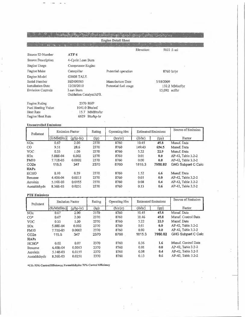
,AdteJupcMfa&i,riiWash]jpmpres™~~tF::cent~f:tank}Turforu
Source ID Number
Source Description
Engine Usage
Engine Make
Engine Model
Serial Number Installation Date Emission Controls
Engine Rating Fuel Heating Value Heat Rate Engine Heat Rate
Uncontrolled Emiss ions
ATF6
4-Cycle Lean Bum
Compressor Engine
Caterpillar
G3608 TALE
Potential operation
BEN00585 Manufacture Date 12/28/2010 Potential fuel usage Lean Burn Oxidation Catalyst/AFR
2370 BHP 1041.0 Btu/scf
15.7 MMBtu/hr 6629 Btu/hp-hr
Pollutant Emission Factor Rating Operating Hrs
NOx co voe SOx PMIO CO2e HAPs HCHO Benzene Acrolein Acetaldehyde
PTE E missions
Pollutant
NOx CO* voe SOx PMJ0 CO2e HAPs HCHO* Benzene Acrolein Acetaldehyde
(I b/MMB tu) I (g/hp-hr)
0.67 2.00 9.5 1 28.6 0.33 1.00
5.88E-04 0.002 7.71E-05 0.0002 115.5 347
0. 10 0.29 4.40E-04 0.00 13 5.14E-03 0.0155 8.36E-03 0.0251
Emission Factor
(lblMMBtu) I (g/hp-hr)
0.67 2.00 0.67 2.00 0.33 1.00
5.88E-04 0.002 7.71E-05 0.0002 115.5 347
0.02 0.07 4 .40E-04 0.0013 5.1 4E-03 0.0155 8.36E-03 0.025 1
(hp) (hrs/yr)
2370 8760 2370 8760 2370 8760 2370 8760 2370 8760 2370 8760
2370 8760 2370 8760 2370 8760 2370 8760
Rating Operating Hrs
(hp) (hrs/yr)
2370 8760 2370 8760 2370 8760 2370 8760 2370 8760 2370 8760
2370 8760 2370 8760 2370 8760 2370 8760
*CO: 93% Control Efficiency; Formaldehyde: 76% Control Efficiency
Elevation: 5022 ft as!
8760 hr/yr
5/18/2009 132.2 MMscf/yr
15,092 scf/hr
Estimated Emissions Source of Emission
(lb/hr) I (lpy) Factor
10.45 45.8 Manuf. Data 149.43 654.5 Manuf. Data 5.22 22.9 Manuf. Data 0.01 0.0 AP-42, Table 3.2-2 0.00 0.0 AP-42, Table 3.2-2
1815.3 7950.82 GHG Subpart C Cale
1.52 6.6 Manuf. Data 0.01 0.0 AP-42, Table 3.2-2 0.08 0.4 AP-42, Table 3.2-2 0.13 0.6 AP-42, Table 3.2-2
Estimated Emissions Source of Emission
(lb/hr) I (tpy) Factor
10.45 45.8 Manuf. Data 10.46 45.8 Manuf. Control Data 5.22 22.9 Manuf. Data 0.01 0.0 AP-42, Table 3.2-2 0.00 0.0 AP-42, Table 3.2-2
1815.3 7950.82 GHG Subpart C Cale
0.36 1.6 Manuf. Control Data 0.0 1 0.0 AP-42, Table 3.2-2 0.08 0.4 AP-42, Table 3.2-2
0.13 0.6 AP-42, Table 3.2-2

Source ID Number
Source Description
Engine Usage
Engine Make
Engine Model
Serial Number Installation Date Emission Controls
Engine Rating Fuel Heating Value Heat Rate Engine Heat Rate
Uncontrolled Emissions
SNWl
Sand Wash~Cg_mpressor-Stafipn.ffe
Engine Detail Sheet
4-Cycle Lean Burn
Compressor Engine
Caterpillar Potential operation
G3516TALE
4EK03 158 Manufacture Date 7/l7/2014 (replacement) Potential fuel usage Lean Burn Oxidation Catalyst/AFR
1340 BHP 1041.0 Btu/scf
9.92 MMBtu/hr 7401 Btu/hp-hr
Pollutant Emission Factor Rating Operating Hrs
NOx co voe SOx PMl0 C02e HAPs HeHO Benzene Acrolein Acetaldehyde
PTE Emissions
Pollutant
NOx CO* voe SOx PMIO C02e HAPS HeHO* Benzene Acrolein Acetaldehyde
(lb/MMBtu)I
0.60 6.46 0.10
5.88E-04 7.71E-05 115.5
0.09 4.40E-04 5. 14E-03 8.36E-03
(g/hp-hr)
2.00 21.7 0.33
0.002 0.0003
388
0.29 0.0015 0.0173 0.028 1
Emission Factor
(lb/MMBtu)I (g/hp-hr)
0.60 2.00 0.45 1.52 0.10 0.33
5.88£-04 0.002 7.71E-05 0.0003 115.5 388
0.02 0.07 4.40£-04 0.0015 5.14£-03 0.0173 8.36£-03 0.0281
(hp) (hrs/yr)
1340 8760 1340 8760 1340 8760 1340 8760 1340 8760 1340 8760
1340 8760 1340 8760 1340 8760 1340 8760
Rating Operating Hrs
(hp) (hrs/yr)
1340 8760 1340 8760 1340 8760 1340 8760 1340 8760 1340 8760
1340 8760 1340 8760 1340 8760 1340 8760
*CO: 93% Con trol Efficiency; Formaldehycle: 76% Control Efficiency
Elevation: ft asl
8760 hr/yr
6/15/2001 83 .5 MMsc:flyr
9527 sc:flhr
Estimated Emissions Source of Emission
(lb/hr) I (tpy)
5.91 25.9 64.11 280.8 0.97 4.3 0.01 0.0 0.00 0.0
1145.9 5018.93
0.86 3.8 0.00 0.0 0.05 0.2 0.08 0.4
Estimated Emissions
(lb/hr) I (tpy)
5.91 25.9 4.49 19.7 0.97 4.3 0.01 0.0 0.00 0.0
1145.9 5018.93
0.2 1 0.9 0.00 0.0 0.05 0.2 0.08 0.4
Factor
Manuf. Data Manuf. Data Manuf. Data AP-42, Table 3.2-2 AP-42, Table 3.2-2 GHG Subpart C Cale
Manuf. Data AP-42, Table 3.2-2 AP-42, Table 3.2-2 AP-42, Table 3.2-2
Source of Emission
Factor
Manuf. Data Manuf. Control Data Manuf. Data AP-42, Table 3.2-2 AP-42, Table 3.2-2 GHG Subpart C Cale
Manuf. Control Data AP-42, Table 3.2-2 AP-42, Table 3.2-2 AP-42, Table 3.2-2

Antelo11c Flats/ Strnd Wnsh Compresso1' Station & South Central Tank Battery Dehy Vent Delai l Sheet
DEll1' 1 Source Location Zone: 13 Elevation:
Source 1D Number Source Description Equipment Usage Equipment Make Equipment Model
70 MMSCFD TEG Dehydrator UTME:
Serial Number Dale in Service Emission Controls Equipment Configuration
Permit Status
GRI Glycalc Inputs
Annual Hrs of Operation Type of Glycol Used
Wet Gas Temperature Wet Gas Pressure Wet Gas Water Content Dry Gns FJow Rate Dry Gas Water Content Glycol Recirc. Pump Type Gas Pump Volume Ratio Flash Tank Present? Flash TMk Temperature Flash Tank Pressure "Flash Tank Control Stripping Gas Used Stripping Gas Flow Rate Condenser Present?
Glycol Dehydrator UTMN;
Dehy-1 2007 Low Emissions TEG Dehy TEG
TBD
8760 ( = 8760 hr/yr)
Potential operation
TEG (EG, TEG, DEG)
80 deg F 600 psig
Saturated lb H20/MMscf or Saturnted 70 MMscf7day
lb H20/MMscf (or# absorber stages) gal/II-water
Electric Electric/ Gas @ 1.5% H20 -- Default NI A acfm gas I gpm glycol y (YIN)
160 deg F 130 psig
Recycle Dry Gas (None, Dry Gas, Flash Gas, Nitrogen)
25 scfm y
Condenser Temperature 140 Condenser Pressure Alm
fl asl
8760 hr/yr
Gas Analyses from July 2008 (3rd Qtr)
Component
Helium Carbon Dioxide Hydrogen Sulfide Nitrogen Methane Ethane
Propane Isobulnno n-Butane Tsopentane n-Pentane
Cyclopentane n-Hexane Cydohexane Olher Hexanes Heptanes
Methylcyclohexane 2,2,4-Trimethylpentane Benzene Toluene Ethylbenz.ene
Xylenes C8+Hcavies
Total
Wet Gas (¾Vol.)
0.005 0.591
ND 0.167 91.57 4.425
1.626 0.335 0.432 0.180 0.151
0.009 0.073 0.043 0. 13 1 0.095
0.062 0
0.0 17 0.021 0.001
0.008 0.058
JOO

Antelope Flats/ Sand Wash Compressor Station & South Central Tank Battery Dchy Vent Deta il Sheet
DEHY 2 Source Location Zone: 13 Elevation:
Source ID Number Source Description Equipment Usage Equipmenl Make Equipment Model
I 00 MMSCFD TEG Dehydrator UTME:
Serial Number Date in Service Emission Controls Equipment Configuration
Permit Status
GRJ Glycalc Inputs
Annual Hrs of Operation
Type of Glycol Used
Wet Gas Temperature Wet Gas Pressure Wet Gas Water Content Dry Gas Flow Rnte Dry Gas Waler Content Glycol Recirc. Pump Type Gns Pump Volume Ratio Flash Tank Present? Flash Tank Temperature Flash Tank Pressure Flash Tank Control Stripping Gas Used Stripping Gas Plow Rate Condenser Present?
Glycol Dehydrator UTMN:
Dehy-2 8120/20 10 Low Emissions TEG Dehy TEG
TBD
8760 (<= 8760 hr/yr)
Potentinl operation
TEG (EG, TEG, DEG)
80 deg F 600 psig
Saturated lb H20/.MMscf or Satnrnted I 00 MMscflday
lb H20/MMscf(or H absorber stages) gal/#water
Electric Electric/ Gas @ 1.5% H20- Default NIA ncfm gas/ gpm glycol
y (YIN) 160 deg F 130 psig
Recycle Dry Gas (None, Dry Gas, Flash Gas, Nitrogen)
25 scfm y
Condenser Temperature 140 Condenser Pressure Alm
ft nsl
8760 hr/yr
Gas Analyses from July 2008 (3rd Qtr)
Component
Helium Carbon Dioxide Hydrogen Sulfide Nilrogcn Methane Ethane
Propane Jsobutane n-Butane Isopentane n-Pentane
Cyclopentane n-Hexane Cyclohexane Other Hexanes Heptancs
Methyleyclohexane 2,2,4-Trimcthylpcntanc Benzene Toluene Ethyl benzene
Xylenes CB+Heavies
Totnl
Wet Gas (¾Vol.)
0.005 0.591
ND 0.167 9 1.57 4.425
1.626 0.335 0.432 0.180 0.151
0.009 0.073 0.043 0. 131 0.095
0.062 0
0.017 0.021 0.001
0.008 0.058
100

Antelope Flats/ Sand Wash Compressor Station & South Central Tank Battery Heater Emission Calculation Sheet
}11-1,eat~rJ)ata
ID Description Nameplate Rating: Efficiency: Heat Input: Potential Fuel Usage Operation: Fuel Heat Value: voe Wt Fraction:
HTRI Heater I
5.00 (MMBtu/hr) 2- 2.5 MM Btu/hr Burners 0.80 (decimal) 6.25 (MMBtu/hr) 42 .1 MMScGyr
8760 (hr/yr) 1041.0 (Btu/set)
0.15 (decimal, VOC weight fraction of the fuel gas)
EIJliSsion Fri'ctcn1s'!, •;.-~ , .. :ff -- i,~ ••. 1·~
lb/MMscf Adjusted lb/MMscf* lb/MMBtu
NOx 100
102.l 0.100
co 84
76.0 0.D75
TOC II
11.2 0.01 I
CH20 0.D75
0.08 0.000
• Emission factor conversion based on footnote "a" of AP-42 Table 1.4-1 to convert from 1,020 Btu/scf to the above Fuel Heat Value in units ofBtu/scf.
tt1Eh1iSsfolfiGrilc1lla'tioJ1S -i:Jt':.~-4( ,~-~,,,nLlt ~t tj.~ _i;ttt\J:r1,rMJ: CJm,t <I< ·• •4:,!iAil~ 1 1"4f·¼.fH4:,k . Ji.,· , is·
NOx co b/hr (ton/yr) _{lb/hr ton/yr 0.63 2.7 0.47 2.0 0.00
_WCO?e E111i~sio]! Cafculatio~s ;,,ffiil',tn\~ffifu;if~;lf,;vwJc..xi.~'-'h~.;,1i,",dit1rti:Jirt-, ad:c:t
Conversions:
1 Metric Ton= 2204.62 lbs
1 kg= 0.001 metric tons
Pollutant kg/mmbtu metric ton tpy
co, 53.02 2,903 3,199.84
CH, 0.001 0 0.06
N2O 0.0001 0 0.01
CO,. = • ,lt, . •:tlff'J,203
CO,.= CO2 +(CH421) +(N,0'310)

Antelope Flats / Sand Wash Compressor Station & South Central Tank Battery Heater Emission Calculation Sheet Insignificant Source ifHea'!frD aia ""'"-l;t
ID Description Nameplate Rating: Efficiency: Heat Input: Potential Fuel Usage Operation: Fuel Heat Value: VOC Wt Fraction:
,, Emission Factors
lb/MMscf Adjusted lb/MMscf * lb/MMBtu
HTR 2 Heater 2
2.00 (MMBtu/hr) 0.80 (decimal) 2.50 (MMBtu/hr) 16.8 MMScf/yr
8760 (hr/yr) 1041.0 (Btu/sci)
0.15 (decimal, VOC weight fraction of the fuel gas)
p.0:~~,··ie--r.t
NOx co TOC CH20 JOO 84 JJ 0.075
102.1 76.0 11.2 0,08 0.100 0,075 0.01 I 0,000
* Emission factor conversion based on footnote "a" of AP-42 Table l .4-1 to convert from J,020 Btu/scfto the above Fuel Heat Value in units ofBtu/scf
rt.t -r- :~: 1:h!HT~, 1- 1:; ii;- " 4t
'i!Emissio.f! Cri lculalions" ,:f,t)u.,.,<li .;:111,··flii!i.,,1r'·~crlif····M,.,,_,:'i]21t'f.±..~,;!'1~1.~p·r~t:ifWt1it1L!ift!i'i'l!Efrrr!.i~t,,;i+·
NOx co voe lb/hr ton/yr lb/hr ton/yr lb/hr 0,25 1.10 0.19 0,82 0.00
l · COif~rt}ifsiorf Calc-ulatiorfs.L$ · :t-.J~~~~;Jt ~-!\.; '1i%;J\~l,J:h]t·~~~f',!t'.~--&~-r;I±fil~~
Conversions:
1Metric Ton= 2204.62 lbs
1kg= 0.001 melric lons
Pollutant kg/mmblu metric ton tpy
co, 53.02 1,161 1,279.93
CH, 0.001 0 0.02
N,O 0.0001 0 0.00
co,, = ,;'}';,W "1 ,;1.?81
CO,.= CO2 +(CH/21) +(N,0'310)
Ull' 11:." ,tfJtt1
r~:;

Antelope Flats/ Sand Wash Compressor Stat ion & South Central Tank Battery Hcatc.r Emission Calculation Sheet lnsie;nificant Source
Heater))a ta <:• '
ID Description Nameplate Rating: Efficiency: Heat Input: Potential Fuel Usage Operation: Fuel Heal Value: VOC Wt Fraction:
;,E'n1iSslbn Fri'ct<frs
lb/MMscf Adjusted lb/MMscf• lb/MMBtu
HTR3 Heater 3
1.20 (MMBlu/hr) 0.80 (decimal) 1.50 (MMBtu/hr) JO. I MMScf/yr
8760 (hr/yr) l 04 J.0 (Blu/sc()
0.15 (decimal, VOC weight fraction of the fuel gas)
NOx co TOC CH20 JOO 84 11 0.075
102.1 76.0 11.2 0.08 0.100 0.075 0.011 0.000
• Emission factor conversion based on footnote "a" of AP-42 Table 1.4-1 to convert from 1,020 Btu/scf lo the above Fuel Heat Value in units ofBlu/scf.
'ijEmisslori Calculations !·}li,,,p'{ :,j{ -,4,J -;:r,
NOx co lb/hr {ton/yr lb/hr ton/yr 0. 15 0.66 0.11 0.49
tr_CoieEmfssionJCalculations . ,., ::,,_,.r,,,,·,ili''.~.:.tl ~t":f 'l!U ~4 ,lillJT 'j;::,:hf0 frJJtr-"llti
Conversions:
1 Melriclon = 2204.62 lbs
1 kg= 0.001 metric tons
Pollutant kg/mmbtu metric ton tpy
co, 53.02 697 767.96
CH, 0.001 0 0.01
N,O 0.0001 0 0.00
CO2. = ~, g)l¥, P 69
CO,,= CO,+ (CH,"21) + (N2O"310)
v~ . .ttr-

'-'....C -· ....;..;..;. .... ~.:....;...;...;;.·.....;....• . .......__'"'-, .....;..;..· • ...:.... ..;...;..· • ....;..:;..: -· ·-·-· •• ...;.i;... •. ... .....,_..._ ....... _..,.._._ ......... __ !_ .. ,,._.; ... -,~-----... ---.-
~ Names Un1ts Flash
caroon DJoxide(Mass Fbw) ton/yr 1.9 Methane(Mass Flow) ton/yr 13 Benzene/f~ass Flow> tontvr 0.4 Tol tumea~ass flow} tonfvr 0.3 E.thy]l)enzene(ltass Flow} ton/yr 0.012 p.-Xylene(Mas:s Flow) ton/yr 0 .054 n-Hexane(Mass Flow} ton/yr 3 .3
Annual tank .fess calculations foc '!Mixed Liquids Inlet". Flashing losses are 27.541on/'yr.
" Only NonsExempl voe are reported.
Tank- ,,..::--1,;. I~
• --Mixed Liquids lnlel II K,a
-.i~:;--·,-;\:. ~.
. , .... ·;-;,. ~- ........ ~- r H:,·;;. C~ .~,'. r; : •
Mixed Liquids to Truck~ ''1! • ~
Na:res tJr.JS Ml>l!dua;i:ISrn!!l Aasn MIXeduo.cn;D>TftllX oCa:Jm:'ITI"ff'rJPJ"il.~P-r.:arTT'11 $ a.om 2.7 (l.0015 Annua11ank foss calcuf.ilions for "Mixed Liquids Inlet".
- "'1eRa<flXI) ~- 7.7e--05 l ~ !l,!Ol! F..,_.rrn % a.;2 t-rn;r-pf&.«))e '?i, Q.025
0.036 5i 11
6e-01 a.oou Q.0021
Total working and breathing losses from the Vertical Cytinder are 0.0 11591 toll/yr. loading losses are 0.02575 ton/yr ofloaded. tiquTd.
~!).'10.leF"r.cbll % = 10 CLCm4 * Only Non-Exempt voe are reported. t--Eaa>er>M>11! Fnctlco) .. 0.013 3'.5 . 0.0058 o-l3ctilce~t-r.ltTWTII ~- Cl.0'5 S.7 0.01• Tank 1--Pectale(W.ole Frac:aa» % Cl.Cl2l 2..8 Q.018 -~ ~- 0.026 2.5 0.022 H-,.<ole~ % a., OS OC1
D-Oc:tz-e-""""""' ~- Q.083 0.21 0.083 l\'CX1anel'),':011! Frad:Xal % 0.013 Cl.0(m Q.013 c-,o +(Mell! Fraco::cf!. ~-..-ato1eF~1 % 0.014 0.33 Q.013
TObene !9 Q.028 0.21 0;028
% = 0.007'5 Q.tm3
~ir-a.4.0Je Fsac::tl:n) '% Q.014 Q.033 0.014 % 0.08!1 2.4 a..033
u::;a,v,,u,ll!lltcF!lc>o ttn>:l 2B7.85 T.n15 215.95
.;....,.~ ;.......-_._ ..
.1--,.
:-

Pigging Emissions Estimates
Pigging Days =
Estimated voe Rate =
voe Emissions=
365 days
0.1 O lb/hr
0.44 ton/yr

Antelope Flats / Sand Wash Compressor Station & South Central Tank Battery Flare Detail Sheet
Source ID Number Source Description Equipment Usage Equipment Make Equipment Model Serial Number Date in Service Equipment Configuration
Pilot Fuel Heating Value Fuel Heat Rating
Potential Emissions
Pollutant
NOx co
Emission Factor
(lb/MM Btu) 0.068 0.37
Flare Flare
1041 Btu/scf 4.0 Mmbtu/hr
Source Location Zone:
Potential operation
Potential fuel usage
UTME: UTMN:
8760 hr/yr
1 .40 MMscf/yr 160.1 scf/hr
Hrs of Operation
(hrs/yr) Estimated Emissions Source of Emission
8760 8760
(lb/hr) 0.27 1.48
(tpy) (lb/yr) Factors 1.19 2382. 7 AP-42 Table 13.5-1 6.48 12964.8 AP-42 Table 13.5-1
·~ 9.?i ~mfs! i<>itcajcu!<!tio'ris: ...... :,::r1, !i?:,1:1iwlthte··""IJ, t?;;~i ~;f"J·11~;]r\t;l¾U'~
Conversions:
1 Metric Ton= 2204.62 lbs
1 kg= 0.001 metric tons
Pollutant kg/mmbtu metric ton tpy
CO2 53.02 1,858 2,048
CH4 0.001 0 0
N20 0.0001 0 0
CO2.= .~:~ ),OpO
CO2.= CO2 +(CH/21) +(N20*310)
GHG emission factors from '40 CFR 98 Table C-1 , C-2.

Antelope Flats/ Sand Wash Compressor Station & South Central Tank Battery
L-1 Source ID Number
Source Description
Source Usage
Potential operation
Condensate Loadout @ South Central Tank Battery
Condensate Loadout
Potential Emissions
voe HAP
Gas Analysis
Estimated Fugitive Emissions - Potential
API Gravity at Sales Temp
Reid Vapor Pressure
True Vapor Pressure, Pva @ T
Molecular Weight of Vapors, MW
Average Sales Temperature, T
Saturation Factor
Efficiency of controlled loading(%)
Annual throughput, v
Loading losses, L @ tank
8760 hr/yr
18.28 tpy
0.88 tpy
L = 12.46 SP MW/ T (1-eft)
Annual losses @ tank, L *v
Hazardous Air Pollutant Speciation
Potential Operation
See calculation below
Percent ofVOC from liquid analysis
(see AP-42 Section 4.4)
66
8.306
4.8 psia
68.00 lb/lb-mol
51.98 F 511.65 R
0.6
0.0%
7,665 .0 1000 gallons
4.77 lb/1000 gallons
36,556 lb/yr
From Liquid Analysis
From Liquid Analysis
Figure 7.l-13a of AP-42
From Gas Analysis
Dedicated service
18.28 tpy
Component Mole% AP Emissions (tp Source of Emissions
Benzene
Toluene Ethylbenzene Xylenes n-Hexane 2,2,3-Trimethylpentane
TOTAL
0.4684%
0.4379% 0.0118% 0.0971% 3.6810% 0.1269%
0.086 Speciated based on percent in TK-0.080 1601 vapor emissions
0.002 0.018-0.673 0.023
0.882

C~mponent Source Counts fo r Gas P la nt/Comp_r_<,5sor Station Units
Mole Sieve Equipment Type Compressor Separator Condensate Tanlc TEGUnit DEA Unit C3 Refrig Skid Expan Demeth System Flare
For this facility, Number of Units r.i.,,,V<f~ '7~tJii!'• '~:'~i~Jti;.~:i,:,;,~L~~'tg-fi ~~:r.,.·.r;..:,J-f,/ , ....... _~~~.~~.-·wt~&.~,~· ~ :"j1:~~,~ ~i, --: ~ 4-f~!:;~;_ 0 -·..:,_?~~~p:f,~:/ ·\Ji ::~ Valves - Inlet Gas 40 6 4 75 15 40 40 25 8 Valves - Liauid 5 4 6 20 60 35 35 0 2 Relief Valves 2 2 2 4 4 6 6 4 2 P umn Seals - Liauid 0 0 2 4 4 0 0 0 0 Flanges/Connectors - Inlet Gas 150 50 50 250 250 250 250 100 75 Flan<!es/Connectors - Liauid 10 JO JO 20 20 20 20 20 IO Comoressor Seals 4 0 0 0 0 6 0 0 0
Fugitives ., Em1ss1on Factor vuc 1'miss1on HAP .i,m1ss1on HAP .Emission voe Emission
Equipment Type (lb/hr/ source) Source Count • %VOC CJ + %HAP Rate (lb/hr) Rate (lb/hr) Rate (tpy) Rate (tpy) Valves - Inlet Gas 0.00992 570 11.40% 0.12% 0.645 0.007 0.030 2.82 Valves - Liquid 0.00550 215 100.00% 11.40% 1.183 0.135 0.590 5.18 Relief Valves 0.01940 78 11.40% 0. 12% 0.173 0.002 0.008 0.76 Pump Seals - Liquid 0.02866 38 100.00% 11.40% 1.089 0.124 0.544 4.77 Flanges/Connectors - Inlet Gas 0.00086 2975 11.40% 0.12% 0.292 0.003 0.013 1.28 Flanges/Connectors - Liquid 0.00024 390 100.00% I 1.40% 0.094 0.0 11 0.047 0.4 1 Compressor Seals 0.01940 28 11.40% 0. 12% 0.062 0.001 0.003 0.27
Total 3.536 0.282 1.23 15.49
• Source counts estimated from similar: facilities. These counts are not actuals. Source: EPA Protocol for Equipment Leak Emission Estimates, November, 1995, EP A-453/R-95-017

Appendix G
Ambient Air Quality Analysis

Air Quality Impact Qualitative Analysis
There are two ambient air quality monitors within the Basin that monitor ozone and nitrogen dioxide (NO2). Results of the two monitors (Site ID 49-047-2002 - near Redwash and Site ID 49-047-2003 -
near Ouray) are summarized below:
SITE ID# YEAR POLLUTANT 1st MAX 2nd MAX 3rd MAX 4th MAX 49-047- 2009 NO2- l-hr 19 16 2002
2010 NO2- I-hr 55 41 2009 03 -1-hr 63 62 61 60 2010 03 - I-hr 120 114 111 108 2009 03 - 8-hr 60 58 58 56 2010 03 - 8-hr 105 103 99 88
49-047- 2009 NO2- 1-hr 12 10 2003
2010 NO2- 1-hr 56 40 2009 03 - 1-hr 66 66 62 62 2010 03 - 1-hr 139 131 131 130 2009 03 - 8-hr 61 60 57 57 2010 03 - 8-hr 123 122 122 117
*concentrations are in ppb
The monitoring data suggests that the area is of lesser concern for NO2 emissions since the highest recorded concentration in the two monitoring years was just slightly above 50% of the standard. While
the table does not show the annual NO2 monitoring values, they are well below the standard. This facility has been operating since 1996, and therefore the associated emissions should already be represented in the
existing monitoring data.
The monitoring data does show elevated ozone concentrations in 2010. While there is concern with the winter time ozone issues, the area is listed as unclassifiable. Again, this facility has been operating since
1996, and therefore the associated emissions should already be represented in the existing monitoring
data.
Environmental Impact Statement: In March of2012 the Final Environmental Impact Statement (FEIS) for the Greater Natural Buttes area was completed and modeling was done as part of the EIS. While this is not a regulatory modeling exercise, it does give an indication of the air quality in the area. NO2, SO2 and summertime 03 were modeled. Attached is the air quality excerpt out the FEIS. The modeling indicates compliance with al l NAAQS and increment standards. The modeled concentrations indicate compliance with the ozone standard during the summer months

4.0 Environmental Impacts
This chapter presents discussions of the environmental impacts associated with the Proposed Action and the alternatives presented in Chapter 2.0. Disturbance comparisons for these alternatives are presented in ·rable 2.10-1 , thus providing the reviewers and the decision maker a side-by-side comparison of the potential alternatives tor each key resource topic. Analysis of environmental impacts in this chapter is confined to that associated with new disturbances for each alternative. To estimate the total impacts for each action alternative, the impacts for the No Action Alternative must be added to the Impacts for each alternative. Many of the effects identified as a result of oil and gas development occurring under the No Action Alternative also would occur under expanded oil and gas activities associated with implementation of the Proposed Action or other action alternatives. Differences among the action alternatives generally would be in the degree or level of effects. Expansion of the existing oil and gas field would create effects that overlap or combine with those occurring under the No Action Alternative. These effects are analyzed in detail in Chapter 5.0, Cumulative Effects.
It should be noted that final well siting and associated site-specific effects would be determined in detail during the APD phase of the permitting process. Under this process. each well would undergo additional biological, cultural , and p!'lleontological evaluation prior to construction, as directed by the BLM (Section 2..3, Management Common to All Alternatives). Additional site-specific mitigation requirements also may be added at that time. The environmental impacts identified in this EIS are based on general well locations as discussed in Chapter 2.0 of this document.
Planned natural gas developments in the GNBPA under the No Action Alternative are described in previously approved NEF'A documents identified in Section 2.4.1. As of October 2007, there were 1,102 undrilled wells within the GNBPA that have been described in approved NEPA decision documents or identified in the UDOGM database. As of October 2007, UDOGM data indicated that 584 federal wells, 192 State of Utah wells, 9 wells on Indian lands, and 9 wells on private lands had approved APDs or were actively drilling Within the GNBPA.
f EIS 4-1 March 201 2

4.1 Air Quality
The purpose of the air quality analysis was to assess local and regional air quality impacts from current and future reasonably foreseeable development in the Uinta Basin Region, in conjunction with the proposed project. The general approach was to develop an emissions inventory for a "project base year'' (defined below) to tabulate emissions and conduct modeling.
The alr quality analysis incorporated the planned development and a prepared set of emissions data for project modeling, including project development alternatives and reasonably foreseeable development as discussed below. Those emissions data were incorporated into the modeling system for the project base year, and used to predict potential impacts on visibility, acid deposition, and air quality, including ozone. The analysis identifies potential impacts on resources evaluated, and characterlzes the major source or source groups that contribute to those impacts.
The 2006 emissions data was used as the basis for comparing emissions and impacts for the base year. This selection was made to coincide with the 2006 Western Regional Air Partnership (WRAP) Phase Ill emissions inventory for the Uinta and Piceance basins, which was developed by a collection of government and industry stakeholders for ozone modeling in the same area. As such, these data serve as the best available data for base year emissions and comparisons.
Emissions of criteria pollutants and source characteristics for the proposed project alternatives were based on project data provided by KMG. To support the modeling effort, emissions scenarios were developed for the base year and 3 forecast years and included reasonably foreseeable development, the proposed project, and maximum production. Emissions inventories were developed for each of the following scenarios:
• 2006 Baseline - 2006 base year actual emissions;
• 2018 Projected Baseline - 2018 projected emissions without the proposed project;
• 2017 Proposed Action Alternative - 2018 Projected Baseline emissions with project emissions from the proposed alternative in 2017; and
• 2026 Optimal Recovery Alternative - 2018 Projected Baseline emissions with project emissions from the maximum recovery development alternative in 2026.
The 2018 Projected Baseline essentially is the No Action Alternative1 but also includes non-project emissions. The Resource Protection Alternative focuses on minimizing land disturbance for the installation and operation of wells and other support facilities. From an air emissions perspective, ambient impacts from the Resource Protection Alternative are well-characterized by the impacts from the Proposed Action. For that reason. the Resource Protection Alternative was not modeled as a separate evaluation.
The 2018 Projected Baseline was used as the baseline for the Optimal Recovery Atternative, though peak production under this alternative is anticipated in 2026. This approach provides a consistent basis of comparison between the alternatives and reduces uncertainty in baseline emissions from projecting development beyond the WRAP inventory time horizon.
The 2018 Projected Baseline does not include estimates of emissions from existing evaporation ponds in the GNBPA. However, the emissions from these ponds are consetvatively estimated to be 45 ,tpy voe and 39 tpy HAP. The estimated voe levels for the evaporation ponds are fess than 0.1 percent of the voe emissions for the projected baseline emissions used in ozone modeling (see Appendix G).
GHGs are produced ahd emitted by various sources during phases of oil and gas exploration, well development, ancl production. The primary sources ofGHGs associated with oil and gas exploration and production are CO2, N20, and CH4, In addition, volatile organic compounds (VOCs) are a typical source of
liGII- 4-2. March 2012

emissions associated with oil and gas exploration and production. Under specific environmental conditions, N20 and VOCs form ozone, which also is considered a GHG.
Climate change analyses are comprised of several factors including, but not limlte<'.I to, GHGs, land use management practices, and the albedo effect. While emissions from oil and gas activities may contribute to the effects of climate change to some extent, it currently is not possible to associate any of these particular actions with the creation of any specific climate-related environmental effects. The tools necessary to quantify climatic impacts presently are unavailable. As a consequence, impact assessment of specific effects of anthropogenic activities cannot be determined. Additionally, specific levels of significance have not yet been established. Therefore, climate change analysis for the purpose of this document focuses on accounting and disclosing of GHG emissions that may contribute to climate change (see Section 3.1.3. 7 for text acknowledging related potential impacts).
Emissions Data Development
Emissions data for the Proposed Action and the Optimal Recovery Alternative were developed from available emission factors, analytical data, applicable ACEPMs (Appendix A), applicant-provided equipment specifications, and anticipated activity levels. Emission rates were developed for the criteria pollutants and for selected HAPs. A summary of criteria pollutant emissions from stationary sources in the Uinta Basin is provided in Table 4.1-1 , and the project-related increases in the major components of HAPs for the Proposed Action and Optimal Recovery Alternative are provided in Table 4.1-2. Emissions for a full list of HAPs were reviewed, but only those with the greatest emissions in relation to health effects were evaluated. A summary of emission calculation methods for each source type and pollutant is shown In Table 4.1-3.
Table 4.1-1 Summary of Criteria Pollutant Emissions for Each Scenario
Emissions (tpy)
2026 Optimal Recovery
Criteria 2006 2018 Projected 2017 Proposed Action Alternative
Pollutant Baseline Baseline Project Total Project Total
NOx 10,754 10,138 2,213 12,351 4,946 15,084 co 7,800 9,732 1,300 11,032 2,994 12,726 S02 391 30 25 55 78 108 PM10 592 565 1,011 1,576 2,658 3,223
voe 70,226 184,262 6,617 190,879 24,976 209,238
Source: Alr Quality Technical Support Document (Appendix G).
Table 4.1-2 Summary of Potential Increases in Emissions of HAPs for Project-related Alternatives
Potential HAP Increase (tpy)
Pollutant Proposed Action Alternative Optimal Recovery Alternative
Benzene 67.0 255.2 Toluene 172.4 662.1 Ethyl Benzene 12.7 48.5 Xylenes 185.7 714.1 Formaldehyde 71.3 156.5 n-Hexane 194.9 748.5
Source: Alr Quality Technical Support Document (Appendix G).
FEJS 4-3 Mamh2012

Table 4.1-3 Summary of Emissions Calculation Methods by Source Type and Pollutant
Source Type Pollutant Emissions Calcµlatlon Methodology Drill Rig Engines NOx 40 CFR '1039, 101
co Tier 2 - Near-field Impact Analysis voe Tier 4 - Near-field Impact Analysis and Regional Emissions
PM/PM1c/PM2.s SO2 Mass balance of fuel sulfur ( 15 ppm weight [ppmw] fuel sulfur) HAP National Mobile Inventory Model Database (USEPA 2005)
I Drill Rig Boilers All USEPA AP--42 Volume I: Stationary Sources Chapter 1.3 (USEPA 1998b) Drilling and Completion NOx USEPA AP-42 Volume II : Mobile Sources (USEPA 1995a) Traffic co
voe PM,o/PM2.6 USEPA AP-42 Volume l Chapter 13.2,2 (USEPA 2006) and USEPA AP-42
Volume II: Mobile Sources (USEPA 1995a) SO2 USEPA AP-42 Volume II : Mobile Sources (USEPA 1995a)
I Condensate Flashing voe American Petroleum Institute (AP/) E&P Tanks v2.0 based on Analysis of HAP Condensate
I Separator Heaters NOx USEPA AP-42 Volume I: Stationary Sources Chapter 1.4 (USEPA 1998c)
I
co voe PM/PM 10/PM2.s SO2 Mass balance of fuel sulfur [20 ppmw fuel sulfur] HAP USEPA AP-42 Volume I: Stationary Sources Chapter 1.4 (USEPA 1998c)
Production Well voe USEPA Protocol for EQuipment Leak Estimates (USEPA 1995b) Fugitives HAP Mass fraction ofVOC based on Analvsis of Condensate Production Traffic NOx USEPAAP-42 Volume II: Mobile Sources (USEPA 1995a)
co voe PM1o/PM2.s US EPA AP-42 Volume I Chapter 13,2.2 (US EPA 2006) and
USEPA AP-42 Volume II : Mobile Sources (USEPA 1995a) SO2 USEPA AP-42 Volume II : Mobile Sources (USEPA 1995a)
Produced Water Tank voe TANKS 4.09 based on Analysis of Condensate Batteries HAP Mass Fraction ofVOC based on Analysis of Condensate Gas-fired Compression NOx Engine Manufacturer Specifications Engines co
voe PM,o/PM2s USEPA AP-42 Volume I: Statlonarv Sources Chapter 3.2 (USEPA 2000)
SO2 Mass balance of fuel sulfur 120 ppmw fuel sulfur] HAP USE PA AP-42 Volume I: Stationary Sources Chapter 3.2 (USEPA 2000)
Source: Alr Quality Technical Support Document (Appendix G).
The air quality model AERMOD was usecj to evaluate impacts on air quality in the near0 field . Several scenarios, Including various well spacing and drill density plans, were evaluated to determine their projected impacts on the near-field. A square mile area was used to characterize the scenario sources arrangement, and impacts were calculated within that area and at the boundary of the square mile area. For drilling operations, it was assumed that up to four drill rigs would operate in this area at any one time. Annual impacts from drilling operations were based on the assumption that 64 wells could be drilled in a square mile to accommodate the proposed 10-ac:re downhole spacing. For operations, the source arrangement depicted wells located on a 10-, 20-, and 40-acre spacing. For compression, a single compressor station was sited in the area and impacts were calculated in the near-field.
FEJS 4-4 Maleh 2012

The CALPUFF modeling system was used to estimate impacts on visibility (regional haze), air quality, ahd acid deposition in areas 50 kilometers (l<m) or more from the development area. The Models-3 Community Multiscale Air Quality (CMAQ) model was used to evaluate impacts on ambient air ozone in the region.
An inventory of actual emissions developed specifically for this analysis were input to the AERMOD and CALPUFF models to analyze compliance with the NAAQS and evaluate impacts to regional haze, acid deposition, and acid neutralizing capacity at sensitive lakes in Class I areas. Comparison of impacts to PSD increments is provided for informational purposes only; this study does not represent a PSD increment-consumption analysis. Th~ inventory for the CMAQ ozone modeling utilized actual project base year emissions along with emissions from other sources (i.e., electric generation, motor vehicles, and biogenics).
The CAA lists HAPs that could be emitted during project operations: primarily BTEX (benzene, toluene, ethyl benzene, and xylene) from the well dehydrators and formaldehyde from the pipeline compressor engines. Control of these and other HAPs would be achieved through compliance with applicable MACT standards. HAP emissions for each activity were developed on a per unit basis and were based on approved emissions factors, mass balance, or process simulation, where appropriate. Site-specific supporting information such as operation schedules, equipment specification, and physical and chemical properties of fuel and materials were used to develop the emissions inventory for the various alternatives. Where site-specific information was not available, the analysis used published references or assumptions based on professional experience as d,escribed in the Technical Support Document (Appendix G).
NESHAP and MACT regulations for oil and hatural gas production facilities include provisions for ethylene glycol dehydrators and vents, storage vessels with flash emissions, and ancillary equipment. Under these provisions, any source that emits or has the potential to emit 10 tpy or more of any HAP is considered a major source; would require an operating permit under Title V of the CAA; and must install and operate control equipment to control air emissions. Under these same provisions, glycol dehydration units emitting less than 1 tpy benzene are considered "small," and would not require controls under MACT rules.
Ambient air concentrations of HAPs were determined based on these emissions rates using the same AERMOD model scenarios used for near-field criteria pollutant analysis. These ambient concentrations were compared to the USEPA Toxic Screening Levels (TSLs) to determine if any adverse Impact would be predicted from project-related source emissions.
Based on the minimal content of hydrogen sulfide (H2S) in the natural gas found in the GNBPA, potential H2S impacts would be negligible. However, should H2S be encountered, operations on federal or Indian leases would be regulated by Onshore Oil and Gas Order No. 6 (Hydrogen Sulfide Operations}. This order requires monitoring of H2S beginning at levels of 10 ppm at each drilling well (40 CFR part 63, subpart HH §63.760[b][1] through [4] ; and 40 CFR part 63, subpart A of the General Prov1sions, effective June 17. 1999). Should H2S levels increase, specific drilling and production equipment, along with drilling and public protection plans, would be required under Onshore Order No. 6 in zones where H2S can reasonably be expected to be present at concentrations of 100 ppm or more .
The analysis was based on several conservative assumptions, including:
•
•
•
FEIS
Maximum measured and/or estimated background criteria air pollutant concentrations were assumed to occur at all locations in the region throughout the life of the project.
All existing emissions sources were assumed to operate at their reasonably foreseeable emission rates simultaneously throughout the life of the project. Given the number of sources included in this analysis, the probability of such a scenario actually occurring over an entire year (or even 24 hours} is small. While this assumption is typically used in modeling analyses, the resulting predicted impacts would be overstated.
For the near-field modeling, total predicted short-term air pollutaht impact concentratiohs were assumed to be the .sum of the first maximum background concentration, plus the maximum modeled
4-5 March 2011

concehtratiohs, which actually would occur under very different meteorological conditions and would not be likely to coincide.
• The HAP analyses assumed all existing equipment would continue to operate simultaneously at the assumed emission levels continuously throughout the life of the project. Since no data are available to characterize HAP concentrations in the vicinity of the GNBPA, no background HAP concentrations were assumed for near-field modeling.
4.1.1 No Action Alternative
On SLM-administered lands, current management plans would continue to guide oil and natural gas exploration and development activity, Air quality effects for the No Action Alternative would include an increase in air pollutant emissions resulting from drill and development projects previously approved.
Emissions for the No Action Alternative are represented by the 2018 Projected Baseline, specifically including the WRAP Ill data for the Uinta and Piceance basins, and the WRAP II data for other basins.
4.1.1.1 Impacts on Air Quality
The USEPA dispersion model AERMOD was used to predict maximum potential near-field air quality impacts from existing emission sources, which would continue to operate under the No Action Alternative. As of October 2007. there were 1,102 undrilled wells within the GNBPA that have been described in approved NEPA decision documents or identified in the UDOGM database. The analysis results identify predicted air pollutant concehtrations in the vicinity of producing wells (drlll rigs}, compressor engines, and related oil and gas facilities. Specific modeling scenarios for the near-field impact analysis are discussed In more detail in Appendix G.
CALPUFF modeling was used to predict impacts at distant receptors (greater than 50 km from the GNBPA), mandatory federal PSD Class I areas for comparison with applicable air quality standards, PSD increments. HAP exposures, visibility standards, and atmospheric deposition (Appendix G).
Because this altemative includes wells that have not yet been drilled, there would be construction-related air quality impacts. Construction emissions would occur during road and well pad construction, well drilling, and well completion testing. In addition, particulate matter (PM2.s and PM10) concentrations likely would increase during construction. Potential S02 emissions would be generated by drilling rigs and other diesel engines used during rig-up, drilling, and completion operations (sulfur being a trace element In diesel fuel) . Maximum air pollutant emissions from each well would be temporary (i.e., occurring only during the construction period), would occur in isolation, and would not significantly interact with adjacent well locations. Since construction emissions would be temporary, PSD increments are not applicable.
Near-field modeling was conducted to determine the impacts from simultaneous operation of drill rigs on adjacent pads spaced at 400-meter inteNals. This modeling assumed drill rigs (each with two drill rig engines and one rig boiler) operating simultaneotJsly on each of four adjacent pads. Both Tier 2 ~nd Tier 4 drill rig engines were modeled, with the data shown separately In Table 4.1-4. Modeling for the single completion rig engine on four adjacent pads was conducted separately and showed lower impacts than the scenario with four drill rigs.
The maximum impacts of criteria pollutants in the near-field for this alternative are presented in Table 4.1•4. As shown in Table 4.1-41 the near-field modeled impacts would be in compliance with the NAAQS.
FEJS 4-6 March 2012

Table 4.1-4 Air Quality Impacts for Criteria Air Pollutants in the Near-field, No Action Alternative
Modeled Impact' Background Pollutant Standard (µg/m3) Concentration (µg/rn3
) Total Impact (µg/rn3)
NO2 1-hou? 137.1 NIA3 157.2
(106.9) (125.6)
Annual4 7.7 9.0 16.7
(2.0) (11 .0)
co 1-hour 399 6,325 6,724
8-hour 251 3,910 4,161
SO2 1-houl 2.6 21.7 24.3
3-hour 1.9 16.7 18.6
24-hour 0.9 5.9 6.8
Annual 0.1 1.5 1.6
PM10 24-hour 4.5 18 22.5 (0.7) (18.7)
PM2.5 24-hour 4.5 21.6 26.1 (0.7) (22.3)
Annual 0.0 12.3 12.3 (0.0) (12.3)
1 Modeled results are bued on Tier 2 engine emlsslor, factors; results In parentheses reOect ner 4 engine emission factors. 1 Modeled Impacts ilre the 5-year aver11ge 9ti" percentile daily maximum. 1 1-hour NO, mode/Ing used background concentrations that vary by seasor, and hour of day.
NAAQSI SAAQS (µg/m3)
188
100
40,000
10,000
196
1,300
365
80
150
35
15
'For annual averaging period, predicted concentration does r,ot Include II reduction from NO" to NO,. All N"1( /!I presumed to be NO,.
• Modeled impacts are the 5-year average 9glh percentile dally maximum.
Sovrce: Air Quality Technical Support Document (Appendix G; Tables 5-111 5-12, and 5-13).
Comparison of modeled HAP concentrations against USEPA TSLs and Reference Concentrations (RfC) indicates no adverse impacts from emissions of HAPs from project sources. The maximum concentrations are predicted from the 10-acre production scenario (64 operating wells per section) for all pollutants. These results are shown in Table 4.1-5.
Table 4.1-5 Air Quality Impacts for HAPs in the Near-field, No Action Alternative
Concentration per Production Well Density (µglm3) Non-Carcinogenic
Pollutant/Averaging 10-Acre 20-Acre 40-Acre RfC1 TSL2 Period Spacing Spacing Spacing (µg/m3) (µglm3)
Benzene
24-hour 5.25 4.14 2.99 - 53.3
Annual 1.55 1.22 0.71 30 -Ethylbenzene
24-hour 0.32 0.26 0.18 - 14,473
Annual 0.17 0.13 0.08 1,000 -
FEIS 4-7 March 2012

Appendix H
Regulatory Analysis

Regulatory Analysis
Applicable and potentially applicable Federal regulations for the Antelope Flats / Sand Wash Compressor Station / South Central Tank Battery (the Facility) are discussed below:
40 CFR 52 - Prevention of Significant Deterioration (PSD) Subpart A, General Provisions describe general requirements for pre-construction review and permitting for major sources under the PSD program. Based on the potential to emit of the Facility, the Antelope Flats / Sand Wash Compressor Station is a not PSD major source and the regulations are therefore not applicable.
40 CFR 60 - New Source Performance Standards (NSPS)
Subpart A contains general requirements for notification, testing and reporting for the NSPS program. The subpart applies to each facility that has an affected source as defined under another subpart. There are affected sources at the Facility under Part 60, Subpart A does apply.
Subpart Db, Standards of Performance for Small Industrial, Commercial, Institutional Steam Generating Units, applies to steam generating units having a capacity greater than 100 MMBtu/hr that are construction, reconstructed or modified after June 9, 1989. No heater located at the facility is rated greater than 100 MMBTU/hr, therefore, NSPS Subpart Db is not applicable.
Subpart De, Standards of Performance for Small Industrial, Commercial, Institutional Steam Generating Units, applies to steam generating units having a capacity between 10 MMBtu/hr and 100 MMBtu/hr that are construction, reconstructed or modified after June 9, 1989. A steam generating unit is defined, by rule, as follows:
"Steam generating unit means a device that combusts any fuel and produces steam or heats water or any other heat transfer medium. This term includes any duct burner that combusts fuel and is part of a combined cycle system. This term does not include process heaters as de.fined in this subpart. "
No heater located at the facility is rated at greater than 10 MMBTU/hr, therefore, NSPS Subpart De is not applicable.
Subpart K,_Standards of Performance for Storage Vessels for Petroleum Liquids for Construction, Reconstruction, or Modification Commenced after June 11 , 1973, and Prior to May 19, 1978. The storage vessels at the faci lity were constructed after May 19, 1978; therefore, NSPS Subpart K is not an applicable regulation for the Facility.
Subpart Ka, Standards of Performance for Storage Vessels for Petroleum Liquids for Construction, Reconstruction, or Modification Commenced after May 1, 1978, and Prior to July 23, 1984. The storage vessels at the Faci lity were constructed after July 23 , 1984; therefore, NSPS Subpart Ka is not an applicable regulation for the Facility.
Subpart Kb, Standards of Performance for VOL Storage Vessels, regulating volatile organic liquid storage vessels having a storage capacity greater than 75 m3 (19,815 gallons), constructed after July 23, 1984. VOL storage vessels at the Facility have a capacity less than 75 m3 but records of tanks size have to be kept, therefore this subpart is applicable.
Subpart GG, Standards of Performance for Turbines -applies to all stationary gas turbines with a heat input at peak load equal to or greater than 10. 7 gigajou les (10 million Btu) per hour, based on the lower

heating value of the fuel fired and constructed, modified, or reconstructed after October 3, 1977. There are no gas turbines at the Facility therefore this subpart is not applicable.
Subpart KKK, Standards of Performance for Equipment Leaks of VOC from Onshore Natural Gas Processing Plants, applies to affected facilities in onshore natural gas processing plants. The Facility is not a natural gas processing facility, as defined in §60.631; therefore, this subpart is not applicable.
Subpart LLL, Standards of Performance for Onshore Natural Gas Processing: SO2 emissions, applies to facilities that process natural gas and have sweetening units. The Facility is not a natural gas processing facility and does not have a sweeten ing unit; therefore, NSPS Subpart LLL is not an applicable regulation at the current time.
Subpart VV, Standards of Performance for Equipment Leaks of VOC in the Synthetic Organic Chemicals Manufacturing Industry, this subpart applies to affected facilities in the synthetic organic chemicals manufacturing industry. The Facility is not, by rule definition, a synthetic organic chemical manufacturing facility. Therefore, NSPS Subpart VY is not an applicable regulation.
Subpart IHI, Standards of Performance for Stationary Compression Ignition (CI) Internal Combustion Engines, applies to manufacturers, owners, and operators of stationary compression ignition internal combustion engines. There are no CI engines installed at the facility at this time; therefore, NSPS Subpart UII is not an applicable regulation for The Facility.
Subpart JJJJ, Standards of Performance for Stationary Spark Ignition (SI) Internal Combustion Engines, applies to manufacturers, owners, and operators of stationary SI internal combustion engines. There are SI internal combustions engines that were manufactured after July 1, 2007; therefore, NSPS Subpart JJJJ is applicable to The Facility (engines ATF 3, ATF 5, and ATF 6.).
Subpart 0000 Standards of Performance for Crude Oil and Natural Gas Production, Transmission and Distribution. This subpart establishes emissions standards and compliance schedules for the control of VOCs and SO2 emissions from affected facilities that commenced construction, modification or reconstruction after August 23, 2011.The rule applies to compressors located between the well head and the city gate. The are no new compressors that were installed after August 23,2011 and therefore this Facility is not subject to this rule.
40 CFR 61 - National Emission Standards for Hazardous Air Pollutants (NESHAP)
Subpart V, National Emission Standard for Equipment Leaks (Fugitive Emission Sources) applies to sources that are intended to operate in volatile hazardous air pollutant (VHAP) service. Engineering judgment based on the gas composition and process knowledge demonstrates that the percent VHAP content can be reasonably expected never to exceed 10 percent by weight; therefore Subpart V is not an applicable regulation for the Facility.
40 CFR 63 - National Emission Standards for Hazardous Air Pollutants (NESHAP)
Subpart A contains general requirements for notification, testing and reporting for the NESHAP program. The subpart applies to each facility that has an affected source as defined under another subpart. As The Facility will have units subject to one or more standards under Part 63, Subpart A applies to the Facility.
Subpart HH, National Emission Standards for Hazardous Air Pollutants from Oil and Natural Gas Production Facilities, applies to glycol dehydration units, storage vessels with potential for flash emissions, and ancillary equipment operating in volatile hazardous air pollutant service that is located at a natural gas processing plant which is a major source of HAPS. The Facility is not a natural gas processing plant therefore Subpart HR is not applicable to the facility.

Subpart mm, National Emission Standards for Hazardous Air Pollutants from Natural Gas Transmission and Storage Facilities, applies to owners and operators of natural gas transmission and storage facilities that transport or store natural gas prior to entering the pipeline to a local distribution company or to a final end user (if there is no local distribution company), and that are major sources of hazardous air pollutants (HAP) emissions as defined in§ 63.1271. The Facility is not a transmission or storage facility therefore Subpart HHH does not apply.
Subpart EEEE, National Emission Standards for Hazardous Air Pollutants: Organic Liquids Distribution (Non-Gasoline) establishes national emission limitations, operating limits, and work practice standards for organic hazardous air pollutants emitted from organic liquids distribution (non-gasoline) operations at major sources of HAP emissions. The Facility is not an organic liquids distribution operation; therefore Subpart EEEE is not applicable.
Subpart ZZZZ, National Emission Standards for Hazardous Air Pollutants for Stationary Reciprocating Internal Combustion Engines (RJCE), establishes national emission limitations and operating limitations for HAPs emitted from stationary reciprocating internal combustion engines, and requirements to demonstrate initial and continuous compliance with the emission limitations and operating limitations. The Facility has Subpart ZZZZ stationary RJCE units ( engines ATF 1, ATF 2, ATF 4, and SNW 1 ), but because it is below the potential to emit threshold for any single, or combination, of any HAPs, the Facility is an area source under Subpart ZZZZ. (The Facility is also subject to 40 CFR part 60, subpart JJJJ (SI NSPS) under the area source amendment for engines ATF #3, #5, #6.)
40 CFR 64 - Compliance Assurance Monitoring (CAM) This regulation applies to a pollutant specific emissions unit at a major source that is required to obtain a part 70 or 71 permit if the unit meets certain criteria. CAM does not apply for initial Title V applications.
40 CFR 68 - Chemical Accident Prevention Subpart A contains general requirements for sources that have more than a threshold quantity of a regulated substance in a process and the requirements for a Risk Management Plan (RMP). The Facility is not subject to part 68.
40 CFR 82 - Stratospheric Ozone and Climate Protection Subpart A applies to any person that produces, transforms, destroys, imports or exports a controlled substance or imports or exports a controlled product. The Facility does not conduct any of these activities; therefore this is not an applicable regulation.
Subpart F applies to any person servicing, maintaining, or repairing appliances using ozone depleting substances. This subpart also applies to persons disposing of appliances, including small appliances and motor vehicle air conditioners. ln addition, this subpart applies to refrigerant reclaimers, technician certifying programs, appliance owners and operators, manufacturers of appliances, manufacturers of recycling and recovery equipment, approved recycling and recovery equipment testing organizations, persons selling class I or class II refrigerants or offering class I or class II refrigerants for sale, and persons purchasing class I or class II refrigerants. Subpart Fis not an applicable regulation.
Subpart H Halon Fire Emission Reduction - applies to any person testing, servicing, maintaining, repairing or disposing of equipment that contains halons or using such equipment during technician training. This subpart also applies to any person disposing of halons; to manufacturers of halon blends; and to organizations that employ technicians who service halon containing equipment. Halon is not used at the facility.
40 CFR 98 - Green House Gas Reporting

Subpart A -General Provisions - applies to a facility that contains any source category (as defined in subparts C through JJ of this part) that is listed in this paragraph (a)(2) in any calendar year starting in 2010 and that emits 25,000 metric tons CO2e or more per year in combined emissions from stationary fuel combustion units, miscellaneous uses of carbonate, and all source categories that are listed in this regulation. The Facility does contain stationary fuel combustion sources as defined in Subpart C, and the GHG emissions for 2011 are estimated to be more than 25,000 metric tons CO2. Therefore, the facility is subject to this subpart.
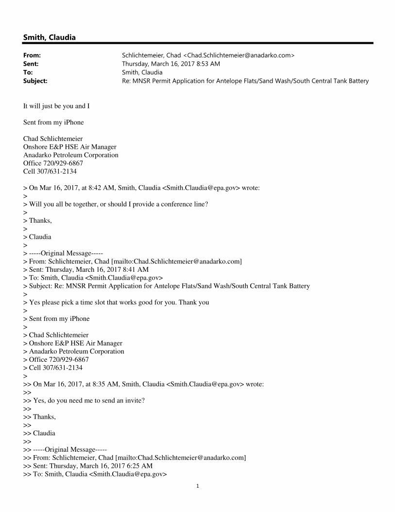
1
Smith, Claudia
From: Schlichtemeier, Chad <[email protected]>
Sent: Thursday, March 16, 2017 8:53 AM
To: Smith, Claudia
Subject: Re: MNSR Permit Application for Antelope Flats/Sand Wash/South Central Tank Battery
It will just be you and I
Sent from my iPhone
Chad Schlichtemeier
Onshore E&P HSE Air Manager
Anadarko Petroleum Corporation
Office 720/929-6867
Cell 307/631-2134
> On Mar 16, 2017, at 8:42 AM, Smith, Claudia <[email protected]> wrote:
>
> Will you all be together, or should I provide a conference line?
>
> Thanks,
>
> Claudia
>
> -----Original Message-----
> From: Schlichtemeier, Chad [mailto:[email protected]]
> Sent: Thursday, March 16, 2017 8:41 AM
> To: Smith, Claudia <[email protected]>
> Subject: Re: MNSR Permit Application for Antelope Flats/Sand Wash/South Central Tank Battery
>
> Yes please pick a time slot that works good for you. Thank you
>
> Sent from my iPhone
>
> Chad Schlichtemeier
> Onshore E&P HSE Air Manager
> Anadarko Petroleum Corporation
> Office 720/929-6867
> Cell 307/631-2134
>
>> On Mar 16, 2017, at 8:35 AM, Smith, Claudia <[email protected]> wrote:
>>
>> Yes, do you need me to send an invite?
>>
>> Thanks,
>>
>> Claudia
>>
>> -----Original Message-----
>> From: Schlichtemeier, Chad [mailto:[email protected]]
>> Sent: Thursday, March 16, 2017 6:25 AM
>> To: Smith, Claudia <[email protected]>
2
>> Subject: Re: MNSR Permit Application for Antelope Flats/Sand Wash/South Central Tank Battery
>>
>> Morning Claudia
>>
>> Does a call between 1-3 tomorrow work for you? Half hour should be plenty. Thanks Chad
>>
>> Sent from my iPhone
>>
>> Chad Schlichtemeier
>> Onshore E&P HSE Air Manager
>> Anadarko Petroleum Corporation
>> Office 720/929-6867
>> Cell 307/631-2134
>>
>>> On Mar 15, 2017, at 4:32 PM, Smith, Claudia <[email protected]> wrote:
>>>
>>> I'm pretty booked up tomorrow (Thursday 3/16). Are there any times on Friday (3/17) that would work? I have a call
from 9:30 to 10:30 MT, but otherwise am open.
>>>
>>> Thanks,
>>>
>>> Claudia
>>>
>>> -----Original Message-----
>>> From: Schlichtemeier, Chad [mailto:[email protected]]
>>> Sent: Wednesday, March 15, 2017 4:27 PM
>>> To: Smith, Claudia <[email protected]>
>>> Cc: Edrich, John [Tetra Tech Inc.] <[email protected]>
>>> Subject: Re: MNSR Permit Application for Antelope Flats/Sand Wash/South Central Tank Battery
>>>
>>> Thanks Claudia, I'm out this week but would be available for a call first thing tmw if that works on your end.
>>>
>>> Thanks
>>>
>>> Sent from my iPhone
>>>
>>> Chad Schlichtemeier
>>> Onshore E&P HSE Air Manager
>>> Anadarko Petroleum Corporation
>>> Office 720/929-6867
>>> Cell 307/631-2134
>>>
>>>> On Mar 15, 2017, at 3:53 PM, Smith, Claudia <[email protected]> wrote:
>>>>
>>>> Chad,
>>>>
>>>> I agree it is a good idea to have a discussion and submit a revised clean application. My response to John regarding
engine specific emission limits being in the CD were just off the top of my head, thinking about what went in to the
Cottonwood permit, but I did not have the CD in front of me at the time.
>>>>
>>>> Thanks,
>>>>
>>>> Claudia
>>>>
>>>> -----Original Message-----
>>>> From: Schlichtemeier, Chad [mailto:[email protected]]

3
>>>> Sent: Wednesday, March 15, 2017 11:51 AM
>>>> To: Edrich, John [Tetra Tech Inc.] <[email protected]>
>>>> Cc: Smith, Claudia <[email protected]>
>>>> Subject: Re: MNSR Permit Application for Antelope Flats/Sand Wash/South Central Tank Battery
>>>>
>>>> Hi Claudia
>>>>
>>>> I would like to step back and discuss whether a synthetic minor permit for any pollutant is required. Oxidation
catalyst are required on all engines meeting a 93% control efficiency by the CD. As shown in your email, this limits the
PTE of the facility well below the 250 tpy threshold. Therefore, incorporating the requirements of the CD into a permit
provides the enforceable requirements to limit the PTE. Sorry for the back and forth but as we discussed the purpose of
the application is to bring forward the CD requirements and not create new requirements. For Cottonwood, we had to
incorporate limits because the oxidation catalyst were required by ZZZZ, which EPA does not recognize as being
enforceable for CO. If it would be cleaner, we can resubmit the application.
>>>>
>>>> Let me know what you think.
>>>>
>>>> Thanks, Chad
>>>>
>>>> Chad Schlichtemeier
>>>> Onshore E&P HSE Air Manager
>>>> Anadarko Petroleum Corporation
>>>> (720)929-6867 - Office
>>>> (307)631-2134 - Cell
>>>>
>>>> Sent from my iPad
>>>>
>>>> On Mar 15, 2017, at 9:20 AM, Edrich, John [Tetra Tech Inc.]
<[email protected]<mailto:[email protected]>> wrote:
>>>>
>>>> Hi Claudia,
>>>>
>>>> Thanks for the information. The question was based on a read of Paragraph 77 of the Consent Decree, which states
>>>>
>>>> VI. Limits on Potential to Emit
>>>> 77. The PTE for CO and formaldehyde for all RICE in the Uinta Basin with a nameplate rating of 500 hp or greater
shall be limited by the requirement that emissions be controlled by catalysts which meet the destruction efficiency for CO
set forth in Paragraphs 41 and 50 and shall be federally enforceable on that basis.
>>>>
>>>> Paragraphs 41 and 50, of course, are the requirement to install oxidation catalyst achieving 93% destruction
efficiency. The CD contains no other emission limits on these engines, such as g/hp-hr or tpy, etc.
>>>>
>>>> Thanks,
>>>>
>>>> John Edrich
>>>> GNB Air Quality Support
>>>> Anadarko Petroleum Corporation
>>>> Direct: 720-929-3146
>>>> Mobile: 303-921-1010
>>>>
>>>> From: Smith, Claudia [mailto:[email protected]]
>>>> Sent: Tuesday, March 14, 2017 4:30 PM
>>>> To: Edrich, John [Tetra Tech Inc.] <[email protected]<mailto:[email protected]>>
>>>> Subject: RE: MNSR Permit Application for Antelope Flats/Sand Wash/South Central Tank Battery
>>>>
>>>> John,

4
>>>>
>>>> According to EPA guidance, when permits require add-on controls operated at a specified efficiency level, in order
to ensure that the efficiency condition is enforceable as a practical matter, permits should include those operating
parameters and assumptions which we depended upon to determine that the control equipment would have a given control
efficiency. Therefore, we would need to put directly into the permit the optimal catalyst inlet temperature ranges and
pressure drop across the catalyst ranges specified by the manufacturer of the catalyst. I did not see that information for the
engines in the application.
>>>>
>>>> Further, if the intent of the requested conditions is to appropriately limit potential to emit, defined as the product of
a source's emission rate at maximum operating capacity, capacity utilization, and hours of operation, an operational limit
(i.e. 93% CO reduction using oxidation catalyst) must be accompanied by an emission rate limitation over a certain time
period, preferably as short as possible, but no more than on a monthly basis. Typically for limiting PTE from engines, we
have used a g/hp-hr and/or lbs/hr limit associated with the operational limits.
>>>>
>>>> The CD contained both the 93% CO reduction, as well as the g/hp-hr emission limits. We could do lbs/hr limits if
you believe it would be more practically achievable. A 93% CO reduction for the 2,370 hp engines would result in 0.91
lbs/hr, for instance. We could alternatively do rolling 12-month engine-specific limits in tpy, which would come to 3.98
tpy for each 2,370 hp engine.
>>>>
>>>> Below are links to our most often consulted guidance on limiting PTE:
>>>>
>>>> https://www3.epa.gov/ttn/atw/pte/june13_89.pdf
>>>>
>>>> https://www.epa.gov/sites/production/files/2015-07/documents/potoem.pdf
>>>>
>>>> "In general, practical enforceability for a source-specific permit term means that the provision must specify (1) a
technically accurate limitation and the portions of the source subject to the limitation; (2) the time period for the limitation
(hourly, daily, monthly, annually); and (3) the method to determine compliance including appropriate monitoring, record
keeping and reporting."
>>>>
>>>> Thanks,
>>>>
>>>> Claudia
>>>>
>>>> From: Edrich, John [Tetra Tech Inc.] [mailto:[email protected]]
>>>> Sent: Tuesday, March 14, 2017 3:19 PM
>>>> To: Smith, Claudia <[email protected]<mailto:[email protected]>>
>>>> Subject: RE: MNSR Permit Application for Antelope Flats/Sand Wash/South Central Tank Battery
>>>>
>>>> Would we need to have an engine specific g/hp-hr emission limit? Or could the permit only specify 93% control
based on pre- and post- catalyst CO concentrations?
>>>>
>>>> -John
>>>>
>>>>
>>>> From: Smith, Claudia [mailto:[email protected]]
>>>> Sent: Tuesday, March 14, 2017 2:29 PM
>>>> To: Edrich, John [Tetra Tech Inc.] <[email protected]<mailto:[email protected]>>
>>>> Subject: RE: MNSR Permit Application for Antelope Flats/Sand Wash/South Central Tank Battery
>>>>
>>>> John,
>>>>
>>>> The engine detail sheets list a PTE g/hp-hr emission factors that are only 20% CO reduction. I assume you are
looking to have engine limits that reflect 93% CO reduction (for instance the uncontrolled CO g/hp-hr for the 2,370 hp
engines is listed as 2.50 g/hp-hr, so 93% reduction would result in an engine-specific limit of 0.17 g/hp-hr).
>>>>

5
>>>> Thanks,
>>>>
>>>> Claudia
>>>>
>>>> From: Edrich, John [Tetra Tech Inc.] [mailto:[email protected]]
>>>> Sent: Tuesday, March 14, 2017 2:23 PM
>>>> To: Smith, Claudia <[email protected]<mailto:[email protected]>>
>>>> Subject: RE: MNSR Permit Application for Antelope Flats/Sand Wash/South Central Tank Battery
>>>>
>>>> Claudia,
>>>>
>>>> Yes that is correct. Regardless of NSPS JJJJ requirements, we'll still need to meet the 93% CO reduction
requirement of the Consent Decree.
>>>>
>>>> Thank you,
>>>>
>>>> John Edrich
>>>> GNB Air Quality Support
>>>> Anadarko Petroleum Corporation
>>>> Direct: 720-929-3146
>>>> Mobile: 303-921-1010
>>>>
>>>>
>>>>
>>>> From: Smith, Claudia [mailto:[email protected]]
>>>> Sent: Tuesday, March 14, 2017 2:10 PM
>>>> To: Edrich, John [Tetra Tech Inc.] <[email protected]<mailto:[email protected]>>
>>>> Subject: RE: MNSR Permit Application for Antelope Flats/Sand Wash/South Central Tank Battery
>>>>
>>>> Thank you, John,
>>>>
>>>> For clarification, Anadarko still wants the permit to cover all seven engines, not just the four engines that are not
subject to NSPS JJJJ? If so, is that because the NSPS JJJJ requirements alone do not meet the 93% CO reduction
requirement?
>>>>
>>>> Thanks,
>>>>
>>>> Claudia
>>>>
>>>> From: Edrich, John [Tetra Tech Inc.] [mailto:[email protected]]
>>>> Sent: Tuesday, March 14, 2017 10:41 AM
>>>> To: Smith, Claudia <[email protected]<mailto:[email protected]>>
>>>> Subject: RE: MNSR Permit Application for Antelope Flats/Sand Wash/South Central Tank Battery
>>>>
>>>> Hello Claudia,
>>>>
>>>> I am forwarding this on behalf of Chad who is out on vacation this week.
>>>>
>>>> We agree that facility-wide emission limits are not needed.
>>>>
>>>> Regarding the Antelope Flats engines, in order to keep the Consent Decree (CD) requirements federally enforceable
in the MNSR permit, we only need permit conditions specifying engines 500 hp or greater must be lean burn or achieve
comparable emission reductions and be equipped with catalyst controls achieving at least 93% destruction efficiency for
CO (CD language).
>>>>

6
>>>> We want to continue using annual JJJJ testing on the JJJJ engines and portable analyzer testing on the balance of the
engines to demonstrate control efficiency and show the facility is under major source limits.
>>>>
>>>> Consistent with our comments on the draft permit for Cottonwood Wash, we are not seeking additional conditions
or redundant language in the MNSR permit from NSPS JJJJJ or NESHAP ZZZZ, as the respective engines are already
subject to the requirements of these Subparts.
>>>>
>>>> Hope this helps. Thanks for all of your effort helping us get these permits in place in order to terminate the CD.
>>>>
>>>>
>>>> John Edrich
>>>> GNB Air Quality Support
>>>> Anadarko Petroleum Corporation
>>>> Direct: 720-929-3146
>>>> Mobile: 303-921-1010
>>>>
>>>>
>>>>
>>>>
>>>> From: Smith, Claudia [mailto:[email protected]]
>>>> Sent: Wednesday, March 08, 2017 4:51 PM
>>>> To: Schlichtemeier, Chad <[email protected]<mailto:[email protected]>>;
Ohlhausen, Natalie <[email protected]<mailto:[email protected]>>
>>>> Subject: RE: MNSR Permit Application for Antelope Flats/Sand Wash/South Central Tank Battery
>>>>
>>>> Chad/Natalie,
>>>>
>>>> I also notice that 3 of the engines at ATF are subject to NSPS JJJJ with federally enforceable CO emission limits
that you are complying with using oxidation catalysts. Therefore, should the permit only contain conditions for the other
4 engines that are only subject to the area source requirements of NESHAP ZZZZ, which does not require oxidation
catalyst controls?
>>>>
>>>> Thanks,
>>>>
>>>> Claudia
>>>>
>>>> From: Smith, Claudia
>>>> Sent: Wednesday, March 08, 2017 4:10 PM
>>>> To: Schlichtemeier, Chad ([email protected]<mailto:[email protected]>)
<[email protected]<mailto:[email protected]>>; Ohlhausen, Natalie
([email protected]<mailto:[email protected]>)
<[email protected]<mailto:[email protected]>>
>>>> Subject: MNSR Permit Application for Antelope Flats/Sand Wash/South Central Tank Battery
>>>>
>>>> Chad/Natalie,
>>>>
>>>> While internal review is in process for the final MNSR permit for Cottonwood Wash, I have begun drafting the
proposed MNSR permit for Antelope Flats/Sand Wash/South Central Tank Battery. The application requests facility-wide
emission limits for NOX, CO, and VOC of 240 tpy each. Based on the emissions calculations provided, and considering
the requested limits for the Cottonwood Wash CS permit, it does not appear that facility-wide emission limits are
necessary for this permit and that unit-specific CO limits for the engines could serve to memorialize the CD requirements,
along with conditions for the low-emission dehydrators and pneumatic controllers (similar to the revised conditions
Anadarko suggested in the comments to the proposed permit for Cottonwood Wash).
>>>>
>>>> Can you please verify that you really want to request facility-wide VOC, NOX and CO emission limits?
>>>>

7
>>>> Thank you,
>>>>
>>>> Claudia Young Smith
>>>> Environmental Scientist
>>>> Air Program, Mail Code 8P-AR
>>>> US Environmental Protection Agency Region 8
>>>> 1595 Wynkoop Street
>>>> Denver, Colorado 80202
>>>>
>>>> Phone: (303) 312-6520
>>>> Fax: (303) 312-6064
>>>> http://www.epa.gov/caa-permitting/caa-permitting-epas-mountains-and-plains-region
>>>> *******************************************************************
>>>>
>>>>
>>>> Click here for Anadarko's Electronic Mail Disclaimer<http://www.anadarko.com/notices/Pages/Electronic-Mail-
Disclaimer.aspx>
>>>
>>>
>>>
>>>
>>> Click here for Anadarko's Electronic Mail Disclaimer<http://www.anadarko.com/notices/Pages/Electronic-Mail-
Disclaimer.aspx>
>
>
>
>
> Click here for Anadarko’s Electronic Mail Disclaimer<http://www.anadarko.com/notices/Pages/Electronic-Mail-
Disclaimer.aspx>