Small angle stability
30
SMALL ANGLE STABILITY: Transverse Stability
-
Upload
muhammad-adli-bin-jaaffar -
Category
Engineering
-
view
298 -
download
7
Transcript of Small angle stability

SMALL ANGLE STABILITY: Transverse Stability

M
Weight
B
G
B
Buoyancy Force
K

Forces Acting on a Floating Body
Force due to Gravity
• The force of gravity acts on weight of each little part of the ship. p p
• To simplify all of these acting weights, they are resolved into one resultant force, called the resultant weight or , gdisplacement (ΔS) of the ship.
• This gravitational force, or resultant weight, is resolved to act at the center g ,of gravity (G), which is simply the weighted average location of all of the weights that make up a ship. See
i i i i i iFigure 4.0. Figure 4.0: Ship at Static Equilibrium Showing Resultant Weight & Distributed
and Buoyancy Forces

Force due to Buoyancy
Th d t f di t ib t d• The second system of distributed forces on a freely floating ship comes from the pressure exerted on the submerged part of the hull by thesubmerged part of the hull by the water. These hydrostatic forces act perpendicular to the surface of the hull and can be resolved into u a d ca be eso ed ohorizontal and vertical components with respect to the surface of the water.
• The sum of the horizontal hydrostatic forces will be zero. This should make sense to you. If the horizontal forces Figure 4.0: Ship at Static Equilibrium
didn’t balance it would imply that a ship would move through the water all by itself without power or external f h k d f
Showing Resultant Weight & Distributed and Buoyancy Forces
forces. This kind of spontaneous movement does not occur.

Force due to Buoyancy
Th f th ti l h d t ti• The sum of the vertical hydrostatic forces is not zero. The net vertical force is called the resultant buoyant force (F ) This force like weight isforce (FB ). This force, like weight, is resolved to act at a unique point. The buoyant force acts at the center of buoyancy (B), which is the geometric buoya cy ( ), c s e geo e ccentroid of the underwater volume. See Figure 4.0.
• The resultant weight and the resultant gbuoyant force always act perpendicular to the surface of the water. Resultant buoyant force acts
Figure 4.0: Ship at Static Equilibrium Showing Resultant Weight & Distributed
and Buoyancy Forces
upward while the resultant weight force acts downward.
and Buoyancy Forces

New States of Static Equilibrium Due to Weight Additions Removals and Shifts on a FloatingAdditions, Removals and Shifts on a Floating
Ship. • Now we want to look at the new static equilibrium condition after• Now we want to look at the new static equilibrium condition after
changing the weight distribution on a ship.
• An altered weight distribution will cause the Center of Gravity (G) to
move.
• To fully identify the location of G before and after its movement, we must
be able to visualize and sketch the distribution of G points for each weight p g
(approximately) .
• As with the other centroids, the location of G is referenced vertically to
the keel (KG) or the Vertical Center of Gravity (VCG) transversely to thethe keel (KG) or the Vertical Center of Gravity (VCG), transversely to the
centerline with the Transverse Center of Gravity (TCG) and longitudinally
to either of the perpendiculars or midships with the Longitudinal Center of
Gravity (LCG). Recall that the correct sign convention is negative to port of
the centerline and aft of midships.

• The weight distribution on a ship can change whenever:
A weight is shifted in any one of three separate directions
A weight is added or removed from anywhere on a ship
By some combination of the above. y
• At first, it is manageable if we break it down into a study of three separate
directions and then further break it down into shifts additions anddirections and then further break it down into shifts, additions, and
removals in each of these directions.
• This process will be stepped through over the following pages.
• On a ship the distribution of weight is constantly changing and it would be
desirable to know the final static equilibrium position of your ship after
these changes. g
• If these final conditions are undesirable the captain can take actions to
avoid or minimize the effects.

Qualitative Analysis of Weight Additions, R l d ShifRemovals and Shifts
Weight AdditionWeight Addition
• When weight is added to a ship the average location of the weight of the ship mustlocation of the weight of the ship must move towards the location of the weight addition.
• Consequently the Center of Gravity of the• Consequently, the Center of Gravity of the ship (G) will move in a straight line from its current position toward the center of gravity of the weight (g) being added.gravity of the weight (g) being added.
• An example of this is shown in Figure 4.1.Figure 4.1: The Effects of a
Weight Addition on the Centre of Gravity of a Shipy p

Qualitative Analysis of Weight Additions, R l d ShifRemovals and Shifts
Weight Removal
• When weight is removed from a ship the average location of the weight ofthe average location of the weight of the ship must move away from the location of the removal.
• Consequently the Center of Gravity of• Consequently, the Center of Gravity of the ship (G) will move in a straight line from its current position away from the center of gravity of the weight (g) beingcenter of gravity of the weight (g) being removed. See Figure 4.2. Figure 4.2: The Effects of a
Weight Removal on the Centre of Gravity of a Ship
Qualitative Analysis of Weight Additions, R l d ShifRemovals and Shifts
Weight Shift g
• When a small weight is shifted onboard a ship the Center of Gravity of the ship (G) will move in a direction parallel to the shift but through a much smaller distance.
• G will not move as far as the weight being shifted because the weight is only a small fraction of the total weight fof the ship.
• An example of this is shown in Figure 4.3.
Figure 4.3: The Effects of a Weight Shift on the Centre
of Gravity of a Ship

Qualitative Analysis of Weight Additions, R l d ShifRemovals and Shifts
Weight Combination Effect
• An explanation of this can be provided by the way a weight shift can be modeled.
• A weight shift can be considered as a removal of a weight from its previous position and the addition of a weight at its new position. p
• Figure 4.4 demonstrates this principle using the rules governing weight additions and removals discussed previously.previously.
• Having established some qualitative rules, we are now in a position to quantify the magnitude of any movement in G
Figure 4.4: A Weight Shift Being Modeled as a Weight
Removal Followed by a Weight Addition
movement in G.

Combining Vertical and Transverse Weight Shifts Weight Additions or Weight RemovalsShifts, Weight Additions or Weight Removals
• Qualitatively, we know that G will move directly towards the location of the added weightweight.
• In this example (Figure 4.5), it results in an increase in KG and a TCG starboard of the centerline. Theoretically, it should be possible to calculate the new location of Gpossible to calculate the new location of G in one step. However, significant simplification is achieved by breaking the problem down into the vertical and transverse directionstransverse directions.
• The steps for carrying out an analysis of this situation would be:
Q lit ti l d t i th i t l tiQualitatively determine the approximate location of Gnew. Perform a vertical analysis to calculate KGnew(due to vertical weight changes)Perform a transverse analysis to calculate the
Figure 4.5: Combining Vertical and Transverse Weight Changes
Perform a transverse analysis to calculate the overall angle of list (due to transverse weight changes)

Vertical Changes in the Ship’s Center of Gravity D W i h Shif W i h Addi i dDue to Weight Shifts, Weight Additions, and
Weight Removals.
• As stated previously, the Center of Gravity of a ship (G) is the point at which the all the mass of the ship can be considered to be locatedwhich the all the mass of the ship can be considered to be located.
• It is the point at which the gravitational forces acting on the ship may be resolved to act. G is referenced vertically from the keel of the ship (K).
• The distance from K to G is labeled KG with a bar over the letters to• The distance from K to G is labeled KG with a bar over the letters to indicate it is a line segment representing a distance.
• It is important to keep track of the vertical location of G to predict equilibrium conditions in particular it has a considerable bearing on theequilibrium conditions, in particular it has a considerable bearing on the initial and overall stability of a ship.

Weight Addition
• Let us consider the situation where a weight is added vertically above G on the centerline of the shipthe centerline of the ship.
• We already know from a qualitative analysis that G will move directly towards the location of the weight gaddition, so in this instance, it will move vertically from Gold to G new.
• What remains is to quantify the d f hmagnitude of this movement.
• The KG new of the ship can be calculated by doing a weighted average of the distances from the keel to G and gdistances from the keel to Gold and g with a weighting factor based on a weight ratio. This relationship is shown in the equation below and it is
Figure 4.6: A Weight Addition Vertically b Gspecifically for the addition of one
weight in the vertical direction.
above G

or
Weight KG (m) Moment
∆S old KG old ∆S old x KG old
wa Kg a wa x Kg a
∆S new = ΣmomentA Weight Addition Σ weight
KG new = (Σmoment) / (∆S new )
gVertically above G
new S new
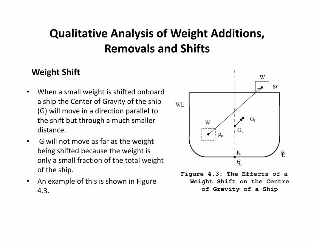
Weight Removal
• In a similar manner to the weight addition example, let us consider what will happen if a weight is removed from a position g pabove G and on the centerline.
• Qualitatively, we know G will move directly away from the weight removal, moving from Gold to Gnew. Hence we would expect that KGnewwould be less than KG old.
• Once again, the magnitude of KGnew can be d i d i i h i h ddetermined using either weighted averages or by taking moments a the keel.
• However, since in this case the weight is being removed the correct sign for the
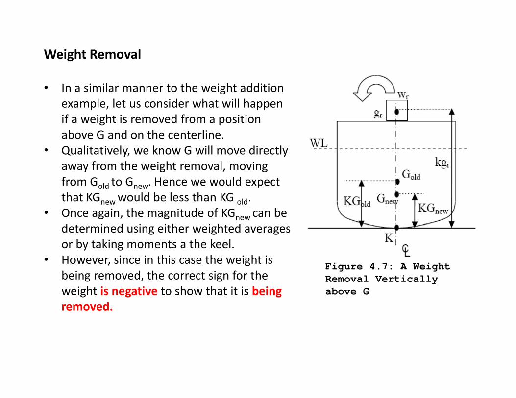
Figure 4.7: A Weight being removed, the correct sign for the weight is negative to show that it is being removed.
Removal Vertically above G
or
Weight KG (m) Moment
∆S old KG old ∆S old x KG oldA W i ht R l
‐wr Kg r ‐wr x Kg r
A Weight Removal Vertically above G
ve sign indicates that the
∆S new = Σ weight
Σmoment
‐ve sign indicates that the weight is removed KG new = (Σmoment) / (∆S new )

Weight Shift L t di i l ti l i ht• Let us now discuss a single vertical weight shift.
• We have already seen that one can model a i l hif h l f i hvertical shift as the removal of a weight
from one position and the addition of the same weight at a new position.
• If we view it this way we can combine the equations for a vertical weight removal and addition to quantify this scenario.
• The formulation next shows this combination.
• Notice that the negative sign attached to Figure 4.8: A Single Vertical Weight Shift
wr to make the removal term negative. Vertical Weight Shift

• Since the weight removed is the same weight added and therefore is gequal in magnitude, the above equation can be re‐written as:
or
Weight KG (m) Moment
∆S old KG old ∆S old x KG old
‐wr Kg r ‐wr x Kg r
wa Kg a wa x Kga∆S new = Σ weight
ΣmomentA Single Vertical Weight Shift
‐ve sign indicates that the weight is removed
KG new = (Σmoment) / (∆S new )

Transverse Changes in the Ship’s Center of G i D W i h Shif W i h Addi iGravity Due to Weight Shifts, Weight Additions,
and Weight Removals.
• Recall the transverse direction is the “side to side” direction (or the port to starboard direction).
• The centerline of the ship separates the port from the starboard. Recall that distances to the port are defined to be negative, and distances to the starboard are positive.
• In general, we use the symbol “y” as the general variable to represent a transverse distance from the centerline of the ship.
• Qualitatively, we know that should a weight be added or removed off center (not on the centerline) or a weight is shifted transversely across the ship, the ship will assume some angle of inclination.
• This angle is called an angle of “List”.

• A List is the condition where the ship is in pstatic equilibrium and down by the port or starboard side.
• In other words, the ship is not level in the , pwater from side to side.
• The list angle is created because the weight change has resulted in the Center of Gravity g y(G) of the ship to move from the centerline.
• There are no external forces acting on the ship to keep it down by the port or p p y pstarboard.
• The angle is maintained because the resultant weight and buoyant force are g yvertically aligned
• The off center G causes a moment to be created within the ship that causes it to protate.

• As the ship rotates, the underwater volume changes shape which causes the Center of Buoyancy (B) of the ship to move.
• At small angles of list, B moves in an arc, centered at the transverse metacenter (M). I i il h h f h d l B• It continues to move until the shape of the underwater volume causes B to move directly vertically underneath G, causing the ship to be back in static equilibrium.
• The amount of list is usually measured in degrees of incline from the level• The amount of list is usually measured in degrees of incline from the level condition.
• In general, symbol “φ” (phi) is used as the general variable to represent an angle of inclination to the port (negative sign) or starboard side (positive g p ( g g ) (psign).
• The center of gravity (G) is referenced in the transverse direction from the centerline of the ship.
• The distance from the centerline of the ship to the center of gravity of the ship is called the transverse center of gravity (TCG) and is measured in units of meter.

• All items should be labeled with the proper symbols including the angle of inclination (φ), the waterline (WL), the (φ), ( ),transverse metacenter (M), the ship’s center of gravity initially (G0), the ship’s final center of gravity (G1), the center of buoyancy (B), the resultant weight of the ship (Δ S), the resultant buoyant force (FB), centerline (CL), and keel (K).
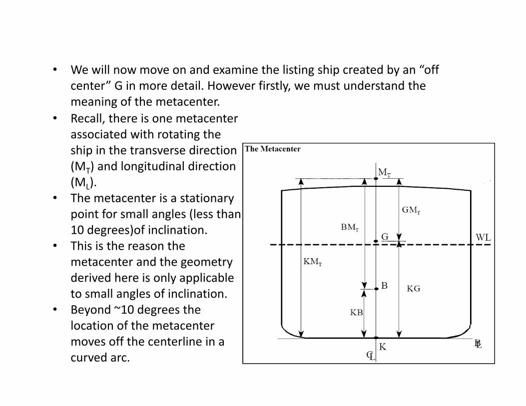
• We will now move on and examine the listing ship created by an “off g p ycenter” G in more detail. However firstly, we must understand the meaning of the metacenter.
• Recall, there is one metacenterassociated with rotating the ship in the transverse direction (MT) and longitudinal direction ( )(ML).
• The metacenter is a stationary point for small angles (less than 10 degrees)of inclination10 degrees)of inclination.
• This is the reason the metacenter and the geometry derived here is only applicablederived here is only applicable to small angles of inclination.
• Beyond ~10 degrees the location of the metacentermoves off the centerline in a curved arc.

Calculating the Angle of List for Small Angles After a Transverse Shift of Weightof Weight
• Consider a ship floating upright. The centers of gravity and buoyancy are on the centerline. The resultant force
M
acting on the ship is zero, and the resultant moment about the center of gravity is zero. B
G
the center of gravity is zero.
K

• Now let a weight already M
wa
onboard the ship be shifted transversely such that G moves to G1.
BG G1
1
• This will produce a listing t d th hi ill t t
K
moment and the ship will start to list until G1 and the centre of buoyancy are in the same
ti l liG
vertical line. B
K
B1
K

• In this position G1 will also lie vertically under M so long as the angle of list is small. Therefore, if the final positions ofsmall. Therefore, if the final positions of all points are known, the final list can be found, using trigonometry in the triangle GG1M which is right angle at G B
G
Btriangle GG1M which is right angle at G
• In triangle GG1M: KdwGG ×
=)(
B1Weight of shifted/added/removed
Φ
M
GMGGTan
GG
o =
Δ=
φ 1
1
TCG of the shifted/added/removed
Φ
Gtli tiGM
dwTan
GMo
×Δ×
=φListing Moment weight
G
G1GMmomentlistingTan o
×Δ=φ

Exercise 1
A vessel of 13000 tonnes, with KM 10.5m (assumed constant) and KG 9.5m loads;
400 tonnes at KG 2.9m
900 tonnes at KG 6.0m
1500 tonnes at KG 10.6m
2000 tonnes at KG 8 3m2000 tonnes at KG 8.3m
She also discharges:
700 tonnes at KG 1.5m and
300 tonnes at KG 12.7mCalculate the final weight, KG and GM
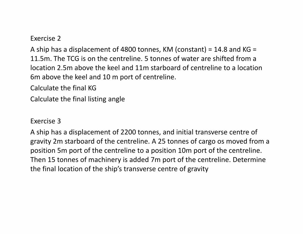
Exercise 2
A ship has a displacement of 4800 tonnes, KM (constant) = 14.8 and KG = 11.5m. The TCG is on the centreline. 5 tonnes of water are shifted from a location 2.5m above the keel and 11m starboard of centreline to a location 6m above the keel and 10 m port of centreline.
Calculate the final KG
Calculate the final listing angleg g
Exercise 3
A ship has a displacement of 2200 tonnes and initial transverse centre ofA ship has a displacement of 2200 tonnes, and initial transverse centre of gravity 2m starboard of the centreline. A 25 tonnes of cargo os moved from a position 5m port of the centreline to a position 10m port of the centreline. Then 15 tonnes of machinery is added 7m port of the centreline. DetermineThen 15 tonnes of machinery is added 7m port of the centreline. Determine the final location of the ship’s transverse centre of gravity

Exercise 4
A ship of 8000 tonnes displacement has KM = 8.7m, and KG =7.6m. The following weights are then loaded and discharged:
Load 250 tonnes cargo at KG 6.1m and centre of gravity 7.6m to starboard of the centerline
Load 300 tonnes fuel oil at KG 0.6m and centre of gravity 6.1m to port of the centerline
Discharge 50 tonnes of ballast at KG 1.2m and centre of gravity 4.6m to port of the centerline
Determine the final list